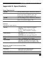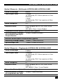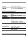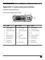
1
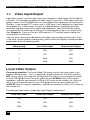
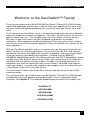
THE SERVSWITCH FAMILY Welcome to the ServSwitch™ Family! Thank you for purchasing a BLACK BOX® ServSwitch™ Brand DVI KVM Extender model! We appreciate your business, and we think you’ll appreciate the many ways that your enhanced keyboard/video/mouse system will save you money, time, and effort. That’s because our ServSwitch family is all about breaking away from the traditional, expensive model of computer management. You know, the one-size-fits-all-even-if-itdoesn’t model that says, “One computer gets one user station, no more, no less.” Why not a single user station (monitor, keyboard, and mouse) for multiple computers—even computers of different platforms? Why not a pair of user stations, each of which can control multiple computers? Why not multiple user stations for the same computer? With our ServSwitch products, there’s no reason why not. We carry a broad line of robust solutions for all these applications. Do you have just two PCs, and need an economical alternative to keeping two monitors, keyboards, and mice on your desk? Or do you need to share dozens of computers, including a mix of IBM® PC, RS/6000®, Apple® Macintosh®, Sun Microsystems®, and SGI™ compatibles among multiple users with different access levels? Does your switch have to sit solidly on a worktable and use regular everyday cables? Or does it have to be mounted in an equipment rack and use convenient many-to-one cables? No matter how large or small your setup is, no matter how simple or how complex, we’re confident we have a ServSwitch system that’s just right for you. The ServSwitch™ family from Black Box—the one-stop answer for all your KVMswitching needs! This manual will tell you all about your new ServSwitch™ Brand DVI KVM Extender, including how to install, operate, and troubleshoot it. For an introduction to the Extender, see Chapter 2. The Extender product codes covered in this manual are: ACS253A-CT ACS253A-MM ACS253A-SM ACS253A-U-MM ACS253A-U-SM 1 SERVSWITCH BRAND DVI KVM EXTENDER FAMILY Copyrights and Trademarks ©2004. All rights reserved. This information may not be reproduced in any manner without the prior written consent of the manufacturer. Information in this document is subject to change without notice and the manufacturer shall not be liable for any direct, indirect, special, incidental or consequential damages in connection with the use of this material. All trademark and trade names mentioned in this document are acknowledged to be the property of their respective owners. Disclaimer While every precaution has been taken in the preparation of this manual, the manufacturer assumes no responsibility for errors or omissions. Neither does the manufacturer assume any liability for damages resulting from the use of the information contained herein. The manufacturer reserves the right to change the specifications, functions, or circuitry of the product without notice. The manufacturer cannot accept liability for damage due to misuse of the product or due to any other circumstances outside the manufacturer’s control (whether environmental or installation related). The manufacturer shall not be responsible for any loss, damage, or injury arising directly, indirectly, or consequently from the use of this product. Cautions and Notes The following symbols are used in this guide: CAUTION. This indicates an important operating instruction that should be followed to avoid any potential damage to hardware or property, loss of data, or personal injury. NOTE. This indicates important information to help you make the best use of this product. 2 FCC/CDC STATEMENTS FEDERAL COMMUNICATIONS COMMISSION AND CANADIAN DEPARTMENT OF COMMUNICATIONS RADIO-FREQUENCY INTERFERENCE STATEMENTS This equipment generates, uses, and can radiate radio-frequency energy, and if not installed and used properly, that is, in strict accordance with the manufacturer’s instructions, may cause interference to radio communication. It has been tested and found to comply with the limits for a Class A computing device in accordance with the specifications in Subpart B of Part 15 of FCC rules, which are designed to provide reasonable protection against such interference when the equipment is operated in a commercial environment. Operation of this equipment in a residential area is likely to cause interference, in which case the user at his own expense will be required to take whatever measures may be necessary to correct the interference. Changes or modifications not expressly approved by the party responsible for compliance could void the user’s authority to operate the equipment. Shielded PC-equipment cables must be used with this equipment to maintain compliance with radio frequency energy emission regulations and ensure a suitably high level of immunity to electromagnetic disturbances. This digital apparatus does not exceed the Class A limits for radio noise emission from digital apparatus set out in the Radio Interference Regulation of the Canadian Department of Communications. Le présent appareil numérique n’émet pas de bruits radioélectriques dépassant les limites applicables aux appareils numériques de la classe A prescrites dans le Règlement sur le brouillage radioélectrique publié par le Ministerié des Communications du Canada. 3 SERVSWITCH BRAND DVI KVM EXTENDER FAMILY EUROPEAN UNION DECLARATION OF CONFORMITY This is to certify that, when installed and used according to the instructions in this manual, together with the specified cables and the maximum cable length <3m, the Units: ACS253A-CT (ACS253A-DVI-CT) ACS253A-MM (ACS253A-DVI-MM) ACS253A-SM (ACS253A-DVI-SM) ACS253A-U-MM ACS253A-U-SM are shielded against the generation of radio interferences in accordance with the application of Council Directive 89/336/EEC as well as these standards: EN 55022: EN 55024: IEC 61000-4-2: IEC 61000-4-3: IEC 61000-4-4: EN 61000-3-2 EN 61000-3-3 1999 1999 2001 2001 2001 2001 2002 Class A The device was tested in a typical configuration with PC. This equipment has been found to comply with the limits for a Class A digital device, pursuant to Part 15 of the FCC Rules. These limits are designed to provide reasonable protection against harmful interference when the equipment is operated in a commercial environment. This equipment generates, uses, and can radiate radio frequency energy and, if not installed and used in accordance with the instruction manual, may cause harmful interference to radio communications. Operation of this equipment in a residential area is likely to cause harmful interference in which case the user will be required to correct the interference at his own expense. 4 NOM STATEMENT NORMAS OFICIALES MEXICANAS (NOM) ELECTRICAL SAFETY STATEMENT INSTRUCCIONES DE SEGURIDAD 1. Todas las instrucciones de seguridad y operación deberán ser leídas antes de que el aparato eléctrico sea operado. 2. Las instrucciones de seguridad y operación deberán ser guardadas para referencia futura. 3. Todas las advertencias en el aparato eléctrico y en sus instrucciones de operación deben ser respetadas. 4. Todas las instrucciones de operación y uso deben ser seguidas. 5. El aparato eléctrico no deberá ser usado cerca del agua—por ejemplo, cerca de la tina de baño, lavabo, sótano mojado o cerca de una alberca, etc.. 6. El aparato eléctrico debe ser usado únicamente con carritos o pedestals que sean recomendados por el fabricante. 7. El aparato eléctrico debe ser montado a la pared o al techo sólo como sea recomendado por el fabricante. 8. Servicio—El usuario no debe intentar dar servicio al equipo eléctrico más allá a lo descrito en las instrucciones de operación. Todo otro servicio deberá ser referido a personal de servicio calificado. 9. El aparato eléctrico debe ser situado de tal manera que su posición no interfiera su uso. La colocación del aparato eléctrico sobre una cama, sofá, alfombra o superficie similar puede bloquea la ventilación, no se debe colocar en libreros o gabinetes que impidan el flujo de aire por los orificios de ventilación. 10. El equipo eléctrico deber ser situado fuera del alcance de fuentes de calor como radiadores, registros de calor, estufas u otros aparatos (incluyendo amplificadores) que producen calor. 11. El aparato eléctrico deberá ser connectado a una fuente de poder sólo del tipo descrito en el instructivo de operación, o como se indique en el aparato. 12. Precaución debe ser tomada de tal manera que la tierra fisica y la polarización del equipo no sea eliminada. 13. Los cables de la fuente de poder deben ser guiados de tal manera que no sean pisados ni pellizcados por objetos colocados sobre o contra ellos, poniendo particular atención a los contactos y receptáculos donde salen del aparato. 5 SERVSWITCH BRAND DVI KVM EXTENDER FAMILY 14. El equipo eléctrico debe ser limpiado únicamente de acuerdo a las recomendaciones del fabricante. 15. En caso de existir, una antena externa deberá ser localizada lejos de las lineas de energia. 16. El cable de corriente deberá ser desconectado del cuando el equipo no sea usado por un largo periodo de tiempo. 17. Cuidado debe ser tomado de tal manera que objectos liquidos no sean derramados sobre la cubierta u orificios de ventilación. 18. Servicio por personal calificado deberá ser provisto cuando: A: El cable de poder o el contacto ha sido dañado; u B: Objectos han caído o líquido ha sido derramado dentro del aparato; o C: El aparato ha sido expuesto a la lluvia; o D: El aparato parece no operar normalmente o muestra un cambio en su desempeño; o E: El aparato ha sido tirado o su cubierta ha sido dañada. 6 SAFETY PRECAUTIONS AND INSTALLATION GUIDELINES Safety Precautions and Installation Guidelines To ensure reliable and safe long-term operation, please note the following installation guidelines: • Do not use CATx-devices to link between buildings – please use fiber devices. • Only use in dry, indoor environments. • If the building has 3-phase AC power, try to ensure that equipment connected to the Local and Remote units is on the same phase. • Try not to route a CATx link cable alongside power cables. • Ensure that the system connected to the Local unit is connected to power ground. • Ensure that the monitor connected to the Remote unit is connected to power ground and does not use an isolated power supply. • The Remote unit, Local unit and any power supplies can get warm. Do not locate them in an enclosed space without any airflow. • Do not place a power supply directly on top of a unit. • Do not obstruct a unit’s ventilation holes. To safeguard against personal injury and avoid possible damage to equipment or property, please observe the following: • Only use power supplies originally supplied with the product or manufacturer-approved replacements. Do not attempt to dismantle or repair any power supply. Do not use a power supply if it appears to be defective or has a damaged case. • Connect all power supplies to grounded outlets. In each case, ensure that the ground connection is maintained from the outlet socket through to the power supply’s AC power input. • Do not attempt to modify or repair this product, or make a connection from the CATx link interface (RJ45) or the Fiber link interface (SC-Duplex) to any other products, especially telecommunications or network equipment. 7 SERVSWITCH BRAND DVI KVM EXTENDER FAMILY Optical Models Models: ACS253A-SM, ACS253A-MM, ACS253A-U-MM and ACS253A-U-SM DVI/VGA Upgrade Kits: ACS253A-DVI-MM and ACS253A-DVI-SM These are Class 1 Laser products. Multimode transceivers comply with IEC 825-1 and FD 21 CFR 1040.10 and 1040.11. Singlemode transceivers comply with IEC 60825-1 and FDA 21 CFR 1040.10 and 1040.11. To meet laser safety requirements, the transceivers shall be operated within the absolute maximum ratings. The use of optical instruments with this product may cause an eye hazard. All adjustments have been made at the factory prior to shipment of the device. No maintenance or alteration to the device is required. Tampering with or modifying the performance of the device will result in voided product warranty. Usage Restrictions Optical ports must be terminated with an optical connector or with a dust plug. Failure to adhere to the above restrictions could result in a modification that is considered an act of “manufacturing” and will require, under law, recertification of the modified product with the U.S. Food and Drug Administration (ref. 21 CFR 1040.10(i)). 8 CONTENTS Contents 1. Quick Setup 1.1 1.2 Video Input/Output Command Summary 2. Overview 2.1 2.2 2.3 2.4 2.5 2.6 Introduction Glossary Features Product Range Compatibility How to Use This Guide 3. Installation 3.1 3.2 3.3 3.4 3.5 3.6 Package Contents Interconnection Cable Requirements System Setup Diagnostic LEDs Access Switching Private Mode 4. Device Control 4.1 4.2 Opening the OSD Using the OSD 11 12 12 15 15 15 18 19 20 21 22 22 23 24 28 30 30 31 32 34 5. Monitor Setup 43 6. Extender Setup 44 6.1 6.2 Overview Setup Instructions for VGA Input 7. Troubleshooting 7.1 7.2 Video Keyboard & Mouse 44 45 47 47 48 9 SERVSWITCH BRAND DVI KVM EXTENDER FAMILY Appendix A: Example Applications 49 Appendix B: Rack Mount Options 54 Appendix C: System Upgrade & Dual Access 56 Appendix D: Video Modes and Frame Rates 57 Appendix E: USB – High Power/Low Power 59 Appendix F: Audio/Serial Upgrade 60 Appendix G: Calling Black Box 62 Appendix H: Specifications 63 Appendix I: 69 10 Connectors and Cables QUICK SETUP 1. Quick Setup This section briefly describes how to install your KVM extender system and optimize the video signals. Unless you are an experienced user, we recommend that you follow the full procedures described in the rest of this manual. Refer to the command summary on page 12 when following this procedure. Install system 1. 2. 3. 4. Connect Remote unit to KVM. Connect Local unit to CPU or switch. Connect Local and Remote units with matching interconnection cable (CATx, Multimode or Singlemode fiber). Power up the system. No Do you have a DVI monitor? Yes No Do you have a flat screen (TFT)? Yes Carry out the Monitor Setup procedure (please refer to its manual and see page 40 in this manual). Do you have a DVI source? Yes No Carry out VGA Input Setup procedure (please follow the instructions on page 42). Done 11 SERVSWITCH BRAND DVI KVM EXTENDER FAMILY 1.1 Video Input/Output If possible, always use DVI output from your computer’s video card and DVI input to a monitor. This provides the optimum video signal. If you use a VGA output from your graphic source, the ACS253A Local unit must digitize the signal prior to transmission. Similarly, if your remote TFT screen uses a VGA input, it must digitize the signal from the Remote unit. In both cases, the built-in video processors must determine the resolution and pixel phase for an optimized digitization. Your DVI Extender allows you to optimize the video signal manually or automatically using its on-screen utility (see Chapter 4). If you are using a VGA input to a TFT monitor, please follow the manufacturer’s instructions. You may have several possible options for video source output/monitor input. If this is the case, for the optimum video quality, please select the highest ranked available combination from the following table: Video Quality Local Unit Iinput Remote Unit Output 1 DVI DVI 2 DVI VGA 3 VGA DVI 4 VGA VGA Local Video Output Please pay attention! The Local Video Out always carries the same signal, your graphic card generates - this is in opposition to the remote out! The local unit does NOT do any signal translation for the local out! This means: If you connect the local unit to a VGA graphic card, the local Video Out will ALWAYS carry VGA signals regardless, whether you connect a VGA or DVI screen to the remote unit. And vice versa if you connect the local unit to a DVI graphic card, the local Video Out will ALWAYS carry DVI signals regardless, whether you connect a VGA or DVI screen to the remote unit. The following table shows all possible Input/Output combinations 12 Local Unit Iinput Local Unit Output Remote Unit Output DVI DVI DVI DVI DVI VGA VGA VGA DVI QUICK SETUP VGA VGA VGA 13 SERVSWITCH BRAND DVI KVM EXTENDER FAMILY 1.2 Command Summary The following table summarizes the ‘hot’ key command sequences used in system configuration and video tuning on a Remote unit console. Command Keyboard at Remote unit Terminal or Windows Utility program* Enter OSD <Left Control> + <Left Shift> + <I> <O> + <S> + <D> + <Enter> Exit OSD <ESC> <X> Select next position <Right Arrow> <R> Select previous position <Left Arrow> <L> Select Submenu <Enter> <S> Select parameter modification <Enter> <S> Increase parameter <Right Arrow> <R> Decrease parameter <Left Arrow> <L> Accept and store modified parameter <Enter> <S> Back to the Menu selection * Commands are not case-sensitive. 14 OVERVIEW 2. Overview 2.1 Introduction A basic KVM extension system comprises a Local unit (transmitter) and a Remote unit (receiver). The Local unit connects directly to the computer (or a KVM switch system) using the supplied cable(s). The user console (keyboard, mouse and monitor) attaches to the Remote unit. The Remote and Local units communicate video and data information along the interconnecting cable (see Figure 1). Local units offer dual access, allowing the connection of a second user console close to the computer. With the optional upgrade kit, you can also use ACS253A units to communicate stereo audio and serial port signals. The ServSwitch Brand DVI KVM Extender Series enables high-resolution video, PS/2 keyboard and mouse signals to be communicated up to: • 300ft (100m) over Category 5, 5e, 6 or higher (CATx) cable. • 1200ft (400m) over Multimode fiber cable (50/125µ). • 600ft (200m) over Multimode fiber cable (62.5/125µ). • 6¼ miles (10km) over Singlemode fiber cable (9/125µ). In a digital application (DVI input and output), there is no loss of picture quality irrespective of extension distance and no adjustments are required. The DVI KVM Extender Series also supports traditional analog VGA as well as digital DVI. All combinations of DVI and VGA (graphics cards and monitors) are supported, allowing equipment to be mixed. In a mixed analog/digital application, some adjustment of the video signal is necessary to optimize the analog-digital signal conversions. DVI KVM Extenders are equipped with various automatic and manual video correction tools in an on screen utility (see page 31). 2.2 Glossary The following terms are used in this guide: CATx Any Category 5, 5e, 6 or higher cable. Multimode Any multimode 2-fiber cable 50/125µ or 62.5/125µ Singlemode Any singlemode 2-fiber cable 9/125µ PSU The desktop power supply connected to the Local/Remote unit. KVM Keyboard, Video and Mouse. Console A keyboard, monitor, and mouse, plus optional serial/audio devices. Dual Access A system allowing connection of Local and Remote user consoles. 15 SERVSWITCH BRAND DVI KVM EXTENDER FAMILY Single Head An extender system that supports one monitor. Dual Head An extender system that supports two monitors. 16 OVERVIEW Local Access LOCAL unit KVM extension over CATx or fiber optic cables. REMOTE unit Dual Video Support Serial/Audio and USB extension options Figure 1 KVM extender system 17 SERVSWITCH BRAND DVI KVM EXTENDER FAMILY 2.3 Features All members of the ServSwitch Brand DVI KVM Extender Series offer the following features: • Support for high video resolution over extended distances: 1600x1200@60Hz over all allowed distances all lower resolutions with refresh rates of at least 75Hz • All models come with dual access, to allow local or remote operation (Local DVI access limited to screen resolutions up to 1280x1024). • All control and video tuning carried out using an on screen display (OSD) with settings stored in EEPROM memory. • Local/Remote unit firmware and settings flash upgradeable. • Intelligent PS/2 keyboard and mouse emulation ensures PCs do not lock-up and allows peripherals to be hot-plugged. • Transparent serial port (on certain models) enables any serial device to be extended (up to 19.2K Baud). The serial port may be used to extend one device (requiring handshaking lines), or up to three simple serial devices (no handshaking). • Bi-directional stereo audio (16-bit digitized) support on certain models enables high-quality, low-noise audio extension. • USB support on certain models; connect up to four USB devices directly to the USB hub on the remote unit. • Status indicator LEDs on each device. • Small footprint chassis. • Rack mount options available. • CPU cables + Adapters included. 18 OVERVIEW 2.4 Product Range There are five products in the range and various upgrade kits: PS2 Style Kits ACS253A-CT DVI-Extender Set: PS2 Dual Access, CATx ACS253A-MM DVI-Extender Set: PS2 Dual Access, Multimode ACS253A-SM DVI-Extender Set: PS2 Dual Access, Singlemode USB Style Kits ACS253A-U-MM DVI-Extender Set: USB Dual Access, Multimode ACS253A-U-SM DVI-Extender Set: USB Dual Access, Singlemode Upgrade Kits ACS253A-AS Audio/Serial Upgrade kit ACS253A-TM PS2-keyboard/mouse Upgrade kit for USB devices ACS253A-DVI-CT DVI Upgrade kit for additional video channel – CATx ACS253A-DVI-MM DVI Upgrade kit for additional video channel Multimode ACS253A-DVI-SM DVI Upgrade kit for additional video channel Singlemode ACS253A-G2 Double-width housing 19 SERVSWITCH BRAND DVI KVM EXTENDER FAMILY 2.5 Compatibility Interface Compatibility • PS/2 Keyboard: Compatible with all standard keyboards. Certain keyboards with enhanced features may also be supported with custom firmware. • PS/2 Mouse: Compatible with all standard 2-button, 3-button and wheel mice. • Audio: Input and output are line-level. Amplified speakers are required. A microphone may be directly connected to the Remote unit (optional preamplification). • Serial: Transparent up to 19.2K Baud. The following serial signals are extended: TX, RX, RTS, CTS, DTR, DSR. In rare cases, a wiring adaptor may be required to transfer RI and DCD. • USB: compatible to USB 1.0 and USB 1.1. Transmission fully transparent. Some USB-CDROM or DVD burning devices may not work properly. • Analog Video: VGA to UXGA. Separate sync, composite sync, or sync-ongreen. Maximum resolution and refresh rates depend on cable length and cable type (see Appendix H: Specifications, page 49). • Digital Video: DVI single link for resolution up to 1600x1200 at 60Hz. Frame rates and colors depend on device type (CATx or Fiber – see Appendix D: Video Modes and Frame Rates, page 57) 20 OVERVIEW 2.6 How to Use This Guide This guide describes the installation and configuration of the ServSwitch Brand DVI KVM Extender Series. Although the connection and operation of the system is relatively straightforward, you should consider the following before getting started: Connection & Compatibility If you have purchased an Extender Kit, this will contain all the cables required to connect the Local unit to your PC or KVM switch. The Remote console (keyboard, monitor and mouse) and any audio and serial equipment connects directly to the Remote unit. For information about connection and installation, see Installation, page 22. Interconnection Cable For ACS253A-CT Extenders, you will need CATx (any category 5, 5e, 6 or higher) cable, terminated with RJ45 plugs, to connect the Local and Remote units. Other units require singlemode or multimode fibers (see Interconnection Cable Requirements, page 23. Adjusting Video Due to the digital nature of the transmitted signals, there is no distortion of video signals or skew problem even with CATx interconnection cables. If you do not have a DVI source and a DVI monitor, you will need to adjust the monitor and/or the Extender to the picture width and the pixel phase. You can do this using the Auto Adjust or Manual Adjust procedures (see page 44). • For experienced users there is a Quick Setup section at the start of this guide (see page 11). • For the full procedure, see Monitor Setup (page 43) and/or Extender Setup (page 44). 21 SERVSWITCH BRAND DVI KVM EXTENDER FAMILY 3. Installation For first-time users, we recommend that you carry out a test placement, confined to a single room, before commencing full installation. This will allow you to identify and solve any cabling problems, and experiment with the KVM extender system more conveniently. 3.1 Package Contents You should receive the following items in your extender package (all types): • Extender Remote unit. • 6V DC 12W universal power supply for Remote unit. • Extender Local unit. • 6V DC 12W universal power supply for Local unit. • 2x DVI-I to VGA adapter (DVI-I dual link male to HD15 female) connector. • 1x VGA to DVI-I adapter (HD15 male to DVI-I dual link female) connector. • Programming cable (DB9 female to RJ11 4p4c). • User manual. • 2x US-type power cord. All PS/2 models are supplied with: • KVM CPU cable set (1.8m) with PS/2 (6-pin mini-DIN male-to-male) keyboard and mouse connector and DVI-I video (DVI-I dual link male-to-male) connector All USB types are supplied with: • DVI-I video cable (DVI-I dual link male-to-male) • USB cable (USB type A to type B) • 5V DC 12W universal power supply for Remote unit (only required when connecting two or more High Power USB devices see Appendix E: USB – High Power/Low Power). • US-type power cord (additional) If anything is missing, please contact Technical Support (see Appendix G: Calling Black Box). 22 INSTALLATION 3.2 Interconnection Cable Requirements To connect the Local and Remote units you will need: • CATx Modules: S/UTP (CAT5) cable acc. to EIA/TIA 56A or TSB 36 or Digital STP 17-03170. Four pairs AWG 24. Pinout acc. EIA/TIA 568A (10BaseT). Screen must be connected on both ends. Please ensure that the connection is tension-free. • Multimode Modules: Two fibers 50µm or 62.5µm. • Singlemode Modules: Two fibers 9µm. • Power Supply Connect the supplied 6V/DC power supplies to the Plug terminal on the rear of both Local and Remote units. USB devices have an additional power supply. You need to attach this PSU to the Remote unit if the total power consumption of the attached USB devices exceeds 500mA (see Appendix E: USB – High Power/Low Power). 23 SERVSWITCH BRAND DVI KVM EXTENDER FAMILY 3.3 System Setup To install your DVI KVM Extender system: 1. Switch off all devices. 2. Connect your keyboard, monitor(s) and mouse to the Remote unit as shown in Figure 2 (ACS253A-CT), Figure 4 (ACS253A-SM/MM) or Figure 6 (ACS253A-USM/MM). These ports may also be attached to the CPU side of a KVM switch in order to have a Remote CPU. However, if you are attempting to use the extender between cascaded KVM switches this may not work. Please contact Technical Support to discuss your application. 3. Connect the interconnect cable to the INTERCONNECT socket(s) as shown in Figure 2 (ACS253A-CT), Figure 4 (ACS253A-SM/MM) or Figure 6 (ACS253A-USM/MM). 4. Connect the 6V power supply to power the unit. Only use the power supply originally supplied with this equipment or a manufacturer-approved replacement. 5. Using the supplied CPU KVM cable(s), connect the keyboard, monitor(s) and mouse connectors on the computer (or KVM switch) to the corresponding connectors on the Local unit as shown in Figure 3 (ACS253A-CT), Figure 5 (ACS253A-SM/MM) or Figure 7 (ACS253A-U-SM/MM). Ensure that you attach the keyboard and mouse connectors to the correct ports. The keyboard connector is purple; the mouse connector is green. If your PC does not have a PS/2 mouse port, an active serial converter will be required - Model No: AC244A. 6. For a dual access system, connect the keyboard, mouse and monitor for the Local console to the appropriate ports on the Local unit. The ports may also be used to feed into a KVM switch. 7. Connect the Interconnection cable from the Remote unit to the INTERCONNECT socket on the Local unit as shown in Figure 3 (ACS253A-CT), Figure 5 (ACS253A-SM/MM) or Figure 7 (ACS253A-U-SM/MM). 8. Power up the system. 24 INSTALLATION Connect to PS/2 keyboard and mouse using supplied cables Programming connector – for firmware upgrades Figure 2 DVI-I Connector – DVI and VGA output – connect to Remote console monitor Connect to 6V Power supply ACS253A-CT Remote Unit INTERCONNECT – carries video and data signals – connect to Remote unit Connect to 6V Power supply INTERCONNECT – carries video and data signals – connect to Local unit with CATx cable Connect to Local console monitor Connect to Local console keyboard and mouse Connect to CPU video card output Connect to CPU’s keyboard and mouse sockets Programming connector – for firmware upgrades DVI-I Connectors Figure 3 ACS253A-CT Local Unit 25 SERVSWITCH BRAND DVI KVM EXTENDER FAMILY Connect PS/2 keyboard and mouse Programming connector – for firmware upgrades Figure 4 DVI-I Connector – DVI and VGA output – connect to Remote console monitor Connect to Local console monitor Connect to Local console keyboard and mouse Connect to CPU video card output DVI-I Connectors Figure 5 26 Connect 6V Power supply ACS253A-xM Remote Unit INTERCONNECT – carries video and data signals – connect to Remote unit Connect 6V Power supply INTERCONNECT – carries video and data signals – connect to Local unit ACS253A-xM Local Unit Connect to CPU’s keyboard and mouse sockets Programming connector – for firmware upgrades INSTALLATION 4xUSB connectors for keyboard, mouse and other devices, for example, printer Programming connector – for firmware upgrades Figure 6 Connect 5V Power supply for USB high power DVI-I Connector – DVI and VGA output – connect to Remote console monitor Connect 6V Power supply ACS253A-U-xM Remote Unit INTERCONNECT – carries video and data signals – connect to Remote unit Connect 6V Power supply INTERCONNECT – carries video and data signals – connect to Local unit Connect to Local console monitor USB input – connect to CPU Connect to CPU video card output Programming connector – for firmware upgrades DVI-I Connectors Figure 7 ACS253A-U-xM Local Unit 27 SERVSWITCH BRAND DVI KVM EXTENDER FAMILY 3.4 Diagnostic LEDs Each Extender unit is fitted with four indicator LEDs: Communication Error, Link Status, Device Ready and Video Signal. The Indicator LEDs are located in the same positions on all models in the ACS253A range. The Communication Error and Link Status LEDs are to the left and right, respectively, of the Interconnect sockets. The Device Ready and Video Signal LEDs are next to the Power socket. As an example, the location of the LEDs is shown below for ACS253A-CT Remote and Local units: Communication Error Video Signal (Green) Link Status Device Ready (Red) Figure 8 Communication Error Device Ready (Red) Link Status Video Signal (Green) Diagnostic LEDs on Remote (left) and Local (right) ACS253A-CT units LED Appearance Diagnostics Communication Error Off Flashing No communication error for >60 minutes Indicates number of communication errors during previous 60 minutes: 10-100 (CATx) 1-2 (Fiber) 100-1000 (CATx) 3-10 (Fiber) 1000 (CATx) 10 (Fiber) slow medium fast Error counter cleared automatically 60 minutes after previous communication error. Link Status On Flashing Link connection is locked Interconnection cable not connected or not functioning Device Ready (Red LED) Off On Device not ready Device ready Video Signal Off No video signal or valid mode detected 28 INSTALLATION (Green LED) On Attached and valid mode detected 29 SERVSWITCH BRAND DVI KVM EXTENDER FAMILY 3.5 Access Switching PS2 variants of the ACS253A series offer dual access through both Local and Remote consoles (see Figure 1). Keyboard and mouse activity operates on a firstcome, first-served basis. When the keyboard and mouse is in use at one console, the Extender blocks access at the other until there is no keyboard or mouse activity for a defined period – the inactivity timeout (2 seconds – the default, or 15 seconds). A user can then gain control by any keyboard action or by pressing left and right mouse buttons simultaneously. The inactivity timeout period and the choice of keyboard only or mouse and keyboard initiation is determined by jumper settings on the keyboard/mouse daughterboard (see Appendix C: System Upgrade & Dual Access, page 56). 3.6 Private Mode On PS2 systems, a user at one console can lock out the other console by triggering a ‘Private Mode’ function. This prevents the inactive console from being used, even if the inactivity timeout period expires. To start a Private Mode session on a console, press the ‘hot’ key command sequence: <Ctrl> + <Shift> + <Scroll Lock> On the other console, to indicate that a Private Mode session has been started, the extender system: • Illuminates the Num Lock, Caps Lock and Scroll Lock LEDs on the keyboard. • Displays a blank image on the console’s monitor. • Locks the keyboard and mouse. To end the Private Mode session, press the ‘hot’ key command sequence again. 30 DEVICE CONTROL 4. Device Control If you are using the DVI output from your video card and the DVI input to a TFT monitor, no adjustment should be required. In other cases, when the video signal is converted between analog and digital formats, either by the Local unit and/or the monitor, you may need to optimize the video signal using the Extender’s on-screen display (OSD). Version information Screen resolution and refresh rate Main menu icons Submenu/command icons Menu title Figure 9 OSD Utility You can adjust the following properties using the OSD: • Adaptation to analog signal sources (VGA/RGB) – see also Monitor Setup, page 43. • Color temperature • Brightness/contrast • Saturation • OSD operation, factory reset. 31 SERVSWITCH BRAND DVI KVM EXTENDER FAMILY 4.1 Opening the OSD You can access the OSD in three ways: • Using the keyboard attached to the Remote Unit: Note. On USB devices (ACS253-U-xx) or DVI upgrade kits (ACS253A-DVI-xx), keyboard access is not available. Please use one of the other methods. • Using a standard terminal program with a serial connection to the programming port. • Using our small WINDOWS™ program with a serial connection to the programming port. While the OSD is active, the mouse is locked and only menu keystrokes are allowed at the keyboard. To indicate that the OSD mode is active, the status LEDs (Num Lock, Caps Lock and Scroll Lock) are flashed. There is a summary of OSD commands on page 12. Using the keyboard attached to the Remote Unit Type the following key sequence at the Remote console keyboard: <Ctrl> + <Shift> + < I > Note. On some keyboards, <Ctrl> is replaced by <Strg>. To navigate within the OSD: • Use the left and right arrow keys to highlight a submenu and/or function. • Press the <ENTER> key to select the highlighted submenu or function. • Select the Exit icon to go back to the previous menu level. • Press the <ESC> key to exit the OSD mode. Using a standard terminal program with a serial connection On all devices, you can use a terminal (or terminal software) for OSD access: 1. Connect the programming cable to the programming port of the Remote unit. 2. Connect the programming cable to the serial port of a computer running a terminal client. 3. Set up the terminal to 115200 baud with 8 data bits, no parity and 1 stop bit, ASCII-mode. 4. Type in the following key sequence: < O > + < S > + < D > followed by <ENTER> 32 DEVICE CONTROL 5. When the OSD starts, it displays information about the attached device and firmware version, for example: BlackBox ACS253A-12lo Vers.1.3 03/05/15 To navigate within the OSD: • Use the <L> and <R> keys to highlight a submenu and/or function. • Press the <S> key to select the highlighted submenu or function. • Select the Exit icon to go back to the previous menu level. • Press the <X> key to exit the OSD mode. Using our WINDOWS™ program On all devices, you can use our small WINDOWS™ program, running on a WINDOWS™ computer for OSD access: 1. Download the program from our server: http://www.blackbox.com/tech_support/ts_upgrades/ts_ss.html 2. Connect the programming cable to the programming port of the Remote unit. 3. Connect the programming cable to the serial port of your computer, where the program is running. 4. Start the program and follow the on-screen instructions. 5. Type in the following key sequence: < O > + < S > + < D > followed by <ENTER> When the OSD starts, it displays information about the attached device and firmware version, for example: Company Name Modul Name Version Date : : : : BlackBox ACS253A-12lo Vers.1.3 03/05/15 To navigate within the OSD: • Use the <L> and <R> keys to highlight a submenu and/or function. • Press the <S> key to select the highlighted submenu or function. • Select the Exit button to go back to the previous menu level. • Press the <X> key to exit the OSD mode. 33 SERVSWITCH BRAND DVI KVM EXTENDER FAMILY 4.2 Using the OSD The OSD is an icon-based utility. The top line of symbols shows the main menu categories: Input Select Specify whether the input is analog (VGA) or digital (DVI) Scale Mode Choose whether transmission occurs at the original screen resolution (“transparent”) or the Extender imposes a fixed resolution. Brightness – Contrast Adjust brightness or contrast or reset to default values. Color Adjust color calibration, temperature, flesh/skin tone, hue and saturation. Image VGA Input source only - Adjust pixel clock and phase. 1. Tools Set OSD position and size, fixed scale sharpness, color depth, factory reset. Use the left and right arrow keys (<L> and <R> keys on terminal or in Windows program) to highlight the icon you want. The OSD displays additional icons relating to commands in the selected menu category. 2. Press the Enter key (<S> key on terminal or in Windows program). The OSD highlights the first command icon. 3. Use the Left and Right arrow keys (<L> and <R> keys on terminal or in Windows program) to highlight the command or submenu you want. In the case of the latter, your selection will cause the OSD to display additional command icons (Color Temperature commands, for example). 4. Press the Enter key (<S> key on terminal or in Windows program) to accept a highlighted command. If this requires the increase or decrease of a value (Contrast, for example), the OSD displays a value bar: 5. 34 + Use the Left and Right arrow keys (<L> and <R> keys on terminal or in Windows program) to change the value as required. DEVICE CONTROL 6. In many cases, after you have chosen a new setting, the OSD displays the following confirmation message: 7. Highlight the Yes button and press the Enter key (<S> key on terminal or in Windows program) to confirm your choice. Alternatively, highlight the No button and press the Enter key (<S> key on terminal or in Windows program) to discard the new setting and restore the previous value. 8. Select the Exit icon to close a submenu. 9. Press the Esc key (<S> key on terminal or in Windows program) to close the OSD, saving all settings, and restore normal mouse and keyboard functions. The following table summarizes the keyboard actions and icons used to navigate the OSD utility, and to select and adjust the Extender’s parameters: Key/Icon Remote Keyboard Esc Terminal or Windows program <X> Action Close the OSD, restore normal keyboard and mouse functions. Return to previous Menu selection. Enter <S> Open the highlighted menu or submenu Accept the highlighted command Left arrow <L> Select the previous menu or command icon Decrease the highlighted parameter Right arrow <R> Select the next menu or command icon Increase the selected parameter 35 SERVSWITCH BRAND DVI KVM EXTENDER FAMILY Input Select Some graphic cards are equipped with both DVI and VGA outputs. On powering up the CPU, the Extender system uses the first detected signal unless you explicitly specify the input type. Use the Input Select menu to specify the type of video signal to be used by the Local unit. The actual graphic source is displayed with a ‘[’ symbol (for example, VGA[). VGA Video input to Local unit DVI Video input to Local unit Return to main menu Figure 10 36 Input Select menu DEVICE CONTROL Scale Use the Scale menu to specify whether the Extender system changes the resolution of the input video. You can set the device for transparent transmission. In this case, the Remote unit generates a screen resolution and refresh rate to match that of the source. You can also specify that the output displays at a fixed screen resolution, regardless of that of the input signal. You might want to use a fixed resolution if your monitor is not able to display the generated resolution or, for example, if you have a server farm with many different CPUs each having a different screen resolution. With a transparent transmission, it could take a long time to regain a picture on the screen each time you switch to a different CPU. Transparent transmission: No modification of resolution/refresh rate, Remote unit always generates an exact reproduction of the source signal Choice of three fixed transmissions at refresh rate of 60Hz (for LCD/flat screens) 800x600, 1024x768, 1280x1024 Return to main menu Choice of three fixed transmissions at refresh rate of 75Hz (for CRT/tube screens) 800x600, 1024x768, 1280x1024 Figure 11 Scale Mode menu Downscaling is only available with VGA signals. With a DVI input, you can select downscaling but it will not work – only upscaling has an effect. 37 SERVSWITCH BRAND DVI KVM EXTENDER FAMILY Brightness/Contrast Use this menu to adjust the brightness and contrast of the video image, or to adjust the black level of an LCD display. Adjust Brightness Adjust Contrast Adjust Black level Return to main menu Figure 12 Brightness-Contrast menu Select Colors and Color Temperatures Use the Colors menu to adjust the color balance of the video image. The menu provides a number of options including automatic calibration, manual adjustment in RGB or CMY color space, hue and saturation adjustment and the setup of flesh/skin tone. Automatic color calibration Standard RGB color selection View Color temperature submenu (see Color Temperature, page 36) Flesh tone/Skin tone Set up colors in CMY space – automatically adjusts settings in RGB space Hue Figure 13 38 Saturation Color menu Back to main menu DEVICE CONTROL Color Temperature Use the Color Temperature submenu to set up the color profile in RGB color space or by using one of five predefined color temperatures. To view this menu, select the Colors icon from the main menu and then select the Color Temperature icon. Set up colors in RGB space – automatically adjusts settings in CMY space Choice of five color temperature settings: 4200k, 5000k, 6500k, 7500k, 9300k Back to Color menu Figure 14 Color Temperature submenu Image VGA inputs only Use the Image menu to adjust the vertical and horizontal screen position and to set the pixel clock and phase. Automatic detection of the number of pixels per line and the best phase (best point for A/D conversion within each pixel) see also Extender Setup, page 41. Back to main menu Manually adjust the vertical screen position Manually adjust the horizontal screen position Manually adjust the number of pixels per line (Pixel clock) Figure 15 Manually adjust the best phase (best point for A/D conversion within each pixel) Image menu 39 SERVSWITCH BRAND DVI KVM EXTENDER FAMILY Tools Use the Tools menu to set the position and size of the OSD window, adjust the sharpness for a fixed resolution setting, set the color depth, reset the Extender system to its factory default settings or provide a test pattern. Set the position of the OSD window (see OSD, page 37) Reset Extender to factory default settings Adjust sharpness (fixed resolution modes only). When resolution is changed by an imposed fixed resolution, sharpness can be affected. Use this option to switch between three settings for optimum sharpness Select color depth (see Color Depth, page 39) Display a ‘burst’ pattern at the remote console for monitor setup (see Monitor Setup, page 42) Choose whether to automatically adjust pixels per line and pixel phase after a mode change (see Auto Configuration, page 38) Back to main menu Figure 16 Tools menu OSD Use the OSD submenu to define the position and size of the OSD window. To view this menu, select the Tools icon from the main menu and then select the OSD icon. Manually adjust the horizontal position of the OSD window Manually adjust the vertical position of the OSD window Back to Tools menu Toggle the size of the OSD window between single and double size Figure 17 40 OSD submenu DEVICE CONTROL Auto Configuration Use the Auto Configuration submenu to define whether the Local unit carries out automatic detection of the number of pixels per line and the best phase after a mode change (a change of screen resolution and/or refresh rate at the graphic source). Using automatic detection (while displaying an appropriate test pattern) ensures an optimized image but the procedure introduces a delay in the picture appearing on the remote console screen. If you want the picture to appear as fast as possible, and can tolerate a non-optimized image, you may want to disable this feature. Please note that Auto Configuration is disabled in the default factory settings. To view the Auto Configuration menu, select the Tools icon from the main menu and then select the Auto Configuration icon. Disable Automatic detection of pixels per line and phase after a mode change Enable Automatic detection of pixels per line and phase after a mode change Back to Tools menu Figure 18 Auto-Configuration submenu 41 SERVSWITCH BRAND DVI KVM EXTENDER FAMILY Color Depth Use the Color Depth submenu to select the color depth of the transmitted screen picture. Transmissions can be in high color mode or low color mode. High color mode produces a better quality image but results in a lower frame rate (fps). Use low color mode if you require fast screen changes, for example video applications. Use high color mode if you need precise images, for example, medical applications. Please see Appendix D: Video Modes and Frame Rates (page 57) for more information about frame rates and supported screen resolutions. Color Depth Color Mode CATx Fiber Low 5 bits/color 15 bits total 32768 colors 6 bits/color 18 bits total 262144 colors High 7 bits/color 21 bits total 2.1M colors 8 bits/color 24bits total 16.78M colors To view this menu, select the Tools icon from the main menu and then select the Color Depth icon. Select low color mode/higher fps Select high color mode/lower fps Back to Tools menu Figure 19 42 Color Depth submenu MONITOR SETUP 5. Monitor Setup This procedure is designed to correct for discrepancies in the video signal due to analog/digital video conversion by the Monitor. You do not need to follow this procedure if you have: • A CRT monitor connected to the Remote unit through the VGA input • A TFT monitor connected to the Remote unit through the DVI input In these cases, there is no need to adjust the monitor because the video format is not converted. Please make sure that you carry out this procedure before Extender Setup (page 44). If you are using a TFT monitor at the remote console with a VGA cable, both the Extender AND the TFT monitor digitize the video data stream and affect video quality. By setting up the TFT monitor first, you ensure that you are correcting discrepancies due solely to the Extender system in the Extender Setup procedure. 1. Connect the Extender system and display the regular desktop in the desired screen resolution. Monitor setup may vary depending on screen resolution and/or refresh rate. 2. Display the OSD utility (see page 32). 3. Select the Tools menu option (see page 40). 4. Select the ‘burst’ pattern option. Your TFT should show fine, 1 pixel wide, black and white vertical stripes over the entire screen. The OSD will stay visible in the middle of the screen. 5. Depending on the type of TFT, press the ‘AUTO’ Button on the monitor control panel or select Auto Adjust in the TFT Setup Menu. Refer to the manual supplied with your monitor for more information. 6. If the vertical stripes are sharp and without jitter or smearing, the adjustment has been successful. Go to step 8. 7. If the picture quality is not acceptable after the automatic adjustment, you will have to manually adjust the pixel clock and pixel phase (in this order). Please follow the instructions in your monitor’s user manual. 8. Press any key to exit the test pattern display. 9. Exit the OSD. 43 SERVSWITCH BRAND DVI KVM EXTENDER FAMILY 6. Extender Setup 6.1 Overview You need to optimize the video signal across your Extender system if it undergoes one or more conversions between analog and digital formats. The exact procedure depends on your Extender setup: Graphic s card Monitor type Monitor Input used Video Optimization Procedure(s) TFT adjustment (see Monitor Setup, page 43) VGA TFT VGA Optimization using OSD (see Setup Instructions for VGA Input, page 45) VGA CRT VGA Optimization using OSD (see Setup Instructions for VGA Input, page 45) VGA TFT DVI Optimization using OSD (see Setup Instructions for VGA Input, page 45) DVI TFT VGA TFT adjustment only (see Monitor Setup, page 43) DVI CRT VGA No setup required DVI TFT DVI No setup required 44 EXTENDER SETUP 6.2 Setup Instructions for VGA Input This procedure is designed to correct for discrepancies in the video signal due to analog/digital video conversion by the Extender system. You do not need to follow this procedure if you have a DVI graphics card connected to the Local unit. In this case, the video signal remains in a digital format through the Extender system. If you are using a TFT monitor at the remote console with a VGA cable, you should carry out the Monitor Setup procedure first (see page 43). In this configuration, both the Extender AND the TFT digitize the video data stream and affect video quality. By setting up the TFT monitor, you ensure that you are correcting discrepancies due solely to the Extender system in this procedure. Alternatively, you could replace the TFT monitor with a CRT monitor while you carry out this procedure. You can then reconnect the TFT monitor and optimize its video image afterwards. 1. Download the test pattern from our web server: http://www.blackbox.com/tech_support/ts_upgrades/ts_ss.html This is a ‘burst-pattern’ (see Figure 20) - a picture with alternating, 1 pixel wide black and white, vertical stripes. If you are unable to view the test card, display some black text on a white background. For example, you could open Notepad, maximize it to full screen, and fill the page with letter ‘I’s in a 12pt font. Proceed with step 3. 2. Select the burst-pattern graphic as desktop background for the PC: From the Start menu, choose Settings | Control Panel | Display | Backgrounds. Search for the downloaded burst file, using ‘Search for’. Select the tiled display option. Your desktop should show fine black and white vertical stripes over the entire desktop. 3. Display the OSD (see page 32). 4. Select the Image menu option: 5. Select the first command icon: Automatic detection of number of pixels per line and the best phase. 6. Assess the desktop test pattern. If the vertical stripes are sharp and without jitter or smearing, the adjustment has been successful. Go to step 10. 7. If the picture quality is not acceptable after the automatic adjustment, you will have to manually adjust the pixel clock and pixel phase (in this order). 45 SERVSWITCH BRAND DVI KVM EXTENDER FAMILY 8. 9. With a poorly adjusted pixel clock you may see one or more vertical areas, where the lines are smeared (see Figure 20a): a. Return to the OSD utility and select the menu command: Manually adjust the number of pixels per line (Pixelclock) from the Image menu. b. Adjust the pixel clock value until all stripes have disappeared. c. Confirm the setting. Problems with the pixel phase will cause horizontal noise, horizontal waveformed lines, flicker or smearing with zebra-pattern (see Figure 20b): a. From the OSD’s Image menu, select the menu command: Manually adjust the best phase (best point for A/D conversion within each pixel). b. Modify the phase until all distortions have disappeared. c. Confirm the setting. 10. If appropriate, reattach your TFT monitor and adjust its image according to the manufacturer’s instructions. 11. Reinstall your preferred desktop background picture. (a) Figure 20 46 (b) Burst test pattern applied to desktop showing problems with (a) pixel clock setting, (b) pixel phase setting. TROUBLESHOOTING 7. Troubleshooting 7.1 Video There isn’t a picture. Check the power supply connection at the Local unit. Is the Device Ready (Red LED) at the Local unit illuminated (see page 28)? If not, the internal power-supply may be damaged or there may be an internal error. Check the power supply connection at the remote unit. Is the Device Ready (Red LED) at the Remote unit illuminated (see page 28)? If not, the internal power-supply may be damaged or there may be an internal error. Check that the Interconnection cable is connected at the Local Unit and the Remote Unit. Is the Link Status LED illuminated (see page 28)? If not, there may be a problem with the Interconnection cable: • Fiber types: Check that the fiber optical cable is correctly connected. The strand connected to the Local Unit’s TX (left-hand connector) must run to the Remote Unit’s RX (right-hand connector) and vice versa. • Fiber types: There may be one or more broken fibers. Do NOT look into a fiber’s end directly while it is connected to a Local or Remote unit! Are the Link Status LEDs at the Local Unit AND at the Remote Unit illuminated? If they are flashing, check for broken fibers using a flashlight. • Fiber types: Are the cables of the recommended fiber type? If you used your own fiber optical cable (not supplied by Black Box), please ensure that you have used 50µ or 62.5µ fiber with a multimode device or a 9µ fiber with a singlemode device. Other fiber-types and poly-fibers are not supported. • CATx types: Check that you have wired the cable ‘straight through’. ‘Cross wired’ cables will not work. • CATx types: Check that the cable is correctly wired. Use a CATx cable tester for checking wrong wired or broken strands. Check that you are using a supported video mode (see Appendix D: Video Modes and Frame Rates). At the Remote Unit, is the Video Signal LED illuminated (see page 28)? Check your total system configuration. Local units digitize incoming VGA signals and must receive perfect SYNC signals: no glitches, spikes or deformed signals are allowed. Long/wrong or bad cables, or additional components like Splitters or KVM Switches may deform the SYNC signals. Also check that the signals (level and signal form) match the VESA Standard requirements. 47 SERVSWITCH BRAND DVI KVM EXTENDER FAMILY There is horizontal jitter on the picture. The pixel clock and/or phase is misaligned: Refer to page 45. Characters are smeared. The phase is misaligned: Refer to page 45. Thin vertical lines are missing. The phase is misaligned: Refer to page 45. Colored areas of the screen look like an oil film. In some circumstances, the Extender’s internal video processor may lose its firmware. In this case, it is necessary to reset the unit. A power cycle is NOT sufficient! Please use the OSD to make a Factory Reset (see page 40). 7.2 Keyboard & Mouse The keyboard or mouse doesn’t work. Is there a picture? If not, check the solutions suggested in the previous section. If the picture is OK, check that the model of mouse or keyboard is supported. The mouse pointer doesn’t move when I move the mouse. Is the other console currently active (see Access Switching, page 30)? In a dual access system, the Local unit initially has control each time you boot up the system or power cycle the Remote unit. You will also observe this effect at one console when the other console has been in use. If you want to get control at a console, you have to either press any key on the keyboard or, optionally, press the left and right mouse buttons simultaneously (this is determined by a jumper setting, see Appendix C: System Upgrade & Dual Access, page 56). To make a console active, we suggest you press and release one of the Shift keys since this will not affect the current PC activity. Please note that you cannot gain control if the other console is in use or until the inactivity timeout period has expired. 48 APPENDIX A: EXAMPLE APPLICATIONS Appendix A: Example Applications This section illustrates some specific applications using Extender units: • USB fiber with local access (Figure 21). • CATx with audio/serial support in dual wide housing (Figure 22). • Dual Head application with PS2 keyboard/mouse, USB support and audio/serial in 19”/1U (Figure 23). • 3x Dual Head application in 19”/2U (Figure 24). For more details, please discuss suitable extension architecture with Technical Support (see Appendix G: Calling Black Box). 49 SERVSWITCH BRAND DVI KVM EXTENDER FAMILY Local console CPU USB and graphics output USB hub providing local console mouse and keyboard connections Type IC147A ACS253A-U-xM Local Unit USB and graphics input from CPU with local console graphics output ACS253A-U-xM Remote Unit USB and graphics output USB extension Remote console Figure 21 50 USB extension with local access APPENDIX A: EXAMPLE APPLICATIONS CPU PS/2 keyboard and mouse, graphics and audio/serial output Local console Local Unit ACS253A-CT and ACS253A-AS units in double width housing (ACS253A-G2) Remote Unit Remote console Audio/serial extension Figure 22 CATx application with local access and audio/serial extension 51 SERVSWITCH BRAND DVI KVM EXTENDER FAMILY CPU USB, graphics and audio/serial output Local console with dual video USB hub providing local console mouse and keyboard connections Local Unit ACS253A-xM, ACS253A-U-xM and ACS253A-AS units in 19” 1U rack Remote Unit Remote console Figure 23 52 Secondary video USB devices Audio/serial devices Dual Head application with PS/2, USB and audio/serial extension APPENDIX A: EXAMPLE APPLICATIONS 3 x CPU PS/2 keyboard/mouse, dual graphics output Local Unit 3x ACS253A-xM and 3x ACS253A-DVI-xM units in 19” 2U rack Remote Unit Remote console with secondary video Remote console with secondary video Remote console with secondary video Figure 24 Multiple dual head application 53 SERVSWITCH BRAND DVI KVM EXTENDER FAMILY Appendix B: Rack Mount Options Extender units can be mounted in a 19” rack using the mounting kit: ACS253A-Rackmount Kit This contains the following parts: Narrow strip Two small blanking plates Wide blanking plate Base plate M3x5 Screws (14) Figure 25 Rack Mounting Kit To mount a unit: 1. Align the holes on the base plate with the vacant screw holes on the base of the extender unit. 2. Fasten the base of the unit to the plate of the mounting kit using the supplied screws. 3. Close the remaining gaps with blanking plates. 54 APPENDIX B: RACK MOUNT OPTIONS The kit allows you to mount various combinations of regular and double width housings: 1. One regular unit (using two small plates) 2. Two regular units (using one small plate) 3. Mounting of three regular units 4. Mounting of one double width unit (using wide plate) 5. Mounting of double width and regular units ( using narrow strip) 55 SERVSWITCH BRAND DVI KVM EXTENDER FAMILY Appendix C: System Upgrade & Dual Access System Update / Onboard Programming It is occasionally necessary to update the firmware of the system. Normally, this procedure is carried out in the factory. If you want to update the firmware yourself, contact Technical Support. You will need a programming cable and software to carry out the update. Please follow the supplied instructions carefully. Dual Access PS2-devices only Two jumpers located on the keyboard/mouse daughter board in the Remote unit allow you to: • Change the Inactivity Timeout period between 2s (the default) and 15s. This is the minimum time of mouse and keyboard inactivity required at one console, before the Extender system allows the user at the other console to gain control. The upper jumper switch (labeled Time) selects the inactivity timeout period. When closed, the setting is 2 seconds. When open, the setting is 15 seconds. • Select the method for gaining control. Two choices are available: • Any keyboard activity or by pressing the left and right mouse buttons simultaneously (the default), or • Keyboard activity only. The lower jumper switch (labeled KeyB) selects the method of switching between local and remote consoles. When open, the setting is for any keyboard action or by pressing the left and right mouse button simultaneously. When closed, the method is set to keyboard activity only. Time Time KeyB J2 J2 J2 J3 J3 J3 J3 KeyB 15 2 Keyboard/ Mouse action? K&M K 56 Time J2 Inactivity Timeout (s) Figure 26 Time KeyB 2 K&M (factory default) KeyB 15 K Alternative jumper settings for dual access control APPENDIX D: VIDEO MODES AND FRAME RATES Appendix D: Video Modes and Frame Rates The following table shows the video modes supported by the DVI KVM Extender series and the expected frame rates over fiber and CATx interconnects at both high color (hiCol) and low color (loCol) settings. The Extenders are able to synchronize video modes that do not differ by more than 10% from those listed below. Visible Resolution Video Mode Dos graphic mode Vesa Standard Dos Text Mode Vesa Standard VGA VGA Vesa Standard Industry Standard Mac Mode Vesa Standard Vesa Standard Vesa Standard PAL Progressive Vesa Guidelines Vesa Guidelines Vesa Standard Vesa Standard Vesa Standard MAC Mode Vesa Guidelines Vesa Standard SUN Mode Vesa Standard Vesa Standard DMTI 185 Vesa Standard DMTI 185 SUN Mode Vesa Standard DMT127A Vesa Standard Vesa Standard SUN Mode SXGA SXGA Vesa Standard Vesa Standard SGI Vesa Standard Clock Rates Frame Rate Fiber Frame Rate CATx Pixel s Line s Horiz kHz Vert. Hz Dt Ck MHz hiCo l loCo l hiCol lo Col 640 350 31.5 70 25 70 70 70 70 640 640 640 640 640 640 640 640 640 720 720 720 800 800 800 800 800 832 1024 1024 1024 1024 1024 1152 1152 1152 1152 1280 1280 1280 1280 1280 1280 1280 1280 1280 1600 1600 350 400 400 400 480 480 480 480 480 400 400 576 600 600 600 600 600 624 768 768 768 768 768 864 864 864 900 960 960 960 1024 1024 1024 1024 1024 1024 1024 1200 37.8 24.7 31.4 37.8 31.5 35.0 37.8 37.5 43.2 31.5 37.8 31.2 35.1 37.8 48.0 46.8 53.6 49.7 48.3 56.4 57.8 60.0 68.6 63.8 63.8 67.5 61.8 60.0 75.0 85.9 63.9 71.7 74.6 76.8 79.9 91.1 77.6 75.0 85 56 70 85 60 66.7 72 75 85 70 85 50 56 60 72 75 85 75 60 70 72 75 85 70 70 75 66 60 75 85 60 66 70 72 75 85 72 60 31 21 25 31 25 31 31 32 36 28 35 27 36 40 50 49 56 56 65 75 75 79 94 94 101 108 94 108 126 148 108 117 129 133 135 157 158 162 85 56 70 85 60 67 72 75 85 70 85 50 56 60 36 38 43 38 30 35 36 38 28 23 23 25 22 20 25 21 20 22 23 24 25 21 18 15 85 56 70 85 60 67 72 75 85 70 85 50 56 60 72 75 85 75 30 35 36 38 43 35 35 38 33 30 25 28 30 33 23 24 25 28 24 20 85 56 70 43 60 67 36 38 43 70 43 50 28 30 36 38 43 38 20 23 24 25 21 18 18 19 17 15 15 17 15 17 14 14 15 14 12 10 85 56 70 85 60 67 72 75 85 70 85 50 56 60 36 38 43 38 30 35 36 38 43 23 23 25 22 20 25 21 20 22 23 24 25 21 18 15 57 SERVSWITCH BRAND DVI KVM EXTENDER FAMILY Frame Rates (FPS) A DVI KVM Extender is not capable of transferring every frame generated by a graphics card because the net data rate of a Single Link DVI-Interface with 3.9Gbit is much higher than the available transfer rate of the Extenders. Transmission follows the following scheme: • Starting with a recognized VS-Signal, the first frame is digitized (on VGA) and temporarily stored (DVI+VGA) by the Local unit. • The data are transmitted, using the available net data rate, to the Remote unit. During this time, frames generated by the graphic card are discarded without any recognition (frame dropping). • When data transfer is complete, the Extender system waits for the next VSSignal. Depending on the data volume (affected by the selected screen resolution/refresh rate), the type of transmission module and the correspondence between the duration of the data transfer and a multiple of the refresh rate, you should get frame rates in a range of approximately 15 fps up to the actual refresh rate of the graphic card. The frame rate counts the number of different pictures that are displayed in one second. The monitor is always driven with the same refresh rate as generated by the graphics card or selected in the OSD. The human eye is not able to discern more than 15 fps as single pictures. Your DVI KVM Extender is therefore suitable for displaying streaming video in the highest resolution. To gain a higher frame rate, reduce the screen resolution - video normally does not require higher resolutions. In higher resolution, the mouse pointer may show broken movement over the screen because of the reduced frame rate. Use slower mouse movements for exact positioning. 58 APPENDIX E: USB – HIGH POWER/LOW POWER Appendix E: USB – High Power/Low Power The USB specification allows low power and high power devices to be attached to, and powered through, the USB hub. Power consumption may exceed the internal power capabilities of the Extender if you attach more than one high power device to the Remote Unit hub. In such cases, you are recommended to use the supplied PSU for powering the USB hub. The USB specifications allow: • 100mA for low power devices • 500mA for high power devices The ACS253A-U-xx can supply up to 500mA. There is no total power limitation, so consuming more than 500mA may overload the internal power supply and shutdown the device. This means, you can attach either: • 1 to 4 low power units or • 1 high power unit If your total USB power consumption exceeds 500mA, you need to connect the supplied PSU before attaching the devices. Using the power supply unit, you may attach: • 1 to 4 high power units or • 1 to 4 low power units or • Any combination of these Each port has a regulated power limit of 500mA. 59 SERVSWITCH BRAND DVI KVM EXTENDER FAMILY Appendix F: Audio/Serial Upgrade The Audio/Serial Upgrade option consists of daughter boards that allow bi-directional stereo audio and a full-duplex serial data link to be sent across the regular interconnection cable in addition to keyboard, mouse and VGA/DVI video. To set up the extender’s audio and serial link, please follow all of the instructions detailed in this appendix. If you have any questions, contact Technical Support. Serial Interface - Set Up and Operation No setting up or user adjustments are required. Please note that on the Dual Access model, the serial link is always active. Please bear in mind that the Remote Unit’s serial port is wired as DTE (i.e. the same as that on a PC). To connect a serial printer (or other DTE rather than DCE device) to the Remote Unit, you will need a Null-Modem (crossover) cable between the Remote Unit and the printer. A serial touch screen may be plugged directly into the Remote Unit. Serial Interface - Handling Multiple Serial Devices The extender’s serial interface transmits/receives six signals (3 signals in each direction). Normally four of these signals are used for hardware handshaking (in addition to TX & RX). However, because each handshaking line can support signals up to 19,200 Baud it is possible to configure the serial interface to handle up to three simple 2-wire (Tx/Rx only) serial links. Select Xon/Xoff software flow control on the remote device and PC. To do this you will need to construct a custom breakout cable. Please contact technical support for further information. 60 APPENDIX F: AUDIO/SERIAL UPGRADE Audio Interface - Set Up and Operation The audio interface is line-level and is designed to take the output from a sound card (or other line-level) source and be connected to a set of powered speakers at the other end of the link. Stereo audio may be transmitted either way across the link (simultaneously). No set up is required unless a microphone is connected to the remote unit. Connect up the extender as follows: Take the line-level output from your sound card (green connector) and connect to ‘Line In’ on the extender. A set of powered speakers may be connected directly to ‘Line Out’ at the opposite end of the link. Audio Interface - Using a Microphone A microphone may be plugged into the ‘Line In’ connector on the Remote Unit. There are two ways of setting up a microphone: • The Local Unit’s ‘Line Out’ connection should normally be wired to the microphone input (Red) on your sound card. The sound card should then be set up to provide additional amplification (+20dB). This is the preferred connection method. • Alternatively, the Remote Unit itself can provide microphone amplification. To set this, open up the Remote Unit and locate the jumper labeled ‘MIC’ on the daughter board. Connect this jumper across the pins. The Local Unit’s ‘Line Out’ connection should then be wired to ‘Line In’ (Blue) on your sound card. If your microphone is already amplified, follow the second method but DO NOT install the amplification jumper in the Remote Unit. 61 SERVSWITCH BRAND DVI KVM EXTENDER FAMILY Appendix G: Calling Black Box If you determine that your DVI KVM Extender is malfunctioning, do not attempt to alter or repair it. It contains no user-serviceable parts. Contact Black Box Technical Support at 724-746-5500. Before you do, make a record of the history of the problem. We will be able to provide more efficient and accurate assistance if you have a complete description, including: • The firmware-revision level printed on the bottom of the Extender (very important, especially for keyboard and mouse problems); The DVI KVM extender’s firmware revision level: Version Number Format: Board: xxLO/RE Myyy Pzzz Auuu Gvvvvvv Transceiver: C/M/S xx Pyy Mzz Keyboard/Mouse: P/U xx Vyyy • The nature and duration of the problem. • When the problem occurs. • The components involved in the problem—that is, what type of computers, what type of keyboard, brand of mouse, make and model of monitor, type and make of cable, etc. • Any particular application that, when used, appears to create the problem or make it worse. • The results of any testing you’ve already done. To solve some problems, it might be necessary to upgrade the Extender’s firmware. If this turns out to be the case for your difficulty, our Technical Support technicians will arrange for you to receive the new firmware and will tell you how to install it. Shipping and Packaging If you need to transport or ship your DVI KVM Extender: • Package it carefully. We recommend that you use the original container. • If you are shipping it for repair, please include the Remote Unit’s external power supply. If you are returning it, please include everything you received with it. Before you ship the Extender back to Black Box for repair or return, contact us to get a Return Authorization (RA) number. 62 APPENDIX H: SPECIFICATIONS Appendix H: Specifications Power Requirements Voltage PSU: 90..240VAC-0.5A-47..63Hz/6VDC-2000 mA Power required Local Unit: approx. 8W Remote Unit without keyboard: approx. 8W Remote Unit with keyboard: approx. 9.5W Voltage PSU: 90..240VAC-0.5A-47..63Hz/5VDC-2400 mA Power required Remote Unit USB port with multiple high power devices, bus powered: approx. 10W Interface (Depending on type of device) Monitor VGA (res.: 1600x1200@60Hz, plug&play supported) all lower resolutions at least with 75Hz DVI (res.: 1600x1200@60Hz, plug&play supported Local Access max. resolution VGA: 1600x1200, DVI: 1280x1024 output depends on input type VGA or DVI Keyboard/Mouse IBM PS2 (power consumption <100mA) USB USB 1.1 compatible (NO CD-Writer!) USB-Remote 4 port Hub - low power (max 100mA each) or 1x high power (max 500mA) without PSU. - high power (max 500mA each) with additional PSU. Maximum Length of Interconnection Cable (Without reboost) CAT5/5e/6 330ft (100m) with solid trunk cable 200ft (60m) with stranded cable 62.5µm/50µm Multimode 650ft (200m) @62,5µ 63 SERVSWITCH BRAND DVI KVM EXTENDER FAMILY 1300ft (400m) @50µ 9µm Singlemode 64 6 ¼ miles (10km) APPENDIX H: SPECIFICATIONS Optical Elements – Multimode ACS253A-MM, ACS253A-U-MM Center Wavelength 850nm Total Output Power <400µW (as defined by IEC: 50mm aperture at 10cm distance) <70µW (as defined by FDA: 7mm aperture at 20cm distance) Beam Divergence 12° Required Labels FDA: Complies with 21 CFR 1040.10 and 1040.11 IEC: 825-1 Class 1 Laser Product Transmitter Electro-Optical Characteristics (typical) Launched power (Average) into multmode fiber 50µ or 62.5µm diameter -5 dBm (-9.5dBm minimum) Receiver Electro-Optical Characteristics (typical) Sensitivity (Average Power) -20dBm (-17dBm maximum) Optical budget total -14dBm (-6,5dBm minimum) Optical Elements – Singlemode ACS253A-SM, ACS253A-U-SM Center Wavelength 1300nm Total Output Power <2000µW (as defined by IEC: 50mm aperture at 10cm distance) <180µW (as defined by FDA: 7mm aperture at 20cm distance) Beam Divergence 4° Required Labels FDA: Complies with 21 CFR 1040.10 and 1040.11 IEC: 60825-1 Class 1 Laser Product Transmitter Electro-Optical Characteristics (typical) Launched power (Average) into singlemode fiber 9µm -3 dBm (-11dBm minimum) 65 SERVSWITCH BRAND DVI KVM EXTENDER FAMILY diameter Receiver Electro-Optical Characteristics (typical) Sensitivity (Average Power) -22dBm (-20dBm maximum) Optical budget total -18dBm (-8dBm minimum) 66 APPENDIX H: SPECIFICATIONS Serial Interface (Available with Serial/Audio Upgrade option only) Serial Speed Up to a maximum of 19,200 Baud Serial Data Format Format Independent Flow Control RTS, CTS, DTR, DSR are sent across link Audio Interface (Available with Serial/Audio Upgrade option only) Description Bi-directional stereo audio link Transmission Method Digitized virtually CD quality audio (16-bit, 38.4KHz) Signal Levels Line-Level (5 Volts Pk-Pk maximum) Input Impedance 47K Local Unit Connectors 2 x 3.5mm stereo jack socket (Line In & Line Out) Remote Unit Connectors 2 x 3.5mm stereo jack socket (Line/Mic In & Line Out) Microphone Support A microphone may be connected to the Remote Unit. Pullup resistor provides bias for condenser microphone. Option to set microphone amplification to +17dB. Size and Shipping Weight Remote and Local Unit Remote/Local Unit: 6.7”x5.2”x1.7” (170x133x44mm) Weight: 2.2lb (1.0kg) each Shipping box Shipping Box: 18.1”x9.8”x4.7” (460x250x120mm) Weight: 9.5lb (4.3kg) Environmental Operating Temperature 41 to 113°F (5 to 45 °C) 67 SERVSWITCH BRAND DVI KVM EXTENDER FAMILY Storage Temperature -13 to 140°F (-25 to 60 °C) Relative Humidity max. 80% non-condensing 68 APPENDIX I: CONNECTORS AND CABLES Appendix I: Connectors and Cables Extender Connector Pinouts DVI-I Female connector (on all units) 1 8 C1 C2 C5 17 Pin Signal 24 Pin C3 C4 Signal Pin Signal 1 T.M.D.S data 2- 9 T.M.D.S data 1- 17 T.M.D.S data 0- 2 T.M.D.S data 2+ 10 T.M.D.S data 1+ 18 T.M.D.S data 0+ 3 T.M.D.S data 2 GND 11 T.M.D.S data 1 GND 19 T.M.D.S data 0 GND 4 n.c. 12 n.c. 20 n.c. 5 n.c. 13 n.c. 21 n.c. 6 DDC Input (SCL) 14 +5V Power 22 T.M.D.S clock GND 7 DDC Output(SDA) 15 GND 23 T.M.D.S clock + 8 Analog VSYNC 16 Hot Plug recognition 24 T.M.D.S clock - C3 Analog Blue C4 Analog HYSNC C1 Analog Red C2 Analog Green C5 Analog GND 69 SERVSWITCH BRAND DVI KVM EXTENDER FAMILY Mouse In/Out 6 pin miniDIN female Pin Signal 1 MOUSE DATA 2 n.c. 3 GND 4 +5V 5 MOUSE CLOCK 6 n.c. Keyboard In/Out 6 pin miniDIN female 70 Pin Signal 1 KEYBOARD DATA 2 n.c. 3 GND 4 +5V 5 KEYBOARD CLOCK 6 n.c. APPENDIX I: CONNECTORS AND CABLES Programming 1 4 Pin Signal 1 TxD (to PC RxD) 2 RxD (from PC TxD) 3 DTR from PC 4 GND Power 1 2 3 Pin Signal 1 GND 2 Earth 3 n.c. 4 +6VDC Housing Shield 4 71 SERVSWITCH BRAND DVI KVM EXTENDER FAMILY Adapter Cables DVI/VGA Adapter Remote/Local Unit: DVI-I male connector connector C2 C1 8 1 C4 C3 24 17 Monitor: HD15 female C5 Pin Signal Pin Signal 6 DDC Input (SCL) 15 DDC Input (SCL) 7 DDC Output(SDA) 12 DDC Output (SDA) 8 Analog VSYNC 14 Analog VSYNC C1 Analog Red 1 Analog Red C2 Analog Green 2 Analog Green C3 Analog Blue 3 Analog Blue C4 Analog HYSNC 13 Analog HSYNC C5 Analog GND 6,7,8 Analog GND 72 APPENDIX I: CONNECTORS AND CABLES Local unit VGA/DVI Adapter CPU Graphics card: HD15 male connector C2 C1 8 1 C4 C3 24 17 Local Unit: DVI-I male connector C5 Pin Signal Pin Signal 15 DDC Input (SCL) 6 DDC Input (SCL) 12 DDC Output (SDA) 7 DDC Output(SDA) 14 Analog VSYNC 8 Analog VSYNC 1 Analog Red C1 Analog Red 2 Analog Green C2 Analog Green 3 Analog Blue C3 Analog Blue 13 Analog HSYNC C4 Analog HYSNC 6,7,8 Analog GND C5 Analog GND 73 NOTES