1
1. System summary
When a field bus module is used:
• the address ranges 0.0 ... 0.15 remain unused.
These address ranges, which serve without field bus
module for controlling the SPC200, are not available.
• maximum 3 I/O modules can be inserted. These provide exclusively freely programmable I/Os in the
operating mode start/stop.
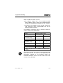
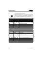
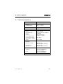
The address assignment when a field bus module is
used is shown in the table below.
Module
Maximum address range
-
1)
I0.0 ...I0.9
1)
Q0.0 ... Q0.7
1)
I/O modules on first
axis interface string
I1.0 ... I1.15
Q1.0 ... Q1.15
First I/O module
I2.0 ... I2.9
Q2.0 ... Q2.7
I/O modules on second
axis interface string
I3.0 ... I3.15
Q3.0 ... Q3.15
Second I/O module
I4.0 ... I4.9
Q4.0 ... Q4.7
Third I/O module
I5.0 ... I5.9
Q5.0 ... Q5.7
Field bus module
I10.0 ... I13.15
Q10.0 ... Q13.15
1) Address range 0.0 ... 0.15 is not available if a field bus module
is used
The functions of the internal input and output bits of the
field bus module, as well as the permitted NC
commands, depend on the operating mode set.
Detailed information on this can be found in the user
manual for the SPC200.
SPC200-COM-IBS 0503a
1-9