1
®
USER MANUAL
Version 09/06
© Copyright 2006 Incredible Technologies, Inc. All Rights Reserved.
WARNINGS AND NOTICES
NOTICE
This game is intended to be operated for amusement purposes only. It is not to be operated in violation of any federal, state, or local
laws or regulations. As the owner and/or operator of this game you are responsible for its operation in compliance with such laws
and regulations. The factory settings for this game may require adjustment in order to comply with the laws and/or regulations in the
jurisdiction where the game is located. It is the sole responsibility of the operator to determine what laws and/or regulations are
applicable and to make any adjustments to the game before operating it for its intended purpose.
NOTICE
This manual and the information contained within is subject to change without notice.
WARNING
Use of unauthorized parts or making any unauthorized modifications will void the warranty and may result in the game operating in
an unsafe or incorrect manner.
WARRANTY, REPAIR, AND RETURN POLICY
•
90-day warranty on all electronic components. All warranty periods begin on the date of purchase from Incredible
Technologies, Inc.
•
There is a minimum $75.00 service charge for all non-warranty repairs or returns.
•
For all servicing, return to Incredible Technologies, Inc.
•
ANY non-factory repair or attempted repair voids warranty.
RETURN MERCHANDISE AUTHORIZATION
•
All returned merchandise must have a Return Merchandise Authorization (RMA) number marked clearly on the outside of the
package.
•
You must obtain all RMA numbers from Incredible Technologies. Please have the product's Cabinet Identification Device
number available when calling for an RMA number.
•
Merchandise returned without an RMA number will not be accepted.
•
Warranty may be void if serial number or security labels are tampered with or removed. Opening the Nighthawk Chassis
system will void your warranty.
•
Advance replacement hardware will be shipped to the customer address on file unless specified otherwise.
•
Advance replacement hardware will be billed to the customer until Incredible Technologies, Inc. receives the returned
merchandise, at which time a credit will be issued.
•
All repairs and/or replacements will ship as soon as possible after receipt or request (subject to availability).
If the original purchaser discovers any physical defect in the media (disk, EPROM, tape) on which the software is distributed or in
the documentation, which in the opinion of Incredible Technologies, Inc. (IT) prevents the product from being used as reasonably
intended, IT will replace the media or documentation at no charge. The purchaser must return the item to be replaced, with proof of
purchase, to IT within 90 days after taking delivery of the software.
IT warrants to the original purchaser that the hardware product is in good working condition for a period of 90 days from taking
delivery of the product. Should this product, in IT's opinion, malfunction within the warranty period because of a defect in design,
materials, or workmanship, IT will repair or replace this product without charge under the terms as follows. Replacement of either
the hardware product or its component parts will be only on an exchange basis. Any replaced parts or components become the
property of IT. This warranty does not apply to those products that have been damaged due to accident, abuse, improper
installation, natural disaster, or unauthorized repairs or modifications.
IT excludes any and all implied warranties, including warranties of merchantability and fitness for a particular purpose, and limits the
purchaser's remedy to returning the software, hardware, or documentation to IT for replacement.
IT makes no warranty or representation, either express or implied, with respect to this software, hardware, or documentation, their
quality, performance, merchantability, or fitness for a particular purpose. This software, hardware, and documentation are licensed
"as is," and the purchaser/licensee assumes the entire risk as to their quality and performance.
In no event will IT be liable for direct, indirect, special, incidental, or consequential damages arising out of the use or inability to use
the software, hardware, or documentation, even if advised of the possibility of such damages. The warranty and remedies set forth
above are exclusive and in lieu of all others, oral or written, express or implied. No person, seller, dealer, agent, or employee is
authorized to make any modification or addition to this limited warranty.
Some states do not allow the exclusion of implied warranties or liability for incidental or consequential damages, so the above
limitation or exclusion may not apply to you. This warranty gives you specific legal rights, and you may also have other rights that
vary from state to state.
- INCREDIBLE TECHNOLOGIES, INC
GOLDEN TEE® LIVE, ITS®, INCREDIBLE TECHNOLOGIES®, IT®, ITNet®, and IT incredible TECHNOLOGIES® are the properties of Incredible
Technologies, Inc. All Rights Reserved.
© Copyright 2006 Incredible Technologies, Inc. All Rights Reserved. Unauthorized duplication is a violation of applicable law.
All other marks are the properties of their respective owners. All rights reserved.
®
Golden Tee LIVE USER MANUAL
TABLE OF CONTENTS
TABLE OF CONTENTS .................................................................................................................................... 1
DEDICATED CABINET ....................................................................................................................................... 5
Step 1: Dedicated Cabinet Contents ................................................................................................................ 5
Step 2: Marquee Header................................................................................................................................... 5
Step 3: Leg Leveler Installation and Adjustment ................................................................................................ 5
Step 4: Apply Power......................................................................................................................................... 6
Step 5: ITNet® Registration............................................................................................................................... 7
Dedicated Cabinet Repair Procedures........................................................................................................... 8
System Chassis Box......................................................................................................................................... 8
I/O Board.......................................................................................................................................................... 9
Antenna............................................................................................................................................................ 9
Cabinet Identification Device (CID) ................................................................................................................. 10
Cash Vault...................................................................................................................................................... 10
Card Reader................................................................................................................................................... 11
Control Panel.................................................................................................................................................. 12
Cabinet Bezel................................................................................................................................................. 13
Lighted Marquee............................................................................................................................................. 14
Fluorescent Light Fixture ................................................................................................................................ 14
Speakers........................................................................................................................................................ 14
27” Monitor..................................................................................................................................................... 15
LCD Monitor................................................................................................................................................... 16
I/O Dip Switch Settings ................................................................................................................................... 16
General Cabinet Maintenance ...................................................................................................................... 17
General Cabinet Maintenance ........................................................................................................................ 17
Care and Cleaning of Rubber Bumper ............................................................................................................ 17
Nighthawk Air Filter ........................................................................................................................................ 17
Trackball Maintenance.................................................................................................................................... 17
Care and Cleaning of Cooling Fans and Vents................................................................................................ 17
LCD Monitor Care and Cleaning ..................................................................................................................... 17
RETROFIT KIT INSTALLATION........................................................................................................................ 19
Step 1: Retrofit Kit Contents............................................................................................................................ 19
Step 2: Recommended Tools.......................................................................................................................... 20
Step 3: Installation Preparation....................................................................................................................... 20
Step 4: Preparing the Cabinet for Installation.................................................................................................. 21
Step 5: Retrofit Kit Component Installation...................................................................................................... 24
Step 6: Apply Power....................................................................................................................................... 31
Step 7: ITNet® Registration............................................................................................................................. 32
General Cabinet Maintenance ...................................................................................................................... 33
General Cabinet Maintenance ........................................................................................................................ 33
Trackball Maintenance.................................................................................................................................... 33
Care and Cleaning of Cooling Fans and Vents................................................................................................ 33
Nighthawk Air Filter ........................................................................................................................................ 33
LCD Monitor Care and Cleaning ..................................................................................................................... 33
Antenna Adjustment ....................................................................................................................................... 33
Golden Tee LIVE™
Version 09/06
© Copyright 2006 Incredible Technologies, Inc. All Rights Reserved. Unauthorized duplication is a violation of applicable law.
All other marks are the properties of their respective owners. All rights reserved.
Page 1
STANDARD ONLINE AND BASIC OFFLINE Kit Contents.............................................................................. 35
Kit Installation ................................................................................................................................................. 36
Recomme nded Tools...................................................................................................................................... 36
Installation Preparation................................................................................................................................... 36
Preparing The Cabinet.................................................................................................................................. 37
Cabinet Selection ........................................................................................................................................... 37
Preparing the Cabinet for Installation.............................................................................................................. 37
Check JAMMA Harness and Wiring ................................................................................................................ 37
Check Coin Mechs and Bill Acceptor .............................................................................................................. 37
Check Coin Door Connections........................................................................................................................ 37
Check Monitor ................................................................................................................................................ 38
Remove Cabinet Graphics.............................................................................................................................. 38
Remove Existing Card Reader (If applicable).................................................................................................. 38
CUT Hole for Card Reader (Online Kit Only) ................................................................................................... 39
Bore Hole for Fan........................................................................................................................................... 39
Vacuum Cabinet Thoroughly........................................................................................................................... 39
Electronics Installation................................................................................................................................. 39
Install Cooling Fan.......................................................................................................................................... 39
Install Card Reader (Online Kit Only) .............................................................................................................. 39
Install Nighthawk Chassis ............................................................................................................................... 40
Install Cabinet Identification Device (CID) ....................................................................................................... 40
Install I/O Board.............................................................................................................................................. 41
Install Antenna (Online Kit Only) ..................................................................................................................... 41
Control Panel Installation ................................................................................................................................ 41
Install Optional Control Panel for Golden Tee Fore! Cabinets.......................................................................... 41
Trackball and Button Preparation (For Most Kits)............................................................................................ 42
Control Panel Overlay Installation................................................................................................................... 43
Finishing The Control Panel............................................................................................................................ 44
Complete Nighthawk Chassis Connections ................................................................................................ 45
Attach I/O Power, Audio, and USB cables....................................................................................................... 45
Attach Main Video Cable ................................................................................................................................ 45
Attach Power Cable ........................................................................................................................................ 45
Soft Power / Fan Cable................................................................................................................................... 45
Complete I/O Board Connections.................................................................................................................... 46
Connect JAMMA Harness............................................................................................................................... 46
Connect the Control Panel Switches and Cable .............................................................................................. 46
Connect New Buttons ..................................................................................................................................... 46
Connect Coin Door Lamps.............................................................................................................................. 46
Connect the Trackball..................................................................................................................................... 46
Connect Antenna ............................................................................................................................................ 46
Connect Audio Cables .................................................................................................................................... 46
Connect the USB Cable.................................................................................................................................. 46
Connect Medium or Low Resolution Monitor................................................................................................... 46
Connect VGA or SVGA Monitor ...................................................................................................................... 46
Connect I/O Power Cable ............................................................................................................................... 46
Check All Connections.................................................................................................................................... 46
Cabinet Graphics Installation....................................................................................................................... 47
Side Decal Installation.................................................................................................................................... 47
Marquee Installation ....................................................................................................................................... 47
Coin Doors, Test Switch, and Volume Controls ............................................................................................... 48
Initial Power-Up .............................................................................................................................................. 48
GOLDEN TEE LIVE SYSTEM SETUP MENUS.................................................................................................. 49
Navigating The Menu System......................................................................................................................... 49
Entering System Setup Mode ......................................................................................................................... 49
Selecting a Menu............................................................................................................................................ 49
Choosing a Menu/Option ................................................................................................................................ 49
Changing a Value ........................................................................................................................................... 49
Main Menu..................................................................................................................................................... 49
Collections & Earnings Menu....................................................................................................................... 50
Do Collection.................................................................................................................................................. 50
Golden Tee LIVE™
Version 09/06
© Copyright 2006 Incredible Technologies, Inc. All Rights Reserved. Unauthorized duplication is a violation of applicable law.
All other marks are the properties of their respective owners. All rights reserved.
Page 2
General Settings........................................................................................................................................... 51
Operator Adjustables...................................................................................................................................... 52
General Adjustments ...................................................................................................................................... 52
Money Slot Adjustments ................................................................................................................................. 53
Sound Adjustments ........................................................................................................................................ 53
Collection Settings.......................................................................................................................................... 54
Reset to Factory Settings................................................................................................................................ 55
System Tests.................................................................................................................................................. 56
Video Tests .................................................................................................................................................... 56
Color Adjustments .......................................................................................................................................... 57
Contrast Adjustments ..................................................................................................................................... 57
Screen Size Adjustment.................................................................................................................................. 58
Sound Tests................................................................................................................................................... 58
Player Control Tests....................................................................................................................................... 58
Mechanical Meter Test ................................................................................................................................... 59
Hardware Tests.............................................................................................................................................. 59
Hardware/Software......................................................................................................................................... 59
System Info .................................................................................................................................................... 60
USB Info......................................................................................................................................................... 60
Version Info.................................................................................................................................................... 60
Check Hard Drive ........................................................................................................................................... 61
Check Cooling ................................................................................................................................................ 61
Check Card Reader (online only) .................................................................................................................... 61
Troubleshooting Shortcuts .......................................................................................................................... 62
Golden Tee Settings & Audits...................................................................................................................... 62
Golden Tee Settings ....................................................................................................................................... 63
Golden Tee Audits.......................................................................................................................................... 63
Player Cost Schedule ..................................................................................................................................... 64
ITNet Settings (online only).......................................................................................................................... 65
Change Location ............................................................................................................................................ 65
Communication Settings ................................................................................................................................. 66
Configure Ethernet Settings ............................................................................................................................ 66
Connection Tests............................................................................................................................................ 67
Re-Activate Modem........................................................................................................................................ 67
GOLDEN TEE LIVE TROUBLESHOOTING & REFERENCE............................................................................. 69
Appendix A Troubleshooting Guide............................................................................................................ 69
Appendix B JAMMA, Trackball, and I/O Power Connections ..................................................................... 74
Appendix C Replacement Part Numbers..................................................................................................... 75
Appendix D System Diagrams ..................................................................................................................... 78
Appendix E GNU General Public License.................................................................................................... 87
Appendix F Informational Guides................................................................................................................ 89
Wireless Signal Strength and Antenna Guide.................................................................................................. 89
Collections Guide ........................................................................................................................................... 90
Income Split Guide ......................................................................................................................................... 91
Player Accounts Guide ................................................................................................................................... 92
Golden Tee LIVE Revenue Guide ................................................................................................................... 93
Accounting for the Various Revenue Types..................................................................................................... 93
Golden Tee LIVE Fees ................................................................................................................................... 94
Accounting for Fees........................................................................................................................................ 95
Collections...................................................................................................................................................... 95
Collection Worksheet...................................................................................................................................... 96
GT LIVE Collection Procedure ........................................................................................................................ 97
Menu Navigation Shortcuts........................................................................................................................... 100
Appendix G ITNet Registration Forms....................................................................................................... 101
ITNet DEBIT ACCOUNT FORM.................................................................................................................... 101
ITNet GAME REGISTRATION FORM........................................................................................................... 103
ITNet OPERATOR AGREEMENT................................................................................................................. 105
Golden Tee LIVE™
Version 09/06
© Copyright 2006 Incredible Technologies, Inc. All Rights Reserved. Unauthorized duplication is a violation of applicable law.
All other marks are the properties of their respective owners. All rights reserved.
Page 3
APPENDIX H Mounting Templates............................................................................................................. 109
Trackball Orientation Diagram ...................................................................................................................... 109
Trackball Mounting Template........................................................................................................................ 111
Button Templates ......................................................................................................................................... 113
Card Reader Mounting Template A............................................................................................................... 117
Card Reader Mounting Template B............................................................................................................... 118
Fan Hole Template ....................................................................................................................................... 118
NOTE
PLEASE RETAIN ORIGINAL SHIPPING BOX FOR SERVICE AND REPAIR.
NOTE:
This kit is designed for use in cabinets with a JAMMA cable and wiring installed.
If you do not have a JAMMA harness already installed in the cabinet you have selected
and are wiring the cabinet yourself, refer to the JAMMA Wiring Diagram in Appendix B.
NOTE:
Do NOT install this kit when the cabinet is powered on. Make sure the cabinet is
unplugged from all power sources before and during installation.
Golden Tee LIVE™
Version 09/06
© Copyright 2006 Incredible Technologies, Inc. All Rights Reserved. Unauthorized duplication is a violation of applicable law.
All other marks are the properties of their respective owners. All rights reserved.
Page 4
DEDICATED CABINET
STEP 1:
DEDICATED CABINET CONTENTS
Dedicated Parts List
(1) Golden Tee LIVE Dedicated Cabinet
Shipped inside a separate box labeled Parts – Do Not Discard within the cabinet packaging.
(1) Marquee Header
Shipped inside the coin tray:
(1) Power Cord
(2) Rear Leg Levelers, shipped inside the coin tray.
Shipped inside the vinyl pocket attached to the inside of the back door:
(1) Golden Tee LIVE Manual
(1) Monitor Manual
(1) DBV/Coin Door Manual and Extra Parts
(1) T-15 Torx Tamper-Resistant Wrench
(1) T-20 Torx Tamper-Resistant Wrench
(1) T-25 Torx Tamper-Resistant Wrench
(2) ¼-20 Bolts for Marquee Header
If any parts to your dedicated cabinet are missing/damaged please contact Incredible Technologies Technical
Support at 847-870-7027 x121.
STEP 2:
MARQUEE HEADER
Your dedicated cabinet requires some simple assembly before it is ready to be placed on location. Please follow
these steps to install the marquee header. The header is shipped inside a separate box labeled Parts – Do Not
Discard within the cabinet packaging. The box is located outside of the cabinet directly under the cash vault.
Marquee Header Installation
First, remove the two center Philips head screws that secure the
access/mounting plate for the marquee fluorescent light fixture, and
loosen the four outside Phillips head screws, but do not remove them.
Remove the plate and light fixture and set-aside for now. Remove the
bolts from the holes in the top of the cabinet. Place the marquee
header on top of the cabinet and align it with the mounting holes
located at the top of the cabinet. Secure to the top of the cabinet with
the bolts. Once secure, connect the power cable from the header to
the mating connector located at the access hole on the cabinet.
Reinstall the access/mounting plate by placing it over the outside four
screws. Reinstall the two center screws, and tighten all six screws.
STEP 3:
LEG LEVELER INSTALLATION AND ADJUSTMENT
Once your game is in position at the location, it is necessary to install and adjust the leg levelers. The leg levelers
will help stabilize the game on an uneven floor, and help it from moving or shifting during game play. The game is
shipped with the two front leg levelers installed. You will need 2 people to install the rear leg levelers. One
person must carefully tip the game either forward or to one side to expose the threaded inserts located on the
bottom rear of the cabinet. While tipped up, carefully thread the leg levelers into place. Adjust the levelers as
necessary to level and stabilize the game.
Golden Tee LIVE™
Version 09/06
© Copyright 2006 Incredible Technologies, Inc. All Rights Reserved. Unauthorized duplication is a violation of applicable law.
All other marks are the properties of their respective owners. All rights reserved.
Page 5
STEP 4:
APPLY POWER
Locate the power cord, shipped inside a small box inside the cardboard carton. Connect the power cable to the
plug on the back of the cabinet. Then plug the cable into a 3-pronged, grounded wall socket. Locate the power
switch on the back of the cabinet and turn it on.
Watch the game carefully when you first turn it on. Look and smell for smoke (TURN IT OFF IMMEDIATELY IF
ANY IS NOTICED). Make sure the fan inside the chassis is running and the LED’s on the I/O board in back are
flashing. If not, something is wrong, turn off the game.
Check the Cabinet ID Device (CID) Number
Watch the screen during boot-up and wait for an orange verification screen to appear. Note the Cabinet ID
Number (CID) that appears on this screen, and verify that it matches the CID number printed on the back of the
cabinet. The screen will automatically time out and boot-up will continue.
Check the Coin Switch and Bill Validator
Try the coin switch. Drop quarters or tokens through to check the coin mech. Insert a dollar bill into the bill
validator and listen for the credits to ring up. Make sure the game is adding credits and the correct quantity. You
can use the PLAYER CONTROL TEST by pressing the System Setup button inside the coin door and entering
the SYSTEM TESTS MENU. Make sure all of the controls work.
Checking the Wireless Connection Signal Strength
There are two ways to check the signal strength of your Golden Tee LIVE test machine.
First, you can power the game off and on. A signal meter will appear in the lower right
corner of the game’s boot-up screen. The number of bars that are displayed indicate the
signal strength. Additionally, you can enter Operator Mode by pressing the System Setup
button inside the coin vault door. Once at the main Operator Mode menu, use the trackball
and Start button to select ITNet Settings, then Communication Settings to view more
information.
Cabinet Temperature
The state of the art Nighthawk hardware is extremely powerful, and therefore generates a
substantial amount of heat. Measures have been taken to keep the various components
cool during normal use. If overheating occurs, game play and hardware longevity may be
affected. Use the Check Cooling menu in the System Setup menus to monitor the
temperature within your cabinet. Enter System Setup by pressing the System Setup button
inside the outer door of the coin vault. Once at the main System Setup menu, use the
trackball and Start button to select Troubleshooting/Info, then Check Cooling.
Custom Adjustments
Upon initial power-up, the game will initialize to factory default settings. These settings affect game elements such
as number of credits per coin, volume settings, etc. The System Setup section will describe how to alter these
settings and view the system audits or run system tests.
Golden Tee LIVE™
Version 09/06
© Copyright 2006 Incredible Technologies, Inc. All Rights Reserved. Unauthorized duplication is a violation of applicable law.
All other marks are the properties of their respective owners. All rights reserved.
Page 6
STEP 5:
ITNET® REGISTRATION
Golden Tee LIVE is an online only game, and must be properly registered to ITNet for all of the game features to
be available. First you must register with ITNet as an ITNet Operator. Once you are established as an ITNet
Operator, you can register your game to receive the online features.
ITNet® Operator Registration
Follow these simple instructions to become eligible for ITNet® online features.
1. Fill out the ITNet® Debit Account Form, found in Appendix G, and open a Debit Account at your local bank.
2. Read and sign the ITNet® Operator Agreement, found in Appendix G at the back of this manual.
3. Fax or mail these two forms to Incredible Technologies, Inc. at (847) 454-9156 to become an authorized
ITNet® Operator.
4. Once these forms are processed, you will receive your ITNet® Operator ID Card in the mail.
The Operator ID Card allows you to:
Register your games for online play right on-site.
Activate games, add and change location information, and de-activate games at the location.
Gain access to the personalized IT Operator Services web site.
Check audits, bookkeeping and game play statistics and make game adjustments from your home or office.
NOTE:
If you are a brand new ITNet® operator and can’t wait for your Operator ID card to arrive in the mail, you can fax the GAME
REGISTRATION FORM, found in Appendix G, to Incredible Technologies. The ITNet® staff will then enter your machine’s
location data for you. Please allow 2 to 5 business days for processing. When your machine connects with ITNet, it will
automatically register to your account and activate the online features.
ITNet® Game Registration
Follow these simple instructions for game and ITNet setup.
Follow the instructions above to become an ITNet operator and receive your Operator ID card. You can use the
card to register your games on site, or you can submit a Game Registration Form to complete game registration.
Game Registration Form
1. Fill out the Game Registration Form found in Appendix G. Be sure all of the information is correct and legible.
Make sure to include the Cabinet Identification Device (CID) number.
2. Fax or mail the Game Registration Form to Incredible Technologies for processing. Forms are usually
processed within 3 days, but please allow up to 10 business days for complete registration.
3. Your game will be automatically registered once the form has been processed, and should enable online
features automatically. Online features may take up to four hours to appear on the game.
On-Site Registration
1. Turn on the game. You may have to wait a few seconds for hard drive access. If the game is not registered a
screen will appear asking you to swipe your operator card to start the registration process. If you do not have
your card, or do not have it ready, the screen will time out after 4 or 5 minutes.
2. Enter all of the necessary location information carefully and accurately. When completed, the game will
automatically attempt to connect to ITNet.
3. If registration is successful, the game will switch directly to the attract mode. If there was any trouble with the
connection to ITNet, an error message will appear. Select Yes to try to connect again. If your first few
attempts to connect are unsuccessful, refer to the troubleshooting guide in Appendix A of this manual or call
IT tech service at 847-870-7027 x121.
4. The game is now connected to the ITNet System and ready for public play! Online features will be
automatically activated by Incredible Technologies, and some may take up to four hours to be received.
Golden Tee LIVE™
Version 09/06
© Copyright 2006 Incredible Technologies, Inc. All Rights Reserved. Unauthorized duplication is a violation of applicable law.
All other marks are the properties of their respective owners. All rights reserved.
Page 7
DEDICATED CABINET REPAIR PROCEDURES
SYSTEM CHASSIS BOX
The Nighthawk Chassis houses most of the game electronics and hardware in one box that can be easily
installed. As with all electronic equipment, the Chassis box should be handled with extreme care. Shock, severe
temperature, or sudden impacts can damage the internal components that require costly repair.
Note!
Turn off power to the cabinet when performing any of the following.
System Chassis Removal
1. Disconnect all connections to the system box. Be sure all wires and connectors are clear and out of the way.
Label the connectors for easy reconnection.
2. Remove the lower 4 wood screws that secure the system box to the cabinet’s mounting panel.
3. Support the system box against the mounting panel. Remove the 2 3/8” nuts from the mounting studs and lift
the system box out of the cabinet.
System Chassis Installation
1. Align the system box onto the top two mounting studs of the panel. The connection ports face up. Install and
secure the two 3/8” nuts to the mounting studs first. Next install and secure the 4 lower wood screws.
2. Connect the required connections. See the Connections Diagram in Appendix D for more details.
Golden Tee LIVE™
Version 09/06
© Copyright 2006 Incredible Technologies, Inc. All Rights Reserved. Unauthorized duplication is a violation of applicable law.
All other marks are the properties of their respective owners. All rights reserved.
Page 8
I/O BOARD
NOTE!
The I/O board is game title specific and is not interchangeable with other game titles produced by Incredible Technologies on this
system. Dedicated and Retrofit Kit I/O boards are different and are not interchangeable.
Dedicated I/O Board Removal
First, disconnect all connections from the I/O board. Refer to the I/O board
connections diagram below. Label the connectors for easy reconnection
and move them safely out of the way. Next, remove the four ¼” wood
screws that secure the board to the left inside wall of the cabinet. Carefully
remove the I/O board from the cabinet.
Dedicated I/O Board Installation
Place the I/O board in the proper location inside the cabinet. Be sure it is
oriented properly so the cables reach the board. Secure the I/O board to
the side of the cabinet with the four ¼” wood screws. Use the same
mounting holes if at all possible. Be sure the board does not “bow” or is not
stressed in any way. Once mounted, connect the appropriate connectors.
Refer to the Dedicated I/O board connection diagram below.
ANTENNA
The antenna connects to the I/O Board and is mounted in a housing on the back of the cabinet. A strong wireless
signal is very important to getting the most out of your game. Depending on the positioning of the game in the
location, you may need to adjust the antenna’s position to achieve the best signal. The antenna’s housing allows
for a variety of positions within, and the housing itself can be easily moved to a different location using tape or
screws. See the Wireless Signal Strength and Antenna Guide found in Appendix F for more information on
getting the best possible wireless signal strength for your game.
Golden Tee LIVE™
Version 09/06
© Copyright 2006 Incredible Technologies, Inc. All Rights Reserved. Unauthorized duplication is a violation of applicable law.
All other marks are the properties of their respective owners. All rights reserved.
Page 9
CABINET IDENTIFICATION DEVICE
(CID)
This device contains a specific ID number that identifies
your cabinet. The CID is a permanent number and
must be connected to the main system box via the USB
cable and working properly in order for the game to
operate.
CID Removal and Replacement
If for some reason you must replace the CID,
disconnect the USB cable from the CID. This is
the only connection to the CID. Next, remove
the two ¼” wood screws that secure the CID
to the right inside of the cabinet.
To install a CID, reverse the order above.
Note!
The Cabinet Identification Device should NEVER be removed from the cabinet, even when replacing any of the other components.
The CID is the cabinet’s PERMANENT Identifier, regardless of any other components.
CASH VAULT
The Cash Vault has been designed for optimal security. With the double-locking doors, service technicians can
read meters and enter System Setup mode with no access to the cash box.
Cash Vault Removal and Replacement
1) Unlock and open the outer door of the Cash Vault.
2) Using a T-15 Torx wrench, unscrew the card reader/button plate located on the right side by removing the
four #8-32 screws located at the top and bottom of the plate.
3) Unplug the cable from the card reader, and disconnect the connectors for the coin meter and buttons.
4) Remove the plate and set it aside.
5) Remove the coin bin and the bill validator magazine to make it easier to work inside the vault.
6) Unplug the bill validator cables, and push the cables for the bill validator, card reader, buttons, and coin meter
through the 2 holes located in the back of the vault.
7) The Cash Vault is attached by upper and lower locking brackets. These are each attached with two sockethead screws located within the vault.
8) Locate the socket-head screws on the top and bottom locking brackets. Remove the two bottom screws
using a 9/64” hex key and remove the bottom locking bracket. Make sure to note how it was installed.
9) Remove the two top screws and remove the top locking bracket, again noting how it was installed.
10) You can now pull the entire vault assembly out from the front of the cabinet. The vault is attached with foam
tape, so it will need to be pried out or pushed from behind to loosen the adhesive.
11) Reverse the procedure to install the new door.
Locks
The outer lock is a secure T-handle lock, commonly used in vending. To open, insert the key and turn it
clockwise until the lock-handle pops out. Next, rotate the lock-handle clockwise 90 degrees to open the outer
door.
The inner door has a lock installed above the System Setup button. This lock is unlocked by turning the key 90
degrees clockwise.
Volume and Service Buttons
Mounted inside the outer door are controls for Volume and System Setup. Press the Volume Up button to
increase the loudness of the sounds on the game, and press the Volume Down button to make your game
quieter. Press the System Setup button to access the game’s software menu system. The System Setup menus
cover a variety of important areas including collections, tests, game adjustments, and optional settings. System
Setup is covered in detail starting on page 49.
Golden Tee LIVE™
Version 09/06
© Copyright 2006 Incredible Technologies, Inc. All Rights Reserved. Unauthorized duplication is a violation of applicable law.
All other marks are the properties of their respective owners. All rights reserved.
Page 10
Bill Acceptor
The dedicated cabinet ships with a MARS AE2681 D5 bill acceptor and is mounted on the cash vault door. The
default dipswitch settings for this acceptor are ON = 1,2,4-7 and OFF = 3,8.
Bill Acceptor Removal
Disconnect the cable to the bill acceptor. Remove the four 11/32” sized nuts from the mounting studs.
Disconnect the ground wire from the one lower stud. Then gently pull the accepter off the studs from the back
side of the coin door.
Bill Acceptor Installation
From the back side of the coin door, place the bill acceptor onto the four mounting studs. The faceplate will
protrude out the front of the coin door. Place the field ground wire on a lower stud, and install the four 11/32”
sized nuts on the mounting studs and tighten. Next, connect the bill acceptor cable in the cabinet to the mating
cable on the bill acceptor itself.
Stacker Removal
A blue slide switch is located at the bottom of the stacker. Engaging it allows the stacker to be removed.
Coin Mech
Coin Mech Removal
Loosen the two finger screws to release the securing braces. Slide the upper brace upward, and the lower brace
downward. The mechanism should pull straight out.
Meter
This 5-volt device is mounted behind the card reader plate next to the inner door of the coin vault. One lead of
the meter is connected to a +5 volt source and the other lead is connected to the appropriate signal wire. See
wiring diagram on page 81. An additional opening is available just below the meter, if a second meter is desired.
CARD READER
The Card Reader is a very important aspect to Golden Tee LIVE, and is
very important to keep in good working condition. Players are required
to use a card to identify themselves for most of the online features. If
the card reader is not working properly, these features will not be
available.
Card Reader Removal
Access the card reader through the coin door opening. To remove the
card reader, disconnect the USB connector from the Card Reader.
Then remove the 4 T-15 security screws that secure the mounting panel
that holds the card reader, coin counter and buttons. Next, remove the
two Phillips head screws holding the card reader to the mounting panel.
Once loose, pull the card reader out through the front of the panel.
Card Reader Installation
Open the coin door to access the card reader mounting. Place the back
end of the card reader through the opening on the mounting panel. The
larger portion of the card reader bezel should be in the up position.
From the backside of the panel, secure the card reader to the panel
with the 2 Phillips head screws. Once in place, reconnect the USB
cable to the card reader. Attach the mounting panel to the coin door
with the 4 T-15 security screws. Power the game back on and test the
card reader using the Card Reader Test located in the
Troubleshooting/Info Menu in System Setup.
Golden Tee LIVE™
Version 09/06
© Copyright 2006 Incredible Technologies, Inc. All Rights Reserved. Unauthorized duplication is a violation of applicable law.
All other marks are the properties of their respective owners. All rights reserved.
Page 11
CONTROL PANEL
Opening the control panel provides access to the trackball and buttons, as well as the controls for adjusting both
color monitors. To open the control panel, locate and remove the two T-25 security screws on either side of the
cabinet. A T-25 Torx wrench has been provided in the vinyl pocket on the back door. Remove the screws
completely before opening the control panel. Once the screws have been removed, store them in a safe place
and then lift the hinged control panel from the top, where the control panel meets the plastic bezel.
Monitor Adjustments (LCD and 27” CRT)
There are two small boards located beneath the control panel that are used to adjust your monitors. These
controls are placed here so you can view both monitors when making corrections to color, brightness or size. Use
the Monitor Test screens in System Setup for best results.
Software Update Connections
A power cord and USB connector are supplied under the control panel, in anticipation of software updates via a
DVD drive. When a software update is available, you can conveniently connect your compatible DVD drive with
no additional equipment needed.
Note!
Some DVD drives do not have a mating AC power connector and will require an alternative AC power source.
Soft Power Switch
A “soft power” switch has been added beneath the control panel, to assist in the update process. This switch will
turn off power to the cabinet so you don’t have to reach around to the main power switch located on the back of
the cabinet.
Note!
If you turn power off using the Soft Power Switch, you must use this same switch when turning power back on.
Trackball Replacement
To replace a trackball, open the control panel and remove the 4 long screws holding the trackball in place. Be
careful not to lose any of the screws, washers and lock washers. Disconnect the wire harness and ground wire
and remove the old trackball. Position the new trackball in the proper orientation over the existing standoffs.
Make sure that the arrow on the trackball that points to the monitor is pointing up. Replace the 4 long screws and
washers. Do not over tighten! Screw in until the lock washer is fully compressed. Reconnect the wiring
connector and ground wire.
Note!
The field ground wire is critical to avoid electrical problems and assure optimal performance.
Button Replacement
All of the buttons on the control panel require a 1 1/8 th inch hole, and are pre-drilled on the dedicated control
panel. To remove a button, disconnect the wires from the button assembly by sliding the wires off of the micro
switch posts. Next carefully twist the micro-switch assembly off of the button posts. Finally, unscrew the nut to
remove the button from the control panel.
Place the new button assembly into the hole and position the smaller side of the micro-switch housing to face the
rubber bumper, angled towards the middle. Tighten the supplied nut using a pushbutton wrench. Do not over
tighten. Install the micro-switch by snapping it onto the pushbutton assembly by hand. Position the assembly so
the micro switch posts face the rubber bumper, angling towards the middle. Reconnect the wires by sliding the
wire assembly onto the contact posts of the appropriate micro switch. See the wiring diagrams in the back of this
manual.
Golden Tee LIVE™
Version 09/06
© Copyright 2006 Incredible Technologies, Inc. All Rights Reserved. Unauthorized duplication is a violation of applicable law.
All other marks are the properties of their respective owners. All rights reserved.
Page 12
L.E.D. Lighted Buttons
The Help and Options buttons on Golden Tee LIVE are Light Emitting Diode buttons. The housing
for the L.E.D. snaps into the back of the button assembly. The L.E.D. must be installed properly
for the light to function properly. The Anode/positive side of the L.E.D. is connected to the +5
volts, and the Cathode/negative side of the L.E.D. is connected to the appropriate signal wire. The
L.E.D. slides into the housing and the housing is marked Positive and Negative. See the lamps
connector J202 in the cabinet wiring diagram in Appendix D.
Control Panel Removal
To remove the control panel from its hinge, Disconnect the trackball cable, field-ground wire, and
the control panel interconnect connector to the I/O board. Remove the screw that attaches the
safety cable to the control panel. Remove the four ¼” screws holding the panel to the hinge.
Control Panel Graphics Removal
The control panel artwork has been screened onto a solid sheet of polycarbonate, which is resistant to scratches
and burns. Unfortunately long exposure to excessive situations may damage the surface over time. To remove
and replace this piece, the pushbutton assemblies must first be removed. Next, remove the 4 T-20 security
screws from the four corners of the panel. A T-20 Torx wrench has been included and ships inside the pocket on
the back door. Separate the polycarbonate piece from the wood portion of the panel by starting at one corner and
slowly peeling the two apart. The overlay has adhesive on the entire surface and will take some force to separate
the pieces due to the adhesive. Once removed, the graphic overlay will not be able to be used again.
Control Panel Graphics Installation
To install a new polycarbonate Graphics overlay, make sure the wood control panel surface is clean, smooth, and
free from dirt and debris. Remove the paper protecting the adhesive from the new artwork/cover panel. Carefully
place it on the wood panel, aligning it properly. Press and smooth firmly to assure that it is secure. Install the 4
security screws in each corner of the panel. Be sure they are flush or below the surface to prevent injury.
Replace the buttons in the correct orientation.
CABINET BEZEL
The molded bezel on the front of the Golden Tee LIVE
cabinet is used to mount and secure a number of
components. This bezel will need to be removed to gain
access to the speakers, 27” monitor, and LCD monitor.
Bezel Removal
First, remove the two security screws on either side of the
cabinet that lock down the control panel. The bezel is held
in place with 6 T-25 security screws, 3 on each side of the
cabinet. Remove these screws. A T-25 Torx wrench has
been provided in the pocket on the back door. Once all of
the screws have been removed, lift the hinged control panel
from the top, where the control panel meets the plastic
bezel. Carefully loosen the bezel and pull it out slightly to
allow access to the speaker connectors. Unplug both
connectors. Carefully remove the bezel from the cabinet.
Be careful not to pull on or excessively stress the plastic.
Bezel Installation
With the control panel open, place the bottom of the plastic
bezel into position. Pivot it back far enough so the speaker
connectors can be plugged back in, and do so. Push the
bezel the rest of the way in, being careful not to pinch the
speaker wires. The holes to secure the panel to the
cabinet will align themselves if the bezel is properly placed
into position. Install the 6 security screws, 3 on each side
of the cabinet, to secure the bezel into place. Once the
bezel is installed, close and secure the control panel with the 2 security screws.
Golden Tee LIVE™
Version 09/06
© Copyright 2006 Incredible Technologies, Inc. All Rights Reserved. Unauthorized duplication is a violation of applicable law.
All other marks are the properties of their respective owners. All rights reserved.
Page 13
LIGHTED MARQUEE
Periodically a new version or update for Golden Tee will become available, requiring a new game marquee to be
installed. Follow these directions for removing the existing marquee and replacing it with a new one.
Marquee Installation
First, remove the two center Phillips head screws that secure the access/mounting plate for the marquee
fluorescent light fixture, and loosen the outside four Phillips head screws, but do not remove them. Next remove
the plate and light fixture. Be sure to disconnect the power connector to the light and set it aside. A strong
adhesive on the outer edges of the marquee artwork secures it in place. Carefully peel off the old marquee
artwork.
Marquee Installation
To install the new marquee, first make sure the area where the adhesive is to go is clean and smooth, and free of
dirt and debris. Remove the strips of protective paper on the outer edges to expose the adhesive on the new
marquee. Through the access opening in the back, line up the artwork appropriately and press on the outer
edges to secure the marquee in place. Next, connect the power cable to the mating connector located at the
access hole. Place the plate assembly back over the four Phillips head screws and slide it downward. Reinstall
the two center screws and then tighten all six screws.
FLUORESCENT LIGHT FIXTURE
The Golden Tee LIVE cabinet uses a Happ Controls fixture. The ballast is a clamped core that works with a T8
Lamp - Happ Controls P/N 91-1228-00. The starter is FS2 Deluxe - Happ Controls P/N 91-2000-00. The
Fluorescent bulb is an F15 T8 CW and is easily replaced once the back plate on the marquee header has been
removed. As with all electrical devices, do not work on this component when the power is on.
SPEAKERS
The speakers are mounted on either side of the LCD monitor, so players can best hear the audio. Sounds and
speech are important aspects to the play experience and should be adjusted and maintained for optimal results.
Make sure your speakers are in good working condition, are wired correctly, and are grounded properly to avoid
buzz or hiss.
Speaker Access
In order to reach the speakers, the cabinet bezel must first be removed. Refer to the Bezel Removal section
above. The speakers are located on the back of the bezel. Remove the 4 nuts with an 11/32” nut driver to
remove the speakers from their mounting.
Note:
Both speakers must be identically wired to work properly. For optimal sounds, both speakers must be in phase with one another.
Be sure the positive wire is connected to the positive terminal of each speaker and the negative speaker wire is connected to the
negative terminal of each speaker. See the diagrams in Appendix D.
Golden Tee LIVE™
Version 09/06
© Copyright 2006 Incredible Technologies, Inc. All Rights Reserved. Unauthorized duplication is a violation of applicable law.
All other marks are the properties of their respective owners. All rights reserved.
Page 14
27” MONITOR
Your Golden Tee LIVE cabinet comes equipped with a digital monitor set to SVGA resolution. Golden Tee LIVE
dedicated cabinets support high-res monitors, offering superb graphics and brilliant colors. Additionally, Golden
Tee LIVE supports low-res, mid-res, VGA and SVGA monitors. Make sure the I/O Board and monitor are set
properly for best game play results. The bank of dip switches marked SW201 on the I/O board control video
settings. Refer to the diagram on page 16 for the proper setting for your monitor. Your monitor may require
additional adjustments to set it to the best resolution. Check your monitor’s manual for more information.
Adjustments for color, brightness, contrast and image size are located under the control panel. Refer to the
Control Panel section on page 12 for information on how to access these controls. Monitors are delicate and can
lose color or clarity if not treated properly. Never move a cabinet when the monitor is on. A game with a clear,
bright monitor will attract more players and earn more money than a dim or poorly adjusted monitor.
27” Monitor Removal
To remove the monitor, you first need to open the
control panel and remove the cabinet bezel.
Refer to those sections above for the proper
removal procedures.
1. Once the monitor is exposed, disconnect the
power cable and video connection at the
back of the monitor.
2. The Remote controller board should be rerouted from under the control panel to the
back of the monitor and placed in the
electronics area.
3. Be sure all wires that are not attached to the
monitor are free and clear of the frame. Be
sure that none of the cabinet wires are
attached to the monitor by a connector or
wire ties.
4. From the front, remove the 4 nuts from the
studs of the monitor mounting brackets. Two
of the nuts are located on the top and two are
on the bottom. Do not remove the bolts
holding the tube to the monitor frame.
5. It is best to have two people remove the
monitor from the cabinet. Start with one
person in the back to lift the monitor off the
mounting studs. The second person should
be positioned in front to guide the monitor
out. The person in the back can then join the
person in front to completely remove the
monitor from the cabinet.
27” Monitor Installation
To replace the monitor into the cabinet, make sure all power is off, then open the control panel and remove the
cabinet bezel. Refer to those sections above for the proper removal procedures.
1. Place the monitor into the monitor opening from the front of the cabinet. The electronics on the monitor
should face into the cabinet. It is best to use two people to guide the monitor onto the mounting studs,
located on the mounting brackets inside the cabinet.
2. Install the 4 nuts to secure the monitor to the mounting studs.
3. Route the controller board through the back of the control panel, and to the right side. Secure it with Velcro.
4. Attach the main monitor video cable from the LIVE system box to the video input of the monitor.
5. Attach the power cable to the power input cable of the monitor.
6. Dress cables with wire ties as needed to assure proper routing and reliability.
7. Turn the cabinet on to test the monitor. Adjustments are likely needed. Be sure the dip switches on the I/O
board match the desired resolution. See the monitor’s manual for more details.
Golden Tee LIVE™
Version 09/06
© Copyright 2006 Incredible Technologies, Inc. All Rights Reserved. Unauthorized duplication is a violation of applicable law.
All other marks are the properties of their respective owners. All rights reserved.
Page 15
LCD MONITOR
The LCD monitor is mounted in such a way so that
players view the best possible image. Game
software controls the displayed images so they
appear in the correct orientation. You may see
some text displayed upside down during the bootup process. This is normal.
In order to reach the LCD Monitor, the cabinet
bezel must first be removed. Refer to the Bezel
Removal section on page 13. Once the bezel has
been removed, the LCD monitor is exposed.
LCD Monitor Removal
The remote control board should be pulled from
under the control panel back to the LCD. Remove
the 4 nuts holding the LCD to the mounting
brackets with an 11/32” nut driver. Gently pull the
LCD from the mounting studs. Support the LCD
carefully while you disconnect the video and power
input cables from the back.
Note:
Handle the LCD monitor with care. Do not press on the display or allow anything to lie on top of it. Permanent damage can occur.
LCD Monitor Installation
To install a new LCD monitor, remove the cabinet bezel and carefully connect the video input and power cables to
the LCD monitor. Once connected, set the LCD monitor onto the mounting studs. Fasten the monitor securely
with the 4 nuts. Route the remote adjustment board down through the mouse hole and beside the main monitor,
and finally through the right access hole under the control panel. Secure the remote adjustment board with
Velcro. Be sure the cables are secure. It is best to strain relief the cables with wire ties. Turn on power to the
game and test the monitor to make adjustments as needed.
Note:
Use a soft cloth with an ammonia free glass cleaner to clean the LCD Monitor. Ammonia can ruin the display.
Do not press hard on the display surface. Permanent damage may occur.
I/O DIP SWITCH SETTINGS
Kit
Golden Tee LIVE™
Version 09/06
© Copyright 2006 Incredible Technologies, Inc. All Rights Reserved. Unauthorized duplication is a violation of applicable law.
All other marks are the properties of their respective owners. All rights reserved.
Page 16
GENERAL CABINET MAINTENANCE
GENERAL CABINET MAINTENANCE
Games that are in good working condition, with clear monitors, clean control panels and working trackballs will
make more money than a machine in poor condition. It is definitely worth your time and attention to protect your
investment with a little common care. Each week, clean the 27” monitor and wipe down the control panel to bring
back that new game look. Test the trackball and buttons regularly to make sure they are playing properly. And
perhaps most important, make sure the coin mechs and bill acceptors are in good working order.
CARE AND CLEANING OF RUBBER BUMPER
The rubber bumper on the front of the cabinet’s control panel is made from durable nitrile rubber. Clean it using a
mild soap and water solution or blue window cleaner.
NIGHTHAWK AIR FILTER
The Nighthawk Chassis comes equipped with an external electrostatic air filter. This filter is held in place by a
metal bracket, attached to the chassis. The filter prevents debris from entering the chassis and damaging the
electronic components. A clogged filter will impede airflow, thus building up unwanted heat which can cause
damage to your hardware. Be sure to check this filter at least once a month. Remove the filter by sliding it out of
its housing. Shake off excess dirt and if necessary clean it with soap and water. Be sure the filter is completely
dry before reinstalling the filter.
TRACKBALL MAINTENANCE
The trackball will require periodic maintenance to assure optimum performance. In most cases the inside of the
trackball simply needs to be cleaned of any accumulated dust and debris.
To access the inside of the trackball, remove the 6 Phillips head screws that hold the trackball together and
remove the top cover. Clean out any dust and debris inside the trackball. Polish the rollers and remove any
foreign material that may be on the rollers. Do not lubricate the bearings, as this will only attract more dust. If the
bearings do not spin freely it is best to replace the bearing assembly. Inspect the rollers for any nicks that may
cause poor performance and replace if needed. Inspect the ball for any nicks and replace if needed.
Parts can be obtained from Happ Controls and is an economical option rather than replacing the entire trackball
assembly.
It is critical that the green field ground wire be properly connected to field ground. This prevents the trackball from
building a static charge that can cause the game to lock up or reset. A static discharge can also damage the
trackball’s electronic components, as well as the main system.
CARE AND CLEANING OF COOLING FAN S AND VENTS
The hardware that runs Golden Tee LIVE is quite sophisticated, and many of the chips and processors will get hot
very quickly. Like your desktop PC, the Golden Tee LIVE hardware needs adequate ventilation to work properly.
Dust and dirt can be a major cause to overheating and will lead to costly repairs. At least once a month, check to
make sure the cabinet and chassis fans are working and free of dust and debris. Use a vacuum to clear all the
ventilation holes on the cabinet at this time as well.
LCD MONITOR CARE AND CLEANING
Never use ammonia-based products on the upper LCD monitor. Instead clean the LCD with a mild soap or plain
water, or an alcohol-based cleaner. Handle the screen with great care. Do not press down anywhere on the
screen and do not place any heavy objects on the screen as irreparable damage can occur.
Clean the screen with a glass cleaner that is ammonia free. Alcohol-based cleaners are best.
Golden Tee LIVE™
Version 09/06
© Copyright 2006 Incredible Technologies, Inc. All Rights Reserved. Unauthorized duplication is a violation of applicable law.
All other marks are the properties of their respective owners. All rights reserved.
Page 17
Golden Tee LIVE™
Version 09/06
© Copyright 2006 Incredible Technologies, Inc. All Rights Reserved. Unauthorized duplication is a violation of applicable law.
All other marks are the properties of their respective owners. All rights reserved.
Page 18
RETROFIT KIT INSTALLATION
STEP 1:
RETROFIT KIT CONTENTS
Please refer to these IT part numbers when placing orders.
Included in the Golden Tee LIVE Retrofit Kit (Part # 903000250) should be the following:
NOTE: PLEASE RETAIN ORIGINAL SHIPPING BOX FOR SERVICE AND REPAIR.
Golden Tee LIVE™
Version 09/06
© Copyright 2006 Incredible Technologies, Inc. All Rights Reserved. Unauthorized duplication is a violation of applicable law.
All other marks are the properties of their respective owners. All rights reserved.
Page 19
STEP 2:
RECOMMENDED TOOLS
Have the following tools ready before you begin to install this kit:
q
¼" and 11/32” Socket Drivers
q
Phillips Head #2 Screw Driver
q
Drill with 3/32" and 7/32” Bits
q
T-15 Torx Bit - Tamperproof
q
Small Flat Blade Screwdriver
q
Awl
q
3 ½” Hole Saw
q
Wire Cutters
q
Tape Measure
q
Decal Roller/Squeegee
q
Liquid Window Cleaner & Cleaning Cloth
q
Vacuum Cleaner
q
Any tools needed to remove parts from your existing cabinet not listed above.
Many operators notice their earnings increase with touches as simple as a fresh coat of paint and a clean cabinet.
If you will be painting, you'll need these supplies:
q
Air Brush or Paint Sprayer
q
Paint Brush, Paint Roller, and Pan
q
Paint (and Primer)
q
Sandpaper
STEP 3:
INSTALLATION PREPARATION
Before You Start:
Before you install the Golden Tee LIVE Retrofit Kit into your cabinet there are a few things you should check first:
1. Make sure you are installing the Retrofit Kit into an existing IT cabinet.
q
This Retrofit Kit will only work with Golden Tee Fore! dedicated cabinets created by IT.
2. Check to make sure your existing cabinet's monitor, speakers, and AC power cord all work properly.
q
Replace or repair where necessary.
3. Check to make sure all the necessary parts are included in your kit.
q
If any are missing/damaged please contact IT's Technical Support at 847-870-7027 x121.
4. Check to make sure cabinet is wired with standard earth grounded A.C. plug compatible with local building
codes and/or safety requirements.
q If not, have a qualified electrician install one (not provided).
5. Have all the necessary tools available to install this kit.
q
Refer to the recommended tools list above to make sure you are prepared before you start.
6. Make sure the cabinet is unplugged.
Working with any part of the system plugged in or powered on can be dangerous.
7. Keep in mind that it's been proven that the higher quality of work put into a kit installation results in a higher
earning game.
q Make sure you have plenty of space, time, and concentration to put into this installation.
q
NOTE! This Retrofit Kit is designed for use on Incredible Technologies cabinets ONLY.
Many components of this Retrofit Kit will only work on cabinets produced for Golden
Tee Fore! by Incredible Technologies.
Golden Tee LIVE™
Version 09/06
© Copyright 2006 Incredible Technologies, Inc. All Rights Reserved. Unauthorized duplication is a violation of applicable law.
All other marks are the properties of their respective owners. All rights reserved.
Page 20
STEP 4:
PREPARING THE CABINET FOR INSTALLATION
Follow these steps to prepare your cabinet before installation. Be sure the cabinet is unplugged before
proceeding.
1.
2.
3.
4.
5.
6.
7.
8.
9.
10.
11.
12.
13.
14.
Remove LED Sign
Remove PCB
Remove Hard Drive
Remove Power Supply
Remove Marquee
Remove Light Fixture
Remove Control Panel
Remove Card Reader
Check JAMMA Wiring
Check Monitor
Check Coin Mechs
Check Bill Acceptor
Bore Fan Hole
Remove Cabinet
Graphics
15. Vacuum & Clean Cabinet
Remove LED Sign
The scrolling LED sign on top of your cabinet must be removed. Remove the screws holding the metal brackets
from the sign and rotate them so they are clear of the LED sign. Leave the brackets attached to the cabinet, as
they will be used with the new Golden Tee LIVE header. Fold the sign back and disconnect the wiring connector.
Pull the excess wire up through the hole in the top of the cabinet. Remove the screws from the hinge that
secures the sign to the cabinet.
Remove PCB, Hard Drive and Power Supply
From the coin door, reach in and disengage the clamps that lock the control panel drawer in place. Once the
clamps are released, pull the control panel drawer out so the electronic components are exposed. Disconnect all
of the connectors from the motherboard and hard drive. Use a ¼” nut driver to remove the screws holding these
components in place. Once free, remove the main PCB, the hard drive and the power supply, and set them
aside.
Note!
Be sure to keep the existing AC power cord that was connected to the power supply. This AC line cord will be used to connect the
new Golden Tee LIVE System Chassis to power.
Golden Tee LIVE™
Version 09/06
© Copyright 2006 Incredible Technologies, Inc. All Rights Reserved. Unauthorized duplication is a violation of applicable law.
All other marks are the properties of their respective owners. All rights reserved.
Page 21
Remove Marquee and Light Fixture
The current cabinet marquee must be removed so the new LCD monitor and header can be installed. Remove
the top and bottom plastic braces by removing the T15 security Torx screws. This allows the marquee cover and
marquee to be removed to expose the fluorescent light fixture.
From the back of the cabinet, disconnect the A.C. power source to the light fixture located on the left wall as you
face the back of the cabinet. Route the cable back to the fixture. Remove the 2 ¼ inch hex head screws on
either side of the fixture to remove the assembly.
Remove Control Panel
The Golden Tee LIVE Retrofit Kit comes with a new control panel, complete with new controls already mounted.
You will need to remove your existing control panel from the hinge, and replace it with the new one. Remove the
4 screws that attach the control panel top to the hinge, and set the control panel top aside. Leave the hinge on
the cabinet, as it will be used for the new control panel.
Remove Card Reader
Golden Tee LIVE requires a new card reader, to take advantage of new credit card technology. To remove your
current card reader, open the coin door to access the card reader. Reach inside and disconnect the ribbon cable
from the Card Reader. Then from inside remove the four 11/32” nuts that hold the card reader to the inside of the
cabinet. Once loose, pull the card reader out through the front of the cabinet.
Check JAMMA Harness and Wiring
The Golden Tee LIVE Retrofit Kit comes with a special I/O Board that uses the existing JAMMA wiring harness.
Make sure your existing wires and connectors are in good working order. Replacement Part Number 910000250.
Check Monitor
Golden Tee LIVE has been designed to operate with SVGA (800 x 600), VGA (640 x 480), medium resolution
(512 x 384) and low resolution (384 x 256) monitor systems. The factory monitors in all Golden Tee Fore!
cabinets are compatible with Golden Tee LIVE. However, to take advantage of the best and most current quality
available, it is recommended to upgrade to an SVGA compatible monitor.
Operating Golden Tee LIVE at the highest possible resolution will give your game the best results (and revenue).
Your Golden Tee Fore! cabinet should contain a medium-res. or VGA monitor already. If you have a low-res.
monitor, it may be possible to switch it to a higher resolution. Check your monitor's manual for capabilities.
Also check your monitor for a DB15 VGA connector. If your current monitor has a DB15 VGA connector, it is
capable of VGA or SVGA resolutions. Check your monitor’s manual on how to switch the monitor to VGA mode.
Make sure the video dip switches on the I/O board match the resolution that the monitor is expecting. Plug the
video cable from the Nighthawk Chassis directly into the monitor. Be sure to disconnect the old composite sync
video cable from the monitor.
When operating with an SVGA or VGA monitor, Golden Tee LIVE uses the standard VGA sync timing and
signals. When operating with medium resolution or low resolution monitors, which are common in Golden Tee
Fore! dedicated cabinets, Golden Tee LIVE operates with composite negative serrated sync.
NOTE: In all cases a horizontal mount raster scan monitor is required.
NOTE: ALWAYS disconnect the power to the cabinet before working on or around the monitor.
CAUTION! Monitors are extremely dangerous and can result in severe injury. Make sure you follow and observe all safety
precautions as outlined in your monitor's manual.
Now is a great time to clean both sides of the monitor viewing glass and monitor screen to ensure a clear view of
the game. Once you have done so reinstall the monitor viewing glass back in place.
Golden Tee LIVE™
Version 09/06
© Copyright 2006 Incredible Technologies, Inc. All Rights Reserved. Unauthorized duplication is a violation of applicable law.
All other marks are the properties of their respective owners. All rights reserved.
Page 22
Check Coin Mechs and Bill Acceptor
Make sure your coin mechs and bill acceptor are functioning properly, and your coin box and stacker are in good
condition. You want to make sure your game will accept money when players are ready to play.
Check Coin Door Connections
Your Golden Tee Fore! cabinet should already be wired correctly through the JAMMA connector. Now is a good
time to make sure your game can accept money. Check the JAMMA pinout chart in Appendix B for the correct
wire colors and pins. Trace the wiring to their sources and make sure they are connected properly and securley.
Be sure the wires are away from the coin door where they can be pinched or crimped.
Bore Hole for Fan
The sophisticated Nighthawk hardware requires more ventilation than what is currently in your Golden Tee Fore!
cabinet. You need to bore a 3.5 inch hole in the back of the cabinet for the supplied cooling fan. Use the
supplied template found in Appendix H for proper placement of the fan. Align the template to the lower right
corner on the back of the cabinet and tape into place. Be sure the right edge of the template aligns with the right
edge of the cabinet, and the bottom of the template aligns with the bottom of the cabinet. Use an awl to mark the
center of each hole, and remove the template. Drill holes for the mounting screws and fan opening.
Remove Cabinet Graphics
Remove any decals from the cabinet. Make sure that the sides of the cabinet are as smooth and flat as possible
to allow for a higher quality finish when applying the new side decals.
For a fresh look and best earnings painting is highly recommended. Spray painting gives a better finish, but if an
air brush or paint sprayer is unavailable a roller is second best. Remember to cover all exposed surfaces not to be
painted.
Vacuum Cabinet Thoroughly
The "new game look" should always apply to the inside of your game as well. A few wire ties and shrink tubing on
your harness, some fastening hardware on your subassemblies, and a thorough sweep with the vacuum cleaner
will help ensure that glitches do not occur.
Dust and dirt can damage your hardware and cause problems with game play. Be sure that your cabinet is clean
inside and out. It is highly recommended to vacuum your cabinet at least once a month, especially near the fans
and vents, to avoid overheating and costly repairs.
Golden Tee LIVE™
Version 09/06
© Copyright 2006 Incredible Technologies, Inc. All Rights Reserved. Unauthorized duplication is a violation of applicable law.
All other marks are the properties of their respective owners. All rights reserved.
Page 23
STEP 5:
RETROFIT KIT COMPONENT INSTALLATION
You are now ready to install your Retrofit Kit. It is recommended that the installation take place in the following
order. Take your time and follow each section carefully, checking your work often as you progress. A good,
clean and safe installation will bring you better earnings in the long run.
1.
2.
3.
4.
5.
6.
7.
8.
9.
10.
11.
12.
Install Fan
Install Nighthawk Chassis
Install I/O Board
Install CID
Install Antenna
Install LCD Header
Install Control Panel
Install Card Reader
Connect Coin Door
Connect I/O Board
Connect Nighthawk
Install Graphics
Install Cooling Fan
Align the supplied cooling fan with the hole
you bored earlier in the bottom right corner of
the back of the cabinet. Place the fan so that
the arrow on the fan is facing into the cabinet,
so the fan will pull air inward. Cover the hole
with the fan grill, and use the 4 mounting
screws to secure the assembly into place.
The fan cable will plug into the Soft Power
cable, which is connected to the Nighthawk
Chassis above the RCA audio jacks.
Golden Tee LIVE™
Version 09/06
© Copyright 2006 Incredible Technologies, Inc. All Rights Reserved. Unauthorized duplication is a violation of applicable law.
All other marks are the properties of their respective owners. All rights reserved.
Page 24
Install Nighthawk Chassis
The Nighthawk Chassis houses most of the game electronics and hardware into
one box that can be easily installed. Verify that the Nighthawk Chassis Power
Switch is in the "ON" position.
1. Locate the area on the floor where the chassis will be placed. Make sure
there is enough clearance to plug in cables.
q The Nighthawk Chassis measures 19" W x 7" H x 11" D.
2. Relocate and secure any wires to make room for the chassis.
3. Place the chassis so it sits flat on the floor and does not pinch wires. Be
sure there will be sufficient air flow to the chassis. Overheating can damage
your system.
4. Mount the chassis with 6 - #6 x ¾" Hex Washer Head Sheet Metal Screws.
NOTE: The Nighthawk Chassis comes equipped with an external air filter to help keep dust, smoke and debris from collecting on
the electronic components. Check and clean this filter regularly to avoid costly repairs.
Install I/O Board
NOTE: Before installing any electronics make sure cabinet power switch is in the OFF position and the cabinet power is
unplugged from the wall.
Golden Tee LIVE comes with a specially designed I/O board that works with your cabinet's already installed
JAMMA harness. The I/O board is used as a connection interface between the JAMMA and the Nighthawk
Chassis.
Mount the I/O board onto the drawer of the cabinet using 4 of the 6 x ¾" Hex Washer Head Sheet Metal Screws,
1 in each corner. The existing JAMMA harness edge connector will attach to this board. Do not attach cables at
this time.
NOTE: Route all cables AWAY from the I/O Board. Laying cables on top of or below the I/O Board will result in unwanted noise or
static during the game.
Install Cabinet Identification Device (CID)
The Cabinet Identification Device or C.I.D. is an
innovative and important component. This
device permanently identifies your cabinet as
Golden Tee LIVE. It should remain even if
another component such as the I/O board or
chassis is replaced. The C.I.D. has a unique
number to individualize the cabinet and is
referred to as the Cabinet Identification
Number.
1. Attach the C.I.D. to the inside side of the
cabinet using the 2 - #6 X 1” Hex Washer
Head Sheet Metal Screws. Mount so the
port is facing up and the electronics faces
the wall.
2. Attach the USB cable from the Nighthawk
Chassis.
q Place the included Cabinet
Identification Number on the back
of the cabinet for future reference.
Refer to this number to track
your equipment and whenever you are calling in for service.
q The Cabinet Identification Number is displayed in the operator menus in the lower right hand corner,
and is labeled as Game ID. It is also displayed on the last line of the initial boot-up screen.
Golden Tee LIVE™
Version 09/06
© Copyright 2006 Incredible Technologies, Inc. All Rights Reserved. Unauthorized duplication is a violation of applicable law.
All other marks are the properties of their respective owners. All rights reserved.
Page 25
Install Antenna
Mount the supplied antenna to the inside left back wing of the cabinet. When mounted vertically, the antenna is
omni-directional, so be sure it is as straight as possible to get the widest signal area. Feed the cable through the
vent hole on the cabinet, and route it to the I/O board.
Note!
Take care not to bundle the antenna wire with other cables in the cabinet.
Install LCD Monitor and Header
This procedure is best performed with two people. Before you begin, find someone who can assist you.
1) Install the video and power cables for the header. The cables should be routed through the access hole
on the top of the cabinet and down the inner side wall. The 3-pin AC male connector will plug into the
existing 3-pin female connector, located about mid way down the cabinet’s right side, which used to
power the marquee lamp. The Video Cable and DC Power Cable will connect to the Nighthawk Chassis.
When finished, the 6-pin Power Cable and one end of the Video Cable should be secured in the old
marquee cavity.
2) Using a T-15 Torx wrench, remove the (2) #8 security screws and washers from the bottom of the Header
assembly.
3) Have someone assist you in lifting the Header up onto the top of the cabinet into its final location.
4) Have someone hold the left side of the Header as you carefully rotate the right side toward you, making
sure that the left side stays up on the top of the cabinet.
5) Reach behind the Header into the old marquee area and locate the Video cable and Header power cable.
6) Plug the video cable into the video connector on the lower back of the Header, and tighten the 2 finger
screws.
7) Plug the Header Power Cable into the connector located below the video connector. Push it until it snaps
in.
8) Slide the Header back to its final position.
9) Locate the Header Front Mounting Bracket and position it under the header.
10) Insert (2) #8 security screws through the holes in the top side of the bracket and into the holes in the
bottom of the Header and tighten them with the T-15 Torx wrench.
11) Make sure the Header is pushed all the way back, and drill (3) 3/32” pilot holes in the wood centered in
the 3 holes in the bracket.
12) Insert the (3) #8 wood screws into the bracket holes and drive them into the wood.
13) Go to the back of the cabinet, and rotate the black brackets that were originally used to install the LED
Tournament Sign back upward and secure them using the 1” #8 security screws and the T-15 Torx
wrench.
NOTE: If you are installing this kit into a Non-Tournament Dedicated cabinet, you most likely will need to order the black brackets
that secure the header in place. Call Incredible Technologies to order these parts. Refer to P/N 999000187.
Install Control Panel
Attach the new control panel to the existing hinge on the control panel drawer. Drive the 4 Phillips screws into the
holes in the bottom of the control panel. The control panel comes equipped with trackball and buttons in place.
Snap the switches onto the buttons. Refer to the JAMMA wiring diagram to match up the correct wire to the
correct button. The following buttons need to be connected: Start, Spin, Flyby, Turn Left, Turn Right. Connect to
the normally open post. Be sure common ground is connected to each common post.
Help and Options are new buttons and come with the cable installed to the buttons on the new control panel.
Connect the 8-pin connector to the Lamps connector J202 on the I/O board. Connect the 10-pin connector to the
Control Panel connector J203 on the I/O board. Finally, connect the Trackball to the trackball connector J208 on
the I/O board.
Install New Card Reader
Place the back end of the card reader through the opening on the cabinet. The large part of the front of the card
reader faces up. Insert the four carriage bolts into the mounting holes of the metal bezel. Reach through the coin
door to secure the 11/32” nuts to the carriage bolts, and secure the card reader in place. Connect the USB cable
to the card reader and feed the rest of the cable to the back of the cabinet. The other end of the cable will
connect to the System Chassis.
Golden Tee LIVE™
Version 09/06
© Copyright 2006 Incredible Technologies, Inc. All Rights Reserved. Unauthorized duplication is a violation of applicable law.
All other marks are the properties of their respective owners. All rights reserved.
Page 26
Complete Nighthawk Chassis Connections
Follow these procedures to correctly connect the various electronic components. Be sure the cables are
connected securely and in working order. Use cable clamps, with appropriate tension, where necessary to
ensure all cables stay in place during operation. Dress all cables with additional clamps and wire tie wraps where
needed. Avoid loose wires or disconnected cables, as they can cause an unneeded service call.
Attach I/O power, Audio, and USB cables.
♦
♦
I/O board power cable. Connect from the I/O board to one of the two 4-pin power output connectors on the
chassis.
Audio cables. Connect to the audio output jacks of the chassis. Match the appropriate colors.
♦
USB cable #1. Connect from the I/O board to any USB port on the chassis.
♦
USB cable #2 for future updates. Attach to any USB port on the chassis. Route the other end to the control
panel for easy access when updating.
USB cable #3 for Cabinet Identification Device (CID). Refer to the CID Installation Section for proper
orientation and placement of the CID.
♦
♦
USB cable #4 for Card Reader. Connect to any USB port on the chassis. The other end connects to the
card reader.
Attach Main Video Cable
If your cabinet has a VGA or SVGA monitor, connect the video cable from the Nighthawk Chassis directly to the
VGA or SVGA monitor input.
If your cabinet has Medium or Low Resolution monitor, connect the video cable from the Nighthawk Chassis to
the I/O board.
Be sure to adjust your Dip Switch settings to match your monitor’s resolution.
Attach LCD Video Cable
Locate the video cable from the LCD monitor and connect it to the Nighthawk Chassis.
Attach Power Cable
Use the AC power cord that is currently in your cabinet. The cord plugs into the Chassis. Have a qualified
electrician do the wiring. Verify A.C. main voltage selector switch is in the proper position. In North America the
setting is 115 volts AC. In some countries this should be set at 230 VAC.
Soft Power / Fan Cable
There is a “soft power” switch to turn your game on or off without reaching to the back of the cabinet. This switch
is mounted on the back of the control panel, and comes in handy when performing any DVD updates. Connect
one end of the Soft Power Cable to the Nighthawk Chassis. Route the other end to the switch located in control
panel. Locate the 3-Pin connector and plug it in to the Fan Cable.
Golden Tee LIVE™
Version 09/06
© Copyright 2006 Incredible Technologies, Inc. All Rights Reserved. Unauthorized duplication is a violation of applicable law.
All other marks are the properties of their respective owners. All rights reserved.
Page 27
Complete I/O Board Connections
Connect JAMMA Harness
Connect the JAMMA Connector to the I/O Board. Be sure it fits tightly and is oriented correctly.
Connect the Control Panel Switches and Cable
Snap the switches onto the buttons. Connect the Control Panel wiring harness using the JAMMA wiring chart.
Connect New Buttons
Golden Tee LIVE has two additional buttons, Help and Options. Locate the cable from the control panel and
connect it to the connector labeled Control Panel on the I/O board.
Connect Coin Door Lamps
Connect the coin door lamp cable to the pigtail off the I/O Power cable. If your game had a GT Fore! green PCB,
then use the 9 pin connector. If your game had a GT Fore! red PCB, then use the 4 pin connector. Find the
mating connector leading to the coin door to make your connection.
Connect the Trackball
Locate the Trackball Cable and connect it to the connector labeled Trackball on the I/O board. The other end will
connect to the trackball. Connect the green earth ground wire to the trackball plate.
Connect Antenna
Locate the antenna cable and attach to the connector on the I/O board. A click should be heard if installed
properly. Be sure the antenna is mounted vertically to achieve the widest signal.
Connect Audio Cables
Locate the Audio Cables already connected to the Nighthawk Chassis, and connect them to the I/O board audio
inputs. Inputs are color coded, so be sure to connect red to red, etc.
Connect the USB Cable
Locate the 6 ft. USB Cable from the Nighthawk Chassis and connect it to the USB port on the I/O board.
Connect Medium or Low Resolution Monitor
If your cabinet has a Medium or Low Resolution monitor, you need to connect the video to the I/O board.
Connect the SVGA Video cable from Nighthawk Chassis to the J501 connector on the I/O Board. Connect the
Red, Green, Blue video outputs, the composite sync, and video ground from the JAMMA connector to the
appropriate monitor inputs. To find the correct JAMMA pin outs refer to the diagram in Appendix B. Be sure to
set the Dip Switches on the I/O Board to match your resolution.
Connect VGA or SVGA Monitor
VGA or SVGA monitors are connected directly to the Nighthawk Chassis video output. Do not connect a video
cable to the I/O Board if you are using these resolutions.
Connect I/O Power Cable
Connect the I/O Power cable to the power input connector. Use the end with the pigtail. The other end connects
to the Nighthawk Chassis.
Golden Tee LIVE™
Version 09/06
© Copyright 2006 Incredible Technologies, Inc. All Rights Reserved. Unauthorized duplication is a violation of applicable law.
All other marks are the properties of their respective owners. All rights reserved.
Page 28
Check All Connections
Go over your entire cabinet again and double-check all of the connections. Make sure that all connectors are
tight and secure and in their proper place. Look for frayed, broken or exposed wiring and repair as needed.
Bundle and wire-tie your wiring and secure it to the inside of the cabinet. A thorough and neat job now will save
you a lot of time and trouble in the future.
Golden Tee LIVE™
Version 09/06
© Copyright 2006 Incredible Technologies, Inc. All Rights Reserved. Unauthorized duplication is a violation of applicable law.
All other marks are the properties of their respective owners. All rights reserved.
Page 29
Install Cabinet Decals
Included with your Golden Tee LIVE kit is a set
of decals to place on the side of your cabinet
and a brand new marquee. This will help
identify your new game as Golden Tee LIVE.
By placing and installing these correctly it can
help give players instant recognition, even from
a distance.
Side Decal Installation
The following are the instructions on placing
your side decals correctly on to the cabinet:
1. Refer to the diagram included on the decal
sheet and to the right of these instructions
for optimal placement of each decal.
NOTE: Make sure to have the sides of the
cabinet as smooth and flat as possible,
removing all previous residue from prior
decals, to allow for a higher quality finish.
TIP: Liquid window cleaner can be sprayed
onto the sides of the cabinet before placing the decals. The window cleaner will allow the decal to be
removed and re-installed without damaging the decal or adhesive. The decal roller or squeegee forces the
cleaner out, leaving just the adhesive.
2. Remove the first of the new cabinet decals from the backing.
3. Center the first decal on the location selected for your cabinet.
4. Using your hands (or a decal roller/squeegee), press down firmly starting from the center and smooth the side
decal outward. Make sure all bubbles have been pressed out for a clean, flat surface.
5. Repeat for each of the remaining decals. Do not forget the decal for the card reader.
Dip Switch Sticker
Install the Dip Switch Settings sticker near the I/O board for easy reference. Orient the sticker to match the dip
switches on the board.
Congratulations!
Your Retrofit Kit installation is complete.
Golden Tee LIVE™
Version 09/06
© Copyright 2006 Incredible Technologies, Inc. All Rights Reserved. Unauthorized duplication is a violation of applicable law.
All other marks are the properties of their respective owners. All rights reserved.
Page 30
STEP 6:
APPLY POWER
Connect the power cable to a 3-pronged, grounded wall socket. Locate the power switch on the back of the
cabinet and turn it on.
Watch the game carefully when you first turn it on. Look and smell for smoke (TURN IT OFF IMMEDIATELY IF
ANY IS NOTICED). Make sure the fans inside the chassis are running and the LED’s on the I/O board and CID
are flashing. If not, something is wrong, turn off the game.
Check the Cabinet ID Device (CID) Number
Watch the screen during boot-up and wait for an orange verification screen to appear. Note the Cabinet ID
Number (CID) that appears on this screen, and verify that it matches the CID number printed on the back of the
cabinet. The screen will automatically time out and boot-up will continue.
Check the Coin Switch and Bill Validator
Try the coin switch. Drop quarters or tokens through to check the coin mech. Insert a dollar bill into the bill
validator and listen for the credits to ring up. Make sure the game is adding credits and the correct quantity. You
can use the PLAYER CONTROL TEST by pressing the Test button inside the coin door and entering the
SYSTEM TESTS MENU. Make sure all of the controls work.
Checking the Wireless Connection Signal Strength
There are two ways to check the signal strength of your Golden Tee LIVE test machine.
First, you can power the game off and on. A signal meter will appear in the lower right
corner of the game’s boot-up screen. The number of bars that are displayed indicate the
signal strength. Additionally, you can enter Operator Mode by pressing the System Setup
button inside the coin door. Once at the main Operator Mode menu, use the trackball and
Start button to select ITNet Settings, then Communication Settings to view more information.
Cabinet Temperature
The state of the art Nighthawk hardware is extremely powerful, and therefore generates a
substantial amount of heat. Measures have been taken to keep the various components
cool during normal use. If overheating occurs, game play and hardware longevity may be
affected. Use the Check Cooling menu in the System Setup menus to monitor the
temperature within your cabinet. Enter System Setup by pressing the Test button inside the
door. Once at the main System Setup menu, use the trackball and Start button to select
Troubleshooting/Info, then Check Cooling.
Custom Adjustments
Upon initial power-up, the game will initialize to factory default settings. These settings affect game elements such
as number of credits per coin, volume settings, etc. The System Setup section will describe how to alter these
settings and view the system audits or run system tests.
Golden Tee LIVE™
Version 09/06
© Copyright 2006 Incredible Technologies, Inc. All Rights Reserved. Unauthorized duplication is a violation of applicable law.
All other marks are the properties of their respective owners. All rights reserved.
Page 31
STEP 7:
ITNET® REGISTRATION
Golden Tee LIVE is an online only game, and must be properly registered to ITNet for all of the game features to
be available. First you must register with ITNet as an ITNet Operator. Once you are established as an ITNet
Operator, you can register your game to receive the online features.
ITNet® Operator Registration
Follow these simple instructions to become eligible for ITNet® online features.
1. Fill out the ITNet® Debit Account Form, found in Appendix G, and open a Debit Account at your local bank.
2. Read and sign the ITNet® Operator Agreement, found in Appendix G at the back of this manual.
3. Fax or mail these two forms to Incredible Technologies, Inc. at (847) 454-9156 to become an authorized
ITNet® Operator.
4. Once these forms are processed, you will receive your ITNet® Operator ID Card in the mail.
The Operator ID Card allows you to:
Register your games for online play right on-site.
Activate games, add and change location information, and de-activate games at the location.
Gain access to the personalized IT Operator Services web site.
Check audits, bookkeeping and game play statistics and make game adjustments from your home or office.
NOTE:
If you are a brand new ITNet® operator and can’t wait for your Operator ID card to arrive in the mail, you can fax the GAME
REGISTRATION FORM, found in Appendix G, to Incredible Technologies. The ITNet® staff will then enter your machine’s
location data for you. Please allow 2 to 5 business days for processing. When your machine connects with ITNet, it will
automatically register to your account and activate the online features.
ITNet® Game Registration
Follow these simple instructions for game and ITNet setup.
Follow the instructions above to become an ITNet operator and receive your Operator ID card. You can use the
card to register your games on site, or you can submit a Game Registration Form to complete game registration.
Game Registration Form
1. Fill out the Game Registration Form found in Appendix G. Be sure all of the information is correct and legible.
Make sure to include the Cabinet Identification Device (CID) number.
2. Fax or mail the Game Registration Form to Incredible Technologies for processing. Allow up to 10 business
days for complete registration.
3. Your game will be automatically registered once the form has been processed, and should enable online
features automatically. Online features may take up to four hours to appear on the game.
On-Site Registration
1. Turn on the game. You may have to wait a few seconds for hard drive access. If the game is not registered a
screen will appear asking you to swipe your operator card to start the registration process. If you do not have
your card, or do not have it ready, the screen will time out after 4 to 5 minutes.
2. Enter all of the necessary location information carefully and accurately. When completed, the game will
automatically attempt to connect to ITNet.
3. If registration is successful, the game will switch directly to the attract mode. If there was any trouble with the
connection to ITNet, an error message will appear. Select Yes to try to connect again. If your first few
attempts to connect are unsuccessful, refer to the troubleshooting guide in Appendix A of this manual or call
IT tech service at 847-870-7027 x121.
4. The game is now connected to the ITNet System and ready for public play! Online features will be
automatically activated by Incredible Technologies, and some may take up to four hours to be received.
Golden Tee LIVE™
Version 09/06
© Copyright 2006 Incredible Technologies, Inc. All Rights Reserved. Unauthorized duplication is a violation of applicable law.
All other marks are the properties of their respective owners. All rights reserved.
Page 32
GENERAL CABINET MAINTENANCE
GENERAL CABINET MAINTENANCE
Games that are in good working condition, with clear monitors, clean control panels and working trackballs will
make more money than a machine in poor condition. It is definitely worth your time and attention to protect your
investment with a little common care. Each week, clean the glass and wipe down the control panel to bring back
that new game look. Test the trackball and buttons regularly to make sure they are playing properly. And
perhaps most important, make sure the coin mechs and bill acceptors are in good working order.
TRACKBALL MAINTENANCE
The trackball will require periodic maintenance to assure optimum performance. In most cases the inside of the
trackball simply needs to be cleaned of any accumulated dust and debris.
To access the inside of the trackball, remove the 6 Phillips head screws that hold the trackball together and
remove the top cover. Clean out any dust and debris inside the trackball. Polish the rollers and remove any
foreign material that may be on the rollers. Do not lubricate the bearings, as this will only attract more dust. If the
bearings do not spin freely it is best to replace the bearing assembly. Inspect the rollers for any nicks that may
cause poor performance and replace if needed. Inspect the ball for any nicks and replace if needed.
Parts can be obtained from Happ Controls and is an economical option rather than replacing the entire trackball
assembly.
It is critical that the green field ground wire be properly connected to field ground. This prevents the trackball from
building a static charge that can cause the game to lock up or reset. A static discharge can also damage the
trackball’s electronic components, as well as the main system.
CARE AND CLEANING OF COOLING FANS AND VENTS
The hardware that runs Golden Tee LIVE is quite sophisticated, and many of the chips and processors will get hot
very quickly. Like your desktop PC, the Golden Tee LIVE hardware needs adequate ventilation to work properly.
Dust and dirt can be a major cause to overheating and will lead to costly repairs. At least once a month, check to
make sure the cabinet and chassis fans are working and free of dust and debris. Use a vacuum to clear all the
ventilation holes on the cabinet at this time as well.
NIGHTHAWK AIR FILTER
The Nighthawk Chassis comes equipped with an external electrostatic air filter. This filter is held in place by a
metal bracket, attached to the chassis. The filter prevents debris from entering the chassis and damaging the
electronic components. A clogged filter will impede airflow, thus building up unwanted heat which can cause
damage to your hardware. Be sure to check this filter at least once a month. Remove the filter by sliding it out of
its housing. Shake off excess dirt and if necessary clean it with soap and water. Be sure the filter is completely
dry before reinstalling the filter.
LCD MONITOR CARE AND CLEANING
Never use ammonia-based products on the upper LCD monitor. Instead clean the LCD with a mild soap or plain
water, or an alcohol-based cleaner. Handle the screen with great care. Do not press down anywhere on the
screen and do not place any heavy objects on the screen as irreparable damage can occur.
Clean the screen with a glass cleaner that is ammonia free. Alcohol-based cleaners are best.
ANTENNA ADJUSTMENT
The antenna connects to the I/O Board and is mounted in a housing to the back of your cabinet. A strong
wireless signal is very important to getting the most out of you game. Depending on the positioning of the game
in the location, you may need to adjust the antenna’s position to achieve the best signal. The antenna’s housing
allows for a variety of positions within, and the housing itself can be easily moved to a different location using tape
or screws. See the Wireless Signal Strength and Antenna Guide found in Appendix F for more information on
getting the best possible wireless signal strength for your game.
Golden Tee LIVE™
Version 09/06
© Copyright 2006 Incredible Technologies, Inc. All Rights Reserved. Unauthorized duplication is a violation of applicable law.
All other marks are the properties of their respective owners. All rights reserved.
Page 33
Golden Tee LIVE™
Version 09/06
© Copyright 2006 Incredible Technologies, Inc. All Rights Reserved. Unauthorized duplication is a violation of applicable law.
All other marks are the properties of their respective owners. All rights reserved.
Page 34
STANDARD ONLINE AND BASIC OFFLINE
KIT CONTENTS
Please refer to these IT part numbers when placing orders. See Appendix C for more information.
Note the Basic Offline Kit does not include the Online Components.
Hardware for component installation is also included.
Golden Tee LIVE™
Version 09/06
© Copyright 2006 Incredible Technologies, Inc. All Rights Reserved. Unauthorized duplication is a violation of applicable law.
All other marks are the properties of their respective owners. All rights reserved.
Page 35
KIT INSTALLATION
RECOMMENDED TOOLS
Have the following tools ready before you begin to install this kit:
q
¼", 11/32" and 7/16" Sockets or Nut Drivers
q
Phillips Head #2 Screw Driver
q
3/16”, 7/32” and 9/32”, or 5/16”, 3/8”, and ¾” Drill Bits
q
1 1/8" and 3 1/2“ Hole Saw or Drill Bit
q
Small Flat Blade Screwdriver
q
Jig/Sabre Saw
q
Router
q
Push Button Nut Socket or Large Adjustable Pliers
q
X-acto® Knife or other Sharp Knife/Razor Blade
q
Wire Cutters
q
Scissors
q
Tape Measure
q
Putty Knife
q
Decal Roller/Squeegee
q
Liquid Window Cleaner & Cleaning Cloth
q
Vacuum Cleaner
q
Any tools needed to remove parts from your existing cabinet not listed above.
Many operators notice their earnings increase with touches as simple as a fresh coat of paint and a clean cabinet.
If you will be painting, you'll need these supplies:
q
Air Brush or Paint Sprayer
q
Paint Brush, Paint Roller, and Pan
q
Paint (and Primer) --We recommend black as a cabinet color choice.
q
Sandpaper
INSTALLATION PREPARATION
BEFORE YOU START…
Before you install the Golden Tee LIVE kit into your cabinet there are a few things you should check first:
1. Check to make sure your existing cabinet's monitor, speakers, AC power cord, lights, bill acceptor and coin
mechs work.
q
Replace or repair where necessary.
2. Check to make sure all the necessary parts are included in your kit.
q
If any are missing/damaged please contact IT's Technical Support at 847-870-7027 x121.
3. Check to make sure cabinet is wired with standard earth grounded A.C. plug compatible with local building
codes and/or safety requirements.
q
If not, have a qualified electrician install one (not provided).
4. Have all the necessary tools available to install this kit.
q
Refer to the recommended tools list above to make sure you are prepared before you start.
5. Make sure any parts of the system (lights, monitor, etc.) are not plugged in.
q
Working with any part of the system plugged in or powered on can be dangerous.
6. Keep in mind that it's been proven that the higher quality of work put into a kit installation results in a higher
earning game.
q
Make sure you have plenty of space, time, and focus to put into this kit installation.
Golden Tee LIVE™
Version 09/06
© Copyright 2006 Incredible Technologies, Inc. All Rights Reserved. Unauthorized duplication is a violation of applicable law.
All other marks are the properties of their respective owners. All rights reserved.
Page 36
PREPARING THE CABINET
CABINET SELECTION
You can choose either a new cabinet or a used cabinet for your Golden Tee LIVE game. Reusing a cabinet is by
far the most cost-effective way to maximize the return on your initial investment. In either case, all you need to
provide is the cabinet with a monitor, JAMMA harness, coin and bill acceptors, working fluorescent/marquee
lights, and speakers.
When selecting a cabinet, keep in mind that a larger control panel allows you to mount the trackball farther from
the monitor. This prevents players' hands from hitting the monitor glass when rolling the trackball forward, and
will earn better than a smaller control panel closer to the monitor. An older-model Golden Tee dedicated cabinet
is ideal for this purpose.
If using a Golden Tee cabinet for this installation, consider ordering a new Control Panel from Incredible
Technologies. These control panels come pre-installed with controls and graphics, and can save you
considerable time and money through easy installation.
PREPARING THE CABINET FOR INSTALLATION
Follow these steps to prepare your cabinet before installation:
1. Remove the following from the cabinet: Main Logic Board(s) (and hard drive if present), Control Panel,
Monitor Viewing Glass, Marquee, and Power Supply. Now is a great time to clean both sides of the monitor
viewing glass and monitor screen to ensure a clear view of the game.
2. Thoroughly clean out your cabinet. Remove all of the old buttons, joysticks, etc. DO NOT remove monitor
and speaker wires or the wires that were previously hooked up to the control panel.
3. Remove the old graphics and adhesive from the cabinet including the control panel.
4. For a fresh look and best earnings, painting is highly recommended. Spray painting gives a better finish, but
if an air brush or paint sprayer is unavailable a roller is second best. Remember to cover all exposed
surfaces not to be painted. When not installing into an old Golden Tee® dedicated cabinet, the
recommended color choice is black.
5. Make sure to have the sides of the cabinet and the control panel as smooth and flat as possible to allow for a
higher quality finish when applying the control panel background, labels, and side decals.
6. The "new game look" should always apply to the inside of your game as well. A few wire ties and shrink
tubing on your harness, some fastening hardware on your subassemblies, and a sweep with the vacuum
cleaner will help ensure that glitches do not occur.
CHECK JAMMA HARNESS AND WIRING
The Golden Tee LIVE Kit comes with a special I/O Board that uses your cabinet’s existing JAMMA wiring
harness. Make sure your existing wires and connectors are in good working order. Check the JAMMA wiring
diagram in Appendix B.
CHECK COIN MECHS AND BILL ACCEPTOR
Make sure your coin mechs and bill acceptor are functioning properly, and your coin box and stacker are in good
condition. You want to make sure your game will accept money when players are ready to play.
CHECK COIN DOOR CONNECTIONS
Your Golden Tee Fore! cabinet should already be wired correctly through the JAMMA connector. Now is a good
time to make sure your game can accept money. Check the JAMMA pinout chart in Appendix B for the correct
wire colors and pins. Trace the wiring to their sources and make sure they are connected properly and securely.
Be sure the wires are away from the coin door where they can be pinched or crimped.
Golden Tee LIVE™
Version 09/06
© Copyright 2006 Incredible Technologies, Inc. All Rights Reserved. Unauthorized duplication is a violation of applicable law.
All other marks are the properties of their respective owners. All rights reserved.
Page 37
CHECK MONITOR
Golden Tee LIVE has been designed to operate with SVGA (800 x 600), VGA (640 x 480), medium resolution
(512 x 384) and low resolution (384 x 256) monitor systems. The factory monitors in all Golden Tee Fore!
cabinets are compatible with Golden Tee LIVE. However, to take advantage of the best and most current quality
available, it is recommended to upgrade to an SVGA compatible monitor.
Operating Golden Tee LIVE at the highest possible resolution will give your game the best results (and revenue).
Many standard cabinets contain a medium-res. or VGA monitor already. If you have a low-res monitor, it may be
possible to switch it to a higher resolution. Check your monitor's manual for capabilities. If not, you should
consider upgrading to a newer monitor.
Also check your monitor for a DB15 VGA connector. If your current monitor has a DB15 VGA connector, it is
capable of VGA or SVGA resolutions. Check your monitor’s manual on how to switch the monitor to VGA mode.
Make sure the video dip switches on the I/O board match the resolution that the monitor is expecting. Plug the
video cable from the Nighthawk Chassis directly into the monitor. Be sure to disconnect the old composite sync
video cable from the monitor.
When operating with an SVGA or VGA monitor, Golden Tee LIVE uses the standard VGA sync timing and
signals. When operating with medium resolution or low resolution monitors, which are common in Golden Tee
Fore! dedicated cabinets, Golden Tee LIVE operates with composite negative serrated sync.
Kit
NOTE: In all cases a horizontal mount raster scan monitor is required.
CAUTION! Monitors are extremely dangerous and can result in severe injury. Make sure you follow and observe all
safety precautions as outlined in your monitor's manual. ALWAYS disconnect the power to the cabinet before working
on or around the monitor.
REMOVE CABINET GRAPHICS
Remove any decals from the cabinet. Make sure that the sides of the cabinet are as smooth and flat as possible
to allow for a higher quality finish when applying the new side decals.
For a fresh look and best earnings painting is highly recommended. Spray painting gives a better finish, but if an
air brush or paint sprayer is unavailable a roller is second best. Remember to cover all exposed surfaces not to be
painted.
REMOVE EXISTING CARD READER (IF APPLICABLE)
If you are using a Golden Tee Fore! cabinet, the existing card reader must be removed. Golden Tee LIVE
requires a new card reader, to take advantage of new credit card technology. To remove your current card
reader, open the coin door to access the card reader. Reach inside and disconnect the ribbon cable from the
Card Reader. Then from inside remove the four 11/32” nuts that hold the card reader to the inside of the cabinet.
Once loose, pull the card reader out through the front of the cabinet. If you are installing an Offline kit, install the
supplied card reader plate to cover this opening.
Golden Tee LIVE™
Version 09/06
© Copyright 2006 Incredible Technologies, Inc. All Rights Reserved. Unauthorized duplication is a violation of applicable law.
All other marks are the properties of their respective owners. All rights reserved.
Page 38
CUT HOLE FOR CARD READER (ONLINE KIT ONLY)
If your cabinet does not have a card reader installed, you must cut a hole to mount the supplied card reader. The
card reader is a very important aspect to Golden Tee LIVE, and is very important to keep in good working
condition. Players are required to use a card to identify themselves for most of the online features. If the card
reader is not working properly, these features will not be available.
Position the Card Reader Hole template found in Appendix H on the front of the cabinet, and as high up as
possible so players wont have to stoop over to insert their cards. Use an awl to mark the center of the four boltholes and drill them to size. Use an electric handsaw to cut the rectangular opening to house the card reader.
BORE HOLE FOR FAN
The sophisticated Nighthawk hardware requires more ventilation than what is currently in most cabinets, including
Golden Tee Fore! cabinets. You need to bore a 3.5 inch hole in the back of the cabinet for the supplied cooling
fan. Use the supplied template found in Appendix H for proper placement of the fan. Follow the instructions on
the template when creating the cutout.
VACUUM CABINET THOROUGHLY
The "new game look" should always apply to the inside of your game as well. A few wire ties and shrink tubing on
your harness, some fastening hardware on your subassemblies, and a thorough sweep with the vacuum cleaner
will help ensure that glitches do not occur.
Dust and dirt can damage your hardware and cause problems with game play. Be sure that your cabinet is clean
inside and out. It is highly recommended to vacuum your cabinet at least once a month, especially near the fans
and vents, to avoid overheating and costly repairs.
ELECTRONICS INSTALLATION
INSTALL COOLING FAN
Align the supplied cooling fan with the hole
you bored earlier in the bottom right corner of
the back of the cabinet. Place the fan so that
the arrow on the fan is facing into the cabinet,
so the fan will pull air inward. Cover the hole
with the fan grill, and use the 4 mounting
screws to secure the assembly into place.
The fan cable will plug into the Soft Power
cable, which is connected to the Nighthawk
Chassis above the RCA audio jacks.
INSTALL CARD READER (ONLINE KIT ONLY)
Place the back end of the card reader through the opening on the cabinet. The large part of the front of the card
reader faces up. Insert the four carriage bolts into the mounting holes of the metal bezel. Reach through the coin
door to secure the 11/32” nuts to the carriage bolts, and secure the card reader in place. Connect the USB cable
to the card reader and feed the rest of the cable to the back of the cabinet. The other end of the cable will
connect to the System Chassis. Power the game back on and test the card reader using the Card Reader Test
located in the Troubleshooting/Info Menu in System Setup.
Golden Tee LIVE™
Version 09/06
© Copyright 2006 Incredible Technologies, Inc. All Rights Reserved. Unauthorized duplication is a violation of applicable law.
All other marks are the properties of their respective owners. All rights reserved.
Page 39
INSTALL NIGHTHAWK CHASSIS
The Nighthawk Chassis houses most of the game electronics and hardware into
one box that can be easily installed. Verify that the Nighthawk Chassis
Power Switch is in the "ON" position.
1. Locate the area on the floor where the chassis will be placed. Make sure
there is enough clearance to plug in cables.
q The Nighthawk Chassis measures 19" W x 7" H x 11" D.
2. Relocate and secure any wires to make room for the chassis.
3. Place the chassis so it sits flat on the floor and does not pinch wires. Be
sure there will be sufficient air flow to the chassis. Overheating can
damage your system.
4. Mount the chassis with 6 - #6 x ¾" Hex Washer Head Sheet Metal Screws.
NOTE: The Nighthawk Chassis comes equipped with an external air filter to help keep dust, smoke and debris from
collecting on the electronic components. Check and clean this filter regularly to avoid costly repairs.
INSTALL CABINET IDENTIFICATION DEVICE (CID)
The Cabinet Identification Device or C.I.D. is an
innovative and important component. This
device permanently identifies your cabinet as
Golden Tee LIVE. It should remain even if
another component such as the I/O board or
chassis is replaced. The C.I.D. has a unique
number to individualize the cabinet and is
referred to as the Cabinet Identification
Number.
1. Attach the C.I.D. to the inside side of the
cabinet using the 2 - #6 X 1” Hex Washer
Head Sheet Metal Screws. Mount so the
port is facing up and the electronics face
the wall.
2. Attach the USB cable from the Nighthawk
Chassis.
q Place the included Cabinet
Identification Number on the back of
the cabinet for future reference. Refer
to this number to track your
equipment and whenever you are calling in for service.
q The Cabinet Identification Number is displayed in the operator menus in the lower right hand corner, and
is labeled as Game ID. It is also displayed on the last line of the initial boot-up screen.
Golden Tee LIVE™
Version 09/06
© Copyright 2006 Incredible Technologies, Inc. All Rights Reserved. Unauthorized duplication is a violation of applicable law.
All other marks are the properties of their respective owners. All rights reserved.
Page 40
INSTALL I/O BOARD
NOTE: Before installing any electronics make sure cabinet power switch is in the OFF position and the cabinet power is
unplugged from the wall.
Golden Tee LIVE comes with a specially designed I/O board that
works with your cabinet's already installed JAMMA harness. The I/O
board is used as a connection interface between the JAMMA and the
Nighthawk Chassis.
Mount the I/O board inside the cabinet using 4 of the 6 x ¾" Hex
Washer Head Sheet Metal Screws, 1 in each corner. The existing
JAMMA harness edge connector will attach to this board. Do not
attach cables at this time.
NOTE: Route all cables AWAY from the I/O Board. Laying
cables on top of or below the I/O Board will result in unwanted
noise or static during the game.
INSTALL ANTENNA (ONLINE KIT ONLY)
Mount the supplied antenna to the upper back of the cabinet. When mounted vertically, the antenna is omnidirectional, so be sure it is as straight as possible to get the widest signal area. Drill a 9/32” or 5/16” hole behind
the antenna cover. Feed the cable through the hole and route the cable to the I/O board. Attach the antenna
cover to the back of the cabinet using two 6x3/4” Hex screws.
NOTE: Take care not to bundle the antenna wire with other cables in the cabinet.
Careful placement of the antenna is important for good wireless communication. Sometimes relocating a wire or
moving the antenna within the housing will deliver a more reliable signal. Once the installation is complete, be
sure to use the Signal Strength test in the game’s System Setup menus. Refer to Appendix F for more details on
how to achieve the best signal strength.
CONTROL PANEL INSTALLATION
INSTALL OPTIONAL CONTROL PANEL FOR GOLDEN TEE FORE!
CABINETS
If you are installing your kit into an existing Golden Tee Fore!
cabinet manufactured by IT, you can purchase a new, fully
outfitted control panel. This will not only make your installation
easier, it will make your game look and play better too. Use this
section to install this control panel. For all other cabinet types,
refer to the next section.
Attach the new control panel to the existing hinge on the control
panel drawer. Drive the 4 Phillips screws into the holes in the
bottom of the control panel. The control panel comes equipped
with trackball and buttons in place. Snap the switches onto the
buttons. Refer to the JAMMA wiring diagram to match up the
correct wire to the correct button. The following buttons need to
be connected: Start, Spin, Flyby, Turn Left, Turn Right.
Connect to the normally open post. Be sure common ground is connected to each common post.
Help and Options are new buttons and come with the cable installed to the buttons on the new control panel.
Connect the 8-pin connector to the Lamps connector J202 on the I/O board. Connect the 10-pin connector to the
Control Panel connector J203 on the I/O board. Finally, connect the Trackball to the trackball connector J208 on
the I/O board.
Golden Tee LIVE™
Version 09/06
© Copyright 2006 Incredible Technologies, Inc. All Rights Reserved. Unauthorized duplication is a violation of applicable law.
All other marks are the properties of their respective owners. All rights reserved.
Page 41
TRACKBALL AND BUTTON PREPARATION (FOR MOST KITS)
Mounting the trackball and buttons correctly and securely is very important for the profitability and safety of your
new game. This kit is designed for use in cabinets with ¾" thick wood control panels where proper routing of the
control panel is used to create a safe playing experience. If you do not have a ¾" thick wood control panel, please
replace your control panel or choose a cabinet with a ¾" thick wood control panel installed. Keep in mind that if
your current control panel has many old holes in it from previous buttons, joysticks, etc. that it may be easier to
start with a new solid control panel. This will give your game a better look and feel and help it to earn better.
NOTE: If the cabinet already has a trackball plate installed, discard and replace with the new trackball plate. The
metal trackball mounting plate and trackball mounting procedure have been designed to remove all bolts from the
playing surface. Routing the wood control panel is required so the metal mounting plate is flush with the panel
surface. An uneven playing surface or exposed edges will affect game play and could impact your earnings.
TIP: Trackball and button templates can be found in Appendix H of this manual. They include:
q
Trackball Template to install the trackball plate and make the appropriate routing.
q
Trackball Orientation Diagram to orient your trackball correctly when installing.
q
Button Set Templates to position and install control panel buttons.
Trackball Preparation
Install the metal trackball plate by following these steps:
1. Cut out the template from Appendix H with a pair of scissors along the noted line. Tape this template to
the top of the control panel as far away from the monitor as possible, making sure that the trackball will
clear the cabinet beneath it. NOTE: Installing the trackball as far away from the monitor as possible will
prevent players' hands from hitting the monitor glass when rolling the trackball forward.
2. Using a sharp object, mark the eight points shown on the template on the control panel. Using a pencil,
trace the outside of the template. Remove the template.
3. Drill Holes 1-4 with a 9/32" or 5/16" drill bit.
4. Drill Holes 5-8 with a ¾" drill bit.
5. Route the crosshatched region to a depth of about .075" (about the thickness of a nickel).
6. Using a sabre saw cut out the center portion by cutting between holes 5-8.
7. Once you have cleaned up the routed area, install the trackball plate into the control panel using the ¼"
Flat Washers and ¼-20 Nylon Hex Nuts. Be sure the mounting plate is flush with the top of the control
panel.
NOTE: At this time you are only installing the trackball plate, do not install the trackball yet.
Button Preparation
The following are the steps you should take to prepare your control panel for the installation of the button
assemblies:
1. Cut out the template(s) (see Appendix H).
2. Using a tape measure, measure the specified distances from the center of the trackball hole in the
trackball plate and make a mark for both the left and right button reference points.
3. Lay each template over the appropriate reference marking point. Mark the centers of the remaining holes
using a sharp object.
4. Drill a 1 1/8" hole at each marked point.
NOTE: Do NOT install the trackball or buttons until the control panel graphics have been applied.
Once the installation is complete, be sure to use the System Controls test in the game’s System Setup menus to
ensure proper functionality of all the player controls.
Golden Tee LIVE™
Version 09/06
© Copyright 2006 Incredible Technologies, Inc. All Rights Reserved. Unauthorized duplication is a violation of applicable law.
All other marks are the properties of their respective owners. All rights reserved.
Page 42
CONTROL PANEL OVERLAY INSTALLATION
Golden Tee LIVE comes with an oversized control panel overlay that will accommodate a variety of existing game
cabinets, but works best on Golden Tee® Fore!, NFL® Blitz™ and EA Sports™ PGA Tour® Golf cabinets. Follow
these instructions to correctly install the control panel overlay on one of these cabinets:
1. Make sure that the newly drilled control panel has a smooth, clean surface. Sand where necessary to make
sure the graphics are installed on an even surface.
2. Clean the control panel to make sure it is free from dust, grease, metal filings, etc. Make sure that all
residues (adhesive, overlay material, etc.) from the previous control panel graphics are removed. This will
ensure a clean, easy, and beautiful application of the control panel graphics.
3. It is very important that the trackball and control panel graphics be mounted perfectly straight. Find
the center of your trackball template and lightly draw vertical and horizontal guidelines on the control panel,
marking out your centering lines.
4. Remove a small section of the protective backing from the overlay. Carefully center the overlay over the
control panel by lining up the die-cut hole with the trackball template. Be sure the graphic is positioned
perfectly straight. Line up your pencil guidelines with the lines incorporated into the art. Once in position,
gently press down on the section with exposed adhesive, affixing the overlay into place. Once affixed, the
overlay cannot be removed.
5. While holding down the overlay over the attached area, very carefully turn over one side and remove the
exposed backing. Gently lay down the exposed overlay from the center outward, smoothing with your hands
or a roller as you go. Be sure the overlay remains straight and square. Repeat the process with the other
side of the overlay, so the entire surface is affixed to the control panel. Make sure all bubbles have been
pressed out for a clean, flat surface.
TIP: Liquid window cleaner can be sprayed onto the control panel before placing the overlay onto the control
panel. The window cleaner will allow the overlay to be positioned with less risk of damage to the overlay or
adhesive. Once in position, use a decal roller or squeegee to force any excess cleaner out. Be sure to add
additional time for the liquid to evaporate.
6. Using a razor knife (or other sharp instrument) carefully cut around the edges of your control panel, trimming
any excess material.
7. Find the center of each hole you've drilled out for the buttons and use the knife to poke a hole into the
overlay. Make a vertical and horizontal line (like a plus sign) from the center of the hole to the edges. You
should be able to place your button in later with no edges showing.
CAUTION: If you choose to install a Plexiglas® cover over your control panel (not recommended), to ensure the safety of
your players and the quality of your game make sure that all surfaces, edges and bolts that a player may come in contact
with are smooth, safe and secure.
Golden Tee LIVE™
Version 09/06
© Copyright 2006 Incredible Technologies, Inc. All Rights Reserved. Unauthorized duplication is a violation of applicable law.
All other marks are the properties of their respective owners. All rights reserved.
Page 43
FINISHING THE CONTROL PANEL
1. Reattach the control panel to your cabinet adjusting any hinges or chains where necessary. Make sure not to
pinch or crimp any wires while re-attaching the control panel.
2. Install the trackball into the trackball plate. The trackball must be oriented correctly in order to function
properly. Refer to the diagram located in Appendix H for correct orientation. You will need the following parts
in order to install the trackball correctly to the plate: 4 -10/32 x 2½" Phillips Head Machine Screws, 4 - #10
Flat Washers and 4 - #10 Split Lock Washers NOTE: Do not over-tighten the trackball. It will warp and cause
the trackball to not operate correctly.
IMPORTANT! Be sure to install your trackball securely, and maintain it regularly. Loose, worn, or incorrectly
mounted trackballs can result in decreased earnings and possible injury to players.
3. Secure the trackball ground wire to the trackball plate at the 8-32 stud on one end with an 8-32 KEPS nut and
the other end to the cabinet ground stud (usually located near the AC power cord inlet) using an 8-32 KEPS
nut.
4. Install the buttons in the holes located on your control panel. Make sure you use the red button assembly for
the Start button, the lighted blue button assembly for the Help button, and the lighted yellow button assembly
for the Options button.
5. Attach the micro switches to your newly installed buttons and connect the wires up to the correct pins on the
JAMMA harness.
NOTE: The post on the switch labeled COM should connect to the ground wire and the post labeled NO should connect
to the signal wire. See the JAMMA pin out chart in Appendix B.
IMPORTANT! Trackball and trackball plate MUST BE GROUNDED to Earth Ground to prevent damage to the trackball or
game electronics.
Golden Tee LIVE™
Version 09/06
© Copyright 2006 Incredible Technologies, Inc. All Rights Reserved. Unauthorized duplication is a violation of applicable law.
All other marks are the properties of their respective owners. All rights reserved.
Page 44
COMPLETE NIGHTHAWK CHASSIS CONNECTIONS
Follow these procedures to correctly connect the various electronic components. Be sure the cables are
connected securely and in working order. Use cable clamps, with appropriate tension, where necessary to
ensure all cables stay in place during operation. Dress all cables with additional clamps and wire tie wraps where
needed. Avoid loose wires or disconnected cables, as they can cause an unneeded service call.
ATTACH I/O POWER, AUDIO, AND USB CABLES.
♦
♦
I/O board power cable. Connect from the I/O board to one of the two 4-pin power output connectors on the
chassis.
Audio cables. Connect to the audio output jacks of the chassis. Match the appropriate colors.
♦
USB cable #1. Connect from the I/O board to any USB port on the chassis.
♦
USB cable #2 for future updates. Attach to any USB port on the chassis. Route the other end to the control
panel for easy access when updating.
USB cable #3 for Cabinet Identification Device (CID). Refer to the CID Installation Section for proper
orientation and placement of the CID.
♦
♦
USB cable #4 for Card Reader (online option only). Connect to any USB port on the chassis. The other end
connects to the card reader.
ATTACH MAIN VIDEO CABLE
If your cabinet has a VGA or SVGA monitor, connect the video cable from the Nighthawk Chassis directly to the
VGA or SVGA monitor input.
If your cabinet has Medium or Low Resolution monitor, connect the video cable from the Nighthawk Chassis to
the I/O board.
Be sure to adjust your Dip Switch settings to match your monitor’s resolution. Refer to Appendix D.
ATTACH POWER CABLE
Use the AC power cord that is currently in your cabinet. The cord plugs into the Chassis. Have a qualified
electrician do the wiring. Verify A.C. main voltage selector switch is in the proper position. In North America the
setting is 115 volts AC. In some countries this should be set at 230 VAC.
SOFT POWER / FAN CABLE
There is a “soft power” switch to turn your game on or off without reaching to the back of the cabinet. This switch
is mounted on the back of the control panel, and comes in handy when performing any DVD updates. Connect
one end of the Soft Power Cable to the Nighthawk Chassis. Route the other end to the switch located under the
control panel. Locate the 3-Pin connector and plug it in to the Fan Cable.
Golden Tee LIVE™
Version 09/06
© Copyright 2006 Incredible Technologies, Inc. All Rights Reserved. Unauthorized duplication is a violation of applicable law.
All other marks are the properties of their respective owners. All rights reserved.
Page 45
COMPLETE I/O BOARD CONNECTIONS
CONNECT JAMMA HARNESS
Connect the JAMMA Connector to the I/O Board. Be sure it fits tightly and is oriented correctly.
CONNECT THE CONTROL PANEL SWITCHES AND CABLE
Snap the switches onto the buttons. Connect the Control Panel wiring harness using the JAMMA wiring chart
found in Appendix B.
CONNECT NEW BUTTONS
Golden Tee LIVE has two additional buttons, Help and Options. Locate the cable from the control panel and
connect it to the connectors labeled Control Panel and Lamps on the I/O board.
CONNECT COIN DOOR LAMPS
Connect the coin door lamp cable to the pigtail off the I/O Power cable. If your game had a GT Fore! green PCB,
then use the 9 pin connector. If your game has a GT Fore! red PCB, then use the 4 pin connector. Find the
mating connector leading to the coin door to make your connection.
CONNECT THE TRACKBALL
Locate the Trackball Cable and connect it to the connector labeled Trackball on the I/O board. The other end will
connect to the trackball. Connect the green earth ground wire to the trackball plate.
CONNECT ANTENNA
Locate the antenna cable and attach to the connector on the I/O board. A click should be heard if installed
properly. Be sure the antenna is mounted vertically to achieve the widest signal.
Note: Use extreme care with this connector, as it is very delicate and can be damaged easily.
CONNECT AUDIO CABLES
Locate the Audio Cables already connected to the Nighthawk Chassis, and connect them to the I/O board audio
inputs. Inputs are color coded, so be sure to connect red to red, etc.
CONNECT THE USB CABLE
Locate the 6 ft. USB Cable from the Nighthawk Chassis and connect it to the USB port on the I/O board.
CONNECT MEDIUM OR LOW RESOLUTION MONITOR
If your cabinet has a Medium or Low Resolution monitor, you need to connect the video to the I/O board.
Connect the SVGA Video cable from Nighthawk Chassis to the J501 connector on the I/O Board. Connect the
Red, Green, Blue video outputs, the composite sync, and video ground from the JAMMA connector to the
appropriate monitor inputs. To find the correct JAMMA pin outs refer to the diagram in Appendix B. Be sure to
set the Video Dip Switches on the I/O Board to match your resolution. Refer to the diagram in Appendix D.
CONNECT VGA OR SVGA MONITOR
VGA or SVGA monitors are connected directly to the Nighthawk Chassis video output. Do not connect a video
cable to the I/O Board if you are using these resolutions.
CONNECT I/O POWER CABLE
Connect the I/O Power cable to the power input connector. Use the end with the pigtail. The other end connects
to the Nighthawk Chassis.
CHECK ALL CONNECTIONS
Go over your entire cabinet again and double-check all of the connections. Make sure that all connectors are
tight and secure and in their proper place. Look for frayed, broken or exposed wiring and repair as needed.
Bundle and wire-tie your wiring and secure it to the inside of the cabinet. A thorough and neat job now will save
you a lot of time and trouble in the future.
Golden Tee LIVE™
Version 09/06
© Copyright 2006 Incredible Technologies, Inc. All Rights Reserved. Unauthorized duplication is a violation of applicable law.
All other marks are the properties of their respective owners. All rights reserved.
Page 46
CABINET GRAPHICS INSTALLATION
Included with your Golden Tee LIVE kit is a set of decals to place on the side of your cabinet and a brand new
marquee. This will help identify your new game as Golden Tee LIVE. By placing and installing these correctly it
can help give players instant recognition, even from a distance.
SIDE DECAL INSTALLATION
The following are the instructions on placing your side decals
correctly on to the cabinet:
1. Locate the place where the side decals will be viewed best on
your cabinet. Refer to the diagram included on the decal
sheet and to the right of these instructions for optimal
placement.
NOTE: Make sure to have the sides of the cabinet as smooth
and flat as possible, removing all previous residue from prior
decals, to allow for a higher quality finish.
TIP: Liquid window cleaner can be sprayed onto the sides of
the cabinet before placing the decals. The window cleaner
will allow the decal to be removed and re-installed without
damaging the decal or adhesive. The decal roller or
squeegee forces the cleaner out, leaving just the adhesive.
2. Remove the first of the new cabinet side decals from the
backing.
3. Center the first decal on the location selected for your cabinet.
4. Using your hands (or a decal roller/squeegee), press down firmly starting from the center and smooth the side
decal outward. Make sure all bubbles have been pressed out for a clean, flat surface.
5. Repeat for each of the remaining side decals.
MARQUEE INSTALLATION
The following are the instructions for placing the new marquee in your cabinet:
1. Using the old marquee glass as a template, center the glass on top of your new marquee. Make sure that
all the printed images are visible.
2. Using an X-acto® knife or other sharp blade, score the new marquee deeply by following the edges of the
old glass as a guide.
CAUTION: Do not cut on table or counter top. Use a cutting board or a disposable surface.
3.
4.
5.
6.
Carefully break off any excess material you have cut off.
Be sure the light behind the marquee works.
Clean the glass on both sides to give players a clear view of the new marquee.
Install the marquee graphics and glass securely.
Golden Tee LIVE™
Version 09/06
© Copyright 2006 Incredible Technologies, Inc. All Rights Reserved. Unauthorized duplication is a violation of applicable law.
All other marks are the properties of their respective owners. All rights reserved.
Page 47
COIN DOORS, TEST SWITCH, AND VOLUME
CONTROLS
Wire the coin doors as per the JAMMA Harness Connection table in Appendix B. Connect the door lamps to the
appropriate (+12Vdc or +5Vdc) supply. Some games have separate power supply outputs for the lamps. Install a
test switch somewhere convenient inside the coin door area. This switch allows you to enter adjustables, run
diagnostics, and see or clear audits. Make it readily accessible through the coin door. Wire it to the Test wire on
the JAMMA Harness. Golden Tee LIVE has the ability to adjust volume at any time during a game. Install two
push button switches (not included) inside the coin door for easy access. Connect the switches to the JAMMA
harness. Refer to the JAMMA Harness Connection table in Appendix B.
INITIAL POWER-UP
There are several steps you should take when powering up your Golden Tee LIVE for the first time. This is a
quick checklist for you to follow when doing your first initial power-up:
q
q
q
q
q
q
Plug in the game and turn it ON; be sure the game powers up correctly into the attract mode.
Adjust volume levels to desired settings.
Adjust monitor settings for best picture.
NOTE: Sound and Video Tests are available through the System Tests Menu. They are beneficial when
making any adjustments. Proper monitor and sound adjustment is very important.
Try all money slots. Drop quarters or tokens through to check the coin mechs and insert a bill into the bill
acceptor. Make sure the game is adding credits.
NOTE: Golden Tee LIVE supports most bill acceptors. Installing a bill acceptor is highly recommended and
will increase your earnings. Refer to your bill acceptor's manual for installation specifications. The bill
acceptor can be wired to coin door 3 on the JAMMA.
Test all of the player input controls. You can use the PLAYER CONTROL TESTS in the SYSTEM SETUP
MENU.
Upon initial power-up the game is set to factory default settings. These settings affect game elements such
as number of credits per coin, difficulty settings, etc. The OPERATOR MENUS section (see page 49) will
describe how to alter these settings for your location.
Congratulations! You have finished installing Golden Tee LIVE!
Golden Tee LIVE™
Version 09/06
© Copyright 2006 Incredible Technologies, Inc. All Rights Reserved. Unauthorized duplication is a violation of applicable law.
All other marks are the properties of their respective owners. All rights reserved.
Page 48
®
SYSTEM SETUP MENUS
GOLDEN TEE LIVE SYSTEM SETUP MENUS
NAVIGATING THE MENU SYSTEM
The System Setup menus cover a variety of important areas including collections, tests, game adjustments, and
optional settings. You should familiarize yourself with these menus, as they are designed to optimize your game
for your location and your business. Pay particular attention to the Collection menus, as they will detail how much
money to give to your location, and how much money to set aside for ITNet. There are also menus that allow you
to adjust various split percentages for a variety of different charges. These screens can help you maximize your
investment and involve your location in the costs associated with your equipment.
ENTERING SYSTEM SETUP MODE
There are two ways to enter System Setup. Open the coin door and press the Test button to access the game’s
System Setup software menu system. Or, from the I/O board, move the dip switch SW202 position 4 to the ON
position. This switch needs to be moved back to OFF to exit the System Setup menus. Refer to the diagram in
Appendix D for all dip switch settings.
SELECTING A MENU
A menu option can be selected at any time by rolling the trackball up or down or by pressing the Left or Right
buttons.
CHOOSING A MENU/OPTION
A menu option can be chosen at any time by pressing the Start Button.
CHANGING A VALUE
A value can be changed at any time by rolling the trackball left or right.
NOTE: Some menus are not available on the Basic Offline Kit. Menus available on the Standard Online Kit only are
marked accordingly.
MAIN MENU
The Main Menu displays five main areas that make up System Setup mode. Please familiarize yourself with
these areas, as they will help you maximize your earnings potential.
Collections & Earnings
This section displays your machine’s monetary activity, and
details the various areas for income and expenses. This
section should be reviewed during every collection, to make
sure you manage your split correctly.
General Settings
This area allows you to adjust operator adjustables,
perform system tests, and reset your game back to factory
settings.
Troubleshooting Shortcuts
This section presents a variety of tests and menus that will
help you troubleshoot any problems you may be having
with your game. The available sections are also accessible
through the other main sections.
Golden Tee Settings & Audits
This area allows you to adjust settings specific to Golden Tee LIVE including the player cost schedule, game
features, and game audits.
ITNet Settings (online only)
This section details various ITNet settings, such as game registration and connection settings with ITNet.
Golden Tee LIVE™
Version 09/06
© Copyright 2006 Incredible Technologies, Inc. All Rights Reserved. Unauthorized duplication is a violation of applicable law.
All other marks are the properties of their respective owners. All rights reserved.
Page 49
Exit
This will exit the System Setup menus and take you back into the game’s attract mode.
COLLECTIONS & EARNINGS MENU
This menu allows you to perform a collection or view various earnings and fees.
Do Collection
This section is used when making a collection. The various
screens will detail the cost breakdowns and show you how
much of the cash box is to be paid to the location. Please
take some time to familiarize yourself with this section.
Using it wisely can save you money.
Clear Unused Cash
Sometimes when you go to make your collection, there is
money in the game that has not been played yet. Use this
setting to clear the unused cash from the screen, so your
future collections will reconcile with game play.
Add Free Cash
Use this setting if you wish to add money to the game for free plays that do not advance the hard meter.
Back
This will take you back to the Main Menu.
DO COLLECTION
This screen is the main collection screen. There is a lot of
helpful information displayed that will help you with your
collection. It is highly recommended that you view this
screen with every collection, and reset it when your
collection is complete.
This screen displays the following helpful information:
Collection Date Range
The displayed dates are from your last collection until
today.
Days In Operation
The number of days the machine was active and available
for play since the last collection.
Reset
Highlight this to reset the number of days in operation field.
Total Income
The total income your machine made for this time period.
More Details
Select More Details to display a breakdown of Total Income, including income from Cash, Player Accounts, Credit
Card purchases, and various promotional or Gift Cards.
Golden Tee LIVE™
Version 09/06
© Copyright 2006 Incredible Technologies, Inc. All Rights Reserved. Unauthorized duplication is a violation of applicable law.
All other marks are the properties of their respective owners. All rights reserved.
Page 50
Total Fees
The total of the various fees that need to be set aside before making your split.
More Details
Select this to display a breakdown of the various fees, including the ITNet fees, money for the Prize Fund,
Communication fees, Credit Card fees, Software Update fees and Hardware Upgrade fees.
Note! Software Update Fees and Hardware Update Fees are included for your convenience, to help you cover the costs
of owning and operating your equipment. These two line items are NOT included on your monthly ITNet statement.
Balance
The total income minus the total fees.
Operator Portion of Balance
The amount of the collection that the operator keeps.
Operator Owes Location
The amount of the collection that you pay your location.
Back
If you do NOT wish to perform a collection and reset the audits, highlight Back to exit this screen and return to the
Collections & Earnings menu.
Do Collection and Exit
If you wish to perform a collection and reset the audits (recommended), highlight Do Collection and Exit and press
Start. This will set all the fields in the Do Collection screen to zero. Be sure to empty your cash box at the same
time, so these screens will match the money at your next collection.
GENERAL SETTINGS
The General Settings menu houses various adjustable
settings relating to the cabinet, and is divided into three
sections.
Operator Adjustables
This area allows you to adjust options like volume, attract
mode sounds, and money slot settings.
System Tests
This area allows you to perform diagnostics including video
adjustments, input tests, and sound tests.
Advertisements
This area allows you to manage various graphic and text
advertisements on your machine. This section is currently
unavailable but is planned for a future update.
Back
This will take you back to the Main Menu.
Golden Tee LIVE™
Version 09/06
© Copyright 2006 Incredible Technologies, Inc. All Rights Reserved. Unauthorized duplication is a violation of applicable law.
All other marks are the properties of their respective owners. All rights reserved.
Page 51
OPERATOR ADJUSTABLES
This menu contains adjustable settings that pertain to you and your business. Please familiarize yourself with this
section, as it can help you maximize the game’s earning potential.
General Adjustments
This area allows you to adjust options like coin message,
skill level, and money modes.
Money Slot Adjustments
This area allows you to adjust the settings of your various
money slots on your cabinet.
Sound Adjustments
This area allows you to adjust the various sound settings
including attract mode sounds, game volume, and stereo
setup.
Collection Settings
This important area allows you to adjust various fees and
splits for your collections.
Reset To Factory Settings
This option allows you to reset all the settings found in the Operator Adjustables section to factory defaults.
Back
This will take you back to the General Settings menu.
GENERAL ADJUSTMENTS
Coin Message
The default is set to Insert $.
Accept Credit Cards (online only)
This yes/no choice lets you decide to allow game
purchases with credit cards. The default is set to Yes.
Game Mode
This lets you toggle between money/free play. The default
is set to Money Play.
2nd Monitor Mode
You can add an external monitor to your dedicated or kit
game by connecting it to the USB port for the upper monitor
on the Nighthawk Chassis. Use this setting to select from
SVGA and S-Video signals. Note that the upper LCD
monitor on dedicated and retrofit kit cabinets will be shut off when an external monitor is added.
2nd Monitor Output
Use this setting to select which image you prefer to display on your external monitor. The display on your second
monitor can either be the main game screen, or the upper LCD monitor.
Reset Values
This resets all values to their default value located on this page.
Back
This will take you back to the Operator Adjustables menu.
Golden Tee LIVE™
Version 09/06
© Copyright 2006 Incredible Technologies, Inc. All Rights Reserved. Unauthorized duplication is a violation of applicable law.
All other marks are the properties of their respective owners. All rights reserved.
Page 52
MONEY SLOT ADJUSTMENTS
Money Slot 1 (all machines)
This adjusts how much one pulse equals for Money Slot 1.
The default is set to $0.25.
Money Slot 2 (kits only)
This adjusts how much one pulse equals for Money Slot 2.
The default is set to $0.25.
Money Slot 3
This adjusts how much one pulse equals for Money Slot 3.
The default is set to $0.25.
Credit Card (online only)
See the General Adjustments screen.
Reset Values
This resets all values to their default value located on this page.
No
This will not perform the reset and take you back to the previous menu.
Yes
This will perform the reset and take you back to the previous menu.
Back
This will take you back to the Operator Adjustables menu.
SOUND ADJUSTMENTS
In Game Volume
This option lets you adjust the In Game volume from OFF
to 100%. The default is set to 30%.
Attract Volume
This option lets you adjust the Attract Volume from OFF to
100%. The default is set to 30%.
Attract Mode Sounds
This adjusts how often sounds are played in the attract
mode: Never, Rarely (every 10th time), Sometimes (every
5th time), Often (every other time), and Always. The
default is set to On - Sometimes.
Stereo/Mono
This option is where you select stereo or mono setup. The default is set to Stereo.
Reset Values
This resets all values to their default value located on this page.
Back
This will take you back to the Operator Adjustables menu.
Golden Tee LIVE™
Version 09/06
© Copyright 2006 Incredible Technologies, Inc. All Rights Reserved. Unauthorized duplication is a violation of applicable law.
All other marks are the properties of their respective owners. All rights reserved.
Page 53
COLLECTION SETTINGS
Golden Tee LIVE allows you to adjust costs and
percentages for the various income types that are received.
Use this menu to determine how much you want your
location to help you pay for these charges and services.
Set Hardware Update Fee
This menu allows you to adjust the Hardware Update Fee.
This fee is included for your convenience, as a method to
have the location pay for part of your equipment. The
default value for 2007 machines is $0.00 per week. Adjust
this value to an appropriate amount for your location.
Note! Hardware Update Fees are included for your convenience, and are NOT included on your monthly ITNet statement.
Operator/Location Income Splits
Use this menu to fine-tune your splits for any generated
income. Since there may be times when you have to pay
the location before you actually have the cash in hand, you
may want to adjust the split in your favor to cover the
waiting period. The default settings are displayed on the
accompanying screen.
The adjustable settings refer to income generated from:
Cash
Player Account (online only)
Credit Card (online only)
ITNet Money Card (online only)
Operator Money Card (online only)
Operator/Location Fee Splits
Use this menu to determine how you wish to split the
various fees with your location. For example, since there is
a fee associated with credit card usage, you may want to
adjust the split in your favor to help cover the costs of the
transaction fees.
ITNet Fees (online only)
Prize Fund Fees (online only)
Credit Card Fees (online only)
Communication Fees (online only)
Software Update Fees
Hardware Update Fees
Note!
Software Update Fees and Hardware Update Fees are included for your convenience, and are NOT included on your monthly
ITNet statement.
Golden Tee LIVE™
Version 09/06
© Copyright 2006 Incredible Technologies, Inc. All Rights Reserved. Unauthorized duplication is a violation of applicable law.
All other marks are the properties of their respective owners. All rights reserved.
Page 54
Tax Settings
Many states require special taxes or license fees that affect
your bottom line. Use this menu to separate these costs
from your collection before making your normal split.
Set Tax Rate
This menu allows you to adjust your current tax rate
percentage.
Set Tax Type
This menu helps you determine what part of the collection
is taxed, and who pays for these taxes.
Set Tax Split
This menu allows you to split the tax fees with the location.
Reset to Defaults
This menu will set all of the collection settings to their factory default values. A verification screen will display to
make sure you agree to the change.
Back
This will take you back to the Collection Settings menu.
RESET TO FACTORY SETTINGS
This menu will reset ALL settings in the Operator
Adjustments section to their default values. A verification
screen will display to make sure you agree to the change.
Golden Tee LIVE™
Version 09/06
© Copyright 2006 Incredible Technologies, Inc. All Rights Reserved. Unauthorized duplication is a violation of applicable law.
All other marks are the properties of their respective owners. All rights reserved.
Page 55
SYSTEM TESTS
This area allows you to perform diagnostics including
video adjustments, input tests, and sound tests.
Video Tests
This area has tests that will help you to adjust your game’s
color, contrast, and screen size.
Sound Tests
This area has tests that will help you adjust your game’s
audio setup by playing a stored sound, a streaming sound,
and testing the speaker(s).
Player Control Tests
This option allows you to test all inputs including trackball,
buttons, and money slots.
Mechanical Meter Test
This test makes the hard meter adjust by one to make sure it is functioning properly.
Hardware Tests
This area includes a series of diagnostic screens and tests to help you make sure your game is functioning
correctly.
Back
This will take you back to the General Settings menu.
VIDEO TESTS
The Video Tests section has a variety of tests that will help
you adjust your monitor.
Color Adjustments
This area will take you to a series of tests to adjust your
monitor’s RGB settings to have each color display properly.
Contrast Adjustments
This area will take you to a series of tests to adjust your
monitor’s brightness/contrast so the game displays
properly.
Screen Size Adjustment
Use this screen to align your monitor so that all the circles
appear as circles and the boundary line appears on the
edge of each side of the screen.
Back
This will take you back to the System Tests menu.
Golden Tee LIVE™
Version 09/06
© Copyright 2006 Incredible Technologies, Inc. All Rights Reserved. Unauthorized duplication is a violation of applicable law.
All other marks are the properties of their respective owners. All rights reserved.
Page 56
COLOR ADJUSTMENTS
Color Grid Adjustment
Adjust your monitor to have each colored box display
properly.
Red Screen
Adjust your monitor to have red display properly.
Green Screen
Adjust your monitor to have green display properly.
Blue Screen
Adjust your monitor to have blue display properly.
Back
This will take you back to the Video Tests menu.
CONTRAST ADJUSTMENTS
White Screen
Adjust your monitor to have white display properly.
50% White Screen
Adjust your monitor to have 50% white display properly.
25% White Screen
Adjust your monitor to have 25% white display properly.
Black Screen
Adjust your monitor to have black display properly.
Contrast Screen
This option is a test you can use to adjust your monitor’s
contrast and brightness settings to have the boxes displayed properly.
Note: May not work on older or often used monitors. If you have a monitor that's old or has been used often you may not be able
to adjust the contrast and/or brightness levels accordingly. In this case adjust the monitor for best performance while getting close
to the recommended settings.
Back
This will take you back to the Video Tests menu.
Golden Tee LIVE™
Version 09/06
© Copyright 2006 Incredible Technologies, Inc. All Rights Reserved. Unauthorized duplication is a violation of applicable law.
All other marks are the properties of their respective owners. All rights reserved.
Page 57
SCREEN SIZE ADJUSTMENT
Use this screen to adjust the size and aspect ratio of your
picture. Press the Start button to exit.
SOUND TESTS
Stored Sound
This will play a stored sound so you can make sure your
audio setup is functioning properly.
Streaming Sound
This will play a streaming sound so you can make sure your
audio setup is functioning properly.
Speaker Test
This test will say MONO if you have your game set to Mono
or LEFT and RIGHT if you have it set to stereo so you can
make sure your audio setup is functioning properly.
Back
This will take you back to the System Tests menu.
PLAYER CONTROL TESTS
Use this screen to test all of the inputs, including the
trackball, buttons, money slots and card reader. When an
input is active the appropriate graphic image will light.
Press the Left, Right and Start buttons simultaneously to
exit this test screen.
Golden Tee LIVE™
Version 09/06
© Copyright 2006 Incredible Technologies, Inc. All Rights Reserved. Unauthorized duplication is a violation of applicable law.
All other marks are the properties of their respective owners. All rights reserved.
Page 58
MECHANICAL METER TEST
Click Meter
This test makes the hard meter adjust by one to make sure
it is functioning properly.
Back
This will take you back to the System Tests menu.
HARDWARE TESTS
This area includes a series of diagnostic screens and tests
to help you make sure your game is functioning correctly.
Hardware/Software
This area has options to view your system and USB info.
Check Hard Drive
This test checks the integrity of your hard drive’s data.
Note: This test can take several minutes.
Check Cooling
This test helps you make sure your game is functioning at
the proper temperature and all fans are working.
Check Card Reader
This test will test the functionality of the card reader, and
display some details on the card that is tested.
Back
This will take you back to the System Tests menu.
HARDWARE/SOFTWARE
System Info
This is a list of your game’s current basic system info.
USB Info
This is a list of your game’s current USB devices.
Version Info
This is a list of your game’s software version.
Back
This will take you back to the Hardware Tests menu.
Golden Tee LIVE™
Version 09/06
© Copyright 2006 Incredible Technologies, Inc. All Rights Reserved. Unauthorized duplication is a violation of applicable law.
All other marks are the properties of their respective owners. All rights reserved.
Page 59
SYSTEM INFO
This is a list of your game’s current basic system
information, including Hard Drive, CPU and Video Card.
Back
The Back button takes you back to the Hardware/Software
menu.
USB INFO
This is a list of your game’s current USB devices.
Back
The Back button takes you back to the Hardware/Software
menu.
VERSION INFO
This is a list of your machine’s software version.
Back
The Back button takes you back to the Hardware/Software
menu.
Golden Tee LIVE™
Version 09/06
© Copyright 2006 Incredible Technologies, Inc. All Rights Reserved. Unauthorized duplication is a violation of applicable law.
All other marks are the properties of their respective owners. All rights reserved.
Page 60
CHECK HARD DRIVE
Check File Data
This test checks the integrity of your hard drive’s data.
Select Begin Test to initiate the process.
Note: This test can take up to 3 hours to complete.
If this test succeeds you will see the message: Status:
Hard Drive Functioning Properly. If this test fails, you will
see the message: Hard Drive Error (#)
Select Back to skip the test and return to the Hardware
Tests menu.
Check File System
This test REBOOTS YOUR GAME and performs a low level
systems check of the integrity of your hard drive.
Note: This can take several minutes.
Back
This will take you back to the Hardware Tests menu.
CHECK COOLING
This checks that your game is functioning at the proper
temperature and all fans are working. The current status is
color-coded for easy viewing. If the results are displayed in
green, your cabinet is at normal settings.
Back
The Back button takes you back to the Hardware Tests
menu.
CHECK CARD READER (ONLINE
ONLY)
This test will check to see if your card reader can read and
recognize properly encoded IT and credit cards.
From this screen, insert a card into the card reader. If the
card can be read, a message will appear on the screen.
Back
The Back button takes you back to the Hardware Tests
menu.
Golden Tee LIVE™
Version 09/06
© Copyright 2006 Incredible Technologies, Inc. All Rights Reserved. Unauthorized duplication is a violation of applicable law.
All other marks are the properties of their respective owners. All rights reserved.
Page 61
TROUBLESHOOTING SHORTCUTS
This section gathers many of the commonly used tests and
menus into one convenient area. Check here first when
troubleshooting problems or questions about the integrity of
your machine.
The tests that are available in this section are:
Check Card Reader (online only)
Check Cooling
Check Hard Drive
Hardware & Software
Communications Settings (online only)
Player Control Tests
System Tests
Descriptions of each of these tests and sections can be found elsewhere in this manual.
Back
This will take you back to the Main Menu.
GOLDEN TEE SETTINGS & AUDITS
Golden Tee Settings
This section allows you to make custom adjustments to
certain features on your machine, including Prize Play,
Practice Mode, Closest to the Pin, and Hole-N-Win.
Golden Tee Audits
This area allows you to view your money audits, game
purchase audits, and reset your collections and audits.
Player Cost Schedule
This option allows you to adjust the amount of money it
costs a player to play various game types.
Back
This will take you back to the Main Menu.
Golden Tee LIVE™
Version 09/06
© Copyright 2006 Incredible Technologies, Inc. All Rights Reserved. Unauthorized duplication is a violation of applicable law.
All other marks are the properties of their respective owners. All rights reserved.
Page 62
GOLDEN TEE SETTINGS
LIVE Prizes (online only)
Turn the ability to play for prizes off or on.
Delay of Game Timeout
Adjust the timer that senses activity between shots.
Balls in Practice Mode
Adjust the number of balls awarded for a Practice Facility
game.
Operator CTP
Activate the ability for the game to enter Closest to the
Pin (CTP) mode. This version of CTP does not display
any sponsored or branded game elements.
Activate Sponsored CTP
Activate the ability for the game to enter a branded
Closest to the Pin (CTP) mode. This version of CTP will display sponsored or branded game elements, if
available. The sponsor may be able to activate this mode using a specially encoded card, which requires a
machine rental fee to activate.
Hole-N-Win
Activate the ability for the game to offer special Hole-N-Win opportunities on some holes where allowed. Check
your local regulations to determine if this feature is allowed in your area.
Allow Locked Conditions
Activate the ability for the game to allow for special contests where course conditions are the same for each
player. This is generally used during live events and promotions, and requires a special activation card. Contact
your IT representative for more information.
Reset Values
Select this to reset all of the options on this screen to their factory default settings.
Back
Select this to return to the Golden Tee Settings & Audits menu.
GOLDEN TEE AUDITS
This section displays various counts and totals for a
variety of areas of interest. The following values are
based on the last reset, the date of which is shown at the
top of the screen.
Total Number of 18-Hole Games
Total Number of 9-Hole Games
Number of 18-Hole Games With Prizes
Number of 9-Hole Games With Prizes
Number of Sampler Purchases
Number of Practices Purchased
Coin Slot 1 (All Machines)
Coin Slot 2 (Kits only)
Bill Acceptor
Lifetime Money In
This field shows how much total money your machine has made since its initial registration with ITNet. This field
is cumulative and is not affected by resetting the audits on this screen.
Golden Tee LIVE™
Version 09/06
© Copyright 2006 Incredible Technologies, Inc. All Rights Reserved. Unauthorized duplication is a violation of applicable law.
All other marks are the properties of their respective owners. All rights reserved.
Page 63
More
Selecting More brings you to a second page of even more
audit information.
Boxes of Balls Purchased
Sets of Clubs Purchased
18-Hole Unregistered Contest Games
9-Hole Unregistered Contest Games
Gold Cards Purchased
Hole-N-Win Par 3 Plays (online only)
Hole-N-Win Par 4 Plays (online only)
Reset Audits
This will reset the fields on this screen to zero, and update the date of the last audit reset. The Lifetime Money In
field will not be affected by this function.
Back
Select this to return to the Golden Tee Settings & Audits menu.
PLAYER COST SCHEDULE
This screen details the costs of various play selections. The
player cost is shown as a total, with the Operator Portion and
the ITNet Portion broken out.
18 Holes LIVE (or 18 Holes Basic)
This option lets you adjust how much it costs a player to play
an 18-hole game. The default is set to $4.00.
9 Holes LIVE (or 9 Holes Basic)
This option lets you adjust how much it costs a player to play
an 9-hole game. The default is set to $3.00.
Sampler
This option lets you adjust how much it costs a player to play
the Sampler mode, which offers a fee for play on a random, single hole. The default is set to $0.25.
Practice
This option lets you adjust how much it costs a player to play the Practice Facility, which offers a bucket of 25
balls on various practice courses. The default is set to $1.00.
View Fixed Costs
Selecting View Fixed Costs displays payment settings and
splits for some items that are not adjustable.
Play for Prizes (online only)
Golf Club Sets
Dozen Golf Balls
Gold Card Purchase (online only)
Hole-N-Win Par 3 (online only)
Hole-N-Win Par 4 (online only)
Reset Values
This resets all values to their default value located on this page.
Back
Select this to return to the Golden Tee Settings & Audits menu.
Golden Tee LIVE™
Version 09/06
© Copyright 2006 Incredible Technologies, Inc. All Rights Reserved. Unauthorized duplication is a violation of applicable law.
All other marks are the properties of their respective owners. All rights reserved.
Page 64
ITNET SETTINGS (ONLINE ONLY)
This section details various ITNet settings, such as game registration and connection settings with ITNet.
Change Location/Register Game
This section lets you update the information for the location
that your game is currently in and send it to ITNet.
If your machine is unregistered, the screen will display
Register Game. If your machine is already registered, the
screen will display Change Location.
Note: These sections require an Operator ID Card to activate.
Note: These sections require a working connection to ITNet.
Communication Settings
This section lets you select and adjust various communication options.
Connection Tests
This section tests your communication connections for integrity and reliability.
Re-Activate Modem
This section gives you the ability to use a special Modem Reactivation Card if your modem is currently
unregistered.
Exit
Select this to return to the Main Menu.
CHANGE LOCATION
Select this option and insert your Operator ID Card into the Card Reader. If the machine is properly registered,
you will be asked to enter the zip code of the location the machine is placed in. The zip code is very important
and is used to find the most optimal wireless service available. Once the zip code is entered, the machine will
contact ITNet for a list of available cities. Verify that the city and zip code are accurate.
Next enter the name and phone number of the location. This information will be used to identify the game and will
be posted on the Golden Tee website, so players can find and play on your machines. Verify that all information
is accurate. Once complete, exit the screen to complete the location change process.
Golden Tee LIVE™
Version 09/06
© Copyright 2006 Incredible Technologies, Inc. All Rights Reserved. Unauthorized duplication is a violation of applicable law.
All other marks are the properties of their respective owners. All rights reserved.
Page 65
COMMUNICATION SETTINGS
This screen shows the type of communication device that is
currently in use, and its status and signal strength. In most
cases, the wireless modem will be in use and active. If
your machine is in a location with low signal strength, check
the Troubleshooting section of the manual for ways to help
boost your signal.
Configure Ethernet Settings
If your machine is in a location with low signal strength, and
none of the suggestions on boosting your signal help, you
may need to connect to ITNet using a broadband
connection through Ethernet.
Back
Select this to return to the ITNet Settings menu.
CONFIGURE ETHERNET SETTINGS
Depending on your system setup, you may need to
manually set specific settings for Ethernet to work. Use this
menu to enter these settings.
Enable DHCP
Set this to Yes if your service provider or your router
hardware has DHCP enabled. DHCP automatically sets
the IP, Gateway and Net Mask.
If you edit the IP below to anything other than 0.0.0.0, it
automatically changes Enable DHCP to No.
If No DHCP, Static IP
Set this to the IP that your service provider issued, or an IP
from your router's subnet that is not already being used.
If the IP is set to 0.0.0.0, it automatically changes Enable DHCP to Yes.
Gateway
Set this to the Gateway that your service provider issued, or the IP address of your router. Example: 192.168.1.1
Net Mask
Set this to the Net Mask that your service provider issued, or if you are using a router it is typically 255.255.255.0.
Example: 255.255.255.0
Test Ethernet
Selecting this will initiate a network connection using your entered network settings for DHCP or Static IP,
Gateway and Net Mask. If the connection succeeds, a latency time check is also performed. Results are
displayed at the end of the tests. It is a good idea to perform this test anytime you make changes to any of these
settings to make sure everything works.
Back
Select this to return to the Communication Settings menu.
Golden Tee LIVE™
Version 09/06
© Copyright 2006 Incredible Technologies, Inc. All Rights Reserved. Unauthorized duplication is a violation of applicable law.
All other marks are the properties of their respective owners. All rights reserved.
Page 66
CONNECTION TESTS
Use this section to test the connection to ITNet.
Check Latency Time
This test will measure the time it takes for your game to
communicate with ITNet. If successful, the delay time in
seconds will be displayed.
Force Call to ITNet
This test will initiate a connection with the ITNet system
and give a result status.
Back
Select this to return to the Communication Settings
menu.
RE-ACTIVATE MODEM
Once your machine is registered, your wireless service is
active regardless of how much play or activity is on the
machine. If you must un-register your machine to avoid
wireless modem service charges, the wireless modem
will be made inactive.
When you wish to once again register the machine, you
will need a special Modem Reactivation Card to make
your modem viable again. These special, one-time-use
cards are encoded specifically for a machine and are
created by IT on an as-needed basis. Allow 2 weeks to
receive your card from Incredible Technologies.
Once you receive your Modem Reactivation Card, access
this menu and insert the card into the card reader. Be
sure the number on the card matches the number on the
screen.
The process can take several minutes and is sensitive to signal strength. Watch the progress bar as the
reactivation process takes place. Once complete, a status message will appear. If the reactivation was
unsuccessful, try again. If subsequent attempts are unsuccessful, write down the error code and contact the IT
tech department for assistance.
Golden Tee LIVE™
Version 09/06
© Copyright 2006 Incredible Technologies, Inc. All Rights Reserved. Unauthorized duplication is a violation of applicable law.
All other marks are the properties of their respective owners. All rights reserved.
Page 67
Golden Tee LIVE™
Version 09/06
© Copyright 2006 Incredible Technologies, Inc. All Rights Reserved. Unauthorized duplication is a violation of applicable law.
All other marks are the properties of their respective owners. All rights reserved.
Page 68
®
APPENDICES
GOLDEN TEE LIVE TROUBLESHOOTING &
REFERENCE
APPENDIX A
TROUBLESHOOTING GUIDE
Video Problems
Symptom
No picture on 27” Monitor
Probable Cause
I/O Board Dip Switch settings are
wrong.
Incorrect video connection
configuration.
Monitor does not have a proper
A.C. voltage input.
Monitor is defective.
Nighthawk Chassis is defective
No picture but game sounds are
heard
Scrambled Picture
Incorrect video connection
configuration.
Since you hear game sounds the
system is working.
I/O board Dip Switch settings are
set wrong.
Incorrect video connection
configuration.
Entire picture is not seen on the
screen or it does not fill the entire
screen
Misadjusted monitor.
Missing or washed out colors
Bad Video connections
Contrast and brightness on the
monitor needs to be adjusted.
Defective Monitor.
Golden Tee LIVE™
Version 09/06
Solution
Adjust Dip Switch settings to match
the resolution of the monitor you are
using. Refer to I/O Dip Switch
Settings in Appendix D.
Be sure the video connections are
correct according to the type of
monitor you are using. Refer to the
diagrams in Appendix D.
Verify A.C. power to the Nighthawk
Chassis. Verify monitor is working
on a known good system.
Repair or replace.
Go to Nighthawk Chassis
troubleshooting section.
Verify video is connected to the
system correctly. Refer to the
diagrams in Appendix D.
Review no picture troubleshooting
section above.
Adjust Dip Switch settings to match
the resolution of the monitor you are
using. Refer to Dip Switch Settings
in Appendix D.
Be sure the video connections are
correct according to the type of
monitor you are using. Refer to the
diagrams in Appendix D.
Adjust the monitor width and height.
Use video screen adjustment in
system tests. Refer to the monitor
manual.
Verify continuity from the monitor to
the video out on the I/O board. Red,
Green, Blue video signal. Mid. and
Low resolution monitors only.
Refer to the monitor manual to make
adjustments.
Verify by connecting a known good
monitor to the system.
© Copyright 2006 Incredible Technologies, Inc. All Rights Reserved. Unauthorized duplication is a violation of applicable law.
All other marks are the properties of their respective owners. All rights reserved.
Page 69
Wireless Connection Problems
Symptom
Low Signal Strength
See Appendix F for more
information.
Probable Cause
Placement in location is impeding
the signal.
Antenna needs to be repositioned
for best signal strength.
Solution
Place the game near a window or
doorway to yield a better signal.
Adjust the orientation of the Antenna
within the cabinet. Be sure the
antenna is vertical(straight up and
down) Sometimes a slight tilt in one
direction will help.
Rotate the Antenna 180 degrees.
Reposition the Antenna to the
opposite side of the cabinet. See
Appendix F for hints on methods for
optimal signal strength.
Signal strength in location is weak.
Add a signal booster. In rare
instances a booster can be added
for an additional charge. Please call
customer service for more
information. P/N 900100510
Probable Cause
Audio Cable between the I/O board
and the Nighthawk Chassis are not
connected.
Speakers are not connected
properly.
Solution
Verify audio cables are connected.
Refer to Appendix D.
Sound Problems
Symptom
No Sound
Volume is set to the lowest level.
Attract mode sounds may be set to
all off. You will have sounds when
playing the game.
Defective I/O board.
Defective Nighthawk Chassis.
Distorted or scratchy game sounds
Bad speaker.
Loose speaker or grill cover is
causing vibration.
Loose/defective audio cables from
the Nighthawk Chassis to the I/O
board.
Defective I/O board.
Defective Nighthawk Chassis.
Golden Tee LIVE™
Version 09/06
Verify continuity from the I/O board
speaker output pins to the speakers.
Refer to Appendix D.
Adjust the volume to an audible
level.
Choose one of the 5 Attract Mode
sound options in Sound
Adjustments.
Verify on a known working system.
Replace if necessary.
Be certain all other possibilities are
explored before replacing the
Nighthawk Chassis.
Replace blown speaker.
Verify all components are installed
properly and securely.
Check the audio cable connections.
Replace cable.
Verify on a known working system.
Replace if necessary.
Be certain all other possibilities are
explored before replacing the
Nighthawk Chassis.
© Copyright 2006 Incredible Technologies, Inc. All Rights Reserved. Unauthorized duplication is a violation of applicable law.
All other marks are the properties of their respective owners. All rights reserved.
Page 70
Nighthawk Chassis Problems
Symptom
No video and no green lights on
the I/O board. Fans are not heard
on the Nighthawk Chassis.
Probable Cause
No A.C. power to the Nighthawk
Chassis.
Power switch on the Nighthawk
Chassis is off.
Main cabinet power switch is off.
Defective Nighthawk Chassis.
No video and no green lights on
the I/O board. Fans are heard on
the Nighthawk Chassis.
DC power cord not connected from
Nighthawk Chassis to I/O board.
Defective I/O board.
Solution
Verify A.C. voltage is connected to
the Nighthawk Chassis.
Flip the Nighthawk Chassis power
switch to on.
Be certain the main cabinet switch is
set to on.
Be certain all other possibilities are
explored before replacing the
Nighthawk Chassis.
Connect the DC power cord from the
Nighthawk Chassis to the I/O board.
Try it on a known good system.
Verify by disconnecting all cables
from the I/O board except the DC
power and USB cable to the
Nighthawk Chassis. No green lights,
replace the I/O board.
Control Problems
Symptom
Button does not work.
Button always indicates closed in
the player control test. Pressing it
will show it is not depressed.
Button always indicates closed in
player control test even with the
switch disconnected entirely.
Trackball is not functioning in any
direction.
Probable Cause
Switches Common post is not
connected to digital ground.
Signal wire is not connected to the
Normally Open post of the switch.
Switch is defective.
Signal wire is connected to the
Normally Closed post of the switch.
Defective I/O board.
Test on a known good system.
Replace if necessary.
Trackball is not connected to the
I/O board properly.
Verify the trackball is connected to
J208 labeled trackball on the I/O
board.
Verify continuity on the trackball
Interconnect cable.
Replace trackball.
Replace I/O board. Try it on a
known good system.
Verify continuity on the trackball
cable. Repair or replace if needed.
Repair or replace the trackball. Try it
on a known working system.
Repair or replace the I/O board. Try
it on a known working system.
Clean the inside of the trackball.
Replace the rollers and bearings.
Do not over-tighten the trackball.
Tighten just enough to flatten the
lock washers.
Defective trackball Interconnect
cable.
Trackball is defective.
I/O board is defective
Trackball does not work in a
certain direction.
Trackball cable is defective.
Trackball is defective.
I/O board is defective.
Trackball works intermittently.
Golden Tee LIVE™
Solution
Verify continuity to digital/power
supply ground.
Verify continuity from the I/O board
to the Normally Open post of the
switch.
Replace defective switch.
Connect signal wire to the Normally
Open post of the switch.
Inside of the trackball is dirty.
Rollers are worn.
Trackball is over-tightened.
Version 09/06
© Copyright 2006 Incredible Technologies, Inc. All Rights Reserved. Unauthorized duplication is a violation of applicable law.
All other marks are the properties of their respective owners. All rights reserved.
Page 71
Error Messages
Symptom
Most on screen error messages
explain themselves.
Probable Cause
Multiple
Flash code 6 on I/O board Diode
D102
CID is not connected or is
defective
Please turn game off, then connect
Cabinet Identification Device (CID)
then turn game back on.
CID is not connected
Flash code 1 on I/O board diode
D102
Please turn game off, Then
connect USB I/O board and then
turn game back on.
CID cable is defective
If LED is not flashing - Call I.T.
Service
This indicates to USB connection
fail from Chassis to I/O board.
USB cable is not connected
USB cable is Defective
I/O board has no power
connection.
I/O board is defective
Solution
Follow the onscreen instructions.
Many times turning the game off for
ten seconds and then turning it back
on will solve the error.
Check the USB cable connection.
Swap with a known good cable. Call
I.T. Service for further assistance.
Connect CID to the Nighthawk
Chassis via USB cable.
Try or swap with a known good USB
cable.
I.T. service will instruct you what to
do.
Connect USB Cable.
Connect the USB cable.
Try with a known good USB cable.
Verify power to the I/O board.
Swap with a known good I/O board.
Possibly bad. Cal I.T. service.
Flash Code Messages
Flash Code (I/O Diode D102)
Flash code 2
Flash Code 3
Code Description
This indicates to USB connection
fail from Chassis to I/O board.
INFO: Last reboot due to
Watchdog time out.
Flash Code 4
Error when updating USB CID to
latest version.
Flash Code 5
Updated USB CID was detected.
Flash code 6
CID is not connected or is
defective
Flash Code 7
CID Malfunction.
Flash Code 10
Error when updating USB I/O
Board to latest version.
Flash Code 11
Updated USB I/O Board was
detected.
Flash Code 12
I/O Board is disconnected.
Flash Code 13
I/O Board malfunction.
Flash Code 14
Incompatible I/O Board.
Golden Tee LIVE™
Version 09/06
Solution
Connect USB Cable.
Turn off game, wait 10 seconds, turn
game on. If the problem persists
call IT tech support.
Turn off game, wait 10 seconds, turn
game on. If the problem persists
call IT tech support.
Turn off game, wait 10 seconds, turn
game on. If the problem persists
call IT tech support.
Check the USB cable connection.
Swap with a known good cable. Call
I.T. Service for further assistance.
Make sure all connections are in
place. Turn off game, wait 10
seconds, turn game on.
Turn off game, wait 10 seconds, turn
game on. If the problem persists
call IT tech support.
Turn off game, wait 10 seconds, turn
game on. If the problem persists
call IT tech support.
Make sure all connections are in
place. Turn off game, wait 10
seconds, turn game on.
Make sure all connections are in
place. Turn off game, wait 10
seconds, turn game on.
Make sure all connections are in
place. Turn off game, wait 10
seconds, turn game on.
© Copyright 2006 Incredible Technologies, Inc. All Rights Reserved. Unauthorized duplication is a violation of applicable law.
All other marks are the properties of their respective owners. All rights reserved.
Page 72
Miscellaneous Problems
Symptom
Unable to exit Operator Menus.
No fluorescent light
Coin Meter is not working
Probable Cause
Dipswitch SW202 position 4 is in
the on position.
Test switch wired from the I/O
board is closed.
No 120 volts A.C. power going to
the light fixture.
Defective fluorescent light.
Defective starter
Defective ballast.
Defective Coin Meter
Not wired properly
Defective I/O board
Golden Tee LIVE™
Version 09/06
Solution
Set position 4 of SW202 to off.
Press start to exit.
Verify satellite test switch is not
closed.
Verify A.C. voltage to the light
fixture.
Replace fluorescent light.
Replace the starter.
Replace the ballast.
Replace with a known good one.
Connect one lead to +5 or +12 volts
depending on device. The other lead
to count 1 on the JAMMA connector.
Replace with a known good board.
© Copyright 2006 Incredible Technologies, Inc. All Rights Reserved. Unauthorized duplication is a violation of applicable law.
All other marks are the properties of their respective owners. All rights reserved.
Page 73
APPENDIX B
JAMMA, TRACKBALL, AND I/O POWER CONNECTIONS
For Standard Online Kit, Basic Offline Kit, and Deluxe Retrofit Kit.
JAMMA Harness Connection
SOLDER SIDE
WIRE COLOR
PARTS SIDE
FUNCTION
FUNCTION
WIRE COLOR
*
2
1
*
*
4
3
*
*
6
5
*
*
8
7
*
10
9
12
11
*
14
13
KEY
16
15
Coin Counter 1
Red-Green
18
17
*
KEY
e
Yellow-Green
Left Speaker (-)
20
19
Left Speaker (+)
Yellow-Red
White-Green
Right Speaker (-)
22
21
Right Speaker (+)
White-Red
Green-Black
Video Green
24
23
Video Red
Red-Black
White
Video Sync
26
25
Video Blue
Blue-Black
Orange-Black
Service Button
28
27
Video GND
White-Black
30
29
System Setup Button
Blue
32
31
Coin1
Red-Blue
34
33
Start 1
Red-White
36
35
Options Button
Green-White
38
37
Help Button
Blue-White
40
39
Spin Button
Black-White
42
41
Flyby Button
Violet-White
44
43
Turn Left Button
Brown-White
46
45
Turn Right Button
Yellow-White
48
47
Volume Up
Orange-White
50
49
Coin 3 (Bill)
Gray-White
Green-Red
Orange-Yellow
Black
Black
Coin 2
Volume Down
52
51
GND
54
53
GND
Black
GND
56
55
GND
Black
*NOTE: Power is NOT routed through the JAMMA connector.
Trackball Harness Connector Pin Outs
I/O Power Cable Pin Outs
Pin Number
Wire Color
Function
I/O Board Connector
Trackball Connector
PIN WIRE #6 - Black
PIN WIRE #1 - Red
PIN WIRE #1 – Black
1
Yellow
PIN WIRE #2 – Red
PIN WIRE #3 – Yellow
2
Black
Ground
3
Red
+ 5 Volts DC
PIN WIRE #4 – Green
4
Black
Ground
PIN WIRE #2 - Yellow
PIN WIRE #3 - Green
PIN WIRE #5 - Blue
PIN WIRE #4 - Purple
PIN WIRE #5 – Blue
PIN WIRE #6 – Purple
Control Panel XJ203 Connector Pin Outs
Pin
Color
Function
1
8
10
Green-White
Blue-White
Black
Options
Help
GND
Golden Tee LIVE™
+ 12 Volts DC
Lamps J202 Connector Pin Outs
Color
Pin
Function
1
5
6
Version 09/06
Red-Black
Red-Yellow
Red-Green
Lamp Power
Help Lamp
Options Lamp
© Copyright 2006 Incredible Technologies, Inc. All Rights Reserved. Unauthorized duplication is a violation of applicable law.
All other marks are the properties of their respective owners. All rights reserved.
Page 74
APPENDIX C
REPLACEMENT PART NUMBERS
Please refer to these IT part numbers when placing orders.
Deluxe Dedicated Cabinet Part Numbers
QTY
1
1
1
1
2
1
1
1
1
1
1
4
1
1
1
1
2
2
1
1
1
1
1
1
1
4
4
1
1
1
1
1
Description
MANUAL, GOLF LIVE 2007
SYSTEM BOX, GOLF LIVE 2007
CABINET IDENTIFICATION DEVICE, GOLF LIVE C.I.D. (DONGLE)
IO BOARD ASSY, GOLF LIVE, DEDICATED WITH WIRELESS MODEM
ADAPTER, DVI TO VGA FOR VIDEO CARD
ANTENNA W/CABLE FOR WIRELESS SOCKET MODEM
BEZEL FOR GOLF LIVE, BLACK MOLDED FRONT PIECE
BILL VALIDATOR, MARS AE 2681
BUMPER, RUBBER, FOR CONTROL PANEL GOLF LIVE CAB.
BUTTON, PUSH, BLUE ROUND ILLUMINATED
BUTTON, PUSH, RED
BUTTON, PUSH, WHITE
BUTTON, PUSH, YELLOW ROUND ILLUMINATED
CABLE ASSY, AUDIO CABLE, 3 FT 2RCA PLUG TO 2RCA PLUG
CABLE ASSY, SVGA, 6 FT. DB15HD M-M
CABLE ASSY, TRACKBALL
CABLE ASSY, USB CABLE, 3 FT.
CABLE ASSY, USB CABLE, 6 FT.
CARD READER, USB
CASH VAULT ASSEMBLY, CASH VAULT ONLY
CASH VAULT SUB-ASSY, GT LIVE SECURITY DOOR W/CARD RDR & DBA
CONTROL PANEL PLEXI W/ART (GOLF LIVE)
DECAL SET, BEZEL, GOLF LIVE (IT/AAMA/GOLDEN TEE LOGOS)
DECAL SIDE, GOLF LIVE (SIDE LOGOS, CARD RDR STICKER)
LCD FLAT PANEL MONITOR, 15"
LEG LEVELER PLATE
LEG LEVELER WITH STOP NUT
MARQUEE, DIE CUT, GOLF LIVE 2007 FOR DEDICATED CABINET
MONITOR CHASSIS, NEOTEC, 27” FLAT FOR GT LIVE
MONITOR CHASSIS, WG/RCA, 27” FLAT FOR GT LIVE
MONITOR CHASSIS, WG/PHILLIPS, 27” FLAT FOR GT LIVE
MONITOR CHASSIS, KORTEK, 27” FLAT FOR GT LIVE
MONITOR CHASSIS, MAKVISION, 27” FLAT FOR GT LIVE
PLATE MOUNTING FOR TRACKBALL
TOPPER, MOLDED MARQUEE HOUSING FOR DEDICATED GOLF LIVE
TOPPER, COMPLETE MARQUEE ASSEMBLY FOR DED. GOLF LIVE
TRACKBALL ASSY, 3" WHITE
Golden Tee LIVE™
Version 09/06
Part Number
815000289
900000289
900145003
900145002
630000600
510000900
750250002
999000250
753000250
861000022
850000001
850000003
861000025
915003285
915000315
915000173
915003310
915000310
760007104
999000715
900938715
845000250
830100250
830000250
938000150
999000110
999000120
820100289
900270250
900270500R
900270500P
900270100
900270200
885000030
750250003
900500250
880000030
© Copyright 2006 Incredible Technologies, Inc. All Rights Reserved. Unauthorized duplication is a violation of applicable law.
All other marks are the properties of their respective owners. All rights reserved.
Page 75
Retrofit Kit Part Numbers
Please refer to these IT part numbers when placing orders.
Part Description
Part Number
Adapter, DVI to VGA
630000600
Antenna for wireless modem
510000900
Board assy., IO, GT LIVE Retrofit Kit, with wireless modem
900145001
Button assembly, Blue Round Illuminated, Push
861000022
Button assembly, Red, Push
850000001
Button assembly, White, Push
850000003
Button assembly, Yellow Round, Illuminated, Push
861000025
Cabinet Identification Device (C.I.D.) Assembly
900145003
Cable, Audio, 6 Ft.
915000285
Cable, Fan/Soft Power
915250203
Cable, IO board power
915250204
Cable, SVGA, 10Ft. Male/Male For LCD
915010310
Cable, SVGA, 6 Ft.Male/Male for monitor main
915000315
Cable, SVGA, Assembly, 18” M/F with Jack Screws
915000180
Cable, Trackball interconnect
915000173
Cable, USB, 6 FT
915000310
Card Reader
760007104
Control Panel Assembly, complete
900250903
Decals, Bezel set, GT LIVE
830100250
Decals, Side, GT LIVE
830000250
Fan Assembly
900000755
Fan Only
755000915
Fan Guard
755000220
Header with LCD sub-assembly, GT LIVE Retrofit kit
900100903
Header only for GT LIVE Retrofit kit, molded plastic
750250101
LCD, 15”, GT LIVE
938000150
Leg Leveler Plate
999000110
Leg Leveler with stop nut
999000120
Manual, Golden Tee LIVE 2007
815000289
Marquee, GT LIVE
820100289
Quick Install Guide, Retrofit, GT LIVE
840250903
Retrofit Kit, Complete
903000289
System box, GT LIVE
900000289
Trackball Assembly, 3" white
880000030
Trackball Plate for 3" trackball assembly
885000030
Golden Tee LIVE™
Version 09/06
© Copyright 2006 Incredible Technologies, Inc. All Rights Reserved. Unauthorized duplication is a violation of applicable law.
All other marks are the properties of their respective owners. All rights reserved.
Page 76
Standard Online and Basic Offline Kit Part Numbers
Please refer to these IT part numbers when placing orders.
Part Number
925000289
925000289CP
Description
KIT – STANDARD ONLINE GOLF LIVE U.S.
KIT – STANDARD ONLINE GOLF LIVE U.S. W/ CONTROL PANEL
925100289
925100289CP
KIT - BASIC OFFLINE G-LIVE U.S.
KIT - BASIC OFFLINE G-LIVE U.S. W/ CONTROL PANEL
630000600
750250201
510000900
900910050
900000755
900250040
900250030
900145003
900000014
900145001
980000265
752259500
915250302
915250203
915250204
915000315
915000173
900265050
999000060
900007104
825100250
755000220
755000915
753000500
915000234
815000289
820000289
820100289
840000250
850000001
850000003
861000022
861000025
840250100
830000250
900000289
880000030
885000030
ADAPTER, DVI TO VGA
ANTENNA COVER W/VELCRO
ANTENNA W/CABLE FOR WIRELESS SOCKET MODEM
BAG SUB-ASSEMBLY, ANTENNA KIT
BAG SUB-ASSY, COOLING FAN KIT
BAG SUB-ASSY, GOLF LIVE KIT
BAG SUB ASSY, GOLF LIVE KIT W/ CONTROL PANEL
BOARD ASSY, C.I.D., GOLF LIVE
BOARD ASSY, I/O, KIT GOLF LIVE, OFFLINE
BOARD ASSY, I/O, KIT GOLF LIVE U.S.WITH WIRELESS MODEM MODULE
BOX, SYSTEM BOX KIT
BRACKET, CHASSIS FILTER W/3M
CABLE ASSEMBLY, HELP OPTION CONTROL PANEL SWITCH CABLE
CABLE ASSY, FAN/SOFT POWER
CABLE ASSY, I/O PWR/KIT,G-LIVE
CABLE ASSY, SVGA, 6 FT.
CABLE ASSY, TRACKBALL/GUN INTERFACE
CABLE BAG SUB-ASSY/SYSTEM BOX
CARD READER BLANKING PLATE
CARD READER SUB-ASSEMBLY, USB WITH BEZEL AND HARDWARE
CONTROL PNL, GOLF LIVE, DIECUT WITH CONTROL LABELS/TB HOLE
FAN GUARD FOR 92mm CABINET FAN
FAN, COOLING – CABINET FAN
FILTER FOR SYSTEM BOX
GROUND WIRE ASSEMBLY
MANUAL, GOLF LIVE 2007
MARQUEE, GOLF LIVE 2007
MARQUEE, GOLF LIVE BASIC OFFLINE
PROMO INSERT GRAPHIC, GOLDENTEE.COM
PUSHBUTTON ASSY, RED WITH VERTICAL MOUNTED SWITCH
PUSHBUTTON ASSY, WHITE WITH VERTICAL MOUNTED SWITCH
PUSHBUTTON, BLUE ROUND ILLUM. W/SWITCH AND LED
PUSHBUTTON, YELLOW ROUND ILLUM W/SWITCH AND LED
QUICK INSTALL, GOLF LIVE KIT
SIDE DECAL, GOLF LIVE (SIDE LOGOS, CARD READER STICKER)
SYSTEM BOX, GOLF LIVE 2007
TRACKBALL ASSY, 3" WHITE
TRACKBALL PLATE FOR 3" TRACKBL (WITH STANDOFFS)
Golden Tee LIVE™
Version 09/06
© Copyright 2006 Incredible Technologies, Inc. All Rights Reserved. Unauthorized duplication is a violation of applicable law.
All other marks are the properties of their respective owners. All rights reserved.
Page 77
APPENDIX D
SYSTEM DIAGRAMS
Nighthawk Chassis Diagram
Video and I/O Dip Switch Settings
Kit
Golden Tee LIVE™
Version 09/06
© Copyright 2006 Incredible Technologies, Inc. All Rights Reserved. Unauthorized duplication is a violation of applicable law.
All other marks are the properties of their respective owners. All rights reserved.
Page 78
Deluxe Dedicated I/O Board Diagram
Deluxe Retrofit Kit, Standard Online Kit and Basic Offline Kit I/O Board Diagram
Note: Some elements are not available on I/O boards for Basic Offline Kits.
Golden Tee LIVE™
Version 09/06
© Copyright 2006 Incredible Technologies, Inc. All Rights Reserved. Unauthorized duplication is a violation of applicable law.
All other marks are the properties of their respective owners. All rights reserved.
Page 79
Detailed Cable Connection Diagram
Golden Tee LIVE™
Version 09/06
© Copyright 2006 Incredible Technologies, Inc. All Rights Reserved. Unauthorized duplication is a violation of applicable law.
All other marks are the properties of their respective owners. All rights reserved.
Page 80
Deluxe Dedicated Cabinet Wiring Diagram
Golden Tee LIVE™
Version 09/06
© Copyright 2006 Incredible Technologies, Inc. All Rights Reserved. Unauthorized duplication is a violation of applicable law.
All other marks are the properties of their respective owners. All rights reserved.
Page 81
Golden Tee LIVE™
Version 09/06
© Copyright 2006 Incredible Technologies, Inc. All Rights Reserved. Unauthorized duplication is a violation of applicable law.
All other marks are the properties of their respective owners. All rights reserved.
Page 82
Deluxe Retrofit Kit Wiring Diagram
Golden Tee LIVE™
Version 09/06
© Copyright 2006 Incredible Technologies, Inc. All Rights Reserved. Unauthorized duplication is a violation of applicable law.
All other marks are the properties of their respective owners. All rights reserved.
Page 83
Golden Tee LIVE™
Version 09/06
© Copyright 2006 Incredible Technologies, Inc. All Rights Reserved. Unauthorized duplication is a violation of applicable law.
All other marks are the properties of their respective owners. All rights reserved.
Page 84
Standard Online and Basic Offline Kit Wiring Diagram
Golden Tee LIVE™
Version 09/06
© Copyright 2006 Incredible Technologies, Inc. All Rights Reserved. Unauthorized duplication is a violation of applicable law.
All other marks are the properties of their respective owners. All rights reserved.
Page 85
Golden Tee LIVE™
Version 09/06
© Copyright 2006 Incredible Technologies, Inc. All Rights Reserved. Unauthorized duplication is a violation of applicable law.
All other marks are the properties of their respective owners. All rights reserved.
Page 86
APPENDIX E
GNU GENERAL PUBLIC LICENSE
TERMS AND CONDITIONS FOR COPYING, DISTRIBUTION AND MODIFICATION
0. This License applies to any program or other work which contains a notice placed by the copyright holder saying it may be distributed under
the terms of this General Public License. The "Program", below, refers to any such program or work, and a "work based on the Program"
means either the Program or any derivative work under copyright law: that is to say, a work containing the Program or a portion of it, either
verbatim or with modifications and/or translated into another language. (Hereinafter, translation is included without limitation in the term
"modification".) Each licensee is addressed as "you".
Activities other than copying, distribution and modification are not covered by this License; they are outside its scope. The act of running the
Program is not restricted, and the output from the Program is covered only if its contents constitute a work based on the Program
(independent of having been made by running the Program). Whether that is true depends on what the Program does.
1. You may copy and distribute verbatim copies of the Program's source code as you receive it, in any medium, provided that you
conspicuously and appropriately publish on each copy an appropriate copyright notice and disclaimer of warranty; keep intact all the notices
that refer to this License and to the absence of any warranty; and give any other recipients of the Program a copy of this License along with
the Program.
You may charge a fee for the physical act of transferring a copy, and you may at your option offer warranty protection in exchange for a fee.
2. You may modify your copy or copies of the Program or any portion of it, thus forming a work based on the Program, and copy and distribute
such modifications or work under the terms of Section 1 above, provided that you also meet all of these conditions:
a) You must cause the modified files to carry prominent notices stating that you changed the files and the date of any change.
b) You must cause any work that you distribute or publish, that in whole or in part contains or is derived from the Program or any part thereof,
to be licensed as a whole at no charge to all third parties under the terms of this License.
c) If the modified program normally reads commands interactively when run, you must cause it, when started running for such interactive use
in the most ordinary way, to print or display an announcement including an appropriate copyright notice and a notice that there is no warranty
(or else, saying that you provide a warranty) and that users may redistribute the program under these conditions, and telling the user how to
view a copy of this License. (Exception: if the Program itself is interactive but does not normally print such an announcement, your work based
on the Program is not required to print an announcement.) These requirements apply to the modified work as a whole. If identifiable sections
of that work are not derived from the Program, and can be reasonably considered independent and separate works in themselves, then this
License, and its terms, do not apply to those sections when you distribute them as separate works. But when you distribute the same sections
as part of a whole which is a work based on the Program, the distribution of the whole must be on the terms of this License, whose
permissions for other licensees extend to the entire whole, and thus to each and every part regardless of who wrote it.
Thus, it is not the intent of this section to claim rights or contest your rights to work written entirely by you; rather, the intent is to exercise the
right to control the distribution of derivative or collective works based on the Program.
In addition, mere aggregation of another work not based on the Program with the Program (or with a work based on the Program) on a volume
of a storage or distribution medium does not bring the other work under the scope of this License.
3. You may copy and distribute the Program (or a work based on it, under Section 2) in object code or executable form under the terms of
Sections 1 and 2 above provided that you also do one of the following:
a) Accompany it with the complete corresponding machine-readable source code, which must be distributed under the terms of Sections 1 and
2 above on a medium customarily used for software interchange; or,
b) Accompany it with a written offer, valid for at least three years, to give any third party, for a charge no more than your cost of physically
performing source distribution, a complete machine-readable copy of the corresponding source code, to be distributed under the terms of
Sections 1 and 2 above on a medium customarily used for software interchange; or,
c) Accompany it with the information you received as to the offer to distribute corresponding source code. (This alternative is allowed only for
noncommercial distribution and only if you received the program in object code or executable form with such an offer, in accord with
Subsection b above.)
The source code for a work means the preferred form of the work for making modifications to it. For an executable work, complete source
code means all the source code for all modules it contains, plus any associated interface definition files, plus the scripts used to control
compilation and installation of the executable. However, as a special exception, the source code distributed need not include anything that is
normally distributed (in either source or binary form) with the major components (compiler, kernel, and so on) of the operating system on which
the executable runs, unless that component itself accompanies the executable.
If distribution of executable or object code is made by offering access to copy from a designated place, then offering equivalent access to copy
the source code from the same place counts as distribution of the source code, even though third parties are not compelled to copy the source
along with the object code.
4. You may not copy, modify, sublicense, or distribute the Program except as expressly provided under this License. Any attempt otherwise to
copy, modify, sublicense or distribute the Program is void, and will automatically terminate your rights under this License. However, parties
who have received copies, or rights, from you under this License will not have their licenses terminated so long as such parties remain in full
compliance.
5. You are not required to accept this License, since you have not signed it. However, nothing else grants you permission to modify or
distribute the Program or its derivative works. These actions are prohibited by law if you do not accept this License. Therefore, by modifying or
distributing the Program (or any work based on the Program), you indicate your acceptance of this License to do so, and all its terms and
conditions for copying, distributing or modifying the Program or works based on it.
6. Each time you redistribute the Program (or any work based on the Program), the recipient automatically receives a license from the original
licensor to copy, distribute or modify the Program subject to these terms and conditions. You may not impose any further restrictions on the
recipients' exercise of the rights granted herein. You are not responsible for enforcing compliance by third parties to this License.
7. If, as a consequence of a court judgment or allegation of patent infringement or for any other reason (not limited to patent issues),
conditions are imposed on you (whether by court order, agreement or otherwise) that contradict the conditions of this License, they do not
excuse you from the conditions of this License. If you cannot distribute so as to satisfy simultaneously your obligations under this License and
any other pertinent obligations, then as a consequence you may not distribute the Program at all. For example, if a patent license would not
Golden Tee LIVE™
Version 09/06
Page 87
© Copyright 2006 Incredible Technologies, Inc. All Rights Reserved. Unauthorized duplication is a violation of applicable law.
All other marks are the properties of their respective owners. All rights reserved.
permit royalty-free redistribution of the Program by all those who receive copies directly or indirectly through you, then the only way you could
satisfy both it and this License would be to refrain entirely from distribution of the Program.
If any portion of this section is held invalid or unenforceable under any particular circumstance, the balance of the section is intended to apply
and the section as a whole is intended to apply in other circumstances.
It is not the purpose of this section to induce you to infringe any patents or other property right claims or to contest validity of any such claims;
this section has the sole purpose of protecting the integrity of the free software distribution system, which is implemented by public license
practices. Many people have made generous contributions to the wide range of software distributed through that system in reliance on
consistent application of that system; it is up to the author/donor to decide if he or she is willing to distribute software through any other system
and a licensee cannot impose that choice.
This section is intended to make thoroughly clear what is believed to be a consequence of the rest of this License.
8. If the distribution and/or use of the Program is restricted in certain countries either by patents or by copyrighted interfaces, the original
copyright holder who places the Program under this License may add an explicit geographical distribution limitation excluding those countries,
so that distribution is permitted only in or among countries not thus excluded.
In such case, this License incorporates the limitation as if written in the body of this License.
9. The Free Software Foundation may publish revised and/or new versions of the General Public License from time to time. Such new
versions will be similar in spirit to the present version, but may differ in detail to address new problems or concerns.
Each version is given a distinguishing version number. If the Program specifies a version number of this License which applies to it and "any
later version", you have the option of following the terms and conditions either of that version or of any later version published by the Free
Software Foundation. If the Program does not specify a version number of this License, you may choose any version ever published by the
Free Software Foundation.
10. If you wish to incorporate parts of the Program into other free programs whose distribution conditions are different, write to the author to
ask for permission. For software which is copyrighted by the Free Software Foundation, write to the Free Software Foundation; we sometimes
make exceptions for this. Our decision will be guided by the two goals of preserving the free status of all derivatives of our free software and of
promoting the sharing and reuse of software generally.
NO WARRANTY
11. BECAUSE THE PROGRAM IS LICENSED FREE OF CHARGE; THERE IS NO WARRANTY FOR THE PROGRAM, TO THE EXTENT
PERMITTED BY APPLICABLE LAW. EXCEPT WHEN OTHERWISE STATED IN WRITING THE COPYRIGHT HOLDERS AND/OR OTHER
PARTIES PROVIDE THE PROGRAM "AS IS" WITHOUT WARRANTY OF ANY KIND, EITHER EXPRESSED OR IMPLIED, INCLUDING,
BUT NOT LIMITED TO, THE IMPLIED WARRANTIES OF MERCHANTABILITY AND FITNESS FOR A PARTICULAR PURPOSE. THE
ENTIRE RISK AS TO THE QUALITY AND PERFORMANCE OF THE PROGRAM IS WITH YOU. SHOULD THE PROGRAM PROVE
DEFECTIVE, YOU ASSUME THE COST OF ALL NECESSARY SERVICING, REPAIR OR CORRECTION.
12. IN NO EVENT UNLESS REQUIRED BY APPLICABLE LAW OR AGREED TO IN WRITING WILL ANY COPYRIGHT HOLDER, OR ANY
OTHER PARTY WHO MAY MODIFY AND/OR REDISTRIBUTE THE PROGRAM AS PERMITTED ABOVE, BE LIABLE TO YOU FOR
DAMAGES, INCLUDING ANY GENERAL, SPECIAL, INCIDENTAL OR CONSEQUENTIAL DAMAGES ARISING OUT OF THE USE OR
INABILITY TO USE THE PROGRAM (INCLUDING BUT NOT LIMITED TO LOSS OF DATA OR DATA BEING RENDERED INACCURATE
OR LOSSES SUSTAINED BY YOU OR THIRD PARTIES OR A FAILURE OF THE PROGRAM TO OPERATE WITH ANY OTHER
PROGRAMS), EVEN IF SUCH HOLDER OR OTHER PARTY HAS BEEN ADVISED OF THE POSSIBILITY OF SUCH DAMAGES.
How to Apply These Terms to Your New Programs If you develop a new program, and you want it to be of the greatest possible use to the
public, the best way to achieve this is to make it free software which everyone can redistribute and change under these terms.
To do so, attach the following notices to the program. It is safest to attach them to the start of each source file to most effectively convey the
exclusion of warranty; and each file should have at least the "copyright"
line and a pointer to where the full notice is found.
One line to give the program's name and an idea of what it does.
Copyright (C) yyyy name of author
This program is free software; you can redistribute it and/or modify it under the terms of the GNU General Public License as published by the
Free Software Foundation; either version 2 of the License, or (at your option) any later version.
This program is distributed in the hope that it will be useful, but WITHOUT ANY WARRANTY; without even the implied warranty of
MERCHANTABILITY or FITNESS FOR A PARTICULAR PURPOSE. See the GNU General Public License for more details.
You should have received a copy of the GNU General Public License along with this program; if not, write to the Free Software Foundation,
Inc., 59 Temple Place - Suite 330, Boston, MA 02111-1307, USA.
Copyright 2004 Incredible Technologies, Inc. (IT). Certain programs, identified at IT's Website are free software subject to an
associated license.
1. Because certain programs are licensed free of charge, see it's website, there is no warranty for such programs to the extent permitted by
applicable law. Except when otherwise stated in writing the copyright holders and/or other parties provide those programs "as is" without
warranty of any kind, either expressed or implied, including, but not limited to, the implied warranties of merchantability and fitness for a
particular purpose. The entire risk as to the quality and performance of those programs is with you. Should the programs prove defective, you
assume the cost of all necessary servicing, repair or correction.
2. In no event unless required by applicable law or agreed to in writing will any copyright holder, or any other party who may modify and/or
redistribute those programs be liable to you for damages including any general, special, incidental or consequential damages arising out of the
use or inability to use those programs (including but not limited to loss of data or data being rendered inaccurate or losses sustained by you or
third parties or a failure of those programs to operate with any other programs), even if such holder or other party has been advised of the
possibility of such damages.
A complete machine-readable copy of the source code of those programs and associated license is available to any third party, at the it
website.
Golden Tee LIVE™
Version 09/06
© Copyright 2006 Incredible Technologies, Inc. All Rights Reserved. Unauthorized duplication is a violation of applicable law.
All other marks are the properties of their respective owners. All rights reserved.
Page 88
APPENDIX F
INFORMATIONAL GUIDES
WIRELESS SIGNAL STRENGTH AND ANTENNA GUIDE
Understanding the basics of wireless antennas and the wireless frequency can help to improve your game’s
signal strength and reliability.
In a perfect world the tower antenna and the machine’s antenna are in perfect phase with one another, and close
enough in proximity that the strength is very good. In the real world the environment will change the phase of the
signal and reduce its strength. Buildings, walls, metal or concrete, and even cars outside can affect the wireless
signal. Basically, everything between the tower and the game will have some sort of affect.
The Antenna in Golden Tee LIVE is designed to “see” the wireless signal equally from any direction. However,
because objects in the machine’s surroundings can affect the signal, the antenna may accept a better signal if it is
positioned a few inches from where it originally was, or possibly even rotated 180 degrees. There is no exact
science to finding the optimal signal, so some locations may require some testing to get the best possible results.
When testing the wireless signal strength, go to ITNet Settings/Communication Settings in the System Setup
menus. Use tape or Velcro to temporarily position the antenna into a new location, and let it settle for at least 30
seconds. Note the antenna’s current position, and signal strength reading on the screen. Then try another
location or orientation and note the results. The best location for the antenna can usually be found using this
procedure. Once you find the optimal spot, affix the antenna using the supplied mounting bracket so it stays in
place. Remember that fewer obstacles between the antenna and the tower is your goal, and often that means
that height is not always better.
A signal reading of 20 is good as long as there are not large or noticeable shifts in the signal strength. A signal
reading of 25 to 50 is very good. A great signal is anything above 50. Each location is different, and these
characteristics can often change if the surroundings change. It is a very good idea to check the signal strength
test with every collection, to see if you are continuing to get the optimal signal position.
An Antenna signal booster can easily be installed if good signal strength can’t be obtained. The Incredible
Technologies part number is 900100510, “Booster Kit for Antenna”. Call Technical Support for more information.
Golden Tee LIVE™
Version 09/06
© Copyright 2006 Incredible Technologies, Inc. All Rights Reserved. Unauthorized duplication is a violation of applicable law.
All other marks are the properties of their respective owners. All rights reserved.
Page 89
COLLECTIONS GUIDE
Golden Tee LIVE is a revolutionary product that requires some special handling when making a collection. Follow
these steps every time you make a collection to make sure your profits and payments are managed properly.
Step 1: Collect your Cash Box
Open the coin vault and collect the cash and bills. Count it carefully and note the total.
Step 2: Review the Collection Screen
Remember that there are various fees and charges associated with some Golden Tee LIVE features, so it is
important to compare the total cash you collect to the Collection Screen in the game. Open the outer door of the
cash vault and press the System Setup button to enter the System Setup Menus. Select Collections and
Earnings, and then Do Collection. The machine will
attempt to contact ITNet for complete and updated data.
If an error occurs, back out of the collection menus and try
the process again. If the machine is unable to contact ITNet,
an estimated collection will be presented. This estimate will
be close to accurate, and should allow you to complete the
collection. Any discrepancies will be reconciled once the
machine is able to connect properly.
This process takes you to the main collection screen. You
should familiarize yourself with this screen, and how the
information is displayed.
These figures will help you
determine how much to give to the location.
Note the date range and number of days in operation. If
used properly, these fields should match with your collection
dates. They are also important for calculating some of the various monthly fees.
Review the Total Income and Total Fees columns to see how much money your machine made for this time
period, and how much is owed for various fees for this time period.
Total Income includes income from Cash, Player Accounts, Credit Card purchases, and various Promotional or
Gift Cards. Note that games paid by anything other than cash will NOT be in your cashbox, and will instead be
credited to you on your ITNet statement. THIS MEANS THAT YOUR CASHBOX WILL NOT MATCH YOUR
TOTAL INCOME. Select More Details to view a breakdown of cash, player account, and credit card income.
To verify the Operator and Location portions, first divide Total Income by the correct split percentage to get the
operator and location portions of income. Then divide Total Fees by its split percentage to get both portions of
the fees. Then subtract each fee portion from the income portion to get the final operator and location portions.
Total Fees include ITNet fees, money for the Prize Fund, Communication fees, Credit Card fees, Software
Update fees and Hardware Upgrade fees. Note that Software Update Fees and Hardware Update Fees are
included for your convenience, to help you cover the costs of owning and operating your equipment. These two
line items are NOT included on your monthly ITNet statement, but give you a great opportunity to split some of
these costs with the location. The Balance column displays the Total Income minus the Total Fees, giving you a
realistic total of income for this time period.
Step 3: Pay the Location
Operator Portion of Balance is the amount of the collection that you keep. Operator Owes Location is the amount
of the collection that you pay your location. These amounts are determined by the split percentages set in the
Collection Settings menus. See the reverse side for details on reviewing and adjusting these settings. In some
extreme cases, there may not be enough money in the cash box to cover the location portion. It is highly
recommended that you do your best to pay the location at the time of the collection, as any missing funds
will be reconciled during the monthly ITNet billing.
Step 4: Reset the Collection Screen
It is highly recommended that you reset these audit screens after every collection. When you have finished
reviewing the information, highlight Do Collection and Exit and press Start. This will set all of the fields in the Do
Collection screen to zero. Be sure to empty your cash box at the same time, so these screens will match the
money at your next collection.
Golden Tee LIVE™
Version 09/06
© Copyright 2006 Incredible Technologies, Inc. All Rights Reserved. Unauthorized duplication is a violation of applicable law.
All other marks are the properties of their respective owners. All rights reserved.
Page 90
INCOME SPLIT GUIDE
Golden Tee LIVE is a revolutionary product that offers a variety of ways to pay for game play, including credit
cards, player accounts and gift cards. There are also some fees associated with the operation of Golden Tee
LIVE. The operator/location split on many of these income and fee settings can be individually adjusted, allowing
you to fine tune your costs and maximize your profits.
To access the Collection Settings menus, open the outer door of the cash vault and press the System Setup
button to enter the System Setup Menus. Select General Settings, then Operator Adjustables, then Collection
Settings. The four available categories are: Hardware Update Fee, Income Splits, Fee Splits, and Tax Settings.
Hardware Update Fee
This menu allows you to adjust the Hardware Update Fee. This fee is included for your convenience, as a
method to have the location pay for part of your equipment. As of version 2.00, the default value is $0.00 per
week. Use this menu to adjust this value up or down. The weekly amount will be calculated on a per day basis,
and added in to the Total Fees field on the Do Collection screen. Note that the Hardware Update Fee is
included for your convenience, and is NOT included on your monthly ITNet statement.
Operator/Location Income Splits
Use this menu to fine-tune your splits for income generated from
Cash, Player Account, Credit Card, ITNet Money Card, and
Operator Money Card payments. Since there may be times
when you have to pay the location before you actually have the
cash in hand, you may want to adjust the split in your favor to
cover the waiting period. The default settings are displayed on
the accompanying screen.
Operator/Location Fee Splits
Use this menu to determine how you wish to split the
various fees associated with Golden Tee LIVE,
including ITNet Fees, Prize Fund Fees, Credit Card
Fees, Communication Fees, Software Update Fees
and Hardware Update Fees.
The location is
benefiting from your game by increasing food and
beverage sales and creating loyal patrons. Setting
some of these splits in your favor will help you to
cover your costs in a fair and equitable manner. The
default settings are displayed on the accompanying
screen.
Tax Settings
Many states require special taxes or license fees that affect your bottom line. Use this menu to account for these
costs in your collection.
In these menus, you can set the Tax Rate percentage, the Tax Type, meaning what part of
the collection is taxed and who pays for these taxes, and the Tax Split for how to share these
fees with your location.
Incredible Technologies hopes that you will take advantage of these menus to maximize your earnings potential.
Golden Tee LIVE™
Version 09/06
© Copyright 2006 Incredible Technologies, Inc. All Rights Reserved. Unauthorized duplication is a violation of applicable law.
All other marks are the properties of their respective owners. All rights reserved.
Page 91
PLAYER ACCOUNTS GUIDE
Golden Tee LIVE offers a revolutionary Play for Prizes contest format that allows players from all over the world to
compete for cash with every game they play. In most cases, prizes are awarded immediately following the
completion of each contest, via a credit to special ITNet Player Accounts.
These Player Accounts are available to the individual players right on a Golden Tee LIVE machine. That means
that the players can easily use their winnings to play more games of Golden Tee LIVE. Now, instead of getting a
check in the mail and spending the winnings away from the game or location, the majority of players are using
their winnings to play more Golden Tee LIVE games, thus putting their winnings right back into the machine.
This is a huge benefit to both the location and operator, because it keeps people in their seats, eating and
drinking and playing Golden Tee. Operators can look at this reinvestment as found money, and a brand new
source of revenue.
When a player pays for his game using his Player Account, he is not putting cash directly into the coin box. This
means that the game revenue in a normal collection cycle will typically exceed the actual cash in the game.
Therefore it is very important to familiarize yourself with the Golden Tee LIVE collection menus and procedures,
and your monthly ITNet billing statement.
When the player uses this Player Account money to play more Golden Tee, ITNet credits the full amount to the
appropriate operator. These credits will appear on your regular monthly ITNet statement, and will mean a lower
ITNet bill, or sometimes even a credit to your bank account!
You are encouraged to pay the location portion in full at each collection, to avoid additional accounting on your
part. While there might be a delay before you get your money back from ITNet, it will simplify the process
immensely if you can manage the location up front. The operator/location split percentage has been set in your
favor at 70/30 for Player Account income, since you must wait for your portion. Use this as a selling tool to adjust
the collection in your favor.
The Collection Menu on Golden Tee LIVE details the various income sources for your review. You are
encouraged to spend some time with these screens so you understand where your revenue is being generated.
You should also log in regularly to your Operator Services account on itsgames.com, to check on the
performance of your equipment and check to see if the cash in the cash box will be enough to cover the split with
your location.
♦
Skill based Play for Prizes adds an additional revenue source with huge potential
♦
Winners are encouraged to reinvest their winnings back to Golden Tee LIVE
♦
Entry Fees and Player Account Play must be collected and distributed by ITNet first
♦
The Player Account default split percentage is factory set to the operator’s advantage
♦
Use the Collection Screen to set aside the various game fees, including Prize Pool money, and determine
the location split
♦
Pay the location portion at the time of collection if at all possible
♦
Each month ITNet will issue a credit to your bill for Player Account activity on your machines.
♦
In some cases this additional revenue and resulting credit will cover or surpass your fees, in which case
ITNet will credit your bank account.
Golden Tee LIVE™
Version 09/06
© Copyright 2006 Incredible Technologies, Inc. All Rights Reserved. Unauthorized duplication is a violation of applicable law.
All other marks are the properties of their respective owners. All rights reserved.
Page 92
GOLDEN TEE LIVE REVENUE GUIDE
Revenue Types –With GT LIVE, cash is now not your only source of income.
You can’t just count up the
cash, deduct the fees and split the rest. Players can now play games with cash as well as 5 other revenue types.
The different types of revenue are:
•
•
•
•
•
•
Cash
Player Account
Credit Cards
IT Gift cards
Operator gift cards
Operator free cash
Cash – Is just that; coin and currency. This is the only revenue that will appear on your hard meter, since it is
counting physical pulses from the coin mechs and bill validator.
Player Account – This is the revenue earned when a player plays games with their “Play for Prizes” winnings.
Players can still request a check for their winnings on the IT website, but most are rolling it right back into your
game.
Credit Cards – This is revenue earned when a player pays by credit or debit card. GT LIVE currently accepts
Visa and MasterCard.
IT Gift Cards – This is revenue earned when a player swipes his gift card to pay for a game. IT Gift cards are
purchased through us directly and shipped either to the purchaser or the recipient of the gift. This is similar to a
Wal-Mart or Best Buy gift card.
Operator gift cards – These are cards you can purchase for the cost of the plastic. You request whatever
denomination you want. We will print the cards with your logo and artwork. You can give these out for
promotions or refunds. Players will only be able to use them on machines registered to your account.
Operator free cash – This is the dollar value of games played using Operator free cash. These are credits you
can put on your game for free play. This is intended for use if you want to test a game or set up a certain dollar
amount of free play for promotional purposes, such as an open house.
ACCOUNTING FOR THE VARIOUS REVENUE TYPES
Cash – The GT Live machines are factory set to give you 60% and the location 40% of the cash.
Player account, Credit card and IT Gift revenue - Since this is revenue to you, but you do not have the cash in
hand at the point of collection, you will get your money on your ITNet billing statement as a credit in a column
titled “Due from IT.” You’ll need to pay your location on collection day and wait to receive this revenue until your
next statement, so you are basically fronting this revenue type to your locations. Because of this, the machines
are factory set to give you 70% of this revenue and the location 30%. That extra 10% of the cash split that you’re
taking will help cover the 30% you’re fronting.
Operator gift cards and Operator free cash – Operator gift cards and Operator free cash are a way to promote
your GT Live without splitting this “Revenue” with your locations. This is accounted like non-revenue or free play.
This revenue is set to give you 100% and the location 0%. Please note that any fees incurred from this revenue
still apply.
Please note all the revenue and fee settings can be changed to whatever split percentage you want, for each type
of revenue source.
Golden Tee LIVE™
Version 09/06
© Copyright 2006 Incredible Technologies, Inc. All Rights Reserved. Unauthorized duplication is a violation of applicable law.
All other marks are the properties of their respective owners. All rights reserved.
Page 93
GOLDEN TEE LIVE FEES
Fee Types – The 6 different fee types are as follows:
•
•
•
•
•
•
ITNet Fees
Credit Card fees
Communication fees
Prize pool
Software Update fees (operator benefit)
Hardware Update fees (operator benefit)
ITNet fees – This is what is paid to IT for the administering of a “Live” game or virtual balls & equipment. For
every “Live” game the ITNet portion is $0.35; whether it be a 9-hole game, 18-hole game, 9-hole for prizes, or 18hole for prizes. IT is also paid half of the cost when a player purchases premium balls or clubs. See the player
cost schedule below that breaks out these fees.
Play
Choice
Total
To Player
Operator
Portion
ITNet
Portion
Prize
Fund
Sampler (18 holes)
$4.50
$4.50
0
0
Practice Facility
$1.00
$1.00
0
0
9-Hole for Glory
$3.00
$2.65
$0.35
0
18-Hole for Glory
$4.00
$3.65
$0.35
0
9-Hole for Prizes
$4.00
$2.65
$0.35
$1.00
18-Hole for Prizes
$5.00
$3.65
$0.35
$1.00
Virtual Golf Clubs
$2.00
$1.00
$1.00
0
Virtual Golf Balls
$0.50
$0.25
$0.25
0
Credit Card fees – When a player opts to pay by a credit card, there will be a merchant fee associated with this
charge. The fee comes to just under 2% plus a per-transaction fee. When this transaction fee is rolled back in
with the 2% fee, your actual percentage rate ends up being around 7.2%. This may look high, but for a micro
transaction this is low.
For example a normal purchase of $100.00 is made on a credit card. Add the 2% plus a $0.30 per
transaction fee. It comes to $2.30 or 2.3%. Do this same transaction with a $4.00 purchase. You would add the
2% ($0.08) to the per transaction fee of $0.30 and you get $0.38. This works out to 9.5%.
Communication fees – There is a communication fee for the use of the Sprint wireless service on the game. On
the GT Fore! platform, data was stored onto a hard drive and phoned in every other day. With LIVE, the players
are continuously connected for their entire game. The Sprint charge is $0.36 per day or $10 per month whichever
is cheaper. It does not matter if your game uses 500 or 5000 minutes per month, the rate stays the same.
Please note that if you have Ethernet capability at your location, simply plug it in and your modem will
automatically be disabled. You will also no longer be billed for communication fees.
Prize Pool– When a player enters a LIVE game, they are asked if they want to play for prizes. This will not occur
if your game is in a state that does not allow Live for Prize Play or if you disable Live for Prize Play on your
machine. If the player opts to play for prizes (money), they are asked to pay an additional dollar. All of this
revenue is given right back to the winners of that tournament, making the tournaments 100% player funded. The
prize fund money can be accounted as pass-thru money. This fee will appear on your ITNet statement. IT
collects these entry fees from you, and disperses them to the winners through their player accounts.
Software Update fees – Down the road when you purchase new courses for your live game this will give you the
opportunity to split the cost of your new courses with your location. It is handled much like the Hardware Update
fee, described next.
Golden Tee LIVE™
Version 09/06
© Copyright 2006 Incredible Technologies, Inc. All Rights Reserved. Unauthorized duplication is a violation of applicable law.
All other marks are the properties of their respective owners. All rights reserved.
Page 94
Hardware Update fee – This Hardware Update fee is for you and you alone. You will NEVER BE BILLED for this
fee. Operators have been asking for a place where they could recoup extra costs (should they so desire) from
their locations. As of software version 2.00, the default weekly fee is set to $0.00. If you were to change the
default setting to $29 per week on your machine, you will have recouped half the cost of your LIVE game from
your location in 4 years time. Many operators use this feature for other purposes. It can be used in certain
locations where a weekly minimum is required. It can also be used for a weekly contest participation fee. The
dollar amount of this fee can be changed to whatever dollar amount you want. The percentage split may also be
adjusted.
ACCOUNTING FOR FEES
All of the fees above are factory set to split 50/50. The collection will take the different revenue types and
calculate the different percentage splits, then take the different fees and calculate their split percentages. The
fees will be deducted from the revenue and a dollar value is given to you and to your location. These values are
shown on the collection screens in System Setup mode.
COLLECTIONS
GT Live Collection Screen – The first thing you will see is the collection from and to dates. Just below that you
will either see “Estimated Collection” or “Actual Collection.” If you see “Estimated Collection” there was a problem
getting a connection to our servers. We strongly suggest you back out without collecting and then go right back in
to try to connect again. Nine times out of ten you should get an actual reading.
In the gray boxes, you will see the line item “days of operation.” This is the number of days since your last
collection screen was cleared. You will see the total income, total fees, balance, operator portion of balance and
operator owes location numbers. Since cash is no longer your only source of revenue, it is very important to view
the details of the total income. To get these numbers, simply move the trackball up to the “More Details” blue box
located directly to the right of the total income dollar value. Click your start button and you will be into the revenue
breakdown page.
This screen shows a line item for each type of revenue source. This is where you can compare your cash on
screen to your cash in hand. You can then go back to the main collection screen and do the same for your total
fees. When you are done viewing all your numbers, click on the “Do Collection and Exit” button. The game will
then send the collection data to your secure operator services web page for viewing at your office.
The next page is a sample GT LIVE collection sheet, showing the different revenue and income. This also shows
the default percentages of the various split settings. You may want to take this form with you to your collections
until you are comfortable with the system.
Golden Tee LIVE™
Version 09/06
© Copyright 2006 Incredible Technologies, Inc. All Rights Reserved. Unauthorized duplication is a violation of applicable law.
All other marks are the properties of their respective owners. All rights reserved.
Page 95
COLLECTION WORKSHEET
Location ______________________ CID______________
From ___/____/_ ___ to ___/____/__ __
Collector _______________________
Total Income
____
$__________________
Cash
____________
(Default 60% Operator/40% Location)
Player Account (Due from IT)
____________
(Default 70%/30%)
IT Gift Cards
____________
(Default 70%/30%)
Credit Cards
____________
(Default 70%/30%)
Operator Free Cash
____________
(Default 100%/0%)
Operator Gift Cards
____________
(Default 100%/0%)
Total Fees
$__________________
ITNet Fees
____________
($0.35 p/ Live game; 50% of balls & clubs, Hole-N-Win)
Prize Fund
____________
($1.00, 100% player funded tournament)
Communication Fee
____________
($0.36 per day; or $10 per month)
Hardware Update Fee ____________
(adjustable by the operator; not charged by IT)
Credit Card Fees
(7.2%)
____________
Software Update Fees____________
Net to Split
$_____________/______________
Operator portion
Golden Tee LIVE™
(will activate with new courses)
/
Location Portion
Version 09/06
© Copyright 2006 Incredible Technologies, Inc. All Rights Reserved. Unauthorized duplication is a violation of applicable law.
All other marks are the properties of their respective owners. All rights reserved.
Page 96
GT LIVE COLLECTION PROCEDURE
Follow this step-by-step visual guide to aid in proper collections on your machines. Refer to the
Collections Guide in your manual for more helpful information.
Press the System Setup button inside the coin door to
access the System menus.
Use the trackball to highlight Collections & Earnings and
press the Start button.
From the Collections & Earnings Menu, highlight Do
Collection and press the Start Button. The game will
connect with ITNet and gather the most current financial
data.
Look at the number printed in green. This is the location
portion that should be paid at the time of the collection. This
number will NOT match the cash in the coinbox, due to the
various alternative payment options. However, you should
pay the location his share now. Any money owed to you will
be credited to you on your monthly ITNet statement.
Golden Tee LIVE™
Version 09/06
© Copyright 2006 Incredible Technologies, Inc. All Rights Reserved. Unauthorized duplication is a violation of applicable law.
All other marks are the properties of their respective owners. All rights reserved.
Page 97
Once the location is paid, your collection is effectively
complete. However, if you wish to view a more detailed
breakdown of the various income and fee categories, use
the trackball to highlight More Details and press the Start
button.
The Collection Fees menu displays the various fees
associated with the current collection.
Note that 100% of the prize fund is redistributed to Prize Play
winners, and IT does not keep this money. Nearly 90% of
these winnings are being spent back in machines as more
game play.
Note that the Hardware Update Fee is included as a means
for you to have the location help pay for the cost of the
game, and IT does not collect or keep any portion of this fee.
This fee is completely adjustable and can be set to zero if
desired.
Golden Tee LIVE™
Version 09/06
© Copyright 2006 Incredible Technologies, Inc. All Rights Reserved. Unauthorized duplication is a violation of applicable law.
All other marks are the properties of their respective owners. All rights reserved.
Page 98
If you wish to view the operator and location portions of
these various fee categories, highlight More Details and
press the Start button.
This screen further details the operator and location portions
for the various fees, based on the adjustable split settings.
See the GT LIVE manual for more information on how to set
up your splits.
To exit this menu, highlight Back and press the Start button.
To complete your collection, get back to the Do Collection
menu. Once there, use the trackball to highlight Do
Collection & Exit, and press the Start button.
Golden Tee LIVE™
Version 09/06
© Copyright 2006 Incredible Technologies, Inc. All Rights Reserved. Unauthorized duplication is a violation of applicable law.
All other marks are the properties of their respective owners. All rights reserved.
Page 99
Check the dates in the window to make sure they match
your time period. To complete the collection, highlight Yes:
Record It and press the Start button.
This will reset all the income and fees to zero, so your next
collection will be accurate for that time period.
Continue to select Back on the various screens until you get
to the Main Menu. Highlight Exit and press the Start button
to exit System Setup mode and return to the game.
MENU NAVIGATION SHORTCUTS
Force a Call
•
•
•
•
•
Disable Credit Cards
Push the red system setup button inside the
coin door
Select the ITNet Settings menu
Select the Connection Tests menu
Select Force Call
Exit all the way out when complete
Change Collection Settings
•
•
•
•
•
Push the red System Setup button inside the
coin door
Select General Settings menu
Select Operator Adjustables menu
Select Collection Settings menu
Select the menu that you want changed
Golden Tee LIVE™
Version 09/06
•
•
•
•
•
Push the red system setup button inside the
coin door
Select General Settings
Select Operator Adjustables
Select General Adjustments
Go to the Accept Credit Card line and
change to a “Yes” or “No”
Add Operator Free Cash
•
•
•
•
Push the red System Setup button inside the
coin door
Select Collection and Earnings
Select Add Free Cash
Move the trackball to select the desired
dollar amount
© Copyright 2006 Incredible Technologies, Inc. All Rights Reserved. Unauthorized duplication is a violation of applicable law.
All other marks are the properties of their respective owners. All rights reserved.
Page 100
APPENDIX G
ITNET REGISTRATION FORMS
®
ITNET DEBIT ACCOUNT FORM
You MUST have this form on file at Incredible Technologies, Inc.
or your games will not be activated for online play.
After processing of the ITNet® forms, a personalized Operator Identification Card will be mailed to you.
The Operator Identification Card allows you to immediately register your games on-site.
Billing Information for Automatic Debit Payments
Authorization Agreement for Pre-authorized Payments For participation in ITNet®
I (we) authorize Incredible Technologies, Inc., hereafter called COMPANY, to initiate debit entries to my (our) bank account indicated below. I (we) authorize the
financial institution named below, hereafter called INSTITUTION, to credit the amount of such entries to my (our) account to correct any errors, and the Institution
to deposit any such corrections to my (our) account. I have attached an unsigned and voided check for the account I wish to be debited from time to time and in
varying amounts.
Please Print Clearly and Legibly to Insure Accuracy.
qChecking Account
Company Name
qSavings Account
Address
Bank Account Number
City, State, Zip
Bank Routing Number (VERY IMPORTANT)
Company Contact
Bank Name
(
)
(
Phone Number
)
(
Fax Number
)
Bank Phone Number
To assist in verifying data, please attach an unsigned voided blank check from your account.
The authority is to remain in full force and effect until I (we) revoke the agreement in writing as hereafter provided. Any revocation is effective only after
COMPANY has received written notice from me (us) to terminate this agreement in such time and manner to afford a reasonable opportunity to act upon the
notice. I (we) have the right to stop payment of a debit entry by notification to the Institution in such time and manner to afford a reasonable opportunity to act prior
to charging the account. A copy of this authorization will be provided at your request.
Email Addresses
Incredible Technologies® can alert you to a variety of information through email.
Please fill in the name and email address of the parties responsible for the following areas:
Main
Main Contact Name
Main Contact Email Address
Billing
Billing Contact Name
Billing Contact Email Address
Technical
Technical Contact Name
Technical Contact Email Address
Promotions
Promotions Contact Name
Promotions Contact Email Address
Authorized Signature
Date
Signature MUST accompany this form.
Fill out this form completely and mail or fax to:
Incredible Technologies, Inc.
3333 N. Kennicott Ave. Arlington Heights, IL 60004
(847) 870-7027 Phone
(847) 454-9156 ITNet Registration Fax
Allow up to 10 Business Days for Processing.
Golden Tee LIVE™
Version 09/06
© Copyright 2006 Incredible Technologies, Inc. All Rights Reserved. Unauthorized duplication is a violation of applicable law.
All other marks are the properties of their respective owners. All rights reserved.
Page 101
Golden Tee LIVE™
Version 09/06
© Copyright 2006 Incredible Technologies, Inc. All Rights Reserved. Unauthorized duplication is a violation of applicable law.
All other marks are the properties of their respective owners. All rights reserved.
Page 102
ITNET GAME REGISTRATION FORM
USE THIS FORM ONLY IF YOU CANNOT REGISTER YOUR GAME ON-SITE.
For faster service, Use Your ITNet® Operator Identification Card
and Register Your Game Right at the Location!
Company Name:
Contact:
Address:
Phone:
Date:
Fax:
Email:
ITNet® Operator ID Number:
Debit Account On File: qYes qNo If No, include ITS® Debit Account Form.
Game Type: q Golden Tee LIVE q Silver Strike Bowling
q Golden Tee Fore!
qBig Buck Hunter
Game ID Number/CID:
Location Name:
Location Address:
City/State:
Zip Code:
Be sure the Zip Code is accurate.
)
Location Phone Number: (
To avoid excessive phone charges, please enter the phone number of the jack that the machine is connected to.
qam qpm
Preferred Call-In Time:
Please Select One of the Following:
q Please REGISTER this Game.
q Please UNREGISTER This Game.
q This Game is in a NEW LOCATION.
Old Location Name:
Authorized Signature
Date
Signature MUST accompany this form.
Fill out this form completely and mail or fax to:
Incredible Technologies, Inc.
3333 N. Kennicott Ave. Arlington Heights, IL 60004
(847) 870-7027 Phone (847) 454-9156 ITNet Registration Fax
Allow up to Business Days for Processing.
™
Golden Tee LIVE™
Version 09/06
© Copyright 2006 Incredible Technologies, Inc. All Rights Reserved. Unauthorized duplication is a violation of applicable law.
All other marks are the properties of their respective owners. All rights reserved.
Page 103
Golden Tee LIVE™
Version 09/06
© Copyright 2006 Incredible Technologies, Inc. All Rights Reserved. Unauthorized duplication is a violation of applicable law.
All other marks are the properties of their respective owners. All rights reserved.
Page 104
ITNET OPERATOR AGREEMENT
Page 1 of 3
This AGREEMENT is made and entered into this ______ day of ____________, 200__, by and between
Incredible Technologies, Inc. ("IT"), an Illinois corporation, whose address is 3333 North Kennicott Avenue,
Arlington Heights, Illinois, 60004, and, ______________________________________________ (“OPERATOR”),
whose address is ___________________________________________________________________________
__________________________________________________________________________________________.
WHEREAS, IT is skilled in the design of computer hardware and software relating to coin-operated video games,
and;
WHEREAS, OPERATOR is skilled in the operation and management of coin-operated amusement equipment
and represents that it is in the business of operating and managing the same.
NOW THEREFORE, for and in consideration of the mutual promises herein and other valuable consideration, the
parties agree as follows:
1. APPLICATION.
This Agreement shall apply to the operation of all games (“TGAMES”) that are capable of connecting to IT’s
International Tournament System (“ITS”) that Operator elects to register with the ITS for the purpose of obtaining
additional services and/or enabling additional game play features.
2. IT OBLIGATIONS.
IT agrees to do the following:
A. Administer the ITS and offer contests on a regular and periodic basis throughout the year, and allow
OPERATOR’S TGAMES to be included in such contests provided that OPERATOR has complied with all ITS
rules and regulations, which are subject to change at IT’s sole discretion without notice, and this Agreement;
B. Be responsible for payment and distribution of all IT sponsored contest prizes;
C. Provide technical support to technical representatives of OPERATOR in the installation and maintenance of
TGAMES and in the connection to the ITS;
D. Fax, mail, email or otherwise make available billing statements to OPERATOR at least 4 business days prior to
the date of automatic debiting of amounts owed to IT for ITS related fees;
E. Provide usual and customary accounting and related services for ITS fees, prizes, IRS 1099 reporting, and the
like;
F. Warrant TGAMES for 90 day replacement for defects in materials and workmanship;
G. Pay all money, if any, owed to OPERATOR timely when due, as determined by IT in its sole discretion;
H. Use its best reasonable efforts to positively promote the ITS program.
3. OPERATOR OBLIGATIONS.
OPERATOR agrees to the following:
A. Operate all TGAMES approved by IT for inclusion in the ITS;
B. Fill out and submit Game Initialization Forms, Game Registration Forms, Debit Account Forms, and such other
forms as IT may require from time to time;
C. Comply with the rules and regulations of the ITS, which are subject to change at IT’s sole discretion without
notice, and report non-compliance or cheating on ITS rules should this become known to OPERATOR;
D. Provide prompt and courteous technical support and service to locations where the TGAMES have been
placed in service;
E. Pay all money owed to IT, including but not limited to any and all ITS fees incurred on games registered to
Operator’s account, by depositing such amounts in the account that OPERATOR sets up under the Debit
Account Form prior to the date that the account will be automatically debited;
Golden Tee LIVE™
Version 09/06
© Copyright 2006 Incredible Technologies, Inc. All Rights Reserved. Unauthorized duplication is a violation of applicable law.
All other marks are the properties of their respective owners. All rights reserved.
Page 105
®
ITNet OPERATOR AGREEMENT
Page 2 of 3
F. Only operate TGAMES at locations where OPERATOR has used its best, good-faith efforts to determine that
the operation of TGAMES and related game play features are in compliance with all local, state, and other
governmental body laws and regulations;
G. Only operate TGAMES in a traditional coin-operated environment as determined solely by IT, unless otherwise
approved by IT;
H. Hold IT harmless for any losses due to theft or machine setting tampering.
I. Use its best reasonable efforts to positively promote the ITS program;
4. TAXES.
OPERATOR agrees to pay all taxes, fees, and assessments of any kind which may be assessed by any
governmental body on the fees generated by the TGAMES, including, but not limited to any gross receipts taxes.
OPERATOR is not responsible for any income tax or related assessments that are directly attributable to the
business of IT.
5. ASSIGNMENT.
Neither party to this Agreement may sell, assign, transfer, pledge, or encumber, with or without consideration, all
or any part of their interest in this Agreement without first obtaining the written consent of the other party.
6. EXPIRATION AND TERMINATION.
This Agreement shall continue in force for a period of one year from the date hereof, and shall automatically
renew for successive one-year periods upon the anniversary date, and annually thereafter, unless sooner
terminated in writing. Notwithstanding the forgoing, either party may terminate this agreement immediately upon
notice to the other party.
7. EFFECT OF TERMINATION.
No termination shall affect any right, liability, or obligation, which accrues prior to such termination. Additionally,
termination shall not affect either party's obligations to the other which by the nature thereof are intended to
survive any such termination, including, but not limited to, the obligations of maintaining confidentiality as well as
the obligations for payment of any outstanding monies that may be owed by one party to another.
8. CONFIDENTIALITY.
Each party agrees that the trade secrets, technological information, marketing plans, game play data, location and
game revenue data, and any other confidential business information disclosed in the course of performance under
this Agreement, including the terms of this Agreement, shall be held in strict confidence and not disclosed to
anyone without the written consent of the other party. Notwithstanding the forgoing, OPERATOR may share such
financial information relating to TGAMES as OPERATOR deems appropriate with the locations in which the
TGAMES are operated, and IT may list or otherwise publish such non-financial information regarding OPERATOR
and the locations at which the TGAMES are operated on its website(s). This provision shall survive the
termination or expiration of this agreement for a period of two years from the date thereof.
9. GOVERNING LAW AND JURISDICTION.
The validity and construction of this Agreement and of the rights and obligations herein shall be determined and
governed by the laws of the State of Illinois. The parties hereby submit to the Jurisdiction of any state or federal
court in Cook County Illinois.
10. SEVERABILITY.
If any provision of this Agreement shall be held by a court of competent jurisdiction to be illegal, invalid or
unenforceable, the parties nevertheless agree that the court should endeavor to give effect to the parties'
intentions as reflected in the provision, and the remaining provisions shall remain in full force and effect.
Golden Tee LIVE™
Version 09/06
© Copyright 2006 Incredible Technologies, Inc. All Rights Reserved. Unauthorized duplication is a violation of applicable law.
All other marks are the properties of their respective owners. All rights reserved.
Page 106
®
ITNet OPERATOR AGREEMENT
Page 3 of 3
11. HEADINGS.
The headings in this Agreement are inserted for convenience and reference only, and are not intended to be part
of or to affect the meaning or interpretation of this Agreement.
12. ENTIRE AGREEMENT, MODIFICATION AND MERGER.
This Agreement, including the Exhibits attached hereto, if any, states the entire Agreement between the parties
with respect to the subject matter hereof, and supersedes and cancels all previous agreements, negotiations,
commitments and representations regarding the subject matter of hereof which may have previously been made
between the parties, whether orally or in writing. This Agreement may not be modified or altered except by written
instrument duly executed by both parties.
13. ADDITIONAL DOCUMENTS.
The parties shall execute any and all documents, agreements, contracts, or other writings, which may be
necessary or appropriate to carry out the terms, spirit and intent of this Agreement.
14. COUNTERPARTS.
This Agreement may be executed in any number of counterparts, each of which will be deemed an original, but all
of which together shall constitute one and the same instrument.
15. INDEPENDENT CONTRACTORS.
Each of the parties to this Agreement shall be deemed to have the status of independent contractors, and nothing
contained herein shall be deemed or construed as creating a joint venture, partnership, agency, or
employer/employee relationship between the parties.
In Witness Whereof, the parties hereto have duly executed this Agreement on the day and year first written
above.
INCREDIBLE TECHNOLOGIES, INC.
OPERATOR
By: ____________________________________
By: _______________________________
Its: ____________________________________
Its: _______________________________
(Printed name and title)
(Printed name and title)
This form must be on file with Incredible Technologies in order for your games to receive ITNet
features.
Fill out this form completely and mail or fax to:
Incredible Technologies, Inc.
3333 N. Kennicott Ave. Arlington Heights, IL 60004
(847) 870-7027 Phone (847) 454-9156 ITNet Registration Fax
Allow up to 10 Business Days for Processing.
Golden Tee LIVE™
Version 09/06
© Copyright 2006 Incredible Technologies, Inc. All Rights Reserved. Unauthorized duplication is a violation of applicable law.
All other marks are the properties of their respective owners. All rights reserved.
Page 107
Golden Tee LIVE™
Version 09/06
© Copyright 2006 Incredible Technologies, Inc. All Rights Reserved. Unauthorized duplication is a violation of applicable law.
All other marks are the properties of their respective owners. All rights reserved.
Page 108
APPENDIX H
MOUNTING TEMPLATES
TRACKBALL ORIENTATION DIAGRAM
Golden Tee LIVE™
Version 09/06
© Copyright 2006 Incredible Technologies, Inc. All Rights Reserved. Unauthorized duplication is a violation of applicable law.
All other marks are the properties of their respective owners. All rights reserved.
Page 109
Golden Tee LIVE™
Version 09/06
© Copyright 2006 Incredible Technologies, Inc. All Rights Reserved. Unauthorized duplication is a violation of applicable law.
All other marks are the properties of their respective owners. All rights reserved.
Page 110
TRACKBALL MOUNTING TEMPLATE
Golden Tee LIVE™
Version 09/06
© Copyright 2006 Incredible Technologies, Inc. All Rights Reserved. Unauthorized duplication is a violation of applicable law.
All other marks are the properties of their respective owners. All rights reserved.
Page 111
Golden Tee LIVE™
Version 09/06
© Copyright 2006 Incredible Technologies, Inc. All Rights Reserved. Unauthorized duplication is a violation of applicable law.
All other marks are the properties of their respective owners. All rights reserved.
Page 112
BUTTON TEMPLATES
Golden Tee LIVE™
Version 09/06
© Copyright 2006 Incredible Technologies, Inc. All Rights Reserved. Unauthorized duplication is a violation of applicable law.
All other marks are the properties of their respective owners. All rights reserved.
Page 113
Golden Tee LIVE™
Version 09/06
© Copyright 2006 Incredible Technologies, Inc. All Rights Reserved. Unauthorized duplication is a violation of applicable law.
All other marks are the properties of their respective owners. All rights reserved.
Page 114
Golden Tee LIVE™
Version 09/06
© Copyright 2006 Incredible Technologies, Inc. All Rights Reserved. Unauthorized duplication is a violation of applicable law.
All other marks are the properties of their respective owners. All rights reserved.
Page 115
Golden Tee LIVE™
Version 09/06
© Copyright 2006 Incredible Technologies, Inc. All Rights Reserved. Unauthorized duplication is a violation of applicable law.
All other marks are the properties of their respective owners. All rights reserved.
Page 116
CARD READER MOUNTING TEMPLATE A
Golden Tee LIVE™
Version 09/06
© Copyright 2006 Incredible Technologies, Inc. All Rights Reserved. Unauthorized duplication is a violation of applicable law.
All other marks are the properties of their respective owners. All rights reserved.
Page 117
CARD READER MOUNTING TEMPLATE B
Golden Tee LIVE™
Version 09/06
© Copyright 2006 Incredible Technologies, Inc. All Rights Reserved. Unauthorized duplication is a violation of applicable law.
All other marks are the properties of their respective owners. All rights reserved.
Page 118
FAN HOLE TEMPLATE
Golden Tee LIVE™
Version 09/06
© Copyright 2006 Incredible Technologies, Inc. All Rights Reserved. Unauthorized duplication is a violation of applicable law.
All other marks are the properties of their respective owners. All rights reserved.
Page 119
Golden Tee LIVE™
Version 09/06
© Copyright 2006 Incredible Technologies, Inc. All Rights Reserved. Unauthorized duplication is a violation of applicable law.
All other marks are the properties of their respective owners. All rights reserved.
Page 120
Contact Information
IT Sales and Service
To purchase additional Golden Tee LIVE machines or any of IT's other fine products
please visit IT's website at www.itsgames.com and click on PRODUCTS!
General Numbers
IT Sales Hotline:
800-262-0323 x106
847-870-7027 x106
Technical Support, Warranty, & Repair:
Parts, Customer Service, & Operator Services:
Incredible Technologies, Inc.
800-262-0323 x121
847-870-7027 x121
Incredible Technologies, Inc.
800-262-0323 x118
847-870-7027 x 118
IT Mailing Address:
Incredible Technologies, Inc.
3333 North Kennicott Avenue
Arlington Heights, IL 60004-0129
ITNet Registration/Sales Fax Number
847-454-9156
General/Tech Services Fax Number
847-870-0120
IT Vendor Information
Wells-Gardner:
Mars Technical Service:
NeoTec
Happ Controls:
Phone: 909-626-9889
Fax: 909-626-0990
Phone: 866-BUY-HAPP
(866-289 -4277)
Phone: 800-336-6630
Fax: 773-252-8299
Phone: 800-345-8172
In our replacement part numbers section is a list of parts you can get from these vendors
including the vendor's part numbers.
GOLDEN TEE® LIVE, ITS®, INCREDIBLE TECHNOLOGIES®, IT®, ITNet®, and IT incredible TECHNOLOGIES® are the properties of Incredible
Technologies, Inc. All Rights Reserved.
© Copyright 2006 Incredible Technologies, Inc. All Rights Reserved. Unauthorized duplication is a violation of applicable law.
All other marks are the properties of their respective owners. All rights reserved.
Incredible Technologies, Inc.
3333 N. Kennicott Ave.
Arlington Heights, IL 60004
Phone (847) 870-7027 (800) 262-0323
www.itsgames.com
GOLDEN TEE® LIVE, ITS®, INCREDIBLE TECHNOLOGIES®, IT®, ITNet®, and IT incredible TECHNOLOGIES® are the properties of Incredible
Technologies, Inc. All Rights Reserved.
© Copyright 2006 Incredible Technologies, Inc. All Rights Reserved. Unauthorized duplication is a violation of applicable law.
All other marks are the properties of their respective owners. All rights reserved.


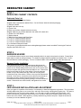
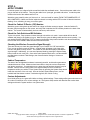
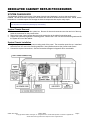
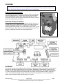
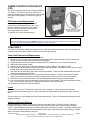
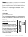
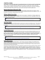
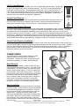
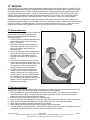

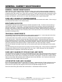


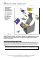
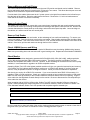

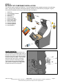
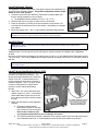
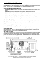
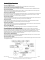
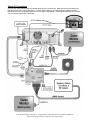


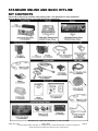


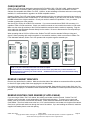

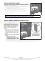

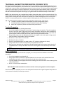
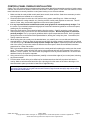

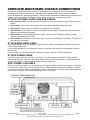
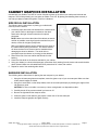


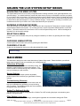

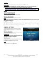

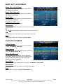
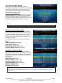
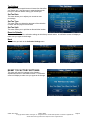
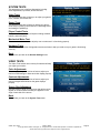
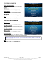

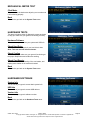
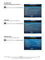


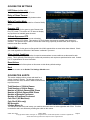
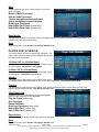
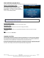

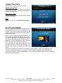


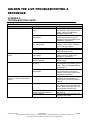
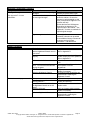
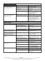
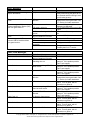
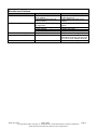

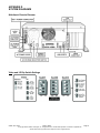
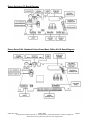

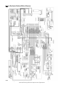

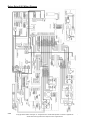


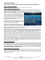
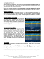
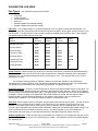

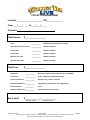


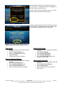

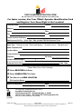

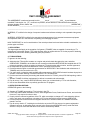
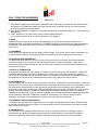
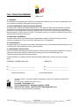

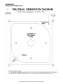


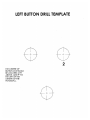

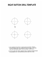

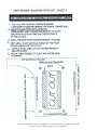
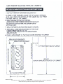

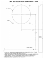


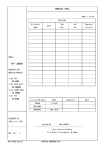


![[SPT-3000] e](http://vs1.manualzilla.com/store/data/005667089_1-a5f3766b3193f6552f250995926a69c5-150x150.png)