1
AX5410P
16 Channels Opto-Isolated
Digital Input Card
with PCI Bus
User’s Manual
Disclaimers
The information in this manual has been carefully checked and is believed to be
accurate. AXIOMTEK Co., Ltd. assumes no responsibility for any infringements of
patents or other rights of third parties which may result from its use.
AXIOMTEK assumes no responsibility for any inaccuracies that may be contained in
this document. AXIOMTEK makes no commitment to update or to keep current the
information contained in this manual.
AXIOMTEK reserves the right to make improvements to this document and/or
product at any time and without notice.
No part of this document may be reproduced, stored in a retrieval system, or
transmitted, in any form or by any means, electronic, mechanical, photocopying,
recording, or otherwise, without the prior written permission of AXIOMTEK Co.,
Ltd.
Copyright 2000 by AXIOMTEK Co., Ltd.
All rights reserved.
April 2000, Version A2
Printed in Taiwan
ii
ESD Precautions
Integrated circuits on computer boards are sensitive to static
electricity. To avoid damaging chips from electrostatic discharge,
observe the following precautions:
Do not remove boards or integrated circuits from their anti-static
packaging until you are ready to install them.
Before handling a board or integrated circuit, touch an unpainted
portion of the system unit chassis for a few seconds. This helps to
discharge any static electricity on your body.
Wear a wrist-grounding strap, available from most electronic
component stores, when handling boards and components.
Trademarks Acknowledgments
AXIOMTEK is a trademark of AXIOMTEK Co., Ltd.
IBM is a registered trademark of International Business
Machines Corporation.
MS-DOS, Microsoft C and QuickBasic are trademarks of
Microsoft Corporation.
TURBO C is a trademark of Borland Inc.
BASIC is a trademark of Dartmouth College.
Intel is a trademark of Intel Corporation.
Other brand names and trademarks are the properties
and registered brands of their respective owners.
iii
Unpacking
The AX5410P is packed in an anti-static bag. The board has
components that are easily damaged by static electricity. Do not
remove the anti-static wrapping until proper precautions have
been taken. Safety instructions in front of this User’s Manual
describe anti-static precautions and procedures.
After unpacking the board, place it on a raised surface and
carefully inspect the board for any damage that might have
occurred during shipment. Ground the board and exercise
extreme care to prevent damage to the board from static
electricity.
Integrated circuits will sometimes come out of their sockets
during shipment. Examine all integrated circuits, particularly the
BIOS, processor and keyboard controller chip to ensure that
they are firmly seated.
After unpacking the AX5410P, check and see if the following
items are included and in good condition. If any of the items is
missing or damaged, notify your dealer immediately.
! AX5410P Board
! CN-D 37P 180D
! Cable HOODS CN-37P
! AS59099 DAC Driver CD
! AX5410P User‘s Manual
! Warranty Card
Make sure that all of the items listed above are present.
What To Do If There Is A Problem
If there are damaged or missing parts, contact your supplier
and/or dealer immediately. Do not attempt to apply power to the
board if there is damage to any of its components.
iv
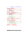
Table
Chapter 1
1.1
1.2
1.3
1.4
1.5
Introduction
Installation
Base I/O Port Address and IRQ Level ............... 5
Connector Pin Assignments ............................. 5
AC or DC Input Select....................................... 6
Jumper Settings ............................................... 7
Signal Wiring .................................................... 8
2.5.1
2.5.2
2.5.3
2.5.4
2.6
Dry Contact (1) .......................................................8
Dry Contact (2) .......................................................8
Voltage Input...........................................................9
TTL Devices (With Isolation) ................................... 10
Hardware Installation ..................................... 11
2.6.1
Board Installation .................................................. 11
Chapter 3
3.1
Register Structure & Format
I/O Address Mapping ...................................... 13
Chapter 4
4.1
Device Driver
Installing the Device Driver ............................ 15
4.1.1
4.2
Contents
General Description.......................................... 1
Features ........................................................... 1
Specifications................................................... 2
Screw Terminal Panel ....................................... 2
Software Package ............................................. 3
Chapter 2
2.1
2.2
2.3
2.4
2.5
of
Using the Device Driver Command ...................... 16
Programming Examples.................................. 17
4.2.1. Sample Program in Turbo C .................................. 17
4.2.2. Sample Program in Turbo Pascal .......................... 18
4.2.3. Sample Program in Qbasic 4.5 ............................. 19
Appendix A
Appendix B
Table of Contents
Block Diagram
Location Diagram
v
This page does not contain any information.
vi
AX5410P 16 Channel Opto-Isolated Digital Input Card User’s Manual
Chapter
1
Introduction
1.1
General Description
The AX5410P provides 16 isolated digital input channels. It
plugs directly into any 32-bit PCI Bus. The 16 opto-isolated D/I
channels are ideal for sensing digital inputs, and provide 1000V
of isolation. Each channel is optically isolated from system
circuit and other input channels. You can configure each input
channel individually by setting the jumpers for either voltage
mode or dry contact mode input operation. The configuration of
a channel in voltage mode may either be DC signal or AC signal
input, depending on the jumper setting. In the past, we usually
perform polling in order to acknowledge status change of input
signal, causing a waste in CPU time. Now, AX5410P offers an
onboard intelligent detector circuit that asserts an interrupt
signal to CPU when change of input signal occurs. For this
reason, the AX5410P supports 16 onboard LEDs that displays
the input channel’s status.
1.2
Features
32-bit PCI Bus compatible D/I card
Plug and play
16 opto-isolated digital inputs
1000V fully isolation
37-pin D-type male connector included
LEDs indicate input status
Intelligent signal change detection to assert interrupt
DC/AC input signal selectable
Voltage/Dry contact mode selectable(Both with isolation)
Windows 95/Windows NT driver and DOS DEMO program
provided
Introduction
1
AX5410P 16 Channel Opto-Isolated Digital Input Card User’s Manual
1.3
Specifications
Isolated Input
!
!
!
!
!
!
!
Indication Display: 16 Red LEDs
Indication Mode:
Logic “1” :LED on
Logic “0” :LED off
Opto-isolator: PC814
Input Channels: 16
Isolation: 1000V channel-to-channel and
channel-to-ground
Throughput: 10KHz max.
Interrupt Throughput: 7KHz max.
Voltage Input Mode
! Input Signal: AC and DC Don’t care polarity
! Input Range: 4 to 24VDC/AC
! Input Impedance: 1.2K/1W
Dry Contact Input Mode
!
!
Internal Detecting Voltage Supply: +5VDC
Input Type: Logic “1” : Close
Logic “0” : Open
Interface Characteristic
! I/O Connector: 37-pin D-type male connector
Power Requirements
! +5VDC: 0.6A max.
Physical/Environmental
! Dimensions: 175x100 mm
! Weight: 155g
! Relative Humidity: 0 to 90%; non-condensing
1.4
Screw Terminal Panel
AX851: DP-37 Universal Screw Terminal Panel
Introduction
2
AX5410P 16 Channel Opto-Isolated Digital Input Card User’s Manual
1.5
Software Package
AS59020: DAC Win 95 Driver
AS59040: DAC Win NT Driver
Introduction
3
AX5410P 16 Channel Opto-Isolated Digital Input Card User’s Manual
This page does not contain any information.
Introduction
4
AX5410P 16 Channel Opto-Isolated Digital Input Card User’s Manual
Chapter
2
Installation
2.1
Base I/O Port Address and IRQ Level
AX5410P occupies eight I/O port spaces. The PCI Plug & Play
BIOS assigns the I/O port base address and IRQ level. From the
device driver, user can get the base address, IRQ level and plus
the slot number where AX5410P is plugged into. For more
detailed information, refer to the Chapter “Device Driver”.
2.2
Connector Pin Assignments
All AX5410P D/I signals are built inside one 37-pin D-type
male connector (CN1). Shown on the following diagram are the
pin assignments of CN1.
SIGNAL
PIN
PIN
SIGNAL
DI 0DI 1DI 2DI 3DI 4DI 5DI 6DI 7DI 8DI 9DI 10DI 11DI 12DI 13DI 14DI 15(*2)
(*3)
20
21
22
23
24
25
26
27
28
29
30
31
32
33
34
35
36
37
1
2
3
4
5
6
7
8
9
10
11
12
13
14
15
16
17
18
19
DI 0+
DI 1+
DI 2+
DI 3+
DI 4+
DI 5+
DI 6+
DI 7+
DI 8+
DI 9+
DI 10+
DI 11+
DI 12+
DI 13+
DI 14+
DI 15+
(*1)
(*3)
(*3)
(*1): +12V / NC SELECTABLE
CN1
(*2): VCC / NC SELECTABLE
(*3): GND / NC SELECTABLE
Installation
5
AX5410P 16 Channel Opto-Isolated Digital Input Card User’s Manual
2.3
Pin
Jumper
ON
OFF
17
J1
+12V
NC
36
J2
VCC
NC
18,19,37
J3
GND
NC
AC or DC Input Select
Both AC and DC signals can be input to AX5410P channels.
Each input channel is equipped with jumper-selectable filter.
The jumpers are JP17 and JP18. For DC input, filter is not
required. For AC input, filter must be configured to the
associated channel. The following table lists jumpers and its
corresponding channels. In factory, filter is configured to each
input channels.
Jumper
Input Channels
JP17
Channels 1 through 8
JP18
Channels 9 through 16
VCC
INTERNAL
CIRCUIT
DI n+
C (AS FILTER)
DI n -
Installation
6
JP17, JP18
AX5410P 16 Channel Opto-Isolated Digital Input Card User’s Manual
2.4
Jumper Settings
AX5410P accepts two kinds of signals as digital inputs: voltage
input and dry contact, both configurable by setting the jumpers
JP1 through JP16 onboard.
Refer to the following diagrams for the corresponding jumper
settings of both signals.
JP1
\
JP16
for voltage input
(Default setting)
V
D
JP1
\
JP16
for dry contact signal
V
D
V: Voltage Input
D: Dry Contact Signal
Installation
7
AX5410P 16 Channel Opto-Isolated Digital Input Card User’s Manual
2.5
Signal Wiring
The AX5410P accepts digital input signals from TTL devices,
dry contacts and voltage inputs. Install jumpers (JP1~JP16) for
dry contacts or voltage inputs according to previous section.
With jumpers installed, the input signal is isolated from the
internal circuit. Described on the following sections are the
signal wirings for each case.
2.5.1 Dry Contact (1)
Connect the dry contacts directly to the digital input (DI+, DI-)
and set jumpers as shown below. Use this connection in high
voltage interference free environment (i.e. indoors, short
distance).
V
D
V
JP1
DI 1 DI 1 +
D
V
JP2
DI 2 DI 2 +
D
JP16
DI 16 DI 16 +
2.5.2 Dry Contact (2)
In some situations, the dry contacts are connected in a distance
from the system. User may use the following connection to
isolate the internal circuit, and to protect the internal circuit
from noise interference.
You must add a voltage source (3V – 24V) between the
NOTE:
dry contact and digital input in order to activate the
opto isolator. Jumpers are set for voltage input.
Installation
8
AX5410P 16 Channel Opto-Isolated Digital Input Card User’s Manual
V
D
V
JP1
D
V
JP2
DI 1+
DI 1-
D
JP16
DI 2+ DI 2-
DI 16+
DI 16-
VOLTAGE
SOURCE
REMOTE
SWITCH
2.5.3 Voltage Input
Set jumpers and place a voltage source (3V-24V) according to
the description below. The voltage input signals are isolated
from the internal circuit.
V
D
JP1
V
D
JP2
DI 1+
Installation
DI 1-
V
D
DI 16+
DI 16-
JP16
DI 2+
DI 2-
9
AX5410P 16 Channel Opto-Isolated Digital Input Card User’s Manual
2.5.4 TTL Devices (With Isolation)
Simply connect the output points of TTL devices to AX5410P.
The figures below give a brief description of the connections
and jumpers settings.
DATA
STATUS
1
ON
OFF
0
V
D
JP1
V
D
V
JP2
DI 1+
DI 1-
JP16
DI 2+
DATA
DI 2-
D
JP1
DATA
STATUS
1
OFF
ON
V
DI 1-
DI 16-
DATA
D
JP2
DI 1+
DI 16+
DATA
0
V
D
V
D
JP16
DI 2+
DI 2-
DI 16+
DI 16-
VCC
DATA
Installation
10
DATA
DATA
AX5410P 16 Channel Opto-Isolated Digital Input Card User’s Manual
2.6
Hardware Installation
The AX5410P board is shipped with protective electrostatic
cover. When unpacking, touch the board’s electrostatically
shielded packaging with the metal frame of your computer to
discharge the accumulated static electricity prior to touching the
board.
The following summarizes the installation procedures of
AX5410P:
WARNING:
TURN OFF the PC and all accessories connected to
the PC whenever installing or removing any
peripheral board including the AX5410P board.
2.6.1 Board Installation
Turn off the PC and all accessories power.
Unplug all power cords and entire cables from the rear
of the PC.
Remove the PC’s cover (see your PC operation Guide if
you are not skillful about it).
Find an unused expansion slot. Remove the blank
expansion slot cover and save the screw for affixing
retaining bracket.
Grab the upper edge of the AX5410P board. Align the
AX5410P board’s retaining bracket with the expansion
slot rear panel, and straighten the board’s gold finger
with the expansion slot, crush the board into the slot.
Restore the screw to the expansion slot retaining
bracket.
Replace the PC’s cover and connect the cables you
detached in step 2.
Turn on the PC and other peripheral devices power, go
on the next chapter for software installation
procedures.
Installation
11
AX5410P 16 Channel Opto-Isolated Digital Input Card User’s Manual
This page does not contain any information.
12
AX5410P 16 Channel Opto-Isolated Digital Input Card User’s Manual
Chapter
3
Register Structure & Format
3.1
I/O Address Mapping
This chapter describes the register format and function. The
AX5410P use only one I/O address. The register is 16 bits wide
and show below.
Location
Function
Base Address
Type
Channels 1 through 16
Read
Base Address
MSB
D16
D15
D14
D13
D12
D11
D10
D9
D8
D7
D6
D5
D4
D3
D2
D1
LSB
D1-D16 represent digital input status for channels 1 through 16.
AX5410P registers can be accessed easily through direct I/O
instructions, using whatever application language available (i.e.,
Assembly, Basic, Pascal, C, etc.).
Enable interrupt
AX5410P offers an onboard intelligent detector circuit that
asserts an interrupt signal to CPU when a change of input signal
occurs.
Enable : write “1” to base address, outport(base+0,0x01);
After generating an interrupt, a read action at base address in
user’s ISR (interrupt service routine) program is necessary to
release the interrupt line, enabling others to interrupt.
Disable: write “0” to base address, outport(base+0,0x00);
Register Structure & Format
13
AX5410P 16 Channel Opto-Isolated Digital Input Card User’s Manual
This page does not contain any information.
14
AX5410P 16 Channel Opto-Isolated Digital Input Card User’s Manual
Chapter
4
Device Driver
The AX5410P device driver is suitable for Plug & Play under
DOS environment when generating information from PCI BIOS.
This chapter describes in detail on how to install the device
driver and use the device driver command to get base address,
IRQ level, slot number. Testing programs are also provided for
reference.
After successfully retrieving the information, user can use the
information to act as parameter for driver function. All
operations within this section will only work if the device driver
“AX5410P.SYS” is successfully installed. There are testing
programs provided in this chapter for reference purposes only.
4.1
Installing the Device Driver
Before executing any application program (including the
following examples), this device driver must be installed. To
install the device driver, type
SETUP [SOURCE DRIVE] [TARGET DRIVE] [DIRECTORY]
This will copy the device driver to the desired directory. After
completion, add the following command line to your config.sys:
DEVICE = [PATH] AX5410P.SYS
Example
If you insert this diskette in drive A: and want to copy the file
into C:\AX5410P. You must key in the following command line
at the DOS prompt.
A:\SETUP
A:
C:
AX5410P
[ENTER]
Then add the following line to your config.sys file.
DEVICE = C:\AX5410P\AX5410P.SYS
Reboot your computer.
Device Driver
15
AX5410P 16 Channel Opto-Isolated Digital Input Card User’s Manual
If the AX5410P is plugged in your system, the following
message appears:
******************************* *
*
Copyright 1998 by AXIOMTEK Co., LTD
*
*
Ver 1.0
*
*
AX5410P DEVICE DRIVER INSTALLED
*
******************************* *
Now AX5410P acts like a file. You can OPEN, CLOSE,
WRITE (command), READ (base address, IRQ level, slot
number) it via this device driver. If there is no AX5410P in your
system, the following message appears:
AX5410P
or
PCI BIOS Not Found !!
Any attempt to OPEN the device driver will fail !
4.1.1
Using the Device Driver Command
The device driver is for the user to retrieve Base Address, IRQ
Level, and Slot Number of AX5410P plugged in your system.
Before accessing the device driver, open it as needed. After
accessing the device driver, close it as also needed. To get any
information (Base Address, IRQ Level or Slot Number), you
must first write a command to the device driver in order for the
needed data to be read from the device driver.
There are three commands for user to obtain Base Address, IRQ
level and Slot Number. To get base address, you must write the
command string "B?" to the device driver and then read a
WORD (two bytes) from the device driver. This is the base
address you need.
To get the IRQ level, you must write the command string "I?" to
the device driver and then read a WORD (two bytes) from the
device driver. This is the IRQ level you need.
To acquire the slot number, you must write the command string
"S?" to the device driver and then read a WORD (two bytes)
from the device driver. This is the slot number you need.
Device Driver
16
AX5410P 16 Channel Opto-Isolated Digital Input Card User’s Manual
NOTE:
4.2
The question mark “?” must be replaced by a card
number. If Base Address returns to 0, it means all
information retrieved by the card number are not
available.
Programming Examples
4.2.1.
Sample Program in Turbo C
** * * * * * * * * * * * * * * * * * * * * * * * * *
* Example program for Turbo C language
* To get BASE ADDRESS
*
SLOT NUMBER via device driver
* Before executing this program, device
* driver must be installed successfully.
** * * * * * * * * * * * * * * * * * * * * * * * * *
#include
#include
#include
#include
#include
#include
<dos.h>
<stdio.h>
<string.h>
<conio.h>
<fcntl.h>
<io.h>
main()
{
int
int
fd;
base, busno
*
*
*
*
*
*
*
if ((fd=open("5410drv",O_RDWR))= = -1 ) {
printf("AX5410P OPEN FAIL !\n");
exit(0);
}
else
printf("OK\n");
write(fd,"B1",2);
read(fd, &base,sizeof(int));
write(fd,"S1",2);
read(fd,&busno,sizeof(int));
Device Driver
17
AX5410P 16 Channel Opto-Isolated Digital Input Card User’s Manual
close(fd);
clrscr();
printf("BASE ADDRESS :%x\n",base);
printf("SLOT NUMBER :%x\n", busno);
if (base = = 0) {
printf("ERROR INFORMATION !\n");
exit(0);
}
}
4.2.2.
*
*
*
*
*
*
*
Sample Program in Turbo Pascal
*******************************
Example program for Turbo PASCAL language
To get BASE ADDRESS
SLOT NUMBER via device driver
Before executing this program, device driver must
be installed successfully.
*******************************
PROGRAM AX5410P(input);
uses dos,crt;
var
fdw:text;
fdr :file of integer;
addr,slotno:intrger;
begin
clrscr;
assign(fdw,'5410drv');
assign(fdr,'5410drv');
rewrite(fdw);
writeln(fdw,'b1');
reset(fdr);
read(fdr,addr);
rewrite(fdw);
writeln(fdw,'s1');
reset(fdr);
read(fdr,slotno);
Device Driver
18
*
*
*
*
*
*
*
AX5410P 16 Channel Opto-Isolated Digital Input Card User’s Manual
close(fdw);
close(fdr );
writeln('BASE ADDRESS : ',addr:10);
writeln('SLOT NUMBER :',slotno:10);
if addr <> 0 then writeln('The information are correct');
END.
4.2.3.
*
*
*
*
*
*
*
Sample Program in QBasic 4.5
*****************************
Example program for QB45 language
To get BASE ADDRESS
SLOT NUMBER via device driver
Before executing this program, device driver must
be installed successfully.
*****************************
*
*
*
*
*
*
*
OPEN "5410drv" FOR OUTPUT AS #1
OPEN "5410drv" FOR BINARY AS #2
PRINT #1, "B1"
GET #2, 1, BL%
GET #2, 1, BH%
PRINT #1, "S1"
GET #2, , S%
CLOSE #1
CLOSE #2
BL = BL%
BH = BH%
ADDR = BH * 256 + BL
PRINT "BASE ADDRESS: ", ADDR
PRINT "SLOT NUMBER : ",S%
IF ADDR <> 0 THEN PRINT " The information are correct"
Device Driver
19
AX5410P 16 Channel Opto-Isolated Digital Input Card User’s Manual
This page does not contain any information.
20
AX5410P 16 Channel Opto-Isolated Digital Input Card User’s Manual
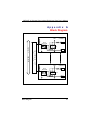
Appendix
A
Block Diagram
vcc
VISO
DI 1+
OPTO
ISOLATOR
2
1
P
C
I
B
U
S
I
N
T
E
R
N
A
L
C
I
R
C
U
I
T
CHANNEL1
4
3
6
5 JP1
DI 1-
vcc
VISO
CHANNEL16
DI 16+
OPTO
ISOLATOR
2
1
4
3
6
JP16
5
DI 16-
Block Diagram
21
AX5410P 16 Channel Opto-Isolated Digital Input Card User’s Manual
This page does not contain any information.
22
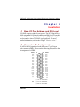
ISO1
ISO2
ISO3
ISO4
ISO5
ISO6
ISO7
ISO8
IS09
ISO10
ISO11
ISO12
ISO13
ISO14
ISO15
ISO16
JP1
JP2
JP3
JP4
JP5
JP6
JP7
JP8
JP9
JP10
JP11
JP12
JP13
JP14
Location Diagram
JP15
JP16
RP10
JP18
JP17
RP5
RP9
D2
D3
D4
D5
D6
D7
D8
D9 D10 D11 D12 D13 D14 D15 D16
D1
AX5410P 16 Channel Opto-Isolated Digital Input Card User’s Manual
Appendix
B
Location Diagram
23
AX5410P 16 Channel Opto-Isolated Digital Input Card User’s Manual
This page does not contain any information.
24