1
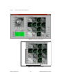
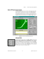
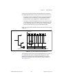
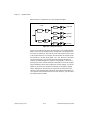
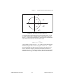
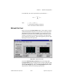
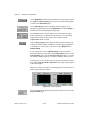
Contents
Figure 3-4.
Figure 3-5.
Figure 3-6.
Figure 3-7.
Figure 3-8.
Figure 3-9.
Pseudo Wigner–Ville Distribution with Gaussian Window w[m]
for the Three-Tone Test Signal ............................................................. 3-7
Pseudo Wigner–Ville Distribution for the Three-Tone Test Signal ..... 3-8
Choi–Williams Distribution (a = 1) for the Three-Tone Test Signal.... 3-9
Cone-Shaped Distribution (a = 1) for the Three-Tone Test Signal ...... 3-10
Gabor Spectrogram (Order Four) for the Three-Tone Test Signal ....... 3-12
Adaptive Spectrogram for the Three-Tone Test Signal ........................ 3-13
Figure 5-1.
Figure 5-2.
Figure 5-3.
Figure 5-4.
Figure 5-5.
Figure 5-6.
Figure 5-7.
Gabor Expansion-Based Denoise ......................................................... 5-3
2D STFT for Image Analysis................................................................ 5-4
Subimage Frequency Contents ............................................................. 5-4
2D STFT for the Image Analysis in Figure 5-2 .................................... 5-6
Online STFT Spectrogram Analyzer Panel .......................................... 5-7
Offline Joint Time-Frequency Analyzer ............................................... 5-9
Instantaneous Spectrum Display .......................................................... 5-11
Figure 6-1.
Figure 6-2.
STFT Spectrogram (Hanning Window)................................................ 6-4
Gabor Spectrogram (Order Four).......................................................... 6-5
Figure 9-1.
Figure 9-2.
Figure 9-3.
Figure 9-4.
Figure 9-5.
Figure 9-6.
Figure 9-7.
Figure 9-8.
Figure 9-9.
Figure 9-10.
Sum of Two Truncated Sine Waveforms.............................................. 9-2
Wavelet ................................................................................................. 9-4
Wavelet Analysis .................................................................................. 9-6
Short-Time Fourier Transform Sampling Grid..................................... 9-7
Wavelet Transform Sampling Grid....................................................... 9-8
Comparison of Transform Processes .................................................... 9-9
Detection of Discontinuity .................................................................... 9-10
Multiscale Analysis............................................................................... 9-11
Detrend.................................................................................................. 9-12
Denoise ................................................................................................. 9-13
Figure 10-1.
Figure 10-2.
Two-Channel Filter Bank ..................................................................... 10-1
Relationship of Two-Channel PR Filter Banks
and Wavelet Transform......................................................................... 10-2
Figure 10-3. Filter Bank and Wavelet Transform Coefficients ................................. 10-3
Figure 10-4. Halfband Filter ...................................................................................... 10-6
Figure 10-5. Zeros Distribution for (1 – z –1)6Q(z).................................................... 10-7
Figure 10-6. B-Spline Filter Bank ............................................................................. 10-7
Figure 10-7. Dual B-Spline Filter Bank .................................................................... 10-8
Figure 10-8. Third-Order Daubechies Filter Banks and Wavelets ............................ 10-11
Figure 10-9. 2D Signal Processing ............................................................................ 10-12
Figure 10-10. 2D Image Decomposition ..................................................................... 10-13
Signal Processing Toolset
xiv
© National Instruments Corporation