1
CRC
Technical Reference Manual
P/N 3100132 • Rev 1.0 • 01NOV01
Technical Manuals Online! - http://www.tech-man.com
DEVELOPED BY
Edwards Systems Technology
6411 Parkland Drive
Sarasota, FL 34243
(941) 739-4300
COPYRIGHT NOTICE
Copyright © 2001 Edwards Systems Technology, Inc.
This manual and the products it describes are copyrighted by
Edwards Systems Technology, Inc. (EST). You may not
reproduce, translate, transcribe, or transmit any part of this
manual without express, written permission from EST.
This manual contains proprietary information intended for
distribution to authorized persons or companies for the sole
purpose of conducting business with EST. If you distribute any
information contained in this manual to unauthorized persons,
you have violated all distributor agreements and we may take
legal action.
CREDITS
This manual was designed and written by the EST Technical
Services - Documentation Department, Sarasota.
DOCUMENT HISTORY
Date
Revision
Reason for change
01NOV01
1.0
Initial publication.
Technical Manuals Online! - http://www.tech-man.com
Content
Chapter 1
Introduction • 1.1
About this manual • 1.2
Introduction to the CRC • 1.3
Physical description • 1.4
Overview of operation • 1.5
Chapter 2
Features and functions • 2.1
CRC features • 2.2
CRC functions • 2.8
Mounting • 2.11
Supervision • 2.12
Chapter 3
Hardware and equipment • 3.1
Basic equipment • 3.2
Control panel modules • 3.3
SAC bus and wiring • 3.4
CRC connections and options • 3.5
Card readers and access cards • 3.9
Software packages • 3.11
Chapter 4
Access control applications • 4.1
Other factors • 4.2
Anti-passback • 4.4
Central monitoring station • 4.7
Common door access • 4.9
Delayed egress • 4.11
Elevator control • 4.14
Emergency exit door • 4.17
Handicap access door • 4.19
Maglock peripherals • 4.21
Multiple card readers • 4.23
Muster • 4.25
Power for continuous locks • 4.28
Power for intermittent locks • 4.30
Power from an ac source • 4.32
Power from a remote source • 4.35
Remote controls • 4.38
Two-person rule • 4.40
Chapter 5
Installation • 5.1
Installation guidelines • 5.2
Wiring the CRC • 5.5
Installing and wiring the card reader • 5.8
Installing the door locks • 5.9
Checking operation with a construction card • 5.12
NFPA 72 • 5.13
CRC Technical Reference Manual
Technical Manuals Online! - http://www.tech-man.com
i
Content
Chapter 6
Programming • 6.1
SDU • 6.2
ACDB • 6.10
Chapter 7
Operation • 7.1
CRC processing • 7.2
Sounder Output • 7.7
Card reader LED outputs • 7.8
Card reader power • 7.10
Lock power • 7.11
Chapter 8
Maintenance and troubleshooting • 8.1
Maintenance • 8.2
CRC troubleshooting • 8.3
Card reader troubleshooting • 8.4
Access control cards troubleshooting • 8.6
Y
Glossary • Y.1
Z
Index • Z.1
ii
Technical Manuals Online! - http://www.tech-man.com
CRC Technical Reference Manual
Content
Important information
Limitation of liability
The content of this manual is proprietary in nature and is
intended solely for distribution to authorized persons,
companies, distributors and/or others for the sole purpose of
conducting business associated with EST. The distribution of
information contained within this manual to unauthorized
persons shall constitute a violation of any distributor agreements
and may result in implementation of legal proceedings.
Installation in accordance with this manual, applicable codes,
and the instructions of the Authority Having Jurisdiction is
mandatory. EST shall not under any circumstances be liable for
any incidental or consequential damages arising from loss of
property or other damages or losses owing to the failure of EST
products beyond the cost of repair or replacement of any
defective products. EST reserves the right to make product
improvements and change product specifications at any time.
While every precaution has been taken during the preparation of
this manual to ensure the accuracy of its contents, EST assumes
no responsibility for errors or omissions.
FCC warning
This equipment can generate and radiate radio frequency energy.
If this equipment is not installed in accordance with this manual,
it may cause interference to radio communications. This
equipment has been tested and found to comply within the limits
for Class A computing devices pursuant to Subpart B of Part 15
of the FCC Rules. These rules are designed to provide
reasonable protection against such interference when this
equipment is operated in a commercial environment. Operation
of this equipment is likely to cause interference, in which case
the user at his own expense, is required to take whatever
measures may be required to correct the interference.
CRC Technical Reference Manual
Technical Manuals Online! - http://www.tech-man.com
iii
Content
Approvals
The Card Reader Controller (CRC) has been submitted to the
following approval agencies for listing:
•
•
•
Federal Communications Commission (FCC)
Underwriters Laboratories Inc. (UL)
Underwriters Laboratories of Canada (ULC)
The CRC is compatible with the EST3 System.
iv
Technical Manuals Online! - http://www.tech-man.com
CRC Technical Reference Manual
Chapter 1
Introduction
Summary
This chapter introduces you to the Card Reader Controller
(CRC). We describe the CRC and present an overview of its
operation.
Content
About this manual • 1.2
Introduction to the CRC • 1.3
Physical description • 1.4
Overview of operation • 1.5
CRC Technical Reference Manual
Technical Manuals Online! - http://www.tech-man.com
1.1
Introduction
About this manual
Purpose of the manual
This manual shows you how to design and develop an access
control system based on the capabilities of the Card Reader
Controller (CRC). It also provides information on how to install,
wire, configure, and maintain the CRC and related components.
Intended audience
This manual and the information it contains are intended for
people who have experience with fire alarm systems, and a basic
knowledge of security and access control applications.
Organization
This manual is organized into chapters. Here are brief
descriptions of the chapters.
Chapter 1: Introduction. Provides information on how this
manual is structured and gives a basic overview of the CRC.
Chapter 2: Features and functions. Provides a detailed look at
the CRC’s primary features and functions.
Chapter 3: Hardware and equipment. Provides a detailed list of
compatible equipment that can be used with a CRC and an
access control system.
Chapter 4: Access control applications. Provides information on
designing an access control system using the CRC and related
components.
Chapter 5: Installation. Provides details on how to install a CRC
and associated devices.
Chapter 6: Programming. Breaks configuration down into SDU
and ACDB options. This chapter gives a definition and
explanation of each configuration option or setting.
Chapter 7: Operation. This chapter explains the operations of
the CRC and some of its related components.
Chapter 8: Maintenance and troubleshooting. Explains different
problems that may arise while using the CRC, card readers, or
access control system and gives suggested solutions.
The manual includes a glossary and an index.
Related documents
ACDB User Manual (P/N 270961)
CRC CRCXM Card Reader Controller (P/N 387625)
1.2
Technical Manuals Online! - http://www.tech-man.com
CRC Technical Reference Manual
Introduction
Introduction to the CRC
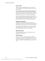
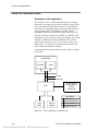
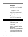
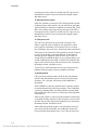
The Card Reader Controller (CRC) is shown in Figure 1-1. The
CRC interfaces card readers and door locks to an integrated
system (fire, security, and access control) allowing access to a
protected area only when a cardholder presents a valid access
card, and has access privileges for that area. The intelligence for
controlling access is programmed into the CRC.
Figure 1-1: Card Reader Controller
CRCs are connected by a dedicated RS-485 circuit, called a
SAC bus. The SAC bus allows the CRC to communicate with a
control panel. The control panel can support an integrated
security, access control, and fire alarm system.
Model CRCXM is a version of the CRC with expanded memory
capacity. It has the same physical and functional attributes as the
CRC, but can store a larger database of cardholder and history
records.
For specifications please refer to the installation sheet CRC
CRCXM Card Reader Controller, P/N 387625.
CRC Technical Reference Manual
Technical Manuals Online! - http://www.tech-man.com
1.3
Introduction
Physical description
The CRC has a streamlined white housing, designed to blend in
with most surroundings. This lets you install the CRC in plain
sight, which typically requires much less time and effort.
The CRC has terminals for connection to the SAC bus, power,
card reading devices, and door locking mechanism. Space is
provided for a standby battery. The CRC battery continues to
operate the CRC in case of a power failure. Jumpers are
provided for configuring the CRC to use ac or dc power, and to
operate continuous or intermittent operation door locks.
1.4
Technical Manuals Online! - http://www.tech-man.com
CRC Technical Reference Manual
Introduction
Overview of operation
Each door being used for access control requires a CRC, a card
reading device, and an electric door lock. Both the card reader
and door lock are wired to the CRC.
An access card is assigned to each person that requires access.
The access card is equipped with a unique code that must be
entered into the database of the CRC. The unique code allows
the CRC to recognize a valid cardholder.
Each cardholder is assigned a set of access privileges that
determine the times and conditions under which access is
granted. The set of privileges is called an access level
When a card is read at the card reader, the following sequence of
events occurs before the person is granted access:
1. The reader interprets the code on the card and forwards this
data to the CRC.
2. The CRC determines whether to grant access. Some of the
questions that must be satisfied to make this decision are:
•
Does the card code exist in the CRC database?
•
Does the cardholder have disarm privileges for the
security partition assigned to the CRC?
•
Is the security partition armed in the area being
accessed?
•
Is the time of day within the access level schedule?
•
Does the person have an irregular access privilege?
3. If the CRC determines that the person has the correct access
privileges, it releases the door lock, thereby allowing the
person to open the door.
4. The CRC automatically shares entry and exit event
information when there are multiple CRCs within a
partition.
5. Entry and exit event information required by external
integrated gateway connections (such as FireWorks) is
automatically sent to the control panel.
CRC Technical Reference Manual
Technical Manuals Online! - http://www.tech-man.com
1.5
Introduction
1.6
Technical Manuals Online! - http://www.tech-man.com
CRC Technical Reference Manual
Chapter 2
Features and functions
Summary
This chapter provides detailed definitions of the CRC’s features
and functions.
Content
CRC features • 2.2
System integration • 2.2
Enhanced survivability • 2.2
System CRC capacity • 2.2
Controls for readers and locks • 2.3
LED and CRC sounder drivers • 2.3
CRC dry contact relay connections • 2.3
CRC input circuits • 2.4
Access cards • 2.4
Card readers • 2.4
Database storage • 2.4
Access levels and schedules • 2.5
Schedules and holidays • 2.5
Database capacities • 2.6
User-defined logged attempts • 2.6
User-defined PIN schedule • 2.6
User-defined unlock and open times • 2.7
CRC functions • 2.8
Construction mode • 2.8
Security partition disarming • 2.8
Alarm point bypass • 2.8
Cardholder disability • 2.8
Multiple tenants • 2.9
Elevator floor access control • 2.9
Visitor and escort function • 2.9
Anti-passback options • 2.9
Muster function • 2.9
Two-person rule • 2.10
Mounting • 2.11
Physical design • 2.11
Distance from panel • 2.11
Supervision • 2.12
CRC ac power • 2.12
CRC cover • 2.12
CRC low battery • 2.12
CRC to card reader connection • 2.12
CRC to lock connection • 2.12
CRC Technical Reference Manual
Technical Manuals Online! - http://www.tech-man.com
2.1
Features and functions
CRC features
System integration
The CRC integrates seamlessly with the EST3 fire alarm system.
If a fire alarm occurs, a simple program rule can unlock exit
doors. With fire and security devices installed on the same
network, no degradation in system performance occurs.
Because each CRC makes its own access decisions, very little
network traffic is generated by the access control function. This,
along with the integrated design of the network operating
system, ensures that fire signals always receive the highest
priority. To reduce traffic even further, the SDU optimizes
which event messages the system receives.
Enhanced survivability
In performing its task, the CRC maintains a database of up to
8,000 users with all options and schedules. It also stores the
5,000 most recent access denied (and optionally, access granted)
events.
The CRCXM stores up to 36,000 users and 20,000 events.
If the control panel 3-CPU1 or 3-SAC fails, or if the CRC loses
communication with the 3-SAC, the CRC continues to function
without any degradation.
If power is lost to the CRC, it can continue to operate on its own
internal battery power. The CRC will continue to grant and deny
access for a limited amount of time (refer to battery calculations
in Appendix A), thereby eliminating the need for granting free
access during a degraded period.
When battery power is exhausted the control panel generates a
communication fault event message for the CRC.
System CRC capacity
In an integrated system, security and access control devices are
connected by a dedicated RS-485 circuit, called a SAC bus. The
SAC bus originates at the Security Access Control module
(3-SAC).
Each 3-SAC can support up to 62 CRC or KPDISP (Keypad
Display) devices for Class B wiring (30 CRCs or KPDISPs for
Class A). This is a multiple-drop circuit and does not require a
dedicated run for each device.
2.2
Technical Manuals Online! - http://www.tech-man.com
CRC Technical Reference Manual
Features and functions
Should network communication be lost, the CRC will continue
to grant access based on the database stored in its memory,
without loss of any security feature.
(Applications that rely on communication between CRCs are the
exception. For example, anti-passback and two-person rule
applications, requiring more than one door, may not work in
degraded mode.)
Controls for readers and locks
Each CRC provides the power and electronics required to
control and monitor a single door. The CRC can accommodate
two card readers (entry and exit) plus an associated electric door
lock. The CRC can use an external 24 Vdc power supply or a
CRCXF CRC Transformer (a 16.5 Vac transformer) to power
continuous-duty locks.
If desired, all entry and exit events can be reported to the
FireWorks Guard Workstation. It is also possible to determine
the current location of an individual and obtain a list of all
people who are in the premises.
The CRC can monitor the door contact and activate an optional
sounder if the door is opened without first badging out. This can
act as a reminder to badge out, and ensure that management
knows who is in the building. It can also act as a simple form of
exit control in the event of an unauthorized exit.
LED and CRC sounder drivers
The CRC provides LED driver terminals for the card readers.
Thus, the readers can visually indicate whether access is granted
or denied.
The CRC provides different LED flash rates for applications that
require a PIN number or a second card. Examples: two-person
rule or escorted visitor.
A driver for an audible sounder is also provided by the CRC.
Refer to the installation sheet for the CRCSND CRC Sounder,
P/N 3100033 for additional information.
CRC dry contact relay connections
The CRC includes common, N.O., and N.C. outputs from a
Form C relay. These can be used to control auxiliary fire alarm
devices such as fans and dampers, as well as devices that
support handicap functions
CRC Technical Reference Manual
Technical Manuals Online! - http://www.tech-man.com
2.3
Features and functions
CRC input circuits
Each CRC has two input circuits for use with access control and
security devices. These are typically used for a door position
sensor and a request to exit device. The input circuits can be
configured for use with a switch, controlled by a receptionist,
that manually unlocks the door. Finally, the input circuits can be
used as security input points.
Access cards
The CRC is compatible with a large variety of access cards.
These cards do not require a specially-ordered facility code. EST
offers access cards that are prenumbered and ready for use. The
EST cards have nonrepeating, unique numbers. This makes it
easy for administrators to add new cards to the access control
system.
When a site has an existing access control system, the CRC is
flexible enough to integrate with most cards and card readers
already in use. To determine which cards and card readers are
compatible with the CRC see Chapter 3, Hardware and
Equipment.
Card readers
The CRC is compatible with a variety of card readers that
communicate using the Security Industry Association (SIA)
Wiegand output format. These include:
•
•
•
•
•
Proximity
Wiegand pin
Magnetic stripe
Smart card
Keypad
To determine which cards and card readers are compatible with
the CRC, see the CRC installation sheet.
Database storage
Each CRC stores a complete database within its memory. It
retains all the data necessary for complete operation of the
devices it controls. This distribution of intelligence maximizes
the speed at which access decisions are made and provides
survivability in the event that the CRC is disconnected from the
network.
Cardholder data is created and maintained by the Access Control
Database (ACDB) program, which runs on the end user’s PC.
2.4
Technical Manuals Online! - http://www.tech-man.com
CRC Technical Reference Manual
Features and functions
This information is encrypted and sent to the CRCs, via either
direct connection or modem (dial-up) connection.
With modem connection, the ACDB program can dial up the
system and send the encrypted database information to
individual CRCs. This allows a single access control database to
serve multiple sites.
Modem connection also permits multiple tenants to share a
common access control system without sharing a common
database.
Access levels and schedules
An access level is a predefined collection of access and security
privileges. One or more cardholders can be assigned the same
access level, and thus would have the same set of privileges.
Access levels consist of a list of doors, each with a specified
schedule. Any combination of doors and schedules can be
assigned to an access level. The access level determines whether
or not a cardholder can access a given door at a given time.
Each cardholder can be assigned two access levels. This helps
the administrator quickly assign multiple access rights to a
single person. For example, a female manger could be assigned
two access levels, one access level for mangers and one access
level for females. This grants the employee access privileges for
the manger-level doors and for all women’s restrooms.
Each access level can have an active date and an expiration date.
This means the two access levels can be used to control rotating
shifts, parking lots, or temporary schedules.
When used for rotating time shifts, the first access level is the
current schedule and the second access level the future schedule.
The first expire date and the second active date reflect the date
of the change of shift.
In parking lots, dual access levels allows for canceling parking
privileges without canceling building access.
In temporary schedule use, the second schedule overrides the
first schedule when active and returns control to the first
schedule when it expires.
Schedules and holidays
The CRC stores the schedules and holidays created in the ACDB
program. Each schedule identifies specific times (in 15-minute
increments) and days when access is granted.
CRC Technical Reference Manual
Technical Manuals Online! - http://www.tech-man.com
2.5
Features and functions
Holidays are exceptions to normal Monday through Sunday
schedules, when different access requirements are desired. Many
holidays can be programmed using rules rather than fixed dates.
This minimizes year-to-year programming required to update
holidays.
For example, schedules for fixed holidays such as January 1,
which can fall on a Saturday or Sunday, are assigned to take
place on the previous Friday or next Monday respectively.
Database capacities
All access decisions are made locally in the CRC. The CRC’s
non-volatile memory holds the cardholder, schedule, and holiday
information required.
A total of 8,000 cardholders can be stored in each CRC. The
CRCXM has additional memory, and supports 36,000
cardholders.
The CRC or CRCXM can store 1,200 access levels (255 per
company). Each cardholder can be assigned two access levels.
The CRC or CRCXM can store 1,200 schedules (255 per
company) and 1,200 holidays (255 per company).
The CRC stores up to 5,000 events per door, ensuring no loss of
history. The CRCXM has additional memory and stores up to
20,000 events. This history information can be uploaded to the
ACDB program on demand, for use in a variety of reports.
User-defined logged attempts
By using a suppression schedule in the ACDB, you can
determine when normal access events are to be logged. Logged
events always include irregular events and unsuccessful
attempts. Determining what you want to be logged helps
eliminate unnecessary events from entering the history buffer.
User-defined PIN schedule
A schedule can be used to define when a PIN must be entered to
verify each card swipe. To use this option, a combination card
reader and keypad must be installed. The use of a PIN decreases
the possibility that a recently lost or stolen card can be used to
gain entry. A schedule defines when a PIN must be used. This
can be during business hours, outside business hours, or at all
times.
The card is always presented first. If the schedule determines
that a PIN is required, the red LED on the card reader will flash
2.6
Technical Manuals Online! - http://www.tech-man.com
CRC Technical Reference Manual
Features and functions
at 1 Hz. This is an indication that the user must enter a PIN. The
user then enters the PIN to gain access.
This option is selectable per door. If no schedule is defined for a
door, that door will not require a PIN. For this application the
keypad used must provide output in standard Dorado 8-bit
Wiegand data format.
User-defined unlock and open times
Using the ACDB program, the administrator can control how
much time a person has to enter or exit through a door. The CRC
controls both the unlock time and door open time, and these can
be set in the ACDB program.
Unlock timers control the number of seconds that the door stays
unlocked when a user badges in. When the unlock timer expires
the door lock locks. The ACDB has three unlock timers:
•
•
•
Standard unlock
Handicap unlock
Manual unlock
The CRC relay can be used to control a door opener. Door open
timers control the number of seconds that the relay stays active.
The ACDB has two door open timers:
•
•
Manual open time
Relay open time
Refer to Chapter 6: Programming for more information on these
fields.
CRC Technical Reference Manual
Technical Manuals Online! - http://www.tech-man.com
2.7
Features and functions
CRC functions
Construction mode
The CRC can operate in a construction mode. In this mode, the
building contractors use specially coded cards for gaining access
before the system is fully operational.
This mode is in effect before the CRC is programmed by the
ACDB. As soon as a card record is downloaded into the CRC,
the construction card stops working.
Remember that temporary cards can be included in the access
control database and downloaded into the CRC. This allows
workmen to continue installation and testing, even after the
ACDB database has been downloaded. The ACDB user can
define an automatic deactivation date for such cards.
The ACDB cannot be used to restore a CRC to its original
condition. This can only be done with the SDU, using the
Remove from 3-SAC download action (found in the
Communication Functions dialog box).
Security partition disarming
A partition is an area of an alarm system that can operate and be
controlled independently. A CRC can be used to disarm one of
255 security partitions.
Alarm point bypass
CRCs can be programmed to automatically bypass alarm points
when a cardholder is granted access. For example, an employee
entrance door may need to be armed at all times. Bypassing this
door contact allows free entry and exit as authorized employees
come and go. If an unauthorized entry is made an annunciation
alarm sounds.
Cardholder disability
A special disability option allows an individual additional access
time. A disability option can be selected for any cardholder.
When such a cardholder presents his card to the reader, the CRC
recognizes the option and provides additional, user-defined
access time and operates a relay that can activate an automatic
door opener.
2.8
Technical Manuals Online! - http://www.tech-man.com
CRC Technical Reference Manual
Features and functions
Multiple tenants
Multiple tenants are supported by the CRC. During system
installation, the available schedules and holidays are allocated to
the tenants, up to 255 per tenant.
Tenants can then control their own access control database,
using a dial-up modem connection or direct RS-232 connection.
Elevator floor access control
Elevator floor access control is possible if you use CRCs in an
integrated system. Because the fire portion of the system is
already interconnected with the elevator controller for elevator
capture functions, floor access control is a simple extension of
an existing function.
Visitor and escort function
The CRC can be used to allow a visitor to gain access only when
with an escort. Both the escort and visitor must badge in at a
card reader to gain access. First the visitor badges in, followed
by the escort. The CRC will only allow access after the escort
has badged in.
Anti-passback options
Anti-passback is a feature of the access control system that
prevents successive use of one card to pass through a controlled
door (in the same direction). The CRC supports three different
versions of anti–passback: strict, timed, and logged.
Muster function
In the event of an evacuation of a building, the muster
application can be used to verify that everyone has exited the
building.
During an evacuation, everyone exits the building immediately
and goes to one of the predetermined muster stations. At the
muster station, personnel use their access cards to badge out at a
card reader that is attached to a CRC designated as a muster
station.
After everyone has badged out at the muster station, security
staff use the ACDB program to run a muster report. The ACDB
report will indicate personnel that have badged into the building
but have not badged out.
CRC Technical Reference Manual
Technical Manuals Online! - http://www.tech-man.com
2.9
Features and functions
Two-person rule
A two-person rule ensures that no staff member can be in the
controlled area alone. When two people are present in the area,
one cannot exit without the other.
This feature is typically used in high security areas, where policy
requires a minimum of two persons in a secured area.
(Examples: top-secret areas, vaults, high value stockrooms.)
2.10
Technical Manuals Online! - http://www.tech-man.com
CRC Technical Reference Manual
Features and functions
Mounting
Physical design
The unit is housed in an off-white case. The attractive design
allows for surface mounting in exposed areas.
Distance from panel
In an integrated access control system the CRC is connected to
the 3-SAC via the SAC bus. The CRC can be up to 4,000 feet
(1,220 m) from the 3-SAC. Power requirements must be
determined for extended distances. (Refer to the CRC
installation sheet for further details).
CRC Technical Reference Manual
Technical Manuals Online! - http://www.tech-man.com
2.11
Features and functions
Supervision
CRC ac power
The power for operating the CRC can come from any one of
three sources:
•
•
•
The control panel power supply
An external 24 Vdc power supply
A CRCXF CRC Transformer
If the CRC loses any primary power source, a primary power
trouble signal is sent to the panel for annunciation.
CRC cover
If the cover of the CRC is removed, the built-in tamper switch is
activated and a tamper signal is sent to the panel for
annunciation.
CRC low battery
The power for operating the door releasing mechanism can be
furnished by a 1.2 AH, 12 V battery in the CRC. The battery is
charged from either an ac or a dc power source.
The battery is monitored for a low voltage condition. If a low
voltage condition exists, a CRC trouble condition is sent to the
panel for annunciation.
CRC to card reader connection
If the wiring from the CRC to the card reader breaks, a card
reader trouble signal is sent to the panel for annunciation.
CRC to lock connection
If the wiring from the CRC to the electric door lock breaks, a
lock trouble signal is sent to the panel for annunciation.
2.12
Technical Manuals Online! - http://www.tech-man.com
CRC Technical Reference Manual
Chapter 3
Hardware and equipment
Summary
This chapter provides information about hardware and
equipment that can be used with the CRC.
Content
Basic equipment • 3.2
Control panel modules • 3.3
3-SAC Security Access Control module • 3.3
3-MODCOM Modem Communicator module • 3.3
SAC bus and wiring • 3.4
SAC bus • 3.4
Card reader wire • 3.4
CRC connections and options • 3.5
CRC Card Reader Controller • 3.5
Input circuits 1 and 2 • 3.6
Output circuit • 3.6
Lock • 3.6
CRC options • 3.6
Card readers and access cards • 3.9
Card readers • 3.9
Access cards • 3.10
Software packages • 3.11
Resource Profile Manager (RPM) tool • 3.11
Access Control Database (ACDB) program • 3.11
ACDB8 • 3.11
ACDB8+ • 3.12
ACDB-SVR • 3.12
ACDB-CLNT • 3.12
CRC Technical Reference Manual
Technical Manuals Online! - http://www.tech-man.com
3.1
Hardware and equipment
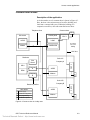
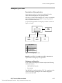
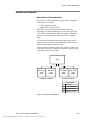
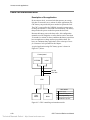
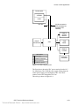
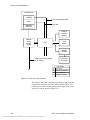
Basic equipment
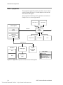
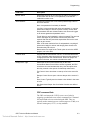
The equipment required for a basic, networked, access control
system is shown in Figure 3-1. In this chapter, we discuss the
items shown in the figure.
The equipment needed for specific applications is detailed in
Chapter 4: Access control applications.
Input circuit 1
Input circuit 2
Control panel
SAC bus
3-SAC
Security Access Control
Module
CRC
Card Reader
Controller
3-MODCOM
Modem Communication
Module
Output circuit
Card reader
Lock
Telephone lines
Distributor
ACDB program
SDU
Central
monitoring
station
Other factors
X Power supply
RPM
X Hardware configuration
Resource
profile
X SDU programming
X
ACDB/KDC operation
Figure 3-1: Equipment required for a basic access control system
3.2
Technical Manuals Online! - http://www.tech-man.com
CRC Technical Reference Manual
Hardware and equipment
Control panel modules
3-SAC Security Access Control module
The 3-SAC Security Access Control rail module controls a highspeed RS-485 circuit called the Security Access Control (SAC)
bus. The SAC bus supports fire, security, and access control
devices.
The 3-SAC handles message traffic for these devices. Events are
passed from the devices to the 3-SAC module, then to the
3-CPU1 for processing.
The 3-SAC has two sets of bus circuit terminals, and is capable
of Class A or Class B configuration. Each Class B circuit can
include 31 devices, for a total of 62 devices per module. Class A
circuits can include 30 devices total. In Figure 3-1, we show a
Class B bus with a CRC Card Reader Controller module.
3-MODCOM Modem Communicator module
The 3-MODCOM Modem Communicator module has both
modem and dialer functions. It can transmit and receive
information.
The 3-MODCOM can transmit alarm, supervisory, or trouble
messages to a remote central monitoring station using one or two
telephone lines. A variation of the module (3-MODCOMP) can
transmit pager messages to a paging company using the TAP
protocol.
The module can also receive information sent over telephone
lines by the Access Control Database (ACDB) program.
CRC Technical Reference Manual
Technical Manuals Online! - http://www.tech-man.com
3.3
Hardware and equipment
SAC bus and wiring
SAC bus
Since our security and access control devices require 24 Vdc, we
suggest that you always use a four-wire cable for the SAC bus
and a 24 Vdc power supply.
For the data wires, use unshielded, twisted pair, with greater
than 6 twists per foot, in 14 to 22 AWG (1.50 to 0.25 sq mm).
For the power wires, use 14 or 16 AWG.
You can use a four-conductor cable with an overall jacket
containing solid 2-19 AWG and 2-16 AWG for the SAC bus.
The maximum run from a CRC to the 3-SAC is 4,000 ft
(1,220 m) at 25 pF/ft. The maximum total capacitance of the run
is 0.1 µF, and the maximum total resistance is 52 Ω.
Card reader wire
Eight-conductor stranded 22 AWG cable with overall shield is
recommended for the cable from the CRC to the card reader.
3.4
Technical Manuals Online! - http://www.tech-man.com
CRC Technical Reference Manual
Hardware and equipment
CRC connections and options
CRC Card Reader Controller
The Card Reader Controller (CRC) is used for interfacing a card
reader into an integrated security and fire alarm system. One
CRC is required for each door you want to control. The CRC has
a terminal strip for connections to the following:
•
•
•
•
•
•
•
•
•
24 Vdc power
Strike (or other lock type)
Relay contacts
Card reader power
Card reader data
Card reader LEDs (two)
Optional sounder
SAC bus
Input loops 1 and 2
Each CRC supports:
•
•
•
•
•
8,000 cardholders
5,000 events
1,200 access levels (255 per company)
1,200 schedules (255 per company)
1,200 holidays (255 per company)
Each CRCXM supports:
•
•
•
•
•
36,000 cardholders
20,000 events
1,200 access levels (255 per company)
1,200 schedules (255 per company)
1,200 holidays (255 per company)
The CRC module performs all access decision processing. Each
CRC stores an access database and is capable of granting or
denying entry without external communication.
When entry is granted, the CRC applies or removes power to the
strike or maglock to unlock the door. The CRC is also capable of
unlocking a door on activation of a manual push button.
Each CRC stores access control information and records of the
events for the door it controls. The CRCXM model features
enhanced storage capacity.
Using its internal battery, the CRC can continue processing
access events even if there is a loss of communication or
primary power.
CRC Technical Reference Manual
Technical Manuals Online! - http://www.tech-man.com
3.5
Hardware and equipment
Input circuits 1 and 2
Each CRC supports two input circuits for such devices as:
•
•
•
•
Door contacts
Motion detectors
Request to exit buttons
Security devices
A door contact device monitors the door position (open or
closed) for various applications.
A motion detector detects a person’s approach and can be used
to unlock the door.
A request to exit (REX) push button (or bar) can be used to
manually unlock the door.
Security devices, such as glass-break detectors can be associated
with the door to enhance its security, or to monitor a nearby
window.
Output circuit
Each CRC supports one output circuit in the form of N.O. and
N.C. dry contact connections. The output circuit can be used for
such devices as:
•
•
•
Automatic door openers
Fan and damper control
Door holder control
Lock
The CRC supports any type of door locking device. Common
lock devices are strikes and maglocks. A strike opens the door
when power is supplied, while a maglock secures the door while
power is supplied.
CRC options
CRCSND CRC Sounder
The CRC Sounder is a small horn that mounts inside the card
reader controller module. The sounder operates if an emergency
exit door is opened without an exit request and can also indicate
that a door has been left open. The sounder clips to the inside of
the CRC cover.
The CRC Sounder can be programmed, using rules written in the
SDU. Further, the ACDB program can control several operating
parameters of the sounder.
3.6
Technical Manuals Online! - http://www.tech-man.com
CRC Technical Reference Manual
Hardware and equipment
CRCRL CRC Accessory Relay
The CRCRL is an accessory relay for the CRC(XM) Card
Reader Controller. Use the CRCRL in conjunction with an
external power supply to control a lock which requires voltage
or current outside the CRC's operating range.
CRC battery
Each CRC has space for an internal, 1.2 Ah, sealed lead-acid
battery. The battery supplies power to the CRC and its
peripherals, and provides local standby power.
The CRC battery provides 30 minutes of standby power for
access control functions and up to 4 hours for security functions.
The battery cannot be used for fire applications.
The following is a list of compatible batteries:
Manufacturer
Model number
AH
Edward Systems Technology
12V1A2
1.2
PowerSonic
PS-1212
1.2
Technacell
PS1212
1.2
Yuasa
NP1.2-12
1.2
Panasonic
LCR12V1.3P
1.3
Empire
NP 1.2-12
1.3
NewMax
FNC 1212
1.2
Interstate
PC1212
1.2
B&B Battery
BP1.2-12
1.2
Rocket G&Y
ES 1.2-12
1.2
DiaMec
DM 12-1.3
1.3
Long
WP 1.2-12
1.3
Union
MX12012
1.2
GS Portalac
PE12V1.2
1.2
CRCXF - CRC Transformer
The CRCXF - CRC Transformer is a 16.5 Vac transformer that
can power the CRC or CRCXM. It provides local power for
applications requiring additional power at door lock. The CRC
has ac load terminals for easy connection to transformer.
Be sure to check the CRC installation sheet for a list of
applications that prohibit the use of the CRCXF.
CRC Technical Reference Manual
Technical Manuals Online! - http://www.tech-man.com
3.7
Hardware and equipment
Cypress CVT-2110
The Cypress CVT-2110 converts Wiegand data to RS-232
ASCII hexadecimal.
You can use the CVT2110 to connect a card reader to a serial
port on the ACDB computer. This means you can read a card
number directly into the ACDB program by swiping the card,
rather than by typing.
The CVT-2110 requires an external source of voltage between 8
and 24 Vdc at 150 mA. It is available from Cypress Computer
Systems, Inc. (www.cypresscom.com).
3.8
Technical Manuals Online! - http://www.tech-man.com
CRC Technical Reference Manual
Hardware and equipment
Card readers and access cards
Card readers
By card reader, we mean any of the different types of credential
reader supported by the CRC. A card reader scans a card to
determine the card number and passes the card number to the
CRC.
All the required electronics are assembled in the card reader
housing. The card reader connects directly to the CRC, which
processes the card number and grants or denies access.
Each CRC can support several card readers. Typically, a CRC
will control an entry and exit card reader for the doorway. It can
also support multiple readers for such applications as two-person
rule or anti-passback.
Note that the CRC supports any type of reader that uses the
industry standard Wiegand output format. These include:
•
•
•
•
•
Proximity
Wiegand pin
Magnetic stripe
Keypad
Smart card
Some applications work best with card readers that support dual
LED control. The CRC uses two LEDs, or two LED states, to
indicate that further actions are required after the initial badging
operation, before access is granted. These applications are:
•
•
•
Two-person rule
Visitor and escort
PIN schedule
If you plan one of these applications, contact the card reader
manufacturer to confirm that the reader supports dual LED
control.
Card readers are additionally categorized by the way the card
must be presented to the card reader for reading:
•
Card swipe: The card swipe reader does its reading as a card
is swiped through a slot in the reader.
•
Insert: The insert reader requires that the card be inserted
fully into a narrow slot, with the reading typically being
done as the card is withdrawn.
•
Proximity: The proximity reader requires the user to pass the
coded card in close proximity to the reader, with the reader
using RF energy to determine the code on the card.
CRC Technical Reference Manual
Technical Manuals Online! - http://www.tech-man.com
3.9
Hardware and equipment
Some card readers are also equipped with a keypad. The keypad
allows for entry of a PIN number in addition to the card code.
The CRC can accommodate any PIN number of 1-4 digits along
with the associated card code. The need to enter a PIN is
controlled by two factors: whether or not the access schedule
calls for use of a PIN, and whether or not the partition to which
the CRC belongs is armed.
Card readers may come with an LED arrangement to visually
inform the user of the card reading and access control status.
Typically, an LED arrangement uses red and green LED
lighting. Some readers use a bicolor LED and others use two
separate LEDs. On most card readers the red LED is normally
lit; this serves as an indication that the reader is receiving power.
When a card is read, the LED temporarily turns from red to
green.
The CRC can provide 12 Vdc at 0.5A for operating its card
readers.
Note: For a list of compatible card readers, see the CRC
installation sheet.
Access cards
With the correct card reader, the CRC can process the following
types of access cards:
•
•
•
Wiegand
Magnetic stripe
Proximity
Note: For a list of compatible access cards, see the CRC
installation sheet.
3.10
Technical Manuals Online! - http://www.tech-man.com
CRC Technical Reference Manual
Hardware and equipment
Software packages
Resource Profile Manager (RPM) tool
The Resource Profile Manager (RPM) tool is part of the SDU. It
uses the project database to create a separate resource profile for
each company that will be using the access control system.
The resource profile defines the access control system for the
ACDB program. It includes detailed information about each
CRC used by a given company. For example:
•
•
•
•
•
•
•
Communication method
Primary or secondary control
Number of cardholders
Number of schedules
Number of holidays
Number of access levels
Command lists used
Access Control Database (ACDB) program
The Access Control Database (ACDB) program lets the user
define and maintain a database of information about CRCs,
cardholders, schedules, and access levels.
The ACDB program runs on the user’s PC. Additions or updates
to the access control database can be transmitted to the CRC
units in two ways.
The first method is via modem and dial-up telephone line to the
3-MODCOM. The information is then routed to the 3-CPU1,
through the correct 3-SACs, and finally to the CRC units.
The second method is by connecting the user’s PC directly to the
3-CPU1 using an RS-232 cable. The connection is made
between the PC’s COM1 port and any of the RS-232 terminals
on the 3-CPU1. As in the first method, after reaching the
3-CPU1 additions and changes are routed through the correct
3-SACs to the CRCs.
Note: Changes to the access control database have no impact on
the parameters or operations of listed fire system equipment.
Different versions of the ACDB software are available
according to your system configuration and the number of doors
you need to control. These are described below.
ACDB8
ACDB8 is a software package that lets you enroll 50,000
cardholders in an EST3 network system with eight or less doors.
CRC Technical Reference Manual
Technical Manuals Online! - http://www.tech-man.com
3.11
Hardware and equipment
ACDB8+
ACDB8+ is a software package that lets you enroll 50,000
cardholders in a networked EST3 system with over 4,000 doors.
ACDB-SVR
ACDB-SVR is the Access Control Database Server Application
Software. This is installed on the server PC for connection of
additional Access Control Database client machines. This
version provides the same graphical user interface for cardholder
enrollment and database configuration.
ACDB-CLNT
ACDB-CLNT is the Access Control Database Client
Application Software. This allows client machines to
communicate with the ACDB-SVR database for use with
additional workstations.
3.12
Technical Manuals Online! - http://www.tech-man.com
CRC Technical Reference Manual
Chapter 4
Access control applications
Summary
The CRC is a powerful and flexible component of access control
systems. While it is a central component of such systems, it
cannot work in isolation. This chapter shows how the CRC
interacts with other components and modules.
This chapter also illustrates and describes several access control
applications. Each application is presented as a separate topic
that includes a block diagram and description. These give you an
overview of the application, and show the components required
and their interconnection.
Refer to the EST3 Installation Sheets for specific component
settings and terminal connections.
Content
Other factors • 4.2
Anti-passback • 4.4
Central monitoring station • 4.7
Common door access • 4.9
Delayed egress • 4.11
Elevator control • 4.14
Emergency exit door • 4.17
Handicap access door • 4.19
Maglock peripherals • 4.21
Multiple card readers • 4.23
Muster • 4.25
Power for continuous locks • 4.28
Power for intermittent locks • 4.30
Power from an ac source • 4.32
Power from a remote source • 4.35
Remote controls • 4.38
Two-person rule • 4.40
CRC Technical Reference Manual
Technical Manuals Online! - http://www.tech-man.com
4.1
Access control applications
Other factors
Each of the application drawings in this chapter includes a
callout box for other factors that should be considered. These
are:
•
•
•
•
Power supply
Hardware configuration
SDU programming
ACDB/KDC operation
Power supply
The CRC is designed to operate on 24 Vdc. For this reason, we
recommend that you include power from the panel with the SAC
bus cable. You can use the panel 3-PPS/M or 3-BPS/M power
supplies.
When using a transformer power supply you must provide a
circuit common path between all devices, using the –24 Vdc
terminals.
If you use an additional power supply other than the CRCXF,
that power supply must be listed for fire alarm applications, must
have ground fault detection disabled, and must have a circuit
ground (circuit common) that is isolated from earth ground.
Hardware configuration
The CRC has two jumpers that configure the power source and
usage for the module. See the CRC installation sheet for details
on the jumper settings.
No other configuration settings are made at the device itself. All
other configuration is done via SDU or ACDB programming.
The SDU determines site-level configuration and parameters.
The ACDB program controls end-user settings.
SDU programming
While the ACDB program defines the access control database,
all other definition, configuration, and programming for the
access control system happens in the SDU.
The SDU controls the general configuration of the 3-SAC
modules, plus the configuration of all CRC devices on the SAC
busses.
CRC modules can be configured to execute a specific,
predefined command list when a specific access control event
occurs. You write the command lists in the SDU, and assign
them to CRC events when you configure the CRC module.
4.2
Technical Manuals Online! - http://www.tech-man.com
CRC Technical Reference Manual
Access control applications
Partitions are fundamental groups used with access control
systems. To use such access control features as two-person rule,
muster, or anti-passback, CRCs must belong to the same
partition. All partitions are created and defined in the SDU, and
each CRC can be assigned to a partition.
For the 3-MODCOM module, the SDU determines the dialer and
modem parameters, defines the receivers and accounts, and
assigns each account to the correct receiver. These settings
control CMS reporting and ACDB download operation.
Finally, the SDU includes the RPM tool, described in Chapter 3.
ACDB operation
The ACDB program lets the end user create and revise his access
control database. Parameters stored in the database identify
cardholders, schedules, and holidays, and assign access
privileges.
The SDU includes a tool called the Resource Profile Manager
(RPM). The RPM lets you create a resource profile for each
company using the system for access control purposes. During
setup of the ACDB program, the user imports the resource
profile created by the RPM. This defines the system devices for
the ACDB program.
The ACDB runs on the end user’s computer. You can connect
the computer to the access control system in two ways:
•
From an RS-232 port on the computer to an RS-232 port on
the 3-CPU1
•
From the computer modem to a 3-MODCOM via telephone
lines
The end result is that the ACDB database can be downloaded
from the user’s computer to the system. Each CRC stores that
portion of the database pertinent to its operation.
Access control applications
The remaining topics in this chapter discuss specific access
control applications. Each topic gives you an overview of the
application, showing the components required and their
interconnection.
Each topic includes a block diagram and general description of
the application. Other factors (as called out on the drawings) are
discussed under separate headings in the topic.
CRC Technical Reference Manual
Technical Manuals Online! - http://www.tech-man.com
4.3
Access control applications
Anti-passback
Description of the application
Anti-passback is a feature of the access control system that
prevents successive use of one card to pass through any door in
the same direction. Anti-passback prevents a card from being
passed back to another person for the purpose of gaining
unauthorized access.
The CRC supports three forms of anti-passback:
•
•
•
Strict
Logged
Timed
Strict anti-passback is the most restrictive form of anti-passback.
It requires all personnel to badge in and out, denying them access
to an area when they fail to do so.
Logged anti-passback is less restrictive than strict anti-passback.
It still requires personnel to badge in and out but does not deny
access when anti-passback rules are violated. Rather, such access
is logged as an access granted anti-passback event. With logged
anti-passback, security staff can work to correct violations, but
personnel are not locked out.
Timed anti-passback prevents reuse of a card for a specific
period, but does not require personnel to badge out. A timed
anti-passback system automatically badges a cardholder out of
the controlled partition after a specified time period, allowing the
card to be used again.
Note: Timed anti-passback cannot be used with a muster
application, since the system automatically logs cardholders out
of the partition, defeating muster accounting.
To implement anti-passback, a separate CRC is required at each
doorway in the controlled partition. Each doorway requires an
outside card reader. Strict and logged anti-passback applications
also require an inside reader at every doorway. Timed antipassback does not require the use of an inside card reader.
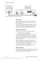
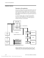
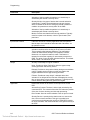
A typical anti-passback application is shown in Figure 4-1,
below.
The figure shows a building with a perimeter fence. It would be
easy for an employee to pass his access card to an unauthorized
individual through the fence, thereby allowing access.
Configuring the access control system for anti-passback
operation can help prevent this from happening.
4.4
Technical Manuals Online! - http://www.tech-man.com
CRC Technical Reference Manual
Access control applications
Entrance
turnstile
Perimeter fence
Outside
reader
Inside
reader
Lock circuit
SITE
Reader circuit
Building
entrance
CRC
SAC bus
Main building
Control panel
3-SAC
Emergency
exit
Other factors
Power supply
X Hardware configuration
X SDU programming
X ACDB/KDC operation
Figure 4-1: Anti-passback
Hardware configuration
The control panel must contain a 3-SAC Security Access Control
module. The 3-SAC module supports the SAC bus. Power for
the CRC can be taken from the 3-PPS/M and routed with the
data lines in a cable composed of two twisted-pair wires (the
SAC bus).
CRC Technical Reference Manual
Technical Manuals Online! - http://www.tech-man.com
4.5
Access control applications
SDU programming
If the CRC is to be used for anti-passback this must be
configured using the SDU. The CRC configuration dialogs let
you select the type of anti-passback you want to use:
•
•
•
•
None
Logged
Timed
Strict
You can also assign a predefined command list to various access
granted or access denied events, including the anti-passback
events:
•
•
Access granted anti-passback
Access denied anti-passback
The 3-CPU1 runs the command list you specify when either of
these events occurs.
ACDB programming
With timed anti-passback, the cardholder is automatically
marked out after a specified period of time. This period is
defined by the ACDB. The period can be set from 0 through 255
minutes (4 hours and 15 minutes).
4.6
Technical Manuals Online! - http://www.tech-man.com
CRC Technical Reference Manual
Access control applications
Central monitoring station
Description of the application
An access control system can transmit different kinds of event
information to a central monitoring station (CMS). The basics
for such a system are shown in Figure 4-2.
Card
reader
CRC
SAC bus
Control panel
Access denied event
3-SAC
3-CPU1
Programmed rules
for transmission
3-MODCOM
Formatted CMS message
Telephone line
Other factors
Power supply
Hardware configuration
X
SDU programming
ACDB/KDC operation
Central
monitoring
station
Figure 4-2: Access control reporting to a central monitoring
station
When a reportable access event occurs, the event message travels
from the CRC to the 3-SAC. The 3-SAC passes the message to
the 3-CPU1 which executes a predefined command list. The
command list specifies the details of the message that is sent to
the 3-MODCOM for transmission to the CMS.
CRC Technical Reference Manual
Technical Manuals Online! - http://www.tech-man.com
4.7
Access control applications
SDU programming
Reporting access control events to a CMS depends entirely on
programming and the creation of command lists. In essence, you
must assign a command list to each CRC event you want to
report. The command list contains the details of the message to
be transmitted.
The following CRC events can be assigned command lists:
•
•
•
•
•
•
•
•
•
•
•
•
•
•
•
Access granted
Access granted irregular
Access granted anti-passback
Access granted muster
Access denied unknown
Access denied reader disabled
Access denied access level not active
Access denied outside schedule 1
Access denied outside schedule 2
Access denied partition armed
Access denied PIN not entered
Access denied PIN not valid
Access denied two-person timeout
Access denied anti-passback
Access denied escort
4.8
Technical Manuals Online! - http://www.tech-man.com
CRC Technical Reference Manual
Access control applications
Common door access
Description of the application
A site that makes use of a common door is shown in Figure 4-3.
Here, the door is the main entrance of an office building, and
leads into a common lobby area. Within the building, two
companies rent offices, each with controlled access doors.
Common door
Telephone lines
CR 1
Site owner
Control panel
ACDB
3-SAC
Modem
3-MODCOM
CRC 1
SITE
Lobby
SAC bus
Distributor
Suite 101
Site
Owner
CRC 2
Company A
SDU
Company
A
ACDB
RPM
Modem
CR 2
Company
B
Suite 102
Other factors
ACDB
CRC 3
Company B
Resource profiles
X Hardware configuration
X SDU programming
X ACDB/KDC operation
Modem
CR 3
Power supply
Figure 4-3: Common door in a lobby area
CRC Technical Reference Manual
Technical Manuals Online! - http://www.tech-man.com
4.9
Access control applications
Hardware configuration
The site has an EST3 control panel that includes a 3-SAC and a
3-MODCOM module. The 3-SAC supports the SAC bus. The
3-MODCOM module supports modem communication with the
control panel over telephone lines.
SDU programming
As the distributor, you use the SDU to program the EST panel
for this application. Part of the programming job is to use the
Resource Profile Manager (RPM) to create resource profiles for
the site owner and for each tenant company.
Resource profiles are imported into the Access Control Database
(ACDB) program. They determine which devices the user can
see and program. Resource profiles also establish transmission
routes that permit modem communication with the EST3 panel.
When a device is shared, the RPM lets you specify how much of
the device is allocated to each company. You can allocate
resources either by percentages or by actual numbers.
It’s a good idea to hold some allocation in reserve, giving each
company only what it needs. It is much easier to allocate
additional resources as needed than to reclaim resources that are
already allocated.
In our example, the resource profile for company A would
contain CRC 1 (the lobby door) and CRC 2 (the suite 101 door).
For Company A, you might choose to allocate 80% of CRC 2,
and 20% of CRC 1.
Similarly, the resource profile for company B would allocate
80% of CRC 3 and another 20% of CRC 1.
The site owner will need access to the CRC2 and CRC3 doors
for cleaning or inspection purposes. The site owner resource
profile could allocate 20% of CRC 1, 10 % of CRC 2, and 10%
of CRC 3.
This leaves 40% of CRC1 unallocated, and 10% of CRC2 and
CRC3 unallocated. The unallocated resources are reserved for
future expansion or changes.
ACDB operation
The site owner, the owner of company A, and the owner of
company B, can all use telephone lines to communicate with the
EST3 control panel via the 3-MODCOM module. They can
download additions and changes to the CRCs, and upload usage
data for various ACDB reports.
4.10
Technical Manuals Online! - http://www.tech-man.com
CRC Technical Reference Manual
Access control applications
Delayed egress
Description of the application
Delayed egress doors help to control shoplifting at retail sites. A
delayed egress door has card readers and a request to exit (REX)
switch. Employees can badge in and out as they would at any
other door. In an emergency, customers must press the REX
switch to unlock the door.
When the REX switch is activated, the CRC sounds the
CRCSND horn and sends a security alarm event to the panel. It
does not unlock the door immediately, thus allowing site staff
time to investigate.
The CRC waits for a specific interval of time before unlocking
the door. The typical delay time is 15 seconds; however, you
may be able to use a delay of up to 30 seconds with the approval
of the AHJ. The horn continues to sound for a specific period of
time, or until the CRC is reset.
After the delay time passes, the CRC unlocks the door, and
latches it in the unlocked state. The CRC must be reset in order
to relock the door and silence the horn. To reset the CRC, site
staff must use a valid badge at the card reader.
The CRC also activates the CRCSND horn if the door is opened
without badging. For example, if the door is forced open from
the outside, the CRCSND activates, even though the REX has
not been pressed.
Many codes require that delayed egress doors unlock during a
fire alarm, or when the panel is in trouble. This requirement
allows occupants to evacuate the site immediately when a fire is
detected, or when the panel loses its ability to detect a fire or
sound the alarm.
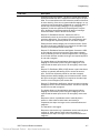
Figure 4-4 shows a delayed egress door with inside and outside
card readers and a request to exit switch. The CRC uses a door
contact switch to determine the position of the door, and a
maglock to lock the door. The door contact switch and REX
switch are connected to the input loops of the CRC.
Note: Refer to NFPA 101 and the local AHJ to determine the
requirements for delayed egress applications.
CRC Technical Reference Manual
Technical Manuals Online! - http://www.tech-man.com
4.11
Access control applications
Card
reader
inside
CRC
CRCSND
Door
contact
Card
reader
outside
Maglock
REX
switch
Other factors
Power supply
X
Hardware configuration
X
SDU programming
X
ACDB/KDC operation
Figure 4-4: Delayed egress doorway
Hardware configuration
A maglock is most commonly used for delayed egress
applications, but you can use any locking device that has no
manual override. For example, a strike with no knob could be
used.
The door contact is used to detect unauthorized opening of the
door. The CRC activates the CRCSND and reports a security
alarm event when the door is opened without badging or use of
the REX.
The door contact signal is also required to relock the door when
the CRC is reset. The lock cannot be reset until the door is
closed.
SDU programming
Most codes require you to program rules that unlock the door
when the panel goes into alarm or when the panel goes into
trouble.
When configuring the CRC, set the Delayed Egress Time field to
the value (in seconds) you want to use. Define the input circuits
as follows.
4.12
Technical Manuals Online! - http://www.tech-man.com
CRC Technical Reference Manual
Access control applications
For the door contact input loop:
•
•
•
•
•
•
Device Type = Security P Monitor
Input Circuit Partition = as determined by project
Max Delta Count = as determined by project
Delays = None
Application = Emergency Exit Door Contact
Personality = Basic
For the request to exit switch:
•
•
•
•
•
•
Device Type = Monitor
Input Circuit Partition = None
Max Delta Count = not applicable
Delays = None
Application = Request to Exit with Delayed Egress
Personality = N.O. with Trouble
ACDB operation
When an employee badges in or out at the door, the CRC
bypasses the door contact for a specified period of time. This is
called the Bypass Time, and is specified in the ACDB.
The duration of the CRCSND horn is also specified in the
ACDB, as the Emergency Exit Sounder Time. This can be set to
any value between 0 and 255 seconds.
Setting the value to 0 seconds effectively inhibits the CRCSND.
Setting the value to 255 seconds programs the CRC to operate
the CRCSND until the CRC is manually reset by badging at the
CRC card reader.
CRC Technical Reference Manual
Technical Manuals Online! - http://www.tech-man.com
4.13
Access control applications
Elevator control
Description of the application
An access control system can determine which floors are
available to a given cardholder. This application is shown in
Figure 4-5.
A CRC and independent power source are installed in the
elevator cab. When a cardholder presents his card, it is processed
by the CRC. If valid, the CRC sends an access granted event and
a command list request to the 3-CPU1 via the 3-SAC.
The command list operates the Signature relay modules attached
to the Signature Controller module. The relays are connected to
the elevator controller, and turn on or off access to the correct
floors, according to the cardholder’s access level privileges.
The command list includes timing, so the cardholder has a
limited window of opportunity during which he can press the
desired floor button. After the time has lapsed, he must present
his card again.
Note: This application must be used only for floor access, and
NOT for elevator control.
4.14
Technical Manuals Online! - http://www.tech-man.com
CRC Technical Reference Manual
Access control applications
Elevator room
Elevator controller
SIGA-CR
Floor enabling
circuits
SIGA-CR
SIGA-CR
Elevator
traveller cable
Signature data circuit
Electrical room
Elevator line
SAC bus (using two
spare twisted pairs)
Control panel
Signature
Controller
3-CPU1
3-SAC
Elevator cab
Operator
panel
CRC
Other factors
Card
reader
CRCXF
Transformer
X Power supply
X Hardware configuration
X SDU programming
X ACDB/KDC operation
Figure 4-5: Access control and elevators
CRC Technical Reference Manual
Technical Manuals Online! - http://www.tech-man.com
4.15
Access control applications
Power supply
The figure shows an independent power source for the CRC.
This is suggested due to the length of cable from the cab to the
electrical room.
Two pairs of wires are used to connect the CRC to the control
panel. The SAC bus requires one pair for data communication.
One wire of the second pair is required to maintain a common
ground between the control panel and the CRC. For details, refer
to the topic Power from an ac source, later in this chapter.
If you use an additional power supply other than the CRCXF,
that power supply must be listed for fire alarm applications, must
have ground fault detection disabled, and must have a circuit
ground (circuit common) that is isolated from earth ground.
Hardware configuration
In this application, none of the CRC input circuits or relay
contacts are used. The CRC simply reads the card and passes the
command list request to the 3-SAC and 3-CPU1 for processing.
Since the CRC lock and input circuits are not used, you must
provide dummy loads to maintain correct supervision currents.
See the installation sheet for the correct load values.
SDU programming
The SDU programmer must create a command list for each
combination of floors desired.
ACDB operation
The site security officer determines which floors should be
accessible for an access level, and assigns the correct command
list to the access granted event for that level. The site security
officer also determines which cardholders belong to each access
level.
4.16
Technical Manuals Online! - http://www.tech-man.com
CRC Technical Reference Manual
Access control applications
Emergency exit door
Description of the application
An emergency exit door is a door that is unlocked from the
inside either by badging out or by opening the door.
If the door is opened without badging out, it causes an immediate
alarm. Badging out bypasses the door for a specific period of
time, so no alarm event occurs.
A typical CRC application for emergency exit door is shown in
Figure 4-6, below.
CRC
Door
contact
CRCSND
Card
reader
outside
Card
reader
inside
Strike
Other factors
Power supply
X
Hardware configuration
X
SDU programming
X
ACDB/KDC operation
Figure 4-6: Emergency exit door
Note: Refer to NFPA 101 and the local AHJ to determine the
requirements for emergency exit applications.
Hardware configuration
A CRC used for an emergency exit door requires the following
additional hardware:
•
CRCSND CRC Sounder
•
Door contact
The CRCSND is installed inside the CRC. The sounder provides
a local sound alarm. Opening the door without badging out
activates the CRCSND.
CRC Technical Reference Manual
Technical Manuals Online! - http://www.tech-man.com
4.17
Access control applications
The door contact is connected to the CRC via the input circuit.
SDU programming
In the SDU, you’ll need to define the input circuit for the door
contact as follows:
•
•
•
•
Device type: Security P Monitor
Delays: None
Application: Door Contact
Personality: Basic
ACDB operation
Two time periods are defined in the ACDB: Emergency Exit
Sounder Time, and Bypass Time.
Emergency Exit Sounder Time is the number of seconds (0
through 255) the CRC Sounder sounds when an emergency exit
door is opened without badging out.
When set to zero, the sounder is disabled. When set to 255, the
sounder sounds until manually reset. The sounder is reset when a
cardholder badges in at the door.
In all cases badging in on the affected CRC can silence the
sounder.
Bypass Time is the number of seconds (0 through 255) that the
door is bypassed after a cardholder badges out.
4.18
Technical Manuals Online! - http://www.tech-man.com
CRC Technical Reference Manual
Access control applications
Handicap access door
Description of application
A handicap access door is a door that allows a handicapped
person the ability to enter and exit a door by allowing extra
access time and providing an automatic door opener.
The door can function for both normal access and handicap
access. A person without handicap privileges would operate the
door just as any other door.
When a person with handicap privileges badges in, the CRC
recognizes that the person has handicap privileges and provides
two extra benefits. The first is giving the handicap person extra
time to enter or exit the doorway before relocking the door. The
second is an automatic door opener.
A second card reader can be installed in parallel to the entry or
exit card reader to make it easier for a handicapped person to
reach. The second card reader should be placed at a lower level
and farther away from the door. The distance from the door
should allow the automatic door to open fully without a person
needing to move backwards.
Door
opener
CRC
Card
reader
outside
Card
reader
inside
Handicap
card reader
outside
Handicap
card reader
inside
Lock
Other factors
Power supply
X
Hardware configuration
X
SDU programming
X
ACDB/KDC operation
Figure 4-7: Handicap access door
CRC Technical Reference Manual
Technical Manuals Online! - http://www.tech-man.com
4.19
Access control applications
Note: Refer to the appropriate ADA codes and the local AHJ to
determine the requirements for handicap access door
applications.
Hardware configuration
A CRC used for a handicap access door may require the
following additional hardware:
•
•
Automatic door opener
Additional card readers
The automatic door opener is installed directly to the access
door. The CRC controls the opening of the door with its internal
relay.
Caution: The CRC relay is for low-voltage only. Do not exceed
the relay limits stated on the installation sheet.
The additional card readers are wired to the standard card readers
in parallel.
SDU programming
In the SDU, you’ll need to define the CRC relay device type as
Access Door Motor Control. This will activate the door opener
for the time specified by the ACDB.
ACDB operation
The Relay Open Time is defined in the ACDB. This is the
number of seconds (0 through 255) that the CRC activates the
relay that automatically opens the door. The default is 30
seconds.
The Handicap Unlock time is also defined in the ACDB. This is
the number of seconds (0 through 255) that the lock stays
unlocked. The default is 20 seconds The door relocks when the
unlock time has expired and the door has closed.
Both of these times can be set to allow a longer access time for a
handicapped person.
4.20
Technical Manuals Online! - http://www.tech-man.com
CRC Technical Reference Manual
Access control applications
Maglock peripherals
Description of the application
Maglocks require maglock peripherals due to NFPA codes. In
general, these devices are intended to ensure that an egress door
secured with a maglock can always be opened in an emergency.
Figure 4-8 shows the CRC using a maglock and required
peripherals.
Maglock application requires a passive infrared motion detector
(PIR) to be mounted above the door. Also required is a request to
exit button (REX) to be mounted within five feet of the door and
40 to 48 inches above the ground. The PIR is connected on the
input circuit of the CRC. The REX is connected directly to the
maglock so that when activated it unlocks the door
independently of the CRC.
The CRC is designed so that on detection of a fault on the input
circuit of the PIR, the door will unlock. The PIR detects an
approaching body and unlocks the door. Similarly, the REX
button unlocks the door when it is pressed. The REX button must
unlock the door for a minimum of 30 seconds.
CRC
Passive
infrared
detector
Other factors
Power supply
X
Hardware configuration
X
SDU programming
Maglock
Request to
exit button
ACDB/KDC operation
Figure 4-8: Maglock and peripherals
CRC Technical Reference Manual
Technical Manuals Online! - http://www.tech-man.com
4.21
Access control applications
Hardware configuration
The maglock peripherals consist of the following:
•
•
Passive infrared motion detector (PIR)
Request to exit button (REX)
The PIR is connected via the CRC input circuit. The REX is
connected directly to the maglock instead of the CRC input
circuit to meet NFPA requirements.
SDU programming
When programming the system for this application you’ll need
to configure the CRC, defining the device types. You’ll also
need to define the input circuits. For this application define the
input circuit for the PIR as follows:
•
•
Device type = Security interior
Application = Request to exit motion detector.
4.22
Technical Manuals Online! - http://www.tech-man.com
CRC Technical Reference Manual
Access control applications
Multiple card readers
Description of the application
Several access control applications require the use of multiple
card readers. For example:
•
•
Visitor and escort readers
High and low position readers
The CRC lets you use multiple card readers of the same
technology or of mixed technologies. It can support up to four
card readers, provided that the total current draw of the readers
does not exceed the limits specified on the CRC installation
sheet.
A visitor and escort application using multiple card readers is
shown in Figure 4-9, below. In this application, both the escort
and visitor must badge in to gain access.
The escort has a permanent, plastic card, and uses the proximity
card reader. The visitor is issued an inexpensive paper bar code
card, and uses the bar code reader.
CRC
Proximity
card
reader
Bar code
card
reader
Outside card readers
Proximity
card
reader
Bar code
card
reader
Inside card readers
Other factors
Power supply
X Hardware configuration
X SDU programming
X ACDB/KDC operation
Figure 4-9: Multiple card readers
CRC Technical Reference Manual
Technical Manuals Online! - http://www.tech-man.com
4.23
Access control applications
Card reader
This application works best with card readers that support dual
LED control. The CRC uses the second LED (or LED state) to
signal the visitor that the escort must badge in before access is
granted.
Hardware configuration
The proximity card reader and barcode card reader are connected
to the same terminals of the CRC.
SDU programming
When an escorted visitor tries to enter a controlled area without
an employee, the CRC generates an access denied escort event.
You can select a predefined command list that the 3-CPU1
executes in response to this event.
ACDB operation
Like employees, visitors must be assigned an access level using
the ACDB. The site security officer can elect to assign the same
access level to all visitor cards, or assign different access levels
to ranges of visitor cards.
4.24
Technical Manuals Online! - http://www.tech-man.com
CRC Technical Reference Manual
Access control applications
Muster
Description of the application
The muster application can be used to determine who has exited
the building in the event of an evacuation.
During normal operations, staff badge in and out using the inside
and outside readers. Note that muster reporting will only work if
all employees badge in and out.
During an evacuation, everyone exits the building immediately
and goes to one of the predetermined muster stations. At the
muster station personnel badge in using a reader that is attached
to a CRC designated as a muster station.
After everyone has badged in at the muster station security staff
use the ACDB program to create a muster report. The report lists
staff who badged into the building but did not badge out at a
muster station.
Figure 4-10 shows a typical muster application. CRCs 2, 3, 5,
and 6 are normal access control CRCs. CRCs 1 and 4 are muster
station CRCs.
The ACDB computer must be located in a safe area so security
staff can create the muster report after the evacuation. This
computer can connect to the access control system either via
telephone lines and a 3-MODCOM, or by direct connection to
the EST3 control panel.
Note: Links between the ACDB computer and the control panel
should be tested regularly to ensure correct operation.
Staff must be made aware of the importance of badging in and
out at all times. Failure to do so can result in a false muster
report, indicating that someone is still in the building. This in
turn can result in rescue personnel risking danger to search for
someone who is not actually in the building.
CRC Technical Reference Manual
Technical Manuals Online! - http://www.tech-man.com
4.25
Access control applications
Muster station
Card reader
Entrance
CRC 2
Entrance
CR outside
CR inside
CR outside
CR inside
CRC 3
CRC 1
SAC bus
Control panel
3-SAC
3-PPS/M
MODCOM
CR inside
CR outside
CRC 4
CRC 6
CRC 5
CR inside
CR outside
Emergency
exit
Emergency
exit
Telephone line
Other factors
Muster report
station
Card reader
X Power supply
X Hardware configuration
Muster station
ACDB
X SDU programming
X ACDB/KDC operation
Figure 4-10: Muster application
4.26
Technical Manuals Online! - http://www.tech-man.com
CRC Technical Reference Manual
Access control applications
Hardware configuration
The control panel must contain the following rail modules:
•
•
3-SAC Security Access Control module
3-PPS/M Primary Power Supply module
•
3-MODCOM Modem Communication module
— or —
3-RS232 Card option installed in the 3-CPU1
The 3-SAC module supports the SAC bus. Power for the CRC is
normally taken from the 3-PPS/M and is routed with the data
lines in a cable composed of two twisted-pair wires.
The 3-MODCOM module supports modem communication
between the control panel and the ACDB program via telephone
lines. Alternately, the 3-RS232 Card supports RS-232
communications on a cable connected directly to the 3-CPU1.
All CRCs controlled by a muster station must be on the same
3-SAC card as the muster station. Badging out at a muster station
badges the person out of all partitions for that 3-SAC card.
Therefore, a single muster station can serve multiple partitions,
provided that they are on the same 3-SAC card.
The system must have at least one muster CRC per 3-SAC
module. The system cannot exchange muster information
between 3-SAC modules, so each must be handled separately for
muster purposes.
A CRC used for a muster station requires the specified dummy
load on the lock terminals to maintain supervision. (Refer to the
CRC installation sheet for correct resistor values.)
The card reader used for the muster station must be wired as an
outside reader.
SDU programming
Each CRC used in a muster application requires specific
configuration settings. These are made in the SDU program, on
the CRC Configuration tab.
If the CRC is used in a partition that has muster control, check
the Muster Support box.
For the CRC designated as the muster station, check the Muster
Station box, but leave the Muster Support box clear.
In the SDU, you can also assign a predefined command list to
the Access Granted Muster event.
CRC Technical Reference Manual
Technical Manuals Online! - http://www.tech-man.com
4.27
Access control applications
Power for continuous locks
Description of the application
By continuous locks, we mean locks that operate, on average,
more than 30 seconds in every minute. Normally, power for the
lock is taken from the CRC battery. However, for continuous
locks there is not enough recharge time for the CRC battery to
keep up with the drain. Consequently, the CRC must be
configured so that an external power supply operates the lock.
The CRC can be powered by the 3-PPS/M, by a CRCXF (CRC
Transformer), or by a remote 24 Vdc power supply. Any of these
supplies is suitable for powering continuous locks. (See the
topics Power from an ac source, Power from a remote source,
and the CRC - Card Reader Controller Installation Sheet for
more information about these options.)
A typical application using continuous locks is shown in Figure
4-11, below.
Control panel
3-PPS/M
3-SAC
24 Vdc
SAC bus
24 Vdc remote
power supply or
CRCXF
transformer
CRC
Other factors
X Power supply
Card
reader
Strike or
maglock
X Hardware configuration
X SDU programming
ACDB/KDC operation
Figure 4-11: CRC controlling a continuous lock
4.28
Technical Manuals Online! - http://www.tech-man.com
CRC Technical Reference Manual
Access control applications
The figure shows the power coming from the 3-PPS/M in the
control panel. This power supply could be used to operate the
lock, but use of a CRCXF or remote 24 Vdc supply is
recommended to minimize the load on the panel power supply.
During open schedules, or when an authorized card is read at a
card reader, the CRC provides power from the 3-PPS/M to the
door strike to unlock the door. For maglocks, the CRC provides
power from the 3-PPS/M (or CRCXF or 24 Vdc power supply)
to activate the lock during closed schedules, or between
authorized card accesses.
Power supply
Use power and load calculations to determine the need for
remote power supplies or transformers. Refer to Appendix A:
Calculations for calculation guidelines.
Jumper settings determine the power source and usage for the
CRC. Refer to the installation sheet for correct jumper settings.
Configure the input power as dc when using power from the
control panel or a remote supply. Configure input power as ac
when using a transformer.
For this application, configure the output power as continuous.
Hardware configuration
The control panel must contain the following rail modules:
•
•
3-SAC Security Access Control module
3-PPS/M Primary Power Supply module
The 3-SAC module supports the SAC bus. Power for the CRC is
taken from the 3-PPS/M and is routed with the data lines in a
cable composed of two twisted-pair wires.
SDU programming
When configuring the system for this application, you’ll need to
configure the CRC and define the appropriate lock type in the
SDU. For this application the Lock Type can be either Strike or
Maglock as required to match the lock actually used.
CRC Technical Reference Manual
Technical Manuals Online! - http://www.tech-man.com
4.29
Access control applications
Power for intermittent locks
Description of the application
By intermittent locks, we mean locks that operate, on average,
less than 30 seconds in every minute. In these applications, the
CRC battery can provide the power needed to operate the lock.
The CRC is powered by the 3-PPS/M. It uses this power source
to charge an internal 1.2 Ah sealed lead acid battery. The battery
then provides the power needed to operate the door lock..
Because the battery powers the door strike, this configuration
cannot be used for maglocks or strikes that are active more than
30 seconds in a minute. In these conditions the battery would not
have enough time to charge and keep up with the drain. For
heavy or continuous duty applications, refer to the topic Power
for continuous locks presented in this chapter.
A typical application using CRC battery power is shown in
Figure 4-12, below.
Control panel
3-PPS/M
3-SAC
24 Vdc
SAC bus
CRC
Other factors
X Power supply
Card
reader
X Hardware configuration
Strike
X SDU programming
X
ACDB/KDC operation
Figure 4-12: CRC controlling an intermittent strike
4.30
Technical Manuals Online! - http://www.tech-man.com
CRC Technical Reference Manual
Access control applications
The figure shows the charging power coming from the 3-PPS/M
in the control panel. The access control system requires a 24 Vdc
power supply to power the CRC and to charge its battery. The
3-SAC connects to the CRC through the SAC bus.
When an authorized card is read at a card reader, the CRC
provides power from its internal battery to the door strike and
unlocks the door.
Power supply
Jumper settings determine the power source and usage for the
CRC. Refer to the installation sheet for correct jumper settings.
Configure the input power as dc. Configure the output power as
intermittent.
Hardware configuration
The control panel must contain the following rail modules:
•
•
3-SAC Security Access Control module
3-PPS/M Primary Power Supply module
The 3-SAC module supports the SAC bus. Power for the CRC is
taken from the 3-PPS/M and is routed with the data lines in a
cable composed of two twisted-pair wires.
SDU programming
When configuring the system for this application, you’ll need to
configure the CRC and define the appropriate lock type in the
SDU. For this application set the Lock Type to Strike.
ACDB operation
Note that a CRC configured and programmed for intermittent
lock use cannot support an open schedule (a period when the
lock is kept open). Such a schedule would quickly drain the CRC
battery and the lock would close.
You should document the CRC configuration and include this in
your project plans. Make a copy of this documentation available
to the site security staff who will use the ACDB to create and
assign schedules.
CRC Technical Reference Manual
Technical Manuals Online! - http://www.tech-man.com
4.31
Access control applications
Power from an ac source
Description of the application
By ac power, we mean that the CRC provides the power to
operate the electric door strike or maglock by using a 16.5 Vac
transformer (model CRCXF). This supply can provide
continuous power to the door strike or maglock, and also power
the CRC.
Using an ac source:
•
•
•
Limits power drawn from the control panel
Supports continuous duty locks
Supports schedules with unlock periods
Note: Be sure to check the installation sheet for the CRC and
CRCXM Card Reader Controller (P/N: 387625) for a list of
applications that prohibit the use of the CRCXF.
A typical CRC using ac power is shown in Figure 4-13.
4.32
Technical Manuals Online! - http://www.tech-man.com
CRC Technical Reference Manual
Access control applications
Control panel
3-PPS/M
3-SAC
SAC bus
24 Vdc connects to
CRC terminals, but
bypasses CRC
internally
Passive
infrared
detector
CRCXF
Transformer
CRC
Card
reader
Maglock
or strike
Other factors
X
Power supply
X
Hardware configuration
X
SDU programming
Request to
exit button
ACDB/KDC operation
Figure 4-13: CRC using ac power
The figure above shows the CRC power coming from the 16.5
Vac transformer. The 3-PPS/M power supply coming from the
control panel simply passes through the CRC. The 3-SAC
connects to the CRC through the SAC bus.
This wiring is shown in Figure 4-14.
CRC Technical Reference Manual
Technical Manuals Online! - http://www.tech-man.com
4.33
Access control applications
Control panel
CRCXF
Transformer
(16.5 Vac)
Power supply
CRC
CRC
CRC
24 Vdc
24 Vdc
24 Vdc
24 Vdc
Figure 4-14: Wiring details for transformer supply
Power supply
Jumper settings determine the power source and usage for the
CRC. Configure the input power as ac. Configure the output
power as continuous.
If you use an additional power supply other than the CRCXF,
that power supply must be listed for fire alarm applications, must
have ground fault detection disabled, and must have a circuit
ground (circuit common) that is isolated from earth ground.
Hardware configuration
The control panel must contain the following rail modules:
•
•
3-SAC Security Access Control module
3-PPS/M Primary Power Supply module
The 3-SAC module supports the SAC bus. Power for the CRC is
normally taken from the 3-PPS/M and is routed with the data
lines in a cable composed of two twisted-pair wires. In this case
the power from the 3-PPS/M is connected to the CRC terminals,
but internally bypassed.
When using a transformer power supply you must provide a
circuit common path between all devices, using the -24 Vdc
terminals. As shown in the wiring diagram, the 24 Vdc lines can
be connected to all devices to accomplish this.
The 16.5 Vac transformer must be plugged into a continuously
energized ac socket, not one controlled by a switch.
SDU programming
When programming the system for this application, you’ll need
to configure the CRC and define the appropriate lock type in the
SDU. This can be either a strike or maglock.
4.34
Technical Manuals Online! - http://www.tech-man.com
CRC Technical Reference Manual
Access control applications
Power from a remote source
Description of the application
By remote power, we mean that the CRC provides the power to
operate the electronic door strike or maglock by using a remote
dc power supply. This additional power can provide continuous
power to the door strike or maglock.
A typical CRC using remote power is shown in Figure 4-15. The
additional power is needed because the CRC battery can not
keep up with the power needs of maglocks or strikes with an
active duty cycle greater than 30 seconds in a minute. In these
conditions the battery does not have enough time to charge and
keep up with the drain.
The figure shows power coming from the additional remote
power supply to power the CRC and maglock. The supply is
supervised by the Signature data circuit derived from the
3-SSDC module. The 3-SAC connects to the CRC through the
SAC bus.
CRC Technical Reference Manual
Technical Manuals Online! - http://www.tech-man.com
4.35
Access control applications
Control panel
3-PPS/M
+24 Vdc bypasses CRC
3-SAC
SAC bus
Signature
Controller
Passive
infrared
detector
Remote
power
supply
24 Vdc
Card
reader
CRC
Maglock
or strike
SIGA loop monitors remote
power supply
Request to
exit button
Other factors
X Power supply
X Hardware configuration
X SDU programming
ACDB/KDC operation
Figure 4-15: CRC using remote power
The negative side of the 3-PPS/M power supply coming from the
control panel connects to the CRC (and to all other CRCs). The
positive side is broken and the remote power supply picks up the
load. This wiring is shown in Figure 4-16.
4.36
Technical Manuals Online! - http://www.tech-man.com
CRC Technical Reference Manual
Access control applications
Control panel
Remote
power supply
24 Vdc
Power supply
CRC
CRC
CRC
24 Vdc
24 Vdc
24 Vdc
24 Vdc
Figure 4-16: Wiring for remote power supply
Power supply
Jumper settings determine the power source and usage for the
CRC. Configure the input power as dc. Configure the output
power as continuous.
Note that additional power supplies must be listed for fire alarm
applications, must have ground fault detection disabled, and
must have a circuit ground (circuit common) that is isolated from
earth ground.
Hardware configuration
The control panel must contain the following rail modules:
•
•
•
3-SSDC Single Signature Controller module
3-SAC Security Access Control module
3-PPS/M Primary Power Supply module
The 3-SSDC module supports the SIGA loop, which supervises
the remote power supply
The 3-SAC module supports the SAC bus. Power for the CRC is
normally taken from the 3-PPS/M and is routed with the data
lines in a cable composed of two twisted-pair wires. In this case
the power from the 3-PPS/M is simply passed through the CRC.
The remote power supply is supervised by the 3-SSDC module
via the Signature loop. When using a remote power supply you
must provide a circuit common path between all devices, using
the -24 Vdc terminals. The remote power supply must share a
common ground with the 3-PPS/M via the -24 Vdc line.
SDU programming
When programming the system for this application, you’ll need
to configure the CRC and define the appropriate lock type in the
SDU. This can be either a strike or maglock.
CRC Technical Reference Manual
Technical Manuals Online! - http://www.tech-man.com
4.37
Access control applications
Remote controls
Description of the application
In any access control system, a card reader and CRC can be used
to operate devices that are completely remote from the CRC. In
such cases the CRC simply creates an access event and passes it
to the 3-SAC for processing by the 3-CPU1. Any device that can
be controlled by an EST3 panel can be operated in response to an
access event.
As a typical example, Figure 4-17 shows how the entrance
devices to a secured parking area could be operated from a
remote card reader. Note that any type of CRC input device
could be used in place of a card reader.
Control panel
3-SAC
3-CPU1
Command lists
Signature
controller
SAC bus
Card
reader
CRC
Signature
relay
Gate opener
Signature
relay
VCR
Signature
relay
Spotlight
Signature data circuit
Other factors
X Power supply
Hardware configuration
CRCXF
X SDU programming
ACDB/KDC operation
Figure 4-17: Remote control of a parking garage entrance
When the cardholder swipes his card, the access event is sent
from the CRC to the 3-SAC and then to the 3-CPU1. At the
3-CPU1, the access event activates a predefined command list.
4.38
Technical Manuals Online! - http://www.tech-man.com
CRC Technical Reference Manual
Access control applications
The command list operates the Signature relays on the Signature
data circuit supported by the Signature controller module. These
relays activate the gate opener, a spotlight, and a VCR image
recording system.
An inside card reader and could be used to control exits from the
area, but it would be more appropriate to use a motion detector,
since egress from the area is not controlled.
Power supply
A CRCXF - CRC Transformer power supply is shown, assuming
that the CRC is be located at some distance from the electrical
room and control panel.
If you use an additional power supply other than the CRCXF,
that power supply must be listed for fire alarm applications, must
have ground fault detection disabled, and must have a circuit
ground (circuit common) that is isolated from earth ground.
SDU programming
The SDU programmer must create a command list that specifies
activation of the correct relays and devices, the delays required,
and the deactivation of the devices.
Since there is no restoration phase of access events, the
command list should include commands that turn off the devices.
CRC Technical Reference Manual
Technical Manuals Online! - http://www.tech-man.com
4.39
Access control applications
Two-person rule
Description of the application
A two-person rule ensures that no staff member can be in a
controlled area alone. A CRC operating under two-person rule
prevents the entrance of a single person into the controlled area.
When two people are present in the area, one cannot exit without
the other.
The controlled area can have a single entrance or multiple
entrances. The network coordinates user information between the
CRCs that serve a common area.
A typical two-person rule application is shown in Figure 4-18,
below.
4.40
Technical Manuals Online! - http://www.tech-man.com
CRC Technical Reference Manual
Access control applications
Control panel
3-SAC
SAC bus
3-PPS/M
Entrance 1
CR outside
CRC 1
CR inside
Controlled room
CRC 2
CR inside
CR outside
Entrance 2
Other factors
X Power supply
X Hardware configuration
X SDU programming
X ACDB/KDC programming
Figure 4-18: Two-person rule
Card reader
This application works best with card readers that support dual
LED control. The CRC uses the second LED (or LED state) to
signal the cardholder that a second person must badge in or out
of the controlled area.
Hardware configuration
The control panel must contain the following rail modules:
•
•
3-SAC Security Access Control module
3-PPS/M Primary Power Supply module
CRC Technical Reference Manual
Technical Manuals Online! - http://www.tech-man.com
4.41
Access control applications
The 3-SAC module supports the SAC bus. Power for the CRC is
normally taken from the 3-PPS/M and is routed with the data
lines in a cable composed of two twisted-pair wires.
SDU programming
If the CRC is to be used for two-person rule it must be
configured in the SDU. On the CRC Configuration tab, the 2
Person Rule box must be checked.
You can also assign a predefined command list to the Access
Denied 2 Person Timeout event. This setting is found on the
CRC Command Lists tab.
4.42
Technical Manuals Online! - http://www.tech-man.com
CRC Technical Reference Manual
Chapter 5
Installation
Summary
This chapter covers mechanical and wiring installation
instructions for the CRC.
Content
Installation guidelines • 5.2
Planning an installation • 5.2
Lobbies • 5.2
CRC installation guidelines • 5.2
System requirements • 5.3
Installing the CRC • 5.4
Wiring the CRC • 5.5
SAC bus wiring • 5.5
Recommended cabling • 5.5
Powering the CRC • 5.5
Installing and wiring the card reader • 5.8
Installing the door locks • 5.9
Installing and wiring electric door strikes • 5.9
Installing and wiring an electrified lockset • 5.9
Installing maglocks • 5.10
Checking operation with a construction card • 5.12
NFPA 72 • 5.13
CRC Technical Reference Manual
Technical Manuals Online! - http://www.tech-man.com
5.1
Installation
Installation guidelines
Planning an installation
Here are some general guidelines to remember when planning
your installation:
•
All access control applications require a separate CRC for
each door
•
An inside card reader and outside card reader can be used on
opposite sides of a door and share the same CRC
•
When using the CRC for access control, make sure that there
is always a mechanical mechanism for gaining access
If there is a problem with the door release mechanism or the
CRC, the mechanical door lock will be the only method for
gaining access.
Lobbies
Where general access to an unprotected lobby is required, and
there is no concern for scheduling, a card reader can be used
with a CRC that does not have any associated security partition.
This arrangement will allow access to the lobby for all persons
with valid cards, while requiring all others (visitors, etc.) to be
buzzed in.
If access to the lobby is to be limited to certain working hours
the CRC can be programmed with an open schedule. While the
open schedule is active, the lobby door will be unlocked.
CRC installation guidelines
For specific CRC installation instructions refer to the installation
sheet, P/N 387625, CRC / CRCXM Card Reader Controller. The
CRC installation sheet provides pertinent wiring information
concerning the various card readers, including instructions for
the CRC jumper settings.
Here are some additional points to remember:
•
Do not use a magnetic stripe card with a Wiegand reader.
Doing so may corrupt the code on the magnetic stripe card.
•
Each CRC must receive a minimum of 18.5 V from the
control panel power supply, otherwise the CRC battery will
not charge. If 18.5 V can not be supplied to the CRC from
the panel, add an additional power supply.
•
Maximum current for the electric door lock is 500 mA
5.2
Technical Manuals Online! - http://www.tech-man.com
CRC Technical Reference Manual
Installation
•
Maximum current for card readers is 500 mA
•
Make certain that the length of wire between the CRC and
its associated card reader(s) does not exceed card reader
manufacturer's recommendations
•
The CRC must be installed indoors, inside the protected
area, and must not be subjected to temperatures below 32° F
(0° C) or above 120° F (49° C)
•
Include each CRC in your project layout diagram, indicating
the partition that will be accessed using the CRC and the
CRC serial number
•
Each CRC and each card reader presents a current drain.
These current drains affect the overall system power
requirements and they must be incorporated into the power
calculations. (See Appendix A, Calculations.)
System requirements
When designing an integrated system based on an EST3
control panel, the following upgrade levels and components
are required for proper operation:
•
•
•
•
•
•
3-CPU1 with version 3.1 firmware or higher
SDU version 3.1 or higher
3-SAC Security Access Control module
3-MODCOM Modem Communicator module with version
3.1 firmware or higher (or 3-RS232 communication card in
3-CPU1)
CRC Card Reader Controller modules
Access Control Database (ACDB) program
CRC Technical Reference Manual
Technical Manuals Online! - http://www.tech-man.com
5.3
Installation
Installing the CRC
Figure 5-1 shows a typical installation for a card reader
controller.
Control panel
3-PPS/M
3-SAC
24 Vdc
SAC bus
CRC
CRCSND
Card
reader
Door
contact
Battery
Strike or
maglock
Figure 5-1: Basic CRC installation
Locate the CRC close to the door that it will control. Choose a
spot inside the protected area preferably just below the ceiling,
where it will not be susceptible to tampering or to damage due to
the moving of office furniture, machinery, etc. A nearby closet
can also be used if it is within allowable distance of the reader
and lock.
The location that is chosen should allow for ease of servicing.
5.4
Technical Manuals Online! - http://www.tech-man.com
CRC Technical Reference Manual
Installation
Wiring the CRC
SAC bus wiring
If the CRC is going to be used in an integrated system with a
control panel, the CRC must be wired to the 3-SAC Security
Access Control module. The 3-SAC supports the SAC bus, an
RS-485 communication line.
The 3-SAC module can support Class A or Class B wiring. If
Class A, the 3-SAC can support 30 CRCs or KPDISPs. If Class
B, the 3-SAC can support 62 CRCs or KPDISPs (31 per loop).
Recommended cabling
Since our security and access control devices require 24 Vdc, we
suggest that you always use a four-wire cable for the SAC bus
and a 24 Vdc power supply.
For the data wires, use unshielded, twisted pair, with greater
than 6 twists per foot, in 14 to 22 AWG (1.50 to 0.25 sq mm).
For the power wires, use 14 or 16 AWG.
You can use a four-conductor cable with an overall jacket
containing solid 2-19 AWG and 2-16 AWG for the SAC bus.
The maximum run from a CRC to the 3-SAC is 4,000 ft
(1,220 m) at 25 pF/ft. The maximum total capacitance of the run
is 0.1 µF, and the maximum total resistance is 52 Ω.
Powering the CRC
The CRC can be powered in several ways, as described in
Chapter 4, Access Control Applications. Each method requires
specific jumper settings and wiring to allow the CRC to operate
and communicate properly.
Note: Be sure to make the correct jumper settings for the CRC,
as described on the CRC - Card Reader Controller Installation
Sheet (P/N 387625).
24 Vdc wiring
The CRC can receive 24 Vdc power from the control panel
power supply. Simply use the 24 Vdc terminals on the CRC and
control panel power supply.
Transformer wiring
The CRC can be powered from an external transformer, the
CRCXF. Connect the transformer to the 16.5 Vac terminals in
the CRC. Note that all connected CRCs or KPDISPs must have a
CRC Technical Reference Manual
Technical Manuals Online! - http://www.tech-man.com
5.5
Installation
circuit common point. To establish a circuit common, connect
the –24 Vdc wire to the –24 Vdc terminal of the panel power
supply and the –24 Vdc terminals of all CRCs or KPDISPs.
We recommend that you connect both the +24 and –24 Vdc
wires to the CRC, even when using a transformer for power.
Doing so allows the –24 Vdc wire to act as the circuit common
point and if, at a later time, a transformer is no longer desired no
additional wiring is required to power the CRC.
Control panel
CRCXF
Transformer
(16.5 Vac)
Power supply
24 Vdc
CRC
CRC
CRC
24 Vdc
24 Vdc
24 Vdc
Figure 5-2: Transformer power supply wiring diagram
Additional power supply wiring
When an additional power supply is required, you require a
circuit common point for correct operation of the SAC bus. To
establish a circuit common, connect the –24 Vdc terminal on the
additional power supply to the –24 Vdc terminal on the last
device.
This circuit common must be connected to every device, and to
the circuit common point of any additional power supplies.
The additional power supply must be listed for fire alarm
applications, must have ground fault detection disabled, and
must have a circuit ground (circuit common) that is isolated
from earth ground.
Caution: Take special care when using any power supply in
addition to the panel power supplies (3-PPS/M or 3-BPS/M). If
you use an additional power supply, it must not have ground
fault detection circuits.
5.6
Technical Manuals Online! - http://www.tech-man.com
CRC Technical Reference Manual
Installation
Control panel
Additional
power supply
24 Vdc
Power supply
24 Vdc
CRC
CRC
CRC
24 Vdc
24 Vdc
24 Vdc
Figure 5-3: Additional power supply wiring diagram
CRC Technical Reference Manual
Technical Manuals Online! - http://www.tech-man.com
5.7
Installation
Installing and wiring the card reader
Install card readers in accordance with the manufacturer's
instructions, making connections as shown on the CRC
installation sheet. Make sure that extension cables from the
reader do not exceed the manufacturer's recommendations.
Typically 8-conductor shielded wire is recommended.
Note that both inside and outside card readers use the same CRC
terminals. However, for the inside reader, the connection is
reversed. This is how the CRC distinguishes between the inside
and outside readers.
When installing the inside readers make sure that the card reader
Data 0 wire (typically green) is connected to terminal 13 and the
Data 1 wire (typically white) is connected to terminal 12.
Some proximity readers interfere with each other, even on
opposite sides of a wall, and should be kept some distance away
from each other. Check with the manufacturer for recommended
distances between units. Mount the inside unit temporarily until
you can verify proper operation.
Where required, make DIP switch settings for the card reader as
shown in the installation sheets supplied by the reader
manufacturer. Make settings that will select the following
options:
•
•
•
Dual-LED control
Pull up resistors
Standard Wiegand output
The CRC installation sheet contains information for connecting
the readers to the CRC. Where vendor extension cables are not
available for these connections, use 22/8 shielded wire for the
extension.
5.8
Technical Manuals Online! - http://www.tech-man.com
CRC Technical Reference Manual
Installation
Installing the door locks
The CRC supports the three basic types of door lock: strikes,
maglocks, and electrified locksets. Each lock type has a distinct
method of operation and installation. Always follow the
manufacturer’s instructions while installing locks.
Installing and wiring electric door strikes
Install the electric door strike in accordance with the
manufacturer's instructions, and make connections as shown on
the CRC installation sheet.
Many installation companies subcontract the actual lock
installation. The process of cutting metal or chiseling wood is
learned over time and errors may permanently damage a
doorframe.
Check with the door and lock manufacturers to ensure that
adding the strike does not effect any fire rating of the door.
Check that the strike is compatible with the lockset installed in
the door. The lockset should be a commercial grade lock with a
dead latch to prevent someone from shimming the door open.
Make sure that strike cable does not exceed the maximum
allowable voltage drop.
Make sure the door is properly aligned, has a good fit to the
frame, and has an operating closer. The door should work
smoothly and close fully after being opened. Insist that defective
doors be fixed or replaced before proceeding with the lock
installation.
Note: If you are not using the CRC to control a lock, a standard
4.7 KΩ EOL resistor must be connected across TB1-5 and
TB1-6 to simulate the lock load for the CRC supervisory circuit.
Installing and wiring an electrified lockset
Install the electrified lockset in accordance with the
manufacturer's instructions, making connections as shown on the
CRC installation sheet for a strike.
Remove the latch and drill straight through the hole into the core
of the door. Unscrew the center hinge from the door and drill
another hole (in the area where the hinge was) into the core of
the door. Snake the wire through the door to the knob.
Connect the wires to the lockset and run the wires to the frame
using an electrified hinge or a door cord. Many installation
companies subcontract the actual lock installation. The process
CRC Technical Reference Manual
Technical Manuals Online! - http://www.tech-man.com
5.9
Installation
of drilling holes in metal or wood is learned over time and errors
may permanently damage a door.
Check with the door and lock manufacturers to ensure that
adding the new lockset does not effect any fire ratings. Also,
check that the door can be opened from the inside without a key
or card.
Check that the lockset is compatible with the striker plate
installed in the frame.
Flexible armored door cord
When installing an electrified lockset, a flexible armored door
cord must be used to interconnect wiring to CRC. This is used
on the hinged side of door to pass the wires from the door to the
frame. It comes with two plastic end caps to secure the ends to
the door and frame.
Installing maglocks
Maglock and electrified bolt installations raise safety concerns.
These types of lock do not have a built-in mechanical override,
as do strikes and electrified locksets. This creates the potential
for trapping occupants in a fire if such locks are not properly
installed.
For this reason the NFPA and local building codes include
regulations for the proper installation of maglock and electrified
bolts. Maglocks and electrified bolts must meet ALL of the
following requirements:
•
Include a request to exit motion detector. The detector must
be an approved exit device and fail safe upon loss of power.
•
Unlock on loss of primary power to the access control
system that locks the door.
•
Include an independent, manual, request to exit device (a
button or bar) mounted 40 to 48 inches above the floor,
within 5 feet of the door with sign that reads "Push to Exit".
On activation, the door must remain unlocked for a
minimum of 30 seconds.
•
Unlock on ANY of the following: activation of a building
fire alarm, loss of primary power, activation of a fire alarm
trouble, or disabling of a fire alarm device. The doors must
remain unlocked until the fire alarm is manually reset or the
trouble or disable condition is cleared.
•
Unlock on activation of building automatic sprinkler s. The
doors must remain unlocked until the sprinkler alarm is
manually reset.
5.10
Technical Manuals Online! - http://www.tech-man.com
CRC Technical Reference Manual
Installation
Note: Please refer to the latest editions of NFPA to determine
the most current code requirements.
Please read the topic NFPA 72, later in this chapter. It discusses
additional material that applies to maglocks and electrified bolts.
CRC Technical Reference Manual
Technical Manuals Online! - http://www.tech-man.com
5.11
Installation
Checking operation with a construction card
CRCs come from the factory preprogrammed to recognize a
construction card with a special card code. The CRC will only
accept the construction code when no user data has been
downloaded to it.
Once the CRC battery has been charged, the construction card
can be used to check the operation of the electric door lock, or
other releasing mechanism, in order to make adjustments where
necessary. Remember, to use the construction card the CRC
must be factory fresh, with no card information downloaded.
After making all required adjustments and powering up the
system, temporary cards can be created for the construction staff
to use as required. When the installation of the system is
complete these temporary cards can be deleted or allowed to
expire.
5.12
Technical Manuals Online! - http://www.tech-man.com
CRC Technical Reference Manual
Installation
NFPA 72
Section 3-9.5
NFPA 72 3-9.5 pertains to door unlocking devices. It states that
all emergency exits shall unlock upon loss of primary power to
the fire alarm system.
This is expanded to include the requirement that any
disablement of the fire alarm system must cause the emergency
exits to unlock. This requirement includes wiring faults between
the lock controller and the request to exit devices. When a
request cannot be detected, the door must unlock.
Remember that these requirements only apply to a door that is
locked by a device that cannot be manually overridden. Though
a strike holds a latch, a knob can be turned or a paddle depressed
to retract the latch and allow the door to open. Maglocks or
bolts, on the other hand, hold the door shut and no amount of
knob turning or pushing will open the door.
CRC Technical Reference Manual
Technical Manuals Online! - http://www.tech-man.com
5.13
Installation
5.14
Technical Manuals Online! - http://www.tech-man.com
CRC Technical Reference Manual
Chapter 6
Programming
Summary
This chapter covers the programming options available for the
CRC. Program settings can be made in the Access Control
Database (ACDB) program and in the System Definition Utility
(SDU) program.
We discuss which options are configured in each program, and
define the fields used to program the CRC.
Content
SDU • 6.2
Configuring the CRC • 6.2
CRC configuration • 6.2
CRC command lists • 6.3
CRC input circuits • 6.5
Resource Profile Manager (RPM) • 6.9
ACDB • 6.10
ACDB user-defined options • 6.10
Summary • 6.10
Inputs • 6.10
Options • 6.10
Door timers • 6.11
Miscellaneous • 6.12
Assignment of cardholder data • 6.12
CRC Technical Reference Manual
Technical Manuals Online! - http://www.tech-man.com
6.1
Programming
SDU
Configuring the CRC
In an integrated system the CRCs are connected via the SAC
bus. The SAC bus is supported by the 3-SAC module. CRC
configuration is part of the process of configuring the 3-SAC
module.
The fields used to configure a CRC are presented on three tabs:
•
•
•
CRC Configuration (CRC Config)
CRC Command Lists (CRC Cmd Lists)
CRC Input Circuits
In addition, the SDU randomly assigns a working encryption key
and a master encryption key to the CRC. The working key is
used to decrypt card access database information received from
the ACDB program. The master key is the encryption key used
to decrypt new working encryption keys.
CRC configuration
For each CRC or CRCXM you must enter data for or make
selections for the fields described in the following table.
Field name
Description
Address
Read-only. The device address that is being configured.
Label Text
The name used to identify the CRC in the project database
(typically the name of the door or location).
Serial Number
The serial number of the CRC. The serial number can be typed
in or scanned in using a bar code wand.
If the complete serial number is not available, enter the six-digit
serial number from the CRC circuit board and the SDU will fill in
the remaining four digits.
Card Reader Partition
The partition to which the CRC belongs. One or more CRCs can
be used to control a partition. Select none if the CRC is not being
used with security, two-person rule, muster, or anti-passback.
Lock Type
The type of door locking mechanism connected to the CRC.
Either strike or maglock.
Strike: Designates that the CRC connects to a fail-secure strike
or electrified lock set that requires voltage only to unlock.
Maglock: Designates that the CRC connects to a magnetic lock
or fail-safe strike that requires constant voltage to stay locked.
Muster Support
Indicates whether the CRC is part of a muster reporting partition.
If checked, the CRC passes all access events to the 3-SAC to
distribute to other CRCs in the same partition.
6.2
Technical Manuals Online! - http://www.tech-man.com
CRC Technical Reference Manual
Programming
Field name
Description
Muster Station
Designates the CRC as a muster sign-in station. Any badging in
at this station lets all CRCs, on all partitions, know that the
cardholder’s status is out.
Anti-Passback
Prevents successive use of one card to pass through a door in
the same direction.
None: Anti-passback functionality is disabled.
Log Only: Is less restrictive than strict anti-passback. It requires
personnel to badge in and out but does not deny access when
anti-passback rules are violated. Rather, such access is logged
as an access granted anti-passback event.
Timed: When a card is badged in a timer is started. The card can
not be used again to gain access until the time period has
expired. After the time period has expired the card can be used
again to gain access.
Strict: Is the most restrictive form of anti-passback, requiring all
personnel to badge in and out and denying them access to an
area when they fail to do so.
Note that the time used for the Timed option is set in the ACDB
program, not in the SDU.
2 Person Rule
Ensures that no staff member can be in a controlled area alone.
A CRC operating under two-person rule prevents the entrance of
a single person into the controlled area. When two people are
present in the area, one cannot exit without the other.
Relay Device Type
Selects the function of the internal relay on the CRC.
Access Door Motor Control: When access is granted, the CRC
unlocks the door and activates the relay. Use this option when
the relay controls a door opener for handicap coded cards.
Fan Control: Use to shut down or start up a fan in the event of a
fire.
Damper Control: Use to open or shut a damper in the event of a
fire.
Door Control: Typically used to release a door holder in the event
of a fire.
Non Supervised Output: Use for all other functions not defined
above.
CRC command lists
The CRC can instruct the 3-CPU1 to run a set of rules by
triggering a predefined event, called a command list. Command
lists and related rules are created using the SDU. They are
typically used to transmit access event messages to a CMS, or to
activate remote gates, CCTV, or relay modules.
CRC Technical Reference Manual
Technical Manuals Online! - http://www.tech-man.com
6.3
Programming
The following table describes the fields on the CRC Cmd Lists
tab.
Field name
Description
Access Granted
Occurs when the CRC grants access to a cardholder.
Access Granted Irregular
Occurs when the CRC grants access to a cardholder with
irregular access privileges during nonscheduled hours.
Access Granted
Anti-passback
Occurs when the CRC grants access to a cardholder a second
time and the anti-passback property on the CRC is configured for
logged.
Access Granted Muster
Occurs when a user badges in at a CRC and the Muster Station
property on the CRC is selected.
Access Denied Unknown
Occurs when the CRC denies access to a cardholder who is not
defined in the CRC database.
Access Denied Reader
Disabled
Occurs when the CRC denies access to a cardholder who is
attempting to enter through a reader that has been disabled.
Access Denied Access Level
Not Active
Occurs when the CRC denies access to a cardholder whose
access levels has not yet become active or has expired.
Access Denied Outside
Schedule 2
Occurs when the CRC denies access to a cardholder who is
attempting to enter an area at a time outside of the cardholder's
assigned Access Level 2 schedule.
Access Denied Outside
Schedule 1
Occurs when the CRC denies access to a cardholder who is
attempting to enter an area at a time outside of the cardholder's
assigned Access Level 1 schedule.
Access Denied Partition
Armed
Occurs when the CRC denies access to a cardholder who is
attempting to enter a armed partitioned area and the cardholder
does not have disarm access privileges.
Access Denied PIN Not
Entered
Occurs when the CRC denies access to a cardholder who fails to
enter the correct PIN number in the allotted time (30 seconds).
Access Denied PIN Not Valid
Occurs when the CRC denies access to a cardholder who enters
an incorrect PIN number.
Access Denied 2 Person Rule
Timeout
Occurs when the CRC denies access to a cardholder who is
attempting to enter an area that requires a second cardholder
and the second cardholder did not present their card in the
allotted time (30 seconds).
Access Denied Antipassback
Occurs when the CRC denies access to a cardholder who is
attempting to enter an area configured for strict or timed
anti-passback and the CRC already has the cardholder status as
in.
Access Denied Escort
Occurs when the CRC denies access to a visitor cardholder who
is attempting to enter an area that an escort cardholder did not
authorize.
6.4
Technical Manuals Online! - http://www.tech-man.com
CRC Technical Reference Manual
Programming
CRC input circuits
Each CRC has two input circuits that can be used for security or
fire alarm devices. They are typically used to monitor a door
position contact and a request to exit device. An input circuit can
also be configured for use with a buzz-in switch, to manually
unlock a door. The fields are the same for Circuit 1 and Circuit
2, and are described in the following table.
Field name
Description
Label Text
The name used to identify the input circuit in the project database
(typically includes the name of the door or location, plus indicator
of which circuit).
Device Type
The input circuit type. If the input circuit is a security type, you
must also assign a partition.
Note: The option selected here determines which options appear
in the Application field.
Security Perimeter: A device on a perimeter that activates a
security alarm if opened. Typically used for perimeter doors and
windows.
Activation of the input while the partition is in armed stay or
armed away will activate a security alarm.
Security Interior: An interior detection device. Typically used with
motion detectors, interior doors, and photo beams. This type of
device provides interior detection of intrusion through ceilings,
walls, or otherwise unprotected openings.
Activation of the input while the partition is in armed stay state will
allow free passage, causing no alarms.
Activation of the input while the partition is in armed away state
will activate a security alarm.
Security I Monitor: A device that monitors interior areas. Typically
used on stockroom doors or cages, where a violation is handled
by employees on site and not reported to a CMS.
Activation of the input while the partition is in armed stay will
activate local annunciation.
Activation of the input while the partition is in armed away will
activate a security alarm.
Security P Monitor: A device that monitors exterior doors that
should be secured continuously. Opening while the system is
disarmed, without first disarming the device, will cause a local
audible and visual indication. Typically used on emergency exit
doors, where a violation during the disarmed condition is handled
by employees on site and not reported to a CMS.
Activation of the input while the partition is in armed stay or
armed away will activate a security alarm.
Security Day: Any device that is always active. Typically used
CRC Technical Reference Manual
Technical Manuals Online! - http://www.tech-man.com
6.5
Programming
Field name
Description
with glass break detectors, foil screens and fixed traps.
Activation of the input while the partition is in armed stay or
armed away will activate a security alarm.
Security 24 Hour: Any type of device that is armed and active
continuously. Typically used with high security type devices
where a violation of the device during any armed or disarmed
condition is reported as a security alarm to the CMS.
Activation of the input while the partition is in armed stay or
armed away will activate a security alarm.
Monitor: Devices not related to the security partitions. Typically
used for request to exit buttons, unlock or open buttons, and
panic bars.
Input Circuit Partition
If the CRC is used in a security application select the partition
that the input circuit should be associated with. Otherwise, set
the partition to none.
Max Delta Count
The maximum number of times the input circuit will report an
activation condition before locking in the off-normal condition.
This is typically called swinger shutdown. The confirmation
counter is cleared when the input circuit partition is armed,
disarmed, or a request for status is made. This feature is
intended to reduce the reporting of unnecessary events to the
CMS. The value of zero will allow unlimited restores. The default
value is three. The maximum is nine.
Delays
An entry or exit delay for a given condition.
None: Provides no delay. Default for all device types except
security perimeter and security interior.
Delayed: Provides an entry and exit delay during arm and disarm
cycles. Typically used on all doors on the entry path to the
keypad. Default for device type security perimeter.
Follower: Provides an entry delay if a delayed device has
activated. If no delayed device has been activated prior to entry
then no entry delay is given (instant response). Typically used on
motion detectors along the entry path to the keypad.
Application
Defines the function of the device on the input circuit for the
CRC.
Access Door Contact: The door is locked and unlocked by the
connected CRC. The contact informs the CRC about the position
of the door for door relocking and door-ajar processing.
Door Contact: Used to monitor whether a door is open or closed.
Security Device: A security device that is near to or next to the
door, but is not itself controlled. This type is provided as a
convenience and eliminates the need for a SIGA-SEC2 module
for doors, windows, and motion detectors in the general vicinity of
the CRC.
6.6
Technical Manuals Online! - http://www.tech-man.com
CRC Technical Reference Manual
Programming
Field name
Description
Emergency Exit Door Contact: The door is locked and unlocked
by the connected CRC but is monitored continuously for an open
state. The contact informs the CRC about the position of the door
for door relocking. If the door is opened without badging in or out,
it causes a local annunciation (if disarmed) or a security alarm (if
armed stay or armed away). Badging in or out temporarily
bypasses (for the time specified in Delayed Egress Time) the
door, allowing access without creating an alarm or causing a
local annunciation. Refer to NFPA 101 and AHJ.
Request To Exit Motion Detector: Causes the CRC to
automatically unlock an access door by detecting motion as
someone approaches. The request to exit motion detector and
this circuit type are required by NFPA for use with a maglock.
Exiting the door without badging out will cause an alarm. Select
this input circuit type if badging out is required or the other input
circuit is not an emergency exit access door.
Request To Exit Motion Detector with Bypass: Causes the CRC
to automatically unlock an access door and activate a bypass
timer by detecting motion as someone approaches. The request
to exit motion detector and this circuit type are required by NFPA
for use with a maglock.
The bypass feature of this application allows egress without
badging out. Select this input circuit type if badging out is not
required and the other input circuit is an emergency exit access
door.
Request To Exit Button (REX): A REX button or panic bar allows
a person to manually activate the CRC to unlock the access
door. The REX is required by NFPA for use with a maglock.
Exiting the door without badging out will cause an alarm. Select
this input circuit type if badging out is required or the other input
circuit is not an emergency exit access door.
Request To Exit Button with Bypass: Allows a person to manually
activate the CRC to unlock the access door. The REX is required
by NFPA for use with a maglock.
The bypass feature of this application allows egress without
badging out. Select this input circuit type if badging out is not
required and the other input circuit is an emergency exit access
door.
Request to Unlock: A pushbutton used to manually buzz a
person in. Often called a visitor button and used by a
receptionist, this input circuit type can be used with strikes and
maglocks.
The activation is not logged.
Request to Unlock with Log: A pushbutton used to manually buzz
a person in. Often called a visitor button and used by a
receptionist, this input circuit type can be used with strikes and
maglocks.
CRC Technical Reference Manual
Technical Manuals Online! - http://www.tech-man.com
6.7
Programming
Field name
Description
The activation is logged.
Request to Open: Connects to an ADA-approved request to exit
pushbutton. As a person approaches an access door, they
manually activate the pushbutton. This causes the CRC to unlock
the door and activate the door open relay. The ADA button and
this input circuit type may be required by ADA for use with doors
to public areas.
Exiting the door without badging out will cause an alarm. Select
this type if badging out is required or if the other input is not an
emergency exit access door.
Request to Open with Bypass: Connects to an ADA-approved
request to exit pushbutton. As a person approaches an access
door, they manually activate the pushbutton. This causes the
CRC to unlock the door and activate the door open relay. The
ADA button and this input circuit type may be required by ADA for
use with doors to public areas.
The bypass feature of this application allows egress without
badging out. Select this input circuit type if badging out is not
required and the door is an emergency exit access door.
Request to Exit with Delayed Egress: Connects to a request to
exit pushbutton or panic bar. The request to exit push button
activates the CRC sounder and a timer. After a maximum of 30
seconds, the CRC will unlock the door. The delayed REX button
and this input circuit type are allowed by NFPA for use with a
maglock.
This type of exit device is typically used in retail stores to
discourage shoplifting.
Refer to NFPA 101 and AHJ.
Personality
Basic: The device contact can be an N.C, N.O. or SPDT
(transfer) type. Any off-normal state of the device causes a
security alarm.
N.C. with Trouble: Connected to an N.C. switch. A short on this
switch causes a trouble and an open causes a activation.
Typically, this personality is used to annunciate a short in the
wiring to the device during the disarmed state.
N.O. with Trouble: Connected to an N.O. or SPDT (transfer)
switch. An open on this switch causes a trouble and a short
causes a activation.
Typically, this personality is used to annunciate an open in the
wiring to the device during the disarmed state.
Delayed Egress Time
The number of seconds to delay egress when a delayed request
to exit push button or bar is pressed. The field is only available
when the Application field is set to Request to Exit with Delayed
Egress. When set to zero (default) the delayed egress feature is
disabled. Normally set to 15 seconds (16 to 30 seconds requires
approval from AHJ). Refer to NFPA 101 and AHJ.
6.8
Technical Manuals Online! - http://www.tech-man.com
CRC Technical Reference Manual
Programming
Resource Profile Manager (RPM)
The SDU includes a tool called the Resource Profile Manager
(RPM). The RPM is used to divide each CRCs resources among
the companies that will be using the CRC.
The RPM creates a separate resource profile for each company.
The resource profile is imported into the company’s ACDB
program and defines the devices and devices resources available
to the company.
The RPM lets you create a tree view of all the companies,
buildings, floors, and devices in the project. Refer to the SDU
online help system for more information on using the RPM. The
table below gives definitions of the fields that apply to CRCs in
this tool.
Field name
Description
Company
The name of a company as previously defined in the SDU. Readonly.
Building
A name created in the RPM to identify the building in which the
device is located. Example: Manufacturing Building. Buildings are
created in the RPM.
Partition
The name of a partition previously defined and assigned to the
CRC in the SDU. Read-only.
Device Type
The RPM handles all types of security and access control
devices. The Device type is as assigned in the SDU, and for
CRCs can be either CRC or CRCXM. Read-only.
Device
The Device Label as defined in the SDU. Read-only.
Primary
Designates a company as the primary company for the CRC.
The primary company sets and controls some key parameters for
the CRC. Some examples: Unlock Schedule, Bypass Time,
Unlock Time, PIN Required For Disarm.
User Set
Locks the values you manually enter for Cardholders, Schedules,
Holidays and Access Levels, so that these values are not
changed by the automatic Mass Assign function of the RPM.
Cardholders
The number of cardholders allocated to the company for this
CRC.
Schedules
The number of schedules allocated to the company for this CRC.
Holidays
The number of holidays allocated to the company for this CRC.
Access Level
The number of access levels allocated to the company for this
CRC.
CRC Technical Reference Manual
Technical Manuals Online! - http://www.tech-man.com
6.9
Programming
ACDB
ACDB user-defined options
The following options are programmable by the company
designated as the primary company for the CRC. The ACDB is
used to program these CRC options and to download the data to
the CRCs.
These options appear on various tabs of the Door dialog box.
Summary
Fields displayed on the Summary tab are read-only with the
exception of the Comm Route.
Field name
Description
Comm Route
The configuration used by the ACDB to communicate with the
system control panel. All CRCs start with the initial value of
<3-CPU Default> for the comm route. Additional comm routes
can be defined in the ACDB and assigned here.
Inputs
All fields on the Inputs tab are read-only, and display the values
set in the SDU.
Options
Fields on the options tab can be set only by the primary owner of
the CRC. The tab does not appear for other users of the CRC.
The fields are as described in the following table.
Field name
Description
Schedules
Unlock
This schedule defines the times when the door connected to this
CRC is automatically unlocked. This is typically used to
automatically unlock lobby doors when a receptionist is on duty.
A selection of No Schedule disables this feature. Before the door
is unlocked, the associated partition may be automatically
disarmed. (Refer to Use Unlock Schedule.) The default is always
locked.
Doors used with an unlock schedule must be configured for
continuous operation.
6.10
Technical Manuals Online! - http://www.tech-man.com
CRC Technical Reference Manual
Programming
Field name
Description
Use Unlock Schedule
If checked, the door unlocks on time following the Unlock
Schedule and automatically disarms the CRC partition.
If cleared, the Unlock Schedule will not take effect until the
partition associated with the CRC has been manually disarmed.
This feature is useful in case of severe weather, where it is not
desirable to open a building if people are unable to get to work.
PIN
This schedule defines the times during which a PIN must be
entered to verify each card swipe. To use this option, a
combination reader and keypad must be installed. The use of a
PIN decreases the possibility that a recently lost or stolen card
can be used to gain entry.
The schedule may define PIN use at all times or at times outside
normal business hours. The card is always presented first. If a
PIN is required, the red LED flashes at 1 Hz. This indicates that
the user must enter a PIN. The user then enters the PIN to gain
access. This option is selectable on a door-by-door basis. The
default is No Schedule; that is, a PIN is never needed.
Suppression
This schedule defines the times during which the CRC does not
log normal events. This option is provided to reduce the number
of normal access events stored as history during business hours.
It is normally used on perimeter and bathroom doors where an
audit trail is not needed for normal business hours. All abnormal
events are always logged to history. The default is No Schedule,
which means the CRC will always log events.
Door timers
The ACDB allows various lock, relay, and sounder timers to be
defined for each CRC.
Field name
Description
Unlock timers
Standard Unlock
The number of seconds that the door stays unlocked when a
user badges in. The time can range from 0 to 255 seconds. The
default value is 10 seconds. If an access door contact is
connected to the CRC, then opening of the door relocks the door
and allows the door to immediately lock when the door closes.
Handicap Unlock
The number of seconds the door lock stays unlocked when a
user designated as handicapped badges in. The time can range
from 0 to 255 seconds. Default value is 20 seconds. If an access
door contact is connected to the CRC, the opening of the door
relocks the door and allows the door to immediately lock when
the door closes.
CRC Technical Reference Manual
Technical Manuals Online! - http://www.tech-man.com
6.11
Programming
Manual Unlock
The number of seconds the door lock stays unlocked when an
unlock command is received from the 3-CPU1, FireWorks, or a
request to exit device. The time can range from 0 to 255
seconds. If an access door contact is connected to the CRC, the
opening of the door relocks the door and allow the door to
immediately lock when the door closes. Default value is 30
seconds.
Open timers
Manual Open Time
The number of seconds that the auxiliary relay stays active when
an open command is received from the 3-CPU1, FireWorks, or
from an ADA request to open device. The time can range from 0
to 255 seconds. Default value is 20 seconds.
Relay Open Time
The number of seconds the auxiliary relay stays active when a
handicapped user badges in. The time can range from 0 to 255
seconds. Default value is 30 seconds. The relay output is
typically connected to a door opener.
Door Ajar Time
The number of seconds the access door may be left open. If the
time is exceeded a signal is sent to the 3-CPU1 and the CRC
sounder (if installed) sounds for one second every minute. This
helps to maintain security for the building by not allowing doors to
be propped open. The default is 0 seconds, which disables the
feature. This option requires a door contact sensor.
Exit timers
Emergency Exit Sounder
The number of seconds (0 to 255) that the CRC sounder will
sound when an emergency exit door is opened without badging
out or using a request to exit device. When set to zero, this
feature is disabled. When set to 255, the sounder will sound until
manually reset. In all cases, the sounder can be silenced by
badging in on the affected CRC.
Delayed Egress
Read-only. This value is set in the SDU.
Control timers
Bypass
The number of seconds (0 to 255) that a door contact, connected
to a CRC, is bypassed. The access door must have an exit
device with bypass option. If the door is opened when the bypass
timer is zero a security alarm event will be created. If the door is
open when the timer expires, a security maintenance event will
be created. A value of 0 (default) disables this feature.
Miscellaneous
All fields on the Miscellaneous tab are read-only. See the ACDB
User Manual for definitions of these fields.
Assignment of cardholder data
Up to 8,000 CRC or 36,000 CRCXM cardholders can be
assigned to each door. Each cardholder is represented by a
6.12
Technical Manuals Online! - http://www.tech-man.com
CRC Technical Reference Manual
Programming
unique User ID number that identifies that person to the system
and to FireWorks. For information on how to program user data,
please refer to the ACDB User Manual.
CRC Technical Reference Manual
Technical Manuals Online! - http://www.tech-man.com
6.13
Programming
6.14
Technical Manuals Online! - http://www.tech-man.com
CRC Technical Reference Manual
Chapter 7
Operation
Summary
This chapter explains the operation of the CRC and some of its
features.
Content
CRC processing • 7.2
Sounder Output • 7.7
Card reader LED outputs • 7.8
Dual-line LED control • 7.8
Red LED • 7.8
Green LED • 7.8
Card reader power • 7.10
CRC card reader power control • 7.10
3-CPU card reader power control • 7.10
Lock power • 7.11
CRC lock power control • 7.11
3-CPU lock power control • 7.11
CRC Technical Reference Manual
Technical Manuals Online! - http://www.tech-man.com
7.1
Operation
CRC processing
1. Badging in
A cardholder badges in at a card reader. The card reader reads
the card number, which consists of 26 to 38 bits of data. The
card reader transmits the data to the CRC via the Data 0 and
Data 1 lines. The CRC receives the data. When data stops, the
CRC begins processing the number.
2. Multiple access attempts
If the CRC detects ten access denied events in a two-minute
interval it ignores any further badging attempts. The cardholder
must wait two minutes for the CRC to reset its attempt counter.
This feature slows any brute force attempt to gain access by
trying various cards and PINs.
3. Construction card
If the CRC database is empty, the CRC determines whether the
card number is a (factory set) construction card number. If the
construction card is verified, the CRC activates the lock for the
default unlock time.
4. Data base search
If the CRC database is not empty, the CRC searches for the card
number. The card number is checked in both normal and
inverted form, in case the data is from an inside card reader. If
no match is found the CRC logs an access denied unknown
event, increments the attempt counter, and denies access.
5. Card reader disabled
If the CRC finds the card number, it next determines whether
either card reader (inside or outside) has been disabled. If the
card data is coming from a disabled reader, the CRC logs an
access denied reader disabled event, increments the attempt
counter, and denies access.
6. Time and date
If the card reader is enabled, the CRC checks that it has the
correct time and date. If the CRC has not received a time and
date update since powering up, it assumes an irregular access
event and continues processing without checking schedules. In a
networked system, the CRC’s time and date is updated every few
minutes.
7. Access level two
If the CRC has the correct time and date, it checks whether
access level two is active for the cardholder. If access level two
7.2
Technical Manuals Online! - http://www.tech-man.com
CRC Technical Reference Manual
Operation
is active, the CRC checks to see if the present time is within the
cardholder’s second access level schedule.
A schedule is a collection of 15-minute segments in a week.
These segments tell the system whether a cardholder is permitted
access at a door at a particular day and time.
An access level has a start and end date, and a start and end time.
These define when the schedule is in effect, or active. An access
level is considered active when the current date falls between the
start and end dates, and start and end times.
8. Access level one
If the current time is outside access level two for the cardholder,
the CRC checks the access level two schedule override option. If
this option is not set, the CRC checks the access level one
schedule. If the override option is set, then access level one is not
checked.
If the first access level is inactive or the current time is outside
the cardholder’s access schedule one and the cardholder does not
have irregular privilege, the CRC denies access.
The CRC logs an access denied outside schedule two event,
increments the attempt counter, and denies access.
9. Irregular access privilege
If the current time is outside an active schedule and the
cardholder has irregular privilege, the CRC sets an irregular
access flag and continues processing. If access is subsequently
granted, the CRC logs an access granted irregular event.
10. Disarm partition
Assuming that the cardholder has passed the schedule tests
described above, the CRC next tests whether or not its partition
is armed. If the CRC partition is armed, a check is made of the
cardholder’s disarm privilege. If the cardholder does not have
disarm privilege for the partition, the CRC logs an access denied
partition armed event, increments the attempt counter, and denies
access. If the CRC partition is disarmed, processing continues.
11. PIN entry schedule
Next, the CRC checks the PIN schedule to determine if the
cardholder is required to enter a PIN. A PIN schedule is usually
active outside of normal business hours in the event an access
card is lost or stolen.
If the schedule is not active, processing continues. If the
schedule is active (a PIN is required), the red LED on the reader
flashes slowly to inform the cardholder to enter the PIN. If the
PIN is successfully entered, processing continues. If the PIN is
CRC Technical Reference Manual
Technical Manuals Online! - http://www.tech-man.com
7.3
Operation
not entered correctly within 30 seconds, the CRC log an access
denied PIN not entered event, increments the attempt counter,
and denies access.
12. PIN required for disarm
If the CRC partition is armed, the CRC checks the PIN required
for disarm option. If this option is set, the red LED on the reader
will flash slowly to inform the cardholder to enter the PIN. If the
PIN is successfully entered, processing continues. If the PIN is
not entered correctly within 30 seconds, the CRC logs an access
denied PIN not entered event, increments the attempt counter,
and denies access.
13. Two-person rule
The CRC now checks for the two-person rule option. This
feature is typically used in a high security application, where
policy requires a minimum of two persons to be in a secured
area. (Examples: top secret areas, vaults, high value stockrooms).
If the option is not selected or if the partition is already occupied
by two or more people, processing continues. If the option is
selected, the CRC flashes the red LED twice per second. If a
second different cardholder badges in, processing continues. If a
second cardholder does not badge in within 30 seconds the CRC
logs an access denied two person rule timeout event, increments
the attempt counter, and denies access.
To gain access, both cards must have access privileges for the
partition and must comply with any schedule restrictions.
14. Anti-passback
CRC processing continues with a check for the anti-passback
option. If the anti-passback option is not selected, processing
continues. If it is selected, the location of the cardholder is
determined.
If the cardholder is entering a partition and is currently marked
as outside that partition, processing continues. If the cardholder
is entering a partition and is currently marked as already inside
that partition, the CRC looks to see which type of anti-passback
is currently set.
If the log only option is selected, an anti-passback violation flag
is set and processing continues. If the log option is not selected,
the CRC logs an access denied anti-passback event, increments
the attempt counter, and denies access.
If the timed anti-passback option is selected and the card read
was from an outside card reader, the cardholder is marked as
being in and the anti-passback timer is set. If the card read was
7.4
Technical Manuals Online! - http://www.tech-man.com
CRC Technical Reference Manual
Operation
from an inside reader, the cardholder is marked as being out and
the anti-passback timer is cleared.
If the anti-passback violation flag is set, the CRC logs an access
granted anti-passback event and continues processing.
15. Visitor and escort
The CRC checks whether the cardholder is an employee or
visitor. If the cardholder is an escorted visitor, the CRC flashes
the red LED twice per second. If an employee cardholder badges
in within 30 seconds, processing continues. If no employee
badges in, the CRC logs an access denied escort event,
increments the attempt counter, and denies access.
16. Partition disarm
At this point the card has passed all validation tests. Next the
CRC determines whether or not its partition is armed. If it is
already disarmed, processing continues. If it is armed, the CRC
checks the card disarm option.
If this option is not in effect, processing continues. If it the card
disarm option is set, the CRC sends a request to the 3-CPU1 to
disarm the CRC partition.
When the 3-CPU1 confirms the request by disarming the
partition, the CRC logs either an access granted event or an
access granted irregular event, depending on the irregular access
flag.
If the 3-CPU1 does not disarm the partition within 30 seconds,
for whatever reason, the CRC logs an access denied partition
armed event, increments the attempt counter, and denies access.
If the timed anti-passback option is in effect, if the card read was
from an outside reader then the cardholder is marked as being in
and the anti-passback timer is set. If the card read was from an
inside reader, the cardholder is marked as being out and the antipassback timer is cleared.
If the anti-passback violation flag is set, the CRC logs an access
granted anti-passback event, and continues processing.
If the irregular access flag is set, the CRC logs an access granted
irregular event and continues processing.
17. Muster station
If a cardholder badges in to a muster station card reader, the
CRC logs an access granted muster event, and the cardholder is
logged out of all partitions.
CRC Technical Reference Manual
Technical Manuals Online! - http://www.tech-man.com
7.5
Operation
18. Suppression schedule
If a cardholder badges in and the current time is not within the
suppression schedule, the CRC logs an access granted event and
continues processing. If the within the suppression schedule
processing continues without logging the access event.
19. Handicap
If the cardholder has not been designated as handicapped the
door is unlocked for the number of seconds specified by the
standard unlock time and processing continues. If the cardholder
has been designated as handicapped, the door is unlocked for the
number of seconds specified by the handicap unlock time. In
addition, the relay to open the door will active for the number of
seconds specified by the relay open time and processing
continues.
20. Bypass time
If a door is opened and there is a value in bypass time, the CRC
bypasses the door contact for the specified time. (The door must
be configured with an open or exit device with a bypass option.)
If the door is opened when this timer is zero a security event is
created. If the door is open when the timer expires, a security
maintenance event is created. A value of zero (default) disables
this feature.
21. Emergency exit sounder
The CRC sounder activates when an emergency exit door is
opened without badging out or using a request to exit device.
The sounder remains active for the time specified the emergency
exit sounder time field. When set to zero, this feature is disabled.
When set to 255, the sounder remains active until manually reset.
In all cases, the sounder can be silenced by badging in at the
affected CRC.
7.6
Technical Manuals Online! - http://www.tech-man.com
CRC Technical Reference Manual
Operation
Sounder output
The CRC has a built-in sounder output that can drive the buzzer
in the card reader (if present). Alternately, this output can be
used to drive a CRC Sounder (CRCSND) module mounted in the
CRC enclosure.
Normally, the sounder in the card reader is off. In most card
readers, when a card is presented the sounder beeps to indicate
that the card presented has been badged in. This is a function of
the reader itself and not a function of the CRC.
If a 3-CPU sounder on command is sent to the CRC from a rule
or command, the sounder output is turned on.
If the emergency exit sounder timer is running, caused by an
emergency exit door opening, the sounder output is turned on.
If the delayed egress timer is running, caused by the activation of
a delayed egress request to exit button, the sounder output is
turned on.
If a cardholder has incorrectly entered a PIN the sounder beeps
four times. Each beep is 1/4 second in duration. This indicates to
the cardholder that the PIN was not accepted and that he needs to
badge in again and re-enter the PIN.
Lastly if the access door connected to the CRC has been left
open for greater than the door ajar time, the sounder output is
turned on for one second every minute.
If none of the timers or conditions exist, the sounder output will
be off.
CRC Technical Reference Manual
Technical Manuals Online! - http://www.tech-man.com
7.7
Operation
Card reader LED outputs
Dual-line LED control
It is important to put the card reader in the dual-line LED control
mode. This is can be done by ordering the correct model reader,
setting the correct option switch, or using a mode control card.
Refer to the manufacturer’s installation sheet for details. If the
card reader is left in the single-line LED control mode, the green
and red LED functions may appear reversed.
Red LED
The CRC drives two LED outputs, one designated for the red
LED wire to the reader and the other for the green LED wire to
the reader.
Normally, the red LED on the reader is on as an indication that
the reader is receiving power and ready to read cards. In most
readers, when a card is presented to the card reader the red LED
flashes indicating that the card presented has been read. This is a
function of the reader itself and not a function of the CRC.
If a 3-CPU unlock command is sent to the CRC from a rule or
command the red LED output turns off.
If a card was read in and the unlock timer has the door unlocked,
the red LED output turns off.
If a REX device, unlock button, or 3-CPU command for a timed
unlock is received and the manual unlock timer has the door
unlocked, the red LED output turns off.
If a card was read and a PIN is required, the red LED output
flashes slowly off and on at a rate of one cycle per second. This
mode lasts for 30 seconds.
The two-person rule and escort and visitor applications require
that two cards be read to badge in. After the initial card has
badged in, the red LED output flashes quickly off and on at a
rate of two cycles per second, for 30 seconds.
Green LED
Normally, the green LED on the reader is off. In some readers,
when a card is presented, the green LED flashes on as indication
that the card has been read. This is a function of the reader itself
and not a function of the CRC.
If a 3-CPU unlock command is sent to the CRC from a rule or
command, the green LED output turns on.
7.8
Technical Manuals Online! - http://www.tech-man.com
CRC Technical Reference Manual
Operation
If a cardholder has badged in and the unlock timer has the door
unlocked, the green LED output turns on.
If a REX device, unlock button, or 3-CPU command for a timed
unlock is received and the manual unlock timer has the door
unlocked, the green LED output turns on.
Note: The green LED output does not turn on or flash for PIN
entry, two-person rule, or escorted visitor. Only the red LED
output goes off, resulting in the reader LEDs going from red to
off, not red to green.
CRC Technical Reference Manual
Technical Manuals Online! - http://www.tech-man.com
7.9
Operation
Card reader power
CRC card reader power control
Card reader power is controlled by the CRC. It is turned off
automatically when the CRC detects a low battery condition on
its internal 1.2 Ah battery.
3-CPU card reader power control
Power for the card readers are also controlled by the 3-CPU. The
3-CPU1 can disable both the inside and outside card readers.
Doing so helps conserve the panel battery power if the panel
powering the CRC loses ac power.
This technique is called load shedding. Load shedding is
implemented via rules you create in the SDU.
7.10
Technical Manuals Online! - http://www.tech-man.com
CRC Technical Reference Manual
Operation
Lock power
CRC lock power control
Lock power output is controlled by the CRC. It is turned off
automatically when the CRC detects a low battery condition on
its internal 1.2 Ah battery.
3-CPU lock power control
Lock power is also controlled by the 3-CPU1. Doing so helps
conserve the panel battery power if the panel powering the CRC
loses ac power.
This technique is called load shedding. Load shedding is
implemented via SDU rules that unlock the door. Load shedding
should be programmed for any continuous duty locks, but is not
necessary for intermittent duty locks.
CRC Technical Reference Manual
Technical Manuals Online! - http://www.tech-man.com
7.11
Operation
7.12
Technical Manuals Online! - http://www.tech-man.com
CRC Technical Reference Manual
Chapter 8
Maintenance and troubleshooting
Summary
This chapter explains different problems that may arise while
using the access control system and gives recommendations for
their solutions.
Content
Maintenance • 8.2
Magnetic stripe readers and cards • 8.2
Supervision of the CRC • 8.2
CRC troubleshooting • 8.3
Card reader troubleshooting • 8.4
Access control cards troubleshooting • 8.6
CRC Technical Reference Manual
Technical Manuals Online! - http://www.tech-man.com
8.1
Maintenance and troubleshooting
Maintenance
Magnetic stripe readers and cards
Magnetic stripe readers and cards may experience wear over
time. This wear necessitates periodic reader maintenance and
eventual card replacement. Consult the manufacturer's or
vendor's literature for recommended service and replacement
intervals.
Supervision of the CRC
The following CRC items are supervised by the CRC unit itself
to ensure functional integrity:
•
•
•
•
•
•
•
Battery voltage
Wiring between CRC and lock
RAM stack
Program space
Database space
Continue task operation
Task watchdog
When primary power to the CRC is lost, the battery is monitored
for low voltage. If the voltage measurement falls below 11.2
volts, a low voltage condition exists. This condition produces a
trouble event and a message is displayed at the control panel.
When using a strike lock, the wiring between the lock and the
CRC is supervised for an open circuit. If an open circuit occurs,
the control panel displays a trouble message.
8.2
Technical Manuals Online! - http://www.tech-man.com
CRC Technical Reference Manual
Maintenance and troubleshooting
CRC troubleshooting
The following table lists the most common problems that may
arise with the CRC. Please review the table for symptoms,
probable causes, and corrective actions before calling technical
support.
CRC troubleshooting
Symptom
Cause
Corrective action
CRC strike trouble
Incorrect wiring from
CRC to strike
Check the wiring from TB1-5 (+) and TB1-6 (–)
to the strike and correct as necessary
No strike installed
The CRC supervises the strike. If you are using
a door-releasing device other than a strike,
connect a standard 4.7 KΩ EOL resistor across
TB1-5 and TB1-6.
Battery in CRC is
weak
Check to see if the battery is connected and
check the voltage. If the voltage is low, check
that the input voltage is greater than 18.5 V.
If the input voltage is low, add a power supply. If
the input voltage is okay, let the battery charge
for several minutes.
If battery voltage does not increase, check for
12 Vdc minimum at the battery terminals on the
CRC with the battery disconnected.
If the CRC voltage is okay, replace the battery. If
the CRC voltage is not okay, replace the CRC.
Communication
failure at panel
Strike coil open
Replace the strike
CRC addressed
incorrectly in SDU
Make sure that correct CRC serial number has
been entered into the SDU project.
CRC terminating
resistor is not being
used properly
Remove the EOL resistor from all devices on the
SAC bus except for the end device.
Incorrect wiring from
control panel to CRC
Check wiring from SAC module to TB1-17 and
TB1-19
Defective CRC
Connect the CRC directly to the 3-SAC module.
If the comm fail persists, replace the CRC.
CRC Technical Reference Manual
Technical Manuals Online! - http://www.tech-man.com
8.3
Maintenance and troubleshooting
Card reader troubleshooting
The following table lists the most common problems that arise
with card readers. Please review the table for symptoms,
probable causes, and corrective actions before calling technical
support.
Card reader troubleshooting
Symptom
Cause
Corrective action
Red LED does not
light
Insufficient power to
card reader
Check for 12 Vdc between TB1-10 (+) and TB111 (–). If the voltage reading is too low, either
the input voltage to the CRC is too low or the
CRC is defective.
If voltage readings are okay, the problem is in
the card reader or the wiring to card reader.
Check the wiring at TB1-14 for the correct card
reader wire (color codes are shown on the
installation sheet).
Insufficient voltage to
CRC
Check for at least 18.5 Vdc across TB1-1 (+)
and TB1-2 (–). If the voltage is low, add a local
power supply. If the reading is zero or if polarity
is reversed, check the wiring to TB1.
Defective CRC
Disconnect all wires from TB1. If the voltage
between TB1-10 (+) and TB1-11 (–) is not
12 Vdc, replace the CRC.
Wrong reader
The reader must be rated to operate between
10.2 Vdc and 13.2 Vdc
Defective reader
Disconnect all reader wires on TB1, except for
wires on TB1-10 (+) and TB1-11 (–). If the red
LED does not light, replace the reader.
LED stays green
Card reader is set for
single LED control
Use the DIP switch settings or special mode
control cards specified by the reader
manufacturer to switch to dual-line LED control.
Construction card
does not work - green
LED does not light
CRC has card data
Use ACDB to create temporary cards for
workmen as required, and download the CRC
database again. Alternately, use the SDU to
reset the CRC to its initial factory state.
Incorrect wiring
between CRC and
reader
Refer to installation sheet and check wiring to
TB1 for opens, shorts, and grounds. Insulate all
unused wires.
Improper card
orientation or card
swiping
When swiping, the card must be properly seated
in the reader slot, and swiped straight through in
the direction of the arrows, without lifting or
twisting. The logo should face you, with the
correct edge (as per the card) up.
8.4
Technical Manuals Online! - http://www.tech-man.com
CRC Technical Reference Manual
Maintenance and troubleshooting
Card reader troubleshooting
Symptom
Construction card
causes green LED to
light, but strike does
not activate
Cannot get system to
work with Dorado
reader
Red LED does not
flash for two-person
rule or when PIN is
required
Cause
Corrective action
Defective
construction card
Card should not be cracked. A mag stripe card
can be damaged internally if subjected to a
strong magnetic field. Try a known good card.
Defective CRC
Replace the CRC
CRC battery is
missing or battery
voltage is low
Install a fully charged battery in the CRC
Incorrect wiring from
CRC to strike
Check strike wiring to TB1-5 (+) and TB1-6 (–).
Check wiring for open circuits, grounds, or
shorts
Wrong jumper
selections
Refer to the CRC installation sheet for proper
setting of jumpers JP1 and JP2
Wrong strike
The strike must be rated for 12 Vdc and draw
less than 500 mA
Excessive voltage
drop on strike wires
Strike wire should be 18 AWG minimum and the
length should not exceed the maximum voltage
drop allowed for the strike
Defective strike
Connect the strike directly to the 12 Vdc battery.
If the strike does not operate, replace the strike.
Defective CRC
Replace the CRC
DIP switch in reader
is not set for
operation with EST
Correct DIP switch settings are:
Incorrect cards being
used (other than
ANSI 12)
Use correct cards, or if the construction card is
not being used, set the DIP switch as follows:
Reader has not been
set for dual-line LED
control
Use the DIP switch settings or special mode
control cards specified by the reader
manufacturer to switch to dual-line LED control.
A=ON
B=ON
C=ON
D=OFF
A=ON
B=OFF
C=ON
D=OFF
Red and green LED
appear to be
reversed
CRC Technical Reference Manual
Technical Manuals Online! - http://www.tech-man.com
8.5
Maintenance and troubleshooting
Access control cards troubleshooting
The following table lists the most common problems that arise
with access control cards. Please review the table symptoms,
probable causes, and corrective actions before calling technical
support.
Access control card troubleshooting
Symptom
Probable Cause
Corrective Action
Construction card
does not work (green
LED on reader does
not light)
CRC has card data
Use ACDB to create temporary cards for
workmen as required, and download the CRC
database again. Alternately, use the SDU to
reset the CRC to its initial factory state.
Incorrect wiring
between CRC and
reader
Refer to the Installation chapter and check
wiring to TB1 for open circuits, shorts, and
grounds. Insulate all unused wires.
Improper card
orientation or card
swiping
The card must be properly seated in the slot of
the card reader and swiped straight through in
the direction of the arrows, without lifting or
twisting. The logo should face the user and the
edge marked up should be up.
Defective
construction card
The card should not be cracked. A magnetic
stripe card can be damaged internally if it was
subjected to a strong magnetic field. Try using a
known good construction card.
Defective or
damaged card reader
Replace the card reader
ACDB additions and
changes have not
been downloaded to
CRC
Activate the download process from the ACDB
Person does not
have access to this
door
Verify that the access level assigned to this
cardholder permits access to this door
Time is outside of
schedule and person
does not have
irregular privilege
Wait until time is inside of schedule or
reprogram cardholder with irregular privilege
Time of day is
incorrectly set in
control panel
Correct system time and date at panel
CRC partition is
armed and the user
does not have disarm
privilege
CRC partition must be disarmed by a cardholder
with disarm privilege or via keypad display
Successfully enrolled
card does not
activate green LED
and unlock door
8.6
Technical Manuals Online! - http://www.tech-man.com
CRC Technical Reference Manual
Y
Glossary
3-CPU1
See Central Processor module.
3-LCD
See Main LCD Display module.
3-MODCOM
See Modem Communication module.
3-MODCOMP
See Modem Communication module. This model of the
3-MODCOM can communicate to telephone pagers using TAP
protocol.
3-RS232
See Ancillary Communications Card.
3-SAC
See Security Access Control module.
access card
Any of the different types of credential that can be used in an
access control system. We use card as a general term to refer
to proximity, Wiegand pin, magnetic stripe, and smart cards.
Access Control Database
program
ACDB. Lets the user create and maintain a database of
information about CRCs, cardholders, schedules, and access
levels. The ACDB runs on the user's PC and transmits
database changes by dial-up or direct connection.
access control system
Part of an integrated system intended to control access through
the site doors, and thereby control access to the site.
access level
A predefined collection of access and security privileges. An
access level is a list of doors, each with a specified schedule.
Several cardholders can be assigned the same access level,
and thus have the same privileges. Each cardholder can be
assigned two access levels to enhance system flexibility.
ACDB
See Access Control Database program.
activate
To turn on or energize. Outputs can be activated.
ADA
Americans with Disabilities Act. A federal act requiring those
with disabilities to be reasonably accommodated.
AHJ
Authority having jurisdiction.
alarm
The state of a fire alarm or security alarm device that has
detected a fire or burglary condition.
Ancillary Communications
Card
3-RS232. A card option for the 3-CPU1. The 3-RS232 adds two
RS-232 serial ports to the 3-CPU1. These ports are used to
connect serial devices such as printers, modems, and external
command and control equipment. The 3-RS232 is required for
direct connection of a PC to the EST3 control panel for some
access control applications.
anti-passback
An access control application that prevents successive use of
the same card to pass through a door in the same direction.
Anti-passback prevents a card from being passed back to
CRC Technical Reference Manual
Technical Manuals Online! - http://www.tech-man.com
Y.1
Glossary
another person for the purpose of gaining unauthorized access.
arm
Arming a partition means advising the system to monitor the
devices for burglar alarm events. Conversely, when you disarm
a partition, you are advising the system to stop monitoring for
burglar alarm events.
Note that all other types of event are monitored continuously,
so as to maintain the integrity of the security system.
Security systems distinguish two types of arming: arm stay and
arm away.
armed away
Security systems distinguish two types of arming: arm stay and
arm away. Arming away causes the system to monitor all
devices in the partition, both perimeter and interior.
armed stay
Security systems distinguish two types of arming: arm stay and
arm away. Arming stay causes the system to monitor the
perimeter devices (door and window opening detectors) but to
ignore the interior detectors (motion detectors).
away
See armed away.
badging (in or out)
A general term for the process whereby a cardholder presents
credentials to a reader in order to request access into or out of
a controlled area.
bypass
Devices can be bypassed or disabled. When a device is
bypassed, the system ignores its alarm events, but continues to
monitor other events. When a device is disabled, the system
ignores all event messages from the device.
card reader
Any of the different types of credential reader supported by the
CRC. We use card reader as a general term to refer to
proximity, Wiegand pin, magnetic stripe, and smart card
readers, as well as readers equipped with a keypad.
Card Reader Controller
module
CRC. A module that performs card access processing
decisions for a door, and grants or denies access to a
cardholder. Each CRC stores a complete database and is
capable of granting or denying access without external
communication.
cardholder
A general term used to refer to any user of the access control
system issued with a valid access card (or other access
credentials).
central monitoring station
CMS. A station to which alarm and supervisory signaling
devices at the site transmit event messages. The central
monitoring station is staffed continuously to monitor, record,
and investigate alarm or trouble signals.
Central Processor module
3-CPU1. The primary processing module for an EST3 control
panel.
CMS
See central monitoring station.
command list
A predefined event that can be used to trigger execution of
SDU rules The CRC can be programmed to transmit these to
the control panel in response to certain access events.
Command lists are typically used to trigger transmission of
Y.2
Technical Manuals Online! - http://www.tech-man.com
CRC Technical Reference Manual
Glossary
access event messages to a CMS, or to trigger activation of
remote gates, CCTV, or relay modules.
common door
An access control application where a given door is used by
several different companies, as in the main entrance of an
office building.
company
General term for a group of end-users who use the access
control system at the project site. Projects can include one or
more companies. Generally, the resources of dedicated
security and access control devices are controlled by a single
company. Several companies may share the resources of
common devices.
construction card
Special access cards that will work with any CRC prior to a
database being downloaded.
construction mode
Before a database is downloaded to a CRC it is in construction
mode. Building contractors can use specially coded
construction cards for access and for testing.
continuous lock
Locks that operate, on average, more than 30 seconds in every
minute. In these applications, the CRC battery alone can not
provide the power needed to operate the lock.
control panel
An electronics cabinet housing the 3-CPU1, 3-LCD, and related
modules, acting as the central controlling point for an integrated
system, or as one control node of a networked, integrated
system.
Control Relay module
SIGA-CR. A component of the Signature Series. A device that
provides one Form C dry relay contact to control external
appliances (door closers, fans, dampers, etc.) or equipment
shutdown.
CR
Card reader.
CRC
See Card Reader Controller module.
CRC Accessory Relay
CRCRL. An accessory relay for the CRC, used in conjunction
with an external power supply, to control a lock with voltage or
current requirements that exceed the CRC operating range.
CRC Sounder
CRCSND. A small horn that mounts inside the CRC module.
The sounder is controlled by the internal firmware of the CRC,
by settings in the ACDB program, and by SDU programming
rules.
CRCRL
See CRC Accessory Relay.
CRCSND
See CRC Sounder.
CRCXM
See Card Reader Controller module. This option of the CRC
has extended memory and holds a larger database.
database
A file composed of records, each containing fields, together
with a set of operations for searching, sorting, recombining, and
other functions. In this manual, database most often refers to
the access control database that is created by the ACDB and
downloaded through the control panel to individual CRCs.
degraded mode
A mode of operation used when a module has lost
CRC Technical Reference Manual
Technical Manuals Online! - http://www.tech-man.com
Y.3
Glossary
communication with its supporting system. The CRC can
operate when communication with the control panel is
disrupted, providing enhanced survivability.
delayed egress
An access control application intended to control shoplifting at
retail sites. A delayed egress door is fitted with card readers
and a request to exit (REX) button. Employees can badge in
and out as at any other door. In an emergency, customers can
press the REX to unlock the door. Pressing the REX generates
a security alarm but does not unlock the door immediately.
device
Any detector or module. Devices are electronic sensing units
that monitor an area for unwanted conditions and report those
conditions to the system control panel. Devices are also
referred to as points.
Typical fire alarm devices are heat detectors, smoke detectors,
and pull stations. Security devices include door status sensors,
motion detectors, and broken glass detectors.
device address
A number which uniquely identifies a detector or module in an
integrated system.
disable
Devices can be bypassed or disabled. When a device is
bypassed, the system ignores its alarm events, but continues to
monitor other events. When a device is disabled, the system
ignores all event messages from the device.
disarm
Arming a partition means advising the system to monitor the
devices for burglar alarm events. Conversely, when you disarm
a partition, you are advising the system to stop monitoring for
burglar alarm events.
Note that all other types of event are monitored continuously,
so as to maintain the integrity of the security system.
door contact
A switch that monitors the position (open or closed) of the door.
download
Sending a compiled project database from a PC to the fire
alarm control panel. Also, sending an access control database
from a PC to the CRC devices via the control panel.
dry contacts
Electrical connection points on a device provided for switching
external circuits or devices, but electrically isolated from the
controlling circuit. The external circuit must have its own power
source, which is routed through the dry contacts.
elevator control
An access control application that determines which floors are
available to a given cardholder.
emergency exit door
An access control application where an exit door can be
unlocked from the inside by badging out or by mechanical
means. If the door is opened without badging out, it causes an
immediate security alarm.
enable
Permit an input, output, or system feature to function. Also, to
instruct the system to monitor event messages from a device.
See also disable.
FireWorks
A computerized display and control system used with EST2,
EST3, FCC, and IRC-3 fire networks. FireWorks uses one or
Y.4
Technical Manuals Online! - http://www.tech-man.com
CRC Technical Reference Manual
Glossary
more display computers to monitor and control several
networks of multiplex signaling systems, card access systems,
and CCTV systems.
handicap access door
An access control application for a door that provides
mechanical assistance and extended access time for a
handicapped cardholder.
holiday schedule
Exceptions to normal schedules, when different access times
are desired.
input circuit
Each CRC has two input circuits for use with access control
and security devices. These are typically used for a door
position sensor and a request to exit device. The input circuits
can also be used as security input points.
integrated system
A panel-based system that can integrate fire alarm, security,
and access control functions.
intermittent lock
Locks that operate, on average, less than 30 seconds in every
minute. In these applications, the CRC battery provides the
power needed to operate the lock.
keypad
Some card readers are equipped with a keypad to allow entry
of a PIN number in addition to the access card. We do not use
the term keypad to refer to the KPDISP Keypad Display
module.
Keypad Display module
KPDISP. A control and display module used in security and life
safety applications. The KPDISP includes an LCD display, a
telephone-style keypad, a variable-tone sounder, and an
internal processor. It is most typically used to arm and disarm
security partitions.
KPDISP
See Keypad Display module.
LED
Light emitting diode.
load shedding
When ac power fails, the CRC can disable its peripheral
devices in a controlled fashion so as to preserve access control
and audit functions for as long as possible. This process is
referred to as load shedding.
lock
Any type of door securing device. We use lock as a general
term to refer to both strikes and maglocks.
maglock
Magnetic lock. A type of lock that secures the door (holds it
shut) when power is applied.
magnetic stripe card
A type of access card having a data encoded magnetic tape or
stripe on one side.
Main LCD Display module
3-LCD. An EST3 control and display module. The 3-LCD is
attached to the 3-CPU1 and displays event messages and
system status. It can be used to control the operation of the
system from the control panel.
Modem Communication
module
3-MODCOM. An EST3 communication module with modem
and dialer capabilities. The 3-MODCOM can be used to
download information from remote sites or to report events to a
central monitoring station. The 3-MODCOMP can communicate
to telephone pagers using TAP protocol.
CRC Technical Reference Manual
Technical Manuals Online! - http://www.tech-man.com
Y.5
Glossary
muster
An access control application that lets users determine who has
exited a controlled area in the event of an emergency
evacuation.
muster report station
A PC located in a secure area, outside the controlled area,
equipped with the ACDB program. Security staff use this PC to
create a muster report after an emergency evacuation.
muster station
A CRC located outside the controlled area at which cardholders
badge out after an emergency evacuation.
NFPA 72
National Fire Alarm Code.
normal
Devices can be in different states. States are classified as
normal or off-normal.
When a smoke detector is operating perfectly and there is no
smoke in the area, the device is said to be in a normal state.
If smoke is detected the device goes into an alarm state. If the
device is damaged, it goes into a trouble state. Both alarm and
trouble are off-normal states.
off-normal
See normal.
open schedule
A type of access control schedule, defined with the ACDB, that
specifies times when a door is unlocked. For example, access
to a building lobby may be determined with an open schedule.
When the open schedule is active, the lobby door is unlocked.
output circuit
The CRC includes common, NO, and NC outputs from a Form
C relay. These can be used to control auxiliary devices such as
fans and dampers, as well as devices that support handicap
functions.
partition
A physical area that a security system protects with a group of
related devices. A site may consist of a single partition or of
multiple partitions. Partitions can be armed and disarmed
independently.
PIN schedule
A type of access control schedule that defines when a PIN must
be entered to verify the badging-in operation and grant access
proximity card
A type of access card containing a microcircuit. When placed in
close proximity to a card reader, the card activates the reader's
circuitry and registers a unique code.
remote controls
An access control application that allows the CRC to operate
devices located remotely from the CRC. The CRC passes
events to the control panel, which in turn operates the remote
devices.
remote power source
A dc power source located remotely from the control panel, but
close to a CRC. The CRC operates an electronic door lock
using power from this power supply.
resource profile
A file that defines the system security and access control
devices for the ACDB program.
Resource Profile Manager tool
RPM. Part of the SDU that uses the project database to create
a separate resource profile for each company that uses the
access control system.
Y.6
Technical Manuals Online! - http://www.tech-man.com
CRC Technical Reference Manual
Glossary
REX
Request to exit button.
RPM
See Resource Profile Manager tool.
RS-232
An asynchronous communication format used to communicate
between a PC and a control panel.
RS-485
A serial differential communications format used to
communicate between panels, and between the 3-SAC module
and security or access control devices.
rule
Defines the system response to given input events. Rule
format: [rule label] (input state) (input device type) ‘input label’ :
output command (output device type) (priority) ‘output label’
{comments};
Rules are written with the SDU and downloaded to the control
panel and its modules. Rules program the behavior of the
system.
SAC bus
An RS-485 communication line supported by a 3-SAC module
that connects access control and security devices. We suggest
running the RS-485 data lines and a 24 Vdc power supply in
the same cable, and sometimes refer to the combined data and
power lines as the SAC bus.
schedule
Identifies specific times (in 15 minute increments) and days
when access is granted.
SDU
See System Definition Utility.
Security Access Control
module
3-SAC. An EST3 module that supports an RS-485 line for
security and access control devices.
security alarm
When a security device goes into alarm it generates a security
alarm event. This triggers programmed responses from the
system control panel, and may result in a message being sent
to a central monitoring station or a telephone pager. The end
result will be the dispatch of a police or security officer to
investigate the problem.
security partition
See partition.
security system
Part of an integrated system intended to monitor and report
unauthorized access to specific areas of the site, thereby
preventing vandalism and burglary.
security trouble
When a security device goes into trouble it generates a security
trouble event. This triggers programmed responses from the
system control panel, and may result in a message being sent
to a central monitoring station or a telephone pager. The end
result will be the dispatch of maintenance personnel to
investigate and resolve the problem.
SIGA
An abbreviation for Signature Series.
SIGA-CR
See Control Relay module.
Signature Controller
An EST3 module used to support a Signature Data Circuit and
the devices on the circuit. Several different models are
available.
CRC Technical Reference Manual
Technical Manuals Online! - http://www.tech-man.com
Y.7
Glossary
Signature Data Circuit
The wiring which connects Signature Series devices to the fire
alarm panel.
smart card
A type of access card with an embedded integrated circuit chip.
The card has both a coded memory and microprocessor
intelligence. It can record card transactions and store data.
sounder
See CRC Sounder.
stay
See armed stay.
strike
A type of lock. A strike unlocks the door when power is applied.
suppression schedule
A type of access control schedule that defines times when the
CRC does not log normal events. This reduces the number of
events that would otherwise be stored in the CRC during
normal business hours.
survivability
Property of a system, module, or device that lets it continue to
perform its intended functions despite system or component
failures.
System Definition Utility
A Windows based program used to enter and modify
information contained in the EST3 system.
TAP protocol
Telocator Alphanumeric Protocol. A communication protocol
that lets the EST3 system transmit text messages to suitably
equipped and supported alphanumeric pagers, via the
3-MODCOMP.
two-person rule
An access control application that ensures that no staff member
can be in the controlled area alone. A CRC operating under
two-person rule prevents the entrance of a single person into
the controlled area. When two people are present in the area,
one cannot exit without the other.
visitor and escort
An access control application where a visitor is issued a
temporary access card. Access to specific doors is granted only
when an employee (escort) with a permanent access card
badges in with the visitor. This application may make use of
multiple card readers to handle different types of visitor and
employee access card.
Wiegand pin card
A type of access card embedded with encoded ferromagnetic
wires.
zone
A physical area that a fire alarm system protects with a group of
related devices. A site usually consists of two or more zones.
Y.8
Technical Manuals Online! - http://www.tech-man.com
CRC Technical Reference Manual
Z
Index
2
24 Vdc wiring • 5.5
2-person rule • See two-person rule
3
3-CPU1 requirements • 5.3
3-MODCOM • 3.3, 4.25, 4.27
3-PPS/M • 5.4
3-RS232 card • 4.27
3-SAC
capacity • 5.5
Class A or B wiring • 2.2
configuration in SDU • 6.2
description • 3.3
device capacity • 2.2, 3.3
diagram of basic CRC installation • 5.4
wiring distance • 2.11
A
ac power source application • 4.32
ac power supply
elevator control application • 4.16
remote controls application • 4.39
access cards
compatibility list • 3.10
definition • 1.5
description • 2.4, 3.9, 3.10
troubleshooting • 8.6
access control applications • 4.1
Access Control Database • See ACDB
access control system diagram • 3.2
access denied command lists • 6.3
access door contact application • 6.6
access events
command lists in SDU • 4.8, 6.3
CRC capacities • 3.5
sharing between CRCs • 1.5
storage in CRC database • 2.2
access granted command lists • 6.3
access level field in RPM • 6.9
access level two • 7.2
access levels
active and expire dates • 2.5
CRC capacities • 3.5
CRC processing • 7.2
definition • 1.5, 2.5
override option • 7.3
start and end date and time • 7.2
temporary schedules • 2.5
visitors • 4.24
ACDB
3-MODCOM receiving function • 3.3
card input converter • 3.8
computer location in muster • 4.25
configuring CRC • 4.2
connection methods • 2.4
CRC configuration • 6.10
CRCSND configuration • 3.6
CRC Technical Reference Manual
Technical Manuals Online! - http://www.tech-man.com
ACDB (continued)
description • 2.4, 3.11
door timers • 2.7
event log • 2.6
role in a security system • 4.3
setting options with • 6.1
suppression schedule • 2.6
transmission methods • 3.11
versions • 3.11
ACDB operation
common door access • 4.10
delayed egress • 4.13
emergency exit door • 4.18
handicap access door • 4.20
intermittent locks • 4.31
multiple card readers • 4.24
power for intermittent locks • 4.31
ACDB programming • See application descriptions for
specific application
active date • 2.5
ADA • 2.8
additional card readers • 4.20
additional power supplies • 3.7, 4.2, 5.6
address field in SDU • 6.2
anti-passback
CRC functions • 2.9
CRC processing • 7.4
muster application • 4.4
network comm loss • 2.2
SDU configuration • 6.3
anti-passback application • 4.4
application descriptions
ac power source • 4.32
anti-passback • 4.4
central monitoring station • 4.7
common door access • 4.9
continuous locks • 4.28
dc power supply • 4.35
delayed egress • 4.11
elevator control • 4.14
emergency exit door • 4.17
handicap access door • 4.19
intermittent locks • 4.30
maglock peripherals • 4.21
multiple card readers • 4.23
muster • 4.25
power for continuous locks • 4.28
power for intermittent locks • 4.30
power from a remote source • 4.35
power from an ac source • 4.32
remote controls • 4.38
remote power source • 4.35
remote power source application • 4.35
two-person rule • 4.40
application field in SDU • 6.6
application field values • 6.6
armored door cord • 5.10
assignment of user data • 6.12
audit trails • 2.2
automatic door openers • 2.8, 3.6, 4.19
Z.1
Index
B
badging in • 4.25, 7.2, 7.7
bar code card • 4.23
basic personality • 6.8
batteries
description • 1.4
diagram of basic CRC installation • 5.4
failure • 2.2
limitations of CRC battery • 4.34
load shedding • 7.10, 7.11
standby power feature • 2.2
supervision • 2.12, 8.2
building field in RPM • 6.9
bypass alarm point • 2.8
bypass field in ACDB • 6.12
bypass time
CRC processing • 7.6
delayed egress application • 4.13
emergency exit door application • 4.18
C
cables • See also wiring
card reader • 3.4
recommended • 5.5
SAC bus • 3.4
capacitance of SAC bus • 3.4
capacities
3-SAC card • 2.2
CRC database • 2.6
card access equipment • 3.2
card input device • 3.8
card numbers • 7.2
Card Reader Controller • See CRC
card reader partition field in SDU • 6.2
card readers
additional • 4.20
anti-passback application • 4.4
CRC capacity • 2.3
CRC processing • 7.2
definition • 3.9
description • 2.4, 3.9
diagram of basic CRC installation • 5.4
dual LED control • 4.24, 4.41, 7.8
handicap access door application • 4.19
inside vs. outside • 5.8
installation • 5.8
LEDs • 2.3, 3.10, 7.8
list of compatible readers • 3.10
load shedding • 7.10
maintenance • 8.2
power • 3.10, 7.10
sounder • 7.7
supervision • 2.12
terminals • 1.4
troubleshooting • 8.4
two-person rule application • 4.41
types supported • 2.4
wiring • 5.8
cardholders • 2.6, 3.5
cardholders field in RPM • 6.9
central monitoring station application • 4.7
central monitoring stations • 3.3
circuit common • 4.2, 4.16, 4.39, 5.5
Class A or B wiring • 2.2
comm route field in ACDB • 6.10
Z.2
Technical Manuals Online! - http://www.tech-man.com
command lists
elevator control application • 4.16
events with • 4.8
multiple card readers application • 4.24
muster application • 4.27
programming • 6.3
remote controls application • 4.39
two-person rule application • 4.42
common door access application • 4.9
common ground • See circuit common
company field in RPM • 6.9
compatible devices • 3.10
configuring CRC • 4.2
construction cards • 5.12, 7.2
construction mode • 2.8
continue task supervision • 8.2
continuous locks • 4.28
continuous locks application • 4.28
contractor access • 2.8
control panel failure • 2.2
cover supervision • 2.12
CRC
3-SAC capacity • 2.2
ACDB configuration • 6.10
battery • 1.4, 2.2
capacities • 3.5
card reader power • 3.10
connections • 3.5
description • 1.3, 1.4, 3.5
diagram of basic CRC installation • 5.4
dry contact relay • 2.4
features • 2.2
functions • 2.8
housing • 2.11
input circuits • 3.6, 6.5
installation guidelines • 5.2
jumpers • 1.4, 4.2, 5.5
location • 5.4
lock output • 3.6
operation • 1.5, 7.2
options • 3.5, 3.6
output circuits • 3.6
power sources • 2.12
power supply from cabinet • 4.2
processing • 3.5, 7.2
resetting • 4.11, 4.12, 4.13
SDU command lists • 6.3
SDU configuration • 6.2
sounder driver • 2.3
terminal strip • 3.5
troubleshooting • 8.3
CRC Accessory Relay • See CRCRL
CRC Expanded Memory • See CRCXM
CRC installation sheet • 1.3
CRC Sounder • See CRCSND
CRC Transformer • See CRCXF
CRCRL • 3.7
CRCSND
delayed egress application • 4.11
description • 3.6, 7.7
diagram of basic CRC installation • 5.4
emergency exit door application • 4.17
emergency exits • 7.7
installation • 3.6
operation • 2.3, 7.7
CRCXF • 3.7
CRCXM • 1.3, 3.5
Cypress CVT 2110 • 3.8
CRC Technical Reference Manual
Index
D
F
database
capacity • 2.2, 2.6
CRC processing • 7.2
description • 1.5, 2.4
survivability • 2.2
database space supervision • 8.2
dc power supply application • 4.35
degraded mode • 2.2
delayed egress application • 4.11
delayed egress field in ACDB • 6.12
delayed egress sounder • 7.7
delayed egress time • 4.11, 4.12
delayed egress time field in SDU • 6.8
delays field in SDU • 6.6
device field in RPM • 6.9
device sharing • 4.10
device type
field values • 6.5
PIR in maglock peripherals • 4.22
relay device types • 6.3
device type field in RPM • 6.9
device type field in SDU • 6.5
direct connect to panel • 3.11, 4.25
disability • See handicap
disabled card readers • 7.2
disarming partitions • 2.8, 7.3, 7.5
door ajar sounder • 3.6, 7.7
door ajar time field in ACDB • 6.12
door ajar timer • 7.7
door contact
CRC input circuit • 3.6
delayed egress application • 4.12, 4.13
diagram of basic CRC installation • 5.4
emergency exit door application • 4.17, 4.18
door contact application • 6.6
door cord for lockset • 5.10
door holders • 3.6
door lock • See lock
door open timer • 2.7
door timers tab in ACDB • 6.11
dual LEDs • 3.9, 4.24, 4.41
dummy loads • 4.16, 4.27
fan and damper controls • 3.6
features of the CRC • 2.2
FireWorks • 1.5, 2.3
floor access • 4.14
Form C relay contacts • 2.4
free access • 2.2
functions of CRC • 2.8
E
electrified locks • 5.9
elevator control application • 4.14
elevator floor access • 2.9
emergency exit door application • 4.17
emergency exit door contact application • 6.7
emergency exit sounder • 3.6, 7.6, 7.7
emergency exit sounder field in ACDB • 6.12
emergency exit sounder time • 4.13, 4.18
end date and time • 7.2
entry card reader • 2.3
equipment
access cards • 3.10
basic access control system • 3.2
card readers • 3.10
escort and visitor • See visitor and escort
EST3 system requirements • 5.3
evacuation • See muster application
event history • 2.6, 3.5
exit card reader • 2.3
expiration date • 2.5
CRC Technical Reference Manual
Technical Manuals Online! - http://www.tech-man.com
G
gateway connections • 1.5
ground fault detection • 4.2, 4.39, 5.6
H
handicap
CRC processing • 7.6
privileges • 4.19
timers • 4.20
handicap access door application • 4.19
handicap functions • 2.8
handicap unlock field in ACDB • 6.11
hardware configuration • See application descriptions
for specific application
hardware requirements • 5.3
high and low card readers • 4.23
holidays • 2.5, 3.5
holidays field in RPM • 6.9
I
input circuit partition field in SDU • 6.6
input circuits
application field • 6.6
delayed egress application • 4.13
description • 2.4, 3.6
device type field • 6.5
dummy loads • 4.16
elevator control application • 4.16
emergency exit door application • 4.17, 4.18
SDU configuration • 6.5
input circuits tab in ACDB • 6.10
input circuits tab in SDU • 6.5
inside vs. outside readers • 5.8
installation
card readers • 5.8
construction card • 5.12
CRCs • 5.2
diagram of basic CRC installation • 5.4
locks • 5.9, 5.10
locksets • 5.9
planning • 5.2
proximity readers • 5.8
summary • 5.1
installation sheet • 1.3, 5.2
integrated system • 2.2
intermittent locks • 4.30
invalid PIN • 7.7
irregular access events • 7.2
irregular access privileges • 7.3
J
jumper settings
ac power source • 4.34
continuous locks • 4.29
intermittent locks • 4.31
jumpers • 1.4, 4.2, 5.5
Z.3
Index
K
keypads
description • 3.9, 3.10
output format required • 2.7
PIN schedule • 2.6
L
label field in SDU • 6.2, 6.5
LEDs
3-CPU unlock command operation • 7.8
colors and meanings • 3.10
dual LED control • 4.24, 4.41, 7.8
green LED operation • 7.8
PIN required operation • 7.8
PIN schedule • 2.6
red LED operation • 7.8
REX device operation • 7.8
two-person rule operation • 7.8
unlock timer operation • 7.8
visitor and escort operation • 7.8
length of SAC bus • 2.11, 3.4
load shedding • 7.10, 7.11
lobbies • 4.9, 5.2
lobby doors • See common door access application
locating
CRCs • 5.4
proximity readers • 5.8
lock circuit dummy loads
elevator control application • 4.16
muster station • 4.27
lock type field in SDU • 6.2
lock types
continuous locks • 4.29
intermittent locks • 4.31
locks
CRC capacity • 2.3
CRC output • 3.6
CRCRL and external power supply • 3.7
current • 5.2
diagram of basic CRC installation • 5.4
installation • 5.9
load shedding • 7.11
NFPA 72 requirements • 5.13
power • 7.11
supervision • 2.12, 8.2
locksets • 5.9
logged anti-passback • 4.4
M
maglock peripherals application • 4.21
maglocks
code requirements • 4.21
CRC output • 3.6
delayed egress application • 4.12
installation • 5.10
load shedding • 7.11
NFPA 72 requirements • 5.13
requirements • 5.10
wiring • 5.10
magnetic stripe access cards • 3.9, 3.10
magnetic stripe card readers • 2.4
main entrance • See common door access application
maintenance • 8.2
manual open time field in ACDB • 6.12
manual unlock field in ACDB • 6.12
maximum delta count field in SDU • 6.6
Z.4
Technical Manuals Online! - http://www.tech-man.com
Modem Communicator Module • See 3-MODCOM
modem transmission • 3.11
modules required • 3.3
monitor device • 6.6
motion detectors • 3.6
multiple access attempts • 7.2
multiple access levels • 2.5
multiple card readers application • 4.23
multiple tenants • 2.9, 4.9
muster
3-RS232 card • 4.27
description • 2.9
partitions • 4.27
report • 2.9, 4.25
timed anti-passback • 4.4
muster application • 4.25
muster card reader • 2.9
muster station
CRC processing • 7.5
requirements • 4.25, 4.27
muster station field in SDU • 6.3
muster support field in SDU • 6.2
N
N.C. contacts • 2.4, 3.6
N.C. with trouble personality • 6.8
N.O. contacts • 2.4, 3.6
N.O. with trouble personality • 6.8
network communication loss • 2.2
NFPA 101
delayed egress • 4.11, 6.8
emergency exit door • 4.17
NFPA 72 • 5.13
O
open schedules • 5.2
options tab in ACDB • 6.10
output circuits • 3.6
outside vs. inside readers • 5.8
P
pager messages • 3.3
partition field in RPM • 6.9
partitions
definition • 2.8
disarming • 7.3, 7.5
lobbies • 5.2
muster application • 4.27
passive infrared motion detector • 4.21, 4.22
peripherals required for maglocks • 4.21
personality field in SDU • 6.8
personality of CRC input circuits • 6.8
PIN field in ACDB • 6.11
PIN schedules • 2.6, 3.9, 7.3
PINs • 3.10, 7.4, 7.7
PIR • See passive infrared motion detector
power
24 Vdc wiring • 5.5
additional supply wiring • 5.6
card reader • 7.10
elevator control application • 4.16
locks • 7.11
loss and survivability • 2.2
minimum voltage • 5.2
supervision • 2.12
transformer • 3.7
transformer wiring • 5.5
CRC Technical Reference Manual
Index
power for continuous locks application • 4.28
power for intermittent locks application • 4.30
power from a remote source application • 4.35
power from an ac source application • 4.32
power supplies • See also application descriptions for
specific application
ac power source • 4.34
circuit common • 4.2, 4.16, 4.39, 5.5
continuous locks application • 4.29
dc power supply • 4.35
elevator control application • 4.16
ground fault detection • 4.2
ground fault protection • 5.6
intermittent locks application • 4.31
jumper settings • 4.2, 5.5
panel • 4.2
power from a remote source application • 4.35
power from an ac source application • 4.32
remote controls • 4.39
supervision • 2.12
transformer • 4.2
transformer source • 4.34
primary field in RPM • 6.9
Primary Power Supply and Monitor • See 3-PPS/M
processing access requests • 1.5
program space supervision • 8.2
proximity cards • 3.9, 3.10
proximity readers • 2.4, 3.9, 5.8
R
RAM stack supervision • 8.2
reader terminal dummy loads • 4.27
relay device type field in SDU • 6.3
relay open time field in ACDB • 6.12
relays • See Form C relays and N.C. contacts
remote controls application • 4.38
remote power source application • 4.35
remote power supply wiring diagram • 4.37
request to exit button (REX) application • 6.7
request to exit button (REX) with bypass
application • 6.7
request to exit buttons • 3.6, 4.11, 4.13
request to exit motion detector application • 6.7
request to exit motion detector with bypass
application • 6.7
request to exit with delayed egress application • 6.8
request to open application • 6.8
request to open with bypass application • 6.8
request to unlock application • 6.7
request to unlock with log application • 6.8
resetting the CRC • 4.11, 4.18
resistance of SAC bus • 3.4
resource allocation • 4.10
Resource Profile Manager • See RPM
resource profiles • 3.11, 4.10
REX • See request to exit buttons
RPM • 3.11, 4.10, 6.9
RS-485 • See SAC bus
S
SAC bus
3-SAC module • 3.3
description • 1.3, 2.2, 3.4
diagram of basic CRC installation • 5.4
elevator control application wiring • 4.16
EOL resistor • 4.27
wiring • 3.4, 5.5
CRC Technical Reference Manual
Technical Manuals Online! - http://www.tech-man.com
schedules
CRC capacities • 3.5
description • 2.5, 7.2
skipping • 7.2
start and end date and time • 7.2
suppression schedules • 2.6
schedules field in RPM • 6.9
SDU
configuring 3-SAC module • 6.2
configuring CRC • 4.2, 6.2
CRC command lists • 6.3
CRC input circuits • 6.5
CRCSND programming • 3.6
requirements • 5.3
Resource Profile Manager (RPM) • 6.9
role in a security system • 4.2
setting options with • 6.1
SDU programming • See application descriptions for
specific applications
second card reader • 4.19
security 24 hour device • 6.6
Security Access Control bus • See SAC bus
Security Access Control Module • See 3-SAC
security day device • 6.6
security device application • 6.7
security devices • 3.6
security interior device • 6.5
security interior monitor device • 6.5
security perimeter device • 6.5
security perimeter monitor device • 6.5
serial number field in SDU • 6.2
sharing devices • 4.10
Signature controller module • 4.39
Signature relays
elevator control application • 4.14
remote controls application • 4.39
smart card readers • 2.4
smart cards • 3.9
software packages • 3.11
sounder • See CRCSND
standard unlock field in ACDB • 6.11
standby • 2.2
standby battery • See batteries and CRC battery
start date and time • 7.2
stolen cards • 2.6
strict anti-passback • 4.4
strikes
description • 3.6
installation • 5.9
troubleshooting • 8.3
wiring • 5.9
summary tab in ACDB • 6.10
supervision • 2.12, 8.2
suppression field in ACDB • 6.11
suppression schedules • 2.6, 7.6
survivability • 2.2
system requirements • 5.3
T
task watchdog • 8.2
temporary schedules • 2.5
tenants • 2.9
terminal strip • 1.4, 3.5
time and date updates • 7.2
timed anti-passback • 4.4
transformer wiring • 5.5
Z.5
Index
transformers
ac power source application • 4.32
circuit common • 4.2
CRCXF CRC Transformer • 3.7
elevator control application • 4.16
remote controls application • 4.39
wiring diagram • 4.34
troubleshooting
access cards • 8.6
card readers • 8.4
CRCs • 8.3
troubleshooting tables
access cards • 8.6
card readers • 8.4
CRCs • 8.3
two-man rule • See two-person rule
two-person rule
CRC processing • 7.4
description • 2.10
dual LED control • 3.9
network comm loss impact • 2.2
two-person rule application • 4.40
two-person rule field in SDU • 6.3
U
unlock field in ACDB • 6.10
unlock timer • 2.7
use unlock schedule field in ACDB • 6.11
user set field in RPM • 6.9
Z.6
Technical Manuals Online! - http://www.tech-man.com
V
video cameras • See output circuit
visitor access level • 4.24
visitor and escort
CRC processing • 7.5
description • 2.9
dual LED control • 3.9
multiple card readers application • 4.23
W
Wiegand access cards • 3.10
Wiegand format • 2.4
Wiegand pin card readers • 2.4
Wiegand pin cards • 3.9
wiring
24 Vdc • 5.5
additional power supplies • 5.6
card reader cabling • 3.4
card readers • 4.20, 5.8
circuit common • 4.2, 4.16, 4.39, 5.5
Class A and B capacities • 2.2
dc power supplies • 4.37
ground fault detection • 4.2, 4.39, 5.6
lock supervision • 8.2
locksets • 5.9
maglocks • 5.10
recommended cabling • 5.5
remote power supplies • 4.37
SAC bus • 2.11, 3.4, 5.5
strikes • 5.9
transformers • 4.34, 5.5
CRC Technical Reference Manual