1
Contents
Chapter 1
Introduction ........................................................................... 1
Introduction .......................................................................................... 2
Features ................................................................................................ 3
Specifications ....................................................................................... 3
Chapter 2
Hardware Installation ........................................................... 5
Initial inspection ................................................................................... 6
Jumper and switch locations ................................................................ 7
Card configuration ................................................................................ 8
Chapter 3
Software Programming ....................................................... 13
Library functions ................................................................................ 14
Example program ................................................................................. 19
Chapter 4
DataMonitor Utility ............................................................ 21
Software overview .............................................................................. 22
Main Menu ......................................................................................... 22
Chapter 5
Wiring .................................................................................. 27
Pin assignments .................................................................................. 28
CAN signal wiring .............................................................................. 29
Appendix A
Register structure ............................................................... 31
CAN controller address allocation ..................................................... 32
Register address map .......................................................................... 33
Register descriptions .......................................................................... 34
CHAPTER
Introduction
1
Introduction
The PCL-841 is a special purpose communication card that brings thc
Control Area Network to your PC. With the built-in CAN controller,
the PCL-84 l provides bus arbitration and error detcction with
automatic transmission repeat function. This drastically avoids data
loss and ensures system reliability. The on-board CAN controllers arc
located at different positions in thc memory. You can run both CAN
controllers at the same time, independently. The PCL-84 1 opcrates at
baud rates up to I Mbps and can be installcd directly into thc cxpansion slot of your PC.
Control Area Network
Thc CAN (Control Area Network) is a serial bus systcm cspecially
suitcd for networking “intelligent” 1/0 deviccs as well as sensors and
actuators within a machine or plant. Characterized by its multi-mastcr
protocol, rcal-time capability, error correction, high noise immunity,
and thc cxistencc of many different silicon components, the CAN
serial bus system, originally developed by Bosch for use in automobiles, is increasingly being used in industrial automation.
Direct memory mapping
The PCL-84 1 is assigned with memory address, which allows direct
access to the CAN controller. This is the simplest and fastest way of
programming any board in a PC because the board is regarded as
standard RAM.
Optical Isolation Protection
On-board optical isolators protect your PC and equipment against
damage from ground ioops, increasing system reliability in harsh
environments.
2
PCL-841 Series User's Manual
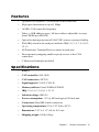
Features
•
Operates two separate CAN networks at the same time
•
High speed transmission up to I Mbps
•
16 MHz CAN controller frequency
•
Takes a 4 KB address space, 40 base address adjustable in steps
from C800H up to EFOOH
•
Optical isolation protection of 1000 VDC ensures system reliability
•
Wide IRQ selection for each port includes: IRQ3, 4, 5, 6, 7, 9, 10, 11,
12, 15
•
LED indicates Transmit/Receive status on each port
•
Direct memory mapping enables speedy access to the CAN
controllers
•
C library and examples included
Specifications
•
Ports: 2
•
CAN controller: SJA-1000
•
CAN transceiver: 82C250
•
Signal support: CAN-L, CAN-H
•
Memory address: From C800H to EFOOH
•
IRQ: 3, 4, 5, 6, 7, 9, 10, 11, 12, 15
•
Isolation voltage: 1000 VDC
•
Power consumption: +5 V @ 400 mA typical, 950 mA max.
•
Connectors: Dual DB-9 male connectors
•
Operating temperature: 32 to 1 22º F (0 to 50º C)
•
Dimensions: 7.25" x 4. 13" (18.4 x 10.5 cm)
•
Shipping weight: 0.9 lb (0.4 kg)
Chapter 1
General Information
3
4
PCL-841 Series User's Manual
CHAPTER
Hardware
Installation
2
Initial inspection
You should find the following items inside the shipping package (in
addition to this manual):
•
PCL-841 Dual-port CAN Interface Card
• C Driver and DataMonitor Utility Diskette
We have carefully inspected the PCL-841 mechanically and electricalIy before shipping. It should be free of marks and scratches and in
perfect working order upon receipt.
As you unpack the PCL-841, check it for signs of shipping damage
(damaged box, scratches, dents, etc.). If it is damaged or it fails to
meet specifications, notify our service department or your local
representative immediately. Also notify the carrier. Retain the shipping carton and packing material for inspection by the carrier. After
inspection we will make arrangements to repair or replace the unit.
When you handle the PCL-841, remove it from its protective packaging by grasping the rear metal panel. Keep the anti-vibration packing.
Whenever you remove the card from the PC, store it in this package
for protection.
Warning! Modern electronic devices are very sensitive to damage
from static electricity. Ground yourself before you touch the
card. We recommend that you ~use a grounded wrist strap
and place the card on a static dissipative mat wheneveryou
work with it. At the very least, touch the back of the
grounded chassis of the system unit (metal) before you
handle the board. Avoid contact with materials that hold a
static charge, such as styrofoam. Do not touch the exposed
circuit connectors.
6
PCL-841 Series User's Manual
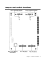
Jumper and switch locations
Chapter 2
Hardware Installation
7
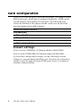
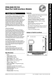
Card configuration
The PCL-841 has two ports, each with one jumper. The jumpers set the
IRQ for the ports, which can be configured separately. A DIP switch
sets the memory base address for each port. The following chart
shows the function of the jumper and the switch (see the previous
page for jumper and switch locations).
Switch and jumper functions
CAN controllers
JP1
Po rt 1
JP2
Port 2
Mennory base address
SW1 Port 1, Port 2
Default settings
Port I is set for COMI (IRQ=12, Memory address=DA00:0000).
Port 2 is set for COM2 (IRQ=IS, Memory address=DA00:0200). ;
If you need to change these settings, see the following sections.
Otherwise, you can simply install the card. Note that you will need to
disable your CPU card’s on-board COM ports, if any, or set them to
alternate addresses/IRQs.
8
PCL-841 Series User's Manual
Interrupt (IRQ) setup (JP1 and JP2)
Jumpers JPI and JP2 set the interrupts for Port I and Port 2, respectively. You can choose any IRQ from 3 to 15, except 8, 13 and 14.
When you choose IRQs, make sure they are not used for other cards
in the system. The following figures show the card’s default settings.
JP1: Port 1 IRQ Default
JP2: Port 2 IRQ Default
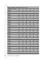
Memory base address (SW1)
The memory base address for the PCL-841, which requires 4 KB of
address space, is made up of the memory segment and its associated
offset. The address for the memory segment is set through SWI, a sixposition DIP switch. You can choose any base address from C800 to
EFOO. The following table shows the DIP switch settings and the
corresponding base addresses.
Memory address configUration (SW1)
Address/DIPswitch
C800H
C9OOH
CAOOH
CBOOH
CCOOH
CDOOH
CEOOH
CFOOH
A12
on
off
on
off
on
off
on
off
A13
on
on
off
off
on
on
off
off
A14
on
on
on
on
off
off
off
off
Chapter 2
A15
off
off
off
off
off
off
off
off
A16
on
on
on
on
on
on
on
on
A17
on
on
on
on
on
on
on
on
Hardware Installation
9
Mennory address configUration (SW1) cont'd
Address/DIP switch
A12
A13
A14
DOOOH
on
on
on
D100H
off
on
on
D200H
on
off
on
D300H
off
off
on
D400H
on
on
off
DSOOH
off
on
off
D600H
on
off
off
D700H
off
off
off
D800H
on
on
on
D9OOH
off
on
on
DAOOH
on
off
on
DBOOH
off
off
on
DCOOH
on
on
off
DDOOH
off
on
off
DEOOH
on
off
off
DFOOH
off
off
off
EOOOH
on
on
on
E100H
off
on
on
E200H
on
off
on
E300H
off
off
on
E400H
on
on
off
ESOOH
off
on
off
E600H
on
off
off
E700H
off
off
off
E800H
on
on
on
E9OOH
off
on
on
EAOOH
on
off
on
EBOOH
off
off
on
ECOOH
on
on
off
EDOOH
off
on
off
EEOOH
on
off
off
EFOOH
off
off
off
10
PCL-841 Series User's Manual
A15
on
on
on
on
on
on
on
on
off
off
off
off
off
off
off
off
on
on
on
on
on
on
on
on
off
off
off
off
off
off
off
off
A16
off
off
off
off
off
off
off
off
off
off
off
off
off
off
off
off
on
on
on
on
on
on
on
on
on
on
on
on
on
on
on
on
A17
on
on
on
on
on
on
on
on
on
on
on
on
on
on
on
on
off
off
off
off
off
off
off
off
off
off
off
off
off
off
off
off
Memory area
Once the memory segment for the base address is selected, the offset
will be automatically assigned for Port 1, Port 2, and hardware reset.
The following table shows the base addresses of the CAN controllers.
Base address (hex)
CAN controller
base:0000h
base:0100h
base:0200h
base:0300h
base:0400h
Basic- Port 1
HW reset Basic - Port 1
Basic- Port 2
HW reset Basic - Port 2
Not used
-
base:00FFh
base:01FFh
base:02FFh
base:03FFh
base:0FFFh
Chapter 2
Hardware Installation
11
12
PCL-841 Series User's Manual
CHAPTER
Software
Programming
3
Library functions
Quick reference table
The following table lists the available functions and their corresponding syntax and descriptions.
Liorary functions
Function
1
2
3
4
5
6
7
Syntax (in C)
caninitHW()
canExitHW()
canReset()
canConfig()
canNormalR~n()
canSendMsg()
canReceiveMsg()
Description
Sets IROs
Releases settings
Resets CAN port
Controls CAN port settings
Sets mode
Sends message
Reads data
Complete function description
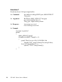
Function 1
Sets an IRQ number for Port I and Port 2.
14
Command
canluitHW (Ul segment, BYTE IRQ I, BYTE IRQ2)
Argument
UI segment, BYTE IRQI, BYTE IRQ2
segment=c000-df00 step 0x100
IRQI=Port I IRQ number 0 (polling),
3, 4, 5, 6, 7, 8, 9, 10, 1 1, 12, 14, 15
IRQ2=Port 2 IRQ number 0 (polling),
3, 4, 5, 6, 7, 8, 9, 10, 11, 12, 14, 15
0: polling
Response
l=successful
0=fail
PCL-841 Series User's Manual
Example
#include "can841.h"
main()
{
Ul gSegment=0xDA00;
BYTE CANl_IRQ, CAN2 IRQ;
CANI_IRQ=12;
CAN2_IRQ= 15;
if (canluitHW (gSegment, CANI_IRQ, CAN2_IRQ)==0)
printf ("HARDWARE INITIALIZATION ERROR!\n");
}
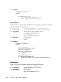
Function 2
Releases all seuings of the CAN card.
Command
canExitHW()
Argument
None
Response
l=successful
0=fail
Example
#include "can84 1.h"
main()
{
if (canExitHW()==0)
printf (“CAN RELEASE FAIL!\n”);
}
Function 3
Resets CAN port and flushes the TX/RX buffers.
Command
int canReset (BYTE port);
Argument
BYTE port;
port= port number (0 or 1)
Response
l=successful
0=fail
Chapter 3
Software Programming
15
Example
#include "can84 1 .h"
main()
{
if (canReset (0)==0)
printf ("RESET PORT I FAIL! n");
}
Function 4
Controls the setting of the CAN port’s acceptance code, acceptance
mask, and bus timing register.
Command
canConfig (BYTEport, CAN STRUCTcan);
Argument
BYTE port, CAN_STRUCT can;
port= port number (0 or 1)
can= CAN struct pointer
Response
l=successful
0=fail
Example
#include "canB4 1.h"
main()
{
CAN_STRUCT canl, can2;
can 1.acc_code=0;
can 1. acc_mask=0xff;
can 1.bt0=0;
can 1.bt I =0x 1 c;
if (canConfig(0,canl)==0)
printf ("CAN PORT I CONFIGURE ERROR!\n");
}
Function 5
Sets a CAN port to normal mode for normal operation.
16
Command
canNormalRun (BYTE port);
Argument
BYTE port;
port= port number (0 or 1)
PCL-841 Series User's Manual
Response
l=successful
0=fail
Example
#include "can84 1.h"
main()
{
if (canNormalRun(0)==0)
printf ("CAN Port I can’t change to Normal Mode!\n");
}
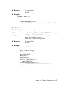
Function 6
Tells the CAN port to send a message.
Command
canSendMsg (BYTE port, MSG_STRUCT send msg);
Argument
BYTE port, MSG_STRUCT send_msg;
port= port number (O or 1)
send msg= send buffer pointer
Response
l=successful
0=fail
Example
#include “can84 1.h” main()
{
MSG_STRUCT smsg 1;
Ul i;
smsg 1.id=0x015;
smsg l.rtr=0;
smsg l.dlen=8;
for(i=0; i<smsg l.dlen; i++)
smsg l.data[i]=i;
if (canSendMsg(0,smsg 1)==l)
printf ("TRANSMISSION SUCCESSFUL!\n");
{
Chapter 3
Software Programming
17
Function 7
Read data from CAN port input buffer.
Command
int canReceiveMsg (BYTE port, MSG STRUCT
*msg ptr);
Argument
BYTEport, MSG_STRUCT *msg ptr;
port= port number (O or 1)
*msg_ptr= input buffer pointer
Response
l=message received
0=no message received
Example
#include "can841.h"
main()
{
MSG_STRUCT rmsg2;
if(canReceiveMSG, *rmsg2)==1)
{
printf ("Port2 receive: ID=%3X RTR=%ld
Length=%ld”, rmsg2.id rmsg2.rtr, rmsg2.dlen);
for (i=0; i<rmsg2.dlen; i++)
cprintf (" %2X", rmsg2.data[i]);
}
}
18
PCL-841 Series User's Manual
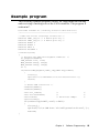
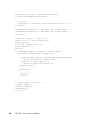
Example program
The following example program, can84 I.lib, implements the sending
and receiving of messages over the CAN controller. The program is
written in C.
#include "can841.h" /*Library function declaration*/
/*------------------------------------------------*/
/* CAN controller interrupt connection */
#define CAN1_IRQ 12 /* 0 means polling */
#define CAN2_IRQ 15 /* 0 means polling */
#define PORT1 0
#define PORT2 1
#define FAIL 0
#define SUCCESS 1
void main(void)
(
/* Declare the CAN card segment address. */
UI gSegment=OxDA00;
CAN_STRUCT canl, can2;
MSG_STRUCT smsql, smsg2;
MSG_STRUCT rmsql, rmsg2;
UI i;
if(canInitHW(gSegment,CANl_IRQ,CAN2 IRQ)==FAIL)
{
clrscr();
cprintf(“\n\n Hardware Initialization Error.’);
return;
}
/* Reset CAN controller */
canReset(PORT1);
canReset(PORT2);
canl.acc_code=0;
canl.acc mask=Oxff;
canl.btO=03;
canl.btl=0xlc;
/*
/*
/* baud rate lMbps
*/
*/
*/
if(canConfig(PORTl,canl)==FAIL)
{
clrscr();
cprintf("\n\n CAN Port %d Configuration Error",1);
return;
{
Chapter 3
Software Programming
19
memcpy(&can2, &canl, sizeof(CAN_STRUCT));
if(canConfig(PORT2,can2)==FAIL)
{
clrscr();
cprintf("\n\n CAN Port %d Configuration Error", 2);
return;
}
canNormalRun(PORTl); /* Put CAN1 into normal mode. */
canNormalRun(PORT2); /* Put CAN2 into normal mode. */
clrscr();
smsgl.id = 0x015; /* Set ID =8 */
smsql.rtr=l; /* Data lengths =8*/
smsgl.dlen=8;
for(i=0; i<smsql.dlen; i++)
smsgl.data[i] =i;
while(l)
{
canSendMsg(PORTl, smsgl); /* Send to CAN1 */
if(canReceiveMsg(PORT2, &rmsg2)==1)
{
cprintf("PORT2 receive:ID=%3X RTR=%ld Length=%ld",
rmsg2.id,rmsg2.rtr, rmsg2.dlen);
for(i=0; i< rmsg2.dlen; i++)
cprintf(" %2X",rmsg2.data[il);
printf("\n");
}
if (kbLit())
{
getch();
break;
}
}
/* Reset CAN controller. */
canReset(PORTl);
canReset(PORT2);
canExitHW();
clrscr();
}
20
PCL-841 Series User's Manual
CHAPTER
4
DataMonitor Utility
Software overview
The PCL-841 comes with a utility disk with the following software
capabilities:
•
•
•
CAN controller configuration
CAN transmission monitoring
Terminal emulation
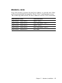
Main Menu
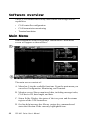
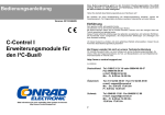
Run DataMonitor at the DOS prompt. DataMonitor’s main menu
screen will appear as shown below:
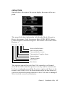
The main screen consists of:
A. Menu bar: Lists the available functions. From the main menu you
can select Configuration, Monitoring, and Terminal.
B. Monitor screen: Shows monitored data, including message index,
CAN device ID, data length, and data.
C. Status fields: Display the status of the two ports and the stanus
register of the CAN controllers.
D. On-line help/message bar: Shows various key commands and
states the function of the currently highlighted item.
22
PCL-841 Series User's Manual
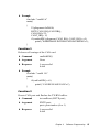
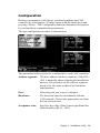
Configuration
Before you transmit a CAN object, you must configure the CAN
controller by selecting the <Config> menu with the cursor keys and
pressing <Enter>. The Configuration function determines the ports to
be used and their communication parameters.
The port configuration window is shown below.
The parameters below need to be configured for each CAN controller:
Address segment:
The base address (address segment) of the PCLj 841 is normally adjusted during the installation
process. The selection of the address segment
needs to be the same as that of the hardware
configuration.
Port:
Select the port you want to configure.
Baud rate:
The baud rate must be coordinated with the
CAN network. Choose the appropriate one from
the list of baud rates.
Acceptance code:
Specifies the value of the 8 most significant bits
of the identifier (ID 10 ... ID 3)
Chapter 4
DataMonitor Utility
23
Acceptance mask:
Specifies the bit positions which are "relevant",
for acceptance filtering.
Note: The acceptance code and acceptance mask are configured
through eight digits (I digit per bit) using 0 or 1.
Value
Definition
0
1
This bit position will accept only a’.relevantl message.
This bit position will not screen messages.
Example:
Acc Code = 11111111
AccMask= 11111111
The shown acceptance filter will accept every received message.
Interrupt:
Sets the interrupt for each port. Be sure that this
setting matches the IRQ already selected for the
PCL-841, which accepts values between IRQ3 to
IRQ15, except 8 and 13.
Running mode:
During the normal configuration and communication process, select Normal Mode. When the
system fails, you can hit <Enter> to reset the
CAN controller. Hit <Enter> again to return to
Normal Mode to further execute your configuration.
Monitor
Select the port to be monitored from the <Monitor> pull-down menu.
Press F3 to start and stop the monitoring process.
Monitor screen
The monitored data for a selected port appears in the monitor screen
(see area B in the diagram under Main Menu section.)
If the CAN controller is configured correctly and the transmission has
been successfully completed, every CAN object will be shown inorder
of appearance.
24
PCL-841 Series User's Manual
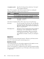
status Fields
Status fields at the right of the screen display the status of the two
ports:
The status fields show information including the Mode (Normal or
Reset), Acceptance Code, Acceptance Mask, BTR0, BTRI, Output
Control Register, and Status Register. The normal value of the Status
Register is:
0 0 0 0 1 1 0 0
Receive Buffer Status
Data Overrun Status
Transmit Buffer Access
Transmission Complete Status
Receive Status
Transmit Status
Error Status
Bus Status
The registers can only be read if the CAN controller is in Normal
mode. If the CAN controller operates correctly and the transmission
has been completed successfully, the status register will show as the
normal value: 00001100. If the Error Status and/or the Bus Status is 1,
you have selected the wrong baud rate or the CAN cable is damaged.
Also check the correct bus terminator.
Chapter 4
DataMonitor Utility
25
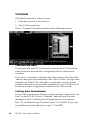
Terminal
This function provides a direct way to:
1. Send data over the CAN network.
2. Test CAN transmission.
Select <Terminal> from the menu bar for the following screen:
Transmitting data
To transmit data, the PCL-84 I must be connected to a CAN network
with at least one node and the configuration for the card must be
complete.
First, select <Terminal> to edit the data. Enter the port, the object ID
.and the data bytes as hexadecimal value. Press <Enter> to begin data
transmission. If the CAN controller is configured correctly and the
transmission has been successfully completed every CAN object will
be shown in order of appearance at the left side of the screen.
Testing data transmission
To test CAN transmission without actually sending, connect Port I to
Port 2 on the PCL-841. Select <Terminal> and enter port I as trans
mitting port. Port 2 will therefore be designated as receiving port.
Note: To send Data Frame (Transmit), enter “O” for RTR. If you want
to send Remote Frame (Request), enter "1" for RTR.
26
PCL-841 Series User's Manual
CHAPTER
Wiring
5
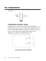
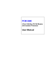
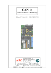
Pin assignments
The following figure shows the pin assignments for the card’s DB-9
connectors.
CAN
Termination resistor setup
Terminal resistors are factory installed to allow for impedence
matching. These resistors can be enabled by utilizing jumpers number
9 and 10 (shown below). Jumper 9 enables the terminal resistor for
port one, while jumper number 10 enables the terminal resistor for port
two. The value of the resistor should equal the characteristic
impedance of the signal wires (approximately 120 Q).
The following figure shows resistor placements.
28
PCL-841 Series User's Manual
CAN signal wiring
The CAN standard supports half-duplex communication. This means
that just two wires are used to transmit and receive data.
Wiring connections are as follows:
PCL-841 DTE (male DB=9)
Terminal DTE
Pin
7
3
2
Signal
CAN-H
GND
CAN-L
Signal
CAN-H
GND
CAN-L
Chapter 5
Wiring
29
30
PCL-841 Series User's Manual
APPENDIX
A
Register structure
This appendix gives a brief description of the CAN controller registers. For more detailed information, please refer to the Stand-alone
C~4N-eontmller Data Book from Philips Semiconductors Microcontroller Products. (You may also find the information on the enclosed
disk under the “Manual” directory, in the Word 6.0 file:
REGISTER.DOC.)
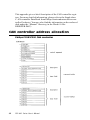
CAN controller address allocation
Philips PCX82C200 CAN controller
32
PCL-841 Series User's Manual
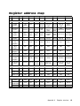
Register address map
#
TITLE
ADDR
7
6
5
4
3
2
1
0
Error
Interrupt
Enable
Transmit
Interrupt
Enable
Receive
Interrupt
Enable
Reset
Requset
Clear
Overrun
Status
Release
Abort
Transmission
Receive
Transmission Requset
Buffer
Control Segment
Control
Register
0
2
Command
Register
1
3
Stauts
Register
2
4
Interrupt
Register
3
5
Acceptance
Code
Register
4
AC.7
AC.6
6
Acceptance
Mask
Register
5
AM.7
7
Bus Timing
Register 1
6
SJW.1
8
Bus Timing
Register 0
7
SAM
9
Output
Control
Register
8
OCTP1
10
Test Register
(note 1)
9
Identifier
10
ID.10
ID.9
ID.8
ID.7
ID.6
ID.5
ID.4
ID.3
11
ID.2
ID.1
ID.0
RTR
DLC.3
DLC.2
DLC.1
DLC.0
Bytes 1-8
12-19
Data
Data
Data
Data
Data
Data
Data
Data
Identifier
20
ID.10
ID.9
ID.8
ID.7
ID.6
ID.5
ID.4
ID.3
RTR, Data
Length Code
21
ID.2
ID.1
ID.0
RTR
DLC.3
DLC.2
DLC.1
DLC.0
Bytes 1-8
22-29
Data
Data
Data
Data
Data
Data
Data
Data
RTR, Data
11
Length Code
12
Test
Mode
Overrun
Reserved Interrupt
Enable
1
Sync
Reserved Reserved Reserved
Bus
Status
Error
Status
Coto
Sleep
Transmission Transmit
Receive
Complete
Buffer Data Overrun
Buffer Status
Status
Access
Transmit
Status
Receive
Status
Reserved Reserved Reserved
Wake-Up
Interrupt
Overrun
Interrupt
Error
Interrupt
Transmit
Interrupt
Receive
Interrupt
AC.5
AC.4
AC.3
AC.2
AC.1
AC.0
AM.6
AM.5
AM.4
AM.3
AM.2
AM.1
AM.0
SJW.0
BRP.5
BRP.4
BRP.3
BRP.2
BRP.1
BRP.0
TSEG1.3
TSEG1.2
TSEG1.1
TSEG1.0
OCTN0
OCPOL0
OCMODE1
OCMODE0
TSEG2.2 TSEG2.1 TSEG2.0
OCTN1
OCPOL1
OCTP0
Map
Connect
Connect TX
Reserved Reserved Internal RX Buffer
Buffer CPU
Register 0 CPU
Access
Normal RAM Float Output
Internal
Conncet
Driver
Bus
Appendix A
Register structure
33
Register descriptions
Control Register (CR)
The Control Register is used to change the behavior of the
PCX82C200. Control bits may be set or reset by the attatched micro
controller, which uses the Control Register as a read write memory.
Command Register (CMR)
A command bit initiates an action within the transfer layer of the
PCX82C200. If a read access is performed to this address, the byte
11111111 (binary) is returned.
Status Register (SR)
The Status Register reflects the status of the PCX82C200 bus controller. The Status Register appears to the microcontroller as a read-only
memory.
Interrupt Register (IR)
The Interrupt Register allows identification of an interrupt source.
When one or more of this register’s bits are set, the INT pin is activated. All bits are reset by the PCX82C200 after this register is read by
the microcontroller. This register appears to the microcontoller as a
read-only memory.
Acceptance Code Register (ACR)
The Acceptance Code Register is part of the acceptance filter of the
PCX82C200. This register can be accessed (read write) if the Reset
Request bit is set HIGH (present). When a message which passes the
acceptance test is received and if there is an empty Receive Buffer,
then the respective Descriptor and Data Field are sequentially stored
in ~1:} this empty buffer. In the case that there is no empty Receive
Buffer, the Data Overrun bit is set HIGH (overrun).
34
PCL-841 Series User's Manual
Acceptance Mask Register (AMR)
The Acceptance Mask Register is part of the acceptance filter of the
PCX82C200. This register can be accessed (read write) if the Reset
Request bit is set HIGH (present). The Acceptance Mask Register
classifies the corresponding bits of the acceptance code as “relevant”
or “don’t care” for acceptance filtering.
Bus Timing Register O (BTRO)
The Bus Timing Register O defines the values of the Baud Rate
Prescaler (BRP) and the Synchronization Jump Width (SJW). This
register can be accessed (read write) if the Reset Request bit is set
HIGH (present).
Bus Timing Register 1 (BTR1)
The Bus Timing Register I defines the length of the bit period the
location of the sample point, and the number of samples to be taken at
each sample point. This register can be accessed (read write) if the
Reset Request bit is set HIGH (present).
Output Control Register (OCR)
The Output Control Register allows, under software control, the setup
of different driver configurations. This register may be accessed (read
write) if the Reset Request bit is set HIGH (present).
Test Register (TR)
The Test Register is used only for production testing.
Transmit Buffer
The Transmit Buffer stores a message from the microcontroller to be
transmiued by the PCX82C200. It is subdivided into the Descriptor
and Data Field. The Transmit Buffer can be wrinen to and read from
by the microcontroller.
Receive Buffer
The layout of the Receive Buffer and the individual bytes correspond
to the definitions given for the Transmit Buffer layout, except that the
addresses start at 20 instead of 10.
Appendix A
Register structure
35
36
PCL-841 Series User's Manual