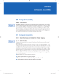
1
SECTION 2
INSTALLATION
7) Add the “Alarm Reset” output. This signal should be “on” as long
as the system reset push-button is depressed.
________________________________________________________
2.8 HSL-WI3 SET-UP
The HSL-WI3 is shipped from the factory with the PLC program
“HSLWI3” loaded in the PLC section of the HSL-WI3 module and
the PLS channel set-point file “WI7TMG” loaded in the PLS section.
In most cases, the following user variables and timing channels may
have to be altered to tune the HSL-WI3 to the actual bodymaker it is
controlling.
Once the HSL-WI3 is installed and the control system is powered
back up, perform the following to set-up and tune the HSL-WI3. The
set-up is performed using the Display/Keypad of the HSL-WI3 or a
PC running the “HSLWI3” set-up program. See section 3 for a
description of the Keypad commands and menu displays of the HSLWI3 Display/Keypad. See section 4 for a description of the menus,
variables and how to use the Windows based set-up program. See
section 5 for a description of the menus, variables and how to use the
DOS based set-up program.
________________________________________________________
2.8.1 DEFAULT SET-UP VARIABLES
As shipped, the user variables for the HSL-WI3 are set to the
following defaults:
Brake Wear Compensation:
Enabled
Desired BDC Stop Position (Low Speed)
Desired BDC Stop Position (High Speed)
: N
: 000
: 000
Maximum Allowed Stopping Response (degrees)
: 300
Bodymaker Running Speeds:
Low Speed (SPM)
High Speed (SPM)
: 250
: 350
Trimmer Speed Reference:
Maximum Speed
Idle Speed (W/I stopped)
High Speed Offset
: 375
: 250
: 20
HSL-WI3 User’s Manual
SYSTEMS Electronics Group
- 19 -
SECTION 2
INSTALLATION
The “WI7TMG” timing channel file, as shipped, contains the
following default timing set-points:
CHAN
ON - OFF
DESCRIPTION
CH00:
CH01:
CH02:
CH03:
CH04:
CH05:
CH06:
CH07:
CH10:
CH11:
CH12:
CH13:
CH14:
CH15:
CH16:
CH17:
150
180
155
110
230
150
120
180
000
___
___
___
___
___
___
___
BDC (high) Timing
BDC (low) Timing
Short Can Check Timing
Sensor Check Timing
Cupfeed Timing
Air Strip (low) Timing
Air Strip (high) Timing
PLC Clock Timing
Motion (“on” for 30, “off” for 30 thru-out)
spare
spare
spare
spare
spare
spare
spare
-
170
200
175
130
300
200
190
000
030
___
___
___
___
___
___
___
________________________________________________________
2.8.2 SET BODYMAKER SET-UP PARAMETERS
The Bodymaker set-up parameters include: enabling or disabling the
brake wear compensation, setting the desired low and high speed
stopping points (if the brake wear compensation is enabled), setting
the maximum allowed stopping response, and setting the bodymaker
running low and high speeds.
Brake Wear Compensation: If the brake wear compensation is to
be used, enable it by setting the “Brake Wear Compensation Enable”
to “Y”. Set the “Desired BDC Stop Position (Low)” and “(High)” as
well if the compensation is enabled. The “Desired BDC Stop
positions” are the location you want the ram to be at when it comes to
rest after a BDC stop. Both the “Low” and “High” desired stopping
positions are generally set to 000 degrees. Enabling the brake wear
compensation allows the HSL-WI3 to automatically adjust the BDC
timing channels (CH00-High) and (CH01-Low) as necessary such
that the press will stop at the desired stopping position regardless of
the actual brake response.
HSL-WI3 User’s Manual
SYSTEMS Electronics Group
- 20 -
SECTION 2
INSTALLATION
If the brake wear compensation is not to be used, disable it by setting
the “Brake Wear Compensation Enable” to “N”. Disabling the brake
wear compensation requires the BDC (High) timing (CH00) and the
BDC (Low) timing (CH01) signals to be set manually such that the
press stops at BDC.
Note: If the brake response then changes, the press will not stop at
the desired position if the brake wear compensation is disabled.
Maximum Allowed Stopping Response: This parameter defines
what the maximum allowed brake response is before the “Brake
Response Too Long” alarm is generated. If the actual brake response
(number of degrees from when the brake is activated to the position
where the press ends up at rest) when a BDC stop is performed is
longer than this number, the alarm is generated. If the actual brake
response is less, the alarm is not generated. Set this parameter to the
value where the brake response is considered too long and service to
the brake should be performed (typically 270 to 300 degrees).
Bodymaker Running Speeds: Set the Bodymaker running “Low
Speed” and “High Speed” to the speeds that the bodymaker will
actually run at when the respective speed is selected.
Note: This is not a speed reference that will make the bodymaker run
at the speeds entered but is instead simply parameters used by the
HSL-WI3 to know when to switch between the BDC (Low) and BDC
(High) timing as well as the Air Strip (Low) and (High) timing etc.
See section 3.4 (HSL-WI3 Keypad/Display) or section 4 (Windows
based set-up program) or section 5 (DOS based set-up program) for
details on setting the above set-up parameters.
HSL-WI3 User’s Manual
SYSTEMS Electronics Group
- 21 -
SECTION 2
INSTALLATION
________________________________________________________
2.8.3 SET TRIMMER SPEED REFERENCES
Set the “Trimmer Maximum Speed”, “Trimmer Idle Speed”, and
“Trimmer High Speed Offset” as desired. These three parameters are
used to actually control the speed of the trimmer (via the 0-10VDC
trimmer speed reference output of the HSL-WI3 module).
Trimmer Maximum Speed: The “Trimmer Maximum Speed”
parameter is used to scale the 0-10VDC analog output such that when
the bodymaker is running at the speed entered in “Trimmer Maximum
Speed”, the analog output will be at 10 volts.
Trimmer Idle (Minimum) Speed: This parameter determines the
speed the trimmer will run at when the bodymaker is stopped (declutched).
Note: When the bodymaker is running, the trimmer speed reference
is proportional (as set by the “Trimmer Maximum Speed” scaling) to
the speed of the bodymaker. This parameter is used to provide the
speed reference when the bodymaker speed is zero.
Trimmer High Speed Offset: This parameter is used to modulate
the speed of the trimmer as a function of cans present at the infeed of
the trimmer. A high infeed sensor can be added to the trimmer infeed
such that the trimmer will run at the bodymaker running speed plus
the “Trimmer High Speed Offset” value. This allows the trimmer to
speed up when the infeed to the trimmer backs-up and slow down
once the trimmer runs the cans out.
See section 3.4 (HSL-WI3 Keypad/Display) or section 4 (Windows
based set-up program) or section 5 (DOS based set-up program) for
details on setting the above set-up parameters.
________________________________________________________
2.8.4 SET MACHINE ZERO
Inch the bodymaker to back dead center (BDC) and set the HSL-WI3
resolver offset per section 3.4 (HSL-WI3 keypad) or section 4
(Windows based set-up program) or section 5 (DOS based set-up
program).
HSL-WI3 User’s Manual
SYSTEMS Electronics Group
- 22 -
SECTION 2
INSTALLATION
________________________________________________________
2.8.5 VERIFY LOCATION OF SHORT CAN TIMING (CH02)
By inching the machine, verify that the “Short Can” timing (CH02) of
the HSL-WI3 first turns “on” when the short can sensor is over the
nose of the punch on the forward portion of the stroke (see figure 2).
This would be where the sensor would first “see” the can as it
emerges from the die set. Verify that the “Short Can” timing turns
“off” right before the sensor would quit seeing the lip of the can as the
ram continues it's forward motion. Adjust either or both of the turn
“on” or turn “off” locations of CH02 until the above is achieved.
Depending on the location of the short can sensor, CH02 is typically
set “on” at 155 degrees and then back “off” at 175 degrees.
________________________________________________________________________________
Figure 2 - Short Can Check Timing Sequence
HSL-WI3 User’s Manual
SYSTEMS Electronics Group
- 23 -
SECTION 2
INSTALLATION
Note: The short can sensor must “see” can the entire time the
“Short Can” timing (CH02) is “on” in order to pass the short can
check. Otherwise, the “Short Can” alarm will be generated.
At this time, also verify that the “Sensor Check” timing (CH03) is
also set correctly. This timing signal should go “on” for 20 degrees
then back “off” just prior to the punch emerging from the die set
(typically 110 to 130 degrees). This signal is used to verify that the
short can sensor has not failed “on” and therefore the short can sensor
must be “off” the entire time CH03 is “on” otherwise the “Die Sensor
Fail” alarm is generated.
See section 3.4 (HSL-WI3 Keypad/Display) or section 4 (Windows
Based set-up program) or section 5 (DOS Based set-up program) for
details on setting CH02 and CH03.
________________________________________________________
2.8.6 VERIFY MACHINE OPERATION
Once steps 2.8.2 thru 2.8.5 are complete, run the machine in normal
production (both at low and high speeds where practical) and verify
the following:
Verify Air Strip Timing: With the machine running, with the
cupfeed open, verify that the cans are stripped with-out any problems
and that no blow-outs are occurring (verify at both low and high
speed if a problem is occurring, adjust the respective “Air Strip”
timing (CH05-Low Speed, CH06-High Speed) until the problem is
corrected. See section 3.4 (HSL-WI3 Keypad/Display) or section 4
(Windows based set-up program) or section 5 (DOS based set-up
program) for details on adjusting CH05 and CH06.
Verify Short Can Timing: With the machine running with the
cupfeed open, verify that no false short can faults are occurring (short
can alarm occurs when full length can is made). If false short can
alarms are occurring, narrow the short can timing one degree at a time
until the false short can alarms quit occurring.
HSL-WI3 User’s Manual
SYSTEMS Electronics Group
- 24 -
SECTION 2
INSTALLATION
Verify that the short can detection is working correctly by generating
a short can and verifying that the short can alarm is generated for this
can. This can be done by stopping the press, removing one of the die
rings then punching a cup in single stroke mode with the die ring
removed. The short can alarm should be generated when the first cup
is punched.
Verify BDC Stops: If the brake wear compensation is enabled,
verify that the press does stop at the desired location in both the high
and the low speeds.
Note: When the HSL-WI3 is first installed, it will take a few
successive stops for the algorithm to program the BDC timing
channels to the correct position. The compensation is enabled after
the press has been running at a fixed speed in continuous. The BDC
timing channels will not be modified when single strokes are made or
if press is started in continuous and then immediately stopped again.
Wait about 5 seconds after the press is started before performing the
BDC stop to verify the stop position.
If the brake wear compensation is disabled, manually adjust both the
BDC (High) timing (CH00) and the BDC (Low) timing (CH01) such
that the press stops at back dead center at both respective speeds. See
section 3.4 (HSL-WI3 Keypad/Display) or section 4 (Windows based
set-up program) or section 5 (DOS based set-up program) for details
on adjusting CH00 and CH01.
The Machine Is Now Set-Up and Ready To Run.
HSL-WI3 User’s Manual
SYSTEMS Electronics Group
- 25 -