1
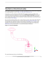
Tetra Mesh in a Piston/Valve Assembly
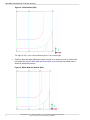
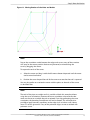
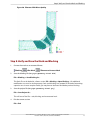
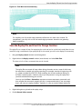
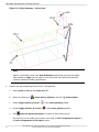
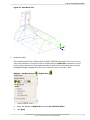
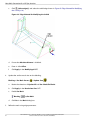
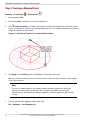
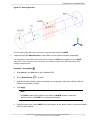
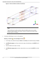
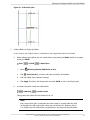
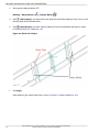
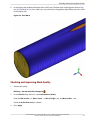
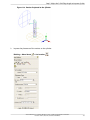
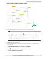
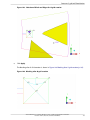
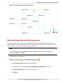
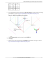
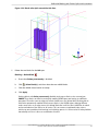
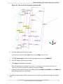
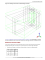
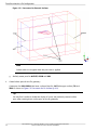
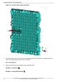
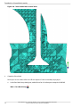
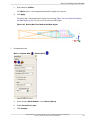
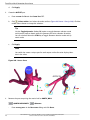
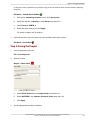
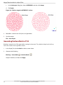
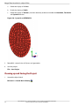
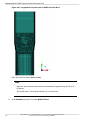
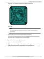
Figure 186: Region between PORT and STEM for Thin cut
Figure 186: Region between PORT and STEM for Thin cut (p. 240) shows a close-up view of the region
between the PORT and STEM parts where the Thin cut will be applied, respecting the two surfaces.
3.
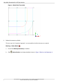
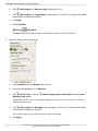
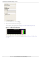
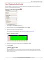
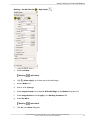
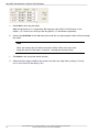
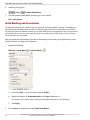
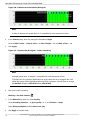
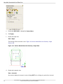
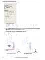
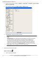
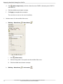
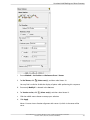
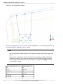
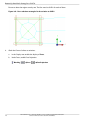
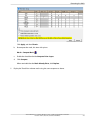
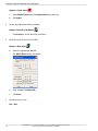
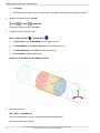
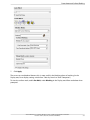
Specify Surface Mesh parameters.
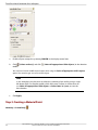
Mesh > Surface Mesh Setup
a.
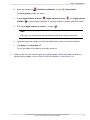
Click
(Select surface(s)).
b.
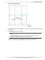
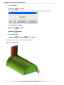
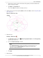
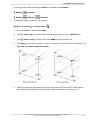
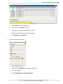
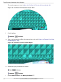
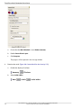
With the mouse in the display area, press a to select all surfaces.
c.
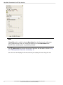
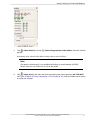
For Maximum Size, enter a value of 16.
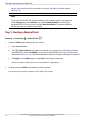
Note
Setting the maximum size on the surfaces will not affect “Curvature/Proximity Based
Refinement” set in an earlier step.
d.
4.
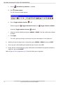
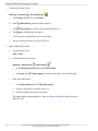
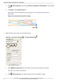
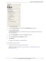
Click Apply.
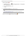
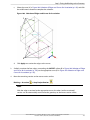
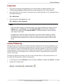
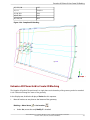
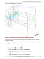
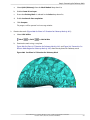
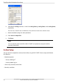
Save the project.
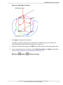
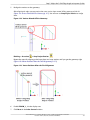
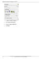
File > Save Project
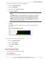
Mesh parameters will be saved along with the geometry in the tetin file.
240
ANSYS ICEM CFD 14.5 - © SAS IP, Inc. All rights reserved. - Contains proprietary and confidential information of ANSYS, Inc. and its subsidiaries and affiliates.