1
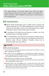
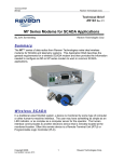
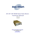
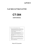
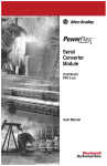
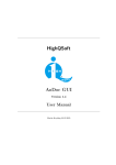
Technical Brief
AN165 Rev A1
2320 Cousteau Court
1-760-444-5995
[email protected] | www.raveon.com
GPS Tracking Off-Road
By John Sonnenberg
Raveon Technologies Corp
Overview
The M7 GX series of GPS transponders are excellent for real-time tracking of vehicles. They
work in remote areas and have a very fast update rate. By installing a Raveon GPS
transponder in an off-road race vehicle (buggy, truck, motorcycle, UTV, or quad) race teams
and support personnel have an exciting new way of watching the race and the race-vehicle can
quickly locate its support personnel.
The system operates as follows:
1. The M7 radios in the system must be programmed to a valid VHF or UHF radio frequency.
Raveon has both VHF and UHF versions of its M7 GPS transponder.
2. Each vehicle is assigned a unique ID number (1-9999). The ID number is programmed into the
M7 radio.
3. The TDMA time and the time-slots for each M7 radio must be configured. The TDMATIME is
how often the radio transmits its position. The SLOTNUM is the unique slot number each radio
will transmit in. Slot numbers start with 1 and are sequentially numbered.
4. The M7 GX GPS transponders are installed in race and support vehicles. They will periodically
transmit its GPS position out using its built-in VHF or UHF 5 watts radio.
5. Besides transmitting GPS position, the M7 GX can also receive the GPS position from other
vehicles. As long as the GPS transponder is within radio range of another vehicle, it will output a
message via its RS232 serial port whenever it hears the GPS position of another vehicle.
6. The M7 GX GPS transponder has an internal GPS receiver and a VHF or UHF radio transceiver.
Out of its RS232 serial port, the M7 will periodically output the local GPS location using standard
NMEA messages (GGA, GLL, RMC…)
7. Optionally, in any vehicle, the M7 GX GPS transponder may be wired to a GPS display in the
vehicle. When connected to a suitable display, the M7 will send a message to the display telling
it to put an icon at the location of any vehicle it receives that report its GPS position.
8. If you want to track using a PC, simply load RavTrack PC into a laptop, desktop, or notebook,
and connect it to another M7 G GPS transponder. Raveon sells RavTrack PC for dispatch and
AVL applications, but it makes a nice in-vehicle display or data logger for post-race replay of an
event.
Things to consider
A. The M7 GX uses licensed UHF and VHF radio channels. Unless you are
operating on a VHF MURS radio channel, you will need to obtain an FCC
license to use this product.
B. The GPS tracking range is limited to the radio range of the 5-watt radio
transceiver built into the M7.
The M7 GX series of GPS transponders may be directly connected to a Lowrance
Globalmap 480, 540C, 7200 or a Globalmap 840C navigation display. Various
Garmin hand-held GPS receivers also work with the M7. Most GPS receivers that
support RS232 serial NMEA message input will work with the M7, but some will not.
Contact Raveon for details on which models work, or try it out and see.
When connected to da GPS display, the display map will show the location of the
vehicle it is in PLUS the location of all other M7 transponders within radio range. This
unique feature allows a person to quickly, easily, and inexpensively, make a mobile
AVL system for tracking cars, trucks, racecars, or construction equipment.
The GPS display must have an interfaces for a “NMEA 0183″ devices, which is
another way of saying that they can connect to other devices using a serial cable.
The NMEA 0183 is an RS232 serial connection that typically operates at 4800 baud.
It is used to exchange waypoint and other information between displays, GPS devices,
and transponders.
When Raveon’s M7 GX transponder is connected to a GPS display using the NMEA
0183 connection, the M7 transponder can put icons on the screen of the display. As
the transponder received updated positions from other vehicles, it updates the position
of the icons on the Lowrance display. It does this by sending a “GPWPL” message to
the display. The display interprets the message as a waypoint location, and puts a
waypoint at the specified location on the map, with the ID number of the vehicle that is
at that location.
This type of Automatic Vehicle Location (AVL) technology must be installed and
maintained by qualified service personnel. If you or your team do not have the
technical skills required, contract with a two-way radio service shop or similar type
company to install and maintain your system.
The M7 GX GPS Transponder
The M7 GX GPS transponder is available in two forms; the Standard and the
Weatherproof versions.
Standard M7 GX
Weatherproof M7 GX WX
If the unit will be in a location where it will get wet or washed, the weatherproof version
should be used.
The technical documentation for Raveon’s GPS tracking products is located at:
http://ravtrack.com/Downloads.html
The Technical Manual for the GPS transponder is located here:
http://ravtrack.com/pdf_manuals/RV-M7-GX_Tech_Manual.pdf
Raveon highly suggest you familiarize yourself with the product, read the manuals, as
well as read and heed all safety warnings before proceeding.
Plan Your System
Because the M7 usually must be removed from the vehicle to reprogram it, it is
important that you plan your system correctly and configure the M7s as planned. To
facilitate this, Raveon has a Windows program called RadioManager that gives the
user a graphical interface to program the radio. Or, you can use any terminal program
such as HyperTermina.
A free download of RadioManager is available here: http://ravtrack.com/RadioManager-Download.html
You must configure a number of paramters and the system frequency. Your GPS
position transmission rate, radio IDs, and a number of other settings must be preconfigured for your system to operate properly. Read the Technical Manual for
information on how to configure your system and program your M7 radios.
Record your system configuration in a table or spreadsheet like the one on the
following page.
Raveon M7 GX GPS Transponder System Configuration Worksheet
General System Configuration Information
Your Value
Frequency in MHz
M7 Parameter Name
ATFX
Transmit Rate
TXRATE
TDMA time epoch.
TDMATIME
Typically this is the same time as
the Transmit rate.
Slot Time
SLOTTIME
This is the time in milliseconds each
vehicle has to transmit
Note: To set the vehicle-specific parameters use
the following commands:
Vehicle
ID
Slot
Number
GPS
Mode
Address
Mask
ID to send
TO
ID
ATMY xxxx where xxxx is the ID
Slot Number
SLOTNUM xxx where
xxx is the slot number
Mode
GPS x where x is the desired
GPS mode. Use GPS 4 for
vehicles, vehicles with a GPS
display, and GPS 2 when using
a PC with RavTrack PC software
to display.
To ID
TOID xxxx where xxxx is the ID
to transmit the GPS position to.
Mask
ATMK xxxx where xxxx is the
address mask. Set to 0000 to
receive everything from
everyone.
Setup and Initial Configuration
Before the M7 is installed in the vehicle, it must first be programmed. From the
factory, they are configured to work, so all you will need to do is configure them for
your operation.
You must read the M7 GX Technical Manual to properly configure the M7.
Here is a summary of the steps you must perform.
1. Connect a DC power source to the DC IN connection on the front of the
modem.
2. Connect a computer terminal, or PC computer running HyperTerminal, to the 9pin I/O connector. The factory default serial ports settings are 4800 bps, 8 data
bits, 1 stop, no parity. Note, the serial port may be 38400bps if the RV-M7 GX
is in GPS modes 2 or 3.
3. Put the RV-M7 GX into the command mode. (enter +++ per Section Error!
Reference source not found.)
4. Program the modem’s operating frequency to your desired operating
frequency. This is done with the ATFX xxx.xxxxx command. See the Section
Error! Reference source not found. for information describing the various
parameters that may be modified in the modem. In most applications, the
default settings from the factory will work fine.
Note: The MURS version of the M7 (RV-M7-VM), the unit is pre-set to the 5
MURS channels on channels 1-5. The user cannot change the frequency of
the M7, only the channel number. Use ATHP x to select the MURS radio
chanel.
5. With the unit in the command mode, change any of the default operating
parameters that must be modified. From the factory, the modems are
configured and delivered ready-to-use. Out of the box, they will communicate
on the default radio channel using the factory defaults. Raveon highly
recommends you test them first with the factory defaults and see how they
work before reprogramming them. In general, the parameters you may want to
modify will be:
ATFX
GPS x
Frequency for this channel. Set to your frequency.
Set the operating mode of this unit. See Section Error! Reference
source not found. for a list of the various modes.
ATMY
The individual ID of this unit. Default is 0001. Number all of your RVM7 GX transponders with a different MYID. Raveon recommends
sequentially numbering them, starting at number 1.
ATDT
The address of the unit this modem will talk to. Default is 0001.
ATMK
The network address mask. Default is F000. This means this unit will
receive all transmissions from any other unit with an ID beginning with
0 (0001 thru 0999).
KEYPHRASE Enter a security key code. Use any word or phrase 1-16
characters long. It is case-sensitive. DO NOT FORGET WHAT
YOU SET IT TO! The KEYPHRASE is the only parameter that
cannot be read out of the RV-M7 GX. It must be the same as the
KEYPHRASE programmed into all the other RV-M7 GX
transponders in your system. The factory default KEYPHRASE is
RAVEON, call capitals.
SLOTNUM
This will change the TDMA slot assignment, leaving the ID (MYID)
unchanged. Typically, the ID and the slot number are the same.
Once this command is used, the TDMA slot number for this
transceiver to will not change if the ID of the device is changed.
Set SLOTNUM to -1 to force the Slot Number to be automatically
set to the MYID of the radio. This is the factory default setting.
The radio is now ready to install and use. Remember, that from the factory, all RV-M7
GX modems are configured to simply work. Plug in power and connect to the serial
port at 4800 baud, and the modems will communicate on the default channel.
What you will see come out of the serial port with the factory default settings (GPS 4
mode), is a $GPWPL… message, every time one RV-M7 GX in your system
transmits.
The RV-M7-VM MURS version of the M7 has five user selectable channels. The
channel is selected with the ATHP command. The RV-M7-VM modem is factory-set
to these five channels, and the modem cannot be programmed to operate on any
frequency other than these five.
1
2
3
4
5
151.820 MHz
151.880 MHz
151.940 MHz
154.570 MHz
154.600 MHz
M7 GX Installation in the Vehicle
You will need to connect at least 3 things to the M7 GPS transponder and maybe a
fourth. They are:
A. DC Power (10-16V DC)
B. Radio antenna. UHF or VHF depending upon the band you use.
C. GPS antenna.
D. Optional display. (Lowrance, PC, Garmin…)
To install a GPS transponder in a vehicle, follow these steps:
1.
Secure the RV-M7 modem using the mounting holes on the side flanges of
the unit. You might want to locate it so that the front panel LEDs are visible.
2.
Connect a DC power source to the DC IN connection on the front of the
modem. Use the supplied cable, or 18AWG wire, and connect the RED
wire to +, and the black wire to – (ground). The black wire and the case of
the RV-M7 should be connected to earth ground.
3.
Connect a good quality antenna, tuned to the operating frequency, to the
RF connector on the front of the modem. Use a good antenna, and mount it
is at as high-above obstructions as possible. On the roof is the best.
Avoid using magnet-mount antennas for race vehicles. They may be OK for
a chase vehicle if the driving and terrain is not too rough.
4.
Connect a GPS antenna to the SMA connector of the RV-M7 GX. Although
a passive antenna may work if the cable length is very short, it is
recommended that an amplified antenna be used, rated at 3.3V operation.
Mount the GPS antenna so it can see the sky. On the roof of the vehicle is
best. You may have to experiment with locations to find one that is easy to
mount the antenna to and can also see the sky. There are two popular
mounting methods: thru-hole and magnet-mount. If you use a magnet-
mount GPS antenna, we recommend you also zip-tie it to the vehicle.
5.
Wire the GPS display or computer, terminal, controller, or other hardware
device that will be using the RV-M7 to its DB-9 serial I/O connector using a
shielded cable. Secure it to the RV-M7 with the two mounting screws on the
sides of the DB-9 connector. For a tracking-only application, nothing needs
to be wired to the DB9 connector of the M7. Only if you have an in-vehicle
display do you connect to the DB9. The following section describes how to
wire in a Lowrance to the M7, but most other displays will be similar. More
GPS display information is on Raveon’s web site here:
http://ravtrack.com/GPStracking/category/installation/
Lowrance 480, 540C, 7200 and 840C Wiring
From the Lowrance technical manual, here is how their NMEA 0183 interface works:
NMEA 0183 Cable Connections
NMEA 0183 is a standard communications format for marine electronic equipment. For
example, an autopilot can connect to the NMEA interface on the GlobalMap 540c and receive
positioning information. The GlobalMap 540c can exchange information with any device that
transmits or receives NMEA 0183 data. See the following diagram for general wiring
connections. Read your other product’s owner’s manual for more wiring information.
Below is the cable diagram from the Lowrance user manual for the data cable. Often,
installers will cut-off the data cable wires, making the connection to the cable a
challenge.
NMEA 0183 Wiring (Data cable)
To exchange NMEA 0183 data, the GlobalMap 540c has one NMEA 0183 version 2.0
communication ports. Com port one (Com-1) can be used to receive NMEA format GPS data.
The com port can also transmit NMEA format GPS data to another device. The four wires for
the com port are combined with the Power Supply cable and NMEA 2000 Power cable to form
the power/data cable (shown earlier). Com-1 uses the yellow wire to transmit, the orange wire
to receive and the shield wire for signal ground. Your unit does not use the blue
wire.
The M7 DB9 Serial Connector
The 9-pin serial I/O connector to the M7 is a female 9-p D-subminiature connector
having the following pins configuration.
Front-view of DB-9 connector on modem (female)
Pin #
Name
Dir
Function
1
2
3
4
CD
RxD
TxD
DTR
out
out
in
in
5
GND
6
7
8
DSR
RTS
CTS
9
Power
Carrier detect
Receive data
Transmit data
Data terminal
ready
Ground
connection
Data Set Ready
Request to send
Clear to send
DC power (not
Ring signal)
out
in
out
In/out
Level / Specification
Data out of the modem.
Data into the modem.
Normally ignored by the FireLine modem.
Signal and power ground
User may supply the DC power to the
modem on this pin.
Wiring the DB9
The Lawrence’s “Data Cable” must be connected to the M7 transponder. This
connection will allow the M7 to put icons on the screen of the Lowrance display,
showing the location of other tracked vehicles. The Raveon M7 GPS transponder
uses a 9-pin “DB9″ connector to connect to the Lowrance. Solder the Lowrance data
cable wires onto a DB9 connector and plug the DB9 into the M7 transponder as
shown below:
The orange wire goes to pin two of the DB9, the yellow wire to pin 3, and the shield
braid of he cable connects to pin 5 of the DB9. The blue wire is trimmed off.
The extra wires on the Lowrance display called NMEA 2000 power are typically not
used in a vehicle installation, and may be wrapped up with electrical tape and tucked
away.
Configuring the Lowrance
Set the NMEA communication of the Lowrance to 4800 baud. System Setup >
Communications Port. Enable NMEA 0183 input and set the baud to 4800.
Configuring the M7 GX Transponder
Raveon has a designed the M7 GX transponder to work with Lowrance Display or any
other NMEA 0183 display that can accept the “$GPWPL” NMEA message. The
$GPWPL is an industry standard message that the Lowrance displays and many other
GPS displays interpret as a waypoint command. The M7 GX outputs this $GPWPL
message to put icons on the screen of the Lowrance, and to move the icons around
on its screen.
To configure the M7 transponder to output the $GPWPL message, set the M7 GX to
GPS mode 2. To do this, put it into the configuration mode by send the +++ into the
serial port. The M7 will respond with an OK. Type GPS 4 and press enter to put it
into GPS 4 mode. GPS 4 is the mode that causes the M7 GX to output $GPWPL
messages whenever it receives a status/position message over the air.
How Far Can I track my Vehicle?
A quick answer: About as far as a standard voice radio will allow you to talk.
In flat wide-open areas, such as deserts, grasslands, and farms, vehicle-to-vehicle
communications will be 2 miles on the low end and often as much as 10 miles on the
high end. A base-station, either with a 15-meter tower or placed on a local hill, will
reliably communicate out to 10 miles, and often out to 20-30 miles.
In a rolling hills area, such as much of Nevada, Wisconsin, or Baja Mexico, vehicle-tovehicle range will be 1-2 miles as long as both vehicles are not in a valley. The range
will often go up to 15+ miles as both vehicles crest hills. A base-station, either with a
15-meter tower or placed on a local hill, will reliably communicate out to 7 miles, and
often out to 20-40 miles.
In mountainous areas or wooded hills, such as much of Colorado, Tennessee, and
northern California, vehicle-to-vehicle range will be ½ - 5 miles and will also be very
sporadic depending on the terrain between the vehicles. The M7 GX takes advantage
of this by frequently reporting its position, so that as vehicles crest peaks, they can
receive location transmissions from a long way away. Often the vehicle-to-vehicle
range will be as far as 15+ miles as the vehicles both crest hills. A base-station placed
on a mountain top can extend reliable communicate out to 10+ miles, and often out to
as much as 50 miles.
In urban areas and cities, structures will create multi-path and interference, reducing
the usable range. Communications will be very similar to operation in rolling hills.
Vehicle-to-vehicle range will be 1-3 miles. A base-station either with a 15-meter tower
or placed on a local hill, will reliably communicate out to 5-7 miles, and often out to 10
miles.
Raveon Technologies Corporation
990 Park Center Drive, C
Vista, CA 92081
[email protected]
760-727-8004