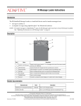
1
Director™ Sign User Manual (pn 9702-2005A)
4/15/2002
Director™ Sign User Manual
The most recent update of this manual can be found at Adaptive’s Web site: http://www.adaptivedisplays.com
Manual part number: 9702-2005A
Revision date: 4/15/2002
1
Director™ Sign User Manual (pn 9702-2005A)
4/15/2002
NOTE: Due to continuing product innovation, specifications in this manual are subject to change
without notice.
© Copyright 2002 Adaptive Micro Systems, Inc. All rights reserved.
Adaptive Micro Systems
7840 North 86th Street
Milwaukee, WI 53224 USA
414-357-2020
414-357-2029 (fax)
http://www.adaptivedisplays.com
The following are trademarks of Adaptive Micro Systems: Adaptive, Alpha, AlphaNet plus,
AlphaNET 2.0, AlphaEclipse, AlphaPremiere, AlphaTicker, AlphaVision, AlphaVision InfoTracker,
Automode, BetaBrite, BetaBrite Director, BetaBrite Messaging Software, Big Dot, PPD, Smart Alec, Solar,
TimeNet.
The distinctive trade dress of this product is a trademark claimed by Adaptive Micro Systems, Inc.
2
Director™ Sign User Manual (pn 9702-2005A)
4/15/2002
Contents
1
Introduction.......................................................................... 6
Purpose ......................................................................................................................................................6
Revision history..........................................................................................................................................6
Related documentation...............................................................................................................................6
Controlling electrostatic discharge (ESD) ...................................................................................................7
Safety information ......................................................................................................................................7
Equipment symbols.............................................................................................................................7
Warnings and cautions........................................................................................................................8
2
Equipment overview................................................................ 9
Technical specifications............................................................................................................................10
Wood case ........................................................................................................................................10
Aluminum case..................................................................................................................................10
EMI compliance........................................................................................................................................10
3
Sign installation and setup...................................................... 11
Mounting the wood Director™..................................................................................................................12
Wall mounting ...................................................................................................................................12
Stand mounting (without brochure rack) ..........................................................................................13
Stand mounting (with brochure rack) ...............................................................................................16
Mounting the aluminum Director™...........................................................................................................20
Wall mounting ...................................................................................................................................20
Stand mounting.................................................................................................................................21
Connecting signs to a computer...............................................................................................................23
One sign to one computer .................................................................................................................23
Multiple signs to a network ...............................................................................................................24
4
Software installation and setup ................................................ 25
Installing the software ..............................................................................................................................26
Setting up the software.............................................................................................................................27
5
Using the remote control ........................................................ 28
Overview...................................................................................................................................................28
Turning a sign on and off .........................................................................................................................29
Setting a sign’s time and date...................................................................................................................30
Clearing a sign’s memory .........................................................................................................................32
Setting a sign’s password.........................................................................................................................33
How to set a sign’s password............................................................................................................33
Forgetting a sign’s password ............................................................................................................34
Deleting a sign’s password................................................................................................................34
Using the remote control’s sound control ................................................................................................35
Setting a sign’s serial address ..................................................................................................................35
Contents
3
Director™ Sign User Manual (pn 9702-2005A)
6
4/15/2002
Beginning text messaging....................................................... 36
Example 1—Using upper and lower text ..................................................................................................36
Example 2—Displaying messages in PAGE number order (A, B, C).........................................................40
Example 3—Displaying messages in time order ......................................................................................42
Example 4—Changing the text of an existing message ............................................................................44
Example 5—Deleting messages ...............................................................................................................46
7
Advanced text messaging ....................................................... 47
Example 6—Displaying the time and date ................................................................................................47
Example 7—Using the FLASH mode to highlight information ..................................................................51
Example 8—Using fonts and colors .........................................................................................................53
Example 9—International characters........................................................................................................56
8
Appendices ........................................................................ 57
Appendix A—Quick Reference Card .........................................................................................................57
Appendix B—Sign diagnostic test ............................................................................................................58
Appendix C—Transferring a sign’s memory from one sign to another.....................................................59
Appendix D—Using the IR Message Loader.............................................................................................60
Appendix E—Updating the firmware (wood Director™) ...........................................................................62
Appendix F—DIP switch access (aluminum Director™) ...........................................................................63
Appendix G—DIP switch settings (aluminum Director™) ........................................................................64
Appendix H—RS232 in and echo out (aluminum Director™)...................................................................65
4
Contents
Director™ Sign User Manual (pn 9702-2005A)
4/15/2002
Warranty
Adaptive Micro Systems, Inc. warrants to the original purchaser that the sign, keyboard, and power
supply will be free of defects in workmanship and materials for a period of one year from the date of
purchase.
Adaptive Micro Systems, Inc. will without charge, repair or replace, at its option, defective product or
component parts upon delivery to the factory service department accompanied by proof of the date of
purchase in the form of a sales receipt.
This warranty does not apply in the event of any misuse or abuse of the product, or as a result of any
unauthorized repairs or alterations. This warranty does not apply if the serial number is altered, defaced
or removed from the sign. Incandescent lamps used in incandescent products are not covered by this
warranty.
The purchase price of this product does not include, from Adaptive Micro Systems, Inc., any on-site
support, service or maintenance.
Local ordinances prohibiting the use of flashing signs may exist in some locations. Compliance with
local ordinances is the sole responsibility of the customer.
To obtain warranty coverage, this product must be registered. Please complete the enclosed warranty
registration card and mail it to Adaptive Micro Systems, Inc.
How to obtain warranty service
Contact the distributor from whom the sign was purchased. If you do not know where the product
was purchased, contact Adaptive Micro Systems Customer Service at 414-357-2020.
Contents
5
Director™ Sign User Manual (pn 9702-2005A)
4/15/2002
1—Introduction
Purpose
This manual is intended as a guide for installation and setup of a Director™ sign, as well as for basic
sign operation and text messaging.
Revision history
Revision
Date
Notes
9704-3006
08/26/1998
Installation and setup manual for wood Director™ only
9702-2005
11/15/2001
Installation and setup manual for aluminum Director™ only
9702-2005A
04/15/2002
Installation and setup manual for wood and aluminum Director™
Related documentation
Technical documentation can be found at Adaptive’s Web site: http://www.adaptivedisplays.com.
Part #
Description
9700-0112
Networking Alpha Signs
Describes how to network standard product
Alpha signs.
9701-0202
Messaging Software User Manual
Provides step-by-step examples on how to use
the Alpha® Messaging Software Director™
Edition.
9707-1003
IR Message Loader Instructions
Explains how to use the Infrared Message
Loader to transfer messages between display
signs and PCs.
Preventing Electrostatic Discharge (ESD)
Damage
Describes grounding practices and provides
work area guidelines when working on signs.
TechMemo 00-0005
6
Manual title
1—Introduction
Director™ Sign User Manual (pn 9702-2005A)
4/15/2002
Controlling electrostatic discharge (ESD)
ATTENTION
OBSERVE PRECAUTIONS
ELECTROSTATIC
SENSITIVE DEVICE
Adaptive signs contain components that may be damaged by electrostatic discharge, or static
electricity. Follow the guidelines in Adaptive Tech Memo 00-0005, “Preventing Electrostatic Discharge (ESD)
Damage,” available on our Web site at http://www.adaptivedisplays.com.
Safety information
Equipment symbols
Chassis ground
1—Introduction
7
Director™ Sign User Manual (pn 9702-2005A)
4/15/2002
Warnings and cautions
WARNING
WARNING
Possible fire hazard.
Always mount unit indoors.
Mounting the unit
outdoors may cause a fire
which could result in serious
injury or death.
Possible shock hazard.
Always mount unit indoors.
Mounting a unit outdoors
makes the unit a possible
source of electric shock
which could result in
serious injury or death.
WARNING
WARNING
Hazardous voltage.
Contact with high voltage may
cause death or serious injury.
Always disconnect power
to unit prior to servicing.
No circuit breaker or switch
in sign. Contact with high
voltage may cause death or
serious injury. Always
disconnect all power to sign
prior to servicing.
WARNING
WARNING
Possible crush hazard.
Mounting system must be
able to safely support the
unit's weight. Otherwise
the unit may fall, causing
serious injury or death.
Hazardous leakage current.
Contact with sign may cause
death or serious injury.
Earth ground essential
before connecting supply.
WARNING
8
1—Introduction
Director™ Sign User Manual (pn 9702-2005A)
4/15/2002
2—Equipment overview
The Director™ sign is an indoor LED sign that comes in either a wood or aluminum case. The sign can
display up to eight 16-character (aluminum or wood) or 24-character (aluminum only) rows of text. The
sign is capable of storing up to 26 screens of text information.
The sign can either be hung from a wall or mounted on a stand. An optional brochure rack can be used
with the wood Director™.
The power receptacle must be installed near the equipment and easily accessible.
Wood case
Front and back view
(without stand)
Front view
(with stand)
Front view
(with stand and
brochure rack)
Side view
(with stand and
brochure rack)
Aluminum case
Front and back view
(without stand)
2—Equipment overview
Front view
(stand)
Side view
(with stand)
9
Director™ Sign User Manual (pn 9702-2005A)
4/15/2002
Technical specifications
Wood case
Item
Sign
Description
Power
16 character 120/230 VAC, 150 W
Dimensions (inches)
16 character 22.5L x 3.12D x 27H (57.2L x 7.9D x 68.6H cm)
Weight (without stand)
16 character 31.1 lbs. (14.1 kg)
Weight (with brochure rack and stand) 16 character 58.7 lbs. (26.6 kg)
Aluminum case
Item
Power
Dimensions
Weight (without stand)
Weight (with stand)
Sign
16 character
24 character
Description
100/240 VAC, 3.5 A, 50/60 Hz
16 character
25.45L x 2.82D x 27.49H (64.6L x 7.2D x 69.8H cm)
24 character
35.03L x 2.82D x 27.49H (89.0L x 7.2D x 69.8H cm)
16 character
*30 lbs. (13.6 kg)
24 character
*40 lbs. (18.1 kg)
16 character
*85 lbs. (38.6 kg)
24 character
*95 lbs. (43.1 kg)
*Approximate
EMI compliance
This equipment has been tested and found to comply with the limits for a Class A digital device,
pursuant to Part 15 of the FCC Rules. These limits are designated to provide reasonable protection against
harmful interference when the equipment is operated in a commercial environment. This equipment
generates, uses, and can radiate radio frequency energy and, if not installed and used in accordance with
the instruction manual, may cause harmful interference to radio communications. Operation of this
equipment in a residential area is likely to cause harmful interference in which case the user will be
required to correct the interference at his own expense.
10
2—Equipment overview
Director™ Sign User Manual (pn 9702-2005A)
4/15/2002
3—Sign installation and setup
For more information on networking signs, see “Connecting signs to a computer” on page 23. For
detailed information, see the Networking Alpha Signs manual, pn 9700-0112.
WARNING
Hazardous voltage.
Contact with high voltage may
cause death or serious injury.
Always disconnect power
to unit prior to servicing.
WARNING
CAUTION
Remove sign from wall
or stand before servicing.
Otherwise, sign may fall or tip
over causing serious injury.
NOTE: Do not use the Director™ outdoors because water and dust will damage the sign.
NOTE: Because of its weight, the Director™ should be assembled by two people.
3—Sign installation and setup
11
Director™ Sign User Manual (pn 9702-2005A)
4/15/2002
Mounting the wood Director™
Wall mounting
1.
Make sure a wall mounting bracket is attached to the back of the sign.
Wall mounting bracket
(factory installed)
This bottom panel flips open to
expose the RS232/RS485 jacks,
which are used to connect the
sign to a computer or a network
of signs.
2.
Attach the wall mounting bracket (supplied) to a wall. Then hang the sign from this bracket.
NOTE: Only hang this sign from a wall capable of supporting 116 pounds (52.5 kg).
Attach a wall mounting bracket
to a wall.
3.
12
To mount the sign, interlock the two
brackets.
Route the power cord from the sign in such a way that the cord is not in an area where people will
be walking.
3—Sign installation and setup
Director™ Sign User Manual (pn 9702-2005A)
4/15/2002
Stand mounting (without brochure rack)
1.
Remove the caps from the top of each mounting pole.
Remove each end
cap by unfastening
the two screws
that hold each cap.
Mounting poles
2.
Place both mounting poles on a flat surface. Slide the crossbar down the channels on the mounting
poles. Then slide a safety stop down each channel.
Safety stops
Crossbar
3—Sign installation and setup
13
Director™ Sign User Manual (pn 9702-2005A)
3.
4/15/2002
Fasten the crossbar to each mounting pole with the four set screws. Then fasten each safety stop
with the two sets of screws.
Safety stop
Crossbar
Fasten each safety
stop with two
screws.
25.5
inches
(63.5 cm)
Fasten with two
screws on each
side.
Mounting notch—line up the bottom of
the crossbar with this notch.
NOTE: Screws should be securely tightened (18- to 20-inch/pounds of torque recommended).
14
3—Sign installation and setup
Director™ Sign User Manual (pn 9702-2005A)
4.
4/15/2002
Place each of the sign’s mounting brackets in a channel on each mounting pole. Then slide the sign
down until it rests on the safety stops. Finally, reattach the end caps to the tops of the mounting
poles.
End caps
5.
Fasten the sign to the floor using four bolts or screws (not provided) in the locations shown below.
Top view of sign
3—Sign installation and setup
15
Director™ Sign User Manual (pn 9702-2005A)
6.
4/15/2002
Route the power cord from the sign in such a way that the cord is not in an area where people will
be walking.
Run the power cord along
one of the mounting poles.
Use the supplied cable ties to
fasten the power cord to the
mounting pole.
Fasten the power cord to the
floor (using tape, for
example) to prevent
someone from tripping over
it.
Power cord
Cable ties
Completed assembly of sign
Stand mounting (with brochure rack)
1.
Remove the caps from the top of each mounting pole.
Remove each end cap
by unfastening the two
screws that hold each
cap.
Mounting poles
16
3—Sign installation and setup
Director™ Sign User Manual (pn 9702-2005A)
2.
4/15/2002
Place both mounting poles on a flat surface. Slide the crossbar down the channels on the mounting
poles. Then slide a safety stop down each channel.
Safety stops
Crossbar
3.
Fasten the crossbar to each mounting pole with the four set screws. Then fasten each safety stop
with the two sets of screws.
43.5
inches
(110.5 cm)
Safety stop
Crossbar
Fasten each safety
stop with two
screws.
Fasten the crossbar
with two screws on
each side.
Mounting notch—line up the bottom of the
crossbar with this notch.
NOTE:Screws should be securely tightened (18- to 20-inch/pounds of torque recommended).
3—Sign installation and setup
17
Director™ Sign User Manual (pn 9702-2005A)
4.
4/15/2002
Place each of the brochure rack’s mounting brackets in a channel on each mounting pole. Slide the
brochure rack down until it rests on the safety stops. Then slide the sign down the channels.
Finally, reattach the end caps onto the tops of the mounting poles.
End caps
18
3—Sign installation and setup
Director™ Sign User Manual (pn 9702-2005A)
5.
4/15/2002
Fasten the sign to the floor using four bolts or screws (not provided) in the locations shown below.
Top view of sign
6.
Route the power cord from the sign in such a way that the cord is not in an area where people will
be walking.
Run the power cord
along one of the
mounting poles.
Plastic case
Use the supplied cable
ties to fasten the
power cord to the
mounting pole.
The plastic case can hold different sizes of
literature.
Use the supplied plastic dividers to adjust
for these sizes.
Fasten the power cord
to the floor (using
tape, for example) to
prevent someone from
tripping over it.
Cable ties
Crossbar
To remove the plastic case:
1.Unscrew the 4 screws from the crossbar.
2.Slip the crossbar down.
3.Loosen the two screws on the inside
bottom of the brochure rack.
4.Remove the wood bottom of the brochure
rack.
5.Remove the plastic case from the
brochure rack.
6.Reassemble the brochure rack.
Power cord
Completed assembly of sign
3—Sign installation and setup
19
Director™ Sign User Manual (pn 9702-2005A)
4/15/2002
Mounting the aluminum Director™
Wall mounting
1.
Make sure a mounting bracket is attached to the back of the sign.
Sign mounting bracket
(factory-installed)
2.
Attach the wall mounting bracket to a wall with fasteners (not provided). Then hang the sign from
this bracket.
NOTE: Both the wall and the fasteners must be capable of supporting 120 pounds (54.5 kg).
Wall mounting bracket.
This side attaches to
the wall.
Attach the wall
mounting bracket to
a wall.
3.
20
To mount the sign, interlock
the two brackets.
Plug the power cord into the back of the sign and route it from the sign in such a way that it is not
in an area where people will be walking.
3—Sign installation and setup
Director™ Sign User Manual (pn 9702-2005A)
4/15/2002
Stand mounting
1.
Assemble the stand by attaching the pole to the base plate using six 1/4–20 x 1.25 inch Phillips
flathead screws.
A 0.266 diameter hole
for mounting stand to
floor. (Fasteners not
provided.)
3—Sign installation and setup
21
Director™ Sign User Manual (pn 9702-2005A)
2.
4/15/2002
Attach the bottom bracket to the back of the sign, and to the front and top of the stand. Then attach
the sign to the stand.
Power cord entry
All screws are 10–24 x 0.375 inch
Power cord exit
3.
22
Plug the power cord into the back of the sign. Run the cord through the power cord entry on the
front of the stand, down the interior of the stand, then out the power cord exit.
3—Sign installation and setup
Director™ Sign User Manual (pn 9702-2005A)
4/15/2002
Connecting signs to a computer
Connect the sign to a computer in order to send messages to it using Alpha® Messaging Software
Director™ Edition.
One sign to one computer
1.
Remove power from the sign.
WARNING
Hazardous voltage.
Contact with high voltage may
cause death or serious injury.
Always disconnect power
to unit prior to servicing.
2.
If you are connecting a wood Director™, make sure the sign’s internal RS232/RS485 jumper is set
to RS232. The jumper is set automatically in the aluminum Director™.
Remove the two
screws holding the
sign’s cap.
3—Sign installation and setup
Remove the cap.
Pull up and remove the clear
plastic lens on the sign’s front.
Then set the jumper over the two
left (RS232) pins.
23
Director™ Sign User Manual (pn 9702-2005A)
3.
4/15/2002
Connect a personal computer to the sign as shown.
A
To sign’s RS232 jack on back of
sign (under lower panel on wood
Director™)
B
C
To PC’s
RS232 COM
port
PC running
messaging
software
Director™ sign
Item
Part #
Description
A
—
Ferrite (ferrite end towards sign)
1088-8625
25-foot RS232 cable
B
1088-8627
50-foot RS232 cable
4370-0001C
RJ11-to-DB25 adapter (for a PC with a 25-pin RS232 port)
C
1088-9108
RJ11-to-DB9 adapter (for a PC with a 9-pin RS232 port)
Note: Part number 1036-9010, a 6-connector RS232 cable, can replace pn 1088-8625 and pn
1088-9108.
Multiple signs to a network
Because there are a variety of ways (for example, LAN, wireless, Ethernet, and so on) to connect
networked signs, see the Networking Alpha Signs manual, PN 9700-0112, for more information.
On a wood Director™, the sign’s internal RS232/RS485 jumper must be set to RS485. See page 23 for
more information on setting the jumper.
24
3—Sign installation and setup
Director™ Sign User Manual (pn 9702-2005A)
4/15/2002
4—Software installation and setup
Messages can be sent to Director™ signs using either of two methods, the Alpha® Messaging Software
Director™ Edition or the hand-held remote control.
The Messaging Software User Manual, PN 9701-0202, is included in the installation of the software to
provide you with specific information on how to send messages to a Director™ sign with the Director™
edition messaging software. It is located in your Windows® Start menu (Programs>Alpha Messaging
Software Director Edition>User Manual).
NOTE: Online help is available in the Director™ edition messaging software. It contains jumps to
related topics for immediate access to the information you need, as well as popup windows
that provide window-specific information that will help you move through the various
procedures. Press the F1 key to access this help when in the software.
The other way messages can be sent to the Director™ signs is by using a hand-held remote control.
Information on text messaging with the remote is found starting on page 28.
4—Software installation and setup
25
Director™ Sign User Manual (pn 9702-2005A)
4/15/2002
Installing the software
1.
Start Microsoft Windows® and be sure to have all other applications closed.
2.
Insert the Alpha® Messaging Software Director™ Edition CD-ROM into your CD-ROM drive. The
installation process will start automatically.
NOTE: If the installation does not start automatically, run the install through your Windows®
Start>Run menu, or double-click Setup.exe in your CD-ROM drive folder.
26
3.
Follow the instructions when the installation program prompts you for a response. You will be
given a choice as to which size Director™ display you want to send messages (the 16-character per
line or the 24-character per line). Your choice determines what will appear in the title bar of the
Alpha® Messaging Software Director™ Edition. You will also be given a chance to install Acrobat
Reader, which you will need to view the messaging software manual included.
4.
When the installation program is complete, the Alpha® Messaging Software Director™ Edition
appears in your Start menu.
4—Software installation and setup
Director™ Sign User Manual (pn 9702-2005A)
4/15/2002
Setting up the software
Do the following only when you want to use a COM port other than COM1 (the default COM port):
1.
Double-click Configuration Utility in the Start>Programs>Alpha Messaging Software Director Edition
menu.
2.
Select the appropriate COM port from the drop-down menu and click Next.
3.
Select the type of Director™ sign to which you want to send messages or click Detect to have the
software do it for you. Then click OK. The Configuration Utility will close automatically.
4.
Open the software by double-clicking Start>Programs>Alpha Messaging Software Director
Edition>Alpha Messaging Software.
4—Software installation and setup
27
Director™ Sign User Manual (pn 9702-2005A)
4/15/2002
5—Using the remote control
Overview
The remote control is a hand-held keyboard which emits infrared light and is used to program a sign.
The remote control needs four AAA batteries to operate. They should be installed in the back of the
control.
The remote control can be used to turn a sign on and off, or to set its serial address. It can also be used
to set its time and date, and to clear memory.
However, the remote control’s most important—and most used—purpose is the creation of text
messages and graphic images on a sign.
To show you how to use the remote control, this manual presents practical, everyday examples.
NOTE: A sign (or a network of signs) can also be programmed using a personal computer and special
software. See the Networking Alpha Signs manual, PN 9700-0112, and your messaging
software user manual for more detailed information.)
Point this end of the remote control at a sign.
Press PROGRAM to put
the sign into
programming mode.
This mode is used to
set the date and time,
type in messages, and
so on.
To turn the sign on or
off, hold down SHIFT
and then press
PROGRAM.
Press RUN twice to
exit programming
mode.
Use one of the SHIFT keys
to access these white
functions (such as TIME)...
...and these white
characters (such as
# and !).
To use the remote control:
28
•
Stand at least 5 feet and no more than 30 feet from the sign.
•
Make sure nothing reflective is in front of the sign. (Light from the sign’s display that is reflected
back can interfere with the remote control.)
5—Using the remote control
Director™ Sign User Manual (pn 9702-2005A)
•
4/15/2002
If nearby fluorescent lights interfere with the remote control, you may have to relocate either the
lights or the sign.
If a sign is this far from the floor... ...then hold the remote control this far away:
10 feet
from 10 to 30 feet
15 feet
from 19 to 30 feet
20 feet
from 25 to 30 feet
Turning a sign on and off
When you plug in the sign’s power supply, the sign starts up automatically, and unplugging the
power supply turns the sign off.
However, instead of unplugging a sign, there is another way to turn a sign off. Using the remote
control, hold down SHIFT and then press PROGRAM.
NOTE: Messages that you have programmed into the sign will not be lost when you turn a sign off.
Messages will be retained for up to 30 days if the sign is not powered.
When you turn a sign on, information similar to the following will appear:
1022-6414A
LD016008P02TRI
Version of firmware and
model number of the sign.
Copyright 2001
Copyright notice.
Adaptive Micro
Systems, Inc.
Total amount of
RAM in the sign.
64K RAM
TUESDAY
3:12 PM
The day and time
set in the sign.
FEB. 23, 2001
SERIAL ADDRESS =
00
The date set
in the sign.
Serial address of the
sign (typically a number
from 00 to 99).
This number is used to
provide a unique
identity to a sign on a
network.
5—Using the remote control
29
Director™ Sign User Manual (pn 9702-2005A)
4/15/2002
Setting a sign’s time and date
Once set, a sign will remember the time and date for up to 30 days, even if the sign is unplugged or
interrupted by a power loss. This is because it is equipped with a battery-backed real-time clock.
Step
When you do this...
You see this...
PROGRAM MODE
1
Press PROGRAM.
THEN
PAGE A
MODE: [AUT]
SPEED: [SP4]
2
SET TIME
AND DAY
Press BACK until SET TIME AND DAY appears.
SET
3
4
Press ADV.
Press D to set the day of the week.
Press H to set the hour.
Press M to set the minute.
NOTE: Press SELECT to change from 12- (AM/PM)
to 24-hour mode (0–23).
5
30
Press BACK until SET DATE appears.
W/
D,H&M
TUESDAY
3:54 PM
SET
W/
D,H&M
TUESDAY
3:54 PM
SET
DATE
5—Using the remote control
Director™ Sign User Manual (pn 9702-2005A)
4/15/2002
SET
6
Press ADV.
W/
D,M,&
Y
THEN
APR. 15, 2001
APR. 15, 2001
Press D to set the correct day.
Press M to set the month.
Press Y to set the year.
7
NOTE: Press SELECT to display the date in different
formats—for example, APR 15, 2001 or 4/15/01, or
15/4/01, and so on.
8
After setting the date and time, press RUN twice to return to normal operation.
5—Using the remote control
31
Director™ Sign User Manual (pn 9702-2005A)
4/15/2002
Clearing a sign’s memory
Clearing a sign’s memory erases the password and all messages that have been programmed into the
sign.
Step
When you do this...
You see this...
PROGRAM MODE
THEN
1
Press PROGRAM.
PAGE A
MODE: [AUT]
SPEED:[SP4]
2
Press BACK until CLEAR MEMORY
appears.
CLEAR
MEMORY
WARNING
*******
3
Press ADV.
THEN
CLEAR
ALL? Y/N
4
32
Press Y to clear the sign’s memory. The sign will return to normal operation and
display a series of demo messages.
5—Using the remote control
Director™ Sign User Manual (pn 9702-2005A)
4/15/2002
Setting a sign’s password
You can set a personal password to protect your messages from tampering by others. If you forget
your password, you won’t be able to operate the sign until you follow the steps on “Forgetting a sign’s
password” on page 34.
How to set a sign’s password
Step
When you do this...
You see this...
PROGRAM MODE
1
Press PROGRAM.
PAGE A
MODE: [AUT]
SPEED:[SP4]
2
Press BACK until SET PASSWORD appears.
3
Press ADV.
4
Press Y to set a password.
Type a 6-character password. (Only asterisks
will appear on the sign as you type.)
SET
PASSWORD
PASSWD
ENTER
Y/N
6
CHAR
******
THEN
Retype the password when prompted.
RE-ENTER
THE
6
THEN
5
CORRECT
CORRECT appears if you entered the same
password.
THEN
If you failed to type the same password, ERROR
will appear, and you’ll have to start over from
step 1.
5—Using the remote control
PAGE A
MODE: [AUT]
SPEED:[SP4]
33
Director™ Sign User Manual (pn 9702-2005A)
6
Press RUN twice.
4/15/2002
PASSWORD
RUN?
Y/
N
SECURE
Press Y to password protect the sign.
THEN
7
NOTE: If you select N, a password will not be
needed when you press PROGRAM.
The sign will return to normal operation.
Now, whenever you press PROGRAM,
you’ll have to type the password you just
entered.
Forgetting a sign’s password
Step
1
When you do this...
Press PROGRAM.
You see this...
ENTER
PASSWORD
******
THEN
2
Hold down SHIFT and press L six times.
PAGE A
MODE: [AUT]
SPEED:[SP4]
3
Enter a new password. (See “Setting a sign’s password” on page 33.)
Deleting a sign’s password
If you no longer want to be prompted to password protect a sign, you must clear the sign’s memory in
order to delete the password. To do this, see “Clearing a sign’s memory” on page 32.
34
5—Using the remote control
Director™ Sign User Manual (pn 9702-2005A)
4/15/2002
Using the remote control’s sound control
Normally, whenever you press a remote control key, the sign will beep. This lets you know that an
action has been performed. To turn this feature off (or on again), hold down SHIFT and press RUN.
Setting a sign’s serial address
The serial address is a number that you can assign to a sign. Typically, this feature is used with a sign
that is connected to other signs on a network. Giving a unique serial address to a sign allows you to send
messages to that particular sign only.
See the Networking Alpha Signs manual, PN 9700-0112, for detailed information on networking
signs.
Step
When you do this...
You see this...
PROGRAM MODE
1
Press PROGRAM.
2
Press BACK until SET SERIAL ADDRESS
appears.
3
Press ADV.
SERIAL ADDRESS =
00
Type a number, such as 10.
SERIAL ADDRESS =
10
4
SET SERIAL
ADDRESS
NOTE: A serial address is actually a number
from 0 to 255 in hexadecimal (00 to FF).
However, in typical use, entering a number from
00 to 99 is fine.
NOTE: When a sign leaves the factory, its serial
address is set to 00.
5
Press RUN twice to set the new serial address and return the sign to normal operation.
5—Using the remote control
35
Director™ Sign User Manual (pn 9702-2005A)
4/15/2002
6—Beginning text messaging
This section shows you how to start creating messages for your sign using the remote control.
Example 1—Using upper and lowercase text
In this first example, you’ll display the following text on the sign:
This is your
first message.
Your first
message
will look
like this.
This is your
second message.
Your
second
message
will look
like this.
Step
1
When you do this...
Press PROGRAM.
The CAPS key
changes between
upper & lower
case.
You see this...
Modes allow you to use
a special effect, like
flashing, on a message.
In this case, AUTOMODE
[AUT] is used. To change
the mode, hold down
SHIFT and press either 2
(WIPE), 4 (FLASH),
5 (HOLD), or 7 (AUTO).
PAGE A
MODE: [AUT]
SPEED:[SP4]
SPEED controls how fast
a mode changes. To
change SPEED, hold
down SHIFT and press 8.
[SP5] is the fastest
speed and [SP1] is the
slowest. [NHL] means
“no hold”.
2
Press ADV.
Type THIS IS YOUR.
3
36
Blinking cursor
THIS IS YOUR
NOTE: If you make a mistake while typing, press
BACK to erase a letter.
6—Beginning text messaging
Director™ Sign User Manual (pn 9702-2005A)
4
5
4/15/2002
Press RETURN to go to the next line.
THIS IS YOUR
Type FIRST MESSAGE.
THIS IS YOUR
FIRST MESSAGE.
NOTE: To create the period (.), hold down SHIFT and
press X.
THIS IS YOUR
FIRST MESSAGE.
6
Press RUN to display your first message.
Because
AUTOMODE [AUT]
was used, the
message will appear
in different colors.
Here’s how to create the second message:
PAGE A
MODE: [AUT]
SPEED:[SP4]
7
Press PROGRAM.
Your second message
will be created in PAGE
B.
8
Press B to switch to PAGE B.
6—Beginning text messaging
PAGE B
MODE: [AUT]
SPEED:[SP4]
(Your first message is
still in PAGE A. You
can create up to 26
separate messages
using pages A through
Z.)
37
Director™ Sign User Manual (pn 9702-2005A)
4/15/2002
WPUP = wipe up.
PAGE B
MODE: [WPUP]
SPEED:[SP4]
9
Hold down SHIFT and then press 2 for WIPE.
10
Press ADV.
11
Press the round COLOR key until the cursor color
stays green.
12
Type T.
If you hold down
SHIFT and press 2
again, the mode will
change to WPDN
(WIPE DOWN). You
can also select wipe
left and wipe right.
T
Press CAPS to change to lowercase text.
13
All these characters in
this line should be
green.
This is your
Then type his is your.
38
This is your
14
Press RETURN to go to the next line.
15
Press the round COLOR key until the cursor color
stays red.
16
Type second message.
17
Press RETURN to go to the next line.
This is your
second message.
18
Press the round COLOR key until the cursor color
stays amber.
This is your
second message.
This is your
All these characters
in this line should be
red.
This is your
second message.
6—Beginning text messaging
Director™ Sign User Manual (pn 9702-2005A)
19
Using CAPS, SHIFT, and RETURN when necessary,
type the following: The CAPS key changes between
upper & lower case.
4/15/2002
All these characters in
these lines should be
amber.
This is your
second message.
The CAPS key
changes between
upper & lower
case.
NOTE: The ampersand (&) is made by holding down
SHIFT and pressing K.
Here’s how to insert a blank line between the two sentences above.
20
Hold down SHIFT and press E to move the cursor up
one line.
Repeat this until the cursor is over the A in CAPS.
This is your
second message.
The C PS key
changes between
upper & lower
case.
This is your
second message.
21
Press INSERT to create a blank line.
Use INSERT to create
blank lines between
text.
(Use DELETE to
remove blank lines.)
The CAPS key
changes between
upper & lower
case.
This is your
second message.
22
Press RUN to see the message.
Notice that only the second
message (PAGE B) is
displayed.
In the next example, you’ll
see how to display multiple
messages instead of just
one.
6—Beginning text messaging
The CAPS key
changes between
upper & lower
case.
39
Director™ Sign User Manual (pn 9702-2005A)
4/15/2002
Example 2—Displaying messages in PAGE name order (A, B, C)
Once you’ve programmed messages into the sign, you may want to set the order or sequence in which
messages appear. This method will display messages by their PAGE name (A, B, C, and so on) in the order
you set (C, A, B, for example). If you do not set the sequence, the messages will appear in alphabetical
order.
Step
When you do this...
You see this...
This example continues where Example 1 left off.
This example assumes that there are two messages (PAGE A and B) in the sign.
PAGE B
MODE: [WPUP]
SPEED:[SP4]
1
Press PROGRAM.
Since we’re continuing
from Example 1, this
would appear on the
sign.
DEMO or RUN may
also appear here.
2
Press RUN.
If RUN appears on the sign, go to the next step.
3
TIM
TIM = displays
messages in time
order.
DEMO = displays a
set of demonstration
messages.
RUN = displays
messages by PAGE
order (A, B, C, and
so on).
RUN
Otherwise, press SELECT until RUN appears.
4
40
Press B and then A.
This will be the order
(PAGE B, then PAGE
A) in which messages
are displayed on the
sign.
RUN
BA
6—Beginning text messaging
Director™ Sign User Manual (pn 9702-2005A)
4/15/2002
This is your
second message.
PAGE B message
5
Press RUN.
The CAPS key
changes between
upper & lower
case.
THIS IS YOUR
FIRST MESSAGE.
PAGE A message
These two messages will keep being
displayed in this order until a new
page order or a new message is
entered.
Using this method, you can program the order of some or all of the messages you’ve entered on a sign.
6—Beginning text messaging
41
Director™ Sign User Manual (pn 9702-2005A)
4/15/2002
Example 3 — Displaying messages in time order
In Example 2, you set the order of messages by PAGE letter (A, B, C, and so on). However, that
method could not specify an exact time when a message would appear.
In this example, we’ll show you how to make a message start and stop at times you specify.
Step
When you do this...
You see this...
For this example, make sure that your sign’s internal clock has been accurately set.
(See “Setting a sign’s time and date” on page 30.)
This example continues where Example 1 left off.
This example assumes that there are two messages (PAGE A and B) in the sign.
In this example, we’ll program the sign to display the message in PAGE A
on Monday through Friday from 1:20 PM to 1:30 PM.
We’ll program the sign to always display the message in PAGE B.
PAGE B
MODE: [WPUP]
SPEED:[SP4]
Press PROGRAM.
1
(If PAGE B does not appear, press B to display it.)
Since we’re continuing
from Example 1, this
would appear on the
sign.
ON ALWAYS is the
default setting for a
message. A message
set to ON ALWAYS
will run continuously.
2
TEXT B ON
ALWAYS
Hold down SHIFT and press 9 for TIME.
Since PAGE B is already
set up, we’ll go on to
PAGE A.
Press RUN twice.
3
Then press PROGRAM.
42
4
Press A.
5
Hold down SHIFT and press 9 for TIME.
PAGE B
MODE: [WPUP]
SPEED:[SP4]
PAGE A
MODE: [AUT]
SPEED:[SP4]
TEXT A ON
ALWAYS
6—Beginning text messaging
Director™ Sign User Manual (pn 9702-2005A)
4/15/2002
First we’ll set the ON time (when this message will start on the sign):
6
TEXT A ON
MO-FR 0:00
Press D (for day) until MO-FR appears.
Press D to set the day, H for hour, and M for
minute (in 10-minute increments).
7
TEXT A ON
MO-FR 13:00
Press H (for hour) until 13:00 appears.
Hours are represented in 24-hour or military style.
So 1:00 PM = 13:00, 2:00 PM = 14:00, and so on.
8
TEXT A ON
MO-FR 13:20
Press M (for minute) until 13:20 appears.
Minutes are in increments of 10.
9
TEXT A OFF
MO-FR 0:00
Press SELECT.
After setting the on time, we’ll select the
off time (when the message stops).
10
Repeat steps 6, 7, and 8 to set an off time (in this case,13:30).
This message
should appear
continuously.
The CAPS key
changes between
upper & lower
case.
Press RUN twice.
This message
should only
appear
between the on
and off times
you set.
6—Beginning text messaging
PAGE A
11
PAGE B
This is your
second message.
THIS IS YOUR
FIRST MESSAGE.
43
Director™ Sign User Manual (pn 9702-2005A)
4/15/2002
Example 4 — Changing the text of an existing message
After typing in a message, you may want to add or remove text from it. The following is an example of
this common situation:
Step
When you do this...
You see this...
This example continues where Example 2 left off.
This example assumes that there are two messages (PAGE A and B) in the sign.
In this example, we’ll change PAGE A to the following:
THIS IS YOUR VERY FIRST MESSAGE, BUT NOW IT’S LONGER
1
PAGE A
MODE: [AUT]
SPEED:[SP4]
Press PROGRAM.
Press RUN.
Press SELECT until RUN appears.
2
RUN
AB
Press A and then B to set a run sequence.
Finally, press RUN again.
Press PROGRAM.
PAGE A
MODE: [AUT]
SPEED:[SP4]
3
(If PAGE A does not display, press A.)
4
Press ADV.
The cursor
should be
blinking over the
first letter.
HIS IS YOUR
FIRST MESSAGE.
How to move the cursor:
SHIFT + E
SHIFT + D
SHIFT + F
SHIFT + C
5
44
Hold down SHIFT and press C to move the
cursor down one line.
The cursor
should be
blinking over the
first letter on the
second line.
THIS IS YOUR
IRST MESSAGE.
6—Beginning text messaging
Director™ Sign User Manual (pn 9702-2005A)
6
Try to type the word VERY.
In order to make room for the word VERY,
you’ll have to delete the word MESSAGE first.
7
4/15/2002
You’ll only be
allowed to type the
first two letters of
VERY, because there
must be enough
room in a line to add
the characters.
THIS IS YOUR
VE IRST MESSAGE.
THIS IS YOUR
VEFIRST MESSAGE.
Move the cursor to the end of the word FIRST
by holding down SHIFT and then pressing F.
8
Press DELETE until the word MESSAGE (and
the period) is deleted.
THIS IS YOUR
VEFIRST
9
Hold down SHIFT and press D to move the
cursor over the letter F.
THIS IS YOUR
VE IRST
10
Finish the word VERY by typing RY and a
space.
THIS IS YOUR
VERY IRST
Hold down SHIFT and press C to move down
one line.
THIS IS YOUR
VERY FIRST
11
Then hold down SHIFT and press D until the
cursor is at the start of the line.
12
Type MESSAGE, BUT NOW.
The cursor moves to
the next line
automatically.
Use SHIFT + W to
create a comma.
13
14
Type IT’S LONGER.
Press RUN to see your message.
6—Beginning text messaging
Use SHIFT + V to
create an
apostrophe.
THIS IS YOUR
VERY FIRST
MESSAGE, BUT NOW
THIS IS YOUR
VERY FIRST
MESSAGE, BUT NOW
IT'S LONGER
THIS IS YOUR
VERY FIRST
MESSAGE, BUT NOW
IT'S LONGER
45
Director™ Sign User Manual (pn 9702-2005A)
4/15/2002
Example 5 — Deleting messages
To delete all the messages in a sign, see “Clearing a sign’s memory” on page 32.
However, if you only want to delete selected messages, then use the method shown in this example.
Step
When you do this...
You see this...
This example continues where Example 4 left off.
This example assumes that there are two messages (PAGE A and B) in the sign:
PAGE A = THIS IS YOUR VERY FIRST MESSAGE, BUT NOW IT’S LONGER
PAGE B = This is your second message. The CAPS key changes between upper & lower case.
In this example, we’ll delete the PAGE B message:
PAGE B
MODE: [WPUP]
SPEED:[SP4]
Press PROGRAM.
1
(If PAGE B does not display, then press B.)
2
Press DELETE.
3
Press Y to delete the page.
4
46
Press RUN twice.
DELETE FILE B
Y/N
PAGE B
MODE: [AUT]
SPEED:[SP4]
Only the PAGE
A message
should appear.
THIS IS YOUR
VERY FIRST
MESSAGE, BUT NOW
IT'S LONGER
6—Beginning text messaging
Director™ Sign User Manual (pn 9702-2005A)
4/15/2002
7—Advanced text messaging
Before attempting the following, make sure you’re familiar with the previous examples in the 6—
Beginning text messaging section of this manual.
Example 6 — Displaying the time and date
Step
When you do this...
You see this...
In this example, we’ll create a message that continuously displays the current time and date:
APR. 17, 2001
1:37 PM
Current date and time
(displayed in amber).
This will be displayed in red.
This will be displayed in green.
Room
E101
E200
W20
W130
This will be displayed in green.
PAGE A
(The first
message you’ll
enter.)
APR. 17, 2001
1:37 PM
Current date and time
(displayed in amber).
This will be displayed in red.
Company
Applied Eng
United Wire
ACME Tool
Adv Maint
Room Company
S200 Generic Mfg
S250 Bob’s Print
PAGE B
(The second
message you’ll
enter.)
1
Delete all the messages currently stored in the sign.
(See “Clearing a sign’s memory” on page 32 or “Example 5 — Deleting messages” on page 46.)
Press PROGRAM.
2
(If PAGE A does not display, press A.)
Change the mode to WIPE DOWN.
3
Set the message transition speed to its fastest
(SP5).
7—Advanced text messaging
PAGE A
MODE: [AUT]
SPEED:[SP4]
PAGE A
MODE: [WPDN]
SPEED:[SP5]
Use SHIFT + 2 to
change the mode.
Use SHIFT + 8 to
change the speed.
47
Director™ Sign User Manual (pn 9702-2005A)
4/15/2002
Press ADV.
4
Press COLOR until the cursor always blinks
amber.
Then press SPACE to move the cursor over two
spaces.
Here’s how to put the date in the message:
5
APR. 17, 2001
Hold down SHIFT and press 0.
Press RETURN to start on a new line.
APR. 17, 2001
6
Press COLOR until the cursor always blinks
amber.
Then press SPACE four times to move the
cursor over.
Here’s how to put the time in a message:
7
Hold down SHIFT and press 9.
APR. 17, 2001
1:37 PM
Now enter the rest of the PAGE A message:
Press RETURN twice to skip down two lines.
8
Press COLOR until the cursor always blinks
red.
APR. 17, 2001
1:37 PM
Room Company
Using CAPS when necessary, type Room, a
space, and then Company.
Press RETURN again to start on a new line.
Press COLOR until the cursor always blinks
green.
9
Using CAPS when necessary, type E101, a
space, and then Applied Eng.
Repeat this process for the remaining lines of
text.
48
APR. 17, 2001
1:37 PM
Room
E101
E200
W20
W130
Company
Applied Eng
United Wire
ACME Tool
Adv Maint
7—Advanced text messaging
Director™ Sign User Manual (pn 9702-2005A)
Press PROGRAM.
Press B to go to PAGE B.
10
4/15/2002
PAGE B
MODE: [WPLF]
SPEED:[SP5]
Change the mode to WIPE LEFT [WPLF].
Use SHIFT + 2 to
change the mode.
Use SHIFT + 8 to
change the speed.
Change the speed to the fastest [SP5].
11
Press ADV.
Current date and time
(displayed in amber).
12
Using what you’ve just learned, type in the
PAGE B message as shown:
This should be in red.
This should be in green.
APR. 17, 2001
1:37 PM
Room Company
S200 Generic Mfg
S250 Bob’s Print
TIM
13
Press RUN.
RUN
14
15
Press SELECT until RUN appears.
Type A and then B to set the order in which the
two messages will appear.
7—Advanced text messaging
RUN
AB
49
Director™ Sign User Manual (pn 9702-2005A)
4/15/2002
APR. 17, 2001
1:37 PM
PAGE A
message
16
Room
E101
E200
W20
W130
Company
Applied Eng
United Wire
ACME Tool
Adv Maint
Press RUN again to display the two messages.
APR. 17, 2001
1:37 PM
PAGE B
message
50
Room Company
S200 Generic Mfg
S250 Bob’s Print
7—Advanced text messaging
Director™ Sign User Manual (pn 9702-2005A)
4/15/2002
Example 7 — Using the FLASH mode to highlight information
FLASH is a mode that you shouldn’t overuse. However, it is very handy if you want to call attention
to a single item, like a time or room number, on a page:
Step
When you do this...
You see this...
In this example, we’ll continue from the previous example:
APR. 17, 2001
1:37 PM
To call attention to this room
number, we’ll make it flash on and
off.
Room
E101
E200
W20
W130
Company
Applied Eng
United Wire
ACME Tool
Adv Maint
Press PROGRAM.
PAGE A
MODE: [WPDN]
SPEED:[SP5]
1
(If PAGE A does not display, then press A.)
Blinking cursor
2
Press ADV.
APR. 17, 2001
1:37 PM
Since this continues
where the last example
left off, this is what
should appear for
PAGE A.
Room
E101
E200
W20
W130
Company
Applied Eng
United Wire
ACME Tool
Adv Maint
APR. 17, 2001
1:37 PM
3
Press A.
7—Advanced text messaging
Room
E101
E200
W20
W130
Company
Applied Eng
United Wire
ACME Tool
Adv Maint
51
Director™ Sign User Manual (pn 9702-2005A)
4/15/2002
APR. 17, 2001
1:37 PM
4
Hold down SHIFT and press C until the
cursor is over the letter W in W20.
Move the cursor
here.
Room
E101
E200
20
W130
Company
Applied Eng
United Wire
ACME Tool
Adv Maint
APR. 17, 2001
1:37 PM
5
Room
E101
E200
20
W130
Hold down SHIFT and press 4 for FLASH.
This entire line should
now be flashing.
Company
Applied Eng
United Wire
ACME Tool
Adv Maint
APR. 17, 2001
1:37 PM
6
Room
E101
E200
W20
W130
Move the cursor to in front of ACME Tool.
Hold down SHIFT
and press F to
move the cursor.
APR. 17, 2001
1:37 PM
Hold down SHIFT and press 4.
7
This turns flashing off for the rest of the
line.
Company
Applied Eng
United Wire
ACME Tool
Adv Maint
Room
E101
E200
W20
W130
Now the only text
flashing should be
the room number
(W20).
Company
Applied Eng
United Wire
ACME Tool
Adv Maint
APR. 17, 2001
1:37 PM
8
52
Press RUN to see the message.
Room
E101
E200
W20
W130
Company
Applied Eng
United Wire
ACME Tool
Adv Maint
7—Advanced text messaging
Director™ Sign User Manual (pn 9702-2005A)
4/15/2002
Example 8 — Using fonts and colors
Fonts are the way characters are displayed on a sign. In the world of printing and publishing, fonts are
given names like Times or Helvetica, and qualities like serif or sans serif, font size (such as 12 point or 14
point), bold or italic, and so on.
This sign can display two types of fonts:
Upper and
lowercase letters
can be used with
this font.
Only uppercase
letters can be used
with this font.
This is the first font.
THIS
IS
THE
SECOND
FONT.
WELCOME!
This is the message we’ll
create using both of the
sign’s fonts.
Hernia Movers
“THE
OF
POTENTATE
TOTIN’
FREIGHT”
To change from one font to the other, press the FONT key.
The following examples demonstrate how to use fonts on a sign:
Step
When you do this...
Press PROGRAM.
1
(If PAGE C does not display, press C.)
You see this...
PAGE C
MODE: [HLD]
SPEED:[SP4]
Using SHIFT + 5, change the MODE to Hold.
2
Press ADV.
WELCOME!
3
Type the following message:
7—Advanced text messaging
Hernia Movers
“The potentate
of totin’
freight”
53
Director™ Sign User Manual (pn 9702-2005A)
4/15/2002
WELCOME!
4
Move the cursor in front of the The potentate
and then press FONT.
Pressing FONT
changes the entire
line to a different
font.
Hernia Movers
“THE
POTENTATE
of totin’
freight”
(Pressing FONT
again would restore
the original font.)
WELCOME!
5
Move the cursor in front of the word
potentate and press FONT. All text after the
cursor should change to the other font.
Press FONT again to make the whole line the
same font.
6
The FONT key can
be used to change
a whole line of text
or just a single
word.
Hernia Movers
“ T H E potentate
of totin’
freight”
WELCOME!
Hernia Movers
Then position the cursor in front of the
remaining lines and change the font of each
line.
“THE
OF
POTENTATE
TOTIN’
FREIGHT”
WELCOME!
7
Press RUN to see your message.
Hernia Movers
“THE
OF
POTENTATE
TOTIN’
FREIGHT”
Here’s a demonstration of what colors can be used:
Press PROGRAM.
8
(If PAGE D does not display, press D.)
PAGE D
MODE: [HLD]
SPEED:[SP4]
Using SHIFT + 5, change the MODE to Hold.
9
54
Press ADV.
7—Advanced text messaging
Director™ Sign User Manual (pn 9702-2005A)
Type COLOR 0
10
Then press RETURN.
4/15/2002
COLOR 0 should be red to
start. When displayed in
the message, it will cycle
through several color
schemes.
COLOR 0
Press COLOR one time.
11
Type COLOR 1.
COLOR 1 should be red.
COLOR 0
COLOR 1
COLOR 2 should be green.
COLOR 0
COLOR 1
COLOR 2
COLOR 3 should be amber.
COLOR
COLOR
COLOR
COLOR
0
1
2
3
COLOR
COLOR
COLOR
COLOR
COLOR
0
1
2
3
4
COLOR
COLOR
COLOR
COLOR
COLOR
COLOR
0
1
2
3
4
5
COLOR
COLOR
COLOR
COLOR
COLOR
COLOR
COLOR
0
1
2
3
4
5
6
Then press RETURN.
Press COLOR two times.
12
Type COLOR 2.
Then press RETURN.
Press COLOR three times.
13
Type COLOR 3.
Then press RETURN.
Press COLOR four times.
14
Type COLOR 4.
Then press RETURN.
COLOR 4 should be
multi-colored with the
same combination of
colors for each
character.
Press COLOR five times.
15
Type COLOR 5.
Then press RETURN.
COLOR 5 should be
multi-colored with a
different combination of
colors for each
character.
Press COLOR six times.
16
Type COLOR 6.
Then press RETURN.
17
Each character in COLOR
6 should be a different
color.
Press RUN to see what all the colors look like in a running message.
7—Advanced text messaging
55
Director™ Sign User Manual (pn 9702-2005A)
4/15/2002
Example 9 — International characters
International characters—like ü and é—can be included in messages.
NOTE: International characters cannot be used with the small font. If they are, a question mark (?)
will appear in place of the letter.
The following table summarizes all the international characters that can be used:
Move the cursor over a base character,
like e.
International
Characters
Base
Characters
RÉSUMÉS WELCOME!
56
Then press SELECT until the international
character you want appears.
(Use the CAPS button on the remote control for uppercase versus lowercase letters.)
A
C
E
I
N
O
U
Y
?
!
$
â
ä
å
Ä
Å
æ
Æ
á
a
A
a
Ç
ç
C
c
é
ê
ë
è
É
E
e
ï
î
ì
I
i
ñ
Ñ
N
n
ô
ö
ò
Ö
ó
o
O
o
ü
û
Ü
ú
U
u
ÿ
Y
y
¿
?
¡
!
¢
£
¥
ƒ
$
7—Advanced text messaging
Director™ Sign User Manual (pn 9702-2005A)
4/15/2002
8—Appendices
Appendix A—Quick Reference Card
Message control keys
PROGRAM
To turn the sign on or off, hold down SHIFT and then press PROGRAM.
To enter messages, set the date and time, clear memory, and so on.
Press PROGRAM and then BACK until the setting you want to change is
shown. Then press ADV to change that setting.
RUN
Press two times to exit program mode.
APPEND
Not used.
CURSOR
Not used.
SPECIAL
Not used.
FONT
Changes between a small or large font.
WIDTH
Not used.
COLOR
Changes the color of text.
Display modes and special keys
8—Appendices
ROLL
Not used.
WIPE
Hold down SHIFT and press 2 to use the WIPE mode in a message.
Doing this more than once cycles through all the options for direction of
the wipe.
SCROLL
Not used.
FLASH
Hold down SHIFT and press 4 to use the FLASH mode in a message.
HOLD
Hold down SHIFT and press 5 to use the HOLD mode in a message.
ROTATE
Not used.
AUTO
Hold down SHIFT and press 7 to use the AUTO mode in a message.
SPEED
Hold down SHIFT and press 8 to use the SPEED mode in a message.
Doing this more than once cycles through all the options for speed.
(SP1 = slowest, NHL = fastest)
TIME
Hold down SHIFT and press 9 to include the time in a message.
DATE
Hold down SPECIAL and press M to include the date in a message.
57
Director™ Sign User Manual (pn 9702-2005A)
4/15/2002
Appendix B—Sign diagnostic test
Your sign can perform a diagnostic test to determine if all the LEDs are working properly.
Step
When you do this...
You see this...
PAGE A
MODE: [AUT]
SPEED:[SP4]
1
Press PROGRAM.
2
Press BACK until SET TIME AND
DAY appears.
3
Press ADV.
4
Type TEST.
5
Press PROGRAM to exit the diagnostic test mode.
SET TIME
AND DAY
SET
58
W/
D,H&M
THURSDAY
3:59 PM
The sign will go through a series a LED tests until
PROGRAM is pressed again.
8—Appendices
Director™ Sign User Manual (pn 9702-2005A)
4/15/2002
Appendix C—Transferring a sign’s memory from one sign to another
You can transfer the messages from the memory of one sign to the memory of any another sign by
completing the following steps.
NOTE: To complete the transfer of memory from one sign to other signs, all signs must be connected
together. For information on connecting signs, see “Connecting signs to a computer” on
page 23. For detailed information, see the Networking Alpha Signs manual, PN 9700-0112.
Step
When you do this...
You see this...
PAGE A
MODE: [AUT]
SPEED:[SP4]
1
Press PROGRAM.
2
Press SPECIAL.
3
Press D.
4
The sending sign transmits all messages to the receiving sign and then resumes
displaying messages as programmed.
SPECIAL
SENDING
With the aluminum Director™, you can also use the RS485 echo feature to transfer a sign’s memory
from one sign to another. Please refer to Appendix H—RS232 in and echo out RS485 (aluminum
Director™) on page 56.
8—Appendices
59
Director™ Sign User Manual (pn 9702-2005A)
4/15/2002
Appendix D—Using the IR Message Loader
The IR (InfraRed) Message Loader is a hand-held device used to transfer messages from one sign to
another, or from a computer to a sign, using messaging software.
C
B
E
D
A
F
G
60
Item
Name
Description
A
MEMORY LOCATION switch
Allows you to select one of the three 10,000-byte memory partitions.
B
DATA VALID indicator
Indicates valid data in the memory location currently selected.
C
Infrared transmitters
Used to transmit messages stored in MEMORY LOCATIONS to signs.
D
DATA indicator
When lit, indicates data is being sent or received via the serial port or the
infrared transmitters.
E
BAT. LOW indicator
When lit, indicates that the battery should be replaced.
F
TRANSMIT button
When transferring a message from a PC into the IR Message Loader,
pressing this button stores the message in the selected MEMORY
LOCATION. When transferring a message from the IR Message Loader into
a sign, pressing this button sends the message in the currently selected
MESSAGE LOCATION to a sign.
G
Serial port
Connects to the Director™ sign.
8—Appendices
Director™ Sign User Manual (pn 9702-2005A)
4/15/2002
Transferring messages from a PC to the IR Message Loader
1.
Connect the IR Message Loader to a PC running Alpha® Messaging Software Director™ Edition.
See the IR Message Loader Instructions manual, PN 9707-1003.
2.
In the Alpha® Messaging Software Director™ Edition, create a test message.
3.
In the Configuration Utility of the Alpha® Messaging Software Director™ Edition, verify the
correct COM port is selected.
4.
On the IR Message Loader, set the MEMORY LOCATION switch to the location (1, 2, or 3) to
which the messages will download.
5.
On the IR Message Loader, press and then release the TRANSMIT button.
6.
Wait at least 2 seconds. Then use Alpha® Messaging Software Director™ Edition to send your
message to the IR Message Loader.
7.
The data indicator on the IR Message Loader should light up while a message downloads. When
the DATA VALID light indicator turns on, the message download is complete.
If the message download fails, repeat from step 4.
Transferring messages from the IR Message Loader to a sign
1.
Connect the IR Message Loader to a Director™ sign.
2.
On the IR Message Loader, set the MEMORY LOCATION switch to the location (1, 2, or 3) that
you used in “Transferring messages from a PC to the IR Message Loader”.
3.
Press and hold the TRANSMIT button on the IR Message Loader. The data indicator should light
up.
When the data indicator turns off, the messages have been transferred to the sign.
8—Appendices
61
Director™ Sign User Manual (pn 9702-2005A)
4/15/2002
Appendix E—Updating the firmware (wood Director™)
Updating the sign’s firmware (or EPROM)
From time to time it may be necessary to update the sign’s internal firmware by replacing an EPROM
inside the sign. To do this, follow these steps:
1.
Remove power from the sign.
WARNING
Hazardous voltage.
Contact with high voltage may
cause death or serious injury.
Always disconnect power
to unit prior to servicing.
2.
Replace the sign’s internal EPROM according to this diagram:
Remove the two
screws holding the
sign’s cap.
Remove the cap.
Pull up and remove the clear
plastic lens on the sign’s front.
To remove the current EPROM,
grasp these two tabs and gently
pull it out. Then put in the new
EPROM.
3.
62
Re-assemble the sign.
8—Appendices
Director™ Sign User Manual (pn 9702-2005A)
4/15/2002
Appendix F—DIP switch access (aluminum Director™)
1.
Remove power from the sign.
WARNING
Hazardous voltage.
Contact with high voltage may
cause death or serious injury.
Always disconnect power
to unit prior to servicing.
2.
If the sign is mounted, remove it and place it on a flat surface.
3.
Remove the access cap, located above the RS232/RS485 ports on the back of the sign, by gently
pulling it out.
Access cap
(Back of sign)
4.
Use a screwdriver to move each DIP switch. See “Appendix G—DIP switch settings (aluminum
Director™)” on page 64 for settings.
least significant bit
5.
most significant bit
Reattach the access cap after making any changes.
8—Appendices
63
Director™ Sign User Manual (pn 9702-2005A)
4/15/2002
Appendix G—DIP switch settings (aluminum Director™)
DIP switch settings
(1 = ON, 0 = OFF)
Setting in Decimal
00
01
02
03
04
05
06
07
08
09
10
11
12
13
14
15
16
17
18
19
20
21
22
23
24
25
26
27
28
29
30
31
32
33
34
35
36
37
38
39
40
41
42
43
44
45
46
47
48
49
50
64
1
0
0
0
0
0
0
0
0
0
0
0
0
0
0
0
0
0
0
0
0
0
0
0
0
0
0
0
0
0
0
0
0
0
0
0
0
0
0
0
0
0
0
0
0
0
0
0
0
0
0
0
2
0
0
0
0
0
0
0
0
0
0
0
0
0
0
0
0
0
0
0
0
0
0
0
0
0
0
0
0
0
0
0
0
0
0
0
0
0
0
0
0
0
0
0
0
0
0
0
0
0
0
0
3
0
0
0
0
0
0
0
0
0
0
0
0
0
0
0
0
0
0
0
0
0
0
0
0
0
0
0
0
0
0
0
0
1
1
1
1
1
1
1
1
1
1
1
1
1
1
1
1
1
1
1
4
0
0
0
0
0
0
0
0
0
0
0
0
0
0
0
0
1
1
1
1
1
1
1
1
1
1
1
1
1
1
1
1
0
0
0
0
0
0
0
0
0
0
0
0
0
0
0
0
1
1
1
5
0
0
0
0
0
0
0
0
1
1
1
1
1
1
1
1
0
0
0
0
0
0
0
0
1
1
1
1
1
1
1
1
0
0
0
0
0
0
0
0
1
1
1
1
1
1
1
1
0
0
0
6
0
0
0
0
1
1
1
1
0
0
0
0
1
1
1
1
0
0
0
0
1
1
1
1
0
0
0
0
1
1
1
1
0
0
0
0
1
1
1
1
0
0
0
0
1
1
1
1
0
0
0
7
0
0
1
1
0
0
1
1
0
0
1
1
0
0
1
1
0
0
1
1
0
0
1
1
0
0
1
1
0
0
1
1
0
0
1
1
0
0
1
1
0
0
1
1
0
0
1
1
0
0
1
DIP switch settings
(1 = ON, 0 = OFF)
Setting in Decimal
8
0
1
0
1
0
1
0
1
0
1
0
1
0
1
0
1
0
1
0
1
0
1
0
1
0
1
0
1
0
1
0
1
0
1
0
1
0
1
0
1
0
1
0
1
0
1
0
1
0
1
0
51
52
53
54
55
56
57
58
59
60
61
62
63
64
65
66
67
68
69
70
71
72
73
74
75
76
77
78
79
80
81
82
83
84
85
86
87
88
89
90
91
92
93
94
95
96
97
98
99
100
1
0
0
0
0
0
0
0
0
0
0
0
0
0
0
0
0
0
0
0
0
0
0
0
0
0
0
0
0
0
0
0
0
0
0
0
0
0
0
0
0
0
0
0
0
0
0
0
0
0
0
2
0
0
0
0
0
0
0
0
0
0
0
0
0
1
1
1
1
1
1
1
1
1
1
1
1
1
1
1
1
1
1
1
1
1
1
1
1
1
1
1
1
1
1
1
1
1
1
1
1
1
3
1
1
1
1
1
1
1
1
1
1
1
1
1
0
0
0
0
0
0
0
0
0
0
0
0
0
0
0
0
0
0
0
0
0
0
0
0
0
0
0
0
0
0
0
0
1
1
1
1
1
4
1
1
1
1
1
1
1
1
1
1
1
1
1
0
0
0
0
0
0
0
0
0
0
0
0
0
0
0
0
1
1
1
1
1
1
1
1
1
1
1
1
1
1
1
1
0
0
0
0
0
5
0
0
0
0
0
1
1
1
1
1
1
1
1
0
0
0
0
0
0
0
0
1
1
1
1
1
1
1
1
0
0
0
0
0
0
0
0
1
1
1
1
1
1
1
1
0
0
0
0
0
6
0
1
1
1
1
0
0
0
0
1
1
1
1
0
0
0
0
1
1
1
1
0
0
0
0
1
1
1
1
0
0
0
0
1
1
1
1
0
0
0
0
1
1
1
1
0
0
0
0
1
7
1
0
0
1
1
0
0
1
1
0
0
1
1
0
0
1
1
0
0
1
1
0
0
1
1
0
0
1
1
0
0
1
1
0
0
1
1
0
0
1
1
0
0
1
1
0
0
1
1
0
8
1
0
1
0
1
0
1
0
1
0
1
0
1
0
1
0
1
0
1
0
1
0
1
0
1
0
1
0
1
0
1
0
1
0
1
0
1
0
1
0
1
0
1
0
1
0
1
0
1
0
8—Appendices
Director™ Sign User Manual (pn 9702-2005A)
4/15/2002
Appendix H—RS232 in and echo out RS485 (aluminum Director™)
When RS485 echo is enabled, incoming data (from either RS232 or Ethernet) is echoed (sent out the
RS485 jack) to other networked signs. To enable RS485 echo, do the following:
1.
Remove power from the sign.
WARNING
Hazardous voltage.
Contact with high voltage may
cause death or serious injury.
Always disconnect power
to unit prior to servicing.
2.
If the sign is mounted, remove it and place it on a flat surface.
3.
Remove the hole plug, located to the right of the access cap and the RS232/485 ports on the back
of the sign, by gently pulling it out.
Hole plug
4.
Remove the shorting jumper from J14.
J14
5.
Reattach the hole plug to the back of the sign. When RS232 is sent into a sign, RS485 will
automatically be sent out.
8—Appendices
65
Director™ Sign User Manual (pn 9702-2005A)
4/15/2002
RS485 echo is useful when connecting multiple signs together because it can eliminate the need to
use a Converter Box:
To RS485 RJ11 jack
RS485 echo
= disabled
for other signs
on the network
Modular Network Adapter
(pn 4331-0602)
To RS485 RJ11 jack
To RS485 RJ11 jack
RS485 echo
= enabled
for this first sign
on the network
To next sign
RS485 cable
(pn 1088-8000)
RS232 cable
(pn 1088-8625 for 25-foot cable,
pn 1088-8627 for 50-foot cable)
RS232 adapter
(pn 4370-0001C for 25-pin COM port,
pn 1088-9108 for 9-pin COM port)
To RS232 RJ11 jack
PC running messaging
software, like Alpha®
Messaging Software
Director™ Edition
Maximum 50 feet from PC to sign
(If greater than 50 feet, a Converter Box
must be used.
See the Networking Alpha Signs manual
for details.)
66
8—Appendices