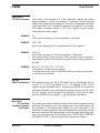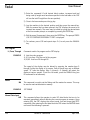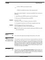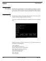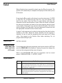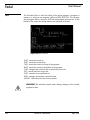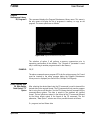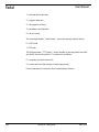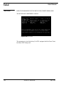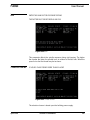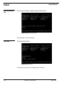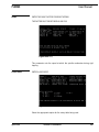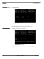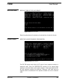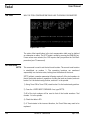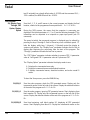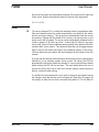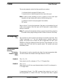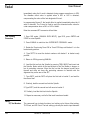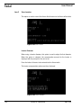
1
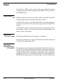
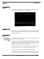
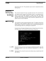
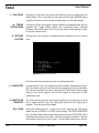
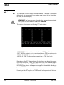
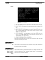
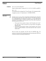
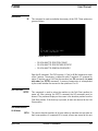
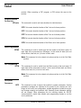
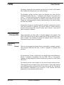
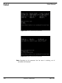
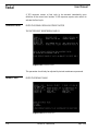
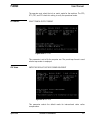
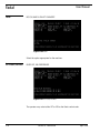
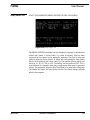
Fadal
User Manual
Section 8: Commands
Table 1: Command List
DESCRIPTION
COMMAND
PARAMETERS
AUTO:
AU,
From, to, dry run option, direct block start
BACKLASH:
BL,
Axis no., amount at center, at - limit, at + limit
CHANGE DEVICE:
CD,
Baud rate, line feed option, command echo, device option
CHANGE PROGRAM BLOCKS:
CH,
From, through
COPY PROGRAM BLOCKS:
CO,
From, through, to just after
COMMAND LOCK:
CL
COLD START:
CS
DISPLAY BUCKET #:
DD
DELETE PROGRAM BLOCKS:
DE,
From, through
DIAGNOSTIC MODE:
DI
(For use by trained maintenance personnel only)
DISPLAY FIXTURE OFFSETS:
DF
DISPLAY FEED FORWARD
DFF
DISPLAY TOOL TABLE:
DT
DISPLAY TOOL TIME:
DTT
DIRECT NUMERICAL CONTROL:
DNC (DNCX),
Video option, error option, dry run, start block number
DRAW:
DR,
DISPLAY VARIABLE TABLE:
DV
Displaying from, through, CRC option, list option
FIXTURE OFFSET:
FO,
HOME ALL AXES:
HO
INSERT PROGRAM BLOCKS:
IN,
From, increment
LEARN MODE:
LE,
First block number, increment
LIST PROGRAM BLOCKS:
LI,
From, through
MACROS:
MA
Number, (X amount), (Y amount), (Z amount)
MEMORY:
ME
MENU:
MU
MANUAL DATA INPUT:
MD
NEW PROGRAM:
NE
(Caution: this deletes the currently active program, see PR)
NUMBER PROGRAM:
NU,
Increment for renumbering
PROGRAM MAINTENANCE:
PR,
Program number
PROGRAM PAGE EDIT:
PA
PUNCH PROGRAM TAPE:
PU,
REINITIALIZE:
April 2003
Data option, code option, TTY option
RI
Section 8: Commands
137
Fadal
User Manual
Table 1: Command List
DESCRIPTION
COMMAND
PARAMETERS
SET(parameter):
SET
Parameter code (SETX, SETY, SETZ, SETA, SETB, SETHO,
SETME, SETIN)
SAVE PARAMETERS
SP
Parameter#, option#
SET(pallet):
SETPA/SETPB
SETTO:
This command is used to tell the control which pallet is loaded
in the machine and only occurs at start-up
SETTO
SETTO,#:
SETTO,#
SET LENGTH OFFSET:
SL,
Tool number, optional change value
SUM PROGRAM:
SU,
Displaying from, through, CRC option, list option
SURVEY:
SV
(For use by trained maintenance personnel only)
SYSTEM PARAMETERS:
SETP
TAPE READER INPUT:
TA,
Device option, error option, add at end
TOOL CHANGER HOME:
TC,
Option
TOOL PARAMETER DEFINITION:
TO,
Tool number, diameter, length off.
UTILITY:
UT,
Tool Number
VERIFICATION OF TAPE:
VT
Auto
AU, From, To, Dry
Run, Direct Block
Start
EXAMPLE:
This command is used instead of the AUTO key when a mid-program start or a
dry run is desired. The “From” parameter specifies the first block to be
executed. If it is zero, the first program block of the main program is assumed.
For mid- program starts, all machine axes are automatically positioned to the
location they would have been prior to the block specified, and all modal
function codes specified before the starting block are automatically in effect
(Spindle ON, Coolant ON, Absolute Mode, etc.). The "To" parameter specifies
the block to end program execution. If it is zero, the program is executed until
an M2 or M30 (Format 2) end of program. If the third parameter is a 1, 2, or 3,
the program will be executed in a DRY RUN mode. In this mode, all rapid moves
are under control of the feed rate override pot.
DRY RUN OPTIONS: If the third parameter is 1, the interpolation moves are
made at the programmed feed rates and point-to-point moves are at 150 IPM.
If the third parameter is 2, the interpolation moves are made at 150 IPM and
point-to-point moves are at 150 IPM.
If the third parameter is 3, the interpolation moves are at 75 IPM. and point-topoint moves are at 300 IPM.
138
Section 8: Commands
April 2003
Fadal
User Manual
If the fourth parameter is a 1, execution begins directly and the control will not
search for modal function codes specified before the block number in the first
parameter; caution must be taken. If the fourth parameter is greater than 1, the
CNC begins the modal code search starting at the block # specified by the
fourth parameter.
!
Backlash
BL, Axis No., Amount
At Center, At - Limit,
At + Limit
WARNING: The low way lube message is not displayed when
continuously looping a program in the Auto mode. The operator MUST
monitor the way lube level to ensure proper fluid levels during these
continuous operations.
This command is used to display axis backlash. It is also used to enter an
amount of backlash for each axis into the memory of the CNC. Each axis is
addressed by a number.
X = 1, Y = 2, Z = 3, A = 4, B = 5
The backlash is specified by units of one ten-thousandth of an inch. Therefore
having a value of 5 would equal .0005 in decimal inches. Example: Having
.0004" backlash at center of the Y axis.
Enter: BL,2,4
Change Device
CD, Baud Rate, Line
Feed Option,
Command Echo
Option, Device
Option
EXAMPLE:
The primary use of this command will be to prepare the RS-232-C serial I/O
port to send or receive data to or from another device such as a tape punch or
another computer (see Section 14, Communications).
BAUD RATE:
1=110 baud
2=150 baud
3=300 baud
4=600 baud
5=1200 baud
6=2400 baud
7=4800 baud
8=9600 baud
9=19,200 baud
10=38,400 baud
11=57,600 baud
12=115,200 baud
Baud rates above 9600 should only be used with Xmodem protocol. This
protocol uses error checking that is more suitable for the higher baud rates.
See the communications section for an explanation of protocol types.
April 2003
Section 8: Commands
139
Fadal
User Manual
Note: The 57,600 and 115,200 baud rates can only be established from the
Command Mode.
EXAMPLE:
LINE FEED OPTION: 1=NO LINE FEEDS TRANSMITTED TO THE RS-232 PORT
EXAMPLE:
COMMAND ECHO OPTION: 1=NO COMMAND ECHO TO THE RS232 PORT
EXAMPLE:
DEVICE OPTION: 0=THE EXTERNAL COMMUNICATIONS PORT IS ACTIVE.
1=THE INTERNAL COMMUNICATIONS PORT IS ACTIVE. PC programs on the 32
MP control may use COM2 when using this option. Type BYE or CD,# to return
the system to the machine RS-232 port.
EXAMPLE:
CD,3 Set the baud rate to 300
Send data with line feeds.
Echo all commands entered at terminal.
CD,3,1 Set the baud rate to 300
Send data without line feeds.
Echo all commands entered at terminal.
CD,3,1,1,1 Set the baud rate to 300
Send data without line feeds.
Commands entered at the terminal will not be
echoed back to the terminal.
The internal communications port is active.
Change Program
CH, From, Through
This is a command used to change one or more blocks of the program. The
CNC displays the block of data starting with the “From” parameter and
proceeds by pressing the ENTER key until the “Through” parameter (optional)
is reached. You do not need to retype the entire block. You may add, delete or
change a character already in the block.
To add to block number 30:
TYPE COMMAND:CH,30
BLOCK DISPLAY:N30 G0
TO ADD:M8
TYPE:M8
BLOCK CORRECTED:N30 G0 M8
BLOCK DISPLAY:N30 G0 M8
140
Section 8: Commands
April 2003
Fadal
User Manual
TO ADD:G90
TYPE:G0 G90 (if not the G0 is replaced by G90)
BLOCK CORRECTED:N30 G0 M8 G90
To delete from block number 30:
TYPE COMMAND:CH,30
BLOCK DISPLAY:N30 G0 M8 G90
TO DELETE:M8
TYPE:M;
BLOCK CORRECTED:G0 G90
BLOCK DISPLAY:N30 G1 X9.845
TO DELETE:45
TYPE:45;
BLOCK CORRECTED:N30 G1 X9.8
To change a character in block number 30:
TYPE COMMAND:CH,30
BLOCK DISPLAY:N30 G1 X10.986
TO CHANGE:X10.986 TO X10.988
TYPE:6;8
BLOCK CORRECTED:N30 G1 X10.988
BLOCK DISPLAY:N30 G1 X10.988
TO CHANGE:X10.988 TO 10.7
TYPE:988;7
BLOCK CORRECTED:N30 G1 X10.7
When using the through parameter, the computer prompts you with each
block, starting with the first parameter and ending at the second parameter.
You may press the ENTER key to advance to the next block whether or not you
made any changes. At any time you want to abort this mode, push the
MANUAL key.
Command Lock
CL
April 2003
The Command Lock menu is a method of locking out specific commands that
the user does not want other users to have access to. Commands that are set
to "LOCKED", will only be available if the key lock has been disabled (Key lock
switch is set to the vertical position). To edit any values, the user must move a
selector cursor defined by a * symbol around the screen. This selector cursor
can be moved up, down, left, or right by pressing the "backspace" or "U",
"enter" or "D", "L", or "R" keys respectively. To change the status of any given
command, move the selector cursor to that command's position, and press the
Section 8: Commands
141
Fadal
User Manual
space bar to toggle that commands lock/unlock status. Press the "manual" key
to save the current settings and exit from the command lock menu.
There are three commands that will not lock/unlock without the user entering a
special password. These commands are the SURVEY MENU, DIAGNOSTICS,
and the MACHINE CONFIGURATION options. If these three commands are in
the locked position, they will remain locked regardless of the key lock switch
position. These are the commands that should only be altered by a service
person.
Figure 8-1 Command Lock Menu
142
Section 8: Commands
April 2003
Fadal
User Manual
Copy Program
CO, From, Through,
To Just After
This copies one or more blocks specified by “From, Through” parameters to
just after the block specified by “To Just After” parameter. The original blocks
are not deleted. The copied blocks are renumbered as necessary to fit between
the block specified by the third parameter and the following block.
Using the following program, copy blocks from 1 through 3 to just after block 3.
Type command CO,1,3,3.
Table 2: Copy Program
ORIGINAL PROGRAM
PROGRAM AFTER COPY
N1 G0 X1.
N1 G0 X1.
N2 G1 Z-2. F25.
N2 G1 Z-2. F25.
N3 G0 Z3.
N3 G0 Z3.
N4 X6.
N3.25 G0 X1.
N3.50 G1 Z-2. F25.
N3.75 G0 Z3.
N4 X6.
Cold Start
CS
On System 97 machines the operator does not have to manually cold start the
machine. During the power on process the machine will automatically go
through the cold start procedure.
This command reinitializes the absolute table location which is required after
power on. This is Machine Zero (see Section 11, Machine Coordinate System).
The procedure is as follows:
1) Jog each axis to its indicator (Machine Zero), within .050 of either side.
2) Press AUTO key.
3) Inspect the cold start indicator positions, making sure that each indicator is
aligned.
After the Cold Start procedure has been initialized the CNC will prompt the
operator to move to the last home position or the operator can go directly to the
command mode.
April 2003
Section 8: Commands
143
Fadal
User Manual
Press AUTO or START to move to that position and establish the Tooling
Coordinate System (see SETH command). Press MANUAL to return the CNC to
the COMMAND mode.
Display Bucket #
DD
Displays the bucket number and tool number table, and identifies the bucket
number located at the bucket ready position with an asterisk.
1) SWAP TOOLS- Option 1 within DD is SWAP TOOLS, which will exchange the
tool in the spindle for the tool in the bucket ready position. The table will be
updated.
2) SORT TOOLS- Option 2 within DD will sort the tools automatically until each
tool number is located in the same bucket number. Upon completion, tool
number 1 will be in the spindle.
Delete Blocks
DE, From, Through
This deletes specified blocks from the program. For example:
DE,10 will only delete block 10. DE,10,1000 will delete all blocks starting with
10 through and including block 1000.
Display Feed
Forward Parameters
DFF (optional)
144
This command is used to display advanced feed forward parameters for tools 1
through 30. The menu at the bottom of the display is a summary of keys used
to page through the feed forward table, edit the 5 feed forward parameters,
and exit the display. Only 1 of 3 pages is displayed at a time, showing the
parameters of 12 tools. The ENTER key advances to the next page while the
BACKSPACE key pages returns to the previous page. The #1 key will allow you
Section 8: Commands
April 2003
Fadal
User Manual
to change the parameters of a tool. The space bar will exit to the tool length
offset menu.
NO.
GAIN
DECEL
ACCEL
DETAIL
FEED
1
100.0000
400.0000
10.0000
0.0100
125.0000
2
100.0000
400.0000
10.0000
0.0020
100.0000
100.0000
400.0000
10.0000
0.0002
80.0000
3
4
5
6
7
8
9
10
11
12
FEED FORWARD TABLE.....................................................PRESS MANUAL TO ABORT-1-NEW VALUE
ENTER-NEXT PAGE
BACKSPACE- PREVIOUS PAGE
SPACE- NEXT TABLE
Figure 8-2 Advanced Feed Forward Parameters
April 2003
Section 8: Commands
145
Fadal
User Manual
Display Fixture
Offsets
DF
This displays the current table of the 48 fixture offsets. In the example below,
offset 2 has a -1.0 value for the X, Y, Z, A, and B axes.
Figure 8-3 Display Fixture Offsets
Diagnostics
DI
Direct Numerical
Control
DNC, Video Option,
Error Option, Dry
Run, Start Block
Num.
This command is used by trained maintenance personnel. The Emergency
Stop history can be obtained by entering DI and pressing ENTER then entering
DE and pressing ENTER.
This command causes the CNC to execute NC code as it is received from the
RS-232 port (see Section 14, DNC).
A value of 1 for the Video Option will disable the video display. The video
parameter is also used to perform Mid Tape Starts. Enter the line number to
begin execution from. The control then processes the program from the
beginning to this line. All modal codes are processed.
A value of 1 for the Error Option disables error checking. A value of 0 checks for
syntax errors such as XX or Y—, and lines of code with only a comment.
Dry Run options are the same as the AU command Dry Run options.
The Start Block Num. is the block number to begin execution of the program.
The control ignores all program code prior to this block. This is the same as a
146
Section 8: Commands
April 2003
Fadal
User Manual
direct block start in AU. This parameter may be used in conjunction with the
Mid Tape Start.
XModem Direct
Numerical Control
DNCX, Video Option,
Error Option, Dry
Run, Start Block
Num.
This command operates the same as the DNC command. This command uses
the Xmodem protocol instead of the XON/XOFF protocol. The Xmodem protocol
allows for long term DNC operations at higher baud rates with longer
communications cables. The Xmodem protocol sends data in packets of 128
data bytes. After sending the block of data, checksum is performed. The next
packet is sent if no error is detected.
Draw
DR
This command is used to display the graphics menu. The graphics menu of the
page editor has been designed to allow the user to view the part path of the
current program in memory. The graphics can be accessed by pressing the G
Key from the page editor or by entering the command DR.
A second menu will appear, allowing the user to choose from several options.
All of these options can be selected while plotting is taking place.
Figure 8-4 Graphics Menu
April 2003
A = AUTO
Pressing the A key runs the current program completely through the part path
showing interpolation moves only (movement programmed at a feed rate
G1,G2,G3).
C = CLEAR
Pressing the C key clears the screen and continues auto part path draw at full
table plotting.
Section 8: Commands
147
Fadal
User Manual
F = FULL TABLE
Pressing the F key clears the screen and continues auto part path draw at full
table plotting. This is used after the part path plot has been ZOOMED inward
and the user wants to see the whole part path again on a full table display.
M = TOGGLE
DISPLAY MODE
Pressing the M key will toggle the options differences displayed along with the
graphics plot. Toggle display options are incremental moves, absolute
positions, and modal codes. The M key can be pressed while plotting in order
to view the various modes.
O = OPTIONS
PLOTTING
Pressing the O key displays an additional menu allowing the user to choose
from:
Figure 8-5 Plotting Options Menu
Once the option key has been pressed, the plotting continues.
148
S = SINGLE STEP
By pressing the S key, one program line will be plotted. Repeated pressing of
the S key allows the user to step through the program in line-by-line execution.
This can be canceled at any time by pressing the START button. During single
step plot the current program line will also appear on the screen in G91
incremental value.
V= VIEW TOP OR
ISOMETRIC
The V Key can be pressed at any time during plotting to change the view from
top to simple isometric view. The plotting will restart from the beginning of
program. This view may not be rotated.
JOG = ZOOM
During the plotting process, or after the full plot, pressing the JOG button
allows the user to ZOOM in or ZOOM out the display. The PULSE GENERATOR
(the Jog Hand Wheel) now controls the position where the ZOOM BOX will be
located on the screen (in this mode, JOG does not jog the machine). X and the
Hand wheel moves the box left to right. Y and the Hand wheel moves the box
Section 8: Commands
April 2003
Fadal
User Manual
up and down. Z and the Hand wheel increases or decreases the size of the box.
Locate the box and place it around the portion of the part path the user wants
to see in a larger detail. Press the ENTER button and the part path contained in
the ZOOM box will be redrawn larger. After each successive ZOOM, the pixel
size representation is located to the right of the axis location of the displayed
part path.
Display Tool Table
DT
This command is used to display tool diameters and length offsets for tools 1
through 99. The menu at the bottom of the display is a summary of keys used
to page through the tool table, edit tool data, and exit the display. Only 1 of 3
pages is displayed at a time. The ENTER key advances to the next page while
the BACKSPACE key pages returns to the previous page. The #1,#2,#3, and #4
keys enable editing functions; #1 key replaces a value, #2 key increments the
current value, #3 mass modifies the length incrementally, and #4 puts the
display into the Utilities menu.
In program FORMAT 1, an H word applies the length factor in this table for tool
length compensation and applies the diameter factor for cutter radius
compensation. In program FORMAT 2, an H word applies the length factor for
tool length compensation; the D word applies the diameter or radius (see the
SETP command) factor for cutter radius compensation.
Exit the tool table display by pressing MANUAL.
April 2003
Section 8: Commands
149
Fadal
User Manual
Display Tool Time
Table
DTT
!
This command is used to display the Tool Time table. The menu at the bottom
of the display is a summary of keys used to page through the tool time table,
edit data, and exit the display.
WARNING: Tool times become active only when appropriate parameter in
SETP page has been turned on. See SETP command
The user may choose from the following DTT table options:
Figure 8-6 DTT Table Options
1-SET USED This feature is for the expired time or USED time of the tool
2-SET TIME This feature is for the current used time or TIME the control counts
3-RESET ALL USED This feature clears expired time or USED time for all tools
4-RESET ALL TIME This feature clears current time or TIME for al tools
Depending on the SETP feature chosen, the tool times may be used to monitor
USED time and or TIME. There are 3 pages to the Tool Time Table; one page is
displayed at a time. The ENTER key advances to the next page while the
BACKSPACE key returns to the previous page. Exit the tool table display by
pressing MANUAL.
Following are the SETP options for TIMERS and a brief explanation of their use.
150
Section 8: Commands
April 2003
Fadal
User Manual
Timers
Figure 8-7 Timer Setup Menu
1) ALL TOOL TIMING OFF Do not check the tool time table; factory set to off.
2) DO NOT CHECK Tool timers will be active and count, will not check USED
time.
3) END OF TOOL(AT M6) Tool timers active and will check USED after every
M6. If US time exceeds TIME for tool specified, control will show a screen
display: TOOL HAS EXPIRED!
4) AFTER EACH MOVE Tool timers active and will check USED after every
move. If USED time exceeds TIME for tool specified, control will show a
screen display: TOOL HAS EXPIRED!
5) AT END OF PROGRAM: TOOL HAS EXPIRED!
Select the desired option and set a value in the STT table for USED. The TIME
value will be inserted by the control.
Display Variable
Table Command
DV
Fixture Offset
FO, Offset Number, X
Value, Y Value, Z
Value, A Value, B
Value
April 2003
This command is used to display macro variables 1 through 100. Variables are
accessible through a table display.
This command enters the specified distance(s) in the fixture offset table. The
offsets are relative to the Tool Coordinate System (Home). The first parameter
selects one of the 48 offsets available.
Section 8: Commands
151
Fadal
User Manual
EXAMPLE:
FO,2,-2.0,-2.0,2.0,100.0,205.7
Enters for offset number 2 a value of X-2.0, Y-2.0, Z+2.0, A100.0, and B207.5
FO,2,,,-2.0
This command will not change the X,Y,A and B values. The Z parameter will be
changed to a value of -2.0 (see Section 11, FIXTURE OFFSETS).
Home Axis
HO
Automatic return to zero position of the Tooling Coordinate System. Note that
this command operates the same as G28 in Format 1. The HO command acts
as a reset button when in Format 2. R values are not reset with the HO
command. This command is accomplished in one of two ways, according to
the current position of the Z axis.
•
•
If the current Z axis position is above (+) the Z0 position, the X and Y
axes will move to zero first, then the Z axis will move in the negative
direction to zero.
If the current Z axis position is below (-) the Z0 position, the Z axis will
move in a positive direction, to zero first, then the X and Y axes will
move to zero.
After the moves are computed, the CNC enters the WAITING state. The
operator can command the execution of the moves by pressing the START key
or abort the moves by pressing the MANUAL key.
152
Section 8: Commands
April 2003
Fadal
User Manual
Insert Blocks
IN, From, Increment
EXAMPLE:
IN
Insert blocks starting with 1 and incremented by 1 thereafter.
EXAMPLE:
IN,2.5,.001
Insert blocks starting with 2.5 and incremented by .001 thereafter.
EXAMPLE:
IN,10,10
Insert blocks starting with 10 and incremented by 10 thereafter.
Each time the editor is ready to receive a block it prompts you by printing the
next sequence number. Enter a block by typing the various words you desire in
the block.
EXAMPLE:
N10 G2 X.707 Y.293 I.707 J-.707 F4.0
The spaces in the above line are optional.
To exit the insert mode, press the ENTER key after the system has prompted
you with a new line number.
Jog Axis
J(Axis ID) (Direction)
Learn Mode
LE, First Block
Number, Increment,
Tool Number
April 2003
Insert blocks in the program. The “From” parameter specifies the starting
sequence number. If “From” is not specified, 1 is assumed. The next sequence
number will be determined by adding the “Increment” parameter to the present
sequence number. If the “Increment” parameter is not specified, 1 is assumed.
The smallest increment allowed is .001, thus allowing insertion without
renumbering the entire program.
This command places the CNC in JOG mode. The axis identification must be
one of X, Y, Z, A or B. The direction is + or -. For example, to JOG Y in the
negative direction you would type JY- and then press ENTER. The commas for
parameter separation are not used with this command. Once in the JOG mode,
the axis, direction, and feed range will be displayed. To exit the JOG mode,
press the MANUAL key (see Section 7, Jog Key and the Hand Wheel).
The primary use of this command is to enter blocks into the program from the
jog mode. One example of use is the cleaning out of an irregular pocket. The
first parameter is the starting block number, the second parameter is the
increment of numbering (the first and second parameters are used the same as
the insert command), the third parameter is the tool length offset being used.
Once in the learn mode the CNC will prompt you to “PRESS JOG TO CONTINUE
OR MANUAL TO EXIT”. Steps for using the learn mode are as follows:
Section 8: Commands
153
Fadal
User Manual
1) Enter the command LE with desired block number, increment and tool
being used (a length must have been specified in the tool table or the CNC
will use the total Z length from the zero position).
2) Once in the learn mode press the jog key.
3) Jog the machine to the desired position and then press the manual key.
After the manual key has been pressed, the CNC displays the move to be
inserted into memory. The move may be edited by typing the desired data
at the line number prompt, or accepted by pressing the ENTER key.
4) Edit the move (if necessary), then press the ENTER key. The prompt PRESS
JOG TO CONTINUE OR MANUAL TO EXIT is displayed.
5) To continue, press JOG and repeat steps 2-4, to exit press the MANUAL
key.
List Program
LI, From, Through
EXAMPLE:
Command used to list program on the CRT display.
LI Lists the entire program
LI,10 Lists from 10 to the end of the program
LI,20,90 Lists from 20 through 90
The speed of the display may be altered by pressing the number keys 0
through 9 while the display is in process. Each of these keys sets a different
speed. “0" halts the display. Keys 1 (slowest) - 9 (fastest) will restart the
display at various speeds. To exit the List mode, press the MANUAL key (see
PA command for an alternate).
Macro
MA
EXAMPLE:
Manual Data Input
MD
154
This command is used to set the Debug and Run modes for macros. This may
be used to read variable data in memory.
SET DEBUG
This command allows the operator to enter NC data blocks that are to be
executed immediately without affecting the current program in memory. Upon
entering MDI, the CNC displays the current mode, tool and format (see SETP
command). After entering the first data block the CNC enters the WAITING state
until one of the following is pressed:
Section 8: Commands
April 2003
Fadal
User Manual
• AUTO or START key (to execute the data)
- or •
MANUAL key (to abort and return to the command mode)
Every block entered thereafter is executed immediately upon pressing the
ENTER key:
1) Type MD then press ENTER to put the control in the MDI mode.
2) Now type your CNC block and then press ENTER.
EXAMPLE:
G1 G91 Z-2. F100.
This causes a Z- move of 2.0 inches at a feed rate of 100 IPM
3) At completion of each block, the VMC waits for another block of code.
EXAMPLE:
G0 G90 Z0 Returns the Z axis to the zero position
Press the MANUAL key to return to the command mode.
Note: The MDI mode can also be entered by pressing the MANUAL key while
in the command mode.
Memory
ME
Menu
MU (when used in
the command mode)
This command will display the percentage of free memory in the control.
This command is used to access the menu of commands that are used in the
command mode. This allows you to find a command that you do not know.
Upon entering the MU command, a directory of commands and the page
number on which they appear is displayed. Type the page number on which
the desired command resides and then press the ENTER key. The ENTER and
BACKSPACE keys are used to page forward and backward through the menu.
To exit the Menu mode press MANUAL.
New Program
NE
April 2003
This command is used to remove the active program (see PR command). The
program in current memory is deleted from the control. Before removing the
active program the CNC will compress memory then verify your decision by
prompting you for a Y (yes) or N (no) response.
Section 8: Commands
155
Fadal
User Manual
Renumber Program
NU, Increment
Renumbers the current program. The value supplied as “Increment” is used as
the first block number and then is used as the step between blocks for the rest
of the program. If the “Increment” parameter is left blank, the control assumes
1.
Program Page Edit
PA
This will list the currently active program. Other functions, such as word search,
program editing and program execution are allowed.
The cursor is to the left of the listing and is controlled by one of the six following
keys.
Figure 8-8 Program Page Edit Menu
Position the cursor to a line to execute one of the following functions by
pressing the corresponding key:
C key Change line
I key Insert line after cursor line
DEL key Delete cursor line or multiple lines
S key Search for character or characters
R key Replace program words
A key Run cursor block only
H key Help menu
O key Copy lines
156
Section 8: Commands
April 2003
Fadal
User Manual
P key Program selection
N key Number lines
F key Function (Function) menu: move (cursor to position first)
G key Graphics menu (see Draw command)
AUTO key Begin program from beginning, from cursor line or search models
and begin from cursor
Editing is addressed in the same manner as the CH command. Inserting new
data blocks is addressed by the I key and it functions in the same manner as
the IN command (see CH and IN commands). Press MANUAL to exit the listing.
Function Menu
Using the Function
Menus
The Function menus are accessed through the Page Editor by pressing the F
key. The screen will display 9 different function titles and function numbers.
This menu consists of many independent functions that solve various
geometric problems. Each is designed to help the user calculate items such as
ANGLE, LINES, INTERSECTIONS, TANGENT, BLEND RADIUS, CIRCLE, and
TRIANGLE. It is also designed for creating TOOL CALL or END OF PROGRAM
coding and for defining FIXED CYCLES or SUBROUTINES.
Cursor Movement
Once in the Function menus, move the cursor up or down in the menu and
describe the items by filling the values in. To move the cursor down press the
ENTER button. To move the cursor UP press the U key.
If the value has been entered incorrectly, move the cursor to where the error is.
Then press the backspace key until it has the incorrect data is removed. When
all the data has been entered, press the C key to compute the geometry.
Getting Started
The user should always be aware of what position in the current program the
cursor is. The user should place the cursor on a line of the current program
before entering the Function menu. This line should be above the area where
the calculated information needs to be inserted. When the Function menu
inserts information into the Page editor, a comment is also inserted to indicate
which function was used.
The Menus
Once in the function title listing, select the number of the function titles until
you arrive at the individual Function menu. The cursor is located at a specific
geometric question. Fill in the blank, and then press the ENTER button to move
the cursor down to the next question. If the data has been entered incorrectly
press the U key to move the cursor upward to the data and use the Backspace
key to back over the information. Retype the data.
April 2003
Section 8: Commands
157
Fadal
User Manual
When all data has been successfully entered, press the C key for compute. The
geometry will automatically be computed and displayed at the bottom portion
of the screen.
By pressing the D key graphics will enlarge to cover the entire screen. To ZOOM
in, press the - key; to reduce the view, press the + key. If the solution is not
what the user wants, Press the S key for same function and retype the
information until the desired solution is found. When the solution is accepted,
the data may be inputted and saved to the current program after the current
cursor location. Pressing the I key will insert data into the editor. This will also
return the display to the Page editor. The current program will contain new code
with appropriate comments from the Function menu.
An entire G code program can be written by choosing from the other functions
available on the menu. Repeat the above instruction until the program is
complete. Be sure to insert the appropriate feeds and speed and Z milling
values. View program on the Graphics Menu before machining. Dry run
program before cutting the part.
Graphics Menu
see Draw command.
Background Editing
SPACE BAR or MU
(when used in the
AUTO mode)
To use background editing the programmer must have the control in AUTO and
press the SPACE BAR at the keyboard. Pressing the space bar changes the
screen and the background editing menu will appear.
While in the BACKGROUND EDIT menu the programmer now has several
options 1-DRYRUN OPTIONS, 2 - OFFSETS, 3-HELP.
Dry Run Options
158
Number
Dry Run Summary
1
Block Skip Switch Toggle: Toggles the Block Skip Switch on and off. Status of the
switch is displayed on the auto mode screen as BLK when on. A block of NC code
is ignored by the CNC when the block is preceded by a forward slash (/) and the
Block Skip Switch is toggled ON.
2
Optional Stop Switch Toggle: Toggles the optional stop switch on and off. Functions the same as the mechanical switch on the control panel (see Section 7,
Optional Stop Switch). Status of the switch is displayed on the auto mode screen
as OPT when on.
Section 8: Commands
April 2003
Fadal
User Manual
Number
Offsets
Dry Run Summary
3
Reset CNC Modal Values: Resets modal codes to the default values that are
selected via the SETP command.
9
Dry Run Option: Program execution in a dry run mode. Interpolation moves (G1G3) are made at the programmed feed rates and rapid moves are at 150 IPM.
10
Dry Run Option: Program execution in a dry run mode. Interpolation moves (G1G3) are made at 150 IPM and rapid moves are at 150 IPM.
11
Dry Run Option: Program execution in a dry run mode. Interpolation moves (G1G3) are at 75 IPM and rapid moves are at 300 IPM.
12
M,S,T Function Lockout: Program execution disabling all M, S, T functions; spindle on, coolant on etc. will be ignored.
13
Z Axis and M6 Lockout: Program execution disabling Z axis moves and tool
changes. This option will reduce the control look ahead. After cancellation of this
option, the Z axis will move on the next line with a Z axis programmed move.
14
No Look Ahead (For Dry Run): Normally the CNC look ahead is 90 user defined
data blocks; this function reduces the look ahead to 2 blocks.
15
Display Clocks: Displays all real time clocks for power on, running, last part, current part and current time.
19
Cancel All Dry Run Modes: Restores program execution as programmed. This
cancels options 9 through 14.
Four tables can be edited: tool offset, fixture offset, tool time and macro
variables tables (See DF, DT, DTT and FO commands).
To exit the menus press the MANUAL key.
April 2003
Section 8: Commands
159
Fadal
User Manual
The Functions Menu is used for editing of the active program, a program in
memory, or writing a new program, similar to PAGE EDIT (PA). The currently
active program that is running in AUTO will be displayed to the screen. At the
bottom of the screen the editing features are displayed as follows:
Help
Figure 8-9 Editing Features
U KEY moves the cursor up
D KEY moves the cursor down
T KEY moves the cursor to the top of the program
B KEY moves the cursor to the bottom of the program
C KEY changes line or edit the line on which the cursor sits
I KEY inserts below the cursor line
S KEY searches for a specified word
R KEY searches and replace a specified word
JOG KEY JOGs away from the current position
!
160
WARNING: Be extremely careful when making changes to the current
program in auto!
Section 8: Commands
April 2003
Fadal
User Manual
Program
Maintenance Library
PR, Program #
This command displays the Program Maintenance Library menu. This menu is
the only means to display the list of programs in memory, or copy an old
program. The menu options are as follows:
Figure 8-10 Program Maintenance Library Menu
The selection of option 5 will perform a memory compression prior to
requesting confirmation of the deletion. The “Program #” parameter is used
only in switching to another program stored in the memory.
EXAMPLE:
PR,22
The above command causes program #22 to be the active program. An O word
must be inserted in the active program before the Program Maintenance
Library menu is displayed (see Section One, Multiple Part Program).
Punch Program Tape
PU, Data Option,
Code Option, TTY
Option
After selecting the desired baud rate, the PU command is used to transmit the
desired data in the required format. The PU command will not punch a program
that is using the no edit function. See the CD (change device) command for the
communications options. The data is output in the standard left justified
format. The tool offsets are output in the format of the TO command followed
by the fixture offsets output in the format of the FO command. The first
parameter, “Data Option”, selects one of four possible formats as follows:
0 = program, tool and fixture data
April 2003
Section 8: Commands
161
Fadal
User Manual
1 = tool and fixture data only
2 = program data only
3 = all programs in library
4 = parameters and backlash
5 = all axis survey
The second parameter, “Code Option”, selects the desired code as follows:
0 = ASCII code
1 = EIA code
The third parameter, “TTY Option”, selects whether or not tape leader and nulls
are sent to the receiving device. The options are as follows:
0 = computer (no leader and nulls)
3 = leaders and nulls (for teletype or paper tape punch)
Further information is covered in the Communications Section.
162
Section 8: Commands
April 2003
Fadal
User Manual
Reinitialize
RI
This command is used to reinitialize the memory of the CNC. Three options are
given as follows:
Figure 8-11 Reinitialize Options
•
•
•
DO YOU WANT TO ZERO TOOL TABLE?
DO YOU WANT TO ZERO FIXTURE OFFSETS?
DO YOU WANT TO REINITIALIZE MEMORY?
Enter the RI command. The CNC requires a Y (Yes) or N (No) response for each
of the 3 options. The memory is cleared for each Y response. A Y response for
option C requires you to Cold Start the machine (see CS command) and reset
tool order (see SETTO command). A memory compression is accomplished
by the control whether the answers to the options are Y or N.
Set Cold Start
SETCS
Set Home Position
Of All Axes
SETH
April 2003
This command is used to return the machine to the Cold Start position for
power off. After entering the SETCS command the HO command must be
entered. The positional display on the screen is the absolute position from the
Cold Start position. If the Auto key is pressed, all axes are returned to the Cold
Start position.
The current absolute locations of all axes relative to machine zero are taken as
their home positions. If command HO is issued, all axes are moved to this zero
Section 8: Commands
163
Fadal
User Manual
position. When executing a CNC program, a G28 returns the axes to this
position.
Set Home Position
For One Axis
SET(axis)
This command is used to set home locations for individual axes.
SETX Set current absolute location of the X axis as its home position.
SETY Set current absolute location of the Y axis as its home position.
SETZ Set current absolute location of the Z axis as its home position.
SETA Set current absolute location of the A axis as its home position.
SETB Set current absolute location of the B axis as its home position.
Metric Programming
SETME
This command is used to switch from the Inch mode to the Metric mode. All
input data will be processed as Millimeters. In this mode all data (tool and
fixture offsets, feed rate, etc.) is to be in Metric units.
Note: This command is to be entered only when machine is at the Cold Start
position.
Inch Programming
SETIN
This command is used to switch from the Metric mode to the Inch mode. All
input data will be processed as inches. In this mode all data (tool and fixture
offsets, feed rate, etc.) is to be in Inch units.
Note: This command is to be entered only when machine is at the Cold Start
position.
Set System
Parameters
SETP
164
This command is used to access the machine’s system parameters. System
parameters configure the software for the model of your machine for such
things as axis travel, axis configuration, spindle adjustment, spindle drive type,
tool changer capacity and pendant style. Generally these parameter settings
will not change. Other parameters are for selecting modes for RS-232
communications, modal code defaults and programming formats to suit the
user’s preference.
Section 8: Commands
April 2003
Fadal
User Manual
The factory settings for your machine are listed on the inside of the pendant
door. Update this listing any time you make a change.
The parameter settings and their values are displayed as a menu with the
individual parameter with the “*” displayed at the bottom of the screen. The
cursor,"*", is moved with the Enter key, Backspace key, D key, and U key. When
the cursor is moved the parameter is displayed at the bottom of the screen.
Change the value by typing the number corresponding to the desired setting,
and then press ENTER.
All parameter settings are initialized when the machine is powered on and the
Cold Start procedure is executed. The default values for modal codes are
initialized when entering MDI, the AUTO mode, and in Format 1, when an M2
(end of program) is detected.
Pallet Programming
SETPA and SETPB
Programming
Formats
Formats
These commands set which pallet is currently loaded in the machine. Use
SETPA (Set Pallet A) if the A pallet is loaded and SETPB (Set pallet B) if the B
pallet is loaded. The software will prompt the operator when to enter these
commands during the start-up procedure.
There are two programming formats that are selectable by parameter settings.
These formats determine the style in which a program is formatted and
executed.
For the most part, Format 1 and Format 2 are identical with minor differences.
Format 2 maximizes compatibility with the 6MB, 10M or 11M controls.
Therefore, existing programs for these controls can be used in the CNC 88 and
CNC 88 HS.
The following are the screen displays for the various formats and processors.
These examples may not apply to your specific machine. The displays depicted
on the following pages are typical of the screens that you will see. The specific
data displayed is dependent on the processor in your machine and which
parameter you have selected with the cursor.
April 2003
Section 8: Commands
165
Fadal
User Manual
Format 1
Figure 8-12 Format 1 Screen Display
Figure 8-13 Format 1 Screen Display (continued)
166
Section 8: Commands
April 2003
Fadal
User Manual
Figure 8-14 Format 1 Screen Display (continued)
Format 2
Figure 8-15 Format 2 Screen Display
April 2003
Section 8: Commands
167
Fadal
User Manual
Figure 8-16 Format 2 Screen Display (continued)
Figure 8-17 Format 2 Screen Display (continued)
Note: Depending on the parameter that the cursor is selecting, not all
parameters are displayed.
168
Section 8: Commands
April 2003
Fadal
Operation Formats
User Manual
THERE ARE TWO PROGRAM OPERATION FORMATS AVAILABLE
Figure 8-18 Operation Formats
This parameter allows the user to select 6MB/10M/11M compatibility. The
operational difference between the two formats depends upon the coding
used.
AXES:X,Y,Z
ENTER THE AXIS CONFIGURATION
Figure 8-19 Axis Configuration
When selecting the A or B axes, the machine should be powered off. When the
power is returned the axes will be active.
April 2003
Section 8: Commands
169
Fadal
DEFAULT: G0
User Manual
ENTER THE DEFAULT VALUE
Figure 8-20 Default Value G0
The code selected is active at power on and when entering the MDI mode.
DEFAULT: G90
ENTER THE DEFAULT VALUE
Figure 8-21 Default Value G90
The code selected is active at power on and when entering the MDI mode.
170
Section 8: Commands
April 2003
Fadal
DEFAULT: G17
User Manual
ENTER THE DEFAULT VALUE
Figure 8-22 Default Value G17
This parameter is used to select the default machine plane.
RPM FACTOR
ENTER THE SPINDLE RPM ADJUSTMENT FACTOR
Figure 8-23 RPM Factor
This parameter should only be adjusted by trained maintenance personnel.
April 2003
Section 8: Commands
171
Fadal
BAUD RATE: 2400
User Manual
ENTER THE DEFAULT BAUD RATE (THE RATE AFTER POWER-ON)
Figure 8-24 Enter Default Baud Rate
The operator may select the desired communications baud rate.
Note: The 57,600 and 115,200 baud rates are available but not listed. These
baud rates must be established from the Command Mode.
TRAVEL
ENTER X, Y, Z TRAVEL.
Figure 8-25 Travel
The machine travel is selected with this parameter.
172
Section 8: Commands
April 2003
Fadal
Tool Changer Cap
User Manual
ENTER THE TOOL CHANGER CAPACITY
Figure 8-26 Tool Changer Capacity
Select the appropriate tool changer capacity.
Timers
SELECT THE AUTOMATIC TOOL TIMER MODE
Figure 8-27 Automatic Toll Timer Mode
Select the desired option and set a value in the DTT table for USED. The TIME
value will be inserted by the control. See DTT command.
April 2003
Section 8: Commands
173
Fadal
Spindle Type
User Manual
ENTER THE SPINDLE DRIVE TYPE & RPM
Figure 8-28 Spindle Drive Type
Select the correct spindle type for the machine. This parameter is set at the
factory.SPINDLE AFTER M6:
Spindle After M6
SHOULD SPINDLE COME ON AUTOMATICALLY AFTER A TOOL CHANGE WHEN
THE M6 HAD TO TURN THE SPINDLE OFF?
Figure 8-29 Spindle After M6
When this parameter is selected as YES, the spindle automatically turns on
after the tool change. The spindle comes on at the last programmed spindle
speed. This may cause an overspeed of the next tool. It is recommended that
this parameter is set to number 1.
174
Section 8: Commands
April 2003
Fadal
Pendant
User Manual
ENTER THE PENDANT STYLE
Figure 8-30 Pendant
Select the appropriate pendant location for the machine. When option two is
selected the table may make a Y axis positive move before a tool change. This
occurs only when the Y axis is five inches or more, in the negative direction,
from the cold start position.
Imm. Fixed Cycle
SHOULD A FIXED CYCLE EXECUTE IMMEDIATELY?
Figure 8-31 Imm. Fixed Cycle
April 2003
Section 8: Commands
175
Fadal
User Manual
A YES response causes a fixed cycle to be executed immediately upon
definition at the current axis location. A NO response requires axis motion to
activate the fixed cycle.
Orientation Factor
ENTER THE SPINDLE RPM ADJUSTMENT FACTOR
THE FACTOR MUST BE BETWEEN 0 AND 31
Figure 8-32 Orientation Factor
This parameter should only be adjusted by trained maintenance personnel.
DEFAULT: INCH
ENTER THE DEFAULT VALUE
Figure 8-33 Default Value: Inch
176
Section 8: Commands
April 2003
Fadal
User Manual
The operator must select the inch or metric mode for the machine. The G70,
G71, G20, and G21 check this setting to verify the operational mode.
PU FORMAT
SELECT PUNCH OUTPUT FORMAT
Figure 8-34 PU Format
This parameter is set to file for computer use. The punch tape format is used
when a tape reader is employed.
CRC Mode
ENTER THE DEFAULT OUTSIDE CORNER MOVEMENT
Figure 8-35 CRC Mode
This parameter selects the default mode for intersectional cutter radius
compensation.
April 2003
Section 8: Commands
177
Fadal
Pallet
User Manual
DO YOU HAVE A PALLET CHANGER?
Figure 8-36 Pallet
Select the option appropriate for the machine.
M7-FLOOD, M8-MIST
ENTER M7, M8 PREFERENCE
Figure 8-37 M7-Flood, M8-Mist
The operator may select either M7 or M8 as the flood coolant code.
178
Section 8: Commands
April 2003
Fadal
Binary Buffers 255
User Manual
SELECT THE NUMBER OF BINARY BUFFERS FOR CNC LOOK-AHEAD.
Figure 8-38 Binary Buffers: 255
The BINARY BUFFERS parameter can be changed to increase or decrease the
control look ahead. A binary buffer is a block of memory that has been
processed by the control and is waiting for execution. One line of code may
produce numerous binary blocks. A simple drill code generates three binary
blocks: the XY position, the Z down, and Z up. The number of binary blocks can
be set at 15, 30, 50, 100, or 255. The factory sets the buffers at 255. This is
most effective for programs with many small moves that must be executed
rapidly. This parameter helps the Run Time Menu to be used more effectively.
The smaller the buffers the more quickly the Run Time Menu changes will take
effect in the program.
April 2003
Section 8: Commands
179
Fadal
Turret Factor
User Manual
ENTER THE ENGAGEMENT FACTOR FOR THE TOOL TURRET GENEVA GEAR
THE FACTOR MUST BE BETWEEN 1 AND 50
Figure 8-39 Turret Factor
This parameter is set at the factory. For VMCs equipped with the Servo-Turret,
this factor MUST always be 1.
180
Section 8: Commands
April 2003
Fadal
Gain
User Manual
ENTER THE GAIN FACTOR FOR RIGID TAPPING
THE FACTOR MUST BE BETWEEN 0 AND 255
Figure 8-40 Gain
This parameter affects the spindle response during rigid tapping. The higher
the number the faster the spindle turns in relation to the feed rate. When the
speed is too fast the thread may be too loose.
3 Phase 5% Low: No
IS YOUR 3 PHASE POWER MORE THAN 5% LOW?
Figure 8-41 3 Phase 5% Low
The selection chosen is based upon the building power supply.
April 2003
Section 8: Commands
181
Fadal
High Torque/Rigid
Tap
User Manual
DO YOU HAVE THE HIGH TORQUE OR RIGID TAP OPTION?
Figure 8-42 HighTorque/Rigid Tap
This parameter is set at the factory.
CMD Menu
TURN COMMAND MENUS:
Figure 8-43 CMD Menu
The operator may select the command menu structure.
182
Section 8: Commands
April 2003
Fadal
Ramp
User Manual
ENTER THE RAMP FACTOR FOR RIGID TAPPING
THE FACTOR MUST BE BETWEEN 0 AND 255
Figure 8-44 Ramp
This parameter sets the speed at which the spindle accelerates during rigid
tapping.
A-Axis Ratio
ENTER A-AXIS RATIO
Figure 8-45 A-Axis Ratio
Select the appropriate option for the rotary table being used.
April 2003
Section 8: Commands
183
Fadal
B-Axis Ratio
User Manual
ENTER B-AXIS RATIO
Figure 8-46 B-Axis Ratio
Select the appropriate option for the rotary table being used.
M60/A-Axis Brake
DOES M60 TURN ON THE A-AXIS BRAKE?
Figure 8-47 M60/A-Axis Brake
Select the option desired to activate or de-activate the air brake for the axis.
184
Section 8: Commands
April 2003
Fadal
M62/B-Axis Brake
User Manual
DOES M62 TURN ON THE B-AXIS BRAKE?
Figure 8-48 M62/B-Axis Brake
Select the option desired to activate or de-activate the air brake for the axis.
N-Words Ordered
ENTER THE N-WORD SEQUENCE CONFIGURATION
Figure 8-49 N-Words Ordered
The CNC 88 requires each block of NC code to have sequence numbers in
numerical order. Since the 6MB/10M/11M controls do not require block
numbers in numerical order, select option number 2. Upon tape input the CNC
will add sequence numbers for reference. Otherwise, after tape input the
program must be renumbered if the sequence numbers are not in numerical
order.
April 2003
Section 8: Commands
185
Fadal
Tool Table
User Manual
WILL THE TOOL COMPENSATION TABLE HAVE THE RADIUS OR DIAMETER?
Figure 8-50 Tool Table
The cutter offset specification in the tool compensation table may be defined
as a diameter or radius. The SETP mode is exited by pressing the MANUAL key.
If new values were selected, the CNC requires that you perform the Cold Start
procedure (see CS command).
Set Turret Order
SETTO
This command is used to set the tool turret location. The current turret location
is established as number 1. The remaining locations are numbered
sequentially in a clockwise order, looking from the bottom of the turret.
SETTO without a number parameter following resets all of the tool numbers to
that of the bucket numbers, regardless of where the tools are located, and sets
bucket 1 at t he bucket ready position, and tool 1 in the spindle.
1) Using Turret CW or Turret CCW, rotate bucket 1 to the bucket ready position.
2) From the <ENTER NEXT COMMAND> line, type SETTO.
3) All of the tool numbers will be reset to that of the bucket numbers. Tool
number 1 is in the spindle.
4) Check the table in DD.
5) If Turret rotates in the incorrect direction, the Turret Motor may need to be
rephased.
186
Section 8: Commands
April 2003
Fadal
User Manual
SETTO,#
SETTO,# is used to reset the Turret locations by specifying that “#” is the
number of the bucket (not the tool number) located at the bucket ready position
and ready to be exchanged. The remaining bucket and tool numbers are
recovered as the sequence is retained.
1) Rotate the Turret using Turret CW or Turret CCW at ;east one position until
the desired bucket number (not tool number) is at the bucket ready position.
2) If Turret rotates in the incorrect direction, the Turret Motoe may need to be
rephased.
3) From the <ENTER NEXT COMMAND> line, type SETTO,# where # is the
bucket number of the bucket now at the bucket ready position, and ready to
exchange tools.
4) The sequence of the remaining tools in the Turret is not changed, and the
new bucket numbers are updated in the DD table. The asterisk identifies the
bucket in the bucket ready position.
5) The SETTO,# procedure may be repeated as many times as needed.
Set Tool Length
Offset
SL, Tool Number,
Optional Change
Value
This commands automatic entry of tool length compensations. The procedure
is as follows:
1) Set the home position using the SET(parameter) command.
2) Install tool in the spindle.
3) Press the MANUAL key to enter the command mode.
4) Press the JOG key to enter the jog mode.
5) Jog the Z axis until the tool is in the proper location.
6) Press the MANUAL key to enter the command mode.
7) Type SL comma and the tool number.
8) Press the ENTER key to insert this location in the tool table.
If the second parameter is a number other than zero, the current location of the
Z axis is ignored and the current value of the length offset in the tool table is
incremented by the value specified by the second parameter. For Example; If
April 2003
Section 8: Commands
187
Fadal
User Manual
tool #1 originally has a length offset value of -10.000 and the command SL,1,.025 is entered, the NEW offset will be -10.025.
Sum Program
SU, Display From,
Through, CRC
Option, Display
Option
Sum the X, Y, Z, A, and B moves in the current program and display the final
location, relative to the programmed home position as: X= Y= Z= A= B=.
During the SUM process, the moves that the computer is processing are
displayed if the fourth parameter is 1, 2, or 3 (see the following examples). This
information can be outputted to a computer or paper tape punch (see CD
command).
The speed at which the processed program is displayed may be altered by
pressing the keys 0 through 9. Each of these keys sets a different speed. “0"
halts the display, while keys 1 (slowest) - 9 (fastest) restart the display at
various scroll speeds. The “Display From” parameter indicates the first line to
display after beginning the processing from the start of the program. The
“Through” parameter indicates the last line to process.
The “CRC Option” parameter indicates whether to process CRC. A parameter
value of 1 will ignore CRC. A parameter value of 0 processes CRC.
The “Display Option” parameter indicates the display mode to use.
A 1 displays the incremental move only.
A 2 displays incremental moves and absolute locations.
A 3 displays incremental moves, absolute locations, and active modal G
codes.
To abort the Sum process, press the MANUAL key.
188
SU,0,0,0,1
Sum the entire program, check the CRC generated moves. Display only the
incremental moves on the left side of the screen. Display the absolute location
of the end of the program as X= Y= Z= A= B=.
SU,10,0,1,1
Sum the entire program, ignoring CRC generated moves. Start displaying from
block number 10. Display only the incremental moves on the left side of the
screen. Display the absolute location of the end of the program as X= Y= Z= A=
B=.
SU,10,50,0,2
Sum from beginning, until block number 50, displaying all CRC generated
moves. Start displaying from block 10. Display the incremental moves on the
Section 8: Commands
April 2003
Fadal
User Manual
left side of the screen and the absolute locations of the moves on the right side
of the screen. Display the absolute location of the end of the program as
X= Y= Z= A= B=.
Survey
SV
The survey command SV is a utility that manages the axis compensation data.
Each axis controller stores the screw compensation, zero offset for the scales,
and the servo gain settings. The survey menu automatically loads the survey
into memory, starting with the default X Axis survey. If no survey exists, a new
empty survey will be created. The survey is then automatically displayed on the
screen in groups of 40 values at a time. If more than 40 values in any given
survey exist, there will be an additional option located at the bottom of the first
column called "survey values". This option will allow the user to toggle between
Page 1 (the first 40 values) and Page 2 (the remaining values), of the survey.
The zero offset and gain options are also displayed on the bottom of the first
column.
A survey may be saved by either exiting out of the survey menu by pressing the
Manual key, or by selecting another survey to edit. On exiting, the CNC will
automatically cold start to enable the changes. If a survey has not been altered
before exiting, the CNC will not cold start. This new feature allows the user to
go into the survey menu just to look at the current settings, without having to
wait for a cold start when exiting.
If a mistake has been made and a user wants to reload an axis without saving
the changes, move the selector cursor to display the "Enter Axis ID" prompt. At
this prompt, re-enter the axis that is currently being edited. A "Do You Want To
April 2003
Section 8: Commands
189
Fadal
User Manual
Save Survey Before Re-Loading (Y/N)" message will appear. Press "N" to
reload the survey without saving the changes.
Figure 8-51 Survey Settings
!
Tape (Program)
Input
TA, Device Option,
Error Option, Add at
the End Option
WARNING: This command should ONLY be used by trained
MAINTENANCE PERSONNEL.
The TA command first clears the current program and prepares to receive
program data blocks, tool offsets, or fixture offsets. If the current program has
an O word, it is placed into machine memory. If there is no O word in the
program, it is deleted from the machine memory.
The first parameter determines whether the data is from the tape reader of the
machine or from the RS-232-C port.
0 = Input from Tape Reader.
1 = Input through RS-232 port.
2 = Input maintenance programs from machine memory.
3 = Input probe programs from machine memory.
190
Section 8: Commands
April 2003
Fadal
User Manual
The second parameter selects the three possible error options.
1 = Indicates that the program HAS parity errors.
2 = Ignores errors on input and gives an error count after input.
Note: A block of code containing an error is ignored, an error count upon
completion of input displays the number of blocks having errors.
3 = Allows the control to accept programs from another
CNC control.
Enter a value of 1 for the third parameter if the input is to be added at the end
of the current program. After this input, the NU command is required before
editing or execution.
Note: The control will automatically delete a program from the library when the
file number of the program being received is same as the one in the library.
Tool Changer Open
TC,1
Tool Parameter
Definition
TO, Number,
Diameter, Length
Offset
This command is used to open the tool changer to manually insert tools. If the
“Option” parameter is a 1, the tool changer moves to position under the
spindle. The spindle rises to release the tool (if applicable) and waits. Press
MANUAL to return the spindle and retract the turret. If the parameter is a 2, the
machine does NOT wait with the spindle raised. The spindle and turret
immediately return.
This command is used to manually enter data in the tool compensation table.
The table contains tool diameter and length offsets for 99 tools.
EXAMPLE:
TO,6,.75,-2.75
Enters data for tool 6; a diameter of .75; a -2.75 length offset
EXAMPLE:
TO,6,,-2.75
Enters data for tool 6; the current diameter/radius of tool #6 is unchanged; a 2.75 length offset
In programming Format 1, the CNC summons these values by use of an H
word programmed in a block of NC code. The length offset value is applied
April 2003
Section 8: Commands
191
Fadal
User Manual
immediately when the H word is detected during program execution or in MDI.
The diameter offset value is applied when a G41 or G42 is detected,
compensating the value of the last designated H word.
In programming Format 2, the length offset is applied immediately when the H
word is detected. The D word is used to apply the diameter/radius value for
cutter compensation when a G41 or G42 is coded.
Enter the command DT to examine all tool data.
Tool Loading
Procedure
1. From MDI mode, (MANUAL DATA INPUT), type M19, press ENTER and
START to orient Spindle.
2. Press MANUAL to switch to the <ENTER NEXT COMMAND> mode.
3. Rotate the Turret using Turret CW or Turret CCW keys until bucket 1 is in the
bucket ready position.
4. Type SETTO to reset the bucket numbers with bucket 1 at bucket ready
position.
5. Return to MDI by pressing MANUAL.
6. Load the first tool into the Spindle by pressing TOOL IN/OUT and insert into
the Spindle. Notice which of the two keyslots in the Tool Holder is deeper, or
has a protruding setscrew. Align the tool so that the deeper keyslot faces
forward and does not have any protruding setscrew to interfere with the
alignment key on the arm of the ATC.
7. Type M6T2, and the DATC will place the first tool in bucket 2, and wait for
the second tool.
8. Similarly, load the second tool into the Spindle.
9. Type M6T2, and the second tool will move to bucket 3.
10. Similarly, load the third tool into the Spindle.
11. Repeat as necessary until all of the tools have been loaded.
Utility
UT, Tool Number
192
This command has six basic functions, tool setting cycle, fixture offset setting,
TS-20 test, and MP 8 test. The tool setting cycle may be used to input diameter
Section 8: Commands
April 2003
Fadal
User Manual
and length offsets for multiple tools. The fixture offset setting may be used to
set fixture offset locations into the fixture table. The TS-20 test is used to test
the operation of the TS-Series touch probes. The MP 8 test is used to test the
operation of the MP-Series probes. See the VMC Training manual for the
specific operation of this command.
The tool number parameter is utilized to retrieve a specific tool. UT,5 would
perform a tool change and place tool number five in the spindle.
When the UT command is entered without the tool number parameter, the
utility menu is displayed.
Offset Utility
Options:
Figure 8-52 Offset Utility Options
Offset Utility
Option 1
Tool Setting Cycle
This option is used to set tool length offsets. See the Touch Probe section of
this manual for the operation of this option.
Offset Utility
Option 2
Fixture Offset Setting
This option is used to set fixture offset locations.
FIXTURE OFFSET Menu Items:
Item 1
April 2003
Select Number/Locator
Section 8: Commands
193
Fadal
User Manual
This option displays the currently selected fixture data. The operator is then
prompted to select another fixture number. Enter the new fixture number or
press ENTER to use the same number. The fixture offset options are displayed.
Figure 8-53 Select Number/Locator
After selecting this item, the user is prompted for the fixture number.
ENTER FIXTURE OFFSET NUMBER (1-48)
Enter the number of the fixture to be set. The user is then prompted for the
locator diameter.
ENTER LOCATOR DIAMETER
When using an edge finder, enter the edge finding diameter. When using a dial
indicator, press ENTER to continue. The user is prompted for a spindle speed, if
a locator diameter is entered. Enter the desired RPM for the edge finder. The
RPM is set; however, the spindle is not started. The spindle MUST be started
manually when the operator is ready to find an edge. The fixture data and
offset options are displayed after the RPM is entered.
Note: The RPM is input without the letter S. The control returns to the
Command mode when the letter S is entered.
Item 2
194
Jog to Locate
Section 8: Commands
April 2003
Fadal
User Manual
This option prompts the user to enter the Jog mode. The operator may enter
the Jog mode and find the part edge. The operator may return to the offset
option display at any time, by pressing the MANUAL button.
Figure 8-54 Jog to Locate
April 2003
Section 8: Commands
195
Fadal
User Manual
Item 3
Store Location
This option is used to record the fixture offset location to the fixture offset table.
Figure 8-55 Store Location
Locator Diameter
When using a locator diameter, this option is used to adjust for that diameter.
When this option is selected, the compensation amount for the locator is
displayed with the prompt for the axis to set.
Press the letter of the axis to be entered into the fixture table.
The locator compensation options are then displayed.
Figure 8-56 Locator Diameter
196
Section 8: Commands
April 2003
Fadal
User Manual
Press the plus key if the locator touched the part on the axes positive side. The
control subtracts the locator compensation amount to the current location, and
stores that value in the fixture table. Press the minus key if the locator touched
the axes negative side of the part. The control adds the locator compensation
amount to the current location, and stores that value in the fixture table. Press
0 if the current location is desired. The current axis location is stored in the
fixture table. The operator is returned to the axis selection display to select the
next axis to set. Press any other key to return to the offset options. Repeat this
process for each axis to set.
Dial Indicator
The procedure for the dial indicator is the same; however, the compensation
options are not displayed. When the axis is selected the current location is
entered into the fixture offset table.
Item 4
Find Center of Circle
Figure 8-57 Find Center of Circle
Using a edge finder in the jog mode, the center of a circle can be determined.
Enter the Jog mode by pressing the JOG button, touch the edge finder to the
circumference, then press the MANUAL button to enter the coordinates for the
first point. Repeat this procedure touching at 2 other points on the
April 2003
Section 8: Commands
197
Fadal
User Manual
circumference of the circle. The center will be calculated using these
coordinates by pressing the C button.
Figure 8-58 Edge Finder
The data can then be inserted into the fixture offset table by pressing the I
button.
Figure 8-59 Fixture Offset
To exit this option press the X button.
Item 5
Find Midpoint
Using the edge finder as described in the preceding paragraph, the mid point
between two planes or edges can be found and entered in the fixture offset
table.
198
Section 8: Commands
April 2003
Fadal
User Manual
Item 6
Find Corner
Using the edge finder as described in the proceeding paragraph, the corner
between two intersecting planes or edges can be found and entered in the
fixture offset table.
Item 7
Find 90° Corner
Using the edge finder as described in the proceeding paragraph, a 90° corner
between two points can be found and entered in the fixture offset table.
Item 8
Move to Fixture Offset
The fixture offset calculated in Options 4-7 can be activated with this option.
This will move the machine to that fixture offset’s coordinates.
Item 9
Exit
Selecting this option exits to the Utilities menu.
Offset Utility
Option 3
Test TS-20 Probe
This option is used to test the TS- touch probe. See the Touch Probe section of
this manual.
Offset Utility
Option 4
Test MP Probe
This option is used to test the MP probe. See the Touch Probe section of this
manual.
Offset Utility
Option 5
Pallet Changer
This option displays the pallet changer utility menu. See the Pallet Changer
section of this manual.
April 2003
Section 8: Commands
199
Fadal
User Manual
Offset Utility
Option 6
Clocks
This option is used to display the clock service utility.
Figure 8-60 Clock Service Utility
Item 1
Display Clocks
Select this option to display all current clock settings.
Figure 8-61 Display Clocks
The current time is displayed at the top. The power on time is the amount of
time since the last reset. Time is accumulative from each power on.
200
Section 8: Commands
April 2003
Fadal
User Manual
Running time is the total accumulative time that the machine has been in the
AUTO mode. The time is suspended when the machine is in the WAITING state.
This is time is accumulative from the last reset.
The last part time is running time of the last program run. When the AUTO
mode is entered the clock stops. The time stops when the M2 or M30 is
performed. Running time only is used.
The current part time is the current running time of the program in execution.
Item 2
Set Time
This option allows the user to set the current time. The previous time is
displayed with the prompt to enter the new time. Press ENTER to retain the
current time setting. Enter new times using a twelve hour clock. The AM or PM
MUST be entered.
Note: This setting cannot be changed with the key lock on.
Item 3
Reset Clocks
When option three is selected, all clocks, except current time and tool time, are
reset to zero.
To reset tool time go to the DTT table.
Note: This option is not functional when the key lock is on.
Item 4
Exit
Select this option to return to the Offset Utility Options menu.
April 2003
Section 8: Commands
201
Fadal
Tape Verification
VT, Device Option
User Manual
This command reads a paper tape that is punched by the VMC. Using a check
sum routine, the control verifies the punched tape. The CNC displays the
message TAPE IS GOOD indicating a successful punch.
The “Device Option” parameter of 1 indicates use of the RS-232 port to read
the tape. This parameter is a 0 if the control is to use the machine tape reader.
The procedure is as follows:
1) Type the command: VT,1 then press the ENTER key.
2) Start the tape reader.
3) Stop the tape reader when done.
202
Section 8: Commands
April 2003