1
Mitsubishi Industrial Robot
RH-1FHR-S60 Series
INSTRUCTION MANUAL
ROBOT ARM SETUP & MAINTENANCE
BFP-A3335-B
Safety Precautions
Always read the following precautions and the separate "Safety
Manual" before starting use of the robot to learn the required
measures to be taken.
CAUTION
CAUTION
WARNING
CAUTION
DANGER
CAUTION
CAUTION
CAUTION
All teaching work must be carried out by an operator who has received special
training. (This also applies to maintenance work with the power source turned
ON.)
Enforcement of safety training
For teaching work, prepare a work plan related to the methods and procedures
of operating the robot, and to the measures to be taken when an error occurs
or when restarting. Carry out work following this plan. (This also applies to
maintenance work with the power source turned ON.)
Preparation of work plan
Prepare a device that allows operation to be stopped immediately during
teaching work. (This also applies to maintenance work with the power source
turned ON.)
Setting of emergency stop switch
During teaching work, place a sign indicating that teaching work is in progress
on the start switch, etc. (This also applies to maintenance work with the power
source turned ON.)
Indication of teaching work in progress
Provide a fence or enclosure during operation to prevent contact of the
operator and robot.
Installation of safety fence
Establish a set signaling method to the related operators for starting work, and
follow this method.
Signaling of operation start
As a principle turn the power OFF during maintenance work. Place a sign
indicating that maintenance work is in progress on the start switch, etc.
Indication of maintenance work in progress
Before starting work, inspect the robot, emergency stop switch and other
related devices, etc., and confirm that there are no errors.
Inspection before starting work
The points of the precautions given in the separate "Safety Manual" are given below.
Refer to the actual "Safety Manual" for details.
DANGER
CAUTION
CAUTION
CAUTION
CAUTION
CAUTION
CAUTION
WARNING
WARNING
CAUTION
WARNING
CAUTION
CAUTION
CAUTION
CAUTION
When automatic operation of the robot is performed using multiple control
devices (GOT, programmable controller, push-button switch), the interlocking of
operation rights of the devices, etc. must be designed by the customer.
Use the robot within the environment given in the specifications. Failure to do
so could lead to a drop or reliability or faults. (Temperature, humidity,
atmosphere, noise environment, etc.)
Transport the robot with the designated transportation posture. Transporting
the robot in a non-designated posture could lead to personal injuries or faults
from dropping.
Always use the robot installed on a secure table. Use in an instable posture
could lead to positional deviation and vibration.
Wire the cable as far away from noise sources as possible. If placed near a noise
source, positional deviation or malfunction could occur.
Do not apply excessive force on the connector or excessively bend the cable.
Failure to observe this could lead to contact defects or wire breakage.
Make sure that the workpiece weight, including the hand, does not exceed the
rated load or tolerable torque. Exceeding these values could lead to alarms or
faults.
Securely install the hand and tool, and securely grasp the workpiece. Failure to
observe this could lead to personal injuries or damage if the object comes off or
flies off during operation.
Securely ground the robot and controller. Failure to observe this could lead to
malfunctioning by noise or to electric shock accidents.
Indicate the operation state during robot operation. Failure to indicate the state
could lead to operators approaching the robot or to incorrect operation.
When carrying out teaching work in the robot's movement range, always secure
the priority right for the robot control. Failure to observe this could lead to
personal injuries or damage if the robot is started with external commands.
Keep the jog speed as low as possible, and always watch the robot. Failure to do
so could lead to interference with the workpiece or peripheral devices.
After editing the program, always confirm the operation with step operation
before starting automatic operation. Failure to do so could lead to interference
with peripheral devices because of programming mistakes, etc.
Make sure that if the safety fence entrance door is opened during automatic
operation, the door is locked or that the robot will automatically stop. Failure to
do so could lead to personal injuries.
Never carry out modifications based on personal judgments, or use nondesignated maintenance parts.
Failure to observe this could lead to faults or failures.
WARNING
CAUTION
CAUTION
DANGER
DANGER
DANGER
CAUTION
CAUTION
When the robot arm has to be moved by hand from an external area, do not
place hands or fingers in the openings. Failure to observe this could lead to
hands or fingers catching depending on the posture.
Do not stop the robot or apply emergency stop by turning the robot controller's
main power OFF. If the robot controller main power is turned OFF during
automatic operation, the robot accuracy could be adversely affected. Moreover,
it may interfere with the peripheral device by drop or move by inertia of the arm.
Do not turn off the main power to the robot controller while rewriting the
internal information of the robot controller such as the program or parameters.
If the main power to the robot controller is turned off while in automatic
operation or rewriting the program or parameters, the internal information of the
robot controller may be damaged.
Do not connect the Handy GOT when using the GOT direct connection function
of this product. Failure to observe this may result in property damage or bodily
injury because the Handy GOT can automatically operate the robot regardless
of whether the operation rights are enabled or not.
Do not remove the SSCNET III cable while power is supplied to the controller.
Do not look directly at light emitted from the tip of SSCNET III connectors or
SSCNET III cables. Eye discomfort may be felt if exposed to the light.
(Reference: SSCNET III employs a Class 1 or equivalent light source as
specified in JIS C 6802 and IEC60825-1 (domestic standards in Japan).)
Attach the cap to the SSCNET III connector after disconnecting the SSCNET
III cable. If the cap is not attached, dirt or dust may adhere to the connector
pins, resulting in deterioration connector properties, and leading to malfunction.
Make sure there are no mistakes in the wiring. Connecting differently to the way
specified in the manual can result in errors, such as the emergency stop not
being released. In order to prevent errors occurring, please be sure to check
that all functions (such as the teaching box emergency stop, customer emergency stop, and door switch) are working properly after the wiring setup is completed.
Use the network equipments (personal computer, USB hub, LAN hub, etc)
confirmed by manufacturer. The thing unsuitable for the FA environment
(related with conformity, temperature or noise) exists in the equipments
connected to USB. When using network equipment, measures against the noise,
such as measures against EMI and the addition of the ferrite core, may be
necessary. Please fully confirm the operation by customer. Guarantee and
maintenance of the equipment on the market (usual office automation
equipment) cannot be performed.
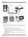
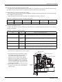
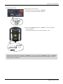
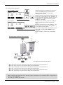
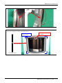
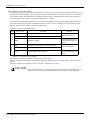
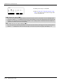
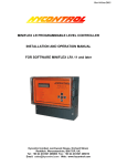
*CR751-D or CR751-Q controller
Notes of the basic component are shown.
CAUTION
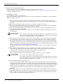
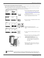
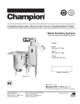
Please install the earth leakage breaker in the primary side supply power supply
of the controller of CR751-D or CR751-Q because of leakage protection.
Controller
Controller
Three phase
AC200V
Single phase
AC200V
* The controller is an
example.
ACIN connector
Primary
Earth leakage breaker
(NV)
For single phase
Grounding screw
Note 2)
Secondary
For three phase
Grounding screw
ACIN connector
ACIN connector
1 2 3
PE terminal
<3> LINE/LOAD
<1> LINE/LOAD
1 2 3
PE terminal
Note 1)
ACIN connector or
power cable
(Attachment)
<4> LINE/LOAD
<2> LINE/LOAD
Label
Noise filter
Note 3)
Note 1) Crimping swage is recommended for connecting the attachment ACIN connector (soldering is also possible)
Recommendation compression tools: 234171-1(Tyco Electronics)
Note 2) The earth leakage breaker is the customer preparation. Always use the cover below.
Recommendation: For single primary power supply ......... NV30FAU-2P-10A-AC100-240V-30mA, (Cover: TCS-05FA2)
For three primary power supply .......... NV30FAU-3P-10A-AC100-240V-30mA, (Cover: TCS-05FA3)
Note 3) If necessary, as shown in the figure, connects the noise filter between ACIN terminal blocks and primary power supply.
(Recommended noise filter: SUP-EL20-ER6 *OKAYA ELECTRIC INDUSTRIES)
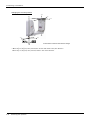
1) Please prepare the following: Leakage current breaker (with the terminal cover), cable for connecting the
primary power supply (AWG #14 (2mm2 or above), cables to ground the primary power supply (AWG #12
(3.5mm2 or above).
The secondary power cable (with the ACIN connector) for single phase or three phase power is supplied with
the product to match the specifications. When you build a cable suitable for your environment using the ACIN
connector and the ACIN terminal supplied, prepare a secondary power cable (AWG #14 (2mm2) or above).
2) Confirm that the primary power matches the specifications.
3) Confirm that the primary power is OFF and that the earth leakage breaker power switch is OFF.
4) Connect the secondary power cable.
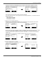
a) When using the supplied power cable with the ACIN connector
Refer to the figure above and connect the cable from the secondary side of the earth leakage breaker.
b) When building a power cable using the ACIN connector and the ACIN terminals supplied
Connect the ACIN terminals with the secondary power cable (prepared by customers), and insert the ACIN
terminals to the ACIN connector pins with the following numbers. Crimping caulking is recommended to
connect the ACIN terminals.
For single phase: 1 and 3
For three phase: 1, 2, and 3
Refer to the figure above and connect the cable from the secondary side of the earth leakage breaker.
5) Connect this ACIN connector to the ACIN connector on the front of the controller.
6) Connect the grounding cable to the PE terminal. (M4 screw)
7) Connect the primary power cable to the primary side terminal of the earth leakage breaker.
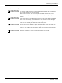
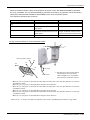
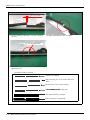
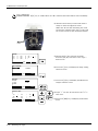
CAUTION
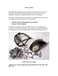
Be careful of interference with peripheral equipment.
Especially don't give a shock to the shaft (J3 axis). When you install the
hand, be careful not to knock at the shaft end by the hammer etc. The shaft
may be damaged.
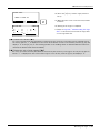
Take care also of the following items.
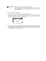
(1)The robot's locus of movement may change with specified speed.
Especially as for the corner section, short cut distance may change. Therefore, when beginning automatic operation, moves at low speed at first, and you should gather speed slowly with
being careful of interference with peripheral equipment.
Short cut
Arch movement (example)
(2)It can be confirmed whether the specified position exist in the defined area by using the instruction command "Zone". It can utilize as one of the methods for collision evasion. Refer to the
"detailed description of the instructions manual/function, and operation" of the separate volume
for the details of the instruction command.
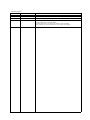
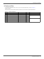
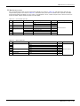
Revision history
Date of Point
Instruction Manual No.
Revision Details
2014-08-09
BFP-A3335
・ First print
2014-08-22
BFP-A3335-A
・ Recommended grease gun was described.
2015-02-10
BFP-A3335-B
・ The explanation of the origin setting method were added. The description of the setting
range of ABS origin method was added.
・ The description of how to change the operating range was added.
・ The corporate logo mark of illustrations in this manual was changed.
*Introduction
Thank you for purchasing the Mitsubishi industrial robot.
This instruction manual explains the method of unpacking, installation and maintenance and inspection of
the robot arm.
Always read through this manual before starting use to ensure correct usage of the robot.
The information contained in this document has been written to be accurate as much as possible. Please
interpret that items not described in this document "cannot be performed."
And, when maintenance and inspection of the robot, to access the arm and the base section is necessary.
Please prepare the environment which can access the robot with the stepladder etc. in RH-3FHR.
This document explains for the following robot type.
Robot type
・ RH-1FHR series
・ No part of this manual may be reproduced by any means or in any form, without prior consent from
Mitsubishi.
・ The details of this manual are subject to change without notice.
・ The information contained in this document has been written to be accurate as much as possible.
Please interpret that items not described in this document "cannot be performed." or "alarm may
occur".
Please contact your nearest dealer if you find any doubtful, wrong or skipped point.
・ This specifications is original.
・ Company names and production names in this document are the trademarks or registered trademarks
of their respective owners.
Copyright(C) 2014-2015 MITSUBISHI ELECTRIC CORPORATION
CONTENTS
Page
1 Before starting use ..........................................................................................................................
1.1 Using the instruction manuals ...................................................................................................
1.1.1 The details of each instruction manuals ...............................................................................
1.1.2 Symbols used in instruction manual ....................................................................................
1.2 Safety Precautions ....................................................................................................................
1.2.1 Precautions given in the separate Safety Manual ................................................................
1-1
1-1
1-1
1-2
1-3
1-4
2 Unpacking to Installation .............................................................................................................................................................. 2-6
2.1 Confirming the product ......................................................................................................................................................... 2-6
2.2 Installation .................................................................................................................................................................................. 2-7
2.2.1 Unpacking ............................................................................................................................................................................ 2-7
2.2.2 Transportation procedures .......................................................................................................................................... 2-8
(1) Transporting with a crane ........................................................................................................................................ 2-8
(2) Transporting with a manual pallet jack ............................................................................................................... 2-9
2.2.3 Installation procedures ................................................................................................................................................ 2-10
2.2.4 Grounding procedures .................................................................................................................................................. 2-12
(1) Grounding methods ................................................................................................................................................... 2-12
(2) Grounding procedures ............................................................................................................................................. 2-12
2.2.5 Connecting with the controller ................................................................................................................................ 2-13
(1) CR750 controller ....................................................................................................................................................... 2-13
(2) CR751 controller ....................................................................................................................................................... 2-15
2.2.6 Ethernet Cables .............................................................................................................................................................. 2-17
(1) No.2 arm ........................................................................................................................................................................ 2-17
(2) Base area ...................................................................................................................................................................... 2-18
2.2.7 Passing air hoses and cables through the shaft ............................................................................................... 2-20
(1) Specifications of internal air hoses and cables ............................................................................................ 2-20
(2) Customer prepared products ............................................................................................................................... 2-20
(3) Installation procedure .............................................................................................................................................. 2-21
2.3 Setting the origin ................................................................................................................................................................... 2-23
2.3.1 Installing the teaching pendant (T/B) ................................................................................................................... 2-23
(1) CR750 controller ....................................................................................................................................................... 2-23
(2) CR751 controller ....................................................................................................................................................... 2-24
2.3.2 Setting the origin with the origin data input method ...................................................................................... 2-25
(1) Confirming the origin data ..................................................................................................................................... 2-25
(2) Turning ON the control power ............................................................................................................................. 2-25
(3) Preparing the T/B ..................................................................................................................................................... 2-26
(4) Selecting the origin setting method ................................................................................................................... 2-27
(5) Inputting the origin data ......................................................................................................................................... 2-28
(6) Installing the battery cover. .................................................................................................................................. 2-29
2.4 Confirming the operation .................................................................................................................................................... 2-30
(1) JOINT jog operation ................................................................................................................................................. 2-34
(2) XYZ jog operation ...................................................................................................................................................... 2-36
(3) TOOL jog operation .................................................................................................................................................. 2-38
(4) 3-axis XYZ jog operation ....................................................................................................................................... 2-40
(5) CYLNDER jog operation ......................................................................................................................................... 2-42
(6) Work jog operation ......................................................................................................... 2-44
3 Installing the option devices .....................................................................................................................................................
3.1 Installing the solenoid valve set ......................................................................................................................................
(1) Hand number and solenoid valve ports (common to RH-FH series) ...................................................
3.2 Installing the hand input cable .........................................................................................................................................
3.3 Installing the hand output cable ......................................................................................................................................
3.4 Changing the operating range ..........................................................................................................................................
(1) Operating range changeable angle .....................................................................................................................
(2) The change method of the operating range ...................................................................................................
3.5 Hand internal wiring and piping set ................................................................................................................................
i
3-51
3-51
3-52
3-53
3-54
3-55
3-55
3-56
3-57
CONTENTS
Page
(1) Installation procedure .............................................................................................................................................. 3-57
3.6 External Wiring and Piping Box ........................................................................................................................................ 3-60
3.7 Installing the vacuum valve set ....................................................................................................................................... 3-63
4 Basic operations ............................................................................................................................................................................ 4-65
5 Maintenance and Inspection ..................................................................................................................................................... 5-66
5.1 Maintenance and inspection interval ............................................................................................................................. 5-66
5.2 Inspection items ..................................................................................................................................................................... 5-67
5.2.1 Daily inspection items .................................................................................................................................................. 5-67
5.2.2 Periodic inspection ........................................................................................................................................................ 5-68
5.3 Maintenance and inspection procedures ..................................................................................................................... 5-69
5.3.1 Robot arm structure ..................................................................................................................................................... 5-69
5.3.2 Installing/removing the cover ................................................................................................................................... 5-70
5.3.3 Packing Replacement Procedure ............................................................................................................................ 5-71
(1) Packing Replacement Instructions ..................................................................................................................... 5-71
5.3.4 Inspection, maintenance and replacement of timing belt .............................................................................. 5-75
(1) Timing belt replacement period ......................................................................................................................... 5-75
(2) Inspecting/Adjusting the J3 axis timing belt ................................................................................................. 5-76
(3) Replacing the J3 axis timing belt ........................................................................................................................ 5-77
(4) Inspecting/Adjusting the J4 axis timing belt ................................................................................................. 5-80
(5) Timing belt tension ................................................................................................................................................... 5-83
5.3.5 Replacing the bellows (Option) ................................................................................................................................ 5-84
5.3.6 Lubrication ........................................................................................................................................................................ 5-85
(1) Lubrication position and specifications ............................................................................................................ 5-85
(2) Lubrication method to the J1, J2 axis ............................................................................................................. 5-86
(3) Lubrication method to the shaft ......................................................................................................................... 5-86
5.3.7 Replacing the backup battery ................................................................................................................................... 5-87
(1) Replacing the battery (robot arm) ...................................................................................................................... 5-88
5.4 About Overhaul ...................................................................................................................................................................... 5-89
5.5 Maintenance parts ................................................................................................................................................................. 5-90
5.6 Resetting the origin .............................................................................................................................................................. 5-91
5.6.1 Mechanical stopper method ...................................................................................................................................... 5-92
(1) J1 axis origin setting (mechanical stopper) ................................................................................................... 5-92
(2) J2 axis origin setting (mechanical stopper) ................................................................................................... 5-94
(3) J3 and J4 axis origin setting (mechanical stopper) .................................................................................... 5-96
5.6.2 Jig method ........................................................................................................................................................................ 5-99
(1) J1 axis origin setting ............................................................................................................................................. 5-100
(2) J2 axis origin setting ............................................................................................................................................. 5-102
(3) J3 and J4 axis origin setting ............................................................................................................................. 5-103
5.6.3 ABS origin method ..................................................................................................................................................... 5-104
(1) Select the T/B ........................................................................................................................................................ 5-105
5.6.4 User origin method ..................................................................................................................................................... 5-107
5.6.5 Recording the origin data ........................................................................................................................................ 5-109
(1) Confirming the origin data label ........................................................................................................................ 5-109
(2) Confirming the origin data .................................................................................................................................. 5-109
(3) Recording the origin data .................................................................................................................................... 5-109
(4) Installing the battery cover ................................................................................................................................ 5-109
6Appendix ............................................................................................................................................................................ Appendix-110
Appendix 1 : Configuration flag .......................................................................................................................... Appendix-110
ii
1Before starting use
1 Before starting use
This chapter explains the details and usage methods of the instruction manuals, the basic terminology and
the safety precautions. Moreover, handling and operation of a teaching pendant (T/B) are described based
on R32TB (R33TB) in instruction manuals. If using other T/B, such as R56TB (R57TB), refer to a supplied
instruction manual of the T/B.
1.1 Using the instruction manuals
1.1.1 The details of each instruction manuals
The contents and purposes of the documents enclosed with this product are shown below. Use these documents according to the application.
For special specifications, a separate instruction manual describing the special section may be enclosed.
Safety Manual
Explains the common precautions and safety measures to be taken for robot handling, system design and manufacture to ensure safety of the operators involved with the robot.
Special
Specifications
Explains the product's standard specifications, factory-set special specifications, option
configuration and maintenance parts, etc. Precautions for safety and technology, when
incorporating the robot, are also explained.
Robot Arm
Setup &
Maintenance
Explains the procedures required to operate the robot arm (unpacking, transportation,
installation, confirmation of operation), and the maintenance and inspection procedures.
Controller
Setup, Basic
Operation and
Maintenance
Detailed
Explanation of
Functions and
Operations
Troubleshooting
Additional axis function
Tracking Function Manual
Extended
Function
Instruction
Manual
Explains the procedures required to operate the controller (unpacking, transportation,
installation, confirmation of operation), basic operation from creating the program to automatic operation, and the maintenance and inspection procedures.
Explains details on the functions and operations such as each function and operation, commands used in the program, connection with the external input/output device, and parameters, etc.
Explains the causes and remedies to be taken when an error occurs. Explanations are given
for each error No.
Explains the specifications, functions and operations of the additional axis control.
Explains the control function and specifications of conveyor tracking
Explains the detailed description of data configuration of shared memory, monitoring, and
operating procedures, about the PLC(CR750-Q/CR751-Q controller) and the GOT(CR750D/CR751-D controller).
1-1 Using the instruction manuals
1Before starting use
1.1.2 Symbols used in instruction manual
The symbols and expressions shown in Table 1-1 are used throughout this instruction manual. Learn the
meaning of these symbols before reading this instruction manual.
Table 1-1:Symbols in instruction manual
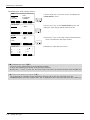
Terminology
Item/Symbol
Meaning
iQ Platform
Controller
Indicates the controller which controls the robot arm.
It consists of the robot CPU system and the drive unit.
The robot CPU unit or robot CPU
Indicates the CPU unit for the robots which installed to the sequencer
base unit (Q3 □ DB) of MELSEC-Q series. It is connected with the
drive unit by the dedicated cable.
The robot CPU system
Multi-CPU system.
It consists of MELSEC units, such as the sequencer base unit, the
sequencer CPU unit, and the robot CPU unit, etc.
Drive unit
Indicates the box which mounts the servo amplifier for robot, and the
safety circuit, etc.
Item
Stand-alone type
Item
Symbol
Indicates the box which arranged control parts, such as robot CPU,
servo amplifier, and the safety circuit.
Controller
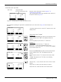
DANGER
WARNING
CAUTION
Precaution indicating cases where there is a risk of operator fatality or
serious injury if handling is mistaken. Always observe these precautions to safely use the robot.
Precaution indicating cases where the operator could be subject to
fatalities or serious injuries if handling is mistaken. Always observe
these precautions to safely use the robot.
Precaution indicating cases where operator could be subject to injury
or physical damage could occur if handling is mistaken. Always
observe these precautions to safely use the robot.
[JOG]
If a word is enclosed in brackets or a box in the text, this refers to a
key on the teaching pendant.
[RESET] + [EXE]
(A)
(B)
This indicates to press the (B) key while holding down the (A) key.
In this example, the [RESET] key is pressed while holding down the
[EXE] key.
T/B
This indicates the teaching pendant.
O/P
Indicates the operating panel on the front of controller or drive unit for
the controller which installed the operating panel
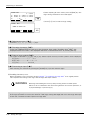
CR751 (Thin type)
CR751 (Heavy type)
There are two kinds of CR751 controller; one is "Thin type" (the
height is 98mm) and the other is "Heavy type" (the height is 174mm),
each of which are different in height.
Thin type: CR751-03HD/Q, CR751-06HD/Q, CR751-12HD/Q,
CR751-20HD/Q, CR751-03HRD/Q, CR751-02VD/Q,
CR751-04VD/Q, CR751-04VJD/Q, CR751-07VD/Q.
Heavy type: CR751-13VD/Q, CR751-20VD/Q, CR751-07VLD/Q.
* Refer to separate Standard Specifications Manual for the outside
dimension of CR751 controller.
Using the instruction manuals 1-2
1Before starting use
1.2 Safety Precautions
Always read the following precautions and the separate "Safety Manual" before starting use of the robot to
learn the required measures to be taken.
CAUTION
CAUTION
WARNING
CAUTION
DANGER
CAUTION
CAUTION
CAUTION
1-3 Safety Precautions
All teaching work must be carried out by an operator who has received special
training. (This also applies to maintenance work with the power source turned ON.)
Enforcement of safety training
For teaching work, prepare a work plan related to the methods and procedures of
operating the robot, and to the measures to be taken when an error occurs or when
restarting. Carry out work following this plan. (This also applies to maintenance
work with the power source turned ON.)
Preparation of work plan
Prepare a device that allows operation to be stopped immediately during teaching
work. (This also applies to maintenance work with the power source turned ON.)
Setting of emergency stop switch
During teaching work, place a sign indicating that teaching work is in progress on
the start switch, etc. (This also applies to maintenance work with the power source
turned ON.)
Indication of teaching work in progress
Provide a fence or enclosure during operation to prevent contact of the operator
and robot.
Installation of safety fence
Establish a set signaling method to the related operators for starting work, and follow this method.
Signaling of operation start
As a principle turn the power OFF during maintenance work. Place a sign indicating that maintenance work is in progress on the start switch, etc.
Indication of maintenance work in progress
Before starting work, inspect the robot, emergency stop switch and other related
devices, etc., and confirm that there are no errors.
Inspection before starting work
1Before starting use
1.2.1 Precautions given in the separate Safety Manual
The points of the precautions given in the separate "Safety Manual" are given below.
Refer to the actual "Safety Manual" for details.
DANGER
CAUTION
CAUTION
CAUTION
CAUTION
CAUTION
CAUTION
WARNING
WARNING
CAUTION
WARNING
CAUTION
CAUTION
CAUTION
CAUTION
WARNING
When automatic operation of the robot is performed using multiple control devices
(GOT, programmable controller, push-button switch), the interlocking of operation
rights of the devices, etc. must be designed by the customer.
Use the robot within the environment given in the specifications. Failure to do so
could lead to a drop or reliability or faults. (Temperature, humidity, atmosphere,
noise environment, etc.)
Transport the robot with the designated transportation posture. Transporting the
robot in a non-designated posture could lead to personal injuries or faults from
dropping.
Always use the robot installed on a secure table. Use in an instable posture could
lead to positional deviation and vibration.
Wire the cable as far away from noise sources as possible. If placed near a noise
source, positional deviation or malfunction could occur.
Do not apply excessive force on the connector or excessively bend the cable.
Failure to observe this could lead to contact defects or wire breakage.
Make sure that the workpiece weight, including the hand, does not exceed the
rated load or tolerable torque. Exceeding these values could lead to alarms or
faults.
Securely install the hand and tool, and securely grasp the workpiece. Failure to
observe this could lead to personal injuries or damage if the object comes off or
flies off during operation.
Securely ground the robot and controller. Failure to observe this could lead to
malfunctioning by noise or to electric shock accidents.
Indicate the operation state during robot operation. Failure to indicate the state
could lead to operators approaching the robot or to incorrect operation.
When carrying out teaching work in the robot's movement range, always secure
the priority right for the robot control. Failure to observe this could lead to personal
injuries or damage if the robot is started with external commands.
Keep the jog speed as low as possible, and always watch the robot. Failure to do
so could lead to interference with the workpiece or peripheral devices.
After editing the program, always confirm the operation with step operation before
starting automatic operation. Failure to do so could lead to interference with
peripheral devices because of programming mistakes, etc.
Make sure that if the safety fence entrance door is opened during automatic operation, the door is locked or that the robot will automatically stop. Failure to do so
could lead to personal injuries.
Never carry out modifications based on personal judgments, or use non-designated maintenance parts.
Failure to observe this could lead to faults or failures.
When the robot arm has to be moved by hand from an external area, do not place
hands or fingers in the openings. Failure to observe this could lead to hands or fingers catching depending on the posture.
Safety Precautions 1-4
1Before starting use
CAUTION
CAUTION
CAUTION
DANGER
DANGER
DANGER
DANGER
CAUTION
CAUTION
1-5 Safety Precautions
Do not stop the robot or apply emergency stop by turning the robot controller's
main power OFF.
If the robot controller main power is turned OFF during automatic operation, the
robot accuracy could be adversely affected.
Do not turn off the main power to the robot controller while rewriting the internal
information of the robot controller such as the program or parameters. If the main
power to the robot controller is turned off while in automatic operation or rewriting
the program or parameters, the internal information of the robot controller may be
damaged.
Do not connect the Handy GOT when using the GOT direct connection function of
this product. Failure to observe this may result in property damage or bodily injury
because the Handy GOT can automatically operate the robot regardless of
whether the operation rights are enabled or not.
Do not connect the Handy GOT to a programmable controller when using an iQ
Platform compatible product with the CR750-Q/CR751-Q controller. Failure to
observe this may result in property damage or bodily injury because the Handy
GOT can automatically operate the robot regardless of whether the operation rights
are enabled or not.
Do not remove the SSCNET III cable while power is supplied to the multiple CPU
system or the servo amplifier. Do not look directly at light emitted from the tip of
SSCNET III connectors or SSCNET III cables of the Motion CPU or the servo
amplifier. Eye discomfort may be felt if exposed to the light. (Reference: SSCNET
III employs a Class 1 or equivalent light source as specified in JIS C 6802 and
IEC60825-1 (domestic standards in Japan).)
Do not remove the SSCNET III cable while power is supplied to the controller. Do
not look directly at light emitted from the tip of SSCNET III connectors or SSCNET
III cables. Eye discomfort may be felt if exposed to the light. (Reference: SSCNET
III employs a Class 1 or equivalent light source as specified in JIS C 6802 and
IEC60825-1 (domestic standards in Japan).)
Attach the cap to the SSCNET III connector after disconnecting the SSCNET III
cable. If the cap is not attached, dirt or dust may adhere to the connector pins,
resulting in deterioration connector properties, and leading to malfunction.
Make sure there are no mistakes in the wiring. Connecting differently to the way
specified in the manual can result in failures, such as the emergency stop not
being released. In order to prevent from occurring, please be sure to check that all
functions (such as the teaching box emergency stop, customer emergency stop,
and door switch) are working properly after the wiring setup is completed
Use the network equipments (personal computer, USB hub, LAN hub, etc) confirmed by manufacturer. The thing unsuitable for the FA environment (related with
conformity, temperature or noise) exists in the equipments connected to USB.
When using network equipment, measures against the noise, such as measures
against EMI and the addition of the ferrite core, may be necessary. Please fully
confirm the operation by customer. Guarantee and maintenance of the equipment
on the market (usual office automation equipment) cannot be performed.
2Unpacking to Installation
2 Unpacking to Installation
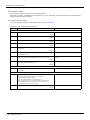
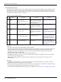
2.1 Confirming the product
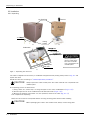
The standard configuration of the robot arm, part of the purchased product, is shown in Table 2-1.
Confirm the parts.
Users who have purchased optional products should refer to the separate "Special Specifications".
Table 2-1 : Standard configuration
No.
Part name
Type
RH-1FHR series
Qty.
1
Robot arm
2
Guarantee card
3
Installation bolts
M12 x 45
4 pcs.
4
Spring washer for installation bolts
For M12
4 pcs.
5
Plain washer for installation bolts
For M12
6
Fixing plate
1 set
7
Fixing plate installation bolt
1 set
8
Transportation tool
1 set
9
Transportation tool installation bolt
1 set
Remarks
1 unit
1 copy
For robot arm installation
4 pcs.
For robot arm transportation
Confirming the product 2-6
2Unpacking to Installation
2.2 Installation
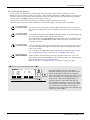
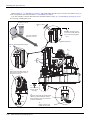
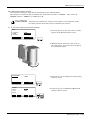
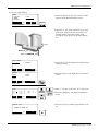
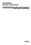
2.2.1 Unpacking
<2> ②上ブタ
Upper lid
Pull out
引き抜く
<1>①テープ
Tape
Fixing
board
固定台
(a)
(b)
Robot arm
ロボット本体
Fixing
固定具plate
<3> Hexagon
socket bolts
③六角穴付ボルト
(Four
positions)
(4箇所)
!
CAUTION
!
Transportation
tool
運搬治具
Always unpack the
robot at a flat place.
The robot could tilt
over if unpacked at an
unstable place.
(c)
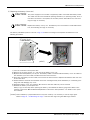
Fig.2-1 : Unpacking the robot arm
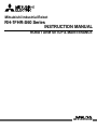
The robot is shipped from the factory in cardboard and plywood frame packing. Always refer to Fig. 2-1 and
unpack the robot.
Handle the robot arm according to "2.2.2Transportation procedures".
CAUTION
Always unpack the robot at a flat place. The robot could tilt over if unpacked at an
unstable place.
The unpacking process is shown below.
1) Using a knife, etc., slit the tape <1> fixing the upper lid <2> of the cardboard box. (Fig. 2-1 (a))
2) Pull the upper lid <2> of the cardboard box off with both hands. (Fig. 2-1 (b))
3) Remove the hexagon socket bolts <3> (four positions) which fix the robot. (Fig. 2-1 (c))
This completes the unpacking.
Note) The robot must be transported without removing the fixing plate. Remove after installing.
CAUTION
2-7 Installation
When repackaging the robot in the wooden frame, always use the fixing plate.
2Unpacking to Installation
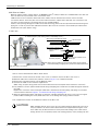
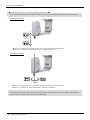
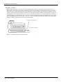
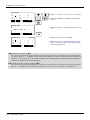
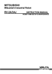
2.2.2 Transportation procedures
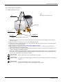
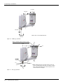
(1) Transporting with a crane
Mass
RH-1FHR series: Approx. 56kg
Wire
Fixing plate
Wire hook
Transportation tool
Eye bolt
Fig.2-2 : Transportation of robot arm
1) Hook the wires to each of the four eyebolts attached to the transportation tool. (Make sure the bolts are
securely hooked.)
2) Lift with a crane to transport the robot to the designated location.
3) At this time, make sure that the wires, etc., do not interfere with the robot arm or the covers. Always place
the cloth, etc., at interfering places.
4) Be careful not to subject the robot to physical shock during transport.
5) After installing the robot (refer to Page 10, "2.2.3 Installation procedures"), remove the wires, the wire
hooks, transportation tool and fixing plate.
6) Always follow the above procedures and methods to transport the robot for secondary transportation, such
as when changing the installation position.
If the arm is directly suspended without using the specified transportation tool, or if it is suspended in the
work posture, the configuration devices could be damaged, and the transportation workers will be subject to
risk due to an inadequate center of gravity position.
CAUTION
CAUTION
CAUTION
When transporting a robot, always attach four wires.
To reattach the fixing plate again, set the axes of the robot to the positions according to
Table 2-2.
The robot should keep vertical. (not be horizontal)
It becomes the cause of the grease leakage or the trouble.
Installation 2-8
2Unpacking to Installation
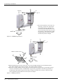
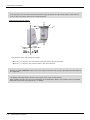
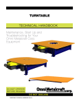
(2) Transporting with a manual pallet jack
Mass
RH-1FHR series: Approx. 56kg
Fixing plate
A
Transportation
tool
B
Forks
<Fork insertion segment>
View A
View B
Fork insertion segment
Fig.2-3 : Transportation of robot arm
1)
2)
3)
4)
Insert the forks of a manual pallet jack surely into the fork insertion segment of the transportation tool.
Lift up the robot with a manual pallet jack to transport it to the designated location.
Be careful not to subject the robot to physical shock during transport.
After installing the robot (refer to Page 10, "2.2.3 Installation procedures"), pull out the forks and remove
the transportation tool and fixing plate.
5) Always follow the above procedures and methods to transport the robot for secondary transportation, such
as when changing the installation position.
If the arm is directly lift up without using the specified transportation tool, or if it is lifted up in the work
posture, the configuration devices could be damaged, and the transportation workers will be subject to risk
due to an inadequate center of gravity position.
CAUTION
CAUTION
To reattach the fixing plate again, set the axes of the robot to the positions according to
Table 2-2.
The robot should keep vertical. (not be horizontal)
It becomes the cause of the grease leakage or the trouble.
Table 2-2 : Transportation posture
Axis
Posture
J1
0°
J2
145°
J3
-480mm
J4
Not fixed
2-9 Installation
2Unpacking to Installation
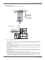
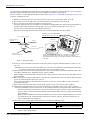
2.2.3 Installation procedures
The installation procedure of the robot arm is shown below.
FV
FH
ML
FH
FH
25
FH
ML
Plain washer
平座金
Springバネ座金
washer
4-M12×45
(Four positions)
(4箇所)
MT
<Base bottom>
2-φ6 holes
2-φ6穴
(for
φ8 positioning pins)
(φ8位置決めピン用下穴)
refRz25 (Installation
erence surface)
(据付基準)
FV
4-φ
16 installation holes
4-φ16据付用穴
122
120
(158)
200
80
Rz25
200
200
220
240
242
122
(Installation reference
surface)
(据付基準)
280
Fig.2-4 : Installation dimensions
1) The robot installation surface has been machine finished. Use the installation holes (4-φ16 holes) opened
at the four corners of the base, and securely fix the robot with the enclosed installation bolts (hexagon
socket bolts).
2) Install the robot on a level surface.
3) It is recommended that the surface roughness of the table onto which the robot is to be installed by Rz25 or
more. If the installation surface is rough, the contact with the table will be poor, and positional deviation
could occur when the robot moves.
4) When installing, use a common table to prevent the position of the devices and jigs subject to robot work
from deviating.
5) The installation surface must have sufficient strength to withstand the arm reaction during operation, and
resistance against deformation and vibration caused by the static (dynamic) load of the robot arm and
peripheral devices, etc.
6) After installing the robot, remove the fixing plate and transportation tool.
7) If you operate the robot at a high speed, reaction forces are applied to the installation stand by the robot's
operation. Make sure that the installation stand on which the robot is placed has sufficient strength and
rigidity. Table 2-3 shows the maximum reaction force (design values) that may be applied to an installation
stand. Please use these values as reference when designing the installation stand.
Installation 2-10
2Unpacking to Installation
Table 2-3 : Magnitude of each reaction force
Tilt moment : ML
Torsional moment : MT
Horizontal direction translation force : FH
Vertical direction translation force : FV
CAUTION
CAUTION
Unit
Value
N・m
610
N・m
807
N
1,575
N
712
When installing the robot, secure following space.
・ Connection space for connecting machine cables behind the robot.
・ Maintenance space for replacing the batteries in front of the robot.
・ Maintenance space for removing No.2 arm cover above the robot.
And don't install the robot arm in the position where direct rays or the heat of lighting
hits. The skin temperature of the robot arm may rise, and the error may occur.
When leading machine cables, fix cables in the position near connectors as much as
possible not to apply excessive force or the cable's weight on the connectors.
Maintenance space
for removing No.2
arm cover.
Fix machine cables.
Connection space for
connecting the machine cable.
Maintenance space for
replacing the batteries.
CAUTION
2-11 Installation
This robot is hanging installation type. Do not put the robot in an inverted position. It
may cause oil leakage or faults.
2Unpacking to Installation
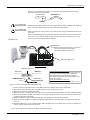
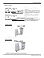
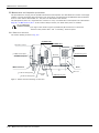
2.2.4 Grounding procedures
(1) Grounding methods
Robot arm
Controller
and
personal
computer
(a) Dedicated grounding
(Optimum)
Robot arm
Controller
and
personal
computer
(b) Common grounding
(Good)
Robot arm
Controller
and
personal
computer
(c) Common grounding
(Normal)
1) There are three grounding methods as shown in
Fig. 2-5, but the dedicated grounding (Fig. 2-5 (a))
should be used for the robot arm and controller
when possible. (Refer to the separate " Controller
Setup, Basic Operation and Maintenance" for
details on the controller grounding.)
2) Use Class D grounding (grounding resistance
100Ω or less).
Dedicated grounding separated from the other
devices should be used.
3) Use a AWG#11(4.2mm2) or more stranded wire for
the grounding wire. The grounding point should be
as close to the robot arm and controller as possible, and the length of the grounding wire should
be short.
Fig.2-5 : Grounding methods
(2) Grounding procedures
2
Robot grounding cable(AWG
(AWG#11
(4.2mm2)
or more)
本体接地用ケーブル
#11(3.5mm
)以上)
(Prepared by customer)
(お客様にてご手配ください)
A
1) Prepare the grounding cable (AWG#11(4.2mm2) or
more) and robot side installation screw and washer.
2) If there is rust or paint on the grounding screw section (A), remove it with a file, etc.
3) Connect the grounding cable to the grounding screw
section.
Plain
washer
平座金
Spring
washer
ばね座金
M4×10
Fig.2-6 : Connecting the grounding cable
Installation 2-12
2Unpacking to Installation
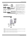
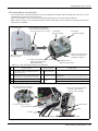
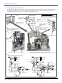
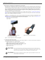
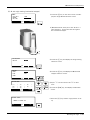
2.2.5 Connecting with the controller
(1) CR750 controller
Note1)
Controller
コントローラ
Motor
power
モータパワー
(CN1)
Motor
signal
モータ信号
(CN2)
Latch
ラッチ
CN1
CN2
CN2
Motor
signal cable
モータ信号ケーブル
CN1
Latch
ラッチ
Robot
arm base section
ロボット本体ベース部
Motor
power cable
モータ電源ケーブル
Note 1) Although the picture is the CR750-D controller, also the connection method is the same in the CR750-Q controller
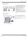
Fig.2-7 : Connecting the machine cables
Carry out the following procedure after installing the controller referring to the separate "Controller Setup, Basic
Operation and Maintenance" manual.
Robot arm
ロボット本体
1) Make sure that the power switch on the front of the
controller is turned OFF.
Connector on the
robot arm side
ロボット本体側コネクタ
2) Connect the machine cable to its corresponding connector
on the robot arm side.
Hook
固定フック
Projection
突起部
Connector on the
machine cable side
機器間ケーブル側コネクタ
3) After connecting the connector, insert the hook attached
to the connector on the machine cable side to the rear of
the projection of the robot arm connector to fix securely in
place.
Hook
固定フック
Projection
突起部
CAUTION
Be careful not to get your hand
pinched.
This complete the connection of machine cable.
2-13 Installation
2Unpacking to Installation
To remove the cable, insert a minus screwdriver into the hook
while padding with a cloth, and remove the cable by lifting the
hook.
Hook
Projection
Minus screwdriver
CAUTION
Padding
CAUTION
CAUTION
CAUTION
CAUTION
When installing or removing the connector, to the connector
of the other party in parallel, install or remove. If load strong
against one side is applied, the connector pin may be
damaged and it may not be connected securely.
The machine cable connectors are dedicated for the controller side and robot arm
side, so take special care when connecting.
If connected incorrectly, the connector pins could bend or break. Thus, even if
connected correctly, the robot will not operate correctly, creating a dangerous
situation.
Take special care to the leading of the connection cable. If the cable is pulled with
force or bent excessively, wires could break or the connector could be damaged.
Connect the machine cable at the place without the effect of the dust or oil mist.
Please keep the dust and oil mist from being applied to of the robot-arm connector
section, in the condition that the machine cable is removed. Since it becomes the
cause of failure.
Please be careful not to catch the hand at installation and removal.
Installation 2-14
2Unpacking to Installation
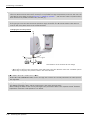
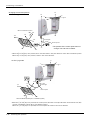
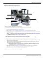
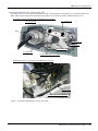
(2) CR751 controller
Robot
arm base section
ロボット本体ベース部
Controller
コントローラ
Motor
power (CN1)
モータ電源(CN1)
Note1)
Motor
signal (CN2)
モータ信号(CN2)
AMP1 AMP2 BRK
ネジ
Two(固定用
fixing screws
2本)
CN2
CN1
CONBOX cover
ネジ
Two fixing screws
(固定用 2本)
Motor signal cable
モータ信号ケーブル
Note 1) Although the picture is the CR751-D controller, also the connection method is the same in the CR751-Q controller.
Motor power cable
モータ電源ケーブル
The cables are passed
into the opening
Hollow
Cable clamp fixing plate
The each boards are fixed in the condition of
having been inserted in the hollow.
CN2
AMP2
AMP1
Machine cable
Controller side
Robot arm side
Cable clamp fixing
plate
(two plates)
Fig.2-8 : Connecting the machine cables
Install a controller while referring to "Installation procedures" in the separate "Controller setup, basic operation,
and maintenance" manual and attach a cable fixation plate referring to "Attachments installation procedures".
Then connect a robot arm and controller with machine cables. The procedure of connecting the machine cable is
shown below.
1) Make sure that the power switch of the controller is turned OFF.
2) Connect the machine cable to its corresponding connector on the robot arm side.
a) Refer to Page 70, "5.3.2 Installing/removing the cover", and remove the CONBOX cover.
b) Feed the connector of robot side to the opening on the back of the robot base.
c) Insert the cable clamp fixing plate attached to the machine cable into the hollow just under the opening.
Fixing the plate by two screws securely under the condition that the plates inserted into the hollow.
d) Connect the machine cable to its corresponding connector on the robot arm side. Connect the connector
(AMP1, AMP2, CN2) securely.
e) Install the CONBOX cover securely as before.
3) Connect the machine cable to the corresponding connector of the controller. Connects the connector CN1
(AMP1, AMP2, BRK) and CN2 surely. Fix CN2 connector by tightening two screws. Tighten the fixing screw
of CN2 by 0.06-0.07 Nm.
2-15 Installation
2Unpacking to Installation
This completes connecting the machine cables.
CAUTION
CAUTION
CAUTION
CAUTION
The machine cable connectors are dedicated for the controller side and robot arm
side, so take special care when connecting.
If connected incorrectly, the connector pins could bend or break. Thus, even if
connected correctly, the robot will not operate correctly, creating a dangerous
situation.
Take special care to the leading of the connection cable. If the cable is pulled with
force or bent excessively, wires could break or the connector could be damaged.
In order to prevent a breaking of cables and a damage of connectors, always use the
controller after installing the attachment cable fixation plate.
Connect the machine cable at the place without the effect of the dust or oil mist.
Please keep the dust and oil mist from being applied to of the robot-arm connector
section, in the condition that the machine cable is removed. Since it becomes the
cause of failure.
Please be careful not to catch the hand at installation and removal.
Installation 2-16
2Unpacking to Installation
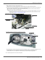
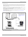
2.2.6 Ethernet Cables
Ethernet cables (4 pairs, totaling 8 lines, of AWG#26 (0.13mm2) cabtyre cables) are installed within the robot arm
from the base unit up to the No. 2 arm, and can be used.
LAN connectors are mounted to both ends of the cables, and can therefore be used to connect to LAN
connection devices. Users may also remove the LAN connectors, replace them with their own connectors, and
use them as spare wiring by connecting them to user supplied cables.
Further, when passing through the inside of the shaft and using, please use the optional hand internal wiring and
piping set in order to prevent the cable disconnection. (Re-cover the connector of the hand input cable that is
attached to this option before using)
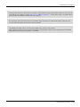
(1) No.2 arm
<a> Ethernet cable: 4 pairs, totaling 8 lines, of AWG#26(0.13mm2)
When using as the Ethernet cable
Customer prepared
Shaft
LAN connector
Robot side
When using as spare wiring
Cut the LAN connectors
Customer prepared
Connect the customer's conRobot side
Note) When using by passing through the shaft, please use the optional
hand internal wiring and piping set to prevent the cable disconnection.
Note) The robot is an example.
Fig.2-9 : Pulling out the Ethernet cable
How to connect the Ethernet cable is shown below.
1) Remove the screws used to fix the No. 2 arm cover U, and then remove the No. 2 arm cover U.
2) Ethernet cables are located in the positions shown in Fig. 2-9 <a> (coiled and stored).
3) Remove the tying band used to coil the Ethernet cable.
4) Connect the cable on the customer supplied tool.
(When using as spare wiring please remove the LAN connectors and replace with customer's connector)
5) It is possible to use the optional hand internal wiring and piping set to feed the tool cable through the inside of
the shaft.
Replace the connector of the hand input cable that is attached to the hand wiring and piping set, and then
connect. Please reference Page 57, "3.5 Hand internal wiring and piping set".
6) After the optional hand wiring and piping set has been installed, install the No. 2 arm cover U to its original
position. When installing the cover please take care not to damage the spongy sealant material.
This completed connection of the Ethernet cables on the No. 2 arm.
CAUTION
2-17 Installation
When installing the No. 2 arm cover U to its original position please take care not to
trap any cables or air hoses. If the cables/hoses are trapped when fixing the cover
then cables may be disconnected or hoses punctured, leading to the robot and air
driving devices to not operate properly. The sealing property of the packing may also
2Unpacking to Installation
become seriously impaired and there is a risk that the specified level of product
protection may not be achievable.
Normal
condition
正常な状態
abnormal
condition
折れた状態
Air hose
エアホース
CAUTION
CAUTION
When fixing the cable, please keep too much load from being applied to the cables. If
too much load is applied, the may break, when the robot moves.
When operating the robot, friction may result in dust being generated from the tip of
the shaft.
When an optional bellows set has been installed to the robot and then required cleanliness, be sure to seal the shaft tip with a gasket. If this is not done there is a risk
that the level of cleanliness will be reduced.
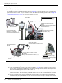
(2) Base area
Ethernet cable
Expansion
Fix the Ethernet cable to the ADD cover by cable clamp.
* The recommendation the cable clamp
OA-W1608 (OHM ELECTRIC INC.)
Inside the ADD cover
Base section rear
Inside
the robot arm
ロボットアーム内へ
ADD cover
ADDカバー
Ethernet cable
イーサネットケーブル
Lock
nut
ロックナット
Cable clamp
ケーブルクランプ
[Note]: Measures against the noise
If the communication error considered to originate by the
noise occurs, specify and remove the noise source.
And, implement the measures against the noise by
grounding of the Ethernet cable, and the addition of the
ferrite core if needed.
The recommendation the ferrite core
Type: E04SR301334 (SEIWA ELECTRIC MFG. CO., LTD.)
Fig.2-10 : Pull out the Ethernet cable (Base side)
1) Loosen the two screws and remove the ADD cover located at the back of the robot base.
2) Pull out the Ethernet cable that is stored inside the cover (coiled and stored).
3) Remove the cable tie of Ethernet cable.
4) Remove the lock nut attached to the cable clamp (customer prepared) and pass through the Ethernet cable
5) Remove the grommet of ADD cover. After removing the grommet please remove the sealant material that
remains in the hole in the plate.
6) Feed the Ethernet cable through the hole that was created by removing the grommet.
7) Feed the end of the Ethernet cable through the cable clamp and securely fasten the ADD cover with the
lock nut.
8) Install the ADD cover in its original position. When installing the cover please take care not to damage the
spongy sealing material stuck to the hole.
This completed pull out the Ethernet cables of the base section.
Installation 2-18
2Unpacking to Installation
CAUTION
CAUTION
CAUTION
CAUTION
2-19 Installation
Take care against applying big force to the Ethernet cable, other cables, and the air
hose.
Please confirm not having broken or not having stripped the packing when installing
or removing the cover. Contact to the dealer. Failure will be caused if the robot is
used under the condition that the packing is broken or stripped, because oil mist etc.
will invade in the arm.
When ADD cover is installed, please keep too much load from being applied to the
cables and the air hoses. If too much load is applied, the cable will be broken and the
hose is bent, therefore robot and pneumatic drive equipment cannot operate
normally.
When ADD cover is installed, catch neither the cable nor the air hose.
If the bolt is tightened while it had been caught, the cable will be broken and the hose
is bent, and the robot and pneumatic drive equipment cannot operate normally.
Moreover, packing does not stick securely and protection specification cannot be
secured.
2Unpacking to Installation
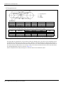
2.2.7 Passing air hoses and cables through the shaft
For this robot, customer prepared air hoses and cables can be pulled out from the No. 2 arm by passing through
the shaft. For how to pass air hoses and cables through the shaft, refer to the following.
(1) Specifications of internal air hoses and cables
Use the air hoses and the cables, which have flexibility, capability of being repeatedly bent and twisted, and high
wear resistance, for the internal use.
Select the air hose and the cable according to the specifications shown in Table 2-4.
Table 2-4 : Specifications of internal air hoses and cables
Model
RH-1FHR
Shaft inside
diameter
Space factor
(recommended)
φ11mm
50% or less
Highest speed of
J3 axis
1,100mm/sec
Minimum R of
bending
Operating angle of
J4 axis
20mm
±360deg
(2) Customer prepared products
Table 2-5 shows the necessary products for passing air hoses and cables through the shaft. The user needs to
prepare the products.
Table 2-5 : Customer prepared products
Name
Qty.
Usage and recommended product
Expanding sleeve
Moderate
quantity
Protecting the air hoses and cables, and improving the twisting rigidity
Recommended expanding sleeve: EXP-13-PT (manufactured by Kitagawa Industries Co.,
Ltd.)
Cushion rubber
Moderate
quantity
Protecting the bent portion and the fixed portion of the twisted end.
Recommended cushion rubber: silicon rubber, thickness of 1mm, dimensions of 30mm ×
80mm
Cable tie
Moderate
quantity
Fixing the air hoses and the cables
Silicon grease
Moderate
amount
Reducing friction and wear when the air hoses and the cables slide
Recommended silicon grease: G-501 (manufactured by Shin-Etsu Chemical Co., Ltd.)
Liquid gasket
Moderate
amount
Sealing the outlet at the tip of the shaft
Recommended liquid gasket: 1212 (manufactured by Three Bond Co., Ltd.)
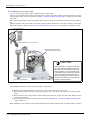
【Precautions for implementation of moving part】
1) The internal air hoses and cables are bent
and twisted according to the operations of
the J3 and J4 axes. Structurally, the
twisting occurs inside the shaft, and the
bending occurs inside the expanding sleeve.
Without the expanding sleeve, the twisted
air hoses and cables may run onto the guide
portion of the fixing plate, and the air hoses
may be bent or broken.
2) Do not place the connector connecting part
and the air hose relay part in the binding or
twisting range.
Bending range
Expanding sleeve
Plate for fixation
Twisting
range
Installation 2-20
2Unpacking to Installation
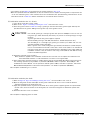
(3) Installation procedure
The installation procedure is shown below.
Refer to the installation diagram shown from the next section, and perform the installation correctly.
1) Move the J3 axis to the top end with a jog operation and shut off the controller's power supply. This is
necessary for space standard settings when feeding the air hose and hand input cable through the inside of
the shaft.
2) Remove the screws fixing the No. 2 arm cover U, and remove the No. 2 arm cover U.
3) Pass the tool (hand) side of the internal air hoses and cables through the shaft. Make sure that the air hoses
and the cables are not twisted or crossed.
4) Fix the air hoses and the cables with a cable tie so as to position the end of the expanding sleeve 10mm
away from the opening of the shaft.
5) The highest point of the curved section of the air hoses and cables should be matched up with the top of
the fixing plate.
CAUTION
If the air hoses and the cables are not long enough or too long, when the robot operates, excessive bending and friction with the shaft upper end or the cover may result
in a break or abnormal operations of the tool (hand).
6) In the state of the steps 4) and 5), fix the air hoses and the cables to the (a) and (b) portions of the plate
with cable ties. For the (a) portion, wrap the air hoses and the cables with cushion rubber before fixing.
7) When using the hand input signal or the optional solenoid valve, refer to Page 57, "3.5 Hand internal wiring
and piping set".
8) The connected connectors are stored to the (c) portion.
CAUTION
Do not remove the cable ties which fixing connectors.
Fix the plate on the No. 2 arm, other cables and air hoses with cable ties. In this way,
the internal cables and connectors do not touch the plate edge and others, or break
due to the vibration during the robot operation.
9) Carry out piping and wiring on the tool side.
Fix the air hoses and the cables, which are pulled out from the shaft lower end, to the hand side. Check
again that the highest point of the curved section of the air hoses and the cables reaches the height of the
fixing plate upper end, and then fix the air hoses and the cables at the outlet of the shaft.
When an optional bellows set has been installed to the robot and then required cleanliness, to ensure the
cleanliness level, use liquid gasket and others to seal the outlet on the shaft tip where the air hoses and
the cables are pulled out.
10) Apply silicon grease to the contact surface between the air hoses of the fixing plate and the cables, the
cable sliding portion from the shaft upper end to the fixed portion, and the opening on the shaft upper end.
11) Power on the controller, perform the jog operation for the J3 and J4 axes, and check that the air hoses
and the cables do not interfere with other components.
CAUTION
Do not power on the controller when the internal cables are connected to the connectors on the robot.
If the end of the cables on the tool side is not processed, troubles such as fuse blown
by ground fault or short circuit may occur. Check that the end of the cables has been
processed before powering on the controller.
12) Turn off the controller’s power supply, then install the No.2 arm cover U securely as before with fixing
screws (tightening torque: 1.39 to 1.89 Nm).
When installing the cover, check that no air hose or cable is pinched, and no air hose is bent.
Note) The installation surface of covers is using sealing material. In the event that the sealing material has
been removed or has been bent or broken to the extent that it cannot be return to the original form, be
sure to replace the sealing material. Please contact dealer when the sealing material needs to be
replaced.
This completes installing cables and air hoses inside the robot’s shaft.
2-21 Installation
2Unpacking to Installation
Refer to Page 21, "(3) Installation procedure" and install cables and air hoses correctly. The numbers in Fig. 211 are correspond to the same numbers in "(3)Installation procedure".
Turn the controller’s power OFF before this operation. Refer to Page 70, "5.3.2 Installing/removing the cover"
for removing/ installing the cover.
No.2 arm cover U
2)、 12)
Approx. 10mm
4)
Match up the peak of the
air hose and cable with the
top end of the fixing plate
5)、 9)
Connect inside the
No. 2 arm cover U
Expanding sleeve
Silicone grease application places
10)
8)
(c)
3)
6)
(a)
(b)
11)
Perform the operation of the J3
and J4 axes, and check that no
interference occurs.
1)
Top end of the
J3 axis operating range
J3 axis
J4 axis
9)
Seal the outlet with the liquid gasket.
(When an optional bellows set has
been installed to the robot and then
required cleanliness)
9)
Fixing air hoses and
cables inside a hand.
Fig.2-11 : Installation of air hoses and cables inside the robot’s shaft
Installation 2-22
2Unpacking to Installation
2.3 Setting the origin
The origin is set so that the robot can be used with a high accuracy. After purchasing the robot, always carry out
this step before starting work. This step must also be carried out if the combination of robot and controller being
used is changed.
There are several methods for setting the origin, but the origin data input method will be explained here. Refer to
Page 91, "5.6 Resetting the origin" for the other methods.
The teaching pendant is required for this operation.
[Caution] If the origin data at shipment is erased due to out of battery, it is necessary to set the origin again.
Refer to Page 91, "5.6 Resetting the origin" and reset the origin using the jig method, mechanical stopper method or ABS method.
2.3.1 Installing the teaching pendant (T/B)
When installing and removing the T/B, turn off the controller power supply. If T/B is installed or removed in the
state of power supply ON, emergency stop alarm will occur.
If you use the robot wherein T/B is removed, please install the attached dummy connector. With the connector,
put the dummy connector or draw it out.
CAUTION
Please do not pull the cable of T/B strongly or do not bend it too much.
It becomes the breaking of a wire of the cable and the cause of breakage of the
connector. Please installing and removing so that stress does not start the cable
with the connector itself.
(1) CR750 controller
Explain the installation method of T/B below.
1) Check that the POWER (power supply) switch of the robot controller is OFF.
2) Connects T/B connector to the robot controller. Use as the upper surface the lock lever shown in Fig. 2-12,
and push in until there is sound.
Details of
the A section
A部詳細
ダミーコネクタ
Dummy
connector
Controller
Lock
lever
ロックレバー
B
A
T/B
connector
T/B接続用コネクタ
When removing the connector for
T/B接続用コネクタを取り外す時は、
T/B connection, use lock release
ロック解除(ロックレバーを上側に起
こした状態)にし、B部のケースを手前
(state which raised the lock lever to
にスライドさせてラッチを外し引き抜き
the up side), make the case of the
ます。
B section slide to the front, and
remove and pull up out the latch.
Teaching
pendant
ティーチングボックス
(T/B)
(T/B)
Fig.2-12 : Installing and removing the T/B (CR750 controller)
The installation of T/B is finished.
◇◆◇ If error C0150 occurs ◇◆◇
At the time of the first power supply injection, error:C0150 (the serial number of the robot arm has not been
set up) occur the robot after purchase.
Parameter: Please input the serial number of the robot body into RBSERIAL. Refer to "instructions manual /
controller setup, and basic operation & maintenance" for the operation method.
2-23 Setting the origin
2Unpacking to Installation
(2) CR751 controller
Explain the installation method of T/B below.
1) Check that the POWER (power supply) switch of the robot controller is OFF.
2) Connect the T/B connector to the controller’s T/B connector. Make sure to fix it securely by fastening the
hand locks (in 2 places), as shown in Fig. 2-13.
Controller
T/B connector
Teaching
pendant
ティーチングボックス
(T/B)
Details of the A section
A部詳細
A部
A
T/B
connector
T/B接続用コネクタ
Hand lock
(Two places)
手回しロック(2箇所)
Fig. 2-13 : Installing and removing the T/B (CR751controller)
The installation of T/B is finished.
◇◆◇ If error C0150 occurs ◇◆◇
At the time of the first power supply injection, error:C0150 (the serial number of the robot arm has not been
set up) occur the robot after purchase.
Parameter: Please input the serial number of the robot body into RBSERIAL. Refer to "instructions manual /
controller setup, and basic operation & maintenance" for the operation method.
Setting the origin 2-24
2Unpacking to Installation
2.3.2 Setting the origin with the origin data input method
(1) Confirming the origin data
● Origin data history table (Origin Data History) Serial No.ES804008
Date
Default
D
V!#S29
J 1
06DTYY
J 2
2?HL9X
J 3
1CP55V
J 4
T6!M$Y
. . .
. . .
. . .
Referring to Page 70, "5.3.2 Installing/
removing the cover", remove the battery
cover and confirm the value.
J 5
J 6
Method
E
The origin data to be input is noted in the
origin data sheet enclosed with the arm,
or on the origin data history table
attached to the back side of the battery
cover. (Refer to Fig. 2-14).
E ・ N ・ SP
E ・N・
SP
E ・ N ・ SP
(O: O(Alphabet), 0: Zero)
Note) Meanings of symbols in method column
E: Jig method
N: Not used
SP: Not used
The value given in the default setting
column is the origin settings set with the
calibration jig before shipment.
Fig.2-14 : Origin data label (an example)
WARNING
Always install/remove the cover with the controller control power turned OFF.
Failure to do so could lead to physical damage or personal injury should the robot
start moving due to incorrect operations.
(2) Turning ON the control power
CAUTION
Confirm that there are no operators near the robot before turning the power ON.
1) Turn the controller [POWER] switch ON.
The CR750 controller turns ON the front power switch.
The CR751 controller turns ON the switch of the earth leakage breaker of installation outside.
2-25 Setting the origin
2Unpacking to Installation
(3) Preparing the T/B
Next, prepare to use the T/B
1) Set the mode of the controller to "MANUAL".
(The figure is example for CR750 controller)
MANUAL
MODE
AUTOMATIC
2) Set the T/B [ENABLE] switch to "ENABLE". The menu selection
screen will appear.
The following operations are carried out with the T/B.
Up:
Disable
上:DISABLE
Down: Enable
下:ENABLE
(Lighting)
*ランプ点灯
T/B背面
◇◆◇ Operating from the T/B ◇◆◇
Always set the mode of the controller to "MAMNUAL", and then set the T/B [ENABLE] switch to "ENABLE".
When the T/B is valid, only operations from the T/B are possible. Operations from the controller or external signals will not be accepted.
Setting the origin 2-26
2Unpacking to Installation
(4) Selecting the origin setting method
<MENU>
1.FILE/EDIT
3.PARAM.
5.SET/INIT.
1) Press the [4] key on the menu screen, and display the
ORIGIN/BRAKE screen.
2.RUN
4.ORIGIN/BRK
6.ENHANCED
CLOSE
123
<ORIGIN/BRAKE>
1.ORIGIN
2) Press the [1] key on the ORIGIN/BRAKE screen, and
display the origin setting method selection screen.
2.BRAKE
CLOSE
123
<ORIGIN>
1.DATA
3.TOOL
5.USER
2.MECH
4.ABS
3) Press the [1] key on the origin setting method selection
screen, and select the data input method.
123
CLOSE
) J2(
) J5(
) J8(
123
D:(■
) J3(
) J6(
)
CLOSE
4) Display the origin data input screen
<ORIGIN> DATA
J1(
J4(
J7(
)
)
)
◇◆◇ Selecting a menu ◇◆◇
The menu can be selected with one of the following methods.
A: Press the numeral key for the No. of the item to be selected.
B: Using the [ ↓ ] and [ ↑ ] keys, etc., move the cursor to the item to be selected, and then press the [INP] key.
◇◆◇ The input method of numeral ◇◆◇
The number can be inputted if the key displayed on the lower left of each key is pressed. Press the
[CHARACTER] key, and in the condition that "123" is displayed on the screen lower side, press the number key.
2-27 Setting the origin
2Unpacking to Installation
(5) Inputting the origin data
Origin data label
(D,J1,J2,J3,J4,J5,J6,J7,J8)
T/B screen
<ORIGIN> DATA
J1(
J4(
J7(
) J2(
) J5(
) J8(
123
D:(■
) J3(
) J6(
)
CLOSE
)
)
)
Input the value confirmed in section Page 25, "(1)
Confirming the origin data".
The correspondence of the origin data label value and axis to
be input is shown in Fig. 2-15.
Fig.2-15 : Correspondence of origin data label and axis
The method for inputting the origin data is explained below. The value shown in Fig. 2-14 will be input as an
example.
<ORIGIN> DATA
J1(
J4(
J7(
) J2(
) J5(
) J8(
123
D:(■
) J3(
) J6(
)
CLOSE
1) Confirm that the cursor is at the "D" position on the T/B
display screen.
)
)
)
2) Input the D value "V!%S29".
Inputting "V"
Press the [CHARACTER] key and set to the character input
mode. (Condition that "ABC" was displayed under the
screen)
Press the [TUV] key three times. "V" will be set.
<ORIGIN> DATA
J1(
J4(
J7(
) J2(
) J5(
) J8(
ABC
123
D:(V
)
) J3(
)
) J6(
)
)
CLOSE
<ORIGIN> DATA
J1(
J4(
J7(
) J2(
) J5(
) J8(
ABC
123
D:(V!
) J3(
) J6(
)
CLOSE
)
)
)
,
,
Press the [CHARACTER] key and set to the numeral input
mode. (Condition that "123" was displayed under the
screen)
Press the [2] key (input "2"), and press the [9] key (input
"9").
"V!%S29" will appear at the "D" data on the teaching
pendant screen.
<ORIGIN> DATA
J1(
J4(
J7(
) J2(
) J5(
) J8(
123
D:(V!%S29)
) J3(
)
) J6(
)
)
CLOSE
<ORIGIN> DATA
J1(
J4(
J7(
) J2(
) J5(
) J8(
123
D:(V!%S29)
) J3(
)
) J6(
)
)
CLOSE
Inputting "!"
Press the [ , % ] key five times. "!" will be set.
Press the [ → ] key once and advance the cursor.
Press the [ , % ] key twice (input "%"), and press the [PQRS]
key four times (input "S").
:
:
:
3) Press the [ ↓ ] key, and move the cursor to the J1 input
position.
4) Input the J1 value in the same manner as above.
5) Input the J2, J3 and J4 values in the same manner.
Setting the origin 2-28
2Unpacking to Installation
<ORIGIN> DATA
J1(
J4(
J7(
D:( V!%S29)
06DTYY) J2( 2?HL9X) J3( 1CP55V)
T6!MSY) J5( Z21J%Z) J6( A12%Z0)
) J8(
)
CLOSE
ABC
6) After inputting all of the values, press the [EXE] key. The
origin setting confirmation screen will appear.
7) Press [F1] (Yes) to end the origin setting
<ORIGIN>
DATA
CHANGE TO ORIGIN. OK?
Yes
123
No
◇◆◇ Moving the cursor ◇◆◇
Press the [ ↑ ], [ ↓ ], [ ← ] and [ → ] keys.
◇◆◇ Inputting characters ◇◆◇
Press the [CHARACTER] key and set to the character input mode. (Condition that "ABC" was
displayed under the screen). The displayed character is scrolled each time at pressing the key.
◇◆◇ How to input symbols ◇◆◇
The symbol is allocated to ['()], [@=], and [,%] key. Please repress each key until the symbol to wish is displayed.
a) ['()] key .......................... ' ( ) " ^ : ; \ ?
b) [@=] key......................... @ = + - * / < >
c) [,%] key........................... , % # $ ! & _ .
◇◆◇ Correcting an input ◇◆◇
After returning one character by pressing the [CLEAR] key, input the character again.
(6) Installing the battery cover.
Return the battery cover removed in section Page 25, "(1) Confirming the origin data" to its original position.
This completes the setting of the origin with the origin data input method.
WARNING
Removing and installing the cover by always turning off the controller power.
Failure to do so could lead to the robot moving because of incorrect operations, or
to physical damage or personal injury.
◇◆◇ If the origin input data is incorrect ◇◆◇
If the origin input data is incorrect, the alarm No. 1760 (origin setting data illegal) will occur when origin data input.
In this case, reconfirm the value input for the origin data.
2-29 Setting the origin
2 Unpacking to Installation
2.4 Confirming the operation
In this section, the robot will be moved manually using the T/B to confirm that the operation is correct.
Moving the robot manually is called "jog operation". This operation includes the JOINT jog that moves each axis,
the XYZ jog that moves along the base coordinate system, the TOOL jog that moves along the tool coordinate
system, and the CYLNDER jog that moves along the circular arc.
This operation is carried out while pressing the deadman switch on the back of the T/B.
Note) The figure of the robot which indicated to the explanation page in each jog mode is an example.
CAUTION
CAUTION
CAUTION
WARNING
The robot will move during this operation. Make sure that there are no operators
near the robot, and that there are no obstacles, such as tools, in the robot operation
range.
To immediately stop the robot, release the deadman switch on the back of the T/B.
The servo power will turn OFF, and the robot will stop.
The robot will also stop if the [EMG.STOP] switch (emergency stop switch) on the
front of the T/B or the [EMG.STOP] switch (emergency stop) on the front of the
controller is pressed.
To check whether the origin of the robot deviates, move the robot arm to the position where the ABS marks align each other, and check the displayed joint coordinates of the position.
For the details of the ABS mark position and the joint coordinates, refer to Page
104, "5.6 Resetting the origin", and Page 119, "5.6.2 ABS origin method".
Confirm that the origin has been set. If the origin has not been set, "****" will
appear at the current position display on the teaching pendant, the JOINT jog operation will take place in any jog mode selected.
Refer to Page 23, "2.3 Setting the origin" for details on setting the origin.
◇◆◇ How to choose the jog mode ◇◆◇
JOINT
JOINT
<CURRENT>
J1: +0.00
J2: +0.00
J3: +90.00
J4: +0.00
XYZ
TOOL
100%100%
M1 M1
TO T0B1
J5:
J6:
:
:
JOG
3-XYZ
Choose the jog mode +0.00
+0.00
~
CYLNDR ⇒
Press the [JOG] key, the jog screen will be
displayed, and display the jog mode which can be
chosen at the bottom of the screen. Because
these correspond to the function key of [F1] - [F4],
press the function key corresponding to the jog
mode to wish. And, if the [FUNCTION] key is
pressed, selection in jog modes other than the
present display is possible. The override (100%),
the mechanism number (M1), and the tool number
(T1), and the base coordinate number (B1) are
displayed on the upside of the screen following the
present jog mode (JOINT).
Confirming the operation 2-30
2 Unpacking to Installation
J1-axis
J1軸
-
J2-axis
J2軸
-
+
+
+
J3-axis
J3軸
-
-
+
* Each axis moves independently.
J4-axis
J4軸
Fig.2-16 : JOINT jog operation
Base coordinate system直交座標系原点
reference origin
+Z
+Z
-X
-Y
+Y
+X
End axis
先端軸
-X
-Y
+X
+Y
-
+
C
-Z
Fig.2-17 : XYZ jog operation
2-31 Confirming the operation
-Z
* While maintaining the end axis posture, the axis
moves straight along the base coordinate system.
Also, while maintaining the end axis position, the
end axis posture changes.
2 Unpacking to Installation
+Z
先端軸
End axis ツール座標原点
Tool coordinate reference origin
-X
-Y
+Y
-
+X
+
* While maintaining the end axis posture, the axis moves
straight along the tool coordinate system.
Also, while maintaining the end axis position, the end
axis posture changes
C
-Z
Fig.2-18 : TOOL jog operation
Base coordinate system直交座標系原点
reference origin
+Z
+Z
-X
-Y
+Y
+X
End
axis
先端軸
-X
-Y
+X
-Z
+Y
-
+
J4軸
J4
axis
-Z
* The axis moves straight along the base
coordinate system. At this time, the end
axis posture is not maintained.
Also, the end axis posture changes.
Fig.2-19 : 3-axis XYZ jog operation
Confirming the operation 2-32
2 Unpacking to Installation
+Z
Vertical
上下
-X
-Y
+Y
+X
* The current position is set as the arc
centering on the Z axis, and the axis
moves along that arc, expands and
contracts in the radius direction, and
moves vertically. At this time, the end
axis posture is maintained. Also, while
maintaining the axis posture position,
the end axis posture changes.
-Z
Radius
半径
Arc
円弧
-
+
C
Fig.2-20 : CYLINDER jog operation
+Z
+Z
-X
-Y
+Y
+X
WORK coordinate system
+Zw
-Yw
+Xw
-Z
Tool
length
ツール長
-Xw
-
+
Control
point
-Z
-Zw
+Yw
* While maintaining the end axis posture, the axis moves straight along the work coordinate system.
Also, while maintaining the end axis position, the end axis posture changes.
* When the controller software version is R5 (F-Q series)/S5 (F-D series) or later, jog operation around
the work coordinates system is available (EX-T jog). In this jog operation, when the jog operation is
performed for the posture elements, the posture rotates on the Xw axis, Yw axis, or Zw axis of the
work coordinates system while the control point is changed.
Fig.2-21 : WORK jog operation
2-33 Confirming the operation
2 Unpacking to Installation
(1) JOINT jog operation
Select joint jog mode
<CURRENT>
J1:
J2:
J3:
J4:
JOINT
+0.00
+0.00
+90.00
+0.00
J5:
J6:
:
:
TOOL
XYZ
100% M1
JOG
T0
+0.00
+0.00
3-XYZ
CYLNDR ⇒
Joint jog mode
Set jog speed
<CURRENT>
J1:
J2:
J3:
J4:
XYZ
JOINT
+0.00
+0.00
+90.00
+0.00
TOOL
100% M1
J5:
J6:
:
:
JOG
3-XYZ
T0
+0.00
+0.00
CYLNDR ⇒
Setting the speed
[JOG] Press the key and display the jog screen.
("JOG" is displayed on the screen bottom)
Check that the "joint" in jog mode is displayed on
the screen.
If other jog modes are displayed, please press the
function key corresponding to the "joint." (If the
jog mode which he wishes under the screen is not
displayed, it is displayed that the [FUNCTION]
key is pressed)
If it finishes jog operation, press the [JOG] key
again, or function key which correspond to
"close."
Whenever it presses the key of [OVRD ↑ ], the
override goes up. Conversely, if the [OVRD ↓ ]
key is pressed, it will go down.
The current setting speed is displayed on screen
upper right, and "STATUS NUMBER" of the
controller.
Set the override to 10% here for confirmation
work.
J1 axis jog operation
J1 axis
J1軸回転
-
+
・ When the [+X (J1)] keys are pressed, the J1 axis will rotate in the plus direction.
When the [-X (J1)] keys are pressed, rotate in the minus direction.
J2 axis jog operation
J2 axis
J2軸回転
-
+
・ When the [+Y (J2)] keys are pressed, the J2 axis will rotate in the plus direction.
When the [-Y (J2)] keys are pressed, rotate in the minus direction.
Confirming the operation 2-34
2 Unpacking to Installation
◇◆◇ When the robot is in the transportation posture ◇◆◇
The axes may be outside the movement area. Move these axes toward the inner side of the movement area.
J3 axis jog operation
+
J3 J3軸
axis
-
・ When the [+Z (J3)] keys are pressed, the J3 axis will rotate in the plus direction.
When the [-Z (J3)] keys are pressed, rotate in the minus direction.
J4 axis jog operation
-
+
J4 axis
J4軸回転
・ When the [+A (J4)] keys are pressed, the J4 axis will rotate in the plus direction.
When the [-A (J4)] keys are pressed, rotate in the minus direction.
◇◆◇If the buzzer of T/B sounds and the robot does not move ◇◆◇
If it is going to move the robot across the operation range, the buzzer of T/B sounds and the robot does not
move. In this case, please move to the counter direction.
2-35 Confirming the operation
2 Unpacking to Installation
(2) XYZ jog operation
Select XYZ jog mode
<CURRENT>
J1:
J2:
J3:
J4:
JOINT
+0.00
+0.00
+90.00
+0.00
J5:
J6:
:
:
TOOL
XYZ
100% M1
JOG
T0
+0.00
+0.00
3-XYZ
CYLNDR ⇒
XYZ jog mode
Set jog speed
<CURRENT>
J1:
J2:
J3:
J4:
XYZ
JOINT
+0.00
+0.00
+90.00
+0.00
TOOL
100% M1
J5:
J6:
:
:
JOG
3-XYZ
T0
+0.00
+0.00
CYLNDR ⇒
Setting the speed
[JOG] Press the key and display the jog screen.
("JOG" is displayed on the screen bottom)
Check that the "XYZ" in jog mode is displayed on
the screen.
If other jog modes are displayed, please press the
function key corresponding to the "XYZ." (If the
jog mode which he wishes under the screen is not
displayed, it is displayed that the [FUNCTION]
key is pressed)
If it finishes jog operation, press the [JOG] key
again, or function key which correspond to
"close."
Whenever it presses the key of [OVRD ↑ ], the
override goes up. Conversely, if the [OVRD ↓ ]
key is pressed, it will go down.
The current setting speed is displayed on screen
upper right, and "STATUS NUMBER" of the
controller.
Set the override to 10% here for confirmation
work.
Moving along the base coordinate system
+Z
+Z
-X
-Y
+Y
+X
-Z
-X
-Y
+Y
+X
-Z
・ When the [+X (J1)] keys are pressed, the robot will move along the X axis plus direction.
When the [-X (J1)] keys are pressed, move along the minus direction.
・ When the [+Y (J2)] keys are pressed, the robot will move along the Y axis plus direction.
When the [-Y (J2)] keys are pressed, move along the minus direction.
・ When the [+Z (J3)] keys are pressed, the robot will move along the Z axis plus direction.
When the [-Z (J3)] keys are pressed, move along the minus direction.
◇◆◇ When the robot is in the transportation posture ◇◆◇
There are directions from which linear movement is not possible from the transportation posture. In this case, the
robot will not move. Refer to section Page 34, "(1) JOINT jog operation"", and move the robot to a position where
linear movement is possible, and then carry out XYZ jog.
Confirming the operation 2-36
2 Unpacking to Installation
◇◆◇If the buzzer of T/B sounds and the robot does not move ◇◆◇
If it is going to move the robot across the operation range, the buzzer of T/B sounds and the robot does not
move. In this case, please move to the counter direction.
Changing the end axis posture
+Z
+Z
-X
-Y
+Y
+X
-X
-Y
+X
-Z
+Y
-
+
C
-Z
*The Position of the end axis will not change.
・ When the [+C (J6)] keys are pressed, the Z axis will rotate in the plus direction.
When the [-C (J6)] keys are pressed, rotate in the minus direction.
◇◆◇ When alarm No. 5150 occurs ◇◆◇
If alarm No. 5150 (ORIGIN NOT SET) occurs, the origin has not been set correctly. Reconfirm the value input for
the origin data.
◇◆◇ Tool length ◇◆◇
The default tool length is 0mm, and the control point is the center of the end axis.
After installing the hand, set the correct tool length in the parameters. Refer to the separate manual "Detailed
Explanation of Functions and Operations" for details.
2-37 Confirming the operation
2 Unpacking to Installation
(3) TOOL jog operation
Select TOOL jog mode
<CURRENT>
J1:
J2:
J3:
J4:
JOINT
+0.00
+0.00
+90.00
+0.00
J5:
J6:
:
:
TOOL
XYZ
100% M1
JOG
T0
+0.00
+0.00
~
3-XYZ
CYLNDR ⇒
TOOL jog mode
Set jog speed
<CURRENT>
J1:
J2:
J3:
J4:
XYZ
JOINT
+0.00
+0.00
+90.00
+0.00
TOOL
100% M1
J5:
J6:
:
:
JOG
T0
+0.00
+0.00
3-XYZ
CYLNDR ⇒
Setting the speed
[JOG] Press the key and display the jog screen.
("JOG" is displayed on the screen bottom)
Check that the "TOOL" in jog mode is displayed
on the screen.
If other jog modes are displayed, please press the
function key corresponding to the "TOOL." (If
the jog mode which he wishes under the screen is
not displayed, it is displayed that the [FUNCTION] key is pressed)
If it finishes jog operation, press the [JOG] key
again, or function key which correspond to
"close."
Whenever it presses the key of [OVRD ↑ ], the
override goes up. Conversely, if the [OVRD ↓ ]
key is pressed, it will go down.
The current setting speed is displayed on screen
upper right, and "STATUS NUMBER" of the
controller.
Set the override to 10% here for confirmation
work.
Moving along the tool coordinate system
+Z
-X
-Y
+X
+Y
-
+
C
-Z
・When the [+X (J1)] keys are pressed, the robot will move along the X axis plus direction of the tool coordinate
system.
When the [-X (J1)] keys are pressed, move along the minus direction.
・When the [+Y (J2)] keys are pressed, the robot will move along the Y axis plus direction of the tool coordinate
system.
When the [-Y (J2)] keys are pressed, move along the minus direction.
・When the [+Z (J3)] keys are pressed, the robot will move along the Z axis plus direction of the tool coordinate
system.
When the [-Z (J3)] keys are pressed, move along the minus direction.
Confirming the operation 2-38
2 Unpacking to Installation
◇◆◇ When the robot is in the transportation posture ◇◆◇
There are directions from which linear movement is not possible from the transportation posture. In this case, the
robot will not move. Refer to section Page 34, "(1) JOINT jog operation"", and move the robot to a position where
linear movement is possible, and then carry out XYZ jog.
◇◆◇If the buzzer of T/B sounds and the robot does not move ◇◆◇
If it is going to move the robot across the operation range, the buzzer of T/B sounds and the robot does not
move. In this case, please move to the counter direction.
Changing the end axis posture
+Z
-X
-Y
+X
+Y
-
+
C
-Z
*The Position of the end axis will not change.
・ When the[+C (J6)] keys are pressed, the Z axis will rotate in the plus direction of the tool coordinate system.
When the[-C (J6)] keys are pressed, rotate in the minus direction.
◇◆◇ When alarm No. 5150 occurs ◇◆◇
If alarm No. 5150 (ORIGIN NOT SET) occurs, the origin has not been set correctly. Reconfirm the value input for
the origin data.
◇◆◇ Tool length ◇◆◇
The default tool length is 0mm, and the control point is the center of the end axis.
After installing the hand, set the correct tool length in the parameters. Refer to the separate manual "Detailed
Explanation of Functions and Operations" for details.
2-39 Confirming the operation
2 Unpacking to Installation
(4) 3-axis XYZ jog operation
Select XYZ456 jog mode
<CURRENT>
J1:
J2:
J3:
J4:
JOINT
+0.00
+0.00
+90.00
+0.00
J5:
J6:
:
:
TOOL
XYZ
100% M1
JOG
T0
+0.00
+0.00
3-XYZ
~
CYLNDR ⇒
XYZ456 jog mode
Set jog speed
<CURRENT>
J1:
J2:
J3:
J4:
XYZ
JOINT
+0.00
+0.00
+90.00
+0.00
TOOL
100% M1
J5:
J6:
:
:
JOG
3-XYZ
T0
+0.00
+0.00
CYLNDR ⇒
Setting the speed
[JOG] Press the key and display the jog screen.
("JOG" is displayed on the screen bottom)
Check that the "XYZ456" in jog mode is
displayed on the screen.
If other jog modes are displayed, please press the
function key corresponding to the "XYZ456." (If
the jog mode which he wishes under the screen is
not displayed, it is displayed that the [FUNCTION] key is pressed)
If it finishes jog operation, press the [JOG] key
again, or function key which correspond to
"close."
Whenever it presses the key of [OVRD ↑ ], the
override goes up. Conversely, if the [OVRD ↓ ]
key is pressed, it will go down.
The current setting speed is displayed on screen
upper right, and "STATUS NUMBER" of the
controller.
Set the override to 10% here for confirmation
work.
Moving along the base coordinate system
+Z
+Z
-X
-Y
+Y
+X
-Z
-X
-Y
+X
+Y
-
+
C
-Z
*The direction of the end axis will change.
・ When the[+X (J1)] keys are pressed, the robot will move along the X axis plus direction.
When the[-X (J1)] keys are pressed, move along the minus direction.
・ When the[+Y (J2)] keys are pressed, the robot will move along the Y axis plus direction.
When the[-Y (J2)] keys are pressed, move along the minus direction.
・ When the[+Z (J3)] keys are pressed, the robot will move along the Z axis plus direction.
When the[-Z (J3)] keys are pressed, move along the minus direction.
◇◆◇ The flange surface end axis posture cannot be maintained with 3-axis XYZ jog. ◇◆◇
With 3-axis XYZ jog, the flange surface end axis posture (orientation) is not maintained when moving linearly in
the X, Y or Z axis direction.
Use XYZ jog to maintain the posture.
Confirming the operation 2-40
2 Unpacking to Installation
Changing the end axis posture
+Z
+Z
-X
-Y
+Y
+X
-Z
-X
-Y
+X
+Y
-
+
J4 axis
J4軸
-Z
*The Position of the end axis will not change.
・ When the[+C (J6)] keys are pressed, the J4-axis will rotate in the plus direction.
When the[-C (J6)] keys are pressed, rotate in the minus direction.
2-41 Confirming the operation
2 Unpacking to Installation
(5) CYLNDER jog operation
Select cylindrical jog mode
<CURRENT>
J1:
J2:
J3:
J4:
JOINT
+0.00
+0.00
+90.00
+0.00
J5:
J6:
:
:
TOOL
XYZ
100% M1
JOG
T0
+0.00
+0.00
~
3-XYZ
CYLNDR ⇒
CYLNDER jog mode
Set jog speed
<CURRENT>
J1:
J2:
J3:
J4:
XYZ
JOINT
+0.00
+0.00
+90.00
+0.00
TOOL
100% M1
J5:
J6:
:
:
JOG
T0
+0.00
+0.00
3-XYZ
CYLNDR ⇒
Setting the speed
[JOG] Press the key and display the jog screen.
("JOG" is displayed on the screen bottom)
Check that the "CYLNDER" in jog mode is
displayed on the screen.
If other jog modes are displayed, please press the
function key corresponding to the "CYLNDER."
(If the jog mode which he wishes under the
screen is not displayed, it is displayed that the
[FUNCTION] key is pressed)
If it finishes jog operation, press the [JOG] key
again, or function key which correspond to
"close."
Whenever it presses the key of [OVRD ↑ ], the
override goes up. Conversely, if the [OVRD ↓ ]
key is pressed, it will go down.
The current setting speed is displayed on screen
upper right, and "STATUS NUMBER" of the
controller.
Set the override to 10% here for confirmation
work.
Moving along an arc centering on the Z axis
+Z
Vertical
上下
-X
-Y
+Y
+X
-Z
Radius
半径
Arc
円弧
-
+
C
* The direction of the frange will not change.
Assuming that the current position is on an arc centering on the Z axis, the robot moves along that arc.
・ When the[+X (J1)] keys are pressed, the robot will expand in the radial direction.
When the[-X (J1)] keys are pressed, contract in the radial direction.
・ When the[+Y (J2)] keys are pressed, the robot will move along the arc in the plus direction.
When the[-Y (J2)] keys are pressed, move in the minus direction.
・ When the[+Z (J3)] keys are pressed, the robot will move along the Z axis plus direction.
When the[-Z (J3)] keys are pressed, move along the minus direction.
Confirming the operation 2-42
2 Unpacking to Installation
Changing the flange surface posture
+Z
Vertical
上下
-X
-Y
+Y
+X
-Z
Radius
半径
Arc
円弧
-
+
C
*The position of the end axis will not change.
・ When the [+C (J6)] keys are pressed, the Z axis will rotate in the plus direction.
When the [-C (J6)] keys are pressed, rotates in the minus direction.
2-43 Confirming the operation
2 Unpacking to Installation
(6) Work jog operation
Setting of the work coordinates system is necessary.
By this jog operation, robot can be move along with the direction of work (or working table etc.), so teaching
operations get easier.
When jog operation, select by which work coordinates the robot moves
The setting method of the work coordinates system using T/B (R32TB) is shown in the following.
(Parameter: Setting the coordinate value to WKnCORD ("n" is meaning the number (1-8) of work
coordinates) can also set up the work coordinates system. Refer to the separate manual "Detailed
Explanation of Functions and Operations" for details of parameter.)
The work coordinates system teaches and sets up the three points (WO, WX, WY).
+Z
+Zw
Notes) The figure is the example of
RV-6SD, but other types are
the same
work coordinates
WO
+Y
WX
WY
+Xw
+Yw
Robot coordinates
system
Work
+X
The jogging movement
based on this work is <
Teaching point>
possible.
WO: Work coordinates system origin
WX: Position on the "+X" axis of work coordinates system.
WY: Position at the side of "+Y" axis on the X-Y plane of work coordinates system.
[Supplement] : The coordinate values which use all three teaching points for setting of the
work coordinates system are each only X, Y, and the Z-axis. Although the coordinate value of A, B, and C axis is not used, positioning will get easy if the XYZ
jog or TOOL jog movement is effected with the same value. (The direction of the
hand is the same)
Fig.2-22 : Setting of the work coordinates system (teaching point)
The setting (definition) method of the work coordinates system is shown in the following.
1) Select "6.ENHANCED" screen on the <MENU> screen.
<MENU> <EMHANCED> 1.FILE/EDIT
3.PARAM.
5.SET/INIT.
2.RUN
4.ORIGIN/BRK
6.ENHANCED
123
CLOSE
1.SQ DIRECT
2.WORK COORD.
123
CLOSE
Confirming the operation 2-44
2 Unpacking to Installation
2) Press the [2] keys in the menu screen and select "2. WORK COORD."
<EMHANCED> 1.SQ DIRECT
<WORK COORD>
2.WORK COORD.
123
CLOSE
WORK NUMBER (1)
TEACHING POINT (WO)
X: 0.00
Y: 0.00
Z: 0.00
WY
TEACH
DEFINE
WX 123
The screen shows the coordinate value of the origin
(WO) of the work coordinates number 1.
3) Selection of the work coordinates number
Press the [FUNCTION] keys, and display "W: JUMP" function. Press the function key corresponding to
"W: JUMP"
<WORK COORD>
WORK NUMBER (1)
TEACHING POINT (WO)
X: 0.00
Y: 0.00
Z: 0.00
W.JUMP W.GRID 123
<WORK JUMP>
CHOOSE ONE OF THE WORK NUMBER
1-8.
CLOSE
123
CLOSE
Press numeral key [1] - [8] and specify the work coordinates number. The coordinate value of the specified
work coordinates system is displayed.
<WORK COORD>
<WORK JUMP>
CHOOSE ONE OF THE WORK NUMBER
1-8.
CLOSE
123
Operation will be canceled if the
[CLOSE] key is pressed.
WORK NUMBER (2)
TEACHING POINT (WO)
X: 0.00
Y: 0.00
Z: 0.00
W.JUMP W.GRID 123
CLOSE
The screen is the example which specified
the work coordinates number 2. ("2" at the
upper right of the screen)
4) The teaching of the work coordinates system
Teach the three points shown in Fig. 2-22. Confirm the name currently displayed on the "TEACHING
POINT" at the upper right of the screen. If it differs, press the function key corresponding to each
point(WO, WX, WY) to teach. Move the robot's arm by jog operation (other jogging movement), and press
the function key corresponding to "TEACH."([F1]) The confirmation screen is displayed.
<WORK COORD>
WORK NUMBER (2)
TEACHING POINT (WO)
X: 0.00
Y: 0.00
Z: 0.00
TEACH
<WORK COORD>
WORK NUMBER (2)
TEACHING POINT (WO)
RECORD CURRENT POSITION.
OK?
WX 123
WY
DEFINE
Specify the teaching point [WO],[WX],[WY]
teaching the position [TEACH]
2-45 Confirming the operation
Yes
123
No
2 Unpacking to Installation
Presses the function key corresponding to"Yes", the robot's current position is registered, and the
registered coordinates value is displaye. Operation will be canceled if the [CLOSE] key is pressed.
<WORK COORD>
WORK NUMBER (2)
TEACHING POINT (WO)
RECORD CURRENT POSITION.
OK?
Yes
WORK NUMBER (2)
TEACHING POINT (WO)
X: 214.12
Y: -61.23
Z: 553.30
No
123
<WORK COORD>
W.JUMP W.GRID 123
CLOSE
Teach the three points, WO, WX, and WY, by the same operation.
The position data taught here is each registered into the following parameters. ("n" means the work coordinates numbers 1-8)
WO= parameter: WKnWO
WX= parameter: WKnWX
WY= parameter: WKnWY
5) Setting of work coordinates (definition)
If the function key corresponding to "DEFINE" ([F1]) is pressed, the work coordinates system will be
calculated using the three points, and the result will be displayed.
<WORK COORD>
WORK NUMBER (2)
TEACHING POINT (WO)
X: 214.12
Y: -61.23
Z: 553.30
TEACH
WX 123
WY
<WORK COORD>
WORK NUMBER (2)
WORK COORDINATES DATA
(3.53, -220.00, 5.14, 0.00, 0.
00, 0.00)
DEFINE
CLOSE
123
The alarm occurs if the work coordinates system is incalculable. (There are the three points on the straight
line, or the two points have overlapped) In this case, reset alarm and re-teach the three points.
This work coordinate data is registered into parameter: WKnCORD. ("n" means the work coordinates
numbers 1-8)
If the function key corresponding to "CLOSE" is pressed, it will return to the previous screen.
<WORK COORD>
WORK NUMBER (2)
WORK COORDINATES DATA
(3.53, -220.00, 5.14, 0.00, 0.
00, 0.00)
123
CLOSE
<WORK COORD>
WORK NUMBER (2)
TEACHING POINT (WO)
X: 214.12
Y: -61.23
Z: 553.30
TEACH
WX 123
WY
DEFINE
6) Finishing of setting the work coordinates
Press the [FUNCTION] keys, and display "CLOSE" function. Press the function key corresponding to
"CLOSE". Returns to the <MENU> screen.
<WORK COORD>
WORK NUMBER (2)
TEACHING POINT (WO)
X: 214.12
Y: -61.23
Z: 553.30
W.JUMP W.GRID
123
CLOSE
<EMHANCED> 1.SQ DIRECT
2.WORK COORD.
123
CLOSE
Confirming the operation 2-46
2 Unpacking to Installation
Although setting of work coordinates is finishing above, confirmation of work coordinates can be done by pressing the function key corresponding to "W GRID."([F2])
<WORK COORD>
WORK NUMBER (2)
TEACHING POINT (WO)
<WORK COORD>
WORK NUMBER (2)
WORK COORDINATES DATA
(3.53, -220.00, 5.14, 0.00, 0.
00, 0.00)
X: 214.12
Y: -61.23
Z: 553.30
CLOSE
W.JUMP W.GRID
123
123
CLOSE
Return to the previous screen by pressing
the [CLOSE] ([F4]) key.
Then, the operation method of the work jog is shown.
Change to the work jog after nearing the work.
Select WORK jog mode
<CURRENT>
J1:
J2:
J3:
J4:
WORK
+0.00
+0.00
+90.00
+0.00
TOOL
XYZ
100%
J5:
J6:
:
:
JOG
M1 T0 W1
+0.00
+0.00
~
3-XYZ
CYLNDR ⇒
WORK jog mode Confirmation and selection of the
work coordinates system
<CURRENT>
J1:
J2:
J3:
J4:
WORK
+0.00
+0.00
+90.00
+0.00
J5:
J6:
:
:
TOOL
XYZ
100%
JOG
M1 T0 W1
+0.00
+0.00
3-XYZ
CYLNDR ⇒
Select the work coordinates system
CAUTION
J1:
J2:
J3:
J4:
XYZ
JOINT
+0.00
+0.00
+90.00
+0.00
TOOL
100% M1
J5:
J6:
:
:
JOG
3-XYZ
T0
+0.00
+0.00
CYLNDR ⇒
Setting the speed
2-47 Confirming the operation
Target work
coordinates system
Confirm the target work coordinates system.
The current target number is displayed on the
screen upper right. (W1 - W8)
The number of work coordinates can be
changed by the arrow key [Upper arrow],
[Lower arrow]
Push the key [Upper arrow], the number will
increase. (W1, W2, ..... W8) Conversely, push
the key [Lower arrow], the number will
decrease
Always confirm that the number of the target work coordinates system is displayed
correctly (Display of W1-W8 at the upper right of the screen)
If mistaken, the robot will move in the direction which is not meant and will cause the
damage and the personal injuries.
Set jog speed
<CURRENT>
[JOG] Press the key and display the jog
screen. ("JOG" is displayed on the screen
bottom)
Check that the "WORK" in jog mode is
displayed on the screen.
If other jog modes are displayed, please press
the function key corresponding to the "WORK."
(If the jog mode which he wishes under the
screen is not displayed, it is displayed that the
[FUNCTION] key is pressed)
If it finishes jog operation, press the [JOG] key
again, or function key which correspond to
"close."
Whenever it presses the key of [OVRD(Upper
arrow)], the override goes up. Conversely, if
the [OVRD(Lower arrow)] key is pressed, it will
go down.
The current setting speed is displayed on
screen upper right, and "STATUS NUMBER" of
the controller.
Set the override to 10% here for confirmation
work
2 Unpacking to Installation
When the software version is R5 (F-Q series)/S5 (F-D series) or later, the additional WORK jog operation,
Ex-T jog, is available. The conventional WORK jog operation and the Ex-T jog operation can be switched by
setting the parameters WK1JOGMD to WK8JOGMD of each work coordinates system.
The respective operations are as follows.
WORK jog operation mode
Conventional WORK jog
Ex-T jog
Parameters WKnJOGMD (n is 1 to8) setting
0 (initial value)
1
XYZ key operation
Moves along each axis of the work coordinates system
Same as the conventional WORK jog
C key operation
With the control point position maintained,
the direction changes along the work coordinates system.
While the control point position is
changed, the direction changes on the Z
axis of the work coordinates system (Zw).
AB key operation
The robot does not move.
The robot does not move.
The jog movement based on work coordinates system
+Z
-X
-Y
+Y
+X
Work coordinates system
+Zw
-Yw
+Xw
-Z
-Xw
Tool
length
ツール長
Control point
-Zw
+Yw
* The direction of the end axis will not
change. Move the control point
with a straight line in accordance
with the work coordinates system
・ When the [+X (J1)] keys are pressed, the robot will move along the X axis (Xw) plus direction on the work
coordinates system.
When the [-X (J1)] keys are pressed, Move along the minus direction.
・ When the [+Y (J2)] keys are pressed, the robot will move along the Y axis (Yw) plus direction on the work
coordinates system.
When the [-Y (J2)] keys are pressed, Move along the minus direction.
・ When the [+Z (J3)] keys are pressed, the robot will move along the Z axis (Zw) plus direction on the work
coordinates system.
When the [-Z (J3)] keys are pressed, Move along the minus direction.
When the X, Y, or Z keys are used, the operation is the same in the WORK jog and the Ex-T jog modes.
Confirming the operation 2-48
2 Unpacking to Installation
Changing the end axis posture
<1> Work jog mode
+Z
+Z
-X
-Y
+Y
+X
Work coordinates system
+Zw
-Yw
+Xw
-Z
Tool length
ツール長
-Xw
-
Control point
+
* The position of the control point does not
change. The end axis is rotated.
-Z
-Zw
+Yw
・ When the[+C (J6)] keys are pressed, the Z axis will rotate in the plus direction of the XYZ coordinate system.
When the[-C (J6)] keys are pressed, rotate in the minus direction.
<2> Ex-T jog mode
+Z
-X
-Y
+Y
+X
SPACE
,
-Z
+Zw
ツール長
Tool
length
-Yw
+Xw
-Xw
-Zw
Control point
+Yw
Work coordinates system (Ex-T coordinates system)
・When the [+C (J6)] keys are pressed, the control point will rotate in the plus direction around the Z axis (Zw)
of work coordinates system (Ex-T coordinates system).
When the [-C (J6)] keys are pressed, the control point will rotate in the minus direction.
2-49 Confirming the operation
2 Unpacking to Installation
◇◆◇ When the robot is in the transportation posture ◇◆◇
There are directions from which linear movement is not possible from the transportation posture. In this case, the
robot will not move. Refer to section Page 34, "(1) JOINT jog operation"", and move the robot to a position where
linear movement is possible, and then carry out XYZ jog.
◇◆◇If the buzzer of T/B sounds and the robot does not move ◇◆◇
If it is going to move the robot across the operation range, the buzzer of T/B sounds and the robot does not
move. In this case, please move to the counter direction.
◇◆◇ Tool length ◇◆◇
The default tool length is 0mm, and the control point is the center of the end axis.
After installing the hand, set the correct tool length in the parameters. Refer to the separate manual "Detailed
Explanation of Functions and Operations" for details.
Confirming the operation 2-50
3Installing the option devices
3 Installing the option devices
3.1 Installing the solenoid valve set
The installation summary of the solenoid valve is shown in Fig. 3-8. Remove the No.2 arm cover U, and install the
solenoid valve on the No.2 arm. Turn the controller’s power OFF before this installing operation. Refer to Page 70,
"5.3.2 Installing/removing the cover" for removing/ installing the cover.
No. 2 arm cover U
Solenoid valve
Fix to plate.
Items for customer to prepare
・ A Philips screwdriver (M4 screws)
・ Air hose for secondary piping (φ4)
primary piping air hose (φ6)
(P port)
Solenoid valve exhaust hose (φ6)
(R port)
Note) When connecting this air hose, be
sure to remove the dust cap attached on
the robot base section.
Install to inside the
No. 2 arm cover U
Hand output signal connection
cables (GR1, GR2)
Fixing screws (M4 x 30),
two screws - left and right
(included in the solenoid valve set)
Note) The robot is an example.
Hand output signal connection connectors (GR1, GR2)
Connect to the GR1 and GR2 connectors of the robot side.
Solenoid valve exhaust
joint (φ6)
(R port)
Secondary piping connection joint (φ4)
(A, B ports)
A port: From the left side in order 1, 3, 5, 7
B port: From the left side in order 2, 4, 6, 8
Primary piping connection joint (φ6)
(P port)
Base section
Solenoid valve exhaust joint (φ6)
(upper side: RETURN)
Primary piping connection joint (φ6)
(lower side: AIR IN)
Fig.3-1 : Solenoid valve installation procedures
The installation procedure is detailed below.
1) Remove the screws fixing the No. 2 arm cover U, and remove the No. 2 arm cover U.
2) Fix the solenoid valve to the plate in the position indicated in Fig. 3-8. Place it so that the solenoid valve's
primary piping connection joints (P, R ports) are located on the right hand side, and fix it securely using the
M4 screws included (tightening torque: 1.39 to 1.89N ・ m).
3) Connect the connector (GR1, GR2) of solenoid valve with connector of robot arm side (GR1, GR2). Connect
with the same names. The hand output signal cables of the robot arm side are located close to where the
solenoid valve is installed and are tied up with cable tie. Pull out and connect them to the connectors.
4) Connect the primary piping air hose (φ6). The air hoses are located close to where the solenoid valve is
installed and are tied up with cable tie. Cut the cable tie and connect them. Of the two air hoses, connect
the one marked “AIR IN” to the solenoid valve's P port, and the one marked “RETURN” to the R port.
5-51 Installing the solenoid valve set
3Installing the option devices
Note) When connecting the RETURN air hose, be sure to remove the dust cap attached at the RETURN
joint on the robot base section. If the cap is not removed, exhaust air pressure will increase and
the solenoid valve may not operate properly.By connecting the exhaust air hose (φ6: customer
preparation) to this RETURN air joint, exhaust air from the solenoid valve is able to escape to the
designated point.
5) Connect the secondary piping air hose (φ4).
The optional hand curl tube, the hand internal wiring and piping set, or the air hose prepared by customer
can all be used, however when pulling the tip of the air hose out from the shaft please be sure to use the
optional hand internal wiring and piping set.
Connect the air hoses to solenoid valve port A and port B. Please refer to Table 3-1 and connect to the
necessary ports. Covers the unused solenoid valve joints with the plugs included.
Note) When pulling the tip of the air hose out from the shaft, please be sure to use the optional hand
internal wiring and piping set. Silicon grease to apply to friction points is included with the product
(please refer to Page 57, "3.5 Hand internal wiring and piping set"). Further, when using the
optional external wiring and piping box, the air hose can be pulled out from the rear of the No. 2
arm (please refer to Page 60, "3.6 External Wiring and Piping Box").
6) If the hand output cable and the air hose have excess length, please tie the excess section by cable tie and
fix it to the plate. The plate have some holes for fixing the cable/hose with a cable tie.
7) Install securely the No.2 arm cover U as before with fixing screws (tightening torque: 1.39 to 1.89 Nm).
Note) The installation surface of the covers is using sealing material. In the event that the sealing material has been removed or has been bent or broken to the extent that it cannot be return to the
original form, be sure to replace the sealing material. Please inform the dealer, if exchange is necessary.
This completes installing the solenoid valve set.
(1) Hand number and solenoid valve ports (common to RH-FH series)
The connection correspondence after installation is as shown in Table 3-1.
Table 3-1 : Solenoid valve ports and hoses: Correspondence of couplings and hand ports
Hand
Hand 1
Hand 2
Hand 3
Hand 4
Hand port
Solenoid valve port
OPEN
1
CLOSE
2
OPEN
3
CLOSE
4
OPEN
5
CLOSE
6
OPEN
7
CLOSE
8
Solenoid valve used
1 st row
2 nd row
3 rd row
4 th row
Installing the solenoid valve set 5-52
3Installing the option devices
3.2 Installing the hand input cable
Fig. 3-2 shows the hand input cable’s storage location on the robot.
Please use the optional external wiring and piping box to pull the hand input cable out externally. After connecting
the hand input cable connector, reference Page 60, "3.6 External Wiring and Piping Box", and pull it out from the
robot arm.
When passing through the inside of the shaft and using it, please use the optional hand internal wiring and piping
set.
Remove the No. 2 arm cover U and connect the connector above the No. 2 arm. Turn the controller’s power OFF
before this operation. Refer to Page 70, "5.3.2 Installing/removing the cover" for removing/ installing the cover.
No. 2 arm cover U
Connect inside the No. 2 arm cover U
Connector of robot arm side
Coiled and stored by cable tie
CAUTION
* The robot is an example.
When this cable is connected to the robot
the power supply is applied to the end of
this cable. The end of the cable is free at
factory shipping. so, if the tool side is not
connected it may be cause of the trouble
such as broken the fuse by short circuit.
Before connecting to the robot, customer
should check whether or not the cable tip
has been properly treated.
Fig.3-2 : Installing the hand input cable
The installation procedure for the hand input cable is shown below
1) Remove the screws fixing the No. 2 arm cover U, and remove the No. 2 arm cover U.
2) The hand input cable is stored in the location shown in Fig. 3-2. Pull out and check the connectors (HC1,
HC2).
3) Connect the connector (HC1,HC2) of optional cable with connector of robot arm side (HC1, HC2). Connect
with the same names.
4) Pull the hand input cables out of the robot arm. Referencing Page 60, "3.6 External Wiring and Piping Box",
pull the cable out.
When installation of the optional external wiring and piping box finished, Installing the hand input cable is complete.
5-53 Installing the hand input cable
3Installing the option devices
3.3 Installing the hand output cable
Fig. 3-3 shows the hand output cable’s storage location on the robot.
Please use the optional external wiring and piping box to pull the hand output cable out externally. After connecting the hand output cable connector, reference Page 60, "3.6 External Wiring and Piping Box", and pull it out from
the robot arm.
Remove the No. 2 arm cover U and connect the connector above the No. 2 arm. Turn the controller’s power OFF
before this operation. Refer to Page 70, "5.3.2 Installing/removing the cover" for removing/ installing the cover.
No. 2 arm cover U
Connect inside the No. 2 arm cover U
Connector of robot arm side
Coiled and stored by cable tie
* The robot is an example.
Fig.3-3 : Installing the hand output cable
The installation procedure for the hand output cable is shown below
1) Remove the screws fixing the No. 2 arm cover U, and remove the No. 2 arm cover U.
2) The hand output cable is stored in the location shown in Fig. 3-3. Pull out and check the connectors (GR1,
GR2).
3) Connect the connector (GR1, GR2) of optional cable with connector of robot arm side (GR1, GR2). Connect
with the same names.
4) Pull the hand output cables out of the robot arm. Referencing Page 60, "3.6 External Wiring and Piping Box",
pull the cable out.
When installation of the optional external wiring and piping box finished, Installing the hand output cable is
complete.
Installing the hand output cable 5-54
3Installing the option devices
3.4 Changing the operating range
The operating ranges of J1 axis can be limited. Change the mechanical stopper and the operating range to be set
inside of that area.
If the operating range must be limited to avoid interference with peripheral devices or to ensure safety, set up the
operating range as shown below.
(1) Operating range changeable angle
The operating range must be set up at angels indicated by Table 3-2.
Table 3-2 : Operating range changeable angle
Type
J1
Direction
RH-1FHR5515
Note1)
+ side
Mechanical stopper angle
Mechanical stopper position
Standard
Change angle
Note2) Note3)
+170 deg
+150 deg
+130 deg
+172.3 deg
+152.3 deg
+132.3 deg
P10
P11
P12
-170 deg
-150 deg
-130 deg
Mechanical stopper angle
-172.3 deg
-152.3 deg
-132.3 deg
Mechanical stopper position
P10
N11
N12
- side
Note1)Refer to Fig. 3-4 for mechanical stopper position.
Note2)The changeable angle shown in Table 3-2 indicates the operation range by the software. The mechanical stopper
angle in the table shows the limit angle by the mechanical stopper. Use caution when layout designing of the robot.
Note3)The changeable angle can be set independently on the + side and - side.
5-55 Changing the operating range
3Installing the option devices
(2) The change method of the operating range
■ Installation of the mechanical stopper
1) Turn off power to the controller.
2) Install the hexagon socket bolt in the screw hole to the angle to set up referring to Table 3-2 and Fig. 3-4.
About the mechanical stopper position and the relation of bolt size is shown in Fig. 3-4. When the screw
hole is covered by the arm, move the No.1 armslowly by hand.
P12
P11
P10
N11
Installation bolt:
Hexagon socket head cap screw
・ M10 x 20
* Changing the operating range is prepared optional.
N12
Fig.3-4 : Mechanical stopper position
■ Change the operating range parameters
Specify the operating range to parameters MEJAR with appropriate values (variable angles given in Table 3-2) by
the following steps:
1) Turn on power to the controller.
2) Set up the operating range changed into parameter MEJAR
MEJAR: (J1 minus (-) side, J1 plus (+) side, □ , □ , □ , ...).
■ Change the mechanical stopper origin position parameters
If you have changed operating range on the J1 minus(-) side, change mechanical stopper origin position parameters by the following step:
1) Set MORG parameter to the angle which set mechanical stopper position.
MORG: (J1 mechanical stopper angle, □ , □ , □ , ...).
■ Check the operating range
After changing the parameter, turn off the controller power and turn on again. Then, move the axis changed by
joint jog operation to the limit of the operating range.
Confirm that the robot stops by limit over at the changed angle.
This completes the procedure to change the operating range.
Changing the operating range 5-56
3Installing the option devices
3.5 Hand internal wiring and piping set
Remove the No. 2 arm cover U and fix this option to the plate on the No. 2 arm.
Turn the controller’s power OFF before this operation. Refer to Page 70, "5.3.2 Installing/removing the cover"for
removing/ installing the cover.
(1) Installation procedure
The installation procedure is shown below.
Refer to the installation diagram shown from the next section, and perform the installation correctly. Installation
diagram is shown in Fig. 3-5.
1) Move the J3 axis to the top end with a jog operation and shut off the controller's power supply. This is
necessary for space standard settings when feeding the air hose and hand input cable through the inside of
the shaft.
2) Remove the screws fixing the No. 2 arm cover U, and remove the No. 2 arm cover U.
3) Pass the tool (hand) side of the secondary piping air hoses and hand input cables through the shaft. Make
sure that the air hoses and the cables are not twisted or crossed.
4) Fix the air hoses and the cables with a cable tie so as to position the end of the expanding sleeve 10mm
away from the opening of the shaft.
5) The highest point of the curved section of the air hoses and cables should be matched up with the top of
the fixing plate.
CAUTION
If the air hoses and the cables are not long enough or too long, when the robot operates, excessive bending and friction with the shaft upper end or the cover may result
in a break or abnormal operations of the tool (hand).
6) In the state of the steps 4) and 5), fix the air hoses and the cables to the (a) and (b) portions of the plate
with cable ties. For the (a) portion, wrap the air hoses and the cables with cushion rubber before fixing.
7) Cut the secondary piping air hoses in appropriate length, and connect the air hoses to the solenoid valve.
The diagram shows the connection to the optional solenoid valve as an example. The air hoses can also be
pulled out from the rear of the No. 2 arm by using another option: an external wiring and piping box. For the
details, refer to Page 60, "3.6 External Wiring and Piping Box".
For the connection to the optional solenoid valve, connect the air hoses to the A and B ports of the solenoid valve.
8) When using the hand input cable connect the connectors (HC1, HC2) of optional hand input cable to
connectors (HC1, HC2) of robot side. Connect with the same names. The connectors of robot side and
cables are tied up by cable tie at (c) portion. Cut the cable tie and pull them out.
The connected connectors are stored to the (c) portion.
When the hand input cable is not used tie up the connector and fix to the plate by cable tie.
CAUTION
Do not remove the cable ties which fixing connectors.
Fix the plate on the No. 2 arm, other cables and air hoses with cable ties. In this way,
the internal cables and connectors do not touch the plate edge and others, or break
due to the vibration during the robot operation.
9) Carry out piping and wiring on the tool side.
Fix the air hoses and the cables, which are pulled out from the shaft lower end, to the hand side. Check
again that the highest point of the curved section of the air hoses and the cables reaches the height of the
fixing plate upper end, and then fix the air hoses and the cables at the outlet of the shaft. When an optional
bellows set has been installed to the robot and then required cleanliness, to ensure the cleanliness level,
use liquid gasket and others to seal the outlet on the shaft tip where the air hoses and the cables are
pulled out.
10) Apply silicon grease to the contact surface between the air hoses of the fixing plate and the cables, the
cable sliding portion from the shaft upper end to the fixed portion, and the opening on the shaft upper end.
11) Power on the controller, perform the jog operation for the J3 and J4 axes, and check that the air hoses
and the cables do not interfere with other components.
5-57 Hand internal wiring and piping set
3Installing the option devices
CAUTION
Do not power on the controller when the internal cables are connected to the connectors on the robot.
If the end of the cables on the tool side is not processed, troubles such as fuse blown
by ground fault or short circuit may occur. Check that the end of the cables has been
processed before powering on the controller.
12) Turn off the controller’s power supply, then install the No.2 arm cover U securely as before with fixing
screws (tightening torque: 1.39 to 1.89 Nm).
When installing the cover, check that no air hose or cable is pinched, and no air hose is bent.
Note) The installation surface of a covers is using sealing material. In the event that the sealing material
has been removed or has been bent or broken to the extent that it cannot be return to the original
form, be sure to replace the sealing material. Please contact dealer when the sealing material needs to
be replaced.
This completes installing the Hand internal wiring and piping set.
Hand internal wiring and piping set 5-58
3Installing the option devices
Refer to Page 57, "(1) Installation procedure" and install cables and air hoses correctly. The numbers in Fig. 35 are correspond to the same numbers in "(1)Installation procedure".
Turn the controller’s power OFF before this operation. Refer to Page 70, "5.3.2 Installing/removing the cover"
for removing/ installing the cover.
No.2 arm cover U
2)、 12)
Approx. 10mm
4)
Match up the peak of the
air hose and cable with the
top end of the fixing plate
Connect inside the
No. 2 arm cover U
5), 9)
Expanding sleeve
Silicone grease application places
10)
8)
(c)
3)
6)
(a)
(b)
11)
Perform the operation of the J3
and J4 axes, and check that no
interference occurs.
1)
Top end of the
J3 axis operating range
J3 axis
9)
Seal the outlet with the liquid gasket.
(When an optional bellows set has
been installed to the robot and then
required cleanliness)
J4 axis
9)
Fixing air hoses and
cables inside a hand.
Fig.3-5 : Installing the hand internal wiring and piping set
5-59 Hand internal wiring and piping set
3Installing the option devices
3.6 External Wiring and Piping Box
The air hose that is connected inside the robot, the optional hand output cable, the hand input cable, etc., can all
be pulled out from the rear of the No. 2 arm.
These can be used to connect a customer supplied solenoid valve to the hand output cable, etc.
When using this option, J1 axis operating range is limited ±120 degree. And a stopper for changing the operating
range option is required.
No. 2 arm cover U
External Wiring and Piping Box
Fix to the rear of the No. 2 arm
(remove the No. 2 arm cover B)
<a>Coupling
φ6 two couplings
<b>Coupling
φ4 eight couplings
<d> In the other side has two
holes for fixing the hose
and cable by cable tie.
*The diagram shows an example of pulling the
hand input cable
<c> Cable clamp attachment hole (φ21)
Two points-left and right.
Blind plug attached.
Installation holes
(M4 screw four places)
Table 3-3 : Hose and cables which can be pulled out
No
Air hoses/cables
Position to pull out
Example usage
(1)
Primary piping air hose (φ6-2 hoses)
(The primary piping is equipped from rear of
base to No. 2 arm)
<a>
Coupling
φ6 two couplings
(2)
Secondary piping air hose (φ4-8 hoses)
(Air hose of the optional hand internal wiring
and piping set or prepared by the customer)
<b>
Taking in the secondary air from externally installed
Coupling
solenoid valve.
φ4 eight couplings
Pulling out the secondary air from optional solenoid valve.
<c>
φ21 hole four
places
(3)
Optional hand output cable
(4)
Optional hand input cable
Primary air supply to externally installed solenoid valve.
For driving the externally installed solenoid valve.
Taking in the input signals from tools such as the hand.
Note) Fix all with cable tie (sections <d> and <e> of the diagram)
<f> Positions to fix with cable tie
(two positions left and right)
The hole for fixing the cable tie
<e> Fix to the external wiring and
piping box with cable tie
(has two holes for fixing)
Cable clamp
J2 axis reduction gears
Cable
Air hose
*Diagram shows an image of pulling out air hose and cables
Fig.3-6 : External Wiring and Piping Box
External Wiring and Piping Box 5-60
3Installing the option devices
Fig. 3-6 shows the installation procedure for the external wiring and piping box. Remove the No. 2 arm cover B and
install this option using the same screw holes. The installation procedure is shown below.
Turn the controller’s power OFF before this operation. Refer to Page 70, "5.3.2 Installing/removing the cover" for
removing/ installing the cover.
1) Remove the each fixing screws and remove the No. 2 arm cover U and the No. 2 arm cover B.
2) Pull out the air hoses or cables from the opening which removed the No. 2 arm cover B.
3) Fix (or connect) the air hoses and cables to this option box.
Previously adjust the air hose and cables to an appropriate length. Make sure that the wiring and piping lines
avoid the side of the J2 reducer (because gap is narrow, it interfere with the No. 2 arm cover U).
Connect the air hoses with the joint inside this option box.
Remove the blind plug attached to this option box and fix the cable with the cable clamp.
<How to remove the blind plug>
Simple spanner
for resin nuts
樹脂ナット用簡易スパナ
To the
inside of a robot arm
ロボットアーム内へ
External wiring and
piping外部配線配管
box
Cap
キャップ
Lock
nut
ロックナット
Lock nut
ロックナット
(this ボックス
option box)
Cable clamp
ケーブルクランプ
(Attached to a hand output cable
and a hand input cable)
Make sure that the sup-
ロックナットと簡易スパナ
plied spanner securely
の平面部を合わせます
hold the lock nut.
Cable
to pull out
引出すケーブル
(hand
output cable, etc.)
(ハンド出力ケーブルなど)
To remove the blind plug, hold the lock nut with the supplied simple
spanner for resin nuts, and loosen the cap with a screwdriver.
The supplied simple spanner is used when attaching a cable clamp the
same way.
Fig.3-7 : Fixing the Cable
4) Fix the air hoses and cables to the hole inside of this box by using the attached cable tie. (section <e> of
Fig. 3-6)
Note) Be sure to fix the air hoses and cables to prevent the hoses falling out and breaking the cable. Also,
fix carefully so that the air hose and cables may not be pulled too much.
5) Install securely the external wiring and piping box to the screw holes that previously installed the No. 2 arm
cover B by attached screw. (tightening torque: 1.39 to 1.89Nm).
When installing pull it little by little from the No. 2 arm side, making sure that the air hose and cables are not
bent or trapped.
6) Make sure that the wiring and piping lines on the No.2 arm avoid the side of the J2 reducer (because gap is
narrow, it interfere with the No. 2 arm cover U).
Fix the hoses and cables to the hole shown in section <f> of Fig. 3-6 using cable tie. There are 2 holes,
located left and right.
7) If the cables and the air hoses have excess length, please tie the excess section using cable tie.
8) Install securely the No.2 arm cover U as before with fixing screws (tightening torque: 1.39 to 1.89 Nm).
Note) The installation surface of the covers is using sealing material. In the event that the sealing material
has been removed or has been bent or broken to the extent that it cannot be return to the original
form, be sure to replace the sealing material. Please contact dealer when the sealing material needs
to be replaced.
When an optional bellows set has been installed to the robot and then required cleanliness, to ensure
the cleanliness level, use liquid gasket and others to seal the outlet on the shaft tip where the air
hoses and the cables are pulled out.
9) Turn on the power supply, and set the parameter to change the operating range.
Parameter
MEJAR
Factory default setting
-170, 170, □ , □ , □ , □ ,……
Contents of the change
-120, 120, □ , □ , □ , □ ,……
(J1 axis operating range is limited ±120 degree)
Note) Refer to the separate "Instruction manual/Detailed Explanation of Functions and Operations" for the
details of the setting method.
5-61 External Wiring and Piping Box
3Installing the option devices
CAUTION
The parameter must be changed to limit J1 axis operating range to ±120
degree. If the parameter not be changed, this option and a robot could interfere
and cause breakage.
10) After changing the parameter, turn off the controller power and turn on again. And, move the axis changed
by joint jog operation to the limit of the operating range. Confirm that the robot stops by limit over at the
changed angle.
This completes installing the External Wiring and Piping Box.
External Wiring and Piping Box 5-62
3Installing the option devices
3.7 Installing the vacuum valve set
The installation summary of the vacuum valve is shown bellow. Remove the No.2 arm cover U, and install the vacuum valve on the No.2 arm. Turn the controller’s power OFF before this installing operation. Refer to Page 70,
"5.3.2 Installing/removing the cover" for removing/ installing the cover.
No.2 arm cover U
2), 14)
Items for customer to prepare
・ A hexagon wrench (M4 screws)
Mounting bracket
Screw holes for
a vacuum valve
installation.
Vacuum pressure supply (PV) port
<RETURN>
Vacuum breaking air adjustment
needle
Install to inside the
No. 2 arm cover U
3)
Vacuum valve
Vacuum breaking pressure
supply (PS) port
<AIR IN>
Fixing screw
10)
Match up the peak of the air
hose and cable with the top end
of the fixing plate
(attachment of a vacuum valve)
1 set: M4x20, two screws
2 sets: M4x35, two screws
(a)
Vacuum (V) port
11)
Applying silicone
grease
9) (b)
8)
Secondary piping air hose
Fixing plate
5), 12) Hand output signal connection connector (GR1)
Hand input signal connection connectors (HC1、 HC2)
Connect to the GR1, HC1, and HC2 connectors of the robot side.
4), 6), 7)
<Wiring and piping connection drawing>
1 set
Connector
2 sets
Connector
(HC1, HC2)
(HC1, HC2)
Connector
(GR1)
Connector
(GR1)
Connector (V1)
Connector (S1)
Connector (S1)
Connector (S2)
Connector (V2)
Connector (V1)
Air hose (φ6)
Primary piping
<RETURN>
PV
PV
PS
Primary piping
<RETURN>
PV
PS
PS
V
Secondary piping (φ4)
Air hose (φ4)
Fig.3-8 : Vacuum valve installation procedures
5-63 Installing the vacuum valve set
Primary piping
<AIR IN>
V
Primary piping
<AIR IN>
V
Secondary piping (φ4)
Air hose (φ4)
3Installing the option devices
The installation procedure is detailed below.
1) Move the J3 axis to the top end with a jog operation and shut off the controller's power supply. This is
necessary for space standard settings when feeding the air hose and hand input cable through the inside of
the shaft.
2) Remove the screws fixing the No. 2 arm cover U, and remove the No. 2 arm cover U.
3) Fix the vacuum valve to the mounting bracket in the position indicated in Fig. 3-8. Place it so that the vacuum valve's primary piping connection joints (PV, PS, V ports) are located on the right hand side, and fix it
securely using the attachment M4 screws (tightening torque: 1.39 to 1.89N ・ m).
When using a 2 sets vacuum valve, two vacuum valves are jointly fastened to the mounting bracket with
screws.
4) Connect supplied cables and air hoses. The cables are connected to the vacuum valve by using the following
connector.
1 set: connector S1 and V1
2 sets: connector of S1, S2, V1, and V2
5) Connect the hand input/output signal connection connectors (GR1, HC1, and HC2) of the vacuum valve
with hand input/output signal connection connectors of robot arm side (GR1, HC1, and HC2). Connect with
the same names.
The hand output signal cables of the robot arm side are located close to where the vacuum valve is
installed and are tied up with cable tie. Pull out and connect them to the connectors.
6) Connect the primary piping air hose (φ6). The air hoses are located close to where the vacuum valve is
installed and are tied up with cable tie. Cut the cable tie and connect them. Of the two air hoses, connect
the one marked “AIR IN” to the vacuum valve's PS port, and the one marked “RETURN” to the PV port.
7) Connect the secondary piping air hose (φ4).
8) Pass the secondary piping air hose through the shaft.
9) The silicon rubber is supplied together with the vacuum valve to prevent bending the air hose. Wrap a secondary piping air hose in the silicon rubber and fix them with supplied cable tie at (b) portion shown in Fig.
3-8.
10) Carry out piping on the tool side.
CAUTION
Fix the air hose to the hand side. Check again that the highest point of the
curved section of the air hose reaches the height of the fixing plate upper end,
and then fix the air hose at the tool side. If the air hose is not long enough or
too long, when the robot operates, excessive bending and friction with the shaft
upper end or the cover may result in a break or abnormal operations of the tool
(hand).
11) Apply silicon grease to the contact surface between the air hose of the fixing plate, the air hose sliding
portion from the shaft upper end to the fixed portion, and the opening on the shaft upper end.
12) If the air hose have excess length, fix the excess section of the air hose at the plate with the cable tie.
13) Power on the controller, perform the jog operation for the J3 and J4 axes, and check that the air hose do
not interfere with other components.
14) Turn off the controller’s power supply, then install the No.2 arm cover U securely as before with fixing
screws (tightening torque: 1.39 to 1.89 Nm).
Note) The installation surface of the cover is using sealing material. In the event that the sealing material has been removed or has been bent or broken to the extent that it cannot be return to the
original form, be sure to replace the sealing material. Please contact dealer when the sealing
material needs to be replaced.
This completes installing the solenoid valve set.
Installing the vacuum valve set 5-64
4Basic operations
4 Basic operations
The basic operations from creating the program to automatic operation are explained in section "4. Basic
operations" in the "From Controller Setup to Maintenance" manual. Refer that manual as necessary.
4-65
5Maintenance and Inspection
5 Maintenance and Inspection
The maintenance and inspection procedures to be carried out to use the robot for a long time without trouble are
described in this chapter. The types and replacement methods of consumable parts are also explained.
5.1 Maintenance and inspection interval
Maintenance and inspection are divided into the inspections carried out daily, and the periodic inspections carry
out at set intervals. Always carry these out to prevent unforeseen trouble, to maintain the product for a long time,
and to secure safety.
(1) Inspection schedule
In addition to the monthly inspection, add the following inspection items every three months (estimated at 1,000
Hr operation hours).
0 Hr
Monthly inspection
Monthly inspection
1,000 Hr
Monthly inspection
3-month inspection
2,000 Hr
Daily inspection
Monthly inspection
Monthly inspection
Monthly inspection
3-month inspection 6-month inspection
Monthly inspection
Monthly inspection
3,000 Hr
Monthly inspection
3-month inspection
Monthly inspection
Monthly inspection
4,000 Hr
Monthly inspection
3-month inspection 6-month inspection
Yearly inspection
8,000 Hr
Monthly inspection
3-month inspection 6-month inspection
Yearly inspection
2-year inspection
12,000 Hr
Monthly inspection
3-month inspection 6-month inspection
Yearly inspection
2-year inspection
3-year inspection
Operating
time
<Guideline for inspection period>
For one shift.......... 10 Hr/day ×20 days/month × 3 months = approx. 600 Hr
For two shifts........ 15 Hr/day ×20 days/month ×3 months = approx. 1,000 Hr
[Caution] When using two lines, the 3-month inspection, 6-month inspection and yearly
inspection must be carried out when half the time has passed.
Fig.5-1 : Inspection schedule
Maintenance and inspection interval 5-66
5Maintenance and Inspection
5.2 Inspection items
The inspection items for the robot arm are shown below.
Also refer to section "5. Maintenance and inspection" in the "Controller setup, basic operation, and maintenance"
manual, and inspect the controller.
5.2.1 Daily inspection items
Carry out the daily inspections with the procedures given in Table 5-1.
Table 5-1 : Daily inspection items (details)
Procedure
Inspection item (details)
Remedies
Before turning power ON (Check the following items before turning the power ON.)
1
Are any of the robot installation bolts loose?
Securely tighten the bolts.
(Visual)
2
Are any of the cover tightening screws loose?
Securely tighten the screws.
(Visual)
3
Are any of the hand installation bolts loose?
Securely tighten the bolts
(Visual)
4
Is the power supply cable securely connected?
Securely connect.
(Visual)
5
Is the machine cable between the robot and controller securely
Securely connect.
connected?
(Visual)
6
Are there any cracks, foreign contamination or obstacles on the robot
and controller cover?
7
Is there any abnormality in the pneumatic system? Are there any air
Drain the drainage, and remedy the air leaks (replace
leaks, drain clogging or hose damage? Is the air source normal?
the part).
(Visual)
8
Replace with a new bellows.
Are there any cracks, foreign contamination or obstacles on the bellows? (For bellows-installed robot)
(Visual)
Replace with a new part, or take remedial measures.
After turning the power ON (Turn the power ON while monitoring the robot.)
1
Is there any abnormal motion or abnormal noise when the power is
turned ON?
Follow the troubleshooting section.
During operation (try running with an original program)
1
Check whether the movement points are deviated?
Check the following points if there is any deviation.
1. Are any installation bolts loose?
2. Are any hand installation section bolts loose.
3. Are the positions of the jigs other than the robot deviated?
4. If the positional deviation cannot be corrected, refer to
"Troubleshooting", check and remedy.
2
Is there any abnormal motion or abnormal noise?
Follow the troubleshooting section.
Follow the troubleshooting section.
(Visual)
5-67 Inspection items
5Maintenance and Inspection
5.2.2 Periodic inspection
Carry out periodic inspection with the procedures given in Table 5-2.
Table 5-2 : Periodic inspection items (details)
Procedure
Inspection item (details)
Remedies
Monthly inspection items
1
Are any of the bolts or screws on the robot arm loose?
Securely tighten the bolts.
2
Are any of the connector fixing screws or terminal block terminal
screws loose?
Securely tighten the screws.
3-month inspection items
1
Is there any grease of the shaft section still?
Wipe off the old grease and supply the new grease.
6-month inspection items
1
Has the dust accumulated into bellows?
(For bellows-installed robot. When environment with much dust)
Remove bellows and clean the inside.
(Refer to Page 84, "5.3.5 Replacing the bellows
(Option)" for how to remove bellows)
Yearly inspection items
1
Replace the backup battery in the robot arm.
Exchange it referring to Page 87, "5.3.7 Replacing the
backup battery".
2-year inspection items
1
Is the friction at the timing belt teeth severe?
If the teeth are missing or severe friction is found,
replace the timing belt.
2
Is the timing belt tension abnormal?
If the timing belt is loose or too tense, adjust it.
3-year inspection items
1
Replace the bellows (J3 axis).
(For bellows-installed robot)
Replace it referring to Page 84, "5.3.5 Replacing the
bellows (Option)"
Note) Supply the grease to each axis with referring to Page 85, "5.3.6 Lubrication".
Inspection items 5-68
5Maintenance and Inspection
5.3 Maintenance and inspection procedures
The procedures for carrying out the periodic maintenance and inspection are described in this section. Thoroughly
read the contents, and follow the instructions. This work can be commissioned to the Mitsubishi Service Department for a fee. (Never disassemble, etc., the parts not described in this manual.)
The maintenance parts, etc., required for the customer to carry out maintenance and inspection are described in
Page 90, "5.5 Maintenance parts" of this manual. Always contact your dealer when parts are needed.
CAUTION
The origin of the machine system could deviate when this work is carried out.
"Review of the position data" and "re-teaching" will be required.
5.3.1 Robot arm structure
The outline drawing is shown in Fig. 5-2.
<8>J3
axis motor
⑧J3軸モータ
<3>J2
axis motor
③J2軸モータ
No.2 arm cover U
第2アームカバーU
<1>J1
axis motor
①J1軸モータ
<11>Ball
screw spline
⑪ボールネジスプライン
<2>Reduction
②減速機 gears
No.2
arm
第2アーム
<9>J3
axis timing belt
⑨J3軸タイミングベルト
Base
ベース
No.2
arm cover D
第2アームカバーD
<7>J4
axis timing belt 2
⑦J4軸タイミングベルト2
<6>J4
axis timing belt 1
⑥J4軸タイミングベルト1
No.1
arm
第1アーム
<5>J4 axis
⑤J4軸モータ
motor
Fig.5-2 : Outline structure drawing of robot arm
5-69 Maintenance and inspection procedures
<4>Reduction
gears
④減速機
5Maintenance and Inspection
5.3.2 Installing/removing the cover
<1> No.2 arm cover U
<4> ADD cover
(Upper side of back of base)
<6> CONBOX cover
(Under side of back of base)
<3> No.2 arm cover B
(No.2 arm rear)
Base section rear
<5> Battery cover
Note) The cover on the bottom face of the
No.1 arm is not removing.
<2> No.2 arm cover D
Fig.5-3 : Installing/removing the cover
CAUTION
Check to see that the packing has not been torn or peeled off when the cover
was mounted/removed. If it has been torn or peeled off, please contact dealer. If
the cover is used with the packing torn or peeled off, oil mist and other
substances may enter inside the arm and cause a malfunction.
Table 5-3 : Cover fixing screw list
No.
Cover name
Installation screw name: Qty.Note1)
<1>
No.2 arm cover U
Truss head screw, M4 x 10: 6
<2>
No.2 arm cover D
Truss head screw, M4 x 10: 6
<3>
No.2 arm cover B
Hexagon socket screw, M4 x 8: 4
<4>
ADD cover
Hexagon socket screw, M4 x 8: 2
<5>
Battery cover
Truss head screw, M4 x 10: 6
<6>
CONBOX cover
Hexagon socket screw, M4 x 8: 4
Remarks
Note1)The fixing torque for each screw are 1.39-1.89Nm.
(1) Referring to Fig. 5-3, remove the covers.
(2) The names of the covers and installation screws are given in Table 5-3.
(3) When reattaching the covers after a maintenance inspection, proceed in the reverse order of their removal.
Tightening the screw with the torque shown in Table 5-3.
[Note] Sealant is applied to the installation surface of cover. Be sure to replace the sealant if it has been dislocated and bent or crushed and does not return to its original shape. Moreover, when replacing a sealant, it
is necessary to remove the optional bellows. Refer to Page 84, "5.3.5 Replacing the bellows (Option)" for
details on how to remove bellows.
Maintenance and inspection procedures 5-70
5Maintenance and Inspection
5.3.3 Packing Replacement Procedure
When signs of cracking or peeling are noted in the packing, they must be replaced.Replace the packing in
accordance with the instructions given below. If the packing is not replaced in a timely manner, water or oil will be
allowed to intrude the robot, possibly making it inoperative.
(1) Packing Replacement Instructions
Stick again new packing as before.
1) Remove the old packing, and clean and degrease the surface on which it has been placed.
2) The sticking surface of packing is double-coated adhesive tape. Referring to "Fig.5-4 : Example of sticking
packing (good example)" and "Fig.5-6 : Sticking the cord-like packing", and stick the packing in line with
form . Be careful for the packing not to slide. The example of unsuitable packing slid is shown in "Fig.55 : Example of sticking packing (bad example)".
3) Although the No.2 arm cover (U) sticks two or more packings per place, it has length with which packing
ends overlap. Stick packing in the following procedures. For more information, see "Fig.5-7 : Examples of
packing overlaps". Examples of improperly treated cut edge are shown, as well.
a) Stick packing in line with form of the sticking surface. Finally, cut packing so that adjoining pieces have
a 1mm overlap at the end.
b) Apply liquid gasket to the cut edges. (Designated liquid gasket: 1212 (Maker: Three Bond))
c) Stick so that the gap may not be made to each other's packing.
CAUTION
Do not install the cover immediately after sticking packing. Install the cover,
after the 6 hours pass after sticking packing for gasket hardening.
4) Confirm that packing is stuck correctly and install the cover. When tightening the bolts fixing the cover,
avoid tightening them to a specified torque at a time. Tighten the bolt in the order shown as much as
possible in the "Fig. 5-8 Example of order which tighten bolts" The torque which tightens the fixing bolt of
each cover is shown in "Table 5-3 : Cover fixing screw list".
CAUTION
Stick the packing securely, pressing down with the finger. If sticking is insufficient, when the cover is installed, packing slides by the pressure, and there is a
possibility that it may become impossible to secure protection performance.
Completion of packing replacement
Packing is stuck securely
without sliding.
Fig.5-4 : Example of sticking packing (good example)
5-71 Maintenance and inspection procedures
5Maintenance and Inspection
Sliding.
Fig.5-5 : Example of sticking packing (bad example)
Some of the packings to be used are cord-like.
Stick such packings by bending in line with the form.
Location at which
packing is bent
Location at which gasket
is applied.
Stick the packing
Cord-like packing
Fig.5-6 : Sticking the cord-like packing
Maintenance and inspection procedures 5-72
5Maintenance and Inspection
A 1mm overlap
[1] Cut the packing so that there is a 1mm overlap at
the end.
[2] Apply liquid gasket to the cut edges.
Join by liquid gasket
[3] Stick the packing so that there is no gap between the
adjacent pieces.
Unsuitable overlap of packing
Gasket
is not applied.
ガスケットを塗布していない
Ends
of packing are not in contact with each
パッキンが接触していない
other.
Displacement
at the ends of packing
パッキンがずれている
Ends
of packing overlap each other.
パッキンが重なっている
Cut
edge of packing is irregular.
パッキンの切断面が乱れている
End
of packing is cut diagonally.
パッキンが斜めに切断されている
Fig.5-7 : Examples of packing overlaps
5-73 Maintenance and inspection procedures
5Maintenance and Inspection
1
3
4
2
Fig.5-8 : Example of order which tighten bolts
Maintenance and inspection procedures 5-74
5 Maintenance and Inspection
5.3.4 Inspection, maintenance and replacement of timing belt
This robot uses a timing belt for the drive conveyance system of the J5 axis. Compared to gears and chains, the
timing belt does not require lubrication and has a low noise. However, if the belt usage method and tension adjustment are inadequate, the life could drop and noise could be generated. Sufficient aging to remove the initial elongation of the belt, and adjustment of the belt tension have been carried out before shipment from the factory.
However, depending on the robot working conditions, elongation will occur gradually over a long time. The tension
must be confirmed during the periodic inspection.
The replacement is necessary if the timing belt is in the condition which showed in "(1)Timing belt replacement
period". The inspection and adjustment and replacement method of the timing belt of each axis is shown below.
Please check, and adjust and replace if necessary.
In addition, it is serviceable if there is the sound wave type belt tension gauge in inspection and adjustment of the
timing belt. The recommendation gauge is shown below. Please prepare by customer. Refer to the Page 83, "(5)
Timing belt tension" for the tension adjustment value of the timing belt.
Maker:Gates Unitta Asia Company,
Type:U-505
Image of Measurement by the sound
wave type belt tension gauge
Measurement by the push-pull gauge
Fig.5-9 : Tension adjustment method of timing belt
(1) Timing belt replacement period
The timing belt life is greatly affected by the robot working conditions, so a set time cannot be given. However, if
the following symptoms occur, replace the belt.
1) When cracks from at the base or back of the belt teeth.
2) When the belt expands due to adherence of oil, etc.
3) When the belt teeth wear (to approx. half of the tooth width).
4) When the belt teeth jump due to belt teeth wear.
5) When the belt snaps.
CAUTION
CAUTION
Due to the manufacturing of the timing belt, initial wear will occur. Wear chips may
accumulate in the cover after approx. 300 Hr of operating the robot, but this is not a
fault. If the wear chips appear soon after wiping them off, replace the belt.
When the belt is replaced, the machine system origin may deviate. In this case, the
position data must be reviewed.
5-75 Maintenance and inspection procedures
5 Maintenance and Inspection
(2) Inspecting/Adjusting the J3 axis timing belt
The section related to J3 axis timing belt and adjustment is shown in Fig. 5-10. The picture is the image which
removed the No.2 arm cover.
<3> J3 axis motor
<2> J3 axis motor fixing screw
loosen lightly
<2> J3 axis motor fixing screw
loosen lightly
<1>Tension adjustment screw
Loosen the nut, adjust by
screw
<5> J3 timing pulley A
Don't remove the timing
belt.
<6> J3 timing pulley B
Don't remove the timing
belt.
Push
<4> Timing belt
Fig.5-10 : Inspecting/Adjusting the J3 axis timing belt
Inspection and adjustment procedure of the timing belt of J3 axis are shown below.
1) Confirm that the power supply of the controller is OFF.
2) Refer to Page 70 "Fig. 5-3: Installing/removing the cover", and remove the No.2 arm cover U.
3) Visually confirm that the symptoms indicated in"(1)Timing belt replacement period" have not occurred with
the <4> timing belt.
4) Lightly press the center of the belt, and confirm that the value of belt slack is in Page 83 "Fig. 5-12: Belt
tension". Or measure the tension of the belt with tension meters, and confirm that the value is in the range
of standard tension shown in Page 83 "Fig. 5-12: Belt tension".
When adjustment is necessary, continue to follow the procedure shown below.
When adjustment is not necessary, install the No.2 arm cover U as before and finish the inspection.
5) Lightly loosen J3 motor installation screws <2> (Be careful not to overly loosen the screws.).
6) The nut which is fixing tension adjustment screw <1> is loosened, turn tension adjustment screw <1>, and
adjust the tension of timing belt <4>.
When the screw is turned to the right, the belt will be stretched, and when turned to the left, will loosen.
Adjust tension to the above-mentioned value.
Note) Be careful, if the belt is removed from pulley <5> <6>, or the mesh of belt and pulley <5> <6> is
shifted by loosening the screw too much, the origin will deviate. If the position deviated, reset the
origin. (Refer to Page 91, "5.6 Resetting the origin")
7) After adjustment, fasten securely the two J3 axial motor fixing screws <2>, and the nut of tension
adjustment screw <1>. Improper tightening may cause the belt to loosen with vibration.
8) Install No.2 arm cover U securely as before and finish adjustment.
This completes adjustment of the J3 axis timing belt.
Maintenance and inspection procedures 5-76
5 Maintenance and Inspection
(3) Replacing the J3 axis timing belt
The procedure for replacing the J3 axis timing belt is shown below. The diagram shows an image of the removed
No. 2 arm cover U.
After replacing the J3 axis timing belt the resetting the origin of J3 and J4 axis is necessary.
1) Move the J3 axis to the position lowered about 30mm from the upper limit by jog operation. This position makes
the space for removing the belt.
After moving the J3 axis turn the controller's power supply OFF.
2) Refer to Page 70 "Fig. 5-3: Installing/removing the cover", and remove the No.2 arm cover U.
3) Loosen the nut of tension adjustment screw <1>, and loosen the tension adjustment screw <1>.
<3> J3 axis motor
*Move the J3 axis to the
position lowered about 30mm
from the upper limit
previously.
<2> J3 axis motor fixing screw
remove
<2> J3 axis motor fixing screw
remove
<1>Tension adjustment screw
Loosen the nut and screw
<6> Timing pulley B
<5> Timing pulley A
<4> Timing belt
4) Remove two fixing screws <2>, remove the J3 axis motor <3>, remove the timing belt <4> from the timing pulley
A <5>.
<3> J3 axis motor
remove
<2> J3 axis motor fixing screw
remove
<5> Timing pulley A
<4> Timing belt
Remove from the timing pulley A <5>.
5-77 Maintenance and inspection procedures
<2> J3 axis motor fixing screw
remove
5 Maintenance and Inspection
5) Remove the timing belt <4> from the shaft to upward.
Remove the fixing screw <7> of shaft fixing plates and lift up the shaft fixing plate <8>.
When using the optional hand internal wiring and piping set remove the fixing screws fixed to the top.
Remove the timing belt <4> from the timing belt removal space <9> created under the shaft fixing plate <8> by
lift up.
<10>Shaft
(Ball screw spline)
<7>Shaft fixing screw
(four screws)
remove
*Also at the back left of
the diagram
<8>Shaft fixing plate
lift up
<9>Timing belt
removal space
<4> Timing belt
Remove from the timing belt
removal space <9> to upward
<4> Timing belt
The belt was removed on the shaft
fixed plate <8>
Maintenance and inspection procedures 5-78
5 Maintenance and Inspection
6) Remove the timing belt <4> from the top of the shaft
If using the optional hand internal wiring and piping set, temporarily remove the hand input cable connector
<11> and air hoses <12> of solenoid valve side. And remove the timing belt to upward.
Remove to upward
<4> Timing belt
<11> Hand input cable connector
Remove temporarily
<12> Air hoses
Remove temporarily
7) Install the new timing belt in reverse procedure of removal.
Install the new belt to the timing pulley (on the motor) <5> and timing pulley B <6> securely.
Fix the shaft fixing plate <8> by fastening the original fixing screws securely.
If using the hand input cables <11> and air hoses <12>, connect them as before.
8) Install the J3 axis motor <3> by tightening lightly the J3 axis motor fixing screw <2> (two screws)
9) Adjust the tension of J3 axis timing belt with referring to Page 76, "(2) Inspecting/Adjusting the J3 axis timing
belt".
10) Install No.2 arm cover U securely as before.
11) Reset the origin of J3 and J4 axis with referring to the Page 91, "5.6 Resetting the origin"
12) When the maintenance forecast function is valid, reset the accumulation data about the belt. Reset by the
dedicated screen or parameter MFBRST of RT ToolBox2. Refer to "Instruction Manual/RT ToolBox2 User's
Manual" for operation of RT2 and refer to "Instruction Manual/Detailed Explanation of Functions and
Operations" for the parameter.
This completes replacement of the J3 axis timing belt.
5-79 Maintenance and inspection procedures
5 Maintenance and Inspection
(4) Inspecting/Adjusting the J4 axis timing belt
As shown in Fig. 5-11, the J4 axis timing belt consists of two timing belts: timing belt A <1> and timing belt B <2>.
When adjusting the timing belts, first adjust timing belt B <2> and then proceed to adjust timing belt A <1>.
<The No.2 arm bottom view (Inside of the No.2 arm cover D)>
<1> Timing belt A
<2> Timing belt B
Adjust first
Adjust next
Push
Shaft
Push
Timing pulley A
Timing pulley B
Timing pulley C
Timing pulley D
Timing belt B adjustment screw
<The No.2 arm upper view (Inside of the No.2 arm cover U)>
Timing pulley A
Timing belt B adjustment screw
Fig.5-11 : Inspecting/Adjusting the J4 axis timing belt
Maintenance and inspection procedures 5-80
5 Maintenance and Inspection
Inspection and adjustment procedure of the timing belt of J4 axis are shown below.
1) Confirm that the power supply of the controller is OFF.
2) Refer to Page 70 "Fig. 5-3: Installing/removing the cover", and remove the No.2 arm cover U and No.2
cover D.
3) Visually confirm that the symptoms indicated in"(1)Timing belt replacement period" have not occurred with
the timing belt.
4) Lightly press the center of the belt, and confirm that the value of belt slack is in Page 83 "Fig. 5-12: Belt
tension".
Or measure the tension of the belt with tension meters, and confirm that the value is in standard tension
shown in Page 83 "Fig. 5-12: Belt tension".
When adjustment is necessary, continue to follow the procedure shown below.
When adjustment is not necessary, install the No.2 arm cover U and No.2 arm cover D as before and finish the
inspection.
5) Adjusts the tension of the timing belt B <2>.
Lightly loosen timing pulley <B><C> fixing screws <3> (Be careful not to overly loosen the screws.).
6) Loosen the nut of tension adjustment screw <4> for timing belt B. Adjusts by turning the tension adjustment
screw <4> slowly and moving the timing pulley C <5> little by little.
When the screw is turned to the right, the belt will be stretched, and when turned to the left, will loosen.
Adjust tension to the above-mentioned value.
Note) Be careful, if the belt is removed from pulley <5> <6>, or the mesh of belt and pulley <5> <6> is
shifted by loosening the screw too much, the origin will deviate. If the position deviated, reset the
origin. (Refer to Page 91, "5.6 Resetting the origin")
<The No.2 arm bottom view (Inside of the No.2 arm cover D)>
<2> Timing belt B
<5>Timing pulley C
<4>Timing pulley B
<6>Timing pulley D
Push
<3>Timing pulley <B><C> fixing screws
(three screws) <4> Tension adjustment screw for
Loosen
timing belt B
Loosen the nut and screw
<3>Timing pulley <B><C> fixing screws
(three screws) Loosen
7) After adjustment, fasten certainly the three timing pulley <B><C> fixing screws <3>. And fasten certainly the
nut of tension adjustment screw <4>. Improper tightening may cause the belt to loosen with vibration.
5-81 Maintenance and inspection procedures
5 Maintenance and Inspection
8) Next, adjusts the tension of the timing belt A <1>.
Lightly loosen two J4 motor fixing screws <7> (Be careful not to overly loosen the screws.).
9) Loosen the nut of tension adjustment screw <8> for timing belt A. Adjusts by turning the tension adjustment
screw <8> slowly and moving the J4 axis motor <9> little by little.
When the screw is turned to the right, the belt will be stretched, and when turned to the left, will loosen.
Adjust tension to the above-mentioned value.
Note) Be careful, if the belt is removed from pulley <10> <4>, or the mesh of belt and pulley <10> <4> is
shifted by loosening the screw too much, the origin will deviate. If the position deviated, reset the
origin. (Refer to Page 91, "5.6 Resetting the origin")
<The No.2 arm upper view (Inside of the No.2 arm cover U)>
<9>J4 axis motor
<7> J4 axis motor fixing screw
(two screws)
*Exists in the rear of J4 axis also
<1>Timing belt A
<8>Tension adjustment screw for
timing belt A
Loosen the nut and screw
<The No.2 arm bottom view (Inside of the No.2 arm cover D)>
<1> Timing belt A
<10>Timing pulley A
Push
<4>Timing pulley B
10) After adjustment, fasten certainly the two J4 motor fixing fixing screws <7> And fasten certainly the nut of
tension adjustment screw <8>. Improper tightening may cause the belt to loosen with vibration.
11) Install No.2 arm cover U and No.2 arm cover D securely as before and finish adjustment.
This completes adjustment of the J4 axis timing belt.
Maintenance and inspection procedures 5-82
5 Maintenance and Inspection
(5) Timing belt tension
T
T
T
f : Pressing force
s : Span
d : Slack
T : Tension
T
Pressing force
Axis
Belt type
Span : s
Slack : d
Pressing force : f
J3
309-3GT-6
102
1.5
2
J4(motor side)
336-3GT-6
64
1.0
2
J4(shaft side)
282-3GT-12
74
1.2
4
Remarks
The preset value and adjustment value in the sound wave type belt tension gauge
Axis
Belt type
M(g/m)
Preset value
W(mm/R)
S(mm)
Standard tension
T(N)
J3
309-3GT-6
2.5
6
102
26-32
J4(motor side)
336-3GT-6
2.5
6
64
26-32
J4(shaft side)
282-3GT-12
2.5
12
74
53-65
Note) The value given in the table is the value of proper tension. Because the tension declines by the infancy expansion when exchanged
to new belt, please adjust proper tension again after the operation for the about 100 hours when exchanged to new belt
Fig.5-12 : Belt tension
The timing belt can satisfactorily convey the drive and keep a durable force only when it has an adequate tension.
The belt tension should not be too tight or too loose. Instead, it should be adjusted to a degree that elasticity is
felt when the belt is pressed with the thumb. If the belt tension is too weak, the belt loosening side will vibrate. On
the other hand, if the belt tension is too strong, a sharp sound will be heard and the belt tension side will vibrate.
The detailed adjustment (tension) is shown in Fig. 5-12.
Check and adjust with the belt pressing force f and the slack amount d between spans.
5-83 Maintenance and inspection procedures
5 Maintenance and Inspection
5.3.5 Replacing the bellows (Option)
With reference to Fig. 5-13, exchanges the bellows (option). Replacement method of bellows is shown
below.
1) Loosen the two set screws (M4) and remove the shaft fixation part from the shaft. Then completely remove
a liquid gasket filling the gap between the shaft fixation part and the shaft.
2) Refer to Page 70, "Fig.5-3 : Installing/removing the cover", and remove the No.2 arm cover D and the bellows together.
3) Fix the new bellows to the No.2 arm cover D with six truss screws (M4).
4) Fix the bellows to the shaft with adjusting the position of the bottom of the shaft fixation part to 30mm from
end of shaft. Align two set screws (M4) to the D cut surface and fix them securely. (Tightening torque: 1.39
to 1.89 Nm)
5) Fill the gap between the shaft fixation part and the shaft with a liquid gasket to prevent dust emergence.
Recommendation gasket: 1212 (Supplier: Three Bond Holdings Co., Ltd.)
6) Stick the attached ABS mark stickers on the bottom surface of the bellows fixation part and the side face
of the shaft fixation part. Makes the J4 axis into the position of 0 degree by jog operation etc., and stick the
ABS mark stickers.
No.2 arm
5)
2), 3)
No.2 arm cover D
Liquid gasket application range
(The gap between the shaft
and the shaft fixation plate)
4)
30mm
4)
D cut surface
Details of D cut surface and liquid gasket
application range
30mm
Bellows fixation part
ABS mark
Shaft fixation part
Bellows
1), 4)
M4 set screw (2places)
D cut surface
Shaft
fixation part
Bellows
fixation part
ABS mark
Details of the portions of sticking the ABS mark stickers
Fig.5-13 : Replace the bellows (option)
Maintenance and inspection procedures 5-84
5 Maintenance and Inspection
5.3.6 Lubrication
(1) Lubrication position and specifications
The grease nipple position is shown in Fig. 5-14. The lubrication specifications for each place are shown in Table
5-4. Refer to the Page 70, "5.3.2 Installing/removing the cover" for the method of removing and installing the
cover.
Inside of the battery cover
<1> J1 axis
lubrication port
Inside of the No.2 arm cover U
<2> J2 axis
lubrication port
<3>Shaft section application (ball screw spline)
Fig.5-14 : Lubrication positions
Table 5-4 : Lubrication specifications
No.
Parts to be lubricated
<1> J1 axis reduction gears
Note1)
Oiling method
Grease nipple
WA-610 (Only
addition)
<2> J2 axis reduction gears
Grease nipple
WB-610 (Only
addition)
Shaft
<3>
(ball screw spline)
Wipe the old
grease, and
applies
Lubrication oil
(maker)
Lubrication
interval
Lubrication
amount
21,000 Hr
12g
21,000 Hr
8g
Cover to remove
Battery cover
4B No.2
(Harmonic Drive Systems Inc.)
NOK Klubersynth UH1 14-222
(NOK CORPORATION)
Every
2,000km
movement
No.2 arm cover U
1g
Note1) When the screw is installed in the illustrated lubrication point, install the attached grease nipple and supply the grease.
[Caution]
・ The brand name of the grease shown in the Table 5-4 is the grease put in at shipping.
・The lubrication time is a cumulative value of the operation at the maximum speed. If the operation has been suspended, or if the designated speed is slow, the lubrication time can be lengthened in proportion.
・ Depending on the robot operation state, the lubrication time will fluctuate, so determine the time according to
the state so that the grease does not run out.
・ By the maintenance forecast function of RT ToolBox2 (option) computes the guide of the lubrication hours put
together with the customer's operation status.
5-85 Maintenance and inspection procedures
5 Maintenance and Inspection
・ The numbers in theTable 5-4 correspond to the supply positions in Fig. 5-14.
・When the specified time limit (24,000 Hr) is due, the overhaul work to replace internal grease is required. For the
J1/J2 axis reduction gears, if the overhaul cannot be conducted at the specified timing, lubricate them at the
lubrication interval in Table 5-4. Please ask dealer for more details about overhaul.
(2) Lubrication method to the J1, J2 axis
1) Turn off the controller's power supply.
2) Refer to the "Fig.5-3 : Installing/removing the cover" and remove the covers.
3) Insert the grease shown in Table 5-4 using a grease gun from the lubrication grease nipple. Add only the
specified amount of grease. Adding excess grease may cause grease to leak.
CAUTION
Use manual grease gun, and inject grease with pressure 0.03Mpa or less. Do not use
the grease gun, which derived by the factory air presser to avoid injecting by too high
pressure.
A grease gun that fits the grease nipple is required.
Recommended grease gun: CH-400 (manufacture: Yamada Corporation Inc.,)
The CH-400 gun is a cartridge-type grease gun. Contact your dealer and use commercially available grease cartridges.
When a grease can is used, hand grease gun KH-32 (manufacture: Yamada Corporation) is recommended. The KH-32 comes with a short nozzle (HSP-1) as standard. If
this short nozzle does not reach the desired areas, depending on the robot model and
installation location, it may be useful to use a long nozzle (HSP-2). CH-400 has a long
nozzle as standard equipment.
4) Install the removed cover as before.
Note) Sealant is applied to the installation surface of the cover. Be sure to replace the sealant if it has
been dislocated and bent or crushed and does not return to its original shape.
5) If the maintenance forecast function is enable, please reset the accumulated data about grease. Carries out
the resetting operation by RT ToolBox or parameter (MFGRST). Refer to separate "RT ToolBox2 / RT
ToolBox2 mini User's Manual" for the operation method of RT ToolBox, and refer to separate "Instruction
Manual/Detailed Explanation of Functions and Operations" for details of parameter (MFGRST).
This complete of lubricating to J1, J2 axis.
(3) Lubrication method to the shaft
1) Refer to Page 70 "Fig. 5-3: Installing/removing the cover", remove the No. 2 arm cover-U.
2) Wipe the old grease off the shaft. Wipe off the grease inside the No. 2 arm cover-U and the bracket
attached vertically to the shaft fixing area.
3) Apply the specified amount of grease to the shaft. If too much grease is applied, grease can spread inside
the No. 2 arm, and if it reaches to the timing belt, can cause the timing belt to deteriorate quicker than
usual.
4) Install the No.2 arm cover U as before.
This completes of applying grease to shaft.
Maintenance and inspection procedures 5-86
5 Maintenance and Inspection
5.3.7 Replacing the backup battery
An absolute encoder is used for the position detector, so while power of controller is turned off the position must
be saved by the backup battery. The controller also uses a backup battery to save the program, etc. The battery
is the lithium battery. These batteries are installed when the robot is shipped from the factory, but as these are
consumable parts, they must be replaced periodically by the customer.
The guideline for replacing the battery is one year, but this will differ according to the robot's usage state. There
exists the kinds of the errors about the battery shown in Table 5-5. If error 7500 occurs, please exchange the
battery of the robot arm and the controller simultaneously.
Table 5-5 : The error about the battery
Robot arm
Controller
Item
Error number
Description
7520
The battery consumption time was exceeded
7510
Battery voltage low
7500
No battery voltage
7520
The battery consumption time was exceeded
133nNote1)
Encoder battery voltage low。
112n
Encoder ABS position data lost
Measure
Replace the battery
The backup data cannot
be guaranteed if this error
occurs.
Replace the battery
The backup data cannot
be guaranteed if this error
occurs.
Note1) “n” indicates the axis number
The method of replacing the battery of robot arm is shown below.
refer to the separate "Instruction manual/Controller setup, basic operation, and maintenance" about controller's
battery.
About the purchase of the battery, refers to Page 90, "5.5 Maintenance parts".
CAUTION
If error 7500 or 112n occurs, the program data and other data in the controller is lost
and it becomes necessary to load the data such as program and origin data again.
5-87 Maintenance and inspection procedures
5 Maintenance and Inspection
(1) Replacing the battery (robot arm)
CAUTION
CAUTION
The power supply for the encoder is supplied by cable connected with battery board.
The cable must be connected while replacing the battery or operating usually. Thus, if
the cable connection is incomplete, the encoder position data will be lost, and resetting the origin is necessary.
Replace the battery one by one . If all batterys are removed the encoder data will be
lost, and resetting the origin is necessary.
The battery installation position is shown in Fig. 5-15. Refers to the figure and replaces the batteries in the
following procedures.
<1> Fixing screw
①取付ネジ(6本)
(Six screws)
<2> Battery cover
②バッテリカバー
Battery
バッテリー
Fig.5-15 : Replacing the battery
1) Turn the controller control power OFF.
2) Remove the six fixing screws <1>, and remove the battery cover <2>.
3) Replaces the backup battery one by one. The battery holder is located inside the battery cover <2>. Remove
the old battery from the holder, and disconnect the lead connector.
4) Insert the new battery into the holder, and connect the lead connector. Replace all batteries with new ones
at the same time.
5) All the batteries should be checked that it has been exchanged newly. If the old battery is contained, generating heat and damaging may occur.
6) Install the battery cover <2> as before. Be careful so that the cable may not be inserted.
7) Initialize the battery consumption time.
Always carry out this step after replacing the battery, and initialize the battery usage time. Refer to the
separate "Instruction Manual/Detailed Explanation of Functions and Operations" for details on the operation methods.
[Caution] If the old battery is replaced because it has been used up, it is necessary to set the origin again.
Refer to Page 91, "5.6 Resetting the origin" and reset the origin using the ABS origin method.
Maintenance and inspection procedures 5-88
5 Maintenance and Inspection
5.4 About Overhaul
Robots which have been in operation for an extended period of time can suffer from wear and other forms of
deterioration. In regard to such robots, we define overhaul as an operation to replace parts running out of specified service life or other parts which have been damaged, so that the robots may be put back in shape for continued use. Overhaul interval for robots presumably varies with their operating conditions and thus with the degree of
the equipment's wear and loss of performance. As a rule of thumb, however, it is recommended that overhaul be
carried out before the total amount of servo-on time reaches the predetermined levels (24,000 hours for the robot
body and 36,000 hours for the controller). (See Fig. 5-16.) For specific information about parts to be replaced and
timing of overhaul, contact your local service representative.
If overhaul is not performed
Shipment
Failure rate λ
Predetermined time period
Periodic inspection
Overhaul
If overhaul is performed
Servo-on time
Fig.5-16 : Periodic inspection/overhaul periods
5-89 About Overhaul
5 Maintenance and Inspection
5.5 Maintenance parts
The consumable parts that must be replaced periodically are shown in Table 5-6, and spare parts that may be
required during repairs are shown in Table 5-7. Purchase these parts from the dealer when required. Some Mitsubishi-designated parts differ from the maker's standard parts. Thus, confirm the part name, robot arm and controller serial No. and purchase the parts from the dealer.
Table 5-6 : Consumable part list
No.
1
Part name
Type
Grease
ER6
Usage place
Q'ty
Reduction gears of each axis
An needed
Shaft
An needed
2
Lithium battery
3
Liquefied gasket
Packing
Inside the battery cover
4
Timing belt
J3 axis
1
J4 axis motor side
J4 axis shaft side
1
1
J4 axis shaft
1
5
6
7
Bellows set (option)
Note1)
Supplier
3
An needed
Mitsubishi Electric
Note1)The liquefied gasket is necessary for the place which uses two or more packings to connect.
Table 5-7 : Spare parts list
No.
1
2
3
4
5
6
7
8
Usage place
Names
AC servo motor
Reduction gears
Ball screw spline
Liquid gasket
J1 axis
J2 axis
J3 axis
J4 axis
J1 axis
J2 axis
J3 axis
Bellows
Q'ty
1
1
1
1
1
1
1
An
needed
Supplier
Mitsubishi Electric
Maintenance parts 5-90
5 Maintenance and Inspection
5.6 Resetting the origin
The origin is set so that the robot can be used with a high accuracy. After purchasing the robot, always carry out
this step before starting work. The origin must be reset if the combination of robot and controller being used is
changed or if the motor is changed causing an encoder area. The origin setting methods and when each origin setting method is required are shown in Table 5-8.
Table 5-8 : Origin setting method
No
Method
Explanation
Cases when setting the origin
is required
Remarks
1
Origin data input
method
The origin data set as the default is
input from the T/B.
Use this method at the initial
startup.
• At the initial startup
• When the controller is replaced
• When the data is lost due to flat
battery of the robot controller
(when C7500 occurs)
The setting method is explained in
Page 23, "2.3 Setting the origin" .
2
Jig method
The origin posture is set with the
calibration jig installed.
• When a structural part of the
robot (motor, reduction gear,
timing belt, etc.) is replaced
•When deviation occurred by a collision.
The setting method is explained in
Page 99, "5.6.2 Jig method" .
3
Mechanical stopper
method
This origin posture is set by
contacting each axis against the
mechanical stopper.
• When a structural part of the
robot (motor, reduction gear,
timing belt, etc.) is replaced
• When deviation occurred by a collision.
The accuracy is lower than that of
the jig method.
The setting method is explained in
Page 92, "5.6.1 Mechanical stopper
method" .
4
ABS origin method
This method is used when the
encoder backup data lost in the
cause such as battery cutting.
• When the encoder data is lost due
to flat battery of the robot arm
(when H112n occurs)
Before using this method, the
origin must be set with the other
method with same encoder. The
setting method is explained in Page
104, "5.6.3 ABS origin method".
5
User origin method
A randomly designated position is
set as the origin posture.
• When an arbitrary position is set
as the origin
Before using this method, the
origin must be set with the other
method. The setting method is
explained in Page 107, "5.6.4 User
origin method".
[Caution]
・ The origin is set using the jig method (No.2) at factory default.
・ The value set with the jig method is encoded and used as the origin data to be input at the initial startup after
shipment. When the robot arm does not mechanically deviate (for example caused by replacement of the
reduction gear, motor, or timing belt) or does not lose the encoder data, the origin data input method at
shipment can be used to set the origin.
・ The origin data is inherent to the serial number of each robot arm.
・ The ABS origin method is used to restore the previous data by aligning the triangular marks to each other for
each axis to set the lost origin data.
(Although the setting position is confirmed visually, deviations within a half rotation of the motor can be
compensated.)
[Remarks]
・ The ABS origin method cannot be used when the robot arm mechanically deviates (for example caused by
replacement of the reduction gear, motor, or timing belt).
・After the origin setting is completed, move the robot arm to the position where the ABS marks align each other,
and check that the displayed joint coordinates of the position are correct.
For the details of the ABS mark position and the joint coordinates, refer to Page 104, "5.6.3 ABS origin method".
5-91 Resetting the origin
5 Maintenance and Inspection
5.6.1 Mechanical stopper method
The method for setting the origin with the transportation jig is explained below.
This operation is carried out with the T/B. Set the mode of the controller to "MANUAL", and set the T/B
[ENABLE] switch to "ENABLE" to validate the T/B.
CAUTION
The brakes are released here, and the J3 axis (shaft) is moved with both hands.
For safety purposes, the brakes must be released by two workers.
(1) J1 axis origin setting (mechanical stopper)
<MENU> 1.FILE/EDIT
3.PARAM.
5.SET/INIT.
1) Press the [4] key on the menu screen, and display the Origin/Break selection screen.
2.RUN
4.ORIGIN/BRK
6.ENHANCED
123
CLOSE
2) With both hands, slowly move the J1 axis in (minus) direction , and contact the axis against
the mechanical stopper.
J1
(-)
<ORIGIN/BRAKE>
1.ORIGIN
3) Press the [1] key, and display the Origin setting
selection screen.
2.BRAKE
CLOSE
123
<ORIGIN>
1.DATA
3.TOOL
5.USER
4) Press the [2] key, and display the Mechanical
stopper selection screen.
2.MECH
4.ABS
123
CLOSE
Resetting the origin 5-92
5 Maintenance and Inspection
<ORIGIN> MECH
~
J1( 1
J4(
J7(
<ORIGIN>
)
)
)
J2(
J5(
J8(
123
)
)
)
J3(
J6(
SPACE
CLOSE
6) Press the [EXE] key, and display Confirmation
screen.
MECH
7) Press the [F1] key , and the origin position is set
up.
CHANGE TO ORIGIN. OK?
Yes
No
123
<ORIGIN> MECH
J1( 1
J4(
J7(
5) Input "1" into the J1 axis. Set "0" to other axes.
)
)
)
)
)
COMPLETED
J2(
J5(
J8(
123
)
)
)
J3(
J6(
)
)
CLOSE
8) Setting of the origin is completed.
9) Refer to Page 109, "5.6.5 Recording the origin
data" in this manual, and record the origin data
on the origin data seal.
◇◆◇ Release the brake ◇◆◇
Do cursor movement into the parenthesis of each axis by the arrow key. The brakes can be released only for
the axis for which a "1" is displayed on the screen. If the brakes are not to be released, press the [0] key and
display a "0". If the [F1] key on the teaching pendant or the enabling switch is detached while the brakes are
released, the brakes will be work immediately.
◇◆◇ Select the axis of origin setting ◇◆◇
Do cursor movement into the parenthesis of each axis by the arrow key. The origin is set only for the axis for
which a "1" is displayed on the screen. If the origin is not to be set, press the [0] key and display a "0".
5-93 Resetting the origin
5 Maintenance and Inspection
(2) J2 axis origin setting (mechanical stopper)
<MENU> 1.FILE/EDIT
3.PARAM.
5.SET/INIT.
1) Press the [4] key on the menu screen, and display the Origin/Break selection screen.
2.RUN
4.ORIGIN/BRK
6.ENHANCED
123
CLOSE
2) With both hands, slowly move the J2 axis in +
(plus) direction , and contact the axis against
the mechanical stopper.
J2
(+)
<ORIGIN/BRAKE>
1.ORIGIN
3) Press the [1] key, and display the Origin setting
selection screen.
2.BRAKE
CLOSE
123
<ORIGIN>
1.DATA
3.TOOL
5.USER
4) Press the [2] key, and display the Mechanical
stopper selection screen.
2.MECH
4.ABS
CLOSE
123
<ORIGIN> MECH
J1(
J4(
J7(
<ORIGIN>
)
)
)
J2( 1
J5(
J8(
123
)
)
)
J3(
J6(
)
)
SPACE
CLOSE
MECH
123
6) Press the [EXE] key, and display Confirmation
screen.
7) Press the [F1] key, and the origin position is set
up.
CHANGE TO ORIGIN. OK?
Yes
5) Input "1" into the J2 axis. Set "0" to other
axes.
~
No
Resetting the origin 5-94
5 Maintenance and Inspection
<ORIGIN> MECH
J1(
J4(
J7(
)
)
)
COMPLETED
J2( 1
J5(
J8(
123
)
)
)
J3(
J6(
)
)
CLOSE
8) Setting of the origin is completed.
9) Refer to Page 109, "5.6.5 Recording the origin
data" in this manual, and record the origin data
on the origin data seal.
◇◆◇ Release the brake ◇◆◇
Do cursor movement into the parenthesis of each axis by the arrow key. The brakes can be released only for
the axis for which a "1" is displayed on the screen. If the brakes are not to be released, press the [0] key and
display a "0". If the [F1] key on the teaching pendant or the enabling switch is detached while the brakes are
released, the brakes will be work immediately.
◇◆◇ Select the axis of origin setting ◇◆◇
Do cursor movement into the parenthesis of each axis by the arrow key. The origin is set only for the axis for
which a "1" is displayed on the screen. If the origin is not to be set, press the [0] key and display a "0".
5-95 Resetting the origin
5 Maintenance and Inspection
(3) J3 and J4 axis origin setting (mechanical stopper)
Always perform origin setting of the J3 axis and the J4 axis simultaneously.If the wiring and piping is passed in the
shaft, remove the No.2 arm cover U and operate the origin setting.
Note) If origin setting is carried out with the No.2 arm cover U installed, the origin may not be set up correctly
because the wiring and the piping interfere with the No.2 arm cover U.
<MENU> 1.FILE/EDIT
3.PARAM.
5.SET/INIT.
1) If the wiring and piping is passed in the shaft,
removes the No.2 arm cover U referring the
Page 70, "5.3.2 Installing/removing the cover". It
is not necessary to remove the cover if wiring
and piping is not passed.
2) Press the [4] key on the menu screen, and display the Origin/Break selection screen.
2.RUN
4.ORIGIN/BRK
6.ENHANCED
123
CLOSE
<ORIGIN/BRAKE>
1.ORIGIN
2.BRAKE
3) Press the [2] key, and display the Break release
selection screen.
CLOSE
123
<BRAKE>
J1:(
J4:(
J7:(
0
0
0
REL.
)J2:(
)J5:(
)J8:(
0
0
0
)J3:(
)J6:(
)
1
0
)
)
~
CLOSE
123
SPACE
<BRAKE>
J1:(
J4:(
J7:(
REL.
0
0
0
)J2:(
)J5:(
)J8:(
0
0
0
)J3:(
)J6:(
)
123
1
0
4) Release the brake of the J3 axis.
Input "1" into the J3 axis. Set "0" to other
axes.
)
)
5) Confirm the axis for which the brakes are to be
released.
CLOSE
No.2 arm cover
J3
(+)
6) Pressing the [F1] key is kept with the enabling
switch of T/B pressed down. The brake is
released while pressing the key.
Note) The brake of the axis shown below
repeats release/lock at the interval in
each about 200ms for dropping the J3
axis slowly.
7) With both hands, slowly move the J3 axis in +
(plus) direction , and contact the axis against
the mechanical stopper.
J3 axis (Shaft)
J3軸(シャフト)
CAUTION
For safety purposes, the step for releasing the brakes must be carried out by two
workers. One worker must operate the T/B, and the other must support the J3 axis
(shaft). When the brake is released, the J3 axis could drops with its own weight.
Resetting the origin 5-96
5 Maintenance and Inspection
CAUTION
If [F1] key or enable switch of T/B is released, the brakes will be work immediately.
8) Hold the J4 axis with your hand and rotate it
slowly to match the alignment marks.
*Move the J4 axis with maintaining the condition that the releasing brake of the J3 axis and
the J3 axis contact to the mechanical stopper.
Alignment
合いマーク
mark
J4
<BRAKE>
J1:(
J4:(
J7:(
0
0
0
)J2:(
)J5:(
)J8:(
REL.
0
0
0
)J3:(
)J6:(
)
1
0
9) Detach the [F1] key and work the brake.
Press the [F4] key and return to the origin /
brake screen.
)
)
CLOSE
123
<ORIGIN/BRAKE>
1.ORIGIN
10) Press the [1] key, and display the Origin setting
selection screen.
2.BRAKE
CLOSE
123
<ORIGIN>
1.DATA
3.TOOL
5.USER
11) Press the [2] key, and display the Mechanical
stopper selection screen.
2.MECH
4.ABS
CLOSE
123
<ORIGIN> MECH
12) Input "1" into the J3 and J4 axis. Set "0" to
other axes.
~
J1(
J4( 1
J7(
)
)
)
J2(
J5(
J8(
123
5-97 Resetting the origin
)
)
)
J3( 1
J6(
)
)
SPACE
CLOSE
13) Press the [EXE] key, and display Confirmation
screen.
5 Maintenance and Inspection
<ORIGIN>
MECH
14) Press the [F1] key, and the origin position is
set up.
CHANGE TO ORIGIN. OK?
Yes
<ORIGIN> MECH
J1(
J4( 1
J7(
)
)
)
15) When No.2 arm cover U was removed, installs
as before.
No
123
COMPLETED
J2(
J5(
J8(
123
)
)
)
J3( 1
J6(
)
)
CLOSE
16) Setting of the origin is completed.
17) Refer to Page 109, "5.6.5 Recording the origin
data" in this manual, and record the origin data
on the origin data seal.
◇◆◇ Release the brake ◇◆◇
Do cursor movement into the parenthesis of each axis by the arrow key. The brakes can be released only for
the axis for which a "1" is displayed on the screen. If the brakes are not to be released, press the [0] key and
display a "0". If the [F1] key on the teaching pendant or the enabling switch is detached while the brakes are
released, the brakes will be work immediately.
◇◆◇ Select the axis of origin setting ◇◆◇
Do cursor movement into the parenthesis of each axis by the arrow key. The origin is set only for the axis for
which a "1" is displayed on the screen. If the origin is not to be set, press the [0] key and display a "0".
Resetting the origin 5-98
5 Maintenance and Inspection
5.6.2 Jig method
This method is using the origin setting tool. If the origin setting tool is required, please ask nearby dealer. The
reference figure of the origin setting tool is shown in Fig. 5-17.
Fig.5-17 : Reference dimension of origin setting tool
The procedure of setting the origin with the origin setting tool is shown below.
Carry out this method for each axis.
First, set each axis by the origin position. There are the method of releasing the brake and adjusting with the origin
position manually and the method of adjusting with the origin position by jog feed. Here, explains operation by
brake release.
Then, do origin setting operation and set up the origin.
CAUTION
To ensure safety, the brake-release procedure described below should always be
done by two persons.
This operation is carried out with the teaching pendant. Set the mode of the controller to "MANUAL", and set the
[ENABLE] switch on the teaching pendant to "ENABLE" to enable the teaching pendant.
Do the following operations, pressing down the enabling switch of T/B lightly.
5-99 Resetting the origin
5 Maintenance and Inspection
(1) J1 axis origin setting
<MENU> 1.FILE/EDIT
3.PARAM.
5.SET/INIT.
1) Press the [4] key on the menu screen, and display the Origin/Break selection screen.
2.RUN
4.ORIGIN/BRK
6.ENHANCED
123
CLOSE
Select ORIGIN/BRK
2) Move the J1 axis slowly toward the front using
both hands. Align the pinhole of the No.1 arm
and the pinhole at the base section, feed
through the origin jig into the pinholes and fasten.
Pin hole
ピン穴
No.1
arm
第1アーム
Origin setting
tool
原点治具
<ORIGIN/BRAKE>
1.ORIGIN
3) Press the [1] key, and display the Origin setting
selection screen.
2.BRAKE
CLOSE
123
<ORIGIN>
1.DATA
3.TOOL
5.USER
4) Press the [3] key, and display the Tool selection
screen.
2.MECH
4.ABS
CLOSE
123
Select TOOL
<TOOL>
J1:(
J4:(
J7:(
5) Input "1" into the J1 axis. Set "0" to other axes.
~
1
0
0
)J2:(
)J5:(
)J8:(
REL.
<ORIGIN>
0
0
0
)J3:(
)J6:(
)
123
0
0
)
)
SPACE
6) Press the [EXE] key, and display Confirmation
screen.
CLOSE
TOOL
7) Press the [F1] key, and the origin position is set
up.
CHANGE TO ORIGIN. OK?
Yes
123
No
Resetting the origin 5-100
5 Maintenance and Inspection
<TOOL>
J1:(
J4:(
J7:(
REL.
8) Setting of the origin is completed.
1
0
0
)J2:(
)J5:(
)J8:(
0
0
0
123
)J3:(
)J6:(
)
0
0
)
)
CLOSE
9) Refer to Page 109, "5.6.5 Recording the origin
data" in this manual, and record the origin data
on the origin data seal.
◇◆◇ Release the brake ◇◆◇
Do cursor movement into the parenthesis of each axis by the arrow key. The brakes can be released only for
the axis for which a "1" is displayed on the screen. If the brakes are not to be released, press the [0] key and
display a "0". If the [F1] key on the teaching pendant or the enabling switch is detached while the brakes are
released, the brakes will be work immediately.
◇◆◇ Select the axis of origin setting ◇◆◇
Do cursor movement into the parenthesis of each axis by the arrow key. The origin is set only for the axis for
which a "1" is displayed on the screen. If the origin is not to be set, press the [0] key and display a "0".
5-101 Resetting the origin
5 Maintenance and Inspection
(2) J2 axis origin setting
<MENU> 1.FILE/EDIT
3.PARAM.
5.SET/INIT.
1) Press the [4] key on the menu screen, and display the Origin/Break selection screen.
2.RUN
4.ORIGIN/BRK
6.ENHANCED
123
CLOSE
2) Slowly rotate the J2 axis 0 degree with both
hands. And align the pinholes of the No. 1 and
No. 2 arms, feed through the origin jig into the
pinholes and fasten.
No.2
arm
第2アーム
Hole
ピン穴
(bottom face)
No.1 arm
第1アーム
Origin setting
tool
原点治具
<ORIGIN/BRAKE>
1.ORIGIN
3) Press the [1] key, and display the Origin setting
selection screen.
2.BRAKE
CLOSE
123
<ORIGIN>
1.DATA
3.TOOL
5.USER
4) Press the [3] key, and display the Tool selection
screen.
2.MECH
4.ABS
CLOSE
123
<TOOL>
J1:(
J4:(
J7:(
5) Input "1" into the J2 axis. Set "0" to other axes.
~
1
0
0
)J2:(
)J5:(
)J8:(
REL.
<ORIGIN>
0
0
0
)J3:(
)J6:(
)
123
0
0
)
)
SPACE
6) Press the [EXE] key, and display Confirmation
screen.
CLOSE
7) Press the [F1] key, and the origin position is set
up.
TOOL
CHANGE TO ORIGIN. OK?
Yes
123
No
Resetting the origin 5-102
5 Maintenance and Inspection
<TOOL>
J1:(
J4:(
J7:(
REL.
8) Setting of the origin is completed.
1
0
0
)J2:(
)J5:(
)J8:(
0
0
0
123
)J3:(
)J6:(
)
0
0
)
)
CLOSE
9) Refer to Page 109, "5.6.5 Recording the origin
data" in this manual, and record the origin data
on the origin data seal.
◇◆◇ Release the brake ◇◆◇
Do cursor movement into the parenthesis of each axis by the arrow key. The brakes can be released only for
the axis for which a "1" is displayed on the screen. If the brakes are not to be released, press the [0] key and
display a "0". If the [F1] key on the teaching pendant or the enabling switch is detached while the brakes are
released, the brakes will be work immediately.
◇◆◇ Select the axis of origin setting ◇◆◇
Do cursor movement into the parenthesis of each axis by the arrow key. The origin is set only for the axis for
which a "1" is displayed on the screen. If the origin is not to be set, press the [0] key and display a "0".
(3) J3 and J4 axis origin setting
Origin settings for the J3 and J4 axes must be performed at the same time.
The method of origin setting is the same as the mechanical stopper method. Refer to Page 96, "(3) J3 and J4 axis
origin setting (mechanical stopper)", perform the required origin setting operations.
This complete the Origin setting by the Jig method.
5-103 Resetting the origin
5 Maintenance and Inspection
5.6.3 ABS origin method
When the origin setting of the robot is performed for the first time, this product records the angular position of the
origin within one rotation of the encoder as the offset value. If the origin setting is performed according to the
ABS origin method, this value is used to suppress variations in the origin setting operations and to reproduce the
initial origin position accurately.
This operation is carried out with the teaching pendant. Set the mode of the controller to "MANUAL", and set the
[ENABLE] switch on the teaching pendant to "ENABLE" to enable the teaching pendant.
First, set to the ABS mark arrow of the axis for which the origin is to be set with jog operation. This can be set for
all axes simultaneously or each axis independently.
To align the ABS marks, view the robot from the front. The deviation between the end points of the two triangular
marks must be 1 mm or less.
The positions where the ABS mark is attached are shown in below. Refer to Page 30, "2.4 Confirming the
operation" for details on the jog operation.
Note) There is no alignment mark of the
J3 axis. The posture to be set is the
same with the mechanical stopper
method. Refer to Page 96, "(3) J3
and J4 axis origin setting (mechanical stopper)".
J2 J2軸
axis
J1 axis
J1軸
Alignment mark
ABSマーク拡大図
Alignment
mark
合いマーク
J4
Alignment mark of J4 axis
J4軸ABSマークの拡大図
Within 1mm
Within 1mm
1mm以内
1mm以内
(+(プラス側ずれ量)
side deviation)
(- side deviation)
(マイナス側ずれ量)
ABSマークの設定範囲
Setting
range of alignment mark
The angles of each axis which sets up the ABS origin are shown below.
J1 axis: 0 degrees, J2 axis: 0 degrees, J3 axis: -436.6mm, J4 axis: 0 degrees.
Fig.5-18 : ABS mark attachment positions
Resetting the origin 5-104
5 Maintenance and Inspection
The procedures for setting the origin with the ABS method are explained below.
(1) Select the T/B
<MENU> 1.FILE/EDIT
3.PARAM.
5.SET/INIT.
1) Press the [4] key on the menu screen, and display the Origin/Break selection screen.
2.RUN
4.ORIGIN/BRK
6.ENHANCED
123
CLOSE
<ORIGIN/BRAKE>
1.ORIGIN
2) Press the [1] key, and display the Origin setting
selection screen.
2.BRAKE
CLOSE
123
<ORIGIN>
1.DATA
3.TOOL
5.USER
3) Press the [4] key, and display the ABS selection
screen.
2.MECH
4.ABS
CLOSE
123
<ABS>
J1:(
J4:(
J7:(
1
0
0
)J2:(
)J5:(
)J8:(
REL.
0
0
0
)J3:(
)J6:(
)
)
)
CLOSE
123
<ORIGIN>
0
0
4) Input "1" into the axis to origin setting. Press
the [EXE] key, and display Confirmation screen.
~
→
5) Press the [F1] key, and the origin position is set
up.
ABS
CHANGE TO ORIGIN. OK?
Yes
No
123
<ABS>
J1:(
J4:(
J7:(
REL.
1
0
0
)J2:(
)J5:(
)J8:(
0
0
0
)J3:(
)J6:(
)
123
0
0
)
)
CLOSE
This complete the Origin setting by the ABS method.
CAUTION
5-105 Resetting the origin
After setting the origin, when the joint coordinates of the ABS mark position deviate
from the coordinates of the ABS origin by 1.5° or more, align the end points of the
ABS marks and set the origin using the ABS origin method again.
5 Maintenance and Inspection
CAUTION
When the ABS mark label of the axis other than the J4 axis is peeled off, align the
pinholes used to set the origin with the jig method. The joint coordinates are the same
between the ABS origin method and the jig method.
Resetting the origin 5-106
5 Maintenance and Inspection
5.6.4 User origin method
CAUTION
Before using this method, the origin must be set with the other method.
The setting method is explained in Page 91, "Table 5-8 : Origin setting method".
The procedure for setting the origin with the user origin method is explained below.
This operation is carried out with the teaching pendant. Set the mode of the controller to "MAMNUAL", and set
the [ENABLE] switch on the teaching pendant to "ENABLE" to enable the teaching pendant.
The operation method is shown below.
When setting the origin for the first time using this method, carry out the operations in order from step 1). For the
second and following time, move the robot arm to the user origin position with jog operation, and accurately position all axis. Then start the procedure from step 4).
1) Determine the user origin position
Move the robot to the position to be set as the origin with jog operation. Refer to Page 30, "2.4 Confirming the
operation" for details on the jog operation.
CAUTION
Choose the user origin position as the position where it doesn't move by the gravity.
This position is left as a guideline to position all axes with jog operation when setting
the origin again with this method.
2) Enter the JOINT jog mode, and display the joint coordinates on the teaching pendant screen. Record the
value of the axis for which the origin is to be set.
3) Input the value recorded in the "user designated origin parameter (USERORG)".
The parameter details and input methods are described in the separate "Instruction Manual/Detailed Explanation of Functions and Operations". Refer to that manual and input the user designated origin position.
<MENU> 1.FILE/EDIT
3.PARAM.
5.SET/INIT.
2.RUN
4.ORIGIN/BRK
6.ENHANCED
123
CLOSE
4) Next, set the origin.
Display the menu screen.
5) Press the [4] key on the menu screen, and display the Origin/Break selection screen.
<ORIGIN/BRAKE>
1.ORIGIN
2.BRAKE
CLOSE
123
<ORIGIN>
1.DATA
3.TOOL
5.USER
6) Press the [1] key, and display the Origin setting
selection screen.
2.MECH
4.ABS
123
5-107 Resetting the origin
7) Press the [5] key, and display the User selection
screen.
CLOSE
5 Maintenance and Inspection
<USER>
J1:(
J4:(
J7:(
1
0
0
)J2:(
)J5:(
)J8:(
REL.
<ORIGIN>
0
0
0
)J3:(
)J6:(
)
123
0
0
CLOSE
)
)
8) Input "1" into the axis to origin setting. Press
the [EXE] key, and display Confirmation screen.
~
→
9) Press the [F1] key, and the origin position is set
up.
USER
CHANGE TO ORIGIN. OK?
Yes
123
No
This complete the Origin setting by the User origin method.
Resetting the origin 5-108
5 Maintenance and Inspection
5.6.5 Recording the origin data
When the origin has been set with the jig method, record that origin data on the origin data label. With this, the origin can be set with the origin data input method the next time.
Confirm the origin data on the teaching pendant screen (origin data input screen). The origin data label is enclosed
with the arm or attached on the back of the battery cover.
The teaching pendant operation method and battery cover removal method for confirming the origin data is the
same as the methods for setting the origin with the origin data input method. Refer to Page 25, "2.3.2 Setting the
origin with the origin data input method", and write the origin data displayed on the teaching pendant onto the origin label.
(1) Confirming the origin data label
Remove the battery cover.
Refer to Page 70, "5.3.2 Installing/removing the cover", and remove the battery cover.
(2) Confirming the origin data
Confirm the value displayed on the teaching pendant's Origin Data Input screen.
Refer to Page 25, "2.3.2 Setting the origin with the origin data input method", "(5)Inputting the origin data" and
display the Origin Data Input screen on the teaching pendant display screen.
(3) Recording the origin data
Write the origin data displayed on the teaching pendant to the origin data label attached to the back of the battery
cover. Refer to Page 25, "Fig.2-14 : Origin data label (an example)", and Page 28, "Fig.2-15 : Correspondence of
origin data label and axis" for details on the origin data label.
(4) Installing the battery cover
Install the battery cover removed in step "(1)Confirming the origin data label" above.
Refer to Page 70, "5.3.2 Installing/removing the cover", and replace the battery cover.
This completes the recording of the origin data.
5-109 Resetting the origin
6Appendix
6 Appendix
Appendix 1 : Configuration flag
The configuration flag indicates the robot posture.
For the 6-axis type robot, the robot hand end is saved with the position data configured of X, Y, Z, A, B and C.
However, even with the same position data, there are several postures that the robot can change to. The posture
is expressed by this configuration flag, and the posture is saved with FL1 in the position constant (X, Y, Z, A, B, C)
(FL1, FL2).
The types of configuration flags are shown below.
(1) RIGHT/LEFT
Indicates the location of the end axis relative to the line that passes through both the rotational center of the J1
axis and the rotational center of the J2 axis.
RIGHT
LEFT
FL1(Flag 1)
&B0000 0000
↑
1/0 = RIGHT/LEFT
Note) "&B" is shows the binary
Fig.6-1 : Configuration flag (RIGHT/LEFT)
Configuration flag Appendix-110
6Appendix
Appendix-111 Configuration flag
HEAD OFFICE: TOKYO BUILDING, 2-7-3, MARUNOUCHI, CHIYODA-KU, TOKYO 100-8310, JAPAN
NAGOYA WORKS: 5-1-14, YADA-MINAMI, HIGASHI-KU NAGOYA 461-8670, JAPAN
Authorised representative:
MITSUBISHI ELECTRIC EUROPE B.V. GERMANY
Gothaer Str. 8, 40880 Ratingen / P.O. Box 1548, 40835 Ratingen, Germany
Feb., 2015 MEE Printed in Japan on recycled paper.
Specifications are subject to change without notice.