1
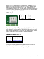
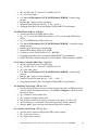
header#3 is for A/D Sensor#3, header#4 is for A/D Sensor#4, and header#5 is for A/D
Sensor#5. The headers run vertically so that a GP2D120 or GP2D12 IR Sensor can be
plugged in. Each header provides an input signal, +5 volts, and ground pin for the
connected IR Sensor. Be sure to plug your sensors into the correct pins, since an incorrect
connection can damage either the sensor and/or the board. Each input signal pin connects
to a corresponding A/D channel on the PIC18F4520.
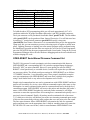
I2C Header, J7
Header Pin#
J7 Pin#1
J7 Pin#2
J7 Pin#3
Description
I2C SDA
I2C SDL
Ground
Figure#4, I2C Header, J7
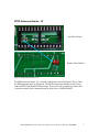
J7 provides access to the board’s I2C pins and ground, so that I2C devices can be
connected here. Pin#1 on J7 connects to SDA on the PIC18F4520, pin#2 connects to SCL
on the PIC18F4520, and pin#3 connects to ground on the PIC18F4520. You will need to
solder a suitable 3-position header to use the I2C and make the appropriate PIC18F4520
firmware changes since I2C is not supported in the supplied serial firmware.
GM-8 Motor Headers, J9 & J10
Header Pin#
J9 Pin#1
J9 Pin#2
J10 Pin#1
J10 Pin#2
Description
Left Motor Top Lead
Left Motor Bottom Lead
Right Motor Bottom Lead
Right Motor Top Lead
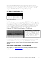
Figure#5a, GM-8 Headers, J9 & J10
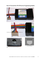
The left GM-8 gear motor connects to the J9 header and the right GM-8 to the J10
header. Connecting the GM-8’s incorrectly will only result in improper wheel rotation
and encoder readings and can be corrected by simply switching the motor leads.
OPEN-ROBOT Controller Board User Manual by Abe Howell’s Robotics, 8/22/2008
4