1
Please refer to the WW-02 Wheel Encoder User Manual for additional connection
information. You will need to either solder the WW02 cables directly to the appropriate
locations on J4 or purchase a suitable header, crimp pins, and connector to house the
crimp pins. WW02 Wheel Encoders must be purchased separately.
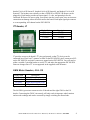
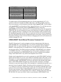
PIC18F4520 Serial Headers, J12
Header Pin#
J12 Pin#1
J12 Pin#2
J12 Pin#3
J12 Pin#4
Description
Connects to J11, pin2
Connects to J11, pin3
PIC18F4520 Serial RX
PIC18F4520 Serial TX
Figure#7, Serial Headers, J12
The J12 headers provide a connection point to the PIC18F4520’s Serial Port. Optionally,
you can use a set of jumpers to connect the TX and RX pins to the J11 header. To use this
feature simply attach a jumper across J12 pin#3 & pin#1 and a jumper across J12 pin#4
& pin#2. This is not necessary when using OPEN-ROBOT in its default configuration.
However, it might be useful if you decide to interface your own wireless hardware.
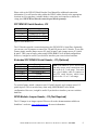
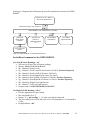
Extended PIC18F4520 Serial Header, J11 (Optional)
Header Pin#
J11 Pin#1
J11 Pin#2
J11 Pin#3
J11 Pin#4
J11 Pin#5
J11 Pin#6
Description
Pin Not Used
PIC18F4520 TX
PIC18F4520 RX
Ground
+5 volts
Pin Not Used
Note: This Board is a TTL device and
can only accept serial connections that
are in the 0 to 5 volt range. You must
use a level shifter cable to connect to
non-TTL serial devices, which have
levels in the –15 to 15 volt range.
Figure#8, Serial Header, J11
To use this feature, attach a jumper across J12 pin#3 & pin#1 and a jumper across J12
pin#4 & pin#2. This is not necessary when using OPEN-ROBOT in its default
configuration. However, it might be useful if you decide to interface your own wireless
hardware.
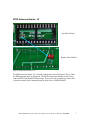
RFID Module Jumper Header, J13 (Not Required)
The J13 Jumper is no longer required. Please refer to the documentation available on
SonMicro’s web site: www.sonmicrom.com for more information.
OPEN-ROBOT Controller Board User Manual by Abe Howell’s Robotics, 8/22/2008
6