1
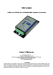
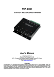
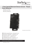
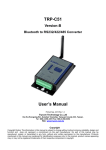
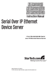
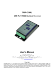
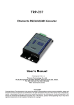
TRP-C36 Ethernet to 1 port RS232/422/485 Isolated Converter User’s Manual Printed Oct. 2013 Rev 1. Trycom Technology Co.,Ltd No.35, Zhongxing Rd., Guishan Township, Taoyuan County 333, Taiwan. Tel : 886-3-350-3351 Fax: 886-3-350-3352 Web: www.trycom.com.tw Copyright Copyright Notice: The information in this manual is subject to change without notice to improve reliability, design and function and does not represent a commitment on the part manufacturer. No part of this manual may be reproduced, copied, or transmitted in any form, without prior written permission by the manufacturer. Products mentioned in this manual are mentioned for identification purposes only. In this manual, product names appearing may or may not be registered trademarks of their respective companies or copyright. 1.Introduction TRP-C36, a high speed, single-port serial device, is designed to instantly convert data from RS232/422/485 interfaces to an Ethernet network running at the TCP/IP, UDP protocol. By using a standard COM port and existing network infrastructure the device allow you to link together RS232/22/485 serial devices that are distant from one another from Windows and Linux without the need to install any specific cabling or modify existing software. TRP-C36 supports 10/100Mbps auto-detecting, and auto RS485 data direction flow control, it also provides with 3000V DC isolation and internal surge protection to protect the converter from destructive voltage spikes and the danger of irregular power voltages input. The industry DIN rail and panel mounting design enable user a fast and professional installation. 1-1.Features Wide range power input voltage. Fully compatible with Ethernet TCP/IP, UDP protocol. Support 3000V DC isolation protection. Auto signal configure RS232, RS-422, and RS-485. Auto fast hardware direction flow control on RS-485. All RS422/485 signals provide surge and over current protection. Support baud rate up to 115.2 Kbps. Power/Link/TX /RX mode LED indicator. Support intranet and internet system setting function. Support screw terminal and standard external DC power adaptor. Operating System: Windows/Linux/Unix/MAC. DIN rail and panel mount. 1-2.Specifications Power Input Voltage: DC +10V to +30V. Interface: Standard RJ45 LAN port. RS232: 5 full-duplex (TXD, RXD, CTS, RTS, GND). RS422: Differential 4 full-duplex wires (TX+, RX+, TX- and RX-). RS485: Differential 2 half-duplex wires (D+, D-). Data Format: Asynchronous data with any combination of bits, parity, stop. Connection type: Screw terminal for maximum AWG #12~30 wire. Signal LED: Power, Link, TX, RX. Power supply: Screw terminal, or standard external DC adapter. Power consumption: 1.6W. Isolation Voltage: 3000V DC. Operating environment: -20 to 65℃. Storage temperature: -20 to 65℃. Humidity: 10~90% non-condensing. Dimension: 151mm X 111mm X 26mm. Weight: 375g. 2. Hardware Description 2-1.TRP-C36 panel layout 2-2. Block Diagram 2-3. LED Indictor PWR-: Power LED LINK LED: Ethernet Connection RX LED: RS232/422/485 data receiving TX LED: RS232/422/485 data transmitting DC Jack: Input from +10V to +30V. (Pleas use the 5.5*2.1*12 mm DC JACK). 2-4. Factory Button If by chance, you forget the setup password, or the incorrect settings making TRP-C36 unable to open, the following procedures can be used to return the TRP-C36 to factory default setting: Step1. Turn off the power of TRP-C36 device. Step 2. Press the reset button and hold. Step 3. Turn on the power (DC Jack) of TRP-C36 device. 2-5. TRP-C36 Default setting IP address: 192.168.1.1 Subnet mask: 255.255.255.0 Gateway address: None Network link speed: Auto 10/100MB DHCP client: Enable Socket port of HTTP setup: 80 Socket port of serial I/O: TCP Server Destination IP address: 0.0.0.0, TCP Server TCP socket inactive timeout (minutes):0 Serial I/O settings: 9600, N, 8, 1 Interface of serial I/O: Auto (RS232/RS422/RS485) Packet mode of serial input: Enable Device ID: 1 Report device ID when connected: Disable Setup password: None. 3. Install TRP-C36 hardware 3-1. Power Connection Connect power source with TRP-C36, if power properly supplies the PWR LED will light up. The TRP-C36 has a two pins terminal block and power jack. Power can apply on either terminal block or the power jack. It accepts 10-30VDC/500mA DC power supply. When power is properly supplied the PWR LED will up. Warning: User can only choose either External DC-Jack or Screw terminal DC input Do not use external DC-Jack and screw terminal DC input simultaneously. 3-2. Serial connection RS232 wiring connection The RS232 supports 5 channels plus Signal Ground and is configured as DTE like a computer. Signals are single ended and referred to Ground. To use handshaking or flow control user must set Host PC’s RTS/CTS during configuration. Refer to the pin assignment for connection as below. RS485 Wiring connection The RS485 mode supports the Transmit and Receive channels using 2-wire half-duplex operation. Refer to the pin assignment for connection as below. RS422 wiring connection The RS422 mode supports 4 channels with full duplex operation for Receive, Transmit, The data lines are in differential pairs. Refer to the pin assignment for connection as below. Notice: Due to the Hardware control problem will caused TRP-C08 under RS422/485 can't work, please take TRP-C36's RS232 screw terminal connector (RTS & CTS SHORT). 4. Install TRP-C36 software 4-1.STOEC Utility “STOEC” is the tool to enable user to detect and setup the on-line TRP-C36 hardware. User may find the utility in the TRP-C36 support CD. Double click STOEC, installShield Wizard will guide you to complete installation. 4-2. Introduction of STOEC utility Run STOEC utility Detect Click [Detect] button to detect on line TRP-C36 status. If TRP-C36 was properly installed it will be detected and found. If TRP-C36 was improperly installed it will not be found or detected. Notice: To assure STOEC utility run detecting process it is highly recommended user close XP firewall protection software. Set IP Click [Set IP] button User can set IP address here. Suppose user set IP address to be 192.168.0.112, Press [OK] I The IP address change to 192.168.0.112 Warning : ***.***.***.0 and ***.***.***.255 are invalid IP address for TRP-C36. If we input these IP address TRP-C36 will be locked Set Mask Click [Set Mask] button User can set Subnet Mask , the process is same as Set IP IE Click [IE] button.. If the IP address same as TRP-C36 IP address, then Press [OK] into the login page. . . NOTICE: TRP-C36 hardware Gateway address must be same as the computer Gateway address or the Login frame will not be found. Ping Click [Ping] button Press [OK], if ping successfully following page will be shown. If ping fail following page will be shown EXIT Press [EXIT] button to stop setting 5. How to configure TRP-C36 Setup of TRP-C36 is as easy as surfing on WWW, no special software will be required. The setup process can be easily done by popular Browsers, such as IE, or Netscape. In the browser URL field, set the IP address of device directly, the login page will be shown: System time elapsed: The time elapsed since start of this device in [Day Hour: Minute: Second] format. This information can be useful in identifying the reliability of system. Firmware version: TRP-C36 firmware is identified by date code. This information will be required in looking for technical support. Password: This field is the administration password for authentication. Factory default is empty. However, it is not recommended leave it empty in field operation. TRP-C36 uses the same password protection mechanism commonly used in Windows NT or UNIX. If there are more than 3 consecutive failure in password check during login, the login function will be disabled, even if you supply correct password, login will not proceed. This prevents intruders find password by computer generated program. .User may reset TRP-C36 to factory default and login again. TRP-C36 Hardware reset see point number 6. 5-1. Start to Setup After successfully login, the setup page will be shown as followings: 5-1-1 IP Address The IP address of TRP-C36 device is 4 digits, separated by '.' (xxx.xxx.xxx.xxx). If DHCP client mode is enabled and there's DHCP server on the network, this field will be assigned by DHCP server automatically. 5-1-2 Subnet mask Subnet mask of the network which TRP-C36 device connected to, 255.255.255.0 is usually used for small network, 255.255.0.0 for larger network. 4 digits, separated by '.' If DHCP client mode is enabled and there's DHCP server on the network, this field will be assigned by DHCP server automatically. 5-1-3 Gateway address Gateway IP addresses. 'Gateway' is a device which connects local network to external network. If there's no gateway on the network, just leave it as 0.0.0.0. If DHCP client mode is enabled and there's DHCP server on the network, this field will be assigned by DHCP server automatically. 5-1-4 DHCP client When DHCP disabled, IP address, Subnet mask, Gateway address can be manually assigned by user When DHCP enabled, IP address, Subnet mask, Gateway address will be dynamically assigned by DHCP serve and cannot be changed by the user. In “enable” status if a DHCP server is not available on the network the TRP-C36 will time out after 10 seconds and reset to the default values, the new IP will replace the original assigned IP, this could be resulted in the original TRP-C36 system program fail. 5-1-5 Socket port of HTTP setup The socket port used in the setup of TRP-C36. Normally, HTTP protocol use TCP port 80 for communication. Change this field may move HTTP port to 81, and leave port 80 for user's own Web. If HTTP port is changed to 81, the URL used for setup of TRP-C36 should be changed to "http://x.x.x.x:81", where x.x.x.x is the device IP address. 5-1-6 Socket port of serial I/O Socket port of UART data Port: 16 bit number, from 1 to 65535 Socket type: TCP Server TCP protocol, passive open to be connected from TCP client. TCP Client TCP protocol, active open to connect to TCP server. UDP UDP protocol, connectionless 5-1-8 Destination IP addresses / Socket port The server IP address and socket port to be connected in TCP Client and UDP mode. *5-1-9 TCP socket inactive timeout (minutes): This entry is designed to fix the problem when the socket is not properly closed by Windows. Though having not a formal bug report from Microsoft, more and more customers experienced the problem that sometimes they can not establish the socket between Windows and the device, because a previously closed socket in Windows is still connecting to the device. Since the device has only one socket for each physical serial port, once the socket is occupied by a previously opened socket, it will not accept any further connections. To make it back to normal state, you can only either reboot the device or reboot the host. The problem seems more likely to happen if the application is written in modern complicated software models, e.g. Visual Basic TCP/IP ActiveX, Visual Studio.Net, and the event-driven TCP/IP socket functions. For some reasons, probably bugs, Windows does not close the socket after the application software has already closed the socket, and still keeps the socket in CLOSE_WAIT or TIME_WAIT states. To solve the problem, we add a mechanism - "inactive timeout" to identify whether the socket is active or dead. If there is no any data transferred (send / receive) within the defined timeout period (1 to 99 minutes), then it is probably a dead socket, and the socket will be closed automatically, thus a new connection can be accepted again. The timeout period can be set by users to fit different kinds of application. It should be able to fix the Windows socket problem mentioned above. 5-1-10 Serial I/O settings (baud rate, parity, data bits, stop bits) Baud Rate 1200 ~ 115200 bps Parity None, Even, Odd Data bits 7 or 8 Stop Bit 1 or 2 Due to the limitation of 8051 series UART hardware, the total length of asynchronous frame (start + data + parity + stop ) can only be either 10 or 11 bits, so the possible combinations are: 10 bits: N,7,2 E,7,1 O,7,1 N,8,1 11 bits: E,7,2 O,7,2 E,8,1 O,8,1 N,8,2 5-1-11 Interface of serial I/O Auto(RS232/422/485) TxD, RxD for data stream, no flow control RS232 (RTS/CTS) RTS/CTS for flow control *TRP-C36 can auto detect interface of serial I/O, Select “Auto (RS232/422/485)’ user may neglect others selections, unless user only use the RS232 with flow control. 5-1-12 Packet mode of serial input Disable: Disable packet mode. Enable: Packet mode enable. If packet mode is enabled, the data input from UART will be deferred until input buffer full, or, detection of packet gap in which no more characters arrived. Packet mode inter-packet timeout Packet gap detection time constants, ranging from 10 to 3000 ms 5-1-13 Device ID User assigned ID number. 0 – 65535 5-1-14 Report device ID when connected In TCP mode, if report device ID enabled, when socket connected, TRP-C36 will immediately report device ID in following formats. Serial I/O socket nnnnnA[LF][CR] Digital I/O socket nnnnnB[LF][CR] The total length is 8 bytes. Where nnnnn is 5 digit device ID assigned by user, [LF] is decimal 10, [CR] is decimal 13 5-1-15 Setup password Administration password used in Login. The password can be empty or up to 15 character long. 5-2 Setup completely Press [Update] Button, TRP-C36 will save all parameters into internal non-volatile memory and then reboot. It takes about 5 seconds to complete the whole process, and a new login page will be presented. Press [Login] for double checking, or close the window to complete setup. 6. Firmware Upgrade As TRP-C36 firmware always keeps on enhancing with latest technologies and network standards, if your applications need the latest release of firmware, you will receive a Win32 executable software to upgrade the firmware in TRP-C36 through network: Connect TRP-C36 device to LAN. Firmware upgrade of TRP-C36 will not work on Internet. Set the target TRP-C36 device to have IP address in the same subnet as your host computer. In the DOS Prompt environment of Windows, execute the upgrade software you received with target TRP-C36 device IP address as the optional parameter. If you omit the target IP address, the upgrade software will try to find one automatically. The upgrade will start immediately with percent finished display on screen. Wait until 100% complete. Please note during upgrade, do not stop the software or remove the power of TRP-C36 devices, it will cause permanent damage of firmware and can not be recovered. 7. TRP-C36 operating mode The TRP-C36 can be configured as a TCP Client/Server or UDP. It can operate in “Paired Mode“, “Virtual COM” Mode”, and “Direct IP Mode”. 7.1 Paired Mode Paired mode is also called serial tunneling. When this type of configuration is selected, No additional software is needed to install in a host PC. In fact a PC is not required to make the connection. Any two dumb serial devices that can communicate with each other through a serial link will be able to communicate using two TRP-C36 and the LAN. Two TRP-C36 are configured with one setup as a TCP or UDP client and the other to TCP/UDP server. When setting up the Server, the Remote IP address section must contain the address of the Client. This will allow the Client’s IP address to pass the IP address-filtering feature of the Server. Conversely, the Remote IP address of the Client must contain the Server’s IP address. How to Setup TRP-C36 paired mode 1. Configure TRP-C36 server. IP address : 192.168.0.106 (for example) Socket port of serial I/O: Port 1001 ,TCP Server Socket port of digital I/O: port 101 , TCP Server 2. Configure TRP-C36 Client. IP address: 192.168.0.109 (for example) “TRP-C36 Client IP address must be different from TRP-C36 Server IP address” Socket port of serial I/O : 1001, TCP Client. Socket port of digital I/O: 101, TCP Client Destination IP address/Socket port (TCP client and UDP): 192.168.0.106, port 1001. The Client Destination IP address must be same as Server IP address (192.168.0.106), the Socket port number must be same as Server Socket port number” (1001) 7.2 Virtual Com Mode The Virtual COM mode requires the installation of a virtual COM port device driver. In this mode, the TRP-C36 must be set to either TCP/server or UDP/server in the menu with a designated communication port number. The virtual COM driver is a TCP or UDP client. Once the connection is made, the LAN is transparent to the serial device. Applications work just as if the serial device is connected a host’s physical COM port. The virtual COM port converts the application’s data into IP packet destined for the TRP-C36, which in turn converts the IP packet back to serial data. Point # 9 will guide you setup Virtual COM mode. 7.3 Direct IP Mode mode Direct IP connections allow applications using TCP/IP or UDP/IP network socket programs to communicate with the asynchronous serial port on the TRP-C36. In this type of application the TRP-C36 is configured to TCP or UDP server. The socket program running on the PC establishes a communication connection with the TRP-C36. The raw data is sent directly to and from the serial port. “TRPCOM Test Utility” is demo utility which may help to test direct IP Mode .User may find the utility in the TRP-C36 disk. Double click “Trycom Utility”, the installShield Wizard will guide you complete installation. 8. About virtual COM User can find the virtual COM software in TRP-C36 support CD. VSerPortConsole_2000 for Windows 2000 VSerPortConsole_XP for Windows XP TRP-C36 Virtual COM software do not support Windows 98/Me How to set Virtual COM port Run the “VserPortConsolem2000” utility. ** If user’s operating system is Win XP or XP sp2 , it is strongly recommended to disable XP firewall before running VserPortConsole,** Fig.1 If no Virtual RS232 port exist ,the dialogue window is empty。 Move your mice cursor to the place under VirtualSerialPort Console click the mice right button, you will see Fig.2 。 Fig.2 .Select “ Add Port”,wait for a while , you will see Fig.3.。 Fig.3 Click OK you will see Fig.4 Fig.4 Click OK go to Fig.5 , you will find there is a Virtual RS232 port 。 Fig.5 Move your mice cursor to the RS232 port that you want to use (for example COM 11), and click the mice right button, you will see Fig.6. t Fig.6 Select Add Net , you will see Fig.7. You can start the 232 port’s TCP server、TCP xlient or UDP setting。 Fig.7 Example: We select COM6 and COM10 for data communication by UDP protocol. COM6. Go to Fig.6, select COM6. for Add Net setting Select UDP. (Fig.8) Set Local port=30000,IP=127.0.0.1,Remote port=31000。 COM10 Go to Fig.6, Select COM10 for Add Net setting. Select UDP. (Fig.8) Set Local port=31000,IP=127.0.0.1,Remote port=30000。 Fig.8 After COM6 and COM10 setting , you will see the Fig.9。 Fig.9 9. How to test TRP-C36 Trycom Technology Co.,Ltd offers test utility, this is utilities may help user to demo and test TRP-C08 fast and easily. User may find the utilities in Trycom support CD or download from Trycom web www.trycom.com.tw , direct to perform TRPCOM.exe from the directory. 9-1.RS232 Loop Back Test RS232 loop back test wiring connection. 9-2.RS422 Loop Back Test RS422 loop back test wiring connection. 9-3.Loop Back Test Software STEP1: Run the “TRPCOM.EXE” utility. STEP2: Click the “Setting” to set the com port and baud rate then press OK . *Please note: “COM2” is an example of COM port number; the real COM number is assigned by user PC. STEP3:. Click the "Terminal" then select Loop back enable, the counter value and pass value will be synchronized counts. 9-4. RS485 test RS485 test mode, it can be connected to RS485 Device, such as connecting TRP-C28, send "$01M" instruction from the client side, when the TRP-C28 received command that will response "!01TRPC28" indicates execution completed. Step1. Run TRPCOM.exe utility. Step2. Click the “Setting” to set the com port and baud rate then press OK. Step3.Send command “$01M” and press “Send” button. Step4. TRP-C28 response received. 10. Application