1
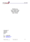
TAC 200 OTP
Compensator and optimiser
Handbook
0-004-1400-0 (SE), 2000-02-08
TAC 200 OTP Handbook
Contents
TAC 200 OTP
Handbook
This document contains proprietary information of TAC AB and is made available solely to those who operate and maintain Tour & Andersson
equipment. Disclosure, reproduction or use of either the documents or the information contained herein for any other purpose is strictly
prohibited.
TAC AB reserves the right to make changes or additions to material as necessary.
© 1994 TAC AB
Contents
1
Introduction
1.1 TAC 200 OTP compensator and optimiser ............................................................................. 1:1
1.2 This manual .............................................................................................................................. 1:1
1.3 More information ..................................................................................................................... 1:2
2
General
2.1
2.2
2.3
2.4
3
Mounting .................................................................................................................................. 2:1
Connections .............................................................................................................................. 2:3
Operator’s panel ...................................................................................................................... 2:4
Commissioning ......................................................................................................................... 2:6
Daily operations, P:00–P:15
3.1 List of available functions ........................................................................................................ 3:1
3.2 Description ............................................................................................................................... 3:2
4
Special functions, P:16–
4.1 List of available functions ........................................................................................................ 4:1
4.2 Restart ...................................................................................................................................... 4:3
4.2.1
4.2.2
4.2.3
Returning to factory settings ......................................................................................................................... 4:3
Not returning to factory settings ................................................................................................................... 4:3
Power failure ................................................................................................................................................. 4:3
4.3 Control functions ...................................................................................................................... 4:4
4.4 Reset curve ................................................................................................................................ 4:5
4.4.1
Supply water temperature controller ............................................................................................................ 4:7
4.5 Room temperature control ....................................................................................................... 4:8
4.5.1
4.5.2
System with a room sensor ........................................................................................................................... 4:8
System without a room sensor ...................................................................................................................... 4:8
4.6 Night setback and Morning boost ............................................................................................ 4:9
4.6.1
4.6.2
Night setback ................................................................................................................................................. 4:9
Morning boost ............................................................................................................................................... 4:9
4.7 Extended day/night operation ............................................................................................... 4:10
4.8 Start time optimisation ........................................................................................................... 4:11
TAC AB, Feb 2000
TAC 200 OTP Handbook
Contents
4.9 Pump control .......................................................................................................................... 4:13
4.9.1
4.9.2
Pump cut off ................................................................................................................................................ 4:13
Pump exercise .............................................................................................................................................. 4:13
4.10Frost protection ...................................................................................................................... 4:14
4.11Time functions ........................................................................................................................ 4:15
4.11.1 Daylight saving time ................................................................................................................................... 4:15
4.12Test functions ......................................................................................................................... 4:16
4.12.1 Program version .......................................................................................................................................... 4:16
4.12.1 Relay outputs ............................................................................................................................................... 4:16
5
Technical data
5.1 Technical data .......................................................................................................................... 5:1
5.2 Factory settings ......................................................................................................................... 5:2
5.3 Part numbers ............................................................................................................................ 5:3
TAC 200 OTP Commissioning protocol
This manual contains in all 21 leaves.
TAC AB, Feb 2000
TAC 200 OTP Handbook
Introduction
1 Introduction
1.1 TAC 200 OTP compensator and optimiser
TAC 200 OTP is a compensator and an optimiser. It controls the heating via a
boiler output and a mixing valve or via two stages of gas boilers.
TAC 200 OTP can be operated with or without a room sensor.
The controller has an easy-to-use operator’s panel and needs virtually no
maintenance.
1.2 This manual
This manual has the following content.
Chapter 2
This chapter shows how TAC 200 OTP is mounted, connected and commissioned. There is also a description of the operator’s panel with its symbols. To
show the use of the operating buttons, there is a detailed description of how to
set the date and time.
When the time has been set, TAC 200 OTP immediately starts controlling,
using the factory settings.
Chapter 3
This chapter describes the daily operations of TAC 200 OTP. You can read
temperature values, enter setpoints and change the time program for day and
night time operation.
Chapter 4
When a plant is commissioned and fine-tuned, it may be necessary to adjust
some of the parameters. The controller function and available parameters are
described in chapter 4.
Chapter 5
This is a summary of the technical data of TAC 200 OTP. There is also a list
of all the factory settings used at a restart.
At the end of the manual there is a commissioning protocol, where entered
values should be noted.
TAC AB, Feb 2000
1:1
TAC 200 OTP Handbook
Introduction
1.3 More information
TAC 200 OTP is also described in the following documents, all available in
English :
•
Data sheet TAC 200 OTP C-10-31
The data sheet contains a comprehensive specification of the controller and
should be read together with the handbook (part number 0-003-1148).
•
A brief instruction
A small leaflet normally placed in a slot in the operator’s panel (part number
0FL-3564).
•
User’s manual TAC 200 OTP
The user’s manual (part number 0FL-3563) is a description for installation
and start-up, packed together with the unit. The contents are a condensed
version of chapter 2 in this manual and a mounting instruction.
1:2
TAC AB, Feb 2000
TAC 200 OTP Handbook
General
2 General
2.1 Mounting
TAC 200 OTP controller
TAC 200 OTP is encased in a plastic enclosure with a transparent cover.
The controller can be mounted in three ways, either directly on the wall,
on a DIN rail or in a panel. There are cable inlet holes on three sides.
The controller is attached to the base and should be removed as shown
below. Mount the base plate in an easily accessible position where the
display is clearly legible. Connect the wires according to the wiring
diagram. Screw the controller back onto the base plate. There are holes in
the base plate for mounting the controller directly onto the wall if
preferred.
Separation of the controller from the base plate
To mount the controller on a DIN rail, place the controller on the upper
edge of the rail and press it inwards to snap it into place, see next page.
To remove it again, place a screw driver in the red piece of plastic on the
lower part of the controller, pull downwards and then pull the controller
upwards from the rail.
TAC AB, Feb 2000
2:1
TAC 200 OTP Handbook
General
Mounting of the controller on a DIN rail
To mount the controller in a panel the space needs to be 138×92 mm.
Place the controller in the panel and turn the small plastic hooks in the
controller’s screw holes to secure it.
Outdoor sensor EGU
Mount the sensor on an external wall, facing north or north-west. The
sensor should be placed about 3 m above ground level and the cable inlet
should face downwards.
Supply sensor EGWS/EGA
The immersion sensor EGWS is mounted in the riser pipe, some 0,5–1 m
downstream of the mixing valve. If an EGA strap-on sensor is used, it
should be mounted on an uninsulated part of the pipe. Clean the pipe
thoroughly so that the copper contact plate of the sensor makes good
contact with the pipe.
Room sensor EGRL
To achieve the best performance, the following should be taken into
consideration when mounting the room sensor:
•
The sensor should be installed in a room which is typical of the
building.
•
The sensor should be placed on an inner wall of light building
material.
The wall must not be heated by, for example, uninsulated heating
pipes
behind it.
•
The room should be of sufficient size for the temperature not to be
adversely affected by people or machinery.
•
The radiators of the room should not have thermostat valves. If
they
have they should be turned to the largest value possible.
•
The room sensor should be placed so that the air can flow freely
around
it.
2:2
TAC AB ,Feb 2000
TAC 200 OTP Handbook
General
•
The room sensor should be placed within 10 m from the nearest
radiator, but not right above it.
Actuator (M44, M5, M15, M42)
Mounting instructions are supplied with the actuator/mounting kit.
230 V/L
1 L
M 10
230 V/N
2 N
B1 11
Supply temp. sensor
3 PE
B2 12
Outdoor sensor
4 KC1
B3 13
Room sensor
5 K1
M 14
6 K2
X1 15
7 KC2
X2 16
Pump
8 K3
X3 17
Boiler
9 K4
M 18
R
M15/
M44 B
Forced day op.
(230 V)
W
230 V/L
1 L
230 V/N
2 N
Forced night op.
3 PE
4 KC1
Stage 1
Stage 2
5 K1
6 K2
7 KC2
Pump
8 K3
Boiler
9 K4
2.2 Connections
Wiring
Connect the cables to the controller according to the wiring diagram, see
below.
Wiring diagram
TAC AB, Feb 2000
1
2
3
4
5
6
7
8
9
230 V/L Mains, phase (live)
230 V/N Mains, neutral
PE
Protective earth
KC1
Voltage supply, relays K1 and K2
K1
Relay K1: increase/stage 1
K2
Relay K2: decrease/stage 2
KC2
Voltage supply, relays K3 and K4
K3
Relay K3: pump
K4
Relay K4: boiler
10
M
Measurement neutral
2:3
TAC 200 OTP Handbook
General
11
12
13
14
15
16
17
18
B1
B2
B3
M
X1
X2
X3
M
Supply sensor, EGWS/EGA
Outdoor sensor, EGU
Room sensor EGRL
Measurement neutral
Input, forced day operation
Input, forced night operation
Not in use
Measurement neutral
TA 200 OTP has six cable inlet holes:
-
2 in the base plate for conduit fitting Pr 18,6 (Pg 11),
and
2 for cables with rubber bushings on the upper side of the case,
-
2 for cables with rubber bushings on the lower side of the case.
Cables for power supply and for temperature sensors should be installed
well separated (spaced 20 cm or more).
Signal and power supply cables, that enter the casing from the rear, must
be routed well separated.
Also 24 V power supply cables must be installed in compliance with
Brief instruction
Display
/
P
–
+
P
Buttons
local high voltage wiring regulations in force.
Length of cables
To terminals B1–B3 and X1–X3:
To other terminals:
Max. 200 m, area 0,5 mm2.
Max. 100 m, area 1,5 mm2.
2.3 Operator’s panel
The operator’s panel
The operator’s panel consists of a semi-graphic display, a brief
instruction with the functions and the following buttons:
2:4
TAC AB ,Feb 2000
TAC 200 OTP Handbook
General
P
+
P
Use these buttons to move up and down the list.
–
Use these buttons to increase or decrease the value shown on
the
display. Keep either of them depressed to increase the stepping
7
8
9
10
11
12
13
14 15
16
17
18
6
MO
5
TU
WE
TH
FR
SA
SU
19
4
P:00
3
12:34
2
1
AM
°C
Ι ΙΙ
K4
0
20
21
22
23
24
speed.
/
Use this button to change between day and night in the seg-
ments of
30 minutes.
To save alterations, press P or P again. Failure to carry out this step
will result in the changes not being saved and the controller reverting to
the old value in approximately two minutes.
P:nn in the display indicates the current function used, see below. P:00,
for example, means time of day and operating mode.
If no key has been touched for about two minutes, the display will always
revert to P:00, time/operating mode.
The display
Depending on the configuration of the system (section 2.4), i.e. what
kind of units are connected, some of the functions may be omitted on the
display.
The TA 200 OTP display has a number of letters and symbols which are
used to indicate status or assist in the input.
On the operator’s panel there are a number of special characters which
denote specific functions and also operating mode.
K4
II
II
0–24
P:xx
TAC AB, Feb 2000
Circulating pump running
Boiler running
Forced off
Forced night operation
Automatic control
Forced day operation
On/off control: stage 1 on
On/off control: stage 2 on
Mixing valve: decrease
Mixing valve: increase
Selected time interval, in half-hours
Selected function xx, i.e. display or change value
2:5
TAC 200 OTP Handbook
General
12:34
ing to
Current time of the day (at P:00), or some other value, accord-
selected function P:xx
AM/PM 12-hour clock display
°C
Current temperature scale
Current weekday according to:
MO
TU
WE
TH
FR
SA
SU
Monday
Tuesday
Wednesday
Thursday
Friday
Saturday
Sunday
2.4 Commissioning
After the controller has been mounted and the electrical wiring is completed, the following checks should be carried out and the settings
entered before operation of the installation.
1.
Check that sensors and actuators are correctly wired.
1 2
3
4
5
6
7
8
on (1)
off (0)
2.
Set the DIP switches on the circuit board, located under the brief
instruction, as required.
Switch
Position off (0)
Position on (1)
1
on/off control
mixing valve
2
radiator system
floor heating
3
no room sensor installed room sensor
4–7
(no function)
8
(hardware reset when switched 0–1–0)
Switches 4–8 should be in the off position.
DIP switches
3.
Switch on power.
4.
Set current time and date, see 3.2.
5.
Put the brief instruction back in its place.
TAC 200 OTP will now control, using the factory settings. To set values
other than those set at the factory, see chapters 3 and 4.
2:6
TAC AB ,Feb 2000
TAC 200 OTP Handbook
Daily operations, P:00–P:15
3 Daily operations, P:00–P:15
3.1 List of available functions
The following functions are reached with
values are displayed.
P:
Meaning
P:00
P:01
P:02
P:03
P:04
Time/Operating mode
Room temperature
Outdoor temperature
Supply water temperature
Supply water temperature setpoint
P:05
P:06
P:07
P:08
P:09
Room temperature setpoint
Night setback (°C)
Parallel shift reset curve (°C)
Time program, day-by-day
Time program, 1–7 days
P
and
P
and the corresponding
P:13 Set time
P:14 Day.Month
P:15 Year
These functions are listed on the brief instruction. The operating procedures
are described in section 2.3 and the factory settings in 5.2. On the following
pages, there are explanations of the functions mentioned above.
TAC AB, Feb 2000
3:1
TAC 200 OTP Handbook
Daily operations, P:00–P:15
3.2 Description
P:00 Time/Operating mode
P:00 is the normal display mode and shows the current time.
The temperature of the building can be lowered for a longer period of time, e.g.
if it is empty during a holiday, or if the day temperature is required for a couple
of hours extra one night, without changing the TA 200 OTP program. The
controller can also provide day or night temperature all the time or be turned
off without losing the settings.
It is possible to toggle between the following operating modes on the operator’s
panel:
Forced off
Forced night operation
Automatic operation (control by the time program)
Forced day operation
During forced off, the controller is turned off without losing the settings.
However, the frost protection will be active.
During forced night operation the controller provides night temperature all the
time. In the same way, the controller provides day temperature all the time
during forced day operation.
During automatic operation, the controller provides day and night temperature
according to the programmed settings.
To change the operating mode:
1.
Press P or P until P:00 (Operating mode) is displayed (if it is not
already shown).
2.
Press
+
or
–
until the desired symbol is activated.
If forced day or night operation has been activated from outside the controller
(Extended day/night operation, see section 4.7), the corresponding symbol
flashes.
Externally forced operation (X1, X2) has a higher priority than any locally
forced operation.
The three stages of frost protection are active during night operation and
during forced off mode. If the outdoor temperature falls below a preset value,
the first stage will start the circulating pump. The second stage will start the
boiler if the supply water temperature falls below a preset value. When a room
sensor is fitted, the third stage will start the plant to maintain a preset minimum
room temperature.
P:01 Room temperature
P:02 Outdoor temperature
P:03 Supply water temperature
Temperature readings are shown in °C. The display is continuously updated,
but after about 2 minutes, if no button has been pressed, the display will revert
to P:00 to show the time.
3:2
TAC AB, Feb 2000
TAC 200 OTP Handbook
Daily operations, P:00–P:15
P:04 Supply water temperature setpoint
The setpoint for the supply water is calculated by the controller. The current
value, in °C, is shown here.
The value cannot be changed from the display.
Temperature setpoint
Setting temperature setpoint:
1.
Press
P
or
P
to display P:05, P:06 or P:07.
Function
displays
P:05
room temperature setpoint (°C) (with room sensor)
P:06
night setback (°C) (without room sensor)
P:07
parallel shift reset curve (°C) (without room sensor).
2.
Press + or – until the display shows desired value. Keeping the
button depressed increases the stepping speed.
3.
Store changes by pressing
P
or
P
at least once.
P:05 Room temperature setpoint (°C)
This is used when a room sensor is fitted. The room sensor will displace the
reset curve to achieve optimum control of the room temperature.
P:06 Night setback (°C)
If no room sensor is used, the reset curve is parallel displaced during night
operation. A negative value will lead to a decrease of the temperature.
If a room sensor is used, the boiler and the circulating pump are turned off
during night operation and only turned on to protect the system from freezing.
P:07 Parallel shift reset curve (°C)
The temperature curve can be adjusted upwards or downwards by the amount
of degrees given. This is used only when there is no room sensor.
P:08 Time program, day-by-day
P:09 Time program, 1–7 days
The digital clock has a time program, which is used for switching between day
and night temperature. All times can be set individually for every day of the
week, with a resolution of 30 minutes. The segments—each is 30 minutes
long—on the 0–24 scale show when day and night temperature are used,
starting with Monday (MO displayed). A black segment denotes day
temperature setpoint and a white one night. By picking suitable on/off times,
operation will always occur within 15 minutes of any desired time value.
TAC AB, Feb 2000
3:3
TAC 200 OTP Handbook
Daily operations, P:00–P:15
Setting the time program, day-by-day:
1.
Press
2.
Press + or – until you reach the segment you want to change. The
segment flashes.
3.
Press / . The colour of the segment changes and the flashing skips to
the next segment.
4.
If you press + , and you are at the last segment, the display changes to
the following day. If you are in the first segment and press – , the
display changes to the previous day.
5.
Mark all the segments of all day-and-night periods as desired.
6.
Use the same procedure to mark the segments for each day of the week.
7.
Store the changes by pressing
or
P
until P:08 (Time program 1, day-by-day) is displayed.
P
P
or
P
at least once.
Day the entry is valid for
7
8
9
11
10
12
13
14 15
16
17
18
6
MO
5
Move flashing
segment with
or
+
–
19
4
20
P:08
3
21
2
22
1
23
0
24
Flashing segment:
Change indication with / . A black
segment indicates day and a white night.
Pressing + when this segment is
flashing, will make the flashing
switch to the next day.
Setting the time program day-by-day
If the same pattern for day/night setpoint is required for several days, either
repeat the above or, for speed, use P:10 (Time program, 1–7 days). The days
of the week and the 0–24 segments can then be changed in the same procedure.
Setting the time program, 1–7 days:
3:4
1.
Press
2.
Press
+
3.
Press
/
4.
Remove all the days for which thechange should not apply in the same
way. Make sure that the days to which the changes apply, are visible on
the display.
5.
The flashing weekday indication will automatically skip to the
segments of 30 minutes when passing either Sunday or Monday (in
reverse direction).
P
or
or
P
–
until P:09(Time program, 1–7 days) is displayed.
until the first day to be removed flashes.
. The marked day disappears.
TAC AB, Feb 2000
TAC 200 OTP Handbook
Daily operations, P:00–P:15
6.
When day setpoint is required, mark the segments in the same way as
above.
7.
Press
8.
To set other times for other days, return to P:10 and repeat steps 2–7 for
these days.
or
P
P
to save the changes.
Note! Take care as this operation changes several days at the same time.
Move flashing
segment with
or
+
Flashing day:
Pressing + when this segment is
flashing, will make the flashing
switch to the segments of
30 minutes.
Change indication with / . Visible days
indicate which days the segments of
30 minutes are valid for.
–
7
8
9
11
10
12
13
14 15
16
17
18
6
MO
5
TU
WE
TH
FR
SA
SU
19
4
20
P:09
3
A black segment
indicates day and
a white night.
21
2
22
1
23
0
24
Setting the time program for 1–7 days
P:13 Set time
P:14 Day.Month
P:15 Year
Note! TA 200 OTP automatically switches to and from daylight saving time,
even in leap years. The dates for change over can be set manually if desired, see
section 4.11.1.
Setting time and date:
1.
Press
2.
Press either + or – until the controller shows current time, e.g.
09:45. Keeping the button depressed increases the stepping speed.
3.
Press
4.
Press
5.
Press
6.
Press
7.
Press P so that P:00 (Display time) is displayed. The time value is
now stored.
P
P
+
P
+
or
P
, until P:13 (Set time) is displayed.
, so that P:14 (Day.Month) is displayed.
or
–
until the controller shows current date e.g. 29.11.
so that P:15 (Year) is displayed.
or
–
until the controller shows current year, e.g. 1994.
If P or P is not pressed as the last step, any changes will not be stored
(applies to all entries). In this case the display will automatically revert to P:00
in about two minutes.
TAC AB, Feb 2000
3:5
TAC 200 OTP Handbook
Special functions, P:16–
4 Special functions, P:16–
4.1 List of available functions
The functions P:16–P:66 are normally only used during commissioning or if
special adjustments are required.Normally it is sufficient to use P:00–P:15 and
for this reason the display scrolls through P:15–P:00, or vice versa.
To access functions P:16 and higher:
1.
Simultaneously press
2.
Press
P
or
P
P
and
P
to get to P:16.
to step up or down within the new interval. To return
to P:00–P:15, either press P and P simultaneously, or wait for
approximately two minutes for the controller to return to P:00
automatically.
These are the functions P:16–P:66:
P:
Meaning
P:16 Max. supply water temperature
P:17 Min. supply water temperature
}
P:18
P:19
P:20
P:21
P:22
x(1)
y(0)
Reset curve
y(1)
dimension points
y(2)
Start time curve adjustment
P:23
P:24
P:25
P:26
P:27
Start time low
Start time high
Max. holiday compensation adjustment
Max. start time (h)
Optimisation tolerance (°C)
P:29
P:30
P:31
P:32
Room sensor authority
Room I time (minutes)
Room dead band (°C)
Min./Max. room influence (°C)
P:34
P:35
P:36
P:37
Supply P band (°C)
Supply I time (minutes)
Running time actuator (s)
°C×min at on/off
P:38 Morning boost time (minutes)
P:39 Morning boost (°C)
TAC AB, Feb 200
4:1
TAC 200 OTP Handbook
Special functions, P:16–
P:40
P:41
P:42
P:43
Pump cut off (1=on, 0=off)
Pump exercise (1=on, 0=off)
Outdoor temperature pump cut off
Supply water temperature pump cut off
P:44 Room temperature frost protection
P:45 Supply water temperature frost protection
P:46 Outdoor temperature frost protection
P:47 Time format 12/24 h
P:48 Daylight saving time (DST)
0:off, 1:auto, 2:man
P:49 DST Day.Month
P:50 DST time of day
P:51 Standard time, Day.Month
P:52 Standard time, time of day
P:53 DST offset
P:54
P:60
P:61
P:62
P:63
P:64
P:65
P:66
Restart: ’+’gives factory settings
Program version
Manual control K1 (increase/stage 1)
Manual control K2 (decrease/stage 2)
Manual control K3 (pump)
Manual control K4 (boiler)
Test all segments
Dead band supply water temperature
These functions are listed on the brief instruction. On the following pages,
there are explanations of the functions mentioned above.The factory settings
are listed in section 5.2.
4:2
TAC AB, Feb 2000
TAC 200 OTP Handbook
Special functions, P:16–
4.2 Restart
4.2.1
Returning to factory settings
P:54 Restart
P:54 is described first, because it may be used to reset all settings and to restart
the controller. This is an advantage if you are in doubt about the entered
settings of the controller.
All the manually entered settings will be lost after this restart command, as they
are replaced by the factory settings. The clock will also be set to zero. The
factory settings are listed in section 5.2.
To restart the controller and regain the factory settings:
1.
Press
P
and
2.
Press
P
or
3.
Press
+
P
P
to reach P:16.
until P:54 is shown on the display.
.
The display will show P:00, with the time flashing 00:00, indicating that time
and date has to be set (section 3.2). The controller will control with forced day
operation until the time is set. Then it will control according to the time
program.
4.2.2
Not returning to factory settings
If the controller has stopped working, it may need to be restarted. To do this
switch DIP switch 8, behind the brief instruction on the front of the controller,
to on and then back to off. All the settings remain in the controller.
4.2.3
Power failure
The controller maintains the settings for at least twelve hours during a power
failure. The clock keeps running and when the power returns, the controller
continues to control the system as if nothing had happened. Should the power
failure last longer than twelve hours, the time, date and year will require resetting.
TAC AB, Feb 200
4:3
TAC 200 OTP Handbook
Special functions, P:16–
4.3 Control functions
TA 200 OTP has two separate control functions:
–
one controller for the room temperature, and
–
one controller for the supply water temperature.
The controller for the room temperature is used only when there is a room
sensor. It is recommended to use a room sensor, as the room temperature
controller is very efficient in using the heat stored in the building. A room
sensor can be used both in mixing valve and on/off control.
The influence of the outdoor temperature on the supply water temperature is
determined by the reset curve. The reset curve is modified with an offset,
directly or via the room temperature controller, by the night setback or morning
boost.
If the room temperature controller is active, the offset will also be affected by
the requested setpoint, the current room temperature and the min./max. limits,
if specified.
The resulting value may in turn be reduced by min./max. limits, resulting in the
SPsupply value.
The pump can be made to turn off at high outdoor temperatures or if SPsupply
has a low value.
Each of these functions is described in more detail in the following.
Pump
Pump
on/off
Reset
curve
Outdoor
temperature
SPcurve
SPsupply
Time
program
Night setback
Morning boost
(Without room sensor)
+
SPoffset
Min./max.
limits
REG Supply
water temp.
Supply water
temperature
Heating
unit
MVsupply
Start time
optimisation
+
P:05
SProom
Room
temperature
MVroom
REG
Room
temp.
Min./max.
limits
(With room sensor)
Block diagram for the controllers of TAC 200 OTP
4:4
TAC AB, Feb 2000
TAC 200 OTP Handbook
Special functions, P:16–
4.4 Reset curve
TAC 200 OTP determines the setpoint of the supply water temperature from
the measured outdoor temperature. The relationship between the outdoor
temperature and the supply temperature is given by means of a reset curve
with three adjustable curve points, see the figure below.
Depending on whether radiator or floor heating system has been selected, two
different basic reset curves apply. By setting DIP switch 2, indicating a
radiator or floor heating system, you get the curve that is best suited for the
application.
Also the high limit of the setpoint for the supply temperature will be different
in the two cases.
tsupply y (°C)
120
100
max. 80
60
40
toutdoor
20
10
–20
x (°C)
–10
0
10
20
Reset curve (default) for a radiator heating system
tsupply y (°C)
60
50
40
30
20
toutdoor
10
x (°C)
–20
–10
0
10
20
Reset curve (default) for a floor heating system
The reset curve is based on three dimension points, defined at the outdoor
temperatures –10 °C, +20 °C and one adjustable temperature between –9 °C
and +19 °C.
The corresponding supply temperature of each dimension point is individually
adjustable from the display.
TAC AB, Feb 200
4:5
TAC 200 OTP Handbook
Special functions, P:16–
The room sensor permits parallel displacement of the reset curve.
If the system is not equipped with a room sensor and there is a constant
deviation from the desired room temperature, the reset curve may be adjusted
upwards or downwards by the function P:07, see section 4.6.1.
tsupply y (°C)
P:21
120
y(2)
100
80
P:20
60
P:18
y(1)
P:19
40
y(0)
toutdoor
20
10
–20
x (°C)
–10
10
0
20
x(1)
Reset curve adjustment
P:18 x(1)
P:19 y(0)
P:20 y(1)
P:21 y(2)
The reset curve is adjusted with P:18–21.
Note that only one x-coordinate, x(1), may be changed, the other two are fixed.
The y-coordinates are all adjustable.
P:16 Max. supply water temperature
The maximum limit for the supply water temperature is set here.
P:17 Min. supply water temperature
The minimum limit for the supply water temperature is set here.
4:6
TAC AB, Feb 2000
TAC 200 OTP Handbook
4.4.1
Special functions, P:16–
Supply water temperature controller
The supply water temperature controller uses these parameters.
P:34 Supply P band (°C)
The deviation in supply water temperature needed to make the actuator go
from fully open to fully closed, or vice versa, is set here.
P:35 Supply I time (minutes)
The time required of the system to eliminate a deviation in supply water
temperature, is set here. If this time is set too short, the supply water
temperature may start oscillating.
P:36 Running time actuator (s)
The time the actuator needs to go from fully open to fully closed, or vice versa,
is set here.
P:37 °C×min at on/off
When on/off control is used, the delay time in degree-minutes until the next
stage is switched on (or off) is given by this function.
Example
If P:37=15 and the control error is 1 °C, it will take 15 minutes before the next
stage is changed (1 °C×15=15). If the error is 3 °C, it will take only 5 minutes
(3 °C×5=15).
P:66 Dead band supply water temperature
The deviation from the supply water temperature setpoint, which the controller
accepts before it increases or decreases the supply water temperature, is set
here. The limits are the supply water temperature setpoint ± the set value.
Example
If the setpoint is 70 °C and P:66=2 °C, the limits are 72 °C and 68 °C.
TAC AB, Feb 200
4:7
TAC 200 OTP Handbook
Special functions, P:16–
4.5 Room temperature control
The room temperature is controlled via the supply water temperature, i.e. the
room temperature controller calculates an offset from the outdoor
compensated reset curve and thus adjusts the supply water setpoint. The
controller has proportional (P) and integral (I) action with adjustable
parameters.
The supply water temperature setpoint, P:04, is calculated as the sum of values
from the outdoor compensated reset curve (with a possible parallel displacement), the morning boost (section 4.6) and the room temperature control offset.
4.5.1
System with a room sensor
When a room sensor is used, it will automatically displace the reset curve for
achievement of optimum room temperature control. If there is a room sensor,
the controller controls the room temperature with the following parameters, by
parallel displacement of the reset curve.
P:29 Room sensor authority
The alteration of the supply water temperature from the room control loop at
1 °C room temperature deviation, is set here.
Example
If the room temperature is 2 °C too low and the room sensor authority is set
to 3, the supply water temperature is increased by 6 °C (3×2 °C).
P:30 Room I time (minutes)
The time required of the system to eliminate a deviation in room temperature is
set here. If this time is set too short, the room temperature may start oscillating.
P:31 Room dead band (°C)
The deviation from the room temperature, that the controller accepts before it
changes the supply water temperature, is set here.
P:32 Min./Max. room influence (°C)
The influence from the room sensor on the supply water temperature may be
limited. The limits are set as an offset.
Example
If P:32=15 °C, the room sensor can shift the supply water temperature ±15 °C.
4.5.2
System without room sensor
If there is no room sensor, there is no adjustment of the reset curve. However,
the supply water temperature setpoints can be parallel displaced by setting the
parallel shift reset curve, P:07, to a value not equal to zero.
4:8
TAC AB, Feb 2000
TAC 200 OTP Handbook
Special functions, P:16–
4.6 Night setback and Morning boost
If desired, TAC 200 OTP can lower the supply water temperature during the
night, so called night setback. If no room sensor is used, the reset curve is
parallel displaced during night operation. If a room sensor is used, there is no
night setback. Instead the boiler and the circulating pump are turned off
during night operation and only turned on to protect the system from freezing.
4.6.1
Night setback
P:06 Night setback (°C)
This function, and P:07, is used if there is no room sensor. The reset curve
will be displaced by the amount of degrees given during night operation.
A negative value will lead to a decrease of the temperature.
P:07 Parallel shift reset curve (°C)
If no room sensor is used, the reset curve can be parallel displaced. The
temperature curve is adjusted upwards or downwards by the amount of
degrees given.
A positive value makes the temperature rise.
4.6.2
Morning boost
TAC 200 OTP is equipped with morning boost to ensure that the heating
system can restore the room temperature after a night setback. During morning boost the supply water temperature setpoint is increased by a preset value.
This value is adjustable. If no room sensor is used, the morning boost starts
when the controller turns from night to day operation. If a room sensor is used
the start time will be optimised, see section 4.8.
P:38 Morning boost time (minutes)
If no room sensor is used, the number of minutes the boost should be active,
is set here.
P:39 Morning boost (°C)
During morning boost a temperature is added to the calculated supply water
temperature setpoint. This temperature is set here.
TAC AB, Feb 200
4:9
TAC 200 OTP Handbook
Special functions, P:16–
4.7 Extended day/night operation
There are two ways to obtain extended day or night operation, i.e. keeping the
temperature at day or night level after the normal switching time between the
two. Either a push button, or a separate timer, is wired to terminal X1 or X2, or
the operating mode is changed from the controller, see also the description of
P:00 in section 3.2. The forced operation is indicated on the display by the
flashing appearance of a symbol.
Day operation is extended if terminal X1 is connected to terminal M. In the
same way, night operation is extended if terminal X2 is connected to M.
Extended (forced) day operation
Extended (forced) night operation
4:10
TAC AB, Feb 2000
TAC 200 OTP Handbook
Special functions, P:16–
4.8 Start time optimisation
During morning boost the supply water temperature setpoint is increased by a
preset value. If a room sensor is used, the start time is calculated from the
outdoor temperature and the preset limits for start time, so called start time
optimisation. The curve is automatically adjusted after each optimisation.
Start time limits
(min’s/°C room
temp. deviation)
Example
70
toutdoor (°C)
10
–20
–10
0
10
20
30
Start time optimisation curve
P:22 Start time curve adjustment
This function determines wether it is possible to adjust the start time curve or
not. P:22 can be set in three different ways. These are:
0
no adjustment possible,
1
adjustment of start time curve possible, and
2
adjustment of start time curve and holiday compensation possible.
The start time optimisation varies with the outdoor temperature and the
deviation in room temperature. The start-up time will be determined by these
two temperatures and the set start time limits.
The start time limits give the number of minutes per degree of room
temperature deviation that the plant shall start up before occupancy time. The
time per degree increases with a decrease in outdoor temperature.
The number of minutes is set for two different outdoor temperatures, low
(–10 °C) and high (+10 °C). Between these temperatures there is a gradual
change in minutes, see the figure above.
P:23 Start time low
The number of minutes per °C room temperature deviation, at low outdoor
temperature, is set here.
P:24 Start time high
The number of minutes per °C room temperature deviation, at high outdoor
temperature, is set here.
Example
The deviation in room temperature is 2 °C and the outdoor temperature is 0 °C.
According to the figure above, the number of minutes per each °C room
temperature deviation is 40. The start time optimisation thus starts 80 minutes
(40×2 °C) before normal day operation.
TAC AB, Feb 200
4:11
TAC 200 OTP Handbook
Special functions, P:16–
P:25 Max. holiday compensation adjustment
After holidays and on Mondays, when night operation has been active for a
longer period of time, the controller can start heating earlier than if the usual
morning boost is used. A percentage of time is added to the usual morning
boost. This percentage can be set from 0 to 100%.
P:26 Max. start time (h)
This function limits the number of hours which the start time optimisation may
take.
P:27 Optimisation tolerance (°C)
If the room temperature, after the start time optimisation, is within the limit set
in this function, no correction is made.
4:12
TAC AB, Feb 2000
TAC 200 OTP Handbook
Special functions, P:16–
4.9 Pump control
If a room sensor is used, the pump control is only active during day operation.
If no room sensor is used, the pump control is always active. If on/off control is
used the pump does not stop until both steps are inactive.
When the pump has been stopped, the calculated supply water temperature
setpoint is set to 10 °C.
The pump stop is always time delayed 5 minutes.
4.9.1
Pump cut off
The pump is stopped (and the control valve is closed) when:
–
the outdoor temperature exceeds a preset value, or
–
the calculated setpoint for the supply water temperature falls below a
preset value.
To avoid unnecessary starting and stopping of the circulating pump, there is a
hysteresis of 1,5 °C, which cannot be changed.
The conditions for pump cut off are set by:
P:42 Outdoor temperature pump cut off
To save energy the circulating pump is automatically stopped when the
outdoor temperature exceeds this value.
P:43 Supply water temperature pump cut off
The pump is stopped if the calculated setpoint for the supply water temperature
falls below this value.
P:40 Pump cut off (1=on, 0=off)
The cut off function is only in operation if P:40 is set to 1.
4.9.2
Pump exercise
To prevent the pump from seizing, it is exercised for one minute at noon every
Monday. This is done if
P:41 Pump exercise (1=on, 0=off)
is set to 1. The pump is run for one minute during stops longer than a week.
However, the pump must have been inactive for at least one week, before it is
exercised.
TAC AB, Feb 200
4:13
TAC 200 OTP Handbook
4.10
Special functions, P:16–
Frost protection
To make sure that the system does not freeze, TAC 200 OTP has three stages
of frost protection. It is active during night operation and during forced off
operation. If the outdoor temperature falls below a preset value, the first stage
will start the circulating pump and open the mixing valve. The second stage
will start the boiler if the supply water temperature falls below a preset value.
When a room sensor is fitted, the third stage will start the plant to maintain a
preset minimum room temperature.
P:44 Room temperature frost protection
If the room temperature falls below this value, the mixing valve opens and the
circulating pump and the boiler are started. There is a temperature hysteresis
of 1 °C, which cannot be changed. This function is only valid if there is a
room sensor installed.
P:45 Supply water temperature frost protection
If the supply water temperature falls below this value, the mixing valve opens
and the circulating pump and the boiler are started. There is a temperature
hysteresis of 15 °C, which cannot be changed.
P:46 Outdoor temperature frost protection
If the outdoor temperature falls below this value, the circulating pump is
started and the mixing valve opens. There is a temperature hysteresis of
1,5 °C, which cannot be changed.
4:14
TAC AB, Feb 2000
TAC 200 OTP Handbook
4.11
Special functions, P:16–
Time functions
P:47 Time format 12/24 h
The current time (P:00) may be displayed either in a 24 hour or a 12 hour
(AM/PM) format.
4.11.1
Daylight saving time
P:48 Daylight saving time (DST) 0:off, 1:auto, 2:man
The daylight saving time can be set three different ways. These are:
0
indicates that standard time will be used the year round.
1
indicates that the controller will automatically switch between DST and
standard time. One hour will be added at 2:00 a.m. on the last Sunday
of March. The controller will return to standard time again at 3:00 a.m.
on the last Sunday of October, every year.
2
indicates that the date and times for turning to and from daylight saving
time are determined by the settings entered in P:49–P:53.
P:49 DST Day.Month
P:50 DST time of day
P:51 Standard time, Day.Month
P:52 Standard time, time of day
P:53 DST offset
For example, to add 1:30 hours at 02:00 on the 28th of March and return to
standard time at 03:30 on the 30th of September, enter:
TAC AB, Feb 200
P:49
28.3
P:50
02:00
P:51
30.9
P:52
03:30
P:53
01:30
4:15
TAC 200 OTP Handbook
4.12
Special functions, P:16–
Test functions
There are a number of test functions to check the display, the relay outputs etc.
4.12.1
Program version
P:60 Program version
To see what program version is loaded, use P:60. The current version of the
program is shown on the display.
4.12.2
Relay outputs
P:61 Manual control K1 (increase/stage 1)
P:62 Manual control K2 (decrease/stage 2)
P:63 Manual control K3 (pump)
P:64 Manual control K4 (boiler)
The four relay outputs can be controlled directly from the panel, using the
functions P:61–P:64. If the function shows 1, it is on, and if it shows 0, it is off.
The status of the outputs can be changed.
The button
turns the output
+
on
–
off
P:65 Test all segments
To check the function of the segments, you can turn on and off all the segments
of the display.
The button
4:16
turns the segment
+
on
–
off
TAC AB, Feb 2000
TAC 200 OTP Handbook
Technical data
5 Technical data
5.1 Technical data
Part number ....................................................................... 200-1005-000
Power supply voltage ............................ 220–230 V AC±10%, 50–60 Hz
Power consumption ......................................................................... 2 VA
Ambient temperature:
Operation ....................................................................... ±0 to +50 °C
Storage .......................................................................... –20 to +50 °C
Ambient humidity ................................... max. 90% RH, non-condensing
Calendar clock accuracy ....................... max. dev. 12 min./year at +25 °C
Running reserve, clock ............................................................... 12 hours
Materials:
Housing and cover ............................................................ ABS plastic
Protection ........................................................................................ IP 40
Colours ........................................................................ black/transparent
Control function ................................................................................... PI
Application selection ..................................... DIP-switch with 8 switches
Digital inputs:
Number of inputs ............................................................................. 2
Analog inputs:
Number of inputs ............................................................................. 3
Sensor type .............................. NTC thermistor, 1,8 kohms at +25 °C
Relay outputs:
Number of outputs ........................................................................... 4
Function ........................................................................ making (NO)
Voltage rating ............................................................ max. 250 V AC
Load rating .................................................... 2 A, min. 50 mA at 24 V
Standards:
Emission ......................................................................... EN 50081-1
Immunity ........................................................................ EN 50082-1
Weight .......................................................................................... 0,7 kg
Dimensions W×H×D (mm) ................................................... 144×96×96
Panel cutout, DIN 43 700 ...................................................... 138×92 mm
When mounted in a panel 22 mm will protrude, while max. 72 mm will lie
behind the panel.
TAC AB, Feb 2000
5:1
TAC 200 OTP Handbook
Technical data
91
96
144
72
96
45
8,3
17
54,8
26
118,2
74,5
75
73
89,5
30,2
29
Dimensions TAC 200 OTP (mm)
5.2 Factory settings
Listed below are the factory settings, used at P:54 Restart.
P:
Meaning
P:00
P:01
P:02
P:03
P:04
Time/Operating mode ............................ 00:00/Auto
Room temperature ................................. –
Outdoor temperature .............................. –
Supply water temperature ....................... –
Supply water temperature setpoint .......... –
–
–
–
–
–
P:05
P:06
P:07
P:08
P:09
Room temperature setpoint .................... 21
Night setback ......................................... –20
Parallel shift reset curve .......................... 0
Time program, day-by-day .................... 6:00–22:00
Time program, 1–7 days ........................ 6:00–22:00
°C
°C
°C
–
–
P:13
P:14
P:15
P:16
P:17
Set time.................................................. 00:00
Day.Month ............................................ 1.1
Year ....................................................... 1994
Max. supply water temperature .............. 82/55 (radiator/floor)
Min. supply water temperature ............... 10
–
–
–
°C
°C
P:18
P:19
P:20
P:21
P:22
x(1) ........................................................ 5/10
y(0) ........................................................ 20
y(1) ........................................................ 60/35 (radiator/floor)
y(2) ........................................................ 120/45 (radiator/floor)
Start time curve adjustment .................... 2 (0=no, 1=curve,
.............................................................. 2=curve and holiday)
°C
°C
°C
°C
Start time low ......................................... 70
Start time high ........................................ 10
Max. holiday compensation adjust ......... 0
Max. start time ....................................... 4
Optimisation tolerance ........................... 0,5
min
min
%
h
°C
P:23
P:24
P:25
P:26
P:27
5:2
Factory settings
–
TAC AB, Feb 2000
TAC 200 OTP Handbook
Technical data
P:29
P:30
P:31
P:32
Room sensor authority ........................... 10
Room I time ........................................... 60
Room dead band .................................... 0,3
Min./Max. room influence ..................... 10
–
min
°C
°C
P:34
P:35
P:36
P:37
Supply P band ........................................ 100
Supply I time ......................................... 4
Running time actuator ............................ 170
°C×min on/off ........................................ 15
°C
min
s
–
P:38 Morning boost time ................................ 60
P:39 Morning boost ....................................... 20
min
°C
P:40
P:41
P:42
P:43
Pump cut off (1=on, 0=off) ..................... 1
Pump exercise (1=on, 0=off) .................. 1
Outdoor temperature pump cut off .......... 20
Supply water temperature pump cut off .. 20
–
–
°C
°C
P:44 Room temperature frost protection ......... 12
P:45 Supply water temp. frost protection ........ 10
P:46 Outdoor temperature frost protection ...... 2
°C
°C
°C
P:47 Time format 12/24 h .............................. 24
h
P:48 Daylight saving time (DST)
0:off, 1:auto, 2:man ................................ 1
P:49 DST Day.Month .................................... 31.3
P:50 DST time of day ..................................... 2:00
P:51 Standard time, Day.Month ..................... 31.10
P:52 Standard time, time of day ...................... 3:00
P:53 DST offset ............................................. 1:00
–
–
–
–
–
–
P:54
P:60
P:61
P:62
P:63
P:64
P:65
P:66
–
–
–
–
–
–
–
°C
Restart: ’+’gives factory settings ............ –
Program version ..................................... –
Manual control K1 (increase/stage 1) ..... –
Manual control K2 (decrease/stage 2) ..... –
Manual control K3 (pump) ..................... –
Manual control K4 (boiler) ..................... –
Test all segments .................................... –
Dead band supply water temperature ...... 0,5
5.3 Part numbers
TAC AB, Feb 2000
Article
Part number
TAC 200 OTP with normal back cover
200-1005-000
5:3
TAC 200 OTP Handbook
Commissioning protocol
You can help make this manual even better!
Please help us make our documentation as good as possible. Use this form to let us know of any errors,
unclear descriptions or suggested improvements.
Send the form to:
TAC AB
Support Center
Jägershillgatan 18
S-213 75 MALMÖ
Sweden
I have found the following errors and/or unclear descriptions in the
“TAC 200 OTP Handbook” (part number 0-004-1400 (GB)):
On page: .......................................................................................................................................................................
.........................................................................................................................................................................................
.........................................................................................................................................................................................
I suggest the following improvements:
On page: .......................................................................................................................................................................
.........................................................................................................................................................................................
.........................................................................................................................................................................................
On page: ........................................................................................................................................................................
.........................................................................................................................................................................................
.........................................................................................................................................................................................
Name:
TAC AB, Feb 2000
Company:
TAC 200 OTP Handbook
Commissioning protocol
TAC 200 OTP Commissioning protocol
Enter your new values here!
(SP=setpoint)
Configuration
1 2
3
4
5
Switch
6
7
8
on (1)
Function pos. off
Function pos. on
1
on/off control
mixing valve
2
radiator system
floor heating
3
no room sensor installed
room sensor
off (0)
Setpoints
Factory setting
New value
Remarks
P:05
Room temp. SP (°C)
21
if room sensor
P:06
Night setback (°C)
–20
if no room sensor
P:07
Parallel shift reset
curve (°C)
0
Time program
P:08, P09
Day operation
from
MO
TU
WE
TH
FR
SA
SU
to
from
to
Control curve
Factory setting
New value
Remarks
P:16
Max. supply temp. (°C)
82/55
P:17
Min. supply temp. (°C)
10
P:18
x(1)
5/10
P:19
y(0)
20
P:20
y(1)
60/35
radiator/floor heating
P:21
y(2)
120/45
radiator/floor heating
Start time optimisation
Factory setting
P:22
Start time curve adjust.
2
P:23
Start time low (min’s)
70
P:24
Start time high (min’s)
10
P:25
Max. holiday comp. adjust.
0
P:26
Max. start time (h)
4
P:27
Optim. tolerance (°C)
Zone control
radiator/floor heating
radiator/floor heating: –9 – +19 °C
New value
Remarks
0=no, 1=curve, 2=curve+holiday
0,5
Factory setting
New value
Remarks
P:29
Room sensor authority
10
if room sensor
P:30
Room I time (minutes)
60
if room sensor
P:31
Room dead band (°C)
0,3
if room sensor
P:32
Min./Max. room infl. (°C)
10
if room sensor
P.T.O.
TAC AB, Feb 2000
1
TAC 200 OTP Handbook
Commissioning protocol
Supply temp. control
Factory setting
P:34
Supply P band (°C)
P:35
Supply I time (minutes)
P:36
New value
Remarks
100
if mixing valve
4
if mixing valve
Running time actuator (s)
170
if mixing valve
P:37
°C×min on/off
15
if on/off control
P:66
Dead band supply water
temperature (°C)
0,5
Morning boost
Factory setting
P:38
Morning boost time (min’s)
60
P:39
Morning boost (°C)
20
Pump control
P:40
Factory setting
New value
Remarks
New value
Remarks
Pump cut off
1
1=on, 0=off
P:41
Pump exercise
1
1=on, 0=off
P:42
Outdoor temperature
pump cut off (°C)
20
Supply water temperature
pump cut off (°C)
20
P:43
Frost protection
P:44
P:45
P:46
Factory setting
Room temperature
frost protection (°C)
12
Supply water temperature
frost protection (°C)
10
Outdoor temperature
frost protection (°C)
2
Time control
Factory setting
New value
Remarks
New value
Remarks
P:47
Time format 12/24 h
24
12 or 24
P:48
Daylight saving time (DST)
1
0:off 1:auto 2:manual
P:49
DST Day.Month
31.3
if P:48=2, i.e. manual
P:50
DST time of day
2:00
if P:48=2
P:51
Standard time, Day.Month
31.10
if P:48=2
P:52
Standard time, time of day
3:00
if P:48=2
P:53
DST offset
1:00
if P:48=2
Date
Commissioned by
Designation
Situated at
Order no.
Remarks
Drawing no.
2
TAC AB, Feb 2000