1
User’s and Service Guide
Agilent Technologies
85025A/B/D/E
Detectors
Manufacturing Part Number: 85025-90063
Supersedes 85025-90014 & 85025-90031
Printed in USA
Print Date: January 2013
Supersedes September 2002
© Agilent Technologies, Inc. 1995, 2002, 2013
Hewlett-Packard to Agilent Technologies Transition
This manual may contain references to HP or Hewlett-Packard. Please note that
Hewlett-Packard's former test and measurement, semiconductor products and chemical analysis
businesses are now part of Agilent Technologies. To reduce potential confusion, the only
change to product numbers and names has been in the company name prefix: where a product
number/name was HP XXXX the current name/number is now Agilent XXXX. For example,
model number HP 85109C is now model number Agilent 85109C.
Documentation Warranty
THE MATERIAL CONTAINED IN THIS DOCUMENT IS PROVIDED "AS IS," AND IS SUBJECT TO BEING
CHANGED, WITHOUT NOTICE, IN FUTURE EDITIONS. FURTHER, TO THE MAXIMUM EXTENT PERMITTED
BY APPLICABLE LAW, AGILENT DISCLAIMS ALL WARRANTIES, EITHER EXPRESS OR IMPLIED WITH
REGARD TO THIS MANUAL AND ANY INFORMATION CONTAINED HEREIN, INCLUDING BUT NOT LIMITED
TO THE IMPLIED WARRANTIES OF MERCHANTABILITY AND FITNESS FOR A PARTICULAR PURPOSE. AGILENT SHALL NOT BE LIABLE FOR ERRORS OR FOR INCIDENTAL OR CONSEQUENTIAL DAMAGES IN CONNECTION WITH THE FURNISHING, USE, OR PERFORMANCE OF THIS DOCUMENT OR ANY INFORMATION
CONTAINED HEREIN. SHOULD AGILENT AND THE USER HAVE A SEPARATE WRITTEN AGREEMENT WITH
WARRANTY TERMS COVERING THE MATERIAL IN THIS DOCUMENT THAT CONFLICT WITH THESE
TERMS, THE WARRANTY TERMS IN THE SEPARATE AGREEMENT WILL CONTROL.
DFARS/Restricted Rights Notice
If software is for use in the performance of a U.S. Government prime contract or subcontract, Software is
delivered and licensed as “Commercial computer software” as defined in DFAR 252.227-7014 (June 1995),
or as a “commercial item” as defined in FAR 2.101(a) or as “Restricted computer software” as defined in
FAR 52.227-19 (June 1987) or any equivalent agency regulation or contract clause. Use, duplication or
disclosure of Software is subject to Agilent Technologies’ standard commercial license terms, and non-DOD
Departments and Agencies of the U.S. Government will receive no greater than Restricted Rights as defined
in FAR 52.227-19(c)(1-2) (June 1987). U.S. Government users will receive no greater than Limited Rights as
defined in FAR 52.227-14 (June 1987) or DFAR 252.227-7015 (b)(2) (November 1995), as applicable in any
technical data.
Printing Copies of Documentation from the Web
To print copies of documentation from the Web, download the PDF file from the Agilent web site:
•
Go to http://www.agilent.com.
•
Enter the document’s part number (located on the title page) in the Search box.
•
Click Search.
•
Click on the hyperlink for the document.
•
Click the printer icon located in the tool bar.
Contacting Agilent
Assistance with test and measurement needs and information on finding a local Agilent office are available
on the Web at:
http://www.agilent.com/find/assist
If you do not have access to the Internet, please contact your Agilent field engineer.
NOTE
In any correspondence or telephone conversation, refer to the Agilent product by its model
number and full serial number. With this information, the Agilent representative can
determine whether your product is still within its warranty period.
Safety Notes
The following safety notes are used throughout this manual. Familiarize
yourself with each of the notes and its meaning before operating this
instrument.
Caution
Caution denotes a hazard. It calls attention to a procedure
that, if not correctly performed or adhered to, would result in
damage to or destruction of the instrument. Do not proceed
beyond a caution sign until the indicated conditions are fully
understood and met.
L
The instruction documentation symbol. The product is marked with
this symbol when it is necessary for the user to refer to the instructions in the
documentation.
How to Use This Guide
This guide uses the following conventions:
4Front-Panel
Key5
NNNNNNNNNNNNNNNNNNNNNNN
Softkey
Screen Text
This represents a key physically located on the instrument.
This indicates a \softkey," a key whose label is determined by
the instrument's rmware.
This indicates text displayed on the instrument's screen.
Documentation Description
This manual contains information on operating, testing, and servicing the
Agilent 85025A/B/D/E detectors.
v
Contents
1. General Information
Product Description . . . . . . . . . . . . .
Specications and Supplemental Characteristics
Operating Environment . . . . . . . . . . .
Accessories . . . . . . . . . . . . . . . .
Storage and Shipment . . . . . . . . . . . .
Environment . . . . . . . . . . . . . . .
Packaging . . . . . . . . . . . . . . . . .
Returning a Detector for Service . . . . . . .
2. Installation
Initial Inspection . . . . . .
Electrostatic Discharge (ESD)
Static-Safe Work Station .
Static-Safe Practices . . .
Power Requirements . . . .
Mating Connectors . . . . .
Connecting the Detector . .
.
.
.
.
.
.
.
.
.
.
.
.
.
.
.
.
.
.
.
.
.
.
.
.
.
.
.
.
.
.
.
.
.
.
.
.
.
.
.
.
.
.
.
.
.
.
.
.
.
.
.
.
.
.
.
.
1-1
1-3
1-9
1-9
1-9
1-9
1-10
1-10
.
.
.
.
.
.
.
.
.
.
.
.
.
.
.
.
.
.
.
.
.
.
.
.
.
.
.
.
.
.
.
.
.
.
.
.
.
.
.
.
.
.
.
.
.
.
.
.
.
.
.
.
.
.
.
.
.
.
.
.
.
.
.
.
.
.
.
.
.
.
.
.
.
.
.
.
.
.
.
.
.
.
.
.
.
.
.
.
.
.
.
.
.
.
.
.
.
.
.
.
.
.
.
.
.
2-1
2-2
2-2
2-3
2-3
2-3
2-3
Features . . . . . . . . . . . .
Operating Theory . . . . . . . .
Measurement System Conguration
DC Detection mode . . . . . .
Accurate DC Measurements . . .
Zeroing the Detector . . . . . .
Autozero . . . . . . . . . .
Manual Zero . . . . . . . . .
AC Detection Measurements . . .
Operator's Check . . . . . . . .
Procedure . . . . . . . . . . .
If the Operator's Check Fails . .
.
.
.
.
.
.
.
.
.
.
.
.
.
.
.
.
.
.
.
.
.
.
.
.
.
.
.
.
.
.
.
.
.
.
.
.
.
.
.
.
.
.
.
.
.
.
.
.
.
.
.
.
.
.
.
.
.
.
.
.
.
.
.
.
.
.
.
.
.
.
.
.
.
.
.
.
.
.
.
.
.
.
.
.
.
.
.
.
.
.
.
.
.
.
.
.
.
.
.
.
.
.
.
.
.
.
.
.
.
.
.
.
.
.
.
.
.
.
.
.
.
.
.
.
.
.
.
.
.
.
.
.
.
.
.
.
.
.
.
.
.
.
.
.
.
.
.
.
.
.
.
.
.
.
.
.
.
.
.
.
.
.
.
.
.
.
.
.
.
.
.
.
.
.
.
.
.
.
.
.
3-2
3-2
3-3
3-3
3-3
3-3
3-3
3-4
3-6
3-6
3-7
3-8
Agilent 85025A/B/D/E
.
.
.
.
.
.
.
.
.
.
.
.
.
.
.
.
.
.
.
.
.
.
3. Operation
.
.
.
.
.
.
.
.
.
.
.
.
.
.
.
Contents-1
4. Performance Tests
Equipment Required . . . . . . . . . . . . . . . . . . . . . .
Return Loss Performance Test . . . . . . . . . . . . . . . . .
85025A/B/D/E Return Loss Performance Test Procedure . . . .
Specications . . . . . . . . . . . . . . . . . . . . . . .
Description . . . . . . . . . . . . . . . . . . . . . . . .
Return Loss Measurement . . . . . . . . . . . . . . . . .
Calibrating the Scalar Network Analyzer . . . . . . . . . .
Return Loss from 40 MHz to 18 GHz (to 26.5 GHz for 85025B/E
only, to 50 GHz for 85025D only) . . . . . . . . . . . . .
If This Test Fails . . . . . . . . . . . . . . . . . . . . . . .
Frequency Response Performance Test . . . . . . . . . . . . .
Description . . . . . . . . . . . . . . . . . . . . . . . . .
Equipment Required . . . . . . . . . . . . . . . . . . . . .
Equipment Common to 85025A/B/D/E . . . . . . . . . . . .
Additional Test Equipment Required for 85025A . . . . . . .
Additional Test Equipment Required for 85025A Option 001 .
Additional Test Equipment Required for 85025B . . . . . . . .
Additional Test Equipment Required for 85025D Only . . . .
Additional Test Equipment Required for 85025E Only . . . .
Specications . . . . . . . . . . . . . . . . . . . . . . . .
85025A/B/D/E Frequency Response Performance Test Procedure
Conguring the System . . . . . . . . . . . . . . . . . . .
Characterizing the Source . . . . . . . . . . . . . . . . .
Characterizing the Detector . . . . . . . . . . . . . . . .
Computing the Maximum Error . . . . . . . . . . . . . . .
Power Accuracy Performance Test . . . . . . . . . . . . . . .
Specications . . . . . . . . . . . . . . . . . . . . . . . .
Description . . . . . . . . . . . . . . . . . . . . . . . . .
Equipment Required . . . . . . . . . . . . . . . . . . . .
Procedure . . . . . . . . . . . . . . . . . . . . . . . . . .
Absolute Power Accuracy in DC Mode Performance Test . . .
Dynamic Accuracy in AC Mode Performance Test . . . . . . .
Power Accuracy, Alternate Procedure Using an 8350B (+10 dBm
maximum) . . . . . . . . . . . . . . . . . . . . . . . . .
Alternate Equipment . . . . . . . . . . . . . . . . . . . .
Procedure . . . . . . . . . . . . . . . . . . . . . . . . . .
Absolute Power Accuracy in DC Mode, Alternate Procedure . .
Dynamic Accuracy in AC Mode, Alternate Procedure . . . . . .
Performance Test Record . . . . . . . . . . . . . . . . . . . .
Contents-2
4-1
4-3
4-3
4-3
4-3
4-6
4-7
4-7
4-9
4-9
4-9
4-11
4-11
4-11
4-11
4-11
4-11
4-12
4-13
4-13
4-13
4-14
4-14
4-14
4-15
4-15
4-15
4-16
4-17
4-17
4-20
4-21
4-21
4-22
4-23
4-24
4-25
Agilent 85025A/B/D/E
5. Adjustments
6. Replaceable Parts
How To Order Parts Fast . . . . . . . . . . . . . . . . . . . .
7. Service
Repair . . . . . . . . . . . .
Removing the Covers . . . .
Procedure . . . . . . . . .
Replacing the Detector . . . .
Replacing the Cable Assembly
Replacing the Connectors . .
.
.
.
.
.
.
.
.
.
.
.
.
.
.
.
.
.
.
.
.
.
.
.
.
.
.
.
.
.
.
.
.
.
.
.
.
.
.
.
.
.
.
.
.
.
.
.
.
.
.
.
.
.
.
.
.
.
.
.
.
.
.
.
.
.
.
6-1
.
.
.
.
.
.
.
.
.
.
.
.
.
.
.
.
.
.
.
.
.
.
.
.
.
.
.
.
.
.
7-2
7-2
7-2
7-3
7-3
7-5
Mechanical Inspection . . . . . . . . . . . . . . . . .
Inspecting the Connectors . . . . . . . . . . . . . .
Visual Examination . . . . . . . . . . . . . . . . .
Cleaning the Connectors . . . . . . . . . . . . . . . .
Connector Cleaning Kit . . . . . . . . . . . . . . .
Gaging Connectors . . . . . . . . . . . . . . . . . . .
Gaging Connectors to be Mated with the 85025A/B/D/E
Type-N female . . . . . . . . . . . . . . . . . . .
Precision 7 mm . . . . . . . . . . . . . . . . . .
Precision 3.5 mm female . . . . . . . . . . . . . .
.
.
.
.
.
.
.
.
.
.
.
.
.
.
.
.
.
.
.
.
.
.
.
.
.
.
.
.
.
.
.
.
.
.
.
.
.
.
.
.
8-1
8-1
8-2
8-2
8-2
8-2
8-3
8-3
8-3
8-3
.
.
.
.
.
.
.
.
.
.
.
.
.
.
.
.
.
.
.
.
.
.
.
.
.
.
.
.
9-1
9-2
9-2
9-3
9-3
9-5
9-5
8. Detector Maintenance
9. Automated Program Listing
Automating the Frequency Response Test . . . . . . .
Cal Factor Entry Program . . . . . . . . . . . . .
Running the Cal Factor Entry Program . . . . . .
Detector Frequency Response Program . . . . . . .
Running the Detector Frequency Response Program
Measurement Setup . . . . . . . . . . . . . . . . .
Example Programs . . . . . . . . . . . . . . . . . .
.
.
.
.
.
.
.
Index
Agilent 85025A/B/D/E
Contents-3
Figures
1-1.
2-1.
3-1.
3-2.
3-3.
4-1.
4-2.
4-3.
4-4.
4-5.
6-1.
7-1.
7-2.
9-1.
85025A/B/D/E Detector . . . . . . . . . . . . . . . .
Example of a Static-Safe Work Station . . . . . . . . .
Detector Features . . . . . . . . . . . . . . . . . . .
Typical System Setup for 0.01 to 50 GHz Measurements .
Operator's Check Equipment Setup . . . . . . . . . . .
Setup for 85025A/B/D/E Return Loss Test . . . . . . . .
85025A/B/E Return Loss 0.04 GHz to Maximum Frequency
Frequency Response Measurement Setup . . . . . . . .
Absolute Power Accuracy Test Setup . . . . . . . . . .
Power Accuracy Alternate Test Setup . . . . . . . . . .
Module Exchange Program . . . . . . . . . . . . . . .
Removing the Detector Covers . . . . . . . . . . . . .
Cable Connections . . . . . . . . . . . . . . . . . . .
Typical Program Output . . . . . . . . . . . . . . . .
Contents-4
.
.
.
.
.
.
.
.
.
.
.
.
.
.
.
.
.
.
.
.
.
.
.
.
.
.
.
.
.
.
.
.
.
.
.
.
.
.
.
.
.
.
1-2
2-2
3-2
3-5
3-7
4-6
4-8
4-12
4-17
4-22
6-3
7-2
7-5
9-4
Agilent 85025A/B/D/E
Tables
1-1.
1-2.
1-3.
1-4.
1-5.
1-6.
1-7.
3-1.
4-1.
4-2.
4-3.
4-4.
4-5.
4-6.
6-1.
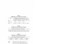
85025 Series Detector Descriptions . . . . . . . . . . . . . .
85025A/B/D/E Detector General Specications . . . . . . . . .
85025A Detector Specications (including Option 001) . . . . .
85025B Detector Specications . . . . . . . . . . . . . . . .
85025D Detector Specications . . . . . . . . . . . . . . . .
85025E Detector Specications . . . . . . . . . . . . . . . .
85025A/B/D/E Detector Supplemental Characteristics . . . . .
Equipment Required for Operator's Check . . . . . . . . . . .
Recommended Equipment . . . . . . . . . . . . . . . . . .
85025A/B Return Loss with Measurement Uncertainty . . . . .
85025D Return Loss with Measurement Uncertainty . . . . . .
85025E Return Loss with Measurement Uncertainty . . . . . .
Approximate Error Analysis at 18 GHz for 85025A/B/E Detectors
Approximate Error Analysis for the 85025D Detector . . . . .
85025A/B/D/E Replaceable Parts and Accessories . . . . . . .
Agilent 85025A/B/D/E
1-1
1-3
1-4
1-5
1-6
1-7
1-8
3-6
4-2
4-5
4-5
4-5
4-10
4-10
6-2
Contents-5
1
General Information
This manual contains information on operating, testing, and servicing the
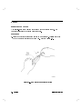
Agilent 85025A/B/D/E detectors. Figure 1-1 shows the detectors.
Product Description
The 85025A/B/D/E detectors are specically designed for use with Agilent 8757
series scalar network analyzers.
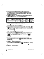
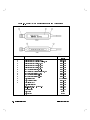
Table 1-1. 85025 Series Detector Descriptions
Detector
Connector Type
Frequency Range
85025A
85025A Option 001
85025B
85025D
85025E
Agilent 85025A/B/D/E
Type-N (m)
precision 7 mm
precision 3.5 mm (m)
precision 2.4 mm (m)
precision 3.5 mm (m)
.01 to 18 GHz
.01 to 18 GHz
.01 to 26.5 GHz
.01 to 50 GHz
.01 to 26.5 GHz
General Information
1-1
Figure 1-1. 85025A/B/D/E Detector
1-2
General Information
Agilent 85025A/B/D/E
Specications and
Supplemental Characteristics
Tables 1-2 through 1-6 list detector specications when used with an 8757
series scalar network analyzer. These specications represent the warranted
performance standards or limits against which you can test the device.
Table 1-7 lists supplemental (typical, non-warranted) detector characteristics,
when used with one of the above-mentioned analyzers.
Note
Specications describe the instrument's warranted performance
over the temperature range of 25 C, 65 C.
Table 1-2. 85025A/B/D/E Detector General Specications
Dynamic Range (on all 8757 Series analyzer's detector inputs):
AC mode
+16 to
DC mode
+16 to
Nominal Impedance
Maximum Input Power
Agilent 85025A/B/D/E
055 dBm
050 dBm
50
+20 dBm (100 mW),
610 VDC
General Information
1-3
Table 1-3.
85025A Detector Specications (including Option 001)
Frequency Range
Return Loss:
0.01 to 18 GHz
10 MHz to 40 MHz
10 dB
40 MHz to 4 GHz
20 dB
4 GHz to 18 GHz
17 dB
Frequency Response (in DC mode, input power 010 dBm):
10 MHz to 40 MHz
40 MHz to 18 GHz
00.75 dB
+0.25 dB/
60.5 dB
Absolute Power Accuracy (in DC mode, 50 MHz, calibrated at 0 dBm)
Dynamic Power Accuracy
1-4
General Information
Agilent 85025A/B/D/E
Table 1-4. 85025B Detector Specications
Frequency Range
Return Loss:
0.01 to 26.5 GHz
10 MHz to 40 MHz
10 dB
40 MHz to 4 GHz
20 dB
4 GHz to 18 GHz
17 dB
18 GHz to 26.5 GHz
12 dB
Frequency Response (in DC mode, input power 010 dBm):
10 MHz to 40 MHz
40 MHz to 18 GHz
00.75 dB
+0.25 dB/
60.5 dB
Absolute Power Accuracy (in DC mode, 50 MHz, calibrated at 0 dBm)
Dynamic Power Accuracy
Agilent 85025A/B/D/E
General Information
1-5
Table 1-5. 85025D Detector Specications
Frequency Range
Return Loss:
0.01 to 50 GHz
10 MHz to 40 MHz
10 dB
40 MHz to 100 MHz
20 dB
100 MHz to 14 GHz
23 dB
14 GHz to 34 GHz
20 dB
34 GHz to 40 GHz
15 dB
40 GHz to 50 GHz
9 dB
Frequency Response (in DC mode, input power 010 dBm):
10 MHz to 40 MHz
40 MHz to 20 GHz
20 GHz to 26.5 GHz
26.5 GHz to 40 GHz
40 GHz to 50 GHz
00.75 dB
60.5 dB
+1/00.5 dB
+2.5/00.5 dB
+3.0/00.5 dB
+0.25 dB/
Absolute Power Accuracy (in DC mode, 50 MHz, calibrated at 0 dBm)
Dynamic Power Accuracy
1-6
General Information
Agilent 85025A/B/D/E
Table 1-6. 85025E Detector Specications
Frequency Range
Return Loss:
0.01 to 26.5 GHz
10 MHz to 40 MHz
10 dB
40 MHz to 100 MHz
20 dB
100 MHz to 25 GHz
25 dB
25 GHz to 26.5 GHz
23 dB
Frequency Response (in DC mode, input power 010 dBm):
10 MHz to 40 MHz
40 MHz to 18 GHz
18 GHz to 26.5 GHz
00.75 dB
60.5 dB
60.5 dB at 18 GHz to 61.4 dB at 26.5 GHz
+0.25 dB/
Absolute Power Accuracy (in DC mode, 50 MHz, calibrated at 0 dBm)
Dynamic Power Accuracy
Agilent 85025A/B/D/E
General Information
1-7
Table 1-7.
85025A/B/D/E Detector Supplemental Characteristics
RF Connector Mechanical Tolerances:
Recession of the male center conductor from reference plane:
1
85025A
0.207 to 0.210 inches
85025A Option 001
0.000 to 0.003 inches
85025B
0.000 to 0.003 inches
85025D
0.000 to 0.002 inches
85025E
0.000 to 0.003 inches
Cable Length
Weight (Including cable):
1.22 m (48 inches)
Net:
0.24 kg (0.5 lb)
Shipping:
1.0 kg (2.2 lb)
Dimensions2 (Including input connector, not including cable)
1 Because a type-N gage calibration block zeros the gage at a 0.207-inch oset, the gage
displays a 0.207- to 0.210-inch oset as 0.000 to 0.003 inches.
2 The model used in this illustration is an 85025A. Because of varying input connector
lengths, the overall length measurements for the other detector models covered by this
manual are:
85025A Option 001: 5 3/16 inches
85205B: 5 1/8 inches
85025D: 5 1/4 inches
85025E: 5 7/16 inches
1-8
General Information
Agilent 85025A/B/D/E
Operating Environment
The detector will operate safely under the following conditions, but its
performance is not necessarily warranted. See the specications section for
more information.
Temperature: 0 to +55 C
Humidity:
Up to 95%. Protect the detector from temperature extremes
which can cause condensation.
Altitude:
Up to 4,572 m (15,000 ft)
Accessories
The detectors come with a 2-meter cable. A 25-foot and 200-foot cable can be
ordered separately. Table 6-1 lists the accessories that are available for use with
these detectors.
Storage and Shipment
To keep your detector in proper working condition, keep the following
suggestions in mind when storing or shipping it.
Environment
Store or ship the detectors in environments within the following limits:
Temperature: 025 to +75 C
Humidity:
Up to 95%. Protect the detector from temperature extremes
which can cause condensation.
Altitude:
Up to 4,572 m (15,000 ft)
Agilent 85025A/B/D/E
General Information
1-9
Packaging
Use containers and materials identical or comparable to those used in factory
packaging. If you ship the detector, follow these packaging instructions:
1. Wrap the detector in the original pouch and box. If they are not available,
wrap the detector in heavy paper and use a strong shipping container.
2. Provide a rm cushion that prevents movement inside the container. Use a
layer of shock-absorbing material around all sides of the detector.
3. Seal the shipping container securely.
4. Mark the shipping container FRAGILE.
Returning a Detector for Service
When you make an inquiry, either by mail or by telephone, refer to the detector
by both model number and full serial number.
If you ship the detector to an Agilent oce or service center, ll out a
blue service tag (provided at the back of this manual), and include the following
information:
1. Company name and address.
Do not use an address with a P.O. box number because products cannot be
returned to a post oce box.
2. The complete phone number of a technical contact person.
3. The complete model and serial number of the detector.
4. The type of service required (calibration, repair).
5. Any other information that could expedite service, such as failure condition
or cause.
1-10
General Information
Agilent 85025A/B/D/E
2
Installation
Refer to the following information when using the detector. Do not drop the
detector or subject it to excessive mechanical shock.
Initial Inspection
1.
2.
3.
4.
Check the shipping container and packaging material for damage.
Check that the shipment is complete.
Check connector, cable, and detector body for mechanical damage.
Check the detector electrically:
Either perform the operator's check in Chapter 3, \Operation," or make a
measurement in Chapter 4, \Performance Tests."
If any of the following conditions exist, notify your nearest Agilent oce:
Incomplete shipment.
Mechanical damage or defect.
Failed electrical test.
If you nd damage or signs of stress to the shipping container or the cushioning
material, keep them for the carrier's inspection. Agilent does not wait for a
claim settlement before arranging for repair or replacement.
Agilent 85025A/B/D/E
Installation
2-1
Electrostatic Discharge (ESD)
ESD can damage the highly sensitive circuits in this device; charges as low as
100 V can destroy a detector. ESD damage occurs most often as you connect or
disconnect a device. Use this detector at a static-safe workstation and wear a
grounding strap. Never touch the input connector center contacts or the cable
contact pins.
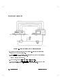
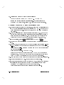
Static-Safe Work Station
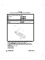
Figure 2-1 illustrates a static-safe station using two types of ESD protection that
you can use either together or separately:
A conductive table mat and wrist-strap combination.
A conductive oor mat and heel-strap combination.
Figure 2-1. Example of a Static-Safe Work Station
2-2
Installation
Agilent 85025A/B/D/E
Static-Safe Practices
Before cleaning, inspecting, or making a connection to a static-sensitive
device or test port, ground yourself as far as possible from the test port.
Discharge static electricity from a device before connecting it. Touch the
device briey (through a resistor of at least 1 M
) to either the outer shell of
the test port, or another exposed ground. This discharges static electricity and
protects test equipment circuitry.
Power Requirements
The scalar network analyzer supplies power for the detector.
Mating Connectors
Table 1-7 lists connector mechanical tolerances. Microwave Connector Care
(part number 08510-90064) provides information on the proper maintenance,
inspection, and gaging of connectors.
Connecting the Detector
1. The 85025A/B/D/E cables plug into the connectors on the front panel of the
8757 series scalar network analyzer. With the cable plug key downward,
insert the multi-pin (DC) connector into the A input on the front panel of the
analyzer.
2. To secure the DC connector in the analyzer, turn the outer shell clockwise.
3. Connect the RF input to the test device by turning the male connector's
outer shell clockwise.
Agilent 85025A/B/D/E
Installation
2-3
3
Operation
Caution
Agilent 85025A/B/D/E
Electrostatic discharge (ESD) can damage the highly sensitive
circuits in this device; charges as low as 100 V can destroy
your detector.
ESD damage occurs most often as you connect or disconnect
a device. Use this detector at a static-safe workstation and
wear a grounding strap. Never touch the input connector
center contacts or the cable contact pins.
Do not apply more than +20 dBm RF power or more
than 610 VDC to the detector. Higher power/voltage can
electrically damage the detector.
Before you connect a RF cable to the detector, always
discharge the static electricity that may have accumulated
on the cable's outer conductor to instrument ground. This is
most important if the cable is very long or connected to a
large antenna.
Do not drop the detector or subject it to mechanical shock.
Operation
3-1
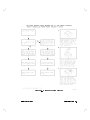
Features
Figure 3-1. Detector Features
Operating Theory
The 85025A/B/D/E can detect either unmodulated RF signals in DC mode or
square wave amplitude modulated RF signals in AC mode. In either AC or DC
detection mode, the detector provides a 27.778 MHz square wave signal for the
analyzer to interpret and display.
In AC detection mode, and RF or microwave signal is amplitude modulated
with a 27.778 MHz square wave. The detector demodulates (envelope detects)
this signal to produce a 27.778 MHz signal with a peak-to-peak voltage that
corresponds to the magnitude of the RF signal at the detector input.
In DC detection mode, no modulation is required. The detector diode in the
85025A/B/D/E converts the RF signal into an equivalent DC voltage. The
detector chops the DC voltage at a 27.778 kHz rate, and this chopped signal
is then amplied. The amplied signal simulates the signal produced by AC
detection.
3-2
Operation
Agilent 85025A/B/D/E
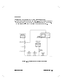
Measurement System Conguration
With an 8757 series scalar network analyzer using an 85025A/B/D/E detector,
system conguration requires special attention. AC mode is the default state
of the analyzer system and there are no further requirements to initiate a
measurement. However, to enable DC mode operation, a series of keystrokes is
required.
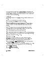
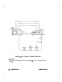
DC Detection mode
DC detection oers greater power measurement accuracy and the ability to
characterize oscillators and modulation-sensitive devices. Figure 3-2 depicts a
typical measurement setup for 0.01 to 50 GHz, using an Agilent 8350B sweep
oscillator/RF plug-in as the source.
1. On the analyzer, press 4PRESET5. Connect the detector(s).
2. DC detection mode must be selected. On the analyzer, press 4SYSTEM5 and
select MODE DC .
NNNNNNNNNNNNNNNNNNNNNNN
NNNNNNNNNNNNNNNNNNNNNNN
When the MODE DC softkey is selected, the source's square wave modulation
is automatically switched OFF.
Accurate DC Measurements
Zeroing the Detector
When you make DC detection measurements, it is important to perform this
detector zeroing procedure to compensate for the eects of DC drift and
temperature uctuations. This zeroing procedure eliminates small DC voltages
from the diode detector that would otherwise cause amplitude measurement
errors at low (40 dBm) power levels. Zeroing also establishes the displayed
noise level with no RF signal applied (the system's noise oor).
Autozero
NNNNNNNNNNNNNNNNNNNNNNN
Pressing the autozero softkey AUTOZRO switches OFF the source RF signal
output and automatically zeros the detector.
Agilent 85025A/B/D/E
Operation
3-3
NNNNNNNNNNNNNNNNNNNNNNNNNNNNNNNNNNNNNNNNNNNN
The repeat autozero function softkey ( REPT AZ ON/OFF ) periodically repeats
the autozero. You must use a GPIB interfaced sweeper to take advantage of this
function because the analyzer must be able to switch OFF the RF output of the
sweeper to perform the autozeroing.
Manual Zero
NNNNNNNNNNNNNNNNNNNN
Manual zero, represented by the MANUAL softkey, is similar to zeroing a power
meter.
1. Remove the RF signal from the detector's RF input.
2. On the analyzer, press MANUAL to perform the zeroing.
NNNNNNNNNNNNNNNNNNNN
Refer to \Operation," in the Agilent Technologies 8757C/E Scalar Network
Analyzer Operating Manual or Agilent Technologies 8757D Scalar Network
Analyzer Operating Manual for detailed information on these and other
softkeys.
In the DC mode, the 85025A/B/D/E is specied for absolute power level
accuracy. In regard to these specications, the following conditions apply:
The equipment has had a 30 minute warmup period.
The detector zeroing procedure has been performed.
The oset has been adjusted with a calibrated 0 dBm, 50 MHz signal applied.
Trace averaging is enabled on the analyzer at low power levels, as required.
The source harmonics are below 040 dBc.
The source SWR is 1.0.
To increase the accuracy of absolute power level measurements, select
DET OFFSET to properly set the system response to a 0 dBm signal. After
zeroing the detector, follow these steps to set the detector oset:
1. On the analyzer, press 4CAL5 DET OFFSET DET A (or the appropriate input
port). Press 405 4dB5. This ensures the 0 dB oset.
2. Connect the detector to the POWER REF output of a calibrated power meter,
such as an Agilent 436A or 438A. Switch the POWER REF output ON.
3. Press 4CURSOR5 AUTOSCALE .
NNNNNNNNNNNNNNNNNNNNNNNNNNNNNNNN
NNNNNNNNNNNNNNNNNNNNNNNNNNNNNNNN NNNNNNNNNNNNNNNNN
NNNNNNNNNNNNNNNNNNNNNNNNNNNNN
4. Press 4CAL5 MORE DET OFFSET .
NNNNNNNNNNNNNN NNNNNNNNNNNNNNNNNNNNNNNNNNNNNNNN
3-4
Operation
Agilent 85025A/B/D/E
5. Press DET A (or the appropriate input port) and use the entry keys to enter
the value opposite in sign to the cursor reading being displayed. The display
should now indicate a power reading of 0.00 dBm.
NNNNNNNNNNNNNNNNN
Note
Pressing 4PRESET5 on the analyzer does not reset any DC OFFSET
to zero, and the SAVE/RECALL registers do not save or recall
the oset value(s).
Figure 3-2. Typical System Setup for 0.01 to 50 GHz Measurements
Agilent 85025A/B/D/E
Operation
3-5
AC Detection Measurements
For the majority of measurements, AC detection is still the preferred method.
AC detection oers greater sensitivity and immunity to noise and drift across
time and temperature. AC detection amplitude measurements with this scalar
network analyzer system require a modulation envelope. This envelope is
provided through a 27.778 kHz square wave amplitude modulation of the RF
test signal. Test set connections vary depending on the source. Figure 3-2
depicts a typical measurement setup. The 27.778 kHz modulation is supplied by
the sweep oscillator.
Operator's Check
The following procedure provides a quick operational check of the
85025A/B/D/E detector.
Table 3-1. Equipment Required for Operator's Check
Description
Model/Part Number
Detector
GPIB cable
Bandpass lter
Sweep oscillator
85025A/B/D/E
10833A/B/C/D
any within the frequency range of the sweeper
any compatible with the 8757 series
scalar network analyzer
BNC cables (3 required) part number 8120-1839
3-6
Operation
Agilent 85025A/B/D/E
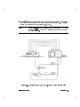
Procedure
Figure 3-3. Operator's Check Equipment Setup
1. Connect the equipment as shown in Figure 3-3, with the detector connected
to input A on the analyzer. Form a thru connection by connecting the
detector's RF input to the RF output of the source. Switch all of the
instruments' line powers ON and allow them to warm up.
2. If the 8757 series analyzer's system interface is not engaged (the analyzer's
status line displays SYSINTF OFF), press 4SYSTEM5 MORE SWEEP MODE
SYSINTF ON .
NNNNNNNNNNNNNN NNNNNNNNNNNNNNNNNNNNNNNNNNNNNNNN
NNNNNNNNNNNNNNNNNNNNNNNNNNNNNNNN
3. On the analyzer, press 4PRESET5. The analyzer's channel 1 should be active
and measuring input A.
4. Adjust the STOP and START frequencies on the source to include the
frequency range of the device under test (the bandpass lter).
Agilent 85025A/B/D/E
Operation
3-7
5. Switch OFF the analyzer's channel 2 by pressing CHANNEL 425 twice.
6. On the analyzer, press 4CURSOR5 MAX to place the cursor at the maximum
value of the trace. The CRSR value is displayed in the active entry area
of the analyzer. Adjust the output power of the RF plug-in until the
cursor value on the analyzer reads +16 dBm (this power level may not be
attainable on all sources). This value is the upper limit of the dynamic range
of the analyzer.
7. Press 4DISPLAY5 MEAS!MEM to store the trace in memory. The analyzer's
message line displays CHAN 1 MEAS TO MEMORY.
8. Disconnect the detector from the RF OUTPUT of the source. Press 4AVG5
AVG ON to activate the averaging function. The averaging value will be 8.
Wait a few seconds to allow the trace to settle.
9. Press 4CURSOR5 MAX . A cursor value of 055 dBm or lower should be
displayed in the active entry area. This value represents the noise oor
power level.
10. Insert the bandpass lter between the RF output of the source and the
detector. Wait a few seconds to allow the trace to settle.
11. Press 4CURSOR5 MAX to nd the trace maximum. The CRSR value displayed
in the active entry area now represents the minimum insertion loss of your
test device. Verify that the bandpass lter shape is as expected.
12. Press 4SYSTEM5 MODE AC/DC until the DC mode is activated. Allow the trace
to settle. The trace should look similar to the trace observed in step 11,
however the noise oor may be up to 5 dB higher. If the noise oor level
has increased more than 5 dB, zero the detector.
NNNNNNNNNNN
NNNNNNNNNNNNNNNNNNNNNNNNNNNN
NNNNNNNNNNNNNNNNNNNN
NNNNNNNNNNN
NNNNNNNNNNN
NNNNNNNNNNNNNNNNNNNNNNNNNNNNNNNN
If the Operator's Check Fails
Since the detector is measuring the output of an external source, problems may
be due to the source, rather than the detector. Verify that the source output as
well as the bandpass lter waveform are accurate. Note that bandpass lters
can vary considerably from unit to unit.
If the average noise oor is not below 050 dBm in DC mode, try zeroing the
detector. The instructions for zeroing the detector can be found earlier in this
chapter.
3-8
Operation
Agilent 85025A/B/D/E
4
Performance Tests
Use the procedures in this chapter to test the detector's electrical performance
to the specications listed in \General Information." None of these tests require
access to the detector's interior.
To completely test each detector, three tests are required:
1. return loss
2. frequency response
3. absolute power/dynamic accuracy
Note
For information on automating the Frequency Response
Performance Test, see the chapter titled \Program Listing."
Equipment Required
Preceding each test is a list that describes the equipment required to perform
that particular test. You may substitute any equipment that meets the indicated
critical specications. See Table 4-1 for an overall list of required equipment.
Note
Before you proceed with the performance tests, gage the
input connector on the detector and enter the results in the
Performance Test Record at the end of \Performance Tests."
For instructions on gaging the detector's input connector, see
\Detector Maintenance."
Agilent 85025A/B/D/E
Performance Tests
4-1
Table 4-1. Recommended Equipment
Description
Recommended Agilent Model
Equipment Common to all 85025A/B/D/E Detectors
Scalar network analyzer
Sweep oscillator
Power meter
8757C/D/E
8350B
436A, 437B, or 438A
RF plug-in
Power sensor
Directional bridge
Shielded open
Short
Adapter type-N(m) to type-N(m)
Attenuator
83592C
8481A
85027C
p/n 85032-20002
11511A
p/n 1250-1475
8491B Option 010
RF plug-in
Power sensor
Directional bridge
Calibrated open/short
Adapter type-N(m) to type-N(m)
Attenuator
83592C
8481A Option 001
85027A
p/n 85021-60001
p/n 1250-1475
8492A Option 010
RF plug-in
Power sensor
Directional bridge
Calibrated open/short
Attenuator
83595C
8485B
85027B
p/n 85037-60001
8493C Option 010
Equipment required for 85025A Detectors
Equipment required for 85025A Option 001 Detectors
Equipment required for 85025B Detectors
Equipment required for 85025D Detectors
Sweep oscillator
RF plug-in
Power sensor
Directional bridge
Open 2.4 mm(m)
Short 2.4 mm(m)
Adapter 2.4 mm(f) to 2.4 mm(f)
Attenuator
4-2
Performance Tests
8350B
83597B
8487A
85027D
85141A
85140A
11900B
8490D Option 010
Agilent 85025A/B/D/E
Table 4-1. Recommended Equipment (continued)
Description
Recommended Model
Equipment required for 85025E Detectors
RF plug-in
Power sensor
Directional bridge
Calibrated open/short
Attenuator
83595C
8485A
85027B
p/n 85037-60001
8493C Option 010
Return Loss Performance Test
This performance test uses an 8757C/D/E scalar network analyzer system to
measure the return loss of the detector.
85025A/B/D/E Return Loss Performance Test Procedure
Specications
Specications apply at a temperature range of 25 C 65 C. For the detector's
return loss specications, refer to Tables 1-2 through 1-6.
Description
The return loss of the 85025A/B/D/E can be measured using the test system
described in this procedure. The test setup is calibrated using an open/short to
minimize frequency response and phasing errors. The detector under test is
then connected to the TEST PORT of the bridge, and its return loss is measured
on the analyzer.
The return loss should be greater than the limits listed in Tables 1-2 through
1-6. There is a certain amount of measurement uncertainty in any scalar
network analyzer system. The return loss uncertainty for each detector is given
in Tables 4-2 through 4-4. Conformance to specication cannot be assured
unless the return loss of the detector is equal to the specied return loss
plus the measurement uncertainty. Failure to meet specication cannot be
proven unless measured return loss equals the specied return loss minus the
measurement uncertainty. The measurement uncertainty is based on the worst
case specications for the test devices in the measurement.
Agilent 85025A/B/D/E
Performance Tests
4-3
Example A:
The specied return loss for an 85025A detector at 1 GHz is 20 dB. The
measurement uncertainty is 61.4 dB.
If the detector's measured return loss is 20 dB +1.4 dB (21.4 dB or higher), the
detector is denitely within specication.
If the measured return loss is within the specied return loss plus-or-minus the
measurement uncertainty, the detector may or may not be within specication.
One way to reduce the measurement uncertainties is to measure the detector
using a vector network analyzer.
Example B:
If the 85025A in Example A measures 20 dB 61.4 dB (i.e. from 18.6 to 21.4 dB),
it cannot be determined if it is or is not within specication.
If the measured return loss is less than the specied return loss minus the
measurement uncertainty, the detector is denitely out of specication.
Example C:
If the 85025A in Example A and B measured less than 20 dB 01.4 dB (18.6 dB
or less), the detector is denitely out of specication.
The three main sources of error in these measurements come from:
Bridge directivity
Source match of the bridge
Dynamic accuracy of the analyzer
The rst two vary with frequency while dynamic accuracy varies with the
measured return loss amplitude.
Tables 4-2, 4-3, and 4-4 show measurement uncertainty for the 85025A/B,
85025D, and 85025E detectors, respectively. The tables assume you are using
the corresponding connector-compatible Agilent directional bridges. For
example, an 85027A bridge with an 85025A detector.
4-4
Performance Tests
Agilent 85025A/B/D/E
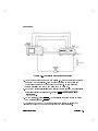
Return Loss Measurement
Figure 4-1. Setup for 85025A/B/D/E Return Loss Test
1. Connect the equipment as shown in Figure 4-1, leaving the directional
bridge TEST PORT unconnected.
2. Press 4PRESET5 on the analyzer. This will reset both the network analyzer
and the sweep oscillator (the source).
Allow 30 minutes for warmup.
3. On the source, press 4START5 4105 4MHz5 4STOP5 4405 4MHz5.
4. On the RF plug-in, press 4POWER LEVEL5 and adjust the output power with
the power level knob for a 03 dBm power level indication.
4-6
Performance Tests
Agilent 85025A/B/D/E
5. On the analyzer, press CHAN 2 OFF to switch channel 2 OFF. Press
FUNCTION 4MEAS5 A . Press FUNCTION 4REF5 REF POSN , then use the step
keys or the knob to move REF POSN one line down from the top of the CRT
graticule.
6. On the analyzer, press FUNCTION 4SCALE5 AUTO SCALE .
NNNNNNNNNNNNNNNNNNNNNNNNNNNNNNNN
NNNNN
NNNNNNNNNNNNNNNNNNNNNNNNNN
NNNNNNNNNNNNNNNNNNNNNNNNNNNNNNNN
Calibrating the Scalar Network Analyzer
7. On the analyzer, press FUNCTION 4CAL5 SHORT/OPEN . Follow the directions
(prompts) appearing on the CRT:
a. Connect the short to the TEST PORT of the directional bridge, then press
STORE SHORT on the analyzer. Remove the short.
NNNNNNNNNNNNNNNNNNNNNNNNNNNNNNNN
NNNNNNNNNNNNNNNNNNNNNNNNNNNNNNNNNNN
b. Connect the open to the TEST PORT of the directional bridge, then press
STORE OPEN on the analyzer. Remove the open.
NNNNNNNNNNNNNNNNNNNNNNNNNNNNNNNN
The CRT will display SHORT/OPEN CAL SAVED IN CH1 MEM.
8. Press FUNCTION 4DISPLAY5 MEAS-MEM .
NNNNNNNNNNNNNNNNNNNNNNNNNN
9. Connect the detector to be tested to the TEST PORT of the directional
bridge. On the analyzer, press FUNCTION 4CURSOR5 and turn the analyzer's
front panel knob to read the highest value (worst case return loss).
Record the worst case value in the space provided on the Performance Test
Record, located at the end of this chapter.
Return Loss from 40 MHz to 18 GHz (to 26.5 GHz for 85025B/E
only, to 50 GHz for 85025D only)
10. On the source, reset the START/STOP frequencies by pressing 4START5 4405
4MHz5. Next, for an 85025A detector, press 4STOP5 4185 4GHz5, for an 85025B/E
detector, press 426.55 4GHz5, or for an 85025D detector, press 4505 4GHz5.
11. On the analyzer, ensure FUNCTION MEAS POWER A is still active. Remove
the detector.
12. It will be necessary to recalibrate the analyzer, since a new range of
frequencies has been selected for measurement. Repeat the steps in the
section titled \Calibrating the Measurement System."
NNNNNNNNNNNNNNNNNNNNNNNNNNNNNNNNNNNNNN
Agilent 85025A/B/D/E
Performance Tests
4-7
NNNNNNNNNNNNNNNNNNNNNNNNNN
Ensure that channel 1 display MEAS-MEM is active. MEAS-MEM is
highlighted when active.
13. Connect the detector to the TEST PORT of the directional bridge.
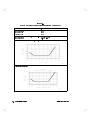
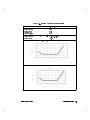
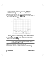
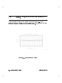
14. On the analyzer, press FUNCTION 4SCALE5 455 4dB5. The CRT display should be
somewhat similar to Figure 4-2.
Figure 4-2. 85025A/B/E Return Loss 0.04 GHz to Maximum Frequency
15. On the analyzer, press 4CURSOR5. Use the cursor to nd the highest trace
value in each specication range.
Note
A specication range is a range of frequencies which have
the same return loss specication. For example, the 85025A
specication from 0.4 to 4 GHz.
16. Record each value in the Performance Test Record.
This completes the 85025A/B/D/E return loss performance test procedure.
4-8
Performance Tests
Agilent 85025A/B/D/E
If This Test Fails
Check the detector's input connector to make sure there is no damage. Open
the detector's case and check the connection between the input connector and
the PC board. Check that the detector is connected securely to the front panel
of the analyzer. Replace the connector if necessary. If the detector still fails,
refer to the \Service" chapter for more troubleshooting information.
Frequency Response Performance Test
Description
The frequency response of the 85025A/B/D/E detector is specied as the
maximum peak-to-peak deviation from a constant input signal level of
010 dBm, as measured over the specied frequency range. At Agilent
Technologies, frequency response is measured with the use of an automated
test station traceable to the U.S. National Institute of Standards and Technology
(NIST).
The \frequency response" specication for the 85025 family of detectors may
more properly be called \frequency response atness." The test for frequency
response does not check absolute gain of the detector across its operating
frequency range. It checks the relative variations in gain across the operating
frequencies (for example, atness).
To simplify the measurement procedure, frequency response is measured
with a nominal 010 dBm signal applied. First, the source is characterized for
frequency response using a calibrated power meter/sensor combination. Next,
the DUT is characterized. Finally, a point-by-point dierence is computed,
plotted and compared to the specication window. Dierences in the values
recorded due to the dierent measurement scheme should be negligible.
The manual test described in this procedure has an approximate root sum of the
squares (RSS) uncertainty ranging from 60.19 dB to 60.37 dB for 85025A/B/E
detectors and 60.12 dB to 60.76 dB for 85025D detectors. This implies that a
\good" detector, well within the limits of its specications, could measure out of
specications.
This measurement is only an indication of the detector's response within these
limits. If greater measurement accuracy is desired, a test system that minimizes
Agilent 85025A/B/D/E
Performance Tests
4-9
the sources of measurement uncertainty will be required. An error analysis of
the sources of measurement uncertainty follows.
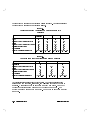
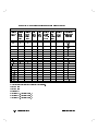
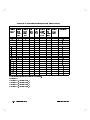
Table 4-5.
Approximate Error Analysis at 18 GHz for 85025A/B/E
Detectors
Uncertainty
85025A
Option 001
85025A
85025B
85025E
1.5%
1.5%
1.5%
1.5%
5.2%
3.8%
2.1%
2.4%
Mismatch between Attenuator and Detector
5.9%
4.2%
3.3%
1.5%
Miscellaneous System Errors
1.1%
1.1%
1.1%
3.2%
RSS Calculation
8.1%
6.0%
4.3%
Power Sensor CAL Factor Uncertainties
(RSS)
Mismatch between Attenuator and Power
Sensor
Total RSS Uncertainties Expressed in dB
+0.34 to
00.37
+0.25 to
00.27
+0.18 to
4.5%
00.19
+0.19 to
00.20
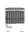
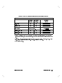
Table 4-6.
Approximate Error Analysis for the 85025D Detector
Uncertainty
Power sensor CAL factor approximate
26.5 GHz
40 GHz
50 GHz
1.5%
2%
2.5%
1.3%
3.8%
7.4
uncertainties
Mismatch between attenuator and power
Sensor
Mismatch between attenuator and detector
Miscellaneous system errors
RSS calculation
Total RSS uncertainties expressed in dB
1.4
4.2
14.3
1.1%
1.1%
1.1%
2.7%
+0.12 to
00.12
6.1%
+0.26 to
00.27
16.3%
+0.64 to
00.76
Uncertainties are smaller at lower frequencies. The error analysis is done
assuming the power sensor, attenuator, and DUT all mate without the use of
adapters. A standard 85025A is used with an 8481A and 8491B. An 85025A
Option 001 detector is used with an 8481A Option 001 and 8492A. The
85025B/E is used with an 8485A and 8493C. The 85025D is used with an 8487A
and 8490D.
4-10
Performance Tests
Agilent 85025A/B/D/E
Equipment Required
Equipment Common to 85025A/B/D/E
Sweep oscillator : : : : : : : : : : : : : : : : : : : : : : : : : : : : : : : : : : : : : : : : : : : : : : : : : : : : : : : : : : : : 8350B
Scalar network analyzer : : : : : : : : : : : : : : : : : : : : : : : : : : : : : : : : : : : : : : : : : : : : : : 8757C/D/E
Power meter : : : : : : : : : : : : : : : : : : : : : : : : : : : : : : : : : : : : : : : : : : : : : : : : : : : : : : : : : : : : : : : : 436A
Additional Test Equipment Required for 85025A
RF plug-in : : : : : : : : : : : : : : : : : : : : : : : : : : : : : : : : : : : : : : : : : : : : : : : : : : : : : : : : : : : : : : : : : 83592C
Power sensor : : : : : : : : : : : : : : : : : : : : : : : : : : : : : : : : : : : : : : : : : : : : : : : : : : : : : : : : : : : : : : : 8481A
10 dB attenuator : : : : : : : : : : : : : : : : : : : : : : : : : : : : : : : : : : : : : : : : : : : : : : 8491B Option 010
Additional Test Equipment Required for 85025A Option 001
RF plug-in : : : : : : : : : : : : : : : : : : : : : : : : : : : : : : : : : : : : : : : : : : : : : : : : : : : : : : : : : : : : : : : : : 83592C
Power sensor : : : : : : : : : : : : : : : : : : : : : : : : : : : : : : : : : : : : : : : : : : : : : : : : : : : : : : : : : : : : : : : 8481A
10 dB attenuator : : : : : : : : : : : : : : : : : : : : : : : : : : : : : : : : : : : : : : : : : : : : : : 8492A Option 010
Additional Test Equipment Required for 85025B
RF plug-in : : : : : : : : : : : : : : : : : : : : : : : : : : : : : : : : : : : : : : : : : : : : : : : : : : : : : : : : : : : : : : : : : 83592C
Power sensor : : : : : : : : : : : : : : : : : : : : : : : : : : : : : : : : : : : : : : : : : : : : : : : : : : : : : : : : : : : : : : : 8485A
10 dB attenuator : : : : : : : : : : : : : : : : : : : : : : : : : : : : : : : : : : : : : : : : : : : : : : : 8493C Option 010
Adapter, type-N(m) to 3.5 mm(f) : : : : : : : : : : : : : : : : : : : : : : : : part number 1250-1744
Additional Test Equipment Required for 85025D Only
RF plug-in : : : : : : : : : : : : : : : : : : : : : : : : : : : : : : : : : : : : : : : : : : : : : : : : : : : : : : : : : : : : : : : : : 83597B
Power Sensor : : : : : : : : : : : : : : : : : : : : : : : : : : : : : : : : : : : : : : : : : : : : : : : : : : : : : : : : : : : : : : 8487A
10 dB attenuator : : : : : : : : : : : : : : : : : : : : : : : : : : : : : : : : : : : : : : : : : : : : : : 8490D Option 010
Adapter, 2.4 mm(f) to 2.4 mm(f) : : : : : : : : : : : : : : : : : : : : : : : : : : : : : : : : : : : : : : : : : : 11900B
Agilent 85025A/B/D/E
Performance Tests
4-11
Additional Test Equipment Required for 85025E Only
RF plug-in : : : : : : : : : : : : : : : : : : : : : : : : : : : : : : : : : : : : : : : : : : : : : : : : : : : : : : : : : : : : : : : : : 83595C
Power Sensor : : : : : : : : : : : : : : : : : : : : : : : : : : : : : : : : : : : : : : : : : : : : : : : : : : : : : : : : : : : : : : 8485A
10 dB attenuator : : : : : : : : : : : : : : : : : : : : : : : : : : : : : : : : : : : : : : : : : : : : : : : 8493C Option 010
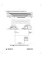
Adapter, 3.5 mm(f) to 3.5 mm(f) : : : : : : : : : : : : : : : : : : : : : : : : : part number 1250-1749
Figure 4-3. Frequency Response Measurement Setup
4-12
Performance Tests
Agilent 85025A/B/D/E
Specications
Specications apply at a temperature range of 25 C 65 C. For the detector's
return loss specications, refer to Tables 1-2 through 1-6.
85025A/B/D/E Frequency Response Performance Test
Procedure
Note
For 85025D detectors:
While the detector is specied down to 10 MHz, the power
sensor used in this procedure is only calibrated down to 50 MHz.
If data is required below 50 MHz, characterize the power sensor
to 10 MHz, or use an additional power sensor which covers this
frequency range, and correlate the results with the data above
50 MHz.
Conguring the System
1. Connect the equipment as shown in Figure 4-3, with nothing connected to
the attenuated output of the source. Switch ON all equipment and allow 30
minutes for warmup.
2. On the power meter, press 4dBm5 mode.
Zero and calibrate the power meter. If you are unsure of how to do this,
refer to the power meter's Operating and Service Manual.
4RANGE HOLD5 and 4POWER REF5 should remain out.
Set the CAL FACTOR % dial on the power meter to the value indicated for
50 MHz on the power sensor CAL FACTOR chart.
3. On the analyzer, press 4PRESET5 4CHANNEL5 CHAN 2 OFF INSTRUMENT STATE
4SYSTEM5 MODE DC .
NNNNNNNNNNNNNNNNNNNNNNNNNNNNNNNN
NNNNNNNNNNNNNNNNNNNNNNN
4. On the analyzer, zero the detector by pressing DC DET ZERO MANUAL CONT .
When the zero is complete, the display will indicate: MANUAL ZERO
COMPLETE.
5. Connect the power meter/sensor to the attenuated RF output.
6. On the source/RF plug-in, press 4CW5 455 405 4MHz5.
NNNNNNNNNNNNNNNNNNNNNNNNNNNNNNNNNNN NNNNNNNNNNNNNNNNNNNN NNNNNNNNNNNNNN
Agilent 85025A/B/D/E
Performance Tests
4-13
7. Adjust the power level for an indication of 010 dBm on the power meter.
Do not readjust the power level for the remainder of this test.
Characterizing the Source
8. On the source, press 4CW5 and enter the desired test frequency as indicated
on the Performance Test Record located at the end of this chapter. For
example: 4CW5 40.015 4GHz5.
9. Using the CAL FACTOR chart on the power sensor, set the CAL FACTOR %
dial on the power meter to the value indicated for the test frequency as
needed. Use the nearest frequency value.
10. Note the reading on the power meter.
11. Record this value and the test frequency in the Performance Test Record.
12. Repeat steps 9 and 10 until the source is characterized to your satisfaction.
Characterizing the Detector
13. Disconnect the power meter/sensor.
14. On the analyzer, zero the detector by pressing DC DET ZERO AUTOZRO .
When the zero is complete, the display will indicate: AUTOZERO COMPLETED.
15. Connect the detector between the attenuated output of the source and
INPUT A of the analyzer.
16. On the analyzer, press CHAN 2 OFF to switch channel 2 OFF. Press
FUNCTION 4CURSOR5 to switch the cursor ON.
17. On the source, press 4CW5 and enter the value of the rst test frequency.
Remember to use only the test frequencies used in steps 9 through 11.
Note the value indicated by the analyzer's cursor display and record it in
the Performance Test Record.
Repeat this step until all of the same frequency points have been
characterized.
NNNNNNNNNNNNNNNNNNNNNNNNNNNNNNNNNNN NNNNNNNNNNNNNNNNNNNNNNN
NNNNNNNNNNNNNNNNNNNNNNNNNNNNNNNN
Computing the Maximum Error
18. Using the values recorded in steps 11 and 17, subtract the value in step
11 from the value in step 17 for each of the test frequencies. Record the
dierence in the space provided on the Performance Test Record.
4-14
Performance Tests
Agilent 85025A/B/D/E
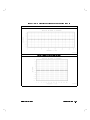
Now use these values to plot a point-to-point variation curve on the graph
provided in the Performance Test Record.
19. Read the \frequency response" limits from the appropriate specications
table in Chapter 1. Plot these limits onto the graph with the point-to-point
variation curve.
20. The detector is considered to \pass " this test if the variation curve is
contained within the limits, OR if an oset can be applied to the variation
curve so that it is contained within the limits. (In other words, can the
variation curve be shifted up or down to make it t within the limits?)
This completes the procedure for measuring frequency response.
Power Accuracy Performance Test
Specications
Refer to Table 1-2 through Table 1-6. Specications apply at 25 C 65 C.
Description
Power accuracy is measured with consideration given to the following
conditions (the order is not important):
Power accuracy is measured at 50 MHz.
If in DC mode, autozero has been performed (not necessary for AC mode).
All equipment has been allowed to warmup for 30 minutes.
Source harmonics are below 040 dBc.
This performance test includes mismatch eects. Specications assume no
mismatch.
Trace averaging should be used on the analyzer as required.
Oset active and adjusted with a calibrated 0 dBm, 50 MHz signal applied (DC
mode only).
The recommended method for testing power accuracy is to use an Agilent
8116A pulse/function generator as the source. An 8116A provides the amplitude
Agilent 85025A/B/D/E
Performance Tests
4-15
necessary to check the detector to its full specications. Both AC and DC modes
must be tested to verify the performance specications of the detector.
Note that the DC mode test is an \absolute" measurement, requiring the use of
a calibrated power meter to set a level of 0 dBm. Using the 436A as a calibrated
0 dBm, 50 MHz source introduces a maximum measurement uncertainty of
60.07 dB.
AC power accuracy testing is done with the 8116A modulated by an 11665B.
An alternate procedure is provided using an 8350B with an RF plug-in as the
source. This method does not test the detector to its full specications (tests to
+10 dBm) and should not be used when traceability to the National Institute of
Standards and Technology (NIST) is required.
Equipment Required
Pulse/function generator : : : : : : : : : : : : : : : : : : : : : : : : : : : : : : : : : : : : : : : : : : : : : : : : : : 8116A
Scalar network analyzer : : : : : : : : : : : : : : : : : : : : : : : : : : : : : : : : : : : : : : : : : : : : : : 8757C/D/E
50 MHz bandpass lter : : : : : : : : : : : : : : : : : : : : : : : : : : : : : : : : part number 08757-80027
3 dB attenuator : : : : : : : : : : : : : : : : : : : : : : : : : : : : : : : : : : : : : : : : : : : : : : : : : : : : : : : : : : : : 8491B
Calibrated 10 dB step attenuator : : : : : : : : : : : : : : : : : : : : : : : : : : 355D Option 001/H88
Calibrated 1 dB step attenuator : : : : : : : : : : : : : : : : : : : : : : : : : : : 355C Option 001/H88
Modulator (AC mode only) : : : : : : : : : : : : : : : : : : : : : : : : : : : : : : : : : : : : : : : : : : : : : : : : 11665B
Power meter (DC mode only) : : : : : : : : : : : : : : : : : : : : : : : : : : : : : : : : : : : : : : : : : 436A/438A
Adapters : : : : : : : : : : : : : : : : : : : : : : : : : : : : : : : : : : : : : : : : : : : : : : : : : : : : : : : : : : : : : : as required
Note
4-16
Calibrated attenuation is used in the power accuracy
calculations below. Calibrated step attenuators include a
calibration report at 50 MHz to improve measurement accuracy.
The report lists the actual attenuation of each step at one
frequency of interest. The calibration report may be ordered
as an option with the step attenuators when purchased or
performed as a service afterwards.
Performance Tests
Agilent 85025A/B/D/E
Procedure
Absolute Power Accuracy in DC Mode Performance Test
1. Connect the equipment as shown in Figure 4-4. Do not connect detector to
attenuator output. Do not use the modulator for this test (AC mode only).
Switch all the equipment ON and allow 30 minutes warmup time.
Figure 4-4. Absolute Power Accuracy Test Setup
Agilent 85025A/B/D/E
Performance Tests
4-17
2. For each of the power levels specied in columns 2 and 3 of the
Performance Test Record, record the required calibration data of the
step attenuators (10 dB step attenuator data in column 4 and 1 dB step
attenuator data in column 5).
3. Calculate the calibrated power level for each power level and record this
value in column 6 CAL PWR LVL. An example follows:
1. Nominal
PWR LVL
2. Nominal
10 dB STEP
ATTEN
3. Nominal
1 dB STEP ATTEN
4. CAL
ATTEN
5. CAL
ATTEN
6. CAL
PWR LVL
0
10
6
10.02
6.01
00.03
16 dBm 0(column 4 + column 5) = CAL PWR LVL
16 dBm 0(10.02 dB + 6.01 dB) = 00.03 dBm
4. On the 8116A, set a frequency of 50 MHz by pressing Sine Function 4P5 Duty
4DTY5. Using the VERNIER rocker keys adjust for a 50% duty cycle display.
Press Frequency 4FRQ5. Using the VERNIER and RANGE rocker keys adjust
for a 50 MHz display.
Select normal operation. LED NORMAL ON.
5. On the analyzer, press 4PRESET5 CHAN 2 OFF . Switch continuous wave ON
and select DC mode for the detector by pressing INSTRUMENT STATE
4SYSTEM5 MORE SWEEP MODE CW ON , INSTRUMENT STATE 4SYSTEM5
MODE DC .
NNNNNNNNNNNNNNNNNNNNNNNNNNNNNNNN
NNNNNNNNNNNNNN NNNNNNNNNNNNNNNNNNNNNNNNNNNNNNNN NNNNNNNNNNNNNNNNN
NNNNNNNNNNNNNNNNNNNNNNN
6. Congure the analyzer inputs and perform a manual DC zero.
NNNNNNNNNNNNNNNNNNNNNNNNNNNNNNNNNNNNNNNNN NNNNNNNNNNNNNNNNNNNNNNNNNNNNNNNNNNN
On the analyzer, press FUNCTION 4CAL5 CONFIG SYSTEM DC DET ZERO
MANUAL CONT .
NNNNNNNNNNNNNNNNNNNN NNNNNNNNNNNNNN
7. Perform the detector oset calibration.
On the analyzer, press DET OFFSET A 405 4dB5. This ensures 0 dB of oset.
NNNNNNNNNNNNNNNNNNNNNNNNNNNNNNNN NNNNN
8. Connect the detector to the power meter POWER REF output.
9. Switch POWER REF output ON.
4-18
Performance Tests
Agilent 85025A/B/D/E
10. On the analyzer, perform the following:
a. Press FUNCTION 4SCALE5 AUTO SCALE FUNCTION 4CURSOR5. Note the
reading for use in step b.
b. Press FUNCTION 4CAL5 DET OFFSET A . Using the ENTRY keys, enter the
value opposite in sign to the reading noted above.
Example: CRSR =+.45 dBm
Press 4-5 4.5 445 455 4dB5.
c. Press FUNCTION 4CURSOR5. The display should indicate a power
level of 0.00 dBm. If not, repeat the detector DC ZERO and OFFSET
CALIBRATION (steps 6 and 7) until a 0.00 dBm power level is obtained.
11. On the step attenuators, set the attenuators for a total of 16 dB attenuation.
Set the 355C to 6 dB and set the 355D to 10 dB.
12. Connect the DUT to the attenuated output.
13. On the 8116A enable the output by pressing 4DISABLE5. The DISABLE LED
should deactivate.
Refer to the Performance Test Record at the end of this chapter for the
calibrated power level computed at nominal 0 dBm. Use the VERNIER
rocker keys to adjust the output power to the CAL PWR LVL.
14. Note the cursor value displayed on the CRT. Record this value in the space
provided in column 7 of the Performance Test Record.
15. Set both attenuators to 0 dB attenuation. Note and record the cursor value.
16. Set the attenuators for the next Nominal PWR LVL (dBm).
NNNNNNNNNNNNNNNNNNNNNNNNNNNNNNNN
NNNNNNNNNNNNNNNNNNNNNNNNNNNNNNNN NNNNN
Note
For nominal power levels of 016 dBm and below, use a
combination of AVERAGING ON and SMOOTHING ON to
reduce trace noise and obtain a stable reading. Refer to the
Performance Test Record for the specied AVERAGING FACTOR.
Allow for settling time after resetting the attenuator(s).
17. When the cursor reading has stabilized, note and record the value in
column 7.
18. Repeat steps 13 and 14 for each nominal power level listed on the
Performance Test Record.
Agilent 85025A/B/D/E
Performance Tests
4-19
19. Calculate the Dynamic Accuracy Error as follows:
Dynamic Accuracy Error = MEAS PWR LVL 0 CAL PWR LVL
Include and preserve signs in this calculation. Enter this value in the
Dynamic ACCY Error (dBm), column 8, of the Performance Test Record.
Dynamic Accuracy in AC Mode Performance Test
20. Connect equipment as shown in Figure 4-4. Connect the modulator's DRIVE
INPUT to the analyzer's rear panel MODULATOR OUTPUT. Connect the DUT
to the attenuated output. Switch the equipment ON and allow 30 minutes
for warmup.
21. Record and calculate the data as necessary into columns 4, 5, and 6 of the
Performance Test Record. If the attenuators used in this test are the same
as the ones used in steps 2 and 3, copy the data from the Absolute Power
Accuracy in DC Mode Performance Test Record (columns 4, 5, and 6).
22. On the analyzer, press 4PRESET5 CHAN 2 OFF FUNCTION 4CURSOR5.
NNNNNNNNNNNNNNNNNNNNNNNNNNNNNNNN
23. Set the 10 dB step attenuator to 10 dB and set the 1 dB step attenuator to
6 dB.
24. On the 8116A, set a frequency of 50 MHz by pressing Sine Function 4P5 Duty
4DTY5. Using the VERNIER rocker keys adjust for a 50% duty cycle display.
Press Frequency 4FRQ5. Using the VERNIER and RANGE rocker keys adjust
for a 50 MHz display.
Select normal operation. LED NORMAL on.
Refer to the Performance Test Record for the CAL PWR LVL computed at
nominal 0 dBm. Use the VERNIER rocker keys to adjust the output power
to the CAL PWR LVL as displayed by the CURSOR on the analyzer.
25. Note and record on the Performance Test Record the cursor value displayed.
26. Set both attenuators to 0 dB. Note and record the cursor value.
27. Set the attenuators for the next Nominal PWR LVL. Continue the procedure
as outlined in steps 24 through 26 of the DC Mode Test for each of the
Nominal PWR LVLs listed on the Performance Test Record.
This completes the procedure for measuring dynamic accuracy.
4-20
Performance Tests
Agilent 85025A/B/D/E
Power Accuracy, Alternate Procedure Using an 8350B
(+10 dBm maximum)
Alternate Equipment
Sweep oscillator : : : : : : : : : : : : : : : : : : : : : : : : : : : : : : : : : : : : : : : : : : : : : : : : : : : : : : : : : : : : 8350B
RF plug-in : : : : : : : : : : : : : : : : : : : : : : : : : : : : : : : : : : : : : : : : : : : : : : : : : : : : : : : : : : : : : : : : : 83592B
Scalar network analyzer : : : : : : : : : : : : : : : : : : : : : : : : : : : : : : : : : : : : : : : : : : : : : : 8757C/D/E
50 MHz bandpass lter : : : : : : : : : : : : : : : : : : : : : : : : : : : : : : : : Part Number 08757-80027
3 dB attenuator : : : : : : : : : : : : : : : : : : : : : : : : : : : : : : : : : : : : : : : : : : : : : : : : : : : : : : : : : : : : 8491B
Calibrated 10 dB step attenuator : : : : : : : : : : : : : : : : : : : : : : : : : : 355D Option 001/H88
Calibrated 1 dB step attenuator : : : : : : : : : : : : : : : : : : : : : : : : : : : 355C Option 001/H88
Power meter (DC mode only) : : : : : : : : : : : : : : : : : : : : : : : : : : : : : : : : : : : : : : 436A or 438A
Adapters : : : : : : : : : : : : : : : : : : : : : : : : : : : : : : : : : : : : : : : : : : : : : : : : : : : : : : : : : : : : : : as required
Agilent 85025A/B/D/E
Performance Tests
4-21
Figure 4-5. Power Accuracy Alternate Test Setup
Procedure
1. Connect the equipment as shown in Figure 4-5. Allow 30 minutes warmup
time.
4-22
Performance Tests
Agilent 85025A/B/D/E
2. For each of the nominal power levels specied in the Performance Test
Record (Alternate Procedure), calculate the Calibrated Power Level. Refer
to steps 2 and 3 in the Absolute Power Accuracy in DC Mode Performance
Test for details. Change all +16 dBm references to +10 dBm.
Absolute Power Accuracy in DC Mode, Alternate Procedure
3. Do not connect the detector to the attenuated output.
4. On the analyzer, press 4PRESET5 CHAN 2 OFF INSTRUMENT STATE 4SYSTEM5
4MODE DC5. Next, press 4CAL5 CONFIG SYSTEM DC DET ZERO MANUAL CONT
DET OFFSET A 405 4dB5.
NNNNNNNNNNNNNNNNNNNNNNNNNNNNNNNN
NNNNNNNNNNNNNNNNNNNNNNNNNNNNNNNNNNNNNNNNN NNNNNNNNNNNNNNNNNNNNNNNNNNNNNNNNNNN NNNNNNNNNNNNNNNNNNNN NNNNNNNNNNNNNN
NNNNNNNNNNNNNNNNNNNNNNNNNNNNNNNN NNNNN
5. Connect the detector to the power meter POWER REF output.
6. Switch the POWER REF output ON.
7. On the analyzer, press 4SCALE5 AUTO SCALE 4CURSOR5. Note the reading.
NNNNNNNNNNNNNNNNNNNNNNNNNNNNNNNN
NNNNNNNNNNNNNNNNNNNNNNNNNNNNNNNN NNNNN
8.
9.
10.
11.
12.
13.
14.
On the analyzer, press 4CAL5 DET OFFSET A . Using the ENTRY keys, enter
the value opposite in sign to the reading noted above.
On the analyzer, press 4CURSOR5. The display should indicate a power level
of 0.00 dBm. If not, repeat the detector zero and oset calibration until a
0.00 dBm power level is obtained (steps 4 through 7).
Set the 10 dB step attenuator to 10 dB.
Connect the DUT to the attenuated output.
On the source, switch square wave modulation OFF. Set a CW frequency of
50 MHz.
Refer to the Performance Test Record for the CAL PWR LVL computed at
nominal 0 dBm. Adjust the output power to the CAL PWR LVL.
Note the cursor value displayed on the CRT. Record this value in column 7
of the Performance Test Record.
Set the attenuators for the next nominal PWR LVL. Continue the procedure
as outlined in steps 9 through 13 of the Absolute Power Accuracy in DC
Mode Performance Test for each of Nominal PWR LVLs listed on the
Performance Test Record (Nominal 055 dBm is for AC Test only).
Agilent 85025A/B/D/E
Performance Tests
4-23
Dynamic Accuracy in AC Mode, Alternate Procedure
15. Repeat steps 1 and 2 of Absolute Power Accuracy in DC Mode Performance
Test, Alternate Procedure. Connect the DUT to the attenuated output.
16. Preset the analyzer. Switch OFF channel 2. Switch ON the cursor.
17. Set the 10 dB step attenuator to 10 dB.
18. On the source set CW to 50 MHz.
19. Refer to the Performance Test Record for the CAL PWR LVL computed at
nominal 0 dBm. Adjust the output power to the CAL PWR LVL.
20. Note and record the displayed cursor value.
21. Set both attenuators to 0 dB. Note and record the cursor value.
22. Set the attenuators for the next nominal PWR LVL. Continue the procedure
as outlined in steps 17 through 19 of the Absolute Power Accuracy in DC
Mode Performance Test for each of the nominal PWR LVLs listed on the
Performance Test Record.
This completes the power accuracy alternate procedure.
4-24
Performance Tests
Agilent 85025A/B/D/E
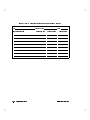
Performance Test Record
85025A/B/D/E Detector Performance Test Record (1 of 9)
Test Facility
Report Number
Date
Customer
Tested by
Model
Ambient temperature
Serial Number
Relative humidity
C
%
Options
Special Notes
Agilent 85025A/B/D/E
Performance Tests
4-25
85025A/B/D/E Detector Performance Test Record (2 of 9)
Model
Report Number
Test Equipment Used
Model Number
Date
Trace Number
Cal Due Date
1.
2.
3.
4.
5.
6.
7.
8.
4-26
Performance Tests
Agilent 85025A/B/D/E
85025A/B/D/E Detector Performance Test Record (3 of 9)
Test
Description
85025A/B Return Loss
Specication
Measured
Results
Measurement
Uncertainty1
10 MHz to 40 MHz
0.04 GHz to 4.0 GHz
4 GHz to 18 GHz
18 GHz to 26.5 GHz2
10 dB
20 dB
17 dB
12 dB
61.4 dB
61.1 dB
61.4 dB
61.1 dB
10 MHz to 40 MHz
0.04 GHz to 0.10 GHz
0.10 GHz to 14 GHz
14 GHz to 34 GHz
34 GHz to 40 GHz
40 GHz to 50 GHz
10 dB
20 dB
23 dB
20 dB
15 dB
9 dB
60.5 dB
+2, 05 dB
+3, 02 dB
+3, 02 dB
+2, 01.5 dB
+2, 01.5 dB
10 MHz to 40 MHz
0.04 GHz to 0.1 GHz
0.1 GHz to 25 GHz
25 GHz to 26.5 GHz
10 dB
20 dB
25 dB
23 dB
61.4 dB
61.1 dB
61.4 dB
61.1 dB
85025D Return Loss
85025E Return Loss
1 Using the equipment and procedures documented in this manual.
2 85025B only
Agilent 85025A/B/D/E
Performance Tests
4-27
85025A/B/D/E Detector Performance Test Record (4 of 9)
Test Frequency
Recommended
Actual
Frequency Response
Source
Step 11
Detector
Step 17
Dierence
Step 18
0.01 GHz
2.00 GHz
4.00 GHz
6.00 GHz
8.00 GHz
10.0 GHz
12.0 GHz
14.0 GHz
16.0 GHz
18.0 GHz
20.0 GHz
21.0 GHz
22.0 GHz
23.0 GHz
24.0 GHz
25.0 GHz
26.0 GHz
26.5 GHz
28.0 GHz
30.0 GHz
32.0 GHz
34.0 GHz
36.0 GHz
38.0 GHz
40.0 GHz
42.0 GHz
44.0 GHz
46.0 GHz
48.0 GHz
50.0 GHz
4-28
Performance Tests
Agilent 85025A/B/D/E
85025A/B/D/E Detector Performance Test Record (5 of 9)
85025A/B/E Absolute dB Error Versus Frequency
85025D Absolute dB Error Versus Frequency
Agilent 85025A/B/D/E
Performance Tests
4-29
85025A/B/D/E Detector Performance Test Record (6 of 9)
Absolute Power Accuracy in DC Mode
3.
4.
5.
6.
7.
8.
Nominal
CAL
CAL CAL PWR MEAS Dynamic
12 dB
ATTEN ATTEN LVL (dBm) PWR
ACCY
ATTEN (120 dB (12 dB (16 dBm - LVL
Error
Setting ATTN) ATTN)
CAL
(Cursor) (dBm)
(dB)
ATTN)
(dBm)
1.
Nominal
PWR LVL
(dBm)
2.
Nominal
120 dB
ATTEN
Setting
(dB)
0
10
6
16
0
0
REF
9.
Upper Limit1
( 85025A/B/D/E
unless noted
otherwise)
REF
2
3
2
0.61
3
0.76
0.70
1.0
13
0
3
10
0
6
0.52
6
10
0
0.40
3
10
3
0
10
6
03
10
9
0.40
06
20
2
0.40
010
20
6
0.40
013
20
9
0.40
30
2
0.40
30
6
0.40
40
1
0.40
40
6
0.40
50
1
0.40
50
6
0.70
60
1
1.0
60
6
1.3
0164
0204
0254 , 5
0304 , 5
0354 , 6
0404 , 6
0454 , 7
0504 , 7
0.40
REF
REF
1 Upper limit does not include measurement uncertainties.
2 85025A/B only
3 85025D/E only
4 Smoothing ON
5 Averaging ON, Averaging Factor=4
6 Averaging ON, Averaging Factor=8
7 Averaging ON, Averaging Factor=8
4-30
Performance Tests
Agilent 85025A/B/D/E
85025A/B/D/E Detector Performance Test Record (7 of 9)
1.
Nominal
PWR LVL
(dBm)
2.
Nominal
120 dB
ATTEN
Setting
(dB)
3.
Nominal
12 dB
ATTEN
Setting
(dB)
Dynamic Accuracy in AC Mode
4.
5.
6.
7.
8.
CAL
CAL CAL PWR MEAS Dynamic
ATTEN ATTEN LVL (dBm) PWR
ACCY
(120 dB (12 dB (16 dBm LVL
Error
ATTN) ATTN)
CAL
(Cursor) (dBm)
ATTN)
(dBm)
REF
9.
Upper Limit1
( 85025A/B/D/E
unless noted
otherwise)
0
10
6
16
0
0
REF
13
0
3
2
3
2
3
0.61 , 0.76
10
0
6
0.52
6
10
0
0.40
3
10
3
0.40
0.70 , 1.0
0
10
6
03
10
9
0.40
06
20
2
0.40
010
20
6
0.40
013
20
9
0.40
30
2
0.40
30
6
0.40
40
1
0.40
40
6
0.40
50
1
0.40
50
6
0.70
60
1
1.0
60
6
1.3
70
1
1.6
0164
0204
0254 , 5
0304 , 5
0354 , 6
0404 , 6
0454 , 7
0504 , 7
0554 , 8
REF
REF
1 Upper limit does not include measurement uncertainties.
2 85025A/B only
3 85025D/E only
4 Smoothing ON
5 Averaging ON, Averaging Factor=4
6 Averaging ON, Averaging Factor=8
7 Averaging ON, Averaging Factor=8
8 Averaging ON, Averaging Factor=32
Agilent 85025A/B/D/E
Performance Tests
4-31
85025A/B/D/E Detector Performance Test Record (8 of 9)
Alternate Tests
4.
5.
6.
7.
8.
CAL
CAL CAL PWR MEAS Dynamic
ATTEN ATTEN LVL (dBm) PWR
ACCY
(120 dB (12 dB (16 dBm - LVL
Error
ATTN) ATTN)
CAL
(Cursor) (dBm)
ATTN)
(dBm)
1.
Nominal
PWR LVL
(dBm)
2.
Nominal
120 dB
ATTEN
Setting
(dB)
3.
Nominal
12 dB
ATTEN
Setting
(dB)
0
10
0
10
0
0
0.52
6
0
4
0.40
3
0
7
0
10
0
03
10
3
0.40
06
10
6
0.40
010
20
0
0.40
013
20
3
0.40
016
20
6
0.40
020
30
0
0.40
30
5
0.40
40
0
0.40
40
5
0.40
50
0
0.70
50
5
1.0
60
0
1.3
60
5
1.6
60
6
1.3
70
1
1.6
0252
0302
0352 , 3
0402 , 3
0452 , 4
0502 , 4
0552 , 5
0502 , 5
0552 , 6
REF
9.
Upper Limit1
REF
0.40
REF
REF
1 Upper limit does not include measurement uncertainties.
2 Smoothing ON
3 Averaging ON, Averaging Factor=4
4 Averaging ON, Averaging Factor=8
5 Averaging ON, Averaging Factor=8
6 Averaging ON, Averaging Factor=32
4-32
Performance Tests
Agilent 85025A/B/D/E
85025A/B/D/E Detector Performance Test Record (9 of 9)
Connector
85025A
RF Input Connector Mechanical Tolerances
Minimum
Maximum
Recession
Recession
(inches)
(inches)1
0.207
2
Measured
Recession
(inches)
0.210
Type-N male
85025A Option 001
3
0.000
0.003
Precision 7 mm
Precision 7 mm
Collet must spring back out
Pass
Collet Resilience
after being depressed.
Fail
85025B/E
0.000
0.003
0.000
0.002
Precision 3.5 mm male
85025D
Precision 2.4 mm male
1 Minimum recession must NEVER be less than the minimum recession tolerance. If a connector
fails this specication, immediately replace it. Such connectors will damage any connector mated
to it.
2 The type-N gage calibration block zeros the gage at a 0.207 inch oset. Therefore, the 0.207 inch
to 0.210 inch recession is displayed as 0.000 to 0.003 inches on the gage.
3 With collet removed.
Agilent 85025A/B/D/E
Performance Tests
4-33
5
Adjustments
There are no adjustments which can be performed on the 85025A/B/D/E.
Agilent 85025A/B/D/E
Adjustments
5-1
6
Replaceable Parts
This chapter provides information on ordering replaceable parts. To order a part
listed in Table 6-1:
Quote the Agilent part number.
Indicate the quantity required.
Address the order to your nearest Agilent oce.
To request information on a part that is not listed in Table 6-1, include the
instrument model number, a description of the part, and its function. Address
the inquiry to the nearest Agilent oce.
How To Order Parts Fast
When you know which parts you need to repair the detector, contact Agilent
Technologies. The parts specialists have direct online access to the replacement
parts inventory corresponding to Table 6-1 in this guide.
Agilent 85025A/B/D/E
Replaceable Parts
6-1
Table 6-1. 85025A/B/D/E Replaceable Parts and Accessories
Item Number
Description
1
Replacement 85025A Detector, Type-N
85025-69018
1
Replacement 85025A Option 001 Detector, 7 mm
85025-69019
1
Replacement 85025B Detector, 3.5 mm
85025-69020
1
Replacement 85025D Detector, 2.4 mm
85025-69024
1
Replacement 85025E Detector, 3.5 mm
85025-69025
2
85025A Connector Repair Kit, Type-N
85025-60021
2
85025A Option 001 Connector Repair Kit, 7 mm
85025-60022
2
85025B Connector Repair Kit, 3.5 mm
85025-60023
2
85025D Connector Repair Kit, 2.4 mm
85025-60026
2
85025E Connector Repair Kit, 3.5 mm
3
Label, Serial Number
4
Label, Warning Max Input
85025-80001
5
Cable Assembly (W1)
85025-60003
Screw-Machine M2.5
85025-60027
Not Available
Cover, Plastic Half Body
6-2
Agilent Part
Number
2 0.45; 4 mm-LG
85025-40001
0515-0061
Washer-Lock 2.5 mm
2190-0583
Cable Marker Kit
5061-1044
Cable, 25 foot
11679A
Cable, 200 foot
11679B
Replaceable Parts
Agilent 85025A/B/D/E
Figure 6-1. Module Exchange Program
Agilent 85025A/B/D/E
Replaceable Parts
6-3
7
Service
Caution
This product is susceptible to damage from electrostatic
discharge (ESD). When you perform any of the following
procedures, wear a grounded static-strap and work at a
static-safe work station.
If the detector fails electrically, order a replacement detector. Do not order the
detector using its model number (85025A/B/D/E). Instead, use the replacement
part number given in Table 6-1 that is referenced to the model number.
These detectors have the following replaceable items:
The input connector.
The cable assembly.
Agilent 85025A/B/D/E
Service
7-1
Repair
Removing the Covers
A small at-blade screwdriver with a blade width no greater than 3.5 mm
(1/8 inch) is required to perform this procedure.
Procedure
1. Place the detector so its narrow side is on a at surface. Position it so that
the RF connector is facing away from you. Refer to Figure 7-1.
Figure 7-1. Removing the Detector Covers
7-2
Service
Agilent 85025A/B/D/E
2. Hold the sides of the detector near the cable-end. Insert the screwdriver at
a 45 degree angle between the side label and the raised edge of the plastic
cover as shown in Figure 7-1. Make sure the screwdriver is inserted as far
forward as possible on the detector.
3. Rotate the screwdriver about 90 degrees as shown, until the cover snaps
apart.
4. Repeat steps 2 and 3, inserting the screwdriver approximately 2/3 of the way
toward the cable-end of the detector, at the point shown in Figure 7-1.
5. Separate the plastic shell halves. If the cover does not separate easily, repeat
steps 2, 3, and 4 on the other side of the detector.
6. Attach the covers to the replacement detector by snapping the halves
together.
Replacing the Detector
1. Remove the plastic covers from the existing detector using the cover removal
procedure.
2. Install the covers on the replacement detector.
3. Perform the operator's check described in \Operation."
4. If using a restored exchange replacement detector, return the defective
detector using the packing material supplied. This should be done
immediately in order to assure proper credit for the exchange.
Note
If the existing plastic half cover is damaged or broken,
replacement covers are available. The part number is provided
in the replaceable parts list. Two are required for each detector.
Replacing the Cable Assembly
1. Order the cable assembly (Item 5 in Table 6-1).
2. Remove the outer covers using the cover removal procedure indicated
earlier in this section.
3. Remove the two pozi-drive screws located at the cable end of the metal
housing.
Agilent 85025A/B/D/E
Service
7-3
4. Slide the metal housing away from the RF connector to expose the printed
circuit (P.C.) assembly completely.
5. Carefully de-solder all cable wires from the P.C. assembly.
6. With the P.C. assembly facing up, secure the detector frame in a vice. Be
careful to set the detector so the P.C. assembly is NOT gripped.
Caution
Over-tightening the vice causes the frame to bend.
7. Use a 7/16-inch open-ended wrench to unscrew the cable hex nut.
8. Remove the old cable assembly and remove the metal housing from the
cable.
9. Carefully slide the metal housing onto the new cable assembly. Be sure to
place the metal housing so the adjustment potentiometers are accessible.
10. Screw the cable assembly onto the detector frame.
11. Solder the wires of the new cable to the P.C. assembly (refer to Figure 7-2
for proper placement).
12. Ensure that all cable wires are securely connected to the assembly.
13. Slide the metal housing over the P.C. assembly and secure to the frame
using pozi-drive screws.
14. Snap the outer covers back on.
7-4
Service
Agilent 85025A/B/D/E
Figure 7-2. Cable Connections
Replacing the Connectors
Order the appropriate Connector Repair Kit (see Table 6-1) for your detector.
Follow the instructions provided in the kit to replace the connectors.
Agilent 85025A/B/D/E
Service
7-5
8
Detector Maintenance
This chapter describes how to maintain your detector in proper working order.
This includes:
How to inspect the detector
How to clean the input connector
How to gage the input connector
Mechanical Inspection
This section provides a brief introduction to the fundamentals of proper
connector care, which is as important to making good measurements as proper
instrument calibration and adjustment.
This is not intended to be a comprehensive discussion of this vital topic. For
information on connector care, refer to the Microwave Connector Care Quick
Reference Card, part number 08510-90360.
Inspecting the Connectors
Visual and mechanical inspection of the connectors should be done periodically.
If a bad connector is accidentally attached to a good connector, the good
connector can be damaged. The time and expense involved in replacing
detectors or other devices due to damaged connectors warrants caution.
A connector is bad if one of the following conditions exist:
It fails the visual examination.
It fails the mechanical examination.
When attaching two connectors together, they do not mate smoothly.
Agilent 85025A/B/D/E
Detector Maintenance
8-1
Visual Examination
A careful visual inspection should be performed often on all system connectors.
Vigilance can save money and ensure accurate measurements with your
equipment.
Examine the connectors for such obvious problems as deformed threads,
contamination, or corrosion, concentrating especially on the contacting surfaces.
Look for burrs, scratches, rounded shoulders and similar signs of wear or
damage. Any problem you can see is sucient to cause degraded performance,
and the detector must be cleaned or replaced.
Cleaning the Connectors
In harsh environments, the connectors might become dirty. To safely clean the
connector, carefully brush or wipe dirt from the surface with a foam swab.
It is safe to use trichlorotriuoroethane (liquid Freon) sparingly as a cleaning
solvent. However, it is not safe to use abrasives of any kind (such as pencil
eraser) or any other solvent, because of damage to the thin metal plating or to
the plastic dielectric supporting element.
Connector Cleaning Kit
When cleaning an RF connector, Agilent recommends that you use the
Connector Cleaning Kit, part number 92193Z.
Gaging Connectors
Gaging connectors is necessary to ensure that they conform to mechanical
tolerances. Out-of-tolerance connectors have poor electrical performance and
could damage another connector mated to them. Refer to the Microwave
Connector Care Quick Reference Card, part number 08510-90360.
Refer to Table 1-7, \Supplemental Characteristics," for 85025A/B/D/E connection
tolerances.
8-2
Detector Maintenance
Agilent 85025A/B/D/E
Gaging Connectors to be Mated with the 85025A/B/D/E
It is important to gage connectors which will be used with the 85025A/B/D/E.
The specications for attaching connectors may vary, depending on the
connector used and the application. However, if the following guidelines are
used, you can avoid connector damage due to tolerance problems.
Type-N female
Gage any female device to be mated with the 85025A. When mated, a type-N
connector pair must have separation between the tip of the female contact
ngers and the shoulder of the male contact pin. Do not use female type-N
connectors that have an inner rubber washer, they damage the male center
conductor.
Precision 7 mm
Gage with the center conductor collet removed, refer to the tolerances given in
the device's manual. There should be no protrusion of the center conductor in
front of the outer conductor mating plane. Check the collet for proper spring
action. Collets should only be removed with a collet extraction tool. Refer to
the Microwave Connector Care Quick Reference Card for information.
Precision 3.5 mm female
Gage any female connector to be used with the 85025B/E. There should be
no protrusion of the tip of the female contact ngers in front of the outer
conductor mating plane.
Agilent 85025A/B/D/E
Detector Maintenance
8-3
9
Automated Program Listing
The information in this section is provided as a convenience only. It is intended
to provide a starting point for making automated measurements and does
not contain full error detection or extra enhancements. This program is not
warranted to be uninterrupted or error free.
Automating the Frequency Response Test
The program listing at the end of this chapter allows you to automate the
frequency response test of the detector. This test determines the frequency
response at up to 401 points in just a few minutes. The program rst measures
the frequency response of the source (taking into account the frequency
response of the power sensor), then measures the frequency response of the
detector, and nally plots the dierence between the two on the computer's
CRT. This is identical to the manual version of the test and the results should be
identical.
As written, this program will test detectors to 26.5 GHz. If you need results to
18 or 50 GHz, you must modify the START/STOP frequencies of the program.
The following equipment (.01 to 50 GHz) is recommended to run the program:
HP 9000 series 200 or 300 computer with BASIC 2.0 or above
A signal source: 83752A/B, 8360 Series, or 8350B with plug-in (depending on
the operating frequency of the detector you are testing)
Note
The 8360 Series and 83752A/B must rst be placed in network
analyzer language before running the program.
8757C/D/E scalar network analyzer
436A power meter with an appropriate power sensor
Agilent 85025A/B/D/E
Automated Program Listing
9-1
10 dB attenuator
Printer: (optional) for printouts; the printer must be capable of performing a
graphics dump.
Three GPIB cables (4 required if a printer is used): 10833A/B/C/D
GPIB is Agilent's hardware, software, documentation, and support for
IEEE-488 and IEC-625 worldwide standards for interfacing instruments.
There are two separate program listings:
Cal Factor Entry Program
Detector Frequency Response Program
Cal Factor Entry Program
The Cal (calibration) Factor Entry program allows you to input the calibration
factors listed on the power sensor. These cal factors are stored on a disc under
a le name that contains the power sensor serial number. This allows the
storage of cal factors for more than one power sensor. At the beginning of the
frequency response program, you are asked to input the serial number of the
power sensor. Only data for that power sensor is loaded into memory. Up to
50 cal factors can be stored in each le although less are shown on the power
sensors. A two-dimensional array is created containing combinations of a
frequency and its associated cal factor. This program need only be run once to
store the le on disc.
Running the Cal Factor Entry Program
The following information will help you successfully run the Cal Factor Entry
program.
When prompted, enter the last few digits of the power sensor serial number
(no more than 5 digits).
Enter the frequency in GHz, not MHz.
Enter both the frequency and the cal factor. For example, if the cal factor at
50 MHz is 99, enter .05,99 and press 4ENTER5.
Each entered frequency must be greater than the preceding frequency.
Fractional percentages are allowed (Example: 98.5).
If you make a mistake, back up the program by entering a negative frequency.
Each negative input backs up one entry and each entry must be input again.
9-2
Automated Program Listing
Agilent 85025A/B/D/E
When all cal factors are entered, enter 0,0 to exit. The program displays all of
the entered points. Verify the accuracy of each.
When you press 4CONTINUE5, the controller will store the le on disc. Make
sure the disc is not write protected.
Detector Frequency Response Program
The Detector Frequency Response program performs the Frequency Response
Performance Test using the cal factors previously stored on the disc. Any
number of frequency points, up to 401, may be chosen, although 101 points is
more than enough. The cal factor used is interpolated between the two closest
frequency points. The cal factor used for frequencies measured below the
lowest entered frequency point of the array defaults to the cal factor of the
lowest entered frequency point. A similar method is used at the high end.
To reduce the time required to copy these programs, the code listings represent
a minimum conguration to perform the measurement. There are no error
checking or convenience features. Be careful when entering data and when
following the displayed instructions.
Running the Detector Frequency Response Program
The following information will help you successfully run the Detector
Frequency Response program.
If not testing from .01 to 26.5 GHz, change the START/STOP frequencies in
lines 180/190 to the appropriate values.
When prompted, enter the last few digits of the power sensor serial number
(no more than 5 digits). Use the same power sensor serial number as in the
Cal Factor Entry program.
When prompted, enter the number of frequency points to be taken (no more
than 401). The data points will be evenly spaced across the frequency range.
When prompted, connect the calibrated power sensor to the attenuated
output of the source. The program automatically zeros the meter.
When prompted, remove the power sensor and connect the detector under
test to the attenuated output of the source. Connect the input cable of the
detector to the \A" input of the scalar network analyzer.
The program will ask if the test should be performed in AC or DC mode.
Normally DC mode is used for frequency response testing.
Agilent 85025A/B/D/E
Automated Program Listing
9-3
Note
If using DC mode, zero the detector before measuring the DUT
response.
A sample displayed output of the program is shown in Figure 9-1. If the
displayed frequency response exceeds the limits of the graph, increase the value
of \Scale" (variable controlling the scale size) in line 210.
Figure 9-1. Typical Program Output
9-4
Automated Program Listing
Agilent 85025A/B/D/E
Measurement Setup
Connect the equipment as shown in Figure 4-3. Connect the GPIB cables from
the controller to the GPIB inputs of both the power meter and scalar network
analyzer. Ensure that a system conguration and detector zero have been
performed.
The GPIB addresses are as follows:
Network analyzer: 716
Source: 19 (connected to the analyzer's System Interface Bus, not the
controller's GPIB)
Power meter: 713
A printer may be connected to the GPIB at address 701 if a printout is required.
The printer must be capable of performing a graphics dump.
Example Programs
The following programs can be used to automate the power meter CAL factor
entry and the Frequency Response Performance Test.
10
20
30
40
50
60
70
80
90
100
110
120
130
140
! POWER METER CAL FACTOR ENTRY PROGRAM
! Creates 2 dim array of freq (in MHz) vs cal factor
(in percent)
! Assigns a file name of "PM_xxxxx" (xxxxx is the pwr
sensor serial #)
!
OPTION BASE 0
DIM Cal(1:50,1:2)
INTEGER I,Pm_points
!
GRAPHICS OFF
PRINTER IS 1
OFF KEY
OUTPUT 1;CHR$(12)
BEEP 300,.1
INPUT "ENTER THE POWER SENSOR SERIAL # (LAST 5
DIGITS)",Serial
Agilent 85025A/B/D/E
Automated Program Listing
9-5
150
160
170
180
190
200
210
220
230
240
250
260
270
280
290
300
310
320
330
340
350
360
370
380
390
400
410
420
430
440
450
460
470
480
490
500
510
9-6
!
PRINT USING "3/,K,/";"ENTER BOTH FREQ AND CAL SEPARATED
BY A COMMA."
PRINT "ENTERING A NEG FREQ WILL BACK UP."
PRINT USING "3/,K,/";" #
FREQ
CAL%"
!
FOR I=1 TO 50 ! 50 POINTS MAX
Entry: !
BEEP 200,.02
DISP I;" Enter FREQ (in GHz) and CAL (in %). ""0,0
EXITS""";
INPUT "",Freq,Pct
IF Freq=0 OR Pct=0 THEN GOTO Done
Freq=Freq*1000
IF Freq<0 THEN
I=I-1
BEEP 1000,.02
GOTO Entry
END IF
IF I>1 THEN
IF Freq<=Cal(I-1,1) THEN
DISP "FREQ MUST BE GREATER THAN LAST ENTRY... TRY
AGAIN!"
BEEP 2000,.5
WAIT 2
GOTO Entry
END IF
END IF
Cal(I,1)=Freq
Cal(I,2)=Pct
PRINT USING "DD,3X,6D.D,5X,3D.D";I,Freq,Pct
NEXT I
!
Done: ! DISPLAY ENTERED VALUES
Pm_points=I-1
OUTPUT 1;CHR$(12)
PRINT USING "K,/,K,/";"
ENTERED VALUES"," #
FREQ
CAL%"
FOR I=1 TO Pm_points
PRINT USING "DD,3X,6D.D,5X,3D.D";I,Cal(I,1),Cal(I,2)
NEXT I
Automated Program Listing
Agilent 85025A/B/D/E
520 PRINT "Power Sensor serial number =";Serial
530 BEEP 400,.1
540 DISP "PRESS CONTINUE TO STORE DATA ON DISC."
550 PAUSE
560 !
570 DISP
580 ON ERROR GOSUB Error
590 ASSIGN @File TO "PM_"&VAL$(Serial)
600 OFF ERROR
610 OUTPUT @File;Pm_points,Cal(*)
620 ASSIGN @File TO *
630 BEEP 500,.02
640 DISP "CAL FACTORS HAVE BEEN STORED ON DISC."
650 CAT
660 STOP
670 !
680 ! **************************
690 Error: ! ERROR ON ASSIGNMENT
700 !
710 IF ERRN=56 THEN ! NO EXISTING FILE
720
CREATE BDAT "PM_"&VAL$(Serial),4 ! CREATE FILE
730
RETURN
740 END IF
750 DISP "ERROR # ";ERRN;" FIX, THEN PRESS CONTINUE"
760 BEEP 2000,.3
770 PAUSE
780 DISP
790 RETURN
800 END
Agilent 85025A/B/D/E
Automated Program Listing
9-7
10
20
30
40
50
60
70
80
90
100
110
120
130
140
150
160
170
180
190
200
210
220
230
240
250
260
270
280
290
300
310
320
330
340
350
360
370
380
9-8
! DETECTOR FLATNESS PROGRAM
! Plots detector measurements vs power meter measurements.
!
OPTION BASE 0
COM INTEGER Cal_data_flg
COM /Cal_f/ Cal(1:50,1:2),INTEGER Pm_points
COM /Measure/
Meas(1:401,1:3),Set_power,Start,Stop,Scale,INTEGER Points
COM /Hpib/ @Sna,@Source,@Pwr_mtr
!
GINIT
CALL Clear_screen
OFF KEY
ASSIGN @Sna TO 716
! Scalar Network Analyzer address
ASSIGN @Source TO 717 ! Passthrough address to Source
ASSIGN @Pwr_mtr TO 713 ! Power Meter address
!
! Change the below variables as needed for the detector under
test.
Max_points=401
Start=10
! Start frequency in MHz
Stop=26510 ! Stop frequency in MHz
Set_power=2 ! Power level set point of source in dBm
Scale=2
! dB (+/- graph limits)
!
IF NOT Cal_data_flg THEN ! get cal data on power sensor
DISP "ENTER THE POWER SENSOR SERIAL # (LAST 5 DIGITS)";
BEEP 700,.1
INPUT Serial
DISP "LOADING CAL FACTORS"
ASSIGN @File TO "PM_"&VAL$(Serial)
ENTER @File;Pm_points,Cal(*) ! Load cal factors
ASSIGN @File TO *
Cal_data_flg=1
DISP
END IF
BEEP 500,.1
DISP "ENTER NUMBER OF POINTS TO BE MEASURED
(";Max_points;"MAX)";
INPUT Points
Step_size=(Stop-Start)/(Points-1)
Automated Program Listing
Agilent 85025A/B/D/E
390
400
410
420
430
440
450
460
470
480
490
500
510
520
530
540
550
560
570
580
590
600
610
620
630
640
650
660
670
680
690
700
710
720
730
740
750
FOR I=1 TO Points
Meas(I,1)=Start+Step_size*(I-1)
NEXT I
REMOTE 7
OUTPUT @Sna;"IP PT19" ! preset system
CALL Set
LOOP
CALL Verify
BEEP 300,.1
DISP "
To repeat...press CONTINUE; to re-cal...RUN"
PAUSE
!
END LOOP
END
!
! ********** SUB PROGRAMS *************
!
SUB Corr_pwr(Freq,Power) ! uses cal factor to find actual
power read
COM /Cal_f/ Cal(*),INTEGER Pm_points
IF Freq<Cal(1,1) THEN ! freq too low, use first
value
Cal_factor=Cal(1,2)
GOTO Act_pwr
END IF
X=0
REPEAT
X=X+1
IF X>Pm_points THEN ! freq too high, use last value
Cal_factor=Cal(Pm_points,2)
GOTO Act_pwr
END IF
UNTIL Freq<Cal(X,1)
Frac=(Freq-Cal(X-1,1))/(Cal(X,1)-Cal(X-1,1))
Cal_factor=Frac*(Cal(X,2)-Cal(X-1,2))+Cal(X-1,2) ! cal
factor in %
Act_pwr:Power=Power-(10*LGT(Cal_factor/100))
! actual
power read
SUBEND
!
SUB Set ! finds freq response of source using pwr mtr as ref.
Agilent 85025A/B/D/E
Automated Program Listing
9-9
760
770
780
790
800
810
820
830
840
850
860
870
880
890
900
910
920
930
940
950
960
970
980
990
1000
1010
1020
1030
1040
1050
1060
1070
1080
1090
1100
1110
9-10
COM /Cal_f/ Cal(*),INTEGER Pm_points
COM /Measure/ Meas(*),Set_power,Start,Stop,Scale,INTEGER
Points
COM /Hpib/ @Sna,@Source,@Pwr_mtr
Clear_screen
OUTPUT @Sna;"MD0"
OUTPUT @Source;"MD0 CW PL-60DB RF0" ! works for 8350 or
8340/41
BEEP 400,.1
DISP "CONNECT POWER SENSOR TO ATTENUATORS"
PAUSE
!
CALL Zero_mtr
OUTPUT @Source;"PL";Set_power;"DB RF1 MD0 SV1 AM0 PM1" !
for 8350/40/41
FOR I=1 TO Points
OUTPUT @Source;"CW";Meas(I,1);"MZ"
IF I=1 THEN WAIT 5
Read_pwr(Meas(I,2))
Corr_pwr(Meas(I,1),Meas(I,2))
DISP USING 940;"Freq =";Meas(I,1);"MHz
Power
=";Meas(I,2);"dBm"
IMAGE
K,6D.D,K,3D.2D,K
NEXT I
DISP
Set_flg=1
SUBEND
!
SUB Clear_screen ! clears alpha and graphics screen
GRAPHICS OFF
OUTPUT 1;CHR$(12)
DISP
SUBEND
!
SUB Read_pwr(Power) ! reads power from 436A power meter @
100%
COM /Hpib/ @Sna,@Source,@Pwr_mtr
REPEAT
WAIT .3
OUTPUT @Pwr_mtr;"9D+T"
ENTER @Pwr_mtr USING "B,B,X,K";Sts,Range,Power
Automated Program Listing
Agilent 85025A/B/D/E
1120
1130
1140
1150
1160
1170
1180
1190
1200
1210
1220
1230
1240
1250
1260
1270
1280
1290
1300
1310
1320
1330
1340
1350
1360
1370
1380
1390
1400
1410
1420
1430
1440
1450
1460
1470
1480
1490
1500
1510
UNTIL Sts=80
SUBEND
!
SUB Zero_mtr
COM /Hpib/ @Sna,@Source,@Pwr_mtr
DISP "STAND-BY... zeroing power meter"
OUTPUT @Pwr_mtr;"A1+R"
WAIT 7
OUTPUT @Pwr_mtr;"Z1+R"
OUTPUT @Pwr_mtr;"9D+V"
WAIT 7
DISP
SUBEND
!
SUB Verify ! measures detector response
COM /Cal_f/ Cal(*),INTEGER Pm_points
COM /Measure/ Meas(*),Set_power,Start,Stop,Scale,INTEGER
Points
COM /Hpib/ @Sna,@Source,@Pwr_mtr
INTEGER I
Clear_screen
OUTPUT @Sna;"C2 C0 C1 IA ME FD0 MD1 SW0 AF1"
BEEP 500,.1
DISP "Select AC or DC mode. (A or D) Default = AC ";
INPUT Answ$
IF Answ$[1,1]="d" OR Answ$[1,1]="D" THEN
OUTPUT @Sna;"DM0 MD0"
ELSE
OUTPUT @Sna;"DM1 MD1"
END IF
BEEP 400,.01
DISP "CONNECT DETECTOR TO ATTEN AND TO INPUT ""A"" "
PAUSE
!
ALPHA OFF
Graticule
GRAPHICS ON
PEN 1
OUTPUT @Source;"PL";Set_power;"DB RF1"
FOR I=1 TO Points
OUTPUT @Source;"CW";Meas(I,1);"MZ"
Agilent 85025A/B/D/E
Automated Program Listing
9-11
1520
WAIT .3
1530
OUTPUT @Sna;"OV"
1540
ENTER @Sna;Meas(I,3)
1550
Db_err=Meas(I,3)-Meas(I,2)
1560
IF I=1 THEN MOVE Meas(I,1),Db_err
1570
PLOT Meas(I,1),Db_err
1580
NEXT I
1590 SUBEND
1600 !
1610 SUB Graticule ! generates graphics graticule
1620
COM /Measure/ Meas(*),Set_power,Start,Stop,Scale,INTEGER
Points
1630
GCLEAR
1640
DEG
1650
LDIR 0
1660
!
1670
! ** GRATICULE **
1680
X=Stop-Start
1690
Xmin=-.15*X
1700
Xmax=1.02*X
1710
Ymax=1.2*Scale
1720
Ymin=-1.5*Scale
1730
WINDOW Xmin,Xmax,Ymin,Ymax
1740
CLIP 0,X,-Scale,Scale
1750
FRAME
1760
LINE TYPE 3
1770
GRID 2000,Scale/5,0,0
1780
LINE TYPE 1
1790
AXES 1000,Scale/10,0,0,2,2
1800
CLIP OFF
1810
!
1820
! ** X-AXIS LABEL **
1830
CSIZE 4.3
1840
FOR I=INT(Start/1000) TO Stop STEP 4000
1850
LORG 6
1860
MOVE I,-Scale
1870
LABEL I/1000
1880
NEXT I
1890
!
1900
! ** Y-AXIS LABEL **
1910
CSIZE 4.
9-12
Automated Program Listing
Agilent 85025A/B/D/E
1920
FOR I=-Scale TO Scale STEP Scale/5
1930
LORG 8
1940
MOVE 0,I
1950
LABEL (INT(I*100+.5))/100
1960
NEXT I
1970
!
1980
! ** LABELS **
1990
CSIZE 5
2000
LORG 4
2010
MOVE (Stop-Start)/2,Scale
2020
LABEL "ABSOLUTE dB ERROR vs FREQ."
2030
LORG 6
2040
MOVE (Stop-Start)/2,-Scale*1.1
2050
LABEL "FREQUENCY in GHz."
2060
LDIR 90
2070
MOVE Xmin,0
2080
LABEL "dB ERROR"
2090 SUBEND
Agilent 85025A/B/D/E
Automated Program Listing
9-13
Index
A
adjustments, 4-33
C
cable
lead identication, 2-3
characteristics, supplemental, 1-7
connector
mating, 2-3
contacting Agilent, iv
D
detector
connecting, 2-3
replacing, 7-2
E
electrostatic discharge (ESD), 2-1
cautions, 3-1
F
oor mat
use, 2-2
H
heel strap
use, 2-2
I
initial inspection, 2-1
input connector
cleaning, 8-2
gaging, 8-2
installation, 1-10
M
maintenance, 7-5
cleaning the connectors, 8-2
gaging the input connector, 8-2
mechanical inspection, 8-1
visual inspection, 8-2
mat
use, 2-2
module exchange program, 6-3
O
operating environment, 1-9
ordering parts, 6-1
P
packaging, 1-9
parts, ordering, 6-1
performance test record, 4-25{33
absolute power accuracy response,
4-29
alternate power accuracy tests,
4-31
dynamic accuracy response, 4-30
frequency response, 4-27
input connector mechanical
tolerances, 4-32
performance tests, 3-8
equipment required, 4-1
frequency response, 4-9{15
Index-1
frequency response:computing
maximum error, 4-14
frequency response:detector
characterization, 4-14
frequency response:equipment
required, 4-11
frequency response:error analysis,
4-10
frequency response:procedure,
4-13, 4-15
frequency response:source
characterization, 4-14
frequency response:specications,
4-13
frequency response:system
conguration, 4-13
power accuracy, 4-15{24
power accuracy:absolute power in
DC mode, 4-17
power accuracy:alternate
procedure, 4-21
power accuracy:dynamic accuracy
in AC mode, 4-20
power accuracy:equipment
required, 4-16
power accuracy:procedure, 4-17
return loss, 4-3
return loss:failure, 4-9
return loss:procedure, 4-3{8
return loss:specications, 4-3
power
requirements, 2-3
product description, 1-1
program listing, 9-1
automated cal factor entry program,
9-2
automated frequency response test,
9-1
Index-2
R
example programs, 9-5
repair procedures, 7-2
removing the covers, 7-2
replacing the cable assembly, 7-3
replacing the detector, 7-3
replacing the input connectors,
7-5
replaceable parts, 6-1
replacing
detector, 7-2
return loss
test description, 4-3
S
service, 6-3
returning detector for service, 1-10
specications, 1-3{7
85025A (including Option 001), 1-4
85025B, 1-5
85025D, 1-6
85025E, 1-7
general, 1-3
static-safe
practices, 2-2
work station, 2-2
storage and shipment, 1-9
environment, 1-9
T
table mat
use, 2-2
W
wrist strap
use, 2-2