1
Product Training Guide
PDP-503CMX
Multimedia & Web Training Department
545 Nolan Drive Suite 100
Southlake, Texas 76092
Contents
Preface ……………………….…….. 3
New Functions…………………4-7
Basic Specifications.……………... 8
Controls & Connectors…………………41-45
New Features ….………………..…. 9-18
Normal Operation & Menu Modes……46-65
Main PCB layout………….…………19
Integrator Modes………………………...66-93
Overall Block………………..…20-21
Disassembly……………………………...94-97
Overview…………………………..…22
Factory Service Modes………………….98-132
Video Card………………………...…23-24
Adjustments……………………………..133-145
RGB Block……………………….…..25-28
Digital Video………………………...29-30
Y Drive…………………………….….31-32
X Drive…………………………….….33-34
Sub Address………………………...35-36
Resonance & Mid Clamp…….……37-38
Fan Drive/Audio…………………….39-40
PCB Locations………………………….146
Shut Down & Power Down……………147-155
RGB/Digital Video Replacement…….156-157
Preface
This technical training guide will address
the disassembly and adjustments of the
Pioneer PDP-503CMX Plasma Display.
This guide was designed as a servicing aid
and is not intended to replace the service
manual. The student should have the
appropriate service manual on hand when
when using this guide. Data in the service
manual for this unit contains specific
information on safety, parts and adjustments.
Safety information
Important safety data for this Pioneer model
is contained in the service manual. Before
returning the unit to the customer, complete
all product safety obligations and tests.
Technicians who bypass safety features or
fail to carry out safety checks may expose
themselves and others to possible injury,
and may be liable for any resulting damages.
For more information on electronic
circuits and block diagrams refer
to Service manual ARP3093
Lead in the solder used in this product
is a known reproductive toxicant which
may cause birth defects or other reproductive
harm. (California Health and Safety Code
Section 25249.5).
When servicing this or handling circuit
boards and other components which
contain solder, avoid unprotected skin
contact with the solder. Also, when
soldering do not inhale any smoke or
fumes produced.
3
List of New Functions
1. Out of Menu Mode
AUTO SET UP
• A function to adjust SCREEN mode automatically.
• The results of the adjustment is reflected on SCREEN value in Menu Mode.
• It functions only in case of PC signal input. (INPUT 1 or 2).
POINT ZOOM
• A function to magnify a display picture.
• The magnifying powers are 1.5 times, 2 times, 3 times, and 4 times
• When setting "POINT ZOOM", the picture size becomes "FULL mode".
• It functions only in the case of PC signal input.
Levels Display
• A function to display a setting content in OPTION menu.
• It displays by pressing the "DISPLAY CALL" key more than 2 sec. during an OSD display by usual DISPLAY CALL.
• Able to control this function using a new RS-232C command (DS2).
STILL
• A function to make a still picture from a present picture on the monitor.
• Able to set up using RS-232C command (SLY/SLN).
4
2. In Menu Mode
AUTO FUNCTION
• A function to switch to this input automatically, when a signal is
inputted to the input which was selected by this setting.
Automatically it goes back to previous input when there is no
input signal in the input.
• This function works only with “INPUT1” and “INPUT4”.
• For the “INPUT1”, this function works only with Composite
SYNC and Separate SYNC.
POWER CONTROL
• To switch the settings “Normal Display”, “Linear Brightness”, and
“Power Save”.
1. Normal Display : Almost the same as PDP-502 setting
“ABL ON”
2. Linear Brightness : Almost the same as PDP-502 setting
“ABL OFF”
3. Power Save
: New function from PDP-503
A function to lower the peak brightness
and lowers power consumption.
• Able to set up using RS-232C command (1: PWN / 2:PWS /
3:PWL)
PURECINEMA
• A function to convert 480i to 480P based on 2-3 pull-down data.
• There are three settings; OFF, STANDARD, and HQ.
• Able to set up input signal NTSC/480i only
• Able to set up using RS-232C command (PUN/PUS/PUH)
DIGITAL NR
• Setting up digital noise reduction.
• There are four settings; OFF, LOW, MIDDLE, and HIGH.
• It is effective only in the case of a VIDEO (NTSC) signal input.
• Able to set up using RS-232C command (NRN/NRL/NRM/NRH)
COLOR TEMP
• A function that changes setting of the colors TEMP.
• There are six settings: LOW (approx. –3000K), MID LOW
(approx. –2000K), MIDDLE(+/- 0K), MID HIGH(approx.
+1000K), HIGH(approx. +2000K)
• It is effective only in the case of a VIDEO (NTSC) signal input.
• Able to set up using RS-232C command
(CT1/CT2/CT3/CT4/CT5)
INPUT LABEL
• A function to change “INPUT LABEL” of each input.
• It is able to set up max. of eight letters.
5
3. Integrator Menu
OFF TIMER
• A function to switch to Stand-by mode after a set time.
• This setting has OFF,
TIMER (1 to 24H/ every 1H)
MASK (0.0 to 9.5 H/ every 0.5 H)
MASK Color (WHITE /RED / GREEN/ BLUE)
2 by 2 mode
• A function to make temporally 4 screen multi-display.
• This setting has ON or OFF and display area (upper left/ lower
left/ upper right/ lower left).
• Able to set up using RS-232C command (MGY/ MGN/ MG1/
MG2/ MG3/ MG4)
ORBITER
• A function to control burned display by shifting picture location
for every moment.
• The setting has ON or OFF
• Make the picture location shift one dot by one dot horizontally or
vertically every eight minutes.
• Able to set up using RS-232C command (OMY/OMN).
INVERSE
• A function to control burned display by reversing output picture.
• The setting has ON or OFF.
• Able to set up using RS-232C command.
ID SET
• A function to set or change ID No.
MONITOR NAME
• A function to register a name with each unit.
• Able to set max. of twelve letters.
• Able to confirm the name by Display Call/ GET command
HDTV Mode Setting
• A function to set actual line number in HDTV (1080i/1035i)
• Able to set this function when signal mode is “12/13”
• Able to set up using RS-232C command
(1080i=H80/1035i=H35)
6
4. Service Factory Menu
5. RS-232C
Displaying / Setting Pulse Meter
• A function to display or set the present pulse meter.
• The display is ten million unit
• The setting is hundred billion unit.
• Able to set up using RS-232C command.
Pulse meter display: PMD
Pulse meter setting: PMS+ XXX
Picture mute ON/OFF setting
• A function to set Picture MUTE on or off.
• No Last Memory function.
• MUTE is canceled when other operations are conducted.
• Able to set using RS-232C command only.
• It is effective in case of only Normal mode/ RS-232C adjustment
mode/ RS-232C factory adjustment mode.
Writing setting in EEPROM for Plug & Play use
• Releasing Write-protection of EEPROM for Plug & Play use.
• Able to set only in service factory mode and RS-232C factory
adjustment mode.
When it exits the above modes, it returns to Protect setting.
• Able to set up using RS-232C command.
Write protect release: EWY
Write protect setting: EWN
Drive ON / OFF Setting.
• A function to set Drive circuit on or off.
• There is no last memory function. (After turning off a unit, this
setting is canceled)
• Able to set using RS-232C command only.
• The command is effective only in Standby mode and RS-232C
factory adjustment mode.
100 % display mode setting 100%
• A function to change screen display into 100 % display.
• It functions only in case of VIDEO signal.
• All of menu modes are prohibited during this setting.
• Able to set up using RS-232C command only.
7
Basic Specification
PDP-502MX/MXE
(Current model)
PDP-503CMX
PDP-433CMX
Screen size
50inch
50inch
43inch
Aspect ratio
16:9
16:9
16:9
1280(H) 768(V)
1280(H) 768(V)
1024(H) 768(V)
Number of pixels
Pixel pitch
0.858 mm (RGB) 0.808 mm
Gradation
(256 gray scale)
Brightness
560cd/m2
0.858 mm (RGB) 0.808 mm
(768 gray scale)
800cd/m2
0.930 mm (RGB ) 0.698 mm
(768 gray scale)
800cd/m2
Contrast ratio
560:1
800:1
Viewing angle
H: More than 160°
H: More than 160°
V: More than 160°
V: More than 160°
H: More than 160°
V: More than 160°
4
2
2
Glass
Glass
MX: 100~120V 50/60Hz
MX: 100~120V 50/60Hz
MX: 100~120V 50/60Hz
MXE: 100~240V 50/60Hz
MXE: 100~240V 50/60Hz
MXE: 100~240V 50/60Hz
380W
TBD
Fan
Front filter
Power requirements
Acryl
Power consumption
470W
Effective screen size
1098mm 620.5mm
Dimensions
Weight
1218mm 714mm 98mm
40.3kg
1098 mm 620.5 mm
1218mm 714mm 98 mm
38.9kg
800:1
952.3 mm 536.1 mm
1070mm 630mm 98mm
Less than 30kg
8
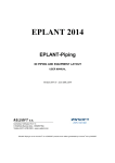
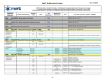
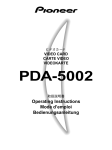
NEW Features/Benefits
• PDA-5002
– When installed it
adds Video, YC, and
DVI input, as well as
enabling High
Definition.
– Card manufactured
and supported by
Pioneer.
PDA-5002
9
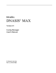
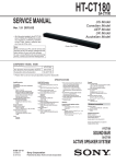
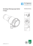
Rear View & Terminals
FAN
PDA-5002 (VIDEO CARD)
503CMX
RGB/BNC*5 In x1
RGB/D-Sub In x 1
RGB/D-Sub Out x1
Audio/Mini LR In x1
Audio/Mini LR Out x1
Speaker LR x1
Control
RS-232C/D-Sub 9 x1
SR/Mini In+Out x 1
Combi/Mini Din 6 In/O x1
PDA-5002
DVI-D In x1
YC/S VHS In x1
Composite/BNC In x1
Composite/BNC Out x1
Audio LR/RCA x2
10
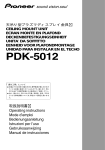
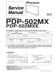
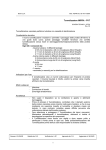
DVI-D interface for PDA-5002
There are two types of DVI interface; DVI-D and DVD-I. PDA-5002 has DVI-D input. Which
means this terminal can only accept Digital RGB signal.
Also the cable must be DVI-D cable.
(Yellow square)
11
DVI-I cable can not be used for PDA-5002.
Technical explanation on the new features.
- Higher luminance and contrast -
Higher luminance is realized by changing the cell structure.
2. Technical explanation on the new features.
- Higher luminance and contrast -
12
Deep Waffle Rib Structure: realises even higher light emission
efficiency
For the PDP-503, Pioneer’s further improved this technology
by making each individual cell deeper.
Deep Waffle Rib Structure
(Deep Encased Cell Structure)
The new cell structure has a greater light emission area, so this results in
even higher light emission efficiency—50% higher than our previous model .
(PDP-502)
13
PDP basic principles
The PDP screen is 2 glass panels with pixels sandwiched. The pixels consist of tiny
cells with electrodes on the top and bottom. Inert gas (Xenon+Neon) is trapped
between 2 glasses, separated by a gap of just 100-200 microns wide. UV light is
generated by discharging the gas using electrodes. Red, green and blue phosphors
absorb these UV discharges and reradiate the energy as visible light to produce the
colors that appear on the screen.
Sustain
electrode
Address
electrode
Pioneer Method
[B-C] Initialization discharge
(Reset) charges the electric at
+/- electrodes, activating
gas to extract electron
[F] Address discharge selects the cells
required for emission by clearing the
electric charge from unnecessary cells
with comparatively small voltage
[D] Sustaining discharge is made by a pulse of voltage on sustain electrodes. It
generates UV light, which makes phosphor radiate visible light emission.
[E] The electric at electrodes remains so that continuous pulses of AC voltage
can make another light-emitting discharge
14
Improvement of gradation reproduction in low brightness range
General PDP
New CLEAR drive system
12 steps
Input
256 steps (8bit Sub field method)
Output/ Brightness
Output/ Brightness
16
16 times
times
(lowest
(lowest 5%
5% range)
range)
Input
200 steps
768 steps (grayscale/ NTSC)
•Linear shaped characteristics of brightness level against input signal of conventional PDP is
poor at gradation in low brightness range
•Allocating comparatively more steps in low range, Characteristics of 503 has a gamma curve
similar to analog CRT, which doesn’t require the artificial process for offsetting gamma curve
15
of input signal in video processing
CLEAR driving method: the way to increase gradations
502MX:
12 sub-field x 2 (Field-to-field offset alternating) x 16 (Dither & Error dispersion) = 384 gradations
503CMX:
Output luminance level
PAL
PC
NTSC
Sub-field
13
10
12
Field-to-field offset alternating Dither & Error dispersion Total gradations
x2
x 32
= 832
x2
x 32
= 640
x2
x 32
= 768
1
1
1
Field-to-field offset
alternating
1st Field
2nd Field
Dither & Error
dispersion
0.5
0.5
0.5
0
0
0
6
12
0
0
12
Input Signal level
Each field (1/60 sec) can have 12 steps. (in case of NTSC)
With using 2 neighboring fields, different grayscales are
assigned. By combining these 2 fields, grayscales inbetween can be generated. As a result of it, another 12
steps can be implemented to get 2 times as many
grayscales as that of 1 field.
24
0
12
24
Dithering & Error dispersion
method realized by 10bit precise
calculation refines the analog-like
smooth gamma curve
16
Gradation Reproduction in Low Brightness Range
Pioneer’s CLEAR* driving technology has succeeded in eliminating
false contour of poor gradation areas. Details in shadow that were
previously obscured in conventional PDP can now be seen.
(*CLEAR: high-Contrast & Low Energy Address & Reduction of false contour
sequence. We alternatively call it “Continuous Emission Display Technology”)
Even with dark images, detailed patterns are faithfully reproduced.
Pioneer CLEAR drive
Conventional PDPs exhibit rough gradations in the low brightness
range, so image quality in dark areas is inferior. Pioneer’s gradation
slope is much smoother.
17
CLEAR sub-field driving method
Continuous Emission Display Technology
Grayscale
Reset Address Sustain
bright
BIT NOLSB 2BIT 3BIT 4BIT 5BIT 6BIT 7BIT 8BIT 9BIT 10BIT11BIT MSB
0
1
›
2
›
›
3
›
›
›
4
›
›
›
›
5
›
›
›
›
›
6
›
›
›
›
›
›
7
›
›
›
›
›
›
›
8
›
›
›
›
›
›
›
›
9
›
›
›
›
›
›
›
›
›
10
›
›
›
›
›
›
›
›
›
›
11
›
›
›
›
›
›
›
›
›
›
›
12
›
›
›
›
›
›
›
›
›
›
›
›
Continuous
light emission
Time (1/60 sec, NTSC)
•Only one reset discharge per field
•Continuous light Emission of the needed number of pulse
•No random light emission = No more random gaps without emission
Results :
•Higher Contrast (Lowest brightness less than 1cd/m2)
•Less Addressing power consumption: 1/3 vs 501
•No Dynamic False contour
High Contrast & Low Energy Address & Reduction of false contour sequence
18
Main PCB Layout PDP503CMX
Resonance Assy
Power Supply
Address Modules
Scan Modules
V-Mid Clamp PCB
X-Drive
Y-Drive
Audio Assy
Digital Video Assy
Address Modules
RGB Assy
Input Assy
Video Card
19
CLA1
DRIVER
IC
VADR2
DRIVER
IC
DRIVER
IC
ADDRESS CONNECT A
ASSY
AA1
Y4
PSU
VCC_VH
Y3
Y5
PSUS
Y6
DRIVER
IC
DRIVER
IC
VCP
Y-SUS
MASK
BLOCK
V_IC5V
VCP
Y-SUS
MASK
BLOCK
DRIVER
IC
CLK/LE
DC/DC
CONV
BLOCK
Drive
Signal
Y2
DRIVER
IC
RS-232C
232C
DRIVER
LOGIC
BLOCK
Drive
Signal
Combi
OUT
IC6901
BUFFER IC
DRIVER
IC
Y1
DRIVER
IC
IC6501
BUFFER IC
DRIVER
IC
TE1
THERMAL SENSOR
ASSY
Combi
IN
CLK/LE
+5V
V_OFS VCC_VH V_IC5V
VC_VFVC_VF+
+5V +15V VSUS
+15V VSUS
IC2206
Pulse Module
+5V +15V VSUS
+RESET Block
IC2204
Pulse Module
+15V
SOFT-D
BLOCK
VC_VF- V_OFS
V_IC5V
OFFSET
BLOCK
DRIVER
IC
SR OUT
CONTROL ASSY
Photo Coupler
BLOCK
VC_VF+
Y DRIVE ASSY
V_IC5V VCC_VH
Scan Signal
SR IN
C3
AD1
DRIVER
IC
C1
BGA1
DRIVER
IC
+12V
12V
TEMP
DRIVER
IC
VADR2
DRIVER
IC
CLAMP
DRIVER
IC
DRIVER
IC
V+5V_ST
BA2:9
BB2:9
GA2:9
GB2:9
RA2:9
RB2:9
DRIVER
IC
DRIVER
IC
9V,±5V,
3V
T1
DRIVER
IC
CLK/LE
R2
BA2:9
BB2:9
GA2:9
GB2:9
R3
RA2:9
RB2:9
DRIVER
IC
DRIVER
IC
IC6601
BUFFER IC
Switching
Q115
STB5V
SEL
DRIVER
IC
DRIVER
IC
SAA2
ADR_CO
SAA3
K1
Q6706 to Q6711
VADR_GEN
SAA1
+60
VSU
T
Switching
POWER SUP
T104
VSUS
R9
P6
+60
SAB
R
3ST
RE
+3V
REG
+3V,+5V
IC4
A/D PL
IC5601
WIDE UCOM
STB+5V
P5
Switching
Q119
T103
VADR
R4
3State Buffer
R6
ADR_C
IC5001(IC102)
T3
Audio
OUT
SAB2
SAB3
K1
Q6706 to Q6711
VADR_GEN
DRIVER
IC
DRIVER
IC
ADR RESONANCE ASS
K2
Audio
IN
K2
DRIVER
IC
VADR2
T101
Switching
Q117
P2
SD RAM
16M
T2
VADR2
DRIVER
IC
INPUT 1/2/5
IC5102(IC101)
DRIVER
IC
T6
+3V,+2V
T102
ADR RESONANCE
ASSY
+15V
+12V
+13.5V
+6.5V
-9V
P1
SD RAM
16M
IC5301(IC30)
RGB ASSY
SD RAM
16M
SD RAM
16M
+3V,+5V,-5V,+9V
SEL
Component/
RGB
INPUT 2
12V,13.5V,
-9V,6.5V
DRIVER
IC
IC6881
BUFFER IC
IN1 DET
12V,
STB5V
T5
12V,13.5V,-9V,
6.5V,STB5V
INPUT 1
DRIVER
IC
CLK/LE
OUTPUT
13.5V,6.5V,-9V
DRIVER
IC
AC1
Component/
RGB
Plug&Play
E2PROM
REG
12V,9V,±5V,3V
T4
V+3V
V+2V
AB1
ADDRESS CONNECT B
ASSY
V+5V_
D16
V+3V
V+2V
KL_U0:2
XDRV_SIG
ADL_LE_DL
ADL_LE_UL
V+3V_ V+2V_IC
V+3V_
IC119
FLASH
ROM
V+3V_
IC1101
PANEL UCOM
D17
DRIVER
IC
ADDRESS CONNECT C
ASSY
D13
DRIVER
IC
TXD0/RXD0
RE
LED_SIG
I2
IC1301(IC31 L)
SUB-FILD CONV.
for LEFT with FILD MEM.
CLK GEN
X180
V+3V
DIGITAL ASSY
DC-DC CONVERTER
MODULE
D9
BRIDGE A
ASSY
+12
V+3V
IC1703
XY DRV SEQUENCE
PATTERN GEN.
YDRV_SIG
SCAN_SIG
V+3V_I V+2V_I
C
TXD/RX
DRIVER
IC
CLAMP
ADLCLK_DR
V+5V_STB
D12
IC120
MODULE
UCOM
BRIDGE C
ASSY
BGC1
DRIVER
IC
VADR2
DRIVER
IC
VADR2
IC1401 (IC31
SUB-FILD CONV.
For RIGHT with FILD MEM.
V+5V_STB
D8
VADR2
DRIVER
IC
Overall BLOCK DIAGRAM
DRIVER
IC
CLAMP
SCAN
VCC_VH
VCC_VH
VCC_VH
VCC_VH
VCC_VH
VCC_VH
PSUS
SCAN
VCC_VH
VCC_VH
VCC_VH
VCC_VH
VCC_VH
PSUS
VCC_VH
SCAN A ASSY
(UPPER)
IC5
IC6201
ADD
SEL_PULSE
IC5
IC6202
ADD
SEL_PULSE
IC5
IC6203
ADD
SEL_PULSE
IC5
IC6204
ADD
SEL_PULSE
IC5
IC6205
ADD
SEL_PULSE
IC5
IC6206
ADD
SEL_PULSE
IC5
IC6001
ADD
SEL_PULSE
IC5
IC6002
ADD
SEL_PULSE
IC5
IC6003
ADD
SEL_PULSE
IC5
IC6004
ADD
SEL_PULSE
IC5
IC6005
ADD
SEL_PULSE
IC5
IC6006
ADD
SEL_PULSE
SCAN B ASSY
(LOWER)
KL2
SPR1
L OUT
SP OUT R
ASSY
SIDE KEY
ASSY
KEY CONNECTOR
ASSY
KL1
VADR2
DRIVER
IC
DRIVER
IC
ADDRESS CONNECT D
ASSY
CLAMP C ASSY
RE1
IR
ASSY
SW1
CLAMP A
ASSY
CLC1
CLAMP
DRIVER
IC
20
R
2
o
K2
DRIVER
IC
BLOCK DIAGRAM
DRIVER
IC
K3
DRIVER
IC
VADR2
LIVE
DRIVER
IC
RC101
PRIMARY
NEAUTRAL
SUB ADDRESS A
ASSY
M111
Q122
SECONDARY
POWER(RELAY)
STB5V
P3
R1
S2
DRIVER
IC
Audio
IN3 DET
SECAM
FLT
P4
DRIVER
IC
RL101
STB+5V
12V,5V
IC4803
PLD for SYNC
DRIVER
IC
IN4 DET
DRIVER
IC
DRIVER
IC
IC6801
BUFFER IC
Temp3
Audio_NG
FAN_NG
A5
+15V,+5VSTB
A1
A_Mute2
R_Audio
L_Audio
IC6601
BUFFER IC
BGB1
DRIVER
IC
VADR2
DRIVER
IC
VM2
V MID CLAMP
ASSY
V MID CLAMP U
FAN_Mute
+15V
DRIVER
IC
VADR2
DRIVER
IC
CLAM
A3
L_OUT
R_OUT
+5VSTB
A7
A6
FAN_D
BRIDGE B
ASSY
CLAMP
DRIVER
IC
DRIVER
IC
VADR2
DRIVER
IC
X1
X2
DRIVER
IC
DRIVER
IC
V_RN
DC/DC
CONV
BLOCK
Drive
Signal
+5V
AD1
LOGIC
BLOCK
Drive
Signal
DRIVER
IC
DRIVER
IC
V_SUS +5V +15V
DRIVER
IC
+15V
+15V
IC3200
Pulse
Module
V_RN
+Reset
Pulse
Block
IC3201
Pulse
Module
V_SUS +5V
AA1
DRIVER
IC
X DRIVE ASSY
DRIVER
IC
ADDRESS CONNECT A ASSY
BRIDGE D ASSY
L1
MX LED ASSY
D.C Det
IC8701
REGULATOR
IC8601
POWER AMP
L OUT
DRIVER
IC
VADR2
DRIVER
IC
BGD1
SP OUT L
ASSY
SPL1
+15V
V MID CLAMP L
VM1
Audio
Mute
OP-AMP(Buf)
+5V_AD/RGB
MX AUDIO ASSY
ADDRESS CONNECT C
ASSY
CLK/LE
R8
I2C-BUS
Expander
CLK/LE
DRIVER
IC
DRIVER
IC
ADDRESS CONNECT B ASSY
VIDEO SLOT
ST1 ASSY
DRIVER
IC
OUTPUT
AWV1906 Only
SD RAM
3D Y/C
&CNR
6M LPF
E2PROM
SLOT CONNECTOR
ASSY
AB1
DRIVER
IC
INPUT4
Composite
SEL
6M LPF
3L Y/C
6MLPF
IC7302
CHROMA DECODE (4-1SEL)
S3
6M LPF
MATRIX
I2C-BUS
IC5505
MAIN UCOM
SEL
S-Video
INPUT3
Audio
VADR2
AC1
OVERALL BLOCK DIAGRAM
DRIVER
IC
SAA2
ADR_CO
SAA3
K1
Q6706 to Q6711
VADR_GEN
SAA1
+60
Switching
T105
FLASH
ROM
+7V
+7V,-8V
S1
STB+5V
M114
VSUS_CONT
REG
REG
+3V,+5V
3STATE Buffer
IC7401
TMDS
Receiver
DVI-D
K3
DRIVER
IC
DRIVER
IC
SUB ADDRESS B
ASSY
INPUT 5
SAB1
DRIVER
IC
T105
POWER SUPPLY MODULE
T104
VSUS
R9
P6
+60
+3V,+5V,-5V V1
IC4603
A/D PLL AMP
IC5601
WIDE UCOM
STB+5V
P5
Switching
Q119
T103
VADR
R4
3State Buffer
R6
ADR_C
IC5001(IC102)
T3
Audio
OUT
SAB2
SAB3
K1
Q6706 to Q6711
VADR_GEN
DRIVER
IC
ADR RESONANCE ASSY
ER
CLK/LE
DRIVER
IC
DRIVER
IC
DRIVER
IC
VADR2
DRIVER
IC
VADR2
DRIVER
IC
CLB1
DRIVER
IC
CLD1
CLAMP D ASSY
X CONNECTOR
B ASSY
X CONNECTOR
A ASSY
CLAMP B
ASSY
IC6901
BUFFER IC
P_SUS
X3
P_SUS
X4
IC6501
BUFFER IC
DRIVER
IC
ADDRESS CONNECT D
ASSY
VCP
X_SUS
MASK
VCP
X_SUS
MASK
CLK/LE
DRIVER
IC
21
CLAMP
CLAM
Overview PDP-503CMX.–
*Component in
with PDA-5002
IN3 S in
(Din6p)
IN4 C.Vin
(BNC)
IN5 DVI-Din
YCbCr
RGB
HV
Audio
SLOT Connect Assy
(AWZ6634)
* Slot card interface
Video slot Assy, PDA-5002
(AWV1906)
* IN3/4 Terminals
* IN3/IN4 input select
* YC seap
* Color decoder
* DVI-D terminal, TMDS
decoder
IND assy
(AWZ6642)
* LED
Side SW assy
(AWZ6637)
* Key SW
STB
+5V
AC IN
PWR On/Off
PD cont
TH Sensor assy
(AWZ6639)
* Thermal sense
Temp1
SP out assy L/R
* Terminal
* Thermal sense (L)
X DRV Data
Reso data
Sub ADR A Assy
(AWZ6646)
*Adr Fault det
Adr Data
Key
Tx/Rx
Rem
Key cont assy
(AWZ6638)
* Key matrix
decoder
Power Supply Assy (AXY1053)
* SW P.S for STBY / Low / ADR
/ VSUS Voltage.
* PD Control
* Power factor improver
MX Audio Assy
(AWZ6644)
* Audio AMP
* FAN Drive
Reso data
Y DRV Data & Sel data
Control assy
(AW6633)
* Vol level conv
PWR on/off
PD cont
FAN (AXM1040)
Adr Data
Adr Data
CL A assy
(AWZ6650)
Br A assy
(AWZ6620)
ADR connect A
(NSP)
* Dat line buffer&latch
Vsus
+230V
Sel
data
Y Drive assy
(AWZ6645)
Psus
* Sustain Y Drive
* Select pulse buffer Psus
* D-D Conv for
VH/Vofs/Vf
Sel
data
Vsus +230V
ADR connect D
(NSP)
* Dat line buffer&latch
Vadr +60V
Vcc
Vadr
Scan A
Scan B
(NSP)
(NSP)
* Select pulse add * Select pulse add
* Y Drive
* Y Drive
RS232C in
Cont in/out
Combi in/out IR Receive assy
AWZ6643
REM IN
Audio/FAN/
Temp3
Digital video Assy (AWV1903)
* Dither/Error dispersion
* Sub-Filed conversion (L/R)
* Field Memory
* Drive sequence gen.
* DC-DC Conv for Low voltages
used within this assy.
* Panel control CPU (Panel drive)
* Module control CPU
(Comm with system/panel CPU/
Power control, PD control )
CL C assy
(AWZ6652)
Vadr
Vadr
ADR Reso Assy
(AWZ6630)
*ADR Voltage gene.
ADR connect B
(NSP)
* Dat line buffer&latch
Adr Data
Vadr
ADR connect C
(NSP)
* Dat line buffer&latch
Address ICs X 40 (NSP)
* Latch & Upper Address drive
3840 ADR
384 X,Y
PDP PANEL
(1280 x 768)
384 X, Y
3840 ADR
Address ICs X 40 (NSP)
* Latch & Lower Address drive
ADR connect C
(NSP)
* Dat line buffer&latch
Br C assy
(AWZ6622)
Vadr
ADR connect B
(NSP)
* Dat line buffer&latch
ADR Reso Assy
(AWZ6630)
*ADR Voltage gene.
Sub ADR BAssy
(AWZ6647)
*Adr Fault det
Bottom voltage
Br B assy
(AWZ6621)
ADR connect D
(NSP)
* Dat line buffer&latch
Psus
Vsus
+230V
Psus X Drive assy
(AWV1901)
* Sustain X Drive
* D-D conv Vrn
Psus
ADR connect A
(NSP)
* Dat line buffer&latch
Br D assy
(AWZ6623)
Vadr
Vadr
CL B assy
(AWZ6651)
X connector A
(NSP)
* connetor
IN2 RGBin
(BNC)
RGB Assy (AWZ6632)
* RGB decoder for video signal
* A/D converter
RGB dat 2ch
* Digital video processing
( Picture control )
* IP conversion
HD/VD/CLK
* OSD addition
* Image size control (WIDE)
* Sync control
S-Data
* System control CPU
(Key/Remote/Temp/FAN/
Comm with module CPU)
* TH sensor (Temp2)
X connector B
(NSP)
* connector
IN1 RGBin
(Dsub15)
RGB I/O Assy (AWZ6631)
* IN1/2 Terminals
RGBHV
* IN1/IN2 input RGB/SY select
YPbPr
* Mini/Pin Audio select
* Low Voltage regulators
Audio
(3/5/9/12V)
V MID CLP
(AWV1934)
* Bottom Vol clamp
CL D assy
(AWZ6653)
Vadr
Bottom voltage
Reso data
22
IC7004
UPC4570G2
IC7002
NJM2234M
2 - Selector
IN
VY SEL
NT/PAL
BPF SW
M/N
IC7103
CXA1875AM
Expander
HD_PLKU :
IC7410 pin 7 → No.12
VD_PLKU :
IC7410 pin 5 → No.12
SCDT :
Hi : Active Link
Lo : Inactive Link
Input5 SELECT : Lo
OTHERS : Hi
CLK_PLK : IC7307 pin 7 → No.10, 11
HD_PLK : IC7307 pin 7 → No.9 - 12
DE_PLK : IC7307 pin 7 → No.9 - 11
VD_PLK : IC7307 pin 5 → No.9 - 12
RB_PLKO4 :
IC7407 pin 15 → No.10, 11
IN4_DET :
Hi : No Signal
Lo : Exist
IN3_DET :
Hi : No Signal
Lo : Exist
INPUT4 NTSC Color Bar
CR : K7301 → No.6
CB : K7302 → No.5
Y : K7303 → No.4
IC7303
TC7WH04FU
INPUT4 NTSC Color Bar
HD_PLD : IC7303 pin 7 → No.7
VD_PLD : IC7303 pin 5 → No.8
IC7402 - IC7407
LCX541FT
3 State Buffer
IC7105
ML6428CS-1
6M LPF
IC7201
ML6428CS-1
6M LPF
DVI PS
IC7203
IS41C16256-35K
SD RAM
IC7202
UPD64082GF-3BA
3D Y/C & CNP
INPUT4 NTSC Color Bar
3DY : K7201 → No.2
3DC : K7202 → No.3
IC7102
CXD2064Q
3D Y/C
SECAM FLT
IC7410
TC7WH04FU
Inverter
PLK_CNT [0 : 4]
IC7101
ML6428CS-1
6M LPF
INPUT4 NTSC Color Bar
VY : IC7002 pin 7 → No.1
IN3 Signal
DET. Circuit
IC7401
TFP201A
TMDS Receiver
VIDEO CARD (PDA-5002)
IN4 Signal
DET. Circuit
IC7003
TC4052BF
2 - 1 Selector
DVI_PS
Input5 SELECT : Hi
OTHERS : Lo
Hi : Normal Operation
Lo : Power Down
CN7402
AKP1216
Input 5
DVI-D Terminal In
JA7004
DKB1031
Input 3
(Audio In)
CN7002
AKP1217
Input 3
(Y/C In)
JA7003
DKB1031
Input 4
(Audio In)
CN7001
AKX1051
Input 4
(Composite)
IC7001
TK15420M
Video Driver
IC7104
24LC01B
SDIN_SEL1 (pin 18)
SCDT (pin 126)
HD_PLKU (pin 25)
VD_PLKU (pin 23)
CLK_PLK (pin 130)
DE_PLK (pin 128)
HD_PLK (29)
VD_PLK (27)
RA_PLKO [0 : 7](pin 154-161)
GA_PLKO [0 : 7](pin 142-149)
BA_PLKO [0 : 7](pin 132-139)
BB_PLKO [0 : 7](pin 54-61)
GB_PLKO [0 : 7](pin 42-49)
RB_PLKO [0 : 7](pin 32-39)
R (pin 15)
L (pin 13)
IN4_DET pin 117)
IN3_DET pin 118)
VD_PLD (pin 11)
HD_PLD (pin 9)
CR (pin 7)
CB (pin 5)
Y (pin 3)
SDA (pin 106)
SCL (pin 104)
23
OUT
IC7302 TB1274AF
Chroma Decode (4 - 1 Select)
Video Card (PDA-5002)
Input 3 : YC using a "S" connector and audio RCA X 2.
Input 4 : Composite in and out using (BNC) connectors
and audio RCA X 2.
Input 5 : DVI-D (Digital Visual Interface-Digital Host Only)
Audio can be connected to the main stereo mini
Jack for inputs 1 and 2.
Slot detect signal when inserted Is sent to the main CPU
Located on the RGB board. This allows inputs 3, 4 and 5
To be used as well as enabling High Definition signals
From inputs 1 or 2.
Signals from the DVI connector are sent through a TMDS
Receiver (Time Minimized Differential Signaling) and on
To the RGB board as 8 bit 2 phase digital RGB.
24
RGB Block
Main IC’s
IC5505 Main System Microprocessor
IC4803 Sync Processing
IC5301 Digital Video Processor
IC4603 AD Converter
IC4402 RGB Decoder
IC5102 & 5001 I/P Converter & Selector
Function/Control
Module CPU, Wide Control CPU, Input
frequency sync detect, RS232 control,
Remote & key control, input switching, Fan
control and Thermal sensor monitor
Generates sync for OSD with no input,
separates and processes all sync inputs
except DVI and sets clamp levels for sync
output to I/P selector IC
Adjusts screen size, digital video enhance,
On screen display generator, 8 to 10 bit
converter (dither & error dispersion control)
Converts all input analog video signals to
digital RGB (8 bit) except DVI
Converts Y/PB/PR and Y/CB/CR signals to
RGB and outputs to the A to D converter
Converts input digital RGB signals from
Interlace to progressive and from 8 bit one
phase input to 8 bit 2 phase output
25
I/O ASSY
RGB ASSY
13.5V
6.5V
-9V
STB+5V
IC4004
D-D conv
V+12V
IC4002
V+12V
V+9V
V+5V
V+9V
V+3.3V AD
IC4003
V+5V
STB+5V
V-5V
V+3.3V IC4005
Time
Circuit
INPUT1
Input DET.
IN1DET
VOL
IC4104
(TA7630P)
Pre-Amp.
IC4108
(BA7657F)
RGB
2-1 SW
1/2 select
IC4001
V+3.3V PLD
V-5V
V+3.3V IC4006
(LT1399CS)
3CH
Video
Amp.
(TC74VHC541)
TTL
Conv.
WP_SW
EXT_INT
IC4103
(TC4052BF)
EXT/INT
SEL
A_MUTE2
AUDIO_NG
HWR(66)
RD(65)
RES(62)
Digital RGB
UD[8:15]
in 5 Video DVI in
UA[0:20]
2-1
SEL
IC102
CLP_AMP
CBLK_MAT
CLP_MAT
CBLK_LPF
SD RAM
16M
SD RAM
16M
ACL
ACL AMP
XUNLOCK
(104)
VCLK(132)
DEO(99)
HDO(98)
VDO(97)
(LCX541)
2-1
Selector
Buffer
EXT_INT
-HS(100)
+HS(101)
+VS(102)
Clamp
SW
26
Sync
processing
Expan.
DBR
I2C BUS
CLP_AMP(28)
CLP_MAT(111)
CBLK_MAT(110)
CBLK_LPF(109)
HDLD_PLL(31)
SD RAM
3D_RST
3D Y/C&CNR
DVI_PS
RGB
Y/PB/PR
Y/CB/C
R
VY_SBL
sync
DVI/Other sel
SYNC SEP
Circuit
RGB decode
SDA(56)
SCL(55)
6M LPF
3L Y/C
6M LPF
in 3/4 Video
CLP1(5)
CLP2(6)
HBLKT(7)
VBLKT(8)
HD_RGB(41)
VD_RGB(42)
HD_PLK2(117)
VD_PLK2(116)
HD_PLD(119)
VD_PLD(118)
HD_PLL(27)
VD_AD(8)
DIVOUT(32)
HD_30(72)
GeonSYNC(1)
2-1
GeonSYNC(2) SEL
IC4402
(CXA2101AQ)
MATRIX ~35M
(3-1 Select)
(LCX125)
CLK SEL
RAO[0:7]RBO[0:7]
GAO[0:7]GBO[0:7]
BAO[0:7]BBO[0:7]
AD conv
IC4603
(CXA3516R)
A/D PLL AMP
(2-1 Select)
SYNCIN(111/112)
HOLD(106)
CLPIN(113)
SCP-IN
(31)
6M LPF
SECAM
FLT
Chroma Decode (4-1 Select)
in 3/4 sync
sync out
in 1/2 sync
in 5 sync
6M
LPF
VIDEO VIDEO
IN
OUT
2-1
SEL
Y/C
CLK(236)
IP conv
IC5102
(PE5066ACK)
IC101
DVI
IC5001
HI(57)
VI(58)
FI(64)
IP select
YP[0:15]
PBP[0:15]
PRP[0:15]
(TFP201H)
TMDS RECEIVER
(LCX541)
Line Buffer
in 1/2 Video
Analog RGB HV / YPbPr
IPKILL(68)
CS(67)
FILM(70)
Audio Audio
Input A Input B
CLP_SW1(91)
CLP_SW2(92)
1/2CLK
(101)
EMG_IP(67)
CS(66)
HWR(64)
RD(65)
RES(56)
G/YOUT(2)
B/CbOUT(1)
R_CrOUT(3)
HP(55)
VP(56)
HP(170)
HD_AD(52)
VP(169)
RA_IP[0:7]
GA_IP[0:7]
BA_IP[0:7] CLK(3)
FDET(60)
VACT(61)
WAIT(62)
DIVOUT
(103)
YI[0:7]
PBI[0:7]
PR[0:7]
CLP1(278)
CLP2(279) YI[0:7]
HBLK1(280)PBI[0:7]
VBLK1(282) PR[0:7]
VD_AD(53)
YP[0:15]
PBP[0:15]
PRP[0:15]
HI(168)
VI(167)
FI(166)
Sync
CLP_SEP(99)
HPOL(98)
VPOL(97)
HSTATE(96)
VSTATE(93)
IC4110
(24LCS21A)
Plug&Play
ROM
Mute
IC4103
(TC4052BF)
FIX/VAL
SEL
FIX_VAR
A_MUTE1
Audio Amp.
DVI
HD_SEP(106)
VD_SEP(107)
INPUT1
Component
/RGB
INPUT1
Monitor
Out
INPUT2
Component
/RGB
Terminator
SW
Audio
Input
Audio
Output
Terminator
SW
2ch 8bit RGB
MCLKI(242)
SD RAM
16M
RAI[0:7]RBI[0:7]
GAI[0:7]GBI[0:7]
BAI[0:7]BBI[0:7]
CLKI(286) HDI(297)
DEI(296) VDI(299)
HIS(300)
SD RAM
16M
screen size
Enhance
OSD
Dither
IC5602
(MEM29L800TA-90PFIN)
Flash ROM
UA [0 : 20]
UD [0 : 15]
IC5601
(HD64F2328VF)
Wide UCOM
Wide Control
OSDH(62)
RA[0:9]RB[0:9]
GA[0:9]GB[0:9]
BA[0:9]BB[0:9]
100MHz
X'tal
D.Video process
CLKOUT(88)
DEO(92)
HDO(91)
VDO(90)
IC5301
(PD6357B)
IC30
CS_30(66)
IC_RST(126)
RDB(91)
HWRS(92)
SGLB_AD(79)
WP_SW(21)
VOL(4)
EXT_INT(76)
FIX_VAR(84)
A_MUTE1(77)
A_MUTE2(78)
SDIN_SEL(67)
2ch 10bit RGB
sync
RST IC
AND
TC7W126FU
IC5501
(TC74WHTC541AFT)
3.3V → 5V Converter
Wide UCOM Write Connector
IC5503
(TC74WHTC541AFT)
5V → 3.3V Converter
DIN_SEL
(66)
ACL_SW(58)
SCL(29)
SDA(30)
SIGRST(88)
FR_SEL(51)
PLD_CE(90)
TXD(1)
CLK(2)
H_POL(79)
V_POL(80)
SYNC_ST(85)
SLOT_ST(93)
SLOT_ST2(22)
RGB_SEL(52)
IN1DET(40)
IN3DET(36)
IN4DET(37)
IC5504, IC5509
(74HCT00)
SYNC SEL
IC5505
(M3062FGAFP)
Main UCOM
System U-COM
IC5502
(24LC64(I)SN
EEP ROM
KEY
RST2(75)
EXT_TXD(60)
REM
TC7W126FU
(LM50C1M3)
Thermo
Sensor 2
V+2VD
V+3VD
PLD shift
VD Shift
RGB ASSY
(M5223)
OP AMP
TXD0(35)
RXD0(36)
WE_MD(72)
PNL_MUTE(60)
POWER(53)
REQ_MD(19)
REM(18)
CB_MUTE
(50)
2-phase
8-bit RGB
RS-232C
Main UCOM (PS9248N)
Write Connector RST IC
LED
2-phase
10-bit RGB
THERMO
SENSOR FAN
IN5DET(49)
RY/BY(102)
Adj data
Backup data
TEMP2(95)
RESET(61)
REQ_WU(71)
H(119)
VI(31)
FI(118)
DLK_PLL(105)
PLL_OE(33)
TXD_WU(97)
SCK_WU(101)
HWR_DLAY
CLK(125)
FR_SEL(134)
PLD_CE(137)
SCK(128)
TXD(138)
H_POL_U(132)
V_POL_U(131)
Slot
State
WE_WU(71)
OSD_V(49)
WACT_FRCT(32)
φ(88)
CLK2A(247)
EEPROM
HD_W(117)
VD_W(34,73)
DE_W(33,72)
MCLKO(152)
SYNC_ST(136)
IN3DET
TEMP(94)
HWR_30
IC4803
(EPM3256ATC144-10)
PLD for SYNC
sync
det
IN3DET
MD2(69)
OSD_RXD(21)
OSD_CLK(22)
OSD_CE(23)
HWRB(301)
RDB(302)
RESETB(303)
CS4B(1)
DVI
D_CLK(63)
D_RXD(61)
Sync
BUSY30(55)
CNVSS(9)
BUS(34)
RXD1(32)
TXD1(31)
RST(12)
EXT_RXD(62)
FAN_NG(48)
FAN(3)
FWE(68)
D_BUSY(64)
BUSY(54)
LED_G(37)
LED_R(38)
REQ_WU(74)
KEY1_SCAN(20)
CS_FLASH(69)
FEW_CE(60) A13_FLASH(70)
WAIT_FLASH(102)
MD2(125)
(E)SDA(82)
(E)SCL(81)
EEPRST(83)
RST_WU(70)
WU_CE(29)
OSD_CE
(45)
WU_CE(47)
DPMS(7)
H_SYNC(5)
H_SYNC(6)
AUDIO_NC(42)
ULK_PLL(30)
HD_U(140)
VD_U(139)
DIGITAL VIDEO
ASSY
sub field conv
IC31
(1/2)
IC31
(2/2)
DC/DC
Converter
Module UCOM
27
RGB Block Signal Flow
Inputs 1 or 2 from the I/O assy if RGB go directly to IC4603 (RGB A/D converter), if the signals are
component they enter IC4402 and then converted to RGB and sent to IC4603. After A/D
conversion takes place from IC4603 the now Digital 8-bit RGB is sent onto IC5001 & IC5102 the
interlace to progressive and selector IC’s. After I/P conversion the signals are sent out from
IC5001 as 2 channel 8-bit RGB through a selector switch and onto IC5301 the Digital Video
Processor IC. IC5301 contains the video correction circuitry needed to process the RGB signal.
Brightness, contrast, white balance, video enhance, screen size and on-screen display are all
controlled by IC5301. The output from the Video Process IC is 10-bit 2 channel RBG and exits
this assembly and enters the Digital Video Board.
Inputs 3 or 4 from the video card after conversion to Y/CB/CR (inside the video card) follow the
exact same path as the component flow for inputs 1 or 2.
The DVI input (input 5) from the video card is already 8-bit 2 channel digital RGB and bypasses
the RGB decode, A/D converter and I/P converter. The DVI signals directly enter the Digital Video
processor (IC5301).
Sync paths for all inputs enter IC4803 (sync processor) through various inputs. After sync
separation is preformed and analog to digital converting the sync outputs (for inputs 1, 2, 3 or 4)
is sent to the I/P select chip IC5001. The output from the I/P select chip is sent to a selector
switch. This switch will allow the RBG & sync or the DVI & sync to be sent onto the Digital Video
Process IC.
Sync signals are also sent to the system control IC (IC5505) to determine input signal frequency.
28
- Digital video circuit block -
Sub-field conv(Left)
Data left
Data left
Sub-field conv(Right)
R2 - D2
25-44 GA/B
4 - 22 BA/B
Data Right
Data Right
R3- D3
1 - 20 RA/B
22
CLK
24
DE
26
HD
28
VD
ADR PD
2ch 10bit RGB
Sync
DRV signal sequencer
DRV control
signals
Panel drv control CPU
DRV control
signals
disable PD
PD det
R3-D3
31
P.Mute
35/36 TX/RX
47
REM
36
PWR
PWR ON
PD det
D1/5p
D1/1p
D1/6p
D1- P2
10
Relay
12 AC-Off
13 PD_Trig
D.Video assy
compatible for HDE/MXE/Module.
Module CPU detect and set appropriate
operation mode.
Vofs
compensation
29
Digital Video Assembly
The 2 phase 10 bit RGB signal, sync, data and clock lines input the
Digital Video Assembly from the RGB assembly. The signals pass
through the line buffer and into IC1301 and IC1410 (sub-field Data
Generators) where the address data is generated and sent out to the left
section and right section address connectors A-D.
X and Y drive sustain control is preformed by IC1703 and the panel
microcomputer IC1101. The panel microcomputer monitors the
horizontal and vertical drive signals to select the proper refresh rate. The
module microcomputer IC1207 controls the panel microcomputer via
logic lines sent through voltage logic level converters. IC1207 is
controlled by IC5505 the main microcomputer on the RGB board. IC1207
functions also include thermal sensor monitoring, dew detection, reset
control and is used not only to switch on the power supply but to also
switch off the power supply should one of the power down detect lines
activate.
30
- Y drive circuit block Scan logic
Reset pulse gene
Logic Block
Sus pulse gen
Sus pulse gen
Sus mask Block
Detect over current
of 15V or Vcp.
Voffset gene
Detect over current
over voltage of Vofs/
Vh/IC5V.
D-D conv
31
Y- Drive Block
The Y- Drive PCB receives Scan and Y – Drive signals from the
Digital Video Assembly’s drive sequence generator. Scan signals
are processed by the logic block and sent out to the upper and
lower scan drive assembly’s. The Y – Drive signals ( YSUS up,
YSUS down, YSUS B plus and YSUS ground are also sent to the
logic block. The four signals are sent out in parallel to the upper
and lower sustain pulse generators. The drive signal output from
the sustain pulse generators are controlled by reset, offset and
mask FET’s shown in each block to obtain the Panel Sustain signal
sent to the upper and lower scan drive modules. This module also
contains a DC to DC converter, dew detect and over current detect
circuits.
32
- X drive circuit block -
Sus pulse gen
Logic Block
Sus pulse gen
Sus mask Block
-Reset pulse gen
Detect over current
of 15V or Vcp.
Detect over current
of reset pulse.
Detect over current.
Over voltage of Vrn.
Vrn D-D conv
33
X- Drive Block
The X- Drive PCB receives X – Drive signals from the Digital Video
Assembly’s drive sequence generator. The X – Drive signals ( XSUS
up, XSUS down, XSUS B plus and XSUS ground are sent to the
logic block. The four signals are sent out in parallel to the upper
and lower sustain pulse generators. The drive signal output from
the sustain pulse generators are controlled by reset and mask
FET’s shown in each block to obtain the Panel Sustain signal sent
to the upper and lower X connector assembly’s. This module also
contains a DC to DC converter and over current detect circuits.
34
- Sub Address circuit block To
Power
Supply
ADR K power down detection
Detect over current of Vadr line.
1
Detect Stop of Vadr pulse
To
Digital
Video
Assembly
To
Address
Resonance
Assembly
ADR load detect
Detect current load of ADR IC.
Limit the number of adr data pulses.
35
Sub Address Block
The two Sub Address Circuits are located just above and below the
address driver connect assembly’s ( between B & C connectors ).
See the overall block Diagram for locations. The upper and lower
sub address circuits monitor the current draw of the 60 volt supply
to the address drivers. If a small amount of current draw is detected
(more than normal) a signal is sent back to the Digital Video
Assembly (ADRK EMG1) as an emergency signal and the Digital
Video Assembly will limit the number of address data pulses in
order to lower the current draw. If the current draw is too large the
address power down signal will be sent to the Digital Video
Assembly (ADRK PD) and the panel will go into power down
condition. (red flashing LED).
36
Address resonance/V mid clamp circuit block ADR resonance assy
K2
Vadr(60V)
1
10
19
20
21
22
23
K3- VM*
1
SW
2 DGND
3 ADRGND
4 V MID
5 V ADR
To Bridge/
Clamp assy
37
Address Resonance & V-Mid Assembly’s
The two Address Resonance circuits are located next to each Sub
Address PCB and the V-Mid circuit is located just to the right of the
power supply PCB. In later production models the V-Mid assembly
will be located on the power supply bracket. These circuits are used
to protect the address driver IC’s in the event of extreme picture
changes. An example would be if the entire picture was alternating
each cell black and white. This causes the IC’s to overheat. The
Digital Video circuit will detect the rapid frequency change in the
addressing signals and will turn on the V-Mid clamp switch. The VMid circuit will take the normally 60 volt address output signal and
lower it by half (30 volts). The voltage will return to normal once the
Digital Video circuit has determined the frequency to be an
acceptable rate.
38
- MX audio circuit block -
1
3
2
4
1
2
3
1
6
10
IC8703
2
12
1
3
2
3
4
5
4
12 11
5
3
Detect DC on
output line
3
10
FAN speed
control
4
8
6
7
5
4
1
3
2
1
39
Fan Drive & Audio Block
The fan drive circuit is located on the Audio MX assembly. Physical
location between the RGB and the X-Drive assembly’s. In normal
operation the two fans are off. The Main Microcomputer on the RGB
board (IC5505) monitors temperature sensor three and when the
temperature reaches 35° Celsius the fan drive signal is sent to the
regulator (IC8701) and the fans start at low speed. As the
temperature increases the fan speed also increases at a linear rate
until full speed has been reached. The panel will go into shut down
if the temperature reaches 78° Celsius (green flashing LED). Fan
rotation detectors are located in each fan motor, if no rotation is
detected IC8703 will instruct the CPU to enter shut down mode.
A DC detector monitors the output from the 2 watt audio amplifier
IC8601. If DC is detected on the right or left channel outputs the
detector sends an Audio_NG signal to the RGB CPU and the unit
enters the shut down state. (green flashing LED)
40
Controls and Connectors
Controls and Connectors
Operation panel on the main unit
Main unit
4
5
6
Main unit
7
8
9
3
0
-
1
2
Note
When optional speakers have been connected,
the operation panel on the main unit will not be
operable.
Main unit
Operation panel on the main unit
1 Display stand
4 STANDBY/ON button
2 Remote control sensor
Point the remote control toward the remote sensor
to operate the unit.
3 STANDBY/ON indicator
This indicator is red during standby mode, and
turns to green when the unit is in the operation
mode.
Flashes green when Power-Management function
is operating.
The flashing pattern is also used to indicate error
messages.
Press to put the display in operation or standby
mode.
5 KEY LOCK/UNLOCK Button (concealed button)
This switches between main unit panel and remote
control operation permitted/forbidden.
6 INPUT button
Press to select input.
7 MENU button
Press to open and close the on-screen menu.
8 ADJUST (5/∞/3/2) buttons
Use to navigate menu screens and to adjust various
settings on the unit.
Usage of cursor buttons within operations is clearly
indicated in the on-screen display.
9 SET button
Press to adjust or enter various settings on the unit.
0 SCREEN SIZE button
Press to select the screen size.
- AUTO SET UP button
When using computer signal input, automatically
sets the POSITION and CLOCK/PHASE to optimum
values.
41
Controls and Connectors
Connection Panel
AC INLET
8Ω ~16Ω
SPEAKER
+
OFF
-
INPUT5
AUDIO
DIGITAL RGB
R
!
R
8Ω ~16Ω
SPEAKER
+
—
1
CONTROL
IN
OUT
2
L
=
INPUT4 VIDEO
AUDIO
R
3
4
~
OUTPUT
% ^
INPUT1
RS-232C
OUT
L
L
@ # $
COMBINATION
IN
INPUT3 S-VIDEO
—
ON
(ON SYNC)
ANALOG RGB
OUTPUT
(ANALOG RGB)
5
6
G
B
INPUT2 (H/V SYNC)
R
HD
AUDIO
INPUT
OUTPUT
VD
75Ô 2.2
Ω
kΩ
7
(INPUT1/2)
89 0
Plasma Display Section
1 SPEAKER (R) terminal
For connection of an external right speaker.
Connect a speaker whose impedance is 8 -16 Ω.
2 CONTROL IN/OUT (monaural mini jacks)
For connection of PIONEER components that bear
the Î mark. Making CONTROL connection enables
control of the main unit as a component in a
system.
(NOTE) The main unit cannot be operated by the
wired remote control RV-V107.
3 COMBINATION IN/OUT
Used when a number of sets are controlled
collectively. (See “5.6 Combination Connection”)
Please use a mini DIN 6 pin cable (straight, fully
connected) available on the market as the
connecting cable.
(NOTE) It has no ABL linking function. And it is not
compatible with the RM-V4000V or other
multi-projection. It is not output when the
main power is off.
42
4 RS-232C
This terminal is used for adjustments by a PC (EIA232-F standard).
(See “5.5 RS-232C Adjustment Mode”)
5 INPUT1 (mini D-sub 15 pin)
For connection of components that have RGB or
component output jacks★ such as a personal
computer, DVD player, or external RGB decoder.
6 OUTPUT (INPUT1)
(mini D-sub 15 pin)
Use the OUTPUT (INPUT1) connector to output the
video signal to an external monitor or other
component.
(NOTE) • The video signal will not be output from
the OUTPUT (INPUT1) connector when
the main power of this display is off or in
standby mode.
• When connecting the main units in a
series, please set the number that can be
connected as a total of 5 including the set
that the signal is initially input to. But a
condition for performing separate sink or
composite sink input and output is that
the sink level of the source used is at
least TTL level at 2.2kΩ terminal time.
Controls and Connectors
7 INPUT2 (BNC jacks)
For connection of components that have RGB or
component output jacks★ such as a personal
computer, DVD player, or external RGB decoder.
8 Synchronizing signal impedance selector switch
Depending on the connections made at INPUT2, it
may be necessary to set this switch to match the
output impedance of the connected component’s
synchronization signal.
When the output impedance of the component’s
synchronization signal is below 75 Ω, set this switch
to the 75 Ω position.
Video Card <PDA-5002> Section ★
! INPUT5 (DVI-D jack)
Use to connect a computer.
Note: This unit does not support the display of
copyguard-protected video signals.
@ AUDIO INPUT3 (RCA Pin jacks)
Use to obtain sound when INPUT3 is selected.
Connect these jacks to the audio output connectors
of components connected to the video card’s
INPUT3.
Note: The left audio channel (L) jack is not
compatible with monaural input sources.
9 AUDIO INPUT (Stereo mini jack)
Use to obtain sound when INPUT1, INPUT2 or
INPUT5★ is selected.
Connect this jack to the audio output connector of the
device connected to the plasma display’s INPUT1 or
INPUT2, or to the audio output connector of the
device connected to the video card’s INPUT5★.
0 AUDIO OUTPUT (Stereo mini jack)
Use to output the audio of the selected source
component connected to the main unit to an AV
amplifier or similar component.
- MAIN POWER switch
Use to switch the main power or the main unit on
and off.
= AC INLET
A power cable is furnished with the main unit:
connect one end of the power cable to this
connector and the other end to a standard AC
power source.
~ SPEAKER (L) terminal
For connection of an external left speaker. Connect
a speaker that has an impedance of 8 -16 Ω.
# INPUT3 (S-video jack)
For connection of components that have an S-video
output jack such as a video deck, video camera,
laser disc player, or DVD player.
$ AUDIO INPUT4 (RCA Pin jacks)
Use to obtain sound when INPUT4 is selected.
Connect these jacks to the audio output connectors
of components connected to the video card’s
INPUT4.
Note: The left audio channel (L) jack is not
compatible with monaural input sources.
% INPUT4 (BNC jack)
For connection of components that have a
composite video output jack such as a video deck,
video camera, laser disc player, or DVD player.
^ OUTPUT (INPUT4) (BNC jack)
Use the OUTPUT (INPUT4) jack to output the video
signal to an external monitor or other component.
Note: The video signal will not be output from the
OUTPUT (INPUT4) jack when the main power of
this display is off or in standby mode.
43
Controls and Connectors
Pin layout
INPUT 1 (Mini D-sub, 15-pin connector; female)
pin layout
RS-232C terminal (D-sub 9-pin connector; male)
pin layout
Note : Standard VGA connector (plug and play supported).
Note : Plasma communicates as a DCE derice.
5
1
1
6
10
15
11
Pin No. $ INPUT1 input terminals
1
5
6
% INPUT1 output terminals
9
Signal
Pin No.
R or CR/PR
1
NC (not connected)
2
G or Y
2
TxD (Transmit Data)
3
B or CB/PB
3
RxD (Receive Data)
4
NC (not connected)
4
NC (not connected)
5
GND
5
GND
6
GND
6
NC (not connected)
7
GND
7
NC (not connected)
8
RTS (Request To Send)
9
NC (not connected)
8
GND
9
DDC +5V
10
GND
11
NC (not connected)
12
DDC SDA
13
HD or H/V SYNC
14
VD
15
DDC SCL
NC (not connected)
INPUT 5 ★ (DVI-D 24 pin connector; female)
pin layout
NC (not connected)
1
2
17
24
NC (not connected)
9
Pin No.
Combination IN/OUT terminal pin layout
Pin No.
44
6
5
4
3
2
1
Combination
Combination
IN
OUT
1
GND
GND
2
NC (not connected)
NC (not connected)
3
TxD (output)
4
Signal Assignment
1
2
T.M.D.S. Data2–
T.M.D.S. Data2+
3
T.M.D.S. Data2/4 Shield
4
5
6
NC (No connection)
NC (No connection)
DDC Clock
7
DDC Data
NC (No connection)
8
9
10
11
12
T.M.D.S. Data1–
T.M.D.S. Data1+
T.M.D.S. Data1/3 Shield
NC (No connection)
RxD (input)
13
14
15
NC (No connection)
+5V Power
GND
NC (not connected)
NC (not connected)
16
17
Hot Plug Detect
T.M.D.S. Data0 –
5
RxD (input)
TxD (output)
6
NC (not connected)
NC (not connected)
18
19
T.M.D.S. Data0+
T.M.D.S. Data0/5 Shield
NC (No connection)
20
21
22
23
24
16
NC (No connection)
T.M.D.S. Clock Shield
T.M.D.S. Clock+
T.M.D.S. Clock–
Remote Control Unit
Remote Control Unit
1 SCREEN SIZE button
Press to select the screen size.
1
7
Use to select the input.
8
2
2 INPUT buttons
9
( , , and
connected.)
are used when the PDA-5002 is
3 MENU button
Press to open and close the on-screen menu.
3
0
4
5
4 ADJUST (5/∞/3/2) buttons
Use to navigate menu screens and to adjust various
settings on the unit.
Usage of cursor buttons within operations is clearly
indicated at the bottom the on-screen menu display.
5 SET button
Press to adjust or enter various settings on the unit.
6
-
6 MUTING button
Press to mute the volume.
7 AUTO SET UP button
When using computer signal input, automatically
sets the POSITION and CLOCK/ PHASE to optimum
values.
8 STANDBY/ON button
Press to put the unit in operation or standby mode.
9 DISPLAY button
Press to view the unit’s current input and setup
mode.
0 POINT ZOOM button
Use to select and enlarge one part of the screen.
- VOLUME (+/–) buttons
Use to adjust the volume.
45
Normal Operating Mode
Normal Operating Mode
About normal operating mode
Normal operating mode enables the following:
1 Input switching
• Pressing one of the INPUT buttons, 1 to 5
• Pressing the INPUT button on the operating panel of the main unit
=
=
Input switches over to the selected input.
This switches the input to the next input.
2 Screen-size switching
• Repeated pressing the SCREEN SIZE button on the remote control or the operating panel of the main unit changes
screen size in the following sequence:
When reproducing video signals (signals other than PC signals) ★
= WIDE = 4 : 3 = FULL = ZOOM =
When reproducing PC signals
= DOT BY DOT = 4 : 3 = FULL = PARTIAL =
(NOTES) • The screen size at which playback can be performed differs according to the input signal.
See 5.1.3, “List of supported input signals”.
Displays with “(TYPE)” appended, such as FULL (TYPE), will sometimes appear, indicating a simplified
reproduction.
• If an HDTV signal is detected, the screen size will switch to FULL (fixed). ★
• During video playback, switching screen size to ZOOM or PARTIAL permits scrolling the screen up or
down with the 5 and ∞ buttons (V-SCROLL function).
Refer to section 5.1.4, “List of adjustable and settable items”.
You will note that the act of reduction, enlargement, etc. of the screen using the screen size changing
function of this machine at a coffee shop, hotel, etc. for profit or for public view may result in infringement
of the right of an author protected under the Copyright Law.
3 Display call
A Press the DISPLAY button on the remote control.
= The current input function, the incoming signal's horizontal and vertical frequencies, current screen size, and
other characteristics are displayed on the screen.
(NOTE) The displayed horizontal and vertical frequencies are measured values, and there may be some error in the
measurements.
B Push and hold the DISPLAY button on the remote control or the operating panel of the main unit for two or more
seconds while A is displayed.
= The various settings, internal temperature, etc. are displayed as shown on the screen below.
I NPUT 1
P L A SMA
P OWE R C O N T R O L
POWE R MANAG E ME N T
O F F T I ME R
O R B I T E R MO DE
MA S K C O N T R O L
2 X 2 MO DE
T E M P ERA T UR E
HOUR ME T E R
I D NO. S E T
: S T AN D AR D
: ON
: 2 / 0. 5 / W
: OF F
: OF F
: OF F / U L
:C
: 0 0 0 2 7H
: ––
H
FUL L
46
Normal Operating Mode
4 Volume adjustment/Muting
• Push the VOLUME + button on the remote control. = The volume increases.
• Push the VOLUME – button on the remote control. = The volume decreases.
• Push the MUTING button on the remote control.
= Each time the button is pushed, it switches from MUTING
ON to MUTING OFF, or vice versa.
5 Automatic adjustment of the screen
• During PC signal input, push the AUTO SET UP button on the remote control or main operating panel to automatically
adjust the screen
(NOTES) • Adjustment is impossible during video signal input. ★
• Adjustment is impossible during INPUT 5. ★
• It may be impossible to perform adjustment correctly in the case of a low brightness signal such as a
black or blue background.
6 Point zoom
• During PC signal input, push the POINT ZOOM button on the remote control.
= The POINT ZOOM screen appears.
• Select the expanded area and push the SET button.
= The expansion ratio changes as follows each time the button is pushed.
⇒ X1.5 ⇒ X2.0 ⇒ X3.0 ⇒ X4.0 ⇒
Notes) This operation is impossible during video signal input. ★
7 In addition to the above, several RS-232C commands are also available.
Refer to section 5.5, “RS-232C Adjustment Mode”.
47
Menu Mode
Menu Mode
About menu mode
1) How to enter/exit menu mode
• To enter menu mode and display the menu screen (refer to section 5.3.2, “Example of menu mode operation”),
press the MENU button on the remote, or on the operating panel of the main unit while in normal operating mode.
To return to normal operating mode, press the MENU button again.
2) When you carry out adjustments using menu mode:
• Each of the adjustment values for PICTURE and SCREEN will be stored separately for each input function and
each input signal. For more details please refer to “5.4.5 PICTURE and WHITE BALANCE adjustment values
memory area table” and “5.4.6 SCREEN adjustment values area table”.
3) Notes
(1) Menu mode is canceled automatically and normal operating mode is restored in the following cases:
• When the input signal has been switched
• When switching over to another input signal frequency
• When no control is operated for a period of approximately eight minutes
• When the KEY LOCK/UNLOCK button on the operating panel of the main unit is pressed
(2) For adjustments in the menu mode, refer to the operating manual.
(3) When making adjustments, we recommend using video signals that you actually intend to use.
(4) The items that can be adjusted and set vary for each input signal. Only the OPTION can be set when a video
signal is not being input.
48
Menu Mode
Example of menu mode operation
Adjusting contrast is shown below as an example of basic operation in menu mode.
Step
Switch the display on the menu screen
(activating menu mode).
Remote
control unit
Main unit
MAIN MENU
PICTURE
MENU
]
CO NT RA S T
BR I GHT.
C O L OR
T I NT
S H A RP
INPUT4
SET UP
:
0
:
0
:
0
:
0
:
0
OPTION
RE S E T
SELECT
SET
ENTER
MENU
EXIT
The currently selected item is
highlighted in yellow.
Step
Select PICTURE.
Remote
control unit
Main unit
MAIN MENU
INPUT4
PICTURE
]
SET UP
:
CO NT RA S T
0
:
BR I GHT.
0
:
C O L OR
0
:
T I NT
0
:
S H A RP
0
OPTION
RE S E T
SELECT
SET
ENTER
MENU
EXIT
The currently selected item is
highlighted in yellow.
49
Menu Mode
Step
Select BRIGHT.
Remote
control unit
‘
Main unit
MAIN MENU
‘
SET
INPUT4
PICTURE
]
SET UP
:
CO NT RAS T
:
B R I GHT .
:
CO LOR
:
T I NT
:
S H ARP
0
0
0
0
0
RE S E T
SELECT
Step
OPTION
SET
ENTER
MENU
EXIT
Make adjustments.
Remote
control unit
Main unit
]
BR I GH T .
ADJUST
:
0
SET
SET
MENU
EXIT
Press the SET button to return to the screen in step 3.
To make other adjustments, repeat steps 2 to 4.
Step
Complete the procedure.
Remote
control unit
Main unit
MENU
]
50
Restores normal operating mode.
Menu Mode
Settings in menu mode
1) Rewriting the input display
The content displayed onscreen can be rewritten when input is changed.
Where INPUT1 is normally displayed, for example, could be changed to display the name of a peripheral device, such
as COMPUTER. (A maximum of 8 characters can be displayed.)
Example: Changing the INPUT LABEL from INPUT1 to COMPUTER
1 Press the INPUT button and select INPUT1.
Screen 2
2 Enter menu mode and select SET UP.
MAIN MENU
PICTURE
]
INPUT1
SCREEN
I N P UT L A B E L
POWE R M A NA GEME NT
C L AMP P O S I T I O N
SETT I NG
SELECT
3 Select INPUT LABEL.
SET UP
: I N P UT 1
: OF F
: AU T O
: V GA
ENTER
SET
OPTION
MENU
EXIT
Screen 3
I NPUT 1
I N P UT
]
L ABE L
BACK SPACE
I N P UT 1
A
N
0
'
B
O
1
"
C
P
2
/
D
Q
3
–
RE S E T
SELECT
E
R
4
(
F
S
5
)
G H I J K
T U V W X
6 7 8 9 .
: # ?
@
S P A CE
SET
SET
L M
Y Z
,
& ~
E ND
MENU
EXIT
4 Move the cursor to the first relevant character (C in the example) and press the SET button. (Repeat this process
to select all 8 characters.)
• Any of the 52 characters displayed on the menu screen can be used.
• When you select a character and then press the SET button, the input point will advance one character.
• If you make a mistake, select BACK SPACE and press the SET button. This will move the input point back one
character.
• To restore the display to the initial setting (INPUT1, in this case), select RESET and press the SET button.
• After you have finished inputting characters, move the cursor to END and press the SET button.
51
Menu Mode
Setting POWER MANAGEMENT and AUTO POWER ON/OFF
To save electricity, this function automatically shifts the device into power-saving mode when no picture (sync)
signal is detected.
• If not using this power-saving function
→ select OFF.
• To enter power standby if no input signal is detected after 8 min
→ select AUTO POWER OFF: ON.
• To switch between routine operating status and power-saving status, in accordance with the presence of signals
→ Select POWER MANAGEMENT: ON.
Set-able condition
: POWER MANAGMENT: INPUT 1 (personal computer signal), INPUT5★
Factory preset
AUTO POWER OFF; other than the above
: OFF
1 Select SET UP.
2 Move the cursor to POWER MANAGEMENT
(AUTO POWER OFF) and use the SET button to
change the setting.
Setting will change between OFF and ON each
time the SET button is pressed.
Screen 1
Screen 2
MAIN MENU
PICTURE
INPUT1
SCREEN
SET UP
I N P UT L A B E L
POWE R M A NA GEME NT
C L AMP P O S I T I O N
SETT I NG
SELECT
SET
OPTION
: I N P UT 1
: OF F
: AU T O
: V GA
ENTER
MENU
MAIN MENU
PICTURE
INPUT1
SCREEN
SET UP
I N P UT L A B E L
POWE R M A NA GEME NT
C L AMP P O S I T I O N
SETT I NG
EXIT
SELECT
SET
OPTION
: I N P UT 1
: OF F
: AU T O
: V GA
CHANGE
MENU
EXIT
(NOTE)
• To restore routine operating status from power standby status, press the POWER button on the remote control or
main unití-s operation panel.
• To restore routine operating status from power-saving status, either use a personal computer or press the INPUT
button on the remote control or main unití-s operation panel.
• However, when there is G ON SYNC or composite SYNC input, it will not be possible to restore routine operating
status via personal computer alone. The INPUT button will need to be pressed after the personal computer has
been operated appropriately.
• Power consumption in power standby mode will be 1W.
• Power consuption in power-saving mode will be around 1W for INPUT 1 and around 50W for INPUT 5.
52
Menu Mode
Setting the color temperature ★
The color temperature for the video input signal can be set.
Set all the INPUT settings, 1~4, in accordance with the following.
• LOW:
Equal to -3000k
• MID LOW: Equal to -2000k
• MIDDLE:
+ 0k (standard)
• MID HIGH: Equal to +1000k
• HIGH:
Equal to +2000k
Set-able condition
Factory preset
: Video signal input
: MIDDLE
1 Select SET UP.
2 The cursor on COLOR TEMP and use the SET
button to change the setting.
Each time the SET button is pressed, the setting
will change as follows: MIDDLE = MID HIGH =
HIGH = LOW = MID LOW =···
Screen 1
Screen 2
MAIN MENU
PICTURE
INPUT1
SET UP
OPTION
I N P UT L A B E L
AUT O P O WER OF F
C OL OR T E M P
D I G I T A L NR
H I GH C O N T R A S T
P URE C I N E MA
C L AM P P O S I T I O N
SETT I NG
V I DE O S I GNA L
SELECT
SET
ENTER
MAIN MENU
PICTURE
: I N P UT 1
: OF F
: M I DD L E
: L OW
: OF F
: OF F
: AU T O
: V I DE O
: RGB
MENU
INPUT1
SET UP
OPTION
I N P UT L A B E L
AUT O P O WER OF F
C OL OR T E M P
D I G I T A L NR
H I GH C O N T R A S T
P URE C I N E M A
C L AM P P O S I T I O N
SETT I NG
V I DE O S I GNA L
EXIT
SELECT
SET
: I N P UT 1
: OF F
: M I DD L E
: L OW
: OF F
: OF F
: AU T O
: V I DE O
: RGB
CHANGE
MENU
EXIT
53
Menu Mode
Reducing digital noise ★
The setting for the digital noise reduction function can be changed to improve the S/N rate when there is video signal
input. Set all the INPUT settings, 1~4.
Set-able condition
Factory preset
: Video signal input
: LOW
1 Select SET UP.
2 Move the cursor to DIGITAL NR and use the SET
button to change the setting.
Each time the SET button is pressed, the setting
will change as follows: LOW = MIDDLE =
HIGH = OFF
Screen 1
Screen 2
MAIN MENU
PICTURE
INPUT1
SET UP
OPTION
I N P UT L A B E L
AUT O P O WER OF F
C OL OR T E M P
D I G I T A L NR
H I GH C O N T R A S T
P URE C I N E MA
C L AM P P O S I T I O N
SETT I NG
V I DE O S I GNA L
SELECT
54
SET
ENTER
MAIN MENU
PICTURE
: I N P UT 1
: OF F
: M I DD L E
: L OW
: OF F
: OF F
: AU T O
: V I DE O
: RGB
MENU
INPUT1
SET UP
OPTION
I N P UT L A B E L
AUT O P O WER OF F
C OL OR T E M P
D I G I T A L NR
H I GH C O N T R A S T
P UR E C I N E MA
C L AM P P O S I T I O N
SETT I NG
V I DE O S I GNA L
EXIT
SELECT
SET
: I N P UT 1
: OF F
: M I DD L E
: L OW
: OF F
: OF F
: AU T O
: V I DE O
: RGB
CHANGE
MENU
EXIT
Menu Mode
Setting HIGH CONTRAST ★
This is a function that, for video signal input, emphasizes brightness by adjusting the pictureí-s intermediate brightness.
When using software involving many dark scenes or when using the unit in a bright environment, set HIGH CONTRAST
to ON.
If you wish to accurately reproduce fine details (such as the texture of human skin), set HIGH CONTRAST to OFF.
Differences in the picture reproduced when HIGH CONTRAST is OFF
or ON (refer to diagram at right)
OFF ........ Reproduces input signalí-s brightness linearly.
ON ......... Reproduces input signal with intermediate brightness
Output
(%)
100
90
80
HIGH
CONTRAST ON
adjusted.
40
HIGH
CONTRAST OFF
20
Set-able condition
Factory preset
: Video signal input
: OFF
0
20
80
100
Input
(%)
Image diagram of brightness adjustment
1 Select SET UP.
2 Move the cursor to HIGH CONTRAST and use
the SET button to change the setting. Each time
the SET button is pressed, the setting will switch
between ON and OFF.
Screen 1
Screen 2
MAIN MENU
PICTURE
INPUT4
SET UP
I N P UT L A B E L
AUT O P O WER OF F
C OL OR T E M P
D I G I T A L NR
H I GH C O N T R A S T
P UR E C I N E M A
C OL OR S Y S T E M
3 D Y / C MO DE
SELECT
SET
ENTER
MAIN MENU
PICTURE
OPTION
EXIT
OPTION
I N P UT L A B E L
AUT O P O WER OF F
C OL OR T E M P
D I G I T A L NR
H I GH C O N T R A S T
P URE C I N E M A
C OL OR S Y S T E M
3 D Y / C MODE
: I N P UT 4
: OF F
: M I DD L E
: L OW
: OF F
: OF F
: AU T O
: MO T I ON
MENU
INPUT4
SET UP
SELECT
SET
: I N P UT 4
: OF F
: M I DD L E
: L OW
: OF F
: OF F
: AU T O
: MO T I ON
CHANGE
MENU
EXIT
For INPUT 1 or INPUT 2, a screen like the
following will be displayed.
MAIN MENU
PICTURE
INPUT1
SET UP
OPTION
: I N P UT 1
I N P UT L A B E L
AUT O P O WER OF F OF F
: M I DD L E
C OL OR T E M P
: L OW
D I G I T A L NR
H I GH C O N T R A S T : O F F
: OF F
P U RE C I N E MA
C L AM P P O S I T I O N : A U T O
: V I DE O
SETT I NG
: RGB
V I DE O S I GNA L
SELECT
SET
CHANGE
MENU
EXIT
55
Menu Mode
Setting PURECINEMA ★
The PURECINEMA function automatically determines picture signals taken at 24 frames per second (such as movie
films) and changes the picture signal to a progressive one by means of 2-3 pulldown processes. For the standard
PURECINEMA function, select HQ.
Picture processing can produce time differences with sound signals. If this is distracting, select STANDARD. If OFF
(the factory preset) is selected, only the usual progressive conversion will take place.
Set-able condition
Factory preset
: 525i (480i), NTSC, 4.43NTSC
: OFF
1 Select SET UP.
2 Move the cursor to PURECINEMA and use the
SET button to change the setting.
Each time the SET button is pressed, the setting
will change as follows: OFF = STANDARD =
HQ =···
Screen 1
Screen 2
MAIN MENU
PICTURE
INPUT1
SET UP
OPTION
I N P UT L A B E L
AUT O P O WER OF F
C OL OR T E M P
D I G I T A L NR
H I GH C O N T R A S T
P URE C I N E MA
C L AM P P O S I T I O N
SETT I NG
V I DE O S I GNA L
SELECT
56
SET
ENTER
MAIN MENU
PICTURE
: I N P UT 1
: OF F
: M I DD L E
: L OW
: OF F
: OF F
: AU T O
: V I DE O
: RGB
MENU
INPUT1
SET UP
OPTION
I N P UT L A B E L
AUT O P O WER OF F
C OL OR T E M P
D I G I T A L NR
H I GH C O N T R A S T
P URE C I N E MA
C L AM P P O S I T I O N
SETT I NG
V I DE O S I GNA L
EXIT
SELECT
SET
: I N P UT 1
: OF F
: M I DD L E
: L OW
: OF F
: OF F
: AU T O
: V I DE O
: RGB
CHANGE
MENU
EXIT
Menu Mode
Setting the color system ★
INPUT 3 and 4 automatically determine the various television systems used in countries around the world.
CAUTION
This unit does not handle PAL-M and PAL-N systems.
Normally, this function is set to COLOR SYSTEM: AUTO (for automatic determination). However, it sometimes does
not properly reproduce VTR signals with repeated dubbing and the like (resulting in lack of color, etc.).
In this case, make settings correspond to the input signal, as follows.
Make all settings for INPUT 3 and 4.
For NTSC signal input
For PAL signal input
= select COLOR SYSTEM: NTSC.
= select COLOR SYSTEM: PAL.
For SECAM signal input = select COLOR SYSTEM: SECAM.
For 4.43 NTSC signal input = select COLOR SYSTEM:4.43NTSC.
Fixing the settings when the input signal has been determined in advance will make smooth image processing
possible, making it possible to reduce input switching time and prevent mistaken signal determination.
Set-able condition:
INPUT 3, 4
Factory preset:
INPUT 3 : AUTO
INPUT 4 : AUTO
2 Move the cursor to COLOR SYSTEM and use the
SET button to change the setting.
1 Select SET UP.
Each time the SET button is pressed, the setting
will change as follows: AUTO = NTSC = PAL =
SECAM = 4.43NTSC =···.
Screen 1
Screen 2
MAIN MENU
PICTURE
INPUT4
SET UP
OPTION
I N P UT L A B E L
AUT O P O WER OF F
C OL OR T E M P
D I G I T A L NR
H I GH C O N T R A S T
P UR E C I N E M A
C OL OR S Y S T E M
3 D Y / C MO DE
SELECT
SET
ENTER
MAIN MENU
PICTURE
: I N P UT 4
: OF F
: M I DD L E
: L OW
: OF F
: OF F
: AU T O
: MO T I ON
MENU
EXIT
INPUT4
SET UP
OPTION
I N P UT L A B E L
AUT O P O WER OF F
C OL OR T E M P
D I G I T A L NR
H I GH C O N T R A S T
P URE C I N EMA
C OL OR S Y S T E M
3 D Y / C MOD E
SELECT
SET
: I N P UT 4
: OF F
: M I DD L E
: L OW
: OF F
: OF F
: AUT O
: MO T I ON
CHANGE
MENU
EXIT
57
Menu Mode
Setting the clamp position
Simultaneous input of RGB (G ON SYNC) signals and sync signals may produce brightness inappropriately, resulting
in an overly bright screen or images with a greenish cast. If this occurs, select CLAMP POSITION: LOCKED.
Normally, the setting may be left on CLAMP POSITION: AUTO.
Methods for generating clamp pulse (a timing pulse necessary for reproducing brightness) are shown in Figure 1, a
and b.
Figure 2: Simultaneous input of sync signals and G ON
SYNC
Figure 1: Clamp pulse generation
a. Generating a clamp pulse
from separate sync
Clamp effective area
G (Green)
Clamp effective area
G (G ON SYNC)
H (Separate
Sync Signal)
H (Separate
sync signal)
Clamp pulse
Incorrect clamp timing
Clamp pulse
(CLAMP POSITION: AUTO)
Clamp pulse
(CLAMP POSITION: LOCKED)
b. Generating a clamp pulse
from G ON SYNC
Clamp effective area
G (G ON SYNC)
Correct clamp timing
Clamp pulse
With CLAMP POSITION: AUTO, separate sync signals will be monitored. The method shown in Figure 1, “a,” will
automatically be applied when separate sync signals are judged as present, and the method in Figure 1, “b,” will be
applied when they are judged as not present. However, as shown in Figure 2, if separate sync signals are input
simultaneously with G ON SYNC, the former will be judged as present, and clamp pulse wll be generated using the
method shown in Figure 1, ”a.” This will result in incorrect clamp timing, preventing brightness from being produced
normally.
If this occurs, either do not connect the separate sync signals or select CLAMP POSITION: LOCKED. If CLAMP POSITION:
LOCKED is selected, the clamp pulse wil be reproduced using the method in Figure 1, ”b,” whether or not separate
sync signals are present. This will make it possible to produce brightness correctly.
(NOTE) The figures above are for illustrative purposes only.
(NOTE) Composite sync input may be considered to be the same as separate sync input.
Set-able condition:
INPUT 1 or 2
Factory preset:
AUTO
1 Select SET UP.
2 Move the cursor to CLAMP POSITION and use
the SET button to change the setting.
Each time the SET button is pressed, the setting
will change between AUTO and LOCKED.
Screen 2
Screen 1
MAIN MENU
PICTURE
INPUT1
SCREEN
SET UP
I N P UT L A B E L
POWE R M A NA GEME NT
C L AMP P O S I T I O N
SETT I NG
SELECT
SET
OPTION
: I N P UT 1
: OF F
: AU T O
: V GA
ENTER
MENU
PICTURE
INPUT1
SCREEN
SET UP
I N P UT L A B E L
POWE R M A NA GEME NT
C L A MP P O S I T I O N
SETT I NG
EXIT
(NOTE) Cannot be set during component picture signal input.
58
MAIN MENU
SELECT
SET
OPTION
: I N P UT 1
: OF F
: AUTO
: V GA
CHANGE
MENU
EXIT
Menu Mode
Setting 3D Y/C separation ★
The INPUT4 image input unit is equipped with a 3D Y/C separation circuit, the operation of which can be set. When
reproducing still images, which involve no movement, select 3D Y/C MODE: STILL.
Set-able condition
: INPUT 4 and NTSC
Factory preset
: MOTION
1 Select SET UP.
2 Move the cursor to 3D Y/C MODE and use the
SET button to change the setting.
Each time the SET button is pressed, the setting
will chang between MOTION and STILL.
Screen 1
Screen 2
MAIN MENU
PICTURE
INPUT4
SET UP
I N P UT L A B E L
AUT O P O WER OF F
C OL OR T E M P
D I G I T A L NR
H I GH C O N T R A S T
P UR E C I N E M A
C OL OR S Y S T E M
3 D Y / C MO DE
SELECT
SET
ENTER
MAIN MENU
PICTURE
OPTION
: I N P UT 4
: OF F
: M I DD L E
: L OW
: OF F
: OF F
: AU T O
: MO T I ON
MENU
EXIT
INPUT4
SET UP
OPTION
I N P UT L A B E L
AUT O P O WER OF F
C OL OR T E M P
D I G I T A L NR
H I GH C O N T R A S T
P URE C I N E MA
C OL OR S Y S T E M
3 D Y / C MODE
SELECT
SET
: I N P UT 4
: OF F
: M I DD L E
: L OW
: OF F
: OF F
: AU T O
: MO T I ON
CHANGE
MENU
EXIT
59
Menu Mode
Settings for peripheral equipment
In accrodance with input signal frequency, this unit automatically identifies pesonal computer signals and video
signals from DVD players and the like. Although it is equipped with function for identifying the resolution of personal
computer signals, the automatic signal identification function will not operate for the following signal input: a) 31.5kHz
horizontal/60Hz vertical and b) 48.4kHz horizontal/60Hz vertical or 56.5kHz horizontal/70Hz vertical. In such cases,
settings must be made manually.
Make all settings for INPUT 1, 2 and 5 in accordance with the following.
Example:
When connecting an AV device
= select SETTING: VIDEO.
When connecting a personal computer= select VGA, WIDE VGA, XGA or WIDE XGA in accordance with resolution.
Set-able condition
: INPUT 1, 2 and 5
a) For 31.5kHz horizonal and 60Hz vertical signal input
b) For 48.4kHz horizontal and 60Hz vetical or 56.5kHz horizontal and 70Hz vertical signal input
: VGA, for “a”
Factory preset
XGA, for “b”
2 Select SETTING and use the <2 / 3> button to
1 Select SET UP.
change the setting.
Each time the <2 / 3> button is pressed,
settings will change as follows.
a) 31.5kHz horizontal/60Hz vertical signal input
For INPUT 1 or INPUT 2:
VIDEO
VGA
WIDE VGA
For INPUT 5:
VGA
WIDE VGA
b) 48.4kHz horizontal/60Hz vertical or
56.5kHz horizontal/70Hz vertical input signal
XGA
Screen 1
WIDE XGA
Screen 2
MAIN MENU
PICTURE
INPUT1
SET UP
OPTION
I N P UT L A B E L
AUT O P O WER OF F
D I G I T A L NR
H I GH C O N T R A S T
P URE C I N E MA
C L AM P P O S I T I O N
SETT I NG
V I DE O S I GNA L
: I N P UT 1
: OF F
: L OW
: OF F
: OF F
: AU T O
: V I DE O
: RGB
S E T T I N G : V GA
SELECT
60
SET
ENTER
MENU
EXIT
SELECT
SET
SET
MENU
EXIT
Menu Mode
Setting the input signal format ★
When a video signal is input to INPUT 1 or 2, settings must be made in keeping with peripheral devices in order to
handle RGB and component picture signals.
Make all settings for INPUT 1 and 2 in accordance with the following.
Example:
When reproducing RGB signals
= select VIDEO SIGNAL: RGB.
When reproducing signals from high-vision devices or DVD players = select VIDEO SIGNAL: COMPONENT.
Set-able condition
: INPUT 1 and 2, for video signal input (other than personal computer signals)
Factory preset
: INPUT 1: RGB
INPUT 2: RGB
1 Select SET UP.
2 Move the cursor to VIDEO SIGNAL and use the
SET button to change the setting.
Each time the SET button is pressed, the setting
will switch between RGB and COMPONENT.
Screen 1
Screen 2
MAIN MENU
PICTURE
INPUT1
SET UP
OPTION
I N P UT L A B E L
AUT O P O WER OF F
D I G I T A L NR
H I GH C O N T R A S T
P URE C I N E MA
C L AM P P O S I T I O N
SETT I NG
V I DE O S I GNA L
SELECT
SET
ENTER
MAIN MENU
PICTURE
: I N P UT 1
: OF F
: L OW
: OF F
: OF F
: AU T O
: V I DE O
: RGB
MENU
INPUT1
SET UP
OPTION
I N P UT L A B E L
AUT O P O WER OF F
D I G I T A L NR
H I GH C O N T R A S T
P URE C I N E MA
C L AM P P O S I T I O N
SETT I NG
V I DE O S I GNA L
EXIT
SELECT
SET
: I N P UT 1
: OF F
: L OW
: OF F
: OF F
: AU T O
: V I DE O
: RGB
CHANGE
MENU
EXIT
For component video picture signal input, see “5.4.3 Adjustments and settings in the integrator mode”, 7) Setting
component input.
61
Menu Mode
Setting the power control
This function reduces power consumption and panel deterioration by controlling screen brightness in accordance
with the input signal.
For a bright, easy-to-see screen
= select POWER CONTROL: STANDARD.
To reduce power consumption
= select POWER CONTROL: MODE1.
To reduce panel deterioration, such as burning in = select POWER CONTROL: MODE2.
Factory preset
: STANDARD
Differences in picture reproduction resulting from power control settings (illustration):
○
○
○
○
○
○
○
○
○
○
○
○
○
○
○
○
○
○
○
○
○
○
○
○
○
○
○
○
○
○
62
Image signal gradations are
reporudced faithfully, with no control
applied. The part of a dark picture,
overall, for which peak brightness is
not raised reduces burn-in and other
○
brightness is made even brighter.
○
○
○
Lower figure: For a picture that is dark
overall, similar to STANDARD, peak
○
○
○
○
○
○
reduced by restraining the brightness
of a bright picture, overall.
○
with peak brightness reproduced
even brighter.
○
with no change (upper figure).
Lower figure: A dark picture overall,
MODE2
○
○
○
○
○
○
○
○
○
○
○
○
○
○
○
○
○
○
○
○
○
○
Upper figure: Power consumption is
○
Upper figure: A bright picture overall,
○
MODE1
○
STANDARD
○
○
○
For an input signal like the following:
types of panel deterioration.
Menu Mode
1 Select OPTION.
2 Move the cursor to POWER CONTROL and use
the SET button to change the setting.
Each time the SET button is pressed, the setting
will change as follows: STANDARD = MODE 1 =
MODE 2 =···.
Screen 1
MAIN MENU
PICTURE
PICTURE
I NPUT 1
SCREEN
SCREEN
SETUP
SET
UP
OPTION
OPTION
P OWE R C O N T R O L MO D E 1
A U T O F U N C T I O N : I N PU T 1
A U D I O OU T
: F I X ED
SELECT
SET
CHANGE MENU
EXIT
POWER CONTROL settings are shared by all inputs (INPUT 1~5).
63
Menu Mode
Setting automatic input switching
Using AUTO FUNCTION to detect the signal for the set input makes it possible to automatically switch to that input.
INPUT 4 cannot be selected if PDA-5002 is not mounted.
Factory preset
: OFF
1 Select OPTION.
2 Move the cursor to AUTO FUNCTION and use
the SET button to change the setting.
Each time the SET button is pressed, the setting
will change as follows: OFF = INPUT1 =
INPUT4★ =···
Screen 1
Screen 2
MAIN MENU
PICTURE
INPUT1
SCREEN
SET UP
OPTION
POWE R C O N T R O L
A U T O F U NC T I O N
A UD I O O U T
: S T A ND A RD
: OF F
: F I X ED
SELECT
SET
CHANGE
MENU
EXIT
MAIN MENU
PICTURE
INPUT1
SCREEN
SET UP
OPTION
POWE R C O N T R O L
A U T O F U NC T I O N
A UD I O O U T
: S T A ND A RD
: OF F
: F I X ED
SELECT
SET
CHANGE
MENU
EXIT
• AUTO FUNCTION will not operate if set to OFF.
• When INPUT1 or INPUT4 is selected, when a signal to the selected input is detected, that input will be
automatically switched to. Thereafter, input will not be switched even if the INPUT button on the remote
control or plasma display is pressed. In addition, if there is no signal input after input has been switched with
AUTO FUNCTION, input will be restored to what it was before it was switched by AUTO FUNCTION.
64
Menu Mode
Setting audio output
Either FIXED or VARIABLE can be selected for the volume of sound output obtained from the AUDIO OUTPUT
terminal.
1 Select OPTION.
2 Move the cursor to AUDIO OUT and use the SET
button to change the setting.
Each time the SET button is pressed, the setting
will change between FIXED and VARIABLE.
Screen 1
Screen 2
MAIN MENU
PICTURE
INPUT1
SCREEN
SET UP
OPTION
POWE R C O N T R O L : S T A ND A RD
A U T O F U N C T I O N : OF F
: F I X ED
A UD I O O U T
SELECT
SET
CHANGE
MENU
EXIT
MAIN MENU
PICTURE
INPUT1
SCREEN
SET UP
OPTION
POWE R C O N T R O L : S T A ND A RD
A U T O F U N C T I O N : OF F
: F I X ED
A UD I O O U T
SELECT
SET
CHANGE
MENU
EXIT
• When FIXED is selected, audio output volume will not change even if VOLUME is adjusted on the plasma
display.
• When VARIABLE is selected, audio output volume will chang in keeping with the adjusted value for VOLUME.
65
Integrator Mode
Integrator Mode
About the integrator mode
1) How to enter integrator mode
• Place the unit in integrator mode by doing the following:
Procedure: In standby, switch on power to the unit using the e remote control or the operating panel of the main
unit, as follows:
MENU button = POWER button
(This procedure should be complete in three seconds.)
2) Upon entering the integrator mode
• The content of picture quality adjustment and picture location adjustment that are adjusted in menu mode are all
initial values. The content of SET UP and OPTION are maintained, but COLOR TEMP becomes MIDDLE.
3) When you make adjustments in integrator mode:
• The adjusted values of PICTURE, WHITE BALANCE, and SCREEN (see 5.4.3 1) ~ 3)) are stored in memory for
each input function and input signal.
However, regarding PICTURE WHITE BALANCE during PC signal input, up to 8 kinds of input signals (signal
frequencies) can be stored in memory for each function.
When 9 new kinds of input signals have been adjusted, the adjustment data for the input signal that has the
longest history of adjustments is erased.
• For more details please refer to “5.4.5 PICTURE and WHITE BALANCE adjustment values memory area tables”
and “5.4.6 SCREEN adjustment values memory area tables”.
4) To exit integrator mode
• Press the MENU button on the remote control or on the operating panel of the main unit to restore the unit to
normal operating mode.
5) NOTES:
(1) The input can't be switched while in the integrator mode.
Make sure you have switched to the appropriate input before entering the integrator mode.
It is also important to plug in signals beforehand.
(2) Integrator mode is cancelled automatically in all of the following situations, returning to normal operating mode.
• When switching over to another input signal mode (i.e., to another signal frequency)
• When no operation occurs for a period of approximately three minutes
• When you press the KEY LOCK/UNLOCK button on the operating panel of the main unit
(3) For adjustments and settings, feed video signals that you will actually use into the production run.
66
Integrator Mode
Example of integrator mode operation
An example of adjustments of CONTRAST in the integrator mode is discussed below.
Step
Put the unit into standby, and do the
following.
Remote
control unit
Main unit
]
MENU
or
I NTEGRATOR MENU
PICTURE
WHITE BAL
CO N T R A S T
B R I GH T
H . E N H A NC E
V . E N H AN C E
SCREEN
I NPUT 1
––
SET UP
OPTION
: 128
: 128
:
0
:
0
D E F AU L T
‘
(Within three
seconds)
‘
(Within three
seconds)
SELECT
SET
ENTER
MENU
EXIT
STANDBY/ON
The currently selected item is
highlighted in yellow.
Step
Select PICTURE.
Remote
control unit
Main unit
I NTEGRATOR MENU
PICTURE
]
WHITE BAL
CO N T R A S T
B R I GH T
H . E N H A NC E
V . E N H AN C E
SCREEN
I NPUT 1
––
SET UP
OPTION
: 128
: 128
:
0
:
0
D E F AU L T
SELECT
SET
ENTER
MENU
EXIT
The currently selected item is
highlighted in yellow.
67
Integrator Mode
Step
Select BRIGHT.
Remote
control unit
‘
Main unit
‘
SET
I NTEGRATOR MENU
PICTURE
]
WHITE BAL
CO N T R A S T
B R I GH T
H . E N H A NC E
V . E N H AN C E
I NPUT 1
––
SCREEN
SET UP
OPTION
: 128
: 128
:
0
:
0
D E F AU L T
SELECT
Step
SET
ENTER
MENU
EXIT
Make adjustments.
Remote
control unit
Main unit
]
B R I GH T
SELECT
:
ADJUST
128
MENU
SET
EXIT
SET
Press the SET button to return to the screen in Step 3.
To continue to make other adjustments, repeat Steps 2 to 4.
Step
To complete your adjustments, exit integrator
mode.
Remote
control unit
Main unit
MENU
or
]
Entering normal operating
mode.
or
STANDBY/ON
]
68
Entering STANDBY.
Although it is possible to exit
integrator mode in other ways,
such as by switching off the main
power, we advise following the
procedures shown at the left, in
order to ensure that your
adjustments are saved to memory.
Integrator Mode
Adjustments and settings in integrator mode
For detailed information, see 5.4.2, “Example of integrator mode operation.”
Adjusting PICTURE (picture quality)
The items that can be adjusted here are CONTRAST, BRIGHT, COLOR, TINT, H.ENHANCE, V.ENHANCE, H.SHARP
and V. SHARP. These differ somewhat from the items that can be adjusted in menu mode (see the instruction manual).
1 Enter integrator mode and switch to the input (INPUT 1~5)
you want to adjust.
Screen 1
Personal computer signal input
I NTEGRATOR MENU
PICTURE
The set ID will be displayed on the upper right where the
“– –“ mark is.
Select PICTURE and the item to adjust.
]
WHITE BAL
CO N T R A S T
B R I GH T
H . E N H A NC E
V . E N H AN C E
I NPUT 1
––
SCREEN
SET UP
OPTION
: 128
: 128
0
:
0
:
D E F AU L T
When DEFAULT is selected on screen 1, all adjustment
values for PICTURE will be restored to the factory preset
values.
SELECT
SET
ENTER
MENU
EXIT
Video signal input ★
I NTEGRATOR MENU
PICTURE
WHITE BAL
CO N T R A S T
B R I GH T
CO L O R
T I NT
H . S HARP
V . S H A RP
:
:
:
:
:
:
I NPUT 1
––
SCREEN
SET UP
OPTION
128
128
128
128
8
8
D E F AU L T
SELECT
2 Make the necessary adjustments.
(NOTE) When in INPUT 1, 2 or 5 during personal computer
signal input, COLOR, TINT, H. SHARP and V.
SHARP cannot be adjusted.
During video signal input, H.ENHANCE and
V.ENHANCE cannot be adjusted.
SET
ENTER
EXIT
Screen 2
]
H. E N H A N CE :
Make adjustments using the 2 and 3 buttons on the remote
MENU
SELECT
ADJUST
0
MENU
SET
EXIT
SET
control or the main unit’s operating panel.
The values adjusted here will be the initial values for
adjustment in menu mode.
In addition, if SHARP is adjusted in menu mode, the amount
of that adjustment will be added to both the H. SHARP and
V. SHARP adjustment values in integrator mode.
Press the SET button to return to screen 2.
<Adjustable range>
0 to 255 for CONTRAST, BRIGHT, COLOR and TINT
0 to 15 for H.ENHANCE, V.ENHANCE, H.SHARP★ and V.SHARP★.
69
Integrator Mode
Adjusting WHITE BALANCE
The items that can be adjusted here are R HIGH, G HIGH, B HIGH, R LOW, G LOW and B LOW.
1 Enter integrator mode and switch to the input (INPUT 1~5)
Screen 1
you want to adjust.
I NTEGRATOR MENU
PICTURE
The set ID will be displayed on the upper right where the
“– –“ mark is.
WHITE BAL
R.
G.
B.
R.
G.
B.
]
H I GH
H I GH
H I GH
L OW
L OW
L OW
I NPUT 1
––
SCREEN
:
:
:
:
:
:
SET UP
OPTION
255
255
255
128
128
128
D E F AU L T
Select WHITE BALANCE and the item to adjust.
SELECT
SET
ENTER
MENU
When DEFAULT is selected on screen 1, all adjustment
values for WHITE BALANCE will be restored to the factory
preset values.
2 Make the necessary adjustments.
Make adjustments using the 2 and 3 buttons on the remote
control or the main unit’s operating panel.
Press the SET button to return to screen 1.
Screen 2
]
R. H I G H
<Adjustable range>
70
0 to 255 for each item
SELECT
:
ADJUST
255
MENU
SET
EXIT
SET
EXIT
Integrator Mode
Adjusting SCREEN (screen position)
The items that can be adjusted here are H.POSITION, V.POSITION, CLOCK, PHASE and V.SIZE.
1 Enter integrator mode and switch to the input (INPUT 1~5)
Screen 1
you want to adjust.
I NTEGRATOR MENU
PICTURE
The set ID will be displayed on the upper right where the
“ – –“ mark is.
WHITE BAL
I NPUT 1
––
SCREEN
SET UP
OPTION
H . POS I T I ON : 1 2 8
V . P O S I T I ON : 1 2 8
: 128
C L OC K
: 31
P HA S E
0
:
V . S I ZE
]
D E F AU L T
Select SCREEN and the item to adjust.
SELECT
SET
ENTER
MENU
EXIT
When DEFAULT is selected on screen 1, all adjustment
values for SCREEN will be restored to the factory preset
values.
2 Make the necessary adjustments.
(NOTE) CLOCK and PHASE can only be adjusted during
personal computer signal input.
Make adjustments using the 2 and 3 buttons on the remote
control or the main unit’s operating panel.
Screen 2
]
H. P O S I T I ON : 1 2 8
SELECT
ADJUST
MENU
SET
EXIT
SET
The values adjusted here will be the initial values for menu
mode. Press the SET button to return to screen 1.
<Adjustable Range> 0 to 255 for H. POSITION, V. POSITION and CLOCK (initial value: 128)
0 to 127 for V. SIZE (initial value: 0)
0 to 63 for PHASE (initial value: 32)
<Adjusting Order>
For the sake of efficiency, make adjustments in the following order:
V.POSITION = H.POSITION = CLOCK = H.POSITION = PHASE = H.POSITION
71
Integrator Mode
Setting the 4-screen display (2x2 mode)
This function is for large screen display involving four units. (No consideration has been given to joints.)
For 4-screen display, set 2x2 to ON and then set LAYOUT in keeping with the positioning illustrated below.
Regular display
4-screen display
UP LEFT
UP RIGHT
Factory preset : 2x2: OFF
LAYOUT: UP LEFT
DOWN LEFT
1 Enter integrator mode. (See 5.4.1, “Integrator mode.”)
DOWN RIGHT
Screen 1
I NTEGRATOR MENU
PICTURE
The set ID will be displayed on the upper right where the
“– –“ mark is.
Select 2x2 MODE for SET UP.
WHITE BAL
2 X 2 MO D E
B R T EN H A N C E
S U B V O L UME
]
SELECT
2 Move the cursor to 2x2 and use the 2 and 3 buttons to
change the setting.
Each time the 2 and 3 buttons are pressed, the setting
will switch between OFF and ON.
Move the cursor to LAYOUT and use the 2 and 3 buttons
to change the setting.
Each time the 2 and 3 buttons are pressed, the setting
I NPUT 1
––
SCREEN
SET
SET UP
OPTION
: OF F / U L
: OF F
: 60
ENTER
MENU
EXIT
Screen 2
]
2 X 2 MOD E
2X2
L A Y OU T
SELECT
: ON
: UP
LEFT
CHANGE
MENU
SET
EXIT
SET
will change as follows: UP LEFT Ô DOWN LEFT Ô UP
RIGHT Ô DOWN RIGHT Ô ···
Press the SET button to return to screen 1.
Make 2x2 MODE settings for each input (INPUT 1~5).
(NOTE) Four-screen display cannot be used with reversed display in MIRROR MODE. (Settings, however, can be
changed.)
72
Integrator Mode
Setting brightness enhancement at screen center
This function improves and enhances the brightness of the center of the screen.
To emphasize screen brightness = set to ON
To equalize screen emphasis
= set to OFF
Factory preset : OFF
1 Enter integrator mode.
Screen 1
(See 5.4.1, “About the integrator mode.”)
I NTEGRATOR MENU
PICTURE
The set ID will be displayed on the upper right where the
“– –“ mark is.
WHITE BAL
2 X 2 MO D E
B R T EN H A N C E
S U B V O L UME
]
I NPUT 1
––
SCREEN
SET UP
OPTION
: OF F / U L
: OF F
: 60
Select SET UP.
SELECT
2 Move the cursor to BRT ENHANCE and use the SET button
ENTER
MENU
EXIT
Screen 2
to change the setting.
I NTEGRATOR MENU
PICTURE
Each time the SET button is pressed, the setting will change
between ON and OFF.
SET
]
WHITE BAL
––
SCREEN
2 X 2 MO D E
B R T EN H A N C E
S U B V O L UME
I NPUT 1
SET UP
OPTION
: OF F / U L
: OF F
: 60
Set BRT ENHANCE for each input (INPUT1~5).
SELECT
SET
CHANGE MENU
EXIT
Select EXIT on screen 2 to return to screen 1.
(NOTE) The brightness enhancement function will not work
for magnified display with 2x2 MODE: ON.
(However, settings can be changed.)
73
Integrator Mode
Setting the high-vision screen mode (HDTV MODE) ★
This function sets the screen to match the high-vision picture signals that are input.
When the high-vision picture signal is 1125i (1035i) = set to 1035i
When the high-vision picture signal is 1125i (1080i) = set to 1080i
Set-able condition
Factory preset
: For 1125i/60Hz signal input
: HDTV MODE, 1035i
1 Enter integrator mode.
Screen 1
(See 5.4.1, “About the integrator mode.”)
I NTEGRATOR MENU
PICTURE
The set ID will be displayed on the upper right where the
“– –“ mark is.
WHITE BAL
2 X 2 MO D E
B R T EN H A N C E
H D T V MO D E
V I D EO I N P U T
S U B V O L UME
]
I NPUT 1
––
SCREEN
SET UP
OPTION
: OF F / U L
: OF F
: 1035 i
: COMPONE N T 1
: 60
Select SET UP.
SELECT
ENTER
MENU
EXIT
Screen 2
2 Move the cursor to HDTV mode and use the SET button to
I NTEGRATOR MENU
change the setting.
Each time the SET button is pressed, the setting will change
between 1035i and 1080i.
SET
PICTURE
]
WHITE BAL
––
SCREEN
2 X 2 MO D E
B R T EN H A N C E
H D T V MO D E
V I D EO I N P U T
S U B V O L UME
I NPUT 1
SET UP
OPTION
: OF F / U L
: OF F
: 1035 i
: COMPONE N T 1
: 60
(NOTE) If this items are not set correctly, the following
problems could result.
i) If 1080i has been set, the upper portion of the
screen might not display images in part,
regardless of whether the input signal is 1035i.
ii) If 1035I has been set, information may be lost
from the top of the screen, regardless of
whether the input signal is 1080i.
74
SELECT
SET
CHANGE MENU
EXIT
Integrator Mode
Setting component input ★
INPUT 1 and 2 handle two kinds of component picture signals.
Set them in accordance with the peripheral devices used.
Make each of the settings for INPUT 1 and 2, in accordance with the following.
For Y Pb Pr input (from high-vision devices, etc.) = select VIDEO INPUT: COMPONENT1
For Y Cb Cr input (from DVD players, etc.)
Set-able condition
Factory preset
= select VIDEO INPUT: COMPONENT2
: INPUT 1 and 2, during video signal input (other than personal computer signals)
: COMPONENT2 for 525i, 525p, 625i and 625p input
COMPONENT1 for 1125i, 1125p and 750p input
Screen 1
1 Enter integrator mode.
I NTEGRATOR MENU
(See 5.4.1, “About the integrator mode.”)
The set ID will be displayed on the upper right where the
“– –“ mark is.
PICTURE
WHITE BAL
2 X 2 MO D E
B R T EN H A N C E
H D T V MO D E
V I D EO I N P U T
S U B V O L UME
]
I NPUT 1
––
SCREEN
SET UP
OPTION
: OF F / U L
: OF F
: 1035 i
: COMPONE N T 1
: 60
Select SET UP.
SELECT
ENTER
MENU
EXIT
Screen 2
2 Move the cursor to VIDEO INPUT and use the SET button
I NTEGRATOR MENU
to change the setting.
PICTURE
Each time the SET button is pressed, the setting will change
between COMPONENT1 and COMPONENT2.
SET
]
WHITE BAL
2 X 2 MO D E
B R T EN H A N C E
H D T V MO D E
V I D EO I N P U T
S U B V O L UME
SELECT
––
SCREEN
SET
I NPUT 1
SET UP
OPTION
: OF F / U L
: OF F
: 1035 i
: COMPONE N T 1
: 60
CHANGE MENU
EXIT
75
Integrator Mode
Adjusting SUB VOLUME
This item adjusts the sound input level for each input.
It is convenient for adjusting levels between different sources (such as DVD players, personal computers, etc.).
First release sound silencing. Then, enter integrator mode and adjust appropriately.
1 Enter integrator mode.
(See 5.4.1, “About the integrator mode.”)
Screen 1
I NTEGRATOR MENU
PICTURE
The set ID will be displayed on the upper right where the
“– –“ mark is.
WHITE BAL
2 X 2 MO D E
B R T EN H A N C E
S U B V O L UME
]
I NPUT 1
––
SCREEN
SET UP
OPTION
: OF F / U L
: OF F
: 60
Select SET UP.
SELECT
2 Select SUB VOLUME.
SET
ENTER
MENU
EXIT
Screen 2
I NTEGRATOR MENU
PICTURE
]
WHITE BAL
2 X 2 MO D E
BR T E N H ANC E
S U B V O L UME
SELECT
3 Make the necessary adjustments.
Make adjustments using the 2 and 3 buttons on the remote
SET
I NPUT 1
––
SCREEN
SET UP
OPTION
: OF F / U L
: OF F
: 60
ENTER
MENU
EXIT
Screen 3
control or the main unit’s operating panel.
Press the SET button to return to screen 2.
]
SU B V O L UME :
<Adjustable Range> 0 to 60 for each item
<Adjusting Order>
ADJUST
SET
60
SET MENU
EXIT
For the sake of efficiency, make adjustments in the following order:
(1) VOLUME (routine operating mode): Raises the volume to the actual usage status.
(2) SUB VOLUME (integrator mode): Adjusts high-volume input in keeping with low-volume input.
76
Integrator Mode
1 AUDIO INPUT
(INPUT1/2/5)
....Stereo mini jack
INPUT1
SUB VOLUME
INPUT2
SUB VOLUME
POWER
AMPLIFIER
INPUT
SELECTOR
INPUT5
SUB VOLUME
VOLUME
2 AUDIO INPUT
(INPUT3) ★....Pin jack
INPUT3
SUB VOLUME
3 AUDIO INPUT
(INPUT4) ★....Pin jack
INPUT4
SUB VOLUME
Audio block diagram
(conceptual diagram)
This unit is equipped with 3 audio input systems.
<PDP-503CMX/PDP-503MXE>
1 AUDIO INPUT (INPUT1, 2 and 5): Stereo mini jack
= Is selected in common when PICTURE INPUT 1, 2 or 5 has been selected.
<PDA-5002>
2 AUDIO INPUT (INPUT3): Pin jack
= Is selected when PICTURE INPUT 3 has been selected.
3 AUDIO INPUT (INPUT4): Pin jack
= Is selected when PICTURE INPUT 4 has been selected.
Use of SUB VOLUME: Example 1
When a personal computer is connected to INPUT 1 (picture input only) and a DVD player has been connected to
INPUT2 (pictures and sound):
= Will reproduce the DVD player’s sound when PICTURE INPUT 1 or 2 has been selected.
When sound is not necessary with personal computer input (INPUT 1), set the SUB VOLUME for INPUT 1 to 0.
Use of SUB VOLUME: Example 2
When a DVD player is connected to INPUT 3 (pictures and sound) and a personal computer to INPUT 5 (pictures and
sound):
= When the difference in volume between the DVD player and personal computer is distracting, adjust SUB VOLUME
for whichever source is louder.
77
Integrator Mode
Setting the OSD display
This function suppresses the OSD display (INPUT display, etc.) in normal operating mode.
Even while OSD is OFF, the following OSD displays are possible.
1 MENU display (menu mode and integrator mode)
2 Warning just prior to AUTO POWER OFF or power management function operation
3 Warning from self-diagnosis function when interior temperature of set has become high
4 Announcements while KEY LOCK is in effect and KEY LOCK/UNLOCK setting displays
5 Display calls (including)
When OSD display is not necessary, owing to automatic running directions and the like = select OFF.
Factory preset : ON
1 Enter integrator mode.
Screen 1
(See 5.4.1, “About the integrator mode.”)
I NTEGRATOR MENU
PICTURE
The set ID will be displayed on the upper right where the
“– –“ mark is.
WHITE BAL
SCREEN
OS D
BAU D RA T E
O F F T I ME R
F U L L MA S K
S I D E MA S K
MA S K C O N T R O L
O R B I T E R MO D E
I N V E R S E MO D E
C O L O R MO D E
]
––
I NPUT 1
SET UP
OPTION
: ON
: 4 8 0 0BPS
: OF F / 1 / 0. 0 / W
: OF F
: 128 / 128 / 128
: ON
: OF F
: OF F
: MO D E 1
Select OPTION.
SELECT
CHANGE MENU
EXIT
Screen 2
2 Move the cursor to OSD and use the SET button to change
I NTEGRATOR MENU
the setting.
Each time the SET button is pressed, the setting will change
between ON and OFF.
SET
PICTURE
]
WHITE BAL
SCREEN
OS D
BAU D RA T E
O F F T I ME R
F U L L MA S K
S I D E MA S K
MA S K C O N T R O L
O R B I T E R MO D E
I N V E R S E MO D E
C O L O R MO D E
––
I NPUT 1
SET UP
OPTION
: OF F
: 4 8 0 0BPS
: OF F / 1 / 0. 0 / W
: OF F
: 128 / 128 / 128
: ON
: OF F
: OF F
: MO D E 1
OSD applies to all inputs (INPUT1~5).
SELECT
78
SET
CHANGE MENU
EXIT
Integrator Mode
Setting the baud rate
When controlling or adjusting the unit from a PC, the RS-232C port can be set to one of six communication speeds
(baud rates): 1200, 2400, 4800, 9600, 19200 and 38400BPS.
Factory preset : 4800BPS
1 Enter integrator mode.
(See 5.4.1, “About the integrator mode.”)
Screen 1
I NTEGRATOR MENU
PICTURE
The set ID will be displayed on the upper right where the
“– –“ mark is.
WHITE BAL
OS D
BAU D RA T E
O F F T I ME R
F U L L MA S K
S I D E MA S K
MA S K C O N T R O L
O R B I T E R MO D E
I N V E R S E MO D E
C O L O R MO D E
]
Select OPTION.
SELECT
2 Move the cursor to BAUD RATE and use the SET button to
change the setting.
as follows: 4800BPS = 9600BPS = 19200BPS =
38400BPS = 1200BPS = 2400BPS = ···
BAUD RATE applies to all inputs (INPUT1~5).
SET
––
I NPUT 1
SET UP
OPTION
: ON
: 4 8 0 0BPS
: OF F / 1 / 0. 0 / W
: OF F
: 128 / 128 / 128
: ON
: OF F
: OF F
: MO D E 1
CHANGE MENU
EXIT
Screen 2
I NTEGRATOR MENU
PICTURE
Each time the SET button is pressed, the setting will change
SCREEN
]
WHITE BAL
SCREEN
OS D
B AUD RA T E
O F F T I ME R
F U L L MA S K
S I D E MA S K
MA S K C O N T R O L
O R B I T E R MO D E
I N V E R S E MO D E
C O L O R MO D E
SELECT
SET
––
I NPUT 1
SET UP
OPTION
: OF F
: 4 8 0 0BPS
: OF F / 1 / 0. 0 / W
: OF F
: 128 / 128 / 128
: ON
: OF F
: OF F
: MO D E 1
CHANGE MENU
EXIT
Set the unit’s baud rate to match the PC’s.
With long RS-232C cables, we recommend setting lower
baud rates.
79
Integrator Mode
Setting OFF TIMER
This function automatically puts the power supply on standby status after a set time has elapsed. To alleviate screen
burn-in, the full mask can be displayed for a set time before standby status goes into effect.
If settings are made as follows,
TIMER: ON
DISPLAY TIME: 10H
MASK TIME: 2.5H
MASK COLOR: WHITE
then after 10 hours of normal operation, a mask will be displayed (white) for 2.5 hours. Then, standby status will go
into effect. (At this time, the power supply will remain on for last memory.)
Factory preset
: TIMER: OFF
DISPLAY TIME: 1H
MASK TIME: 0.0H
MASK COLOR: WHITE
1 Enter integrator mode.
Screen 1
I NTEGRATOR MENU
(See 5.4.1, “About the integrator mode.”)
PICTURE
The set ID will be displayed on the upper right where the
“– –“ mark is.
]
WHITE BAL
I NPUT 1
––
SCREEN
OS D
BAU D RA T E
O F F T I ME R
F U L L MA S K
S I D E MA S K
MA S K C O N T R O L
O R B I T E R MO D E
I N V E R S E MO D E
C O L O R MO D E
SET UP
OPTION
: ON
: 4 8 0 0BPS
: OF F / 1 / 0. 0 / W
: OF F
: 128 / 128 / 128
: ON
: OF F
: OF F
: MO D E 1
Select OFF TIMER under OPTION.
SELECT
2 Select the item and use the 2 and 3 buttons to change the
SET
ENTER
MENU
Screen 2
setting.
The TIMER setting will switch between OFF and ON.
DISPLAY TIME will change in one-hour increments, between
1 and 24H, as follows: ··· Ô 1H Ô 2H Ô ··· Ô 24H Ô 1H···
]
OF F
SELECT
MASK TIME will change in half-hour increments, between
0.0 and 9.5H, as follows: ··· Ô 0.0H Ô 0.5H Ô ··· Ô 9.5H
Ô 0.0H Ô ···
MASK COLOR will change as follows: ··· Ô WHITE Ô RED
Ô GREEN Ô BLUE Ô ···
Press the SET button to retun to screen 1.
OFF TIMER is shared by all inputs (INPUT1~5).
80
T I ME R
T I ME R
D I S P L A Y T I ME
MA S K T I M E
MA S K C O L O R
: OFF
: 1H
: 0. 0 H
: WH I T E
CHANGE
MENU
SET
EXIT
SET
EXIT
Integrator Mode
Setting FULL MASK
This function uses the PDP internal signal to display the entire screen as one color: red, white, green or blue.
For settings other than FULL MASK: OFF, external input signals cannot be displayed.
It is an emergency measure for handling screen burn-in (although it cannot completely eliminate it).
For details, see 5.8, “Regarding the problem of images become burnt onto the screen.”
Factory preset
: OFF
Screen 1
1 Enter integrator mode.
I NTEGRATOR MENU
(See 5.4.1, “About the integrator mode.”)
The set ID will be displayed on the upper right where the
“– –“ mark is.
PICTURE
]
WHITE BAL
SCREEN
OS D
BAU D RA T E
O F F T I ME R
F U L L MA S K
S I D E MA S K
MA S K C O N T R O L
O R B I T E R MO D E
I N V E R S E MO D E
C O L O R MO D E
––
I NPUT 1
SET UP
OPTION
: ON
: 4 8 0 0BPS
: OF F / 1 / 0. 0 / W
: OF F
: 128 / 128 / 128
: ON
: OF F
: OF F
: MO D E 1
Select OPTION.
SELECT
2 Move the cursor to FULL MASK and use the SET button to
I NTEGRATOR MENU
PICTURE
After setting the color for the full mask, press the MENU
button and leave integrator mode. This will display the full
mask.
CHANGE MENU
EXIT
Screen 2
change the setting.
Each time the SET button is pressed, the setting will change
as follows: OFF = WHITE = RED = GREEN = BLUE = ···
SET
]
WHITE BAL
SCREEN
OS D
BAU D RA T E
O F F T I ME R
F U L L MA S K
S I D E MA S K
MA S K C O N T R O L
O R B I T E R MO D E
I N V E R S E MO D E
C O L O R MO D E
SELECT
SET
––
I NPUT 1
SET UP
OPTION
: OF F
: 4 8 0 0BPS
: OF F / 1 / 0. 0 / W
: OF F
: 128 / 128 / 128
: ON
: OF F
: OF F
: MO D E 1
CHANGE MENU
EXIT
FULL MASK applies to all inputs (INPUT1~5).
Selecting EXIT on screen 2 to return to screen 1.
(NOTE) The full mask will not be displayed when OFF
TIMER is set to TIMER: ON. (However, settings
can be changed.)
81
Integrator Mode
Adjusting SIDE MASK
This item adjusts the brightness of 4:3, DOT BY DOT and other non-image parts around the screen.
Brightness can be adjusted separately from RGB.
When making adjustments, pay attention to the brightness balance between the picture signals displayed and the
adjoining sets.
(NOTE) A striped pattern may appear on top of the mask during adjustment, but this is not a defect.
Screen 1
1 Enter integrator mode.
I NTEGRATOR MENU
(See 5.4.1, “About the integrator mode.”)
The set ID will be displayed on the upper right where the
“– –“ mark is.
PICTURE
WHITE BAL
OS D
BAU D RA T E
O F F T I ME R
F U L L MA S K
S I D E MA S K
MA S K C O N T R O L
O R B I T E R MO D E
I N V E R S E MO D E
C O L O R MO D E
]
I NPUT 1
––
SCREEN
SET UP
OPTION
: ON
: 4 8 0 0BPS
: OF F / 1 / 0. 0 / W
: OF F
: 128 / 128 / 128
: ON
: OF F
: OF F
: MO D E 1
Select OPTION.
SELECT
2 Select SIDE MASK.
SET
CHANGE MENU
Screen 2
I NTEGRATOR MENU
PICTURE
WHITE BAL
SELECT
SET
I NPUT 1
––
SCREEN
OS D
BAU D RA T E
O F F T I ME R
F U L L MA S K
S I D E MA S K
MA S K C O N T R O L
O R B I T E R MO D E
I N V E R S E MO D E
C O L O R MO D E
]
SET UP
OPTION
: OF F
: 4 8 0 0BPS
: OF F / 1 / 0. 0 / W
: OF F
: 128 / 128 / 128
: ON
: OF F
: OF F
: MO D E 1
ENTER
MENU
Screen 2
3 Make the necessary adjustments.
Make adjustments using the 2 and 3 buttons on the remote
control or the main unit’s operating panel.
When DEFAULT is selected on screen 3, all SIDE MASK
adjustment values will be restored to the factory preset
values.
]
S I D E MA S K
R . L EVE L
G . L EVEL
B . L EVEL
<Adjustable range> 0 to 255 for each item.
SIDE MASK applies to all inputs (INPUT1~5).
82
: 128
: 128
: 128
D E F AU L T
SELECT
Press the SET button to return to screen 2.
EXIT
ADJUST
MENU
SET
EXIT
SET
EXIT
Integrator Mode
Setting MASK CONTROL
When MASK CONTROL is set to ON and image size is DOT BY DOT or 4:3, the display position of non-image parts
around the screen will change slightly each time the power is applied to prevent screen burn-in.
When MASK CONTROL is OFF, the display position will remain stable.
Factory preset
: ON
1 Enter integrator mode.
(See 5.4.1, “About the integrator mode.”)
Screen 1
I NTEGRATOR MENU
PICTURE
The set ID will be displayed on the upper right where the
“– –“ mark is.
WHITE BAL
OS D
BAU D RA T E
O F F T I ME R
F U L L MA S K
S I D E MA S K
MA S K C O N T R O L
O R B I T E R MO D E
I N V E R S E MO D E
C O L O R MO D E
]
Select OPTION.
SELECT
between ON and OFF.
SET
––
I NPUT 1
SET UP
OPTION
: ON
: 4 8 0 0BPS
: OF F / 1 / 0. 0 / W
: OF F
: 128 / 128 / 128
: ON
: OF F
: OF F
: MO D E 1
CHANGE MENU
EXIT
Screen 2
2 Move the cursor to MASK CONTROL and use the SET
button to change the setting.
Each time the SET button is pressed, the setting will change
SCREEN
I NTEGRATOR MENU
PICTURE
]
WHITE BAL
SCREEN
OS D
BAU D RA T E
O F F T I ME R
F U L L MA S K
S I D E MA S K
M A S K C O N T RO L
O R B I T E R MO D E
I N V E R S E MO D E
C O L O R MO D E
––
I NPUT 1
SET UP
OPTION
: ON
: 4 8 0 0BPS
: OF F / 1 / 0. 0 / W
: OF F
: 128 / 128 / 128
: ON
: OF F
: OF F
: MO D E 1
MASK CONTROL applies to all inputs (INPUT1~5).
SELECT
SET
CHANGE MENU
EXIT
83
Integrator Mode
Setting ORBITER MODE
This function moves the screen’s display position little by little over time. (Around every 8 minutes, the position is
shifted horizontally and vertically 1 bit each (range: ±3 bits).
When ORBITER MODE is set ON, it will work to reduce the occurrence of screen burn-in when still images are
displayed.
Factory preset
: OFF
Screen 1
1 Enter integrator mode.
I NTEGRATOR MENU
(See 5.4.1, “About the integrator mode.”)
PICTURE
The set ID will be displayed on the upper right where the
“– –“ mark is.
WHITE BAL
SCREEN
OS D
BAU D RA T E
O F F T I ME R
F U L L MA S K
S I D E MA S K
MA S K C O N T R O L
O R B I T E R MO D E
I N V E R S E MO D E
C O L O R MO D E
]
––
I NPUT 1
SET UP
OPTION
: ON
: 4 8 0 0BPS
: OF F / 1 / 0. 0 / W
: OF F
: 128 / 128 / 128
: ON
: OF F
: OF F
: MO D E 1
Select OPTION.
SELECT
CHANGE MENU
EXIT
Screen 2
2 Move the cursor to ORBITER MODE and use the SET button
I NTEGRATOR MENU
to change the setting.
Each time the SET button is pressed, the setting will change
between OFF and ON.
SET
PICTURE
]
WHITE BAL
SCREEN
OS D
BAU D RA T E
O F F T I ME R
F U L L MA S K
S I D E MA S K
MA S K C O N T R O L
O R B I T E R MO D E
I N V E R S E MO D E
C O L O R MO D E
––
I NPUT 1
SET UP
OPTION
: ON
: 4 8 0 0BPS
: OF F / I / 0. 0 / W
: OF F
: 128 / 128 / 128
: ON
: OF F
: OF F
: MO D E 1
ORBITER MODE applies to all inputs (INPUT1~5).
SELECT
84
SET
CHANGE MENU
EXIT
Integrator Mode
Setting INVERSE MODE (negative-positive inversion)
This function is for negative-positive inversion of displayed images. It is an emergency measure for handling screen
burn-in occurring when still images are displayed (although it cannot completely eliminate it).
Factory preset
: OFF
1 Enter integrator mode.
Screen 1
I NTEGRATOR MENU
(See 5.4.1, “About the integrator mode.”)
PICTURE
The set ID will be displayed on the upper right where the
“– –“ mark is.
]
WHITE BAL
SCREEN
OS D
BAU D RA T E
O F F T I ME R
F U L L MA S K
S I D E MA S K
MA S K C O N T R O L
O R B I T E R MO D E
I N V E R S E MO D E
C O L O R MO D E
––
SET UP
I NPUT 1
OPTION
: ON
: 4 8 0 0BPS
: OF F / 1 / 0. 0 / W
: OF F
: 128 / 128 / 128
: ON
: OF F
: OF F
: MO D E 1
Select OPTION.
SELECT
CHANGE MENU
EXIT
Screen 2
2 Move the cursor to INVERSE MODE and use the SET button
I NTEGRATOR MENU
to change the setting.
Each time the SET button is pressed, the setting will change
between OFF and ON.
SET
PICTURE
]
WHITE BAL
SCREEN
OS D
BAU D RA T E
O F F T I ME R
F U L L MA S K
S I D E MA S K
MA S K C O N T R O L
O R B I T E R MO D E
I N V E R S E MO D E
C O L O R MO D E
––
I NPUT 1
SET UP
OPTION
: ON
: 3 8 4 0 0 BP S
: OF F / 1 2 / 0. 5 / W
: OF F
: 128 / 128 / 128
: ON
: OF F
: OF F
: MO D E 1
INVERSE MODE applies to all inputs (INPUT1~5).
SELECT
SET
CHANGE MENU
EXIT
85
Integrator Mode
Setting COLOR MODE
In addition to values for normal operation (COLOR MODE1), this unit has independent and separate PICTURE and
WHITE BALANCE adjustment values set to be optimal for TV studio retakes (COLOR MODE 2).
(See 5.4.4, “PICTURE and WHITE BALANCE adjustment values memory area tables.”)
Change the settings to suit your usage purpose.
Factory preset
: COLOR MODE: MODE1
1 Enter integrator mode.
(See 5.4.1, “About the integrator mode.”)
Screen 1
I NTEGRATOR MENU
PICTURE
The set ID will be displayed on the upper right where the
“– –“ mark is.
]
WHITE BAL
SCREEN
OS D
BAU D RA T E
O F F T I ME R
F U L L MA S K
S I D E MA S K
MA S K C O N T R O L
O R B I T E R MO D E
I N V E R S E MO D E
C O L O R MO D E
––
I NPUT 1
SET UP
OPTION
: ON
: 4 8 0 0BPS
: OF F / 1 / 0. 0 / W
: OF F
: 128 / 128 / 128
: ON
: OF F
: OF F
: MO D E 1
Select OPTION.
SELECT
I NTEGRATOR MENU
PICTURE
between MODE1 and MODE2.
When the COLOR MODE setting is changed, all input
functions and input signal PICTURE and WHITE BALANCE
CHANGE MENU
EXIT
Screen 2
2 Move the cursor to COLOR MODE and use the SET button
to change the setting.
Each time the SET button is pressed, the setting will change
SET
]
WHITE BAL
SCREEN
OS D
BAU D RA T E
O F F T I ME R
F U L L MA S K
S I D E MA S K
MA S K C O N T R O L
O R B I T E R MO D E
I N V E R S E MO D E
C O L O R MO D E
SELECT
SET
––
I NPUT 1
SET UP
OPTION
: OF F
: 4 8 0 0BPS
: OF F / 1 / 0. 0 / W
: OF F
: 128 / 128 / 128
: ON
: OF F
: OF F
: MO D E 1
CHANGE MENU
EXIT
adjustment values will be changed all at once.
COLOR MODE applies to all inputs (INPUT1~5).
(NOTE) The current color mode setting status can be confirmed by the display color of the character string at the
very top of the screen.
White: COLOR MODE: MODE 1
Yellow: COLOR MODE: MODE 2
86
Integrator Mode
Setting MIRROR MODE
This function permits displayed images to be reversed in various ways.
Normal playback
Left-right reversed playback
= MIRROR MODE: OFF
= MIRROR MODE: X
Up-down reversed playback
= MIRROR MODE: Y
Up-down, left-right reversed playback = MIRROR MODE: XY
Normal playback
Left/right
reversed playback
[MIRROR MODE: OFF]
[MIRROR MODE: X]
Up/down/left/right
reversed playback
Up/down
reversed playback
[MIRROR MODE: XY]
[MIRROR MODE: Y]
The MIRROR MODE: XY setting is useful for smart cable arrangement, making it possible to draw bundled cables
upward (towards the ceiling) when the display is mounted upside-down using ceiling suspension hardware (PDK5012).
(NOTE) In using the PDK-5012 hardware, observe the operating temperature restrictions and other limitations
specified in section 4.8, “Plasma Display Ceiling Suspension Hardware: PDK-5012.”
Factory preset : MIRROR MODE: OFF
Screen 1
1 Enter integrator mode.
I NTEGRATOR MENU
(See 5.4.1, “About the integrator mode.”)
PICTURE
The set ID will be displayed on the upper right where the
“– –“ mark is.
]
WHITE BAL
––
SCREEN
I NPUT 1
SET UP
OPTION
M I R R O R MO D E
F A N CO N T RO L
MO N I T O R N AM E
I D NO . S E T
: OFF
: AU T O
P L A S MA
:
: ––
T E M P E RA T UR E
H OUR ME T E R
:C
: 0 0 0 0 0H
H
CHANGE MENU
EXIT
Select OPTION.
SELECT
2 Move the cursor to MIRROR MODE and use the SET button
Screen 2
to change the setting.
1 T UP N I
NOITPO
Each time the SET button is pressed, the setting will change
as follows: OFF = X = Y = XY = ···
SET
]
––
PU TES
UNEM ROTA RGE T N I
NEERCS
LAB ETIHW
ERUTCIP
X:
O T UA :
:
AM S A L P
–– :
E D OM R O R R I M
L OR T N OC N A F
E MA N R O T I N OM
T E S . ON D I
H
C:
H0 0 0 0 0 :
E R U T A R E PME T
R E T E M R U OH
TIXE
UNEM EGNAHC
MIRROR MODE applies to all inputs (INPUT1~5).
TES
TCELES
87
Integrator Mode
Setting the cooling fan control formula
The back of the main unit is equipped with cooling fans.
This function switches the control formats of the cooling fans.
To use the internal temperature sensor to automatically control fans
= select AUTO
To set a fixed number of maximum revolutions (thus cutting automatic control) = set MAX
(NOTE) The MAX setting is useful when special installation applies.
However, as fan rotation noise will be substantial, this setting should be used carefully in consideration of
the surrounding environment (particularly if the unit is installed in a quiet place).
For more details on installation, see Chapter 3, “Installation.”
Factory preset
: AUTO
Screen 1
1 Enter integrator mode.
(See 5.4.1, “About the integrator mode.”)
The set ID will be displayed on the upper right where the
“– –“ mark is.
I NTEGRATOR MENU
PICTURE
]
WHITE BAL
SCREEN
––
I NPUT 1
SET UP
OPTION
M I R R O R MO D E
F A N CO N T RO L
MO N I T O R N AM E
I D NO . S E T
: OFF
: AU T O
P L A S MA
:
: ––
T E M P E RA T UR E
H OUR ME T E R
:C
: 0 0 0 0 0H
H
CHANGE MENU
EXIT
Select OPTION.
SELECT
Screen 2
2 Move the cursor to FAN CONTROL and use the SET button
to change the setting.
I NTEGRATOR MENU
PICTURE
Each time the SET button is pressed, the setting will switch
between AUTO and MAX.
SET
]
WHITE BAL
SCREEN
––
I NPUT 1
SET UP
OPTION
M I R R O R MO D E
F A N CO N T RO L
MO N I T O R N AM E
I D NO . S E T
: OFF
: AU TO
:
P L A S MA
: ––
T E M P E RA T UR E
H OUR ME T E R
:C
: 0 0 0 0 0H
H
CHANGE MENU
EXIT
FAN CONTROL applies to all inputs (INPUT1~5).
SELECT
88
SET
Integrator Mode
Assigning a name to the monitor
One name can be assigned per set.
Factory preset
: &&&PLASMA&&&
Screen 1
1 Enter integrator mode.
(See 5.4.1, “About the integrator mode.”)
I NTEGRATOR MENU
PICTURE
The set ID will be displayed on the upper right where the
“– –“ mark is.
]
WHITE BAL
I NPUT 1
––
SCREEN
SET UP
OPTION
M I R R O R MO D E
F A N CO N T RO L
MO N I T O R N A M E
I D NO . S E T
: OF F
: AU T O
:
P L A SM A
: ––
T E M P E RA T UR E
H OUR ME T E R
:C
: 0 0 0 0 0H
H
ENTER
EXIT
Select MONITOR NAME under OPTION.
SELECT
2 Move the cursor to the first character and press the SET
button. (Repeat this process to select all 12 characters.)
SET
MENU
Screen 2
I NTEGRATOR MENU
––
I NPUT 1
MON I TOR NAME
• Any of the 52 characters displayed on the menu screen
can be used.
• When you select a character and then press the SET
button, the input point will advance one character.
• If you make a mistake, select BACK SPACE and press
P L A SMA
]
BACK SPACE
A B C D E F G H I K K L M
N O P Q R S T U V W X Y Z
0 1 2 3 4 5 6 7 8 9 . ,
' " / – ( ) @
: # ? & ~
RESE T
SELECT
S PACE
SET
SET
E ND
MENU
EXIT
the SET button. This will move the input point back one
character.
• To restore the display to the initial setting (PLASMA),
select RESET and press the SET button.
After you have finished inputting characters, move the cursor
to END and press the SET button.
MONITOR NAME applies to all inputs (INPUT1~5).
89
Integrator Mode
Assigning an ID
Here, an ID is assigned necessary for making adjustments in RS-232C adjustment mode.
For details, see 5.5, “RS-232C adjustment mode.”
Factory preset
:––
Screen 1
1 Enter integrator mode.
I NTEGRATOR MENU
(See 5.4.1, “About the integrator mode.”)
PICTURE
The set ID will be displayed on the upper right where the
“– –“ mark is.
]
WHITE BAL
I NPUT 1
––
SCREEN
SET UP
OPTION
M I R R O R MO D E
F A N CO N T RO L
MO N I T O R N AM E
I D NO . S E T
: OF F
: AU T O
:
P L A S MA
: ––
T E M P E RA T UR E
H OUR ME T E R
:C
: 0 0 0 0 0H
H
ENTER
EXIT
Select ID NO. SET under OPTION.
SELECT
2 Use the 2 and 3 buttons to select the appropriate digit and
SET
MENU
Screen 2
then use the 5 and ∞ buttons to change the numerical
values.
IDs can be set from 00 to FF.
]
I D N O. S E T :
CHANGE
90
SELECT
–
–
MENU
SET
EXIT
SET
Integrator Mode
Input settings when using a video card other than the PDA-5002
Make settings in accordance with the input signals from the video card provided.
For details, see the instruction manual on video cards.
(NOTE) These items cannot be set if no video card has been provided or the PDA-5002 has been provided. (Items
will not be displayed.)
Factory preset
: VIDEO (RGB)
Screen 1
1 Enter integrator mode.
I NTEGRATOR MENU
(See 5.4.1, “About the integrator mode.”)
The set ID will be displayed on the upper right where the
“– –“ mark is.
PICTURE
]
WHITE BAL
SCREEN
OS D
BAU D RA T E
O F F T I ME R
F U L L MA S K
S I D E MA S K
MA S K C O N T R O L
O R B I T E R MO D E
I N V E R S E MO D E
C O L O R MO D E
––
I NPUT 1
SET UP
OPTION
: ON
: 4 8 0 0BPS
: OF F / 1 / 0. 0 / W
: OF F
: 128 / 128 / 128
: ON
: OF F
: OF F
: MO D E 1
Select OPTION.
SELECT
I NTEGRATOR MENU
button to change the setting.
PICTURE
COMPONENT2 = ···
SLOT INPUT applies to all input.
CHANGE MENU
EXIT
Screen 2
2 Move the cursor to SLOT INPUT and then use the SET
Each time the SET button is pressed, the setting will change
as follows: VIDEO (RGB) = COMPONENT1 =
SET
]
WHITE BAL
SCREEN
––
I NPUT 1
SET UP
OPTION
M I R R O R MO D E
F A N CO N T RO L
MO N I T O R N AM E
I D NO . S E T
S L OT I NPU T
: OF F
: AU T O
:
P L A S MA
: ––
: V I D EO ( RGB )
T E M P E RA T UR E
H OUR ME T E R
:C
: 0 0 0 0 0H
H
CHANGE MENU
EXIT
SELECT
SET
91
Integrator Mode
Simple checking of internal temperature
This function enables the unit’s internal temperature to be easily checked using the level meter indicator.
When the indicator is green
= internal temperature is normal.
When the indicator is yellow or red = internal temperature is slightly high. Turn OFF the power supply once,
confirm installation status immediately, and then use air conditioning or
the like to counteract the heat radiation.
CAUTION
When checking the internal temperature, conduct aging thoroughly, just as before making adjustments.
(Minimum: 30 min. with a 100% white signal.)
The same applies to checking the effect of countermeasures to heat radiation.
For more details, see Chapter 3, “Installation.”
Screen 1
1 Enter integrator mode.
(See 5.4.1, “About the integrator mode.”)
I NTEGRATOR MENU
PICTURE
The set ID will be displayed on the upper right where the
“– –“ mark is.
]
WHITE BAL
SCREEN
OS D
BAU D RA T E
O F F T I ME R
F U L L MA S K
S I D E MA S K
MA S K C O N T R O L
O R B I T E R MO D E
I N V E R S E MO D E
C O L O R MO D E
––
I NPUT 1
SET UP
OPTION
: ON
: 4 8 0 0BPS
: OF F / 1 / 0. 0 / W
: OF F
: 128 / 128 / 128
: ON
: OF F
: OF F
: MO D E 1
Select OPTION.
SELECT
SET
I NTEGRATOR MENU
PICTURE
mode. (See 5.2.1, “About normal operating mode.”)
]
WHITE BAL
SCREEN
––
I NPUT 1
SET UP
OPTION
M I R R O R MO D E
F A N CO N T RO L
MO N I T O R N AM E
I D NO . S E T
: OFF
: AU T O
P L A S MA
:
: ––
T E M P E RA T UR E
H OUR ME T E R
:C
: 0 0 0 0 0H
H
CHANGE MENU
EXIT
SELECT
92
EXIT
Screen 2
2 Use TEMPERATURE to check the internal temperature.
Temperature can also be checked by depressing the
DISPLAY button for over 2 seconds in normal operating
CHANGE MENU
SET
Integrator Mode
Checking the accumulated ON time
This function displays the accumulated time (in 1-hour units) for which the unit has been receiving power.
CAUTION
The accumulated time does not include the time when the unit is in standby mode.
Screen 1
1 Enter integrator mode.
I NTEGRATOR MENU
(See 5.4.1, “About the integrator mode.”)
PICTURE
The set ID will be displayed on the upper right where the
“– –“ mark is.
]
WHITE BAL
SCREEN
OS D
BAU D RA T E
O F F T I ME R
F U L L MA S K
S I D E MA S K
MA S K C O N T R O L
O R B I T E R MO D E
I N V E R S E MO D E
C O L O R MO D E
––
I NPUT 1
SET UP
OPTION
: ON
: 4 8 0 0BPS
: OF F / 1 / 0. 0 / W
: OF F
: 128 / 128 / 128
: ON
: OF F
: OF F
: MO D E 1
Select OPTION.
SELECT
SET
I NTEGRATOR MENU
PICTURE
The accumulated ON time can also be checked by
mode.”)
EXIT
Screen 2
2 Use HOUR METER to check the accumulated ON time.
depressing the DISPLAY button for over 2 seconds in normal
operating mode. (See 5.2.1, “About normal operating
CHANGE MENU
]
WHITE BAL
SCREEN
––
I NPUT 1
SET UP
OPTION
M I R R O R MO D E
F A N CO N T RO L
MO N I T O R N AM E
I D NO . S E T
: OFF
: AU T O
:
P L A S MA
: ––
T E M P E RA T UR E
H OUR ME T E R
:C
: 0 0 0 0 0H
H
CHANGE MENU
EXIT
SELECT
SET
93
PDP-503CMX, PDP-503MXE, PDA-5002
DISASSEMBLY
SW Power Supply Module
1
4
5
Remove the Rear Case (50M).(Screws × 20)
1
×2
1
1
×2
1
1
×2
×2
Insert it and reduce the Clamper.
Insert the SW Power Supply Module into the slit
of Sub Frame L and R.
Slit
1
1
5
SW Power Supply
Module
1
1
1
1 1
1
×2
Sub Frame L
Sub Frame R
1
1
2
3
Remove four screws.
Remove the SW Power Supply Module.
SW Power Supply
Module
2
SW Power Supply
Module
Clamper
2
4
3
2
94
Diagnosis
2
PDP-503CMX, PDA-5002
DIGITAL VIDEO Assy
1
2
Remove the Rear Case (50M). (Screws × 20)
3
4
5
Remove the Terminal Panel M. (Screws × 11)
7
Remove the SW Power Supply Module.
(Connector, Screws × 4)
Remove the DIGITAL VIDEO Assy.
(Connector, Circuit Board Spacer × 6)
Remove a screw of earth block.
Remove the RGB Base. (Screws × 4)
DIGITAL VIDEO Assy
3
3
3
×2
5
×2
3
RGB Base
4
5
×2
×2
3
3
3
×2
×2
7
Terminal Panel M
DIGITAL VIDEO Assy
6
Remove connectors and binders,
and remove the RGB Base with PCB Assys.
DIGITAL VIDEO Assy
RGB Assy
SLOT CONNECTOR
Assy
6
RGB Base
95
PDP-503CMX, PDA-5002
Y DRIVE, SCAN (A), (B) Assy
1
7
8
Remove the three screws.
Remove the Rear Case 50 (M). (Screws × 20)
Remove the Y DRIVE Assy.
(Connector, Screws × 8)
8
×2
Y DRIVE Assy
8
×2
Front Case 50 (M)
8
2
3
4
Loosen a rivet.
1
×3
Remove the Lead Cover MX.
8
×2
8
×2
Pull out a Flexible Cable.
SIDE KEY
Assy
2
4
Lead Cover
MX
Rivet
3
Turn it not to press the rivet.
Lead Cover
(Because when the rivet presses,
MX
fit in once again.)
It is easy to remove when pull out
the Lead Cover MX with the rivet
before completely removing the rivet.
5
6
Remove bottom by the fulcrum at the top of Front Case (50).
9
Reverse the SCAN (A) and SCAN (B) Assemblies.
10 When it is necessary, exchange the ROM.
Remove the Front Case (50).
SCAN (A) Assy
Front Case 50 (M)
ROM ×6
Rear Case
6
Aluminum
Materials
9
It is the structure that a hook of
Front Case (50) was put between
with Rear Case and aluminum materials.
9
5
96
SCAN (B) Assy
PDP-503CMX, PDA-5002
X DRIVE Assy
1
2
Diagnosis of the Video Card (PDA-5002)
1
2
3
Remove the Rear Case (50M). (Screws × 20)
Remove the X DRIVE Assy. (Connector, Screws × 8)
Remove the Rear Case (50M). (Screws × 20)
Remove the Video Card. (Screws × 2)
Remove the SLOT CONNECTOR Assy from the RGB Assy
and reconnect it with the Jig Cable (GGD1035).
Jig Cable
(GGD1035)
SLOT CONNECTOR Assy
RGB Assy
3
2
×2
2
×2
2
×2
2
×2
3
2
2
X DRIVE Assy
4
Video Card
2
Reconnect the Video Card.
(Slot does not pass it.)
Video Card
SLOT CONNECTOR Assy
4
RGB Assy
Diagnosis
97
PDP-503CMX, PDP-503MXE, PDA-5002
ADJUSTMENT
SERVICE FACTORY MODE
Perform the operations of Service Factory mode using the Remote Control Unit provided with the Plasma Display (AXD1459).
State Transition Diagram
Normal Operation
Mode
FACTORY
(AA5F)
At standby
(within 3 sec.)
FACTORY (AA5F)
Menu (AA8B)
KEY LOCK
"Menu" key (AA8B)
‘
"Set" key (AA8A)
‘
"STAND BY/ON" key (AA1C)
STANDBY/ON (AA1C)
POWER OFF (AA1B)
POF
Service Factory Mode
INFORMATION mode
Audio system switch
(AAD3-AF70) or
Display call (AA4A)
Factory default screen
"MUTING" key (AA49)
RANGE CHECK mode
Front surround (AA1D)
• Function switch
• Mode change
of input signal
• Execute Final Setup
"MUTING" key (AA49)
This mode is not used
for service.
"MUTING" key (AA49)
REFERENCE mode
AV selection (AA59) or
Standard/AV memory (AA43)
• Common adjustment of each
signal input
"MUTING" key (AA49)
OFFSET mode
Double audio (AA1E)
• Adjustment of the signal
input side.
"MUTING" key (AA49)
VIDEO OPTION mode
SCREEN SIZE (AAD3-AF3C)
"MUTING" key (AA49)
INITIALIZE mode
98
Full auto zoom (AAD3-AF36)
or P. ZOOM (AAD3-AF22)
PDP-503CMX, PDA-5002
• AXD1459
(PDP-503CMX)
POWER
POWER
MENU
SCREEN
SIZE
DISPLAY CALL
SCREEN SIZE
FULL AUTO
ZOOM
FULL AUTO
ZOOM
SET
DISPLAY CALL
SURROUND
MODE
MUTE
SOUND
VOLUME
AUDIO
AV MEMORY
MUTE
SOUND
VOLUME
MENU
SURROUND
MODE
MPX
AV SELECT
MPX
AUDIO
SET
• AXD1432
(PDP-501HD)
• AXD1673
(PDP-502HD)
99
PDP-503CMX, PDA-5002
Caution of Operation of the Remote Control Unit
• In the service factory mode, use the key which does not exist in a remote control unit (AXD1459) attached to this product as the direct
selection key of item when selects each item. These keys can use with the attached remote control units (AXD1432 and AXD1673) in the
PDP-501HD and PDP-502HD.
• When operate the service factory mode with the attached remote control unit in this product, selection is possible with the following key
cyclically.
Large item selection: MUTE key
Selection except large item: UP (5), DOWN (∞) keys
Operation When Entered the Service Factory Mode
1 Setting value of menu mode
• Reset "PICTURE" item (center value).
Notes : Adjustment value of "PICTURE" to reset is limited to the following face.
At VIDEO: Current signal mode of the selected input function
At PC: Correspond to the history of the signal mode input into past, "Table A to H ".
• Reset all "SCREEN" items (center value).
Note: Adjustment value of "SCREEN" to reset is limited to the current signal mode of the selected input function.
Supplement: If execute FINAL SET UP or PICTURE DEFAULT, minimize the adjustment value of menu mode here so that it becomes the
center value.
• "SET UP" and "OPTION" of menu mode are maintained except items as follows.
COLOR TEMP: It becomes "MIDDLE" setting
AUTO POWER OFF/POWER MANAGEMENT: Setting is maintained, but do not work
2 Adjustment value of the integrator mode
• Adjustment values of "PICTURE" and "WHITE BAL" select the adjustment values which are applicable to the current input function signal
mode.
Notes : Adjustment value of "PICTURE" and "WHITE BAL" to reset is limited to the following face.
At VIDEO: Current signal mode of the selected input function
At PC: Correspond to the history of the signal mode input into past, "Table A to H ".
• SCREEN setting value is maintained.
• "SET UP" and "OPTION" of integrator menu are maintained except items as follows.
SIDE MASK LEVEL: Adjustment value is reset, and it becomes default value.
FULL MASK which was set with the integrator mode: Release
OFF TIMER: Release
• COLOR MODE (integrator menu) setting maintains setting in the integrator menu.
3 Others
• When input signal mode changed, change setting, and display default screen (INFORMATION-VERSION) of the service factory mode.
Maintain the service factory mode.
Note: At a point in time when the input signal mode changed, perform an operation of 1 and 2.
• Switch it in selected FUNCTION when switched FUNCTION. Then display default screen (INFORMATION-VERSION) of the service
factory mode, and maintain the service factory mode.
Note: At the point that switched FUNCTION, perform an operation of 1 and 2.
• Perform COLOR DETECT setting with "COLOR SYSTEM" of set menu mode.
• Only address 0100-01FF of module microcomputer / EEPROM copy/updates the data to the module microcomputer area of main microcomputer
EEPROM.
• Various protection feature of the panel (Still picture detection, Block brightness detection and SCAN IC protection feature) turns OFF.
Notes: When each protection feature turns OFF once and released the factory mode, maintain it. Protection feature turns ON by turning ON
from POWER OFF. Therefore turn ON from POWER OFF by all means in order to operate protection feature when released the
factory mode.
• In the no input, apply playback and non-correspondence PC signal input, accepts only the setting item that does not depend on a signal mode.
(But refer to the item "MASK1 and MASK2" about MASK setting.)
An item depending on the signal mode turns the display color to gray and it cannot change the setting.
100
PDP-503CMX, PDA-5002
Adjustment Items Table of Service Factory
SLOT
Name
CD
EXP
OSD Display Name
RS-232C Command
Service Factory Operation
Adjustment Range
(OFFSET Reference Value)
YDL
Y-DELAY
YDL
REF/OFS-SLOT-1
0 to 15 [8]
YOUTLEV
Y-OUT LEVEL
YOL
REF/OFS-SLOT-2
0 to 63 [32]
TINT
CD TINT
CTI
REF/OFS-SLOT-3
0 to 63 [32]
CrOFFSET
CDR OFFSET
CDR
REF/OFS-SLOT-4
0 to 15 [8]
CbOFFSET
CDB OFFSET
CDB
REF/OFS-SLOT-5
0 to 15 [8]
R-Y_LEVEL
R-Y LEVEL
LRY
REF/OFS-SLOT-6
0 to 255 [128]
B-Y_LEVEL
B-Y LEVEL
LBY
REF/OFS-SLOT-7
0 to 255 [128]
Name
OSD Display Name
RS-232C Command
Service Factory Operation
RGB1
MATRIX
AD
Adjustment Range
(OFFSET Reference Value)
0 to 63 [32]
PICTURE
MAT CONT
MCT
REF/OFS-RGB1-1
BRIGHT
MAT BRIGHT
MBR
REF/OFS-RGB1-2
0 to 63 [32]
COLOR
MAT COLOR
MCL
REF/OFS-RGB1-3
0 to 63 [32]
HUE
MAT TINT
MTI
REF/OFS-RGB1-4
0 to 63 [32]
MAINCONTRAST
AD MAIN CONT
MCA
REF/OFS-RGB1-5
0 to 255 [128]
0 to 255 [128]
SUBRCONTRAST
AD R HIGH
GHA
REF/OFS-RGB1-6
SUBGCONTRAST
AD G HIGH
BHA
REF/OFS-RGB1-7
0 to 255 [128]
SUBBCONTRAST
AD B HIGH
RHA
REF/OFS-RGB1-8
0 to 255 [128]
0 to 255 [128]
BRIGHTR
AD R LOW
GLA
REF/OFS-RGB1-9
BRIGHTG
AD G LOW
BLA
REF/OFS-RGB1-10
0 to 255 [128]
BRIGHTB
AD B LOW
RLA
REF/OFS-RGB1-11
0 to 255 [128]
Name
OSD Display Name
RS-232C Command
Service Factory Operation
COLOR
COLOR
COL
REF/OFS-RGB2-1
Adjustment Range
(OFFSET Reference Value)
0 to 255 [128]
TINT
MCONTRAST
TINT
CONTRAST
TNT
CNT
REF/OFS-RGB2-2
REF/OFS-RGB2-3
0 to 255 [128]
0 to 255 [128]
MBRIGHT
BRIGHT
BRT
REF/OFS-RGB2-4
0 to 255 [128]
R HIGH
R. HIGH
RHI
REF/OFS-RGB2-5
0 to 255 [255]
G HIGH
G. HIGH
GHI
REF/OFS-RGB2-6
0 to 255 [255]
B HIGH
B. HIGH
BHI
REF/OFS-RGB2-7
0 to 255 [255]
0 to 255 [128]
RGB2
IC102
W/B
IC30
W/B
R LOW
R. LOW
RLW
REF/OFS-RGB2-8
G LOW
G. LOW
GLW
REF/OFS-RGB2-9
0 to 255 [128]
B LOW
B. LOW
BLW
REF/OFS-RGB2-10
0 to 255 [128]
Name
OSD Display Name
RS-232C Command
Service Factory Operation
DIGITAL
DIGITAL
Adjustment Range
(OFFSET Reference Value)
0 to 255 [255]
PANEL R-HIGH
PANEL R-HIGH
PRH
REF/OFS-DIGITAL-1
PANEL G-HIGH
PANEL G-HIGH
PGH
REF/OFS-DIGITAL-2
0 to 255 [255]
PANEL B-HIGH
PANEL B-HIGH
PBH
REF/OFS-DIGITAL-3
0 to 255 [255]
PANEL R-LOW
PANEL R-LOW
PRL
REF/OFS-DIGITAL-4
0 to 999 [512]
PANEL G-LOW
PANEL G-LOW
PGL
REF/OFS-DIGITAL-5
0 to 999 [512]
PANEL B-LOW
PANEL B-LOW
PBL
REF/OFS-DIGITAL-6
0 to 999 [512]
ABL LEVEL
ABL LEVEL
ABL
REF/OFS-DIGITAL-7
0 to 255 [128]
X-SUS-B
X-SUS-B
XSB
REF-DIGITAL-8
4 to 12
X-SUS-G
X-SUS-G
XSG
REF-DIGITAL-9
4 to 12
Y-SUS-B
Y-SUS-B
YSB
REF-DIGITAL-10
4 to 12
Y-SUS-G
Y-SUS-G
YSG
REF-DIGITAL-11
4 to 12
V-SUS
V-SUS
VSU
REF-DIGITAL-12
0 to 255
V-OFFSET
V-OFFSET
VOF
REF-DIGITAL-13
0 to 255
OSD Display Name
RS-232C Command
Service Factory Operation
SIDE MASK LEVEL (VIDEO OPTION)
Name
IC30
Adjustment Range
(OFFSET Reference Value)
0 to 255
R SIDE MASK LEV
R SIDE MASK LEV
RSL
VOP-M LEV-1
G SIDE MASK LEV
G SIDE MASK LEV
GSL
VOP-M LEV-2
0 to 255
B SIDE MASK LEV
B SIDE MASK LEV
BSL
VOP-M LEV-3
0 to 255
101
PDP-503CMX, PDA-5002
COLOR TEMP (VIDEO OPTION)
IC102
IC30
RS-232C Command
Service Factory Operation
Adjustment Range
(OFFSET Reference Value)
0 to 255 [128]
Name
OSD Display Name
COLOR
COLOR
VOP-CT-3
TINT
TINT
VOP-CT-4
0 to 255 [128]
MCONTRAST
CONTRAST
VOP-CT-1
0 to 255 [128]
MBRIGHT
BRIGHT
VOP-CT-2
0 to 255 [128]
R HIGH
R. HIGH
VOP-CT-5
0 to 255 [255]
G HIGH
G. HIGH
VOP-CT-6
0 to 255 [255]
B HIGH
B. HIGH
VOP-CT-7
0 to 255 [255]
R LOW
R. LOW
VOP-CT-8
0 to 255 [128]
G LOW
G. LOW
VOP-CT-9
0 to 255 [128]
B LOW
B. LOW
VOP-CT-10
0 to 255 [128]
Service Factory Operation
COLOR MODE2 (VIDEO OPTION)
IC102
IC30
Name
OSD Display Name
COLOR
COLOR
VOP-CM2-3
Adjustment Range
(OFFSET Reference Value)
0 to 255 [128]
TINT
TINT
VOP-CM2-4
0 to 255 [128]
MCONTRAST
CONTRAST
VOP-CM2-1
0 to 255 [128]
MBRIGHT
BRIGHT
VOP-CM2-2
0 to 255 [128]
RS-232C Command
R HIGH
R. HIGH
VOP-CM2-5
0 to 255 [255]
G HIGH
G. HIGH
VOP-CM2-6
0 to 255 [255]
B HIGH
B. HIGH
VOP-CM2-7
0 to 255 [255]
R LOW
R. LOW
VOP-CM2-8
0 to 255 [128]
G LOW
G. LOW
VOP-CM2-9
0 to 255 [128]
B LOW
B. LOW
VOP-CM2-10
0 to 255 [128]
Calculation of Adjustment Value in the Service Factory Mode
• As for the adjustment value in the service factory mode, it becomes an actual adjustment value that subtracted OFFSET reference value
(value in [ ] of the above table) from the value that added a REFERENCE adjustment value and an OFFSET adjustment value.
Notes: It becomes the adjustment value the value that adjusted it with REFERENCE because there is not an OFFSET adjustment value as
forR SIDE MASK LEV, G SIDE MASK LEV and B SIDE MASK LEV of item SIDE MASK LEVEL and X-SUS-B, X-SUS-G, YSUS-B, Y-SUS-G, V-SUS and V-OFFSET of item DIGITAL.
• As for COLOR MODE2 and COLOR TEMP, it becomes OFFSET value of each the value that subtracted OFFSET reference value (a value
in [ ] of the above table) from a adjustment value of selected mode. It becomes a adjustment value of the last RGB 2 device (IC30 and IC102)
the value that added this OFFSET value to each adjustment item of RGB 2.
Actual Calculation Example
• Each adjustment value of SLOT/ RGB 1/RGB2/DIGITAL
(REFERENCE value)
+
{ (OFFSET value) – [OFFSET reference value] } ... Calculation of a value to add as OFFSET
• COLOR MODE2 OFFSET value
{ (COLOR MODE2 adjustment value) - [OFFSET reference value] } ... Calculation of a value to add as OFFSET for COLOR MODE2
Note: Add it only in COLOR MODE2 selection.
• COLOR TEMP OFFSET value
{(COLOR TEMP adjustment value) - [OFFSET reference value] } ... Calculation of a value to add as OFFSET for COLOR TEMP
Note: Add it only in COLOR TEMP 1,2,4 and 5 selection.
Perform the addition in the normal operation, menu mode and COLOR TEMP adjustment mode of the service factory mode (in item VIDEO
OPTION), and add OFFSET value of selected setting.
COLOR TEMP OFFSET does not add it in order to work by COLOR TEMP 3 setting in the integrator mode and in the service factory mode
except COLOR TEMP adjustment mode.
102
PDP-503CMX, PDA-5002
Display Description of Service Factory Menu
1. In Adjustment Item
1
5
10
15
20
25
30
35
40
1
#1 –S1– I N4–04 –2 ∗NT
OF S – S L O T
Display color : White
Halftone
: Blue (second row/15th row
for each 5 to 36 columns)
When there is not item which is applicable to the input
signal mode, display the adjustment value
with "––––––" (–––––––)", and perform the item
indication color to gray.
5
10
: ∗ ∗ ∗ ( ∗ ∗ ∗ )
Y – DE L AY
15
16
• Second row / 6th to 16th columns : Display the upper layer of selection item • • • At the Service factory mode
Second row / 6th to 7th columns : Display the ID No. • • • At the RS-232C factory mode
Second row / 9th to 16th columns : Display the upper layer of selection item • • • At the RS-232C factory mode
• Second row / 19th to 20th columns : Current color mode setting
• Second row / 22th to 23th columns : Current slot type
Slot Type or
Model Type
At PDA-5002 is
mounted with
Display
S1
PDP-503PRO
and PRO-1000HD
Outside Product
Slot
No SLOT
T1 to T8
NO
US
• Second row / 25th to 27th columns : Current function
• Second row / 29th to 32th columns : Current signal mode
• Second row / 32th columns : Current Screen size (Refer to the "classification of input signal" with regard to each numeric value.)
Current signal mode displayes the signal mode of any of mode 03, mode 31, mode E1, mode 61 or mode 71.
Setting
Signal Mode Display
VIDEO
03
VGA
31
WVGA
XGA
E1
61
WXGA
71
Current signal mode displayes the signal mode of any of mode 12 or mode 13.
HDTV Mode Setting (Integrator Menu)
Signal Mode Display
1080i
12
1035i
13
Display in the no signal and non-correspondence signal
Signal Mode Display
Signal Definition
FB
OUT OF RANGE (The signal that the measurement is impossible with the main microcomputer)
FC
OUT OF RANGE (In the video system signal when video signal does not input)
FD
FE
OUT OF RANGE (In the non-correspondence signal at DVI input)
FF
No signal
OUT OF RANGE (When the measurement is possible with the main microcomputer, and non-correspondence signal that is not applicable to FC and FD)
• Second row / 33th column : Current input form
Input Form
Component
Video–RGB
Composite
Y/C
*
/
Display
#
@
Non-display excepting above form (blank).
• Second row / 34th to 35th columns : Current color system
Color System
NTSC
PAL
SECAM
4.43NTSC
PAL-M
PAL-N
BLACK/WHITE
Display
NT
PL
SC
4N
PM
PN
BW
Non-display it (blank) when a case except COLOR SYSTEM mentioned above and COLOR SYSTEM setting is fixed.
• 15th row / 6th to 24th columns : Current item selection
• 15th row / 26th to 35th columns :
RANGE CHECK selection : Current selecting value
1. At REFERENCE selection
: Adjustment value
2. At OFFSET selection
: OFFSET value ( adjustment value) * Adjustment value is REFERENCE value + OFFSET value.
3. At VIDEO OPTION selection : No display
At INITIALIZE selection
: The setting that is selected. (There is no display in the item which there is the lower layer.)
103
PDP-503CMX, PDA-5002
2. INFORMATION
1
5
10
15
20
25
30
35
40
1
#1 –S1– I N4–02 –2 ∗NT
I NFO
VE RS I ON
5
10
MA I N
WI DE
WI DE
U C OM
U C OM
F R OM
: ∗ ∗ ∗
: ∗ ∗ ∗
: ∗ ∗ ∗
MO D U
PANE
PANE
U C OM
U C OM
F R OM
: ∗ ∗ ∗
: ∗ ∗ ∗
: ∗ ∗ ∗
15
16
Basic Operation
• Display the state of each item
Rem Code
Key Name
Function & Display
Description
Remarks
Main, Wide, module and panel
microcomputer : Ver
Wide flash (OSD) / Panel flash (Sequence) : Ver
×
AA01
1
VERSION
AA02
2
PD INFO
AA03
3
NG INFO
AA04
4
TEMPERATURE
1/2/3/FAN output
×
AA05
5
MEMO
Display MEMO
×
AA06
6
AA07
7
AA08
8
AA09
9
AA00
10
AA46
11
AA47
12
AA4D
BS1
AA4E
BS3
AA4F
BS5
AA50
BS7
AA51
BS9
AA52
BS11
AA53
BS13
AA54
BS15
AA96
5
Select upper item
AA97
∞
Select lower item
Past eight times / Place (1st, 2nd) / Time Stamp
Display the each
AUDIO/FAN/MODULE/PANEL/WIDE/
information
MAIN IIC/MODULE IIC/DEW
AA94
AA95
AA8A
SET
AAD3-AF70
AUDIO
AA4A
DISPLAY CALL
AA1D
SURROUND MODE
AA59
AV SELECT
Shift to various
AA43
AV MEMORY
adjustment / setting
AA1E
MPX
screen.
AAD3-AF3C
SCREEN SIZE
AAD3-AF36 FULL AUTO ZOOM
AAD3-AF22
P.ZOOM
Shift to next adjustment
AA49
MUTING
/ setting screen.
INFORMATION
RANGE CHECK
REFERENCE
OFFSET
VIDEO OPTION
INITIALIZE
RANGE CHECK
Operating specification
• Start from VERSION (Key1) when shifted to this setting screen.
• When each key was pressed, follow the required operation.
Note : Perform VERSION display as the default screen of the service factory mode.
104
Lower
Layer
×
×
PDP-503CMX, PDA-5002
3. OSD Display in INFORMATION
1 VERSION
1
5
10
15
20
25
30
35
40
1
#1 –S1– I N4–02 –2 ∗NT
I NFO
VE RS I ON
5
10
MA I N
WI DE
WI DE
U C OM
U C OM
F R OM
: ∗ ∗ ∗
: ∗ ∗ ∗
: ∗ ∗ ∗
MO D U
PANE
PANE
U C OM
U C OM
F R OM
: ∗ ∗ ∗
: ∗ ∗ ∗
: ∗ ∗ ∗
15
16
2 PD INFO.
1
5
10
15
20
25
30
35
40
1
#1 –S1– I N4–02 –2 ∗NT
I NFO
PD
I NFO
5
1ST
X – DDC
ADR– K
Y – DRV
ADRES
–– – ––
–– – ––
–– – ––
–– – ––
1
2
3
4
5
6
7
8
10
2 ND
–
X – DDC
DC – DC
– – – ––
– – – ––
– – – ––
– – – ––
– – – ––
0
0
0
0
0
0
0
0
5
2
1
0
0
0
0
0
1
2
3
3
0
0
0
0
4
4
5
4
0
0
0
0
8
8
8
8
0
0
0
0
H
H
H
H
H
H
H
H
2
1
3
1
0
0
0
0
5
4
6
5
0
0
0
0
M
M
M
M
M
M
M
M
15
16
Display the power down point (1st or 1st, 2nd) and an hour meter of the time.
Perform display to maximum eight times, and if display became more than eight times, perform clear in order from the old information,
and update it to the latest information.
Display details at PD INFORMATION
1
2
3
4
Display
PD Point
X-DRV
X-DDC
Y-DRV
Y-DDC
X-DRIVE
X-DC/DC CONVERTER
Y-DRIVE
Y-DC/DC CONVERTER
5
6
7
8
Display
PD Point
ADRES
ADR-K
POWER
DC-DC
ADDRESS junction
ADDRESS resonance
Power supply
DC/DC CONVERTER (DIGITAL)
3 NG INFO.
1
5
10
15
20
25
30
35
40
1
I NFO
NG
#1 –S1– I N4–02 –2 ∗NT
I NFO
5
10
AU D I O
:
:
FAN
:
MO D U L E
:
PANE L
:
WI DE
:
MA I N I I C
MOD U L E
I I C :
:
DEW D E T
OK
OK
OK
OK
OK
OK
OK
OK
15
16
105
PDP-503CMX, PDA-5002
4 TEMPERATURE
1
5
10
15
20
25
30
35
40
1
#1 –S1– I N4–02 –2 ∗NT
I NFO
• Each display is the value of A/D input or D/A output
of the microcomputer (0 to 255).
• Temperature sensor 1, 2 and 3
• FAN
TEM PER A T URE
5
10
T E MP 1
T EMP 2
T EMP 3
: 128
: 104
: 088
FAN
: 135
15
16
Note: Refer to "Shut down diagnosis" in the "7.1.2 SHUTDOWN/POWER DOWN DIAGNOSIS BY LED DISPLAY" to calculate
real sensor temperature from each indicated value.
5 MEMO
1
5
10
15
20
25
30
35
1
I NFO
#1 –S1– I N4–02 –2 ∗NT
ME MO
5
–– – – – –– – –– – –
–– – – – –– – –– – –
10
–– – – – –– – –– – –
–– – – – –– – –– – –
15
16
106
40
PDP-503CMX, PDA-5002
4. REFERENCE
1
5
10
15
20
25
30
35
40
1
#1 –S1– I N4–02 –2 ∗NT
RE F
5
Display color : White
Halftone
: Blue (Second row / 15th row
for each 5th to 36th columns)
10
15
16
RG B 1
Basic Operation
• Select the adjustment table.
Rem Code
Key Name
Function & Display
AA01
1
RGB1
AA02
2
RGB2
AA03
AA04
3
4
DIGITAL
SLOT
AA05
5
AA06
6
AA07
7
AA08
8
AA09
9
AA00
10
AA46
11
AA47
12
AA4D
BS1
AA4E
BS3
AA4F
BS5
AA50
BS7
AA51
BS9
AA52
BS11
AA53
BS13
AA54
BS15
AA96
5
Select the upper item
AA97
∞
Select the lower item
Description
Remarks
Lower
Layer
?
Select the
adjustment table
?
?
?
AA94
AA95
AA8A
SET
Select the item and shift
to lower layer
AAD3-AF70
AUDIO
INFORMATION
AA4A
DISPLAY CALL
AA1D
SURROUND MODE
RANGE CHECK
AA59
AV SELECT
REFERENCE
Shift to various
AA43
AV MEMORY
adjustment / setting
AA1E
MPX
OFFSET
screen.
AAD3-AF3C
SCREEN SIZE
VIDEO OPTION
AAD3-AF36 FULL AUTO ZOOM
INITIALIZE
AAD3-AF22
P.ZOOM
Shift to next adjustment
AA49
MUTING
OFFSET
/setting screen
Operating specification
• Start from RGB 1 (Key 1) when shifted to this setting screen.
However, the movement original item to be selected when shifted from the lower layer.
• When each key was pressed, follow the required operation.
• In INPUT5 (DVI) selection, impossible "RGB1" and "SLOT" selections (do not perform the display skip).
• When SLOT is not inserted and the external SLOT is inserted, selection of "SLOT" is impossible (do not perform the display skip).
• When selection of the item is impossible, turn the OSD display color into gray.
107
PDP-503CMX, PDA-5002
1 REFERENCE — RGB1
1
5
10
15
20
25
30
35
40
1
R E F – RG B 1
#1 –S1– I N4–02 –2 ∗NT
5
Display color : White
Half tone
: Blue (second row / 15th row for
each 5 to 36th columns)
10
15
16
MA T
: ∗ ∗ ∗
CO N T
Basic Operation
Perform the adjustment of each parameter.
Rem Code
Key Name
Function & Display
Description
Remark
AA01
1
MAT CONT
×
AA02
2
MAT BRIGHT
×
AA03
AA04
3
4
MAT COLOR
MAT TINT
×
×
AA05
5
AD MAIN CONT
AA06
6
AD R HIGH
AA07
7
AA08
8
AD G HIGH
AD B HIGH
AA09
9
AD R LOW
×
AA00
10
AD G LOW
×
AA46
11
AD B LOW
×
AA47
12
AA4D
BS1
AA4E
BS3
AA4F
BS5
AA50
BS7
AA51
BS9
AA52
BS11
AA53
BS13
AA54
BS15
AA96
5
AA97
∞
Call the
adjustment value
and display it.
Select upper item
Select lower item
AA94
Adjustment value of the parameter selecting goes up.
AA95
Adjustment value of the parameter selecting goes down.
Store the adjustment value and shift to upper layer.
AA8A
SET
AAD3-AF70
AUDIO
INFORMATION
AA4A
DISPLAY CALL
AA1D
SURROUND MODE
RANGE CHECK
AA59
AV SELECT
REFERENCE
Shift to various
AA43
AV MEMORY
adjustment / setting
AA1E
MPX
OFFSET
screen.
AAD3-AF3C
SCREEN SIZE
VIDEO OPTION
AAD3-AF36 FULL AUTO ZOOM
INITIALIZE
AAD3-AF22
P.ZOOM
Shift to next adjustment
AA49
MUTING
OFFSET
/ setting screen.
Operating specification
• Start from MAT CONT (key 1) when shifted to this setting screen.
• When a key was pressed, follow the required operation after performing the last memory of current adjustment value.
• When there is not the item which is applicable to an input signal mode, display the adjustment value to "−−−−−",
and turn the item display color into gray.
108
Lower
Layer
×
×
×
×
PDP-503CMX, PDA-5002
2 REFERENCE — RGB2
1
5
10
15
20
25
30
35
40
1
R E F – RG B 2
#1 –S1– I N4–02 –2 ∗NT
5
Display color : White
Half tone
: Blue (second row / 15th row for
each 5 to 36th columns)
10
15
16
: ∗ ∗ ∗
CO N T R A S T
Basic Operation
Perform the adjustment of each parameter.
Rem Code
Key Name
Function & Display
Description
Remarks
Lower
Layer
AA01
1
CONTRAST
×
AA02
2
BRIGHT
×
AA03
AA04
3
4
COLOR
TINT
×
×
AA05
5
R HIGH
AA06
6
G HIGH
AA07
7
AA08
8
B HIGH
R LOW
AA09
9
G LOW
×
AA00
10
B LOW
×
AA46
11
AA47
12
AA4D
BS1
AA4E
BS3
AA4F
BS5
AA50
BS7
AA51
BS9
AA52
BS11
AA53
BS13
AA54
BS15
AA96
5
AA97
∞
Call the
adjustment value
and display it.
×
×
×
×
Select upper item
Select lower item
AA94
Adjustment value of the parameter selecting goes up.
AA95
Adjustment value of the parameter selecting goes down.
Store the adjustment value and shift to upper layer.
AA8A
SET
AAD3-AF70
AUDIO
INFORMATION
AA4A
DISPLAY CALL
AA1D
SURROUND MODE
RANGE CHECK
AA59
AV SELECT
REFERENCE
Shift to various
AA43
AV MEMORY
adjustment / setting
AA1E
MPX
OFFSET
screen.
AAD3-AF3C
SCREEN SIZE
VIDEO OPTION
AAD3-AF36 FULL AUTO ZOOM
INITIALIZE
AAD3-AF22
P.ZOOM
Shift to next adjustment
AA49
MUTING
OFFSET
/ setting screen.
Operating specification
• Start from CONTRAST (key 1) when shifted to this setting screen.
• When a key was pressed, follow the required operation after performing the last memory of current adjustment value.
• When there is not the item which is applicable to an input signal mode, display the adjustment value to "−−−−−",
and turn the item display color into gray.
109
PDP-503CMX, PDA-5002
3 REFERENCE — DIGITAL
1
5
10
15
20
25
30
35
40
1
#1 –S1– I N4–02 –2 ∗NT
RE F – D I G
5
Display color : White
Half tone
: Blue (second row / 15th row for
each 5 to 36th columns)
10
15
16
PANE L
R – H I GH
: ∗ ∗ ∗
Basic Operation
Perform the adjustment of each parameter.
Rem Code
Key Name
Function & Display
Description
Remarks
AA01
1
PANEL R–HIGH
×
AA02
2
PANEL G–HIGH
×
AA03
AA04
3
4
PANEL B–HIGH
PANEL R–LOW
×
×
AA05
5
PANEL G–LOW
AA06
6
PANEL B–LOW
AA07
7
ABL LEVEL
AA08
8
X–SUS–B
×
×
AA09
9
X–SUS–G
×
AA00
10
Y–SUS–B
×
AA46
11
Y–SUS–G
×
AA47
12
V–SUS
×
AA4D
BS1
V–OFFSET
×
AA4E
BS3
AA4F
BS5
AA50
BS7
AA51
BS9
AA52
BS11
AA53
BS13
AA54
BS15
AA96
5
Select upper item
AA97
∞
Select lower item
Call the
adjustment value
and display it.
AA94
Adjustment value of the parameter selecting goes up.
AA95
Adjustment value of the parameter selecting goes down.
Store the adjustment value and shift to upper layer.
AA8A
SET
AAD3-AF70
AUDIO
INFORMATION
AA4A
DISPLAY CALL
AA1D
SURROUND MODE
RANGE CHECK
AA59
AV SELECT
REFERENCE
Shift to various
AA43
AV MEMORY
adjustment / setting
AA1E
MPX
OFFSET
screen.
AAD3-AF3C
SCREEN SIZE
VIDEO OPTION
AAD3-AF36 FULL AUTO ZOOM
INITIALIZE
AAD3-AF22
P.ZOOM
Shift to next adjustment
AA49
MUTING
OFFSET
/ setting screen.
Operating specification
• Start from PANEL R-HIGH (key 1) when shifted to this setting screen.
• When a key was pressed, follow the required operation after performing the last memory of current adjustment value.
• When there is not the item which is applicable to an input signal mode, display the adjustment value to "−−−−−",
and turn the item display color into gray.
110
Lower
Layer
×
×
PDP-503CMX, PDA-5002
4 REFERENCE — SLOT (At Connected SLOT ST1)
1
5
10
15
20
25
• This mode is effective for SLOT ST1 only in connection
30
35
40
1
RE F – S L OT
#1 –S1– I N4–02 –2 ∗NT
Display color : White
Half tone
: Blue (second row / 15th row for
each 5 to 36th columns)
5
10
15
16
: ∗ ∗ ∗
Y – DE L AY
Basic Operation
Perform the adjustment of each parameter.
Rem Code
Key Name
Function & Display
Description
Remarks
Lower
Layer
AA01
1
Y–DELAY
×
AA02
2
Y–OUT LEVEL
×
AA03
AA04
3
4
CD TINT
CDR OFFSET
AA05
5
CDB OFFSET
AA06
6
R–Y LEVEL
×
AA07
7
B–Y LEVEL
×
AA08
8
AA09
9
AA00
10
AA46
11
AA47
12
AA4D
BS1
AA4E
BS3
AA4F
BS5
AA50
BS7
AA51
BS9
AA52
BS11
AA53
BS13
AA54
BS15
AA96
5
Select upper item
AA97
∞
Select lower item
Call the
adjustment value
and display it.
AA94
Adjustment value of the parameter selecting goes up.
AA95
Adjustment value of the parameter selecting goes down.
×
×
×
Store the adjustment value and shift to upper layer.
AA8A
SET
AAD3-AF70
AUDIO
INFORMATION
AA4A
DISPLAY CALL
AA1D
SURROUND MODE
RANGE CHECK
AA59
AV SELECT
REFERENCE
Shift to various
AA43
AV MEMORY
adjustment / setting
AA1E
MPX
OFFSET
screen.
AAD3-AF3C
SCREEN SIZE
VIDEO OPTION
AAD3-AF36 FULL AUTO ZOOM
INITIALIZE
AAD3-AF22
P.ZOOM
Shift to next adjustment
AA49
MUTING
OFFSET
/ setting screen.
Operating specification
• Start from Y-DELAY (key 1) when shifted to this setting screen.
• When a key was pressed, follow the required operation after performing the last memory of current adjustment value.
• When there is not the item which is applicable to an input signal mode, display the adjustment value to "−−−−−",
and turn the item display color into gray.
111
PDP-503CMX, PDA-5002
5. OFFSET
1
5
10
15
20
25
30
35
40
1
#1 –S1– I N4–02 –2 ∗NT
OF S
Display color : White
Half tone
: Blue (second row / 15th row for
each 5 to 36th columns)
5
10
15
16
RG B 1
Basic Operation
Select the adjustment table
Rem Code
Key Name
Function & Display
AA01
1
RGB1
AA02
2
RGB2
AA03
AA04
3
DIGITAL
SLOT
AA05
5
AA06
6
AA07
7
AA08
8
4
AA09
9
AA00
10
AA46
11
AA47
12
AA4D
BS1
AA4E
BS3
AA4F
BS5
AA50
BS7
AA51
BS9
AA52
BS11
AA53
BS13
AA54
BS15
AA96
5
Select the upper item
AA97
∞
Select the lower item
Description
Remarks
Lower
Layer
?
Select the
adjustment table
?
?
?
AA94
AA95
AA8A
SET
Select the item and
shift to lower layer
AAD3-AF70
AUDIO
AA4A
DISPLAY CALL
AA1D
SURROUND MODE
AA59
AV SELECT
Shift to various
AA43
AV MEMORY
adjustment / setting
AA1E
MPX
screen.
AAD3-AF3C
SCREEN SIZE
AAD3-AF36 FULL AUTO ZOOM
AAD3-AF22
P.ZOOM
Shift to next adjustment
AA49
MUTING
/ setting screen.
INFORMATION
RANGE CHECK
REFERENCE
OFFSET
VIDEO OPTION
INITIALIZE
VIDEO OPTION
Operating specification
•
•
•
•
•
•
Start from RGB 1 (Key 1) when shifted to this setting screen. However, the movement original item to be selected when shifted from the lower layer.
When each key was pressed, follow the required operation.
In INPUT5 (DVI) selection, impossible "RGB1" and "SLOT" selections (do not perform the display skip).
When SLOT is not inserted and the external SLOT is inserted, selection of "SLOT" is impossible (do not perform the display skip).
When selection of the item is impossible, turn the OSD display color into gray.
Selection of each item is impossible at no input signal.
112
PDP-503CMX, PDA-5002
1 OFFSET — RGB1
1
5
10
15
20
25
30
35
40
1
O F S – RG B 1
#1 –S1– I N4–02 –2 ∗NT
5
Display color : White
Half tone
: Blue (second row / 15th row for
each 5 to 36th columns)
10
15
16
MA T
: ∗ ∗ ∗ ( ∗ ∗ ∗ )
CO N T
Basic Operation
Perform the adjustment of each parameter.
Rem Code
Key Name
Function & Display
Description
Remarks
Lower
Layer
AA01
1
MAT CONT
×
AA02
2
MAT BRIGHT
×
AA03
AA04
3
4
MAT COLOR
MAT TINT
×
×
AA05
5
AD MAIN CONT
AA06
6
AD R HIGH
AA07
7
AA08
8
AD G HIGH
AD B HIGH
AA09
9
AD R LOW
×
AA00
10
AD G LOW
×
AA46
11
AD B LOW
×
AA47
12
AA4D
BS1
AA4E
BS3
AA4F
BS5
AA50
BS7
AA51
BS9
AA52
BS11
AA53
BS13
AA54
BS15
AA96
5
AA97
∞
Call the
adjustment value
and display it.
×
×
×
×
Select upper item
Select lower item
AA94
Adjustment value of the parameter selecting goes up.
AA95
Adjustment value of the parameter selecting goes down.
Store the adjustment value and shift to upper layer.
AA8A
SET
AAD3-AF70
AUDIO
INFORMATION
AA4A
DISPLAY CALL
AA1D
SURROUND MODE
RANGE CHECK
AA59
AV SELECT
REFERENCE
Shift to various
AA43
AV MEMORY
adjustment / setting
AA1E
MPX
OFFSET
screen.
AAD3-AF3C
SCREEN SIZE
VIDEO OPTION
AAD3-AF36 FULL AUTO ZOOM
INITIALIZE
AAD3-AF22
P.ZOOM
Shift to next adjustment
AA49
MUTING
VIDEO OPTION
/ setting screen.
Operating specification
• Start from MAT CONT (key 1) when shifted to this setting screen.
• When a key was pressed, follow the required operation after performing the last memory of current adjustment value.
• When there is not the item which is applicable to an input signal mode, display the adjustment value to "−−−−− (−−−−−)",
and turn the item display color into gray.
113
PDP-503CMX, PDA-5002
2 OFFSET — RGB2
1
5
10
15
20
25
30
35
40
1
O F S – RG B 2
#1 –S1– I N4–02 –2 *NT
5
Display color : White
Half tone
: Blue (second row / 15th row for
each 5 to 36th columns)
10
15
16
: * * * ( * * * )
CO N T R A S T
Basic Operation
Perform the adjustment of each parameter.
Rem Code
Key Name
Function & Display
Description
Remarks
AA01
1
CONTRAST
×
AA02
2
BRIGHT
×
AA03
AA04
3
4
COLOR
TINT
×
×
AA05
5
R HIGH
AA06
6
G HIGH
AA07
7
AA08
8
B HIGH
R LOW
AA09
9
G LOW
×
AA00
10
B LOW
×
AA46
11
AA47
12
AA4D
BS1
AA4E
BS3
AA4F
BS5
AA50
BS7
AA51
BS9
AA52
BS11
AA53
BS13
AA54
BS15
AA96
5
AA97
∞
Call the
adjustment value
and display it.
Select upper item
Select lower item
AA94
Adjustment value of the parameter selecting goes up.
AA95
Adjustment value of the parameter selecting goes down.
Store the adjustment value and shift to upper layer.
AA8A
SET
AAD3-AF70
AUDIO
INFORMATION
AA4A
DISPLAY CALL
AA1D
SURROUND MODE
RANGE CHECK
AA59
AV SELECT
REFERENCE
Shift to various
AA43
AV MEMORY
adjustment / setting
AA1E
MPX
OFFSET
screen.
AAD3-AF3C
SCREEN SIZE
VIDEO OPTION
AAD3-AF36 FULL AUTO ZOOM
INITIALIZE
AAD3-AF22
P.ZOOM
Shift to next adjustment
AA49
MUTING
VIDEO OPTION
/ setting screen.
Operating specification
• Start from CONTRAST (key 1) when shifted to this setting screen.
• When a key was pressed, follow the required operation after performing the last memory of current adjustment value.
• When there is not the item which is applicable to an input signal mode, display the adjustment value to "−−−−− (−−−−−)",
and turn the item display color into gray.
114
Lower
Layer
×
×
×
×
PDP-503CMX, PDA-5002
3 OFFSET — DIGITAL
1
5
10
15
20
25
30
35
40
1
#1 –S1– I N4–02 –2 ∗NT
OF S – D I G
5
Display color : White
Half tone
: Blue (second row / 15th row for
each 5 to 36th columns)
10
15
PANE L
R – H I GH
: ∗ ∗ ∗ ( ∗ ∗ ∗ )
16
Basic Operation
Perform the adjustment of each parameter.
Rem Code
Key Name
Function & Display
Description
Remarks
Lower
Layer
AA01
1
PANEL R–HIGH
×
AA02
2
PANEL G–HIGH
×
AA03
AA04
3
4
PANEL B–HIGH
PANEL R–LOW
AA05
5
PANEL G–LOW
AA06
6
PANEL B–LOW
×
AA07
7
ABL LEVEL
AA08
8
X–SUS–B
×
×
×
×
Call the
adjustment value
and display it.
×
×
AA09
9
X–SUS–G
AA00
10
Y–SUS–B
AA46
11
Y–SUS–G
AA47
12
V–SUS
×
AA4D
BS1
V–OFFSET
×
AA4E
BS3
AA4F
BS5
AA50
BS7
AA51
BS9
AA52
BS11
AA53
BS13
AA54
BS15
AA96
5
Select upper item
AA97
∞
Select lower item
−
AA94
Adjustment value of the parameter selecting goes up.
AA95
Adjustment value of the parameter selecting goes down.
Selection is possible, and setting is impossible
×
×
Store the adjustment value and shift to upper layer.
AA8A
SET
AAD3-AF70
AUDIO
INFORMATION
AA4A
DISPLAY CALL
AA1D
SURROUND MODE
RANGE CHECK
AA59
AV SELECT
REFERENCE
Shift to various
AA43
AV MEMORY
adjustment / setting
AA1E
MPX
OFFSET
screen.
AAD3-AF3C
SCREEN SIZE
VIDEO OPTION
AAD3-AF36 FULL AUTO ZOOM
INITIALIZE
AAD3-AF22
P.ZOOM
Shift to next adjustment
AA49
MUTING
VIDEO OPTION
/ setting screen.
Operating specification
• Start from PANEL R–HIGH (key 1) when shifted to this setting screen.
• When a key was pressed, follow the required operation after performing the last memory of current adjustment value.
• When there is not the item which is applicable to an input signal mode, display the adjustment value to "−−−−− (−−−−−)",
and turn the item display color into gray.
• Because there is not the item which is applicable to an OFFSET item as for X–SUS–B, X–SUS–G, Y-SUS-B, Y–SUS–G, V–SUS and
V–OFFSET, selection is impossible. Always turn the OSD display color into gray, and display the adjustment value to "−−−−− (−−−−−)".
115
PDP-503CMX, PDA-5002
4 OFFSET — SLOT (At Connected SLOT ST1)
1
5
10
15
20
25
• This mode is effective for SLOT ST1 only in connection
30
35
40
1
OF S – S L OT
#1 –S1– I N4–02 –2 ∗NT
5
Display color : White
Half tone
: Blue (second row / 15th row for
each 5 to 36th columns)
10
15
16
: ∗ ∗ ∗ ( ∗ ∗ ∗ )
Y – DE L AY
Basic Operation
Perform the adjustment of each parameter.
Rem Code
Key Name
Function & Display
Description
Remarks
AA01
1
Y–DELAY
×
AA02
2
Y–OUT LEVEL
×
AA03
AA04
3
4
CD TINT
CDR OFFSET
AA05
5
CDB OFFSET
AA06
6
R–Y LEVEL
×
AA07
7
B–Y LEVEL
×
AA08
8
AA09
9
AA00
10
AA46
11
AA47
12
AA4D
BS1
AA4E
BS3
AA4F
BS5
AA50
BS7
AA51
BS9
AA52
BS11
AA53
BS13
AA54
BS15
AA96
5
Select upper item
AA97
∞
Select lower item
Call the
adjustment value
and display it.
AA94
Adjustment value of the parameter selecting goes up.
AA95
Adjustment value of the parameter selecting goes down.
Store the adjustment value and shift to upper layer.
AA8A
SET
AAD3-AF70
AUDIO
INFORMATION
AA4A
DISPLAY CALL
AA1D
SURROUND MODE
RANGE CHECK
AA59
AV SELECT
REFERENCE
Shift to various
AA43
AV MEMORY
adjustment / setting
AA1E
MPX
OFFSET
screen.
AAD3-AF3C
SCREEN SIZE
VIDEO OPTION
AAD3-AF36 FULL AUTO ZOOM
INITIALIZE
AAD3-AF22
P.ZOOM
Shift to next adjustment
AA49
MUTING
VIDEO OPTION
/ setting screen.
Operating specification
• Start from Y-DELAY (key 1) when shifted to this setting screen.
• When a key was pressed, follow the required operation after performing the last memory of current adjustment value.
• When there is not the item which is applicable to an input signal mode, display the adjustment value to "−−−−− (−−−−−)",
and turn the item display color into gray.
116
Lower
Layer
×
×
×
PDP-503CMX, PDA-5002
6. VIDEO OPTION
1
5
10
15
20
25
30
35
40
1
V I DEO
OPT
#1 –S1– I N4–02 –2 *NT
5
Display color : White
Half tone
: Blue (second row / 15th row for
each 5 to 36th columns)
10
15
16
S I DE
MA S K
LEV
Basic Operation
Perform the adjustment of each parameter.
Rem Code
Key Name
Function & Display
Description
Remarks
Lower
Layer
AA01
1
SIDE MASK LEV
Shift to adjustment screen of SIDE MASK LEVEL at SET (AA8A).
?
AA02
2
C MODE2
Shift to adjustment screen of COLOR MODE2 at SET (AA8A).
?
AA03
AA04
3
Shift to adjustment screen of COLOR TEMP LOW at SET (AA8A).
4
C TEMP LOW
C TEMP MID LOW
AA05
5
AA06
6
AA07
7
AA08
8
AA09
9
AA00
10
AA46
11
AA47
12
AA4D
BS1
AA4E
BS3
AA4F
BS5
AA50
BS7
AA51
BS9
Select the
adjustment item
C TEMP MID HIGH
C TEMP HIGH
AA52
BS11
AA53
BS13
AA54
BS15
AA96
5
Select upper item
AA97
∞
Select lower item
Shift to adjustment screen of COLOR TEMP MID LOW at SET (AA8A).
?
?
Shift to adjustment screen of COLOR TEMP MID HIGH at SET (AA8A).
?
Shift to adjustment screen of COLOR TEMP HIGH at +SET (AA8A).
?
AA94
AA95
AA8A
SET
Select the item and shift
to adjustment screen.
AAD3-AF70
AUDIO
INFORMATION
AA4A
DISPLAY CALL
AA1D
SURROUND MODE
RANGE CHECK
AA59
AV SELECT
REFERENCE
Shift to various
AA43
AV MEMORY
adjustment / setting
AA1E
MPX
OFFSET
screen.
AAD3-AF3C
SCREEN SIZE
VIDEO OPTION
AAD3-AF36 FULL AUTO ZOOM
INITIALIZE
AAD3-AF22
P.ZOOM
Shift to next adjustment
AA49
MUTING
INITIALIZE
/ setting screen.
117
PDP-503CMX, PDA-5002
Operating specification
• Start from SIDE MASK LEVEL (Key 1) when shifted to this setting screen.
However, the movement original item to be selected when shifted from the lower layer.
• When each key was pressed, follow the required operation.
• When entered the service factory mode, COLOR MODE works by integrator setting.
However in the COLOR MODE2 adjustment, Work with COLOR MODE2 without relation in COLOR MODE setting of the integrator menu.
• COLOR TEMP Setting in the COLOR TEMP Adjustment
When entered the service factory mode without a relation in user setting, COLOR TEMP becomes "MIDDLE".
In the COLOR TEMP adjustment, switch the operation to setting of selected COLOR TEMP.
118
PDP-503CMX, PDA-5002
1 SIDE MASK LEV. Adjustment
1
5
10
15
VO P – S
MASK
20
25
30
35
40
1
#1 –S1– I N4–02 –2 ∗NT
5
Display color : White
Half tone
: Blue (second row / 15th row for
each 5 to 36th columns)
10
15
16
R
S I DE
MA S K
LEV
: ∗ ∗ ∗
Basic Operation
Perform the adjustment of each parameter.
Rem Code
Key Name
Function & Display
AA01
1
R SIDE MASK LEV
AA02
2
G SIDE MASK LEV
AA03
AA04
3
B SIDE MASK LEV
4
AA05
5
AA06
6
AA07
7
AA08
8
AA09
9
AA00
10
AA46
11
AA47
12
AA4D
BS1
AA4E
BS3
AA4F
BS5
AA50
BS7
AA51
BS9
AA52
BS11
AA53
BS13
AA54
BS15
AA96
5
AA97
∞
Description
Remarks
Call the
adjustment value
and display it.
Lower
Layer
×
×
×
Select upper item
Select lower item
AA94
Adjustment value of the parameter selecting goes up.
AA95
Adjustment value of the parameter selecting goes down.
AA8A
SET
Store the adjustment value and shift to upper layer.
AAD3-AF70
AUDIO
INFORMATION
AA4A
DISPLAY CALL
AA1D
SURROUND MODE
RANGE CHECK
AA59
AV SELECT
REFERENCE
Shift to various
AA43
AV MEMORY
adjustment / setting
AA1E
MPX
OFFSET
screen.
AAD3-AF3C
SCREEN SIZE
VIDEO OPTION
AAD3-AF36 FULL AUTO ZOOM
INITIALIZE
AAD3-AF22
P.ZOOM
Shift to next adjustment
AA49
MUTING
INITIALIZE
/ setting screen.
Operating specification
• Start from R SIDE MASK LEVEL (key 1) when shifted to this setting screen.
• When a key was pressed, follow the required operation after performing the last memory of current adjustment value.
119
PDP-503CMX, PDA-5002
2 COLOR MODE2 Adjustment
1
5
10
15
20
25
30
35
40
1
VO P – C
MOD E 2
#1 –S1– I N4–02 –2 ∗NT
5
COLOR MODE indication of second row/35th columns
displays the default.
(It is not controlled with the COLOR MODE in adjustment.)
Display color : White
Half tone
: Blue (second row / 15th row for
each 5 to 36th columns)
10
15
16
: ∗ ∗ ∗
CON T R A S T
Basic Operation
Perform the adjustment of each parameter.
Rem Code
Key Name
Function & Display
Description
Remarks
AA01
1
CONTRAST
×
AA02
2
BRIGHT
×
AA03
AA04
3
COLOR
×
4
TINT
AA05
5
R HIGH
AA06
6
G HIGH
AA07
7
B HIGH
×
AA08
8
R LOW
×
AA09
9
G LOW
AA00
10
B LOW
AA46
11
AA47
12
AA4D
BS1
AA4E
BS3
AA4F
BS5
AA50
BS7
AA51
BS9
AA52
BS11
AA53
BS13
AA54
BS15
AA96
5
AA97
∞
×
Call the
adjustment value
and display it.
Select upper item
Select lower item
AA94
Adjustment value of the parameter selecting goes up.
AA95
Adjustment value of the parameter selecting goes down.
AA8A
SET
Store the adjustment value and shift to upper layer.
AAD3-AF70
AUDIO
INFORMATION
AA4A
DISPLAY CALL
AA1D
SURROUND MODE
RANGE CHECK
AA59
AV SELECT
REFERENCE
Shift to various
AA43
AV MEMORY
adjustment / setting
AA1E
MPX
OFFSET
screen.
AAD3-AF3C
SCREEN SIZE
VIDEO OPTION
AAD3-AF36 FULL AUTO ZOOM
INITIALIZE
AAD3-AF22
P.ZOOM
Shift to next adjustment
AA49
MUTING
INITIALIZE
/ setting screen.
Operating specification
• Start from CONTRAST (key 1) when shifted to this setting screen.
• When a key was pressed, follow the required operation after performing the last memory of current adjustment value.
• It becomes COLOR MODE2 during COLOR MODE adjustment. However, do not perform the last memory of setting.
(Perform last memory of the adjustment value.)
120
Lower
Layer
×
×
PDP-503CMX, PDA-5002
3 COLOR TEMP Adjustment
1
5
10
15
20
25
30
35
1
VO P – C T
M I D
H
#1 –S1– I N4–02 –2 ∗NT
40
Display color : White
Half tone
: Blue (second row / 15th row for
each 5 to 36th columns)
5
10
15
16
: ∗ ∗ ∗
CON T R A S T
Basic Operation
Perform the adjustment of each parameter.
Rem Code
Key Name
Function & Display
Description
Remarks
Lower
Layer
AA01
1
CONTRAST
×
AA02
2
BRIGHT
×
AA03
AA04
3
COLOR
×
4
TINT
AA05
5
R HIGH
AA06
6
G HIGH
AA07
7
B HIGH
×
AA08
8
R LOW
×
AA09
9
G LOW
×
AA00
10
B LOW
×
AA46
11
AA47
12
AA4D
BS1
AA4E
BS3
AA4F
BS5
AA50
BS7
AA51
BS9
AA52
BS11
AA53
BS13
AA54
BS15
AA96
5
AA97
∞
×
Call the
adjustment value
and display it.
×
×
Select upper item
Select lower item
AA94
Adjustment value of the parameter selecting goes up.
AA95
Adjustment value of the parameter selecting goes down.
AA8A
SET
Store the adjustment value and shift to upper layer.
AAD3-AF70
AUDIO
INFORMATION
AA4A
DISPLAY CALL
AA1D
SURROUND MODE
RANGE CHECK
AA59
AV SELECT
REFERENCE
Shift to various
AA43
AV MEMORY
adjustment / setting
AA1E
MPX
OFFSET
screen.
AAD3-AF3C
SCREEN SIZE
VIDEO OPTION
AAD3-AF36 FULL AUTO ZOOM
INITIALIZE
AAD3-AF22
P.ZOOM
Shift to next adjustment
AA49
MUTING
INITIALIZE
/ setting screen.
Operating specification
• Start from CONTRAST (key 1) when shifted to this setting screen.
• When a key was pressed, follow the required operation after performing the last memory of current adjustment value.
• Works by the selected COLOR TEMP setting during COLOR TEMP adjustment. However, do not perform the last memory of setting and maintain
the "M IDDLE". (Perform last memory of the adjustment value.)
121
PDP-503CMX, PDA-5002
7. INITIALIZE
1
5
10
15
20
25
30
35
40
1
#1 –S1– I N4–02 –2 ∗NT
I N I T
5
Display color : White
Half tone
: Blue (second row / 15th row for
each 5 to 36th columns)
10
15
16
CO L O R
: EU RO
DET
Basic Operation
• Perform the modification and confirmation of various setting.
Rem Code
Key Name
Function & Display
Remarks
Lower
Layer
AA01
1
COLOR DET
...→EURO→SA→ALL→...
×
AA02
2
EEP CHECK
EEPROM writing check
×
AA03
AA04
3
ON ↔ OFF
4
ACL SW
INTEGRATOR MODE
×
×
AA05
5
AA06
6
P&P WRITE ENA
HOURMETER SET
AA07
7
PULSEMETER SET
AA08
8
FINAL SET UP
AA09
9
VIDEO STANDARD
...→0→1→2→3→4→5→6→7→8→9→A...
×
AA00
10
PC STANDARD
...→0→1→2→3→4→5→6→7→8→9→A...
×
AA46
11
VIDEO MODE1
...→0→1→2→3→4→5→6→7→8→9→A...
×
AA47
12
PC MODE1
...→0→1→2→3→4→5→6→7→8→9→A...
×
AA4D
BS1
EEP DATA READ
Shift to setting screen at SET (AA8A)
?
AA4E
BS3
MASK1
Shift to setting screen at SET (AA8A)
?
AA4F
BS5
MASK2
Shift to setting screen at SET (AA8A)
?
AA50
BS7
MEMO
Shift to writing screen at SET (AA8A)
?
AA51
BS9
Execute at SET (AA8A)
AA52
BS11
SERVICE PARTS
PICTURE DEFAULT
×
×
AA53
BS13
AA54
BS15
AA96
5
Select upper item
AA97
∞
Select lower item
AA94
Select the function
AA95
Select the function
AA8A
SET
...→LOCK→UNLOCK→...
×
For Plug & Play EEPROM writing
Set the current hourmeter
Set the pulse hourmeter
Shift to setting screen at SET (AA8A)
?
Shift to setting screen at SET (AA8A)
?
Execute at SET (AA8A)
×
Execute at SET (AA8A)
Select the item and shift to lower layer, or store the
adjustment value and shift to upper layer.
AAD3-AF70
AUDIO
AA4A
DISPLAY CALL
AA1D
SURROUND MODE
AA59
AV SELECT
Shift to various
AA43
AV MEMORY
adjustment / setting
AA1E
MPX
screen.
AAD3-AF3C
SCREEN SIZE
AAD3-AF36 FULL AUTO ZOOM
AAD3-AF22
P.ZOOM
Shift to next adjustment
AA49
MUTING
/ setting screen.
122
Description
INFORMATION
RANGE CHECK
REFERENCE
OFFSET
VIDEO OPTION
INITIALIZE
INFORMATION
PDP-503CMX, PDA-5002
Operating specification
• Start from COLOR DET (Key 1) when shifted to this setting screen.
However, the movement original item to be selected when shifted from the lower layer.
• When each key was pressed, follow the required operation.
• Perform the last memory of COLOR DET., ACL SW, INTE. MODE, MEMO, VIDEO STANDARD, PC STANDARD, VIDEO MODE1,
PC MODE1, HOURMETER SET, PULSEMETER SET, FINAL SET UP, MASK1, MASK2 and PICTURE DEFAULT.
Function description
1. COLOR DET. : Set the color detection system.
EURO SA ALL
2. EEP CHECK: Check the EEPROM writing
Display lower two places with the hexadecimal number of the result that added data to subaddress 1760-177C (PDC XGA/SHARP data) of EEPROM.
3. ACL SW: Set the ACL.
4. INTEGRATOR MODE: Set the integrator protection.
5. P&P WRITE ENA: Set the writing permission of the EEPROM for Plug & Play.
6. HOURMETER SET: Display and set the hourmeter.
1
5
10
15
20
25
30
35
40
1
Can change three places of upper rank of SETDATA.
5∞ : Select numeric value.
: Can select three places of upper rank.
SET : Shift to the setting modification
and confirmation screen.
#1 –S1– I N4–02 –2 ∗NT
I N I T
5
HOURME T ER
SET
N OW
DATA : 1 2 34 5H
SET
DATA : 0 9 70 0H
10
15
16
1
5
10
15
20
25
30
35
40
1
#1 –S1– I N4–02 –2 ∗NT
I N I T
SET
5
HOURME T ER
SET
: YES/NO selection
: Store the SET DATA at YES selection
and shift to INIT screen.
Hold the NOW DATA at NO selection
and shift to INIT screen.
?
10
YES
NO
15
16
7. PULSEMETER SET: Display and set the pulse meter.
1
5
10
15
20
25
30
35
1
#1 –S1– I N4–02 –2 ∗NT
I N I T
5
P U L S EME T E R
40
Can change three places of upper rank of SETDATA.
5∞ : Select numeric value.
: Can select three places of upper rank.
SET : Shift to the setting modification
and confirmation screen.
SET
N OW
DATA : 1 2 34 5 . 6 7G
SET
DATA : 0 9 70 0 . 0 0G
10
15
16
123
PDP-503CMX, PDA-5002
1
5
10
15
20
25
30
35
40
1
#1 –S1– I N4–02 –2 ∗NT
I N I T
SET
5
P U L S EME T E R
SET
: YES/NO selection
: Store the SET DATA at YES selection
and shift to INIT screen.
Hold the NOW DATA at NO selection
and shift to INIT screen.
?
10
YES
NO
15
16
8. FINAL SET UP: Setting to the factory shipping state.
(Refer to the Final Setup Details.)
9. VIDEO STANDARD: Set the peak occurrences of STANDARD (USER MENU / POWER CONTROL) in the video system signal.
(Set the following table 1.) Note: Please do not perform the change of setting in the service.
10. PC STANDARD: Set the peak occurrences of STANDARD (USER MENU / POWER CONTROL) in the PC system signal.
(Set the following table 2.) Note: Please do not perform the change of setting in the service.
11. VIDEO MODE1: Set the peak occurrences of MODE1 (USER MENU / POWER CONTROL) in the video system signal.
(Set the following table 3.) Note: Please do not perform the change of setting in the service.
12. PC MODE1: Set the peak occurrences of MODE1 (USER MENU / POWER CONTROL) in the PC system signal.
(Set the following table 4.) Note: Please do not perform the change of setting in the service.
Current Input Signal
POWER CONTROL
setting
VIDEO
PC
STANDARD mode
Table1
Table2
MODE1
Table3
Table4
MODE2
PL6 (fixed)
13. EEP DATA READ: Display the each address data of EEPROM.
1
5
10
15
20
25
30
35
1
#1 –S1– I N4–02 –2 ∗NT
I N I T
5
40
: Select the address (four places) place.
5∞ : Select numeric value.
SET : Shift to upper layer.
Update display data (hex) every address modification.
Display color : White (Selected address is yellow)
Half tone
: Blue (second row / 15th row for
each 5 to 36th columns)
10
15
16
EEP
DAT A
READ
: 1 0 FF - 8 0
14. MASK1: Select the full mask. (Refer to "1 MASK1" .)
Note: Mask 1/2 are commonness and perform one item last memory.
15. MASK2: Select the mask pattern. (Refer to "2 MASK2" .)
Note: Mask 1/2 are commonness and perform one item last memory.
Caution: (item 14, 15 commonness)
• When key operation is done and performs OSD display, turns OFF FULL MASK for two seconds and display OSD. (common to in all modes)
• In FULL MASK selection (in MASK selection menu), Select the mask and turn off OSD two seconds later of no operation, and MASK screen
displays.
• Perform MASK determination (press "SET"), and FULL MASK screen display starts.
• Release of the mask is possible only with "M00" with the RS-232C factory adjustment mode or "MASK OFF" of the service factory menu.
(Release is impossible with "FULL MASK OFF" of the integrator menu and "FMN" of the RS-232C command.)
124
PDP-503CMX, PDA-5002
16. MEMO: Display and edit the memo data.
1
5
10
15
20
25
30
35
40
<MEMO/SELECT>
• Select MEMO to edit with 5∞ keys.
• Shift to the <MEMO/EDIT> screen with the SET key.
• When selects BACK and presses the SET key,
shift to the upper layer.
1
#1 –S1– I N4–02 –2 ∗NT
I NFO
ME MO
5
– – – – – – – – – –– –
– – – – – – – – – –– –
– – – – – – – – – –– –
10
– – – – – – – – – –– –
BACK
15
16
1
5
10
15
20
25
30
35
1
M E MO
P DP - 5 0 3MX
5
10
A
N
0
`
B
O
1
'
C
P
2
/
D
Q
3
-
RESET
15
16
SEL ECT
E
R
4
(
BACK
F
S
5
)
G
T
6
@
H
U
7
∗
I
V
8
:
J
W
9
#
K
X
.
?
SPACE
SET
SET
SPACE
L
Y
,
&
M
Z
40
<MEMO/EDIT>
• Editing technique refers to the step of INPUT label
of the user menu.
• Default is "− − − − − − − − − − − −" display.
(& shows space.)
• When "RESET" was pressed, display returns to the
default display setting.
END
MENU
EX I T
17. SERVICE PARTS : Rewrite a PD number of the module microcomputer to the parts recognition number for service.
Refer to "7.1.3 AUTOMATIC BACKUP OF DIGITAL VIDEO ASSY DATA".
For service recognition number: Modify the first column of the PD number to F
Caution: Only the EEPROM for the module microcomputer to modify the service recognition number.
A service identification number of module microcomputer data area in EEPROM for main microcomputer does not rewrite it.
Examples: F691 (an original PD number is 5691).
18. PICTURE DEFAULT
• The data which adjusted in the service factory mode reflect as default value of PICTURE, WHITE BAL and SIDE MASK LEVEL of the integrator
menu.
• The value that adjusted in the service factory mode is not reflected to all video output data except the service factory mode so long as does not
execute "PICTURE DEFAULT" or "FINAL SETUP".
• Execute "PICTURE DEFAULT" after the adjustment for the value that adjusted in the service factory mode is reflected to video output data.
Note: When executed "PICTURE DEFAULT"
1 All the PICTURE items of the user menu are reset.
2 PICTURE, WHT BAL and SIDE MASK LEVEL of the integrator menu become default value all in base with the current factory adjustment
value.
125
PDP-503CMX, PDA-5002
FINAL SETUP Details
Items
Initial Setting
Remarks
Key Remote control input
Power supply (STANDBY/ON)
Input function
NO CARE
INPUT1
VIDEO
WIDE
1 DOT BY DOT
(In the video signal input) Every each input function
3 FULL (incluted TYPE)
(In the PC signal input) Every each input function
and signal mode
Priority sequence is 1 → 2 → 3
Vertical position adjustment (V scroll)
0
Every each input function (at VIDEO)
KEY LOCK
UNLOCK
VOLUME
0
Screen size
PC
2 4 : 3 (incluted TYPE)
All input functions are common
User menu setting item
PICTURE
Default value of all adjustment
SCREEN
Default value of all adjustment
Every each input function and signal mode
Every each input function and signal mode (at PC)
INPUT LABEL
&INPUT∗&
(∗: 1 to 5). Every each input function
AUTO POWER OFF
OFF
Every each input function
POWER MANAGEMENT
OFF
INPUT1 (at PC) /5
COLOR TEMP
MIDDLE
DIGITAL NR
LOW
HIGH CONTRAST
OFF
PURECINEMA
OFF
Every each input function (at 525i (NTSC))
COLOR SYSTEM
AUTO
Every each INPUT3/4
CLAMP POSITION
AUTO
Every each INPUT1/2
3D Y/C MODE
MOTION
INPUT 4
Every each input function (at VIDEO)
VGA (at mode03, 31, E1)
SETTING
XGA (at mode61, 71, 63, 73)
VIDEO SIGNAL
Every INPUT 1/2
RGB
POWER CONTROL
STANDARD
AUTO FUNCTION
OFF
AUDIO OUT
FIXED
(VIDEO/PC) All input functions are common
All input functions are common
Integrator menu setting item
PICTURE
Default value of all adjustment items
WHITE BALANCE
Default value of all adjustment items
SCREEN
Default value of all adjustment items
2×2 MODE
BRT. ENHANCE
HDTV MODE
VIDEO INPUT
OFF/Upper left
VIDEO
OFF
PC
OFF
Every each input function and signal mode
Every each input function
Every each function that the PC input is possible
1035i
All input functions are common
COMPONENT1
750p/1125i/1125p
COMPONENT2
525i/525p/625i/625p
SUB VOLUME
60
Every input function
OSD
ON
BAUD RATE
4800BPS
TIMER
OFF/1/0.0/WHT
126
Set is common
(Setting/Timer time/Mask time/mask color)
All input functions are common
PDP-503CMX, PDA-5002
Items
Initial Setting
FULL MASK
SIDE MASK
Remarks
OFF
R LEVEL
Default value
G LEVEL
Default value
B LEVEL
Default value
MASK CONTROL
ON
ORBITER MODE
OFF
INVERSE MODE
OFF
COLOR MODE
MODE1
MIRROR MODE
OFF
FAN CONTROL
AUTO
MONITOR NAME
&&&PLASMA&&&
ID NO SET
−−
SLOT INPUT
VIDEO (RGB)
Set is common
Set is common
Set is common
Factory Setting Item
INTE MODE
UNLOCK
MASK1/2 setting
OFF
ACL SW
ON
COLOR DET
Set is common
NO CARE
RS-232C Setting Item
VIDEO MUTE
OFF
LED
ON
100% display
OFF
Set is common
127
PDP-503CMX, PDA-5002
1 MASK1
1
5
10
15
20
25
30
35
40
1
I N I T – MA SK 1
#1 –S1– I N4–02 –2 ∗NT
5
Display color : White
Half tone
: Blue (second row / 15th row for
each 5 to 36th columns)
10
15
16
MA SK
: OFF ( 6 0H z )
Basic Operation
Perform the adjustment of each parameter.
Function & Display
Description
Remarks
Lower
Layer
Rem Code
Key Name
AA01
1
MASK OFF
OFF
×
AA02
2
MASK51
White
×
AA03
3
MASK52
Cyan 274
×
AA04
4
MASK53
Mazenta 1023
×
AA05
5
MASK54
Flesh color
×
AA06
6
MASK55
Cyan 1023
×
AA07
7
MASK56
Light purple
×
AA08
8
MASK57
Sky blue
×
AA09
9
MASK58
Red
×
AA00
10
MASK59
Green
×
AA46
11
MASK60
Blue
×
AA47
12
MASK61
Black
×
AA4D
BS1
MASK62
Red 779
×
AA4E
BS3
MASK63
Reservation
×
AA4F
BS5
MASK64
Reservation
×
AA50
BS7
MASK65
Reservation
×
AA51
BS9
MASK66
Reservation
×
AA52
BS11
AA53
BS13
AA54
BS15
AA96
5
Select the upper item
AA97
∞
Select the lower item
AA94
Select free-running frequency
••→50Hz→60Hz→70Hz→•• Default is 60 Hz
AA95
Select free-running frequency
••→50Hz→60Hz→70Hz→•• Default is 60 Hz
AA8A
AAD3-AF70
AA4A
AA1D
AA59
AA43
AA1E
SET
AUDIO
DISPLAY CALL
SURROUND MODE
AV SELECT
AV MEMORY
MPX
AAD3-AF3C
AAD3-AF36
AAD3-AF22
AA49
SCREEN SIZE
FULL AUTO ZOOM
P.ZOOM
MUTING
Store the selected item and shift to upper layer
INFORMATION
RANGE CHECK
Shift to various adjustment /
setting screen.
REFERENCE
OFFSET
VIDEO OPTION
INITIALIZE
Shift to next adjustment / setting screen.
INFORMATION
Operating specification
• Start from MASK OFF (Key1) when shifted to this setting screen. However, set MASK position is a default when sets an either mask already.
• When entered this mode by the state that either MASK set of MASK2, setting of MASK2 is off, and MASK 1 starts from MASK OFF (Key1).
• When a key was pressed, follow the required operation after performed the last memory of the current adjustment value.
Caution: In the MASK setting, do not display the OSD.
When other operations were selected, perform OSD display after MASK OFF for two seconds.
Then return to selected FULL MASK display.
128
PDP-503CMX, PDA-5002
2 MASK2
1
5
10
15
20
25
30
35
40
1
I N I T – MA SK 2
#1 –S1– I N4–02 –2 ∗NT
5
Display color : White
Half tone
: Blue (second row / 15th row for
each 5 to 36th columns)
10
15
MA SK
: OFF ( 6 0H z )
16
Basic Operation
Perform the adjustment of each parameter.
Rem Code
Key Name
Function & Display
Description
Remarks
Lower
Layer
AA01
1
MASK OFF
OFF
×
AA02
2
MASK 01
Pattern 1 (Ramp)
×
AA03
3
MASK 02
Pattern 2 (Color-bar)
×
AA04
4
MASK 03
Pattern 3 (Slanting line)
×
AA05
5
MASK 04
×
AA06
6
MASK 05
AA07
7
MASK 06
Pattern 4 (For W/B Lo-Light adjustment
1/5Window (14%, 56%))
Pattern 5 (For W/B Lo-Light adjustment
1/5Window (Pred, Skin))
Pattern 6 (For W/B Peak adjustment
1/5Window (100%))
AA08
8
MASK 07
Pattern 7 (Peak signal : For peak measurement
and adjustment 1/5Window (100%))
×
AA09
9
MASK 08
Pattern 8 (Reservation)
×
AA00
10
MASK 09
Pattern 9 (For scan IC protection test Window-A)
×
AA46
11
MASK 10
Pattern 10 (For scan IC protection test Window-B)
×
AA47
12
MASK 11
Pattern 11 (Reservation)
×
AA4D
BS1
MASK 12
Pattern 12 (Reservation)
×
AA4E
BS3
MASK 13
Pattern 13 (Reservation)
×
AA4F
BS5
MASK 14
Pattern 14 (Reservation)
×
AA50
BS7
AA51
BS9
AA52
BS11
AA53
BS13
AA54
BS15
AA96
5
Select the upper item
AA97
∞
Select the lower item
AA94
Select free-running frequency
••→50Hz→60Hz→70Hz→•• Default is 60 Hz
AA95
Select free-running frequency
••→50Hz→60Hz→70Hz→•• Default is 60 Hz
AA8A
SET
AAD3-AF70
AUDIO
AA4A
DISPLAY CALL
AA1D
SURROUND MODE
AA59
AV SELECT
AA43
AV MEMORY
AA1E
MPX
AAD3-AF3C SCREEN SIZE
AAD3-AF36 FULL AUTO ZOOM
P.ZOOM
AAD3-AF22
AA49
MUTING
×
×
Store the selected item and shift to upper layer
INFORMATION
RANGE CHECK
Shift to various adjustment /
setting screen.
REFERENCE
OFFSET
VIDEO OPTION
INITIALIZE
Shift to next adjustment / setting screen.
INFORMATION
Operating specification
• Start from MASK OFF (Key1) when shifted to this setting screen. However, set MASK position is a default when sets an either mask already.
• When entered this mode by the state that either MASK set of MASK1, setting of MASK1 is off, and MASK 1 starts from MASK OFF (Key1).
• When a key was pressed, follow the required operation after performed the last memory of the current adjustment value.
Caution: In the MASK setting, do not display the OSD.
When other operations were selected, perform OSD display after MASK OFF for two seconds.
Then return to selected MASK display.
129
PDP-503CMX, PDA-5002
Cassification 1 of Input Signal Mode (VIDEO)
SIG Mode
00 • 5
00 • 6
00 • 7
00 • 8
00 • 9
01 • 5
01 • 6
01 • 7
01 • 8
01 • 9
02 • 5
02 • 6
02 • 7
02 • 8
02 • 9
03 • 5
03 • 6
03 • 7
03 • 8
03 • 9
11 • 5
11 • 7
12 • 5
12 • 7
13 • 5
13 • 7
14 • 5
14 • 7
15 • 5
15 • 7
130
Signal Type
OSD display
(100% tentative)
4:3
SDTV • 625i
FULL
(PAL/SECAM)
ZOOM
WIDE
(100% tentative)
4:3
SDTV • 625p
FULL
(PAL • Progressive)
ZOOM
WIDE
(100% tentative)
4:3
SDTV • 525i
FULL
(NTSC/4.43NTSC)
ZOOM
WIDE
(100% tentative)
4:3
SDTV • 525p
FULL
(NTSC • Progressive)
ZOOM
WIDE
HDTV • 1125i (1080 number of effective (100%)
scanning lines)
FULL
HDTV • 1125i (1080 number of effective (100%)
FULL
scanning lines)
V. Frequency
fv (Hz)
H. Frequency
fh (Hz)
Display Pixel
Number
INPUT5
(DVI input)
Correspondence
1280 × 768
984 × 768
1280 × 768
1280 × 768
1280 × 768
1280 × 768
984 × 768
1280 × 768
1280 × 768
1280 × 768
1280 × 768
984 × 768
1280 × 768
1280 × 768
1280 × 768
1280 × 768
984 × 768
1280 × 768
1280 × 768
1280 × 768
1280 × 768
1280 × 768
×
(no-correspondence)
×
(no-correspondence)
50
15.6
50
31.2
60
15.7
60
31.5
50
28.1
60
33.8
1280 × 768
1280 × 768
×
(no-correspondence)
HDTV • 1125i (1035 number of effective (100%)
FULL
scanning lines)
60
33.8
1280 × 768
1280 × 768
×
(no-correspondence)
HDTV • 750p (720 number of effective
scanning lines)
(100%)
FULL
60
45.0
1280 × 768
1280 × 768
×
(no-correspondence)
HDTV • 1125p (1080 number of
effective scanning lines)
(100%)
FULL
60
67.5
1280 × 768
1280 × 768
×
(no-correspondence)
×
(no-correspondence)
×
(no-correspondence)
×
(no-correspondence)
PDP-503CMX, PDA-5002
Classification 2 of Input Signal Mode (PC)
SIG Mode
Signal Type
OSD Display
V. Frequency
v (Hz)
H. Frequency
h (Hz)
Display Pixel
Number
INPUT5
(DVI input)
Correspondence
20 • 2
640 × 400
FULL
56
24.8
1280 × 768
× (non-correspondence)
23 • 2
640 × 400
FULL
70
31.5
1280 × 768
% (correspond informally)
60
31.5
66
35.0
72
37.9
75
37.5
85
43.3
56
35.1
60
37.9
72
48.1
75
46.9
85
53.7
75
49.7
31 • 0
31 • 1
31 • 2
32 • 0
32 • 1
32 • 2
34 • 0
34 • 1
34 • 2
35 • 0
35 • 1
35 • 2
36 • 0
36 • 1
36 • 2
40 • 4
40 • 1
40 • 2
41 • 0
41 • 1
41 • 2
44 • 0
44 • 1
44 • 2
45 • 0
45 • 1
45 • 2
46 • 0
46 • 1
46 • 2
55 • 0
55 • 1
55 • 2
640 × 480
640 × 480
640 × 480
640 × 480
640 × 480
800 × 600
800 × 600
800 × 600
800 × 600
800 × 600
832 × 624
DOT BY DOT
4:3
FULL
DOT BY DOT
4:3
FULL
DOT BY DOT
4:3
FULL
DOT BY DOT
4:3
FULL
DOT BY DOT
4:3
FULL
DOT BY DOT
4:3
FULL
DOT BY DOT
4:3
FULL
DOT BY DOT
4:3
FULL
DOT BY DOT
4:3
FULL
DOT BY DOT
4:3
FULL
DOT BY DOT
4:3
FULL
640 × 480
1024 × 768
1280 × 768
640 × 480
1024 × 768
1280 × 768
640 × 480
1024 × 768
1280 × 768
640 × 480
1024 × 768
1280 × 768
640 × 480
1024 × 768
1280 × 768
800 × 600
1024 × 768
1280 × 768
800 × 600
1024 × 768
1280 × 768
800 × 600
1024 × 768
1280 × 768
800 × 600
1024 × 768
1280 × 768
800 × 600
1024 × 768
1280 × 768
832 × 624
1024 × 768
1280 × 768
? (correspondence)
% (correspond informally)
% (correspond informally)
% (correspond informally)
% (correspond informally)
? (correspondence)
? (correspondence)
% (correspond informally)
% (correspond informally)
% (correspond informally)
% (correspond informally)
61 • 1
61 • 2
1024 × 768
DOT BY DOT
FULL
60
48.4
1024 × 768
1280 × 768
? (correspondence)
63 • 1
63 • 2
1024 × 768
DOT BY DOT
FULL
70
56.5
1024 × 768
1280 × 768
% (correspond informally)
65 • 1
65 • 2
1024 × 768
DOT BY DOT
FULL
75
60.0
1024 × 768
1280 × 768
% (correspond informally)
66 • 1
66 • 2
1024 × 768
DOT BY DOT
FULL
85
68.7
1024 × 768
1280 × 768
% (correspond informally)
70 • 2
1280 × 768
DOT BY DOT
56
45.1
1024 × 768
? (correspondence)
71 • 2
1280 × 768
DOT BY DOT
60
48.1
1024 × 768
? (correspondence)
73 • 2
1280 × 768
DOT BY DOT
70
55.5
1024 × 768
% (correspond informally)
131
PDP-503CMX, PDA-5002
SIG Mode
OSD Display
V. Frequency
v (Hz)
H. Frequency
h (Hz)
Display Pixel
Number
INPUT5
(DVI input)
Correspondence
81 • 1
81 • 2
1152 × 864
4 : 3 (TYPE)
FULL (TYPE)
60
53.7
1024 × 768
1280 × 768
? (correspondence)
84 • 1
84 • 2
1152 × 864
4 : 3 (TYPE)
FULL (TYPE)
72
64.9
1024 × 768
1280 × 768
% (correspond informally)
85 • 1
85 • 2
1152 × 864
4 : 3 (TYPE)
FULL (TYPE)
75
67.5
1024 × 768
1280 × 768
% (correspond informally)
95 • 1
95 • 2
1152 × 870
4 : 3 (TYPE)
FULL (TYPE)
75
68.7
1016 × 768
1280 × 768
% (correspond informally)
A2 • 1
A2 • 2
1152 × 900
4 : 3 (TYPE)
FULL (TYPE)
66
62.0
984 × 768
1280 × 768
% (correspond informally)
A5 • 1
A5 • 2
1152 × 900
4 : 3 (TYPE)
FULL (TYPE)
76
71.7
984 × 768
1280 × 768
% (correspond informally)
B1 • 1
B1 • 2
1280 × 960
4 : 3 (TYPE)
FULL (TYPE)
60
60.0
1024 × 768
1280 × 768
? (correspondence)
C1 • 1
C1 • 2
C1 • 3
1280 × 1024
4 : 3 (TYPE)
FULL (TYPE)
PARTIAL
60
64.0
960 × 768
1280 × 768
1280 × 768
? (correspondence)
C5 • 1
C5 • 2
1280 × 1024
4 : 3 (TYPE)
FULL (TYPE)
75
80.0
960 × 768
1280 × 768
× (non-correspondence)
C6 • 1
C6 • 2
1280 × 1024
4 : 3 (TYPE)
FULL (TYPE)
85
91.1
960 × 768
1280 × 768
× (non-correspondence)
D1 • 1
D1 • 2
1600 × 1200
4 : 3 (TYPE)
FULL (TYPE)
60
75.0
1024 × 768
1280 × 768
× (non-correspondence)
D2 • 1
D2 • 2
1600 × 1200
4 : 3 (TYPE)
FULL (TYPE)
65
81.3
1024 × 768
1280 × 768
× (non-correspondence)
D3 • 1
D3 • 2
1600 × 1200
4 : 3 (TYPE)
FULL (TYPE)
70
87.5
1024 × 768
1280 × 768
× (non-correspondence)
D5 • 1
D5 • 2
1600 × 1200
4 : 3 (TYPE)
FULL (TYPE)
75
93.8
1024 × 768
1280 × 768
× (non-correspondence)
1600 × 1200
4 : 3 (TYPE)
FULL (TYPE)
106.3
1024 × 768
1280 × 768
× (non-correspondence)
852 × 480
DOT BY DOT
FULL
31.7
852 × 480
1280 × 768
? (correspondence)
D6 • 1
D6 • 2
E1 • 1
E1 • 2
132
Signal Type
85
60
PDP-503CMX, PDA-5002
ADJUSTMENT REQUIRED WHEN THE SET IS REPAIRED OR REPLACED
RGB Assy
Y DRIVE Assy
When repaired
When repaired
1. Adjustment is impossible if replacing the Matrix IC or
AD/PLL/AMP IC.
2. Adjustment is unnecessary in case of others.
1. VOFS/VH/IC5V voltage adjustment
2. Timing adjustment of pulse module
When replaced
When replaced
1. SUSB ground timing adjustment
2. Panel white balance adjustment
White balance adjustment
SW POWER SUPPLY Module
X DRIVE Assy
When replaced
When repaired
No adjustment required.
1. VRN voltage adjustment
2. Timing adjustment of pulse module
DIGITAL VIDEO Assy
When replaced
When repaired
1. SUSB ground timing adjustment
2. Panel white balance adjustment
No adjustment required.
When replaced
1. Adjustment is unnecessary when replacing only the DIGITAL
VIDEO Assy.
2. When replaced with RGB Assy simultaneously, remove
IC1204 (24LC04(1) SN-TBB) from the former PC Board to
replace, and install it to the new PC Board.
3. When use new Assy which replaces it and recovered as
service parts once again, replace IC1204 with new IC.
Video Card (PDA-5002)
When repaired
1. Y LEVEL adjustment
2. Color difference and TINT adjustment
When replaced
No adjustment required.
DIGITAL VIDEO
Assy
SW POWER SUPPLY
Module
Y DRIVE
Assy
X DRIVE
Assy
RGB Assy
Video Card
(PDA-5002)
Fig. 1 PC Board Location (rear side view)
133
PDP-503CMX, PDA-5002
ADJUSTMENT
Video Card Adjustment
• Adjust after replacement of IC's.
• Perform adjustments from step 1 to step 6 every each input signal.
NTSC
PAL
SECAM
443NTSC
PALM
PALN
INPUT4
Step
Adjustment
Item
Input
Signal
Control
NTSC
PAL
INPUT3
Measuring
Point
Adjusting
Value
Adjusting Method
Adjust Level so that the peak to peak of waveform becomes
700 mVp-p.
1
Y Level
Adjustment
(IC7130)(SA83)
RAMP
IC7302
CN7401-pin 3 700mVp-p
a
700mVp-p
a: Adjust Offset so that the pedestal level becomes fixed.
b: Adjust Level so that the peak to peak of waveform becomes
525 mVp-p.
2
3
R-Y Offset
Adjustment
(IC7130)(SA88)
Color-Bar
CN7401-pin 7 525mVp-p
b
a 525mVp-p
B-Y Offset
Adjustment
(IC7130)(SA88)
Color-Bar
4
IC7302
IC7302
CN7401-pin 5 525mVp-p
TINT
Adjustment
(IC7130)(SA80)
a: Adjust Offset so that the pedestal level becomes fixed.
b: Adjust TINT so that the height ratio of each stair step
waveform becomes fixed.
c: Adjust Level so that the peak to peak of waveform becomes
525 mVp-p.
b
b
b
a
c
525mVp-p
a: Adjust Offset so that the pedestal level becomes fixed.
b: Adjust Level so that the peak to peak of waveform becomes
525 mVp-p.
5
6
134
R-Y Level
Adjustment
(IC7103)
(SA101)
B-Y Level
Adjustment
(IC7103)
(SA100)
Color-Bar
IC7103
CN7401-pin 7 525mVp-p
b
a 525mVp-p
Color-Bar
IC7103
CN7401-pin 5 525mVp-p
a: Adjust Offset so that the pedestal level becomes fixed.
b: Adjust TINT so that the height ratio of each stair step
waveform becomes fixed.
c: Adjust Level so that the peak to peak of waveform becomes
525 mVp-p.
b
b
b
a
c
525mVp-p
PDP-503CMX, PDA-5002
Operating Check
After each adjustment was completed, confirm the following signals are output correctly.
• INPUT3 input signal
• INPUT4 input signal
• INPUT5 input signal
• Signal distinction circuit operation
• Audio signal
VIDEO CARD
(PDA-5002)
CN7401
VIDEO SLOT ST1 Assy
TP7202
TP7302
TP7301
TP7303
TP7414
TP7205
TP7201
TP7109
TP7204
TP7203
TP7108
IC7302
TP7206
TP7415
TP7413
TP7416
TP7105
TP7107
TP7106
TP7110
TP7111
TP7207
TP7104
IC7103
TP7102
TP7101
TP7112
TP7103
TP7007
TP7412 TP7403
TP7404
TP7006
TP7015
TP7402
TP7013
TP7016
TP7009 TP7011
TP7008TP7005
TP7010
TP7014
TP7012
TP7003
TP7001
TP7004
TP7002
Adjustment Points
135
PDP-503CMX, PDA-5002
Main Unit Adjustment
VOFS/VH/IC5V Voltage Adjustment
Input Signal
Adjusting Point
Adjusting Method
VOFS (Offset voltage) adjustment
Method 1
1. Write down a adjustment value of V-OFFSET of REF-DIG mode in the factory mode.
2. Set this adjustment value to center (128).
3. Adjust VR2701 so that the voltage between K2701 (VOFS) and K2703 (SUS GND) becomes
45V.
4. Return it to the value that wrote down a adjustment value of V-OFFSET in step 1.
Method 2
1. Read the adjustment value of V-OFFSET of REF-DIG mode in the factory mode.
2. Adjust VR2701 so that the voltage between K2710 (VOFS) and K2703 (SUS GND) becomes
following voltage ± 0.5V.
Input
Command
VR2701 (VOFS)
(Y DRIVE Assy)
White 100%
DAC
Output
Setting
Voltage
Input
Command
DAC
Output
Setting
Voltage
VOF000
0.4
25
VOF134
2.599212598
45.94488
VOF006
0.4984375
25.9375
VOF141
2.71496063
47.04724
VOF013
0.61328125
27.03125
VOF147
2.814173228
47.99213
VOF019
0.71171875
27.96875
VOF153
2.913385827
48.93701
VOF026
0.8265625
29.0625
VOF160
3.029133858
50.03937
VOF032
0.925
30
VOF166
3.128346457
50.98425
VOF038
1.0234375
30.9375
VOF172
3.227559055
51.92913
VOF045
1.13828125
32.03125
VOF179
3.343307087
53.0315
VOF051
1.23671875
32.96875
VOF185
3.442519685
53.97638
VOF058
1.3515625
34.0625
VOF191
3.541732283
54.92126
VOF064
1.45
35
VOF198
3.657480315
56.02362
VOF070
1.5484375
35.9375
VOF204
3.756692913
56.9685
VOF077
1.66328125
37.03125
VOF211
3.872440945
58.07087
VOF083
1.76171875
37.96875
VOF217
3.971653543
59.01575
VOF090
1.8765625
39.0625
VOF223
4.070866142
59.96063
VOF096
1.975
40
VOF230
4.186614173
61.06299
VOF102
2.0734375
40.9375
VOF236
4.285826772
62.00787
VOF109
2.18828125
42.03125
VOF242
4.38503937
62.95276
VOF115
2.28671875
42.96875
VOF249
4.500787402
64.05512
VOF122
2.4015625
44.0625
VOF255
4.6
65
VOF128
2.5
45
The symptom is case of mis-adjustment
If the VOFS Voltage adjustment is not performed properly, dots like blinking luminance points
appear. If deviated greatly from the right adjustment point, panel will light white.
VR2703 (VH)
(Y DRIVE Assy)
VH (voltage for scan IC) Adjustment
Adjust so that the voltage between K2716 (VH) and K2720 (PSUS) becomes 130V ± 0.5V.
PSUS (=GNDH) is a floating GND and the electric potential is different from that of chassis
GND. Be sure not to short-circuit PSUS (=GNDH) and another GND, because that may
damage the unit.
The symptom is case of mis-adjustment
If the VH adjustment is not performed properly, dots like blinking luminance points appear. If
deviated greatly from the right adjustment point, panel will light white.
VR2702 (IC5V)
(Y DRIVE Assy)
IC5V Adjustment
Adjust so that the voltage between K2707 (IC5V) and K2720 (PSUS) becomes 5.0V ± 0.1V.
PSUS (=GNDH) is a floating GND and the electric potential is different from that of chassis
GND. Be sure not to short-circuit PSUS (=GNDH) and another GND, because that may
damage the unit.
Note : Be sure to measure between specified test points.
136
PDP-503CMX, PDA-5002
Sustain Pulse Waveform Adjustment
Adjusting Point
Input Signal
REF_DIG mode
in Factory mode
White 100%
X-SUS-B : key 9
Y-SUS-B : key 11
Adjusting Method
X-SUS-B, Y-SUS-B Adjustment
Set to the indicated value with a key on the remote control unit.
(Refer to "Timing adjustment of control signal of X and Y Drive Assys".)
VRN Voltage Adjustment
Adjusting Point
Input Signal
White 100%
VR3701 (VRN)
(X DRIVE Assy)
Adjusting Method
VRN (minus reset voltage adjustment)
Adjust so that the voltage between K3707 (VRN) and K3702 (SUS-GND) becomes
-300V ± 1.0V.
Panel White Balance Adjustment
Input Signal
Adjusting Point
Adjusting Method
Adjust the parameter in the OFFSET-DIGITAL of factory mode as follows;
PANEL R-HIGH
PANEL B-LOW
In this time, dispay uses the mask (MASK04) of factory mode.
Reference : Adjustment values using the Media color-difference meter (A-100)
MASK Left Side
MASK Right Side
x
295
291
y
306
300
Mask Level Adjustment
Input Signal
Adjusting Point
VIDEO OPTION mode in
Factory mode
SIDE MASK LEV.
R SIDE LEVEL : key 1
G SIDE LEVEL : key 2
B SIDE LEVEL : key 3
Adjusting Method
Side mask color / Level Adjustment
Set the indicated value with the keys on the remote control unit.
137
PDP-503CMX, PDA-5002
White Balance Adjustment
• Video Card (PDA-5002) is necessary for white balance adjustment for Video signal of RGB Assy.
• Adjust with Video system signal (525i) and RGB (PC VGA) signal.
• Adjust so that the Red and Blue signals becomes the same level and amplitude by reference with Green signal.
Input Signal Step
Adjusting Method
1
2
Input a 525i signal to INPUT1 or INPUT2 with a component signal.
A signal pattern is only luminance signal such as lamp signal and a STEP signal.
And use the signal which black level (0IRE) and gradation can confirm.
Note: May use a standard NTSC Video signal as Y (luminance) signal of component signal.
3
In the signal input function (INPUT1 or INPUT2), perform the display mode of VIDEO signal to component.
MENU → SETUP → VIDEO SIGNAL : COMPONENT
4
Turn to standby once, and perform power supply ON with the factory mode once again.
MENU → SET → POWER ON
5
Turn ACL SW setting to OFF.
INITIALIZE mode
ACL SW : 3 key
Select OFF by right and left keys.
6
7
Video signal
138
Connect a Video card in RGB Assy through a jig cable, and set it in the state that RGB Assy can measure.
(Refer to page 133 "Diagnosis of the Video Card (PDA-5002)".)
Cannot measure the signal level that does not use a jig cable.
Note: Be careful in the direction of connector of a jig cable.
Decrease three steps of MAT CONT adjustment value of OFFSET-RGB1.
OFFSET mode: Select the RGB 1 mode by top and bottom keys
MAT CONT : 1 key
Decrease three steps of adjustment value by right and left keys.
Decrease two steps of MAT BRIGHT adjustment value of OFFSET-RGB1.
OFFSET mode: Select the RGB 1 mode by top and bottom keys
MAT BRIGHT : 2 key
Decrease two steps of adjustment value by right and left keys.
8
Take a trigger of oscilloscope with HD_PLL (3.3Vp-p) of K4805.
9
Measure a signal waveform of Green signal at K4603, and measure the black level (0IRE) of signal and signal
amplitude.
10
AD R LOW adjustment
Measure the black level (0IRE) of Red signal at K4602, and adjust so that the level of AD R LOW to match the black
level (0IRE) of Green signal which measured with step 10.
Adjustment error: ± 0.05V
OFFSET mode: Select the RGB 1 mode by top and bottom keys
AD R LOW : 9 key
Adjust by right and left keys.
11
AD R HIGH adjustment
Measure the signal amplitude of Red signal at K4602, and adjust so that the level of AD R HIGH to match the signal
amplitude of Green signal which measured with step 10.
Adjustment error: ± 0.05V
OFFSET mode: Select the RGB 1 mode by top and bottom keys
AD R HIGH : 6 key
Adjust by right and left keys.
12
AD B LOW adjustment
Measure the black level (0IRE) of Blue signal at K4604, and adjust so that the level of AD B LOW to match the black
level (0IRE) of Green signal which measured with step 10.
Adjustment error: ± 0.05V
OFFSET mode: Select the RGB 1 mode by top and bottom keys
AD B LOW :11 key
Adjust by right and left keys.
13
AD B HIGH adjustment
Measure the signal amplitude of Blue signal at K4604, and adjust so that the level of AD B HIGH to match the signal
amplitude of Green signal which measured with step 10.
Adjustment error: ± 0.05V
OFFSET mode: Select the RGB 1 mode by top and bottom keys
AD B HIGH : 8 key
Adjust by right and left keys.
PDP-503CMX, PDA-5002
Input Signal Step
Adjusting Method
Adjust the black level of Red and Blue
signals to reference with black level
of Green signal
Adjust the signal amplitude of Red and Blue
signals to reference with signal amplitude
of Green signal
Green signal
waveform
Red or Blue
signal
waveform
Green signal
waveform
Signal amplitude
of Green signal
Red or Blue
signal
waveform
Black level of
Green signal
Video signal
Black level of
Red or Blue signal
14
15
Increase three steps of MAT CONT adjustment value of OFFSET-RGB1.
OFFSET mode: Select the RGB 1 mode by top and bottom keys
MAT CONT : 1 key
Increase three steps of adjustment value by right and left keys.
Increase two steps of MAT BRIGHT adjustment value of OFFSET-RGB1.
OFFSET mode: Select the RGB 1 mode by top and bottom keys
MAT BRIGHT : 2 key
Increase two steps of adjustment value by right and left keys.
16
Turn ACL SW setting to ON.
INITIALIZE mode
ACL SW : 3 key
Select ON by right and left keys.
1
Input a RGB (PC) signal to INPUT1 or INPUT2.
A signal pattern is only luminance signal such as lamp signal and a STEP signal.
And use the signal which black level (0IRE) and gradation can confirm.
• Recommended signal: VESA VGA@60Hz
2
Turn to standby once, and perform power supply ON with the factory mode once again.
MENU → SET → POWER ON
3
Take a trigger of oscilloscope with HD_PLL (3.3Vp-p) of K4805.
4
Measure the signal waveform of Green signal at K4603, and measure the black level (0IRE) of signal and signal
amplitude.
5
AD R LOW adjustment
Measure the black level (0IRE) of Red signal at K4602, and adjust so that the level of AD R LOW to match the black
level (0IRE) of Green signal which measured with step 10 of video signal.
Adjustment error: ± 0.05V
OFFSET mode: Select the RGB 1 mode by top and bottom keys
AD R LOW : 9 key
Adjust by right and left keys.
6
AD R HIGH adjustment
Measure the signal amplitude of Red signal at K4602, and adjust so that the level of AD R HIGH to match the signal
amplitude of Green signal which measured with step 10 of video signal.
Adjustment error: ± 0.05V
OFFSET mode: Select the RGB 1 mode by top and bottom keys
AD R HIGH : 6 key
Adjust by right and left keys.
RGB (PC)
signal
139
PDP-503CMX, PDA-5002
Input Signal Step
RGB (PC)
signal
Adjusting Method
7
AD B LOW adjustment
Measure the black level (0IRE) of Blue signal at K4604, and adjust so that the level of AD B LOW to match the black
level (0IRE) of Green signal which measured with step 10 of video signal.
Adjustment error: ± 0.05V
OFFSET mode: Select the RGB 1 mode by top and bottom keys
AD B LOW : 11 key
Adjust by right and left keys.
8
AD B HIGH adjustment
Measure the signal amplitude of Blue signal at K4604, and adjust so that the level of AD B HIGH to match the signal
amplitude of Green signal which measured with step 10 of video signal.
Adjustment error: ± 0.05V
OFFSET mode: Select the RGB 1 mode by top and bottom keys
AD R LOW : 8 key
Adjust by right and left keys.
Adjust the black level of Red and Blue
signals to reference with black level
of Green signal
Adjust the signal amplitude of Red and Blue
signals to reference with signal amplitude
of Green signal
Green signal
waveform
Green signal
waveform
Red or Blue
signal
waveform
Red or Blue
signal
waveform
Signal amplitude
of Green signal
Black level of
Green signal
Black level of
Red or Blue signal
Color Balance Adjustment
Input Signal
Fresh color
Adjusting Point
Adjusting Method
REFERENCE1 mode
Color Balance Adjustment
in Factory mode
After adjusting the white balance, check the flesh color of figures in LD still pictures. If the color
COLOR : key 3
is not natural, adjust it with the keys on the remote control unit.
TINT
: key 4
Reference : Adjustment values using the Media color-difference meter (A-100)
20% window-step signal
(-3dB)
White
Balance
80% window-step signal
(-3dB)
Flesh
Color
140
Window chroma signal
NTSC
HD
PC
x
298
299
302
y
307
315
308
Y
6.6
5.7
2.9
x
293
292
297
y
309
312
319
Y
135
148
66.2
x
430
427
−
y
365
362
−
PDP-503CMX, PDA-5002
Timing Adjustment of X and Y DRIVE Assys Control Signal
Adjustment Method
CR delay circuit is each inserted on signal path of four control signals (SUS-U, SUS-B, SUS-D, SUS-G) driving
the pulse module.
Quantity of delay can adjust pulse module of one side with VR.
Adjust VR while measuring the waveform of the pulse module, and match timing.
Adjustment VR
X DRIVE
SUS-U
VR3203
SUS-D
VR3202
SUS-B
VR3201
SUS-G
VR3200
Y DRIVE
VR2204
VR2203
VR2202
VR2201
Test pin for adjustment and measurment
Pulse Module
X DRIVE
Upper
Lower
SUSOUT
K3105
K3106
SUS-U
K3200
K3204
SUS-D
K3108
K3205
Y DRIVE
Upper
Lower
K2212
K2203
K2220
K2224
K2207
K2225
Adjustment Procedure
Power ON
Black Mask Screen
Measuring points of waveform
are refered to next page.
Display a SUSOUT waveform
Coarse adjustment of
SUS-U, SUS-B, SUS-G
Display a SUS-D waveform
SUS-D adjustment
Adjust the waveform to 20-25ns.
Display a SUS-U waveform
SUS-U adjustment
Adjust the waveform to 20-25ns.
Power OFF
Adjust VR resistance value
of SUS-B and SUS-G to match
VR resistance value of SUS-D
within ± 2Ω.
Power ON and
display a SUS-D waveform
SUS-D readjustment
Adjust the waveform to 20-25ns.
Display a SUS-U waveform
SUS-U readjustment
Adjust the waveform to 20-25ns.
Power OFF
Adjust VR resistance value
of SUS-B and SUS-G to match
VR resistance value of SUS-D
within ± 2Ω.
Power ON and display a SUSOUT
waveform
Compare waveform,
and do harmonize
almost?
No
Yes
Adjustment end
141
PDP-503CMX, PDA-5002
Measuring Waveform of Pulse Module Timing Adjustment
Timing adjustment of the pulse module control signal adjusts with the sustain pulse of eighth pulse (X DRIVE) and
the ninth pulse (Y DRIVE) from the back of 6SF.
Measuring point of waveform
Y DRIVE SUSOUT waveform
1SF
X DRIVE SUSOUT waveform
2SF 3SF 4SF 5SF 6SF 7SF
1SF
1ms/div
Magnify 6SF block
2SF 3SF 4SF 5SF 6SF 7SF
1ms/div
Magnify 6SF block
CH1 : Y SUSOUT Under (K2203), 50V/div
CH2 : Y SUSOUT Upper (K2212), 50V/div
CH4 : YPR-U1 (K2038)- Trigger, 5V/div
Trigger : 2msec delay
5µs/div
Use this sustain pulse
and adjust.
CH1 : X SUSOUT Under (K3106), 50V/div
CH2 : X SUSOUT Upper (K3105), 50V/div
CH4 : YPR-U1 (K2038)- Trigger, 5V/div
Trigger : 2msec delay
5µs/div
Use this sustain pulse
and adjust.
• Perform adjustment of waveform with a black mask screen.
• It is easy to adjust when turned field AB offset to OFF (RS-232C
command: OCN) in adjustment.
Note:
• Sampling rate of oscilloscope sets it more than 500MS/s in order
to perform ns order adjustment.
• Collecting calibration of probe before adjustment by all means.
When took waveform be each drive Assy unit, measure it at the
fourth sustain pulse from the back except for a large width sustain
pulse.
Therefore, when measured both waveform of the X and Y drives
together, it becomes the sustain pulse of 8 and 9 pulses from the
back.
• Connect GND of probe measuring waveform to SUSGND terminal
by all means.
• Precise waveform is not displayed, and an adjustment gap may
occur that does not collect GND properly.
Waveform coarse adjustment
Measure the SUSOUT waveform
When there is a gap with waveform of CH1 / CH2 of the part which
enclosed in the following circle, adjust required VR to overlap the
waveform.
1ms/div
Magnify the adjustment waveform
Adjust with SUS-B
500ns/div
Adjust with SUS-U
142
CH1 : Y SUSOUT Under (K2203), 50V/div
CH2 : Y SUSOUT Upper (K2212), 50V/div
CH4 : YPR-U1 (K2038)- Trigger, 5V/div
Trigger : 2msec delay
Adjust with SUS-G
PDP-503CMX, PDA-5002
SUS-D Adjustment (Y DRIVE)
SUS-U Adjustment (Y DRIVE)
1ms/div
Magnify 6SF block
1ms/div
Magnify 6SF block
5µs/div
5µs/div
Magnification
Magnification
1ms/div
Magnify 6SF block
1ms/div
Magnify 6SF block
500ns/div
200ns/div
Magnification
Magnification
1ms/div
Magnify 6SF block
1ms/div
Magnify 6SF block
Upper PM
20 - 25ns
Upper PM
Lower PM
20 - 25ns
10ns/div
CH1 : Y SUS-D Under (K2225), 50V/div
CH2 : Y SUS-D Upper (K2207), 50V/div
CH4 : YPR-U1 (K2038)- Trigger, 5V/div
Trigger : 2msec delay
Lower PM
10ns/div
CH1 : Y SUS-U Under (K2224), 50V/div
CH2 : Y SUS-U Upper (K2220), 50V/div
CH4 : YPR-U1 (K2038)- Trigger, 5V/div
Trigger : 2msec delay
Waveform Confirmation in Adjustment completion
Measure the SUSOUT waveform
Confirm it to waveform of CH1 / CH2 of the part which enclosed in
the following circle whether there is not a large gap.
(A gap of the quantity that shifts 20nS and adjusted remains.)
1ms/div
Magnify the adjustment waveform
500ns/div
CH1 : Y SUSOUT Under (K2203), 50V/div
CH2 : Y SUSOUT Upper (K2212), 50V/div
CH4 : YPR-U1 (K2038)- Trigger, 5V/div
Trigger : 2msec delay
When adjust in the power supply ON state, change so that the
quantity of gap that adjusted by temperature-rise of the pulse
module becomes small.
Therefore, perform high power OFF (RS-232C command: DRF)
except measurement time of waveform when adjusts, and
adjustment error by temperature-rise does not occur.
143
PDP-503CMX, PDA-5002
SUS-B Ground Timing Adjustment
It is necessary to make this adjustment when replacing the X or Y DRIVE Assy and the pulse module.
Measurement point and method
Measurement point of waveform of X and Y DRIVE Assy in timing adjustment is test pin of SUSOUT of the pulse module of
bottom of the main unit.
X DRIVE Assy : K3106 Y DRIVE Assy : K2203
Measurement screen : White mask
The measurement is easy to perform when turns field AB alternation to OFF. (RS-232C command: OCN)
Measure a sustain pulse of the fourth pulse (X DRIVE) and the fifth pulse (Y DRIVE) from the back of the fourth FS, and
adjust. In the start section of this sustain pulse, waveform has inflection point with the timing when SUS-B becomes ON.
Adjust so that the voltage of this inflection point is the nearest to 150V and do not become less than 150V.
Adjustment parameter
X DRIVE: XSUSB (RS-232C command : XSB)
Y DRIVE: YSUSB (RS-232C command : YSB)
Note:
• Connect GND of probe measuring waveform to SUSGND terminal by all means.
• Precise waveform is not displayed, and an adjustment gap may occur that does not collect GND properly.
Waveform in the measurement
Rst
1SF
2SF
3SF
4SF
1ms/div
Magnify 4SF block
X
Y
X Y X Y X Y X Y X
Y
CH1 : Y SUSOUT (K2203), 50V/div
CH2 : X SUSOUT (K3106), 50V/div
CH4 : YPR-U1 (K2038)- Trigger, 5V/div
Trigger : 2msec delay
5µs/div
Measure a waveform of this section and adjust.
G
O
N
K
Magnify the fourth pulse sustain pulse (XSUSOUT waveform) from the back of the above waveform.
100msec/div
150V Line
100msec/div
150V Line
GND
50V/div
This broken section moves by
changing the adjustment
parameter.
144
50V/div
Become less than 150V.
→ NG
PDP-503CMX, PDA-5002
Y DRIVE Assy
X DRIVE Assy
K2720
(PSUS)
K2716
(VH)
K2218
(1/2 VSUS)
K2215
K2217
(SUS_B) (SUS_U)
K2214
(SUS_G)
K2717
(VH CONT)
K3214
(SUSGND)
K3708
(VRN_OVP)
K3213
(1/2VSUS)
K3702
(SUS. GND)
K3707
(VRN)
K2216
(SUS_D)
VR3701
(VRN. ADJ)
K2227
(SUS_D)
K3705
VRN UVP)
K3701
(VSUS)
K3205
(SUS_D)
K2715
(YDC_DC_PD)
K2226
(SUS_U)
K3703
(SUS. GND)
K2718
(VH UVP)
K3704
(VRN. CNT)
K3204
(SUS_U)
VR2703
(VH_ADJ)
K2212
(SUSOUTB)
K2719
(VH OVP)
K2222
K2703
(SUSGND)
K2702
(VSUS)
VR2701
K2710
(VOFS)
K2011
K2010
K2013
K2009
K2005
K2003
K2002
K2001
K2004
K2205
K2708
(VOFS)
K2705
(SUSGND)
K3106
(SUSOUT_B)
K2709
K2712
(VOFSUVP)
K2211
K2225
(SUS_D)
K3102
(XNR_PD)
K3030
K2050
K2048
K2046
K2045
K2049
K2047
K2044 K2043
(DGND)
K2021
K2008
(YPR_U2) K2012
(DGND)
(PN MUTE)
K2053
(SOFT_D)
K2041 (OFS)
K2040
K2038
(YCP_MSK) (YPR_U1)
K2039 (YSUS_MSK)
K2007
K2037 (YSUS_G)
K2029
(DGND)
K2028 (YSUS_U)
(YSUS_D)
K2006
K2024 (+5V)
VR2204
K2027 (DGND)
(SUS_U_ADJ)
(YSUS_B)
VR2203
K2101
(SUS_D_ADJ)
(DEW_DET)
VR2202
(SUS_B_ADJ)
VR2201
(SUS_G_ADJ)
K2203
(SUSOUTA)
K2704
(VF-)
K3008
(PN_MUTE)
K3021
K3007
K3010
(XNR-U) K3022 K3025
K3015
K3017
(XSUS-MSK) (XCP-MSK)
K3014
(XNR-D1)
K3012
(XSUS-D)
K3203
(1/2VSUS)
K2701
(VF+)
K3018 (XNR-D2)
K3013 (XSUS-G)
K3004 (XSUS-U)
K3003 K3001
(XSUS-B) (+5V)
K3103
(VCP_PD)
VR3203
(SUS-U)
K3108
(SUS_D)
K3104
(+5V)
VR3202
(SUS-D)
VR3201
(SUS-B)
VR3200
(SUS-G)
K3200
(SUS_U)
K2714
(GNDHS)
K3009 K3006
K3011
K3029
K2221
(+15V)
K2707
(IC5V)
K2224
(SUS_U)
K3706
(X DC-DC PD)
K3105
(SUSOUTA)
K2706
(+14V)
K2711
(-8V)
K2713
VR2702
(IC5V_ADJ) (IC5V UVP)
K3201
(SUSGND)
Adjusting Points
145
PDP-503CMX, PDA-5002
GENERAL INFORMATION
PCB LOCATION
CLAMP A
Assy
ADR CONNECT A
Assy
DIGITAL VIDEO
Assy
BRIDGE A
Assy
ADR CONNECT B
Assy
SUB ADDRESS A
Assy
RESONANCE
Assy
THERMAL
SENSOR
Assy
SCAN (A)
Assy
ADR CONNECT C
Assy
BRIDGE B
Assy
Y DRIVE
Assy
SW POWER SUPPLY
Module
SLOT CONNECTOR
Assy
ADR CONNECT D
Assy
SCAN (B)
Assy
CLAMP B
Assy
IR Assy
V MID CLAMP
Assy
SIDE KEY
Assy
X CONNECTOR (A)
Assy
KEY
CONNECTOR
Assy
MX AUDIO
Assy
CLAMP C
Assy
SP OUT R
Assy
ADR CONNECT D
Assy
X DRIVE
Assy
Video Card
(PDA-5002)
CONTROL
Assy
BRIDGE C
Assy
X CONNECTOR (B)
Assy
I/O Assy
ADR CONNECT C
Assy
SP OUT L
Assy
RGB Assy
RESONANCE
Assy
SUB ADDRESS B
Assy
ADR CONNECT B
Assy
BRIDGE D
MX LED
Assy
Assy
ADR CONNECT A
Assy
Rear View
146
CLAMP D
Assy
PDP-503CMX, PDA-5002
SHUT DOWN/POWER DOWN DIAGNOSIS BY LED DISPLAY
When internal circuit abnormality and other operation abnormality occurred from this unit, self-diagnose display function by STANDBY/ON
(LED) indicator is loaded.
Each NG point by LED blinking and a PD (power down) point are as follows.
Shut Down
• Operations : When a microcomputer detected abnormality, turn the power supply to OFF.
• LED display : Green blinks
Examples: LED blinks in the DIGITAL-IIC communication NG
Green LED lights
for 200 msec.
Lights out
for 100 msec
Green LED lights
for 200 msec.
Lights out
for 3 sec
Number of
blinks
Name
1
2
3
4
5
6
7
8
9
Panel Microcomputer NG
DIGITAL-IIC communication NG
Dewdrop abnormality
Temperature abnormality
FAN abnormality
Module microcomputer NG
Wide microcomputerNG
RGB-IIC communication NG
Audio NG
How to release the shut down state
When turn the power supply ON by remote control units, release from the
shut down state, and turn the power supply ON.
(It is not necessary to turn the AC power OFF.)
Power Down
• Operations : When this unit becomes the dangerous state, turn the power supply OFF with the protection circuit.
• LED display : Red blinks
* When protection circuit more than two places almost worked simultaneously, display LED in order to 1st - 2nd.
Examples: LED blinks in the 1st power down = Y-DC/DC CONVERTER, 2nd power down = Y-DRIVE
2nd power-down
information
1st power-down information
Red LED lights
for 200 msec.
Lights out
for 100 msec
Red LED lights
for 200 msec.
Lights out
for 1 sec
Red LED lights
for 200 msec.
Lights out
for 3 sec
Number of
blinks
1
2
3
4
5
6
7
8
Name
Y-DRIVE
Y-DC/DC CONVERTER
X-DC/DC CONVERTER
X-DRIVE
Power supply
Address junction
Address resonance
DIGITAL-DC/DC CONVERTER
How to release the power down state
AC power OFF
↓
Wait for PD LED in the power supply module disappearing
(for around 30 seconds).
↓
Afterwards, wait moreover for five seconds.
↓
Return by AC power ON.
* After power down release, this unit rises up in the standby state.
147
148
A7
A6
IC8151
Thermal
Sensor 3
SPL1
A3
IC8601
Audio Amp.
OR
A5
4 TEMP2
IC5512
Thermal
Sensor 2
4 TEMP3
9 AUDIO_NG
IC7104
EEPROM
S2
R1
IC4402
Matrix IC
IC5502
EEPROM
IC7202
3D Y/C & CNR
V1
S3
8
8
TXD0
RXD0
(E)SCL
(E)SDA
6
IC7103
Expander
TXD
CLK
*WU_CE
IC5602
Wide UCOM
external Flash ROM
IC7302
Chroma Decode
VIDEO SLOT ST1 ASSY
SCL
SDA
IC5505
Main UCOM
SLOT CONNECTOR
ASSY
R8
5 FAN_NG
7
IC5601
Wide UCOM
R3
Note: 1 - 8 show LED flashing number of times when shut down occurred in this route.
SP (L) ASSY
FAN
FAN
MX AUDIO ASSY
RXD
BUSY
REQ_WU
RGB ASSY
SCL
SDA
IC1207
Module UCOM
1
Expander
2
P2
D1
IC1204
EEPROM
D6
D18
IC1191
Panel UCOM
external Flash ROM
DEW_DET 3
TEMP1 4
TXD
CLK
*PU_CE
SW POWER SUPPLY
MODULE
D3
RXD
BUSY
REQ_PU
IC1101
Panel UCOM
DIGITAL VIDEO ASSY
IC8351
Thermal
Sensor 1
Y2
CN2002
Moisture
Sensor
Y DRIVE ASSY
TE1
THERMAL SENSOR
ASSY
PDP-503CMX, PDA-5002
Block Diagram of Shut Down Signal System
PDP-503CMX, PDA-5002
Shut down diagnosis
1 Panel microcomputer NG
1
When a module microcomputer failed in communication with a panel
microcomputer, this NG occurs.
Shut down after OSD display for 30 seconds from the NG detection.
5
10
15
20
25
30
35
40
25
30
35
40
25
30
35
40
1
5
Abnormality to expect
Open / Short of communication line in the Assy
10
S H U T DOWN
15
16
2 DIGITAL-IIC communication NG
1
When a module microcomputer failed in communication with outside
EEPROM or EXPANDER, this NG occurs.
Shut down after OSD display for 30 seconds from the NG detection.
* However, this communication NG may occur in the standby state.
1
Abnormality to expect
• Open / Short of communication line in the Assy
• Breaking of wire between DIGITAL VIDEO Assy (D1) and SW POWER
SUPPLY Module (P2).
10
5
10
15
20
5
S H U T DOWN
15
16
3 Dew drop detection
When it becomes the dew drop state in this unit, this NG occurs.
After the dew drop detection, shut down immediately.
Abnormality to expect for dew drop
Disconnect a connector CN2002 between Dew drop sensor and Y DRIVE Assy.
4 Temperature abnormality
1
When temperature of this unit became abnormally high, this NG occurs.
Shut down after OSD display from the NG detection for 30 seconds.
5
10
15
20
1
5
Abnormality to expect when it occurs in the environment that is not
high-temperature
• Disconnect a connector between SP TERMINA (L) Assy (SPL1) and
MX AUDIO Assy (A3).
• Disconnect a connector between MX AUDIO Assy (A5) and RGB Assy (R8).
• Disconnect a connector between DIGITAL VIDEO Assy (D18) and
temperature sensor 1 (TE1).
WAR N I NG
THERMAL ALERT
10
15
16
Reference
Shut down temperature of each temperature sensor
TEMP2 data 150 ( 80°C)
TEMP3 data 101 ( 56°C)
* TEMP1 is not shut down by temperature, and it shuts down when
connector was disconnected.
1
5
10
15
20
25
30
35
40
1
I N FO
#1 – S1 – I N1 – 0 6 – 2 ∗NT
T EM P E R A T UR E
Temperature display by "INFORMATION" of the factory menu
TEMP1 (°C) TEMP1 (data) -50
TEMP2 (°C) TEMP2 (data) /2+5
TEMP3 (°C) TEMP3 (data) /2+5
5
T E MP 1
T EMP 2
T E MP 3
: 128
: 104
: 088
FAN
: 135
10
15
16
149
PDP-503CMX, PDA-5002
5 FAN NG
When a fan does not function, this NG occurs.
Shut down after OSD display for 30 seconds from the NG detection.
* FAN NG detection functions only in case of following.
• When FAN CONTROL setting is maximum
• When sensor temperature of TEMP3 is more than 30°C with FAN CONTROL
setting is AUTO.
(even if connector is left when does not turn the FAN, this unit does not work.)
Abnormality to expect
• Disconnect a junction connector between FAN (A6) and MX AUDIO Assy (A7).
• Disconnect a connector between MX AUDIO Assy (A5) and RGB Assy (R8).
• FAN forced stop by an alien substance involving it.
1
5
10
15
20
25
30
35
40
25
30
35
40
25
30
35
40
25
30
35
40
1
5
WAR N I NG
FAN
FAILURE
10
15
16
6 Module microcomputer NG
When a main microcomputer failed in communication with a module
microcomputer, this NG occurs.
Shut down after OSD display for 30 seconds from the NG detection.
* However, this communication NG may occur by the standby state.
Abnormality to expect
• Open / Short of communication line in the Assy.
• Disconnect a connector between RGB Assy (R3) and DIGITAL VIDEO
Assy (D3).
• Writing defectiveness of module microcomputer (IC1207) software.
1
10
15
20
5
10
S H U T DOWN
15
16
7 Wide microcomputer NG
When a main microcomputer failed in communication with a wide
microcomputer, this NG occurs.
Shut down after OSD display for 30 seconds from the NG detection.
5
1
1
5
10
15
20
1
5
Abnormality to expect
• Open / Short of communication line in the Assy.
• Software writing defectiveness of wide microcomputer (IC5601).
• Writing defectiveness of outside Flash ROM (IC5602) on the
wide microcomputer.
8 RGB-IIC communication NG
When a main microcomputer failed in IIC communication, this NG occurs.
Shut down after OSD display for 30 seconds from the NG detection.
* However, this communication NG may occur by the standby state.
Abnormality to expect
• Open / Short of communication line in the Assy.
• SLOT and the insertion of the SLOT junction PC Board are incomplete.
10
S H U T DOWN
15
16
1
5
10
15
20
1
5
10
Notes: There is the case that it becomes the following symptom except NG
when the SLOT insertion is incomplete.
• Audio of INPUT3 and 4 are not output.
• Do not switch from INPUT3 to 5 (SLOT function).
• Video signal of INPUT1 and 2 are not appear.
9 Audio NG
When DC component added on the speaker output line, this NG occurs.
After the NG detection, shut down immediately.
Abnormality to expect
• Disconnect a connector between MX AUDIO Assy (A5) and RGB Assy (R8).
• Short-circuits between + and - of C8615 and C8622.
150
S H U T DOWN
15
16
RESONANCE
ASSY
(Lower)
RESONANCE
ASSY
(Upper)
ADR CONNECT
ASSY
(Lower)
ADR CONNECT
ASSY
(Upper)
OR
IC1201-pin 6
OR
IC1201-pin 8
Address PD
Mute
6
D1202 Cathode
AND
7
8
DIGITAL
DC-DC
D1
PD_TRIGGER
DIG_ADR.PD
OR
4
Y DRIVE ASSY
Y Drive
1
PD Circuit
P2
SW POWER
SUPPLY
MODULE
X Drive
X DRIVE ASSY
Note: 1 - 8 show LED flashing number of times when power down occurred in this route.
D17
D16
OR
D12 - D15
OR
D8 - D11
DIGITAL VIDEO ASSY
P3
P4
2
Y DC-DC
5
3
X DC-DC
Y1
X1
OR
Relay
Circuit
PDP-503CMX, PDA-5002
Block Diagram of Power Down Signal System
151
PDP-503CMX, PDA-5002
Kind and function of the various protection circuit (P.D. circuit)
Assy Name
Red LED
OSD Display Number of
Blinks
Y-DRV
Y DRIVE Assy
Y-DDC
1
2
Kind of P.D.
Circuit
VCP OCP
P.D. by VOFS overvoltage
VOFS UVP
P.D. by VOFS undervoltage (= overcurrent)
VH OVP
3
X DRIVE Assy
X-DRV
4
VRN OVP
P.D. by VRN overvoltage
VRN UVP
P.D. by VRN undervoltage (= overcurrent)
VCP OCP
P.D. by VCP overcurrent
VSUS UVP
P.D. by VSUS undervoltage (= overcurrent)
P.D. by VADR overvoltage
15V OVP
5
P.D. by reset circuit overcurrent
P.D. by VSUS overvoltage
VADR OVP
VADR UVP
POWER
P.D. by VH undervoltage (= overcurrent)
P.D. by IC5V undervoltage (= overcurrent)
VSUS OVP
SW POWER SUPPLY
Module
P.D. by VH overvoltage
IC5V UVP
RESET OCP
P.D. by VADR undervoltage (= overcurrent)
P.D. by 15V overvoltage
15V UVP
P.D. by 15V undervoltage (= overcurrent)
12V UVP
P.D. by 12V undervoltage (= overcurrent)
6.5V OVP
P.D. by 6.5V overvoltage
6.5V UVP
P.D. by 6.5V undervoltage (= overcurrent)
13.5V UVP
-9V UVP
P.D. by 13.5V undervoltage (= overcurrent)
P.D. by -9V undervoltage (= overcurrent)
+B OVP
P.D. by +B overvoltage
+B OCP
P.D. by +B overcurrent
AC200V P.D.
P.D. by AC200V apply
PFC module overheat protection
VSUS arc resistance overheat protection
ADR CONNECT Assy
ADRES
6
ADR.PD
P.D. by disconnecting the connector
RESONANCE Assy
ADR-K
7
ADR.K.PD
P.D. by ICP open and TCP defective
5.0V OVP
P.D. by 5V overvoltage
DIGITAL VIDEO Assy
DC-DC
8
5.0V UVP
P.D. by 5V undervoltage (= overcurrent)
3.3V OVP
P.D. by 3.3V overvoltage
3.3V UVP
P.D. by 3.3V undervoltage (= overcurrent)
2.5V OVP
P.D. by 2.5V overvoltage
2.5V UVP
P.D. by 2.5V undervoltage (= overcurrent)
Reference
OVP : Over Voltage Protect
UVP : Under Voltage Protect
OCP : Over Current Protect
Note 1: AC200V P.D. is not applicable to the PDP-503MXE model.
152
Remarks
P.D. by VCP overcurrent
VOFS OVP
VH UVP
X-DDC
Function
Note 1
PDP-503CMX, PDA-5002
Diagnosis Method in Power Down
1st/2nd/time stamp are stored eight times of power down in the past.
1 OSD display of PD history
Display with "INFORMATION" of the factory menu.
1
5
10
15
20
25
30
35
40
1
PD
Power Down Point
Y-DRIVE
Y-DC/DC COVERTER
X-DC/DC CONVERTER
X-DRIVE
Power supply
ADDRESS junction
ADDRESS resonance
DC/DC CONVERTER (DIGITAL)
#1 – S1 – I N4 – 0 2 – 2 ∗NT
I N FO
I N FO
5
10
15
16
1
2
3
4
5
6
7
8
1 ST
X – DDC
ADR – K
Y – DR V
ADRES
–––––
–––––
–––––
–––––
2 ND
–––––
X – DDC
D C – DC
–––––
–––––
–––––
–––––
–––––
Display of PD point
0 5 1 4 8 H 2 5M
0 2 2 4 8 H 1 4M
0 1 3 5 8 H 3 6M
0 0 3 4 8 H 1 5M
0 0 0 0 0 H 0 0M
0 0 0 0 0 H 0 0M
0 0 0 0 0 H 0 0M
0 0 0 0 0 H 0 0M
OSD Display
Y-DRV
Y-DDC
X-DDC
X-DRV
POWER
ADRES
ADR-K
DC-DC
Time stamp display
[OOOOOH] : HOUR, [OOM] : MINUTE
Example)
Time stamp display is [65432H10M] → 65432 hours 10 minutes
2 PD history read in by RS-232C command "GPD"
Order
1
2
3
4
5
6
7
8
9
10
11
12
13
14
15
16
17
18
19
20
21
22
23
24
Data contents
The latest 1st PD point
The latest 2nd PD point
The latest PD time stamp
1st PD point before twice
2nd PD point before twice
PD time stamp before twice
1st PD point before three times
2nd PD point before three times
PD time stamp before three times
1st PD point before four times
2nd PD point before four times
PD time stamp before four times
1st PD point before five times
2nd PD point before five times
PD time stamp before five times
1st PD point before six times
2nd PD point before six times
PD time stamp before six times
1st PD point before seven times
2nd PD point before seven times
PD time stamp before seven times
1st PD point before eight times
2nd PD point before eight times
PD time stamp before eight times
Size
1 byte
1 byte
7 byte
1 byte
1 byte
7 byte
1 byte
1 byte
7 byte
1 byte
1 byte
7 byte
1 byte
1 byte
7 byte
1 byte
1 byte
7 byte
1 byte
1 byte
7 byte
1 byte
1 byte
7 byte
Data of PD point
Power Down Point
Y-DRIVE
Y-DC/DC COVERTER
X-DC/DC CONVERTER
X-DRIVE
Power supply
ADDRESS junction
ADDRESS resonance
DC/DC CONVERTER (DIGITAL)
"GPD" Data
1
2
3
4
5
6
7
8
Time stamp data
before 5 byte: HOUR, after 2 byte: MINUTE
Example)
Time stamp is [6543210] → 65432 hours 10 minutes
153
154
X DC DC
X DRIVE
3
4
ADR
ADR K
DIGITAL
DC DC
6
7
8
PS
Y DC DC
2
5
Y DRIVE
1
Q2211, Q2212, R2277, IC2208, IC2210
TCP damage of IC6704 (ICP), disconnect D16 and
D17 connectors, panel microcomputer is defective,
outside Flash ROM of the panel microcomputer is
defective.
Disconnect D8 - D15 connectors
SW POWER SUPPLY Module
D/D CONV. BLOCK (DIGITAL VIDEO Assy) IC1901
D/D CONV. BLOCK (DIGITAL VIDEO Assy) IC1901
D/D CONV. BLOCK (DIGITAL VIDEO Assy) IC1901
RESONANCE Assy
ADDRESS CONNECT A~D Assy
SW POWER SUPPLY Module
ADDRESS CONNECT A - D Assy,
RESONANCE Assy,
D/D CONV. BLOCK (DIGITAL VIDEO Assy)
5.0V UVP
3.3V UVP
2.5V OVP
2.5V UVP
K1904 Lo
K1905 Lo
K1906 Lo
3.3V OVP
K1903 Lo
5.0V OVP
K1901 Lo
K1902 Lo
ADR. K. PD
When P3 connector disconnected, P.D. does not occur
Note: About PS PD
The condition that Red LED blinks five times
(power supply PD)
1 When the internal protection circuit of SW
POWER SUPPLY Module worked
2 When a microcomputer was not able to
identify the PD point
↓
Being careful because the protection circuit
of SW POWER SUPPLY Module cannot
conclude that worked.
When the voltage is not output even if P4, P3 and P6
connectors disconnected
When pin 5 of P2 connector disconnected, P.D. does
not occur
When P6 connector disconnected, P.D. does not occur
IC2206, IC2214 (Pulse module)
IC8601 (Audio IC)
VRN D/D CONV. BLOCK in normal operation
Drive section (control signal, output elements etc.) in
normal operation
Y DRIVE Assy
ADR. PD
VRN OCP
IC5V D/D CONV. BLOCK in normal operation
SCAN Assy in normal operation
MX AUDIO Assy
K3102 Lo
VCP OCP
VRN UVP
VRN OVP
IC5V UVP
When P4 connector disconnected, P.D. does not occur
Q3122
K3103 Lo
K3705 Lo
K3708 Lo
K2713 Lo
SCAN Assy in normal operation
IC3200, IC3201 (Pulse module)
X DRIVE Assy
IC3200, IC3201 (pulse module), IC3103, IC3104,
IC3106, IC3107, IC3110, IC3113, R3109
Q3122
IC3702, IC3712
VRN D/D CONV. BLOCK (X DRIVE Assy)
X DRIVE Assy
IC2704, IC2706, IC2717
IC5V D/D CONV. BLOCK (Y DRIVE Assy)
IC3701, IC3702, IC3712
SCAN IC
SCAN (A), (B) Assy
VRN D/D CONV. BLOCK (X DRIVE Assy)
SCAN IC
IC2704, IC2706, IC2717
SCAN (A), (B) Assy
X DRIVE Assy
VOFS D/D CONV. BLOCK in normal operation
Drive section (control signal, output elements etc.) in
normal operation
Diagnosis Condition
VH D/D CONV. BLOCK in normal operation
VH UVP
VH OVP
VOFS UVP
VOFS OVP
VCP OCP
Operation
P.D. Circuit
Drive section (control signal, output elements etc.) in
normal operation
K2718 Lo
K2719 Lo
K2709 Lo
K2712 Lo
K2211 Lo
Circuit State
IC2711, IC2712, IC2716
IC2712, IC2716
IC5V D/D CONV. BLOCK (Y DRIVE Assy)
VH D/D CONV. BLOCK (Y DRIVE Assy)
VH D/D CONV. BLOCK (Y DRIVE Assy)
IC2701, IC2702, IC2709, IC2715
IC2702, IC2709, IC2715
VOFS D/D CONV. BLOCK (Y DRIVE Assy)
VOFS D/D CONV. BLOCK (Y DRIVE Assy)
IC2206, IC2214 (Pulse module), IC2203, IC2204,
IC2212, IC2213, IC2213, IC2217, R2209
Possible Part of Error
Y DRIVE Assy
Error Pont
Diagnosis of the error point in the various protection circuit (P.D. circuit) operation (Red LED blinks)
Number
P.D. Point in
of
Blinks Operation
PDP-503CMX, PDA-5002
PDP-503CMX, PDA-5002
Block diagram for Power supply section
SW POWER SUPPLY MODULE
AC IN
100 - 240V
Power Factor
Control
ST-BY
Power Supply
STB5V
Y DRIVE ASSY
+B395V
VSUS DC/DC
Converter
VOFS DC/DC
Converter
VOFS
-45V
VH DC/DC
Converter
VH
130V
IC5V, VF12V
DC/DC
Converter
IC5V
VF12V
VSUS
225V
VADR
61V
VADR DC/DC
Converter
6.5V DC/DC
Converter
(6.5V, 13.5V, -9V)
13.5V
-9V
15V DC/DC
Converter
(15V, 12V)
12V
X DRIVE ASSY
VRN DC/DC
Converter
VRN
-300V
DIGITAL VIDEO ASSY
15V DC/DC
Converter
(5V, 3.3V, 2.5V)
5.0V
3.3V
2.5V
Supplementary information
1. Power on/off switch for the large-signal system (SW102)
Function: Only the power for the small-signal system
(15V, 12V, 6.5V, 13.5V, and -9V) is on, and the
power for the large-signal system (VSUS, VADR) is
off.
Usage: Use when only an operational check for the smallsignal system is required.
Supplementary information:
When this switch is to be used, the wires of pin 5
(DIG, ADR, and PD) of the P2 connector of the
power-supply module should be disconnected to
prevent the PD circuit from operating. To turn the
power of the large-signal system off without using this
switch, operation from an external PC through
RS-232C commands "DRF" is basically required. In
this case, the above procedure is not required, as the
PD circuit is muted by software.
Method of power supply ON in the large signal
system OFF state with RS-232C command
1 Confirm that this unit is the standby state.
2 Transmit RS-232C command "DRF."
3 Turn the power supply ON by remote control unit, side key
or command "PON."
∗ When turn the power supply OFF once, return to setting of
large signal system ON.
When turn the power supply ON in the large signal system
OFF, transmit "DRF" command each time.
2. 200V AC power-down switch (SW101)
Function: While 200V AC voltage is applied, operation of the
PD circuit is turned on and off (ON when the switch is
set to 100V AC, and OFF when the switch is set to
200V AC).
Setting:
For the MXE model only, the switch is set to 200V,
and for other models, it is set to 100V.
3. Temperature compensation of the VOFS voltage for
the drive system
Function: Control the power supply voltage mentioned above
according to temperature. (Temperature compensation
works so that the voltage is lowered on the lowertemperature side, and is raised on the highertemperature side.)
Purpose: To improve the yield by compensating the temperature
characteristics of the panel.
Supplementary information:
For this model, temperature compensation is performed only for the VOFS voltage, and not for the VSUS
voltage, and it is controlled by software.
4. When a fuse blows
• If a fuse blows, never turn the power on again only after
replacing the fuse. (In most cases, the fuse itself did not have
any problem. So as long as factors of overcurrent have not been
removed, chances of destruction increase every time the power
is turned on. In the worst case, about a dozen parts may be
destroyed.)
• Principally, the whole power-supply module must be replaced.
5. Voltage adjustment of the panel drive
As this model employs the electronic VR system for the VSUS
and VOFS voltages, and as the voltage-adjustment data are stored
in the DIGITAL assembly, voltage adjustment of the panel drive
is not necessary when the power-supply modules are changed.
(For VADR, VH, and VRN, adjustments with semifixed VR
controls are necessary.)
For this model, as the power-supply block has been developed
and designed by an outside vendor, at the point you know which
module is a cause of failure (through diagnosis described
elsewhere in this manual), change the corresponding modules, and
do not diagnose or repair the module.
Similarly, the switches and the semifixed VRs inside the powersupply module must not be adjusted without a special reason.
155
- Digital video adjustment data back up function
SM page 136 to 137 -
Restore
Back up
BU
IC5502
RGB
Contents of IC1204(EEPROM)
Panel White balance data
Sustain timing adjustment value
V-Sus/Vofs value
RGB
Power on
D.Video
New part
RGB
BU Data restored
New
RGB
Faulty
Power on with service
factory mode.
RGB
New/used part
RGB
New/used
Data back upped
Data from D.Video assy is back upped to RGB assy by entering the service factory mode.
D.Video
Case 2: When replacing faulty RGB assy .
Back up data in the RGB assy will be restored to New digital video assy
just by turning on the power.
D.Video
Faulty
Case 1: When replacing faulty Digital video assy with new part.
It is possible to restore backup data from RGB assy to digital video assy, when digital video
assy is replaced.
IC1204
D.Video
PDP-503MXE has function to backup adjustment data of digital video assy into EEPROM
located on the RGB assy.
Adjustment know-how
D.Video
D.Video
156
- Digital video adjustment data back up function
SM page 136 to 137 -
Power on
If at this time, the unit was put into
Factory-service mode wrong data will
be back upped on EEPROM of original
RGB assy. Original back up data in
RGB assy will be lost.
RGB
D.Video
RGB
Initialize
by service part mode
D.Video
RGB
Wrong data back
upped. Original
erased.
Data of different panel
Power on with service
factory mode.
Wrong adjustment data for this panel
RGB
Data of different panel
RGB
Backup data
data
Backup data
initialized
D.Video
It is OK to mount
on the other PDP
units.
Initialized=same as new part.
To avoid this !! When you are using digital video assy from other PDP unit, it is
necessary to initialize EEPROM of Digital video assy before removing it.
How to initialize the ROM.
Set the unit into service factory mode. Select menu [INIT] then [SERVICE PART].
Push [SET] and EEPROM in the Digital video assy will be initialized.
D.Video
used part with data
D.Video
D.Video
Faulty
* Case 3: When replacing faulty Digital video assy with used part.
Adjustment know-how
D.Video
157