1
Octel® 100
Implementation and Service Manual
585-313-135
Comcode 108504093
101-1753-001, Rev. A
Issue 1
November 1999
© Copyright 1999 Octel Communications Corporation, a subsidiary of Lucent
Technologies Inc. All rights reserved. All trademarks identified by the ® and ™ are
registered trademarks or trademarks respectively of Octel Communications Corporation,
a subsidiary of Lucent Technologies. All other trademarks are the properties of their
respective owners. The above information is based on knowledge available at the time
of publication and is subject to change without notice. Printed in the USA.
Notice
Every effort was made to ensure that the information in this book was complete and
accurate at the time of printing. However, information is subject to change without
notice.
Your Responsibility for Your System’s Security
Toll fraud is the unauthorized use of your telecommunications system by an
unauthorized party, for example, persons other than your company’s employees, agents,
subcontractors, or persons working on your company’s behalf. Note that there is a risk of
toll fraud associated with your telecommunications system and, if toll fraud occurs, it can
result in substantial additional charges for your telecommunications services.
You and your system manager are responsible for the security of your system, such as
programming and configuring your equipment to prevent unauthorized use. The system
manager is also responsible for reading all installation, instruction, and system
administration documents provided with this product in order to fully understand the
features that can introduce risk of toll fraud and the steps that can be taken to reduce
that risk.
The manufacturer does not unconditionally warrant that this product is immune from or
will prevent unauthorized use of common-carrier telecommunications services or
facilities accessed, or any charges that result from such unauthorized use.
®
If you purchased the Octel 100 system directly from Lucent Technologies Business
Communications Systems Division or it’s authorized representatives, please see
document 585-313-137 regarding additional security considerations and offers that may
be applicable.
Federal Communications Commission Statement
Part 15: Class A statement. This equipment has been tested and found to comply with
the limits for a Class A digital device, pursuant to Part 15 of the FCC Rules. These limits
are designed to provide reasonable protection against harmful interference when the
equipment is operated in a commercial environment. This equipment generates, uses,
and can radiate radio-frequency energy and, if not installed and used in accordance with
the instructions, may cause harmful interference to radio communications. Operation of
this equipment in a residential area is likely to cause harmful interference, in which case
the user will be required to correct the interference at his own expense.
Industry Canada (ICES-003) Interference Information
This Class A digital apparatus meets all requirements of the Canadian InterferenceCausing Equipment Regulations.
Cet appareil numérique de la classe A respecte toutes les exigences du Règlement sur
le matériel brouilleur du Canada.
Warranty
The manufacturer provides a limited warranty on this product. Refer to your customer
agreement for specific warranty information.
Customer Support
If you require assistance, contact your authorized representative.
Ordering Information
If you purchased this product directly from Octel Communications Division or it’s
authorized representatives, use the following information when ordering additional copies
of this manual:
Call:
Octel Company Store
Voice 1-800-416-2835
Fax 1-303-294-3737
Internet: www.octel.com
Order:
101-1753-001
November 1999, Rev A
If you purchased this product directly from Lucent Technologies Business
Communications Systems Division or it’s authorized representatives, use the following
information when ordering additional copies of this manual:
Call:
Lucent Technologies BCS Publications Center
Voice 1-800-457-1235
Fax 1-800-457-1764
International Voice 1-317-322-6791
International Fax 1-317-322-6849
Write: Lucent Technologies BCS Publications Center
2855 North Franklin Road
Indianapolis, IN 46219
Order: Document No. 585-313-135
Comcode 108504093
Issue 1.0, November 1999
How to Comment on This Manual
Use the feedback form located after this section to send your comments and
recommendations for changes.
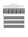
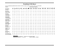
Customer Feedback Form
We would like to hear from you about the quality of the documentation, products, and service. Your
comments will help us provide increased satisfaction to our customers. Would you please take a few
minutes and complete the following questionnaire and fax it to 303-538-1741.
Please rate the effectiveness of this Implementation and Service Manual in the following areas:
1
Area
Organization
2
Clarity
3
4
5
Completeness
Accuracy
Illustrations
6
Overall satisfaction
Excellent
Good
Please provide any other comments.
Document:
Products:
Service:
Fair
Poor
Table of Contents
1
Implementation and Service Overview ................................................... 1-1
Understanding the Implementation and Service Toolset ........................................1-2
Additional Product Information Sources .................................................................1-3
Understanding the User Interface...........................................................................1-3
User Interface Procedures...............................................................................1-3
Keyboard Conventions ..................................................................................1-3
Mouse Conventions ......................................................................................1-4
OS/2 Desktop Overview ..................................................................................1-4
OS/2 Windows ..............................................................................................1-4
Graphical Objects .........................................................................................1-6
Most Commonly Performed OS/2 Tasks..........................................................1-6
To open an OS/2 window: .............................................................................1-6
2
Determining the Customer’s System Needs........................................... 2-1
Step 1: Complete the Feature Selection Sheet .....................................................2-2
Interpreting the Completed Feature Selection Sheet........................................2-2
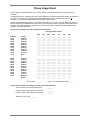
Step 2: Complete the System Sizing and Phone Usage Sheets ............................2-2
Interpreting the Completed System Sizing Sheet and Phone Usage Sheet .....2-2
Step 3: Consider Additional Hardware Needs........................................................2-5
CPU and Memory .........................................................................................2-5
Monitor .........................................................................................................2-5
Bus and Slots................................................................................................2-5
3½-inch Disk Drive........................................................................................2-5
CD-ROM Drive .............................................................................................2-5
Parallel Port ..................................................................................................2-5
Voice Boards ................................................................................................2-6
Mouse...........................................................................................................2-6
Modem .........................................................................................................2-6
UPS (Uninterruptible Power Supply) .............................................................2-6
Printer (Optional) ..........................................................................................2-6
Tape Backup (Optional) ................................................................................2-6
Brooktrout TruFax Boards (Optional) ............................................................2-6
3
Gathering Necessary Information ........................................................... 3-1
Step 1:
Step 2:
Step 3:
Step 4:
4
Complete the Preinstallation Configuration Worksheets............................3-2
Agree on a Worksheet Return Date ..........................................................3-2
Review Worksheet Information.................................................................3-3
Understand How and When to Use Worksheet Data .................................3-3
Understanding the Installation Process ................................................. 4-1
Installation Methodology Steps ..............................................................................4-2
Implementation and Service Manual
Table of Contents
i
Table of Contents
5
Preparing the Hardware........................................................................... 5-1
Assembling Materials.............................................................................................5-2
Verifying Phone System Readiness .......................................................................5-2
Confirming Dial Tone ......................................................................................5-2
Verifying the Phone System Configuration ......................................................5-2
Compiling Phone System Configuration Information........................................5-2
Configuring the Voice Boards ................................................................................5-3
Configuring DIALOG/4, D/4xD, D/42D-NS, D/42D-SX, and
D/42D-SL Boards ............................................................................................5-3
Configuring the Fax Boards ...................................................................................5-6
Configuring the Brooktrout TruFax Board ........................................................5-7
Setting the TruFax Board’s Port Address ......................................................5-7
Setting the TruFax Board’s Hardware Interrupt Level ....................................5-8
Installing the Voice and Fax Boards.......................................................................5-8
Installing Ferrite Bead Cable Clamps.....................................................................5-9
Installing the Ferrite Bead Cable Clamps on 2-Cable Boards .........................5-10
Installing the Ferrite Bead Cable Clamps on 4-Cable Boards .........................5-10
Connecting the Telephone Lines..........................................................................5-11
Connecting Dialogic DIALOG/4 and D4xD Boards.........................................5-11
Connecting the Fax Lines ....................................................................................5-11
Using the Transfer Method vs. the Non-Transfer Method...............................5-12
Connecting TruFax Boards for the Transfer Method....................................5-12
Connecting TruFax Boards for the Non-Transfer Method ............................5-13
Installing the Sentinel ..........................................................................................5-14
Installing Serial Integration Hardware...................................................................5-14
Installing and Testing the Uninterruptible Power Supply.......................................5-14
Configuring the IBM V.90 PCI Data/Fax Modem ..................................................5-15
Installing the Tape Backup Unit (Optional) ...........................................................5-17
Installing and Configuring the External Iomega Ditto Tape Drive ....................5-17
Connecting the External Ditto Tape Drive Hardware....................................5-18
Installing the Software for the External Tape Backup Drive..........................5-18
Selecting Files for Tape Backup..................................................................5-22
Setting Up the System for Automatic Backups ............................................5-23
Installing the Iomega Ditto Internal Tape Backup Drive ..................................5-25
Installing the Internal Ditto Tape Backup Drive in the PC.............................5-26
Installing the Software for the Internal Tape Backup Drive...........................5-26
Selecting Files for Tape Backup..................................................................5-29
Setting Up the System for Automatic Backups ............................................5-31
Installing a Printer (Optional) ...............................................................................5-33
6
Installing the Software ............................................................................. 6-1
Preparing the PC for System Installation ...............................................................6-2
Installing OS/2 Warp 4.0........................................................................................6-2
Installing OS/2 Warp Fix Pak 10......................................................................6-6
Implementation and Service Manual
Table of Contents
ii
Table of Contents
Installing the Messaging System Software .............................................................6-6
Verifying Files After Installation ...........................................................................6-11
Sample CONFIG.SYS File ............................................................................6-12
Sample STARTUP.CMD File.........................................................................6-12
Sample RUNVM.CMD File ............................................................................6-13
Configuring the System to Support Multiple Languages .......................................6-15
Installing Language Files...............................................................................6-15
Setting Up the System to Provide Multilingual Prompts .................................6-17
Setting Up System Mailboxes to Utilize the Multilingual Feature....................6-17
Specifying the Language for a Mailbox ..........................................................6-18
Installing and Configuring Remote Management..................................................6-18
Considerations for Using Remote Management .............................................6-18
Installing Remote Management Software Version 4.2....................................6-19
Installing and Configuring Graham Utilities ..........................................................6-23
Installing Graham Utilities..............................................................................6-23
Setting Up the System to Run HPFSDfrg Automatically During System
Maintenance..................................................................................................6-24
7
Setting Up the System to Recognize Voice and Fax Boards ................ 7-1
Specifying Dialogic Board Settings ........................................................................7-2
Specifying Settings for Dialogic DIALOG/4 and D/41D Boards ........................7-2
Specifying Settings for Dialogic D/42D-SL and D/42D-SX Boards....................7-7
Specifying Settings for the Dialogic D/42D-NS Boards ..................................7-13
Specifying Brooktrout TruFax Board Settings ......................................................7-19
8
Integrating with the Phone System ......................................................... 8-1
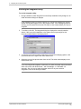
Running the Integrator Utility .................................................................................8-2
Understanding Inband Templates ..........................................................................8-5
Understanding Inband Template Characters....................................................8-5
Understanding Inband Functions .....................................................................8-6
Understanding Inband Template Rules............................................................8-7
Creating, Modifying, and Deleting Inband Templates.......................................8-8
Inband Template Examples .................................................................................8-10
9
Defining Phone System Signals.............................................................. 9-1
Determining If You Should Run Call Analysis ........................................................9-2
Meeting the Requirements to Run Call Analysis.....................................................9-2
Running the Call Analysis Utility ............................................................................9-3
Running Call Analysis in Auto Mode ................................................................9-3
Running Call Analysis in Manual Mode............................................................9-5
Re-Running the Call Analysis Utility.......................................................................9-7
Implementation and Service Manual
Table of Contents
iii
Table of Contents
10 Establishing a Serial Integration ........................................................... 10-1
Running the Serial Integration Utility After Messaging System Installation ...........10-2
Configuring the Serial Integration Utility...............................................................10-5
Supporting Multiple-Prefix Centrex Systems........................................................10-6
Creating the SMDI.TPT File ..........................................................................10-6
Example SMDI.TPT File .............................................................................10-8
Creating the SMDI.PFX Table .......................................................................10-9
Example SMDI.PFX File ...........................................................................10-11
11 Integrating with an Uninterruptible Power Supply ............................... 11-1
Understanding How UPS Integration Works.........................................................11-2
Meeting the Requirements for Running the UPS Integration Utility.......................11-2
Running the UPS Integrator Utility .......................................................................11-3
Running UPS Integration After Messaging System Installation.............................11-6
Checking the UPS’s Current Operating State Manually........................................11-9
12 Determining Outdial Strings .................................................................. 12-1
Identifying Local Area Code and Prefixes ............................................................12-2
Deleting a Prefix ..................................................................................................12-3
Activating Dial Plan .............................................................................................12-4
Understanding How Dial Plan Works ...................................................................12-5
13 Setting Up the System ........................................................................... 13-1
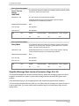
Running the System Setup Utility.........................................................................13-2
Saving the System Setup Configuration...............................................................13-2
Searching for a Particular System Setup Parameter ............................................13-3
Configuring Features and Functions on a System Level ......................................13-3
System Setup Parameters List.............................................................................13-4
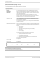
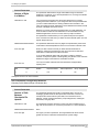
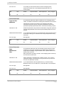
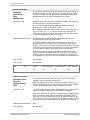
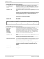
General Parameters (Page 1 of 26) ...............................................................13-8
Operator Parameters (Page 2 of 26)............................................................13-13
Invalid Mailbox Parameters (Page 3 of 26) ..................................................13-18
Time/Greetings Parameters (Page 4 of 26) .................................................13-19
Message Timing Parameters (Page 5 of 26)................................................13-21
Subscriber Parameters (Page 6 of 26).........................................................13-24
Caller Parameters (Page 7 of 26) ................................................................13-30
Networking Parameters (Page 8 of 26) ........................................................13-32
NameNet Parameters (Page 9 of 26)...........................................................13-43
Fax Parameters (Page 10 of 26)..................................................................13-44
Fax Extensions(Page 11 of 26)....................................................................13-49
Call Queuing Parameters (Page 12 of 26) ...................................................13-51
Intercom Paging Parameters (Page 13 of 26) ..............................................13-55
Call Transfer Parameters (Page 14 of 26) ...................................................13-58
Call Screening Parameters (Page 15 of 26).................................................13-65
Call Waiting Parameters (Page 16 of 26) ....................................................13-68
Implementation and Service Manual
Table of Contents
iv
Table of Contents
Outbound Dialing Parameters (Page 17 of 26) ............................................13-69
Message Delivery Parameters (Page 18 of 26)............................................13-72
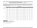
Message Indicator Parameters (Page 19 of 26) ...........................................13-74
Inband Page 1 Parameters (Page 20 of 26).................................................13-78
Inband Page 2 Parameters (Page 21 of 26).................................................13-81
Hangup Detection Parameters (Page 22 of 26)............................................13-81
Port Parameters (Page 23 of 26) .................................................................13-84
Voice System Parameters (Page 24 of 26) ..................................................13-90
Simplified Message Desk Interface Parameters (Page 25 of 26)..................13-94
Server Parameters (Page 26 of 26) .............................................................13-96
14 Setting Up System Prompts .................................................................. 14-1
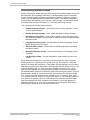
Understanding System Prompts...........................................................................14-2
Setting Up System Greetings...............................................................................14-3
Setting Up Greeting by Port .................................................................................14-5
Setting Up the Language Selection Prompt..........................................................14-7
Setting Up the Attendant Menu Prompt................................................................14-9
Setting Up Holiday Greeting Prompts ................................................................14-12
Setting Up Call Queuing Prompts ......................................................................14-13
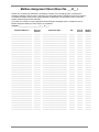
Setting Up Message Notification Prompts ..........................................................14-14
Setting Up Network Node Prompts.....................................................................14-15
15 Recording and Editing Prompts............................................................ 15-1
Selecting a Recording and Editing Technique......................................................15-2
Recording and Editing Prompts Using the Keypad Prompt Recording
Functions.............................................................................................................15-2
Recording and Editing Prompts Using SOLVE .....................................................15-3
Recording and Editing Prompts Using V-Edit .......................................................15-5
Starting V-Edit ...............................................................................................15-5
Changing the V-Edit Display..........................................................................15-7
Opening Phrase Files ....................................................................................15-8
Selecting Individual Phrases in the Phrase File .............................................15-9
Recording Phrases ......................................................................................15-10
Adding Segments to Phrases.......................................................................15-12
Removing Parts of a Phrase........................................................................15-14
Controlling Silence Before and After a Phrase.............................................15-15
Managing Phrase Files................................................................................15-15
Creating, Displaying, and Printing Text Comments......................................15-17
Shutting Down V-Edit ..................................................................................15-20
16 Managing System Mailboxes................................................................. 16-1
Creating Mailboxes..............................................................................................16-2
Things to Consider Before Creating Mailboxes ..............................................16-2
Creating a Single Mailbox..............................................................................16-3
Implementation and Service Manual
Table of Contents
v
Table of Contents
Creating a Single Duplicate Mailbox ..............................................................16-6
Creating Multiple Mailboxes ..........................................................................16-8
Creating Multiple Duplicate Mailboxes.........................................................16-11
Creating a Guest Mailbox ............................................................................16-15
Viewing and Editing a Mailbox’s Settings ...........................................................16-16
Deleting Mailboxes ............................................................................................16-17
Clearing Mailbox Information .............................................................................16-18
Searching for a Mailbox .....................................................................................16-20
Auto-Forwarding Messages to Mailboxes...........................................................16-21
Auto-Forwarding Messages Between Mailboxes on the Same System.........16-21
Auto-Forwarding Messages Between Mailboxes on Different Systems.........16-23
Notifying Subscribers of New Messages ............................................................16-24
Message Notification Sample Scenarios......................................................16-27
Managing Subscriber Settings ...........................................................................16-29
Unlocking a Mailbox ..........................................................................................16-33
Class of Service Options ...................................................................................16-34
Call Screening ..........................................................................................16-35
Message Confirmation ..............................................................................16-35
Folders .....................................................................................................16-35
Call Queuing.............................................................................................16-35
Message Indicator.....................................................................................16-36
Intercom Paging........................................................................................16-36
Personal Group List ..................................................................................16-36
Global Group List......................................................................................16-37
Dial by Name ............................................................................................16-37
Call Handling ............................................................................................16-37
V-Tree ......................................................................................................16-38
Fax V-Tree ...............................................................................................16-38
Send Messages ........................................................................................16-38
Receive Messages....................................................................................16-38
Save Messages ........................................................................................16-38
Undelete Messages...................................................................................16-38
Locate Messages Received ......................................................................16-39
Locate Messages Sent ..............................................................................16-39
Record Prompts........................................................................................16-39
Operator Access .......................................................................................16-39
Failed Login Notification ...........................................................................16-39
Mailbox Lock-Out Option ..........................................................................16-39
Auto Time-Date Voiceback .......................................................................16-40
Visual Mailbox ..........................................................................................16-40
Enable Multilingual Support ......................................................................16-40
Supervisor ................................................................................................16-40
Delivery Options .......................................................................................16-41
Not Allowed ..............................................................................................16-41
Implementation and Service Manual
Table of Contents
vi
Table of Contents
Local Only ................................................................................................16-41
Long Distance...........................................................................................16-41
Batch Mode ..............................................................................................16-41
Networking Options...................................................................................16-41
Highest Outgoing Dispatch........................................................................16-42
Casual AMIS.............................................................................................16-42
Administered AMIS ...................................................................................16-42
OctelNet ...................................................................................................16-42
Follow-Me-Forward ...................................................................................16-43
Network Reply ..........................................................................................16-43
Language..................................................................................................16-43
Fax Options ..............................................................................................16-43
Send Faxes ..............................................................................................16-43
Receive Faxes..........................................................................................16-44
Max Messages..........................................................................................16-44
Msg Time..................................................................................................16-44
Max Rings.................................................................................................16-44
New Messages..........................................................................................16-45
Saved Messages ......................................................................................16-45
Using Dialing Codes ..........................................................................................16-45
17 Working with V-Trees............................................................................. 17-1
Understanding V-Trees........................................................................................17-2
Creating V-Trees .................................................................................................17-3
Creating a Mailbox V-Tree Using Visual Architect..........................................17-4
Creating a V-Tree File from a Mailbox V-Tree ...............................................17-7
Creating a V-Tree File with the Toolkit.........................................................17-12
Creating a V-Tree Using Visual V-Tree........................................................17-16
Creating V-Trees Through the Phone Interface............................................17-18
Defining V-Tree Actions.....................................................................................17-18
V-Tree Action Summary Table ....................................................................17-19
Advance to Next Menu ................................................................................17-19
Return to Previous Menu.............................................................................17-21
Record to Mailbox and Return to Previous Level .........................................17-22
Record to Mailbox and Advance..................................................................17-23
Require Password to Proceed to Next Level ................................................17-25
Review/Edit Message and Advance.............................................................17-27
Send a Requested Fax and Advance...........................................................17-29
Send a Predefined Fax and Advance ..........................................................17-31
Disconnect ..................................................................................................17-33
Go to Mailbox Login Point ...........................................................................17-34
Go to Voice Mail..........................................................................................17-34
Go to Extension Entry Point (Automated Attendant) ....................................17-35
Go to Directory Services .............................................................................17-35
Implementation and Service Manual
Table of Contents
vii
Table of Contents
Transfer to a Mailbox...................................................................................17-36
Assigning Prompts to V-Trees............................................................................17-37
Assigning an Existing Prompt to an Option on a V-Tree...............................17-37
Recording a New Prompt for an Option on a V-Tree....................................17-37
Activating and Deactivating the Call Handling for V-Trees .................................17-39
Activating a V-Tree for a Mailbox ................................................................17-39
Deactivating a V-Tree for a Mailbox ............................................................17-41
Opening a V-Tree ..............................................................................................17-42
Opening a Mailbox V-Tree...........................................................................17-43
Copying a V-Tree File to a Mailbox .............................................................17-43
Opening a V-Tree File from Outside a Mailbox............................................17-45
Saving a V-Tree ................................................................................................17-46
Saving a Mailbox V-Tree to a V-Tree File....................................................17-46
Saving a V-Tree File ...................................................................................17-48
Saving a V-Tree File to Another File............................................................17-48
Editing a V-Tree ................................................................................................17-50
Editing V-Tree Action Information................................................................17-51
Cutting a V-Tree Menu Option to the Clipboard ...........................................17-51
Copying a V-Tree Menu Option to the Clipboard..........................................17-52
Pasting a V-Tree Menu Option from the Clipboard ......................................17-52
Deleting a V-Tree Option.............................................................................17-52
Deleting a V-Tree ..............................................................................................17-53
Deleting a V-Tree from a Mailbox ................................................................17-53
Deleting a V-Tree File .................................................................................17-54
Printing a V-Tree ...............................................................................................17-55
Changing the V-Tree Display .............................................................................17-55
Setting V-Tree Display Options....................................................................17-56
Changing the V-Tree Magnification .............................................................17-57
Hiding and Displaying Blank V-Tree Options ...............................................17-57
Expanding and Collapsing V-Tree Menus ....................................................17-57
Managing Fax Retrieval Documents ..................................................................17-58
Adding Fax Retrieval Documents ................................................................17-59
Changing the Number of a Fax Retrieval Document....................................17-60
Updating a Fax Retrieval Document ............................................................17-61
Setting Up a Cover Page for Faxes .............................................................17-62
Deleting Fax Retrieval Documents ..............................................................17-63
18 Using Network Messaging ..................................................................... 18-1
Sending Messages to Other Voice Mail Systems .................................................18-2
Receiving Messages from Other Messaging Systems..........................................18-3
Creating a Network Node.....................................................................................18-3
Creating Multiple OctelNet Nodes for Another System.................................18-11
Editing a Node...................................................................................................18-12
Deleting a Node.................................................................................................18-13
Implementation and Service Manual
Table of Contents
viii
Table of Contents
Deactivating a Node ..........................................................................................18-13
Activating a Node ..............................................................................................18-15
Searching for a Node.........................................................................................18-16
Managing NameNet Directories .........................................................................18-16
19 Installing and Configuring Visual Mailbox ............................................ 19-1
Understanding the Visual Mailbox Components ...................................................19-2
Messaging System Voice Fax Server ............................................................19-2
PBX...............................................................................................................19-2
Client PC.......................................................................................................19-3
Client Software..............................................................................................19-3
Understanding Visual Mailbox Requirements.................................................19-3
LAN...............................................................................................................19-3
LAN Server ...................................................................................................19-3
Messaging System/Voice Fax Server ............................................................19-4
Hardware ....................................................................................................19-4
Software .....................................................................................................19-4
Private Branch Exchange ..............................................................................19-5
Client PC.......................................................................................................19-5
Hardware ....................................................................................................19-5
Software .....................................................................................................19-5
Additional Client Requirements for PC Audio Features ...............................19-5
Planning for Visual Mailbox Implementation ........................................................19-6
LAN Considerations ....................................................................................19-7
Messaging System Considerations..............................................................19-7
System Security Considerations..................................................................19-7
Client Software Setup Considerations .........................................................19-7
Working with the LAN Administrator to Configure the LAN...................................19-7
Installing the Network Interface Card ...................................................................19-8
Installing OS/2 Networking Support......................................................................19-9
Installing Networking Support for a Novell NetWare LAN ...............................19-9
Installing OS/2 Networking Support for Windows NT Server Using
NetBIOS/NetBUIE .......................................................................................19-11
Installing OS/2 Networking Support for Windows NT Server Using TCP/IP ..19-13
Installing the Voice Fax Server ..........................................................................19-16
Configuring the Messaging System Software .....................................................19-20
Performing Visual Mailbox Maintenance ............................................................19-21
Viewing the Voice Fax Server Log File ........................................................19-21
Shutting Down and Restarting the Voice Fax Server ...................................19-22
Visual Mailbox File System .........................................................................19-22
Voice Fax Server Files..............................................................................19-22
Client PC Files..........................................................................................19-23
Troubleshooting Visual Mailbox ...................................................................19-23
Installation Errors......................................................................................19-23
Implementation and Service Manual
Table of Contents
ix
Table of Contents
Visual Mailbox POSTROOM Errors ..........................................................19-24
Connectivity Errors ...................................................................................19-24
System Problem Errors.............................................................................19-24
Network Fault Errors .................................................................................19-25
Internal Software Errors ............................................................................19-25
Visual Fax Warning ..................................................................................19-26
Channel Status Error.................................................................................19-26
Inactive Client Polling Problems ...............................................................19-26
Insufficient Timeouts for Active Login and Message Playback ..................19-26
Installing the Client Software on the LAN Server................................................19-27
Installing Visual Mailbox on Client PCs..............................................................19-28
Subscriber PC Considerations .....................................................................19-28
Setting Up Subscriber PCs to Use Visual Mailbox .......................................19-29
Using the Client Software Installation Template...........................................19-30
Client Software Installation Template ..........................................................19-31
20 Starting, Logging Into, and Shutting Down the System ...................... 20-1
Starting the System .............................................................................................20-2
Understanding System Security ...........................................................................20-2
Logging Into the System ................................................................................20-2
Changing Passwords .....................................................................................20-3
Logging Off the System.................................................................................20-4
Shutting Down the System...................................................................................20-5
Disabling Ports and Dropping Calls......................................................................20-5
21 Generating and Interpreting Reports.................................................... 21-1
Printing, Saving, and Displaying Reports .............................................................21-2
Printing a Report ...........................................................................................21-2
Saving a Report to Disk.................................................................................21-2
Displaying a Report Onscreen .......................................................................21-3
Mailbox Quick List Report....................................................................................21-3
Generating the Mailbox Quick List Report .....................................................21-4
Interpreting the Mailbox Quick List Report .....................................................21-4
Mailbox Usage Report .........................................................................................21-5
Generating the Mailbox Usage Report ...........................................................21-5
Interpreting the Mailbox Usage Report...........................................................21-6
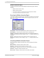
Mailbox Information Report..................................................................................21-6
Generating the Mailbox Information Report ...................................................21-7
Interpreting the Mailbox Information Report...................................................21-7
Login Failure Report ............................................................................................21-9
Generating the Login Failure Report..............................................................21-9
Interpreting the Login Failure Report ...........................................................21-10
Uninitialized Mailboxes Report...........................................................................21-11
Generating the Uninitialized Mailboxes Report ............................................21-11
Implementation and Service Manual
Table of Contents
x
Table of Contents
Interpreting the Uninitialized Mailboxes Report ............................................21-11
Port Assignments Report ...................................................................................21-12
Generating the Port Assignments Report.....................................................21-12
Interpreting the Port Assignments Report ....................................................21-12
Class of Service Report .....................................................................................21-13
Generating the Class of Service Report.......................................................21-13
Interpreting the Class of Service Report ......................................................21-13
Prompt Assignments Report ..............................................................................21-15
Generating the Prompt Assignments Report ................................................21-15
Interpreting the Prompt Assignments Report ...............................................21-15
Network Statistics Report...................................................................................21-16
Generating the Network Statistics Report ....................................................21-16
Interpreting the Network Statistics Report ....................................................21-17
22 Displaying System Statistics ................................................................. 22-1
Channel Status Window.......................................................................................22-2
Displaying the Channel Status Window .........................................................22-2
Interpreting the Channel Status Window........................................................22-2
Mailbox Status Screen.........................................................................................22-2
Displaying the Mailbox Status Screen............................................................22-2
Interpreting the Mailbox Status Screen ..........................................................22-3
Calls per Hour Screen..........................................................................................22-4
Displaying the Calls per Hour Screen ............................................................22-4
Interpreting the Calls per Hour Screen...........................................................22-4
System Usage Screen .........................................................................................22-4
Displaying the System Usage Screen ............................................................22-4
Interpreting the System Usage Screen ..........................................................22-5
50% Contention Screen .......................................................................................22-5
Displaying the 50% Contention Screen..........................................................22-5
Interpreting the 50% Contention Screen ........................................................22-6
100% Contention Screen .....................................................................................22-6
Displaying the 100% Contention Screen ........................................................22-6
Interpreting the 100% Contention Screen ......................................................22-7
System Status Dialog Box ...................................................................................22-7
Displaying the System Status Dialog Box ......................................................22-7
Interpreting the System Status Dialog Box.....................................................22-7
23 Maintaining the System.......................................................................... 23-1
Performing System File Maintenance ..................................................................23-2
Using Quick Assist to Back Up System Files .................................................23-2
Using Quick Assist to Restore System Files ..................................................23-4
Using Quick Assist to Recover System Files .................................................23-5
Verifying File Integrity .................................................................................23-5
Running a Partial Mailbox Update...............................................................23-7
Implementation and Service Manual
Table of Contents
xi
Table of Contents
Running an Update on All Mailboxes.........................................................23-10
Rebuilding All Mailboxes...........................................................................23-12
Running Quick Assist as Part of Routine System Maintenance....................23-15
Running the Lister Utility....................................................................................23-18
Adding Modules and Ports to a System..............................................................23-19
Verifying File Version Information......................................................................23-20
Refreshing Message Indicators..........................................................................23-21
Protecting Your System .....................................................................................23-22
Security Checklist........................................................................................23-28
24 Testing and Troubleshooting the System ............................................ 24-1
Testing and Troubleshooting the System .............................................................24-2
Understanding Prompts Voiced Under Specific Call Handling Conditions.............24-2
Installation Test Plan ...........................................................................................24-2
Part 1—Integration, Greeting, and Messaging Testing ...................................24-3
Part 2—Special Feature Testing..................................................................24-12
System Troubleshooting Table ..........................................................................24-19
Determining a Switch’s Disconnect Signal .........................................................24-47
Displaying Features Enabled on the Sentinel .....................................................24-47
Interpreting the View Sentinel Information ...................................................24-47
Viewing the PLUS.LOG File...............................................................................24-48
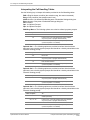
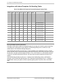
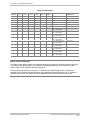
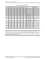
Prompts Voiced Under Specific Call Handling Conditions ..................................24-49
Interpreting the Call Handling Tables...........................................................24-50
Supervised Call Handling Table ..................................................................24-51
Integrations with Inband Templates Call Handling Tables ............................24-52
Go to Voice Mail (Call Forward to Personal Greeting) Function Table .......24-52
Busy Function Table .................................................................................24-53
Ring No Answer Function Table................................................................24-54
Customer Needs Worksheets............................................................................1
Feature Selection Sheet .................................................................................... CN-1
Feature and Functionality Introduction ............................................................... CN-3
System Sizing Sheet ........................................................................................CN-13
Phone Usage Sheet..........................................................................................CN-15
Preinstallation Configuration Worksheets .......................................................1
Company Profile Sheet........................................................................................ PI-1
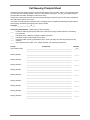
Call Flow Sheet ................................................................................................... PI-3
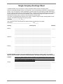
Single-Company Greetings Sheet........................................................................ PI-5
Multiple-Company Greetings Sheet ..................................................................... PI-7
Attendant Menu Prompt Sheet............................................................................. PI-9
Call Queuing Prompts Sheet ............................................................................. PI-11
Holiday Greetings Sheet .................................................................................... PI-13
Class of Service Sheet ...................................................................................... PI-15
Implementation and Service Manual
Table of Contents
xii
Table of Contents
Class of Service Information Sheet.................................................................... PI-17
Predefined COS Sheet ...................................................................................... PI-25
COS Redefinition Sheet..................................................................................... PI-27
Custom COS Definition Sheet ........................................................................... PI-29
Mailbox Assignment Sheet ................................................................................ PI-31
Auto Forward Sheet ........................................................................................... PI-33
Message Notification Sheet ............................................................................... PI-35
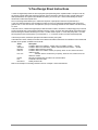
V-Tree Design Instructions................................................................................. PI-37
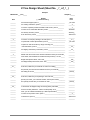
V-Tree Design Sheet ......................................................................................... PI-39
V-Tree Design Sheet Example........................................................................... PI-41
Site Information Worksheets.............................................................................1
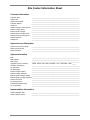
Site Contact Information Sheet ............................................................................ SI-1
System Configuration Record Setup Parameters ................................................. SI-3
Visual Mailbox Configuration Worksheets .......................................................1
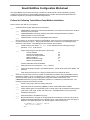
Visual Mailbox Implementation Configuration Worksheet .................................. VM-1
Novell NetWare Configuration Worksheet ......................................................... VM-3
Windows NT Configuration Worksheet .............................................................. VM-5
Glossary .........................................................................................................G-1
Index ............................................................................................................... IX-I
Implementation and Service Manual
Table of Contents
xiii
Table of Contents
Notes:
Implementation and Service Manual
Table of Contents
xiv
C H A P T E R
1
Implementation and Service Overview
The Implementation and Service Manual is designed to walk you through the steps for
®
selecting, installing, testing, and troubleshooting an Octel 100 messaging system.
Collectively, the steps presented in this manual will allow you to effectively implement
different types and sizes of systems and minimize the time spent supporting and
maintaining those systems.
This manual provides information on using all available system features and options.
Note, however, that all features and options are not available with all systems. Access to
features and options on a specific system depends on the system configuration and the
options purchased for use with the system.
Information on configuring a system with more than 16 ports is only supported for
existing systems in which more than 16 ports are already installed.
Implementation and Service Manual
1-1
1. Implementation and Service Overview
Understanding the Implementation and Service Toolset
Several organizational tools are provided in this manual to help you collect and maintain
customer, software, and site information throughout the implementation process. These
tools include:
•
Worksheets Tab – Many of the chapters in this manual include steps that
reference specific worksheets provided behind the Worksheets tab. Several of
these worksheets are designed to be completed by the system manager at the
customer’s site. (The system manager is the customer representative who will be
responsible for maintaining the messaging system after it is installed.) Other
worksheets are designed to assist you during the installation and system testing
processes. Detailed instructions on completing or obtaining information using
these worksheets, as well as interpreting and using the information, are provided
at the implementation process points where the worksheets play a part. A
summary of the purpose of each worksheet is provided below.
One copy of each worksheet is provided later in this manual. Another blank copy
of each worksheet is also included with each messaging system.
−
Customer Needs Worksheets – Help introduce the customer to messaging
system features and functionality and assists the representative with
identifying the hardware and software necessary to build the type of auto
attendant and voice/fax mail system best suited for the customer.
−
Preinstallation Configuration Worksheets – Help determine which
features should be activated on the messaging system during installation
and which, if any, can be set up before installation.
−
System Configuration Record – Provides the installer with a written
transcript of how system setup screens are completed during the installation
process and provides the installer with customer information that can be
retained for future reference.
−
Visual Mailbox™ Configuration Worksheets – Help the installer
successfully complete Visual Mailbox installation and configuration.
•
Customer Information Tab – The Customer Information tab is provided to help
you organize and retain data you collect from customer sites during the
implementation process. After you have completed the entire messaging system
implementation process, you will be prompted to store all the worksheets you
used throughout the process, along with any notes you accumulated, behind this
tab. By storing information in this way, you will have easy access to critical site
contact names and phone numbers, system setup records, and other information
you may need to reference later to provide customer assistance.
•
Additional Information Tab – The Additional Information tab is provided to help
you store additional information you may receive from time to time. This
information may include release notes, Implementation and Service Manual
updates, product alerts, or product marketing material.
Implementation and Service Manual
Implementation and Service Overview
1-2
1. Implementation and Service Overview
Additional Product Information Sources
In addition to this manual, other information tools are available:
•
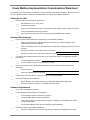
Configuration Notes – Each supported switch has an associated Configuration
Note that provides comprehensive, switch-specific integration considerations.
Configuration Notes are available through your authorized representative.
•
System Manager Manual – The system manager is the individual at the
customer site who will be responsible for maintaining the installed messaging
system. The System Manager Manual is designed to be left with a system
manager at the site. The book provides information on creating, modifying, and
deleting mailboxes; setting and modifying automated attendant features;
generating system reports; and using various other system features such as
AMIS Interface Module (AIM™), V-Trees™, and Fax Retrieval™.
•
Quick Reference Guide – An easy-to-reference, foldout card, the Quick
Reference Guide shows messaging system subscribers the telephone keypress
navigation paths to accessing messaging features. Fifty Quick Reference Guides
are provided with each messaging system shipped.
•
Wallet Card – The size of a typical business card, Wallet Cards can be easily
carried by subscribers at all times, providing them fast access to high-level
system navigation information. Fifty Wallet Cards are provided with each
messaging system shipped.
•
Online Help – Extensive online help is available on most messaging system
utilities and screens, including Visual Mailbox screens, to assist installers, system
managers, and subscribers with using the messaging system. You can access
online help using options on the Help drop-down menu and, in many cases, by
pressing <F1> from program screens.
•
Technical Support – Technical support representatives are available to assist
you with problems and issues you cannot resolve using the other available
information sources.
Understanding the User Interface
®
The Octel 100 user interface provides fast, convenient access to all of the system’s
features. This section provides an overview of the system’s graphical user interface
(GUI) and some of the most commonly used OS/2 functions.
User Interface Procedures
You can navigate the messaging system and perform operations using either the
keyboard or the mouse. Both are required to access full functionality of the messaging
system.
Keyboard Conventions
The keys listed below allow you to move around in and select items on the messaging
system screens. These keys are shown in angle brackets (< >) throughout this manual.
Keys shown within the same set of brackets but separated by the plus sign (+) constitute
key sequences, sometimes called quick keys. For example, <ALT+T> instructs you to
hold down the <ALT> key while pressing the <T> key. Several quick key combinations
are found on the messaging system pull-down menus.
Implementation and Service Manual
Implementation and Service Overview
1-3
1. Implementation and Service Overview
The key combinations and key sequences appear in the following format:
<TAB>
Moves control to the next item (field, button, etc.)
<SHIFT+TAB>
Moves control to the previous field or button.
<ALT+LETTER>
Moves control to a particular field, button, or menu choice on the
screen. Letter represents the character (usually the first) that is
highlighted in the name.
<ENTER>
Accepts input for a field or screen or selects the highlighted button.
<ESC>
Returns control to a previous screen or menu.
<SPACEBAR>
Activates and deactivates options.
Numbers shown within angle brackets (<#>) represent telephone keypad numbers.
Mouse Conventions
The following terms are used throughout this manual to describe mouse actions:
•
Point: Position the mouse pointer over a desired item.
•
Click: Press and release a mouse button.
•
Double-Click: Press and release the left mouse button twice in quick succession.
•
Select: Point to an item and click the left mouse button.
•
Open: Point to an item and double-click the left mouse button.
•
Drag: Move a selected object while holding down the right mouse button.
•
Drop: Release the right mouse button after dragging a selected object.
The instructions in the remainder of this manual are written for use of the mouse. If you
intend to use the keyboard extensively, refer back to this section for the necessary key
combinations and sequences.
OS/2 Desktop Overview
The display that appears when your computer restarts from OS/2 is called the desktop,
which is the graphical user interface of OS/2. The icons displayed on the desktop are
called objects, which may be folders, programs, or files.
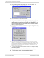
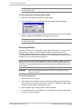
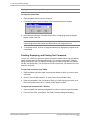
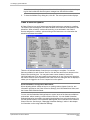
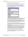
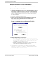
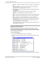
OS/2 Windows
A window is a graphical area with visible boundaries that displays information. Many
windows can be stacked on the workspace, but only one window may be active at a time.
The active window has a highlighted frame and always appears in the foreground. You
may view a list of all of the windows open at any time by pressing <CTRL+ESC> on a
blank area of the desktop to open the Window List.
Implementation and Service Manual
Implementation and Service Overview
1-4
1. Implementation and Service Overview
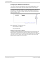
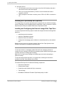
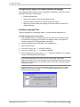
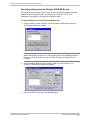
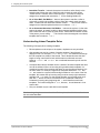
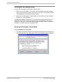
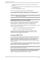
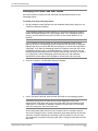
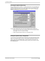
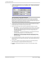
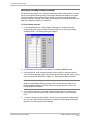
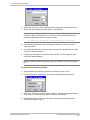
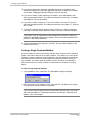
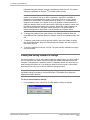
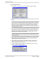
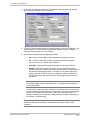
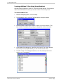
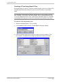
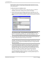
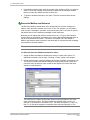
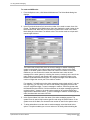
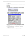
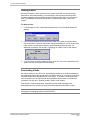
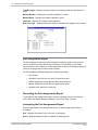
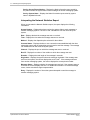
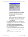
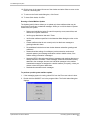
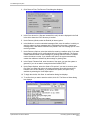
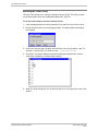
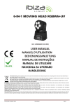
The Octel 100 System Manager is an example of an OS/2 window.
Title bar icon
Maxmize button
Maximize button
Title bar
Menu
Window frame
Window contents
Resize border
Scroll bar
Windows generally consist of the following components.
Window
Frame
The window frame is the area surrounding a window. A window frame
consists of a resize border, a title bar icon, and a title bar.
Resize
Border
The resize border surrounds the window contents and frame area. It can
be used to change the height or width of a window by clicking on it and
dragging with the mouse. Not all windows can be resized.
Title Bar
The title bar is the bar across the top of the window that consists of the
title bar icon, the title area, and the window control buttons.
Title Bar
Icon
The title bar icon (also called the Window menu button) is the object in the
left corner of the title bar that represents the window. Clicking on the icon
displays the Window menu contents and available actions.
Window
Contents
The window contents is the area within the borders of a window’s frame
that is controlled by the program (in this case, Octel 100).
Minimize
Button
The minimize button reduces an application to an icon. When minimized,
the application runs in the background. To minimize a window, position the
mouse pointer over the minimize button and click the left mouse button. To
restore a window to its original size, double-click the minimized icon.
Maximize
Button
The maximize button enlarges a window to its maximum size or to restores
a maximized window to its original size. To maximize a window, position
the mouse pointer over the maximize button and click the left mouse
button. To restore a window to its original size, click the maximize button
again.
Scroll Bar
A scroll bar allows you to view hidden parts of a window or a list by moving
the slider (the rectangle in the scroll bar) in the desired direction.
Menus
There are three types of menus. The menu bar, located across the top of
the window, contains the titles of the window’s pull-down menus. Pull-down
menus contain menu bar options, which display when you select the
menu’s title. Click a menu option to select it. Pop-up menus contain
parameter options. To open a pop-up menu, click the menu’s arrow button.
To select a menu option, click it or drag to it. To close the menu without
changing the selected value, drag the mouse pointer off the menu.
Implementation and Service Manual
Implementation and Service Overview
1-5
1. Implementation and Service Overview
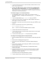
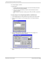
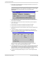
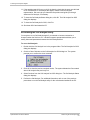
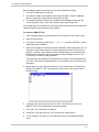
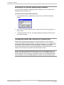
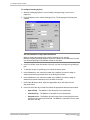
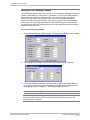
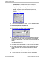
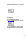
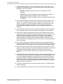
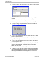
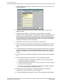
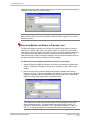
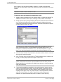
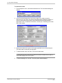
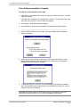
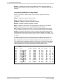
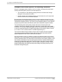
Graphical Objects
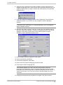
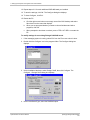
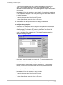
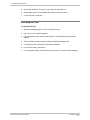
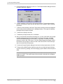
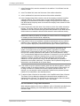
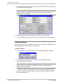
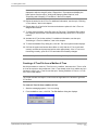
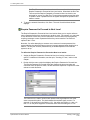
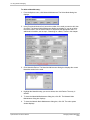
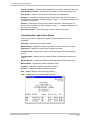
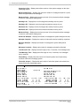
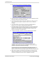
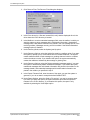
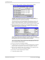
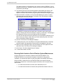
Several interactive graphical objects may appear on the messaging system windows.
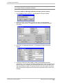
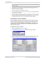
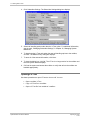
The Class of Service screen is an example of an OS/2 dialog box that contains other
graphical objects.
Dialog boxes
Dialog boxes are used to display a special message or conduct a
dialog. A dialog box may ask you to enter additional information or
confirm a decision.
Spinbox
A spinbox, which functions somewhat like a scroll bar, allows you to
incrementally change the value of an entry by clicking on the up or
down arrow buttons to the right of the field.
Push buttons
Push buttons are graphical controls that are selected (clicked on with a
mouse button) to start a designated action, such as saving your work or
opening a window. A special kind of push button is an arrow button,
which allows you to scroll through data. Arrow buttons can appear as
part of a spinbox, scroll bar, list box, or pop-up menu.
Toggle
buttons
Toggle buttons allow you to select or deselect an item by clicking on it
with the left mouse button. There are two types of toggle buttons,
checkboxes and radio buttons. Checkboxes allow you to select more
than one item from the list. Radio buttons allow you to select only one
item from a group. Selecting one item by clicking on its corresponding
radio button automatically deselects any other item.
Fields
Fields are used for text entry or edits via the keyboard. To enter text,
position the mouse cursor in the field, click in the field, and enter the
desired text. To edit an existing entry, highlight the text to be deleted
and type over it.
Most Commonly Performed OS/2 Tasks
The following tasks are those most commonly performed when using OS/2 Warp with the
messaging system:
•
Opening an OS/2 Window
•
Restarting the PC
•
Shutting the PC
Use this section as a reference until you have learned these tasks.
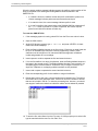
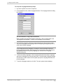
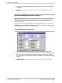
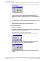
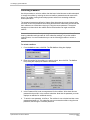
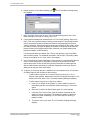
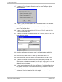
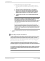
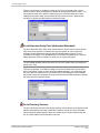
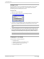
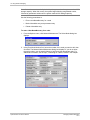
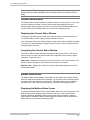
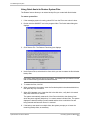
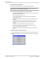
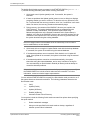
To open an OS/2 window:
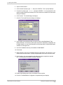
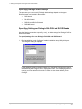
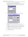
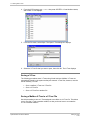
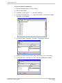
1. On the OS/2 desktop, double-click the OS/2 System icon. The OS/2 System folder
opens.
2. In the OS/2 System folder, double-click the Command Prompts icon. The Command
Prompts folder opens.
3. In the Command Prompts folder, double-click the OS/2 Window icon. An OS/2
window displays.
Implementation and Service Manual
Implementation and Service Overview
1-6
1. Implementation and Service Overview
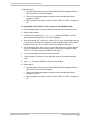
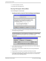
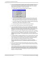
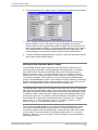
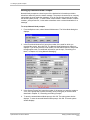
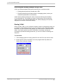
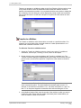
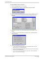
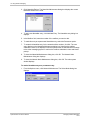
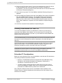
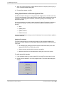
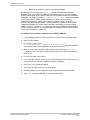
To restart OS/2:
1. Click the right mouse button on an empty area of the OS/2 desktop and select Shut
down from the menu that displays.
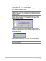
2. When you are prompted whether you want to close all windows and active programs,
click OK.
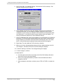
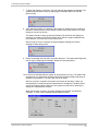
3. When prompted to shut down or reboot, press <CTRL+ALT+DEL> to restart the PC.
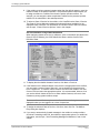
4. When the PC restarts, a Recovery Choices screen displays. This screen, which is for
support purposes, displays for 5 seconds before the system continues with the
startup.
To shut down OS/2:
1. Click the right mouse button on an empty area of the OS/2 desktop and select Shut
down from the menu that displays.
2. When you are prompted whether you want to close all windows and active programs,
click Yes.
3. When prompted to shut down or reboot, turn off power to the PC.
Implementation and Service Manual
Implementation and Service Overview
1-7
1. Implementation and Service Overview
Notes:
Implementation and Service Manual
Implementation and Service Overview
1-8
C H A P T E R
2
Determining the Customer’s System Needs
The steps provided in this chapter will help you to:
•
Introduce the messaging system to your customer
•
Understand the customer’s system needs and expectations
•
Determine the hardware and software required to support a system that meets
the customer’s needs and expectations
As you follow the steps in this chapter, you will ask the customer to complete three of the
Customer Needs worksheets provided behind the Worksheets tab in this manual:
•
Feature Selection Sheet
•
System Sizing Sheet
•
Phone Usage Sheet
Information on using the data you obtain with these worksheets to determine the
customer’s system needs is provided within each step. Note that new turnkey messaging
systems meet all of the necessary requirements.
Information on systems with more than 16 ports is only supported for existing systems in
which more than 16 ports are already installed.
Implementation and Service Manual
Determining the Customer’s System Needs
2-1
2. Determining the Customer’s System Needs
Step 1: Complete the Feature Selection Sheet
The Feature Selection Sheet provides a forum for introducing the customer to the wide
range of available features and identifying and discussing which features are most
critical to satisfying the customer’s needs. Provide the customer with both the worksheet
and the Feature and Functionality Introduction information (also included behind the
Worksheets tab). The customer will need to consult the Feature and Functionality
Introduction while completing the Feature Selection Sheet. Be sure to encourage the
customer to contact you with any questions on the material presented.
Interpreting the Completed Feature Selection Sheet
Use data provided on the Feature Selection Sheet to understand and set customer
expectations.
First, by considering the features that the customer has indicated are important, identify
which optional add-on modules should be included with the customer’s system. Optional
o
modules are identified on the Feature Selection Sheet with a superscript “o” ( )
immediately following the feature name. Optional modules will impact the price of the
system. By determining early on which of these add-on modules are necessary, you can
continually consider the pricing implications during the sales process. For pricing
information, see your sales kit.
Second, ensure that the switch the customer plans to use with the system supports the
features the customer has indicated are important. Do this by consulting the Feature
Selection Sheet in conjunction with the Configuration Note issued for the customer’s
switch. The Configuration Note identifies switch limitations and helps you to present
those limitations to the customer now, so there are no surprises later. Features that may
be unavailable with certain switches are identified on the Feature Selection Sheet with a
s
superscript “s” ( ) immediately following the feature name.
Step 2: Complete the System Sizing and Phone Usage Sheets
The System Sizing Sheet and Phone Usage Sheet help you better define the hardware
needed to support the customer’s system. Using the data provided on these sheets and
the instructions provided in the following procedure, you can determine:
•
Number of ports the system should include
•
Number of mailboxes the system will support
•
PC hard drive size required
Interpreting the Completed System Sizing Sheet and
Phone Usage Sheet
To determine the number of ports necessary and mailboxes supported:
1. For each line entered on the System Sizing Sheet, add the Direct and Indirect values
and enter the sum in the Leave Blank, for Vendor Use 1 column.
2. Multiply that sum by the Highest Number in Group value, and enter the result in the
Leave Blank, for Vendor Use 2 column.
Implementation and Service Manual
Step 1: Complete the Feature Selection Sheet
2-2
2. Determining the Customer’s System Needs
3. Add all the values in the Highest Number in Group column to determine the total.
4. Add all the values in the Leave Blank, for Vendor Use 2 column to determine the
total. Divide this number by the total Highest Number in Group figure from step 3.
This produces the Weighted Average of Minutes per Day per Mailbox value.
Refer to the Phone Usage Sheet. If phone system statistics are provided (the top section
of the form is complete), continue with step 1, below. If call estimates are provided (the
bottom section of the form is complete), continue with step 3.
1. Determine the Average Number of Calls per Business Day by dividing the sum of
each business day column by the number of business days in the week.
2. Determine the Busiest Hour Percent of Calls by dividing the Average Number of
Calls per Business Day figure by the number of calls during the busiest hour of the
week. Skip step 3, and continue with step 4.
3. Determine the Busiest Hour Percent of Calls by dividing the number of calls on an
average business day by the number of calls in the busiest hour of the busiest day of
the week.
4. Considering the Weighted Average Minutes per Day per Mailbox figure calculated on
the System Sizing Sheet and the Busiest Hour Percent of Calls figure calculated on
the Phone Usage Sheet, locate the row in the following table that best applies to the
customer. Following the row across, you can identify the number of mailboxes
supported by different port sizings. By considering the size of the customer’s
organization and other needs and expectations the customer identified on the
Feature Selection Sheet, estimate the number of ports necessary for the customer.
Port Sizing Table
Weighted
Avg.
Busiest Hour
% of Calls
4
Ports
8
Ports
12
Ports
16
Ports
20
Ports
24
Ports
28
Ports
32
Ports
10
18
50
151
265
385
508
634
762
892
“
14
65
194
340
494
653
815
980
1146
“
10
91
272
477
692
915
1141
1372
1605
8
18
65
189
331
480
635
792
953
1115
“
14
81
243
426
618
816
1019
1225
1433
“
10
114
340
596
865
1143
1427
1715
2006
6
18
84
252
442
641
847
1057
1271
1486
“
14
108
324
567
824
1089
1359
1634
1911
“
10
152
454
795
1154
1525
1903
2287
2675
4
18
127
378
662
961
1270
1585
1906
2229
“
14
163
486
851
1236
1633
2038
2450
2866
“
10
229
681
1192
1731
2287
2854
3430
4012
2
18
254
758
1325
1923
2541
3172
3812
4458
“
14
327
973
1703
2473
3268
4028
4901
5732
“
10
457
1362
2385
3462
5083
5709
6861
8025
Implementation and Service Manual
Step 2: Complete the System Sizing and Phone Usage Sheets
2-3
2. Determining the Customer’s System Needs
To determine the hard drive size required:
1. For each line entered in the System Sizing Sheet, multiply the Number in Category
value by the Average Number of Messages Stored value. Multiply the result by the
Average Length of Message value divided by 60 (to convert seconds to minutes).
Enter the result in the Leave Blank, for Vendor Use 3 column.
2. Multiply the Number in Category value by the Average Number of Faxes Stored
value. Multiply the result by the Average Number of Pages per Fax value divided by
4 (because four pages of typical fax data can be stored in one minute of storage
space). Enter the result in the Leave Blank, for Vendor Use 4 column.
3. Add the values in the Leave Blank, for Vendor Use 3 column to determine the
minutes of storage required for messages. Add the values in the Leave Blank, for
Vendor Use 4 column to determine the minutes of storage required for faxes. Add
these totals together to determine the total minutes of storage required. Multiply this
figure by 1.15 to increase it by 15%, providing a peak load adjustment.
4. To determine the minimum megabytes of hard drive space required for message
storage, multiply the Minutes of Disk Space Storage Required value by .25.
5. To determine the minimum total megabytes of hard drive space required to house
messages and the OS/2 and system software, prompts, and subscriber information
for up to 1,000 subscribers, add 100 MB to the number determined in step 4.
Example:
Category of
No. in
Subscriber
Category
Executive
5
Manager
20
General Professional
80
Service Technician
30
Order Entry Clerk
20
Other Clerks
30
Secretary
15
Avg. No.
Avg. Len.
Avg. No.
Avg. No.
of Msgs
of a Msg
of Faxes
of Pages
Vendor Use
PerFax
3
4
Stored
(Seconds)
Stored
6
45
8
10
22.5
100
6
30
5
8
60
200
4
30
5
5
200
500
5
20
4
3
70
90
2
30
2
2
50
20
2
30
2
2
45
30
3
30
3
4
15
45
Minutes of storage required for messages ---------->462.5
985
Minutes of storage required for Faxes ------------------------------ ↑
Total Minutes of Storage Required: (462.5 + 985)
15% Peak Load Adjustment: (1.15 x 1447.5)
Minutes of Disk Space Storage Required:
Minimum Megabytes Required for Messages: (1664.5 x .25)
Minimum Megabytes Required for OS/2, system software, etc.:
Minimum Total Megabytes Required:
Implementation and Service Manual
1447.5
+ 217
1664.5
416
100
516
Step 2: Complete the System Sizing and Phone Usage Sheets
2-4
2. Determining the Customer’s System Needs
Step 3: Consider Additional Hardware Needs
The hardware requirements listed below represent the minimum required to run OS/2
and the messaging system software efficiently.
CPU and Memory
Use the following table to determine the minimum system CPU and memory
requirements.
Voice
Ports
System without Visual
Mailbox
System with < 50 Visual
Mailbox Clients
System with 50 - 250 Visual
Mailbox Clients
4
486 /33 w/ 16 MB RAM
486 /33 w/ 16 MB RAM
486 /66 w/ 16 MB RAM
8
486 /33 w/ 16 MB RAM
486 /33 w/ 16 MB RAM
486 /66 w/ 16 MB RAM
12
486 /33 w/ 16 MB RAM
486 /100 w/ 16 MB RAM
486 /100 w/ 16 MB RAM
16
486 /33 w/ 16 MB RAM
486 /100 w/ 16 MB RAM
486 /100 w/ 24 MB RAM
20
486 /33 w/ 24 MB RAM
486 /100 w/ 24 MB RAM
486 /100 w/ 24 MB RAM
24
486 /33 w/ 24 MB RAM
486 /100 w/ 24 MB RAM
486 /100 w/ 24 MB RAM
28
486 /100 w/ 24 MB RAM
486 /100 w/ 32 MB RAM
P100 w/ 32 MB RAM
32
486 /100 w/ 24 MB RAM
486 /100 w/ 32 MB RAM
P100 w/ 32 MB RAM
Certain PCs have Energy Saving Modes that, when enabled, automatically shut down or
conserve energy in various parts of the PC. Areas affected can include the hard drive
(may stop spinning), the monitor (may be dimmed or turned off), and the CPU and
associated components (may be put to “sleep” in a low-power consumption mode).
These energy saving features can hinder performance and cause other system
problems. If you are running on a PC with these features, you must disable them in the
PC’s CMOS. Consult your PC manual for instructions. This feature is disabled on all
turnkey messaging systems.
Monitor
A monochrome VGA or better is recommended.
Bus and Slots
The only voice and fax boards available for use with the system require the ISA bus
interface. Each voice board requires one 8- or 16-bit slot (depending on the board), and
each TruFax board requires one full-length 16-bit slot. It is recommended that at least
one full-length 16-bit slot be available for future expansion.
3½-inch Disk Drive
One 1.4 megabyte, 3½-inch drive may be used to install software and perform system
backups.
CD-ROM Drive
A CD-ROM drive is required for software installation.
Parallel Port
A parallel port is required for the sentinel protection device and the optional printer. This
port must be bidirectional, as most are today.
Implementation and Service Manual
Step 3: Consider Additional Hardware Needs
2-5
2. Determining the Customer’s System Needs
Other than the printer or a BackPak external CD-ROM, nothing should be connected to
the same parallel port as the sentinel. The sentinel may be corrupted if a tape backup
unit is connected to it or if file transfer software is run through it. If you want to use a
tape backup unit or a file transfer program, either use a different parallel port, use a
device that connects to a serial port, or disconnect the sentinel while you are using the
other program or device (make sure the messaging system is shut down first).
Voice Boards
Dialogic voice boards are supported for the system. The system only recognizes a voice
board if the EPROM has been programmed to contain the proper “signature.” If a
nonsignatured board is detected during initialization, its ports are disabled.
Mouse
A mouse is required for full functionality of the system.
Modem
A modem can be used for remote diagnostics. Modems with a minimum speed of 9600
bps are recommended. An internal modem is supplied with the messaging system.
Contact your authorized representative for additional information.
UPS (Uninterruptible Power Supply)
A UPS protects the system PC from a sudden loss of power. You must connect the UPS
to a serial port if you plan to run UPS integration. See Chapter 11, “Integrating with an
Uninterruptible Power Supply,” for additional information.
Printer (Optional)
A printer can be attached to the messaging system PC to produce hard copies (reports,
V-Trees, for example). The printer, which must connect to a parallel port, can be
attached to the back of the system’s sentinel unit. The printer and/or PC must include
drivers that allow the printer to operate properly with OS/2 programs. For information on
required drivers, consult the printer and OS/2 documentation.
Tape Backup (Optional)
A tape backup unit can be used to archive your entire messaging system or a portion of
it (for example, phrase files). For additional information on tape backup units, contact
your authorized representative.
Brooktrout TruFax Boards (Optional)
Two-port Brooktrout TruFax boards can be installed to use the Fax Solution™ fax mail
and fax retrieval features. The system recognizes a fax board only if the EPROM has
been programmed to contain the correct “signature.” If a nonsignatured board is
detected during initialization, its ports are disabled.
Implementation and Service Manual
Step 3: Consider Additional Hardware Needs
2-6
C H A P T E R
3
Gathering Necessary Information
The steps provided in this chapter will help you to:
•
Collect information from the customer that you will use during the messaging
system installation and system setup process
•
Review the information provided with the customer, validating completeness and
accuracy
•
Understand how that information is used during the messaging system
implementation process
As you follow the steps in this chapter, you will ask the customer to complete the
Preinstallation Configuration Worksheets provided behind the Worksheets tab in this
manual.
Information on using the data you obtain on these worksheets is provided in this chapter
and throughout this manual.
Implementation and Service Manual
Gathering Necessary Information
3-1
3. Gathering Necessary Information
Step 1: Complete the Preinstallation Configuration Worksheets
There are 14 worksheets provided behind the Worksheets tab in this manual that are
collectively referred to as the Preinstallation Configuration Worksheets. These
worksheets prompt the customer to provide information that will assist you as you install
and set up the customer’s messaging system. Before you begin the installation process,
ask the customer to complete the following sheets:
•
•
•
•
•
•
•
•
•
•
•
•
•
Company Profile Sheet
Call Flow Sheet
Single-Company Greetings Sheet or Multiple-Company Greetings Sheet
Attendant Menu Prompt Sheet
Call Queuing Prompts Sheet
Holiday Greetings Sheet
Class of Service Sheet
COS Redefinition Sheet
Custom COS Definition Sheet
Mailbox Assignment Sheet
Auto Forward Sheet
Message Notification Sheet
V-Tree Design Sheet
Instructions on completing Preinstallation Configuration Worksheets are provided at the
top of each sheet. Though these instructions should be adequate, be sure to encourage
customers to contact you immediately with any questions.
To assist customers in completing certain sheets, be sure to provide them with the
following information, which is also included behind the Worksheets tab:
•
•
•
Class of Service Information Sheet
Predefined COS Sheet
V-Tree Design Sheet Instructions and V-Tree Design Sheet Example
When asking customers to complete the worksheets, inform them that Prompt # and
Mailbox # fields that display in italics on many of the sheets will be completed by the
installer when the system is implemented at the site.
Step 2: Agree on a Worksheet Return Date
In an effort to facilitate the implementation process, be sure to set a worksheet
completion target date with the customer. Contact the customer two or three days prior
to that target date to ensure that the worksheets will be completed on time and to
address any questions the customer may have.
Implementation and Service Manual
Step 1: Complete the Preinstallation Configuration Worksheets
3-2
3. Gathering Necessary Information
Step 3: Review Worksheet Information
After you receive completed Preinstallation Configuration Worksheets from the
customer, review each worksheet. Be sure to note:
•
Missing worksheets
•
Missing worksheet entries
•
Seemingly inconsistent or odd worksheet entries
•
Worksheet entries that require optional add-on modules you had not previously
planned to include with the system
By carefully reviewing the Preinstallation Configuration Worksheets your customer
provides, you can become increasingly familiar with the customer’s system needs and
expectations before you actually implement the messaging system. You can also identify
any additional optional modules that should be included with the system and were not
previously planned. Furthermore, by identifying missing or seemingly inconsistent data
now, you can immediately address worksheet entries that were confusing to or
overlooked by the customer to facilitate the actual installation and setup steps.
Step 4: Understand How and When to Use Worksheet Data
The steps provided in this manual will guide you through the messaging system
installation and setup process and periodically refer you to specific customer entries on
the Preinstallation Configuration Worksheets, so you can make informed installation and
setup decisions. In general terms, you will be asked to refer to worksheet entries while
completing the following installation and setup tasks:
•
Configuring software parameters on the System Setup screens
•
Defining the functionality of the automated attendant
•
Setting up special features for the customer, such as V-Trees or Visual Mailbox
Note that, after you complete the entire system implementation process, you should
store all the worksheets you used throughout the process, along with any notes you
accumulated, behind the Customer Information tab in this manual. By doing so, you
have easy access to critical site contact information, system setup records, and other
information that can help you better support customers.
Implementation and Service Manual
Step 3: Review Worksheet Information
3-3
3. Gathering Necessary Information
Notes:
Implementation and Service Manual
Step 4: Understand How and When to Use Worksheet Data
3-4
C H A P T E R
4
Understanding the Installation Process
This chapter provides information on the general methodology you must follow to
successfully install, set up, and test the messaging system.
An Installation Checklist is provided separately with the messaging system to guide you
through the installation methodology. Copy and use this checklist each time you perform
a messaging system installation.
In almost all cases, the messaging system is delivered with all necessary voice and fax
boards and both the OS/2 and Octel® 100 software preinstalled. Consequently, you may
not need to complete many of the hardware and software installation procedures
discussed in this manual. Information provided in each chapter instructs you whether you
should complete a specific installation procedure.
Implementation and Service Manual
Understanding the Installation Process
4-1
4. Understanding the Installation Process
Installation Methodology Steps
The following table identifies each general system installation step and its purpose.
Detailed procedures for completing each step are provided throughout this manual.
Installation Step
Purpose and Importance
Determine the customer’s
system needs and gather
necessary customer
information
By defining exactly what your customer needs from the
messaging system, you can address issues, concerns, and
questions early on, thereby facilitating communication and
avoiding confusion and surprises later. You can also make
informed decisions on the size of the system, type of hardware,
and the optional add-on modules necessary to meet your
customer’s needs. For additional information, see Chapter 2,
“Determining the Customer’s System Needs.”
Verify phone system
configuration
During the installation process, you will need to provide specific
information on the customer’s phone switch and system. This step
prompts you to gather that information prior to installation, so that
you have all the information you need at hand. This step is
particularly critical if the switch at the customer’s site is not
among those supported by the system’s Integrator utility. The
Integrator utility sets several codes and parameters to those
settings best suited for a particular switch. For additional
information on the Integrator-supported switches, contact a
technical support representative. For additional information on
using Integrator, see Chapter 5, “Preparing the Hardware.”
Assemble the required
materials
To facilitate the actual installation process, you need to assemble
all the materials you will be using. This helps to dramatically
improve your installation efficiency. A list of required materials is
included in the Installation Checklist, which is provided separately
with the messaging system.
Prepare the PC for
installation
Before you install the system on the PC, you must set up and
install certain hardware components such as the voice board and
sentinel. This step walks you through the procedures. For
additional information, see Chapter 5, “Preparing the Hardware.”
Install the OS/2 and
system software
On turnkey systems, the OS/2 and messaging system software is
preinstalled. If the software needs to be reinstalled, see Chapter 6,
“Installing the Software.”
Run the Configure utility
The Configure utility enables the system to recognize the installed
voice and fax boards. On turnkey systems, the voice boards are
preinstalled in the system PC and the Configure utility is
preconfigured. For information on running the Configure utility,
see Chapter 7, “Setting Up the System to Recognize Voice and
Fax Boards.”
Run the Integrator utility
The Integrator utility configures the system for use with the phone
switch installed at the customer site. The Integrator utility is
preconfigured on some systems. To determine if you must run the
Integrator utility, launch Integrator and verify that the Currently
Installed Switch field displays the name of the switch to which the
system will be connected. If the field displays None or if the name
displayed for the installed switch is incorrect, you must run
Integrator. For information on running the Integrator utility, see
Chapter 8, “Integrating with the Phone System.”
Run the Call Analysis
Utility
The Call Analysis utility enables the system to recognize the
specific signals of the phone system to which it is connected. For
information on whether you must run the Call Analysis utility, refer
to Chapter 9, “Defining Phone System Signals.”
Implementation and Service Manual
Installation Methodology Steps
4-2
4. Understanding the Installation Process
Installation Step
Purpose and Importance
Run the System Setup
utility
The System Setup utility configures the system. For information
on running the System Setup utility, see Chapter 13, “Setting Up
the System.”
Install the Visual Mailbox
module (optional)
The Visual Mailbox software is preinstalled on most systems.
However, there are additional steps you must perform to complete
Visual Mailbox installation. For information on implementing
Visual Mailbox, see Chapter 19, “Installing and Configuring Visual
Mailbox.”
Configure serial
integration (optional)
If the phone system at the customer site requires a serial
integration, you must install the appropriate serial integration
software and run the ICONFIG utility. For information on running
serial integration, see Chapter 10, “Establishing a Serial
Integration.”
Run the UPS utility
(optional)
It is strongly recommended that the UPS utility be run to integrate
the system and the attached UPS. Note that the UPS must have a
serial port connection to run UPS integration. The UPS shipped
with the messaging system has this connection. For information
on running the UPS utility, see Chapter 11, “Integrating with an
Uninterruptible Power Supply.”
Run the Dial Plan utility
(optional)
The Dial Plan utility determines the correct outdial string for a
number of outbound operations. For information on running the
Dial Plan utility, see Chapter 12, “Determining Outdial Strings.”
Test the system using the
provided test plan
After you have completed the actual software installation and
setup steps, it is critical that you comprehensively test the system
to ensure it is functioning properly. This step takes you through a
low-level test plan and helps you to troubleshoot any problems.
For information on testing the system, see Chapter 24, “Testing
and Troubleshooting the System.”
Document and store site
information
By completing the Site Information worksheets, provided behind
the Worksheets tab in this manual, and storing this information
with other worksheets used during the installation process, you
have an easy-to-reference snapshot of key contact personnel, site
data, and system setup information. This information can help you
more quickly resolve customer support issues, since you should
have available most if not all the information necessary to resolve
an issue.
Implementation and Service Manual
Installation Methodology Steps
4-3
4. Understanding the Installation Process
Notes:
Implementation and Service Manual
Installation Methodology Steps
4-2
C H A P T E R
5
Preparing the Hardware
In almost all cases, the messaging system is delivered with all necessary voice and fax
boards installed. Consequently, you may not need to complete certain hardware
configuration and installation steps detailed in this chapter. You should, however,
connect the phone and fax lines to the messaging system and install certain additional
hardware components, such as the uninterruptible power supply (UPS). If you need to
install new hardware in the messaging system PC or you need to modify the hardware,
this chapter will provide detailed board setup and installation information. The steps
provided help you to:
•
Assemble the necessary materials
•
Verify phone system readiness
•
Configure the voice boards
•
Configure the fax boards
•
Install the voice and fax boards in the PC
•
Connect the phone and fax lines to the phone system
•
Install the sentinel on the PC
•
Install the Serial integration device in the PC
•
Install and test the UPS
•
Install and configure the modem
•
Install the tape backup unit (optional)
•
Install printer (optional)
As you follow the steps in this chapter, complete the appropriate section of the
Installation Checklist.
Implementation and Service Manual
Preparing the Hardware
5-1
5. Preparing the Hardware
Assembling Materials
Before you begin hardware installation, assemble the materials you are required to use.
The materials are listed on the Installation Checklist provided with the messaging
system.
Some of the equipment listed, such as a tape backup device, is optional and therefore
not required for the messaging system.
Verifying Phone System Readiness
Before beginning hardware installation, you must make sure that the phone system is
ready for system installation by:
•
Confirming the presence of a dial tone on each board used
•
Verifying that the phone system is configured properly
•
Compiling phone system configuration information
Confirming Dial Tone
The first step in preparing the phone system at the customer site is to establish the
presence of dial tone.
To confirm the presence of a dial tone on the phone system:
1. Connect one end of a modular plug into the phone system.
2. Plug the other end of the modular plug into a 2500 set, a telephone test set, or the
proprietary telephone instrument if using a Dialogic D/42D-NS, D/42D-SX, or
D/42D-SL integration.
3. Lift the handset and confirm that a dial tone is present.
Verifying the Phone System Configuration
Verify that the phone system is configured properly for the system:
•
Ensure that the phone system technician followed the procedures detailed in the
latest Configuration Note when programming the phone system.
•
If a Configuration Note is not available for the customer’s switch, contact a
technical support representative for information on the codes required.
Compiling Phone System Configuration Information
Obtain the following phone system configuration information:
•
List of hunt groups configured for the phone system, if there are any.
•
List of active phone system features, such as a distinctive ring or auto answer,
so you can ensure they do not conflict with the intended application.
Implementation and Service Manual
Assembling Materials
5-2
5. Preparing the Hardware
Configuring the Voice Boards
Voice boards provide the interface between the messaging system and the phone
system that allows them to communicate. You must configure the jumpers and switch
settings on the Dialogic voice boards before you install them. Note that after you install
the messaging system, you must also configure the software to recognize the voice
boards.
Voice boards contain ports, which are the interface between a voice board and a phone
system channel.
The boards you install in the PC must be purchased from your messaging system
provider so they are programmed with the proper signature. If a nonsignatured board is
detected during system initialization, the number of ports on that board is not available.
In addition, the system writes an entry to the log file identifying the location of the
nonsignatured board.
WARNING:
Use caution when handling voice boards as they are
electrostatic-sensitive. Be sure you ground the PC, the work area, and
the ground end of the antistatic wrist strap prior to handling a board, and
always use antistatic wrist straps and/or electrostatic-dissipative mats
while handling a board.
The following Dialogic boards are supported:
•
DIALOG/4: 4-port, half-length board
•
D4xD: 4-port board
•
D/42D-NS: 4-port digital board
•
D/42D-SL: 4-port digital board
•
D/42D-SX: 4-port digital board
In the voice board drawings, the black square in the switch settings indicates the jumper
position.
Configuring DIALOG/4, D/4xD, D/42D-NS, D/42D-SX, and
D/42D-SL Boards
The steps for configuring the DIALOG/4, D/4xD, D/42D-NS, D/42D-SX, and D/42D-SL
boards are identical.
Different versions of the Dialogic voice boards may be installed in existing messaging
systems; therefore, the location of the relevant jumpers and switches may vary between
versions. Note that only the jumper blocks and switches relevant to the boards’
configuration for the messaging system are depicted in the diagrams, and that individual
switches may not be labeled on the actual boards.
Implementation and Service Manual
Configuring the Voice Boards
5-3
5. Preparing the Hardware
The following diagram illustrates the DIALOG/4 board.
The following diagram illustrates the D/4xD board. The location of the relevant jumpers
and switches on the D/42D-SX and D/42D-SL boards are approximately the same as on
the D/4xD board.
The following diagram illustrates the D/42D-NS board.
Complete the following steps, as required, to configure each Dialogic board:
1. Set the board’s base shared memory address.
2. Modify the board’s base memory segment.
3. Set the board’s hardware interrupt.
4. Set the default line state.
5. Configure for multiple boards.
Implementation and Service Manual
Configuring the Voice Boards
5-4
5. Preparing the Hardware
Setting the board’s base shared memory address – The base shared memory
address allows the voice board to communicate with the voice driver and, in turn, the
messaging system. SW1 determines the Dialogic board’s base shared memory address.
If you are only installing one Dialogic board, leave SW1 at the default setting unless it
conflicts with another component. If you are installing multiple boards or if there is a
conflict, you can change the base shared memory address by configuring the first three
switches on SW1.
The following figure illustrates the recommended switch settings. The first column lists
the board number, the second column lists the base shared memory address that should
be assigned to each board, and the third column represents the switch settings that
correspond to the base shared memory address.
Record the Shared Memory Address for each DIALOG/4, D/4xD, D/42D-NS, D/42D-SX,
and D/42D-SL board you configure. You will need to enter this information when you run
the Configure utility.
Modifying the board’s base memory segment – The shared memory block on the PC
is called a segment. Most Dialogic boards use the D segment, which is the default. To
use the D segment, make sure that the J5 and J6 jumper clips are removed.
If you cannot use the D segment due to a conflict or for some other reason, a technical
support representative can advise you to use an address in segment A or C.
To use an alternate segment, you must install one of two jumpers on the Dialogic board:
•
Install the JP5 jumper clip if you assign the voice board an address using the A
segment, such as A0000.
•
Install the JP6 jumper clip if you assign the voice board an address using the C
segment, such as C0000.
Implementation and Service Manual
Configuring the Voice Boards
5-5
5. Preparing the Hardware
Do not change the settings of either of these jumpers unless a technical support
representative directs you to set the voice board to an address using an alternate
segment.
Setting the board’s hardware interrupt – The JP1 jumper block sets the Dialogic
board hardware interrupt level, also called the IRQ. Interrupt settings for these boards
range from 2 through 7. Install the jumper that corresponds to the interrupt level you
want to use. You must set all Dialogic boards to the same interrupt level. The
recommended interrupt is IRQ 5. Depending on the system configuration, you may have
to try different interrupts before you find one that does not conflict with other devices.
Record the Hardware Interrupt for each DIALOG/4, D/4xD, D/42D-NS, D/42D-SX, and
D/42D-SL board you configure. You will need to enter this information when you run the
Configure utility.
Setting the board’s default line state – The fourth switch on SW1 determines whether
the lines connected to the voice board return a ring-no-answer signal or a busy signal
when the messaging system is not running. Make sure this switch is always on, as shown
in the board diagrams, to indicate that the lines should return a busy signal when the
messaging is not running.
Configuring for multiple boards – If you are using a single voice board, leave the JP7
jumper clip installed. If you are installing multiple Dialogic boards, leave the JP7 jumper
clip on the first Dialogic voice board (which has the lowest base shared memory address)
and remove the JP7 jumper clip on the other Dialogic boards.
Configuring the Fax Boards
Fax boards allow the messaging system to use the Fax Solution features. You must
configure the jumpers and switch settings on the Brooktrout fax boards before you install
them. The Brooktrout TruFax fax board is supported.
Fax boards contain ports, which are the interface between the fax board and a phone
system channel.
The boards you install in the PC must be purchased from your messaging system
provider so they are programmed with the proper signature.
Brooktrout TR112 and TR114 boards are supported in existing systems in which they are
already installed. Contact a technical support representative if you have one of these
boards and need installation or configuration information.
Implementation and Service Manual
Configuring the Fax Boards
5-6
5. Preparing the Hardware
Configuring the Brooktrout TruFax Board
The TruFax is a 2-port fax board supported for use with the messaging system. In the
board drawing, the black square in the switch settings indicates the jumper position.
Use caution when handling fax boards as they are electrostatic-sensitive. Make sure you
ground the PC, the work area, and the ground end of the antistatic wrist strap prior to
handling a board, and always use antistatic wrist straps and/or electrostatic-dissipative
mats while handling a board.
Before installing the TruFax board, you must:
•
Set the board’s port address
•
Set the interrupt level
Setting the TruFax Board’s Port Address
The board’s port address allows the PC and the Brooktrout board to communicate. The
Address Selector switch determines the board’s port address. Use the default setting,
140, for the first TruFax board. If you are using multiple TruFax boards, you must assign
each board a unique port address. The following figure illustrates the recommended
Address Selector settings for each TruFax board.
Implementation and Service Manual
Configuring the Fax Boards
5-7
5. Preparing the Hardware
The system searches addresses 140 through 280 to determine if fax boards are present.
Because the system considers any board found in this range of addresses a fax board,
do not set other boards, such as a network interface card (NIC), to addresses within this
range.
Record the port address for each TruFax board you configure; you will need to refer to it
when you run the Configure utility.
Setting the TruFax Board’s Hardware Interrupt Level
The interrupt jumper in the upper-left corner of the board controls the TruFax board’s
hardware interrupt level. The recommended hardware interrupt level for Brooktrout
boards is 10. Note that you must install the board in a 16-bit slot to use interrupt 10. Use
the same interrupt for all Brooktrout boards you install in the messaging system.
Record the Hardware Interrupt for the fax boards. You will need to enter this information
when you run the Configure utility.
Installing the Voice and Fax Boards
After you configure the voice and fax boards, you can install them in the PC. The same
basic procedure is used to install both the voice and the fax boards.
Use caution when handling fax boards as they are electrostatic-sensitive. Make sure you
ground the PC, the work area, and the ground end of the antistatic wrist strap prior to
handling a board, and always use antistatic wrist straps and/or electrostatic-dissipative
mats while handling a board.
Implementation and Service Manual
Installing the Voice and Fax Boards
5-8
5. Preparing the Hardware
To install the voice and fax boards:
1. Turn off the power to the PC and any peripherals.
2. Unfasten the screws retaining the PC’s cover and remove the cover.
3. Select an expansion slot in which to install the board. Use an 8- or 16-bit slot for the
Dialogic DIALOG/4, D/4xD, D/42-SL, D/42-SX, and D/42-NS boards. Use a 16-bit
slot for the Brooktrout fax boards.
4. Unfasten the screw retaining the slot cover, located at the rear of the PC chassis,
and remove the slot cover.
5. Insert the board into the expansion slot by holding the board at the top of each
corner. Apply equal pressure to both sides of the board and push down firmly to seat
the board. The board should easily slide down most of the way. If you feel any
resistance, check the alignment of the board. Repeat for each voice or fax board you
are installing.
6. Make sure that the board’s RJ-11 or RJ-14 jacks are accessible from the rear of the
PC chassis.
7. Secure the board’s metal bracket with the retaining screw.
8. Replace the PC’s cover and fasten it back into place with the retaining screws.
Installing Ferrite Bead Cable Clamps
Ferrite bead cable clamps must be installed on the following voice and fax board I/O
cables to meet current EMI suppression requirements:
•
Dialogic D/42D-SX (2-cable)
•
Brooktrout TruFax (2-cable)
•
Dialogic D/42D-NS (4-cable)
•
Dialogic D/42D-SL (4-cable)
The procedure used to install the ferrite bead cable clamps depends on the number of
cables connected to the voice or fax boards.
Notes on the following illustrations:
•
All numerical dimensions referenced on the attached drawings are in inches, with
corresponding metric values, in millimeters.
•
The ferrite clamp is attached to the end of the cable closest to the system.
Implementation and Service Manual
Installing Ferrite Bead Cable Clamps
5-9
5. Preparing the Hardware
Installing the Ferrite Bead Cable Clamps on 2-Cable Boards
When installing the ferrite bead cable clamps on 2-cable boards, a separate clamp is used
on each cable. Refer to the following illustration when installing the ferrite bead cable.
To install the ferrite bead cable clamp on the Dialogic D/42D-SX or Brooktrout TruFax
board cable:
1. Locate the phone cable, as labeled in the illustration.
2. Unlatch the ferrite clamp and wrap one loop of cable through the ferrite (the cable
will actually pass through the ferrite twice). Space the ferrite clamp 2.5 inches (65
mm) from the system end of the cable, as shown in the illustration.
3. Clip the ferrite clamp closed around the phone cable.
4. Plug the phone cable into one of the phone jacks on the voice or fax board.
5. Repeat steps 2 through 4 to install the ferrite bead cable clamp on the second phone
line that plugs into the voice or fax board.
Installing the Ferrite Bead Cable Clamps on 4-Cable Boards
When installing the ferrite bead cable clamps on 4-cable boards, one clamp is used on all 4
board cables. Refer to the following illustration when installing the ferrite bead cable.
To install the ferrite bead cable clamp on the Dialogic D/42D-SL or D/42D-NS board
cable:
1. Locate the phone cables, as labeled in the illustration.
2. Unlatch the ferrite clamp and place all four voice board cables in it. Space the ferrite
clamp 3.0 inches (75 mm) from the system end of the cable, as shown in the
illustration.
3. Clip the ferrite clamp closed around the phone cables.
Implementation and Service Manual
Installing Ferrite Bead Cable Clamps
5-10
5. Preparing the Hardware
4. Place two cable ties, one on either side of the ferrite cable clamp, around the four
cables to ensure that the clamp stays in place, as shown in the illustration.
5. Plug the phone cables into the phone jacks on the voice board. See the following
topic, “Connecting the Telephone Lines.”
Connecting the Telephone Lines
After you install the voice boards, you must connect them to the switch. The method of
connection depends on the type of voice boards you are using.
Connecting Dialogic DIALOG/4 and D4xD Boards
The Dialogic DIALOG/4 and D4xD boards have two RJ-14 jacks on the brackets. Each
jack carries two telephone lines:
•
The top RJ-14 jack supports channels 1 and 2. Channel 1 is the inside pair of
wires; Channel 2 is the outside pair.
•
The lower RJ-14 jack supports channels 3 and 4. Channel 3 is the inside pair of
wires; Channel 4 is the outside pair.
If the switch uses RJ-14 jacks, you need a pair of standard 4-wire modular cables. If the
switch uses RJ-11 jacks, also called single-line terminations, you need RJ-14 to RJ-11
splitting cables. If one was not supplied with your system, they are available from most
electronic stores. Each splitting cable consists of an RJ-14 plug and a Y cable that
terminates in two RJ-11 plugs. If you have another type of telephone line termination,
use an adapter or connector that starts with an RJ-14 connection and ends with the
required termination.
To connect the Dialogic DIALOG/4 and D4XD boards to the phone system:
1. Insert the RJ-14 end of the modular telephone cable into one of the phone
connectors on the bracket of the voice board. The cable should slide in easily and
stay in place after the connection is made.
2. Connect the other end of the telephone cable to a telephone line termination on the
phone system.
3. Repeat step 2 for the other phone connector on the back of the first board.
4. Repeat steps 1-3 for each voice board you are using.
Connecting the Fax Lines
After you install the Brooktrout TruFax fax boards, you must connect them to the phone
system. There are two methods of connecting fax boards:
Transfer Method – Denotes a situation where the system performs an internal transfer
from a voice port to a fax port when:
•
An incoming fax is detected.
•
A caller chooses to attach a fax message to a voice message.
Implementation and Service Manual
Connecting the Telephone Lines
5-11
5. Preparing the Hardware
•
The system delivers a fax retrieved from a V-Tree.
Non-Transfer Method – Denotes a situation where voice and fax channels share
telephone extensions. Using this method, both voice and fax transmission and reception
occur on the same line.
Consult the Configuration Note for the phone system to determine whether a specific
method is required to connect the fax board to the switch. For additional information, see
the following considerations.
Using the Transfer Method vs. the Non-Transfer Method
Use the following table to help determine whether you should connect the fax lines using
the transfer or non-transfer method.
1.
2.
Does your system use Dialogic D/42-NS,
SL, or SX voice board(s)?
If Yes, you must use the Transfer Method.
How many analog voice ports are
installed?
Go to step 3.
If No, go to step 2.
_________
3.
How many analog fax ports are installed?
_________
Go to step 4.
4.
Are the number of ports for steps 2 and 3
equal?
If Yes, go to step 5a.
Does the PBX support station-to-station
blind transfers?
If Yes, go to step 6.
5a.
If No, go to step 5b.
If No, you may either:
• Use the Non-Transfer Method.
• Use Central Office lines to the fax
board(s) using the Transfer Method.
5b.
6.
Does your PBX support station-to-station
blind transfers?
If Yes, use the Transfer Method.
Add the ports for steps 2 and 3. For
example, if there are 4 voice ports and 4
fax ports, the total is 8. ________
If Yes, you may either use the Transfer
Method or Non-Transfer Method.
Does the current PBX configuration support
this number of analog extensions without
exhausting the PBX capacity?
If No, use Central Office lines to the fax
board(s) using the Transfer Method.
If No, the Non-Transfer Method is
recommended.
Connecting TruFax Boards for the Transfer Method
Use the same procedure to connect Brooktrout TruFax boards for the Transfer method.
Consider the following when connecting these boards for the Transfer method:
•
The TruFax boards each have two RJ-11 jacks on the bracket. The top jack
represents channels 1; the lower jack represents channel 2.
•
You must identify the extensions connected to each fax channel on the Fax
Extensions tab in System Setup.
•
Depending on the type of termination from the switch and the type of boards
used, splitters may be required.
Implementation and Service Manual
Connecting the Fax Lines
5-12
5. Preparing the Hardware
The following diagram represents a sample wiring configuration for the Transfer method.
In the sample diagram, the voice board and the switch use RJ-14s, while the fax port
uses RJ-11 connectors. In this case a splitter must be used to connect the two RJ-11
lines from the fax board to the switch.
Connecting TruFax Boards for the Non-Transfer Method
Consider the following when connecting TruFax boards for the Non-Transfer method:
•
Each voice channel must be assigned the same extension as the corresponding
fax channel; for example, if you assign extension 2100 to voice channel 1, fax
channel 1 must also be assigned extension 2100.
•
You must have the same number of voice channels as fax channels.
•
Depending on the type of termination from the switch and the type of boards
used, splitters may be required.
The following diagram represents a sample TruFax wiring configuration for the
Non-Transfer method. Note that you must use two TruFax boards with each 4-port voice
board installed.
Implementation and Service Manual
Connecting the Fax Lines
5-13
5. Preparing the Hardware
Installing the Sentinel
The sentinel shipped with the messaging system controls:
•
System software version access
•
Access to optional modules such as OctelNet™, AIM, Visual Mailbox, and the
Visual Architect™ Toolkit
•
System copy protection
All messaging system sentinels are assigned a unique serial number, which identifies the
system and allows you to perform certain upgrades using the Sentinel Upgrade utility.
The sentinel is preinstalled on most messaging systems.
To install the sentinel:
1. Make sure that the PC’s parallel ports are properly installed and configured. For
example, if two ports are configured as LPT1, the messaging system may not be
able to locate the sentinel. In this case, the messaging system does not run.
2. Attach the sentinel to the parallel port configured as LPT1. You must attach the
sentinel before you attempt to run the messaging software, and it must remain
attached while the system is running. If the proper sentinel is not attached, you
cannot run the messaging system.
Installing Serial Integration Hardware
If the messaging system is using serial integration, refer to the switch's Configuration
Note to:
•
Determine what, if any, additional hardware is required and how to install it
•
Configure the device for use with the messaging system
Installing and Testing the Uninterruptible Power Supply
A power failure can cause corruption in any number of open messaging system or
operating system files. Using a UPS with the messaging system can greatly minimize the
chance of data corruption. See the UPS manual for instructions on installing and testing
the UPS.
The messaging system can integrate with the UPS through a COM port on the PC.
When the UPS is integrated with the messaging system and there is a power failure, the
system is notified when the UPS reaches a low battery state, and the messaging
software automatically performs a proper shutdown. For additional information, see
Chapter 11, “Integrating with an Uninterruptible Power Supply.”
Implementation and Service Manual
Installing the Sentinel
5-14
5. Preparing the Hardware
Configuring the IBM V.90 PCI Data/Fax Modem
The IBM V.90 PCI data/fax modem is an internal modem supported for use with the
messaging system. This modem is preconfigured on new systems. Use the following
instructions if you have to reinstall the operating system.
To install and configure the modem’s device driver:
1. Shut down the messaging system if it is currently running.
2. Shut down the PC:
a. Click the right mouse button on an empty area of the OS/2 desktop and select
Shut down from the menu that displays.
b. When you are prompted whether you want to close all windows and active
programs, click OK.
c.
When prompted to shut down or reboot, turn off power to the PC.
3. Turn on power to the PC. As the PC restarts, when the message displays at the
bottom of the screen to “Press <F1> for Configuration/Setup,” press <F1>. The
Configuration/Setup Utility screen displays.
4. Use the down arrow key to highlight Devices and I/O Ports and press <ENTER>. The
Devices and I/O Ports screen displays:
a. Use the down arrow to highlight Serial Port Setup and press <ENTER>. The
Serial Port Setup screen displays.
b. Verify that the Serial Port A Address is set to 3F8h. If is not, use the right arrow
key to select 3F8h.
c.
Use the down arrow key to highlight Serial Port A IRQ.
d. Verify that the Serial Port A IRQ is set to IRQ 4. If it is not, use the right arrow
key to select IRQ 4.
e. Use the down arrow key to highlight Serial Port B Address.
f.
Verify that the Serial Port B Address is set to 2E8h. If it is not, use the right
arrow key to select 2E8h.
g. Use the down arrow key to highlight Serial Port B IRQ.
h. Verify that the Serial Port B IRQ is set to IRQ 3. If it is not, use the right arrow
key to select IRQ 3.
i.
Press <ESC> to exit the Serial Port Setup screen. The Devices and I/O Ports
screen displays.
j.
Press <ESC> to exit the Devices and I/O Ports screen. The Configuration/Setup
Utility screen displays.
5. Use the down arrow key to highlight ISA Legacy Resources and press <ENTER>.
The ISA Legacy Resources screen displays:
a. Use the down arrow to highlight Interrupt Resources and press <ENTER>. The
Interrupt Resources screen displays.
b. Use the down arrow to highlight 5.
c.
Use the right arrow key to select Not available.
d. Use the down key to highlight 10.
Implementation and Service Manual
Configuring the IBM V.90 PCI Data/Fax Modem
5-15
5. Preparing the Hardware
e. Use the right arrow key to select Not available.
f.
Press <ESC> to exit the Interrupt Resources screen. The ISA Legacy Resources
screen displays.
6. Press <ESC> to exit the ISA Legacy Resources screen. The Configuration/Setup
Utility screen displays.
7. Use the down arrow to highlight Save Settings and press <ENTER>.
8. When prompted, press <ENTER> to confirm that you want to save the settings.
9. Press <ESC> to exit the Configuration Setup Utility. The Exit Setup screen displays.
10. Select Yes, exit the Setup Utility and press <ENTER>. The PC begins to restart.
11. If the messaging system launches, shut it down.
12. Insert the disk labeled IBM V.90 PCI Data/Fax Modem Driver Disk in the disk drive.
13. Open a DOS window:
a. From the OS/2 desktop, double-click the OS/2 System icon. The OS/2 System
folder opens.
b. In the OS/2 System folder, double-click the Command Prompts icon. The
Command Prompts folder opens.
c.
Double-click the DOS Window icon. A DOS window opens.
d. From the C:\ prompt, type A:PMDMCFG and press <ENTER>.
e. Record the I/O Port and IRQ # that list on the screen.
f.
At the C:\ prompt, type EXIT and press <ENTER> to close the DOS window.
The OS/2 desktop displays.
14. From the Command Prompts folder, double-click the OS/2 Window icon to open an
OS/2 window:
15. From the C:\ prompt, type E CONFIG.SYS and press <ENTER>. An OS/2 editor
window displays the contents of the CONFIG.SYS file.
16. Locate the line that begins:
DEVICE=C:\OS2\BOOT\COM.SYS
17. Make sure that the rest of the line reads as follows:
(1,3F8,4)(2,<port address from step 13e>,<IRQ # from step 13e>)(4,2E8,3)
18. Select Save from the File menu.
a. If this is the first time you have saved the file, the Save Notification dialog box
displays.
b. Click Type. The Type dialog box displays.
c.
Click Plain Text, then click Set. The file is saved.
19. Double-click the icon in the upper-left corner of the window to close the editor. The
OS/2 window displays.
20. Type EXIT and press <ENTER> to exit the OS/2 window.
Implementation and Service Manual
Configuring the IBM V.90 PCI Data/Fax Modem
5-16
5. Preparing the Hardware
21. Shut down the PC:
a. Click the right mouse button on an empty area of the OS/2 desktop and select
Shut down from the menu that displays.
b. When you are prompted whether you want to close all windows and active
programs, click OK.
c.
When prompted to shut down or reboot, press <CTRL+ALT+DEL> to reboot the
PC.
Installing the Tape Backup Unit (Optional)
The Iomega Ditto is an optional tape backup drive supported for use with the messaging
system. Depending on the messaging system configuration, either an internal or external
tape backup drive may be installed; instructions are provided for both.
Installing and Configuring the External Iomega Ditto Tape Drive
You must complete the following steps to install and configure the external Iomega Ditto
tape drive:
•
Install the tape drive hardware
•
Install the BackMaster software
•
Select the files to be backed up
•
Configure the messaging system software to automatically back up the selected
files
Backed-up files are stored on the tape cassette. See the Ditto Tape Systems User’s
Guide for information on reinstalling compressed files.
Notes:
You should not back up messaging systems files while the messaging software is
running. Be sure to properly shut down the messaging system before instituting any type
of backup procedure, including tape formatting.
Make sure you insert a tape cartridge into the Ditto tape drive before attempting to
perform a backup.
You should clean the Ditto tape drive on a regular basis, following the instructions
provided in the Ditto Tape Systems User’s Guide.
The external Ditto tape drive includes the following components:
•
Ditto external tape drive
•
External power supply
•
Parallel port cable (cable with 25-pin connectors)
•
Tape cartridge
•
BackMaster 32-Bit Multi-Threaded Tape Backup Utility for OS/2
Implementation and Service Manual
Installing the Tape Backup Unit (Optional)
5-17
5. Preparing the Hardware
Connecting the External Ditto Tape Drive Hardware
The following procedure outlines the general steps for connecting the Ditto tape drive in
the computer.
To install the external tape backup hardware:
1. Shut down the messaging system and turn off the computer.
2. If a printer is currently attached to the sentinel on the PC’s parallel port, unplug it.
3. Connect the female end of the parallel cable to the Ditto 25-pin connector (has a PC
icon below it).
4. Connect the male end of the parallel cable to the sentinel on the messaging system
PC’s parallel port.
5. If a printer was connected to the messaging system, plug the printer cable into the
Ditto drives parallel port (has a printer icon below it).
6. Connect the external power supply to the tape drive and plug the other end into an
electrical outlet. When the Ditto drive is first plugged in, the tape drive activity light
(small LED on the far right of the front of the drive) flashes and turns off. The power
light (small LED to the left of the activity light) stays on.
For best results, position the Ditto tape drive at least 10 inches (25 cm) from the
messaging system PC monitor.
7. Turn on the messaging system PC.
Installing the Software for the External Tape Backup Drive
Follow the steps in the procedure below to install and configure the BackMaster software.
For additional information, see the BackMaster User Reference Manual.
To install the tape backup software:
1. If the messaging system is running, select Exit from the File menu to shut it down.
2. Insert the BackMaster installation disk in the disk drive.
3. Open an OS/2 window.
4. At the command prompt, type A: and press <ENTER>. The A: prompt displays.
Implementation and Service Manual
Installing the Tape Backup Unit (Optional)
5-18
5. Preparing the Hardware
5. From the A: prompt, type INSTALL and press <ENTER>. You are prompted to wait
while the system loads the necessary files. Once the files are loaded, the Instructions
dialog box displays.
6. Click Continue. The Install dialog box displays.
7. Click OK. The Install-Directories dialog box displays.
8. Under Select the components that you want to install, select BackMaster Tape
Backup Software. The amount of disk space required for installation is displayed next
to Bytes needed. You can click Disk space to verify that there is sufficient disk space
available on the target drive.
9. Leave the installation directory at the default C:\BACKMAST.
10. Click Install.
11. When prompted, remove the installation disk and insert disk 2 in the disk drive. If you
used a disk drive other than A:, specify the appropriate drive letter in the Drive field.
12. Click Continue. You are prompted to wait while the system unpacks the required
files. The BackMaster Installation dialog box displays.
13. Enable Parallel/external port tape driver and disable all other options.
14. Click OK. The BackMaster Configuration Complete dialog box displays.
15. Click OK. The Installation and Maintenance dialog box displays.
Implementation and Service Manual
Installing the Tape Backup Unit (Optional)
5-19
5. Preparing the Hardware
16. Click OK. The OS/2 window displays.
17. To close the OS/2 window, type EXIT then press <ENTER>.
18. Remove the disk from the disk drive.
19. Shut down the PC:
a. Click the right mouse button on an empty area of the OS/2 desktop and select
Shut down from the menu that displays.
b. When you are prompted whether you want to close all windows and active
programs, click OK.
c.
When prompted to shut down or reboot, press <CTRL+ALT+DEL> to reboot the
PC.
20. Once the PC restarts and the OS/2 desktop displays, shut down the messaging
system if it is configured to launch automatically on bootup.
21. Insert a blank tape cartridge in the Ditto tape drive.
22. Open the BackMaster program by opening the BackMaster folder and double-clicking
the BackMaster program icon. The Configuration Options notebook displays the
Device tab the first time you open BackMaster.
23. Verify that the Selected device field displays Parallel Port and verify that the Enable
time critical box is unchecked.
24. Click Test to verify that the device is configured correctly.
25. When the message displays that the tape drive was successfully detected, click OK.
Implementation and Service Manual
Installing the Tape Backup Unit (Optional)
5-20
5. Preparing the Hardware
26. Click the Parallel tab to display the Parallel page.
27. Leave Transfer Speed at the default, Automatic, and click OK.
28. Click the Unattended tab to display the Unattended page.
29. Verify that the Enable Unattended box is unchecked, then click the Errors tab to
display the Errors page.
30. Leave the values for Error retry count, Locked retry count, and Logfile size values at
the defaults. Disable the Error Prompting Enabled and Abbreviated Message Log
boxes and verify that the Error Logging Enabled box is checked.
31. To accept your selections and exit the Configuration Options notebook, click OK. The
BackMaster main window displays.
Implementation and Service Manual
Installing the Tape Backup Unit (Optional)
5-21
5. Preparing the Hardware
Selecting Files for Tape Backup
The steps for selecting the directories and files that comprise an effective messaging
system backup are detailed below.
To select files for backup:
1. Access the BackMaster main window, if it is not currently displayed.
2. From the Backup menu, choose Selective.
3. In the Drives field, select the letter of the drive(s) containing messaging system files.
Click OK. The Selection Window displays.
4. Click the + sign to display the subdirectories on the root drive you selected.
5. Select the subdirectories you want to back up by clicking the directory then pressing
<SPACEBAR> to check it. You can use the up and down arrows to scroll through the
directory tree. Select the following directories:
•
•
•
•
•
CVR
CVR1
REC00 through REC09
FAX00 through FAX09
BACKUP1 through BACKUP5
If a + appears next to any of the directories listed above, that indicates that there are
subdirectories present. If you do not want the subdirectories backed up, click the +
sign next to the main directory that contains the subdirectories, then for each
subdirectory that you do not want backed up, click the subdirectory and press
<SPACEBAR> to remove the check.
6. Highlight the drive icon at the top of the tree, and click the - sign to close the
subdirectories.
7. Press <ENTER> to open a box containing the files on the root drive you selected.
8. Select the following files by highlighting them using the arrow keys then pressing the
<SPACEBAR>. Select the messaging system files and the Dialogic files for the voice
boards in the system.
Some of the files listed below are not available on all systems.
System Files:
Dialogic Files:
AUTOEXEC.BAT
BFAX.SYS
BTLIB.CFG
BT_CPARM.CFG
CONFIG.SYS
FAXINIT.EXE
FIRMWARE.EXE
IBMPCPS.FZ8
STARTUP.CMD
TR114.PEX
D12X.FWL
D42NS.FWL
D42SL.FWL
D42SX.FWL
D4X.FWL
D4XDNLD.EXE
D8X.FWL
DIALOGIC.CFG
DXXXDRV.SYS
Implementation and Service Manual
GENBOOT.BIN
GENBOOT.FWL
GENLOAD.SYS
OCTEL.PRM
Installing the Tape Backup Unit (Optional)
5-22
5. Preparing the Hardware
9. Press <ESC> to close the file contents box.
10. From the Backup menu, select Save file selections. The File Selection Set-Save As
dialog box displays.
11. In the Save as filename field, type TAPE.FSS.
12. Click OK.
13. If you want to run a manual backup at this time, select Start backup from the Backup
menu. If you do not want to run a backup now, select Cancel Backup from the
Backup menu, then click Yes.
14. To close the BackMaster program, double-click the icon in the top-left corner of the
BackMaster main window.
15. To close the BackMaster folder, double-click the icon in the top left corner of the
folder window.
Setting Up the System for Automatic Backups
The following three procedures contain the steps for configuring the messaging system
to run automatic tape backup during the software’s maintenance routine.
The configuration process consists of three general steps:
•
Creating a .CMD file to initiate the backup
•
Modifying RUNVM.CMD to indicate when to run the backup
•
Adjusting System Setup to allow the backup to run
To create an TAPE.CMD file to run backup:
1. Open an OS/2 window.
2. Change to the BACKMAST directory by typing CD \BACKMAST and pressing
<ENTER>.
3. Open the OS/2 editor by typing E and pressing <ENTER>.
4. Type the following in the editor window:
C:
CD\BACKMAST
BACKMAST /QE
BACKMAST /BS:”OPC BACKUP” C:\BACKMAST\FSS\TAPE.FSS
CD\CVR
Where C is the drive on which the BackMaster software is installed.
5. From the File menu, select Save. The Save As dialog box displays. In the Save as
filename field, type TAPE.CMD.
6. Click the Type... button. The Type dialog box displays. Select OS/2 Command File
from the scroll list. To close the Type dialog box click Set.
7. To close the Save as box, click Save.
Implementation and Service Manual
Installing the Tape Backup Unit (Optional)
5-23
5. Preparing the Hardware
8. To close the OS/2 editor and return to the OS/2 window, double-click the icon in the
top-left corner of the editor box.
9. Test the TAPE.CMD file you just created by shutting down the messaging system,
then running the TAPE.CMD file by typing TAPE.CMD at the \BACKMAST prompt
and pressing <ENTER>. The BackMaster screen displays and the tape backup
system performs a backup. Once the backup is complete, the program automatically
verifies that all of the files were backed up.
To indicate the day(s) to run automatic tape backup:
1. At the BACKMAST directory prompt, change to the root directory by typing CD..
and pressing <ENTER>. To change to the CVR directory, type CD CVR then press
<ENTER>.
2. To edit the RUNVM.CMD file, type E RUNVM.CMD and press <ENTER>.
3. Locate the line ECHO TODAY IS XXXXXXX line, where XXXXXXX is the name of
the day when you want to run the backup.
4. Press <END> to move the cursor to the end of the line, then press <ENTER> to start
a new line.
5. With the cursor at the start of the new line, type the following:
CALL C:\BACKMAST\TAPE.CMD
where C is the drive on which the BackMaster software is installed.
6. To save the file, select Save from the File menu.
7. To exit the editor and return to the OS/2 window, double-click the icon in the top-left
corner of the editor window.
8. To close the OS/2 window, type EXIT at the prompt and press <ENTER>.
To configure the messaging system for automatic backups:
1. Open the messaging system folder on the OS/2 desktop by double-clicking the folder
icon.
2. Double-click the messaging system program icon.
3. Under the File menu, select Password. The Supervisor Password dialog box
displays.
4. Enter the level 3 password in the field and press <ENTER>. Click OK to close the
password accepted dialog box.
5. Under the Options menu, select System Setup. The System Setup General
Parameter tab displays.
6. Highlight Daily Maintenance Time. This is the time when the system runs system
maintenance and backs up the system files. Enter a number between 0 and 23
(midnight and 11:00 PM, respectively).
7. Click Shutdown System after Daily Maintenance to enable it.
8. To save the System Setup, select Save from the File menu.
Implementation and Service Manual
Installing the Tape Backup Unit (Optional)
5-24
5. Preparing the Hardware
9. To close System Setup and return to the System Manager window, select Exit from
the File menu.
10. Log off the system by selecting Logoff from the File menu.
If a tape is not inserted into the tape backup drive, or if the tape that is inserted is not
operational (is a “bad” tape), the automated attendant/voice mail system will not restart
as it should after the system shuts down to perform daily maintenance.
Installing the Iomega Ditto Internal Tape Backup Drive
The installation and configuration process consists of four general steps:
•
Installing the Iomega Ditto internal tape drive hardware
•
Installing and configuring the BackMaster software
•
Selecting the messaging system files to be backed up
•
Creating and modifying messaging system files to run automatic tape backups
Backed up files are stored on the tape cassette. Refer to the BackMaster User
Reference Manual for information on reinstalling compressed files.
Notes:
You should not back up messaging systems files while the messaging software is
running. Be sure to properly shut down the messaging system before instituting any type
of backup procedure, including tape formatting.
Make sure you insert a tape cartridge into the Ditto tape drive before attempting to
perform a backup.
You should clean the Ditto tape drive on a regular basis, following the instructions
provided in the Ditto Tape Systems User’s Guide.
The Iomega Ditto internal tape backup drive includes the following components:
•
Iomega Ditto Internal Backup Package including:
−
Tape drive
−
Tape cable
−
Mounting screws
•
Tape Cartridges (5)
•
BackMaster 32-Bit Multi-Threaded Tape Backup Utility for OS/2
Implementation and Service Manual
Installing the Tape Backup Unit (Optional)
5-25
5. Preparing the Hardware
Installing the Internal Ditto Tape Backup Drive in the PC
The following procedure outlines the general steps for installing the internal Iomega Ditto
drive in the computer. The internal Ditto tape drive is preinstalled in new messaging
systems in which it is ordered. These instructions are provided for systems in which a
tape backup drive is added at a later time.
To install the internal tape backup hardware:
1. Shut down the messaging system.
2. Shut down the PC:
a. Click the right mouse button on an empty area of the OS/2 desktop and select
Shut down from the menu that displays.
b. When you are prompted whether you want to close all windows and active
programs, click OK.
c.
When prompted to shut down or reboot, turn off power to the PC.
3. Unfasten the retaining screws holding the PC’s cover.
4. Remove the PC’s cover.
5. Locate an empty 5¼-inch horizontal drive bay.
6. Locate the PC’s disk drive cable and find where it connects to the computer.
7. Note which way the stripe on the cable faces (left, right, top, or bottom), then unplug
the disk drive cable from the computer.
8. Plug the tape drive cable to the connection from which you just removed the disk
drive cable, making sure the strip on the cable faces the same way as the disk drive
cable did.
9. Connect the disk drive cable you unplugged in step 7 to the middle connector of the
tape drive cable, making sure the stripe faces the same way as on the disk drive
cable.
10. Pull the free end of the tape drive cable out through the open drive bay.
11. Locate a spare power cable and move it to the edge of the open drive bay.
12. Connect the disk drive ribbon cable to the tape backup unit.
13. Install the tape backup unit in an empty disk drive bay.
14. Connect the power cable to the back of the tape drive.
15. Secure the tape drive, using the provided retaining screws if necessary.
16. Replace the cover, and turn on power to the computer.
Installing the Software for the Internal Tape Backup Drive
Follow the steps in the procedure below to install and configure the BackMaster software.
For additional information, see the BackMaster User Reference Manual.
To install the software for the internal tape backup drive:
1. If the messaging system is running, select Exit from the File menu to shut it down.
2. Insert the BackMaster installation disk in the disk drive.
Implementation and Service Manual
Installing the Tape Backup Unit (Optional)
5-26
5. Preparing the Hardware
3. Open an OS/2 window.
4. At the command prompt, type A: and press <ENTER>. The A: prompt displays.
5. From the A: prompt, type INSTALL and press <ENTER>. You are prompted to wait
while the system loads the necessary files. Once the files are loaded, the Instructions
dialog box displays.
6. Click Continue. The Install dialog box displays.
7. Click OK. The Install-Directories dialog box displays.
8. Under Select the components that you want to install, select BackMaster Tape
Backup Software. The amount of disk space required for installation is displayed next
to Bytes needed. You can click Disk space to verify that there is sufficient disk space
available on the target drive.
9. Leave the installation directory at the default C:\BACKMAST.
10. Click Install.
11. When prompted, remove the installation disk and insert disk 2 in the disk drive. If you
used a disk drive other than A:, specify the appropriate drive letter in the Drive field.
12. Click Continue. You are prompted to wait while the system unpacks the required
files. The BackMaster Installation dialog box displays.
13. Enable Internal/floppy tape driver and disable all other options.
14. Click OK. The BackMaster Configuration Complete dialog box displays.
Implementation and Service Manual
Installing the Tape Backup Unit (Optional)
5-27
5. Preparing the Hardware
15. Click OK. The Installation and Maintenance dialog box displays.
16. Click OK. The OS/2 window displays.
17. To close the OS/2 window, type EXIT then press <ENTER>.
18. Remove the disk from the disk drive.
19. Restart the PC:
a. Click the right mouse button on an empty area of the OS/2 desktop and select
Shut down from the menu that displays.
b. When you are prompted whether you want to close all windows and active
programs, click OK.
c.
When prompted to shut down or reboot, press <CTRL+ALT+DEL> to reboot the
PC.
20. Once the PC restarts and the OS/2 desktop displays, shut down the messaging
system if it is configured to launch automatically on bootup.
21. Insert a blank tape cartridge in the Ditto tape drive.
22. Open the BackMaster program by opening the BackMaster folder and double-clicking
the BackMaster program icon. The Configuration Options notebook displays the
Device tab the first time you open BackMaster.
23. Verify that the Selected device field displays Internal floppy and verify that the Enable
time critical box is unchecked.
24. Click Test to verify that the device is configured correctly.
25. When the message displays that the tape drive was successfully detected, click OK.
26. Click the Floppy tab to advance to the Floppy page.
Implementation and Service Manual
Installing the Tape Backup Unit (Optional)
5-28
5. Preparing the Hardware
27. Leave the values for DMA, Interrupt, and Base Address at the defaults. Under
Transfer speed, click 500k.
28. Click the Unattended tab to advance to the Unattended page.
29. Verify that the Enable Unattended box is unchecked, then click the Errors tab to
advance to the Errors page.
30. Leave the values for Error retry count, Locked retry count, and Logfile size values at
the defaults. Disable the Error Prompting Enabled and Abbreviated Message Log
boxes and verify that the Error Logging Enabled box is checked.
31. To accept your selections and exit the Configuration Options notebook, click OK. The
BackMaster main window displays.
Selecting Files for Tape Backup
The steps for selecting the directories and files that comprise an effective messaging
system backup are detailed below.
Implementation and Service Manual
Installing the Tape Backup Unit (Optional)
5-29
5. Preparing the Hardware
To select files for backup:
1. Access the BackMaster main window, if it is not currently displayed.
2. From the Backup menu, choose Selective.
3. In the Drives field, select the letter of the drive(s) containing messaging system files.
Click OK. The Selection Window displays.
4. Click the + sign to display the subdirectories on the root drive you selected.
5. Select the subdirectories you want to back up by clicking the directory then pressing
<SPACEBAR> to check it. You can use the up and down arrows to scroll through the
directory tree. Select the following directories:
•
•
•
•
•
CVR
CVR1
REC00 through REC09
FAX00 through FAX09
BACKUP1 through BACKUP5
If a + appears next to any of the directories listed above, that indicates that there are
subdirectories present. If you do not want the subdirectories backed up, click the +
sign next to the main directory that contains the subdirectories, then for each
subdirectory that you do not want backed up, click the subdirectory and press
<SPACEBAR> to remove the check.
6. Highlight the drive icon at the top of the tree, and click the - sign to close the
subdirectories.
7. Press <ENTER> to open a box containing the files on the root drive you selected.
8. Select the following files by highlighting them using the arrow keys then pressing the
<SPACEBAR>. Select the messaging system files and the Dialogic files for the voice
board(s) in the system.
Some of the files listed below are not available on all systems.
System Files:
Dialogic Files:
AUTOEXEC.BAT
BFAX.SYS
BTLIB.CFG
BT_CPARM.CFG
CONFIG.SYS
FAXINIT.EXE
FIRMWARE.EXE
IBMPCPS.FZ8
STARTUP.CMD
TR114.PEX
D12X.FWL
D42NS.FWL
D42SL.FWL
D42SX.FWL
D4X.FWL
D4XDNLD.EXE
D8X.FWL
DIALOGIC.CFG
DXXXDRV.SYS
GENBOOT.BIN
GENBOOT.FWL
GENLOAD.SYS
OCTEL.PRM
9. Press <ESC> to close the file contents box.
10. From the Backup menu, select Save file selections. The File Selection Set-Save As
dialog box displays.
Implementation and Service Manual
Installing the Tape Backup Unit (Optional)
5-30
5. Preparing the Hardware
11. In the Save as filename field, type TAPE.FSS.
12. Click OK.
13. If you want to run a manual backup at this time, select Start backup from the Backup
pull-down menu. If you do not want to run a backup now, select Cancel backup from
the Backup pull-down menu, then click Yes.
14. To close the BackMaster program, double-click the icon in the top left corner of the
BackMaster main window.
15. To close the BackMaster folder, double-click the icon in the top left corner of the
folder window.
Setting Up the System for Automatic Backups
The following three procedures contain the steps for configuring the messaging system
to run automatic tape backup during the software’s maintenance routine.
The configuration process consists of three general steps:
•
Creating a .CMD file to initiate the backup
•
Modifying RUNVM.CMD to indicate when to run the backup
•
Adjusting System Setup to allow the backup to run
To create a TAPE.CMD file to run backup:
1. Open an OS/2 window.
2. Change to the BACKMAST directory by typing CD \BACKMAST and pressing
<ENTER>.
3. Open the OS/2 editor by typing E and pressing <ENTER>.
4. Type the following in the editor window:
C:
CD\BACKMAST
BACKMAST /QE
BACKMAST /BS:”OPC BACKUP” C:\BACKMAST\FSS\TAPE.FSS
CD\CVR
Where C is the drive on which the BackMaster software is installed.
5. From the File menu, select Save. The Save As dialog box displays. In the Save as
filename field, type TAPE.CMD.
6. Click the Type... button. The Type dialog box displays. Select OS/2 Command File
from the scroll list. To close the Type dialog box click Set.
7. To close the Save as box, click Save.
8. To close the OS/2 editor and return to the OS/2 window, double-click the icon in the
top left corner of the editor box.
9. Test the .CMD file you just created by shutting down the messaging system, then
running the .CMD file by typing TAPE.CMD at the \BACKMAST prompt and pressing
<ENTER>. The BackMaster screen displays and the tape backup system performs a
Implementation and Service Manual
Installing the Tape Backup Unit (Optional)
5-31
5. Preparing the Hardware
backup. For information on verifying the files backed up onto the tape drive, refer to
the BackMaster User Reference Manual.
To indicate the day(s) to run automatic tape backup:
1. At the BACKMAST directory prompt, change to the root directory by typing CD..
and pressing <ENTER>. To change to the CVR directory, type CD CVR then press
<ENTER>.
2. To edit the RUNVM.CMD file, type E RUNVM.CMD and press <ENTER>.
3. Locate the line ECHO TODAY IS XXXXXXX line, where XXXXXXX is the name of
the day when you want to run the backup.
4. Press <END> to move the cursor to the end of the line, then press <ENTER> to start
a new line.
5. With the cursor at the start of the new line, type the following:
CALL C:\BACKMAST\TAPE.CMD
where C is the drive on which the BackMaster software is installed.
6. To save the file, select Save under the File menu.
7. To exit the editor and return to the OS/2 window, double-click the icon in the top left
corner of the editor window.
8. To close the OS/2 window, type EXIT and press <ENTER> at the prompt.
To configure the messaging system for automatic backups:
1. Open the messaging system folder on the OS/2 desktop by double-clicking the folder
icon.
2. Double-click the messaging system program icon.
3. Under the File menu, select Password. The Supervisor Password dialog box
displays.
4. Enter the level 3 password in the field and press <ENTER>. Click OK to close the
password accepted dialog box.
5. Under the Options menu, select System Setup. The System Setup General
Parameter tab displays.
6. Highlight Daily Maintenance Time. This is the time when the system runs system
maintenance and backs up the system files. Enter a number between 0 and 23
(midnight and 11:00 PM, respectively).
7. Click Shutdown System after Daily Maintenance to enable it.
8. To save the System Setup, select Save from the File menu.
9. To close System Setup and return to the System Manager window, select Exit from
the File menu.
10. Log off the system by selecting Logoff from the File menu.
Implementation and Service Manual
Installing the Tape Backup Unit (Optional)
5-32
5. Preparing the Hardware
Be advised that if a tape is not inserted into the tape backup drive, or if the tape that is
inserted is not operational (is a “bad” tape), the automated attendant/voice mail system
will not restart as it should after the system shuts down to perform daily maintenance.
Installing a Printer (Optional)
If you are using a printer, install and test it using the instructions in the printer
documentation supplied by the printer manufacturer.
Implementation and Service Manual
Installing a Printer (Optional)
5-33
5. Preparing the Hardware
Notes:
Implementation and Service Manual
Installing a Printer (Optional)
5-34
C H A P T E R
6
Installing the Software
On new turnkey systems, the messaging system is delivered with both OS/2 and the
messaging system software installed. Consequently, you may not need to complete
some of the OS/2 and messaging system software installation steps detailed in this
chapter. You should, however, run certain utilities to set up the messaging system to
work with the phone switch. Step-by-step procedures on running each system utility are
provided in subsequent chapters of this manual.
If OS/2 and the messaging system software are not preinstalled on the PC or you need
to reinstall the software in the future, the steps provided will help you to:
•
Prepare the PC for system installation
•
Install the OS/2 Warp 4.0 operating system
•
Install the messaging system software
•
Verify the STARTUP.CMD, CONFIG.SYS, and RUNVM.CMD files
•
Configure the messaging system to support multiple languages
•
Install and configure the Remote Management software
•
Install and configure the Graham Utilities software
If you are upgrading from a previous version of the system, see the upgrade note that
you received with the system.
Implementation and Service Manual
Installing the Software
6-1
6. Installing the Software
Procedures in this chapter assume that the hard drive on which the system is installed is
drive C, that an additional hard drive that may be installed is D, that the disk drive is A,
and that the CD-ROM drive, if installed, is F. Drive designations on the specific PC on
which you are working may vary. Confirm the appropriate drive letters, when necessary,
in procedures provided in this chapter.
Preparing the PC for System Installation
Before installing OS/2 and the messaging system software, prepare the PC by running
maintenance programs such as disk utility and virus scanning software. This type of
preventive maintenance should become a regular part of system maintenance.
Installing OS/2 Warp 4.0
OS/2 Warp 4.0 must be installed on the PC before you can install the messaging system
software. It is already installed on new turnkey systems.
If you are installing Visual Mailbox, you must also install Networking Support for OS/2, if
it is not already installed. For information, see the topic, “Installing Networking Support
for OS/2,” in Chapter 19, “Installing and Configuring Visual Mailbox.”
WARNING:
Because the entire hard drive on which you are installing OS/2 Warp 4.0
will be reformatted during OS/2 Warp installation, it is imperative that
you copy any data files that you do not want to lose to another location.
To install OS/2 Warp 4.0:
1. Insert the IBM OS/2 Warp Version 4 Installation disk in the A drive, insert the
messaging system CD-ROM in the F: drive, and turn on the PC. After the PC
restarts, the IBM Operating System/2 Installation Version 4 screen displays.
2. When prompted, remove the Installation disk from the disk drive, insert IBM OS/2
Warp Version 4 Disk 1 in the disk drive, then press <ENTER>. An OS/2 bitmap
displays.
3. When prompted, remove Disk 1, insert Disk 2, and press <ENTER>. The message
“Loading, Please Wait... .” displays.
4. A welcome screen displays. Read the screen contents and press <ENTER>.
5. You are then prompted to select whether you want to perform an easy or advanced
installation.
6. Highlight the Advanced Installation option, then press <ENTER>. The Installation
Drive Selection screen displays.
7. If you are installing to the C: drive, highlight the Accept the drive option, press
<ENTER>, and skip to step 9.
Implementation and Service Manual
Preparing the PC for System Installation
6-2
6. Installing the Software
8. If you are not installing to the C drive, highlight the Specify a different drive option,
press <ENTER>, follow the onscreen prompts to specify the drive to which you want
to install Warp, then continue with step 9.
If you are installing to a new or unpartitioned hard drive:
The following procedure supports hard drives up to 12.1 GB. If you have a larger
hard drive, contact a technical support representative.
a. Highlight the Specify a different drive option and press <ENTER>. The FDISK
screen displays.
b. If the partition list shows None, skip to step c. If there are existing partitions,
delete them before continuing. Note that any data on existing partitions will be
lost. To delete the existing partition(s):
i.
Highlight the first existing partition.
ii.
Press <ENTER> to display the Options menu.
iii. Select Delete Partition. The selected partition is deleted.
iv. Repeat steps i through iii for each existing partition.
c.
Use the down arrow to select None and press <ENTER> to display the Options
menu.
d. Select Create Partition. The Size of Partition box displays.
e. Enter 2047 and press <ENTER>. The Type of Partition box displays.
f.
Select Primary Partition and press <ENTER>. The Location of Partition box
displays.
g. Select Create at Start of FreeSpace and press <ENTER>. The FDISK screen
displays.
h. Highlight the Primary Partition and press <ENTER> to display the Options menu.
i.
Select Set Installable and press <ENTER>. The New Name box displays.
j.
Enter OS2 and press <ENTER>. The FDISK screen displays the partition you
just created, along with any remaining unpartitioned hard drive space.
k.
Press the down arrow key to highlight the remaining unpartitioned space and
press <ENTER>. The Options menu displays.
l.
Select Create Partition and press <ENTER>. The Size of Partition box displays.
m. Enter 2047 and press <ENTER>. The Type of Partition box displays.
n. Selected Extended Logical Drive and press <ENTER>. The Location box
displays.
o. Select Create at Start of FreeSpace and press <ENTER>. The FDISK screen
displays.
If the amount of remaining space displayed is greater than 8,000, contact a
technical support representative.
p. Select the remaining unpartitioned space and press <ENTER>. The Options
menu displays.
q. Select Create Partition and press <ENTER>. The Size of Partition box displays.
Implementation and Service Manual
Installing OS/2 Warp 4.0
6-3
6. Installing the Software
r.
To accept the default, which is the amount of remaining space, press <ENTER>.
The Type of Partition box displays.
s.
Select Extended Logical Drive and press <ENTER>. The FDISK screen
displays.
t.
Press <F3>. The Exit FDISK box displays. Select Save and Exit then press
<ENTER>.
u. Remove disk 1, reinsert the IBM Warp Version 4 Installation disk, and press
<ENTER>. The PC reboots and restarts the installation.
v. Repeat steps 2 through 4. At step 7, select the Accept the drive option and press
<ENTER>.
9. When the Formatting the Partition screen displays, highlight the Format the Partition
option and press <ENTER>. The Select the File System screen displays.
10. Highlight the High Performance File System option then press <ENTER>.
11. If there is data on the partition that is being formatted, a warning displays that the
data will be lost. Press <ENTER> to continue. The PC then restarts, the desktop
displays, and you are prompted to wait. The system then begins transferring files.
12. When prompted, remove Disk 2, reinsert Disk 1, and press <ENTER>.
13. When prompted, remove Disk 1, reinsert Disk 2, and press <ENTER>.
14. When prompted, remove Disk 2 and press <ENTER>. The system restarts.
15. When the System Configuration screen displays, verify that the information is
correct. If the information is correct, click Next to continue. If the information is
incorrect, click the icon next to the item that is incorrect, change it, click OK, then
click Next on the System Configuration screen to continue. A second System
Configuration screen displays.
16. Verify that No Support Installed displays next to each icon, then press Next.
17. The Select System Default Printer screen displays.
WARNING:
The IBM NULL Printer Driver is recommended for use with dot
matrix printers.
18. If you want to install a printer, select it from the list of available printers, then specify
the port to which the printer is connected. If the printer you want to install is not
listed, select Install Additional Printers. If you do not want to install a printer, select
Do not install default printer. You may need to scroll up or down the screen to see
these options. After you make a selection, click OK to continue. The Display Driver
Install screen displays.
19. Select the Video Graphics Array (VGA) option and click OK. The OS/2 Setup and
Installation screen displays.
20. Make the following changes on the OS/2 Setup and Installation screen:
a. Deselect Assistance Center.
b. Click the More button next to Optional System Components to display the
Optional System Components dialog box. Deselect the OpenDoc, Voice Type,
and Security options, then click OK to return to the OS/2 Setup and Installation
screen.
c.
Click the More button next to Tools and Games to display the OS/2 Tools and
Games dialog box. Deselect the Solitaire, Pulse, Chess, and Mahjongg Solitaire
options. Then click OK to return to the OS/2 Setup and Installation screen.
Implementation and Service Manual
Installing OS/2 Warp 4.0
6-4
6. Installing the Software
d. Deselect the WIN-OS/2 Support option if it is listed.
e. Deselect the Multimedia Software Support option.
f.
Click Next. The Advanced Options screen displays.
21. Verify that the Add existing programs to your Desktop option is selected, then click
OK to continue. Note that if you formatted the partition, the other options on the
screen are dimmed. A series of screens display as the system transfers files to the
PC.
22. When an OS/2 Warp Setup and Installation dialog box displays, click OK.
23. When you are prompted that the shutdown is complete, press <CTRL+ALT+DEL> to
restart the PC. When the PC restarts and the OS/2 desktop displays, the installation
is complete.
24. If you did not create partitions in step 8, skip to step 25. If you created partitions in
step 8, you now need to format the additional partitions (the primary partition was
formatted when you installed OS/2 Warp):
a. Double-click the OS/2 System icon on the OS/2 desktop. The OS/2 System
folder displays.
b. Double-click the Drives icon. The Drives window displays.
c.
Click the right mouse button on the Drive D icon.
d. Select Format disk from the menu that displays. The Format Disk D box
displays.
e. In the Volume Label field, enter Drive D.
f.
Under File System Type, select FAT (File Allocation Table).
g. Click Format. The Format Progress screen displays.
h. When the progress bar reaches 100%, click OK. The Format Disk D box
displays.
i.
Click Cancel. The Drives window displays.
j.
Click the right mouse button on the Drive E icon.
k.
Select Format disk from the menu that displays. The Format Disk D box
displays.
l.
In the Volume Label field, enter Drive E.
m. Under File System Type, select HPFS.
n. Click Format. The Format Progress screen displays.
o. When the progress bar reaches 100%, click OK. The Format Disk E box
displays.
p. Click Cancel. The Drives window displays.
q. Double-click the icon in the upper-left corner of the window to close the Drives
folder. The OS/2 System window displays.
r.
Double-click the icon in the upper-left corner of the window to close the OS/2
System folder.
25. Install Fix Pak 10. See the following topic, “Installing OS/2 Warp Fix Pak 10.”
Implementation and Service Manual
Installing OS/2 Warp 4.0
6-5
6. Installing the Software
If you are installing Visual Mailbox in a Windows NT Server or Local Files Server
implementation, see the topic, “Installing Networking Services for OS/2,” in Chapter 19,
“Installing and Configuring Visual Mailbox.”
Installing OS/2 Warp Fix Pak 10
OS/2 Warp Fix Pak 10 must be installed on PCs running OS/2 Warp 4.0. IBM issued Fix
Pak 10 to address OS/2 Warp 4.0 operating system anomalies.
To install OS/2 Warp Fix Pak 10:
1. Insert the messaging system CD-ROM in the CD-ROM drive. (If you are installing
Fix Pak 10 immediately following OS/2 Warp 4.0 installation, the CD-ROM should
still be in the CD-ROM drive.)
2. Open an OS/2 window.
3. From the C: prompt, type F: and press <ENTER>.
4. From the F: prompt, type instfp10 and press <ENTER>. The OS/2 Warp Fix Pak
10 install begins.
5. When the file update is complete, the OS/2 window displays a message that the Fix
Pak 10 file transfer is complete. Press any key to continue.
6. Remove the CD-ROM from the CD-ROM drive.
7. To close the OS/2 window, type EXIT and press <ENTER>.
8. Restart the PC:
a. Click the right mouse button on an empty area of the OS/2 desktop and select
Shut down from the menu that displays.
b. When you are prompted whether you want to close all windows and active
programs, click OK.
c.
When prompted to shut down or reboot, press <CTRL+ALT+DEL> to restart the
PC.
Installing the Messaging System Software
Before you attempt to install the messaging system software, be sure to reference the
Release Notes included with this release for information on any special considerations
pertaining to installing system software.
To complete messaging system installation, you must know what type of voice boards
are installed in the system PC. If you are not sure what type of voice boards is installed,
contact a technical support representative before proceeding.
To install the messaging system software:
1. Turn on the PC, if it is not already running. OS/2 boots and the OS/2 Program
Manager displays.
2. Insert the messaging system CD-ROM in the CD-ROM drive.
Implementation and Service Manual
Installing the Messaging System Software
6-6
6. Installing the Software
3. Open an OS/2 window.
4. From the C: prompt, type F: and press <ENTER>.
5. From the F: prompt, type CD VM and press <ENTER>.
6. From the \VM directory prompt, type INSTALL and press <ENTER>. The message
“Setup is initializing, please wait” displays.
Do not attempt installation from the full screen OS/2 window, because the
installation process will run in the background and the installation screens will not be
visible to you. Consequently, you will not be able to follow the on-screen prompts for
entering information.
7. A window displays, which briefly describes the installation procedure. To continue
installing, click Continue or press <C>. The installation program presents a list of
drives from which you can select.
8. Select the drive to which the files should be installed. Use the down arrow key to
highlight the appropriate drive, then click OK. (Drives A and B are disk drives.) The
system prompts whether you want to install the system to the \CVR directory on the
specified installation drive.
9. Click Yes to install the system to the \CVR directory and continue the installation
process. If you click No, you are prompted to select a destination directory.
To facilitate system maintenance, it is recommended that you do not change the
default installation directory.
Implementation and Service Manual
Installing the Messaging System Software
6-7
6. Installing the Software
10. Wait while the system prepares to load files. A dialog box with installation options
and space requirements displays. The Space Requirements section of the window
displays the disk space required, based on the selected options, the space
availability, and the installation and boot drives.
11. Under Installation Options, leave all of the options selected:
•
Program Files – Includes the executable files needed to run the messaging
system.
•
Utilities – Contains the files necessary to run system modules, such as DialPlan
and Integrator.
12. Under Voice Files, select the language(s) that you are installing. Note that the
sentinel attached to the messaging system PC controls the number of allowed
languages.
13. Under Voice Drivers, select the type of voice board installed in the system PC from
the drop-down menu. For DIALOG/4 boards, select the Dialogic D41D, D42SL,
D42SX option.
14. Under Serial Integrations, leave at the default, None, if the system is not using serial
integration. If you are using serial integration, select the appropriate option from the
drop-down menu.
15. Click Install to install the messaging system based on the selections.
A small display appears to the left of the Disk Prompt window to show the
progression of the installation process. The graph represents the percent of hard
drive space and memory being used, as well as the progression of each file as it is
copied to the hard drive. If the Low icon comes on during installation, do not be
concerned.
Implementation and Service Manual
Installing the Messaging System Software
6-8
6. Installing the Software
16. After all of the files have been copied, the system loads the configuration, modifies
paths, and creates the desktop folder and program objects. The system then
prompts you to indicate whether you want the messaging system to launch
automatically upon bootup.
17. Click Yes to configure the messaging system to launch each time you restart the PC.
18. If you selected Yes in step 17, you are prompted to indicate whether you want the
UPS monitor to load automatically upon bootup. Select Yes if you are planning to
run UPS integration so the UPS monitors system status to recognize a potential
interruption in operation before it occurs. For additional information on the UPS
monitor, see Chapter 11, “Integrating with an Uninterruptible Power Supply.”
Select No if you do not want the UPS monitor to load upon bootup.
Programs that load prior to the desktop coming up under OS/2, such as UPS, display
a default OS/2 icon on the desktop rather than the custom icon.
19. If you installed a serial integration, you are prompted whether you want the serial
integration to launch automatically on bootup. Click Yes.
20. A dialog box displays when the installation is complete. Click OK to continue with
system configuration.
21. The Installation Setup Utility dialog box displays a list of utilities you can run to help
you configure the messaging system:
•
Configure – Unless the system has been preconfigured, you must run
Configure, so that the system recognizes the installed voice and fax boards.
For information on running the Configure utility, see Chapter 7, “Setting Up
the System to Recognize Voice and Fax Boards.”
•
Switch Integrator – Run Integrator to integrate the messaging system with
the phone switch installed at the customer site, unless the system was
preconfigured. For information on running the Integrator utility, see Chapter
8, “Integrating with the Phone System.”
•
Dial Plan – You can run Dial Plan to identify the local area code and
associated prefixes. For information on running the Dial Plan utility, see
Chapter 12, “Determining Outdial Strings.”
•
UPS – Run UPS if you are integrating with the UPS attached to the system
PC. Note that this requires a UPS with a serial connector. For information on
running the UPS utility, see Chapter 11, “Integrating with an Uninterruptible
Power Supply.”
•
System Setup – Run System Setup to configure the messaging system on a
system level. For information on running the System Setup utility, see
Chapter 13, “Setting Up the System.”
Implementation and Service Manual
Installing the Messaging System Software
6-9
6. Installing the Software
•
Iconfig – If you installed a Serial integration, run the ICONFIG program. For
information on running the serial integration utility, see Chapter 10,
“Establishing a Serial Integration.”
To run a utility, select it from the list and click the Run button. While you may access
these utilities from the program folder after installation, it is strongly recommended
that you run them now.
22. After you run each utility, the Installation Setup Utility displays. You may select
another utility or click Done to exit the Installation Setup Utility dialog box. The
system displays a message when installation is complete and reminds you to restart
the computer for any changes to take effect.
23. To close the dialog box and return to the OS/2 window, click OK.
24. Type EXIT then press <ENTER> to close the OS/2 window.
25. Remove the CD-ROM.
26. Restart the PC:
a. Click the right mouse button on an empty area of the OS/2 desktop and select
Shut down from the menu that displays.
b. When you are prompted whether you want to close all windows and active
programs, click OK.
c.
When prompted to shut down or reboot, press <CTRL+ALT+DEL> to restart the
PC. If you selected Yes in step 17 to launch the messaging system on bootup,
after the computer reboots, a Quick Assist screen briefly displays; then you are
prompted to run the Call Analysis utility. For additional information on running
call analysis, see Chapter 9, “Defining Phone System Signals.”
27. Start the system, if it is not already running, by double-clicking the messaging
system icon in the program folder.
Do not reinstall the messaging software unless you are instructed to do so by a technical
support representative. If you are instructed to reinstall the system software for any
reason, you must follow the upgrade procedure instead of reinstalling the software.
Otherwise, you may lose current system settings.
Implementation and Service Manual
Installing the Messaging System Software
6-10
6. Installing the Software
Verifying Files After Installation
After you complete system software installation, verify that the STARTUP.CMD,
CONFIG.SYS, and RUNVM.CMD files are similar to the samples provided here. The
CONFIG.SYS file is located on the root of the C drive, the RUNVM.CMD file is located in
the \CVR directory, and the STARTUP.CMD file is located in the OS/2 Startup folder.
Because systems and system setups vary, the exact contents of the files shown may
vary. If you have any questions about the contents of these files, contact a technical
support representative.
To open the STARTUP.CMD, CONFIG.SYS, and RUNVM.CMD files:
Before modifying any of these files, create a backup so that you can restore the original
file if necessary.
1. If the messaging system is running, select Exit from the File menu to shut it down.
For information on logging into the system and shutting it down, see Chapter 20,
“Starting, Logging Into, and Shutting Down the System.”
2. Open an OS/2 window.
3. Open the file you want to review:
•
To open STARTUP.CMD, from the C: prompt, type
E “ C:\DESKTOP\OS!2 SYSTEM\STARTUP\STARTUP.CMD”
<ENTER>. An OS/2 editor window displays the file.
and press
•
To open CONFIG.SYS, from the C: prompt, type E CONFIG.SYS and press
<ENTER>. An OS/2 editor window displays the file.
•
To open RUNVM.CMD, from the C: prompt, type CD CVR and press <ENTER>
to change to the \CVR directory prompt. From the \CVR prompt, type
E RUNVM.CMD and press <ENTER>. An OS/2 editor window displays the file.
4. Insert any modifications where appropriate in the open file.
5. If you made any changes, select Save from the File menu. If this is the first time you
have saved the file, the Save Notification dialog box displays.
6. Click Type. The Type dialog displays.
7. Click Plain Text, then click Set. The file is saved.
8. Double-click the icon in the upper-left corner of the window to close the editor.
9. To close the OS/2 window, type EXIT and press <ENTER>.
Implementation and Service Manual
Verifying Files After Installation
6-11
6. Installing the Software
Sample CONFIG.SYS File
Because the CONFIG.SYS file for OS/2 is quite lengthy, only the lines affected by the
system are shown here. The CONFIG.SYS file is stored in the root directory of the drive
on which the system is installed.
LIBPATH=.;C:\OS2\DLL;C:\;C:\OS2\APPS\DLL;C:\CVR
SET PATH=C:\OS2;C:\OS2\SYSTEM;C:\C:\OS2\INSTALL;C:\CVR
FILES=20
BUFFERS=30
DEVICE=C:\CVR\OS2SNTNL.SYS
For Dialogic only:
SET DLCFGPATH=C:\CVR
SET DLFWLPATH=C:\CVR
SET TSTDIR=:C\CVR
SET SCTXTS_REQ=C:\CVR\SCTXTS.REQ
DEVICE=C:\CVR\GENLOAD.SYS
DEVICE=C:\CVR\DXSRM.DAM
DEVICE=C:\DXGENDRV.SYS
CALL=C:\CVR\SCTSMAP.EXE
For Brooktrout only:
DEVICE=C:\BFAX.SYS D1 I10
CALL=C:\FAXINIT.EXE
CALL=C:\FIRMWARE -D C:\TR114.PEX
Sample STARTUP.CMD File
If during installation you selected the option to start the messaging system automatically
upon bootup, the STARTUP.CMD file is executed each time the system reboots, similar
to the AUTOEXEC.BAT file in a DOS environment. When it loads, STARTUP.CMD first
checks the PLUS.CKP file to determine if there was a power failure. If so, Quick Assist
runs in Update Partial mode, and any unattached messages are deleted. Then, if it has
not yet been run, Call Analysis launches. Next, the UPS.EXE monitoring program
executes (provided that, during installation, you selected it to run automatically) and runs
in the background to monitor for power out conditions. Finally, the file that loads the
messaging, RUNVM.CMD, is executed.
The STARTUP.CMD file is stored in the OS/2 Startup folder.
C:
CD\CVR
IF EXIST C:\CVR1\PLUS.CKP CALL C:\CVR\QASSIST –A -D
IF EXIST C:\CVR\FIRST.CA CALL C:\CVR\RUNCA.CMD
START /PM /MIN UPS.EXE
START /MIN RUNVM.CMD
EXIT
See the topic, “Running Quick Assist as Part of Routine System Maintenance,” in
Chapter 23, “Maintaining the System,” for information on the parameters that can be
included in the Quick Assist command line.
Implementation and Service Manual
Verifying Files After Installation
6-12
6. Installing the Software
Sample RUNVM.CMD File
The RUNVM.CMD file, located in the \CVR directory, is the file that launches the system.
:START
START /C /MIN SMDI.EXE (only if using SMDI)
CALL START /MIN RUNVFS.CMD (only if using Visual Mailbox)
CALL CALLPERF PLUS
IF ERRORLEVEL == 64 GOTO ERRORLOG
IF ERRORLEVEL == 50 GOTO DOW
GOTO END
:DOW
APFR
ALLDAY
IF ERRORLEVEL==7 GOTO SAT
IF ERRORLEVEL==6 GOTO FRI
IF ERRORLEVEL==5 GOTO THURS
IF ERRORLEVEL==4 GOTO WED
IF ERRORLEVEL==3 GOTO TUE
IF ERRORLEVEL==2 GOTO MON
IF ERRORLEVEL==1 GOTO SUN
GOTO START
:SUN
ECHO TODAY IS SUNDAY
REM REFRESH
CALL LOGPURGE
GOTO START
:MON
ECHO TODAY IS MONDAY
REM REFRESH
CALL LOGPURGE
CALL C:\GU20\GU.CMD (example of third-party Graham Utilities option)
GOTO START
:TUE
ECHO TODAY IS TUESDAY
REM REFRESH
CALL LOGPURGE
GOTO START
:WED
ECHO TODAY IS WEDNESDAY
REM REFRESH
CALL LOGPURGE
GOTO START
:THURS
ECHO TODAY IS THURSDAY
REM REFRESH
CALL LOGPURGE
GOTO START
:FRI
ECHO TODAY IS FRIDAY
REFRESH
CALL LOGPURGE
GOTO START
:SAT
ECHO TODAY IS SATURDAY
REM REFRESH
CALL LOGPURGE
GOTO START
:ERRORLOG
ECHO | DATE >> RUNVM.LOG
ECHO | TIME >> RUNVM.LOG
ECHO ERRORLEVEL IS 64 OR GREATER >> RUNVM.LOG
:END
EXIT
Implementation and Service Manual
Verifying Files After Installation
6-13
6. Installing the Software
When the system launches, the RUNVM.CMD file monitors for error codes. If the
RUNVM.CMD receives an error code 50, indicating shutdown based on the System
Setup parameter Shutdown System after Daily Maintenance, control is passed to the
DOW label (Day of Week routines). The ALLDAY program determines the day of the
week, and control is then passed to the appropriate label in the file. Under these labels,
you can run other programs, such as a disk maintenance utility. For example, in the
sample RUNVM.CMD file, the third-party Graham Utilities program is run Monday
morning. After any specified utilities run, control is returned to the top of the file, and the
system relaunches.
If you are running the UPS Monitor utility, and it detects an error code 15 (low battery),
control drops to the :END label, and the system goes through a shutdown, where both
idle and occupied ports are immediately disabled. When the UPS determines that the
power has been restored, the UPS.EXE program calls RUNVM.CMD, which restarts the
system.
The following command line options can be added to the CALL CALLPERF PLUS
command line in the RUNVM.CMD file:
-SX
Specifies that the system is using D/42-SX (or equivalent) voice boards. -SX
can be used only with Mitel SX Series systems that have the special
integration Dialogic boards.
Example:
-SL
Specifies that the system is using D/42-SL or D/42-NS (or equivalent) voice
boards. -SL can be used only with Northern Telecom SL Series systems or
Norstar systems that have the special integration Dialogic boards. This
option should also be used with the 1005 software on the Mitel SX200 Light
switch.
Example:
-NS
CALL CALLPERF PLUS -SL
Specifies that the system is using D/42-NS (or equivalent) voice boards. -NS
can be used only with Norstar systems that have the special integration
Dialogic boards.
Example:
Implementation and Service Manual
CALL CALLPERF PLUS -SX
CALL CALLPERF PLUS -NS
Verifying Files After Installation
6-14
6. Installing the Software
Configuring the System to Support Multiple Languages
The messaging system supports up to five languages. Configuring a system for multiple
languages involves the following steps:
•
Installing language files
•
Setting up the system to provide multilingual prompts
•
Setting up system mailboxes to utilize the multilingual feature
•
Specifying for each mailbox the language in which prompts are voiced to the
mailbox subscriber
Installing Language Files
To add a language to the messaging system, you must install the language files.
To install language files on the system:
1. If the messaging system is running, select Exit from the File menu to shut it down.
For information on logging into the system and shutting it down, see Chapter 20,
“Starting, Logging Into, and Shutting Down the System.”
2. Insert the messaging system CD-ROM in the CD-ROM drive.
3. Open an OS/2 window.
4. From the C: prompt, type F: and press <ENTER>.
5. From the F: prompt, type CD VM and press <ENTER>.
6. From the \VM directory prompt, type INSTALL and press <ENTER>. The message
“Setup is initializing, please wait” displays.
Do not attempt installation from the full screen OS/2 window, because the
installation process will run in the background and the installation screens will not be
visible to you. Consequently, you will not be able to follow the on-screen prompts for
entering information.
7. A window displays, which briefly describes the installation procedure. To continue
installing, click Continue or press <C>. The installation program presents a list of
drives from which you can select.
Implementation and Service Manual
Configuring the System to Support Multiple Languages
6-15
6. Installing the Software
8. Select the drive to which the files should be installed. Use the down arrow key to
highlight the appropriate drive, then click OK. (Drives A and B are disk drives.) The
system prompts whether you want to install to the \CVR directory on the specified
installation drive.
9. Click Yes to install the messaging system to the \CVR directory and continue the
installation process. If you click No, you are prompted to select a destination
directory.
To facilitate system maintenance, it is recommended that you do not change the
default installation directory.
10. Wait while the system prepares to load files. A dialog box with installation options
and space requirements displays. The Space Requirements section of the window
displays the disk space required, based on the selected options, the space
availability, and the installation and boot drives.
11. Under Installation Options, deselect all of the options.
12. Under Voice Drivers, select None.
13. Under Serial Integrations, select None.
14. Under Voice Files, select the language you want to install.
15. Click Install to install the language files.
A small display appears to the left of the Disk Prompt window to show the
progression of the installation process. The graph represents the percent of hard
drive space and memory being used, as well as the progression of each file as it is
copied to the hard drive. If the Low icon comes on during installation, do not be
concerned.
16. A dialog box displays when the installation is complete. Click OK to continue.
Implementation and Service Manual
Configuring the System to Support Multiple Languages
6-16
6. Installing the Software
17. When the Installation Setup Utility displays, click Done to close it. The system
displays a message when installation is complete and reminds you to restart the PC
for any changes to take effect.
18. To close the dialog box and return to the OS/2 window, click OK. The OS/2 window
displays.
19. Type EXIT and press <ENTER> to close the OS/2 window.
20. Remove the CD-ROM.
21. Restart the PC:
a. Click the right mouse button on an empty area of the OS/2 desktop and select
Shut down from the menu that displays.
b. When you are prompted whether you want to close all windows and active
programs, click OK.
c.
When prompted to shut down or reboot, press <CTRL+ALT+DEL> to restart the
PC.
22. If the messaging system is not configured to launch automatically on bootup, start
the system by double-clicking the messaging system icon in the program folder.
If the system is to support more than one language, you must verify that the system
sentinel supports multiple languages. You can use the ViewSent utility to verify the
number of languages supported on the sentinel.
To verify that multiple languages are supported on the sentinel:
1. Open an OS/2 window.
2. Change the current directory to \CVR if it is not the current directory prompt.
3. At the \CVR prompt, type VIEWSENT and press <ENTER>. The sentinel
information displays.
4. Look for the Max Languages line. Verify that the current setting is at least the
number of languages you want installed on the system. If the sentinel does not
support multiple languages, contact a technical support representative.
Setting Up the System to Provide Multilingual Prompts
To set up the messaging system to provide multilingual prompts, you must:
•
Specify the default language the system is to use and the other languages that
are available
•
Record and specify a language selection prompt
For procedures on completing each of these actions, see the topic, "Setting Up the
Language Selection Prompt," in Chapter 14, “Setting Up System Prompts.”
Setting Up System Mailboxes to Utilize the Multilingual Feature
On some multilingual systems, a caller may directly reach a mailbox on the system
without having the opportunity to hear or select a language at the Language Selection
prompt [on Direct Inward Dial (DID) systems, for example]. You can set up the
mailboxes on these systems to voice the Language Selection Prompt when the caller
reaches the mailbox.
Implementation and Service Manual
Configuring the System to Support Multiple Languages
6-17
6. Installing the Software
To set up a mailbox to voice the Language Selection prompt to callers who have not yet
heard it, you must activate Enable Multilingual Support in the class of service assigned
to the mailbox. For additional information on adjusting this class of service setting, see
the topic, "Class of Service Options," in Chapter 16, “Managing System Mailboxes.”
Specifying the Language for a Mailbox
For each mailbox on a multilingual system, you can specify the language in which
prompts are to be voiced to the mailbox subscriber. You specify this language in the
class of service assigned to the mailbox. For additional information on specifying the
mailbox language, see the topic, "Class of Service Options," in Chapter 16, “Managing
System Mailboxes.”
If Enable Multilingual Support is not activated in a mailbox’s assigned class of service,
callers who reach the mailbox without having the opportunity to hear or select a
language at the Language Selection prompt [on Direct Inward Dial (DID) systems, for
example] hear prompts in the language specified for the mailbox.
Installing and Configuring Remote Management
Remote Management (RSM) - Professional Edition is the recommended OS/2 remote
maintenance package for use with systems. It allows you to call into a site to either
monitor or change the system. To use RSM, you must have both a Manager (your site—
the remote site), and a Client (the system PC).
On new systems, the RSM client software is preinstalled. However, to remotely log into
the messaging system, you must complete the steps to install the RSM Manager
software on the PC you want to use to log into the messaging system.
Considerations for Using Remote Management
Before using this OEM version of RSM with a system, note the following considerations:
•
PCs on which the Manager software is installed can share a common license
number. Therefore, you can install the Manager software on as many PCs as
you want. Your Manager license number is unique to you.
•
The OEM version of RSM Manager software only recognizes OEM versions of
the Client software. You cannot use the OEM Manager software to communicate
with non-OEM Client software at customer sites. Be sure to maintain both the
OEM Professional Edition of RSM and the Advanced Edition of RSM on your
system until all Client sites you are servicing are upgraded to the OEM Client
software.
•
Though you must purchase one license per Client PC, all OEM Client PCs share
the same product license number (p42b1ooct00000199990bou), easing your
administration of the Manager Database of Clients. (Note that this license
number is case-sensitive.) Exercise care with login name and password
assignments. Note that as an added measure of security, PCs running Advanced
Edition (non-OEM) Manager software cannot connect to PCs running
Professional Edition (OEM) Client software.
Implementation and Service Manual
Installing and Configuring Remote Management
6-18
6. Installing the Software
•
OEM Client software will not operate on a PC that does not contain a system. Be
sure that the system software is installed before you install RSM Client software
on a PC. If you do not, RSM will not operate properly.
•
If the OS/2 screen saver is being used on the system PC, note the following:
−
If the screen saver is on at the remote site, you must enter its password, just
as you would at a local site.
−
If the dim display is active in the screen saver (indicated by a floating lock
on the screen), you must press <ENTER> or you will be unable to deactivate
the lock.
−
You may download files while the screen is locked.
−
You can select the OS/2 Window icon after you type the screen saver
password. After the password has been entered, an OS/2 window opens
each time you select the icon.
Installing Remote Management Software Version 4.2
The following procedures provide the steps to:
•
Install and configure the RSM Client software on the system PC
•
Install and configure the RSM Manager software on the PC from which you want to
monitor the system. If you do not have an RSM Manager license, do not complete
this procedure.
To install and configure the RSM Client on the system PC:
1. If the messaging system is running, select Exit from the File menu to shut it down.
2. Open an OS/2 window.
3. Insert the messaging system CD-ROM in the CD-ROM drive.
4. From the C: prompt, type F: and press <Enter>.
5. From the F: prompt, type CD RSM4~1.2 and press <Enter>.
6. From the \RSM4~1.2 directory prompt, type INSTALL and press <Enter>, The
Language dialog box displays.
7. Verify that American English is selected, then click OK. After a short delay, a group
of icons displays.
8. Click the Install icon (the PC icon). The Product Installation Code dialog box
displays.
9. In the field, enter p42b1ooct00000199990bou then click OK.
10. In the User Name field, enter a name for the user site. Leave the Installation
Directory at the default.
11. Next to Client, make sure the checkboxes under Install and Boot Up are checked.
12. Click Install. The Remote Management Progress dialog box displays.
13. When the installation is complete, click Quit. A group of icons displays.
Implementation and Service Manual
Installing and Configuring Remote Management
6-19
6. Installing the Software
14. Click the Exit icon. The OS/2 window displays.
15. To close the OS/2 window, type EXIT then press <ENTER>.
16. Remove the CD-ROM.
17. Shut down the PC:
a. Click the right mouse button on an empty area of the OS/2 desktop and select
Shut down from the menu that displays.
b. When you are prompted whether you want to close all windows and active
programs, click OK.
c.
When prompted to shut down or reboot, press <CTRL+ALT+DEL> to restart the
PC.
If the messaging system is configured to launch on startup, the main system window
will display in the foreground. Click on the dialog box to bring it to the front.
18. When the PC reboots, a dialog box displays informing you that no managers are
defined.
19. Click OK. The Manager Properties dialog box displays.
20. In the Title field, enter OPCPD.
21. In the License field, enter ooct000001.
22. Click the tab with two keys. The Logon Properties screen displays.
23. In the Manager Id field, enter OPCPD. Do not define any passwords in the password
fields.
24. Click the tab with a traffic light. The Authorization screen displays.
25. In the Control box, select Mouse, Keyboard.
26. In the File Transfer box, select Manager Send Files and Manager Receive Files.
27. In the Disconnection box, make sure all options are disabled.
28. Click Close.
29. Click New. The Manager Properties - New dialog box displays.
30. In the Title field, enter Octel CSC.
31. In the License field, enter ooct000033.
32. Click the tab with two keys. The Logon Properties screen displays.
33. In the Manager Id field, enter Octel CSC. Do not define any passwords in the
password fields.
34. Click the tab with a traffic light. The Authorization screen displays.
35. In the Control box, select Mouse, Keyboard.
36. In the File Transfer box, select Manager Upload Files and Manager Download Files.
37. In the Reboot box, select Manager Can Reboot this Machine.
Implementation and Service Manual
Installing and Configuring Remote Management
6-20
6. Installing the Software
38. Click Close.
39. Click New. The Manager Properties - New dialog box displays.
40. In the Title field, enter Octel Direct.
41. In the License field, enter ooct000034.
42. Click the tab with two keys. The Logon Properties screen displays.
43. In the Manager Id field, enter Octel Direct. Do not define any passwords in the
password fields.
44. Click the tab with a traffic light. The Authorization screen displays.
45. In the Control box, select Mouse, Keyboard.
46. In the File Transfer box, select Manager Upload Files and Manager Download Files.
47. In the Reboot box, select Manager Can Reboot this Machine.
48. Click Close. A dialog box displays stating that the Client Setup is not defined.
49. Click OK. The Settings dialog box displays the Communications Setup.
50. Under Type, select Modem.
51. Under Device Name, select COM2.
52. Under Baud Rate, select 19200.
53. Under Modem, leave at Default.
54. Select Close.
55. If the person or group who will be maintaining the messaging system does not own
an RSM Manager license, skip to step 56. If the person or group who will be
maintaining the messaging system owns an RSM Manager license, you must set up
the manager to access the client PC:
a. Click New. The Manager Properties - New dialog box displays.
b. In the Title field, identify the person or group who will be maintaining the
messaging system remotely.
c.
In the License field, enter your manager license number. If you do not know your
license number, contact your authorized representative.
d. Click the tab with two keys. The Logon Properties screen displays.
e. In the Manager Id field, identify the person or group who will be maintaining the
messaging system remotely. You can define a password for the manager if you
want to restrict access.
f.
Click the tab with a traffic light. The Authorization screen displays.
g. In the Control box, select Mouse, Keyboard.
h. In the File Transfer box, select Manager Upload Files and Manager Download
Files.
Implementation and Service Manual
Installing and Configuring Remote Management
6-21
6. Installing the Software
i.
In the Reboot box, select Manager Can Reboot this Machine.
j.
Click Close. The Manager List displays the defined managers.
56. Click Close. The Client window displays.
To install and configure the RSM Manager software:
The following steps require you to refer to the RSM Professional Edition Manual. If you
did not receive a copy of this manual, contact a technical support representative.
1. Install and set up the Manager software following the instructions in Chapter 11 of
the RSM Professional Edition Manual. Perform the installation as described, entering
a User Name and using the default drive and directory. There is no need to select
Start at Boot for the Manager, since you will probably not need to dial remotely each
time you restart your PC.
2. After installing the Manager software, shut down and restart the PC.
3. To configure the Manager, open the RSM folder and double-click the Manager icon.
4. Choose the Setup pull-down menu, followed by Parameters.
5. Configure the modem as Ready to Go; then, select the Modem Settings button, and
confirm that the dialing string is defined.
6. Press the Save button to save your settings.
7. If you want to password-protect the Manager, from the Manager Utility Setup screen,
select Password and check the Password Enabled checkbox. Then, enter the
password that must be used each time the Manager software is started.
8. Activate the Tool Box from the Manager Utility Setup screen.
9. If a Client is not connected, select the List tool to define all Clients that you want to
support.
10. Add New Clients by pressing the New button and entering the name of the Clients
and the Client license number.
11. Select the second page of the Client Properties notebook, the Connection
Properties, and select a modem for each of the defined Clients.
12. To take control of a Client, follow the instructions in Chapter 11 of the RSM
Professional Edition Manual to make a connection to a Client. From the Manager’s
Main menu, select Client followed by Dial. Select the Client to whom you want to
connect from the Client List. Then, press the Dial button.
There is a reported problem when using Cardinal 9600 v.42 modems that occurs when
the Manager cuts the connection and the Client starts the recycle procedure. A hangup is
sent to the Client modem too quickly, the modem does not see it, and, therefore, does
not respond to the next command, an ATZ reset. The Client software sends a warning to
the screen and does not recycle the modem until you select the Retry button. To correct
this problem, edit the Cardinal Modem Entry for the initialization string, which was set to
ATZ. Enter the string ~~+++~~ ATH<CR> ATZ. Note that this entry must be in
uppercase.
Implementation and Service Manual
Installing and Configuring Remote Management
6-22
6. Installing the Software
Installing and Configuring Graham Utilities
Graham Utilities is the recommended OS/2 disk utilities package for the system. Though
this package includes several utilities, it is recommended that you use the HPFS
Defragment utility to perform weekly hard drive defragmentations on the system PC.
Graham Utilities’ HPFS disk defragmentation utility, HPFSDfrg, enhances the PC’s
speed and performance by optimizing the arrangement of data stored on PC’s hard
drive. Note that you cannot use this utility to defragment a non-HPFS drive.
Detailed information on using all utilities available with the Graham Utilities package is
available through an interactive and printable online help file. To view the file after
Graham Utilities is installed, access the \GU20 directory then type
VIEW GRAHAM20.INF and press <ENTER>.
Installing Graham Utilities
1. If the messaging system is running, select Exit from the File menu to shut it down.
2. Open an OS/2 window.
3. Place the Graham Utilities installation disk into the A: drive.
4. From the A: prompt, type INSTALL and press <ENTER>. An introductory screen
displays. To continue, press <ENTER>. The Graham Utilities for OS/2 screen
displays.
5. In the Source Drive field, verify the drive displayed is the disk drive in which you
inserted the installation disk. Press <down-arrow> to move to the next field.
6. In the Install Path field, verify the path indicated represents the drive and directory
into which you want to install the Graham Utilities files. (It is recommended that you
do not modify the directory name indicated.) Press <down-arrow>.
7. In the Modify CONFIG.SYS field, type Y then press <down-arrow>.
8. In the Install a PM group field, type N.
9. To accept the screen entries and continue, press <ENTER>. The program copies
files from the disk to the hard drive. When the process is completed, an information
screen displays.
10. Press <ENTER>. A second information screen displays identifying the installed
Graham Utilities software version and other information. Press <ESC>. An
Installation Complete screen displays. Press <ENTER>.
11. Type EXIT then press <ENTER>.
12. Remove the installation disk from the disk drive.
13. Restart the PC:
Implementation and Service Manual
Installing and Configuring Graham Utilities
6-23
6. Installing the Software
a. Click the right mouse button on an empty area of the OS/2 desktop and select
Shut down from the menu that displays.
b. When you are prompted whether you want to close all windows and active
programs, click OK.
c.
When prompted to shut down or reboot, press <CTRL+ALT+DEL> to restart the
PC.
Setting Up the System to Run HPFSDfrg Automatically During
System Maintenance
It is recommended that you run HPFSDfrg weekly to defragment the hard drive of the
messaging system PC. Use the following procedure to set up the system to run the utility
on a weekly basis during the system shutdown period after the daily maintenance routine
runs:
1. Access the contents of the RUNVM.CMD file by typing E RUNVM.CMD then
pressing <ENTER> from the \CVR directory on the drive on which the system is
installed.
2. Select the day of the week on which you want the system to run HPFSDfrg.
3. Under the Echo statement for the day on which you want the HPFSDfrg program to
run (“Echo Today is Sunday,” for example) type CALL C:\GU20\GU.CMD
You can set up the system to run HPFSDfrg more frequently by entering the Call
command under additional days of the week.
if the system is currently set up to run another utilities package, such as
GammaTech Utilities, you should delete references to the other utilities package
from the RUNVM.CMD file. In the case of GammaTech Utilities, the reference to
delete is the HPFSOPT command. Also, to clear disk space, you may want to delete
the directory and files for the other utilities package from the PC’s hard drive. If you
decide to do this, first edit the CONFIG.SYS file to remove any references to
directories you will be deleting. Also, be sure to delete the desktop icon, if
appropriate, for any program you remove. If you are unsure of which references to
delete, make a backup of the RUNVM.CMD file before editing the file, or contact a
technical support representative.
4. To save the changes press <ALT+F> then <S>. If you are prompted for a file type,
select Plain Text File.
5. To close the OS/2 window, double-click the icon in the upper-left corner of the
window.
6. Access the System Setup utility and verify that the Shutdown System after Daily
Maintenance parameter on the General tab is set to Yes. For information on running
System Setup, see Chapter 13, “Setting Up the System.
Implementation and Service Manual
Installing and Configuring Graham Utilities
6-24
C H A P T E R
7
Setting Up the System to Recognize Voice and Fax Boards
The steps provided in this chapter will help you use the Configure utility to specify the
interrupts and addresses of the voice and fax boards you installed in the messaging
system. These settings determine the voice and fax driver and firmware command lines
used in the CONFIG.SYS file. The correct interrupts and addresses must be specified in
the CONFIG.SYS file for the system to recognize the voice and fax boards. The
messaging system will not run if it cannot locate the voice boards.
Configure is preconfigured on some systems. In this case, you do not need to run
Configure during installation. If Configure is not preconfigured, it is important that you
run Configure during system installation, especially if you are installing the messaging
system for the first time.
Procedures in this chapter assume that the hard drive on which the system is installed is
drive C, that any additional hard drive that may be installed is D, that the disk drive is A,
and that the CD-ROM drive, if installed, is F. Drive designations on the specific PC on
which you are working may vary. Confirm the appropriate drive letters, when necessary,
in procedures provided in this chapter.
Implementation and Service Manual
Setting Up the System to Recognize Voice and Fax Boards
7-1
7. Setting Up the System to Recognize Voice and Fax Boards
Specifying Dialogic Board Settings
The procedure you use to specify Dialogic board settings depends on the type of
Dialogic boards you installed in the system:
•
D/41D board
•
DIALOG/4 board
•
D/42D-SL and D/42D-SX board
•
D/42D-NS board
Specifying Settings for Dialogic DIALOG/4 and D/41D Boards
Use the following procedures to specify, modify, or delete settings for Dialogic D/41D or
DIALOG/4 boards.
To specify settings for a new Dialogic DIALOG/4 and D/41D board:
1. During installation, select Configure from the Installation Setup Utility dialog box.
The Configure dialog box displays.
If the messaging system is already installed, you can launch Configure any time by
double-clicking the Configure icon in the program folder. If the messaging system is
running, you must select Exit from the File menu to shut it down before you run
Configure.
Implementation and Service Manual
Specifying Dialogic Board Settings
7-2
7. Setting Up the System to Recognize Voice and Fax Boards
2. Under Installable Hardware, select Dialogic D4xD, then click Configure. The
Configure – Dialogic D4xD dialog box displays.
3. Under Voice Board Type, select the D41D option.
4. In the Hardware Interrupt field, enter the hardware interrupt you recorded when you
configured the boards. The Jumper Block JP1 diagram displays the proper jumper
configuration for the interrupt you selected. The jumper settings on the board must
match the diagram or the board will not load properly when you restart the PC. You
must set all Dialogic boards to the same hardware interrupt. The default hardware
interrupt for Dialogic boards is IRQ 5.
5. Under Shared Memory Addresses, click Add. The Configure – Dialogic D4xD dialog
box displays.
6. In the field under Dialogic Shared Memory Addresses, enter the shared memory
address you recorded when you configured the boards. The SW1 diagram displays
the proper switch configuration for the Shared Memory Address you selected. The
jumper settings on the board must match the diagram or the board will not load
properly when you restart the PC.
7. To save the board’s shared memory address, click Done. The Configure – Dialogic
D4xD dialog box displays.
8. Repeat steps 5-7 for each additional D/41D or DIALOG/4 board you installed.
9. To save the settings, click OK. The Configure dialog box displays.
Implementation and Service Manual
Specifying Dialogic Board Settings
7-3
7. Setting Up the System to Recognize Voice and Fax Boards
10. To close Configure, click Exit.
11. Restart the PC:
a. Click the right mouse button on an empty area of the OS/2 desktop and select
Shut down from the menu that displays.
b. When you are prompted whether you want to close all windows and active
programs, click OK.
c.
When prompted to shut down or reboot, press <CTRL+ALT+DEL> to restart the
PC.
To modify settings for an existing DIALOG/4 or Dialogic D/41D board:
1. If the messaging system is running, select Exit from the File menu to shut it down.
2. Double-click the Configure icon in the program folder. The Configure dialog box
displays.
3. Under Installable Hardware, select Dialogic D4xD, then click Configure. The
Configure – Dialogic D4xD dialog box displays.
4. Under Voice Board Type, select the D41D option.
Implementation and Service Manual
Specifying Dialogic Board Settings
7-4
7. Setting Up the System to Recognize Voice and Fax Boards
5. Under Shared Memory Address, select the address of the board you want to modify,
then click Change. The Configure – Dialogic D4xD dialog box displays.
6. In the field under Dialogic Shared Memory Addresses, enter the board’s new shared
memory address. The SW1 diagram displays the proper jumper configuration for the
Shared Memory Address you selected. The switch settings on the board must match
the diagram or the board will not load properly when you restart the PC.
7. Record the board’s new shared memory address.
8. To save the shared memory address, click Done. The Configure – Dialogic D4xD
dialog box displays.
9. Repeat steps 5-8 for each D/41D or DIALOG/4 address you want to modify.
10. To save the changes, click OK. The Configure dialog box displays.
11. To close Configure, click Exit.
12. Restart the PC:
a. Click the right mouse button on an empty area of the OS/2 desktop and select
Shut down from the menu that displays.
b. When you are prompted whether you want to close all windows and active
programs, click OK.
c.
When prompted to shut down or reboot, press <CTRL+ALT+DEL> to restart the
PC.
Implementation and Service Manual
Specifying Dialogic Board Settings
7-5
7. Setting Up the System to Recognize Voice and Fax Boards
To delete settings for an existing Dialogic DIALOG/4 or D/41D board:
1. If the messaging system is running, select Exit from the File menu to shut it down.
2. Double-click the Configure icon in the program folder. The Configure dialog box
displays.
3. Under Installable Hardware, select Dialogic D4xD, then click Configure. The
Configure – Dialogic D4xD dialog box displays.
4. Under Voice Board Type, select the D41D option.
5. Under Shared Memory Address, select the address of the board you want to delete.
6. To remove the selected shared memory address from the list, click Remove. When
you delete a board’s address from Configure, the system no longer recognizes the
board.
7. Repeat steps 5 and 6 for each D/41D or DIALOG/4 address you want to delete.
8. Click OK. The Configure dialog box displays.
9. To close Configure, click Exit.
Implementation and Service Manual
Specifying Dialogic Board Settings
7-6
7. Setting Up the System to Recognize Voice and Fax Boards
10. Restart the PC:
a. Click the right mouse button on an empty area of the OS/2 desktop and select
Shut down from the menu that displays.
b. When you are prompted whether you want to close all windows and active
programs, click OK.
c.
When prompted to shut down or reboot, press <CTRL+ALT+DEL> to restart the
PC.
Specifying Settings for Dialogic D/42D-SL and D/42D-SX Boards
Use the following procedures to specify, modify, or delete settings for Dialogic D/42D-SL
and D/42D-SX boards. When using digital boards, you must also verify that two
SET_UP.CFG file parameters are set correctly if the system is configured for OctelNet
or AMIS messaging.
To specify settings for a new Dialogic D/42D-SL or D/42D-SX board:
1. During installation, select Configure from the Installation Setup Utility dialog box.
The Configure dialog box displays.
If the messaging system is already installed, you can launch Configure any time by
double-clicking the Configure icon in the program folder. If the messaging system is
running, you must select Exit from the File menu to shut it down before you run
Configure.
Implementation and Service Manual
Specifying Dialogic Board Settings
7-7
7. Setting Up the System to Recognize Voice and Fax Boards
2. Under Installable Hardware, select Dialogic D4xD, then click Configure. The
Configure – Dialogic D4xD dialog box displays.
3. Under Voice Board Type, select the D/42DSL or D/42DSX option as it applies to the
board.
4. In the Hardware Interrupt field, enter the hardware interrupt you recorded when you
configured the boards. The Jumper Block JP1 diagram displays the proper jumper
configuration for the interrupt you selected. The jumper settings on the board must
match the diagram or the board will not load properly when you restart the PC. You
must set all Dialogic boards to the same hardware interrupt. The default hardware
interrupt for Dialogic boards is IRQ 5.
5. Under Shared Memory Addresses, click Add. The Configure – Dialogic D4xD dialog
box displays.
6. In the field under Dialogic Shared Memory Addresses, enter the shared memory
address you recorded when you configured the boards. The SW1 diagram displays
the proper jumper configuration for the Shared Memory Address you selected. The
switch settings on the board must match the diagram or the board will not load
properly when you restart the PC.
7. To save the board’s shared memory address, click Done. The Configure – Dialogic
D4xD dialog box displays.
8. Repeat steps 5-7 for each D42D-SL or D/42D-SX board you installed.
9. To save the settings, click OK. The Configure dialog box displays.
Implementation and Service Manual
Specifying Dialogic Board Settings
7-8
7. Setting Up the System to Recognize Voice and Fax Boards
10. To close Configure, click Exit.
11. Restart the PC:
a. Click the right mouse button on an empty area of the OS/2 desktop and select
Shut down from the menu that displays.
b. When you are prompted whether you want to close all windows and active
programs, click OK.
c.
When prompted to shut down or reboot, press <CTRL+ALT+DEL> to restart the
PC.
To modify settings for an existing Dialogic D/42D-SL or D/42D-SX board:
1. If the messaging system is running, select Exit from the File menu to shut it down.
2. Double-click the Configure icon in the program folder. The Configure dialog box
displays.
3. Under Installable Hardware, select Dialogic D4xD, then click Configure. The
Configure – Dialogic D4xD dialog box displays.
4. Under Voice Board Type, select the D/42DSL or D/42DSX option as applies to the
board.
Implementation and Service Manual
Specifying Dialogic Board Settings
7-9
7. Setting Up the System to Recognize Voice and Fax Boards
5. Under Shared Memory Addresses, select the address of the board you want to
modify, then click Change. The Configure – Dialogic D4xD dialog box displays.
6. In the field under Dialogic Shared Memory Addresses, enter the board’s new shared
memory address. The SW1 diagram displays the proper jumper configuration for the
Shared Memory Address you selected. The switch settings on the board must match
the diagram or the board will not load properly when you restart the PC.
7. Record the board’s new shared memory address.
8. To save the shared memory address, click Done. The Configure – Dialogic D4xD
dialog box displays.
9. Repeat steps 5-8 for each D/42D-SL or D/42D-SX address you want to modify.
10. To save the changes, click OK. The Configure dialog box displays.
11. To close Configure, click Exit.
12. Restart the PC:
a. Click the right mouse button on an empty area of the OS/2 desktop and select
Shut down from the menu that displays.
b. When you are prompted whether you want to close all windows and active
programs, click OK.
c.
When prompted to shut down or reboot, press <CTRL+ALT+DEL> to restart the
PC.
Implementation and Service Manual
Specifying Dialogic Board Settings
7-10
7. Setting Up the System to Recognize Voice and Fax Boards
To delete settings for an existing Dialogic D/42D-SL or D/42D-SX board:
1. If the messaging system is running, select Exit from the File menu to shut it down.
2. Double-click the Configure icon in the program folder. The Configure dialog box
displays.
3. Under Installable Hardware, select Dialogic D4xD, then click Configure. The
Configure – Dialogic D4xD dialog box displays.
4. Under Voice Board Type, select the D/42D-SL or D/42D-SX option as applies to the
board.
5. Under Shared Memory Addresses, select the address of the board you want to
delete.
6. To delete the selected shared memory address from the list, click Remove. When
you delete a board’s address from Configure, the system no longer recognizes the
board.
7. Repeat steps 5 and 6 for each D/42D-SL or D/42D-SX address you want to delete.
8. Click OK. The Configure dialog box displays.
9. To close Configure, click Exit.
Implementation and Service Manual
Specifying Dialogic Board Settings
7-11
7. Setting Up the System to Recognize Voice and Fax Boards
10. Restart the PC:
a. Click the right mouse button on an empty area of the OS/2 desktop and select
Shut down from the menu that displays.
b. When you are prompted whether you want to close all windows and active
programs, click OK.
c.
When prompted to shut down or reboot, press <CTRL+ALT+DEL> to restart the
PC.
To verify the SET_UP.CFG file is set up correctly for the D/42D-SL or D/42D-SX
board:
1. If the messaging system is running, select Exit from the File menu to shut it down.
2. Open an OS/2 window.
3. From the \CVR1 prompt, type E SET_UP.CFG and press <ENTER>. An OS/2
editor window containing the SET_UP.CFG file displays.
4. Use the scroll bar to verify that parameter A62 is set to ?DI. If it is not, use the right
arrow key to move to the end of the line, backspace over the existing setting, use the
numeric keypad to press <ALT+2+7> to insert the left arrow character, then type DI.
5. Verify that A63 is set to ?DO. If it is not, use the right arrow key to move to the end
of the line, backspace over the existing setting, use the numeric keypad to press
<ALT+2+7> to insert the left arrow character, then type DO.
6. To save any changes, select Save from the File menu.
7. To exit the editor, click the icon in the upper-left corner of the window and select
Close.
8. Type EXIT and press <ENTER> to close the OS/2 window.
9. Restart the PC:
a. Click the right mouse button on an empty area of the OS/2 desktop and select
Shut down from the menu that displays.
b. When you are prompted whether you want to close all windows and active
programs, click OK.
c.
When prompted to shut down or reboot, press <CTRL+ALT+DEL> to restart the
PC.
Implementation and Service Manual
Specifying Dialogic Board Settings
7-12
7. Setting Up the System to Recognize Voice and Fax Boards
Specifying Settings for the Dialogic D/42D-NS Boards
Use the following procedures to add, modify, or delete settings for Dialogic D/42D-NS
boards. When using digital boards, you must also verify two SET_UP.CFG file
parameters if the system is configured for OctelNet or AMIS.
To specify settings for a new Dialogic D/42D-NS board:
1. During installation, select Configure from the Installation Setup Utility dialog box.
The Configure dialog box displays.
If the messaging system is already installed, you can launch Configure any time by
double-clicking the Configure icon in the program folder. If the messaging system is
running, you must select Exit from the File menu to shut it down before you run
Configure.
2. Under Installable Hardware, select Dialogic D4xD, then click Configure. The
Configure – Dialogic D4xD dialog box displays.
3. Under Voice Board Type, select the D/42DNS option.
Implementation and Service Manual
Specifying Dialogic Board Settings
7-13
7. Setting Up the System to Recognize Voice and Fax Boards
4. To identify the extensions assigned to each D/42D-NS port, click Voice Mail Port
Numbering. The Configure – D42NS Voice Mail Port Numbers dialog box displays.
5. To specify the extension for port 1, enter the extension number in the corresponding
field.
6. To identify the remaining extensions, either enter each extension number next to
each port number or, if the extension numbers are consecutive, click Auto Fill.
7. To save the entered extensions, click OK. The Configure – Dialogic D4xD dialog box
displays.
8. In the Hardware Interrupt field, enter the hardware interrupt you recorded when you
configured the boards. The Jumper Block JP1 diagram displays the proper jumper
configuration for the interrupt you selected. The jumper settings on the board must
match the diagram or the board will not load properly when you restart the PC. You
must set all Dialogic boards to the same hardware interrupt. The default hardware
interrupt for Dialogic boards is IRQ 5.
9. Under Shared Memory Addresses, click Add. The Configure – Dialogic D4xD dialog
box displays.
10. In the field under Dialogic Shared Memory Addresses, enter the shared memory
address you recorded when you configured the boards. The SW1 diagram displays
the proper jumper configuration for the Shared Memory Address you selected. The
switch settings on the board must match the diagram or the board will not load
properly when you restart the PC.
11. To save the shared memory address, click Done. The Configure – Dialogic D4xD
dialog box displays.
Implementation and Service Manual
Specifying Dialogic Board Settings
7-14
7. Setting Up the System to Recognize Voice and Fax Boards
12. Repeat steps 9-11 for each additional D42D-NS board you installed.
13. To save the settings, click OK. The Configure dialog box displays.
14. To close Configure, click Exit.
15. Restart the PC:
a. Click the right mouse button on an empty area of the OS/2 desktop and select
Shut down from the menu that displays.
b. When you are prompted whether you want to close all windows and active
programs, click OK.
c.
When prompted to shut down or reboot, press <CTRL+ALT+DEL> to restart the
PC.
To modify settings for an existing Dialogic D/42D-NS board:
1. If the messaging system is running, select Exit from the File menu to shut it down.
2. Double-click the Configure icon in the program folder. The Configure dialog box
displays.
3. Under Installable Hardware, select Dialogic D4xD, then click Configure. The
Configure – Dialogic D4xD dialog box displays.
4. Under Voice Board Type, select the D/42DNS option.
Implementation and Service Manual
Specifying Dialogic Board Settings
7-15
7. Setting Up the System to Recognize Voice and Fax Boards
5. Under Shared Memory Addresses, select the address of the board you want to
modify, then click Change. The Configure – Dialogic D4xD dialog box displays.
6. In the field under Dialogic Shared Memory Addresses, enter the board’s new shared
memory address. The SW1 diagram displays the proper jumper configuration for the
Shared Memory Address you selected. The switch settings on the board must match
the diagram or the board will not load properly when you restart the PC.
7. Record the board’s new shared memory address.
8. To save the shared memory address, click Done. The Configure – Dialogic D4xD
dialog box displays.
9. Repeat steps 5-8 for each D/42D-NS address you want to modify.
10. To save the settings, click OK. The Configure dialog box displays.
11. To close Configure, click Exit.
12. Restart the PC:
a. Click the right mouse button on an empty area of the OS/2 desktop and select
Shut down from the menu that displays.
b. When you are prompted whether you want to close all windows and active
programs, click OK.
c.
When prompted to shut down or reboot, press <CTRL+ALT+DEL> to restart the
PC.
Implementation and Service Manual
Specifying Dialogic Board Settings
7-16
7. Setting Up the System to Recognize Voice and Fax Boards
To delete settings for an existing Dialogic D/42D-NS board:
1. If the messaging system is running, select Exit from the File menu to shut it down.
2. Double-click the Configure icon in the program folder. The Configure dialog box
displays.
3. Under Installable Hardware, select Dialogic D4xD, then click Configure. The
Configure – Dialogic D4xD dialog box displays.
4. Under Voice Board Type, select the D/42DNS option.
5. Under Shared Memory Addresses, select the address of the board you want to
delete.
6. To delete the selected shared memory address from the list, click Remove. When
you delete a board’s address from Configure, the system no longer recognizes the
board.
7. Repeat steps 5 and 6 for each D/42D-NS address you want to delete.
8. To save the settings, click OK. The Configure dialog box displays.
9. To close Configure, click Exit.
Implementation and Service Manual
Specifying Dialogic Board Settings
7-17
7. Setting Up the System to Recognize Voice and Fax Boards
10. Restart the PC:
a. Click the right mouse button on an empty area of the OS/2 desktop and select
Shut down from the menu that displays.
b. When you are prompted whether you want to close all windows and active
programs, click OK.
c.
When prompted to shut down or reboot, press <CTRL+ALT+DEL> to restart the
PC.
To verify the SET_UP.CFG file is set up correctly for the D/42D-NS board:
1. If the messaging system is running, select Exit from the File menu to shut it down.
2. Open an OS/2 window.
3. From the \CVR1 prompt, type E SET_UP.CFG and press <ENTER>. An OS/2
editor window containing the SET_UP.CFG file displays.
4. Scroll to parameter A62. Verify that it is set to ?DI. If it is not, use the right arrow key
to move to the end of the line, backspace over the existing setting, use the numeric
keypad to press <ALT+2+7> to insert the left arrow character, then type DI.
5. Verify that A63 is set to ?DO. If it is not, use the right arrow key to move to the end
of the line, backspace over the existing setting, use the numeric keypad to press
<ALT+2+7> to insert the left arrow character, then type DO.
6. To save any changes, select Save from the File menu.
7. To exit the editor, click the icon in the upper-left corner of the window and select
Close.
8. Type EXIT and press <ENTER> to close the OS/2 window.
9. Restart the PC:
a. Click the right mouse button on an empty area of the OS/2 desktop and select
Shut down from the menu that displays.
b. When you are prompted whether you want to close all windows and active
programs, click OK.
c.
When prompted to shut down or reboot, press <CTRL+ALT+DEL> to restart the
PC.
Implementation and Service Manual
Specifying Dialogic Board Settings
7-18
7. Setting Up the System to Recognize Voice and Fax Boards
Specifying Brooktrout TruFax Board Settings
Use the following procedure to specify Brooktrout TruFax board.
To specify Brooktrout TruFax board settings:
1. During installation, select Configure from the Installation Setup Utility dialog box.
The Configure dialog box displays.
If the messaging system is already installed, you can launch Configure any time by
double-clicking the Configure icon in the program folder. If the messaging system is
running, you must select Exit from the File menu to shut it down before you run
Configure.
2. Under Installable Hardware, select Brooktrout, then click Configure. The Configure –
Brooktrout TR112/TR114/TruFax dialog box displays.
3. The FAX Drivers box indicates the current state of the Brooktrout board drivers. If
the drivers are not installed, select the Install FAX drivers option to load the drivers
upon bootup. If you remove the Brooktrout boards later, you can select the Do not
install FAX drivers option to make sure the drivers are not loaded.
4. In the Hardware Interrupt field, enter the Hardware Interrupt you recorded when you
configured the boards. The default hardware interrupt for Brooktrout boards is IRQ
10.
Implementation and Service Manual
Specifying Brooktrout TruFax Board Settings
7-19
7. Setting Up the System to Recognize Voice and Fax Boards
5. Click TruFax IRQ – Port Address settings. The Brooktrout TruFax Interrupt – Port
Address Settings dialog box displays.
6. In the Hardware Interrupt field, enter the hardware interrupt you recorded when you
configured the boards. The accompanying diagram displays the proper jumper
configuration for the interrupt you selected. If the board does not load properly when
you restart the PC, verify that the board’s jumper settings match the diagram. You
must set all Brooktrout boards to the same hardware interrupt.
7. In the Port Addresses field, enter the port address you recorded when you configured
the boards. The accompanying diagram displays the proper switch configuration for
the port address you selected. If the board does not load properly when you restart
the PC, verify that the board’s Address Selector switches match the diagram.
8. Repeat step 7 for each additional TruFax board you installed.
9. When you are done viewing hardware interrupt and port address settings, click OK.
The Configure – Brooktrout TR112/TR114/TruFax dialog box displays.
10. To save the settings, click Done. The Configure dialog box displays.
11. To close Configure, click Exit.
12. Restart the PC:
a. Click the right mouse button on an empty area of the OS/2 desktop and select
Shut down from the menu that displays.
b. When you are prompted whether you want to close all windows and active
programs, click OK.
c.
When prompted to shut down or reboot, press <CTRL+ALT+DEL> to restart the
PC.
Implementation and Service Manual
Specifying Brooktrout TruFax Board Settings
7-20
C H A P T E R
8
Integrating with the Phone System
The Integrator utility configures the messaging system for use with the telephone switch
by setting many of the software’s parameters to values appropriate for the switch. This
allows you to move through the System Setup utility much faster and reduces the
possibility of making invalid entries in some of the more advanced setup fields.
Integrator is preconfigured on some systems. In this case, you do not need to run
Integrator during installation. If Integrator is not preconfigured, it is important that you run
Integrator during system installation, especially if you are installing the messaging
system for the first time.
For you to use the Integrator utility, the phone system must be certified for use with the
messaging system. If a Configuration Note is available for the phone switch, it is certified
for use with the system. If the phone system is not certified, contact a technical support
representative.
The steps provided in this chapter will help you to:
•
Run the Integrator utility
•
Create inband templates to allow the system to efficiently process incoming
inband strings from the phone switch
Implementation and Service Manual
Integrating with the Phone System
8-1
8. Integrating with the Phone System
Running the Integrator Utility
To run the Integrator utility:
1. During installation, select Integrator from the Setup Installation Utility dialog box. An
initial information dialog box displays.
If the messaging system is already installed, you can launch Integrator any time by
double-clicking the Integrator icon in the program folder. If the messaging system is
running, you must select Exit from the File menu to shut it down before you can run
Integrator.
2. To continue, click OK. The Integrator dialog box displays the currently installed
switch. If this is an initial installation or the system was not preconfigured, the
Currently Installed Switch field displays None.
3. To view the list of phone systems certified for use with the messaging system, click
the arrow button to the right of the Select Switch field.
4. Select the name of the phone switch from the list. The switch name displays in the
Select Switch field.
If you are using Serial integration, make sure you select the proper switch (the switch
name will include “with Direct Serial”, “with VoiceBridge”, or “with SMDI” for
example). Also, be sure to select the proper switch for any set emulation
integrations, such as the Dialogic D42NS.
Implementation and Service Manual
Running the Integrator Utility
8-2
8. Integrating with the Phone System
5. If you want to view or customize the codes for the selected phone system, click
Switch Settings. The Integrator Switch Settings dialog box displays.
The codes displayed are the defaults for the selected phone system. The system
automatically loads these codes when you select Install from the Integrator dialog
box. A description of each parameter is provided in Chapter 13, “Setting Up the
System.” Do not modify any of the switch settings without consulting a technical
support representative.
6. To save any modifications, click OK. The Integrator dialog box displays.
7. If you want to view or specify the phone system’s inband settings and templates,
click Inband Information. The Integrator Inband Information dialog box displays.
Implementation and Service Manual
Running the Integrator Utility
8-3
8. Integrating with the Phone System
The inband settings displayed in the upper half of the dialog box represent the
defaults for the selected phone system. The system automatically loads the listed
inband settings when you select Install from the Integrator dialog box. A description
of each parameter is provided in Chapter 13, “Setting Up the System.” Do not modify
any of the switch settings without consulting a technical support representative.
The remainder of the dialog box contains the default inband templates defined for
the selected phone system. An inband template is a series of characters that
represents an incoming DID or inband string from the switch. The system
automatically loads the listed inband templates when you select Install from the
Integrator dialog box.
Detailed information on creating and editing inband templates is provided later in this
chapter.
If you change any of the phone system codes or templates in Integrator, the system
updates the SET_UP.CFG or PLUS.SYS file, or both, as appropriate, when you
select Install from the Integrator dialog box. The changes, however, are not saved in
the switch data file, SWDATA.TXT, that is shipped with the system. Consequently, if
you reinstall the switch at a later time, be sure to back up the SET_UP.CFG and
PLUS.SYS files before you reinstall the switch, and then restore them after you
reinstall the phone system to prevent the loss of the modifications.
8. To close the dialog box, click OK. The Integrator dialog box displays.
9. To integrate with the selected switch, click Install. A confirmation dialog box
displays.
10. Click Yes to confirm the switch.
11. If you are reinstalling a switch or installing a different switch, a dialog box displays
the message “Key switch-specific parameters are already defined. Do you wish to
terminate this installation?”
12. To continue the integration, select No. Integrator installs the selected switch and
loads the settings and templates in System Setup. A dialog box displays when the
installation is complete and informs you whether default tone tables have been
installed for the switch. If default tone tables are installed, you do not have to run
Call Analysis. If default tone tables are not installed, you should run Call Analysis.
For information on running Call Analysis, see Chapter 9, “Defining Phone System
Signals.”
13. To close the dialog box, click OK. A dialog box with Configuration Note information
for the installed phone switch displays.
14. To close the dialog box, click OK. The Integrator dialog box displays.
15. To close Integrator, click Exit.
Implementation and Service Manual
Running the Integrator Utility
8-4
8. Integrating with the Phone System
Understanding Inband Templates
An inband template is a series of characters that represents an incoming Direct Inward
Dialing (DID) or inband string from the switch. When the system receives an incoming
string, it matches it to a defined inband template. This enables the system to interpret
the string and associate the corresponding function with it.
Understanding Inband Template Characters
You may use the following characters to create templates representing the incoming
inband string. Up to 32 characters can be entered for each template. Put these
characters together to form the closest possible match to the incoming string:
R
Represents the Receiving Mailbox. The number of digits extracted for the
receiving mailbox ID is determined by the Number of Digits in a Mailbox
parameter. For example, if the number of digits in a mailbox is 4, an R in an
Inband Template represents 4 digits.
If the Receiving information sent by the switch is not valid, the caller is placed at
the main greeting.
S
Represents the Sending Mailbox. The ability to transmit sender information,
which is not supported by all switches, enables the system to recognize a caller
as an internal subscriber. The number of digits extracted for the sending mailbox
ID is determined by the Number of Digits in a Mailbox parameter. For example,
if the number of digits in a mailbox is 4, an S in an Inband Template represents
4 digits.
If the Sending information sent by the switch is not valid, the caller is treated as
an outside caller.
X
Signals the system to ignore the character in that position in the string. For
example, if the number of digits in an extension is greater than the number of
digits in a mailbox, insert one or more X characters in the positions immediately
preceding or following the R or S to indicate the characters to be ignored.
More than one X may be inserted in a single Inband Template.
?
The wildcard, which is not displayed in the template legend, may also be
included in templates. The wildcard signals the system that one or more digits
should be ignored. Only one wildcard may be used per template. The position of
the wildcard within the template determines which digits are ignored:
•
When the wildcard is placed at the end of the template, any characters
after the wildcard position in the incoming string are ignored and the
total length of the string is not enforced. For example, if a template is
defined as #02#R?, any characters after the Receiving Mailbox ID are
ignored and the string need not be a certain length.
•
When the wildcard is placed in the position immediately before the S or
R, it signals the system to start at the end of the string to extract the
sending or receiving mailbox ID. For example, if a template on a system
with 3-digit mailboxes is defined as #02#?R, the system extracts the
last three digits for the receiving mailbox ID.
It is recommended you only use the wildcard for functions that do not have a
consistent string length.
Implementation and Service Manual
Understanding Inband Templates
8-5
8. Integrating with the Phone System
In addition to the codes listed, you may include the following characters in templates:
•
✻, #, 0-9, A, B, C, D are valid DTMFs that may be received in an
incoming inband string.
•
~ (tilde) is the visual representation of a space. Tildes are only received
from Digital Emulation (such as Mitel SX) or Direct Serial integrations,
including VoiceBridge.
•
$ is only received from Digital Emulation integrations (such as Northern
Telecom SL-1) and is viewed as an inband digit.
•
T is commonly used by Digital Emulation integrations to identify the Trunk
ID.
•
F and N, which, along with B and C already listed above, are used in
Serial integrations. Common serial codes received are F for Forward, N
for Ring-No-Answer, B for Busy, and C for Auto Station Login.
Understanding Inband Functions
The Function field on the Inband Information dialog box identifies the inband function
associated with the template displayed in the Inband Template field. This is the action
the system performs when it receives a template assigned to the function.
The following functions are available:
•
Go to Voice Mail – Instructs the system to transfer a caller directly to the
receiving mailbox. When this code is used, the caller hears either the Personal
Greeting prompt such as, “Hi, this is Mark. I’m either away from my desk or on
another call. Please leave your name...,” or the call handling condition, if call
handling is activated.
•
AutoLogin – Instructs the system to allow subscribers immediate access to their
mailboxes when dialing from their own extensions. When this code is used, the
caller hears, “Please enter your password.” This function cannot be assigned to
a template that includes the S for the Sending Mailbox ID.
•
Busy – Informs the system, via the code sent by the switch, that a caller dialed a
busy extension and instructs the system to handle the busy condition as defined
by that mailbox. When a caller dials an extension that is busy, the system voices
either, “I’m sorry, that extension is busy,” or invokes a call-handling feature that
blocks calls when the extension is busy. This function is used primarily in Serial
integrations and some set emulations, including those using a VoiceBridge.
•
Ring, No Answer – Informs the system that a call dialed an extension with no
answer and instructs the system to handle the no answer condition as defined by
that mailbox. When a caller dials an extension with no answer, the system
voices either, “I’m sorry , there is no answer at that extension,” or invokes a callhandling feature that blocks calls when there is no answer. This function is used
primarily in Serial integrations and some set emulations, including those using a
VoiceBridge.
•
Immediate Record – Instructs the system to transfer a caller to the mailbox
number that follows the code. The caller can then begin recording after the beep
without listening to a mailbox greeting. This function is often used in an Internal
Call Forward to Voice Mail scenario, where the subscriber knows to begin
recording at the beep. This function can also be used for recording phone
conversations, if supported by the switch. When used in this application, the
subscriber can record the call by pressing a button on the telephone keypad.
Implementation and Service Manual
Understanding Inband Templates
8-6
8. Integrating with the Phone System
•
Immediate Transfer – Instructs the system to transfer a caller directly to the
extension that follows the code. When this code is used, the caller hears,
“Please hold for <mailbox owner’s name prompt>.” This function cannot be
assigned to a template that includes the S for the Sending Mailbox ID.
•
Go to Voice Mail, Get Mailbox – Instructs the system to transfer a caller to
voice mail to retrieve the mailbox number. When this code is used, the caller
hears, “Please enter the destination mailbox number… .” This function must be
assigned to an inband template that does not include an S or R.
•
Go to Automated Attendant, Get Mailbox – Instructs the system, via the code
sent by the switch, to transfer a caller to the automated attendant mailbox entry
point. When this code is used, the caller hears, “Please dial the mailbox number
of the person you are calling… .” This function cannot be assigned to an inband
template that includes an S or R.
Understanding Inband Template Rules
The following rules apply when creating templates:
•
Each template must be unique to the system; duplicates are not permitted.
•
One template may not be a subset of another template if the wildcard (?)
displays in both. For example, #02#R and #02#R#S are allowed even though
the first template is a subset of the second. This is allowed because the total
length of string is enforced for both, which means no wildcards are used.
However, #02#R? and #02#R#? are not allowed because they both use the
wildcard.
•
A template that uses the wildcard can be a subset of another template that does
not use the wildcard. When an incoming string matches both templates, it is
considered a match of the template that does not use the wildcard because it is
an exact match. For example, suppose two templates defined as $RXS and
$R? are created on a system with three-digit mailboxes. In the case of the first
template, this means that an incoming string must be exactly eight characters
and start with $ to match. For the second template, an incoming string must
start with $ and be at least five characters to be considered a match. An
8-character incoming string beginning with $ would therefore match both
templates. The function assigned to $RXS, however, is used because it is an
exact match.
•
Only one wildcard may be used within each template.
If the incoming string does not match an identified template, the caller is transferred to
the automated attendant.
Implementation and Service Manual
Understanding Inband Templates
8-7
8. Integrating with the Phone System
Creating, Modifying, and Deleting Inband Templates
The default templates for the phone system you specify are automatically loaded by the
Integrator utility. You can create new templates, however, or modify existing templates
at any time.
Use these procedures to create new inband templates and modify existing templates.
If the Total Number of DID Digits (DIDCOUNT) parameter on the Inband Page 1
Parameters tab is set to 0, the Inband Page 2 Parameters are dimmed.
To create a new template:
1. Select Setup from the Options menu. The System Setup General Parameters tab
displays. Note that you must be logged into the messaging system as a Level 3
system manager. For information on logging into the system, see Chapter 20,
"Starting, Logging Into, and Shutting Down the System."
2. Scroll to the Inband Page 2 tab and click it. The Inband Parameters Page 2 tab
displays the existing templates.
3. In the Inband Template field, enter the template characters. For additional
information, see the topic, ”Understanding Inband Template Characters," earlier in
this chapter. Identify as many characters in the incoming string as possible. For
example, for an incoming string $FROM200555, you could create a template
$FXXXRS, where F represents the first letter in the word FROM.
The system parses trailing and terminating characters, which are sent by some
switches, from the incoming string. You therefore should not include them in the
inband templates.
5. To display the list of available functions, click the arrow button next to the Function
field. Select the function to be associated with the current template. For additional
information, see the topic, "Understanding Inband Template Characters," earlier in
this chapter.
Implementation and Service Manual
Understanding Inband Templates
8-8
8. Integrating with the Phone System
6. To create the template and add it to the listbox, click Add. If the template is not
valid, an error message displays prompting you to reenter the template. For
additional information, see the topic, "Understanding Inband Template Rules," earlier
in this chapter.
7. Repeat steps 3-6 for each template you want to define. You may define a maximum
of 25 templates for the system. This allows you to assign the same inband function
to multiple templates.
8. To save the changes, select Save from the File menu.
9. To close System Setup, select Exit from the File menu.
10. Select Restart from the Options menu for the changes to take effect.
To modify an existing template:
1. Select Setup from the Options menu. The System Setup General Parameters tab
displays. Note that you must be logged into the messaging system as a Level 3
system manager. For information on logging into the system, see Chapter 20,
"Starting, Logging Into, and Shutting Down the System."
2. Scroll to the Inband Page 2 tab and click it. The Inband Parameters Page 2 tab
displays the existing templates.
3. In the listbox, select the template you want to edit. The template displays in the
Inband Template field.
4. Click Edit. The Edit button changes to Update after you select it.
5. Edit the template or select another function to associate to it. To select another
function, click the arrow button next to the Function field, then select the new
function.
6. To accept the modifications, click Update.
7. Repeat steps 3-6 for each template you want to modify.
8. To save the changes, select Save from the File menu.
9. To close System Setup, select Exit from the File menu.
Implementation and Service Manual
Understanding Inband Templates
8-9
8. Integrating with the Phone System
10. Select Restart from the Options menu for the changes to take effect.
To delete an existing template:
1. Select Setup from the Options menu. The System Setup General Parameters tab
displays. Note that you must be logged into the messaging system as a Level 3
system manager. For information on logging into the system, see Chapter 20,
"Starting, Logging Into, and Shutting Down the System."
2. Scroll to the Inband Page 2 tab, and click it. The Inband Parameters Page 2 tab
displays the existing templates.
3. In the listbox, select the template you want to delete. The template displays in the
Inband Template field.
4. To remove the selected template, click Delete. The template is deleted.
5. Repeat steps 3 and 4 for each template you want to delete.
6. To save the changes, select Save from the File menu.
7. To close System Setup, select Exit from the File menu.
8. Select Restart from the Options menu for the changes to take effect.
Inband Template Examples
Sample Inband Templates 1 through 4 provide examples of inband templates for three
switches.
These are only examples of possible templates. Consult the Configuration Note for the
switch to determine the correct templates.
The first column in each table provides examples of the actual incoming inband strings
that match the templates and the type of call for which the string would be received. The
second column provides the templates that are created to match the incoming string,
and the third column defines the corresponding function assigned to the template.
Implementation and Service Manual
Inband Template Examples
8-10
8. Integrating with the Phone System
Sample Inband Template 1
Sample 1 assigns multiple templates to a single function (Go to Voice Mail). In the
Incoming String and Format column, 5678 is used in the examples to represent the
calling (sending) party, if supplied by the switch; 1234 represents the called (receiving
party); and TRNK represents the Trunk ID (the number of the trunk).
Incoming String and Format
Template
Function
INT Busy
C35678#1234#
C3S#R#
Go to Voice Mail
INT RNA
C45678#1234#
C4S#R#
Go to Voice Mail
INT All
C55678#1234#
C5S#R#
Go to Voice Mail
EXT Busy
C8(TRNK)#1234#
C8S#R#
Go to Voice Mail
EXT RNA
C9(TRNK)#1234#
C9S#R#
Go to Voice Mail
Internal Direct Call
C11234#
C1R#
Auto Login
External Direct Call
C2(TRNK)#
C2S#R#
Go to Voice Mail
Sample Inband Template 2
Sample 2 allows for a character in the middle of the string that is not a recognized
character. In this case, X represents the unrecognized character. In the Incoming String
and Format column, 5678 is used in the examples to represent the calling (sending)
party, if supplied by the switch; 1234 represents the called (receiving party); and TRNK
represents the Trunk ID (the number of the trunk).
Incoming String and Format
Template
Function
DND/Forward All
$CFFM234
$CFFXR
Go to Voice Mail
Direct Call
$1234
$R
Auto Login
Busy
$CFB1234
$CFBR
Go to Voice Mail
RNA
$CFNA1234
$CFNAR
Go to Voice Mail
Implementation and Service Manual
Inband Template Examples
8-11
8. Integrating with the Phone System
Sample Inband Template 3
Sample 3 provides the templates for a Centrex Integration on a system with 4-digit
mailboxes. In the Incoming String and Format column, 5678 is used in the examples to
represent the calling (sending) party, if supplied by the switch; 1234 represents the called
(receiving party); and TRNK represents the Trunk ID (the number of the trunk).
Incoming String and Format
Template
Function
Forward All
F1234(space)5678
FR~S
Go to Voice Mail
Direct Call
C1234
CR
Auto Login
Busy
B1234(space)5678
BR~S
Go to Voice Mail
RNA
N1234(space)5678
NR~S
Go to Voice Mail
Forward All
F1234(space)5678
FR
Go to Voice Mail
Busy
B1234(space)5678
BR
Go to Voice Mail
RNA
N1234(space)5678
NR
Go to Voice Mail
Sample Inband Template 4
Sample 4 provides the templates for a Merlin Legend on a system with 3-digit
mailboxes.
Incoming String and Format
Template
Function
External Direct Call
#01#512##
Default
Go to Voice Mail
Direct Call
#00#234##
#00#R##
Auto Login
Internal Call Coverage
#02#212#234#
#02#S#R#
Go to Voice Mail
External Call Coverage
#03##234#
#03##R#
Go to Voice Mail
Internal Call Coverage
2 digit MB (No source MB)
#02#10#23#
#02#XX#R#
Go to Voice Mail
Internal Call Coverage
3 digit MB (No source MB)
#02#777#234#
#02#XXX#R#
Go to Voice Mail
Internal Call Coverage
4 digit MB (No source MB)
#02#8234#2345#
#02#XXXX#R#
Go to Voice Mail
Leave Word Calling
#05#212#234
#05?
Go to Voice Mail get Mailbox
Message Indicator Refresh
#06###
#06###
Go to Voice Mail get Mailbox
Maintenance Return to Service
#07###
#07###
Go to Voice Mail get Mailbox
Maintenance Remove from
Service #08##256#
#08?
Go to Voice Mail get Mailbox
PBX is in day mode
#10###
#10?
Go to Voice Mail get Mailbox
PBX is in night mode
#11###
#11?
Go to Voice Mail get Mailbox
Implementation and Service Manual
Inband Template Examples
8-12
C H A P T E R
9
Defining Phone System Signals
For the messaging system to process calls correctly, it must be able to recognize the
specific signals of the phone system to which it is connected.
Because ring and busy signals can differ between phone systems, you must run a call
analysis program to enable the system to learn the signals. Call Analysis is the only call
analysis program supported for the system.
Procedures in this chapter will help you to:
•
Determine if you should run Call Analysis
•
Meet the requirements for running the Call Analysis utility
•
Run Call Analysis
•
Re-run Call Analysis, if necessary
Implementation and Service Manual
Defining Phone System Signals
9-1
9. Defining Phone System Signals
Determining If You Should Run Call Analysis
In most cases, you must run Call Analysis when you are installing a system. There are
instances, however, when you are not required to run it.
For some phone switches, default tone tables are downloaded when the Integrator utility
is run. In this case, you should not run Call Analysis. See the Configuration Note for the
installed phone switch to determine whether default tone tables are downloaded.
You must run Call Analysis if:
•
You are installing a new system for which Call Analysis has not already been
run.
•
You are upgrading an existing system.
You may not need to run Call Analysis if:
•
You are running a special integration, such as a D/42-NS or D/42-SX. Consult
the Configuration Note included with the system to determine if you need to run
Call Analysis for the type of board you are installing.
•
You are adding fax boards to the system. The fax tone table that ships with the
system is the industry-standard tone for a fax machine. If you find that the fax
machine uses tones that do not fall within an acceptable variance for the fax
tone standard, contact a technical support representative to help you increase
the fax tone variance.
You do not need to run Call Analysis if:
•
You are installing a new system for which Call Analysis has already been run.
•
You are installing a new voice board in an existing system.
•
You are upgrading to add additional ports to the system.
•
You set up the system to only perform blind transfers.
Meeting the Requirements to Run Call Analysis
Before you run Call Analysis on the system, determine if the system meets the following
requirements:
•
The system has access to at least one extension from the phone system. Access
to two extensions is preferred.
•
The extensions you use to run Call Analysis are not in a hunt or rollover group.
•
No one can access the extensions used to run Call Analysis while it is running.
•
Auto Answer, Call Forwarding, and Camp-On features are deactivated while you
run Call Analysis.
Implementation and Service Manual
Determining If You Should Run Call Analysis
9-2
9. Defining Phone System Signals
Running the Call Analysis Utility
You can run Call Analysis in auto mode or manual mode:
•
When you run Call Analysis in auto mode, the voice board controls the extension
status, which determines whether the line is on or off hook. You must have at least
two extensions to run Call Analysis automatically.
•
When you run Call Analysis in manual mode, you only need to use one extension,
for which you control the status.
You determine whether Call Analysis is run in auto mode or manual mode when you
specify the channels to use when you start Call Analysis. Depending on the phone
system, you may need to run the Call Analysis utility in a specific mode. For additional
information, consult the switch’s Configuration Note.
Running Call Analysis in Auto Mode
To run Call Analysis in auto mode:
1. The system automatically launches Call Analysis and displays the Call Analysis for
OS/2 dialog box when you restart the PC after initial messaging system installation.
Implementation and Service Manual
Running the Call Analysis Utility
9-3
9. Defining Phone System Signals
2. Click Continue. The system initializes Call Analysis and checks for active lines. The
Call Analysis dialog box displays.
The Set Defaults button on the Call Analysis for OS/2 dialog box accesses the Call
Analysis Options dialog box, which controls how Call Analysis is run. Do not change
the default parameters unless instructed to do so by a technical support
representative.
3. In the Channel Out # field, enter the number of the channel you want the system to
call out from for Call Analysis.
4. In the Channel In # field, enter the number of the channel you want the system to
call for Call Analysis.
5. Plug an extension into the port you specified in the Channel Out # field.
6. Plug an extension into the port you specified in the Channel In # field.
7. In the Phone Number field, enter the extension number of the port connected to the
Channel In #.
8. To begin Call Analysis, click Start. After you select Start, you cannot stop Call
Analysis. The Call Analysis Status dialog box displays and automatically runs Call
Analysis tests for busy, ring, and fast busy.
When the tests are complete, the system displays the message “Call Analysis
Complete.” In most cases, standard analysis passes all tests.
9. If the analysis tests fail for any or all of the signals, check that the ports are valid and
re-run Call Analysis in manual mode so that you can control the hook state. If the
analysis fails again, contact a technical support representative to help you determine
the problem and guide you through Advanced Call Analysis, if necessary.
10. To close the Call Analysis Status dialog box, click OK. The Call Analysis for OS/2
dialog box.
Implementation and Service Manual
Running the Call Analysis Utility
9-4
9. Defining Phone System Signals
11. To close Call Analysis, click Exit.
12. Shut down OS/2 and restart the PC.
Running Call Analysis in Manual Mode
To run Call Analysis in manual mode:
1. The system automatically launches Call Analysis and displays the Call Analysis for
OS/2 dialog box when you restart the PC after initial messaging system installation.
2. Click Continue. The system initializes Call Analysis and checks for active lines. The
Call Analysis dialog box displays.
The Set Defaults button on the Call Analysis for OS/2 dialog box accesses the Call
Analysis Options dialog box, which controls how Call Analysis is run. Do not change
the default parameters unless instructed to do so by a technical support
representative.
3. In the Channel Out # field, enter the number of the channel you want the system to
call out from for Call Analysis.
4. In the Channel In # field, enter 0 to indicate that you are running Call Analysis in
manual mode.
5. Plug an extension into the port you specified in the Channel Out # field.
6. In the Phone Number field, enter the number of the extension you want Call Analysis
to dial. Make sure that the phone connected to this extension is not forwarded and
that it does not have multiple appearances.
Implementation and Service Manual
Running the Call Analysis Utility
9-5
9. Defining Phone System Signals
7. To begin Call Analysis, click Start. The Call Analysis Status dialog box displays. The
system begins the test for busy by displaying the message “Make sure that the
phone is busy.”
8. Verify that the extension you entered in the Channel In # field is busy by creating a
talk path to another phone. Dialing another number ensures that there is not a tone
change or time-out on the line.
The system checks for busy by taking the Channel Out # off hook and dialing the
extension you entered in the Phone Number field. After the system establishes the
busy cadence, it runs the test for busy seven times.
After the test for busy is complete, the system displays a dialog box with the
message “Please hang up now.”
9. Return the handset and click OK to close the dialog box. The system then begins the
test for ring by displaying the message “Please do not answer phone.”
10. Do not lift the handset while the system is running the test for ring. The system dials
the extension you specified in the Phone Number field approximately eight times to
establish a ring cadence. This test is also run seven times.
After the ring test is complete, the system runs the test for fast busy. Unless you
were advised by a technical support representative to change the Fast Busy option
on the Call Analysis Options dialog box, the system runs the test for fast busy by
dialing an invalid extension number.
When the tests are complete, the system displays the message “Call Analysis
Complete.” In most cases, standard analysis passes all tests.
Implementation and Service Manual
Running the Call Analysis Utility
9-6
9. Defining Phone System Signals
11. If the analysis tests fail for any or all of the signals, check that the ports are valid and
re-run Call Analysis. If the analysis fails again, contact a technical support
representative, who can help you determine the problem and guide you through
Advanced Call Analysis, if necessary.
12. To close the Call Analysis Status dialog box, click OK. The Call Analysis for OS/2
dialog box displays.
13. To close the Call Analysis for OS/2, click Exit.
14. Shut down OS/2 and restart the PC.
Re-Running the Call Analysis Utility
You may have to run Call Analysis again if you entered an incorrect extension or
channel number the first time or if a technical support representative advises you to
modify Advanced parameters because the initial analysis failed.
To re-run Call Analysis:
1. Double-click the Call Analysis icon in the program folder. The Call Analysis for OS/2
dialog box displays.
2. Click the Clear CA button on the Call Analysis for OS/2 dialog box. The system
prompts you to confirm the clear command.
3. Click OK to clear the previous analysis results,. The system deletes the files created
when Call Analysis was previously run.
4. Select Continue from the Call Analysis for OS/2 dialog box. The Call Analysis Status
dialog box displays.
5. Perform the Call Analysis. For additional information, refer to one of the previous
procedures to run the Call Analysis utility for the voice boards installed in the PC.
Implementation and Service Manual
Re-Running the Call Analysis Utility
9-7
9. Defining Phone System Signals
Notes:
Implementation and Service Manual
Re-Running the Call Analysis Utility
9-8
C H A P T E R
10
Establishing a Serial Integration
Some phone systems require you to establish a serial integration between the
messaging system and the phone switch. The Serial Integration utility takes proprietary
information sent from the phone system through the PC’s serial port, interprets it, and
passes it to the system. Because Serial Integration is an optional utility, the sentinel
controls access to it.
There are two types of Serial integrations:
•
Generic Simplified Message Desk Interface (SMDI), which works for any switch
that uses standard Bellcore serial information or for Centrex systems
•
Switch-specific integrations, which are software communications packages that
are produced for specific switches, such as MCI Link for the NEC 2400 and 2000
IVS
The phone system dictates whether you must use SMDI or Switch-Specific Integrations
software. Consult the phone system’s Configuration Note before beginning Serial
Integration to verify which serial integration you should use.
Steps provided in this chapter will help you to:
•
Run the Serial Integration utility after messaging system installation
•
Configure the ICONFIG utility
•
Configure the Serial Integration to support multiple-prefix Centrex systems
Implementation and Service Manual
Establishing a Serial Integration
10-1
10. Establishing a Serial Integration
Procedures in this chapter assume that the hard drive on which the system is installed is
drive C, that an additional hard drive that may be installed is D, that the disk drive is A,
and that the CD-ROM drive, if installed, is F. Drive designations on the specific PC on
which you are working may vary. Confirm the appropriate drive letters, when necessary,
in procedures provided in this chapter.
You cannot run the Serial Integration utility while the UPS monitor is active, because
there is a common executable file (COMM.DLL) shared by the utilities. If you run the
UPS Integration utility and the messaging system is instructed to run UPS automatically
upon bootup, the UPS constantly runs in the background. Consequently, if you attempt
to run the Serial Integration utility after UPS integration, the necessary file is not
accessible to run the Serial Integration utility.
There are two ways to avoid this file-sharing problem:
•
Run the Serial Integration utility before running the UPS Integration utility.
•
If you need to run the Serial Integration utility after the UPS integration has been
run, close the UPS Monitor before running the Serial Integration utility. To do this,
click the UPS icon once and select Close. After Serial Integration installation is
complete, perform a shutdown and restart the PC. The UPS automatically starts
upon bootup.
Running the Serial Integration Utility After Messaging System
Installation
Use the following procedure if you need to install the Serial integration software after the
messaging system has been installed.
To install the serial integration software:
1. Turn on the PC, if it is not already running. OS/2 boots and the OS/2 Program
Manager displays.
2. If the messaging system is configured to launch automatically on bootup, select Exit
from the File menu to shut it down. For information on logging into the system and
shutting it down, see Chapter 20, “Starting, Logging Into, and Shutting Down the
System.”
3. Insert the messaging system CD-ROM in the CD-ROM drive.
4. Open an OS/2 window.
5. From the C: prompt, type F: and press <ENTER>.
6. From the F: prompt, type CD VM and press <ENTER>.
7. From the \VM directory prompt, type INSTALL and press <ENTER>. The message
“Setup is initializing, please wait” displays.
Do not attempt installation from the full screen OS/2 window, because the
installation process will run in the background and the installation screens will not be
visible to you. Consequently, you will not be able to follow the on-screen prompts for
entering information.
Implementation and Service Manual
Running the Serial Integration Utility After Messaging System Installation
10-2
10. Establishing a Serial Integration
8. A window displays, which briefly describes the installation procedure. To continue
installing, click Continue or press <C>. The installation program presents a list of
drives from which you can select.
9. Select the drive to which the files should be installed. Use the down arrow key to
highlight the appropriate drive, then click OK. (Drives A and B are disk drives.) The
system prompts whether you want to install the system to the \CVR directory on the
specified installation drive.
10. Click Yes to install the files to the \CVR directory and continue the installation
process. If you click No, you are prompted to select a destination directory.
To facilitate system maintenance, it is recommended that you do not change the
default installation directory.
11. Wait while the system prepares to load files. A dialog box with installation options
and space requirements displays. The Space Requirements section of the window
displays the disk space required, based on the selected options, the space
availability, and the installation and boot drives.
12. Under Installation Options, disable all of the options.
13. Under Voice Files, disable all of the options.
14. Under Voice Drivers, select None.
Implementation and Service Manual
Running the Serial Integration Utility After Messaging System Installation
10-3
10. Establishing a Serial Integration
15. Under Serial Integrations, select the appropriate option from the drop-down menu.
16. Click Install to install the messaging system based on the selections.
A small display appears to the left of the Disk Prompt window to show the
progression of the installation process. The graph represents the percent of hard
drive space and memory being used, as well as the progression of each file as it is
copied to the hard drive. If the Low icon comes on during installation, do not be
concerned.
17. When the system prompts whether you want the Serial integration utility to launch
automatically upon bootup, select Yes. A dialog box displays when the installation is
complete.
18. Click OK to continue.
19. When the Installation Setup Utility displays, select ICONFIG from the list and click
the Run button. See the topic, “Configuring the Serial Integration Utility,” for
information on running the ICONFIG utility.
20. After you run the ICONFIG utility, the Installation Setup Utility displays. Click Done
to exit the Installation Setup Utility dialog box. The system displays a message when
installation is complete and reminds you to restart the computer for any changes to
take effect.
21. To close the dialog box and return to the OS/2 window, click OK. The OS/2 window
displays.
22. Type EXIT and press <ENTER> to close the OS/2 window.
23. Remove the CD-ROM.
24. Shut down the PC:
a. Click the right mouse button on an empty area of the OS/2 desktop and select
Shut down from the menu that displays.
b. When you are prompted whether you want to close all windows and active
programs, click OK.
c.
When prompted to shut down or reboot, press <CTRL+ALT+DEL> to reboot the
PC.
25. If the messaging system is not configured to launch automatically on bootup, start
the system by double-clicking the messaging system icon in the program folder.
Implementation and Service Manual
Running the Serial Integration Utility After Messaging System Installation
10-4
10. Establishing a Serial Integration
Configuring the Serial Integration Utility
Use the following procedure to configure the serial integration utility.
To configure the serial integration utility:
1. During installation, select ICONFIG from the Installation Setup Utility. The values on
the ICONFIG dialog box depend on the system configuration and are strictly defined
if the messaging system connects directly to a Central Office (CO) or switch. Consult
the Configuration Note to determine the correct settings for the switch.
2. In the Comm Port field, specify the serial port where the data link with the switch is
to be established.
3. Select the Baud Rate, which is the speed at which the data is transferred.
4. Under Parity, select the algorithm used to calculate the parity bit in a word.
5. Under Data Bits, select the number of bits in each character (word).
6. Under Stop Bits, select the number of bits used to signify the end of the word (byte).
7. In the Data Wait field, enter the number of cycles the system is to hold data before
sending it to the messaging system. This parameter should be used on sites where
data arrives before the call.
8. In the Time Out field, enter the intercharacter timeout period, which determines the
amount of time the messaging system is to wait between characters before
assuming a bad or failed packet and aborting. If the system receives ring voltage,
this parameter also determines the number of cycles the system is to wait for data
before answering anyway.
9. To identify the switch’s voice ports, select Port IDs. The Port ID dialog box displays.
10. In the Desk I.D. field, enter the number that identifies the messaging system. If you
are using Generic SMDI in a Centrex application, you must get the Desk ID from the
Implementation and Service Manual
Configuring the Serial Integration Utility
10-5
10. Establishing a Serial Integration
CO. The messaging system does not use this field if you are using an RS-232
integration.
11. To complete the Port ID’s fields, see the Configuration Note for the switch connected
to the messaging system.
12. To save the port assignments, click OK.
13. Click OK to accept the settings and close the ICONFIG dialog box.
You can change the ICONFIG or Port ID settings at any time. To access the ICONFIG
dialog box, double-click the Integration Configuration icon in the program folder.
WARNING:
If you re-run the ICONFIG program, manual modifications made to the
SI.CFG file will be overwritten.
Supporting Multiple-Prefix Centrex Systems
On multiple-prefix Centrex systems using the automatic station login (direct subscriber
login to their mailbox) or message indicator features, the messaging system must
determine whether an incoming call is from an internal or external extension.
To define the internal prefix/extension combinations for the messaging system, you must
create one or both of the following files:
•
SMDI.TPT–if you are activating the automatic station login feature
•
SMDI.PFX – if you are configuring the message indicators
You are not required to create these files if you are using a single-prefix Centrex
configuration or if you are using a multiple-prefix Centrex, but are not using the
automatic station login or message indicator features.
Creating the SMDI.TPT File
On Centrex systems with multiple prefixes, the system must determine whether a call is
from an internal extension to properly process the call as an automatic station login. If
the system cannot determine whether a call is internal or external, external callers could
mistakenly be placed at a mailbox login prompt instead of the main greeting. The
SMDI.TPT file allows the system to differentiate between calls from internal extensions
and external callers.
You must create the SMDI.TPT file manually using a standard OS/2 editor. The file must
consist of variable-length ASCII strings called Target Prefix Strings. Target Prefix Strings
represent the prefix information for internal extensions.
See Preinstallation Configuration Worksheets
Refer to the Call Flow Sheet for a list of prefixes.
When a call is received, the calling telephone field of the serial integration packet is
compared to the Target Prefix Strings defined in the file. The number of digits in each
Target Prefix String determines how many digits are compared.
Implementation and Service Manual
Supporting Multiple-Prefix Centrex Systems
10-6
10. Establishing a Serial Integration
If the messaging system finds a match to one of the Target Prefix Strings:
1. The call is considered an internal call.
2. The mailbox number is extracted by removing the Number of Digits in a Mailbox
Number, specified in System Setup, starting from the right.
3. The extracted mailbox number is then passed to the messaging system with the
correct integration code—in this case, the Automatic Station Login code.
If the calling digits do not match any of the Target Prefix Strings, the call is treated as an
outside call and the caller hears the main greeting.
To create the SMDI.TPT file:
1. If the messaging system is running, select Exit from the File menu to shut it down.
2. Open an OS/2 window.
3. From the \CVR directory prompt, type E SMDI.TPT and press <ENTER>. A blank
OS/2 Editor window displays.
4. Enter the first Target Prefix String and press <ENTER>. Each string can be up to 10
characters, which is the maximum currently supported by Centrex. The minimum
length is 1 character. Each character must be a single digit (0-9). Characters other
than digits are considered invalid and generate an error message, such as, “The
TPS on line #1 contains invalid characters.”
It is important to set up SMDI.TPT specifically for the type of Centrex application. If
you use a 7-digit Centrex implementation, do not include the area code in the prefix
information.
5. Repeat step 4 for each Target Prefix String. You can define up to 25 Target Prefix
Strings in the SMDI.TPT file. The strings do not have to be in any certain order or
the same length.
6. To save the file, select Save from the File menu. The first time you save the
SMDI.TPT file, the Save Notification dialog box displays.
7. Click Type. The Type dialog box displays.
8. Select Plain Text, then click Set. The file is saved as a plain text file.
9. To exit the editor, click the icon in the upper-left corner of the window and select
Close.
Implementation and Service Manual
Supporting Multiple-Prefix Centrex Systems
10-7
10. Establishing a Serial Integration
10. To close the OS/2 window, type EXIT and press <ENTER>.
11. To load the file, shut down OS/2 and restart the PC. When the Serial Integration
driver is loaded during bootup, the SMDI.TPT file is loaded into memory and the
Target Prefix Strings are used to compare against the incoming strings to determine
if the dialing number is internal or external. If the file is not found, a warning is
logged and no comparisons are performed.
Example SMDI.TPT File
The following scenarios are provided as examples. The digits being compared in these
scenarios are enclosed in brackets.
For the first two examples, a 10-digit Centrex implementation is used, the number of
digits in a mailbox number is 4 digits, and the following SMDI.TPT file is used:
555111
555112
555113
In the third example, a 7-digit Centrex implementation is used, the Number of Digits in a
Mailbox is set to 4, and the following SMDI.TPT file is used:
111
112
113
Sample SMDI.TPT File 1
If the incoming string is 5551112323:
•
The system compares [555111]2323 to the first entry in SMDI.TPT [555111]
and finds a match.
•
The 4 digits for the mailbox (2323) are extracted and passed to the system as an
automatic station login for mailbox 2323.
Sample SMDI.TPT File 2
If the incoming string is 5552224444:
•
The system compares [555222]4444 to the first entry in SMDI.TPT [555111]
and does not find a match.
•
The system compares [555222]4444 to the second entry in SMDI.TPT [555112]
and does not find a match.
•
The system compares [555222]4444 to the last entry in SMDI.TPT [555113] and
does not find a match.
•
The call is determined to be an external call, and the caller is placed at the Main
greeting.
Sample SMDI.TPT File 3
If the incoming string is 1136789:
•
The system compares [113]6789 to the first entry in SMDI.TPT [111] and does
not find a match.
•
The system compares [113]6789 to the second entry in SMDI.TPT [112] and
does not find a match.
Implementation and Service Manual
Supporting Multiple-Prefix Centrex Systems
10-8
10. Establishing a Serial Integration
•
The system compares [113]6789 to the last entry in SMDI.TPT [113] and finds a
match. The four digits for the mailbox (6789) are extracted and passed to the
system as an automatic station login for mailbox 6789.
While there can be duplicate extension numbers on a single system (multiple prefixes
with the same extension number), mailbox numbers must be unique. For example, while
there can be an extension 1200 on prefixes 511 and 512, there cannot be two mailboxes
numbered 1200 on the same messaging system.
You can edit the SMDI.TPT file at any time. The messaging system must be restarted,
however, for the changes you make to be recognized.
Creating the SMDI.PFX Table
Some Centrex applications require prefix information when sending message indicator
Activation and Deactivation codes.
In a single-prefix application, you can add the -pxxx switch, where xxx represents the
prefix to the START /C /MIN SMDI.EXE statement in the RUNVM.CMD file. For
example, on a system where a single prefix of 301 is used, you can add -p301 to the line
so it reads START /C /MIN SMDI.EXE -P301.
In a multiple-prefix application, there must be a way to determine the correct prefix
information to insert in the outgoing Centrex message indicator packet. In this case, you
must create a SMDI.PFX file using an OS/2 editor to determine the correct prefix
information. You can use the -pxxx switch in a multiple-prefix application to specify a
default prefix. If there is one prefix associated with the majority of Centrex extensions,
specify that prefix in the RUNVM.CMD file and include the other prefixes in SMDI.PFX.
When using SMDI.PFX file information to create a message indicator packet, the digits
are sent as specified in the file; there is no error-checking or padding. For example, if
you are using 7-digit Centrex, make sure that the number of digits in the prefix and
extension combination is exactly 7; otherwise, the packet will be incorrect.
The SMDI.PFX file should contain three columns:
•
The first two columns must identify a mailbox number, or a range of mailbox
numbers, that exist on the system. The Ending Mailbox Number is optional if you
are identifying a single mailbox number.
•
The third column must identify the corresponding prefix information for the
mailbox, or range of mailboxes, identified in the first two columns. If you are
using a 7-digit Centrex application, do not include the area code in the prefix.
See Preinstallation Configuration Worksheets
Refer to the Call Flow Sheet for a list of prefixes.
Implementation and Service Manual
Supporting Multiple-Prefix Centrex Systems
10-9
10. Establishing a Serial Integration
When the system sends a message indicator request, the mailbox number portion of the
string is compared to the Starting and Ending Mailbox Numbers defined in the
SMDI.PFX file:
•
If a match is found, the mailbox number and prefix combination is placed in a
Centrex message indicator packet and sent across the serial port.
•
If no match is found, the current message indicator prefix is used.
•
If no prefix is defined, the system looks to the RUNVM.CMD file to determine if
the -pxxx switch is present. If no prefix is specified, the Centrex request
packet is sent with the extension number only.
To create the SMDI.PFX file:
1. If the messaging system is running, select Exit from the File menu to shut it down.
2. Open an OS/2 window.
3. At the \CVR directory prompt, type E SMDI.PFX and press <ENTER>. A blank
OS/2 Editor window displays.
4. Enter the Starting Mailbox Number in the first column. Each entry in these fields can
be up to 10 characters (the maximum currently supported by Centrex). Each
character must be a digit from 0-9; characters other than digits are considered
invalid and generate an error message.
5. Insert a space or a tab to separate the first and second columns.
6. If it is the first mailbox in a range of mailboxes, enter the Ending Mailbox Number in
the range in the second column. The Ending Mailbox Number is not required if you
are specifying an individual mailbox. Entries can vary in length, but must fit on a
single line. Duplicate or overlapping mailbox numbers are not permitted.
7. Insert a tab or space to separate the second and third columns.
8. Enter the corresponding prefix for the mailbox or range of mailboxes.
9. Repeat steps 4-8 for each entry, using a carriage return between lines. The entries
do not have to be in any particular order. There is no limit to the number of entries
that can be included in the file. To minimize processing time, however, you should
use ranges of mailboxes rather than individual mailbox entries whenever possible.
10. To save the file, select Save from the File menu. If OS/2 prompts you to select a file
type to associate with the new file, click Plain Text.
Implementation and Service Manual
Supporting Multiple-Prefix Centrex Systems
10-10
10. Establishing a Serial Integration
11. To exit the editor, click the icon in the upper-left corner of the window and select
Close.
12. To close the OS/2 window, type EXIT and press <ENTER>.
13. To load the file, shut down OS/2 and restart the PC.
Example SMDI.PFX File
The following sample file illustrates how you can set up the SMDI.PFX for a system
using a 10-digit Centrex application. In the sample, the system has three prefixes
(709513, 709514, 709515). Prefix 709513 is associated with mailboxes 7000 through
7500; prefix 709514 is associated with mailbox 7501; and prefix 709515 is associated
with mailboxes 7600 through 7650. The following SMDI.PFX file is used:
7000
7500
7501
709514
7600
7650
709513
709515
The second entry above can also be specified as:
7501
7501
709514
You can edit the SMDI.PFX file at any time. The system must, however, be restarted for
the changes you make to be recognized.
Implementation and Service Manual
Supporting Multiple-Prefix Centrex Systems
10-11
10. Establishing a Serial Integration
Notes:
Implementation and Service Manual
Supporting Multiple-Prefix Centrex Systems
10-12
C H A P T E R
11
Integrating with an Uninterruptible Power Supply
During a power failure, the messaging system files and the PC can be severely
damaged. Attaching an Uninterruptible Power Supply (UPS) provides protection against
failures of a relatively short duration. Note, however, if there is a major power failure that
exceeds the life of the UPS’s battery, the PC can lose power and the messaging system
and PC can be damaged.
The UPS utility enables the messaging system to integrate with the UPS’s status and
recognize a potential interruption in operation before it occurs. The UPS utility can shut
down the messaging system to maintain system integrity, and then restart the messaging
system when power returns.
Procedures in this chapter will help you to:
•
Understand how the UPS utility works
•
Meet the requirements for running the UPS utility
•
Run the UPS utility
•
Run the UPS utility after system installation
•
Check the UPS’s current operating state
Implementation and Service Manual
Integrating with an Uninterruptible Power Supply
11-1
11. Integrating with an Uninterruptible Power Supply
Understanding How UPS Integration Works
Most UPSs have three states of operation:
•
Normal Operation – The UPS is receiving power from the local utilities
company through the electrical outlet.
•
Power Out – The UPS is not receiving power from the local utilities company,
and the UPS is supplying power to the PC.
•
Low Battery – The UPS is still supplying power to the PC, but the battery is low
and the UPS may cease to supply power to the PC at any moment.
When you run the UPS utility, the system learns how to recognize these three states of
operation.
After the UPS is integrated, if a power failure occurs, the UPS monitor recognizes that
the UPS is supplying power to the system, and normal operation continues. If the power
failure is lengthy and the UPS reaches a low-battery state, the messaging system
immediately performs a shutdown. All idle and occupied ports are disabled immediately.
This procedure prevents a shutdown with open files, which can cause data corruption.
Because the UPS monitor still runs after the messaging system is shut down, UPS.EXE
also monitors for the restoration of power. After power returns to the PC and the UPS
recognizes a normal operating state, UPS.EXE signals the RUNVM.CMD file to restart
the messaging system. This minimizes system downtime.
Meeting the Requirements for Running the UPS Integration
Utility
The following requirements must be met to run UPS integration:
•
The UPS you use must have a serial port connection. The UPS shipped with
new messaging systems has the required serial port connection.
•
A serial port on the PC must be dedicated to the UPS.
•
For the UPS utility to monitor the UPS, it must run in the background,
independent of the messaging system. During messaging system software
installation, the prompt, “Do you want the UPS monitor to load automatically
upon boot up?” displays. If you are going to run UPS integration during
installation, answer Yes to load the UPS.EXE file upon bootup. When
auto-loaded, UPS.EXE is executed and stays resident until the PC is restarted.
•
Some messaging systems use a serial integration to the phone system (for
example, Voice Bridge, DMID). You cannot run the Serial Integration utility,
however, while the UPS monitor is active, because there is a common
executable file (COMM.DLL) shared by the utilities. If you run the UPS
Integration utility and the messaging system is instructed to run UPS
automatically upon bootup, the UPS constantly runs in the background.
Consequently, if you attempt to run the Serial Integration utility after UPS
integration, the necessary file is not accessible to run the Serial Integration
utility.
Implementation and Service Manual
Understanding How UPS Integration Works
11-2
11. Integrating with an Uninterruptible Power Supply
There are two ways to avoid this file-sharing problem:
−
Run the Serial Integration utility before running the UPS Integration
utility.
−
If you need to run the Serial Integration utility after the UPS integration
has been run, close the UPS Monitor before running the Serial
Integration utility. To do this, click the UPS icon once and select Close.
After Serial Integration installation is complete, perform a shutdown and
restart the PC. The UPS automatically starts upon bootup.
Running the UPS Integrator Utility
Use the following procedure to integrate the UPS with the messaging system.
By default, the UPS Integrator only learns the normal and power-out states and interprets
any mask (an 8-digit binary image that represents the state of operation) that is not
recognized as either a normal or power-out state as a low-battery state and handles it
accordingly. You can change the default so that the system attempts to learn the UPS’s
low-battery state. This ensures that the system performs an automatic shutdown only
when a true low-battery state is reached. However, you should only change the default if
you know that the UPS has a consistent low-battery mask. Consult the manual that came
with the UPS for more information.
Also, the UPS may require a signal to indicate that the system is monitoring UPS
operation. This signal can come from the DTR (data terminal ready) or RTS (request to
send) pin on the PC’s serial port. You can configure the UPS Integrator utility to set the
proper pin to signal the UPS. By default, the Request to Send pin is set to signal the
UPS. If the UPS requires the DTR pin to signal the UPS, or if you do not want any signal
sent, you can change the default. Before doing so, however, consult the UPS
documentation to determine if you should enable one or both of these options.
Implementation and Service Manual
Running the UPS Integrator Utility
11-3
11. Integrating with an Uninterruptible Power Supply
To run the UPS Integrator utility immediately following messaging system
installation:
1. During messaging system installation, select UPS from the Installation Setup utility
dialog box. The UPS Integrator dialog box displays.
2. From the Options menu, select Setup. The UPS Setup dialog box displays.
If the Power out and Low batter fields match the entries on the following screen, the UPS
utility has been preconfigured for you. Select Cancel to exit the UPS utility.
3. If you do not want the system to attempt to learn the UPS’s low-battery state and you
do not want to change the pin-signaling default, proceed with step 4. If you do want
the system to attempt to learn the UPS’s low-battery state or you do want to change
the pin-signaling default, complete the following:
a. Click Advanced. The Advanced Settings dialog box displays.
b. If you want the UPS Integrator to attempt to learn the UPS’s low-battery mask,
disable the Low Battery Default option (remove the check from the checkbox).
This enables the UPS Integrator to attempt to learn the UPS’s low-battery state.
c.
If you want to change the pin-signaling setting, change the Data Terminal Ready
and Request to Send options as appropriate for the UPS.
d. To save the settings, click OK. The UPS Setup dialog box displays.
4. In the Port field, select 1, unless you modified the system configuration to use
another serial port.
5. If you know the Normal Operation, Power Out, and Low Battery masks of the UPS
connected to the PC, you can manually enter them in their respective fields under
Masks on the UPS Setup dialog box, then proceed to step 9. See the UPS manual to
determine if the masks are provided. (For APC UPSs, the Normal mask is
00000000, the Power out mask is 00010000, and the Low batter mask is 10010000.)
Implementation and Service Manual
Running the UPS Integrator Utility
11-4
11. Integrating with an Uninterruptible Power Supply
If you do not know the masks for the UPS, click Learn to start the Learn mode, which
enables the UPS monitor to establish the UPS signals. The system displays the
message, “Begin Learn Mode.” You can select Cancel at any time to abort the Learn
process.
6. The system displays a message prompting you to verify that the cable from the UPS
to the serial port is securely attached. Click OK. The system displays the message
“Learn normal state” as it learns the mask for the UPS’s normal operating state.
After the system learns the normal operating state, it displays the message
“Disconnect power from the UPS.” This allows the system to emulate a power out
condition.
7. Remove the UPS power cord from the electrical outlet, then click OK. The system
then learns the power out state. If you did not change the default low-battery setting
in step 3, proceed to step 8.
If the Low Battery Default option is disabled on the Advanced Settings dialog box,
after the system learns the mask for the power out state, it continues running off the
UPS until the UPS reaches a low-battery state. There is a delay between learning
the power out state and learning the low-battery state mask as the system waits for
the power on the UPS to diminish.
8. After the system learns the necessary states, the message “Reconnect power to
UPS” displays. Reconnect the UPS power cord to the electrical outlet, then click OK.
A dialog box displays the message “End Learn Mode.” After Learn mode is complete
or you manually enter the UPS’s masks, the system constantly monitors the current
mask and compares it to the recognized masks for each state to determine the
current state of UPS operation.
9. To close the dialog box, click OK. The UPS Setup dialog box displays.
10. To retain the setup values, click Save.
11. To close the UPS Setup dialog box, click OK. The UPS Integrator dialog box
displays.
12. To close the UPS Integrator, select Exit from the File menu.
Implementation and Service Manual
Running the UPS Integrator Utility
11-5
11. Integrating with an Uninterruptible Power Supply
Running UPS Integration After Messaging System Installation
Although it is recommended that you run UPS Integration during messaging system
installation, you can run it at any time.
By default, the UPS Integrator only learns the normal and power out states and interprets
any mask (an 8-digit binary image that represents the state of operation) that is not
recognized as either a normal or power out state as a low-battery state and handles it
accordingly. You can change the default so that the system attempts to learn the UPS’s
low-battery state. This ensures that the system performs an automatic shutdown only
when a true low-battery state is reached. You should only change the default, however, if
you know that the UPS has a consistent low-battery mask. Consult the manual that came
with the UPS for more information.
Also, the UPS may require a signal to know that the system is monitoring UPS operation.
This signal can come from the DTR (data terminal ready) or RTS (request to send) pin
on the PC’s serial port. You can configure the UPS Integrator utility to set the proper pin
to signal the UPS. By default, the Request to Send pin is set to signal the UPS. If the
UPS requires the DTR pin to signal the UPS, or if you do not want any signal sent, you
can change the default. Before doing so, however, consult the UPS documentation to
determine if you should enable one or both of these options.
To run the UPS Integrator utility after messaging system installation:
1. If the messaging system is running, select Exit from the File menu to shut it down.
2. Double-click the UPS Monitor icon in the program folder. The UPS Integrator dialog
box displays.
3. From the Options menu, select Setup. The UPS Setup dialog box displays.
If the Power out and Low batter fields match the entries on the following screen, the UPS
utility has been preconfigured for you. Select Cancel to exit the UPS utility.
Implementation and Service Manual
Running UPS Integration After Messaging System Installation
11-6
11. Integrating with an Uninterruptible Power Supply
4. If you do not want the system to attempt to learn the UPS’s low-battery state and you
do not want to change the pin-signaling default, proceed with the step 5. If you do
want the system to attempt to learn the UPS’s low-battery state or you do want to
change the pin-signaling default, complete the following:
a. Click Advanced. The Advanced Settings dialog box displays.
b. If you want the UPS Integrator to attempt to learn the UPS’s low-battery mask,
disable the Low Battery Default option (remove the check from the checkbox).
This enables the UPS Integrator to attempt to learn the UPS’s low-battery state.
c.
If you want to change the pin signaling setting, change the Data Terminal Ready
and Request to Send options as appropriate for the UPS.
d. To save the settings, click OK. The UPS Setup dialog box displays.
5. In the Port field, enter the serial port to which the UPS is connected.
6. If you know the Normal Operation, Power Out, and Low Battery masks of the UPS
connected to the PC, you can manually enter them in their respective fields under
Masks on the UPS Setup dialog box, then proceed to step 10. See the UPS manual
to determine if the masks are provided. (For APC UPSs, the Normal mask is
00000000, the Power out mask is 00010000, and the Low batter mask is 10010000.)
If you do not know the masks for the UPS, click Learn to start the Learn mode, which
enables the UPS monitor to establish the UPS signals. The system displays the
message “Begin Learn Mode.” You may select Cancel at any time to abort the Learn
process.
7. The system displays a message prompting you to verify that the cable from the UPS
to the serial port is securely attached. Click OK. The system displays the message
“Learn normal state” as it learns the mask for the UPS’s normal operating state. A
mask is an 8-digit binary image that represents the state of operation.
After the system learns the normal operating state, it displays the message
“Disconnect power from the UPS.” This allows the system to emulate a power out
condition.
8. Remove the UPS power cord from the electrical outlet, then click OK. The system
then learns the power out state. If you did not change the default low-battery setting
in step 4, proceed to step 9.
If the Low Battery Default option is disabled on the Advanced Settings dialog box,
after the system learns the mask for the power out state, it continues running off the
UPS until the UPS reaches a low-battery state. There is a delay between learning
the power out state and learning the low-battery state mask as the system waits for
the power on the UPS to diminish.
Implementation and Service Manual
Running UPS Integration After Messaging System Installation
11-7
11. Integrating with an Uninterruptible Power Supply
9. After the system learns the necessary states, the message “Reconnect power to
UPS” displays. Reconnect the UPS power cord to the electrical outlet, then click OK.
A dialog box displays the message “End Learn Mode.”
After Learn mode is complete or you manually enter the UPS’s masks, the system
constantly monitors the current mask and compares it to the recognized masks for
each state to determine the current state of UPS operation.
10. To close the dialog box, click OK. The UPS Setup dialog box displays.
11. To retain the setup values, click Save.
12. To close the UPS Setup dialog box, click OK. The UPS Integrator dialog box
displays.
13. To close the UPS Integrator, select Exit from the File menu.
14. Open an OS/2 window.
15. From the C:\ prompt, type
COPY “ C:\DESKTOP\OS!2 SYSTEM\STARTUP\STARTUP.CMD”
BACKUP.CMD” and press <ENTER>.
16. From the C:\ prompt, type
E “ C:\DESKTOP\OS!2 SYSTEM\STARTUP\STARTUP.CMD and press <ENTER>.
The contents of the file are displayed in an OS/2 editor window.
17. Move the cursor to the line START /MIN RUNVM.CMD and press <Home> to move
the cursor to the beginning of the line.
18. Press <ENTER> to insert a new line.
19. Place the cursor at the start of the blank line.
20. Type START /PM /MIN UPS.EXE. to load the UPS monitor each time the system
boots.
21. Select Save from the File menu.
22. Type EXIT and press <ENTER> to close the OS/2 window.
23. Shut down the PC:
a. Click the right mouse button on an empty area of the OS/2 desktop and select
Shut down from the menu that displays.
b. When you are prompted whether you want to close all windows and active
programs, click OK.
c.
When prompted to shut down or reboot, press <CTRL+ALT+DEL> to reboot the
PC.
Implementation and Service Manual
Running UPS Integration After Messaging System Installation
11-8
11. Integrating with an Uninterruptible Power Supply
Checking the UPS’s Current Operating State Manually
Use this procedure to check the current operating state of the UPS.
To check the UPS current operating state:
1. Press <CTRL+ESC> to display the Window List.
2. Double-click UPS Integrator. The UPS Integrator dialog box displays.
3. From the Options menu, select Monitor. The UPS Monitor dialog box displays.
Current State is a read-only field that displays the current state of UPS operation—
Normal, Power Out, or Low Battery. Current Mask is a read-only field that displays
the mask for the current state of UPS operation.
4. When you finish viewing the current operating state and mask, click OK. The UPS
Integrator dialog box displays.
5. Click the icon in the upper-left corner of the window, and select Minimize from the
menu that displays. The UPS Monitor is minimized to an icon.
Implementation and Service Manual
Checking the UPS’s Current Operating State Manually
11-9
11. Integrating with an Uninterruptible Power Supply
Notes:
Implementation and Service Manual
Checking the UPS’s Current Operating State Manually
11-10
C H A P T E R
12
Determining Outdial Strings
An outbound dialing operation is any call scheduled by the messaging system for which
it must access an outbound port. For an outbound dialing operation to an outside number
to be successful, the messaging system must have the correct outdial string, which
consists of the applicable access codes and prefixes followed by the destination
telephone number. For the following outbound dialing operations, the entire outdial string
may not be supplied by the application and must be determined by the messaging
system:
•
Replying to network messages
•
Dispatching OctelNet or Administered AMIS messages
•
Sending a fax requested through fax retrieval to external destinations
The Dial Plan utility determines the correct outdial string for these outbound dialing
operations. Use Dial Plan to identify the local area code and associated prefixes for the
customer’s messaging system. This information is then compared to the outdial string
supplied by the application to determine the string the system dials.
Procedures in this chapter will help you to:
•
Identify local area codes and prefixes
•
Delete a local call combination
•
Activate Dial Plan
•
Understand how Dial Plan works
If the phone switch is configured for Least-Cost Routing (LCR), Automatic Route
Selection (ARS), or a similar type of routing, Dial Plan is not required.
Implementation and Service Manual
Determining Outdial Strings
12-1
12. Determining Outdial Strings
Identifying Local Area Code and Prefixes
Use this procedure to identify the local area code and associated prefixes for the
messaging system.
To identify local area code and prefixes:
1. During installation, select DialPlan from the Installation Setup Utility dialog box. An
introductory dialog box displays.
If the messaging system is already installed, you can launch DialPlan any time by
double-clicking the DialPlan icon in the program folder. If the messaging system is
running, you must select Exit from the File menu to shut it down before you run
DialPlan.
If you upgraded an existing system and the Dial Plan database contains 6-digit
prefixes, where the first three digits match the defined local area code, a dialog box
displays each time you launch Dial Plan prompting you to convert the 6-digit data to
3-digit data. If you want the messaging system to include the area code, but not the
long-distance access code, in the outdial sequence, click No. If you click Yes, the
first three digits representing the area code are removed from the entry to convert it
to a 3-digit prefix, and the messaging system dials the prefix and subscriber
identification number without the long-distance access code or the area code.
2. Click OK to continue. The Dial Plan dialog box displays.
3. In the Local Area Code field, enter the local area code for the messaging system.
A standard 10-digit phone number has the format aaapppnnnn, where aaa
represents the 3-digit area code, ppp is the 3-digit prefix, and nnnn represents the
4-digit suffix. For example, for the phone number (212) 355-1234, 212 is the area
code, 355 is the prefix, and 1234 is the suffix.
Some calling areas allow more than one local area code. For example, when an
area code is changed, there is usually a transition period when both the old and new
codes are accepted. Although the Local Area Code field allows for only one entry,
step 4 discusses a method of configuring Dial Plan to recognize more than one local
area code.
Implementation and Service Manual
Identifying Local Area Code and Prefixes
12-2
12. Determining Outdial Strings
4. In the Prefix to Insert field, enter a prefix associated with the area code you defined
as the Local Area Code. Prefixes can be three, four, or six digits:
•
Three-digit prefixes–Standard 3-digit prefix.
•
Four-digit prefixes–Use a 4-digit prefix to define a long distance call within
the same area code. Four-digit prefixes must begin with a 1.
•
Six-digit prefixes–Use a 6-digit prefix to identify a second local area code
or to include the area code in an area that require 10-digit local dialing.
Six-digit prefixes consist of the area code and an associated prefix. You
must create a separate entry for the area code and each associated prefix in
each case of multiple local area codes or for 10-digit local dialing.
If the Long Distance Access Code and area code are required before in-state, long
distance calls, do not identify those prefixes in the Prefix List. The system then uses
the entire call string (1aaapppnnnn) during the outdial operation.
5. To add the prefix to the Prefix List, click Insert Prefix.
6. Repeat steps 4 and 5 for each prefix you want to add. You may define a maximum
of 900 prefixes.
7. To add a new prefix that is one greater than the last prefix you entered, click
Prefix + 1.
8. To exit Dial Plan, click Done.
Deleting a Prefix
Complete the following procedure to delete a prefix from the Prefix List.
To delete a prefix from the Prefix List:
1. If the messaging system is running, select Exit from the File menu to shut it down.
2. Double-click the Dial Plan icon in the program folder. An introductory dialog box
displays.
3. Click OK to continue. The Dial Plan dialog box displays any defined prefixes for the
local area code.
4. Select the prefix you want to delete from the list.
Implementation and Service Manual
Deleting a Prefix
12-3
12. Determining Outdial Strings
5. Click Delete Selected. The prefix is removed from the Prefix List.
6. Repeat steps 4 and 5 for any additional prefixes you want to delete.
7. To exit Dial Plan, click Done.
Activating Dial Plan
To activate Dial Plan:
1. Start the messaging system, if it is not already running.
2. Log in as a Level 3 system manager.
3. From the Options menu, select System Setup. The initial System Setup window
displays.
4. Click the Outbound tab to view the Outbound Dialing Parameters tab.
5. To enable Dial Plan, select the Use Dial Plan checkbox.
6. From the File menu, select Save.
7. To close System Setup, select Exit from the File menu. The main window displays.
Implementation and Service Manual
Activating Dial Plan
12-4
12. Determining Outdial Strings
Understanding How Dial Plan Works
After you configure and activate Dial Plan, a request to dispatch an Administered
network message or a fax retrieval request triggers a search for a match of the
destination phone number’s area code to the data you entered in Dial Plan:
1. If the destination number’s area code (aaa) does not match the Local Area Code
defined in Dial Plan, a match of aaappp is attempted. If aaappp is found in the Prefix
List, the system dials aaapppnnnn. If a match is not found, the system assumes the
number is long distance and dials 1aaapppnnnn, where 1 represents the Long
Distance Access Code you defined on the Networking tab in System Setup.
2. If the destination number’s area code matches the defined Local Area Code, Dial
Plan conducts the following additional searches:
a. Searches for an aaappp match. If a match is found, the system dials
aaapppnnnn.
b. Searches for ppp in a four-digit entry (1ppp). If a match is found, the system
dials 1pppnnnn.
c.
Searches for a ppp match. If a match is found, the system dials pppnnnn.
d. If no matches are found from the above searches, the system dials
1aaapppnnnn, where 1 represents the Long Distance Access Code.
Dial Plan is not used for international calls. When the Country Code you identify in
System Setup is different than the country code of the destination phone number, the
system dials the destination telephone number as entered.
If you have any questions regarding call sequence requirements for the local area in
which the messaging system is being installed, contact a phone company representative.
Implementation and Service Manual
Understanding How Dial Plan Works
12-5
12. Determining Outdial Strings
Notes:
Implementation and Service Manual
Understanding How Dial Plan Works
12-6
C H A P T E R
13
Setting Up the System
This chapter provides procedures that help you:
•
Run the System Setup utility
•
Save the System Setup configuration
•
Search for a particular System Setup parameter
•
Configure features and functions on a system level
Implementation and Service Manual
Setting Up the System
13-1
13. Setting Up the System
Running the System Setup Utility
During messaging system installation, run System Setup when you are prompted by the
Installation Setup utility. Be sure you run the Integrator utility, if the messaging system
was not preconfigured, before you run System Setup, as the Integrator presets some
parameter settings based on the switch you specify.
You can run the System Setup utility after initial messaging system installation by:
•
Selecting the Setup option from the Options menu on the main system window
when logged in as a Level 3 system manager
•
Double-clicking the System Setup icon in the program folder
Saving the System Setup Configuration
You can save the current System Setup configuration at any time by selecting the Save
option from the System Setup File menu. Some parameter modifications require you to
restart or shut down the messaging system, so the new settings can take effect. The
system notifies you, when you save System Setup, whether you are required to restart
the messaging system.
Implementation and Service Manual
Running the System Setup Utility
13-2
13. Setting Up the System
Searching for a Particular System Setup Parameter
If you are not sure what tab a certain parameter is located on, you can search for the
parameter by the parameter name.
To locate a specific System Setup parameter:
1. From the Search menu in System Setup, select Find. The Find First dialog box
displays.
2. In the Text to find field, enter the name, or part of the name, of the parameter you
want to locate.
3. To initiate the search, click OK. The system displays the first tab on which the text
you entered is located.
Configuring Features and Functions on a System Level
System Setup controls feature settings on a system-wide basis. You can, however,
override some System Setup parameters on a class of service level. For example, you
can permit inbound and outbound network messaging at a system level in System Setup,
then disable networking options for a particular group of mailboxes in the class of
service. Note, however, that you cannot activate options in an individual class of service
unless they are permitted on a system-wide basis in System Setup.
Some of the System Setup parameters are preset for you by the Integrator utility. It is
strongly recommended that you run the Integrator utility, if the messaging system was
not preconfigured, before running the System Setup utility. Also, individual parameters
are preconfigured on some messaging systems for optimal use with the phone switch.
Implementation and Service Manual
Searching for a Particular System Setup Parameter
13-3
13. Setting Up the System
System Setup Parameters List
System Setup is comprised of 26 tabs that contain parameters grouped by a specific
feature or function, such as Operator parameters and Networking parameters. To access
a particular feature’s parameters, click the corresponding tab.
The following list references each System Setup parameter by tab and page number.
General Parameters (Tab 1 of 26) ...........................................................................13-8
Enable Automated Attendant ................................................................................13-8
Number of Digits in a Mailbox ...............................................................................13-9
Number of Calls Between Checkpoint File Updates ..............................................13-9
Tutor for New Mailboxes .....................................................................................13-10
Daily Maintenance Hour......................................................................................13-10
Shutdown System After Daily Maintenance.........................................................13-11
Automatic Clock Reset for Daylight Saving Time ................................................13-11
First Personal Group List Number .......................................................................13-12
First System Group List Number .........................................................................13-13
Operator Parameters (Tab 2 of 26)........................................................................13-13
Default Operator Mailbox Number.......................................................................13-13
After Hours Operator Mailbox Number ................................................................13-14
Inform Subscriber Transfer is from Attendant......................................................13-15
Disconnect All Rotary Callers..............................................................................13-15
Number Attempts Rotary Transfer to Busy Operator ...........................................13-16
Maximum Number of Errors................................................................................13-16
Maximum Number of No Entries.........................................................................13-17
Transfer Calls to Operator After Maximum Errors ...............................................13-17
Invalid Mailbox Parameters (Tab 3 of 26) .............................................................13-18
Transfer Invalid Mailboxes During Business Hours..............................................13-18
Transfer Invalid Mailboxes After Business Hours ................................................13-18
Time/Greeting Parameters (Tab 4 of 26)...............................................................13-19
Start of Morning Hours........................................................................................13-19
Start of Afternoon Hours .....................................................................................13-20
Start of Evening Hours........................................................................................13-20
Enable Chinese Date ..........................................................................................13-21
Message Timing Parameters (Tab 5 of 26) ...........................................................13-21
Number of Seconds to Rewind Message.............................................................13-21
Number of Seconds to Pause Message...............................................................13-22
Number of Seconds to Fast Forward Message ....................................................13-22
Maximum Time to Record Mailbox Prompts .......................................................13-23
Minimum Message Length in Seconds................................................................13-23
Subscriber Parameters (Tab 6 of 26) ....................................................................13-24
Permit Subscribers to Leave Messages to Themselves.......................................13-24
Permit Listen-Only Message to be Reviewed ......................................................13-24
Enable Confirmation of Deleted Messages..........................................................13-25
Voice Warning when Messages Expire ...............................................................13-25
Voice Warning when Message Time is Less than 2 Minutes................................13-26
Maximum Number of Forwarded Extensions.......................................................13-26
Consecutive Login Failures Before Lock-Out ......................................................13-27
Enable Extended Password Security...................................................................13-27
Minimum Length of Password .............................................................................13-28
Days Before Forced Password Change ...............................................................13-28
Implementation and Service Manual
System Setup Parameters List
13-4
13. Setting Up the System
Initial Password for New Mailboxes - None Required ..........................................13-29
Initial Password for New Mailboxes - Set to Default ............................................13-29
Initial Password for New Mailboxes - Random Generator Method .......................13-30
Caller Parameters (Tab 7 of 26).............................................................................13-30
Permit Callers to Leave Multiple Messages.........................................................13-30
Permit Callers to Access Directory Services .......................................................13-31
Networking Parameters (Tab 8 of 26) ...................................................................13-32
System Telephone Access Number ....................................................................13-32
Network Prefix ....................................................................................................13-33
International Access Code ..................................................................................13-34
Long Distance Access Code................................................................................13-34
Country Code......................................................................................................13-35
Dispatch Options/Permit Inbound........................................................................13-35
Dispatch Options/Permit Outbound .....................................................................13-36
Economy Hours/Starting Weekday Time.............................................................13-36
Economy Hours/Starting Weekend Time ............................................................13-37
Economy Hours/Ending Weekend Time..............................................................13-37
Economy Hours/Ending Weekday Time..............................................................13-38
Maximum Number of Attempts Before Failure ....................................................13-39
Maximum Delay for Queued Dispatch in Minutes................................................13-39
Maximum Number of Queued Messages ............................................................13-40
No Answer/Number of Retries.............................................................................13-41
No Answer/Delay (in Minutes) .............................................................................13-42
Busy/Number of Retries......................................................................................13-42
Busy/Delay (in Minutes) ......................................................................................13-43
NameNet Parameters (Tab 9 of 26) .......................................................................13-43
Maximum Number of NameNet Records.............................................................13-44
Maximum Number of Idle Days for NameNet Records........................................13-44
Interval for Notification of Non-Receipt for OctelNet Messages...........................13-44
Fax Parameters (Tab 10 of 26)...............................................................................13-44
Local Fax Machine Telephone Number...............................................................13-44
Fax Board Type ..................................................................................................13-45
V-Tree Fax Retrieval ..........................................................................................13-46
Use Immediate Fax Delivery Mode in V-Trees....................................................13-46
Fax Retrieval Storage Mailbox............................................................................13-47
Fax Mail Allowed ................................................................................................13-47
Use Fax Cover Sheet..........................................................................................13-48
Number of Attempts when Sending a Fax ...........................................................13-48
Fax Delivery Retry Delay (Minutes).....................................................................13-49
Fax Prefix Code..................................................................................................13-49
Fax Extensions Parameters (Tab 11 of 26)...........................................................13-50
Transfer to Extensions ........................................................................................13-50
Extension Connected to Fax Channel 0-11 .........................................................13-50
Call Queuing Parameters (Tab 12 of 26)...............................................................13-51
Maximum Number of Callers Allowed in Queue ..................................................13-51
Voice “Extension is (still) busy” while in Queue ...................................................13-51
Voice “Please Hold while Call is Transferred”......................................................13-52
Voice Caller’s Position in Queue .........................................................................13-52
Voice and Accept Keypress Options while in Queue ...........................................13-53
Custom Call Queuing Phrase for Operator ..........................................................13-54
Require Caller to Press Star to Stay in Queue.....................................................13-54
Number of Seconds for First Caller in Queue to Wait..........................................13-55
Implementation and Service Manual
System Setup Parameters List
13-5
13. Setting Up the System
Intercom Paging Parameters (Tab 13 of 26) .........................................................13-55
Intercom Paging Code ........................................................................................13-55
Release Code for Intercom Paging .....................................................................13-56
Repeat Intercom Paging Phrase .........................................................................13-56
Number of Retries when Paging is Busy .............................................................13-57
Maximum Number of Retries in Paging (Intercom Redirect)................................13-57
Paging Wait Time (Intercom Redirect) ................................................................13-58
Call Transfer Parameters (Tab 14 of 26) ...............................................................13-58
Transfer Prefix Code...........................................................................................13-58
Custom Transfer Code........................................................................................13-59
Number of Seconds to Delay before Transferring................................................13-60
Transfer Release Code when Busy .....................................................................13-61
Transfer Release Code when No Answer ............................................................13-61
Permit Voice Mail After a Busy or No Answer......................................................13-62
Flash Time Interval (FLINTVL)............................................................................13-62
Pause Interval for Comma in Dial String (PAINTVL) ...........................................13-63
Inter-Digit Delay Tone (TONEDLY) .....................................................................13-63
Duration Time of Valid DTMF (TONELEN)..........................................................13-64
Third-Party Transfer (Start) Code........................................................................13-64
Third-Party Transfer (End) Code .........................................................................13-65
Call Screening Parameters (Tab 15 of 26) ............................................................13-65
Release Code when Busy ...................................................................................13-65
Release Code when No Answer ..........................................................................13-66
Release Code when Reject .................................................................................13-67
Release Code when Transfer ..............................................................................13-67
Call Waiting Parameters (Tab 16 of 26) ................................................................13-68
Call Waiting Code...............................................................................................13-68
Number of Attempts for Call Waiting...................................................................13-68
Release Code for Call Waiting ............................................................................13-68
Outbound Dialing Parameters (Tab 17 of 26).......................................................13-69
Code for Accessing an Outside Line ...................................................................13-69
Number of Digits in Local Telephone Number .....................................................13-70
Maximum Rings Before No Answer (RINGS) ......................................................13-70
Use DialPlan Database .......................................................................................13-71
Time to Wait for Possible Incoming Call (SCHDWAIT) .......................................13-71
Message Delivery Parameters (Tab 18 of 26) .......................................................13-72
Custom Message Delivery Code .........................................................................13-72
Number of Seconds to Wait before Message Delivery ........................................13-73
Dial Tone Timeout During Message Delivery (DTONWAIT) ................................13-73
Message Indicator Parameters (Tab 19 of 26) ......................................................13-74
Permit Message Indicators..................................................................................13-74
Message Indicator Prefix ON Code .....................................................................13-75
Message Indicator Prefix OFF Code ...................................................................13-75
Message Indicator Suffix ON Code .....................................................................13-76
Message Indicator Suffix OFF Code ...................................................................13-76
Message Indicator Supervised ............................................................................13-77
Light Message Indicator for Every Message ........................................................13-77
Message Indicator Dials Number On Hook..........................................................13-78
Inband Page 1 Parameters (Tab 20 of 26).............................................................13-78
Total Number of Inband Digits (DIDCOUNT).......................................................13-78
Inband Terminating Character (DIDTERM) .........................................................13-79
Implementation and Service Manual
System Setup Parameters List
13-6
13. Setting Up the System
Seconds to Wait for DID (DIDTIME)....................................................................13-79
Number of Milliseconds to Wait for Digits............................................................13-80
Off Hook Delay Time (OFFHDLY).......................................................................13-80
Activate Digit Grabber (DIGRAB)........................................................................13-81
Inband Page 2 Parameters (Tab 21 of 26).............................................................13-81
Hangup Detection Parameters (Tab 22 of 26).......................................................13-81
Dial Tone Detection Time (DTONDET) ...............................................................13-81
Hangup String (HANGUPSTR)............................................................................13-82
Hangup String Timeout (HANGUPDLY) ..............................................................13-82
Minimum Duration for Drop in Loop Current (LCDTIME) ....................................13-83
Maximum Silence Before Hanging Up (MAXSIL) ................................................13-83
Port Parameters (Tab 23 of 26)..............................................................................13-84
Init Mode.............................................................................................................13-84
Ring Count..........................................................................................................13-85
Inbound...............................................................................................................13-85
Outbound............................................................................................................13-86
Outbound Usage Permitted/Msg Delivery ...........................................................13-87
Outbound Usage Permitted/Msg Indicator...........................................................13-87
Outbound Usage Permitted/OctelNet/AMIS.........................................................13-88
Outbound Usage Permitted/Fax ..........................................................................13-89
Outbound Usage Permitted/Application...............................................................13-90
Voice System Parameters (Tab 24 of 26)..............................................................13-90
Go OFF Hook when Port Disabled (OFFHDIS) ...................................................13-90
Maximum Call Duration (PROGTIME) ................................................................13-91
DTMF Length to Interrupt a Prompt (PLAYDTMF)...............................................13-91
DTMF Duration to Interrupt Record (RECDTMF).................................................13-92
Default Input Timeout (TIMEOUT) ......................................................................13-92
Duration of Ring Off (RINGOFF).........................................................................13-93
Duration of Ring On (RINGON)...........................................................................13-93
Sound Tone on Answer (ANSTONE)...................................................................13-94
Debug Mode .......................................................................................................13-94
Simplified Message Desk Interface Parameters (Tab 25 of 26) ...........................13-94
Use SMDI (SMDI Used) ......................................................................................13-95
Use Comm Message Indicator Software (COMMMWL).......................................13-95
Server Parameters (Tab 26 of 26)..........................................................................13-96
Implementation and Service Manual
System Setup Parameters List
13-7
13. Setting Up the System
General Parameters (Page 1 of 26)
The General parameters control general system-level functions.
General Parameters
The Automated Attendant routes calls to messaging system extensions.
Enable
Automated
Attendant
When the Automated Attendant is disabled, the messaging system routes
callers directly to the subscribers’ mailboxes. It does not attempt to transfer
calls to subscriber extensions.
Note that this parameter does not affect the Attendant menu, system
prompts, or holidays, which determine what the system voices to callers, or
the ability to press <0> to reach a default or personal operator.
When/How to Use
You should enable this parameter unless the messaging system is being
used in an application such as a service bureau, where callers should not be
allowed to transfer to extensions.
On systems with live operators, you can configure the Automated Attendant
to handle call overflow.
Related Parameters/Features
When the Automated Attendant is disabled, the following messaging system
features are not available and their respective System Setup parameters are
dimmed:
•
Call screening
•
Call queuing
•
Call handling (although call blocking is still available)
•
Call waiting
•
Intercom paging
The following System Setup parameters are also dimmed:
•
Operator parameters related to transfers
•
Invalid Mailbox tab parameters
•
Max Number of Forwarded Extensions on the Subscriber tab
First six Call Transfer parameters
Not applicable.
If Set Too High
Not applicable.
If Set Too Low
Min
Max
Default
Requires Restart
Switch-Dependent
Set by Integrator
—
—
Yes
No
No
No
See Preinstallation Configuration Worksheet
Call Flow Sheet (Should the Automated Attendant...)
Implementation and Service Manual
System Setup Parameters List
13-8
13. Setting Up the System
General Parameters
Number of Digits
in a Mailbox
This parameter determines the length and available range of subscriber
mailboxes. For example, if you set this parameter to 5, the range of available
mailboxes is 10000 to 99999.
When/How to Use
You must set this parameter using the System Setup before you begin
creating subscriber mailboxes. If you change the value of this parameter after
you have created mailboxes, the existing mailboxes are unusable. In this
case, all messaging system mailboxes must be deleted and recreated, and all
prompts, messages, and events are lost.
Because you cannot change this parameter after you create mailboxes, you
must be careful to allow for extra mailboxes for new subscribers and any
additional applications, such as V-Trees, that may require a mailbox.
This parameter is dimmed when you run System Setup from the Options
menu, and does not reset when you select the Set to Defaults option from the
System Setup File menu.
Related Parameters/Features
This parameter determines how many digits are represented by the R and S
codes used in inband templates and in the X for the Custom Transfer Code.
If Set Too High
While you want to make sure that you allow sufficient mailboxes for
expansion, setting this parameter too high may make it more difficult for
subscribers to remember their mailbox numbers.
If you set this parameter higher than the number of digits in extension
numbers on the phone system, inband signaling may fail due to the mismatch
between the length of the extension and mailbox numbers.
You may have fewer mailboxes than the subscribers and applications
requiring them.
If Set Too Low
Min
Max
Default
Requires Restart
Switch-Dependent
Set by Integrator
1
9
4
Yes
✻
No
✻ Required minimum for some switches.
See Preinstallation Configuration Worksheet
Company Profile Sheet (Range of Extension No.)
General Parameters
Number of Calls
Between
Checkpoint File
Updates
This parameter specifies the number of completed calls to or from the
messaging system before the Checkpoint file, PLUS.CKP, is saved. The
Checkpoint file records critical system data, such as business hours,
statistics, system manager passwords, prompt assignments, multilingual
information, and group lists.
When/How to Use
This parameter should be set lower on lower call volume systems than on
high call volume systems. Do not set this parameter to 0, as this disables it.
Related Parameters/Features
None.
If Set Too High
The higher you set this parameter, the longer between file saves and the
greater the chance of data loss should there be a power outage.
Implementation and Service Manual
System Setup Parameters List
13-9
13. Setting Up the System
A low setting for this parameter does not affect messaging system
performance. Setting it to 0 would disable the parameter and is not
recommended.
If Set Too Low
Min
Max
Default
Requires Restart
Switch-Dependent
Set by Integrator
0
99
5
No
No
No
General Parameters
Tutor for New
Mailboxes
This parameter determines whether Call Educator, the messaging system
tutorial, is enabled for subscribers accessing their mailboxes for the first time.
Call Educator provides an introduction to the messaging and guides
subscribers through the steps to change their password and record their
personalized prompts (Please Hold, Name, and Personal Greeting prompts).
When/How to Use
Enable this parameter to help ensure that subscribers change their password
from the assigned default and record their personalized prompts as soon as
possible.
Related Parameters/Features
If you enable this parameter, the Forced Password Change parameter will not
be enforced at first login for subscribers who change their password during
the tutorial.
If Set Too High
Not applicable.
Min
Max
Default
Requires Restart
Switch-Dependent
Set by Integrator
—
—
No
No
No
No
General Parameters
This parameter determines when the messaging system performs its daily
maintenance. During daily maintenance, the system ages messages and
purges expired messages, purges NameNet entries, updates statistics, and
performs other functions.
Daily
Maintenance
Hour
Daily maintenance only takes a moment. The messaging system remains up
and continues to answer calls.
When/How to Use
Set this parameter to the desired hour in Military format, 0 to 23, where 0
represents midnight. This parameter can only be set for the top of the hour
and cannot be specified in minutes.
Related Parameters/Features
If you enable Shutdown After Daily Maintenance, you should set Daily
Maintenance Hour for a low-traffic time, so that call traffic is not interrupted.
If Set Too High
Not applicable.
If Set Too Low
Not applicable.
Min
Max
Default
Requires Restart
Switch-Dependent
Set by Integrator
0
23
2
No
No
No
Implementation and Service Manual
System Setup Parameters List
13-10
13. Setting Up the System
General Parameters
Shutdown
System After
Daily
Maintenance
This parameter determines whether the messaging system goes through an
automatic shutdown after daily maintenance is complete. After the system
shutdown is complete, the user-supplied third-party utilities specified in the
RUNVM.CMD file execute and the messaging system restarts.
When/How to Use
Enable this parameter if you want to run third-party utilities, such as backups
and disk maintenance, after daily maintenance.
You must manually edit the RUNVM.CMD file to initiate the utilities or
programs that you want run after the shutdown.
If you enable this parameter, make sure that you launch the system from the
icon or by typing RUNVM.CMD from the command line. Otherwise, the
system returns to the command line after the shutdown—the utilities will not
be run and the messaging system will not restart.
Related Parameters/Features
The Daily Maintenance Hour parameter setting determines when the
messaging system will perform the shutdown.
If you enable Shutdown System After Daily Maintenance, set the Daily
Maintenance Hour to a low-traffic time, as the messaging system will be
unable to accept calls until it restarts. Also, because the shutdown must wait
for all ports to be idle, scheduling maintenance for a low-traffic time lessens
the chance that the shutdown will be delayed due to occupied ports.
When this parameter is enabled, the OFFHDIS parameter on the Voice
System tab determines whether callers hear a busy or no answer while the
messaging system is shut down. Note that, if OFFHDIS is enabled, some
phone switches may see the off hook as a line problem and disable the ports.
If Set Too High
Not applicable.
If Set Too Low
Not applicable.
Min
Max
Default
Requires Restart
Switch-Dependent
Set by Integrator
—
—
Yes
No
No
No
General Parameters
Automatic Clock
Reset for
Daylight Saving
Time
When/How to Use
This parameter determines whether the system’s clock is automatically
adjusted to comply with Daylight Saving Time.
When this parameter is on, the PC’s clock is automatically advanced one
hour at approximately 2:00 AM on the first Sunday in April and then set back
one hour at approximately 2:00 AM on the last Sunday in October.
You cannot modify the time or date of the adjustment. If the system location
observes a different daylight saving time, disable this parameter.
Some PCs contain their own automatic clock reset feature for Daylight Saving
Time. Check the PC documentation to determine if this feature is already
supported. If it is, either disable this parameter or disable the feature on the
PC. If more than one automatic reset feature is enabled, the system clock will
be reset by two or more hours instead of one, causing it to be inaccurate.
Related Parameters/Features
None.
If Set Too High
Not applicable.
Implementation and Service Manual
System Setup Parameters List
13-11
13. Setting Up the System
Not applicable.
If Set Too Low
Min
Max
Default
Requires Restart
Switch-Dependent
Set by Integrator
—
—
No
No
No
No
General Parameters
First Personal
Group List
Number
This parameter determines the first number and defines the range for the 10
personal group lists available to each subscriber mailbox.
When/How to Use
The First Personal Group List Number must be at least 10 less than the First
System Group List Number. The maximum for First Personal Group List
Number parameter, therefore, is 10 less than the current First System Group
List Number parameter setting. For example, if the First System Group List
Number is set to 35, you can set the First Personal Group List number from
11 to 25.
Once this parameter has been set and subscribers start creating group lists,
do not change this parameter. Otherwise, existing lists may be damaged.
Related Parameters/Features
The current setting of the First System Group List Number determines the
maximum for First Personal Group List Number.
Access to the personal group list feature is controlled on the Class of Service
dialog box.
If Set Too High
Not applicable.
If Set Too Low
Not applicable.
Min
Max
Default
Requires Restart
Switch-Dependent
Set by Integrator
11
80✻
11
No
No
No
✻ The maximum for this parameter is ten less than the current First System Group List
Number.
Implementation and Service Manual
System Setup Parameters List
13-12
13. Setting Up the System
General Parameters
First System
Group List
Number
This parameter determines the first number and defines the range for the 10
system group lists that system managers can create.
When/How to Use
The First System Group List Number must be at least 10 more than the First
Personal Group List Number. The minimum for First System Group List
Number parameter, therefore, is 10 more than the current First Personal
Group List Number parameter setting. For example, if the First Personal
Group List Number is set to 35, you can set the First System Group List
number from 45 to 90.
Once this parameter has been set and system group lists have been created,
do not change this parameter. Otherwise, existing lists may be damaged.
Related Parameters/Features
The current setting of the First Personal Group List Number determines the
minimum for First System Group List Number.
Access to system group lists is controlled by the global group list feature on
the Class of Service dialog box.
If Set Too High
If this parameter is set to 90, only eight system group lists are available, since
98 and 99 are reserved for the division and company lists, respectively.
If Set Too Low
Not applicable.
Min
Max
Default
Requires Restart
Switch-Dependent
Set by Integrator
21✻
90
26
No
No
No
✻ The minimum for this parameter is ten more than the current First Personal Group List
Number.
Operator Parameters (Page 2 of 26)
The Operator parameters specify extensions to which callers requesting to speak to an operator or
exceeding a specified number of errors are transferred during or after business hours. These parameters
also determine how the messaging system handles callers dialing from rotary phones and whether
subscribers are informed of calls transferred from the attendant.
Operator Parameters
Default Operator
Mailbox Number
This parameter defines the mailbox where the messaging system routes
callers during business hours when they press <0> to speak to an operator,
when they are dialing from a rotary phone, or they exceed the Maximum
Number of Errors parameter setting.
When/How to Use
You must manually create the default operator mailbox on the messaging
system; it is not automatically created. If you do not create the default
operator mailbox, callers transferred to that mailbox are told that the mailbox
is not recognized on the messaging system and they are disconnected.
Make sure that the mailbox number specified for this parameter is not used
for a regular subscriber. Otherwise, the subscriber assigned this mailbox
number may receive calls that should be directed to the operator.
Implementation and Service Manual
System Setup Parameters List
13-13
13. Setting Up the System
Related Parameters/Features
Callers to mailboxes that have a personal operator defined on the Mailbox
Entry dialog box are transferred to the personal operator instead of the default
operator mailbox when they press <0>.
The minimum and maximum values for this parameter depend on the
Number of Digits in a Mailbox. For example, on a system with three-digit
mailboxes, the default for this parameter is 100.
If Set Too High
Not applicable.
If Set Too Low
Not applicable.
Min
Max
Default
Requires Restart
Switch-Dependent
Set by Integrator
1000
9999
1000
No
No
No
See Preinstallation Configuration Worksheet
Company Profile Sheet (Primary Operator’s Extension)
Operator Parameters
After Hours
Operator Mailbox
Number
This parameter defines the mailbox where the messaging system routes
callers after business hours.
When/How to Use
You must manually create the after hours operator mailbox on the system; it
is not automatically created. If you do not create the after hours operator
mailbox, callers transferred to that mailbox are told that the mailbox is not
recognized on the system and they are disconnected.
Related Parameters/Features
The minimum and maximum allowed values for this parameter depend on the
Number of Digits in a Mailbox parameter setting. For example, on a system
with three-digit mailboxes, the default for this parameter is 100.
If Set Too High
Not applicable.
If Set Too Low
Not applicable.
Min
Max
Default
Requires Restart
Switch-Dependent
Set by Integrator
1000
9999
1000
No
No
No
See Preinstallation Configuration Worksheet
Company Profile Sheet (After Hours Operator’s Extension)
Implementation and Service Manual
System Setup Parameters List
13-14
13. Setting Up the System
Operator Parameters
Inform
Subscriber
Transfer Is from
Attendant
This parameter determines whether the messaging system voices a prompt
informing subscribers when it transfers calls.
When/How to Use
Use this parameter if the phone system cannot display the origin of calls and
you want subscribers to be able to distinguish between external and internal
callers. Note that this only applies when call progress is used.
Related Parameters/Features
The Announce Subscriber Name Prompt option under Special Options on the
Subscriber Settings dialog box determines which transfer prompt the system
voices.
When the messaging system transfers a call, and the Announce Subscriber
Name Prompt is selected under Special Options on the Subscriber Settings
dialog box, the system voices, “I have a call for <subscriber’s name prompt>,”
when the subscriber answers the phone; the system then transfers the call.
Otherwise, the system voices, “One moment, you have a call.”
This parameter only applies when calls are supervised.
If Set Too High
Not applicable.
If Set Too Low
Not applicable.
Min
Max
Default
Requires Restart
Switch-Dependent
Set by Integrator
—
—
Yes
No
No
No
Operator Parameters
Disconnect All
Rotary Callers
This parameter determines whether the messaging system disconnects all
callers dialing from a rotary phone. The messaging system considers a rotary
call to be any call from which it does not detect touch-tone digits at the initial
greeting or at the main greeting for a V-Tree. When you enable this
parameter and the system detects a rotary call, it voices, “Good-bye,” and
disconnects the caller.
When/How to Use
Enable this parameter when the switch does not use positive disconnect to
indicate hang-ups. This parameter allows ports from which callers have hung
up to become available more quickly.
If this parameter is enabled, the main greeting should include an alternate
phone number for rotary callers.
If this feature is not enabled, the messaging system transfers rotary calls to
the Default Operator Mailbox Number during business hours or to the After
Hours Operator Mailbox Number after business hours.
Related Parameters/Features
You must create the default operator mailbox and the after hours operator
mailboxes if you want to transfer callers using rotary phones.
If Set Too High
Not applicable.
If Set Too Low
Not applicable.
Min
Max
Default
Requires Restart
Switch-Dependent
Set by Integrator
—
—
No
No
No
No
Implementation and Service Manual
System Setup Parameters List
13-15
13. Setting Up the System
See Preinstallation Configuration Worksheet
Call Flow Sheet (Should incoming calls from non-touch-tone phones...)
Operator Parameters
Number
Attempts Rotary
Transfer to Busy
Operator
This parameter specifies the number of times the system attempts to transfer
a rotary caller to the operator’s extension when it is busy.
When/How to Use
The default should be sufficient for most systems. If a call cannot be
transferred to the operator, it is directed to the operator’s mailbox and the
caller can leave a message.
This parameter only applies if calls to the operator are supervised.
Related Parameters/Features
This parameter is not used if Disconnect All Rotary Callers is enabled.
If Set Too High
The higher you set this parameter, the longer the port holding the rotary caller
is tied up.
If Set Too Low
If this parameter is set to 0, the messaging system attempts to transfer rotary
callers once before they are transferred to voice mail to leave a message.
Min
Max
Default
Requires Restart
Switch-Dependent
Set by Integrator
0
9
3
No
No
No
Operator Parameters
Maximum
Number of
Errors
This parameter specifies the maximum number of consecutive invalid
mailbox entries and keypresses the system allows each caller to make before
the system transfers the caller to the operator or disconnects.
When/How to Use
The default setting should be sufficient.
When you set this parameter to 0, the system transfers or disconnects the
caller after one error.
Related Parameters/Features
This parameter determines the number of errors before the system transfers
the caller to the operator if Transfer Calls to Operator after Maximum Errors
is enabled.
If Set Too High
The higher this number, the more invalid entries each caller is allowed to
make.
If Set Too Low
A low setting does not affect the messaging system performance; however,
callers could perceive the system as intolerant if they are disconnected or
transferred after only one error.
Min
Max
Default
Requires Restart
Switch-Dependent
Set by Integrator
0
9
3
No
No
No
Implementation and Service Manual
System Setup Parameters List
13-16
13. Setting Up the System
Operator Parameters
Maximum
Number of No
Entries
This parameter specifies the number of times the system prompts callers for
an entry before assuming they have hung up and releasing the line.
When/How to Use
The default value for this parameter should be sufficient.
When this parameter is set to 0, the caller is disconnected after the first no
entry.
This parameter is not used when a caller fails to make an entry at the initial
greeting. In this case, the call is considered a rotary call.
Related Parameters/Features
None.
If Set Too High
The higher the setting, the longer the off-hook time between callers hanging
up and the system resetting the port.
If Set Too Low
Callers may perceive the system as intolerant if they are transferred or
disconnected after the first no entry.
Min
Max
Default
Requires Restart
Switch-Dependent
Set by Integrator
0
9
3
No
No
No
Operator Parameters
Transfer Calls to
Operator after
Maximum Errors
This parameter determines whether the messaging system transfers a caller
exceeding the Maximum Number of Errors parameter setting to the default
operator or politely disconnects the caller.
When/How to Use
Enable this parameter when you want callers who exceed the Maximum
Number of Errors setting to be transferred to an operator for assistance or be
allowed to leave a message.
Related Parameters/Features
If you enable Transfer Calls to Operator after Maximum Errors, you must
create the default operator mailbox and the after-hours mailbox. If you do not,
callers transferred to those mailboxes are told that the mailboxes are not
recognized on the system, and the callers are disconnected.
If Set Too High
Not applicable.
If Set Too Low
Not applicable.
Min
Max
Default
Requires Restart
Switch-Dependent
Set by Integrator
—
—
Yes
No
No
No
Implementation and Service Manual
System Setup Parameters List
13-17
13. Setting Up the System
Invalid Mailbox Parameters (Page 3 of 26)
The Invalid Mailbox parameters control whether calls to invalid mailboxes are transferred to the switch.
Invalid Mailbox Parameters
Transfer Invalid
Mailboxes during
Business Hours
This parameter determines whether calls to an invalid mailbox during
business hours are transferred to the switch. An invalid mailbox is an
extension that is not assigned a messaging system mailbox number.
If this parameter is on, calls during business hours to numbers that do not
exist as mailboxes are transferred directly to the switch.
If this parameter is off, callers dialing invalid mailbox numbers during
business hours hear, “<Mailbox number> is not valid. Please redial the
number of the person you are calling.”
When/How to Use
Disable this parameter unless you have extensions that callers should be
allowed to dial directly.
Be aware that enabling this parameter can pose a security concern in that,
depending on the configuration of the switch, callers transferred to the switch
may use this capability to attempt to access an outside line. This is most
relevant for messaging system ports used for outcalls for networking or
message notification to a beeper.
Related Parameters/Features
If you turn off Enable Automated Attendant, this parameter is dimmed.
Business hours are defined under the Attendant menu.
If Set Too High
Not applicable
If Set Too Low
Not applicable
Min
Max
Default
Requires Restart
Switch-Dependent
Set by Integrator
—
—
No
No
No
No
Invalid Mailbox Parameters
Transfer Invalid
Mailboxes after
Business Hours
This parameter determines whether calls to an invalid mailbox after business
hours are transferred to the switch. An invalid mailbox is an extension that is
not assigned a messaging system mailbox number.
If this parameter is on, calls after business hours to numbers that do not exist
as mailboxes are transferred directly to the switch.
If this parameter is off, callers dialing invalid mailbox numbers hear,
“<Mailbox number> is not valid. Please redial the number of the person you
are calling.”
When/How to Use
Disable this parameter unless you have extensions that callers should be
allowed to dial directly.
Be aware that enabling this parameter can pose a security concern in that,
depending on the configuration of the switch, callers transferred to the switch
may use this capability to attempt to access an outside line.
Related Parameters/Features
If you turn off Enable Automated Attendant, this parameter is dimmed.
Business hours are defined under the Attendant menu.
Implementation and Service Manual
System Setup Parameters List
13-18
13. Setting Up the System
If Set Too High
Not applicable
If Set Too Low
Not applicable
Min
Max
Default
Requires Restart
Switch-Dependent
Set by Integrator
—
—
No
No
No
No
Time/Greetings Parameters (Page 4 of 26)
The Time/Greetings parameters determine when the system voices the time of day greetings (Morning,
Afternoon, and Evening) defined on the System Prompts dialog box. They also determine how the
system voices times and dates.
The system only voices time-of-day greetings during business hours. It voices the Closed greeting after
business hours.
Time/Greetings Parameters
Start of Morning
Hours
This parameter defines when, during open hours, the system begins voicing
the Morning greeting identified on the System Prompts dialog box.
If you do not specify a Morning greeting on the System Prompts dialog box,
either the Attendant Menu prompt or, if no Attendant Menu is defined, the
default prompt is voiced during morning hours.
When/How to Use
Enter the hour and minutes, in AM/PM format, to specify when you want
morning hours to begin. Morning hours cannot be set on a day-by-day basis.
If you use Military format, the system converts the time to AM/PM format after
you save and exit System Setup.
Related Parameters/Features
The Start of Afternoon Hours parameter determines when the morning hours
end.
The Morning greeting does not begin voicing each day until the Open hours
on the Business Hours dialog box is reached. For example, if you set the
Start of Morning Hours parameter to 6:00 AM, but the Open time field on the
Business Hours dialog box to 8:00 AM, the Morning greeting does not begin
voicing until 8:00 AM.
If Set Too High
Not applicable.
If Set Too Low
Not applicable.
Min
Max
Default
Requires Restart
Switch-Dependent
Set by Integrator
12:00 AM
11:59 PM
6:00 AM
No
No
No
Implementation and Service Manual
System Setup Parameters List
13-19
13. Setting Up the System
Time/Greetings Parameters
Start of
Afternoon Hours
This parameter defines when, during open hours, the system begins voicing
the Afternoon greeting identified on the System Prompts dialog box.
If you do not specify an Afternoon greeting on the System Prompts dialog
box, either the Attendant Menu prompt or, if no Attendant Menu is defined, the
default prompt is voiced during afternoon hours.
When/How to Use
Enter the hour and minutes, in AM/PM format, to specify when you want
afternoon hours to begin. Afternoon hours cannot be set on a day-by-day
basis.
If you use Military format, the system converts the time to AM/PM format after
you save and exit System Setup.
Related Parameters/Features
The Start of Evening Hours parameter determines when afternoon hours end.
The Start of Afternoon Hours parameter must be later than the Start of
Morning Hours parameter.
The Afternoon greeting is voiced only during the Open hours set on the
Business Hours dialog box. For example, if you set the Start of Afternoon
Hours to 1:00 PM, but the Closed time on the Business Hours dialog box to
12:00 PM, the Afternoon greeting does not voice.
If Set Too High
Not applicable.
If Set Too Low
Not applicable.
Min
Max
Default
12:00 AM
11:59 PM
12:00 PM
Requires Restart
Switch-Dependent
Set by Integrator
No
No
No
Time/Greetings Parameters
Start of Evening
Hours
This parameter defines when, during open hours, the system begins voicing
the Evening greeting identified on the System Prompts dialog box.
If you do not specify an Evening greeting on the System Prompts dialog box,
either the Attendant Menu prompt or, if no Attendant Menu is defined, the
default prompt is voiced during evening hours.
When/How to Use
Enter the hour and minutes, in AM/PM format, to specify when you want
evening hours to begin. Evening hours cannot be set on a day-by-day basis.
If you use Military format, the system converts the time to AM/PM format after
you save and exit System Setup.
Related Parameters/Features
The Start of Morning Hours parameter determines when the evening hours
end.
The Start of Evening Hours parameter must be set later than the Start of
Afternoon Hours parameter.
The Evening greeting is voiced only during the Open hours set on the
Business Hours dialog box. For example, if you set the Start of Evening
Hours to 5:00 PM and the Closed time on the Business Hours dialog box to
9:00 PM, the Evening greeting voices from 5:00 PM to 9:00 PM.
If Set Too High
Implementation and Service Manual
Not applicable.
System Setup Parameters List
13-20
13. Setting Up the System
Not applicable.
If Set Too Low
Min
Max
Default
Requires Restart
Switch-Dependent
Set by Integrator
12:00 AM
11:50 PM
6:00 PM
No
No
No
Time/Greetings Parameters
Enable Chinese
Date
This parameter determines how the system voices dates and times. In
Chinese format, the system voices the complete date in numerical terms,
such as, “one, five,” instead of January 5th, and the time of day as “in the
morning” and “in the afternoon” instead of AM/PM format.
When/How to Use
Enable this parameter if you want the system to voice dates and times in
Chinese format.
Related Parameters/Features
None.
If Set Too High
Not applicable.
If Set Too Low
Not applicable.
Min
Max
Default
Requires Restart
Switch-Dependent
Set by Integrator
—
—
No
No
No
No
Message Timing Parameters (Page 5 of 26)
The Message Timing parameters control the message playback features and the maximum allowed
lengths of message and prompt recordings.
Message Timing Parameters
Number of
Seconds to
Rewind Message
This parameter defines the number of seconds a message rewinds when a
subscriber presses <1> during playback.
When/How to Use
For most systems, the default value should be sufficient.
Subscribers can press <1><1> to rewind to the beginning of the message.
When you set this parameter to 0, the message continues to play without
rewinding when subscribers press <1>.
Related Parameters/Features
None.
If Set Too High
When this parameter is set too high, subscribers have less control over how
much of the message they can review when they press <1>.
If Set Too Low
When this parameter is set too low, subscribers may have to press <1>
several times to review the desired portion of the message. Set this
parameter to 0 to disable it.
Implementation and Service Manual
System Setup Parameters List
13-21
13. Setting Up the System
Min
Max
Default
Requires Restart
Switch-Dependent
Set by Integrator
0
99
5
No
No
No
Message Timing Parameters
Number of
Seconds to
Pause Message
This parameter defines the number of seconds a message pauses when a
subscriber presses <2> during playback.
When/How to Use
For most systems, the default value should be sufficient.
Subscribers may press <2> while the message is paused to resume the
playback of the message.
When you set this parameter to 0, the message continues playback without
pausing when subscribers press <2>.
Related Parameters/Features
None.
If Set Too High
Not applicable.
If Set Too Low
Extremely short pauses may not allow sufficient time for subscribers to
complete what they wanted to do when they paused the message. Set this
parameter to 0 to disable it.
Min
Max
Default
Requires Restart
Switch-Dependent
Set by Integrator
0
99
5
No
No
No
Message Timing Parameters
Number of
Seconds to Fast
Forward Message
This parameter defines the number of seconds to fast forward a message
when a subscriber presses <3> during the playback.
When/How to Use
For most systems, the default value should be sufficient.
Subscribers can press <3><3> to fast forward to the end of the message.
When you set this parameter to 0, the message continues to play without
fast forwarding when subscribers press <3>.
Related Parameters/Features
None.
If Set Too High
When this parameter is set too high, subscribers do not have much control
over how much of the message they can fast forward through when they
press <3>.
If Set Too Low
When this parameter is set too low, subscribers must press <3> several
times to fast forward to the desired portion of the message. Set this
parameter to 0 to disable it.
Implementation and Service Manual
System Setup Parameters List
13-22
13. Setting Up the System
Min
Max
Default
Requires Restart
Switch-Dependent
Set by Integrator
0
99
5
No
No
No
Message Timing Parameters
Maximum Time to
Record Mailbox
Prompts
This parameter specifies the maximum amount of time, in seconds, for
subscribers to record mailbox prompts and folder labels.
When/How to Use
For most systems, the default setting should be sufficient.
Some applications may require longer prompts. For example, if you are using
V-Trees, you may want to raise this parameter value. If you need to conserve
disk space on small systems, set this value lower to limit the amount of disk
space required to store prompts.
Related Parameters/Features
None.
If Set Too High
The higher this setting, the more disk space mailbox prompts and folder
labels are allowed to use on systems.
If Set Too Low
The lower this setting, the less time subscribers have to record their prompts
and folder labels. If this parameter is set to 0, subscribers cannot record
prompts or folder labels.
Min
Max
Default
Requires Restart
Switch-Dependent
Set by Integrator
0
999
90
No
No
No
Message Timing Parameters
Minimum
Message Length
in Seconds
This parameter specifies the minimum allowed length, in seconds, for
messages on the system.
When/How to Use
For most systems using positive disconnect, the default setting should be
sufficient.
If the switch does not provide positive disconnect, set this parameter higher
than 0. This prevents the system from recording blank messages when
callers hang up during recording.
When a caller or subscriber records a message that does meet the minimum
and then presses pound, the system voices, “I’m sorry, I did not get your
message. Your message is too short.” The system then prompts the caller to
rerecord the message or disconnect.
Related Parameters/Features
None.
If Set Too High
When set too high, the system may delete actual messages.
If Set Too Low
If you leave this parameter set to 0 and your switch does not provide positive
disconnect, mailboxes may receive blank messages.
Implementation and Service Manual
System Setup Parameters List
13-23
13. Setting Up the System
Min
Max
Default
Requires Restart
Switch-Dependent
Set by Integrator
0
9
2
No
No
No
Subscriber Parameters (Page 6 of 26)
The Subscriber parameters control password security features and message maintenance features for
subscriber mailboxes.
Subscriber Parameters
Permit
Subscribers to
Leave Messages
to Themselves
This parameter allows subscribers to send messages to their own mailboxes.
When this parameter is on, subscribers may use this feature as a message
reminder. If this parameter is off, subscribers attempting to send a message
to their own mailboxes are informed that the mailbox is not recognized on the
system, and they are prompted to enter another mailbox number.
When/How to Use
For most systems, leave this parameter enabled to allow subscribers to send
messages to themselves. Disable this parameter to conserve hard disk space
on small systems if the system is being used in an application, such as a
service bureau, where you do not want subscribers to leave messages for
themselves.
Related Parameters/Features
The subscriber mailboxes must be enabled for receive messages in their
class of service.
If Set Too High
Not applicable.
If Set Too Low
Not applicable.
Min
Max
Default
Requires Restart
Switch-Dependent
Set by Integrator
—
—
Yes
No
No
No
Subscriber Parameters
Permit
Listen-Only
Messages to be
Reviewed
This parameter determines whether the messaging system allows subscribers
to review listen-only messages before deleting them. Messages marked as
listen-only cannot be saved or copied to another mailbox.
When/How to Use
If this parameter is on, subscribers are given the choice of replaying the
message, accessing envelope information, erasing the message, or exiting
the message review.
If this parameter is off, the message plays, then the system voices, “Message
erased,” and continues to play the rest of the new messages before returning
to the Main menu.
Related Parameters/Features
None.
If Set Too High
Not applicable.
If Set Too Low
Not applicable.
Implementation and Service Manual
System Setup Parameters List
13-24
13. Setting Up the System
Min
Max
Default
Requires Restart
Switch-Dependent
Set by Integrator
—
—
No
No
No
No
Subscriber Parameters
Enable
Confirmation of
Deleted
Messages
This parameter determines whether the system prompts subscribers to
confirm that they want to delete a message by pressing <9>.
When/How to Use
For most systems, leave this parameter enabled to help prevent subscribers
from accidentally deleting messages.
Related Parameters/Features
Subscribers may retrieve accidentally deleted messages during the same
message review session by pressing <3> from the review message menu.
If Set Too High
Not applicable.
If Set Too Low
Not applicable.
Min
Max
Default
Requires Restart
Switch-Dependent
Set by Integrator
—
—
Yes
No
No
No
Subscriber Parameters
Voice Warning
when Messages
Expire
This parameter enables the system to notify subscribers when messages will
be deleted; the number of days to save is defined in the class of service.
When/How to Use
Enable this parameter when you want the system to inform subscribers that
messages have been deleted from their mailboxes because the messages
exceeded the Number of Days to Save New and Saved messages.
It is recommended you enable this parameter if the Days to Save messages is
set low. This should prevent subscribers from thinking they have lost
messages when, in fact, the messages have expired.
Related Parameters/Features
The Number of Days to Save New and Saved messages determines when
messages are purged from the subscriber’s mailboxes. Setting Number of
Days to Save New and Saved messages to 99 saves the messages
indefinitely, so the Voice Warning when Messages Expire is not used.
If Set Too High
Not applicable.
If Set Too Low
Not applicable.
Min
Max
Default
Requires Restart
Switch-Dependent
Set by Integrator
—
—
No
No
No
No
Implementation and Service Manual
System Setup Parameters List
13-25
13. Setting Up the System
Subscriber Parameters
Voice Warning
when Message
Time is Less
than 2 Minutes
This parameter does not affect messaging system performance and should
be left at the default.
Subscriber Parameters
Maximum
Number of
Forwarded
Extensions
This parameter determines the maximum number of extensions the system
allows in a forwarding chain when the desired extension is busy or not
answered. When this maximum is reached, the system voices that the
extension is busy or not answered, then prompts the caller to try another
extension, leave a message for the original mailbox, or disconnect.
When/How to Use
The mailboxes included in the forwarding chain must be using supervised
transfers. A call is a supervised transfer if the Max Rings setting in the
mailbox’s class of service is 1 or above. A call is a blind transfer if the Max
Rings setting is 0. If the mailboxes are not using supervised transfers, the
system cannot track the forwarding, which prevents the system from voicing
the greeting of the original called party should the maximum be reached.
For most messaging systems, the default setting should be sufficient. If you
change this setting, consider the maximum amount of time you want callers
to wait as they are transferred from extension to extension before they are
prompted to try another extension, leave a message, or disconnect.
The messaging system does not allow circular forwarding situations. When
the system encounters a circular forwarding situation, the system does not
forward the call, regardless of the value of this parameter, and prompts the
caller to dial another extension, leave a message, transfer to an operator, or
disconnect.
Setting this parameter to 0 disables Call Forwarding.
Related Parameters/Features
Subscribers using call forwarding must have Forward to selected as the No
Answer/Call Blocking or Busy option on the Subscriber Settings dialog box.
If Set Too High
The higher the setting, the longer callers wait while they are transferred from
extension to extension, and the longer the voice port is occupied.
If Set Too Low
If you set this parameter to 0, automatic Call Forwarding is not used, and
callers will only be allowed to dial another extension, leave a message, or
disconnect.
Min
Max
Default
Requires Restart
Switch-Dependent
Set by Integrator
0
99
10
No
No
No
Implementation and Service Manual
System Setup Parameters List
13-26
13. Setting Up the System
Subscriber Parameters
Consecutive
Login Failures
Before Lock-Out
This parameter specifies the maximum number of failed mailbox login entries
allowed before the system locks the mailbox. A single failed login entry is
logged when a caller attempting to log into a mailbox exceeds the Maximum
Number of Errors (as defined on the Operator tab in System Setup). This
feature is used as a security measure to prevent unauthorized access to
messaging system mailboxes.
A mailbox that has been locked due to excessive failed login attempts must
be unlocked by the system manager. For information on unlocking a mailbox,
see Chapter 16 “Managing System Mailboxes.”
When/How to Use
Set this parameter to a value high enough to allow a subscriber to make a
few errors before the system locks the mailbox, but low enough to limit the
risk of unauthorized entry to the messaging system.
Set this parameter to 0 disable it.
Related Parameters/Features
When you set this parameter higher than 0, subscribers may turn this feature
on and off for their mailboxes through the security options under the Personal
Options menu.
If Set Too High
The higher the setting, the more opportunity for callers to guess mailbox
passwords and gain unauthorized access to the system.
If Set Too Low
If this parameter is set too low, subscribers may be locked out of their
mailboxes after few errors.
Min
Max
Default
Requires Restart
Switch-Dependent
Set by Integrator
0
999
0
No
No
No
Subscriber Parameters
Enable Extended
Password
Security
This parameter determines whether the system requires subscribers to press
<#> after they enter their passwords to gain immediate access to their
mailboxes.
If you enable this parameter and a subscriber enters the correct password,
but does not press <#>, the system pauses after the last digit before
permitting access to the mailbox.
If you disable this parameter, the system allows the subscriber access as
soon as they finish entering the last digit of the correct password.
When/How to Use
For most systems, leave this parameter enabled to provide added security for
mailboxes.
Related Parameters/Features
Enable Extended Password Security is only used if mailboxes have
passwords.
If Set Too High
Not applicable.
If Set Too Low
Not applicable.
Min
Max
Default
Requires Restart
Switch-Dependent
Set by Integrator
—
—
Yes
No
No
No
Implementation and Service Manual
System Setup Parameters List
13-27
13. Setting Up the System
Subscriber Parameters
Minimum Length
of Password
This parameter specifies the minimum number of digits the system requires
for a valid mailbox password. This parameter is used as a security feature to
require subscribers to use passwords to log into their mailboxes.
When/How to Use
For most systems, the default should be sufficient.
If you change this parameter to a higher value, the system prompts
subscribers using existing mailboxes to change their passwords to comply
with the new value before gaining access to their mailboxes.
If you change this parameter to a lower value, subscribers are not required to
change their passwords, since their current passwords exceed the minimum.
Related Parameters/Features
The minimum Length of Password determines the length of the default
password under Initial Password for New Mailboxes.
If Set Too High
Subscribers are required to enter very long strings of keypresses to access
their mailboxes.
If Set Too Low
Setting this parameter low increases the opportunity for -17caller to guess a
password and gain unauthorized access to the system.
If this parameter is set to 0, a password is not required to access messaging
system mailboxes. Individual subscribers, however, can assign passwords to
their mailboxes.
Min
Max
Default
Requires Restart
Switch-Dependent
Set by Integrator
0
9
4
No
No
No
Subscriber Parameters
Days Before
Forced
Password
Change
This parameter specifies the number of days before the system requires
subscribers to change their passwords when they log into their mailboxes.
This parameter also determines whether the system requires subscribers to
change their passwords at initial login.
When/How to Use
The default for this parameter should be sufficient.
The counter for this parameter is reset every time the subscriber or system
manager changes the password for the mailbox.
Set this parameter to 0 to disable it.
Related Parameters/Features
This parameter is not used for mailboxes created with the minimum Length of
Password set to 0, which do not use a password.
If Set Too High
If set too high, this parameter allows more opportunity for unauthorized
access to the system.
If Set Too Low
If set too low, subscribers are required to change their passwords so often
they may forget them. Setting this parameter to 0 disables it.
Min
Max
Default
Requires Restart
Switch-Dependent
Set by Integrator
0
999
28
No
No
No
Implementation and Service Manual
System Setup Parameters List
13-28
13. Setting Up the System
Subscriber Parameters
Initial Password
for New
Mailboxes –
None Required
This parameter determines whether the system requires subscribers logging
into new mailboxes to enter a password.
When/How to Use
When you select this option, the system allows a subscriber logging into a
new mailbox to gain immediate access to the mailbox.
Subscribers may assign a password to their individual mailboxes even though
none is required.
Related Parameters/Features
When you want to use a password for new mailboxes, select either Set to
Default or Random Generator Method options under Initial Password for New
Mailboxes.
If Set Too High
Not applicable.
If Set Too Low
Not applicable.
Min
Max
Default
Requires Restart
Switch-Dependent
Set by Integrator
—
—
No
No
No
No
Subscriber Parameters
Initial Password
for New
Mailboxes – Set
to Default
This parameter determines whether the system assigns the same initial
password to all new mailboxes. This option is the default for Initial Password
for New Mailboxes. When you enable this option, subscribers must enter the
default to gain access to their new mailboxes.
When/How to Use
The default password in the Set to Default field is a series of ones equal in
length to the minimum length for password. You can use the default
password in the Set to Default field or enter a different default password. The
default password must be the same length as the minimum Length of
Password.
Related Parameters/Features
If Days Before Forced Password Change is set greater than 0, subscribers
must change their passwords upon initial login.
When you do not want to use a password for new mailboxes, select None
Required under Initial Password for New Mailboxes.
If Set Too High
Not applicable.
If Set Too Low
Not applicable.
Min
Max
Default
Requires Restart
Switch-Dependent
Set by Integrator
—
—
Yes
No
No
No
Implementation and Service Manual
System Setup Parameters List
13-29
13. Setting Up the System
Subscriber Parameters
Initial Password
for New
Mailboxes –
Random
Generator
Method
This parameter determines whether the system assigns random passwords to
new mailboxes. When you enable this parameter, the system automatically
assigns a series of digits equal in length to the Minimum Length of Password
to each new mailbox that is created.
When you create new mailboxes through the screen interface using this
option, a dialog box displays after the mailboxes are created listing the new
mailbox numbers, the subscribers’ names, and the randomly generated initial
passwords. You may print or save the contents of this dialog box. If you save
to a file, you are prompted for the drive and filename.
When you create new mailboxes through the phone interface using this
password option, the system voices the generated passwords.
When/How to Use
When you enable this parameter, the system generates a different password
for each new mailbox. The system manager must provide subscribers with
the initial password for their mailboxes.
The system generates passwords for new mailboxes equal in length to the
minimum Length of Password.
Related Parameters/Features
When you do not want to use a password for new mailboxes, select None
Required under Initial Password for New Mailboxes.
The Uninitialized Mailbox Report under the Reports menu contains the
mailbox number, subscribers’ name, initial password, and last login time for
all uninitialized mailboxes on the system.
If Set Too High
Not applicable.
If Set Too Low
Not applicable.
Min
Max
Default
Requires Restart
Switch-Dependent
Set by Integrator
—
—
No
No
No
No
Caller Parameters (Page 7 of 26)
The Caller parameters control whether outside callers are allowed to leave multiple messages during a
call.
Caller Parameters
Permit Callers to
Leave Multiple
Messages
This parameter determines whether outside callers are allowed to leave
multiple messages for system subscribers during a single phone call.
If you enable this parameter, the system voices an option to disconnect,
along with the options to try another extension or transfer to the operator.
If you disable this parameter, callers are politely disconnected after leaving a
single message.
Implementation and Service Manual
System Setup Parameters List
13-30
13. Setting Up the System
When/How to Use
This parameter should be enabled for most systems. If you disable it, callers
could become frustrated by having to call back to leave additional messages.
An application for which you may want to disable this parameter is a service
bureau, where you want callers directly routed to subscriber mailboxes to
leave a message and then disconnected. Also, on smaller systems, such as
those with fewer ports, you may want to restrict callers from tying up ports for
considerable lengths of time.
Related Parameters/Features
If you enable this parameter, you can use the PROGTIME parameter on the
Voice System tab to control the total length of calls to the messaging system.
If Set Too High
Not applicable.
If Set Too Low
Not applicable.
Min
Max
Default
Requires Restart
Switch-Dependent
Set by Integrator
—
—
Yes
No
No
No
Caller Parameters
Permit Callers to
Access Directory
Services
This parameter determines whether outside callers can access dial by name
subscriber directories from the Attendant Menu.
If you enable this parameter, you can configure the Attendant Menu to
provide callers the option of accessing a directory they can use to dial the
names of the subscribers they want to reach.
If you disable this parameter, callers must know the number of the
subscribers to whom they wish to speak, or they can transfer to the default
operator.
When/How to Use
If the messaging system is being used as a service bureau, you may want to
disable this parameter.
If you do not have a live operator, it is recommended that this parameter be
enabled. Otherwise, callers will have no timely way of reaching subscribers
whose numbers they do not know.
Related Parameters/Features
To create dial by name entries, you must enter the First and Last Names on
the Mailbox Entry dialog box, and the subscribers must record their name
prompt.
If you enable this parameter, you must include a directory option in the
Attendant Menu and you must record an Attendant Menu prompt that
instructs callers how to access the directory.
If you disable this parameter, and the directory option is included in the
Attendant Menu, callers selecting that option are told that it is not valid, and
they are prompted to reenter the number of the person they are calling.
If Set Too High
Not applicable.
If Set Too Low
Not applicable.
Min
Max
Default
Requires Restart
Switch-Dependent
Set by Integrator
—
—
Yes
No
No
No
Implementation and Service Manual
System Setup Parameters List
13-31
13. Setting Up the System
Networking Parameters (Page 8 of 26)
The Networking parameters identify the local messaging system and define system-wide defaults for
dispatching network messages. Some of these parameters can be overridden on a per-node basis on the
Network Node Maintenance dialog box. Networking parameters only apply to messaging systems with
sentinels that support one or both of the network protocols, OctelNet and AMIS.
For the first five parameters, the minimum and maximum refer to the length of the entry allowed, not an
actual number.
Networking Parameters
Serial Number
This parameter contains the system’s serial number.
When/How to Use
The System Manager can modify this parameter to define a special serial
number for use by the OctelNet protocol. This parameter is useful in
situations where an Octel 100 system is replacing another system that was
previously set up as an OctelNet node. In this case, the System Manager can
enter the previous system’s serial number in this field. The advantage is that
System Managers on other systems that send OctelNet messages to this
system do not have to modify the node on their system to change the serial
number. The previous serial number can continue to be used as an identifier
by other systems.
If you want to define a Serial Number to identify an Octel 100 system
replacing another OctelNet-enabled messaging system, enter the previous
system’s serial number.
If you do not enter a Serial Number, the system’s assigned Serial Number is
used as a default. For systems with 6-digit serial numbers, the last 5 digits
are used as the identifier.
Related Parameters/Features
None.
If Set Too High
Not applicable.
If Set Too Low
Not applicable.
Min
Max
Default
Requires Restart
Switch-Dependent
Set by Integrator
1
5
System’s
serial
number
No
No
No
Networking Parameters
System
Telephone
Access Number
This parameter defines the local system’s phone number. The messaging
system includes the System Telephone Access Number as part of network
message dispatches to remote systems. This allows remote sites to reply
directly to messages you send them.
When/How to Use
When defining the System Telephone Access Number, you must include the
area code and seven-digit phone number, such as 2125551234. For
consistent results, you should only enter digits for this parameter.
If you do not enter the System Telephone Access Number, remote systems
will be unable to reply directly to messages dispatched from the messaging
system.
Implementation and Service Manual
System Setup Parameters List
13-32
13. Setting Up the System
Related Parameters/Features
The Country Code is placed in front of the System Telephone Access Number
to identify the messaging system for remote sites.
If Set Too High
Not applicable.
If Set Too Low
Not applicable.
Min
Max
Default
Requires Restart
Switch-Dependent
Set by Integrator
0
15
Blank
No
No
No
Networking Parameters
Network Prefix
This parameter defines the code that the system must insert before the
dialing string when dispatching network messages. This code can be used to
identify a local phone network or the Code for Accessing an Outside Line.
When/How to Use
Use the Network Prefix to identify the code that must be dialed if you are part
of a local network. For example, some companies have multiple sites that use
a code other than the Code for Accessing an Outside Line to indicate that
they are dialing another network site.
If the customer’s messaging system does not require a special prefix to be
dialed for network messages, leave this parameter blank. If you do not define
a Network Prefix, subscribers sending Casual AMIS messages to destinations
requiring a prefix must insert the prefix before the destination telephone
number when dialing.
To use multiple prefixes, use the Network Prefix to define the code used most
often, and then use the Node Prefix field on the Network Node Maintenance
dialog box to override the Network Prefix for nodes that require a different
prefix.
The Network Prefix is not used for replies to network messages; the Code for
Accessing an Outside Line is used instead.
Related Parameters/Features
The Node Prefix field on the Network Node Maintenance dialog box overrides
the Network Prefix on a per-node basis.
The system uses the Code for Accessing an Outside Line when no Network
Prefix or Node Prefix is defined. If you do not want to use a prefix or the Code
for Accessing an Outside Line, insert a comma in this field.
If Set Too High
Not applicable.
If Set Too Low
Not applicable.
Min
Max
Default
Requires Restart
Switch-Dependent
Set by Integrator
0
3
9,
No
No
No
Implementation and Service Manual
System Setup Parameters List
13-33
13. Setting Up the System
Networking Parameters
This parameter defines the code used to access international dialing in the
country in which the messaging system is located. The system uses this code
when sending network replies to remote systems in other countries.
International
Access Code
The system determines whether the International Access Code is required for
a reply by comparing the Country Code of the remote destination to the
system’s Country Code. If the codes are different, the system inserts the
International Access Code in the dialing string.
When/How to Use
Enter the International Access Code for the country in which the local
messaging system is located. This code can only
contain numbers or commas.
The International Access Code for North America is 011.
The minimum and maximum for this parameter refer to the allowed length of
the entry, not an actual number.
Related Parameters/Features
You must correctly define the Country Code for the messaging system to
determine whether the International Access Code is required for a network
reply.
This parameter is used only for network replies. If Network Reply is disabled
for all subscribers on the Class of Service dialog box, the International
Access Code is not used.
If Set Too High
Not applicable.
If Set Too Low
Not applicable.
Min
Max
Default
Requires Restart
Switch-Dependent
Set by Integrator
0
15
011
No
No
No
Networking Parameters
Long Distance
Access Code
This parameter defines the code used to access long distance dialing at the
messaging system location. The system uses this code when sending
network replies to remote systems in other area codes.
Dial Plan determines whether the Long Distance Access Code is required for
network replies. If the prefix of the remote system is not found in Dial Plan,
the messaging system assumes it is a long distance number and inserts the
Long Distance Access Code in the dialing string.
When/How to Use
Enter the Long Distance Access Code for the messaging system location.
The Long Distance Access Code for North America is 1.
The minimum and maximum for this parameter refer to the allowed length of
the entry, not an actual number.
Related Parameters/Features
This code is only used for network replies. If Network Reply is disabled for all
subscribers on the Class of Service dialog box, the Long Distance Access
Code is not used.
Use DialPlan database must be enabled on the Outbound Dialing dialog box
for the system to insert the Long Distance Access Code when required for
network replies.
If Set Too High
Implementation and Service Manual
Not applicable.
System Setup Parameters List
13-34
13. Setting Up the System
Not applicable.
If Set Too Low
Min
Max
Default
Requires Restart
Switch-Dependent
Set by Integrator
0
3
1
No
No
No
Networking Parameters
Country Code
This parameter defines the dialing code for the country in which the
messaging system is located.
The system transmits the Country Code to remote systems when it
dispatches both casual and administered network messages. This allows
remote sites to reply directly to messages sent to them.
The Country Code must be defined for network transmissions to be
successful.
When/How to Use
Enter the Country Code for the country in which the messaging system is
located. The Country Code for the United States is 1.
The minimum and maximum for this parameter refer to the allowed length of
the entry, not an actual number.
Related Parameters/Features
The system uses the Country Code to determine if the International Access
Code is required for network replies.
If Set Too High
Not applicable.
If Set Too Low
Not applicable.
Min
Max
Default
Requires Restart
Switch-Dependent
Set by Integrator
0
3
1
No
No
No
Networking Parameters
Dispatch
Options/Permit
Inbound
This parameter determines whether the messaging system is permitted to
receive AMIS and OctelNet messages.
When/How to Use
When you enable this parameter, all subscribers on the system who can
receive messages from local subscribers can also receive AMIS and OctelNet
messages.
Related Parameters/Features
If Permit Inbound is enabled, but Permit Outbound is disabled, subscribers
can receive network messages, but cannot send or reply to them.
If Set Too High
Not applicable.
If Set Too Low
Not applicable.
Min
Max
Default
Requires Restart
Switch-Dependent
Set by Integrator
—
—
Yes
No
No
No
Implementation and Service Manual
System Setup Parameters List
13-35
13. Setting Up the System
Networking Parameters
Dispatch
Options/Permit
Outbound
This parameter determines whether the messaging system can send network
messages and replies.
When/How to Use
Permit Outbound controls the ability to send network messages and replies
from the system.
Related Parameters/Features
You must also activate the networking options on the Class of Service dialog
box.
The Network Mailbox Forwarding feature will not forward messages to
network addresses if outbound network messaging is disabled, regardless of
whether Follow-Me-Forward is enabled on the Class of Service and
Subscriber Settings dialog boxes.
You must enable at least one port for AMIS/OctelNet on the Port Parameters
tab in System Setup for outbound network messaging to be available.
If Outbound is enabled but Inbound is disabled, you can send network
messages but you cannot receive replies to those messages.
If Set Too High
Not applicable.
If Set Too Low
Not applicable.
Min
Max
Default
Requires Restart
Switch-Dependent
Set by Integrator
—
—
Yes
No
No
No
Networking Parameters
Economy
Hours/Starting
Weekday Time
This parameter defines the system-wide start of Economy dispatch hours
during the week. During Economy hours, the system sends any casual or
administered network messages marked for Economy dispatch since the end
of Economy Hours the previous day.
When/How to Use
Enter the hour and minute that Economy time begins in standard AM/PM time.
The same Economy time is used for each weekday; you cannot specify
different Economy times for different weekdays.
If you use Military format, the system converts the time to AM/PM format after
you save and exit System Setup.
When defining Economy hours, use the off-peak rate period defined by the
phone carrier.
It is recommended that you start the Economy hours a few minutes after the
start of the lower rate period to allow for discrepancies between the system
clock and the carrier’s clocks.
Related Parameters/Features
You can use the Economy Dispatch fields on the Network Node Maintenance
dialog box to override the Economy Hours for individual nodes.
The Ending Weekday Time determines when Economy Hours end.
If Set Too High
Not applicable.
If Set Too Low
Not applicable.
Implementation and Service Manual
System Setup Parameters List
13-36
13. Setting Up the System
Min
Max
Default
Requires Restart
Switch-Dependent
Set by Integrator
—
—
11:00 PM
No
No
No
Networking Parameters
Economy
Hours/Starting
Weekend Time
This parameter defines the system-wide start of Economy dispatch hours for
the weekend. During Economy hours, the system sends any casual or
administered network messages marked for Economy dispatch since the end
of Economy Hours on the previous day.
When/How to Use
Enter the hour and minutes that Economy time begins for Saturday and
Sunday in standard AM/PM time. The same Economy time is used for both
weekend days; you cannot specify different Economy times.
If you use Military format, the system converts the time to AM/PM format after
you save and exit System Setup.
When setting Economy hours, use the off-peak rate period defined by the
phone carrier. Many carriers have different off-peak hours on the weekend.
It is recommended that you start the Economy hours a few minutes after the
start of the lower rate period to allow for discrepancies between the system
clock and the carrier’s clocks.
Related Parameters/Features
You can use the Economy Dispatch fields on the Network Node Maintenance
dialog box to override Economy Hours for individual nodes.
The Ending Weekend Time determines when Economy Hours end.
If Set Too High
Not applicable.
If Set Too Low
Not applicable.
Min
Max
Default
Requires Restart
Switch-Dependent
Set by Integrator
—
—
11:00 PM
No
No
No
Networking Parameters
Economy
Hours/Ending
Weekend Time
This parameter defines the system-wide end of Economy dispatch hours for
the weekend. During Economy hours, the system sends any casual or
administered network messages marked for Economy dispatch since the end
of Economy Hours on the previous day.
When/How to Use
Enter the hour and minutes that Economy time ends in standard AM/PM time.
The same Economy time is used for Saturday and Sunday; you cannot
specify different Economy times.
If you use Military format, the system converts the time to AM/PM format after
you save and exit System Setup.
When setting Economy hours, use the off-peak rate period defined by the
phone carrier. Many carriers have different off-peak hours on the weekend.
It is recommended that you end the Economy hours a few minutes before the
end of the lower rate period to allow for discrepancies between the system
clock and the carrier’s clocks.
The Economy time frame can overlap into the next day. For example,
Sunday’s time may extend into Monday morning. In this case, the hours that
Implementation and Service Manual
System Setup Parameters List
13-37
13. Setting Up the System
extend into Monday are still considered part of the weekend Economy time.
Related Parameters/Features
You can use the Economy Dispatch fields on the Network Node Maintenance
dialog box to override Economy Hours for individual nodes.
The Starting Weekend Time determines when Economy Hours begin.
If Set Too High
Not applicable.
If Set Too Low
Not applicable.
Min
Max
Default
Requires Restart
Switch-Dependent
Set by Integrator
—
—
6:00 AM
No
No
No
Networking Parameters
Economy
Hours/Ending
Weekday Time
This parameter defines the system-wide end of Economy dispatch hours
during the week. During Economy hours, the system sends any casual or
administered network messages marked for Economy dispatch since the end
of Economy Hours the previous day.
When/How to Use
Enter the hour and minute that Economy time ends in standard AM/PM time.
The same Economy time is used for each weekday; you cannot specify
different Economy times for different weekdays.
If you use Military format, the system converts the time to AM/PM format after
you save and exit System Setup.
When setting Economy hours, use the off-peak rate period defined by the
phone carrier.
It is recommended that you end the Economy hours a few minutes before the
end of the lower rate period to allow for discrepancies between the system
clock and the carrier’s clocks.
The Economy time frame can overlap into the next day. For example, Friday’s
time may extend into Saturday morning. In this case, the hours that extend
into Saturday are still considered part of the weekday Economy time.
Related Parameters/Features
You can use the Economy Dispatch fields on the Network Node Maintenance
dialog box to override Economy Hours for individual nodes.
The Starting Weekday Time determines when Economy Hours begin.
If Set Too High
Not applicable.
If Set Too Low
Not applicable.
Min
Max
Default
Requires Restart
Switch-Dependent
Set by Integrator
—
—
6:00 AM
No
No
No
Implementation and Service Manual
System Setup Parameters List
13-38
13. Setting Up the System
Networking Parameters
Maximum
Number of
Attempts Before
Failure
This parameter defines the allowed number of unsuccessful dispatch
attempts to an Administered node before the system deactivates the node.
When a node is inactive, subscribers cannot send any messages to it until it
has been reactivated on the Network Node Maintenance dialog box.
This parameter only applies to OctelNet and Administered AMIS nodes.
An attempt is counted whenever the system returns one of the following
messages to the sending subscriber’s mailbox:
•
Maximum number of retries for busy has been reached
•
Minimum number of retires for no answer has been reached
•
Number of Attempts on the Network Node Maintenance dialog box
has been reached
•
Destination mailbox is full
•
Dispatch has failed
For example, if you set this parameter to 5, the node will be disabled when
five messages to that node have been returned to the sending subscribers’
mailboxes.
When/How to Use
The default for this parameter should be sufficient for most systems.
If subscribers notify you that they are unable to enter a node number when
sending a network message, he node has probably been deactivated. Check
the Network Node Maintenance dialog box to determine if the system has
automatically disabled the Node Active checkbox. If so, you should determine
the reason for the messaging failures before reactivating the node.
Related Parameters/Features
Each time the No Answer/Number of Retries is reached for a message, the
system returns the message to the subscriber’s mailbox and an attempt is
counted toward the Maximum Number of Attempts Before Failure.
Each time the Busy/Number of Retries is reached for a message, the system
returns the message to the subscriber’s mailbox and an attempt is counted
toward the Maximum Number of Attempts Before Failure.
Each time the Number of Attempts on the Network Node Maintenance dialog
box is reached for a message, the system returns the message to the
subscriber’s mailbox and an attempt is counted toward the Maximum Number
of Attempts Before Failure.
If Set Too High
It may be some time before you determine that there is a problem with a
node.
If Set Too Low
You may deactivate nodes unnecessarily. Setting this parameter to 0 acts the
same as when you set it to 1.
Min
Max
Default
Requires Restart
Switch-Dependent
Set by Integrator
0
9
5
No
No
No
Networking Parameters
Maximum Delay
for Queued
Dispatch in
Minutes
Implementation and Service Manual
This parameter defines the number of minutes that any message can be held
in a standard dispatch queue. When any message in the queue reaches the
maximum delay, the system dispatches all messages in the queue. This
parameter applies to all network messages assigned standard dispatch
(OctelNet, Administered AMIS, Casual AMIS).
System Setup Parameters List
13-39
13. Setting Up the System
When/How to Use
When setting this parameter, keep in mind that only one message in the
queue will be held for the maximum delay. When the delay is reached, the
system sends all messages in the queue, regardless of how long they have
been there.
Consider what type of messages subscribers usually send with standard
dispatch. If time-critical messages are regularly sent with standard dispatch,
you may want to set this parameter low to ensure that messages are sent in a
timely manner.
Also consider how active the queues are. The more messages that are
regularly sent with standard dispatch, the higher you can set this parameter.
Related Parameters/Features
This parameter defines the delay for queued dispatch on a system-wide
basis. You can override this parameter for individual nodes using the
Standard Dispatch Maximum Delay field on the Network Node Maintenance
dialog box.
If Maximum Number of Queued Messages in System Setup or Maximum
Messages or Maximum Delay on the Network Node Maintenance dialog box
is reached first, the system dispatches all of the messages in the queue
before the maximum delay is reached.
If Priority dispatch is the enabled dispatch option available in the Classes of
Service, subscribers cannot send messages with Standard dispatch, and this
parameter is not used.
The messaging system creates queues for standard dispatch based on the
System Telephone Access Number, not the node number. Therefore, on an
OctelNet system, if you create multiple nodes for a single destination, the
dispatch queue can contain messages for different nodes.
If Set Too High
Some messages may be held in the queue for quite a while before they are
dispatched.
If Set Too Low
The system will make more outcalls to the remote sites to dispatch
messages.
Min
Max
Default
Requires Restart
Switch-Dependent
Set by Integrator
3
999
15
No
No
No
Networking Parameters
Maximum
Number of
Queued
Messages
This parameter defines the number of messages that can accumulate in a
standard dispatch queue. When the queue reaches the maximum number,
the system dispatches all messages in the queue. This parameter applies to
all network messages (OctelNet, Administered AMIS, Casual AMIS) assigned
Standard dispatch.
When/How to Use
Consider what type of messages subscribers usually send with standard
dispatch. If time-critical messages are regularly sent with standard dispatch,
you may want to set this parameter low to ensure that messages are sent in a
timely manner.
Also consider how active the queues are. The more messages that are
regularly sent with standard dispatch, the higher you can set this parameter.
Implementation and Service Manual
System Setup Parameters List
13-40
13. Setting Up the System
Related Parameters/Features
This parameter defines the maximum messages for queued dispatch on a
system-wide basis. You can override this parameter for individual nodes
using the Standard Dispatch Maximum Messages field on the Network Node
Maintenance dialog box.
If Maximum Delay for Queued Dispatch in Minutes parameter in System
Setup or Maximum Delay or Maximum Messages on the Network Node
Maintenance dialog box is reached first for a queue, the system dispatches all
of the messages in the queue before the maximum number of messages
accumulate.
If Priority dispatch is the enabled dispatch option available in the Classes of
Service, subscribers cannot send messages with Standard dispatch, and this
parameter is not used.
The messaging system creates queues for standard dispatch based on the
System Telephone Access Number, not the node number. Therefore, on an
OctelNet system, if you create multiple nodes for a single destination, the
dispatch queue can contain messages for different nodes.
If Set Too High
Some messages may be held in the queue for quite a while before they are
dispatched.
If Set Too Low
The system will make more outcalls to the remote sites to dispatch
messages.
Min
Max
Default
Requires Restart
Switch-Dependent
Set by Integrator
2
9
3
No
No
No
Networking Parameters
No Answer/
Number of
Retries
This parameter defines the number of no answer responses the system
allows when attempting dispatch to a remote access phone number. This
parameter applies to all outbound network messaging (OctelNet,
Administered AMIS, Casual AMIS, Network Replies).
When/How to Use
The default for this parameter should be sufficient on most systems.
Related Parameters/Features
The No Answer/Delay (in Minutes) parameter determines how long the
messaging system waits between retries for attempts resulting in a no
answer.
If the Number of Retries for Busy is reached first, the system places the
message in the sender’s new message queue and makes no further attempts.
Each time the No Answer/Number of Retries is reached for a message and
the system returns the message to the sender’s mailbox, an attempt is
counted toward the Maximum Number of Attempts Before Failure.
If Set Too High
The system may unnecessarily tie up a port trying to reach a remote system
that may be down.
If Set Too Low
The system may unnecessarily return messages to subscriber mailboxes. If
this parameter is set to 0, the system places the message in the sender’s
mailbox after the first attempt resulting in a no answer.
Min
Max
Default
Requires Restart
Switch-Dependent
Set by Integrator
0
99
5
No
No
No
Implementation and Service Manual
System Setup Parameters List
13-41
13. Setting Up the System
Networking Parameters
No Answer/Delay
(in Minutes)
This parameter defines the number of minutes the messaging system waits
between retries when dispatching to a remote access phone number that
does not answer. This parameter applies to all outbound network messaging
(OctelNet, Administered AMIS, Casual AMIS, Network Replies).
When/How to Use
The default for this parameter should be sufficient for most systems.
Related Parameters/Features
This parameter determines the delay between No Answer/Number of Retries.
If Set Too High
The higher you set this parameter, the longer it will take for the message to
reach its intended destination
If Set Too Low
The lower you set this parameter, the faster the system exhausts the number
of retries.
Min
Max
Default
Requires Restart
Switch-Dependent
Set by Integrator
3
99
5
No
No
No
Networking Parameters
Busy/Number of
Retries
This parameter defines the number of busy responses the messaging system
allows when attempting dispatch to a remote access phone number. This
parameter applies to all outbound network messaging (OctelNet,
Administered AMIS, Casual AMIS, Network Replies).
When/How to Use
The default for this parameter should be sufficient on most systems.
Related Parameters/Features
The Busy/Delay (in Minutes) determines how long the system waits between
retries for attempts resulting in a busy.
If the Number of Retries for No Answer is reached first, the system places the
message in the sender’s new message queue and makes no further attempts.
Each time the specified Busy/Number of Retries is reached for a message
and the system returns the message to the sender’s mailbox, an attempt is
counted toward the Maximum Number of Attempts Before Failure.
If Set Too High
The system may unnecessarily tie up a port trying to reach a remote system
that may be down.
If Set Too Low
The system may unnecessarily return messages to subscriber mailboxes. If
this parameter is set to 0, the system places the message in the sender’s
mailbox after the first attempt resulting in a busy.
Min
Max
Default
Requires Restart
Switch-Dependent
Set by Integrator
0
99
5
No
No
No
Implementation and Service Manual
System Setup Parameters List
13-42
13. Setting Up the System
Networking Parameters
Busy/Delay (in
Minutes)
This parameter defines the number of minutes the messaging system waits
between retries when dispatching to a remote access phone number that is
busy. This parameter applies to all outbound network messaging (OctelNet,
Administered AMIS, Casual AMIS, Network Replies).
When/How to Use
The default for this parameter should be sufficient on most systems.
Related Parameters/Features
This parameter determines the delay between Busy/Number of Retries.
If Set Too High
The higher you set this parameter, the longer it will take for the message to
reach its intended destination
If Set Too Low
The lower you set this parameter, the faster the
system exhausts the number of retries.
Min
Max
Default
Requires Restart
Switch-Dependent
Set by Integrator
3
99
5
No
No
No
NameNet Parameters (Page 9 of 26)
The NameNet parameters set limits for the system’s NameNet records and determines how long the
messaging system waits before notifying the local sender that an OctelNet message was not received.
These parameters apply only to messaging systems configured with OctelNet. If OctelNet is not present
on the system or is disabled, disregard these parameters.
NameNet Parameters
Maximum
Number of
NameNet
Records
This parameter defines the total number of NameNet entries that the system
is allowed. When the system reaches the maximum, no new NameNet entries
can be created.
When/How to Use
NameNet records are created in either of two ways:
•
You can create entries manually from the Network Node Maintenance
dialog box.
•
NameNet entries are automatically created when subscribers send
messages to users at remote OctelNet sites.
When you are setting this parameter, consider the number and size of the
OctelNet sites to which subscribers are allowed to send messages.
Related Parameters/Features
The fewer NameNet records you allow, the lower you should set the
Maximum Number of Idle Days for NameNet Records. This allows the system
to purge idle entries, thereby allowing new entries to be created.
If Set Too High
Increasing this parameter should have no affect on messaging system
performance.
If Set Too Low
If this parameter is set too low, the maximum can be reached and no new
NameNet entries will be allowed on the system.
Implementation and Service Manual
System Setup Parameters List
13-43
13. Setting Up the System
Min
Max
Default
Requires Restart
Switch-Dependent
Set by Integrator
1
5000
1000
No
No
No
NameNet Parameters
Maximum
Number of Idle
Days for
NameNet
Records
This parameter determines how many days the system will store idle
usage-based NameNet entries before automatically purging them.
When/How to Use
The default for this parameter should be sufficient, unless Maximum Number
of NameNet Records is set high and hard drive space is a concern.
Related Parameters/Features
If the system PC reaches 90% of its capacity, the system disregards this
parameter and automatically purges the usage-based NameNet entries that
have been idle the longest, until the capacity drops to 80%.
If Set Too High
The higher you set this parameter, the longer idle NameNet entries will be
allowed to take up space on the system.
If Set Too Low
If this parameter is set to 0, it is ignored, and idle NameNet entries are
allowed to remain on the system indefinitely.
Min
Max
Default
Requires Restart
Switch-Dependent
Set by Integrator
0
365
180
No
No
No
NameNet Parameters
Interval for
Notification of
Non-Receipt for
OctelNet
Messages
This parameter does not affect messaging system performance and should
be left at the default.
Fax Parameters (Page 10 of 26)
The Fax parameters determine where and how callers retrieve faxes from the messaging system.
Fax Parameters
Local Fax
Machine
Telephone
Number
This parameter defines the phone number of the fax machine where system
subscribers retrieve faxes sent to their mailboxes. This phone number can be
an extension on the system or an external phone number.
When/How to Use
The Local Fax Machine Telephone Number can be an extension, an external
phone number, or a long distance number.
If the Local Fax Machine Telephone Number is an internal extension, enter
Implementation and Service Manual
System Setup Parameters List
13-44
13. Setting Up the System
the extension number.
If the fax machine is a local external phone number, enter that number.
If the Local Fax Machine Number is a long distance number, enter the long
distance access code, followed by the area code and the phone number.
The minimum and maximum for this parameter refer to the length of the entry
allowed in this field, not an actual value.
Related Parameters/Features
If Fax Mail Allowed is disabled and the system detects fax tones, it performs a
blind transfer to the Local Fax Machine Telephone Number.
If the number of digits in the Local Fax Machine Telephone Number is equal
to or greater than the Number of Digits in Local Phone Number, the Fax
Prefix Code is inserted at the beginning of the dialing string. If the Fax Prefix
Code is not defined, the Custom Message Delivery Code is inserted at the
beginning of the dialing string.
If the number of digits in the Local Fax Machine Telephone Number is less
than the Number of Digits in Local Phone Number, the Custom Message
Delivery Code is inserted at the beginning of the dialing string.
If both the Fax Prefix Code and Custom Message Delivery code are
undefined, the system dials the fax number as it is displayed in the field.
The Primary Fax Destination field on the Subscriber Settings dialog box can
be used to override this parameter for individual mailboxes.
If Set Too High
Not applicable.
If Set Too Low
Not applicable.
Min
Max
Default
Requires Restart
Switch-Dependent
Set by Integrator
0
15
Blank
No
No
No
Fax Parameters
Fax Board Type
This parameter indicates the type of fax board in the PC. When you select
None, all the Fax parameters, except Local Fax Machine Telephone Number,
are disabled.
When/How to Use
Enter None if the system does not have a fax board. Select Brooktrout for all
Brooktrout boards.
If you change this parameter, you must perform a shutdown by selecting Exit
from the File menu for the messaging system to recognize the change.
Changes are not recognized if you select Restart Voice System from the
Options menu.
Implementation and Service Manual
System Setup Parameters List
13-45
13. Setting Up the System
Related Parameters/Features
When None is selected, the following parameters are dimmed:
•
V-Tree Fax Retrieval
•
Use Immediate Fax Delivery in V-Trees
•
Fax Retrieval Storage Mailbox
•
Fax Mail Allowed
•
Use Fax Cover Sheet
•
Number of Attempts when Sending a Fax
•
Fax Delivery Retry Delay
•
Fax Prefix Code
If Set Too High
Not applicable.
If Set Too Low
Not applicable.
Min
Max
Default
Requires Restart
Switch-Dependent
Set by Integrator
—
—
None
Yes
No
No
Fax Parameters
V-Tree Fax
Retrieval
This parameter determines whether the messaging system can distribute
faxes requested by callers from a V-Tree.
When/How to Use
You should enable this parameter when you want the system to be able to
send faxes to callers—for example, to provide product information to
customers.
Related Parameters/Features
Use Immediate Fax Delivery Mode in V-Trees is disabled if V-Tree Fax
Retrieval is off.
If Use Fax Cover Sheet is enabled, the system sends a cover sheet with every
outbound fax.
If Fax Mail Allowed is disabled, a Fax Retrieval Mailbox must be defined to
store faxes for V-Tree Fax Retrieval.
At least one port on the system must be enabled for fax on the Port
Parameters tab.
If Set Too High
Not applicable.
If Set Too Low
Not applicable.
Min
Max
Default
Requires Restart
Switch-Dependent
Set by Integrator
—
—
No
No
No
No
Fax Parameters
Use Immediate
Fax Delivery
Mode in V-Trees
Implementation and Service Manual
This parameter determines whether the messaging system delivers a fax
during the phone call requesting it or schedules the fax for later delivery. If
this parameter is enabled, callers must be calling from a fax machine to
receive the fax. If this parameter is disabled, callers must enter a valid fax
machine number in order for the fax to be delivered successfully.
System Setup Parameters List
13-46
13. Setting Up the System
When/How to Use
Enable this parameter if you do not want the system to incur long distance
charges for delivering faxes requested by callers from a V-Tree.
Related Parameters/Features
When V-Tree Fax Retrieval is disabled, Use Immediate Fax Delivery Mode in
V-Trees is dimmed.
Fax cover sheets are not sent with faxes retrieved from V-Trees when Use
Immediate Fax Delivery Mode in V-Trees is enabled.
If Set Too High
Not applicable.
If Set Too Low
Not applicable.
Min
Max
Default
Requires Restart
Switch-Dependent
Set by Integrator
—
—
No
No
No
No
Fax Parameters
Fax Retrieval
Storage Mailbox
This parameter defines the mailbox number where fax documents are stored
for retrieval.
When/How to Use
The mailbox specified in this parameter is where all faxes for V-Tree fax
retrieval are stored when the messaging system does not use fax mail.
You must create this mailbox on the system and enable Fax Options Send
and Receive in its Class of Service.
Related Parameters/Features
If you enable Fax Mail Allowed, you can store faxes for fax retrieval in any
mailbox enabled for sending and receiving faxes.
The Fax Retrieval Storage Mailbox parameter is dimmed if V-Tree Fax
Retrieval is disabled.
The Number of Digits in a Mailbox determines the maximum and minimum
values for this parameter. (The minimum and maximum shown below is for
systems using four-digit mailboxes.)
If Set Too High
Not applicable.
If Set Too Low
Not applicable.
Min
Max
Default
Requires Restart
Switch-Dependent
Set by Integrator
1000
9999
1000
No
No
No
Fax Parameters
Fax Mail Allowed
This parameter determines whether the messaging system is permitted to use
fax mail.
When/How to Use
This parameter permits fax mail for all messaging system mailboxes.
Mailboxes must also be enabled for send or receive faxes in the class of
service.
Implementation and Service Manual
System Setup Parameters List
13-47
13. Setting Up the System
Related Parameters/Features
If a subscriber mailbox has AutoPrint enabled on the Subscriber Settings
dialog box, faxes sent to that mailbox are printed at the local fax machine or
Personal Fax Destination defined in the Subscriber Settings dialog box as
soon as they are received.
If Set Too High
Not applicable.
If Set Too Low
Not applicable.
Min
Max
Default
Requires Restart
Switch-Dependent
Set by Integrator
—
—
No
No
No
No
Fax Parameters
Use Fax Cover
Sheet
This parameter specifies whether the messaging system attaches a fax cover
sheet when it delivers faxes retrieved from a V-Tree.
When/How to Use
If you enable this parameter, you must create a system-wide fax cover sheet.
You can only have one fax cover sheet in the messaging system.
Related Parameters/Features
A Fax cover sheet is not sent from a V-Tree when Use Immediate Fax
Delivery Mode in V-Trees is enabled.
If Set Too High
Not applicable.
If Set Too Low
Not applicable.
Min
Max
Default
Requires Restart
Switch-Dependent
Set by Integrator
—
—
No
No
No
No
Fax Parameters
Number of
Attempts when
Sending a Fax
This parameter specifies the number of times the messaging system attempts
to send a fax for V-Tree fax retrieval and fax mail when it encounters a busy
or no answer condition at the destination fax machine.
When/How to Use
The default should be acceptable for most systems.
If you set this parameter to 0, and the system encounters a busy or no
answer condition at the destination fax machine, the fax is not delivered.
Related Parameters/Features
The Fax Delivery Retry Delay (Minutes) parameter determines how long the
system waits between attempts to deliver a fax.
If Set Too High
The maximum is the default value for this parameter.
If Set Too Low
If this parameter is set too low, the system may be unable to deliver the fax.
Min
Max
Default
Requires Restart
Switch-Dependent
Set by Integrator
0
9
9
No
No
No
Implementation and Service Manual
System Setup Parameters List
13-48
13. Setting Up the System
Fax Parameters
Fax Delivery
Retry Delay
(Minutes)
This parameter determines the number of minutes the system waits before
again attempting to send a fax after it encounters a busy or no answer at the
destination fax machine.
When/How to Use
For most systems, the default should be sufficient. Increase this value if the
system experiences heavy fax traffic and the outbound ports are constantly
occupied by fax delivery.
Related Parameters/Features
If the Number of Attempts when Sending a Fax is set to 0, this parameter is
not used.
If Set Too High
The higher you set this parameter, the longer callers have to wait for fax
delivery.
If Set Too Low
If you set this parameter too low, ports may not have enough time to reset
between delivery attempts. Also, the number of attempts could be exhausted
before the fax can be delivered.
Min
Max
Default
Requires Restart
Switch-Dependent
Set by Integrator
1
60
2
No
No
No
Fax Parameters
Fax Prefix Code
This parameter specifies the prefix the system dials when accessing an
external line to send a fax.
When/How to Use
Most systems use the default.
The minimum and maximum for this parameter refer to the allowed length of
the entry, not an actual value.
Related Parameters/Features
If the length of the destination fax number is equal to or greater than Number
of Digits in Local Telephone Number, the system uses the fax prefix code to
access an external fax line when dialing the destination fax number.
If Set Too High
Not applicable.
If Set Too Low
Not applicable.
Min
Max
Default
Requires Restart
Switch-Dependent
Set by Integrator
0
15
9,
No
Yes
No
Fax Extensions (Page 11 of 26)
The Fax Extensions parameters are used for messaging systems using the Transfer Method to send and
receive faxes. The Transfer Method is used when the system has fewer fax ports than voice ports. When
the Transfer Method is used, the system must put the voice channel on hold, then dial a fax port
extension.
Implementation and Service Manual
System Setup Parameters List
13-49
13. Setting Up the System
Fax Extensions Parameters
Transfer to
Extensions
(Requires
Shutdown)
This parameter determines whether the system transfers calls from a voice
port to a fax port when sending and receiving faxes.
When/How to Use
Enable this parameter if the messaging system must use the Transfer Method
to send and receive faxes.
When you change this parameter, you must shut down the messaging
system by selecting Exit from the File menu for the changes to be recognized.
The changes will not take effect if you select Restart from the Options menu.
Related Parameters/Features
When Transfer to Extensions is enabled, you must configure the Extension
Connected to Fax Channel n parameters.
The Fax Extensions parameters are dimmed when the Fax Board Type
parameter is set to None.
If Set Too High
Not applicable.
If Set Too Low
Not applicable.
Min
Max
Default
Requires Restart
Switch-Dependent
Set by Integrator
—
—
No
No✻
No
No
* If you change this parameter, you must shut down and restart the messaging system for the change to take effect.
Fax Extensions Parameters
Extension
Connected to
Fax Channel
0-11
These parameters define the phone system extension number connected to
each fax channel. The messaging systems using the Transfer Method dial
these extensions to transfer faxes to a fax port.
When/How to Use
Enter the extension number for each fax port on your system. The extensions
you enter for each channel must be valid extensions that you assigned to the
fax ports. Note that the channel numbers begin at 0. For example, if you have
four fax ports on the system, enter an extension for ports numbered 0-3.
The minimum and maximum for this parameter refer to the allowed length of
the entry, not an actual number.
Related Parameters/Features
Transfer to Extensions (Requires Shutdown) must be enabled for these
parameters to be available.
If Set Too High
Not applicable.
If Set Too Low
Not applicable.
Min
Max
Default
Requires Restart
Switch-Dependent
Set by Integrator
0
15
Blank
No
No
No
Implementation and Service Manual
System Setup Parameters List
13-50
13. Setting Up the System
Call Queuing Parameters (Page 12 of 26)
The Call Queuing parameters control the number of callers allowed in holding queues for the messaging
system and the prompts voiced to callers holding in queues. Call Queuing is only available when Enable
Automated Attendant is on, and when call progress is used.
Call Queuing Parameters
Maximum
Number of
Callers Allowed
in Queue
This parameter specifies the total number of callers that can be holding in
queues at any one time.
When/How to Use
When setting this parameter, consider the following:
•
Set this parameter high enough to accommodate as many callers as
possible, but low enough so all the inbound ports are not constantly
tied up with callers on hold.
•
Do not set this parameter higher than the number of ports installed on
the messaging system.
Related Parameters/Features
The number of ports enabled for Inbound events determines the maximum
number of callers allowed in the system.
If Set Too High
If this parameter is set too high, all inbound ports on the system are tied up
by callers on hold. If this occurs, the messaging system will be unable to
receive inbound calls.
If Set Too Low
If this parameter is set too low, callers will not be able to wait in queues. Set
this parameter to 0 to disable it.
Min
Max
Default
Requires Restart
Switch-Dependent
Set by Integrator
0
32
5
No
No
No
Call Queuing Parameters
Voice “Extension
is (still) busy”
while in Queue
This parameter determines whether the system voices, “That extension is
busy,” to callers after the system first attempts to transfer them to a busy
extension enabled for call queuing.
If this parameter is enabled and the caller is in the first queue position, the
system voices, “That extension is still busy,” each time the system attempts to
transfer the caller to the busy extension.
Callers in any queue position but the first do not hear this phrase again until
they move to the first queue position.
When/How to Use
For most systems, leave this parameter enabled.
Related Parameters/Features
System managers can record call queuing prompts using SOLVE or the
phone interface.
If the Voice “Please Hold while Call is Transferred” parameter is enable, the
system voices this prompt after the phrase “Please hold, someone will be with
you shortly.”
If Set Too High
Implementation and Service Manual
Not applicable.
System Setup Parameters List
13-51
13. Setting Up the System
Not applicable.
If Set Too Low
Min
Max
Default
Requires Restart
Switch-Dependent
Set by Integrator
—
—
Yes
No
No
No
See Preinstallation Configuration Worksheet
Call Queuing Prompts Sheet (Call Queuing Setup Options)
Call Queuing Parameters
Voice “Please
Hold while Call is
Transferred”
This parameter determines whether the system voices, “Please hold,
someone will be with you shortly,” to the caller in the first queue position each
time the system attempts to transfer to an extension enabled for call queuing.
When/How to Use
For most systems, leave this parameter enabled, if you are not using a
Custom Transfer prompt for call queuing.
Related Parameters/Features
If you recorded a Custom Transfer prompt using SOLVE or the system
manager’s phone interface, that prompt is voiced each time the messaging
system attempts to transfer the caller. In this case, disable this parameter so
the system does not voice two transfer prompts.
If Set Too High
Not applicable.
If Set Too Low
Not applicable.
Min
Max
Default
Requires Restart
Switch-Dependent
Set by Integrator
—
—
Yes
No
No
No
See Preinstallation Configuration Worksheet
Call Queuing Prompts Sheet (Call Queuing Setup Options)
Call Queuing Parameters
Voice Caller’s
Position in
Queue
This parameter determines whether the system voices call queue positions to
callers in the second queue position or higher.
When/How to Use
For most systems, leave this parameter enabled. This parameter gives callers
an indication of how long they may need to wait to be connected to the
subscriber at the busy extension. Disable this parameter if you do not want
the system to inform callers of their positions in the queue.
Implementation and Service Manual
System Setup Parameters List
13-52
13. Setting Up the System
Related Parameters/Features
When the caller is first transferred to the second queue position or higher, the
system voices, “Please hold, someone will be with you shortly,” and, “That
extension is busy,” followed by, “You are number <n> in the queue,” if these
phrases are enabled. Afterwards, the system only voices the keypress options
phrase, any additional call queuing phrases, and the caller’s position phrase
until the caller moves into the first queue position.
If Set Too High
Not applicable.
If Set Too Low
Not applicable.
Min
Max
Default
Requires Restart
Switch-Dependent
Set by Integrator
—
—
Yes
No
No
No
See Preinstallation Configuration Worksheet
Call Queuing Prompts Sheet (Call Queuing Setup Options)
Call Queuing Parameters
Voice and
Accept Keypress
Options while in
Queue
This parameter determines whether the system voices keypress options to all
callers waiting in queues. Providing keypress options gives callers
alternatives to holding for the busy extension.
When this parameter is enabled, the system voices, “To continue holding do
nothing. To try another extension, press <1>. To leave a voice message,
press <2>. If you need assistance, press <0>. To disconnect, press <#>.”
This prompt is voiced after, “Please hold, someone will be with you shortly,”
and, “That extension is busy,” if each of these phrases is enabled. If the caller
is holding in the second queue position or higher, this prompt is voiced after
the caller’s position.
When/How to Use
For most systems, leave this parameter enabled. If this parameter is
disabled, callers can only choose to continue to hold or hang up.
Related Parameters/Features
If this parameter is disabled, the Custom Call Queuing Phrase for Operator
and the Require Caller to Press Star to Stay in Queue parameters are
dimmed.
If Require Caller to Press Star to Stay in Queue is enabled, the system
substitutes the phrase, “To continue holding, press star,” in the keypress
options prompt.
If Set Too High
Not applicable.
If Set Too Low
Not applicable.
Min
Max
Default
Requires Restart
Switch-Dependent
Set by Integrator
—
—
Yes
No
No
No
Implementation and Service Manual
System Setup Parameters List
13-53
13. Setting Up the System
See Preinstallation Configuration Worksheet
Call Queuing Prompts Sheet (Call Queuing Setup Options)
Call Queuing Parameters
Custom Call
Queuing Phrase
for Operator
This parameter determines whether the system uses a custom call queuing
phrase for callers holding for the default operator mailbox.
When/How to Use
If you use the custom call queuing phrase, make sure that the default
operator mailbox is enabled for call queuing in the Class of Service and that
call queuing is active on the Subscriber Settings dialog box.
Related Parameters/Features
This parameter is dimmed if Voice and Accept Keypress Options while in
Queue is disabled.
If Set Too High
Not applicable.
If Set Too Low
Not applicable.
This phrase should be recorded as phrase 93 in the ENGLISH2.O32 voice file
using V-Edit.
Min
Max
Default
Requires Restart
Switch-Dependent
Set by Integrator
—
—
No
No
No
No
See Preinstallation Configuration Worksheet
Call Queuing Prompts Sheet (Call Transfer Prompt)
Call Queuing Parameters
Require Caller to
Press Star to
Stay in Queue
When/How to Use
This parameter determines whether the system prompts all callers to press
<✻> to remain holding in a call queue.
When this parameter is enabled, the system voices, “To continue holding,
press <✻>. To try another extension, press <1>. To leave a voice message,
press <2>. If you need assistance, press <0>. To disconnect, press <#>.”
Callers in the queue who do not press <✻> when prompted to stay in the
queue are disconnected.
If the messaging system experiences hang-up detection problems, enable this
parameter to allow the system to reset ports when callers on hold hang up.
If Require Caller to Press Star to Stay in Queue is enabled, the system
substitutes the phrase, “To continue holding, press star,” in the keypress
options prompt.
Related Parameters/Features
This parameter is dimmed if Voice and Accept Keypress Options while in
Queue is disabled.
If Set Too High
Not applicable.
If Set Too Low
Not applicable.
Implementation and Service Manual
System Setup Parameters List
13-54
13. Setting Up the System
Min
Max
Default
Requires Restart
Switch-Dependent
Set by Integrator
—
—
No
No
No
No
See Preinstallation Configuration Worksheet
Call Queuing Prompts Sheet (Call Queuing Setup Options)
Call Queuing Parameters
Number of
Seconds for First
Caller in Queue
to Wait
This parameter specifies the number of seconds the messaging system waits
after attempting to transfer the first caller in a queue to the desired extension
before attempting to transfer them again.
When/How to Use
For most systems, the default setting should be sufficient. Increase this value
if you want callers to remain on hold longer between prompt voicing.
Related Parameters/Features
None.
If Set Too High
If this parameter is set too high, callers may assume they have been
disconnected and hang up.
If Set Too Low
Not applicable; the default is the minimum allowed setting.
Min
Max
Default
Requires Restart
Switch-Dependent
Set by Integrator
1
99
1
No
No
No
Intercom Paging Parameters (Page 13 of 26)
The Intercom Paging parameters define the codes the messaging system dials to activate the Intercom
Paging feature. They also determine how many times and how often the system pages a subscriber.
Intercom Paging Parameters
Intercom Paging
Code
This parameter specifies the dialing string the messaging system must send
to the switch to activate Intercom Paging. When the system initiates a page,
it puts the caller on hold, dials the Intercom Paging Code, then returns to the
caller.
When/How to Use
This parameter is set when the Integrator is run, if required by the switch.
The minimum and maximum for this parameter refer to the allowed length of
the entry, not an actual value.
Related Parameters/Features
If you want to configure zone paging, enter the zone paging code for each
mailbox in the Number field under Intercom Paging on the Subscriber
Settings dialog box. This code overrides the Intercom Paging code.
If Set Too High
Not applicable.
If Set Too Low
Not applicable.
Implementation and Service Manual
System Setup Parameters List
13-55
13. Setting Up the System
Min
Max
Default
Requires Restart
Switch-Dependent
Set by Integrator
0
15
Blank
Yes
Yes
Yes
Intercom Paging Parameters
Release Code for
Intercom Paging
This parameter specifies the code the system dials when required by the
switch to return to a call after the system attempts to page the subscriber.
When/How to Use
This parameter is set when the Integrator is run, if required by the switch.
The minimum and maximum for this parameter refer to the allowed length of
the entry, not an actual value.
Related Parameters/Features
None.
If Set Too High
Not applicable.
If Set Too Low
Not applicable.
Min
Max
Default
Requires Restart
Switch-Dependent
Set by Integrator
0
15
Blank
No
Yes
Yes
Intercom Paging Parameters
Repeat Intercom
Paging Phrase
This parameter determines whether the system automatically repeats the
paging phrase when performing a page.
When/How to Use
When this parameter is enabled and a subscriber does not respond to the
paging announcement within the time specified in Paging Wait Time
(Intercom Redirect), the system repeats the announcement.
Related Parameters/Features
If the subscriber’s mailbox is configured for Automatic paging on the
Subscriber Settings dialog box, the system automatically pages the
subscriber when the extension is not answered. If Repeat Intercom Phrase is
enabled, the system voices the announcement twice, then prompts the caller
to try another extension, leave a message, retry the page, or disconnect. Note
that the system prompts callers to try the page again only if Maximum
Number of Retries in Paging (Intercom Redirect) is set to greater than 0.
If Set Too High
Not applicable.
If Set Too Low
Not applicable.
Min
Max
Default
Requires Restart
—
—
No
No
Switch
Dependent
Set by Integrator
No
No
Implementation and Service Manual
System Setup Parameters List
13-56
13. Setting Up the System
Intercom Paging Parameters
Number of
Retries when
Paging is Busy
This parameter specifies the number of times the system attempts to page
the subscriber when the paging extensions are busy.
When/How to Use
For most systems, the default value is sufficient. If the system experiences
heavy traffic, increase this value.
Related Parameters/Features
None.
If Set Too High
The higher the setting, the more times the system attempts to send the page.
If Set Too Low
If the system cannot access the busy paging system at the first attempt, the
page is not voiced.
Min
Max
Default
Requires Restart
Switch-Dependent
Set by Integrator
0
9
3
No
No
No
Intercom Paging Parameters
Maximum
Number of
Retries in Paging
(Intercom
Redirect)
This parameter specifies the number of times the system allows a caller to
retry a page. When the caller reaches the maximum number of retries, the
system prompts the caller to try another extension, to leave a message, or to
disconnect.
When/How to Use
When setting this parameter, consider the following:
•
If Repeat Intercom Paging Phrase is enabled, the system voices the
paging announcement twice for each paging attempt before
prompting the caller to try another extension, leave a message, retry
the page, or disconnect. Note that the system prompts callers to try
the page again only if the Maximum Number of Retries in Paging
(Intercom Redirect) parameter is set to greater than 0.
•
If the subscriber’s mailbox is enabled for automatic paging, the
system immediately pages the subscriber when the extension is not
answered, before prompting the caller to try another extension, to
leave a message, to retry the page (if this parameter is greater than
0), or to disconnect.
Related Parameters/Features
The Paging Wait Time (Intercom Redirect) parameter determines the amount
of time the system waits after paging a subscriber before allowing the caller
to retry the page.
If Set Too High
The higher the setting, the more times the intercom paging announcement is
voiced.
If Set Too Low
A low setting for this parameter does not affect messaging system
performance.
Min
Max
Default
Requires Restart
Switch-Dependent
Set by Integrator
0
9
3
Yes
No
No
Implementation and Service Manual
System Setup Parameters List
13-57
13. Setting Up the System
Intercom Paging Parameters
Paging Wait
Time (Intercom
Redirect)
This parameter specifies the number of seconds the messaging system waits
for a subscriber to respond to a page before prompting the caller try another
extension, to leave a message, to page the subscriber, or to disconnect. Note
that the system prompts callers to try the page again only if the Maximum
Number of Retries in Paging (Intercom Redirect) parameter is set to greater
than 0.
When/How to Use
For most systems, the default should be sufficient. If you find that many
subscribers do not have enough time to retrieve their pages, however,
increase this parameter.
Related Parameters/Features
This parameter specifies the time between the paging retries specified in
Maximum Number of Retries in Paging (Intercom Redirect) and the time
between the paging phrases for Repeat Paging Phrase.
If Set Too High
If this parameter is set too high, callers may have to wait on hold for an
excessive amount of time before the subscriber answers the page or the
system prompts them to try another extension, to leave a message, to page
the subscriber again [if Number of Retries in Paging (Intercom Redirect) is set
to greater than 0], or to disconnect.
If Set Too Low
If this parameter is set too low, subscribers do not have adequate time to
respond to a page.
Min
Max
Default
Requires Restart
Switch-Dependent
Set by Integrator
10
99
90
No
No
No
Call Transfer Parameters (Page 14 of 26)
The Call Transfer parameters define the general transfer and release code sequences and dialing
standards that enable the voice boards installed in the messaging system PC to communicate with the
switch.
The minimums and maximums for the codes on this screen refer to the allowed length of the entry, not
an actual number.
Call Transfer Parameters
Transfer Prefix
Code
This parameter defines the code required by the switch to perform a transfer.
The messaging system places this code in the command string that the voice
board uses to signal the switch to perform a transfer. This code is not used
on most switches.
This code is always placed before the extension in the command string.
When/How to Use
This code is either hard-coded or programmable, depending on the switch. It
is recommended that you do not change this parameter without speaking to a
technical support representative. If you do choose to modify this parameter,
write down the original code in case you need to reenter it.
The minimum and maximum for this parameter refer to the allowed length of
the entry, not an actual value.
Implementation and Service Manual
System Setup Parameters List
13-58
13. Setting Up the System
Related Parameters/Features
The system looks for a Transfer Prefix Code only if no Custom Transfer Code
is defined.
If Set Too High
Not applicable.
If Set Too Low
Not applicable.
Min
Max
Default
Requires Restart
Switch-Dependent
Set by Integrator
0
15
Blank
No
Yes
No
Call Transfer Parameters
Custom Transfer
Code
This parameter defines the series of commands required by the switch to
perform a transfer. This code is used for switches that require something
other than a standard hook flash.
When/How to Use
If the switch requires this code, the system automatically enters it when the
Integrator utility is run for the switch.
This code is either hard-coded or programmable, depending on the switch. It
is recommended that you do not change this parameter without speaking to a
technical support representative. If you do choose to modify this parameter,
write down the original code in case you need to reenter it.
The minimum and maximum for this parameter refer to the allowed length of
the entry, not an actual value.
Custom Transfer Codes can include the following commands and codes,
which signal the switch to perform specific actions:
Implementation and Service Manual
&
Represents a flash hook.
,
Represents a pause.
−
Signals the switch to go on hook.
+
Signals the switch to come off hook.
D
Tells the switch to dial with call progress.
H
Tells the switch to perform a hard hang-up.
N
Tells the switch to dial without call progress.
R
Signals the switch to release the call to the system.
X
Places the extension in the dialing string.
B
Aborts the transfer if a busy (or reorder) signal is received from the
switch after the extension is dialed. Otherwise, the transfer is completed
as an unsupervised transfer. This code should be used only on switches,
such as the Lucent PARTNER®, that do not allow completion of transfers
into busy or reorder tone. When using this code, Max Rings in the Class
of Service must be set to 0; otherwise, this code is ignored.
W
(Followed by a single-digit number) Instructs the switch to wait the
specified number of seconds for recognized dial tone. If dial tone is not
detected, a busy release code is sent if an R is included in the string
immediately following W(number). The transfer is then reattempted
starting at the beginning of the customer transfer code string. If it fails
again, the caller hears the busy options. Valid settings are 0 – 9, where 1
through 9 indicate the number of seconds to wait, and 0 indicates that
the system should wait up to 60 seconds. The suggested setting is W5.
Note that this code must be set higher than the DTONWAIT parameter
System Setup Parameters List
13-59
13. Setting Up the System
because DTONWAIT determines the amount of continuous energy the
messaging system must detect to recognize it as dial tone.
C
(followed by a number) Indicates that the system is to send a special
feature code to the switch. The C is always followed by a number that
defines how many characters are in the special feature code. For
example, if 550 is the special feature code to activate intercom paging, a
C3 would be entered in the dialing code string for intercom paging.
T
Tells the switch to use DTMF dialing.
M
Tells the switch to use MF dialing.
P
Tells the switch to use Pulse dialing.
Do not use M or P unless required by the switch. Once used, all calls
continue to be dialed using multifrequency or pulse dialing until you shut
down the messaging system.
Codes within the Custom Transfer Code must be followed by a D for call
progress or an N for no call progress. Otherwise, the codes are ignored.
If a release code is required on a busy, no answer, or connect, an R must
follow the D. The R instructs the switch to get the code to connect or
appropriate release code. If a release code is required for a connect, the code
should immediately follow the R in the Custom Transfer Code. For example, if
a switch required a 1 to be dialed before the extension to transfer the call as
DID with call progress, the Custom Transfer Code would be &C11XDR.
Related Parameters/Features
If the Custom Transfer Code is deleted, the system looks for a Transfer Prefix
Code. If neither is defined, the system uses a default that performs a hook
flash, pauses, dials the extension number with call progress, and then looks
for the appropriate release code.
If the Custom Transfer Code includes an R, the switch looks for the
appropriate release code. Release codes allow the system to pull calls back
from the switch for routing. There are basic release codes for no answer and
busy, and feature-specific release codes for call screening, call waiting,
intercom paging, and message indicators. If no release codes are defined, the
system uses an ampersand.
If the Custom Transfer Code does not include an R, a flash hook is used.
If Set Too High
Not applicable.
If Set Too Low
Not applicable.
Min
Max
Default
Requires Restart
Switch-Dependent
Set by Integrator
0
16
&,XDR
No
Yes
Yes
Call Transfer Parameters
Number of
Seconds to
Delay before
Transferring
This parameter defines the number of seconds the messaging system is off
hook after receiving a call before it sends the transfer code to the switch.
When/How to Use
The default should be adequate for most systems. I you experience call
transfer problems, however, try increasing this parameter.
Related Parameters/Features
None.
Implementation and Service Manual
System Setup Parameters List
13-60
13. Setting Up the System
If Set Too High
Increasing this parameter should not adversely affect messaging system
performance. However, the higher you set this parameter, the longer the
caller waits to be transferred.
If Set Too Low
On some switches, a slight delay may be required.
Min
Max
Default
Requires Restart
Switch-Dependent
Set by Integrator
0
9
0
No
Yes
No
Call Transfer Parameters
Transfer Release
Code when Busy
This parameter defines the series of commands required for the messaging
system to pull a call back from the switch when the switch receives a busy on
an attempted transfer.
When/How to Use
If the switch requires this code, the system automatically enters it when the
Integrator utility is run for the switch.
This code is either hard-coded or programmable, depending on the switch. It
is recommended that you do not change this parameter without speaking to a
technical support representative. If you do modify this parameter, write down
the original code in case you need to reenter it.
The minimum and maximum for this parameter refer to the allowed length of
the entry, not an actual value.
Related Parameters/Features
None.
If Set Too High
Not applicable.
If Set Too Low
Not applicable.
Min
Max
Default
Requires Restart
Switch-Dependent
Set by Integrator
0
15
&,
No
Yes
Yes
Call Transfer Parameters
Transfer Release
Code when No
Answer
This parameter defines the series of commands required for the messaging
system to pull a call back from the switch when the switch receives no answer
on an attempted transfer.
When/How to Use
If the switch requires this code, the system automatically enters it when the
Integrator utility is run for the switch.
This code is either hard-coded or programmable, depending on the switch. It
is recommended that you do not change this parameter without speaking to a
technical support representative. If you do modify this parameter, write down
the original code in case you need to reenter it.
The minimum and maximum for this parameter refer to the allowed length of
the entry, not an actual value.
Related Parameters/Features
Implementation and Service Manual
None.
System Setup Parameters List
13-61
13. Setting Up the System
If Set Too High
Not applicable.
If Set Too Low
Not applicable.
Min
Max
Default
Requires Restart
Switch-Dependent
Set by Integrator
0
15
&,
No
Yes
Yes
Call Transfer Parameters
Permit Voice Mail
After a Busy or
No Answer
This parameter determines if callers can leave a voice-mail message for a
subscriber whose extension is busy or unanswered.
When/How to Use
If you have a live operator, but use the Automated Attendant for overflow,
disabling this parameter forces callers who came in through the Automated
Attendant to go to the operator for routing to voice mail, if the extensions they
enter are busy or unanswered.
If you disable this parameter, callers are able to try another extension or
transfer to the operator only when an extension is busy or unanswered. The
system will not voice the option to leave a voice-mail message.
You may want to disable this parameter if you do not have a live operator, but
you want callers to busy or unanswered extensions to leave messages in an
operator’s mailbox, instead of in the subscribers’ mailboxes. The operator can
then distribute the messages to the appropriate voice mailboxes. For this
application, enable call blocking to Default (voice mail) for the operator
mailboxes.
Related Parameters/Features
This parameter is only relevant when the system attempts to transfer a caller
and the extension is busy or unanswered. It does not disable the voice-mail
feature as a whole. Callers can still be blocked or manually transferred to
voice mail.
If Enable Automated Attendant is disabled, this parameter is irrelevant, as the
system does not attempt to transfer callers to extensions.
If Set Too High
Not applicable.
If Set Too Low
Not applicable.
Min
Max
Default
Requires Restart
Switch-Dependent
Set by Integrator
—
—
Yes
No
No
No
Call Transfer Parameters
Flash Time
Interval
(FLINTVL)
This parameter defines the length of time, in 10 millisecond units, that the
hookswitch must be depressed for the switch to recognize it as a flash hook.
When/How to Use
If the switch requires a specific flash time interval, it is automatically entered
when the Integrator utility is run for the switch.
If this parameter is blank, the system default of 50 (half a second) is used.
This default should be sufficient for most switches.
Implementation and Service Manual
System Setup Parameters List
13-62
13. Setting Up the System
Related Parameters/Features
This parameter determines the length of the flash hook for any codes that
include an ampersand, such as release codes.
If Set Too High
If this parameter is set too high, the phone system may misinterpret the flash
hook as a hang-up.
If Set Too Low
If this parameter is set too low, the phone system may not recognize the flash
hook.
Min
Max
Default
Requires Restart
Switch-Dependent
Set by Integrator
0
30000
50
No
Yes
Yes
Call Transfer Parameters
Pause Interval for
Comma in Dial
String (PAINTVL)
This parameter defines the duration of the pause, in 10 milliseconds units,
represented by a comma in a dialing string. When a comma displays in a
dialing string, the voice board waits the value of PAINTVL before sending the
next character in the dialing string.
When/How to Use
This parameter is set when the Integrator utility is run
If this parameter is blank, the system default of 200 (two seconds) is used.
This default should be sufficient for most switches.
Related Parameters/Features
This parameter determines the length of the pause for any codes that include
a comma, such as release codes.
If Set Too High
Setting this parameter higher should not adversely affect messaging system
operation.
If Set Too Low
The switch may not recognize the pause.
Min
Max
Default
Requires Restart
Switch Dependent
Set by Integrator
0
30000
200
No
No
Yes
Call Transfer Parameters
Inter-Digit Delay
Time (TONEDLY)
This parameter defines the delay, in 10 millisecond units, between characters
such as digits and commas in a dialing string necessary for the switch to
recognize them. This parameter only applies to transfers or outcalls.
When/How to Use
If this parameter is blank, the system default of 8 is used. This default should
be sufficient for most switches.
Related Parameters/Features
None.
If Set Too High
If this parameter is set too high, the switch may fail to recognize DTMF. In
addition, OctelNet sessions may fail.
If Set Too Low
If this parameter is set too low, the switch may not recognize the pause.
Min
Max
Default
Requires Restart
Switch-Dependent
Set by Integrator
0
30000
8
No
No
No
Implementation and Service Manual
System Setup Parameters List
13-63
13. Setting Up the System
Call Transfer Parameters
Duration Time of
Valid DTMF
(TONELEN)
This parameter defines the minimum duration, in 10 millisecond units, of
DTMF digits for them to be recognized by the switch. This parameter applies
only to transfer and outcalls.
The TONELEN required for the switch is automatically entered when the
Integrator utility is run for the switch.
Related Parameters/Features
Parameter G72 in the SET_UP.CFG file controls TONELEN for OctelNet. If
you are using OctelNet, set this parameter to 8.
If Set Too High
Setting this parameter higher should not adversely affect messaging system
operation.
If Set Too Low
If this parameter is set too low, the switch may not recognize the digits.
Min
Max
Default
Requires Restart
Switch-Dependent
Set by Integrator
0
30000
8
No
Yes
Yes
Call Transfer Parameters
Third-Party
Transfer (Start)
Code
This parameter defines the code required for the Visual Mailbox voice fax
server to place a subscriber’s messaging extension on hold when performing
an unsupervised transfer when using the dialer or immediate call.
When/How to Use
If the switch requires this code, the system automatically enters it when the
Integrator utility is run for the switch.
This parameter only applies to messaging systems that support Visual
Mailbox.
If this code is incorrect, the switch may misinterpret it as a double flash hook
or a hang up, and the call will not be transferred.
The minimum and maximum for this parameter refer to the allowed length of
the entry, not an actual value.
Related Parameters/Features
None.
If Set Too High
Not applicable.
If Set Too Low
Not applicable.
Min
Max
Default
Requires Restart
Switch-Dependent
Set by Integrator
0
15
Blank
No
Yes
Yes
Implementation and Service Manual
System Setup Parameters List
13-64
13. Setting Up the System
Call Transfer Parameters
Third-Party
Transfer (End)
Code
This parameter defines the code required for the Visual Mailbox voice fax
server to be released from a conference between the switch, the voice fax
server, and a subscriber’s extension after a blind transfer is initiated when
using the dialer or immediate call.
This parameter applies only to messaging systems that support Visual
Mailbox.
When/How to Use
If the switch requires this code, the system automatically enters it when the
Integrator utility is run for the switch.
If this code is incorrect, the switch may misinterpret it as a double flash hook
or a hang up.
The minimum and maximum for this parameter refer to the allowed length of
the entry, not an actual value.
Related Parameters/Features
None.
If Set Too High
Not applicable.
If Set Too Low
Not applicable.
Min
Max
Default
Requires Restart
Switch-Dependent
Set by Integrator
0
15
Blank
No
Yes
Yes
Call Screening Parameters (Page 15 of 26)
The Call Screening parameters define the call screening release codes for the switch. These release
codes enable the messaging system to either pull the call back from the switch after a no answer, a busy,
or a reject, or to release the call to the switch on an accept for call screening.
If the switch uses call screening release codes, they are automatically entered for you when the
Integrator utility is run for the switch. Do not modify the release codes unless instructed to do so by a
technical support representative. If the release codes are not defined, the messaging system uses an
ampersand.
Call screening is available only on messaging systems using supervised transfers. Call screening must
be enabled on the Class of Service and Subscriber Settings dialog boxes for subscribers to have access
to the feature.
If you disable the Enable Automated Attendant parameter on the General tab in System Setup, call
screening is not available on the messaging system and the Call Screening parameters are dimmed.
Call Screening Parameters
Release Code
When Busy
This parameter defines the release code required to pull the call back from
the switch when a busy response is received at the subscriber’s extension for
a call screening attempt.
After the messaging system retrieves the call, it informs the caller that the line
is busy and voices the available options.
Implementation and Service Manual
System Setup Parameters List
13-65
13. Setting Up the System
When/How to Use
The Release Code When Busy is defined, if required, when the Integrator
utility is run for the switch. You should not need to modify this parameter after
it is set by Integrator.
This release code is hard-coded for some switches and programmable on
others. If you choose to modify this parameter, it is recommended that you
write down the original code in case you need to reenter it.
The minimum and maximum for this parameter refer to the allowed length of
the entry, not an actual value.
Related Parameters/Features
None.
If Set Too High
Not applicable.
If Set Too Low
Not applicable.
Min
Max
Default
Requires Restart
Switch-Dependent
Set by Integrator
—
—
&,
No
Yes
Yes
Call Screening Parameters
Release Code
When No Answer
This parameter defines the release code required to pull the call back from
the switch when no answer is received at the subscriber’s extension for a call
screening attempt.
After the system retrieves the call, it informs the caller that there was no
answer and voices the available options.
When/How to Use
The Release Code When No Answer parameter is defined, if required, when
the Integrator utility is run for the switch. You should not need to modify this
parameter after it is set by Integrator.
This release code is hard-coded for some switches and programmable on
others. If you choose to modify this parameter, it is recommended that you
write down the original code in case you need to reenter it.
The minimum and maximum for this parameter refer to the allowed length of
the entry, not an actual value.
Related Parameters/Features
None.
If Set Too High
Not applicable.
If Set Too Low
Not applicable.
Min
Max
Default
Requires Restart
Switch-Dependent
Set by Integrator
—
—
&,
No
Yes
Yes
Implementation and Service Manual
System Setup Parameters List
13-66
13. Setting Up the System
Call Screening Parameters
Release Code
When Reject
This parameter defines the release code required to pull the call back from
the switch when the subscriber rejects the call during a call screening
attempt.
After the messaging system retrieves the call, it informs the caller that there
was no answer and voices the available options.
When/How to Use
The Release Code When Reject parameter is defined, if required, when the
Integrator utility is run for the switch. You should not need to modify this
parameter after it is set by Integrator.
This release code is hard-coded for some switches and programmable on
others. If you choose to modify this parameter, it is recommended that you
write down the original code in case you need to reenter it.
The minimum and maximum for this parameter refer to the allowed length of
the entry, not an actual value.
Related Parameters/Features
None.
If Set Too High
Not applicable.
If Set Too Low
Not applicable.
Min
Max
Default
Requires Restart
Switch-Dependent
Set by Integrator
—
—
&,
No
Yes
Yes
Call Screening Parameters
Release Code
When Transfer
This parameter defines the code required to release the call to the switch
when a subscriber redirects a call screening request.
When/How to Use
The Release Code When Reject parameter is defined, if required, when the
Integrator utility is run for the switch. You should not need to modify this
parameter after it is set by Integrator.
This release code is hard-coded for some switches and programmable on
others. If you choose to modify this parameter, it is recommended that you
write down the original code in case you need to reenter it.
The minimum and maximum for this parameter refer to the allowed length of
the entry, not an actual value.
Related Parameters/Features
None.
If Set Too High
Not applicable.
If Set Too Low
Not applicable.
Min
Max
Default
Requires Restart
Switch-Dependent
Set by Integrator
—
—
&,
No
Yes
Yes
Implementation and Service Manual
System Setup Parameters List
13-67
13. Setting Up the System
Call Waiting Parameters (Page 16 of 26)
The Call Waiting parameters determine how the messaging system dispatches call waiting attempts. Call
waiting notifies the subscriber of another incoming call when the subscriber is on the line by sounding a
tone over the subscriber’s handset or intercom. Call waiting is a system-wide feature and cannot be
activated or deactivated for individual mailboxes. When Enable Automated Attendant is disabled, the
Call Waiting parameters are dimmed.
Call Waiting Parameters
Call Waiting
Code
This parameter determines the code the messaging system dials to instruct
the switch to activate call waiting.
When/How to Use
The minimum and maximum for this parameter refer to the allowed length of
the entry, not an actual number.
Related Parameters/Features
The system dials the Transfer Prefix or the Custom Transfer Code, if defined,
to transfer the call to the desired extension. If the extension is busy, the
system places the call on hold, then dials the Call Waiting Code to activate
the call waiting feature.
If Set Too High
Not applicable.
If Set Too Low
Not applicable.
Min
Max
Default
Requires Restart
Switch-Dependent
Set by Integrator
0
15
Blank
No
Yes
No
Call Waiting Parameters
Number of
Attempts for Call
Waiting
This parameter specifies the number of times the messaging system attempts
to notify a subscriber of an incoming call before returning a busy or no
answer condition to the caller.
When/How to Use
Set this parameter to a value greater than 0 if you want to use Call Waiting.
Related Parameters/Features
None.
If Set Too High
If this parameter is set too high, the system ports activating call waiting are
tied up for Call Waiting instead of calls.
If Set Too Low
Not applicable; the default value is the minimum allowed for this parameter.
Set this parameter to 0 to disable call waiting.
Min
Max
Default
Requires Restart
Switch-Dependent
Set by Integrator
0
9
0
No
No
No
Call Waiting Parameters
Release Code for
Call Waiting
Implementation and Service Manual
This parameter determines the code the messaging system dials to retrieve
the call from hold after the call waiting is activated.
System Setup Parameters List
13-68
13. Setting Up the System
When/How to Use
The minimum and maximum for this parameter refer to the allowed length of
the entry, not an actual number.
Related Parameters/Features
The system dials the Release Code for Call Waiting after the Call Waiting
Code to take control of the call.
If Set Too High
Not applicable.
If Set Too Low
Not applicable.
Min
Max
Default
Requires Restart
Switch-Dependent
Set by Integrator
—
—
Blank
No
Yes
No
Outbound Dialing Parameters (Page 17 of 26)
The Outbound Dialing parameters define the standards that allow the messaging system to perform
outcalls through the switch. Messaging system features that require outbound dialing are message
notification, OctelNet, AMIS, message indicators, and wake-up calls.
Outbound Dialing Parameters
Code for
Accessing an
Outside Line
This parameter defines the code required by the switch to access an outside
line. This code is used by the messaging system to obtain an outside line for
outbound dialing operations (message notification, message indicators, and
wake-up calls) when the length of the destination phone number equals or
exceeds the Number of Digits in Local Telephone Number. The system also
uses this code for network messaging (OctelNet, AMIS) when no Network or
Node Prefix is defined, regardless of the length of the destination phone
number.
When/How to Use
This parameter is set when the Integrator utility is run for the switch.
This code consists of the number you normally press to dial an outside line
on the phone system, usually followed by a comma to instruct the switch to
wait momentarily before dialing the number.
For most phone systems, the default, 9, is used.
The minimum and maximum for this parameter refer to the allowed length of
the entry, not an actual number.
Related Parameters/Features
If the Code for Accessing an Outside Line is not properly defined, the system
will not be able to execute outcalls.
The Network Prefix or Node Prefix parameters override the Code for
Accessing an Outside Line for network (OctelNet, AMIS) outcalls.
If Set Too High
Not applicable.
If Set Too Low
Not applicable.
Min
Max
Default
Requires Restart
Switch-Dependent
Set by Integrator
0
16
9,
No
Yes
Yes
Implementation and Service Manual
System Setup Parameters List
13-69
13. Setting Up the System
Outbound Dialing Parameters
Number of Digits
in Local
Telephone
Number
This parameter defines the number of digits in telephone numbers in the local
dialing area.
When/How to Use
In the United States and Canada, the default of 7 is normally used. In other
countries, however, the number of digits may be different.
Related Parameters/Features
Dial Plan is used only when the destination number exceeds the Number of
Digits in Local Telephone Number.
The system only uses the Code for Accessing an Outside Line for numbers
that are equal to or greater than the length of Number of Digits in Local
Telephone Number.
The Custom Message Delivery Code is used for Message Notification and
Fax delivery when the length of the destination number is less than the
Number of Digits in Local Telephone Number.
If Set Too High
Not applicable.
If Set Too Low
Not applicable.
Min
Max
Default
Requires Restart
Switch-Dependent
Set by Integrator
0
11
7
No
No
No
Outbound Dialing Parameters
Maximum Rings
Before No
Answer (RINGS)
This parameter defines the number of rings the messaging system will listen
to before assuming a no answer. This parameter is used only for outdial
operations.
When/How to Use
The default should be adequate for most systems. If you find that the switch
is routinely pulling calls back, however, try lowering this parameter.
Related Parameters/Features
This parameter is used only if the system is supervising calls.
The Maximum Rings field on the Class of Service dialog box, which controls
the number of rings that is considered a no answer for both outcalls and
internal transfers, can override this parameter on a class-of-service basis.
Do not confuse this parameter with the Ring Count parameter on the Port
Parameters tab. Ring Count determines the number of rings each port must
hear before it answers an inbound call.
If Set Too High
If you set this parameter higher than the number of rings the switch regards
as a no answer, the call might go back to the switch.
If Set Too Low
If this parameter is set too how, call progress may fail.
Min
Max
Default
Requires Restart
Switch-Dependent
Set by Integrator
0
99999
5
No
No
No
Implementation and Service Manual
System Setup Parameters List
13-70
13. Setting Up the System
Outbound Dialing Parameters
This parameter determines whether the Dial Plan utility is used to determine
the correct dialing sequence for the following outcall operations:
Use DialPlan
Database
When/How to Use
•
OctelNet
•
Administered AMIS
•
Network replies
•
Delivery of Fax Retrieval requests
Dial Plan compares destination phone numbers to the Dial Plan database to
determine whether the numbers are local. If a match is found, the last seven
digits, but not the area code, are dialed. If the numbers do not match
identified local prefixes, the entire number is dialed.
For network replies to long distance numbers within the country, Dial Plan
also determines whether the Long Distance Access Code is inserted in the
dialing string.
If you enable this parameter, you must configure the Dial Plan utility.
Related Parameters/Features
Dial Plan is only used when the length of the destination number is equal to
or greater than the Number of Digits in Local Telephone Number.
Make sure that you enter the Long Distance Access Code on the Networking
tab to ensure that network replies are dialed properly.
If Set Too High
Not applicable.
If Set Too Low
Not applicable.
Min
Max
Default
Requires Restart
Switch-Dependent
Set by Integrator
—
—
No
No
No
No
Outbound Dialing Parameters
Time to Wait for
Possible
Incoming Call
(SCHDWAIT)
This parameter defines the amount of time, in 10 millisecond units, that the
messaging system waits for dial tone to be recognized before initiating a
scheduled outbound event on a port. SCHDWAIT starts as soon as the port
comes off hook. If the system detects dial tone within the SCHDWAIT limit, it
immediately initiates the outbound event.
The system recognizes dial tone by detecting continuous energy for the length
of time specified by the DTONWAIT parameter on the Message Delivery tab.
DTONWAIT must be recognized within the SCHDWAIT time frame. If the
system does not recognize dial tone within SCHDWAIT, it assumes that there
is an incoming call and does not initiate the outbound event. In this case, the
system answers the call and places it at the main greeting.
While this parameter does not prevent call collision, it does prevent the loss
of outbound events due to call collision. If call collision does occur, however,
the inband information for the incoming call may be lost.
When/How to Use
This parameter is set when the Integrator utility is run for the switch.
If you find that outbound events are routinely not occurring as scheduled, try
increasing this parameter.
If you set this parameter to 0, the system does not look for dial tone before
starting an outbound event. If a port is not a dedicated outbound port, call
collision can occur if an inbound call arrives at the port at the same time that
Implementation and Service Manual
System Setup Parameters List
13-71
13. Setting Up the System
the system takes the port off hook for an outbound event. When this happens,
the outbound event may be lost.
Related Parameters/Features
If a port is dedicated to Outbound on the Port Parameters tab, the system
does not use SCHDWAIT for that port.
The DTONWAIT parameter on the Message Delivery tab determines the
amount of continuous energy the system must detect to recognize it as dial
tone.
If Set Too High
If call collision occurs and SCHDWAIT is set high, an inbound caller may
experience a delay before hearing the main greeting, as the system will wait
the entire length of SCHDWAIT before determining there is an inbound call.
If Set Too Low
If you set this parameter lower than DTONWAIT, the system will not be able
to reach DTONWAIT within SCHDWAIT. Consequently, the system will not
initiate the outbound events.
Min
Max
Default
Requires Restart
Switch-Dependent
Set by Integrator
0
9999
500
Yes
Yes
Yes
Message Delivery Parameters (Page 18 of 26)
The Message Delivery parameters determine how the messaging system dispatches message
notification attempts and delivers faxes to fax machines on internal extensions.
Message Delivery Parameters
Custom Message
Delivery Code
This parameter specifies the series of digits the messaging system must dial
for message notification attempts and fax delivery to internal phone and fax
numbers, respectively.
When/How to Use
This parameter is set by Integrator, if required by the switch.
The system inserts the Custom Message Delivery Code, when defined, in the
dialing string before the phone number for message notification or the fax
destination phone number.
The minimum and maximum for this parameter refer to the allowed length of
the entry, not an actual number.
Related Parameters/Features
If the phone number for message notification is equal to or greater than the
Number of Digits in Local Phone Number, the Code for Accessing an Outside
Line is used instead of the Custom Message Delivery Code.
If the destination fax phone number is equal to or greater than the Number of
Digits in Local Phone Number, the Fax Prefix Code is used instead of the
Custom Message Delivery Code.
If Set Too High
Not applicable.
If Set Too Low
Not applicable.
Min
Max
Default
Requires Restart
Switch-Dependent
Set by Integrator
0
15
Blank
No
Yes
Yes
Implementation and Service Manual
System Setup Parameters List
13-72
13. Setting Up the System
Message Delivery Parameters
Number of
Seconds to Wait
before Message
Delivery
This parameter defines the number of seconds the messaging system waits
to voice the Message Notification phrase after a subscriber answers the
phone.
When/How to Use
For most systems, the default value should be sufficient. Some switches
require a few seconds, however, to establish a voice path after an extension
goes off hook. Set this parameter to a higher value if the message notification
phrase is not always voiced completely.
Related Parameters/Features
None.
If Set Too High
If this parameter is set to high, subscribers hear a long silence and may hang
up before the Message Notification prompt is voiced.
If Set Too Low
If this parameter is set too low, subscribers do not hear the entire Message
Notification prompt.
Min
Max
Default
Requires Restart
Switch-Dependent
Set by Integrator
0
9
1
No
Yes
No
Message Delivery Parameters
Dial Tone
Timeout During
Message
Delivery
(DTONWAIT)
This parameter specifies the amount of continuous energy, in 10 millisecond
units, that the system must detect from the switch before recognizing it as
dial tone. This parameter helps to ensure that the system allows the switch
enough time to stabilize dial tone after completion of a call before initiating an
event.
This parameter only applies when the messaging system goes off hook to
initiate an outbound message delivery or fax event. The count for DTONWAIT
starts as soon as a voice port goes off hook.
If the system does not detect dial tone for the specified time, the system
assumes the port is receiving an incoming call and attempts to answer.
When/How to Use
This parameter is set when the Integrator utility is run.
For most systems, the default value should be sufficient to allow the switch to
reset the port after a call before the next event.
If you modify this parameter, make sure that it is less than the value of
SCHDWAIT on the Outbound Dialing tab and DTONDET on the Hangup
Detection tab.
Related Parameters/Features
DTONDET must be set at least 4 seconds higher than DTONWAIT, unless
DTONWAIT is set to 0 (which disables it). For example, if you set
DTONWAIT to 300, set DTONDET to at least 700.
DTONWAIT must be set lower than SCHDWAIT on the Outbound Dialing tab.
Otherwise, the system will be unable to detect dial tone within the specified
time and outbound events will not be initiated.
Implementation and Service Manual
System Setup Parameters List
13-73
13. Setting Up the System
If Set Too High
If this parameter is set too high, switches send dial tone for a specified time
before they time out and stop sending it. If DTONWAIT is set too high, the
switch timeout is exceeded and DTONWAIT is never completed.
Consequently, the outbound event is never initiated.
If Set Too Low
If DTONWAIT is set too low, and the switch does not send constant, stable
dial tone immediately, the system attempts to answer the port, and the
outbound event is never initiated.
Min
Max
Default
Requires Restart
Switch-Dependent
Set by Integrator
0
30000
200
Yes
Yes
Yes
Message Indicator Parameters (Page 19 of 26)
The Message Indicator parameters specify how the messaging system activates and deactivates
message indicators for the switch. All required Message Indicator parameters are set when the Integrator
utility is run. To use message indicators, at least one port on the messaging system must be enabled for
Message Indicators on the Port Parameters tab.
Message Indicator Parameters
Permit Message
Indicators
This parameter enables and disables the Message Indicator feature for the
messaging system.
When/How to Use
This parameter is set when the Integrator utility is run, if your switch supports
the Message Indicator feature.
Related Parameters/Features
If this parameter is turned off, the other Message Indicator parameters are
dimmed.
Message Indicators must be enabled in the subscriber’s class of service.
If Use Communications Message Indicator Software on the SMDI tab is
enabled, the Permit Message Indicators parameter must be on.
If Set Too High
Not applicable.
If Set Too Low
Not applicable.
Min
Max
Default
Requires Restart
Switch-Dependent
Set by Integrator
—
—
Yes
No
Yes
Yes
Implementation and Service Manual
System Setup Parameters List
13-74
13. Setting Up the System
Message Indicator Parameters
Message
Indicator Prefix
ON Code
This parameter specifies the code the messaging system must insert at the
beginning of the dialing string to turn on a message indicator.
When/How to Use
This parameter is set when the Integrator utility is run, if required by the
switch.
Related Parameters/Features
Some switches require both a prefix code and a suffix code. When Integrator
is run, the system sets both these parameters, if required.
If Use Communications Message Indicator Software on the SMDI tab is
enabled, the Message Indicator Prefix ON Code must be left blank.
The minimum and maximum for this parameter refer to the allowed length of
the entry, not an actual value.
If Set Too High
Not applicable.
If Set Too Low
Not applicable.
Min
Max
Default
Requires Restart
Switch-Dependent
Set by Integrator
0
15
Blank
No
Yes
Yes
Message Indicator Parameters
Message
Indicator Prefix
OFF Code
This parameter specifies the code the messaging system must insert before
dialing the extension to turn the Message Indicator off.
When/How to Use
This parameter is set when the Integrator utility is run, if required by the
switch.
Related Parameters/Features
Some switches require both a prefix code and a suffix code. When Integrator
is run, the system sets both these parameters, if required.
If Use Communications Message Indicator Software on the SMDI tab is
enabled, the Message Indicator Prefix OFF Code must be left blank.
The minimum and maximum for this parameter refer to the allowed length of
the entry, not an actual value.
If Set Too High
Not applicable.
If Set Too Low
Not applicable.
Min
Max
Default
Requires Restart
Switch-Dependent
Set by Integrator
0
15
Blank
No
Yes
Yes
Implementation and Service Manual
System Setup Parameters List
13-75
13. Setting Up the System
Message Indicator Parameters
Message
Indicator Suffix
ON Code
This parameter specifies the code the messaging system must insert after the
extension number is dialed to turn on the Message Indicator.
When/How to Use
This parameter is set when the Integrator utility is run, if required by the
switch.
Related Parameters/Features
Some switches require both a prefix code and a suffix code. When the
Integrator utility is run, the system sets both parameters, if required.
If Use Communications Message Indicator Software on the SMDI tab is
enabled, the Message Indicator Suffix ON Code must be left blank.
The minimum and maximum for this parameter refer to the allowed length of
the entry, not an actual value.
If Set Too High
Not applicable.
If Set Too Low
Not applicable.
Min
Max
Default
Requires Restart
Switch-Dependent
Set by Integrator
0
15
Blank
No
Yes
Yes
Message Indicator Parameters
Message
Indicator Suffix
OFF Code
This parameter specifies the code the messaging system must insert at the
end of the dialing string to turn off the Message Indicator.
When/How to Use
This parameter is set when the Integrator utility is run, if required by the
switch.
Related Parameters/Features
Some switches require both a prefix code and a suffix code. When the
Integrator utility is run, the system sets both parameters, if required.
If Use Communications Message Indicator Software on the SMDI tab is
enabled, the Message Indicator Suffix OFF Code must be left blank.
The minimum and maximum for this parameter refer to the allowed length of
the entry, not an actual value.
If Set Too High
Not applicable.
If Set Too Low
Not applicable.
Min
Max
Default
Requires Restart
Switch-Dependent
Set by Integrator
0
15
Blank
No
Yes
Yes
Implementation and Service Manual
System Setup Parameters List
13-76
13. Setting Up the System
Message Indicator Parameters
Message
Indicator
Supervised
This parameter determines whether the messaging system performs call
progress for message indicator requests to the switch.
When/How to Use
This parameter is set when the Integrator utility is run. Some switches require
the system to wait for a confirmation tone to indicate the switch accepted the
message indicator event before returning to the call.
This parameter should also be enabled for switches that do not allow
message indicators to be activated on busy extensions.
Related Parameters/Features
None.
If Set Too High
Not applicable.
If Set Too Low
Not applicable.
Min
Max
Default
Requires Restart
Switch-Dependent
Set by Integrator
—
—
No
No
Yes
Yes
Message Indicator Parameters
Light Message
Indicator for
Every Message
This parameter determines whether the messaging system sends a message
indicator request every time a message is received.
When/How to Use
This parameter is set when the Integrator utility is run for switches that do not
reliably schedule message indicators. Do not change the setting of this
parameter unless instructed to do so by a technical support representative.
When this parameter is disabled, the system synchronizes message indicator
events by sending a message indicator activation code to a port, then one
message indicator deactivation code when the messages are accessed by the
subscriber. A message is considered accessed when the subscriber selects to
listen to it, either through the phone interface or through Visual Mailbox. The
subscriber does not have to listen to the message completely for it to be
considered accessed.
If this parameter is enabled, message indicator synchronization is disrupted
when a port has several message indicator activation codes for a mailbox and
receives only one message indicator deactivation code. When this occurs, the
message indicator stays active, even though there are no more new
messages, until the port is manually reset.
Some switches limit the number of message indications per phone. In this
case, do not enable this parameter.
Related Parameters/Features
If this parameter is enabled, outbound ports that activate and deactivate
message indicators are tied up until the port is manually reset.
If Set Too High
Not applicable.
If Set Too Low
Not applicable.
Implementation and Service Manual
System Setup Parameters List
13-77
13. Setting Up the System
Min
Max
Default
Requires Restart
Switch-Dependent
Set by Integrator
—
—
No
No
Yes
Yes
Message Indicator Parameters
Message
Indicator Dials
Number On Hook
This parameter determines whether the phone system remains on hook when
the messaging system sends the string for message indicator events.
When/How to Use
This parameter is set when the Integrator utility is run for messaging systems
using some SL-1 integrations. Do not adjust this parameter unless instructed
to do so by a technical support representative.
Related Parameters/Features
None.
If Set Too High
Not applicable.
If Set Too Low
Not applicable.
Min
Max
Default
Requires Restart
Switch-Dependent
Set by Integrator
—
—
No
No
Yes
Yes
Inband Page 1 Parameters (Page 20 of 26)
The Inband parameters configure the messaging system to properly receive and interpret the inband
information sent from the switch.
When the Integrator utility is run, the system enters default settings for the codes required by the switch.
These settings are determined based on default settings for the switch. If you or the manufacturer modify
the switch programming or features, the integration may be affected. If this occurs, call a technical
support representative.
Inband Page 1 Parameters
Total Number of
Inband Digits
(DIDCOUNT)
This parameter defines the maximum number of digits the messaging system
expects the switch to send in an inband string. If the switch sends more digits
than the maximum defined in DIDCOUNT, the system does not see the
additional digits.
When/How to Use
If you are using inband, this parameter must be defined. The system
automatically enters this number for you when the Integrator utility is run. You
should not need to change it.
The minimum and maximum for this parameter refer to the allowed length of
the entry, not an actual number.
Related Parameters/Features
If the incoming string is less than the Total Number of Inband Digits, the
Inband Terminating Character determines the end of the string. If the Inband
Terminating Character parameter is blank, the Number of Milliseconds to
Wait for Digits determines when the system considers the string complete.
This parameter enables Inband for the system. If this field is set to 0, the
remaining Inband parameters are dimmed.
Implementation and Service Manual
System Setup Parameters List
13-78
13. Setting Up the System
If Set Too High
Setting this parameter higher should not adversely affect system operation,
although you should not modify it without talking to a technical support
representative.
If Set Too Low
If this parameter is set too low, the system may not catch the whole string,
and integration may fail.
Min
Max
Default
Requires Restart
Switch-Dependent
Set by Integrator
0
32
0
No
Yes
Yes
Inband Page 1 Parameters
Inband
Terminating
Character
(DIDTERM)
This parameter defines the character that the switch sends to signify the end
of an inband string. The most common terminating character is a #.
When/How to Use
The system automatically enters this character for you when the Integrator
utility is run. You should not need to change it.
If the switch uses the # sign as separators in strings, you cannot use # for
DIDTERM. In this case, insert a tilde (~) for the terminating character instead.
The tilde represents a space.
The minimum and maximum for this parameter refer to the allowed length of
the entry, not an actual number.
Related Parameters/Features
If the Total Number of Inband Digits is set to 0, this parameter is dimmed.
If the Inband Terminating Character is blank, the Number of Milliseconds to
Wait for Digits parameter determines when the system considers the inband
string complete.
If Set Too High
Not applicable.
If Set Too Low
Not applicable.
Min
Max
Default
Requires Restart
Switch-Dependent
Set by Integrator
0
15
Blank
Yes
Yes
Yes
Inband Page 1 Parameters
Seconds to Wait
for DID
(DIDTIME)
This parameter defines the number of seconds the messaging system waits
for the first inband digit from the switch before timing out. When a string
times out, the system ignores it.
When/How to Use
The system automatically sets this parameter when the Integrator utility is
run. You should not need to change it. If the system regularly misses inband
digits, however, try increasing this parameter.
The most common cause of a string timing out is an invalid mailbox number.
Some switches require the use of a sender to pass digits to the system.
Under light traffic, the sender is readily available. When the switch is busy,
however, the delay before sending digits may exceed the value of this
parameter and cause it to time out before the digits are sent.
Implementation and Service Manual
System Setup Parameters List
13-79
13. Setting Up the System
Related Parameters/Features
If the Total Number of Inband Digits is set to 0, this parameter is dimmed.
If Set Too High
Setting this parameter higher may cause initial callers into the system to hear
silence before the main greeting is voiced. Do not modify this parameter
without talking to a technical support representative.
If Set Too Low
If this parameter is set too low, the system may regularly miss one or more
inband digits at the end of the inband string.
Min
Max
Default
Requires Restart
Switch-Dependent
Set by Integrator
0
99
1
No
Yes
Yes
Inband Page 1 Parameters
Number of
Milliseconds to
Wait for Digits
This parameter defines the delay, in millisecond units, between inband
signaling tones sent from the switch. If the messaging system does not detect
another tone within this time, it processes the string. Each time the system
detects another tone, it resets the count for this parameter.
When/How to Use
The system automatically sets this parameter when the Integrator utility is
run. You should not need to change it.
Related Parameters/Features
If the Total Number of Inband Digits is set to 0, this parameter is dimmed.
If no Inband Terminating Character is defined, this parameter determines
when the system considers the string to be complete.
If Set Too High
Setting this parameter higher may cause initial callers into the system to hear
silence before the main greeting is voiced. Do not modify this parameter
without talking to a technical support representative.
If Set Too Low
If this parameter is set too low, the system may not receive the entire string.
Min
Max
Default
Requires Restart
Switch-Dependent
Set by Integrator
0
9999
0
No
Yes
Yes
Inband Page 1 Parameters
Off Hook Delay
Time (OFFHDLY)
This parameter determines the delay, in 10 millisecond units, after the
messaging system takes a port off hook, and before it starts DIDTIME.
When/How to Use
The system automatically sets this parameter when the Integrator utility is
run. You should not need to change it.
Related Parameters/Features
If the Total Number of Inband Digits is set to 0, this parameter is dimmed.
DIDTIME does not begin until OFFHDLY is reached.
If Set Too High
If the parameter is set too high, the system may regularly miss one or more
inband digits at the beginning of the string.
If Set Too Low
If this parameter is set too low, the system may prematurely drop incoming
calls.
Implementation and Service Manual
System Setup Parameters List
13-80
13. Setting Up the System
Min
Max
Default
Requires Restart
Switch-Dependent
Set by Integrator
0
30000
25
Yes
Yes
Yes
Inband Page 1 Parameters
Activate Digit
Grabber
(DIGRAB)
This parameter determines whether the messaging system logs incoming
DTMF to the screen and to the PLUS.LOG file.
When/How to Use
Enable this parameter if you want to monitor the DTMF that the system
receives during the initial inband window. This information is especially useful
for troubleshooting to determine if the system is missing one or more inband
digits in a string.
Related Parameters/Features
If the Total Number of Inband Digits is set to 0, this parameter is dimmed.
For the incoming DTMF to be logged to the PLUS.LOG file, you must enable
Debug Mode on the Voice System tab.
If Set Too High
Not applicable.
If Set Too Low
Not applicable.
Min
Max
Default
Requires Restart
Switch-Dependent
Set by Integrator
—
—
Off
No
No
No
Inband Page 2 Parameters (Page 21 of 26)
The second Inband parameters tab, which determines the inband templates used, is discussed in
Chapter 8 “Integrating with the Phone System.”
Hangup Detection Parameters (Page 22 of 26)
The Hangup Detection parameters provide information on how a switch indicates that a caller has hung
up. This allows the messaging system to release the port and wait for another call. There are three ways
switches indicate hang-ups: dial tone, hang-up strings, or a drop in loop current. When the Integrator
utility is run, the system sets the parameters required by the switch.
Hangup Detection Parameters
Dial Tone
Detection Time
(DTONDET)
This parameter specifies the amount of time, in 10 millisecond units, the
messaging system must detect constant dial tone or constant energy to
determine a caller has hung up before dropping the line.
When/How to Use
This parameter is set when the Integrator utility is run for switches that use
dial tone to indicate a hang-up.
If the Load Default Dial Tone option is enabled on the Call Analysis Default
Parameters dialog box in Call Analysis, DTONDET must be set to 0.
Adjust this parameter only when instructed to do so by a technical support
representative.
Implementation and Service Manual
System Setup Parameters List
13-81
13. Setting Up the System
Related Parameters/Features
You must set DTONDET at least 4 seconds higher than DTONWAIT, unless
DTONDET is set to 0. For example, if you set DTONWAIT to 300, DTONDET
must be set to at least 700.
If Set Too High
A high setting causes excessive off hook time between calls.
If Set Too Low
Setting this parameter to 0 disables it, and the system does not detect dial
tones. The result is excessive off hook time between calls.
Min
Max
Default
Requires Restart
Switch-Dependent
Set by Integrator
0
1200
0
Yes
Yes
Yes
Hangup Detection Parameters
Hangup String
(HANGUPSTR)
This parameter defines the sequence of digits the switch sends to indicate a
hang-up.
When/How to Use
This parameter is set when the Integrator utility is run for switches that use
hang-up strings to signal disconnects.
If your switch is programmable, and you modify the hang-up string, be sure
the string does not represent a sequence of keypresses that a caller might
use to navigate through system menus.
The minimum and maximum values for this parameter refer to the allowed
length of the entry, not an actual number.
Related Parameters/Features
If using a hang-up string, the Hangup String Timeout (HANGUPDLY) should
be a value greater than 0.
If Set Too High
Not applicable.
If Set Too Low
Not applicable.
Min
Max
Default
Requires Restart
Switch-Dependent
Set by Integrator
0
15
Blank
Yes
Yes
Yes
Hangup Detection Parameters
Hangup String
Timeout
(HANGUPDLY)
This parameter specifies the amount of time, in 100 millisecond units, that the
system waits between digits before identifying a string of DTMFs as a hangup string. This eliminates false hang-up string detections.
When/How to Use
This parameter is set when the Integrator utility is run.
Adjust this parameter only when instructed to do so by a technical support
representative.
Related Parameters/Features
This parameter must be set to a value greater than 0 if using the Hangup
String (HANGUPSTR) parameter.
If Set Too High
DTMFs from keypresses entered by callers or subscribers using system
features may be incorrectly interpreted as hang-up strings.
Implementation and Service Manual
System Setup Parameters List
13-82
13. Setting Up the System
Hang-up strings may be ignored if the switch cannot send the digits fast
enough to meet this value. This may cause excessive off hook times between
calls.
If Set Too Low
Min
Max
Default
Requires Restart
Switch-Dependent
Set by Integrator
0
30000
0
Yes
Yes
Yes
Hangup Detection Parameters
Minimum
Duration for
Drop in Loop
Current
(LCDTIME)
This parameter specifies the amount of time, in 10 millisecond units,
necessary to recognize a drop in loop current, when detecting a disconnect.
When/How to Use
This parameter is set when the Integrator utility is run.
Adjust this parameter only when instructed to do so by a technical support
representative.
A setting of 0 disables this parameter.
Related Parameters/Features
None.
If Set Too High
If the switch sends a loop current drop for a shorter time than the time set for
LCDTIME, the system does not identify the disconnect. This may cause
excessive off hook times between calls.
If Set Too Low
If this parameter is set too low, noise spikes on the line could cause
disconnect. Set this parameter to 0 to disable it.
A low setting can also cause call ghosting on the ports.
Min
Max
Default
Requires Restart
Switch-Dependent
Set by Integrator
0
30000
30
Yes
Yes
Yes
Hangup Detection Parameters
Maximum
Silence Before
Hanging Up
(MAXSIL)
This parameter specifies the amount of time, in 10 millisecond units, during
message recording that the system records silence before it determines the
caller has hung up and drops the line. MAXSIL prevents the system from
recording silence when a caller has hung up during a record session.
When/How to Use
This parameter is used for switches that do not use positive disconnects or
dial tones to indicate disconnects.
For most systems, the default value should be sufficient.
Related Parameters/Features
Set this parameter to a value less than 1000 if using AMIS messaging.
Set this parameter to a value greater than 0 if using HANGUPSTR.
Implementation and Service Manual
System Setup Parameters List
13-83
13. Setting Up the System
If Set Too High
If this parameter is set too high, the system records silence. Also, switches
could detect a port as available and mistakenly pass incoming calls to a port
on which the system is recording silence (missed disconnect). In this case, a
new caller would append to the previous recording.
If Set Too Low
If this parameter is set too low, callers could be cut off during recording due
to natural pauses when they speak.
Min
Max
Default
Requires Restart
Switch-Dependent
Set by Integrator
0
30000
2000
No
Yes
No
Port Parameters (Page 23 of 26)
The Port parameters control the answering mode and ring count and define the types of events allowed
for each messaging system port.
The ports displayed on the Port Parameters tab are determined by the number of ports allowed by the
messaging system sentinel. For example, on a four-port system, you can only view ports 1 through 4. If
the messaging system supports more than eight ports, you can access the remaining ports by clicking on
the buttons on the bottom of the screen. For example, to view the settings for ports 17 through 24, click
on the Ports 17 - 24 button.
If you run System Setup from the Installation Setup utility during messaging system installation, the
system maximum number of ports is accessible on the Port Parameters tab. After installation is complete
and you restart the messaging system, the number of ports displayed reflects the maximum allowed by
the sentinel.
You must set each Port parameter for each messaging system port.
Port Parameters
Init Mode
When/How to Use
Init Mode reflects the method of answering for each port. The messaging
system supports the following modes:
C
Serial integration.
D
Inband signaling, off hook waiting for inband signaling digits.
N
Normal, on hook waiting for rings.
P
Pulse inband signaling, off hook waiting for inband signaling
digits.
T
Tone inband signaling, off hook waiting for inband signaling digits.
W
Wink start.
Enter the letter in the field that represents the answering mode required by the
switch.
If the switch uses the COM port to indicate calls and hang-ups or to execute
message indicators, set Init Mode to C for each messaging system port
using serial integration.
Related Parameters/Features
None.
If Set Too High
Not applicable.
If Set Too Low
Not applicable.
Implementation and Service Manual
System Setup Parameters List
13-84
13. Setting Up the System
Min
Max
Default
Requires Restart
Switch-Dependent
Set by Integrator
—
—
No
Yes
Yes
No
Port Parameters
Ring Count
This parameter specifies the number of rings each port must hear before it
answers an incoming call. For example, if Ring Count is set to 2, a port must
ring twice before it comes off hook to answer an incoming call.
When/How to Use
Enter the Ring Count in the corresponding field for each port. The default
should be acceptable for most phone systems.
On some phone systems, especially those without true hunt groups, Ring
Count should be set to consecutive numbers to prevent multiple lines from
being answered at the same time.
Related Parameters/Features
This parameter should not be confused with the Maximum Rings Before No
Answer (RINGS) parameter on the Outbound Dialing tab in System Setup or
the Max Rings parameter on the Class of Service dialog box.
If Set Too High
The higher you set this parameter, the longer the delay before the port
answers the call.
If Set Too Low
The minimum of 1 should be sufficient for most systems.
Min
Max
Default
Requires Restart
Switch-Dependent
Set by Integrator
1
9
1
Yes
Yes
No
Port Parameters
Inbound
This parameter determines whether each port is allowed to accept incoming
calls.
When/How to Use
Enable Inbound for each port that should be allowed to accept incoming calls.
If you want to dedicate the port to outbound calls, disable Inbound.
Related Parameters/Features
If both Inbound and Outbound are enabled for a port, use SCHDWAIT to
prevent the loss of outbound events due to call collision. Call collision occurs
when an inbound call reaches a port at the same time as the port comes off
hook to perform an outbound event.
If Set Too High
Not applicable.
If Set Too Low
Not applicable.
Min
Max
Default
Requires Restart
Switch-Dependent
Set by Integrator
—
—
Yes
No
No
No
Implementation and Service Manual
System Setup Parameters List
13-85
13. Setting Up the System
Port Parameters
Outbound
This parameter determines whether each port is allowed to perform outbound
events: message indicators, message notification, AMIS, fax, V-Edit, Visual
Mailbox, future delivery, auto forward, and wake-up calls.
When/How to Use
Enable Outbound for each port that should be allowed to perform outbound
events. If you want to dedicate the port to receive outbound calls, disable
Inbound.
If you dedicate a port to outbound events, remove it from the hunt group to
prevent call collisions and subsequent loss of outbound events.
When you dedicate a port to outbound events, the events are scheduled one
after another. The system does not pause between events to determine if
there is an incoming call to the port. This can greatly facilitate the
performance of outbound events, especially message indicator events.
When you enable Outbound for a port, you may enable and disable individual
outbound events for that port by using the Outbound Usage Permitted
parameters.
If you disable all ports for Outbound, the system displays a warning when you
save System Setup (“No ports have been designated for outbound calling.
Outbound events, including Future Delivery and Auto Forward, cannot be
supported.”)
You may disable a port’s Outbound setting at any time. When you disable a
port for Outbound, the system schedules no new events for that port. Events
already scheduled at the time you disable Outbound, however, are still
performed from that port.
Related Parameters/Features
The Outbound Usage Permitted parameters determine which outbound
events are allowed for each port. When multiple ports are enabled for the
same outbound events, the events go out on the highest numbered port
enabled for that event at the time it is scheduled.
Auto forwarding and wake-up calls are general outbound events that go out
on the highest numbered port available for Outbound.
If both Inbound and Outbound are enabled for a port, use SCHDWAIT to
prevent the loss of outbound events due to call collision. Call collision occurs
when an inbound call reaches a port at the same time as the port comes off
hook to perform an outbound event.
If Set Too High
Not applicable.
If Set Too Low
Not applicable.
Min
Max
Default
Requires Restart
Switch-Dependent
Set by Integrator
—
—
Yes
Yes
No
No
Implementation and Service Manual
System Setup Parameters List
13-86
13. Setting Up the System
Port Parameters
Outbound Usage
Permitted/Msg
Delivery
This parameter determines whether each port is allowed to perform message
delivery events—message notification and future delivery. To use message
notification and future delivery, you must enable at least one port for Msg
Delivery.
Msg Delivery is dimmed if Outbound is disabled.
When/How to Use
Enable Msg Delivery for each port that should be allowed to perform message
notification or future delivery. If you want to dedicate the port to message
notification and future delivery events, disable Inbound as well as all
Outbound Usage Permitted options except Msg Delivery.
If you experience delayed message notification and future delivery events,
increase the number of ports enabled for Msg Delivery.
You may disable a port for Msg Delivery at any time. When you disable a port
previously enabled for Msg Delivery, the system schedules no new message
notification or future delivery events for that port. Events already scheduled at
the time you disable Msg Delivery, however, are still performed from that port.
If you disable the port entered in the Line 1 field on the Subscriber Settings
dialog box for Msg Delivery, message notification events do not occur, and
the system writes an error to the PLUS.LOG file.
Related Parameters/Features
You must enable message notification in the subscribers’ Class of Service
and configure it on the Subscriber Settings dialog box for message
notification and future delivery to be available. In addition, if you set Delivery
Options on the Class of Service dialog box to Not Allowed, you cannot use
message notification.
The parameters on the Message Delivery tab in System Setup must also be
properly configured for the system for message notification to function.
If Set Too High
Not applicable.
If Set Too Low
Not applicable.
Min
Max
Default
Requires Restart
Switch-Dependent
Set by Integrator
—
—
Yes
Yes
No
No
Port Parameters
Outbound Usage
Permitted/Msg
Indicator
Implementation and Service Manual
This parameter determines whether each port is allowed to perform message
indicator events. To use message indicators, you must enable at least one
port for Msg Indicator.
Msg Indicator is dimmed if Outbound is disabled.
System Setup Parameters List
13-87
13. Setting Up the System
When/How to Use
Enable Msg Indicator for each port that should be allowed to perform
message indicator events. If you want to dedicate the port to message
indicator events, disable Inbound as well as all Outbound Usage Permitted
options except Msg Indicator.
If you experience delayed indicator events, increase the number of ports
enabled for Msg Indicator.
If you disable a port for Msg Indicator that was used to turn a message
indicator on, the system still allows the message indicator off event to go
through that port. The system allows this because some switches require
message indicators to be turned off through the same port that turned it on.
Related Parameters/Features
You must enable Msg Indicator in the subscribers’ Class of Service for Msg
Indicators to be available.
The parameters on the Msg Indicator tab in System Setup must be properly
configured for message indicators to function.
If Set Too High
Not applicable.
If Set Too Low
Not applicable.
Min
Max
Default
Requires Restart
Switch-Dependent
Set by Integrator
—
—
Yes
Yes
No
No
Port Parameters
Outbound Usage
Permitted/
OctelNet/AMIS
This parameter determines whether each port is allowed to perform outbound
OctelNet and AMIS events, including network messages, follow-me-forward
messages, and delivery of group distribution list messages to remote sites.
To perform outbound network events, you must enable at least one port for
OctelNet/AMIS.
OctelNet/AMIS is dimmed if Outbound is disabled.
When/How to Use
Enable OctelNet/AMIS for each port that should be allowed to send network
messages. If you want to dedicate the port to outbound network events,
disable Inbound as well as all Outbound Usage Permitted options except
OctelNet/AMIS.
If you experience delayed outbound network events, increase the number of
ports enabled for OctelNet/AMIS.
If you disable a port previously enabled for OctelNet/AMIS, the system
schedules no new events. Any events already scheduled for the port at the
time you disabled it, however, are executed from that port.
If no ports are enabled for OctelNet/AMIS, subscribers can still address
messages to network destinations. The system will, however, be unable to
locate a port from which to schedule them, and the messages will be placed
in the sending subscribers’ local mailboxes.
Implementation and Service Manual
System Setup Parameters List
13-88
13. Setting Up the System
Related Parameters/Features
If the sentinel does not support OctelNet and AMIS, the OctelNet/AMIS
checkbox is disabled for all ports.
You must enable an outbound network option (Casual AMIS, Administered
AMIS, OctelNet) in the subscribers’ Class of Service for outbound network
messaging to be available.
You must enable Permit Outbound and enter the system location information
on the Networking tab in System Setup for outbound network messaging to
function properly.
If Set Too High
Not applicable.
If Set Too Low
Not applicable.
Min
Max
Default
Requires Restart
Switch-Dependent
Set by Integrator
—
—
Yes
Yes
No
No
Port Parameters
Outbound Usage
Permitted/Fax
This parameter determines whether each port is allowed to perform outbound
fax events, including delivery of fax retrieval documents, and sending or auto
printing to local fax machines or primary fax destinations. To perform
outbound fax events you must enable at least one port for Fax.
Fax is dimmed if Outbound is disabled.
When/How to Use
Enable Fax for each port that should be allowed to support fax retrieval or
auto printing and subscriber retrieval of fax mail documents to local fax
machines or primary fax destinations. If you want to dedicate the port to
outbound fax events, disable Inbound as well as all Outbound Usage
Permitted options except Fax.
If you experience delayed fax events, increase the number of ports enabled
for Fax.
If you disable a port previously enabled for Fax, the system schedules no new
events. Any events already scheduled for the port at the time you disabled it,
however, are executed from that port.
If no ports are enabled for Fax, subscribers cannot retrieve fax messages and
the fax retrieval feature cannot deliver fax documents.
Related Parameters/Features
Fax Options must be configured on the Class of Service dialog box. You must
also configure the Fax parameters in System Setup.
If Set Too High
Not applicable.
If Set Too Low
Not applicable.
Min
Max
Default
Requires Restart
Switch-Dependent
Set by Integrator
—
—
Yes
Yes
No
No
Implementation and Service Manual
System Setup Parameters List
13-89
13. Setting Up the System
Port Parameters
Outbound Usage
Permitted/
Application
This parameter determines whether each port is allowed to support external
applications (Visual Mailbox, V-Edit). To support one or both of these external
applications, you must enable at least one port for Applications.
When/How to Use
Enable Applications for each port that should be allowed to support V-Edit or
Visual Mailbox. If you want to dedicate the port to outbound V-Edit or visual
mailbox events, disable Inbound as well as all Outbound Usage Permitted
options, except Applications.
Applications is dimmed if Outbound is disabled.
If subscribers have trouble connecting to Visual Mailbox or system managers
have trouble connecting to V-Edit due to a lack of available ports, increase
the number of ports enabled for Applications.
If no ports are enabled for Applications, subscribers cannot connect to Visual
Mailbox and system managers will not be able to connect to V-Edit.
Related Parameters/Features
While V-Edit is available on all messaging systems, Visual Mailbox is a
sentinel-controlled feature.
If Set Too High
Not applicable.
If Set Too Low
Not applicable.
Min
Max
Default
Requires Restart
Switch-Dependent
Set by Integrator
—
—
Yes
Yes
No
No
Voice System Parameters (Page 24 of 26)
The Voice System parameters provide information for the messaging system for interaction with the
switch.
Voice System Parameters
Go OFF Hook
when Port
Disabled
(OFFHDIS)
This parameter determines whether the messaging system takes a port off
hook when the port is disabled, so callers to that port hear a busy signal. A
number of occurrences can temporarily disable a port, such as a power loss
or a shutdown after daily maintenance.
When/How to Use
It is generally recommended that you enable this parameter so callers hear a
busy signal instead of ringing when they call a disabled port.
Some switches, such as those using digital integration, lock the disabled
ports when they have been off hook for a long time. If your switch uses digital
integration, you should disable OFFHDIS. Refer to the configuration note for
your switch for information on setting this parameter.
Related Parameters/Features
None.
If Set Too High
Not applicable.
If Set Too Low
Not applicable.
Implementation and Service Manual
System Setup Parameters List
13-90
13. Setting Up the System
Min
Max
Default
—
—
Yes
Requires Restart
Switch-Dependent
Set by Integrator
Yes
Yes
No
Voice System Parameters
Maximum Call
Duration
(PROGTIME)
This parameter specifies the maximum amount of time, in minutes, the
messaging system allows a call to occupy a port before it disconnects the call
without warning.
When/How to Use
Use caution when setting this parameter. If callers are disconnected while
performing mailbox functions, such as listening to messages or creating
mailboxes, data corruption could occur. Set this parameter to 0 disable it.
If you set PROGTIME to a value greater than 0, consider the following:
•
Set PROGTIME to a value high enough so calls delivering faxes and
callers on hold are not disconnected.
•
PROGTIME overrides Message Time on the Class of Service dialog
box. Set PROGTIME higher to prevent callers from being
disconnected while recording messages. If this happens, data
corruption could occur.
Related Parameters/Features
If PROGTIME is shorter than the Message Time setting on the Class of
Service dialog box, callers may be disconnected before they finish recording
long messages.
If Set Too High
The higher you set this parameter, the longer callers are allowed to remain in
the system before being disconnected.
If Set Too Low
If this parameter is set to low, callers recording messages, sending faxes, or
waiting in call queues are disconnected without warning and data corruption
could occur. Set this parameter to 0 to disable it.
Min
Max
Default
Requires Restart
Switch-Dependent
Set by Integrator
0
999
0
No
Yes
No
Voice System Parameters
DTMF Length to
Interrupt a
Prompt
(PLAYDTMF)
This parameter specifies the length of a DTMF the voice board must receive
to interrupt a prompt voiced by the system.
When/How to Use
For most systems, the default value is sufficient. If the system misinterprets
voice data as DTMF tones during prompts, try increasing this setting.
This parameter is set in 10 millisecond units, and the range is from 0 to
30000. The default is 5 (50 milliseconds).
When setting this parameter, keep in mind that when systems send OctelNet
messages, they send DTMFs to signal an incoming OctelNet message. If you
set this parameter too high or too low, the main greeting will not be
interrupted, and the system may miss incoming OctelNet messages.
Implementation and Service Manual
System Setup Parameters List
13-91
13. Setting Up the System
Related Parameters/Features
When RECDTMF is set to a higher value than PLAYDTMF, the RECDTMF
value is used for both.
If Set Too High
If this parameter is set too high, the system may not recognize DTMF tones
and will not interrupt the prompt. If the DTMF is not recognized, OctelNet
messages may be missed.
If Set Too Low
If this parameter is set too low, the system may interpret voice data as DTMF.
If the DTMF is not recognized, OctelNet messages may be missed.
Min
Max
Default
Requires Restart
Switch-Dependent
Set by Integrator
0
30000
5
Yes
Yes
No
Voice System Parameters
DTMF Duration
to Interrupt
Record
(RECDTMF)
This parameter specifies the length of a DTMF a voice board must receive to
interrupt recording on the system.
When/How to Use
If the system misinterprets voice data as DTMF tones during recording, try
increasing this setting.
Related Parameters/Features
When RECDTMF is set to a higher value than PLAYDTMF, the RECDTMF
value is used for both.
If Set Too High
The system does not interrupt the recording session when the callers enter
DTMFs.
If Set Too Low
The system may misinterpret voice data as DTMF and interrupt the recording.
This parameter is set in 10 millisecond units, and the range is from 0 to
30000. The default is 5.
Min
Max
Default
Requires Restart
Switch-Dependent
Set by Integrator
0
30000
5
Yes
Yes
No
Voice System Parameters
Default Input
Timeout
(TIMEOUT)
This parameter specifies the number of seconds the messaging system waits
for the caller to respond with a keypress after hearing a prompt before the
system voices, “Are you still there,” and repeats the prompt.
When/How to Use
For most systems, the default allows sufficient time for most callers to
respond to prompts.
Related Parameters/Features
The Maximum Number of No Entries parameter specifies the maximum
number of times the system voices prompts without receiving input before it
disconnects the caller.
If Set Too High
If this parameter is set too high, there may be long pauses when the system
voices prompts and waits for input. Consequently, calls occupy ports for a
long time.
Implementation and Service Manual
System Setup Parameters List
13-92
13. Setting Up the System
Setting this parameter to 0 does not allow callers enough time to respond to
prompts. Callers could exceed the Maximum Number of No Entries and be
disconnected.
If Set Too Low
Min
Max
Default
Requires Restart
Switch-Dependent
Set by Integrator
0
99999
20
Yes
No
No
Voice System Parameters
Duration of Ring
Off (RINGOFF)
This parameter specifies the amount of time, in 100 millisecond units, that
ring voltage must be off for the messaging system to determine that a ring
has stopped.
When/How to Use
For most systems, the default value is sufficient. If your switch uses
European-style rings, you may need to adjust this setting. Call a technical
support representative for information on setting this parameter for Europeanstyle rings.
Related Parameters/Features
None.
If Set Too High
If this parameter is set too high, the system cannot detect rings and does not
answer incoming calls.
If Set Too Low
If this parameter is set too low, the system could misinterpret skips and
jumps in the ring voltage as incoming calls.
Min
Max
Default
Requires Restart
Switch-Dependent
Set by Integrator
1
30000
5
Yes
Yes
No
Voice System Parameters
Duration of Ring
On (RINGON)
This parameter specifies the amount of time, in 100 millisecond units, that
ring voltage must be on for the messaging system to identify a ring cycle.
When/How to Use
For most systems, the default is sufficient. If your phone system uses
European-style rings, you may need to adjust this setting. Call a technical
support representative for information on setting this parameter for
European-style rings.
Related Parameters/Features
None.
If Set Too High
The system cannot detect rings and does not answer incoming calls.
If Set Too Low
The system could misinterpret short instances of line noise as incoming calls.
Min
Max
Default
Requires Restart
Switch-Dependent
Set by Integrator
1
30000
3
Yes
Yes
No
Implementation and Service Manual
System Setup Parameters List
13-93
13. Setting Up the System
Voice System Parameters
Sound Tone on
Answer
(ANSTONE)
This parameter determines whether the messaging system sounds an audible
tone when it answers an incoming call.
When/How to Use
For most systems, leave this parameter disabled.
Enable this parameter when recommended by a technical support
representative for troubleshooting activities.
Related Parameters/Features
None.
If Set Too High
Not applicable.
If Set Too Low
Not applicable.
Min
Max
Default
Requires Restart
Switch-Dependent
Set by Integrator
—
—
No
Yes
No
No
Voice System Parameters
Debug Mode
This parameter determines whether the messaging system records system
events such as incoming calls, messages, system maintenance, outbound
events, and faxes in the PLUS.LOG file.
When/How to Use
Enable Debug Mode when you want to monitor system activity to optimize
system parameter settings, or for troubleshooting activities.
Related Parameters/Features
None.
If Set Too High
Not applicable.
If Set Too Low
Not applicable.
Min
Max
Default
Requires Restart
Switch-Dependent
Set by Integrator
—
—
No
No
No
No
Simplified Message Desk Interface Parameters (Page 25 of 26)
The Simplified Message Desk Interface parameters specify whether the messaging system uses Serial
integration and whether the system communicates message indicator commands through the serial
interface.
These parameters apply only to messaging systems with sentinels that support Serial integration.
You can modify these parameters only when you run System Setup by clicking on the System Setup icon
in the program folder. You cannot modify these parameters when you access System Setup from the
Options menu.
Implementation and Service Manual
System Setup Parameters List
13-94
13. Setting Up the System
Simplified Message Desk Interface Parameters
Use SMDI (SMDI
Used)
This parameter determines whether the messaging system uses Serial
integration for incoming calls. If you enable this parameter, the system looks
for the supporting Serial Integration program. If the system does not find the
required program, it displays an error message.
When/How to Use
This parameter is enabled, if required, when the Integrator utility is run for the
switch.
Do not enable this parameter unless the system sentinel supports Serial
integration and you have installed the supporting program. If the system does
not find the required program when you attempt to launch the system, an
error displays and the system does not run.
Related Parameters/Features
You must set the Init Mode parameter on the Port Parameters tab to C for all
ports on which you are using Serial integration.
If Set Too High
Not applicable.
If Set Too Low
Not applicable.
Min
Max
Default
Requires Restart
Switch-Dependent
Set by Integrator
—
—
No
Yes
Yes
Yes
Simplified Message Desk Interface Parameters
Use Comm
Message
Indicator
Software
(COMMMWL)
This parameter determines whether the messaging system uses
communications message indicator software to activate and deactivate
message indicators through the serial (COM) port instead of sending DTMFs.
When/How to Use
This parameter is enabled, if required, when the Integrator utility is run for the
switch.
If this parameter is enabled, the system looks for the supporting software. If
the system does not find the required program when you attempt to launch
the system, an error displays and the system does not run.
Make sure the sentinel supports Serial integration and you have installed the
supporting program before attempting to launch the system.
Related Parameters/Features
You must set the Init Mode parameter on the Port Parameters tab to C for all
ports on which you are using communications message indicator software.
Each port must also be enabled for message indicator.
If you enable this parameter, the Permit Message Indicators parameter must
be enabled on the Message Indicator tab; you can configure the Light
Message Indicator for Every Message parameter as you like. The remaining
parameters on the Message Indicator tab, however, must be blank and
disabled.
If Set Too High
Not applicable.
If Set Too Low
Not applicable.
Implementation and Service Manual
System Setup Parameters List
13-95
13. Setting Up the System
Min
Max
Default
Requires Restart
Switch-Dependent
Set by Integrator
—
—
No
Yes
Yes
Yes
Server Parameters (Page 26 of 26)
Information on completing fields on the Server tab is provided in Chapter 19, “Installing and Configuring
Visual Mailbox.”
Implementation and Service Manual
System Setup Parameters List
13-96
C H A P T E R
14
Setting Up System Prompts
The messaging system provides default voice prompts for the system; however, you can
specify custom prompts to personalize the system to meet your company’s needs. You
can:
•
Set up prompts to voice morning, afternoon, evening, and after hours messages
•
Set up prompts for special holidays
•
Set up Greeting by Port prompts
•
Set up a Language Selection prompt
•
Set up the Attendant Menu prompt
•
Set up Call Queuing prompts
•
Set up Message Notification prompts
•
Set up Network Node prompts
Implementation and Service Manual
Setting Up System Prompts
14-1
14. Setting Up System Prompts
Understanding System Prompts
System prompts greet callers and direct them through the messaging system so they can
dial extensions, leave messages, send faxes, or access different types of information.
You can customize system prompts to personalize the system to meet the company’s
needs or use the default prompts provided with the system. This chapter describes the
system prompts and explaining how to specify custom prompts. For procedures on how
to record and edit prompts, see Chapter 15, “Recording and Editing Prompts.”
You can specify the following system prompts:
•
System Greetings prompts – Greet callers with a morning, afternoon, evening,
or office closed message.
•
Holiday Greetings prompts – Greet callers with specific holiday messages.
•
Greeting by Port prompts – Greet callers to specific ports on the same system
with different messages. These prompts are used when several companies share
the same system.
•
Language Selection prompt – Prompts callers to select the language in which
system prompts are to be voiced.
•
Attendant Menu prompt – Directs callers on selecting options for proceeding
through the system.
•
Message Notification prompt – Informs subscribers of new messages in their
mailboxes.
•
Call Queuing prompts – Provide information to callers waiting on hold in call
queues.
When callers call the system on a typical day, the first prompt they hear is a System
Greeting prompt (or a Greeting by Port prompt, if set up). An example is, “Hello and
thank you for calling ABC corporation.” If the system includes language files for multiple
languages, the next prompt callers hear is the Language Selection prompt, such as, “For
service in English, press <1>. Pour la service en Français, appuyez sur <2>.” After
callers select a language, the remaining system prompts are voiced in that language.
The Attendant Menu prompt is voiced next to guide callers through the system. A typical
Attendant Menu prompt is, “Enter the extension of the person you would like to speak
with, or press one of the following options, followed by <#>. To speak to Sales, press
<1>; to leave a message, press <2>; to send a fax, press <3>; for a directory, press <4>;
or to speak to an operator, press <0>.” Depending on the selections the callers make,
callers are transferred to either extensions or the operator, or they hear prompts for
mailboxes, instructions for voice mail, or instructions for sending faxes. Note that the
Attendant Menu prompt is not voiced during closed hours.
Implementation and Service Manual
Understanding System Prompts
14-2
14. Setting Up System Prompts
Setting Up System Greetings
System Greetings are prompts that are voiced at specified times of the day. These
prompts include a morning, afternoon, evening, and an office-closed prompt. The
System Greeting prompt is the first prompt voiced by the system to callers (except on
days specified as holidays). A typical morning System Greeting prompt may say, “Good
morning, and thank you for calling ABC Corporation.”
Entries on the Time/Greetings tab in System Setup determine when the morning,
afternoon, and evening greetings are voiced. The daily business hours specified under
the Attendant menu Business Hours option determine when the office-closed greeting is
voiced.
The System Greetings prompts are not voiced if the Greeting by Port feature is used.
To set up System Greetings prompts:
1. From the Attendant menu, select Prompts. The System Prompts dialog box displays.
2. Under System Greetings, click in the field for the prompt you want to specify.
3. Enter the prompt number of the prompt you want the system to voice. If you want to
use a prompt stored in the [Language]3.O32 phrase file, where [Language] is the
primary language on the system, precede the phrase number with the letter D.
If the prompt has not been recorded, record it using any of the three tools described
in Chapter 15, “Recording and Editing Prompts.”
See Preinstallation Configuration Worksheets
When recording System Greetings prompts, refer to information provided on the
Single-Company Greetings Sheet(s). Enter the numbers of the prompts you record in
the Prompt # fields on the sheet.
4. To save the entered prompts, click OK. The main system window displays.
Implementation and Service Manual
Setting Up System Greetings
14-3
14. Setting Up System Prompts
5. To adjust the daily business hours, which determine when the office-closed prompt is
voiced, select Business Hours from the Attendant menu. The Daily Business Hours
dialog box displays.
See Preinstallation Configuration Worksheets
When defining the daily business hours, refer to entries made on the Company
Profile Sheet. If the Greeting by Port feature is set up, the daily business hours
specified on the Greeting by Port dialog box override the business hours specified in
the Daily Business Hours dialog box for the active port.
6. To select the day of the week for which you want to specify business hours, select
the appropriate day of the week from the pull-down menu.
7. In the box below the day of week, select the appropriate business hours option.
•
Open All Day – The time-of-day greetings (morning, afternoon, and evening)
are voiced at the appropriate times during the day at the times specified on
the System Setup Time/Greetings tab. The office-closed greeting is not
voiced during that day.
•
Closed All Day – The office-closed greeting is voiced during the whole day.
The time-of-day greetings are not voiced during that day.
•
Selected Hours – The time-of-day greetings are voiced during the times
specified in the Open and Close fields. The office-closed greeting is voiced
the rest of that day.
8. If you chose the Selected Hours option, enter the time of day the company opens for
business and closes in the Open and Close fields in either standard AM/PM format or
military format.
9. If you want to configure several consecutive days with the same daily business
hours, click Copy To: to copy the information to the next day.
10. To save the entered daily business hours, click OK. The main system window
displays.
Implementation and Service Manual
Setting Up System Greetings
14-4
14. Setting Up System Prompts
Setting Up Greeting by Port
Greeting by Port allows you to set up mailboxes to answer different ports with unique
greetings. This feature is often used when several companies share the same system.
See Preinstallation Configuration Worksheets
To determine whether the system should be set up to voice greetings by port, refer to
entries made on the Call Flow Sheet under “If more than one company or organization is
being supported... .”
When setting up Greeting by Port, consider the following:
•
For each port, it is recommended that you designate two mailboxes to answer the
port. On the Greeting by Port dialog box, set up the first mailbox to voice a
during-hours greeting and the second mailbox to voice an after hours greeting. If
only one greeting needs to be voiced for the port, you can enter the same
mailbox number in the During Hours and After Hours fields on the Greeting by
Port dialog box.
•
To ensure that the appropriate mailboxes are included in the company-wide
directories, verify that the entries in the Company field on the Mailbox Entry
screen are the same for the mailbox assigned to answer the port and the
subscriber mailboxes assigned to the company. For additional information, see
Chapter 16, “Managing System Mailboxes.”
•
For the mailbox designated to answer calls to the port, record the greeting for the
port as the Personal Greeting prompt for the mailbox.
•
If you want the system to voice the Attendant Menu prompt, do not select the Call
Blocking option on the Subscriber Settings dialog box. If you want to use an
optional prompt, a V-Tree, or call forwarding, select the Call Blocking option on
the Subscriber Settings dialog box, then select the appropriate Call Blocking
option. For additional information, see the topic, "Managing Subscriber Settings,"
in Chapter 16, “Managing System Mailboxes.”
•
To allow the supervisor access to all the ports on the system through the phone
interface, do not enter a Company for the supervisor’s mailbox. For additional
information, see Chapter 16, “Managing System Mailboxes.”
Implementation and Service Manual
Setting Up Greeting by Port
14-5
14. Setting Up System Prompts
To configure Greeting by Port:
1. Start the messaging system if it is not already running and log in as a Level 3
supervisor.
2. From the Options menu, select Greeting by Port. The Greeting by Port dialog box
displays.
See Preinstallation Configuration Worksheets
When recording the prompts to be used for Greeting by Port, see the
Multiple-Company Greetings Sheet(s). Enter the numbers of the mailboxes for which
you recorded greetings in the Mailbox # fields on the sheet.
3. In the Port # field, enter the number of the port you want to configure for greeting by
port.
4. To activate the port for greeting by port, select the Active option.
5. Under Mailboxes to use, enter the number of the mailbox you want to assign to
answer the port during business hours in the During Hours field.
6. Under Mailboxes to use, enter the number of the mailbox you want to assign to
answer the port after business hours in the After Hours field.
7. Under Daily Business Hours, select the appropriate day of the week from the
drop-down menu.
8. In the box below the day of week field, select the appropriate business hours option:
•
Open All Day – The Mailbox to Use During Hours is used all day.
•
Closed All Day – The Mailbox to Use After Hours is used all day.
•
Selected Hours – The Mailbox to Use During Hours is used during the hours
specified in the Open and Close field. The Mailbox to Use After Hours is used
the rest of the day.
Implementation and Service Manual
Setting Up Greeting by Port
14-6
14. Setting Up System Prompts
See Preinstallation Configuration Worksheets
When specifying daily business hours on the Greeting by Port dialog box, refer to
entries made in the Business Hours section on the Company Profile Sheet(s).
9. If you chose the Selected Hours option, enter the time of day the company opens for
business and closes in the Open and Close fields in either standard AM/PM format or
military format.
10. If you want to configure several consecutive days with the same daily business
hours, click the Copy To: button to copy the information to the next day.
11. To save the entered Greeting by Port information, click Save.
12. To copy the entered information to the next consecutive port number on the system,
click Copy to Port #.
13. To close the Greeting by Port dialog box, click OK. The main system window
displays.
Setting Up the Language Selection Prompt
The Language Selection prompt is voiced on multilingual messaging systems to allow
callers to select the language in which they want to hear system prompts and to instruct
callers as to which key to press to change the language of the prompts voiced by the
system.
If the system only uses one language, do not set up this prompt.
To set up the Language Selection prompt, you must specify the languages available in
the Language Selection dialog box, then specify the Language Selection prompt in the
System Prompts dialog box. The field numbers on the Language Selection dialog box
correspond to the keypresses a caller must enter to select the languages. For example, if
you specify French in the number 2 field on the Language Selection dialog box, the
Language Selection prompt must instruct callers to press <2> to select French.
The Attendant Menu prompt and the Message Notification prompts can be voiced in up
to five languages. The language 1–5 fields under Attendant and Message Notification on
the System Prompts dialog box correspond to the languages specified in the number
fields on the Language Selection dialog box. For example, if French is specified in the
number 2 field of the Language Selection dialog box, and the caller presses <2> to
select French at the Language Selection prompt, the system searches the French phrase
files and voices the Attendant Menu prompt or Message Notification prompt associated
with the prompt number specified in the Language 2 field on the System Prompts dialog
box.
Implementation and Service Manual
Setting Up the Language Selection Prompt
14-7
14. Setting Up System Prompts
To set up the Language Selection prompt:
1. Log into the system as a Level 3 supervisor.
2. From the Options menu, select Language Selection. The Language Selection dialog
box displays.
See Preinstallation Configuration Worksheets
When completing the Language Selection dialog box, refer to entries made in the
“Languages to be supported…” section on the Company Profile Sheet(s).
3. Under Primary Language, select the primary language from the drop-down menu.
The primary language is the language used for the system greeting prompts until a
caller selects another language.
If you change the primary language, all classes of service that had the previous
primary language selected in the Language field on the Class of Service dialog box
are updated to use the new primary language you indicate on the Language
Selection dialog box.
4. To select secondary languages, click a language field under Secondary Languages
and select a language from the drop-down menu. The Secondary Language prompts
are used when a caller selects to hear system prompts in a language other than the
primary language.
5. To save the language selections, click OK. The main system window displays.
Implementation and Service Manual
Setting Up the Language Selection Prompt
14-8
14. Setting Up System Prompts
6. From the Attendant menu, select Prompts. The System Prompts dialog box displays.
7. In the Language Select Prompt field, enter the prompt number of the prompt you
want the system to voice. If the system is using one language, do not enter a
number in this field. If the prompt has not been recorded, record it using any of the
three tools described in Chapter 15, “Recording and Editing Prompts.” If you want to
use a prompt stored in the [Language]3.O32 phrase file where [Language] is the
primary language on the system, precede the phrase number with the letter D.
8. To save the entered Language Selection, click OK. The prompt information is saved
and the main system window displays.
Setting Up the Attendant Menu Prompt
The automated attendant feature allows you to provide options to callers, such as
contacting specific subscribers, leaving messages, and sending faxes. For example,
when callers call the company, the attendant may give them the options to dial a
particular extension, press <1> to speak to Sales, press <2> to speak to technical
support, press <3> to use the dial by name feature, press <4> to send a fax, or press
<5> to leave a message. These options are voiced to callers by the Attendant Menu
prompt. The Attendant Menu prompt is voiced after the morning, afternoon, and evening
System Greetings prompts, and the Language Selection prompt, if one is set up on the
system. The Attendant Menu prompt is not voiced during closed hours.
The Attendant Menu prompt you record should instruct callers to press <#> immediately
after entering an Attendant Menu option. This prevents callers from experiencing a slight
delay while the system determines whether they are entering an Attendant Menu option
or a mailbox number. Callers entering a mailbox number at the Attendant Menu prompt
do not need to press <#>. For example, “Enter the extension of the person you would
like to speak with, or press one of the following options, followed by <#>. To speak to
Sales, press <1>; to leave a message, press <2>; to send a fax, press <3>; for a
directory, press <4>; or to speak to an operator, press <0>.”
To set up the automated attendant, you must first record the Attendant Menu prompt
then configure the Attendant Menu prompt options. If no Attendant Menu prompt is
recorded, the system voices the default prompt, “Please dial the number of the person
you are calling. If you have a mailbox on the system, please press <#>. If you need
assistance, press <0>. If you do not have a Touch-Tone phone, or require assistance,
please stay on the line.”
Implementation and Service Manual
Setting Up the Attendant Menu Prompt
14-9
14. Setting Up System Prompts
Record the Attendant Menu prompt before you configure the Attendant Menu prompt
options.
When you record the Attendant Menu prompt, consider the following:
•
If you want to provide an option for callers to transfer to departments, such as
Sales or Customer Service, compile a list of the departments and the assigned
mailbox numbers to help you configure the Attendant menu options.
•
If you want to provide an option for callers to leave a message for a subscriber,
you may want to inform callers that if they select this option, they are transferred
to voice mail, not to the caller’s extension.
•
If you want to provide an option for callers to send faxes to a subscriber, you
may want to inform callers selecting this option that they must be calling from a
fax machine.
•
When you set up Attendant Menu prompts, record and specify a prompt for each
language you specified in the Language Selection dialog box. For additional
information, see the topic, "Setting Up the Language Selection Prompt," earlier
in this chapter.
To set up the Automated Attendant prompt:
1. From the Attendant menu, select Prompts. The System Prompts dialog box displays.
2. In the Language fields under Attendant Menu, enter the prompt number of the
prompts you want the system to voice for each language. If the system only uses
one language, specify the prompt number in the Language 1 field. If you want to use
a prompt stored in the [Language]3.O32 phrase file where [Language] is the primary
language on the system, precede the phrase number with the letter D.
If the prompt has not been recorded, record it using any of the three tools described
in Chapter 15, “Recording and Editing Prompts.”
See Preinstallation Configuration Worksheets
When recording the Attendant Menu prompt, consider entries made on the Call Flow
Sheet and the Attendant Menu Prompt Sheet(s). Enter the number of the Attendant
Menu prompt you record in the Attendant Prompt # field on the Attendant Menu
Prompt Sheet.
Implementation and Service Manual
Setting Up the Attendant Menu Prompt
14-10
14. Setting Up System Prompts
3. To save the entered automated attendant prompts, click OK. The main system
window displays.
4. To configure the Attendant Menu prompt options, select Attendant from the
Attendant menu. The Attendant Main Menu Editor dialog box displays.
5. Enter the options for each caller keypress option in the field next to the keypress
icon based on the options recorded in the Attendant Menu prompt. When you
configure the Attendant Menu prompt options, there are four different options you
can assign to a keypress:
•
Mailbox Number – If you want callers to be transferred to a particular
extension, enter the mailbox number in the field. For example, you can use
this option to transfer callers to a mailbox blocked by a V-Tree or to a
department administrator.
•
FAX – If you want callers to be able to send a fax to system mailboxes, type
FAX in the field. Callers selecting this option are prompted to enter the number
of the mailbox to which they want to send the fax. The system delivers the fax
to the mailbox if the mailbox is enabled for fax receipt in its associated class of
service, or to the local fax machine if the mailbox is not enabled for fax receipt.
•
MESSAGE – If you want callers to transfer directly to voice mail to leave a
message for a subscriber, type MESSAGE in the field. The system prompts the
caller to enter the destination mailbox and record the message.
•
DIRECTORY – If you want callers to be able to use the Dial by Name feature,
type DIRECTORY in the field next to the keypress. Dial by name allows callers
who do not know a subscriber’s extension or mailbox number to access it by
spelling the subscriber’s last name using the telephone keypad.
6. To save the entered Automated Attendant options, click OK. The main system
window displays.
Implementation and Service Manual
Setting Up the Attendant Menu Prompt
14-11
14. Setting Up System Prompts
Setting Up Holiday Greeting Prompts
The holiday feature allows you to designate as holidays specific days the office is closed
and to record special holiday greetings. During days designated as holidays, the system
voices the Holiday Greeting prompt all day instead of the System Greetings prompts
(morning, afternoon, evening, and closed). Any messages left by callers are stored in the
After Hours Operator mailbox if it is specified.
To set up Holiday prompts:
1. From the Attendant menu, select Holidays. Note that you can also access the
Holidays dialog box from the System Prompts dialog box by clicking the Holiday
Greetings button. The Holidays dialog box displays.
2. In a Date field, enter the date of the holiday in month/day (MM/DD) format.
3. In the Msg # field, enter the prompt number of the prompt you want the system to
voice on the corresponding date. If the prompt has not been recorded, record it using
any of the three tools described in Chapter 15, “Recording and Editing Prompts.”
See Preinstallation Configuration Worksheets
When recording Holiday Greeting prompts, refer to information provided on the
Holiday Greetings Sheet(s). Enter the numbers of the prompts you record in the
Prompt # fields on the sheet.
4. If you want the system to automatically retain the same date as a holiday for the
next year and voice the same prompt, select the Retain option next to the Msg #
field.
5. To save the entered Holiday prompts, click OK. If you accessed the Holidays dialog
box from the System Prompts dialog box, the System Prompts dialog box displays.
Otherwise, the main system window displays.
Implementation and Service Manual
Setting Up Holiday Greeting Prompts
14-12
14. Setting Up System Prompts
Setting Up Call Queuing Prompts
The Call Queuing prompts allow you to record up to nine different messages the system
voices to callers waiting in a call queue. For example, you can record messages about
the products and services the company offers. You can also record a call-queuing
transfer prompt voiced to the first caller in the queue when the system attempts to
transfer the caller to the busy extension. These queuing prompts are voiced in addition
to the system Call Queuing prompts enabled on the Call Queuing tab in System Setup.
The system voices the Call Queuing prompts in the order specified on the Call Queuing
System Prompts dialog box.
To set up Call Queuing prompts:
1. From the Attendant menu, select Prompts. The System Prompts dialog box displays.
2. Click Call Queuing Prompts. The Call Queuing Prompts dialog box displays.
3. In each appropriate prompt field, enter the prompt number of the prompt you want
the system to voice. If the prompt has not been recorded, record it using any of the
three tools described in Chapter 15, “Recording and Editing Prompts.”
See Preinstallation Configuration Worksheets
When recording Call Queuing prompts, refer to information provided on the Call
Queuing Prompts Sheet(s). Enter the numbers of the prompts you record in the
Prompt # fields on the sheet.
Implementation and Service Manual
Setting Up Call Queuing Prompts
14-13
14. Setting Up System Prompts
4. To save the entered Call Queuing prompts, click OK. The System Prompts dialog
box displays.
5. To close the System Prompts dialog box, click OK. The main system window
displays.
Setting Up Message Notification Prompts
Message Notification prompts are voiced to subscribers when the system calls to inform
them of new messages that are in their mailboxes. The system voices the Message
Notification prompt in the language specified in the class of service assigned to the
subscriber’s mailbox.
When you set up Message Notification prompts, record and specify a prompt for each
language set up on the system. For additional information, see the topic, "Setting Up the
Language Selection Prompt," earlier in this chapter.
To set up Message Notification prompts:
1. From the Attendant menu, select Prompts. The System Prompts dialog box displays.
2. In the Message Notification Language fields, enter the prompt numbers of the
prompts you want the system to voice. If the system uses only one language, enter
the prompt number in the Language 1 field. If the prompt has not been recorded,
record it using any of the three tools described in Chapter 15, “Recording and Editing
Prompts.”
3. To save the entered Message Notification prompts, click OK. The main system
window displays.
Implementation and Service Manual
Setting Up Message Notification Prompts
14-14
14. Setting Up System Prompts
Setting Up Network Node Prompts
Network Node prompts are voiced as part of the destination information provided to
subscribers when they send a network message. The prompt voices the site or company
name where the node sends the messages. If you do not record a prompt for the node,
the default system prompt, “To send to node <node number> mailbox number <mailbox
number>, press pound now,” voices when subscribers enter a network destination for a
message.
To set up Network Node prompts:
1. From the Options menu, select Network Maintenance. The Select Node dialog box
displays.
2. In the Enter Node Number field, enter the number of the node for which you
recorded the prompt, then click Edit. The Network Node Maintenance dialog box
displays. If you do not know the node number, use the search feature to help locate
the appropriate node. For additional information, see the topic, "Searching for a
Node," in Chapter 18, “Using Network Messaging.”
3. In the System Prompt field, enter the number of the prompt you want the system to
voice. If the prompt has not been recorded, record it using any of the three tools
described in Chapter 15, “Recording and Editing Prompts.”
4. To save the entered Network Node prompt, click OK. The main system window
displays. To save the entered Network Node prompt, click OK. The main system
window displays.
Implementation and Service Manual
Setting Up Network Node Prompts
14-15
14. Setting Up System Prompts
Notes:
Implementation and Service Manual
Setting Up Network Node Prompts
14-16
C H A P T E R
15
Recording and Editing Prompts
You can record and edit system prompts to help customize the messaging system.
Procedures provided in this chapter will help you to record and edit prompts using three
recording and editing techniques:
•
Keypad prompt recording functions
•
Supervisor’s Online Voice Editor (SOLVE)
•
Visual Voice Editor (V-Edit)
Implementation and Service Manual
Recording and Editing Prompts
15-1
15. Recording and Editing Prompts
Selecting a Recording and Editing Technique
There are three tools you can use to record and edit prompts:
•
Keypad prompt recording functions – The keypad prompt recording functions
allow you to rerecord existing prompts from a telephone without accessing the
messaging system screen interface. To rerecord prompts using the keypad
prompt recording functions, access a supervisor mailbox over the phone and
enter the number of the prompt you want to rerecord, then record over the
existing prompt. Note that you can record new prompts using the keypad
functions, but you cannot set up the prompts to voice on the system unless you
access the messaging system screen interface and enter the prompt number in
the appropriate prompt number field.
•
SOLVE – SOLVE uses both the screen and phone interfaces to allow you to
specify and record prompts at the same time. This helps ensure that you are
specifying the prompt you want in the appropriate prompt number field. To use
SOLVE, access the PC and start SOLVE from any screen containing a prompt
number field.
•
V-Edit – V-Edit is an advanced phrase editing tool that allows you to make
intricate modifications to existing phrases. Though more complicated in nature,
V-Edit features allow you to generate the highest quality system phrases.
Recording and Editing Prompts Using the Keypad Prompt
Recording Functions
You can record system prompts over the phone using the keypad prompt recording
functions available in supervisor mailboxes. When you record system prompts using the
keypad prompt recording functions, the prompts are saved by prompt number in the
\REC00 directory with the .SUP file extension.
Be sure to write down the prompt numbers assigned to the prompts you record. You
must specify the prompt numbers in the appropriate fields of the screens on which you
specify prompts to be voiced by the system.
Phrases in the .O32 files (for example, ENGLISH2.O32) can only be edited using
V-Edit.
To record prompts using the keypad prompt recording functions:
1. Pick up the handset and dial the system access number.
2. Access a mailbox that has been assigned supervisor rights. The Subscriber main
menu voices.
3. From the Subscriber main menu, press <9> to access the supervisor functions.
4. When prompted, enter the system manager password. The system voices the
Supervisor main menu.
5. At the Supervisor main menu, press <2> to select Change System Prompts.
Implementation and Service Manual
Selecting a Recording and Editing Technique
15-2
15. Recording and Editing Prompts
6. To record a prompt, enter the number of the prompt you want to record, followed by
<#>. The system voices the prompt associated with the prompt number if one exists.
To rerecord the prompt, press <2>.
7. When you hear the beep, record the prompt, then press <#> to stop recording. The
system voices the prompt you recorded.
8. To accept the prompt, press <1>. To rerecord the prompt, press <2>. To delete the
prompt, press <3>.
9. To exit Change System Prompts and return to the Supervisor main menu, press
<✻>.
Recording and Editing Prompts Using SOLVE
SOLVE allows you to use the messaging system’s screen and phone interfaces to assign
and record system prompts. When you record system prompts using SOLVE, the
prompts are saved by prompt number in the \REC00 directory with the .SUP file
extension.
Be sure to write down the prompt numbers assigned to the prompts you record. You
must specify the prompt numbers in the appropriate fields of the screens on which you
specify prompts to be voiced by the system.
Phrases in the .O32 files (for example, ENGLISH2.O32) can only be edited using
V-Edit.
To record and edit prompts using SOLVE:
1. Open the screen on which the prompt number for the prompt you want to record is to
be specified. Place the cursor in the field for the prompt. If the field is blank, no
custom prompt is currently set up to voice. You can assign a prompt number in the
field now or allow the system to assign a number automatically when you record and
accept a prompt.
If a prompt number exists in the field, a prompt is currently set up to voice on the
system. In this case, you can accept or rerecord the prompt.
2. To start SOLVE, press <F7>. The SOLVE Prompt Recorder dialog box displays and
shows the status Waiting for Login.
3. Call into the system over the phone and log into a supervisor mailbox.
4. From the Main menu, press <9> to select the Supervisor menu, then when
prompted, enter the Level 2 or Level 3 supervisor password.
Implementation and Service Manual
Recording and Editing Prompts Using SOLVE
15-3
15. Recording and Editing Prompts
5. From the Supervisor main menu, press <4>. The Prompt Recorder dialog box shows
the status Supervisor logged in.
6. To begin recording a new prompt, click the Record button. To rerecord an existing
prompt, click Rerecord. When you hear the beep over the handset, begin recording
the prompt.
7. To stop or pause recording, click Stop. The prompt recording is saved and assigned
to the prompt number displayed next to Message Number. The length field displays
the length of the prompt in seconds.
8. To listen to the prompt, click Play.
9. To delete the prompt and start over, click Delete.
10. After you access the Prompt Recorder dialog box, you can create other new prompts
or select existing prompts to review and edit. To create a new prompt, click New.
SOLVE automatically assigns a new number to the prompt. To select an existing
prompt to review or edit, click Select. The Select Phrase dialog box displays. Select
the number of the prompt you want to review or edit and click OK. Follow the steps
above to record and review prompts.
11. To close the Prompt Recorder dialog box and return to the prompt screen, click OK.
12. To log out of the SOLVE phone interface, press <✻> on the phone keypad. Always
log out of SOLVE by pressing <✻> before hanging up the handset to allow the port to
reset.
Never shut down a port running SOLVE or perform a Force shutdown while you are
logged into SOLVE. This causes channel errors that will eventually halt messaging
system operation.
Implementation and Service Manual
Recording and Editing Prompts Using SOLVE
15-4
15. Recording and Editing Prompts
Recording and Editing Prompts Using V-Edit
V-Edit is an advanced phrase editing tool that allows you to combine and edit:
•
Existing phrases previously recorded with V-Edit
•
Phrases professionally recorded outside the messaging system (contact your
authorized representative for information)
V-Edit is also a phrase recording tool used in conjunction with the Visual Architect
V-Tree authoring tool. The phrases you create or modify using V-Edit are stored by
phrase number in the [Language]3.O32 phrase file, where [Language] is the primary
language on the system, in the \CVR directory.
Starting V-Edit
When you start V-Edit, you can configure the startup routine to automatically prompt you
to connect to V-Edit using the phone, or you can go directly to the V-Edit main window.
Note that if you want to record or play phrases, you must connect to V-Edit through the
phone. If you want to perform any other V-Edit tasks, for example, entering text
comments for phrases and editing phrase files, you can do so without connecting over
the phone.
To start V-Edit:
1. If the messaging system is running, select Exit from the File menu to shut it down.
2. Double-click the Visual Voice Editor icon in the program folder. By default, the
Answer Phone dialog box displays.
Implementation and Service Manual
Recording and Editing Prompts Using V-Edit
15-5
15. Recording and Editing Prompts
3. To connect to V-Edit over the phone, select the channel you want to use to call into
V-Edit and dial the extension for that port. If you do not want to connect to V-Edit
over the phone, click the Connect button. The V-Edit main window displays.
Steps 4-8 describe how to modify the startup routine for V-Edit.
4. To modify the startup routine, select Hardware from the Voice menu. The Hardware
Options dialog box displays.
5. In the Device Channel Number field, enter the channel number you want to use to
call into V-Edit. The number you enter in this field displays as the default channel
number in the Answer Phone dialog box.
6. In the Maximum Time of Record field, enter the maximum recording time allowed.
This number limits the amount of time, in seconds, you can record during a single
recording session using the phone—not the maximum length of the phrases you
record. When this maximum is reached, V-Edit stops recording the phrase, and you
must begin recording again.
7. If you want to change the startup routine to start V-Edit without connecting over the
phone, select the Connect directly option. When this option is selected, the V-Edit
main window displays immediately when you start V-Edit.
8. To save the settings, click OK. The V-Edit main window displays.
You can connect to V-Edit over the phone any time by selecting Connect under the
File menu. When you select Connect, the Answer Phone dialog box displays. To
connect, select the channel you want to use to call into V-Edit and dial the access
phone number. The V-Edit main window displays.
Implementation and Service Manual
Recording and Editing Prompts Using V-Edit
15-6
15. Recording and Editing Prompts
Changing the V-Edit Display
You can change the V-Edit displays to help you perform different tasks. The V-Edit
display contains two windows, Voice and Text. The Voice window displays a graphical
representation of a phrase. The Text window displays any comments attached to the
phrase. When you first start V-Edit, both the Voice and the Text windows are tiled with
the Voice window above the Text window. To view one window at a time, cascade the
windows. You can use the zoom features in the Voice window to change the
magnification of the phrase graphic.
To cascade the Voice and Text windows:
1. Start V-Edit if it is not already running.
2. To cascade the window so that the Voice and Text windows overlap, select Cascade
from the Window menu.
3. To display the Voice window, select Voice from the Window menu. The Voice
window displays in the V-Edit main window.
4. To display the Text window, select Text from the Window menu. The Text window
displays in the V-Edit main window.
Implementation and Service Manual
Recording and Editing Prompts Using V-Edit
15-7
15. Recording and Editing Prompts
To tile the Voice and Text windows:
1. Start V-Edit if it is not already running.
2. To tile the windows so both the Voice and Text windows display without overlapping,
select Tile from the Window menu.
To change the magnification of the phrase graphic in the Voice window:
1. Start V-Edit if it is not already running. Open the phrase file containing the phrase
you want to view.
2. To increase the magnification of the graphic, select Zoom In from the Voice menu.
3. To decrease the magnification of the graphic, select Zoom Out from the Voice
menu.
Opening Phrase Files
The messaging system includes two phrase files for each language that store the default
prompts voiced by the system. The system also provides a third phrase file to store the
custom phrases you create using V-Edit tools or that you have professionally recorded
outside of the messaging system. These phrase files are designated by the language
name and the .O32 file extension. For example, the default phrase files for English are
stored ENGLISH1.O32 and ENGLISH2.O32. ENGLISH3.O32 is provided for storage of
custom phrases you generate.
When you specify a number for a phrase stored in the third .O32 phrase file in a prompt
number field, you must precede the prompt number with the letter D. The D instructs the
system that the prompt you want the system to voice is stored in the .O32 file and not in
a \REC directory where the prompts you create using SOLVE or keypad prompt
recording functions are stored. For example, if you record phrase 3 in the .O32 file to
use as the system’s Morning prompt, enter D3 in the Morning field on the System
Prompts dialog box.
WARNING:
Implementation and Service Manual
Make sure you always back up the .O32 file you are going to modify
before you open it.
Recording and Editing Prompts Using V-Edit
15-8
15. Recording and Editing Prompts
Use this procedure whenever you are instructed to open a phrase file in V-Edit.
To open an existing phrase file:
1. Start V-Edit, if it is not running.
2. From the File menu, select Open. The Open dialog box displays.
3. Select the drive, directory, and phrase filename of the phrase you want to open, then
click OK. The V-Edit main window displays the first phrase in the file.
4. To create room for the additional phrases in the [Language]3.O32 file, select
Compress from the File menu and enter the number of phrases you want to store in
the file in the Maximum Number of Phrases field, up to a maximum of 4001. When
entering a number in this field, consider the amount of hard disk space you want the
file to use. The larger the number, the more space the file uses. To create the space
for the phrases, click OK.
Selecting Individual Phrases in the Phrase File
You can select a specific phrase from a phrase file by either selecting the phrase
number from a list of existing phrases or by entering the phrase number.
To select a phrase from a list:
1. Open the file containing the phrase you want to select.
2. From the Phrase menu, select List. The Phrase List dialog box displays.
3. Select the phrase you want to select, then click OK. The Voice window displays a
graphical representation of the phrase you selected.
Implementation and Service Manual
Recording and Editing Prompts Using V-Edit
15-9
15. Recording and Editing Prompts
To display the next or previous phrase in the phrase file, select Next or Previous
from the Phrase menu.
To select a phrase by entering its phrase number:
1. Open the file containing the phrase you want to select.
2. From the Phrase menu, select Number. The Go to phrase dialog box displays.
3. Enter the number of the phrase you want to select, then click OK. The Voice window
displays a graphical representation of the phrase you selected.
To display the next or previous phrase in the phrase file, select Next or Previous
from the Phrase menu.
Recording Phrases
Use these procedures to record phrases using V-Edit record features. You can record a
single phrase at a time or use the Record Group option to speed procedures for
recording several phrases during one session. The Record Group option speeds the
recording process by automatically prompting you to record phrases, saving you the time
it takes to do so by selecting menus and options.
Be sure to write down the numbers assigned to the new prompts you create. You must
specify the prompt numbers—preceded with the letter D to indicate phrases stored in a
.O32 file)—in the appropriate fields of the screens on which you specify prompts voiced
by the system.
WARNING:
Make sure you always back up the .O32 file you are going to modify
before you open it.
To record a single phrase:
1. Start V-Edit, if it is not running.
2. If the Answer Phone dialog box does not automatically display, select Connect from
the File menu. The Answer Phone dialog box displays. To connect to V-Edit through
the phone, dial the system access phone number.
3. Open the phrase file in which you want to store the phrase.
4. From the Phrase menu, select Number or List to indicate the number of the phrase
you want to record or rerecord.
Implementation and Service Manual
Recording and Editing Prompts Using V-Edit
15-10
15. Recording and Editing Prompts
5. To record the phrase, select Record Phrase from the Voice menu. The V-Editor #
dialog box displays.
6. Click the Record button and begin recording the phrase when you hear the beep.
7. To stop recording, click Stop. The phrase is saved and assigned the number
displayed next to V-Editor # in the dialog box’s title bar. The Time field displays the
length, in seconds, of the phrase you recorded.
8. To listen to the phrase, click Play.
9. To rerecord the phrase, click Record. Begin recording the prompt when you hear the
beep.
10. To close the V-Edit # dialog box, click OK. A graphical representation of the
recording displays in the Voice window of the V-Edit main window.
To record a group of phrases:
1. Start V-Edit, if it is not running.
2. If the Answer Phone dialog box does not automatically display, select Connect from
the File menu. The Answer Phone dialog box displays. To connect to V-Edit through
the phone, dial the system access phone number.
3. Open the phrase file in which you want to store the phrase.
4. From the Voice menu, select Record Group. The Record dialog box displays.
5. In the Phrase Number field, enter the number of the first phrase in the group you
want to record, then click OK. The V-Editor # dialog box displays.
6. To record the phrase, click Record and begin recording the phrase when you hear
the beep.
Implementation and Service Manual
Recording and Editing Prompts Using V-Edit
15-11
15. Recording and Editing Prompts
7. To stop recording, click Stop. The recording is saved and assigned the number
displayed next to Phrase # in the dialog box title bar. The Time field displays the
length, in seconds, of the phrase you recorded.
8. To listen to the phrase, click Play.
9. To rerecord the phrase, click Record. Begin recording the phrase when you hear the
beep.
10. To save the current phrase and record the next phrase, click OK. The Record dialog
box displays, and the Phrase number field displays the next consecutive phrase
number in the phrase file.
11. To accept this phrase number, click OK. To enter a new number, enter the number
in the Phrase Number field, then click OK. The V-Editor # dialog box displays.
12. Repeat steps 6-11 until you have recorded all the phrases in the group.
13. When you finish recording phrases, click Cancel in the Record dialog box. The
V-Edit main window displays. A graphical representation for the last phrase you
recorded displays in the Voice window of the V-Edit main window.
Adding Segments to Phrases
V-Edit editing tools allow you to construct new phrases by piecing together parts of
existing phrases. You can use the cut, copy, and paste features of V-Edit to merge parts
of phrases to create a single phrase. You can also insert existing files and new
recordings into phrases.
WARNING:
Make sure you always back up the .O32 file you are going to modify
before you open it.
To undo the last editing task you performed, select the Undo from the Edit menu.
To cut or copy and paste parts of phrases into other phrases:
1. Start V-Edit, if it is not running.
2. Open the phrase file in which the phrase from which you want to cut or copy a
segment is currently stored.
3. From the Phrase menu, select Number or List to select the number of the phrase
from which you want to cut or copy.
4. Using the mouse, select the part of the phrase you want to cut or copy. The selected
part is marked with vertical dotted lines. To select the entire phrase, choose Select
All from the Edit menu.
5. To listen to the selected part of the phrase, select Play from the Voice menu. To
listen to the unselected part of the phrase, select Play Unselected from the Voice
menu. This helps to ensure that you have selected the correct part of the phrase.
Note that you must be connected to V-Edit through the phone to use the play
features.
6. To remove the selected part from the phrase and place it on the clipboard, select
Cut from the Edit menu. The selected part is removed and the remaining parts of the
phrase are displayed in the Voice window.
Implementation and Service Manual
Recording and Editing Prompts Using V-Edit
15-12
15. Recording and Editing Prompts
7. To copy the selected part from the phrase and leave the original phrase intact, select
Copy from the Edit menu. The selected part of the phrase is copied to the clipboard.
After you use the Cut or Copy options under the Edit menu, they are not active again
until you clear the clipboard by selecting the Paste command.
8. Open the phrase in which you want to add the phrase segment you cut or copied.
9. In the Voice window, click the graphical representation of the phrase to place the
insertion point where you want to paste the phrase from the clipboard. The insertion
point is marked with a vertical dotted line. If the Voice window for the phrase you
want to add to is blank, click in the Voice window to place the insertion point at the
left side of the window.
10. To add the phrase from the clipboard into the currently displayed phrase, select
Paste from the Edit menu. The segment is inserted to the right of the insertion point.
The Voice window displays the modified phrase.
To insert a file or recording into a phrase or replace a phrase:
1. Start V-Edit, if it is not running.
2. Open the phrase file in which the phrase you want to edit is currently stored.
3. From the Phrase menu, select Number or List to select the number of the phrase
you want to edit.
4. In the Voice window, click the graphical representation of the phrase to place the
insertion point where you want to insert the file or recording. The insertion point is
marked with a vertical dotted line.
5. From the Insert menu, select File if you want to insert a phrase file, or select Record
if you want to add a recording to a phrase. If you select File, the Open dialog box
displays. If you select Record, the V-Editor # dialog box displays.
6. To insert a file, select the drive, directory, and filename for the file you want to
insert, then click OK. The selected file is copied into the current phrase, and the
modified phrase displays in the Voice window of the V-Edit main window.
7. To insert a recording, select Record Phrase from the Insert menu, record the phrase,
then click OK. The modified phrase displays in the Voice window of the V-Edit main
window. For additional information on recording, see the topic, "Recording Phrases,"
earlier in this chapter.
8. To replace the phrase with another phrase, select Read from the Voice menu. Select
the file containing the phrase that is to replace the current phrase from the dialog
box, then click OK.
Implementation and Service Manual
Recording and Editing Prompts Using V-Edit
15-13
15. Recording and Editing Prompts
Removing Parts of a Phrase
You can remove parts of phrases by using the Delete and Trim options under the Edit
menu. The Delete feature allows you to specify the parts of the phrase you want to
delete. The Trim feature allows you to specify the parts of the phrase you want to save.
WARNING:
Make sure you always back up the .O32 file you are going to modify
before you open it.
To undo the last editing task you performed, select Undo from the Edit menu.
To delete parts of a phrase:
1. Start V-Edit, if it is not running.
2. Open the phrase file containing the phrase you want to modify.
3. Using the mouse, select the part of the phrase you want to delete.
4. To listen to the selected part of the phrase, select Play from the Voice menu. To
listen to the unselected part of the phrase, select Play Unselected from the Voice
menu. This helps to ensure that you have selected the correct part of the phrase.
Note that you must be connected to V-Edit through the phone to use the play
features.
5. To delete the selected part of the phrase, select Delete from the Edit menu. The
Voice window displays the modified phrase.
To trim parts of a phrase:
1. Start V-Edit, if it is not running.
2. Open the phrase file containing the phrase you want to modify.
3. Using the mouse, select the part of the phrase you want to save.
4. To listen to the selected part of the phrase, select Play from the Voice menu. To
listen to the unselected part of the phrase, select Play Unselected from the Voice
menu. This helps to ensure that you have selected the correct part of the phrase.
Note that you must be connected to V-Edit through the phone to use the play
features.
5. To trim the unselected part of the phrase, select Trim from the Edit menu. The Voice
window displays the modified phrase.
Implementation and Service Manual
Recording and Editing Prompts Using V-Edit
15-14
15. Recording and Editing Prompts
Controlling Silence Before and After a Phrase
V-Edit allows you to specify the amount of silence to leave at the beginning and the end
of every phrase. A small amount of silence before and after phrases provides a natural
break in voicing when phrases are strung together. For example, if you enter 250 in the
from end of phrase field, ¼ second of silence is left at the end of the phrase. After you
specify the amount of silence you want to leave before and after all phrases, you can
use the Delete Silence option to delete excess silence from individual phrases.
To control silences before and after a phrase:
1. Start V-Edit if it is not running.
2. To specify the amount of silence that should be left at the beginning and end of
phrases, select Voice from the Options menu. The Voice Options dialog box
displays.
3. In the From Start of Phrase field, enter the number of milliseconds of silence you
want at the beginning of phrases.
4. In the From End of Phrase field, enter the number of milliseconds of silence you
want at the end of phrases.
5. To save the entered values, click OK. The V-Edit main window displays.
6. To remove excess silence from an individual phrase, open the phrase file and select
the phrase’s phrase number.
7. From the Voice menu, select Del Silence. V-Edit removes any silence before and
after the phrase in excess of the amount you specified in the Voice Options dialog
box.
Managing Phrase Files
V-Edit provides options that allow you to display detailed phrase file information, copy
several phrases into another phrase file for modifying, and compress phrase files to
eliminate unused file space.
To display phrase file information:
1. Open the phrase file for which you want to display file information.
2. From the File menu, select File Information. The File Information dialog box displays
the following information:
•
File Name – The path and name of the phrase file.
•
File Size – The length of the file in milliseconds.
Implementation and Service Manual
Recording and Editing Prompts Using V-Edit
15-15
15. Recording and Editing Prompts
•
Unused File Space – The amount of silence in the file in milliseconds.
•
Phrase in Use – The phrase number currently displayed in the Voice window.
•
Sampling Rate – The number of times per second the voice board converts the
voice signal to digital. The default for Dialogic boards is 8000.
•
Channel – The channel to which the phone interface connects to V-Edit.
•
VOXLIB.DLL – Displays whether the play and record functions are available on
the system.
3. To close the File Information dialog box, click OK. The V-Edit main window displays.
To save a range of phrases into another phrase file:
1. Open the phrase file containing the phrases you want to save to another file.
2. From the File menu, select Save As. The Save As dialog box displays.
3. Verify that the path and filename of the file containing the phrases you want to save
is displayed in the From field. If the path and filename are not correct, either enter
the appropriate path and filename, or click From and select the appropriate path and
filename.
4. Under Phrase, enter the first phrase number in the range of phrases you want to
save in the Start field next to From.
5. Under Phrase, enter the last phrase number in the range of phrases in the End field
next to From.
6. Enter the path and filename where you want to save the phrases by either entering
the path and filename in the To field, or clicking To and selecting the path and
filename.
7. Under Phrase, select the first phrase number for the phrases in the Start field next to
To.
8. To save the phrases in the new file, click OK. The V-Edit main window displays.
Implementation and Service Manual
Recording and Editing Prompts Using V-Edit
15-16
15. Recording and Editing Prompts
Existing phrases within the specified range are overwritten in the current file.
To compress phrase files:
1. Open the phrase file you want to compress.
2. From the File menu, select Compress. The Compress dialog box displays.
3. In the Maximum Number of Phrases field, enter a number larger than the highest
phrase number in the file.
If you enter a number lower than the highest phrase number, all phrases with
numbers higher than that number are deleted when you compress the file.
4. To compress the file, click OK. A progress indicator box displays the progress of the
compression.
Creating, Displaying, and Printing Text Comments
You can use V-Edit’s text options to attach comments to phrase files to help you identify
phrase contents when performing editing tasks. You can enter comments in V-Edit by
typing text directly in the Text window or importing text created using other text editors
into the .O32 phrase files. You can also use V-Edit to export text you entered in the Text
window to a text file.
To enter text comments using V-Edit:
1. Open the phrase file and number containing the phrases to which you want to enter
comments.
2. Click the Text window to select it, or select Text from the Window menu.
3. Enter the comments in the Text window. When you finish entering comments, click
the Voice window to activate it, or select another phrase number.
To import text comments into a .O32 file:
1. Open the phrase file containing the phrases to which you want to import comments.
2. From the Text menu, select Read. The Read Comments dialog box displays.
Implementation and Service Manual
Recording and Editing Prompts Using V-Edit
15-17
15. Recording and Editing Prompts
3. Specify the text file you want to import by either entering the path and filename, or
clicking File and selecting the drive, directory, and filename.
Only comments contained in .TXT files can be read into V-Edit phrase files. Each
comment in the text file should start on a new line and must be preceded by the
corresponding phrase number in brackets, such as:
[1] Enter the extension of the person you are calling.
4. In the Starting phrase field, enter the first phrase number for which you want to
import comments.
5. In the Ending phrase field, enter the phrase number of the last phrase file for which
you want to import comments.
6. To import the comments for the selected file, click OK. The file imports, and the
V-Edit main window displays.
Existing comments within the specified range are overwritten in the current phrase
file.
To export text comments to text files:
1. Open the phrase file containing comments you want to export to a file.
2. From the Text menu, select Write. The Write Comments dialog box displays.
3. Specify the .TXT file you want to export to either by entering the path and filename
or by clicking File and selecting the drive, directory, and filename.
4. In the Starting phrase field, enter the number of the first phrase containing the
comments you want to export.
Implementation and Service Manual
Recording and Editing Prompts Using V-Edit
15-18
15. Recording and Editing Prompts
5. In the Ending phrase field, enter the number of the last phrase containing the
comments you want to export.
6. To export the comments to the selected file, click OK. The comments export to the
file you specified, and the V-Edit main window displays.
To print text comments:
1. Open the phrase file containing the comments you want to print.
2. From the Text menu, select Print. The Print Comments dialog box displays.
3. In the Starting phrase field, enter the number of the first phrase containing the
comments you want to print.
4. In the Ending phrase field, enter the number of the last phrase containing the
comments you want to print.
5. To print the comments for the selected file, click OK. The comments print, and the
V-Edit main window displays.
To delete comments:
1. Open the file containing the comments you want to delete.
2. From the Text menu, select Delete. The Delete Comments dialog box displays.
3. In the Starting Phrase field, enter the number of the first phrase containing the
comment you want to delete.
4. In the Ending Phrase field, enter the number of the last phrase containing the
comment you want to delete.
5. To delete the comments for the selected file, click OK. The comments are deleted,
and the V-Edit main window displays.
Implementation and Service Manual
Recording and Editing Prompts Using V-Edit
15-19
15. Recording and Editing Prompts
Shutting Down V-Edit
When you have completed the recording or editing session, use this procedure to shut
down V-Edit. If you connected to V-Edit over the phone, do not disconnect by hanging up
the handset since this could prevent the port from resetting.
To shut down V-Edit:
1. From the File menu, select Quit.
2. The V-Edit main window closes, and the phone connection, if established, is
terminated. The OS/2 desktop displays.
3. Hang up the telephone handset.
Implementation and Service Manual
Recording and Editing Prompts Using V-Edit
15-20
C H A P T E R
16
Managing System Mailboxes
System mailboxes are one of the primary ways that users interact with the messaging
system. Mailboxes allow users to record messages, store messages, and perform many
other actions on the system. Procedures provided in this chapter will help you to:
•
Create mailboxes
•
View or edit a mailbox’s settings
•
Delete a mailbox
•
Clear mailbox information
•
Search for a mailbox
•
Automatically forward messages to other mailboxes
•
Notify subscribers of new messages through a phone or a beeper
•
Manage mailbox subscriber settings
•
Unlock mailboxes
•
Understand Class of Service options
•
Use dialing codes
The procedures in this chapter provide steps for managing system mailboxes using the
screen interface. You can also perform some system mailbox management functions via
the Supervisor menu over the phone. For information on accessing the Supervisor menu
over the phone, see Chapter 20, “Starting, Logging Into, and Shutting Down the System.”
Implementation and Service Manual
Managing System Mailboxes
16-1
16. Managing System Mailboxes
Creating Mailboxes
When you create mailboxes, it is important that each mailbox has the appropriate
features available for its purpose on the system. Mailboxes you create for subscribers
may need very different features than mailboxes that are used simply to store messages
or handle calls. To help you create mailboxes more efficiently, the messaging system
provides techniques you can use to create:
•
A single mailbox
•
A single copy of an existing mailbox
•
Multiple mailboxes with different features
•
Multiple mailboxes with the same features
•
A guest mailbox, which uses another mailbox as a sponsor
Knowing the needs of the messaging system subscribers can help you determine how
you create mailboxes. For example, if you need to create mailboxes for 20 new
employees who all need the same mailbox features, you can create 20 mailboxes with
the same features simultaneously, only having to enter an employee name and
extension for each.
See Preinstallation Configuration Worksheets
When creating system mailboxes, refer to information provided on the Mailbox
Assignment Sheet(s).
Things to Consider Before Creating Mailboxes
Before you create any mailboxes, you should consider the purpose and needs of the
subscriber. This enables you to determine how you will create the mailboxes. When you
create mailboxes, you must specify the following information for each mailbox:
•
Mailbox number
•
Subscriber’s extension
•
Subscriber’s name
•
Company
•
Division
•
Password
You can also enter a personal operator for a mailbox and set special mailbox features
such as class of service, subscriber settings, auto-forwarding of messages, Message
Notification, and V-Trees. It is recommended that you collect and organize this
information before you create any mailboxes, so you can generate the appropriate
mailboxes with the least amount of effort.
Implementation and Service Manual
Creating Mailboxes
16-2
16. Managing System Mailboxes
Creating a Single Mailbox
Use this procedure to create one mailbox on the system. This procedure allows you to
specify mailbox information and features for a single mailbox. For additional information
about creating mailboxes, see the topics, "Creating a Single Duplicate Mailbox,"
"Creating Multiple Mailboxes," or "Creating Multiple Duplicate Mailboxes," later in this
chapter.
It is recommended that you use this procedure to create a mailbox with unique features
or a mailbox that will be used as a template to create other similar mailboxes.
To create a mailbox:
1. From the Mailbox menu, select Create. The Create Mailbox dialog box displays.
2. In the Create ____ Mailboxes field, enter 1 to indicate that you want to create one
mailbox.
3. In the Starting with Number field, enter a mailbox number for the new mailbox. For
easier organization, it is recommended that the mailbox number be the same as the
mailbox subscriber’s extension.
4. To select mailbox features, click Create. The Mailbox Entry dialog box displays with
the mailbox number displayed in the Mailbox field.
5. If the mailbox subscriber’s extension is different from the mailbox number, enter the
extension for the mailbox in the Extension field.
6. In the First Name field, enter the first name of the mailbox subscriber.
7. In the Last Name field, enter the last name of the mailbox subscriber.
Implementation and Service Manual
Creating Mailboxes
16-3
16. Managing System Mailboxes
8. In the Company Name field, enter in alphanumeric characters the name of the
company to which the mailbox subscriber belongs. The company name you enter
allows subscribers to send messages to all subscribers in the same company through
system-wide distribution lists. Note that the company name must match the company
name entered for other mailboxes exactly.
9. In the Division field, enter in alphanumeric characters the name of the division to
which the mailbox subscriber belongs. The division name you enter allows
subscribers to send messages to all subscribers in the same division through
system-wide distribution lists. Note that the division name must exactly match the
division name entered for other mailboxes.
Mailboxes for which you specify no Company or Division receive all messages sent
to company list 99 or division list 98, respectively.
10. If the system is not set up to automatically generate a password, and you want the
mailbox to have a password, enter the password for the mailbox in the Password
field. The system displays the password as asterisks (✻) for added system security.
It is recommended that you use the password automatically generated by the
system. If the system is set up so that no password is required for a mailbox, a
password is not generated by the system and the field is blank. If the system is set
up to use a default password for each mailbox, the default password, usually 1111, is
automatically assigned to the mailbox. If the system is set up to generate a random
password, a dialog box displays the mailbox number and the random password
generated for the mailbox, when you save the mailbox. Record the mailbox
password at that time and provide it to the mailbox subscriber. The method used for
password assignment is determined on the Subscriber tab in System Setup.
11. If the mailbox requires a personal operator other than the default operator, enter the
mailbox number of the personal operator. The personal operator feature allows you
to assign a mailbox to a mailbox other than the system operator mailbox. For
example, you can assign the sales receptionist’s mailbox as the personal operator
mailbox for all subscribers in the sales department.
Implementation and Service Manual
Creating Mailboxes
16-4
16. Managing System Mailboxes
12. To select a Class of Service for the mailbox, click View/Edit under Class of Service.
The Class of Service dialog box displays the selected features available for the
displayed Class of Service. For information on individual Class of Service features,
see the topic, "Class of Service Options," later in this chapter.
See Preinstallation Configuration Worksheets
When assigning classes of service to mailboxes, refer to information provided on the
Class of Service Sheet(s), the COS Redefinition Sheet, and the Custom COS
Definition Sheet.
13. To display the other defaults for Classes of Service, click Next or Previous.
14. If the features for the defined classes of service are not appropriate for the mailbox,
you can create a custom Class of Service. To create a custom Class of Service for
the mailbox, click Use Custom COS and select the appropriate options. It is
recommended, however, that you use the default classes of service to select
mailbox features, so there is more consistency among system mailbox setups.
The custom Class of Service options on the Class of Service dialog box are not
displayed unless you are logged in as a Level 3 supervisor.
15. To assign the selected Class of Service, click Save, then click Exit. The Mailbox
Entry dialog box displays.
16. If you want to automatically forward messages in the mailbox to another mailbox,
click Auto Forwarding under Edit, then select the appropriate options. For additional
information, see the topic, "Auto-Forwarding Messages Between Mailboxes on the
Same System," later in this chapter.
17. If you want to notify the mailbox subscriber of messages in the mailbox by phone or
beeper, click Message Notification, then select the appropriate options. For
additional information, see the topic, "Notifying Subscribers of New Messages," later
in this chapter.
Implementation and Service Manual
Creating Mailboxes
16-5
16. Managing System Mailboxes
18. If you want to change the settings a subscriber can assign to the mailbox, click
Subscriber Settings, then select the appropriate options. For additional information,
see the topic, "Managing Subscriber Settings," later in this chapter.
19. If you want to create a guest mailbox for the mailbox, click Guest Mailbox, then
select the appropriate options. For additional information, see the topic, "Creating a
Guest Mailbox," later in this chapter.
20. If you want to create or assign a V-Tree to the mailbox, click Visual V-Tree, then
select the appropriate options. For additional information, see Chapter 17, “Working
with V-Trees.”
21. To create the mailbox with the entered options, click Save. A dialog box displays
informing you that the mailbox has been created. Click OK to close the dialog box.
If the system is set up to generate random passwords for mailboxes, a dialog box
displays the password assigned to the mailbox. Record the mailbox password and
provide it to the mailbox subscriber.
22. To close the Mailbox Entry dialog box, click OK. The new mailbox displays on the
Mailbox Status screen.
Creating a Single Duplicate Mailbox
Use this procedure to create a new mailbox with the same company, division, personal
operator, and Class of Service as an existing mailbox. For example, you could use this
procedure to create a mailbox for a new employee in the sales department that has the
exact same features as the other sales department employee mailboxes. When you
copy a mailbox, you need to enter the mailbox number, extension, and subscriber’s
name. Note that you can modify a mailbox’s features after you duplicate an existing
mailbox.
To create a single duplicate mailbox:
1. From the Mailbox menu, select Edit. The Edit Mailbox dialog box displays.
2. Enter the number of the mailbox to copy, then click Edit. The Mailbox Entry dialog
box displays the selected mailbox’s information.
If you do not know the mailbox number for the mailbox number to edit, click Search
and locate the mailbox. For additional information, see the topic, "Searching for a
Mailbox," later in this chapter.
Implementation and Service Manual
Creating Mailboxes
16-6
16. Managing System Mailboxes
3. To copy the displayed mailbox information, click Duplicate Mailbox. The Duplicate
Mailbox dialog box displays.
4. Enter the mailbox number for the mailbox to create, then click Create. The new
mailbox displays.
5. In the Extension field, enter the extension for the mailbox if it is different from the
mailbox number.
6. In the First Name field, enter the first name of the mailbox subscriber.
7. In the Last Name field, enter the last name of the mailbox subscriber.
8. If any mailbox information or features need to be changed, enter the changes.
9. To create the mailbox with the entered features, click Save. A dialog box displays
informing you that the mailbox has been created. Click OK to close the dialog box.
10. To close the Mailbox Entry dialog box, click OK. The new mailbox displays on the
Mailbox Status screen of the main system window.
If the Tutor for New Mailboxes is enabled on the General Parameters tab in System
Setup and the tutor was already run for the mailbox you copied, the owner of the
duplicate mailbox will not hear the tutor at first login.
Implementation and Service Manual
Creating Mailboxes
16-7
16. Managing System Mailboxes
Creating Multiple Mailboxes
Use this procedure to create multiple system mailboxes at one time. For each mailbox
you create, you must specify the mailbox features for that mailbox if they are different
from the default features. To create multiple mailboxes that have the same features, see
the topic, "Creating Multiple Duplicate Mailboxes," later in this chapter.
To create multiple mailboxes:
1. From the Mailbox menu, select Create. The Create Mailbox dialog box displays.
2. In the Create ____ Mailboxes field, enter the number of mailboxes that you want to
create.
3. In the Starting with Number field, enter the first mailbox number for the new
mailboxes. It is recommended that the mailbox number match the mailbox
subscriber’s extension.
4. Under Increment By, select the number by which to increment the new mailbox
numbers. For example, if you create five mailboxes starting with mailbox number
2000 and increment them by 5, the mailboxes created are numbered 2000, 2005,
2010, 2015, and 2020.
5. To select mailbox features, click Create. The Mailbox Entry dialog box displays the
first mailbox with the mailbox number displayed in the Mailbox field.
6. To create all of the new mailboxes, click Save. The mailboxes are created with the
default features and a dialog box displays informing you that the mailboxes have
been created. Click OK to close the dialog box. The first new mailbox redisplays.
Steps 7-23 explain how to enter mailbox features for the currently displayed mailbox.
To enter mailbox features for another of the newly created mailboxes, click Next
until the mailbox is displayed and continue with this procedure.
Implementation and Service Manual
Creating Mailboxes
16-8
16. Managing System Mailboxes
7. In the Extension field, enter the extension for the mailbox if it is different from the
mailbox number.
8. In the First Name field, enter the first name of the mailbox subscriber.
9. In the Last Name field, enter the last name of the mailbox subscriber.
10. In the Company Name field, enter the name of the company to which the mailbox
subscriber belongs. The company name you enter allows subscribers to send
messages to all subscribers in the same company through system-wide distribution
lists. Note that the company name must match the company name entered for other
mailboxes exactly.
11. In the Division field, enter the name of the division to which the mailbox subscriber
belongs. The division name you enter allows subscribers to send messages to all
subscribers in the same division through system-wide distribution lists. Note that the
division name must match the division name entered for other mailboxes exactly.
Mailboxes for which you specify no Company or Division receive all messages sent
to company list 99 or division list 98, respectively.
12. If the system is not set up to generate a password automatically, and you want the
mailbox to have a password, enter the password for the mailbox in the Password
field. The system displays the password as asterisks (✻) for added system security.
It is recommended that you use the password automatically generated by the
system. If the system is set up so that no password is required for a mailbox,
passwords are not generated by the system, and the field is blank. If the system is
set up to use a default password for each mailbox, the default password, usually
1111, is automatically assigned to the mailboxes. If the system is set up to generate
a random password, a dialog box displays when you save the mailboxes, which
displays the mailbox numbers and the random passwords generated for the
mailboxes. You can print this list or save it to disk. Make sure you provide the
passwords to the mailbox subscribers. The method used for password assignment is
determined on the Subscriber tab in System Setup.
13. If the mailbox requires a personal operator other than the default operator, enter the
mailbox number of the personal operator. The personal operator feature allows you
to assign a mailbox to a mailbox other than the system operator mailbox. For
example, you can assign the sales receptionist’s mailbox as the personal operator
mailbox for all subscribers in the sales department.
14. To select a Class of Service for the mailbox, click View/Edit under Class of Service.
The Class of Service dialog box displays the selected features available for the
displayed Class of Service. For information on individual Class of Service features,
see the topic, "Class of Service Options," later in this chapter.
See Preinstallation Configuration Worksheets
When assigning classes of service to mailboxes, refer to information provided on the
Class of Service Sheet(s), the COS Redefinition Sheet, and the Custom COS
Definition Sheet.
Implementation and Service Manual
Creating Mailboxes
16-9
16. Managing System Mailboxes
15. To display the other default classes of service, click Next or Previous.
16. If the features for the defined classes of service are not appropriate for the mailbox,
you can create a custom Class of Service. To create a custom Class of Service for
the mailbox, click Use Custom COS and select the appropriate options. It is
recommended, however, that you use the default classes of service to select
mailbox features, so there is more consistency among system mailbox setups.
The custom Class of Service options on the Class of Service dialog box are not
displayed unless you are logged in as a Level 3 supervisor.
17. To assign the selected Class of Service, click Save, then click Exit. The Mailbox
Entry dialog box displays.
18. If you want to automatically forward messages in the mailbox to another mailbox,
click Auto Forwarding under Edit, then select the appropriate options. For additional
information, see the topic, "Auto-Forwarding Messages Between Mailboxes on the
Same System," later in this chapter.
19. If you want to notify the mailbox subscriber of messages in the mailbox by pager or
call forwarding, click Message Notification, then select the appropriate options. For
additional information, see the topic, "Notifying Subscribers of New Messages," later
in this chapter.
20. If you want to change the settings the subscriber can assign to the mailbox, click
Subscriber Settings, then select the appropriate options. For additional information,
see the topic, "Managing Subscriber Settings," later in this chapter.
21. If you want to create a guest mailbox for the mailbox, click Guest Mailbox, then
select the appropriate options. For additional information, see the topic, "Creating a
Guest Mailbox," later in this chapter.
22. If you want to create or assign a V-Tree to the mailbox, click Visual V-Tree, then
select the appropriate options. For additional information, see Chapter 17, “Working
with V-Trees.”
Implementation and Service Manual
Creating Mailboxes
16-10
16. Managing System Mailboxes
23. To save the entered features, click Save. The mailbox features for the mailbox are
saved.
24. To enter mailbox features for the next newly created mailbox, click Next and repeat
this procedure starting with step 7.
25. To close the Mailbox Entry dialog box, click OK. The new mailboxes display on the
Mailbox Status screen.
Creating Multiple Duplicate Mailboxes
Use this procedure to create multiple mailboxes that all have the same company,
division, personal operator, and class of service. You do have to enter the subscriber’s
name, extension, and mailbox number for each mailbox created. For example, you could
use this procedure to create mailboxes with the same features for all system subscribers
or for a group of subscribers who all perform similar jobs.
To create multiple duplicate mailboxes:
1. From the Mailbox menu, select Create. The Create Mailbox dialog box displays.
2. In the Create ____ Mailboxes field, enter the number of mailboxes that you want to
create.
3. In the Starting with Number field, enter the first mailbox number for the new
mailboxes. It is recommended that the mailbox numbers be the same as the mailbox
subscriber’s extension.
4. Under Increment by, select the number by which to increment the new mailbox
numbers. For example, if you create five mailboxes starting with mailbox number
2000 and increment them by 5, the mailboxes created will be numbered 2000, 2005,
2010, 2015, and 2020.
Implementation and Service Manual
Creating Mailboxes
16-11
16. Managing System Mailboxes
5. To select mailbox features, click Create. The Mailbox Entry dialog box displays the
first mailbox with the mailbox number displayed in the Mailbox field.
Steps 6-22 explain how to enter the mailbox features that will be copied to all of the
new mailboxes.
6. In the Company Name field, enter the name of the company to which the mailbox
subscriber belongs. The company name you enter allows subscribers to send
messages to all subscribers in the same company through system-wide distribution
lists. Note that the company name must match the company name entered for other
mailboxes exactly.
7. In the Division field, enter the name of the division to which the mailbox subscriber
belongs. The division name you enter allows subscribers to send messages to all
subscribers in the same division through system-wide distribution lists. Note that the
division name must match the division name entered for other mailboxes exactly.
Mailboxes for which you specify no Company or Division receive all messages sent
to company list 99 or division list 98, respectively.
8. If the system is not set up to generate a password automatically, and you want the
mailbox to have a password, enter the password for the mailbox in the Password
field. The system displays the password as asterisks (✻) for added system security.
It is recommended that you use the password automatically generated by the
system. If the system is set up so that no password is required for a mailbox,
passwords are not generated by the system, and the field is blank. If the system is
set up to use a default password for each mailbox, the default password, usually
1111, is automatically assigned to the mailboxes. If the system is set up to generate
a random password, a dialog box displays when you save the mailboxes, which
displays the mailbox numbers and the random passwords generated for the
mailboxes. You can print this list or save it to disk. Make sure you provide the
passwords to the mailbox subscribers. The method used for password assignment is
determined on the Subscriber tab in System Setup.
Implementation and Service Manual
Creating Mailboxes
16-12
16. Managing System Mailboxes
9. If the mailbox requires a personal operator other than the default operator, enter the
mailbox number of the personal operator. The personal operator feature allows you
to assign a mailbox to a mailbox other than the system operator mailbox. For
example, you can assign the sales receptionist’s mailbox as the personal operator
mailbox for all subscribers in the sales department.
10. To select a Class of Service for the mailbox, click View/Edit under Class of Service.
The Class of Service dialog box displays the selected features available for the
displayed Class of Service. For information on individual Class of Service features,
see the topic, "Class of Service Options," later in this chapter.
See Preinstallation Configuration Worksheets
When assigning classes of service to mailboxes, refer to information provided on the
Class of Service Sheet(s), the COS Redefinition Sheet, and the Custom COS
Definition Sheet.
11. To display the other default classes of service, click Next or Previous.
12. If the features for the defined classes of service are not appropriate for the mailbox,
you can create a custom Class of Service if you are logged into the system as a
Level 3 supervisor. To create a custom Class of Service for the mailbox, click Use
Custom COS and select the appropriate options. It is recommended, however, that
you use the default classes of service to select mailbox features, so there is more
consistency among system mailbox setups.
The custom Class of Service options on the Class of Service dialog box are not
displayed unless you are logged in as a Level 3 supervisor.
13. To assign the selected Class of Service, click Save, then click Exit. The Mailbox
Entry dialog box displays.
14. If you want to automatically forward messages in the mailbox to another mailbox,
click Auto Forwarding under Edit, then select the appropriate options. For additional
information, see the topic, "Auto-Forwarding Messages to Mailboxes," later in this
chapter.
Implementation and Service Manual
Creating Mailboxes
16-13
16. Managing System Mailboxes
15. If you want to notify the mailbox subscriber of messages in the mailbox by phone or
beeper, click Message Notification, then select the appropriate options. For
additional information, see the topic, "Notifying Subscribers of New Messages," later
in this chapter.
16. If you want to change the settings a subscriber can assign to the mailbox, click
Subscriber Settings, then select the appropriate options. For additional information,
see the topic, "Managing Subscriber Settings," later in this chapter.
17. If you want to create a guest mailbox for the mailbox, click Guest Mailbox, then
select the appropriate options. For additional information, see the topic, "Creating a
Guest Mailbox," later in this chapter.
18. If you want to create or assign a V-Tree to the mailbox, click Visual V-Tree, then
select the appropriate options. For additional information, see Chapter 17, “Working
with V-Trees.”
19. To save the entered features, click Save. The new mailboxes are created, and the
mailbox features you entered are copied to all the new mailboxes. A dialog box
displays informing you that the mailboxes have been created. Click OK to close the
dialog box. The first new mailbox redisplays.
Steps 20-24 explain how to enter the mailbox subscriber’s extension and name for
each of the newly created mailboxes.
20. In the Extension field, enter the extension for the mailbox if it is different from the
mailbox number.
21. In the First Name field, enter the first name of the mailbox subscriber.
22. In the Last Name field, enter the last name of the mailbox subscriber.
23. To save the subscriber’s extension and name, click Save. The mailbox information
is saved.
24. To enter the mailbox subscriber’s extension and name for the next newly created
mailbox, click Next and repeat this procedure starting with step 20.
25. To close the Mailbox Entry dialog box, click OK. The new mailboxes display on the
Mailbox Status screen.
Implementation and Service Manual
Creating Mailboxes
16-14
16. Managing System Mailboxes
Creating a Guest Mailbox
Use this procedure to create a guest mailbox, which is a mailbox with limited features
that uses an existing mailbox as a sponsor mailbox. A guest-mailbox subscriber can
receive messages from anyone but can only send messages to the sponsor mailbox. For
example, you could create a guest mailbox for a temporary consultant working for the
sales manager. The guest mailbox would be sponsored by the sales manager’s mailbox.
The consultant could only send messages to the sales manager, but could receive
messages from anyone who can send messages to the sponsor mailbox.
To create a guest mailbox:
1. From the Mailbox menu, click Edit. The Edit Mailbox dialog box displays.
2. Enter the number of the mailbox for which you want to create a guest mailbox, then
click Edit. The Mailbox Entry dialog box displays the mailbox information.
3. Under Edit, click Guest Mailbox Options. The Guest Mailbox Options dialog box
displays the current guest mailboxes for the mailbox.
4. To create a new mailbox, click Create Guest. A new mailbox is added to the guest
mailbox list. The mailbox is automatically assigned the next available mailbox
number after the sponsorship mailbox number.
5. If the system is not set up to automatically generate a password, and you want the
mailbox to have a password, click Change Password. When the Guest Mailbox Edit
Implementation and Service Manual
Creating Mailboxes
16-15
16. Managing System Mailboxes
Password dialog box displays, enter the new password, then click OK. The system
displays the password as asterisks (✻) for added system security.
It is recommended that you use the password automatically generated by the
system. If the system is set up so that no password is required for a mailbox, a
password is not generated by the system. If the system is set up to use a default
password for each mailbox, the default password, usually 1111, is automatically
assigned to the mailbox. If the system is set up to generate a random password, a
dialog box displays when you save the mailbox, identifying the mailbox number and
the random password generated for the mailbox. Record the mailbox password at
that time and provide it to the guest mailbox subscriber. The method used for
password assignment is determined on the Subscriber tab in System Setup.
6. To change the password for a guest mailbox, click Change Password. When the
Guest Mailbox Edit Password dialog box displays, enter the new password, then click
OK.
7. To delete a guest mailbox from the sponsor mailbox, select the mailbox to delete,
then click Delete Guest. When the Delete dialog box displays, click OK to confirm
the mailbox deletion.
8. To save the mailboxes in the list, click OK. The guest mailbox subscriber can begin
using the mailbox.
Viewing and Editing a Mailbox’s Settings
Use this procedure to view or edit a system mailbox’s settings. When you edit a mailbox,
you can edit any of the mailbox features including the mailbox subscriber’s name and
extension. This procedure is especially useful if a subscriber leaves your office and you
want to assign the mailbox to a new employee without having to create a new mailbox.
Note that you can only view or edit one mailbox’s settings at a time.
You can also view or edit a mailbox’s settings by clicking the mailbox to edit, then when
the Mailbox dialog box displays, click the Edit button. The Mailbox Entry dialog box
displays the mailbox features.
To view or edit a mailbox’s settings:
1. From the Mailbox menu, select Edit. The Edit Mailbox dialog box displays.
Implementation and Service Manual
Viewing and Editing a Mailbox’s Settings
16-16
16. Managing System Mailboxes
2. Enter the mailbox number you want to edit, then click Edit. The Mailbox Entry dialog
box displays the mailbox features.
If you do not know the number of the mailbox you want to edit, click Search and
locate the mailbox. For additional information, see the topic, "Searching for a
Mailbox," later in this chapter.
3. Make the changes to the mailbox, then click Save to save the changes.
4. To close the Mailbox Entry dialog box, click OK. The main system window displays.
Deleting Mailboxes
Use this procedure to delete a mailbox. When you delete a mailbox, all mailbox features
and messages stored in the mailbox are also deleted.
To delete a mailbox:
1. From the Mailbox menu, select Delete. The Delete Mailbox dialog box displays.
2. Enter the mailbox number you want to Delete, then click Delete. A deletion
confirmation dialog box displays.
If you do not know the number of the mailbox you want to delete, click Search and
locate the mailbox. For additional information, see the topic, "Searching for a
Mailbox," later in this chapter.
3. To delete the mailbox from the system, click Yes. A dialog box displays informing
you that the mailbox has been deleted. Click OK to close the dialog box. The main
system window displays.
Implementation and Service Manual
Deleting Mailboxes
16-17
16. Managing System Mailboxes
You can also delete a mailbox displayed on the Mailbox Entry dialog box by clicking
Delete.
Clearing Mailbox Information
Use this procedure to clear mailbox information for specified mailboxes. For example,
you can clear all of the mailbox information for a mailbox whose subscriber is being
transferred to another office in the company and will no longer need the mailbox. This
allows you to reassign the mailbox to a new subscriber without having to create a new
mailbox.
Clearing a mailbox is permanent and irreversible.
When you clear mailboxes, you can specify which mailboxes to clear by entering a range
of mailbox numbers, a company, and/or a division. Mailboxes that are not included in the
range, company, and division you enter are not cleared. You can clear the following
information for the mailboxes you select:
•
Statistics – Erases all of the mailbox statistics that are displayed when you
generate mailbox reports. This enables you to view mailbox statistics from the
time you cleared the mailbox statistics to the present date.
•
Messages – Erases all new and saved messages in the selected mailboxes.
•
Prompts – Erases all of the prompts the subscribers have recorded for the
selected mailboxes and replaces the prompts with the default system prompts.
•
Distribution Lists – Erases all distribution lists created by the subscribers in the
mailboxes. Clearing distribution lists for mailboxes does not clear system
distribution lists.
•
Guest Mailboxes – Deletes all guest mailboxes in the selected mailboxes.
•
Folders – Deletes all folders created by subscribers in the selected mailboxes.
•
V-Tree – Deletes the V-Trees from the selected mailboxes.
If the Visual Architect Developer’s Toolkit is installed and set up on the system,
and the V-Tree for a mailbox is exported to a file, the V-Tree file is not deleted
from the system when the mailbox is cleared. The V-Tree is simply deleted from
the mailbox.
•
Subscriber Settings – Resets all of the mailbox subscriber settings to the
default settings.
Implementation and Service Manual
Clearing Mailbox Information
16-18
16. Managing System Mailboxes
To clear mailbox information:
1. From the Mailbox menu, select Clear. The Clear Mailbox dialog box displays.
2. Under Items to be cleared, select the options for the items you want to clear from the
mailbox.
To clear information for a mailbox, the mailbox must be in the entered range of
mailbox numbers, in the entered company, and in the entered division. If a mailbox
does not meet all of the entered values, the mailbox information is not cleared. For
example, if you include all mailbox numbers in the range, all divisions, and enter
ABC for the company, only mailboxes in company ABC are cleared. Mailboxes in all
other companies are not cleared.
3. If you do not want to include all the system mailboxes in the range to clear, enter the
number of the first mailbox in the range you want to clear in the From field under
Clear Mailboxes, and enter the last mailbox number in the range you want to clear in
the To field. If you only want to clear information for a single mailbox, enter that
mailbox number in both the From and To fields.
The number entered in the From field must be equal to or smaller than the number
entered in the To field.
4. In the Company field, enter the name of the company to clear, or enter All to clear
mailbox information for all companies on the system. If this field is left blank, the
system includes all companies in the range.
5. In the Division field, enter the name of the division to clear, or enter All to clear
mailbox information for all divisions on the system. If this field is left blank, the
system includes all divisions in the range.
6. To clear the mailbox information based on the entered options, click OK. A clear
mailbox confirmation dialog box displays.
Implementation and Service Manual
Clearing Mailbox Information
16-19
16. Managing System Mailboxes
7. To clear only the displayed mailbox, click OK. The next mailbox in the range of
mailboxes displays or, if there are no more mailboxes in the range, the main system
window displays.
8. To retain the mailbox information for the displayed mailbox and continue with the
next mailbox in the range, click Skip. The next mailbox in the range displays or, if
there are no more mailboxes in the range, the main system window displays.
9. To clear all of the mailboxes in the range you specified without being prompted for
each mailbox, click No Ask. All of the mailboxes in the range are cleared, and the
main system window displays.
10. To cancel clearing any additional mailboxes, click Stop. No additional mailboxes in
the range are cleared, and the main system window displays. Note that all mailbox
information that was cleared before you clicked on Stop remains cleared.
Searching for a Mailbox
Use this procedure to locate a mailbox by the mailbox subscriber’s last name. Depending
on how you access the Search feature of the system, you can view, edit, or delete
mailboxes after locating a mailbox.
To search for a mailbox:
1. To search for a mailbox, do one of the following:
•
From the Mailbox menu, click Edit. When the Edit dialog box displays, click
Search.
•
From the Mailbox menu, click Delete. When the Delete dialog box displays,
click Search.
•
From the Mailbox Entry dialog box, click Search.
The Search dialog box displays all of the system mailboxes alphabetically by the
mailbox subscriber’s last name.
2. Use the scroll bars to display additional mailboxes.
3. To search for a mailbox by entering the mailbox subscriber’s last name, enter the
name to search for in the Target field, then click Begin New Search. The system
displays the mailbox name at the top of the list if a match was found. If a match of
the name was not found, the next closest name alphabetically displays.
Implementation and Service Manual
Searching for a Mailbox
16-20
16. Managing System Mailboxes
4. Click OK to select the mailbox. If you searched for a mailbox from the Edit dialog
box or Mailbox Entry dialog box, the selected mailbox displays. If you searched for a
mailbox from the Delete Mailbox dialog box, a deletion confirmation dialog box
displays.
Auto-Forwarding Messages to Mailboxes
You can set up a mailbox to send messages automatically to other system mailboxes or
to mailboxes on other messaging systems.
When the Visual Mailbox main window is open on a subscriber’s PC desktop, new
messages received in the mailbox are not auto-forwarded. This is because Visual
Mailbox assumes that the subscriber is actively monitoring the mailbox, even if he/she is
periodically away from the computer. For the system to perform auto-forwarding
functions set up for the mailbox, the subscriber must either minimize the Visual Mailbox
window or exit Visual Mailbox.
Auto-Forwarding Messages Between Mailboxes on the Same
System
The auto-forwarding feature allows you to send messages in one system mailbox to
another system mailbox if the message is not listened to within a specified time. For
example, if a customer leaves a message in a salesperson’s mailbox and the message is
not listened to within an hour, the mailbox can be set up to automatically send the
message to another salesperson.
Messages marked private or listen-only that are sent or recorded in a mailbox cannot be
auto-forwarded.
See Preinstallation Configuration Worksheets
When setting up Auto Forwarding for mailboxes, see information provided on the Auto
Forward Sheet.
To automatically forward messages from one system mailbox to another:
1. From the Mailbox menu, click Edit. The Edit Mailbox dialog box displays.
Implementation and Service Manual
Auto-Forwarding Messages to Mailboxes
16-21
16. Managing System Mailboxes
2. Enter the number of the mailbox for which you want to auto forward messages, then
click Edit. The Mailbox Entry dialog box displays the mailbox information.
3. On the Mailbox Entry dialog box, under Edit, click Auto Forwarding. The Auto
Forwarding dialog box displays.
4. To turn the auto-forward feature on for the mailbox, select the Auto Forwarding
Active option.
5. In the Forward to field, enter the mailbox to which you want the messages
forwarded. If you do not know the mailbox number, click Search to locate the
mailbox. For additional information, see the topic, "Searching for a Mailbox," earlier
in this chapter.
6. Under Delay, in the Hours and Minutes fields, enter the length of time a message
can remain in the original mailbox before being forwarded to the other mailbox.
7. If you want the message to be deleted from the original mailbox when it is forwarded
to the other mailbox, select the Delete Message After Forwarding option. If this
option is not selected, the message remains in the original mailbox, and a copy of
the message is forwarded to the other mailbox.
8. To save the auto-forwarding options for the mailbox, click OK. The Mailbox Entry
dialog box displays.
9. To save the auto-forwarding feature and close the Mailbox Entry dialog box, click
Save, then click OK. The main system window displays.
Implementation and Service Manual
Auto-Forwarding Messages to Mailboxes
16-22
16. Managing System Mailboxes
Auto-Forwarding Messages Between Mailboxes on Different
Systems
The Follow-Me-Forward feature allows you to forward messages to a mailbox on another
messaging system. Note that the appropriate network nodes must be set up before you
can use this feature.
Messages that are sent to a mailbox on this system from another messaging system
cannot use the Follow-Me-Forward feature. The messages are delivered to the system
mailbox and must be accessed by logging into the mailbox as the subscriber.
This feature is available through the subscriber settings. If the mailbox Class of Service
does not permit network messaging, you can use this procedure to override the Class of
Service and enable this option. If you override the Class of Service, the subscriber can
turn this feature off after it is activated but cannot turn it back on.
To automatically forward messages from a system mailbox to another system:
1. From the Mailbox menu, click Edit. The Edit Mailbox dialog box displays.
2. Enter the number of the mailbox for which you want to auto-forward messages, then
click Edit. The Mailbox Entry dialog box displays the mailbox information.
Implementation and Service Manual
Auto-Forwarding Messages to Mailboxes
16-23
16. Managing System Mailboxes
3. On the Mailbox Entry dialog box, under Edit, click Subscriber Settings. The
Subscriber Settings dialog box displays.
4. Under Follow Me Forward, select the Active option to turn the feature on.
5. In the Network Address field, enter the node address and mailbox number where you
want to send messages. For additional information, see Chapter 18, “Using Network
Messaging.”
6. To save the options, click OK. The Mailbox Entry dialog box displays.
7. To close the Mailbox Entry dialog box, click OK. The main system window displays
and all new messages to the mailbox are automatically sent to the network address
according to the network options set up on the system.
Notifying Subscribers of New Messages
The Message Notification feature allows subscribers to be notified of new messages in
their mailboxes by having the system call them at a specified phone or beeper number.
For example, a mailbox can be set up to call the subscriber on a beeper on weekends
when the subscriber is away from the office. This feature can also enable you to notify
subscribers who do not have Message Indicators on their phones that they have new
messages by having the system call their extension.
When the Visual Mailbox main window is open on a subscriber’s PC desktop, new
messages received in the mailbox are not dispatched through Message Notification. This
is because Visual Mailbox assumes that the subscriber is actively monitoring the
mailbox, even if periodically away from the computer. For the system to perform
Message Notification functions set up for the mailbox, the subscriber must exit Visual
Mailbox.
See Preinstallation Configuration Worksheets
When setting up Message Notification for mailboxes, refer to information provided on
the Message Notification Sheet(s).
Implementation and Service Manual
Notifying Subscribers of New Messages
16-24
16. Managing System Mailboxes
Sample Message Notification scenarios are provided at the end of this procedure to help
you configure entries for subscriber mailboxes.
To set up a mailbox for Message Notification through a phone or beeper:
1. From the Mailbox menu, click Edit. The Edit Mailbox dialog box displays.
2. Enter the number of the mailbox for which you want to activate Message
Notification, then click Edit. The Mailbox Entry dialog box displays the mailbox
information.
3. Under Edit, click Message Notification. The Message Notification dialog box
displays.
4. In the Entry # field, select the number to assign to the Message Notification
configuration. You can set up eight different configurations to have the system call a
phone or beeper. For example, you could specify Entry #1 to have the system call a
sales representative’s beeper, and specify Entry #2 to have the system call another
sales representative’s beeper when the first sales representative fails to receive the
message.
Implementation and Service Manual
Notifying Subscribers of New Messages
16-25
16. Managing System Mailboxes
Regardless of when a message is received by the system, it attempts to deliver the
message based on the specifications for the first active Entry #. Only when the
maximum number of attempts to deliver the message has been met, does the system
attempt to deliver the message based on the next active Entry # specifications.
If the day and time specified for message delivery/notification for the first active Entry #
includes all the days and times of the week, the system immediately attempts to deliver
a message as soon as it is received by the system. For example, if the system receives
a message at 4:00 AM, it attempts to deliver the message at 4:00 AM.
5. To turn the Message Notification feature on for the entry, select the Active option.
6. In the On Time field, enter the time of day to start Message Notification for the
currently selected Entry #.
You must include AM or PM in the time of day you enter.
7. In the Off Time field, enter the time of day to end Message Notification for the
currently selected Entry #.
8. In the On Day field, select the day to start Message Notification for the currently
selected Entry #.
9. In the Off Day field, select the day to end Message Notification for the currently
selected Entry #. The On Day and Off Day you select determines the range of days
the messages are delivered. For example, if you specify Tuesday as the On Day and
Sunday as the Off Day, the Message Notification feature will deliver messages
during the times you specify for every day of the week except Monday.
10. Under Retries in the Max Attempts field, enter the maximum number of times the
system should attempt to call either the phone number or beeper.
11. Under Retries in the Busy Delay field, enter the number of minutes the system
should wait before reattempting to call a number that is busy.
12. Under Retries in the No Ans Delay field, enter the number of minutes the system
should wait before reattempting to call a number when there is no answer at the
number.
13. In the Phone # field, enter the complete phone number, including long distance
access code and area code, to dial to notify the subscriber that a new message is in
the mailbox. If the digits in the phone number are less than the number of digits
defined as a local number in System Setup, the system assumes the number is an
internal extension. If the number contains at least the defined number of digits, the
code to access an outside line is used to place the call. If the number is for a beeper,
the letter N should usually precede the number so that call progress is not used. For
additional information, see the topic, "Using Dialing Codes," later in this chapter.
Implementation and Service Manual
Notifying Subscribers of New Messages
16-26
16. Managing System Mailboxes
14. In the Call Back field, enter one of the following:
•
The number you want to display on the beeper when the subscriber is
notified. This number is usually the number the subscriber calls to access
the system.
You may need to enter a comma or series of commas before the call back
number to ensure the paging system receives the call-back number.
•
PHONE to have the system call the entered phone number and voice, “I
have a message for <subscriber’s name>,” when the subscriber answers the
phone.
•
OPER to have the system call the entered phone number and voice,
“<mailbox number> has not picked up messages,” notifying the operator that
the subscriber has not listened to messages in the mailbox.
15. In the Line 1 field, enter the system port to use if you want to use a specific port to
call the subscriber. To use any available port to call the subscriber, enter 99.
The port you specify for Message Notification must be set up on the system to allow
Message Notification through that port.
16. To enter another configuration for Message Notification, select another Entry # and
repeat this procedure starting with step 5.
17. To save the entered Message Notification entries, click OK. The Mailbox Entry
dialog box displays.
18. To close the dialog box, click OK. The main system window displays.
Message Notification Sample Scenarios
The following scenarios show how messages are delivered based on the specifications
for the active Entry #s and on when the message is received by the system.
Example 1
Entry #1 is set to deliver messages Monday through Friday from 8:30 AM to 5:30 PM.
System receives message:
System attempts to deliver message:
Tuesday 11:30 AM
Wednesday 7:00 PM
Friday 8:00 PM
Tuesday 11:30 AM
Thursday 8:30 AM
Monday 8:30 AM
Example 2
Entry #1 is set to deliver messages Saturday through Sunday from 7:30 AM to 8:30 PM.
System receives message:
System attempts to deliver message:
Tuesday 11:30 AM
Saturday 7:30 AM.
(If the mailbox subscriber checks messages before Saturday at 7:30 AM,
the system does not attempt to deliver the message.)
Saturday 2:00 PM
Sunday 7:30 AM
Saturday 2:00 PM
Saturday 11:00 PM
Implementation and Service Manual
Notifying Subscribers of New Messages
16-27
16. Managing System Mailboxes
Example 3
Entry #1 is set to deliver messages to Sales Rep 1’s beeper Monday through Friday from
7:30 AM to 1:30 PM and attempts to deliver the message a maximum of five times. Entry
#2 is set to deliver messages to Sales Rep 2’s beeper Monday through Friday from
11:00 AM to 6:30 PM and attempts to deliver the message a maximum of five times.
System receives message:
System attempts to deliver message:
Tuesday 9:30 AM
To Sales Rep 1, Tuesday at 9:30 AM
(If the message is not delivered to Sales Rep 1 after five attempts, the
system attempts to deliver the message to Sales Rep 2, Tuesday at
11:00 AM.)
To Sales Rep 1, Wednesday at 7:30 AM
(If the message is not delivered to Sales Rep 1 after five attempts, the
system attempts to deliver the message to Sales Rep 2, Wednesday at
11:00 AM.)
To Sales Rep 1, Monday at 7:30 AM
(If the message is not delivered to Sales Rep 1 after five attempts, the
system attempts to deliver the message to Sales Rep 2, Monday at
11:00 AM.)
Tuesday 5:00 PM
Saturday 5:00 PM
Example 4
Entry #1 is set to deliver messages to a beeper Monday through Friday from 5:30 PM to
11:30 PM and attempts to deliver the message a maximum of five times. Entry #2 is set
to deliver messages to a beeper Saturday through Sunday from 8:00 AM to 6:30 PM and
attempts to deliver the message a maximum of five times.
System receives message:
System attempts to deliver message:
Tuesday 6:00 PM
Tuesday at 6:00 PM
(If the message is not delivered to the subscriber after five attempts, the
system attempts to deliver the message Saturday at 8:00 AM.)
Tuesday at 5:30 PM
(If the message is not delivered to the subscriber after five attempts, the
system attempts to deliver the message Saturday at 8:00 AM.)
Monday at 5:30 PM
(If the message is not delivered to the subscriber after five attempts, the
system attempts to deliver the message Saturday at 8:00 AM.)
Tuesday 1:00 PM
Sunday 2:00 PM
Implementation and Service Manual
Notifying Subscribers of New Messages
16-28
16. Managing System Mailboxes
Managing Subscriber Settings
Use the following procedures to help manage the settings that subscribers have applied
to their system mailboxes. You can view or change the options that a subscriber
currently has set up and change those settings based on the subscriber’s needs.
When you change subscriber settings, you can enable features that are not part of the
mailbox’s Class of Service. If you enable a feature for a mailbox that is not in the Class
of Service, the subscriber cannot change the option, except to turn the feature off. After
a feature is turned off, the subscriber cannot turn it back on.
To view or change the subscriber settings for a mailbox:
1. From the Mailbox menu, click Edit. The Edit Mailbox dialog box displays.
2. Enter the number of the mailbox for which you want to view or change subscriber
settings, then click Edit. The Mailbox Entry dialog box displays the mailbox
information.
Implementation and Service Manual
Managing Subscriber Settings
16-29
16. Managing System Mailboxes
3. Under Edit, click Subscriber Settings. The Subscriber Settings dialog box displays
the currently selected options for the mailbox.
4. To set all of the subscriber settings to the system defaults, click Set to Defaults. This
feature allows you to reset all current settings that either the system manager or
subscriber has previously set for the mailbox.
5. Under Intercom Paging select the appropriate option:
•
Off – Does not allow callers to page subscribers through the intercom.
•
On – Provides callers with the option to page subscribers through the
intercom if there is no answer at the extension.
•
Automatic – Automatically pages the subscriber through the intercom.
•
Number – Specifies the paging number if the On or Automatic option is
selected. Enter the number to call to page the subscriber if it is different from
the system default paging number. For example, if the system uses zone
paging, enter the number for the zone to which the mailbox is assigned. If
the field is left blank, the system calls the default paging number set up on
the system.
Intercom paging is available only if an intercom is connected to the system, and
an intercom paging number is specified either as a System Setup parameter or
in the Number field.
If a subscriber is paged through the intercom, the subscriber can reroute the call
from the mailbox to another extension on the system, using the intercom redirect
feature. If a subscriber does not answer a page, the caller has the option of
leaving a message for the subscriber, calling a different mailbox, transferring to
the operator, or disconnecting.
The options you select in steps 6-8 set up the Call Handling for the mailbox, which
determines how calls to the mailbox are handled by the system under certain
conditions.
Implementation and Service Manual
Managing Subscriber Settings
16-30
16. Managing System Mailboxes
6. To block all incoming calls to a particular mailbox, without first ringing the extension,
and then to handle the calls according to an option you specify, select the Call
Blocking option.
7. Under No Answer/Call Blocking, select the appropriate No Answer option to perform
when a caller receives no answer at the subscriber’s extension, or select the
appropriate call-blocking option if the call is to be blocked:
•
Default – Voices the Personal Greeting, then forwards callers to the
subscriber’s mailbox
•
V-Tree – Activates the V-Tree assigned to the mailbox if one has been
assigned
•
Optional 1 – Voices the Optional 1 prompt, then forwards callers to the
subscriber’s mailbox
•
Optional 2 – Voices the Optional 2 prompt, then forwards callers to the
subscriber’s mailbox
•
Forward To – Forwards callers to the mailbox number entered in the field
next to the option
If a caller is forwarded to another mailbox, then chooses to record a message,
the message is recorded in the original mailbox the caller accessed. Even if the
caller is forwarded to multiple mailboxes, the message is recorded in the original
mailbox.
8. Under Busy, select the appropriate option to perform when a caller receives a busy
signal when calling the subscriber’s extension.
•
Default – Voices the Personal Greeting, then forwards callers to the
subscriber’s mailbox
•
V-Tree – Activates the V-Tree assigned to the mailbox if one has been
assigned
•
Optional 1 – Voices the Optional 1 prompt, then forwards callers to the
subscriber’s mailbox
•
Optional 2 – Voices the Optional 2 prompt, then forwards callers to the
subscriber’s mailbox
•
Forward To – Forwards callers to the mailbox number entered in the field
next to the option
If a caller is forwarded to another mailbox, then chooses to record a message, the
message is recorded in the original mailbox the caller accessed. Even if the caller
is forwarded to multiple mailboxes, the message is recorded in the original
mailbox.
9. Under Special Features, select the Call Queuing option to place callers in a queue
when the extension is busy. Make sure that call-queuing prompts have been
recorded so that callers are notified appropriately that their call is in a queue and will
soon be addressed.
10. Under Special Features, select the Call Screening option to prompt callers to record
their name to announce the call before the subscriber receives it. This feature allows
subscribers to identify a caller and then determine if they want to receive the call.
Implementation and Service Manual
Managing Subscriber Settings
16-31
16. Managing System Mailboxes
11. Under Message Notification, select the appropriate option to notify users of new
messages. For additional information, see the topic, "Notifying Subscribers of New
Messages," earlier in this chapter.
•
Disabled – Message notification does not notify subscribers of new
messages
•
Urgent Only – Notifies subscribers of new messages through a phone or
beeper only when urgent messages are sent to the mailbox
•
All Messages – Notifies subscribers of any new messages through a phone
or a beeper
12. Under Subscriber Options, select Announce Subscriber to have the system voice, “I
have a call for <subscriber’s name prompt>,” instead of the default prompt, “One
moment, you have a call,” when the system transfers a call to an extension. This
feature enables subscribers to hear whom a call is for before the transfer is
completed, which is especially useful when multiple subscribers share the same
extension.
13. Under Subscriber Options, select Auto Time-Date Voiceback to voice the date and
time a message was received in the mailbox at the beginning of each message.
14. Under Security Options, select Mailbox-Lockout to lock a mailbox when a caller
attempts to log into the mailbox and is disconnected after failing to enter the correct
mailbox password within the specified number of attempts. A locked mailbox
prevents any caller, including the subscriber, from logging into the mailbox. The
system manager must manually unlock the mailbox before the subscriber can
access the mailbox. For additional information, see the topic, "Unlocking a Mailbox,"
later in this chapter.
15. Under Security Options, select Failed Login Notify to notify the subscriber when
logging into the mailbox that a caller to the system has unsuccessfully attempted to
access the mailbox. The subscriber can review the failed login message or delete it.
16. Under Fax Options in the Personal Fax Number field, enter the number of the fax
machine to which the mailbox is to send fax messages if it is different from the Local
Fax Machine number specified in System Setup. If you want faxes to print
automatically on the fax machine when sent to the mailbox, select the AutoPrint
option.
17. To automatically send messages in the mailbox to another messaging system, under
Follow-Me-Forward, enter the network node address to which the messages are to
be sent in the Network Address field. Select the Active option to have the system
automatically send the message or deselect the option to retain the network node
address yet disable the feature until needed. For additional information on network
nodes, see the topic, "Auto-Forwarding Messages Between Mailboxes on Different
Systems," earlier in this chapter.
18. To save the changes made to the subscriber settings, click OK. The Mailbox Entry
dialog box displays.
19. To close the Mailbox Entry dialog box, click OK. The main system window displays.
Implementation and Service Manual
Managing Subscriber Settings
16-32
16. Managing System Mailboxes
Unlocking a Mailbox
Use this procedure to unlock a mailbox that has been locked because a caller attempted
to access the mailbox by entering the incorrect mailbox password several consecutive
times. The mailbox locking feature helps prevent callers from accessing mailboxes
without permission.
The password parameters defined in System Setup determine how many times a caller
can enter an incorrect password before being disconnected. Subscribers are notified that
their mailboxes are locked when they log in using the correct password. The system
manager must then unlock the mailbox before the subscriber can again access the
mailbox.
You can also unlock a mailbox by clearing the subscriber settings for a mailbox. Since
clearing subscriber settings resets all of the subscriber settings, not just the mailbox
locking feature, it is recommended that you use the following procedure to unlock a
mailbox.
To unlock a mailbox:
1. From the Mailbox menu, click Edit. The Edit Mailbox dialog box displays.
2. Enter the number for the mailbox you want to unlock, then click Edit. The Mailbox
Entry dialog box displays the mailbox information.
3. In the Password field, enter a new password for the mailbox. Write down this new
password and provide it to the mailbox subscriber. Note that the password you enter
displays as asterisks for additional security.
4. To save the new password, click Save. The mailbox is now unlocked and has a new
password assigned to it. The subscriber can now access the mailbox using the new
password, then change it to another password.
Implementation and Service Manual
Unlocking a Mailbox
16-33
16. Managing System Mailboxes
Subscribers can change their passwords back to their original passwords when they
log into their mailboxes after the system manager has unlocked the mailbox.
5. To close the Mailbox Entry dialog box, click OK. The main system window displays.
Class of Service Options
A Class of Service is a set of features and specifications that are assigned to a mailbox.
The Class of Service assigned to a mailbox dictates which features are accessible to the
subscriber. When a feature, such as call screening, is not activated in the Class of
Service assigned to a mailbox, options relating to the feature are not voiced when the
subscriber accesses the mailbox.
There are 25 defined classes of services you can assign to a mailbox. To view the
features available for each Class of Service, click the Next and Previous buttons on the
Class of Service dialog box. You may also create custom classes of service for
individual mailboxes if you are logged into the system as a Level 3 supervisor. Note that
the custom Class of Service options on the Class of Service dialog box are not displayed
unless you are logged in as a Level 3 supervisor on the system.
See Preinstallation Configuration Worksheets
When adjusting default classes of service or creating custom classes of service, see
information provided on the Class of Service Sheet(s), the COS Redefinition Sheet, and
the Custom COS Definition Sheet.
You can use the Subscriber Settings feature to control some of the features available to
a subscriber, without creating a custom Class of Service. You can disable Subscriber
Settings features for the mailbox, preventing the subscriber from using the features. You
can also enable features in the Subscriber Settings that are not selected in the mailbox’s
Class of Service. See the topic, "Managing Subscriber Settings," earlier in this chapter
for information on the using Subscriber Settings.
Implementation and Service Manual
Class of Service Options
16-34
16. Managing System Mailboxes
Some Class of Service features are not available for use in a mailbox unless the system
has been set up to use those features.
Call Screening
Call Screening allows a subscriber to accept, reject, or redirect a call. When call
screening is activated, the system instructs callers requesting an extension to, “Please
speak your name at the tone, so I may say who is calling.” Before the call is transferred
to the subscriber’s extension, the subscriber hears, “You have a call from <caller’s
name>. To take this call, press pound. To reject the call, press one. Or to redirect the
call, press star.” If the subscriber wants to take the call, the subscriber presses <#>, and
the caller is transferred to the extension. If the subscriber wants to reject the call, the
subscriber presses <1> and immediately hangs up the phone. The caller is then told
there was no answer at the extension and is given the choice of trying another extension,
leaving a voice-mail message, transferring to the operator’s extension, or disconnecting.
If the subscriber rejects a call, the caller is not given the option to page. The subscriber
may also choose to redirect the call by pressing <✻>, followed by the destination
mailbox number. The subscriber must then immediately hang up the phone so the caller
can be transferred to the specified extension.
If you want to prohibit subscribers from changing the call screening for their mailbox, do
not select the Call Screening option in the mailbox’s Class of Service, and instead select
the Call Screening option in the mailbox’s subscriber settings.
Message Confirmation
Message Confirmation allows the subscriber to review the date and time a message was
sent, to whom it was sent, and, if applicable, the date and time the recipient listened to
or skipped the message. This feature helps the sender of a message determine if and
when another subscriber received the message. This feature is not supported by the
AMIS protocol; only messages sent to local subscribers or OctelNet destinations may be
sent with confirmation.
Folders
The folders feature allows a subscriber to organize messages and faxes by storing them
in “folders” in the mailbox. A subscriber can create up to nine folders to store messages.
The subscriber records a label for each folder, which is voiced when the subscriber
accesses the mailbox. For example, if a subscriber regularly receives messages that are
either technical or administrative, the subscriber can create two folders with the labels
“Technical” and “Administration” to save and organize the messages.
Call Queuing
Call Queuing allows callers either to hold for a specific extension or leave a voice
message when an extension is busy. Depending on the how call queuing is set up on the
system, callers may be informed of their status in the queue, including their position (the
number of calls ahead of them), while they hold for that extension. Call queuing may
also give callers periodic opportunities to leave a voice message, continue to hold, or
disconnect. The caller on hold may be provided with prerecorded music or messages,
such as product information.
You may record up to nine verbal or musical messages for callers to listen to while
holding in the queue. For example, the messages could provide new product information
or sales promotions to callers in the queue. The system voices each of the nine
messages to each caller in the queue. After voicing each recorded message, the system
voices the caller’s status followed by the available options. After the system plays all the
Implementation and Service Manual
Class of Service Options
16-35
16. Managing System Mailboxes
recorded messages, it returns to the first message and begins voicing the messages
again. All mailboxes on a system that have call queuing activated in the Class of Service
use the same nine prompts. The first caller in the queue hears a prompt before the call is
transferred to the extension. For additional information, see the topic, "Setting Up Call
Queuing Prompts," in Chapter 14, “Setting Up System Prompts.”
If the system is set up to play prerecorded music when callers are placed in the queue,
do not use music that plays long tones. The system may misinterpret the long tones as
disconnect signals.
If you want to prohibit subscribers from changing the call queuing for their mailboxes, do
not select the Call Queuing option in the mailboxes' Classes of Service. Instead, select
the Call Queuing option in the mailboxes' subscriber settings.
Message Indicator
Message Indicators, such as lights and LEDs, can be used to notify subscribers of new
messages in their mailboxes. After a subscriber listens to or skips a message in a
mailbox, the Message Indicator on the phone is turned off. Note that Message Indicators
only work if the phone system supports the feature, and the system has been set up to
use the Message Indicators.
Intercom Paging
Intercom Paging allows a caller to page a subscriber who does not answer the mailbox
extension. When a subscriber is paged, the system announces over the paging system,
“There is a call for <subscriber’s name>.” The subscriber can then either retrieve the call
from the subscriber’s extension or use the intercom redirect feature to access the call
from another extension by rerouting the call. If the subscriber does not respond to the
page, the caller is given the option to try another extension, leave a voice message in
the subscriber’s mailbox, transfer to the operator, or disconnect. If the caller retries to
call the original extension, the system waits approximately one minute before redialing
that extension.
Paging may be set to Off, On, or Automatic. When paging is Off, callers cannot page
subscribers. When paging is On, the caller is given the option to page when there is no
answer at the subscriber’s extension. When paging is set to Automatic, the subscriber is
always paged once before the system performs the Call Handling options that are set up
for the mailbox.
If you want to prohibit subscribers from changing the selected Intercom Paging option for
their mailbox, do not select the Intercom Paging option in the mailbox’s Class of Service.
Instead, select the appropriate intercom paging option in the mailbox’s subscriber
settings.
Paging is available only if an intercom is connected to the phone system and the
intercom paging feature has been set up on the system.
Personal Group List
Personal Group List allows subscribers to create lists of mailboxes, so one message can
be sent to multiple recipients in one step. For example, a subscriber can create a
personal group list of all subscribers working on a particular project. The subscriber can
then send a message to all subscribers on the project by entering a single number.
Subscribers can create up to 10 personal group lists in their mailboxes, numbered 11-20
Implementation and Service Manual
Class of Service Options
16-36
16. Managing System Mailboxes
(unless the system is set up to use different numbers). Each of the personal group lists
can contain up to 50 destinations, which can include local subscriber mailboxes,
destinations on other messaging systems through network nodes, or other group list
numbers, including global group lists (if available in the mailbox’s Class of Service).
Each group list included as a destination on a personal group list counts as one
destination. To include destinations on other messaging systems, the subscriber must
also be permitted access to network message features in the mailbox’s Class of Service.
Global Group List
Global Group List allows subscribers to send messages to system group lists, numbered
26-35 (unless the system is set up with different numbers), and the global group lists,
numbered 98 and 99. Each group list can contain up to 50 destinations, which can
include local subscriber mailboxes, destinations on other messaging systems through
network nodes, or other group list numbers. System group lists 26-35, which are created
by the system manager over the phone in a supervisor mailbox by following the prompts,
allow subscribers to send messages to mailboxes defined by the system manager.
Global Group Lists 98 and 99, which are created automatically by the system, allow
subscribers to send messages to all mailboxes in the subscriber’s division and company,
respectively. Subscribers cannot include these lists in their own personal group lists
unless Global Group List is selected for the mailbox’s Class of Service.
Dial by Name
Dial by Name allows subscribers to enter a subscriber name through the phone keypad
to dial a mailbox number, which allows subscribers to send messages to other
subscribers without requiring them to know the subscriber’s mailbox number. If there are
multiple subscribers with the same or similar names, the system voices those names
then allows the subscriber to choose from the available names. This feature can also be
used to send messages to other systems through the NameNet feature. For additional
information, see the topic, "Managing NameNet Directories," in Chapter 18, “Using
Network Messaging.”
In some instances, subscribers may belong to a messaging service bureau, in which
case they do not need to know the mailbox numbers of other system subscribers. In this
case, this feature should be disabled. If the system is set up to use Greeting by Port,
only mailboxes with the same company or those that have no assigned company are
voiced when a directory is requested.
Call Handling
Call Handling allows subscribers to control how calls to their mailboxes are routed. For
example, a subscriber can set up a mailbox to block all calls to a prompt that requests
the caller to leave a message while the subscriber is on vacation. The mailbox can be
set up to voice an optional prompt, forward the call to another extension, or route the call
to a V-Tree. The mailbox can also be set up to perform one of these actions for all calls
to the mailbox, calls that are not answered, calls that receive a busy signal, or calls that
are busy or not answered. For additional information, see the topic, "Managing
Subscriber Settings," earlier in this chapter.
If you want to prohibit subscribers from changing the selected Call Handling option for
their mailbox, do not select the Call Handling option in the mailbox’s Class of Service.
Instead, select the appropriate Call Handling option in the mailbox’s subscriber settings.
This is especially useful when mailboxes are blocked to V-Trees because it prevents the
feature from being accidentally de-activated by a subscriber. For additional information,
see the topic, "Managing Subscriber Settings," earlier in this chapter.
Implementation and Service Manual
Class of Service Options
16-37
16. Managing System Mailboxes
V-Tree
V-Trees allow subscribers to create custom voice menus in their mailboxes. V-Trees can
route calls, provide information to callers, or collect information from callers. For
example, a mailbox for a sales department can contain a V-Tree that allows callers to
press <1> for information on product A, press <2> for information on product B, or press
<3> to talk to a sales representative. For additional information, see Chapter 17,
“Working with V-Trees.”
If you want to prohibit subscribers from changing the selected V-Tree options for their
mailbox, do not select the V-Tree option in the mailbox’s Class of Service. Instead,
select the appropriate V-Tree options in the mailbox’s subscriber settings.
Fax V-Tree
Fax V-Tree allows subscribers to create V-Trees in their mailboxes that have fax
options. For example, a mailbox for a sales department can contain a V-Tree that allows
callers to press <1> for information on product A, press <2> for information on product
B, press <3> to talk to a sales representative, or press <4> to have information on all
products faxed to them. Note that the system must have both the Fax V-Tree and V-Tree
options selected in the mailbox’s Class of Service to allow the subscriber to include fax
features in a V-Tree.
If you are loading faxes into the messaging system and need to retrieve the fax
document numbers for use in a V-Tree, the 8-digit fax number is only voiced as part of
Envelope Information if the Fax V-Tree option is enabled in the mailbox’s Class of
Service.
Send Messages
Send Messages allows subscribers to send messages from their mailboxes to other
system subscribers or subscribers on other messaging systems, if networking options are
set up for the system. For additional information on networking options, see Chapter 18,
“Using Network Messaging.”
Receive Messages
Receive Messages allows subscribers to receive messages in their mailboxes from both
subscribers and outside callers (non-subscribers). When both this feature is selected and
the system is set up to receive messages from other messaging systems, subscribers
can receive messages from remote subscribers whose messaging systems support
AMIS or OctelNet. For additional information on networking options, see Chapter 18,
“Using Network Messaging.”
Save Messages
Save Messages allows subscribers to save messages sent to their mailboxes. The
values entered in the Days to Save field of the Class of Service dialog box determine
how long the mailbox subscriber can save a messages in the mailbox before the system
deletes them.
Undelete Messages
Undelete Messages allows subscribers to recover either new or saved messages deleted
from their mailboxes. This feature helps prevent subscribers from accidentally deleting a
message in the mailbox. Subscribers can only undelete the messages that they deleted
Implementation and Service Manual
Class of Service Options
16-38
16. Managing System Mailboxes
during the current session. After a subscriber exits a mailbox by hanging up or backing
out of the mailbox, the messages are permanently deleted.
Locate Messages Received
Locate Messages Received allows subscribers to scan their new messages for
messages sent from a particular subscriber. This feature allows subscribers to scan for a
message only from another subscriber on the system. Subscribers cannot locate
messages from another messaging system or an outside caller.
Locate Messages Sent
Locate Messages Sent allows subscribers to search for and edit messages they have
already sent to other mailboxes as long as the messages are still in the mailbox’s new
message queue. Subscribers can only use this feature to locate and edit messages sent
to other subscribers on the system. Messages designated for dispatch to other
messaging systems, including those scheduled for Follow-Me-Forward, cannot be edited.
Record Prompts
Record Prompts allows mailbox subscribers to record their own mailbox prompts. These
prompts include the Please Hold prompt, Name prompt, Personal Greeting prompt,
Optional 1 prompt, and Optional 2 prompt. If prompts are not recorded for a mailbox, the
system default prompts are used. It is recommended that subscribers be allowed to
record their own prompts to add a personal touch to the system.
Operator Access
Operator Access allows callers to the mailbox to transfer to the mailbox’s operator. This
operator can be the default operator set up for the system or a personal operator
specified on the Mailbox Entry dialog box.
Failed Login Notification
Failed Login Notification allows the system to notify the subscriber logging into the
mailbox that a caller to the system has attempted to access the mailbox by entering an
incorrect password. After the subscriber is notified, the subscriber can review the failed
login message or delete it.
If you want to prohibit subscribers from changing the failed login notification feature for
their mailbox, do not select the Failed Login Notification option in the mailbox’s Class of
Service. Instead, select the Failed Login Notification option in the mailbox’s subscriber
settings.
Mailbox Lock-Out Option
Mailbox Lock-Out Option allows the system to lock a mailbox when a caller attempts to
log into the mailbox and is disconnected after failing to enter the correct password for the
mailbox after a specified number of attempts. A locked mailbox prevents any caller,
including the subscriber from gaining access to the mailbox other than to leave
messages. The system manager must manually unlock the mailbox before the
subscriber can access the mailbox. For additional information, see the topic, "Unlocking
a Mailbox," earlier in this chapter.
If you want to prohibit subscribers from changing the mailbox lock-out feature for their
mailbox, do not select the Mailbox Lock-Out Option in the mailbox’s Class of Service.
Instead, select the Mailbox Lock-Out Option in the mailbox’s subscriber settings.
Implementation and Service Manual
Class of Service Options
16-39
16. Managing System Mailboxes
Auto Time-Date Voiceback
Auto Time-Date Voiceback configures the system to voice the time and date a message
was received in a subscriber mailbox automatically when the subscriber listens to a
message. When activated in a mailbox, the time and date information is voiced first for
each message sent to the mailbox. This feature differs from the message information
feature in three ways:
•
Auto Time-Date Voiceback, when selected, is voiced for every message.
Message information is only voiced when selected for an individual message.
•
Auto Time-Date Voiceback is voiced before the message. Message Information is
voiced only after the message has been voiced, and the subscriber has selected
Message Information from the Message menu.
•
Auto Time-Date Voiceback is selected in a mailbox’s Class of Service and must
be turned on or off by either the system manager in the mailbox’s subscriber
settings or by the mailbox subscriber. The Message Information feature is always
available to the subscriber from the Message menu.
Visual Mailbox
Visual Mailbox is an add-on module that allows subscribers to access their mailbox using
a visual interface on their PC. For additional information on using Visual Mailbox, see
Chapter 19, “Installing and Configuring Visual Mailbox,” online help, or your authorized
representative.
Enable Multilingual Support
Enable Multilingual Support allows callers to the mailbox to choose the language in
which they want the prompts to voice when they perform actions in the mailbox if a
language has not already been selected at some point during the call. For example, if a
caller dials an extension without accessing the automated attendant, a prompt is voiced
that allows the caller to select the language in which system prompts are to be voiced.
From that point on in the call, all system prompts are voiced in the selected language.
If a language has already been selected at some point during the call, no language
prompt is voiced when the caller accesses the mailbox. For additional information, see
the topic, "Setting Up the Language Selection Prompt," in Chapter 14, “Setting Up
System Prompts.”
Note that this feature only selects the language for system prompts. The prompts
associated with personal prompts or V-Trees voice in the language in which they were
recorded.
Supervisor
Supervisor allows a subscriber to access the Supervisor menu over the phone by logging
into the mailbox, pressing <9> at the Main menu, and entering the system’s Level 2 or 3
supervisor password. This allows the subscriber to perform a number of supervisor
functions through the phone, including creating, editing, and deleting mailboxes;
recording system and personalized prompts; maintaining system group lists; and using
SOLVE, the Supervisor Online Voice Editor. Although the system allows any number of
supervisors, only a few subscribers should have the supervisor feature selected in their
mailbox’s Class of Service to limit the control of supervisor functions. It is recommend
that one subscriber in each company be able to use supervisor features, if the system is
set up to use Greeting by Port.
Implementation and Service Manual
Class of Service Options
16-40
16. Managing System Mailboxes
Delivery Options
Delivery Options control whether subscribers can use the Message Notification, WakeUp Call, Casual AMIS, and primary fax destination features in the mailbox, and whether
they can call local and long-distance numbers.
Not Allowed
Not Allowed does not permit subscribers to use the Message Notification, Wake-Up
Calls, Casual AMIS, and primary fax destination features.
Local Only
Local Only allows subscribers to enter only numbers defined as local numbers. The
number of characters a subscriber can enter for a local number is limited by values
entered during the setup of the system.
A system manager can manually enter a long-distance number for a mailbox feature
even though the mailbox has Local Only selected as a delivery option. This allows the
system manager to specify which features the mailbox can use to call long-distance
numbers. To manually enter a long-distance number for a feature, enter the longdistance number (up to 16 characters) in the mailbox’s subscriber settings. The
subscriber cannot change this number in the mailbox after it is entered in the subscriber
settings.
Long Distance
Long Distance allows subscribers to enter up to 16 numbers to call numbers for the
Message Notification, Wake-Up Calls, Casual AMIS, and primary fax destination
features.
Batch Mode
Batch Mode, if selected, specifies that when the system performs Message Notification,
it should consider the subscriber successfully notified of the message when someone or
something, such as an answering machine, answers. For example, if the system calls the
number specified for Message Notification, and an answering machine answers the call,
the system interprets the attempt as successful and does not attempt to notify the
subscriber again.
If the Batch Mode option is not selected, the system interprets a Message Notification
attempt successful when the subscriber logs into the mailbox.
The batch mode feature does not affect Message Notification through a beeper. Batch
mode is only used with Message Notification and has no effect on the Wake-Up Calls,
Casual AMIS, and primary fax destination features.
Networking Options
Networking Options determine subscriber ability to send messages to other messaging
systems.
Implementation and Service Manual
Class of Service Options
16-41
16. Managing System Mailboxes
Highest Outgoing Dispatch
Highest Outgoing Dispatch defines how messages are sent from the mailbox.
•
Not Allowed – Does not allow the mailbox subscriber to send any messages to
other messaging systems.
•
Economy – Sends messages to other messaging systems during the economy
hours set up for the system. You can override the economy hours for individual
network nodes if appropriate. For additional information, see Chapter 18, “Using
Network Messaging.”
•
Standard – Allows subscribers to send messages marked with either economy or
standard dispatch. Messages sent to other messaging systems with standard
dispatch are held in a queue for the maximum time set up for the system or until
a defined number of messages accumulate in the same queue, whichever occurs
first.
•
Priority – Allows subscribers to send messages marked with economy or priority
dispatch. Messages sent to other messaging systems with priority dispatch are
sent to the remote address after a three-minute delay. Note that to use the future
delivery feature to send a message to another system, a subscriber must be able
to send priority messages.
Casual AMIS
Casual AMIS allows subscribers to send messages to other messaging systems that
support the AMIS protocol. If Casual AMIS is the only Networking option activated in the
mailbox’s Class of Service, the subscriber can only send messages to AMIS-compatible
systems by entering the complete phone number of the system and the destination
mailbox number. For additional information, see Chapter 18, “Using Network
Messaging.”
The option selected under Delivery Options determines whether the subscriber can enter
long-distance telephone numbers to access distant AMIS destinations. If Local Only is
selected, subscribers cannot send messages to destinations that have long-distance
telephone numbers.
Administered AMIS
Administered AMIS allows subscribers to send messages to defined AMIS nodes. Nodes
allow subscribers to enter a short series of digits that represent the complete phone
number of another messaging system instead of entering the entire phone number. If
Administered AMIS is the only Networking option activated in the mailbox’s Class of
Service, the subscriber can only send messages to sites designated as AMIS nodes.
Administered AMIS must be selected here if a subscriber is to be permitted to use the
Follow-Me-Forward feature to access AMIS destinations. For additional information, see
Chapter 18, “Using Network Messaging.”
The option selected under Delivery Options does not affect a subscriber’s ability to
specify Administered AMIS destinations, including those for Follow-Me-Forward.
OctelNet
OctelNet allows subscribers to send messages to defined OctelNet nodes. OctelNet
nodes allow subscribers to enter a short series of digits that represent the complete
phone number of another system that supports OctelNet. If OctelNet is the only
Networking option activated in the mailbox’s Class of Service, the subscriber can only
Implementation and Service Manual
Class of Service Options
16-42
16. Managing System Mailboxes
send messages to sites designated as OctelNet nodes. OctelNet must be selected here if
a subscriber is to be permitted to use the Follow-Me-Forward feature to access OctelNet
destinations. For additional information, see Chapter 18, “Using Network Messaging.”
The option selected under Delivery Options does not affect a subscriber’s ability to
specify OctelNet destinations, including those for Follow-Me-Forward.
Follow-Me-Forward
Follow-Me-Forward allows subscribers to forward mailbox messages received from
outside callers or internal subscribers automatically to a mailbox on another system. The
Follow-Me-Forward feature is set up either by the system manager in the subscriber
settings or by the mailbox subscriber through the mailbox. The Follow-Me-Forward
feature is only available to subscribers on systems set up with AMIS and OctelNet
nodes. For additional information, see the topic, "Auto-Forwarding Messages Between
Mailboxes on Different Systems," earlier in this chapter.
Messages that are sent to a mailbox from another messaging system cannot be
forwarded again using the Follow-Me-Forward feature. These messages must be
accessed by logging into the original destination mailbox.
If you want to prohibit subscribers from changing the Follow-Me-Forward options for their
mailbox, do not select the Follow-Me-Forward option in the mailbox’s Class of Service.
Instead, select the appropriate Follow-Me-Forward options in the mailbox’s subscriber
settings.
Network Reply
Network Reply permits subscribers to reply to messages sent from other messaging
systems. Since the system stores the address of the other messaging system that sent
the message, subscribers are not required to enter the recipient’s telephone and mailbox
number.
Language
Language allows you to select the default language to use for the mailbox if your system
is configured for multiple languages. The system can support as many as five
languages. This feature only selects the language in which mailbox prompts are voiced
after the mailbox is accessed. For additional information, see the topic, "Setting Up the
Language Selection Prompt," in Chapter 14, “Setting Up System Prompts.”
Fax Options
Fax Options allows subscribers to send and receive faxes in their mailboxe.
Send Faxes
Send Faxes allows subscribers to send fax messages, including copies of voice/fax
messages, from their mailboxes to other system subscribers.
Faxes cannot be sent to other messaging systems. If a fax message is sent to a group
list that contains both local subscribers and network destinations, only the local
subscribers who are permitted to receive faxes receive the attached fax message.
Recipients at the remote system only receive the voice portion of the message.
The Send Faxes option must be selected for subscribers to include fax capabilities in
V-Trees they create for their mailboxes.
Implementation and Service Manual
Class of Service Options
16-43
16. Managing System Mailboxes
Receive Faxes
Receive Faxes allows subscribers to receive fax messages in their mailboxes from both
subscribers and outside callers. This option must be selected for the primary fax
destination and AutoPrint features to be available to subscribers over the phone.
Max Messages
Max Messages defines the maximum number of messages (both new and saved)
permitted in the mailbox. This feature helps to manage the system’s available disk space
by limiting the amount of space mailbox messages can take up on the system. The
functions of the mailbox should be considered when setting this value. For example, you
may want to allow the sales department mailboxes to store more messages than
mailboxes in other departments. Make sure that the operators’ mailboxes are able to
store enough messages to allow for high call volume. The maximum number of
messages a mailbox can contain is 1,000. The recommended Max Messages value is
under 70.
For subscribers using Visual Mailbox, set the Max Messages value to under 60 for the
best system performance.
Msg Time
Msg Time defines the maximum length (in seconds) allowed for the following types of
messages:
•
Messages that subscribers record to send to other subscribers
•
Messages sent to mailboxes from outside callers
This feature helps to manage the system’s available disk space by limiting the amount of
space mailbox messages can take up on the system. The functions of the mailbox
should be considered when setting this value. For example, a customer service
department may require a longer message time than an accounting department. The
minimum message length is 30 seconds; the maximum message length is 6,000
seconds.
The AMIS network protocol allows maximum length messages of 480 seconds (eight
minutes). The length of AMIS messages received by subscribers is not controlled by the
Msg Time setting. Therefore, subscribers can receive AMIS messages that exceed the
maximum message length allowed by Msg Time.
Max Rings
Max Rings defines the number of rings before the messaging system determines that
there is no answer at a subscriber’s extension.
The number entered in Max Rings overrides the Maximum Rings Before No Answer
(RINGS) parameter on the Outbound Dialing Parameters tab in System Setup.
If you enter a zero (0), the system transfers and releases the call without determining if
there is no answer or the extension is busy. If there is no answer, or if the mailbox is
busy, the call does not go back to the system unless an integration feature is being used
on the system, or the phone itself is forwarded to the messaging extension.
Implementation and Service Manual
Class of Service Options
16-44
16. Managing System Mailboxes
Make sure this number is at least one less than the number of rings set up on the
system’s telephone switch. If the number is not at least one less than the number of rings
set up for the switch, calls are not routed to the messaging system.
It is recommended that you do not set the ring count to less than 3, or more than 15. The
system may not recognize less than three rings on some telephone switches, and more
than 15 rings may produce unpredictable results.
On integrated systems, if Max Rings is set to 0, do not activate the call screening or
announce subscriber name prompt features in a mailbox’s subscriber settings. If either of
these features is active and Max Rings is set to 0, the messaging system does not
integrate properly with the switch.
New Messages
The New Messages field specifies the number of days a message that has not been
listened to can remain in the mailbox before it is automatically deleted by the system. To
keep messages in the mailbox until they are either saved or deleted, enter 99. The
system can also be set up to notify mailbox subscribers that a message has been
deleted from their mailbox by the system.
Saved Messages
The Saved Messages field specifies the total number of days that a message can remain
in the mailbox before it is automatically deleted by the system. The total number of days
a message has been in a mailbox starts as soon as the mailbox receives the message.
For example, if this field is set to 14 days, and a message was sent to the mailbox 4
days ago, it will only be saved for 10 more days, even though it was listened to and
saved by the subscriber after 2 days. To save messages indefinitely, enter 99. The
system can also be set up to notify mailbox subscribers that a message has been
deleted from their mailbox by the system.
Make sure that the number of days entered in the Saved Messages field is always
greater than the number of days entered in the New Message field. If New Messages is
set to 99, Saved Messages should also be set to 99.
Using Dialing Codes
There are several places in the messaging system, such as Message Notification and
personal fax number set up, that you may need to enter a dialing code in addition to the
phone number to allow the system to dial the number correctly. For example, you may
need to precede a beeper number with several commas for the system to effectively
notify a beeper during Message Notification. These commas indicate pauses that allow
the beeper notification service time to receive the number to display on the beeper.
Some codes are only meaningful if the system uses certain switches. Be sure to refer to
the switch documentation or contact your authorized representative before changing
dialing codes currently set up on the system.
Implementation and Service Manual
Using Dialing Codes
16-45
16. Managing System Mailboxes
The following characters represent dialing codes that are used by the messaging system.
Note that the H, X, C, W, B, -, and + codes can be used only for calls to internal
extensions—number of digits is less than the Number of Digits in Local Phone Number
parameter in System Setup. The remaining codes can be used for calls to internal or
external destinations.
Code
Use
&
Represents a flash hook. A flash hook is similar to quickly depressing
and releasing the buttons in the cradle of a telephone.
,
Represents a pause.
-
Signals the switch to go on hook. On hook indicates that the buttons
in the cradle of the telephone are depressed.
+
Signals the switch to come off hook. Off hook indicates that the
buttons in the cradle of the telephone are not depressed.
D
Instructs the switch to dial with call progress.
H
Instructs the switch to perform a hard hang-up. A hard hang-up
causes the system to immediately end the call without
communicating any additional information to the system.
N
Instructs the switch to dial without call progress.
R
For calls to internal extensions, this code signals the switch to
release the call to the messaging system. For calls to outside
numbers, this code instructs activates Earth Loop Recall.
X
Places the extension in the dialing string.
B
Aborts the transfer if a busy (or reorder) signal is received from the
switch after the extension is dialed. Otherwise, the transfer is
completed as an unsupervised transfer. This code should only be
used on switches, such as the Lucent PARTNER®, that do not allow
completion of transfers into busy or reorder tone. When using this
code, Max Rings in the Class of Service must be set to 0; otherwise,
this code is ignored.
W(Number)
Instructs the switch to wait the specified number of seconds for
recognized dial tone. If dial tone is not detected, and an R is included
in the string immediately following the W(number), a busy release
code is sent if. The transfer is then reattempted starting at the
beginning of the customer transfer code string. If it fails again, the
caller hears the busy options. Valid settings are 0 – 9; 1 through 9
indicate the number of seconds to wait, and 0 indicates that the
system should wait up to 60 seconds. The suggested setting is W5.
Note that this code must be set higher than the DTONWAIT
parameter because DTONWAIT determines the amount of
continuous energy the system must detect to recognize it as dial
tone.
Implementation and Service Manual
Using Dialing Codes
16-46
16. Managing System Mailboxes
C(Number)
Indicates that the system is to send a special feature code to the
switch. The C is always followed by a number that defines how many
characters are in the special feature code. For example, if 550 is the
special feature code to activate intercom paging, a C3 would be
entered in the dialing code string for intercom paging.
T
Instructs the switch to use DTMF dialing.
M
Instructs the switch to use Multi-Frequency (MF) dialing.
P
Instructs the switch to use Pulse dialing.
Do not use M or P unless required by the switch. Once used, all calls are dialed using
multi-frequency or pulse dialing until you restart the messaging system.
Implementation and Service Manual
Using Dialing Codes
16-47
16. Managing System Mailboxes
Notes:
Implementation and Service Manual
Using Dialing Codes
16-48
C H A P T E R
17
Working with V-Trees
Procedures in this chapter will help you to:
•
Understand V-Trees
•
Create a V-Tree
•
Define V-Tree actions
•
Assign prompts to a V-Tree
•
Activate and deactivate a V-Tree
•
Open a V-Tree
•
Save a V-Tree
•
Edit a V-Tree
•
Delete a V-Tree
•
Print a V-Tree
•
Change the V-Tree display
•
Manage Fax Retrieval documents
Implementation and Service Manual
Working with V-Trees
17-1
17. Working with V-Trees
Understanding V-Trees
V-Trees are menus that you can create to provide callers with options from which they
can choose to perform actions. Callers use a V-Tree in the same way they use the
system’s Attendant menu; however, V-Trees are assigned to specific mailboxes, not to
the entire messaging system. If, for example, a caller selects an option from the
Attendant menu to speak to the sales department, the call can be transferred to a
mailbox where a V-Tree prompts the caller to choose to speak with the product A,
product B, or product C sales group. Depending on the caller’s selection, the call is then
routed to an appropriate extension.
Each menu on a V-Tree can provide callers with up to nine options. Each option
performs a certain action on the system, including advancing the caller to another menu
that contains additional options. You can create as many menus as necessary. The
actions you can assign to menu options are:
•
Advance to another menu
•
Return to the previous menu
•
Record a message to a mailbox and return to the previous menu
•
Record a message to a mailbox then advance to another menu
•
Require the caller to enter a password to advance to another menu
•
Allow the caller to review and rerecord a message
•
Send a fax, which the caller selects from a voiced list
•
Send a specified fax, for which the caller enters a fax document number
•
Disconnect from the system
•
Log into a mailbox
•
Send a message to a mailbox
•
Return the caller to the system’s Automated Attendant
•
Access the subscriber directory to use the Dial by Name feature
•
Transfer the caller to a mailbox
For additional information on a specific action, see the topic, "Defining V-Tree Actions,"
later in this chapter.
A V-Tree assigned to a mailbox is called a mailbox V-Tree. You can edit a mailbox
V-Tree only by accessing the mailbox to which the V-Tree is assigned.
If you have the Visual Architect Developer’s Toolkit installed on the system, you can also
create non-mailbox-associated V-Tree files. V-Tree files are “portable” V-Trees, which
you can copy to other mailboxes and even other systems. The toolkit enables you to
work with V-Tree files outside of the messaging system without having to open a
mailbox. V-Tree files, however, are not used by the system to perform any actions on the
system until the V-Tree file is copied to a mailbox, making it a mailbox V-Tree. For
additional information on the toolkit, see the topic, "Creating a V-Tree File with the
Toolkit," later in this chapter.
Implementation and Service Manual
Understanding V-Trees
17-2
17. Working with V-Trees
Do not confuse the term node, which is used on several Visual Architect screens, with
the term network node. In Visual Architect, the term node denotes an option available on
a V-Tree menu and the options below it. In networking-related aspects, the term node
denotes a connection to another system. To eliminate possible confusion, procedures in
this chapter do not use node to describe V-Tree menu options, even though the word
appears on several program screens.
Creating V-Trees
There are two tools for creating mailbox V-Trees:
•
Visual Architect or Visual V-Tree
•
Phone interface
Whether the messaging system has the Visual Architect feature or the Visual V-Tree
feature is determined at the time of system purchase or upgrade.
Visual Architect and Visual V-Tree are graphical V-Tree generation tools, accessible only
on the messaging system screen interface. The phone interface is an audio,
prompt-driven interface, accessible from within a mailbox over the phone. Because they
are graphical, Visual Architect and Visual V-Tree are much easier to use to create
mailbox V-Trees than the phone interface.
To create a V-Tree file, you must have access to the Visual Architect Developer’s
Toolkit, an optional add-on module available for use with Visual Architect.
If you plan to create a V-Tree for use in a single mailbox, you need only create a
mailbox V-Tree. If you plan to create a V-Tree for use in more than one mailbox,
however, you should consider using the toolkit to create a V-Tree file, which enables you
to create one V-Tree and then copy it to more than one mailbox or even mailboxes on
other systems. Furthermore, you should use the toolkit to create a V-Tree file if you are
currently unsure to which mailbox the V-Tree must be assigned.
Before you attempt to create a V-Tree, it is recommended that you identify all of the
options you want to make available to callers. Constructing a graphical flow of the
V-Tree on paper first will help you build the actual V-Tree.
See Preinstallation Configuration Worksheets
When setting up V-Trees on the system, refer to information provided on the V-Tree
Design Sheet(s).
Implementation and Service Manual
Creating V-Trees
17-3
17. Working with V-Trees
Creating a Mailbox V-Tree Using Visual Architect
Use the following procedure to create a V-Tree for a particular mailbox. This procedure
assumes that the mailbox for which you want to create a V-Tree already exists.
To create a mailbox V-Tree:
1. Start the messaging system, if it is not running.
2. From the Mailbox menu, click Edit. The Edit Mailbox dialog box displays.
3. Enter the mailbox number for the mailbox for which you want to create a V-Tree,
then click Edit. The Mailbox Entry dialog box displays the mailbox information.
4. On the Mailbox Entry dialog box, under Edit, click Visual V-Tree. Visual Architect
starts, and you are prompted whether you want to create a new V-Tree.
5. Click OK. A blank V-Tree displays. Note that, if a V-Tree already exists for the
mailbox, the V-Tree displays.
Implementation and Service Manual
Creating V-Trees
17-4
17. Working with V-Trees
6. Double-click the V-Tree Main Greeting icon
box displays.
. The V-Tree Main Greeting dialog
7. In the Title field, enter a title for the V-Tree. The title displays next to the V-Tree
Main Greeting icon to help you identify the V-Tree.
8. If a prompt has already been recorded for the V-Tree’s main greeting, which is the
first V-Tree menu the caller hears, enter the prompt number in the Prompt Number
field. If the prompt has been recorded and saved in the [Language]3 file with an
.O32 file extension, where [Language] is the primary language on the system, select
the Custom Phrase File option to specify the location of the prompt, then enter the
prompt number in the Prompt Number field. Otherwise, the system assumes the
prompt is located in a \REC directory.
If no prompt has been recorded for the V-Tree’s main greeting, click Voice Editor
and record the prompt. For additional information, see the topic, "Recording a New
Prompt for an Option on a V-Tree," later in this chapter.
9. In the Comments field, enter a description of the prompt. It is recommended that you
enter an exact transcription of the prompt to provide a quick reference of what
options the prompt voices, as well as any special instructions for selecting those
options. Note that the comments you enter are displayed on each menu action’s
dialog box to help you define each action.
10. To specify V-Tree menu options, in addition to the nine options on the V-Tree menu,
click More Options, then do either of the following:
•
To allow callers to press <#> to return to the previous menu or <0> to
transfer to the operator, deselect the Functions for Special Keys option if it is
selected, then click Save. The V-Tree Main Greeting dialog box displays.
•
To allow callers to press <#> to log into a mailbox:
a. Press <0> to transfer to the operator, or enter a mailbox number to
immediately transfer to that mailbox without selecting a V-Tree menu
option.
b. Select the Functions for Special Keys option if it is not selected.
c.
In the Dial Thru Timeout field, enter the number of seconds for the
system to wait for a keypress. This enables the system to determine
whether the caller is selecting a V-Tree menu option or entering a
mailbox number.
d. To save the value, click Save. The V-Tree Main Greeting dialog box
displays.
Implementation and Service Manual
Creating V-Trees
17-5
17. Working with V-Trees
If you select the Functions for Special Keys option, you must enter a value
other than zero in the Dial Thru Timeout field to provide callers with enough
time to select a V-Tree option or to enter a mailbox number. It is
recommended that you enter a value of only two or three seconds in the Dial
Thru Timeout field to prevent the caller from having to wait too long after
selecting an option.
Dial Thru Timeout should not be activated for menus that include the
Require Password to Proceed to Next Level action. When both the Dial Thru
Timeout and the Require Password to Proceed to Next Level action are
activated for a menu, the Dial Thru Timeout takes precedence, and the
caller is unable to enter a password since the system interprets the password
as a mailbox number.
11. To save the entered information, click Save. The main Visual Architect window
displays.
Steps 12-15 describe how to select an action to assign to an option on the V-Tree.
For additional information on each action that you can assign to an option, see the
topic, "Defining V-Tree Actions," later in this chapter.
12. Click one of the toolbox buttons displayed on the right side of the window. The
actions for that toolbox button display to the left of the toolbox button.
Each menu on the V-Tree can have a maximum of nine options, which are assigned
to the keypresses 1-9. Note that you do not have to assign an option to each
available keypress; you can skip keypresses on a menu.
13. Click the action to assign to the V-Tree option. A dark gray box displays around the
selected action.
14. With the right mouse button, click the action and drag it to the appropriate menu
option of the V-Tree. When the cursor is over the menu option, release the mouse
button to assign the action to that menu option. When you "click and drag" the
action, the cursor changes to resemble the action icon, and then changes again to
display a hand with a pointed finger when the cursor is over a blank menu option of
the V-Tree. If the action provides submenu options, nine blank options display
beneath the action.
Implementation and Service Manual
Creating V-Trees
17-6
17. Working with V-Trees
If a menu has nine or less options assigned to it and there are no blank options
displayed to which to drag the action, expand the V-Tree options and display the
blank options. See the topics, "Hiding and Displaying Blank Options," and,
"Expanding and Collapsing V-Tree Menus," later in this chapter.
15. Define the action for the V-Tree. For additional information, see the topic, "Defining
V-Tree Actions," later in this chapter.
16. Repeat steps 12-15 until all of the menu and submenu options for the V-Tree are
assigned and defined.
17. To close Visual Architect, select Exit from the File menu. The Mailbox Entry dialog
box displays. Note that the Visual Architect automatically saves the V-Tree as you
create it.
18. Activate the V-Tree for the mailbox. For additional information, see the topic,
"Activating a V-Tree for a Mailbox," later in this chapter.
19. To close the Mailbox Entry dialog box, click OK. The main system window displays.
20. Call into the system and access the mailbox to verify that the V-Tree is activated
correctly and that each prompt and option works appropriately. If the V-Tree is not
functioning correctly, open the V-Tree and make the necessary changes.
Make sure that you disable the V-Tree in Call Handling before you edit it.
Creating a V-Tree File from a Mailbox V-Tree
Use this procedure to create a V-Tree for use in a mailbox, then save the V-Tree to a file
so it can be copied to other mailboxes. If the V-Tree already exists for a mailbox and you
just want to copy it to a V-Tree file, see the topic, "Saving a Mailbox V-Tree to a V-Tree
File,” later in this chapter.
The Visual Architect Developer’s Toolkit must be supported on the sentinel to generate
V-Tree files.
To create a V-Tree file from a mailbox V-Tree:
1. Start the messaging system, if it is not running.
2. From the Mailbox menu, click Edit. The Edit Mailbox dialog box displays.
Implementation and Service Manual
Creating V-Trees
17-7
17. Working with V-Trees
3. Enter the mailbox number for the mailbox for which you want to create a V-Tree,
then click Edit. The Mailbox Entry dialog box displays the mailbox information.
4. On the Mailbox Entry dialog box, under Edit, click Visual V-Tree. Visual Architect
starts, and you are prompted whether you want to create a new V-Tree.
5. Click OK. A blank V-Tree displays. Note that, if a V-Tree already exists for the
mailbox, the V-Tree displays.
6. Double-click the V-Tree Main Greeting icon
box displays.
. The V-Tree Main Greeting dialog
7. In the Title field, enter a title for the V-Tree. The title displays next to the V-Tree
Main Greeting icon to help you identify the V-Tree.
Implementation and Service Manual
Creating V-Trees
17-8
17. Working with V-Trees
8. If a prompt has already been recorded for the V-Tree’s main greeting, which is the
first V-Tree menu the caller hears, enter the prompt number in the Prompt Number
field. If the prompt has been recorded and saved in the [Language]3 file with an
.O32 file extension, where [Language] is the primary language on the system, select
the Custom Phrase File option to specify the location of the prompt, then enter the
prompt number in the Prompt Number field. Otherwise, the system assumes the
prompt is located in a \REC directory.
If no prompt has been recorded for the V-Tree’s main greeting, click Voice Editor
and record the prompt. For additional information, see the topic, "Recording a New
Prompt for an Option on a V-Tree," later in this chapter.
9. In the Comments field, enter a description of the prompt. It is recommended that you
enter an exact transcription of the prompt to provide a quick reference of what
options the prompt voices, as well as any special instructions for selecting those
options. Note that the comments you enter are displayed on each menu action’s
dialog box to help you define each action.
10. To specify V-Tree menu options, in addition to the nine options on the V-Tree menu,
click More Options, then do either of the following:
•
To allow callers to press <#> to return to the previous menu or <0> to
transfer to the operator, deselect the Functions for Special Keys option if it is
selected, then click Save. The V-Tree Main Greeting dialog box displays.
•
To allow callers to press <#> to log into a mailbox:
a. Press <0> to transfer to the operator, or enter a mailbox number to
immediately transfer to that mailbox without selecting a V-Tree menu
option.
b. Select the Functions for Special Keys option if it is not selected.
c.
In the Dial Thru Timeout field, enter the number of seconds for the
system to wait for a keypress. This enables the system to determine
whether the caller is selecting a V-Tree menu option or entering a
mailbox number.
d. To save the value, click Save. The V-Tree Main Greeting dialog box
displays.
If you select the Functions for Special Keys option, you must enter a value
other than zero in the Dial Thru Timeout field to provide callers with enough
time to select a V-Tree option or to enter a mailbox number. It is
recommended that you enter a value of only two or three seconds in the Dial
Thru Timeout field to prevent the caller from having to wait too long after
selecting an option.
Dial Thru Timeout should not be activated for menus that include the
Require Password to Proceed to Next Level action. When both the Dial Thru
Timeout and the Require Password to Proceed to Next Level action are
activated for a menu, the Dial Thru Timeout takes precedence, and the
caller is unable to enter a password since the system interprets the password
as a mailbox number.
11. To save the entered information, click Save. The main Visual Architect window
displays.
Implementation and Service Manual
Creating V-Trees
17-9
17. Working with V-Trees
Steps 12-15 describe how to select an action to assign to an option on the V-Tree.
For additional information on each action that you can assign to an option, see the
topic, "Defining V-Tree Actions," later in this chapter.
12. Click one of the toolbox buttons displayed on the right side of the window. The
actions for that toolbox button display to the left of the toolbox button.
Each menu on the V-Tree can have a maximum of nine options, which are assigned
to the keypresses 1-9. Note that you do not have to assign an option to each
available keypress; you can skip keypresses on a menu.
13. Click the action to assign to the V-Tree option. A dark gray box displays around the
selected action.
14. With the right mouse button, click the action and drag it to the appropriate menu
option of the V-Tree. When the cursor is over the menu option, release the mouse
button to assign the action to that menu option. When you click and drag the action,
the cursor changes to resemble the action icon, and then changes again to display a
hand with a pointed finger when the cursor is over a blank menu option of the
V-Tree. If the action provides submenu options, nine blank options display beneath
the action.
If a menu has nine or less options assigned to it and there are no blank options
displayed to which to drag the action, expand the V-Tree options and display the
blank options. See the topics, "Hiding and Displaying Blank Options," and,
"Expanding and Collapsing V-Tree Menus," later in this chapter.
15. Define the action for the V-Tree. For additional information, see the topic, "Defining
V-Tree Actions," later in this chapter.
16. Repeat steps 12-15 until all of the menu and submenu options for the V-Tree are
assigned and defined.
Implementation and Service Manual
Creating V-Trees
17-10
17. Working with V-Trees
17. To create the V-Tree file, select Export from the File menu. The Export Options
dialog box displays.
18. To save all of the comments added to the V-Tree actions in the V-Tree file, select
the Copy V-Tree Comments option.
19. To save all of the prompts associated with the V-Tree in the V-Tree file, select the
Copy V-Tree Prompts option.
20. To save all of the faxes assigned to the V-Tree in the V-Tree file, select the Copy
V-Tree Fax Documents option.
21. To save the V-Tree with the selected options in the V-Tree file, click OK. The V-Tree
Export dialog box displays.
22. In the Save as filename field, enter a name for the file followed by an .OVT file
extension.
23. In the Drive field, select the drive on which you want to save the V-Tree.
24. In the Directory field, select the directory in which you want to save the V-Tree.
25. To save the V-Tree with the entered name, drive, and directory, click OK. The
V-Tree is saved, and you can now copy it to another mailbox or copy it for use on
another system. For additional information, see the topic, "Copying a V-Tree File to
a Mailbox," later in this chapter.
26. To close Visual Architect, select Exit from the File menu. The Mailbox Entry dialog
box displays. Note that the Visual Architect automatically saves the V-Tree in the
mailbox as you create it.
27. Activate the V-Tree for the mailbox. For additional information, see the topic,
"Activating a V-Tree for a Mailbox," later in this chapter.
Implementation and Service Manual
Creating V-Trees
17-11
17. Working with V-Trees
28. To close the Mailbox Entry dialog box, click OK. The main system window displays.
29. Call into the system and access the mailbox to verify that the V-Tree is activated
correctly and that each prompt and option works appropriately. If the V-Tree is not
functioning correctly, open the V-Tree and make the necessary changes to the
mailbox V-Tree, then resave the V-Tree file.
Creating a V-Tree File with the Toolkit
Use this procedure to create a V-Tree using the Visual Architect Developer’s Toolkit.
This optional module allows you to create a V-Tree file without assigning the V-Tree to a
mailbox. After creating the V-Tree file, you can copy the V-Tree file to a mailbox. For
additional information, see the topic, "Copying a V-Tree File to a Mailbox," later in this
chapter.
To create a V-Tree file with the toolkit:
1. Start the messaging system, if it is not running.
2. Open an OS/2 window.
3. From the C:\ prompt, type CD CVR then press <ENTER>.
4. From the \CVR prompt, type VTREE then press <ENTER>. Visual Architect starts,
and a blank V-Tree displays.
5. Double-click the V-Tree Main Greeting icon
box displays.
Implementation and Service Manual
. The V-Tree Main Greeting dialog
Creating V-Trees
17-12
17. Working with V-Trees
6. In the Title field, enter a title for the V-Tree. The title displays next to the V-Tree
Main Greeting icon to help you identify the V-Tree.
7. If a prompt has already been recorded for the V-Tree’s main greeting, which is the
first V-Tree menu the caller hears, enter the prompt number in the Prompt Number
field. If the prompt has been recorded and saved in the [Language]3 file with an
.O32 file extension, where [Language] is the primary language on the system, select
the Custom Phrase File option to specify the location of the prompt, then enter the
prompt number in the Prompt Number field. Otherwise, the system assumes the
prompt is located in a \REC directory.
If no prompt has been recorded for the V-Tree’s main greeting, click Voice Editor
and record the prompt. For additional information, see the topic, "Recording a New
Prompt for an Option on a V-Tree," later in this chapter.
8. In the Comments field, enter a description of the prompt. It is recommended that you
enter an exact transcription of the prompt to provide a quick reference of what
options the prompt voices, as well as any special instructions for selecting those
options. Note that the comments you enter are displayed on each menu action’s
dialog box to help you define each action.
9. To specify V-Tree menu options, in addition to the nine options on the V-Tree menu,
click More Options, then do either of the following:
•
To allow callers to press <#> to return to the previous menu or <0> to
transfer to the operator, deselect the Functions for Special Keys option if it is
selected, then click Save. The V-Tree Main Greeting dialog box displays.
•
To allow callers to press <#> to log into a mailbox:
a. Press <0> to transfer to the operator, or enter a mailbox number to
immediately transfer to that mailbox without selecting a V-Tree menu
option.
b. Select the Functions for Special Keys option if it is not selected.
c.
In the Dial Thru Timeout field, enter the number of seconds for the
system to wait for a keypress. This enables the system to determine
whether the caller is selecting a V-Tree menu option or entering a
mailbox number.
d. To save the value, click Save. The V-Tree Main Greeting dialog box
displays.
If you select the Functions for Special Keys option, you must enter a value
other than zero in the Dial Thru Timeout field to provide callers with enough
time to select a V-Tree option or to enter a mailbox number. It is
recommended that you enter a value of only two or three seconds in the Dial
Thru Timeout field to prevent the caller from having to wait too long after
selecting an option.
Dial Thru Timeout should not be activated for menus that include the
Require Password to Proceed to Next Level action. When both the Dial Thru
Timeout and the Require Password to Proceed to Next Level action are
activated for a menu, the Dial Thru Timeout takes precedence, and the
caller is unable to enter a password since the system interprets the password
as a mailbox number.
Implementation and Service Manual
Creating V-Trees
17-13
17. Working with V-Trees
10. To save the entered information, click Save. The main Visual Architect window
displays.
Steps 11-14 describe how to select an action to assign to an option on the V-Tree.
For additional information on each action that you can assign to an option, see the
topic, "Defining V-Tree Actions," later in this chapter.
11. Click one of the toolbox buttons displayed on the right side of the window. The
actions for that toolbox button display to the left of the toolbox button.
Each menu on the V-Tree can have a maximum of nine options, which are assigned
to the keypresses 1-9. Note that you do not have to assign an option to each
available keypress; you can skip keypresses on a menu.
12. Click the action to assign to the V-Tree option. A dark gray box displays around the
selected action.
13. With the right mouse button, click the action and drag it to the appropriate menu
option of the V-Tree. When the cursor is over the menu option, release the mouse
button to assign the action to that menu option. When you click and drag the action,
the cursor changes to resemble the action icon, and then changes again to display a
hand with a pointed finger when the cursor is over a blank menu option of the
V-Tree. If the action provides submenu options, nine blank options display beneath
the action.
If a menu has nine or less options assigned to it and there are no blank options
displayed to which to drag the action, expand the V-Tree options and display the
blank options. See the topics, "Hiding and Displaying Blank Options," and,
"Expanding and Collapsing V-Tree Menus," later in this chapter.
14. Define the action for the V-Tree. For additional information, see the topic, "Defining
V-Tree Actions," later in this chapter.
15. Repeat steps 11-14 until all of the menu and submenu options for the V-Tree are
assigned and defined.
Implementation and Service Manual
Creating V-Trees
17-14
17. Working with V-Trees
16. To save the V-Tree file, select Save from the File menu. The V-Tree Save As dialog
box displays.
17. In the Save as filename field, enter a name for the file followed by an .OVT file
extension.
18. In the Drive field, select the drive on which you want to save the V-Tree.
19. In the Directory field, select the directory in which you want to save the V-Tree.
20. To save the V-Tree with the entered name, drive, and directory, click OK. The
Export Options dialog box displays.
21. To save all of the comments added to the V-Tree actions in the V-Tree file, select
the Copy V-Tree Comments option.
22. To save all of the prompts associated with the V-Tree in the V-Tree file, select the
Copy V-Tree Prompts option.
23. To save all of the faxes assigned to the V-Tree in the V-Tree file, select the Copy
V-Tree Fax Documents option.
24. To save the V-Tree with the selected options in the V-Tree file, click OK. The V-Tree
is saved, and you can now copy it to another mailbox or copy it for use on another
system. For additional information, see the topic, "Copying a V-Tree File to a
Mailbox," later in this chapter.
25. To close Visual Architect, select Exit from the File menu. Visual Architect closes.
26. To test the V-Tree, copy the V-Tree to a mailbox, activate it for the mailbox, then
call the mailbox on the system to verify that the V-Tree is activated correctly and
that each prompt and option works appropriately. If the V-Tree is not functioning
correctly, open the V-Tree and make the necessary changes.
Implementation and Service Manual
Creating V-Trees
17-15
17. Working with V-Trees
Creating a V-Tree Using Visual V-Tree
Use this procedure to create a V-Tree for a mailbox using the Visual V-Tree feature. This
procedure assumes that the mailbox for which you want to create a V-Tree already
exists.
For information on the actions you assign to options on the V-Tree (in step 6), see the
topic, "Defining V-Tree Actions," later in this chapter. Also, be advised that at any level
in a V-Tree created with Visual V-Tree, callers can be instructed to press <0> to transfer
to the operator or to press <#> to return from a submenu to the previous V-Tree menu.
To create a V-Tree using Visual V-Tree:
1. Start the messaging system, if it is not running.
2. From the Mailbox menu, click Edit. The Edit Mailbox dialog box displays.
3. Enter the mailbox number for the mailbox for which you want to create a V-Tree,
then click Edit. The Mailbox Entry dialog box displays the mailbox information.
Implementation and Service Manual
Creating V-Trees
17-16
17. Working with V-Trees
4. On the Mailbox Entry dialog box, under Edit, click Visual V-Tree. The Visual V-Tree
dialog box displays.
5. Click the arrow button to the right of the Option 1 field to display a menu of the
available actions.
6. Select an action for Option 1. If the action you select requires you to define a
variable, such as a mailbox number or fax document number, a field displays next to
the option field. You must define the variable for the V-Tree to function properly. If
the assigned action requires you to define a subsequent level, a Next button displays
next to the option field. For additional information on V-Tree actions, see the topic,
"Defining V-Tree Actions," later in this chapter.
7. Repeat step 6 for each option you want to define on the first level.
8. In the Prompt field, enter the number of the prompt you want the system to voice for
that level. Note that this prompt should include the actions available at the current
level.
9. If you want callers to be able either to enter an extension number at the current level
or select a menu option, select Attendant Menu Options, then enter the number of
seconds, in the Mailbox Input Timeout field, that callers have to enter an extension
number.
10. For each option with a Next button displayed, click the Next button and repeat steps
5-9.
11. Click the appropriate button at the bottom of the Visual Mailbox dialog box:
a. To display the sequence of keypresses required for a caller to advance to the
current level of the V-Tree, click Path.
b. To return to the previous level of the V-Tree, click Previous. To return to the first
level of the V-Tree, click Top.
c.
To exit the V-Tree, click Exit. The Mailbox Entry dialog box displays. Note that
the V-Tree is automatically saved as you create it.
12. Activate the V-Tree for the mailbox. For additional information, see the topic,
"Activating a V-Tree for a Mailbox," later in this chapter.
13. To close the Mailbox Entry dialog box, click OK. The main system window displays.
Implementation and Service Manual
Creating V-Trees
17-17
17. Working with V-Trees
14. Call into the system and access the mailbox to verify that the V-Tree is activated
correctly and that each prompt and option works appropriately. If the V-Tree is not
functioning correctly, open the V-Tree and make the necessary changes.
Creating V-Trees Through the Phone Interface
Use this procedure to create a V-Tree for a mailbox through the phone interface. Once a
V-Tree is created through the phone interface, you can open it using Visual Architect or
Visual V-Trees. Mailbox subscribers can also use this procedure to create V-Trees for
their mailboxes.
If a mailbox does not have V-Trees selected in the Class of Service, you cannot create
V-Trees through the phone interface.
To create a V-Tree through the phone interface:
1. Log into the mailbox for which you want to create a V-Tree.
2. From the Main menu, press <4> to access the Personal Options menu.
3. From the Personal Options menu, press <2> to access the Special Features menu.
4. From the Special Features menu, press <8> to access the V-Tree menu.
5. Follow the prompts to create and edit the V-Tree.
6. When you have finished creating the V-Tree, set the appropriate Call Handling
features to allow callers to access the V-Tree.
7. Log out of the mailbox, then call into the system and access the mailbox to verify
that the V-Tree is activated correctly and that each prompt and option works
appropriately. If the V-Tree is not functioning correctly, open the V-Tree and make
the necessary changes.
Defining V-Tree Actions
V-Tree actions determine what happens when a caller chooses an option from a V-Tree
menu. There are 14 actions that you can assign to a V-Tree menu option:
•
Advance to Next Menu
•
Return to Previous Menu
•
Record to Mailbox Return to Previous Level
•
Record to Mailbox and Advance
•
Require Password to Proceed to Next Level
•
Review/Edit Message
•
Send a Requested Fax and Advance
•
Send a Predefined Fax and Advance
•
Disconnect
•
Go to Mailbox Login Point
•
Go to Voice Mail
Implementation and Service Manual
Defining V-Tree Actions
17-18
17. Working with V-Trees
•
Go to Extension Entry Point
•
Go To Directory Services
•
Transfer to a Mailbox
If you assign only one action to a V-Tree menu, the system automatically performs that
action when the caller accesses that menu. For example, if you create a V-Tree that
allows a caller to record a message then advance to another menu, you can assign the
Disconnect action to this option’s submenu to automatically disconnect the caller after
recording a message.
The procedure following each V-Tree action description describes how to assign the
action to a V-Tree using Visual Architect. For additional information on assigning actions
to a V-Tree using Visual V-Tree, see the topic, "Creating a V-Tree Using Visual V-Tree,"
earlier in this chapter.
V-Tree Action Summary Table
The following table displays whether each action you can assign to an option on a
V-Tree has a submenu that extends from the action and whether a prompt is voiced after
the action is performed, as well as the variable you need to specify for the action, if
necessary. For additional information, refer to details on each action that follow this
table.
V-Tree Action
Advance to Next Menu
Submenu
Prompt
Voiced
Variable
Yes
Yes
None
Return to Previous Menu
No
No
None
Record to Mailbox Return to Previous Level
No
No
Mailbox #
Record to Mailbox and Advance
Yes
Yes
Mailbox #
Require Password to Proceed to Next Level
Yes
Yes
None
Review/Edit Message
Yes
Yes
None
Send a Requested Fax and Advance
Yes
Yes
None
Send a Predefined Fax and Advance
Yes
Yes
Fax doc #
Disconnect
No
No
None
Go to Mailbox Login Point
No
No
None
Go to Voice Mail
No
No
None
Go to Extension Entry Point
No
No
None
Go To Directory Services
No
No
None
Transfer to a Mailbox
No
No
Mailbox #
Advance to Next Menu
The Advance to Next Menu action allows callers to access a submenu. This action can
provide a menu for the caller with additional options from which to choose, or it simply
can voice a prompt to communicate specific information. For example, you can use this
option to list all of the new products in a product line, along with their prices, then assign
an action on the submenu to return the caller to the main V-Tree menu.
Implementation and Service Manual
Defining V-Tree Actions
17-19
17. Working with V-Trees
Note that there are other actions that also advance the caller to the next menu; this
action, however, performs no action other than advancing the caller to the next menu
and voicing a prompt.
To define the Advance to Next Menu action:
1. Assign the Advance to Next Menu action to a blank menu option. For additional
information, see the topic, "Creating V-Trees," earlier in this chapter.
2. Double-click the menu option that displays the Advance to Next Menu icon. The
Advance to Next Menu dialog box displays the prompt number and comments from
the previous menu, as well as the sequence of options the caller selects to reach this
action.
The numbers in the Path or Outline field represent the keypresses the user must
enter to access this option. The dots between the numbers signify a menu. For
example, if the numbers in the field are 1.2.1, the caller must press <1>, then <2>,
then <1> on the phone keypad to access this action after accessing this V-Tree.
3. In the Title field, enter a title for the option. The title displays next to the action icon
to help you identify the purpose of this option on the V-Tree.
Steps 4 specifies the prompt that the caller hears after this action is performed on
the system. This prompt can voice the options available on the next menu, provide
special instructions on using the next available menu options, or simply provide the
caller with information.
4. If a prompt has already been recorded to voice after this action, enter the prompt
number in the Prompt Number field. If the prompt has been recorded and saved in
the [Language]3 file with an .O32 file extension, where [Language] is the primary
language on the system, enter the prompt number in the Prompt Number field and
select the Custom Phrase File option to specify the location of the prompt.
Otherwise, the system assumes the prompt is located in a \REC directory.
If no prompt has been recorded for this option, click Voice Editor and record the
prompt. For additional information, see the topic, "Recording a New Prompt for an
Option on a V-Tree," later in this chapter.
Implementation and Service Manual
Defining V-Tree Actions
17-20
17. Working with V-Trees
5. In the Comments field, enter a description of the prompt. It is recommended that you
enter an exact transcription of the prompt to provide a quick reference of what
options the prompt voices, as well as any special instructions for selecting those
options. Note that the comments you enter are displayed on each menu action’s
dialog box to help you define each action.
6. To specify V-Tree menu options, in addition to the nine options on the V-Tree menu,
click More Options, then do either of the following:
•
To allow callers to press <#> to return to the previous menu or <0> to
transfer to the operator, deselect the Functions for Special Keys option if it is
selected, then click Save. The V-Tree Main Greeting dialog box displays.
•
To allow callers to press <#> to log into a mailbox:
a. Press <0> to transfer to the operator, or enter a mailbox number to
immediately transfer to that mailbox without selecting a V-Tree menu
option.
b. Select the Functions for Special Keys option if it is not selected.
c.
In the Dial Thru Timeout field, enter the number of seconds for the
system to wait for a keypress. This enables the system to determine
whether the caller is selecting a V-Tree menu option or entering a
mailbox number.
d. To save the value, click Save. The V-Tree Main Greeting dialog box
displays.
If you select the Functions for Special Keys option, you must enter a value
other than zero in the Dial Thru Timeout field to provide callers with enough
time to select a V-Tree option or to enter a mailbox number. It is
recommended that you enter a value of only two or three seconds in the Dial
Thru Timeout field to prevent the caller from having to wait too long after
selecting an option.
Dial Thru Timeout should not be activated for menus that include the
Require Password to Proceed to Next Level action. When both the Dial Thru
Timeout and the Require Password to Proceed to Next Level action are
activated for a menu, the Dial Thru Timeout takes precedence and the caller
is unable to enter a password since the system interprets the password as a
mailbox number.
7. To save the entered information, click Save. The main Visual Architect window
displays.
Return to Previous Menu
The Return to Previous Menu action allows callers to return to the last menu that had
more than one option available. This feature allows the caller to perform an action on the
system and then return to a previous menu to perform another action without having to
call the mailbox again. For example, you can use this action to return to the beginning of
a V-Tree that used single-option menus to record several messages on the system.
There are no prompts or variables that can be assigned to the Return to Previous Menu
action, since this action only allows a caller to return to the previous menu. You can
double-click the menu option to display the Return to Previous Menu dialog box, which
Implementation and Service Manual
Defining V-Tree Actions
17-21
17. Working with V-Trees
displays the prompt number and comments from the previous menu and the sequence of
options the caller selects to reach this action.
Instead of assigning this action to an option on the V-Tree, you can set up the More
Options feature of the previous menu option to allow the caller to press <#> to return to
the previous menu.
Record to Mailbox and Return to Previous Level
The Record to Mailbox and Return to Previous Level action allows callers to record a
message in a mailbox, then return to the previous menu. This feature is useful when a
caller wants to leave a message in a mailbox, yet wants to perform additional actions on
the system before ending the call. Note that, when the caller selects this option, the
caller hears a beep to begin recording a message. The prompt that voices this option to
the caller should also instruct the caller to record a message.
To define the Record to Mailbox and Return to Previous Level action:
1. Assign the Record to Mailbox and Return to Previous Level action to a blank menu
option. For additional information, see the topic, "Creating V-Trees," earlier in this
chapter.
2. Double-click the menu option that displays the Record to Mailbox and Return to
Previous Level icon. The Record to Mailbox and Return to Previous Level dialog box
displays the prompt number and comments from the previous menu, as well as the
sequence of options the caller selects to reach this action.
The numbers in the Path or Outline field represent the keypresses the user must
enter to access this option. The dots between the numbers signify a menu. For
example, if the numbers in the field are 1.2.1, the caller must press <1>, then <2>,
then <1> on the phone keypad to access this action after accessing this V-Tree.
Implementation and Service Manual
Defining V-Tree Actions
17-22
17. Working with V-Trees
3. In the Mailbox Number field, enter the number of the mailbox in which you want the
caller to record the message. Ensure that the mailbox has already been created
before you enter the mailbox number for this action.
4. To save the entered information, click Save. The main Visual Architect window
displays.
Record to Mailbox and Advance
The Record to Mailbox and Advance action allows callers to record a message in a
mailbox, then advance to another menu in the V-Tree. For example, you can allow a
caller to leave a message in a mailbox, then provide them with a new menu of options
that allows them to leave additional messages in other mailboxes.
Note that you can assign this action to several menus on a V-Tree to allow callers to
record a string of information to a mailbox, then use the Review/Edit Message action to
edit all of the recorded information. This feature is available only if the Record to
Mailbox and Advance actions are part of the same path of menus and all the messages
are recorded to the same mailbox.
This option is useful in Form Filler V-Trees (Interview V-Trees).
To define the Record to Mailbox and Advance action:
1. Assign the Record to Mailbox and Advance action to a blank menu option. For
additional information, see the topic, "Creating V-Trees," earlier in this chapter.
2. Double-click the menu option that displays the Record to Mailbox and Advance icon.
The Record to Mailbox and Advance dialog box displays the prompt number and
comments from the previous menu as well as the sequence of options the caller
selects to reach this action.
The numbers in the Path or Outline field represent the keypresses the user must
enter to access this option. The dots between the numbers signify a menu. For
example, if the numbers in the field are 1.2.1, the caller must press <1>, then <2>,
then <1> on the phone keypad to access this action after accessing this V-Tree.
Implementation and Service Manual
Defining V-Tree Actions
17-23
17. Working with V-Trees
3. In the Mailbox Number field, enter the number of the mailbox in which you want the
caller to record the message. Ensure that the mailbox has already been created
before you enter the mailbox number for this action.
4. In the Title field, enter a title for the option. The title displays next to the action icon
to help you identify the purpose of this option on the V-Tree.
Step 5 specifies the prompt that the caller hears after this action is performed on the
system. This prompt can voice the options available on the next menu, provide
special instructions on using the next available menu options, or simply provide the
caller with information.
5. If a prompt has already been recorded to voice after this action, enter the prompt
number in the Prompt Number field. If the prompt has been recorded and saved in
the [Language]3 file with an .O32 file extension, where [Language] is the primary
language on the system, enter the prompt number in the Prompt Number field and
select the Custom Phrase File option to specify the location of the prompt.
Otherwise, the system assumes the prompt is located in a \REC directory.
If no prompt has been recorded for this option, click Voice Editor and record the
prompt. For additional information, see the topic, "Recording a New Prompt for an
Option on a V-Tree," later in this chapter.
6. In the Comments field, enter a description of the prompt. It is recommended that you
enter an exact transcription of the prompt to provide a quick reference of what
options the prompt voices as well as any special instructions for selecting those
options. Note that the comments you enter are displayed on each menu action’s
dialog box to help you define each action.
7. To specify V-Tree menu options, in addition to the nine options on the V-Tree menu,
click More Options, then do either of the following:
•
To allow callers to press <#> to return to the previous menu or <0> to
transfer to the operator, deselect the Functions for Special Keys option if it is
selected, then click Save. The V-Tree Main Greeting dialog box displays.
•
To allow callers to press <#> to log into a mailbox:
a. Press <0> to transfer to the operator, or enter a mailbox number to
immediately transfer to that mailbox without selecting a V-Tree menu
option.
b. Select the Functions for Special Keys option if it is not selected.
c.
In the Dial Thru Timeout field, enter the number of seconds for the
system to wait for a keypress. This enables the system to determine
whether the caller is selecting a V-Tree menu option or entering a
mailbox number.
d. To save the value, click Save. The V-Tree Main Greeting dialog box
displays.
If you select the Functions for Special Keys option, you must enter a value
other than zero in the Dial Thru Timeout field to provide callers with enough
time to enter a mailbox number. It is recommended that you enter a value of
only two or three seconds in the Dial Thru Timeout field to prevent the caller
from having to wait too long after selecting an option.
Implementation and Service Manual
Defining V-Tree Actions
17-24
17. Working with V-Trees
Dial Thru Timeout should not be activated for menus that include the
Require Password to Proceed to Next Level action. When both the Dial Thru
Timeout and the Require Password to Proceed to Next Level action are
activated for a menu, the Dial Thru Timeout takes precedence and the caller
is unable to enter a password since the system interprets the password as a
mailbox number.
8. To save the entered information, click Save. The main Visual Architect window
displays.
Require Password to Proceed to Next Level
The Require Password to Proceed to Next Level action allows you to require callers to
enter a password before they can advance to another menu. For example, you may want
to use this action to allow only current customers to receive faxes from the system by
requiring customers to enter a password before they can access the Fax Retrieval
options of the V-Tree.
Note that, if a caller attempting to access a menu enters an incorrect password, the
system handles the callers the same way as an incorrect password when logging into a
mailbox. The way the incorrect password entry is handled depends on the how the
system is set up.
To define the Require Password to Proceed to Next Level action:
1. Assign the Require Password to Proceed to Next Level action to a blank menu
option. For additional information, see the topic, "Creating V-Trees," earlier in this
chapter.
2. Double-click the menu option that displays the Require Password to Proceed icon.
The Require Password to Proceed dialog box displays the prompt number and
comments from the previous menu, as well as and the sequence of options the caller
selects to reach this action.
The numbers in the Path or Outline field represent the keypresses the user must
enter to access this option. The dots between the numbers signify a menu. For
example, if the numbers in the field are 1.2.1, the caller must press <1>, then <2>,
then <1> on the phone keypad to access this action after accessing this V-Tree.
Implementation and Service Manual
Defining V-Tree Actions
17-25
17. Working with V-Trees
3. In the Password Required field, enter the password the caller must enter to access
the next menu.
Only one password can be assigned to the action. Each caller must enter the same
password to access the next menu.
4. In the Title field, enter a title for the option. The title displays next to the action icon
to help you identify the purpose of this option on the V-Tree.
Step 5 specifies the prompt that the caller hears after this action is performed on the
system. This prompt can voice the options available on the next menu, provide
special instructions on using the next available menu options, or simply provide the
caller with information.
5. If a prompt has already been recorded to voice after this action, enter the prompt
number in the Prompt Number field. If the prompt has been recorded and saved in
the [Language]3 file with an .O32 file extension, where [Language] is the primary
language on the system, enter the prompt number in the Prompt Number field and
select the Custom Phrase File option to specify the location of the prompt.
Otherwise, the system assumes the prompt is located in a \REC directory.
If no prompt has been recorded for this option, click Voice Editor and record the
prompt. For additional information, see the topic, "Recording a New Prompt for an
Option on a V-Tree," later in this chapter.
6. In the Comments field, enter a description of the prompt. It is recommended that you
enter an exact transcription of the prompt to provide a quick reference of what
options the prompt voices as well as any special instructions for selecting those
options. Note that the comments you enter are displayed on each menu action’s
dialog box to help you define each action.
7. To specify V-Tree menu options, in addition to the nine options on the V-Tree menu,
click More Options, then do either of the following:
•
To allow callers to press <#> to return to the previous menu or <0> to
transfer to the operator, deselect the Functions for Special Keys option if it is
selected, then click Save. The V-Tree Main Greeting dialog box displays.
•
To allow callers to press <#> to log into a mailbox:
a. Press <0> to transfer to the operator, or enter a mailbox number to
immediately transfer to that mailbox without selecting a V-Tree menu
option.
b. Select the Functions for Special Keys option if it is not selected.
c.
In the Dial Thru Timeout field, enter the number of seconds for the
system to wait for a keypress. This enables the system to determine
whether the caller is selecting a V-Tree menu option or entering a
mailbox number.
d. To save the value, click Save. The V-Tree Main Greeting dialog box
displays.
Implementation and Service Manual
Defining V-Tree Actions
17-26
17. Working with V-Trees
If you select the Functions for Special Keys option, you must enter a value
other than zero in the Dial Thru Timeout field to provide callers with enough
time to select a V-Tree option or to enter a mailbox number. It is
recommended that you enter a value of only two or three seconds in the Dial
Thru Timeout field to prevent the caller from having to wait too long after
selecting an option.
Dial Thru Timeout should not be activated for menus that include the
Require Password to Proceed to Next Level action. When both the Dial Thru
Timeout and the Require Password to Proceed to Next Level action are
activated for a menu, the Dial Thru Timeout takes precedence and the caller
is unable to enter a password since the system interprets the password as a
mailbox number.
8. To save the entered information, click Save. The main Visual Architect window
displays.
Review/Edit Message and Advance
The Review/Edit Message action allows callers who just recorded a message to review it
and then either accept or rerecord it. The system automatically plays the recorded
message, then voices, “If this message is correct, press <1>, if not press <2>.” If the
caller presses <1>, the message is saved and the caller is advanced to the next menu. If
the caller presses <2>, the prompt for the previous option voices, prompting the caller to
begin rerecording the message.
The Review/Edit action does not need to be assigned to each menu after a message is
recorded to a mailbox. You can use one Review/Edit Message action at the end of
several Record to Mailbox and Advance actions to allow callers to record a string of
information to a mailbox, then edit all of the recorded information. This feature is only
available if the Record to Mailbox and Advance actions are part of the same path of
menus and all the messages are recorded to the same mailbox.
To define the Review/Edit Message action:
1. Assign the Review/Edit Message action to a blank menu option. For additional
information, see the topic, "Creating V-Trees," earlier in this chapter.
2. Double-click the menu option that displays the Review/Edit Message icon. The
Review/Edit Message dialog box displays the prompt number and comments from
the previous menu, as well as the sequence of options the caller selects to reach this
action.
Implementation and Service Manual
Defining V-Tree Actions
17-27
17. Working with V-Trees
The numbers in the Path or Outline field represent the keypresses the user must
enter to access this option. The dots between the numbers signify a menu. For
example, if the numbers in the field are 1.2.1, the caller must press <1>, then <2>,
then <1> on the phone keypad to access this action after accessing this V-Tree.
3. In the Title field, enter a title for the option. The title displays next to the action icon
to help you identify the purpose of this option on the V-Tree.
Step 4 specifies the prompt that the caller hears after this action is performed on the
system. This prompt can voice the options available on the next menu, provide
special instructions on using the next available menu options, or simply provide the
caller with information.
4. If a prompt has already been recorded to voice after this action, enter the prompt
number in the Prompt Number field. If the prompt has been recorded and saved in
the [Language]3 file with an .O32 file extension, where [Language] is the primary
language on the system, enter the prompt number in the Prompt Number field and
select the Custom Phrase File option to specify the location of the prompt.
Otherwise, the system assumes the prompt is located in a \REC directory.
If no prompt has been recorded for this option, click Voice Editor and record the
prompt. For additional information, see the topic, "Recording a New Prompt for an
Option on a V-Tree," later in this chapter.
5. In the Comments field, enter a description of the prompt. It is recommended that you
enter an exact transcription of the prompt to provide a quick reference of what
options the prompt voices as well as any special instructions for selecting those
options. Note that the comments you enter are displayed on each menu action’s
dialog box to help you define each action.
6. To specify V-Tree menu options, in addition to the nine options on the V-Tree menu,
click More Options, then do either of the following:
•
Implementation and Service Manual
To allow callers to press <#> to return to the previous menu or <0> to
transfer to the operator, deselect the Functions for Special Keys option if it is
selected, then click Save. The V-Tree Main Greeting dialog box displays.
Defining V-Tree Actions
17-28
17. Working with V-Trees
•
To allow callers to press <#> to log into a mailbox:
a. Press <0> to transfer to the operator, or enter a mailbox number to
immediately transfer to that mailbox without selecting a V-Tree menu
option.
b. Select the Functions for Special Keys option if it is not selected.
c.
In the Dial Thru Timeout field, enter the number of seconds for the
system to wait for a keypress. This enables the system to determine
whether the caller is selecting a V-Tree menu option or entering a
mailbox number.
d. To save the value, click Save. The V-Tree Main Greeting dialog box
displays.
If you select the Functions for Special Keys option, you must enter a value
other than zero in the Dial Thru Timeout field to provide callers with enough
time to select a V-Tree option or to enter a mailbox number. It is
recommended that you enter a value of only two or three seconds in the Dial
Thru Timeout field to prevent the caller from having to wait too long after
selecting an option.
Dial Thru Timeout should not be activated for menus that include the
Require Password to Proceed to Next Level action. When both the Dial Thru
Timeout and the Require Password to Proceed to Next Level action are
activated for a menu, the Dial Thru Timeout takes precedence and the caller
is unable to enter a password since the system interprets the password as a
mailbox number.
7. To save the entered information, click Save. The main Visual Architect window
displays.
Send a Requested Fax and Advance
The Send a Requested Fax and Advance action allows callers to select a fax to receive
from the system by entering the corresponding fax document number. The system
prompts the caller to enter the fax document number and the number to which the caller
would like the fax to be sent. After the caller enters the requested information, the caller
advances to the next option. For additional information, see the topic, "Managing Fax
Retrieval Documents," later in this chapter.
This action requires that the caller know the fax document number. If the list of fax
documents is extensive, you may want to send all callers a list of the fax documents and
their numbers, or include an option that faxes the caller a list of the available fax
documents and their corresponding numbers.
If you only have a few fax documents that a caller can retrieve, consider using the Send
a Predefined Fax and Advance action so that the caller does not have to enter the fax
document number.
This action is useful in Fax-on-Demand V-Trees.
Implementation and Service Manual
Defining V-Tree Actions
17-29
17. Working with V-Trees
To define the Send a Requested Fax and Advance action:
1. Assign the Send a Requested Fax and Advance action to a blank menu option. For
additional information, see the topic, "Creating V-Trees," earlier in this chapter.
2. Double-click the menu option that displays the Send a Requested Fax and Advance
icon. The Send a Requested Fax and Advance dialog box displays the prompt
number and comments from the previous menu, as well as the sequence of options
the caller selects to reach this action.
The numbers in the Path or Outline field represent the keypresses the user must
enter to access this option. The dots between the numbers signify a menu. For
example, if the numbers in the field are 1.2.1, the caller must press <1>, then <2>,
then <1> on the phone keypad to access this action after accessing this V-Tree.
3. In the Title field, enter a title for the option. The title displays next to the action icon
to help you identify the purpose of this option on the V-Tree.
Step 4 specifies the prompt that the caller hears after this action is performed on the
system. This prompt can voice the options available on the next menu, provide
special instructions on using the next available menu options, or simply provide the
caller with information.
4. If a prompt has already been recorded to voice after this action, enter the prompt
number in the Prompt Number field. If the prompt has been recorded and saved in
the [Language]3 file with an .O32 file extension, where [Language] is the primary
language on the system, enter the prompt number in the Prompt Number field and
select the Custom Phrase File option to specify the location of the prompt.
Otherwise, the system assumes the prompt is located in a \REC directory.
If no prompt has been recorded for this option, click Voice Editor and record the
prompt. For additional information, see the topic, "Recording a New Prompt for an
Option on a V-Tree," later in this chapter.
Implementation and Service Manual
Defining V-Tree Actions
17-30
17. Working with V-Trees
5. In the Comments field, enter a description of the prompt. It is recommended that you
enter an exact transcription of the prompt to provide a quick reference of what
options the prompt voices as well as any special instructions for selecting those
options. Note that the comments you enter are displayed on each menu action’s
dialog box to help you define each action.
6. To specify V-Tree menu options, in addition to the nine options on the V-Tree menu,
click More Options, then do either of the following:
•
To allow callers to press <#> to return to the previous menu or <0> to
transfer to the operator, deselect the Functions for Special Keys option if it is
selected, then click Save. The V-Tree Main Greeting dialog box displays.
•
To allow callers to press <#> to log into a mailbox:
a. Press <0> to transfer to the operator, or enter a mailbox number to
immediately transfer to that mailbox without selecting a V-Tree menu
option.
b. Select the Functions for Special Keys option if it is not selected.
c.
In the Dial Thru Timeout field, enter the number of seconds for the
system to wait for a keypress. This enables the system to determine
whether the caller is selecting a V-Tree menu option or entering a
mailbox number.
d. To save the value, click Save. The V-Tree Main Greeting dialog box
displays.
If you select the Functions for Special Keys option, you must enter a value
other than zero in the Dial Thru Timeout field to provide callers with enough
time to select a V-Tree option or to enter a mailbox number. It is
recommended that you enter a value of only two or three seconds in the Dial
Thru Timeout field to prevent the caller from having to wait too long after
selecting an option.
Dial Thru Timeout should not be activated for menus that include the
Require Password to Proceed to Next Level action. When both the Dial Thru
Timeout and the Require Password to Proceed to Next Level action are
activated for a menu, the Dial Thru Timeout takes precedence and the caller
is unable to enter a password since the system interprets the password as a
mailbox number.
7. To save the entered information, click Save. The main Visual Architect window
displays.
Send a Predefined Fax and Advance
The Send a Predefined Fax and Advance action allows callers to select a particular fax
through a single keypress. For example, you can create a V-Tree that prompts the caller
to, “Press <1>to receive a fax on new products, press <2> to receive a fax on company
locations, or press <3> to receive a fax on the company profile.” Note that the system
automatically prompts the caller to enter the number to which the fax is to be sent. After
doing so, the caller advances to the next menu. For additional information, see the topic,
"Managing Fax Retrieval Documents," later in this chapter.
Implementation and Service Manual
Defining V-Tree Actions
17-31
17. Working with V-Trees
If the number of fax documents available is extensive, consider using the Send a
Requested Fax and Advance action, which requires the caller to enter the fax document
number.
This action is useful in Fax on Demand V-Trees.
To define the Send a Predefined Fax and Advance action:
1. Assign the Send a Predefined Fax and Advance action to a blank menu option. For
additional information, see the topic, "Creating V-Trees," earlier in this chapter.
2. Double-click the menu option that displays the Send a Predefined Fax and Advance
icon. The Send a Predefined Fax and Advance dialog box displays the prompt
number and comments from the previous menu, as well as the sequence of options
the caller selects to reach this action.
The numbers in the Path or Outline field represent the keypresses the user must
enter to access this option. The dots between the numbers signify a menu. For
example, if the numbers in the field are 1.2.1, the caller must press <1>, then <2>,
then <1> on the phone keypad to access this action after accessing this V-Tree.
3. In the Document Number field, enter the fax document number of the fax to be sent
when the caller selects this option.
4. In the Title field, enter a title for the option. The title displays next to the action icon
to help you identify the purpose of this option on the V-Tree.
Step 5 specifies the prompt that the caller hears after this action is performed on the
system. This prompt can voice the options available on the next menu, provide
special instructions on using the next available menu options, or simply provide the
caller with information.
5. If a prompt has already been recorded to voice after this action, enter the prompt
number in the Prompt Number field. If the prompt has been recorded and saved in
the [Language]3 file with an .O32 file extension, where [Language] is the primary
language on the system, enter the prompt number in the Prompt Number field and
select the Custom Phrase File option to specify the location of the prompt.
Otherwise, the system assumes the prompt is located in a \REC directory.
Implementation and Service Manual
Defining V-Tree Actions
17-32
17. Working with V-Trees
If no prompt has been recorded for this option, click Voice Editor and record the
prompt. For additional information, see the topic, "Recording a New Prompt for an
Option on a V-Tree," later in this chapter.
6. In the Comments field, enter a description of the prompt. It is recommended that you
enter an exact transcription of the prompt to provide a quick reference of what
options the prompt voices as well as any special instructions for selecting those
options. Note that the comments you enter are displayed on each menu action’s
dialog box to help you define each action.
7. To specify V-Tree menu options, in addition to the nine options on the V-Tree menu,
click More Options, then do either of the following:
•
To allow callers to press <#> to return to the previous menu or <0> to
transfer to the operator, deselect the Functions for Special Keys option if it is
selected, then click Save. The V-Tree Main Greeting dialog box displays.
•
To allow callers to press <#> to log into a mailbox:
a. Press <0> to transfer to the operator, or enter a mailbox number to
immediately transfer to that mailbox without selecting a V-Tree menu
option.
b. Select the Functions for Special Keys option if it is not selected.
c.
In the Dial Thru Timeout field, enter the number of seconds for the
system to wait for a keypress. This enables the system to determine
whether the caller is selecting a V-Tree menu option or entering a
mailbox number.
d. To save the value, click Save. The V-Tree Main Greeting dialog box
displays.
If you select the Functions for Special Keys option, you must enter a value
other than zero in the Dial Thru Timeout field to provide callers with enough
time to select a V-Tree option or to enter a mailbox number. It is
recommended that you enter a value of only two or three seconds in the Dial
Thru Timeout field to prevent the caller from having to wait too long after
selecting an option.
Dial Thru Timeout should not be activated for menus that include the
Require Password to Proceed to Next Level action. When both the Dial Thru
Timeout and the Require Password to Proceed to Next Level action are
activated for a menu, the Dial Thru Timeout takes precedence and the caller
is unable to enter a password since the system interprets the password as a
mailbox number.
8. To save the entered information, click Save. The main Visual Architect window
displays.
Disconnect
The Disconnect action allows callers to end calls to the system. When callers use this
action to end a call, the system is able to free the port faster than if the caller were to
simply hang up.
There are no prompts or variables to assign to the Disconnect action since it only allows
a caller to disconnect from the system. You can double-click the menu option to display
Implementation and Service Manual
Defining V-Tree Actions
17-33
17. Working with V-Trees
the Disconnect dialog box, which displays the prompt number and comments from the
previous menu, as well as the sequence of options the caller selects to reach this action.
Go to Mailbox Login Point
The Go to Mailbox Login Point action allows callers to log into a mailbox as the mailbox
subscriber. When a caller selects this action, the prompt, “Please enter your mailbox
number,” voices, then prompts the caller to enter the mailbox password. This enables
subscribers to quickly log into their mailbox from the V-Tree.
There are no prompts or variables to assign to the Go to Mailbox Login Point action,
since it only allows a caller to log into their mailbox from the V-Tree by entering their
mailbox number and password. You can double-click the menu option to display the Go
to Mailbox Login Point dialog box, which displays the prompt number and comments
from the previous menu, as well as the sequence of options the caller selects to reach
this action.
Instead of assigning this action to an option on the V-Tree, you can also set up the More
Options feature of the previous menu option to allow the caller to press <#> to log into a
mailbox.
Go to Voice Mail
The Go to Voice Mail action allows callers to enter a number for a mailbox in which they
can record a message. Callers must know the mailbox number to record a message.
Note that this action does not transfer the call to the mailbox’s associated extension or
allow the mailbox subscriber to log into the mailbox. This option only allows the caller to
record a message in the entered mailbox.
Implementation and Service Manual
Defining V-Tree Actions
17-34
17. Working with V-Trees
There are no prompts or variables to assign to the Go to Voice Mail action, since it
allows a caller to record a message in a mailbox by entering the mailbox number. You
can double-click the menu option to display the Go to Voice Mail dialog box, which
displays the prompt number and comments from the previous menu, as well as the
sequence of options the caller selects to reach this action.
Go to Extension Entry Point (Automated Attendant)
The Go to Extension Entry Point action allows callers to quickly return to the extension
entry point for the system, no matter how many prior options or menus they have
accessed. Callers selecting this option hear the Attendant Menu prompt, if one is
recorded for the system. If no Attendant Menu is recorded, the system then voices the
default prompt to enter an extension or press <#> to log into the system.
The automated attendant feature should be set up on the system when you assign this
action to a V-Tree.
There are no prompts or variables to assign to the Go to Extension Entry Point action
since it only allows a caller to return to the automated attendant. You can double-click
the menu option to display the Go to Extension Entry Point dialog box, which displays
the prompt number and comments from the previous menu and the sequence of options
the caller selects to reach this action.
Go to Directory Services
The Go to Directory Services action allows callers to use the dial by name feature, which
permits callers who do not know a subscriber’s mailbox number to enter a subscriber
name through the phone keypad. This action should only be used on systems that are
set up to allow callers to access directory services.
Implementation and Service Manual
Defining V-Tree Actions
17-35
17. Working with V-Trees
There are no prompts or variables to assign to the Go to Directory Services action, since
it only allows a caller to enter the subscriber’s name rather than mailbox number to
transfer to that subscriber’s mailbox. You can double-click the menu option to display the
Go to Directory Services dialog box, which displays the prompt number and comments
from the previous menu, as well as the sequence of options the caller selects to reach
this action.
Transfer to a Mailbox
The Transfer to a Mailbox action allows callers to transfer to a specified mailbox. For
example, you can use this action to transfer callers to a sales representative or to a
mailbox that is blocked to another V-Tree.
To define the Transfer to a Mailbox action:
1. Assign the Transfer to a Mailbox action to a blank menu option. For additional
information, see the topic, "Creating V-Trees," earlier in this chapter.
2. Double-click the menu option that displays the Transfer to a Mailbox icon. The
Transfer to Mailbox dialog box displays the prompt number and comments from the
previous menu, as well as the sequence of options the caller selects to reach this
action.
The numbers in the Path or Outline field represent the keypresses the user must
enter to access this option. The dots between the numbers signify a menu. For
example, if the numbers in the field are 1.2.1, the caller must press <1>, then <2>,
then <1> on the phone keypad to access this action after accessing this V-Tree.
3. In the Mailbox Number field, enter the number of the mailbox to which you want to
transfer the caller. Ensure that the mailbox has already been created before you
enter the mailbox number for this action.
Implementation and Service Manual
Defining V-Tree Actions
17-36
17. Working with V-Trees
4. To save the entered information, click Save. The main Visual Architect window
displays.
Assigning Prompts to V-Trees
The following procedures assign prompts to options on a V-Tree created using Visual
Architect. You can:
•
Assign an existing prompt to an option on a V-Tree
•
Record a new prompt for an option on a V-Tree
The prompts voiced by a V-Tree explain the options available from a menu and provide
instructions on how to select them. For example, you may need to assign a prompt that
explains how to enter a password or what information the caller should include in a
message. It is extremely important that the prompts you record match the V-Tree options
to prevent callers from becoming confused when choosing options. The prompts you
record for a V-Tree should also sound similar and use the same syntax as the other
prompts on the system.
Assigning an Existing Prompt to an Option on a V-Tree
Use this procedure to assign a prompt that has already been recorded to an option on
the V-Tree. The prompt you use can be recorded using any of the recording tools
provided on the system. For additional information, see Chapter 15, "Recording and
Editing Prompts."
To assign an existing prompt to an option:
1. Double-click the option to which you want to assign a prompt. The dialog box
displays.
2. If the prompt you want to assign is located in [Language]3.O32 file, where
[Language] is the primary language on the system, select the Custom Phrase File
option. Otherwise, the system assumes the prompt is located in a \REC directory.
3. Enter the prompt number for the prompt you want to assign to the option.
4. In the Comments field, enter a description of the prompt. It is recommended that you
enter an exact transcription of the prompt to provide a quick reference of what
options the prompt voices, as well as any special instructions for selecting those
options. Note that the comments you enter are displayed on each menu action’s
dialog box to help you define each action.
5. To save the entered prompt and comments, click Save. The main Visual Architect
window displays.
Recording a New Prompt for an Option on a V-Tree
Use this procedure to record a new prompt for an option on a V-Tree using Visual
Architect. Visual Architect uses a limited version of Visual Voice Editor (V-Edit) to record
prompts for V-Trees. Note that you can use any of the recording tools available on the
system to record a new prompt, then simply assign the prompt to the option. For
additional information, see Chapter 15, “Recording and Editing Prompts.”
Implementation and Service Manual
Assigning Prompts to V-Trees
17-37
17. Working with V-Trees
To record a new prompt for an option:
1. Double-click the option for which you want to create a new prompt. The option’s
dialog box displays.
2. In the Comments field, enter a description of the prompt you are recording. It is
recommended that you enter an exact transcription of the prompt to provide a quick
reference of what options the prompt voices, as well as any special instructions for
selecting those options. Note that the comments you enter are displayed on each
menu action’s dialog box to help you define each action.
Comments can also be entered directly on the Text window of V-Edit. Regardless of
where the comments are entered, comments are saved with a .VXT file extension in
the same directory and file as the prompt number.
3. Click Voice Editor. V-Edit begins to run and the V-Edit Dialer dialog box displays.
4. Enter the extension for the phone from which you want to record the prompt, then
click OK.
5. Answer the phone when it rings, then press <1> when prompted to continue logging
into V-Edit. The main V-Edit window displays the comments that were entered for
the option in the Text window.
6. From the Voice menu, select Record Phrase. The V-Editor # dialog box displays.
7. Click the Record button and begin recording the phrase when you hear the beep.
Implementation and Service Manual
Assigning Prompts to V-Trees
17-38
17. Working with V-Trees
8. To end recording, click Stop. The phrase is saved and assigned the number
displayed next to V-Editor # in the dialog box title bar. The Time field displays the
length, in seconds, of the phrase you just recorded.
9. To listen to the phrase, click Play.
10. To rerecord the phrase, click Record. Begin recording the prompt when you hear the
beep.
11. To close the V-Edit # dialog box, click OK. A graphical representation of the
recording displays in the Voice window of the V-Editor main window.
12. To return to Visual Architect without closing V-Edit, click Return on the V-Edit
window. This feature allows you to return to the V-Tree to record additional prompts
without having to reenter V-Edit each time. To record another prompt, open the
option’s dialog box for which to record a prompt, click Voice Editor, then begin
recording the prompt starting with step 6 of this procedure.
13. To close V-Edit, select Quit from the File menu, then hang up the phone. The
option’s dialog box displays the prompt number of the new phrase.
14. To save the new prompt and comments, click Save. The main Visual Architect
window displays.
Activating and Deactivating the Call Handling for V-Trees
Use these procedures to activate or deactivate a V-Tree for a mailbox. When you
activate a V-Tree for a mailbox, you specify conditions under which callers can access
the V-Tree for the mailbox. If the V-Tree is not selected as one of the Call Handling
options, callers cannot access the V-Tree. Using this technique, you can also deactivate
a V-Tree to prevent callers from using a V-Tree without deleting the V-Tree.
The mailbox for which you want to activate the V-Tree must have the V-Trees and Call
Handling options selected in its assigned class of service for a subscriber to be able to
access and activate the V-Tree. The system manager can activate a V-Tree for a
mailbox, even if the V-Trees and Call Handling options are not selected in the class of
service, by setting the call handling in the subscriber settings. For additional information,
see the topic, "Managing Subscriber Settings," in Chapter 16, “Managing System
Mailboxes.”
Activating a V-Tree for a Mailbox
Use this procedure to activate a V-Tree for a mailbox. Once a V-Tree is activated, test
the V-Tree to verify that it works appropriately and then callers can access it on the
system. Note that the mailbox subscriber can also activate a V-Tree through the phone
interface, if the V-Trees option is selected in the mailbox’s assigned Class of Service.
Do not activate a V-Tree until you create a V-Tree for the mailbox. Callers cannot
access the V-Tree on the system until it is created.
To activate a V-Tree for a mailbox:
1. Start the messaging system, if it is not running.
Implementation and Service Manual
Activating and Deactivating the Call Handling for V-Trees
17-39
17. Working with V-Trees
2. From the Mailbox menu, click Edit. The Edit Mailbox dialog box displays.
3. Enter the number of the mailbox for which you want to activate a V-Tree, then click
Edit. The Mailbox Entry dialog box displays the mailbox information.
4. Click Subscriber Settings. The Subscriber Settings dialog box displays.
5. Select one of the following options:
a. If you want calls to be immediately addressed by the V-Tree without having the
system first ring the mailbox extension, select the Call Blocking option, then
select the V-Tree option under No Answer/Call Blocking.
b. If you want calls addressed by the V-Tree after there is no answer at the mailbox
extension, deselect the Call Blocking option if it is selected, then select the
V-Tree option under No Answer/Call Blocking.
c.
If you want calls addressed by the V-Tree when the mailbox extension is busy,
select the V-Tree option under Busy.
Implementation and Service Manual
Activating and Deactivating the Call Handling for V-Trees
17-40
17. Working with V-Trees
Only one V-Tree can be assigned to a mailbox, no matter which Call Handling
options you select.
6. To activate the V-Tree based on the entered subscriber settings, click OK. The
Mailbox Entry dialog box displays.
7. To save all of the entered information, click Save.
8. To close the dialog box, click OK. The V-Tree is now active on the system and the
main system window displays.
9. Call into the system and access the mailbox to verify that the V-Tree is activated
correctly and that each prompt and option work appropriately. If the V-Tree is not
functioning correctly, open the V-Tree and make the necessary changes.
Deactivating a V-Tree for a Mailbox
Use this procedure to deactivate a V-Tree for a mailbox. This allows you to prevent
callers to a mailbox from accessing the V-Tree without having to delete the mailbox
V-Tree. Note that the mailbox subscriber can also deactivate a V-Tree even if the
V-Trees option is not selected in the Class of Service assigned to the mailbox. The
subscriber, however, cannot re-activate the V-Tree unless the V-Trees option in the
Class of Service is selected.
To deactivate a V-Tree for a mailbox:
1. Start the messaging system, if it is not running.
2. From the Mailbox menu, click Edit. The Edit Mailbox dialog box displays.
3. Enter the number of the mailbox for which you want to deactivate a V-Tree, then
click Edit. The Mailbox Entry dialog box displays the mailbox information.
Implementation and Service Manual
Activating and Deactivating the Call Handling for V-Trees
17-41
17. Working with V-Trees
4. Click Subscriber Settings. The Subscriber Settings dialog box displays.
5. Select call handling options other than the V-Tree option. For additional information,
see the topic, "Managing Subscriber Settings," in Chapter 16, “Managing System
Mailboxes.”
6. To deactivate the V-Tree and assign the new call handling options to the mailbox,
click OK. The Mailbox Entry dialog box displays.
7. To save all of the entered information, click Save.
8. To close the dialog box, click OK. The V-Tree is no longer active for the mailbox and
the main system window displays.
9. Call into the system and access the mailbox to verify that calls to the mailbox are
handled appropriately.
Opening a V-Tree
Use these procedures to open V-Trees to view or edit. You can:
•
Open a mailbox V-Tree
•
Copy a V-Tree file to a mailbox
•
Open a V-Tree file from outside of a mailbox
Implementation and Service Manual
Opening a V-Tree
17-42
17. Working with V-Trees
Opening a Mailbox V-Tree
Use this procedure to open a V-Tree that is assigned to a mailbox. You can open a
mailbox V-Tree using Visual V-Tree or Visual Architect ,even if the V-Tree was created
using the phone interface.
To open a mailbox V-Tree:
1. Start the messaging system, if it is not running.
2. From the Mailbox menu, click Edit. The Edit Mailbox dialog box displays.
3. Enter the number of the mailbox containing the V-Tree you want to open, then click
Edit. The Mailbox Entry dialog box displays the mailbox information.
4. Under Edit, click Visual V-Tree. Visual V-Tree or Visual Architect starts, and the
V-Tree assigned to the mailbox displays.
Copying a V-Tree File to a Mailbox
Use this procedure to copy a V-Tree file to a mailbox, using Visual Architect. This allows
you to assign a V-Tree to a mailbox without having to create the V-Tree specifically for
that mailbox. Once a V-Tree file is copied to a mailbox, you can edit the mailbox V-Tree.
Implementation and Service Manual
Opening a V-Tree
17-43
17. Working with V-Trees
Before you copy a V-Tree file to a mailbox, it is important to verify that the system does
not already have prompts or fax documents with the same numbers as prompts or fax
documents in the V-Tree you are copying. If duplicate numbers are found, the system
automatically renames the prompt or fax document in the new V-Tree to the next
available prompt or fax document number. You will then be required to edit the new VTree to specify the new prompt or fax document number. Note that this automatic
renumbering occurs even if the two prompts or documents are the same.
To verify that no prompts with the same number as prompts in the new V-Tree exist,
compile a list of prompts used in the V-Tree you are copying and then check the prompts
in the \REC01 - \REC09 directories to verify that there are no prompts with the same
name. If there are, you should rename the prompt on the new V-Tree and modify the
V Tree before copying it to the mailbox.
To verify that no fax documents with the same number as fax documents in the new
V Tree exist, compile a list of fax documents used in the V-Tree you are copying and
then check the files in the \FAX00 - \FAX09 directories to verify that there are no fax
documents with the same name. If there are, you should rename the fax documents on
the new V-Tree and modify the V-Tree before copying it to the mailbox.
To copy a V-Tree file to a mailbox:
1. Start the messaging system, if it is not running.
2. From the Mailbox menu, click Edit. The Edit Mailbox dialog box displays.
3. Enter the number of the mailbox to which you want to copy a V-Tree file, then click
Edit. The Mailbox Entry dialog box displays the mailbox information.
4. Under Edit, click Visual V-Tree. Visual Architect starts, and the current V-Tree for the
mailbox displays. If the mailbox does not currently have a V-Tree, a blank V-Tree
displays.
5. From the File menu, select Import. A confirmation dialog box displays. Note that this
dialog box displays even if a V-Tree has not been created for the mailbox.
Implementation and Service Manual
Opening a V-Tree
17-44
17. Working with V-Trees
6. To confirm that you want to replace the existing V-Tree with a V-Tree from a file,
click Yes. The V-Tree Import dialog box displays.
7. Select the V-Tree file that you want to copy to the mailbox, then click OK. The
V-Tree is copied from the V-Tree file to the mailbox.
8. To close Visual Architect, select Exit from the File menu. The Mailbox Entry dialog
box displays. Note that Visual Architect automatically saves the V-Tree as you copy
the V-Tree to the mailbox.
9. Activate the V-Tree for the mailbox. For additional information, see the topic,
"Activating a V-Tree for a Mailbox," earlier in this chapter.
10. To close the Mailbox Entry dialog box, click OK. The V-Tree is active on the system
and the main system window displays.
11. Call into the system and access the mailbox to verify that the V-Tree is activated
correctly and each prompt and option work appropriately. If the V-Tree is not
functioning correctly, open the V-Tree and make the necessary changes.
Opening a V-Tree File from Outside a Mailbox
Use this procedure to open a V-Tree file to view or edit. This feature allows you to edit a
V-Tree without assigning it to a mailbox. You must have the Visual Architect Developer’s
Toolkit installed to open a V-Tree file.
To open a V-Tree file from outside a mailbox:
1. Start the messaging system, if it is not running.
2. Open an OS/2 window.
3. From the C:\ prompt, type CD CVR then press <ENTER>.
Implementation and Service Manual
Opening a V-Tree
17-45
17. Working with V-Trees
4. From the \CVR prompt, type VTREE then press <ENTER>. Visual Architect starts,
and a blank V-Tree displays.
5. From the File menu, select Open. The Open V-Tree dialog box displays.
6. Select the V-Tree file that you want to open, then click OK. The V-Tree displays.
Saving a V-Tree
The following procedures save V-Trees using Visual Architect. Mailbox V-Trees are
automatically saved by the system as they are entered. V-Tree files, however, must be
saved manually. You can:
•
Save a mailbox V-Tree to a V-Tree file
•
Save a V-Tree file
•
Save a V-Tree file to another file
Saving a Mailbox V-Tree to a V-Tree File
Use this procedure to save a V-Tree assigned to a mailbox to a V-Tree file. This allows
you to copy the V-Tree to another mailbox, so that you do not have to re-create the
V-Tree in another mailbox.
Implementation and Service Manual
Saving a V-Tree
17-46
17. Working with V-Trees
To save a mailbox V-Tree to a V-Tree file:
1. Start the messaging system, if it is not running.
2. From the Mailbox menu, click Edit. The Edit Mailbox dialog box displays.
3. Enter the number of the mailbox for which you want to save a mailbox V-Tree to a
V-Tree file, then click Edit. The Mailbox Entry dialog box displays the mailbox
information.
4. Under Edit, click Visual V-Tree. Visual Architect starts, and the mailbox V-Tree
displays.
5. To create the V-Tree file, select Export from the File menu. The Export Options
dialog box displays.
6. Select the export option you want to use:
a. To save all of the comments added to the V-Tree actions in the V-Tree file,
select the Copy V-Tree Comments option.
b. To save all of the prompts associated with the V-Tree in the V-Tree file, select
the Copy V-Tree Prompts option.
c.
To save all of the faxes assigned to the V-Tree in the V-Tree file, select the
Copy V-Tree Fax Documents option.
Implementation and Service Manual
Saving a V-Tree
17-47
17. Working with V-Trees
7. To save the V-Tree with the selected options in the V-Tree file, click OK. The V-Tree
Export dialog box displays.
8. In the Save as filename field, enter a name for the file followed by an .OVT file
extension.
9. In the Drive field, select the drive on which you want to save the V-Tree.
10. In the Directory field, select the directory in which you want to save the V-Tree.
11. To save the V-Tree with the entered name, drive, and directory, click OK. The
V-Tree is saved, and you can now copy it to another mailbox or copy it for use on
another system. For additional information, see the topic, "Copying a V-Tree File to
a Mailbox," earlier in this chapter.
12. To close Visual Architect, select Exit from the File menu. The Mailbox Entry dialog
box displays.
13. To close the Mailbox Entry dialog box, click OK. The main system window displays.
Saving a V-Tree File
Use this procedure to save a V-Tree file. V-Tree files are not automatically saved like
mailbox V-Trees. You must manually save the V-Tree file to retain changes you make to
the V-Tree.
To save a V-Tree file:
1. Open the V-Tree file, if it is not open.
2. Make the appropriate changes to the V-Tree.
3. From the File menu, select Save. The V-Tree file is saved with the new changes.
4. To close Visual Architect, select Exit from the File menu. Visual Architect closes.
Saving a V-Tree File to Another File
Use this procedure to save an existing V-Tree file to another V-Tree file. This allows you
to quickly create a V-Tree file that is similar to an existing V-Tree, without having to
create a new V-Tree (for example, if you only want to make slight modifications to the
V-Tree without overwriting the original V-Tree file).
Implementation and Service Manual
Saving a V-Tree
17-48
17. Working with V-Trees
To save a V-Tree file to another file:
1. Start the messaging system, if it is not running.
2. Open an OS/2 window.
3. From the C:\ prompt, type CD CVR then press <ENTER>.
4. From the \CVR prompt, type VTREE then press <ENTER>. Visual Architect starts,
and a blank V-Tree displays.
5. From the File menu, select Open. The Open V-Tree dialog box displays.
6. Select the V-Tree file that you want to open, then click OK. The V-Tree displays.
7. From the File menu, select Save As. The V-Tree Save As dialog box displays.
Implementation and Service Manual
Saving a V-Tree
17-49
17. Working with V-Trees
8. In the Save as filename field, enter a name for the file followed by an .OVT file
extension.
9. In the Drive field, select the drive on which you want to save the V-Tree.
10. In the Directory field, select the directory in which you want to save the V-Tree.
11. To save the V-Tree with the entered name, drive, and directory, click OK. The
Export Options dialog box displays.
12. Select one of the following export options:
a. To save all of the comments added to the V-Tree actions in the V-Tree file,
select the Copy V-Tree Comments option.
b. To save all of the prompts associated with the V-Tree in the V-Tree file, select
the Copy V-Tree Prompts option.
c.
To save all of the faxes assigned to the V-Tree in the V-Tree file, select the
Copy V-Tree Fax Documents option.
11. To save the V-Tree with the selected options in the V-Tree file, click OK. The V-Tree
file is now saved under a different name, and you can now modify it or copy it to
another mailbox. For additional information, see the topic, "Copying a V-Tree File to
a Mailbox," earlier in this chapter.
12. To close Visual Architect, select Exit from the File menu. Visual Architect closes.
Editing a V-Tree
Use these procedures to edit an existing V-Tree created using Visual Architect. You can:
•
Edit action information
•
Cut a menu option to the clipboard
•
Copy a menu option to the clipboard
•
Paste a menu option to the clipboard
•
Delete a menu option
When editing V-Trees, ensure that the edits you make to the V-Tree are also reflected in
the prompts voiced by the V-Tree. When you edit a menu option, all submenus under
that option are also affected by the edit. For example, if you delete a menu option, all
the submenus that extend from that option are also deleted.
Implementation and Service Manual
Editing a V-Tree
17-50
17. Working with V-Trees
It is recommended that you deactivate the call handling to the V-Tree for the mailbox
before you edit the V-Tree to prevent callers from accessing a V-Tree that is being
modified.
Editing V-Tree Action Information
Use this procedure to edit the information entered for an action in a V-Tree.
To edit action information:
1. Open the V-Tree you want to edit.
2. Double-click the action you want to edit. The corresponding action dialog box
displays.
3. Make the changes necessary to the action. For additional information, see the topic,
"Defining V-Tree Actions," earlier in this chapter.
4. To save the changes, click Save. The dialog box closes and the V-Tree changes are
applied.
You can undo the last editing action performed by selecting Undo from the Edit menu or
by clicking the Undo/Redo toolbar button
.
If you undo an action, you can restore it by selecting Redo from the Edit menu or by
clicking the Undo/Redo toolbar button. However, you must select Redo before
performing another action; otherwise, the Redo option is not available for that action.
Cutting a V-Tree Menu Option to the Clipboard
Use this procedure to remove a menu option from a V-Tree menu and place it on the
clipboard so you can paste the option in another location on the V-Tree. When you cut a
menu option, all of the prompt numbers, comments, and variable information for the
menu option and submenu options are also cut to the clipboard.
To cut a menu option:
1. Open the V-Tree you want to edit.
2. Click the menu option you want to cut from the V-Tree. A gray box displays around
the option.
3. From the Edit menu, select Cut (SHIFT+DEL), or click the Cut toolbar button
A deletion confirmation dialog box displays.
.
4. To confirm that you want to cut the menu option and its submenu options and place
it on the clipboard, click Yes. The menu option is cut from the V-Tree and placed on
the clipboard, and a blank menu option displays.
5. If you close Visual Architect without pasting the cut menu option in the V-Tree, the
menu option is deleted from the system. For additional information, see the topic,
"Pasting a V-Tree Menu Option from the Clipboard," later in this chapter.
Implementation and Service Manual
Editing a V-Tree
17-51
17. Working with V-Trees
Copying a V-Tree Menu Option to the Clipboard
Copying a menu option on a V-Tree allows you to copy an option and all its submenus to
the clipboard. Once copied you can paste this option and its menus in another part of the
V-Tree. When you copy a menu option, all of the prompt numbers, comments, and
variable information for the menu option and submenu options are also copied to the
clipboard.
To copy a menu option:
1. Open the V-Tree you want to edit.
2. Click the menu option you want to copy. A gray box displays around the option.
3. From the Edit menu, select Copy (CTRL+INS), or click the Copy toolbar button
The menu option is copied to the clipboard.
.
4. If you close Visual Architect, the clipboard is automatically cleared of the copy of the
menu option.
Pasting a V-Tree Menu Option from the Clipboard
Use this procedure to paste a menu option in a V-Tree from the clipboard.
To paste a menu option:
1. Open the V-Tree you want to edit.
2. Copy or cut the options you want to paste in the V-Tree, if you have not already
done so.
3. Click the blank option to which you want to paste the contents from the clipboard. A
gray box displays around the option.
4. From the Edit menu, select Paste (SHIFT+INS), or click the Paste toolbar button
. The menu options on the clipboard are pasted to the blank option.
5. Verify that each action that was pasted is defined appropriately in the V-Tree. For
additional information, see the topic, "Defining V-Tree Actions," earlier in this
chapter.
Deleting a V-Tree Option
Use the following procedure to delete a menu option from a V-Tree. Note that, when you
select an option to delete, all actions on submenus under the option are also deleted.
To delete a V-Tree menu option:
1. Open the V-Tree you want to edit.
2. Click the menu option you want to delete. A gray box displays around the option.
3. From the Edit menu, select Delete, or press the Delete key. A deletion confirmation
dialog box displays.
Implementation and Service Manual
Editing a V-Tree
17-52
17. Working with V-Trees
4. To delete the menu option, click Yes. The option is deleted from the V-Tree, and a
blank option displays.
5. To undo the deletion of a menu option, you must immediately select Undo from the
Edit menu. If you perform any action on the V-Tree after deleting a menu option, you
cannot undo the deletion.
Deleting a V-Tree
Use these procedures to:
•
Delete a mailbox V-Tree
•
Delete a V-Tree file
Deleting a V-Tree from a Mailbox
Use this procedure to delete a V-Tree from a mailbox. If the system has the Visual
Architect Developer’s Toolkit installed and the V-Tree for the mailbox has also been
saved to a V-Tree file, the file is not deleted when you complete this procedure. You
must delete the file from the system using any of the file deletion features of OS/2.
To delete V-Trees from mailboxes:
1. From the Mailbox menu, select Clear. The Clear Mailbox dialog box displays.
2. Under Items to be cleared, select the V-Tree option.
To delete a mailbox V-Tree, the mailbox must be in the entered range of mailbox
numbers, in the entered company, and in the entered division. Otherwise, the
mailbox V-Tree is not deleted. For example, if you include all mailbox numbers in
the range of divisions and enter ABC for the company, only V-Trees in mailboxes in
company ABC are deleted.
3. If you do not want to include all the system mailboxes in the range to delete, enter
the number of the first mailbox number in the range you want to delete in the From
field under Clear Mailboxes, and enter the last mailbox number in the range you
want to delete in the To field. If you only want to delete a V-Tree for a single
mailbox, enter that mailbox number in both the From and To fields.
Implementation and Service Manual
Deleting a V-Tree
17-53
17. Working with V-Trees
The number entered in the From field must be equal to or smaller than the number
entered in the To field.
4. In the Company field, enter the name of the company to clear or enter All to delete
V-Trees for all companies on the system. If this field is left blank, the system
includes all companies in the range.
5. In the Division field, enter the name of the division to clear or enter All to delete
V-Trees for all divisions on the system. If this field is left blank, the system includes
all divisions in the range.
6. To delete V-Trees based on the entered options, click OK. A clear mailbox
confirmation dialog box displays.
7. Clear selected items as follows:
a. To delete the V-Tree for only the displayed mailbox, click OK. The next mailbox
in the range of mailboxes displays, or, if there are no more mailboxes in the
range, the main system window displays.
b. To retain the V-Tree for the displayed mailbox and continue with the next
mailbox in the range, click Skip. The next mailbox in the range displays, or, if
there are no more mailboxes in the range, the main system window displays.
c.
To delete all the V-Trees in the mailboxes in the range you specified without
being prompted for each mailbox, click No Ask. All of the V-Trees in the
mailboxes in the range are deleted and the main system window displays.
8. To cancel deleting any additional V-Trees in mailboxes, click Stop. No additional
V-Trees in mailboxes in the range are deleted and the main system window displays.
Note that all V-Trees in mailboxes that were deleted before you clicked Stop remain
deleted.
Deleting a V-Tree File
To delete a V-Tree file from the system, use any of the deletion tools available in OS/2.
A V-Tree file is deleted the same way as any other file in OS/2. Note that none of the
mailbox V-Trees you created by copying this file to a mailbox are affected when you
delete a V-Tree file.
Implementation and Service Manual
Deleting a V-Tree
17-54
17. Working with V-Trees
Printing a V-Tree
Use this procedure to print a V-Tree created using Visual Architect. The PC must be
attached and set up to use a printer to print a V-Tree. Note that Visual Architect
automatically prints to the default printer for the PC.
To print a V-Tree:
1. Open the V-Tree you want to print.
2. From the File Menu, select Print. The Print dialog box displays.
3. To print the V-Tree as it appears on screen, select Graphical View under Print What,
then click OK. A graphical representation of the report prints at a view of 100%.
To quickly print a graphical view of the V-Tree, click the Graphical View toolbar
button.
4. To print a text description of the V-Tree, select Report under Print What, then click
OK. The report prints the title of each menu option, the prompt number voiced by
that option, the comments entered for that option prompt, variable information, and
the assigned actions. Note that blank menu options are not printed in the report.
To quickly print a report for the V-Tree, click the Report toolbar button.
Changing the V-Tree Display
In Visual Architect, use these procedures to:
•
Set display options
•
Change the magnification of the displayed V-Tree
•
Hide and display blank options on the V-Tree
•
Expand and collapse menus
Implementation and Service Manual
Printing a V-Tree
17-55
17. Working with V-Trees
Setting V-Tree Display Options
Use this procedure to specify how V-Tree options are displayed. These options do not
affect the V-Tree functions; they only change how options are displayed in Visual
Architect.
To set display options:
1. Open the V-Tree you want to view.
2. From the Options menu, select Preferences. The Preferences dialog box displays.
3. Select display options as follows:
a. To display the keypress that the caller must press to perform an action next to
an option, select DTMF Selection for Option.
b. To display the action name next to each menu option, select Action Name.
c.
To display the title for an action next to the menu option, select Node Title. Note
that some actions, such as Disconnect, cannot have associated titles. If you do
not enter a title for an option, the title for the option displays as Undefined.
d. To display the action variables for the options that contain variables, select
Action Variables. This displays the mailbox number or fax number that you enter
for an action that requires a variable.
4. To save the entered options, click Save. The Visual Architect main window displays
the V-Tree based on the display options selected.
Implementation and Service Manual
Changing the V-Tree Display
17-56
17. Working with V-Trees
Changing the V-Tree Magnification
Use this procedure to change the magnification of the displayed V-Tree. This feature
enables you to view more or less of the V-Tree at one time by changing the
magnification.
To change the magnification:
1. Open the V-Tree you want to view.
2. Select the desired V-Tree magnification as follows:
a. To view the V-Tree at 50%, select Zoom, then 50% from the View menu.
b. To view the V-Tree at 75%, select Zoom, then 75% from the View menu.
c.
To view the V-Tree at 100%, select Zoom, then 100% from the View menu. Note
that the V-Tree is displayed at 100% by default.
You can also change the magnification by clicking the Zoom In or Zoom Out toolbar
button to increase or decrease the magnification of the V-Tree by 25%, respectively.
Hiding and Displaying Blank V-Tree Options
Use this procedure to hide and display the blank options on a V-Tree. Blank options
simply denote options that do not have actions assigned to them. To assign an action to
a menu option, the blank options must be displayed so that you can drag actions to that
menu option.
To hide and display blank options:
1. Open the V-Tree you want to view.
2. If the blank options are currently hidden, select Show Blank Nodes from the View
menu to display the blank options. A check mark displays next to Show Blank Nodes
and the blank options on the V-Tree display.
If the blank options are currently displayed, select Show Blank Nodes from the View
menu to hide the blank options. The check mark next to Show Blank Nodes is
removed and the blank options on the V-Tree are hidden.
Expanding and Collapsing V-Tree Menus
You can control how much of a V-Tree displays at a time by expanding and collapsing
options on the V-Tree. When you expand a portion of a V-Tree, you display all of the
options available under another option. When you collapse a portion of the V-Tree, you
hide all of the options under another option.
A plus sign icon next to an option on the V-Tree indicates that there are other options
under that option. A minus sign icon denotes that all options under the option are
displayed. If neither a plus or minus icon displays next to an option, there are no options
under it.
Implementation and Service Manual
Changing the V-Tree Display
17-57
17. Working with V-Trees
To expand and collapse menus:
1. Open the V-Tree you want to view.
2. Specify how much of the V-Tree to display as follows:
a. To collapse the entire V-Tree so that only the first menu of options display,
select Collapse All from the View menu.
b. To expand the entire V-Tree so that all menu options on all menus display,
select Expand All from the View menu.
c.
To collapse only a portion of the V-Tree, click the option for which you want to
hide all options under it, then click the minus sign icon .
d. To expand only a portion of the V-Tree, click the option for which you want to
display options under it, then click the plus sign icon .
Managing Fax Retrieval Documents
Fax Retrieval allows you to set up the system to automatically fax documents to callers
that request them from a V-Tree. With Fax Retrieval, people can call to request
information quickly and easily by selecting from documents on frequently requested
topics.
For example, you can instruct a caller to press <1> for a fax on the company’s history,
<2> for a fax on product information, or <3> for a fax of the product order form. Or, you
can set up Fax Retrieval to provide callers with fact sheets on any product in the
company’s catalog simply by prompting the caller to enter a certain number, such as the
catalog part number.
Using procedures provided in this chapter, you can:
•
Add Fax Retrieval documents to the system
•
Change the number of a Fax Retrieval document
•
Update a Fax Retrieval document
•
Set up a cover page for the fax documents
•
Delete Fax Retrieval documents
For additional information on assigning the Fax Retrieval actions to a V-Tree, see the
topics, "Send a Requested Fax and Advance," and, "Send a Predefined Fax and
Advance," earlier in this chapter.
Before you can use the Fax Retrieval feature, you must:
•
Install and configure the fax board for the messaging system.
•
Set up the messaging system to use the Fax Retrieval options.
•
Create a mailbox to use as the storage location of documents for Fax Retrieval.
In the Class of Service assigned to this mailbox, you must select the Fax
Receive option and set the Days to Save a Saved Message option to 99 to save
the faxes indefinitely. This mailbox number must also be specified in System
Setup as the Fax Retrieval Storage Mailbox.
•
Use the Fax Retrieval feature to fax into the system.
Implementation and Service Manual
Managing Fax Retrieval Documents
17-58
17. Working with V-Trees
Adding Fax Retrieval Documents
Use this procedure to add Fax Retrieval documents into the system. Fax documents are
stored in a specified mailbox, with a storage capacity of 99,999 documents.
Before you begin to add Fax Retrieval documents, disable the header feature on the fax
machine. Otherwise, the original header information will be transmitted every time that
fax is retrieved. Fax machine header information includes the date and time the fax was
originally faxed into the system, and should not be confused with the cover page that you
can define. Refer to the fax machine documentation for information on disabling the fax
machine header feature.
Note that every page of all documents prepared for use with Fax Retrieval should
include identifying information on the sender (company name and phone number).
To add Fax Retrieval documents:
1. From a fax machine, load the first document in the fax machine’s tray as though you
were faxing it, then dial the extension that connects to the system.
2. When the system answers, press <#> and log into a mailbox. You use the mailbox
you log into to send fax documents from the fax machine to the fax storage mailbox.
This mailbox must have the Fax Send feature available in its assigned Class of
Service, so you can send faxes from the mailbox.
3. From the subscriber Main menu, press <2> to send a message.
4. When prompted, enter the number of the fax storage mailbox.
5. When prompted, record a short message describing the contents of the fax you are
sending, then press <#> to end the recording. Note that this message is only used to
help you identify fax documents in the fax storage mailbox. The message is not
voiced to callers.
6. From the Delivery Options menu, press <✻> to attach a fax to the message.
7. When prompted, press the <Start> button on your fax machine. The fax is sent to
the mailbox.
8. Repeat steps 1-7 until the faxes have been sent to the mailbox storage mailbox,
then log out of the mailbox.
9. From any extension, log into the fax storage mailbox, which now contains all of the
documents you faxed to it.
10. Listen to the first message, then from the Message menu, press <0> for more
options.
11. From the More Options menu, press <5> for Envelope Information. The system
voices an 8-digit fax number.
The 8-digit fax number is only voiced as part of Envelope Information if the Fax
V-Tree option is enabled in the mailbox’s Class of Service. For more information on
specifying class of service options, see the topic, "Class of Service Options," in
Chapter 16, “Managing System Mailboxes.”
Implementation and Service Manual
Managing Fax Retrieval Documents
17-59
17. Working with V-Trees
12. Record this number, along with a brief description of the fax or on a copy of the fax
itself. This 8-digit number represents the fax document number and filename of the
fax, which is what the system uses to retrieve the fax for a V-Tree. You will use the
fax document number when assigning Fax Retrieval actions to a V-Tree. Keeping a
record of the faxes and their fax document numbers is helpful should you decide to
change the document numbers at a later time.
Do not specify the extra zeroes to the left of the fax document number when
indicating fax document numbers in V-Trees. These extra zeroes are added by the
system to create files with 8-digit filenames. A caller or the V-Tree creator does not
need to enter these zeroes when specifying a fax.
13. Repeat steps 10-12 until you have listened to all messages and recorded all the fax
document numbers.
14. Log out of the mailbox. You can now assign Fax Retrieval actions to options on a
V-Tree using the fax document numbers.
Changing the Number of a Fax Retrieval Document
Use this procedure to change the fax document number to a number you specify. For
example, you can use this procedure to change the fax document numbers to match the
catalog numbers of products, enabling customers using a V-Tree to receive a fax on a
product by entering the product’s catalog number.
If you do not know the document number of the fax you want to change, you can log into
the Fax Retrieval storage mailbox, obtain envelope information for the first fax message
and record the fax document number that is voiced, print the first fax message and
record the fax document number on the printed fax, then repeat for each fax until the fax
you want to change is printed.
To change the number of Fax Retrieval documents:
1. Identify the directory where the fax document file is stored on the system by
recording the last digit of the fax document number. This number indicates the last
number of the fax directories on the system.
For example, if the fax document number is 00001005, the last digit of the fax
document number is 5, and the file is stored in the \FAX05 directory as
00001005.TIF.
2. To change the number of the Fax Retrieval document, at the \CVR directory prompt,
type COPY \FAX0A\XXXXXXXA.TIF \FAX0B\YYYYYYYB.TIF, where A is the last
digit of the original fax document number, X is the original fax number, B is the fax
directory where you want to store the changed fax, and Y is the new fax document
number.
For example, if you want to change the fax document numbered 0001005 to
00023456, type COPY \FAX05\00001005.TIF \FAX06\00023456.TIF at the
\CVR directory prompt. Filenames must be 8 characters in length. If the filename is
not 8 characters, it must be left-filled with zeros to fill 8 characters.
Implementation and Service Manual
Managing Fax Retrieval Documents
17-60
17. Working with V-Trees
Do not specify the extra zeroes to the left of the fax document number when
indicating fax document numbers in V-Trees. These extra zeroes are added by the
system to create files with eight-digit filenames. A caller or the V-Tree creator does
not need to enter these zeroes when specifying a fax.
3. Press <ENTER>. The system changes the fax document number to the entered
number.
Updating a Fax Retrieval Document
Use this procedure to replace an existing Fax Retrieval document with an updated
version of the document. This procedure essentially involves deleting the old Fax
Retrieval document that you want to replace, adding the new Fax Retrieval document on
the system, then changing the number of the new document to the same number as the
old Fax Retrieval document.
If you do not want to delete the old document from the system, you can simply add the
new document to the system, then set the V-Tree options and the fax document
numbers listed for callers to reflect the new fax document number.
If you do not know the document number of the fax you want to update, you can log into
the Fax Retrieval Storage Mailbox, obtain envelope information for the first fax message
and record the fax document number that is voiced, print the first fax message and
record the fax document number on the printed fax, then repeat for each fax until the fax
you want to update is printed.
To update a Fax Retrieval document:
1. Identify the directory where the old fax document file is stored on the system by
recording the last digit of the fax document number. This number indicates the last
number of the fax directories on the system.
For example, if the fax document number is 00001005, the last digit of the fax
document number is 5, and the file is stored in the \FAX05 directory where the
system is installed as 00001005.TIF.
2. To delete the old Fax Retrieval document from the system, use any of the file
deletion tools available in OS/2. A Fax Retrieval document file is deleted the same
way as any other file in OS/2.
3. From a fax machine, load the document to be added to the system in the fax
machine’s tray as though you were faxing it, then dial the extension that connects to
the system.
4. When the system answers, press <#> and log into a mailbox. You use the mailbox
you log into to send fax documents from the fax machine to the fax storage mailbox.
This mailbox must have the Fax Send feature available in its assigned class of
service, so you can send faxes from the mailbox.
5. From the subscriber Main menu, press <2> to send a message.
6. When prompted, enter number of the fax storage mailbox.
7. When prompted, record a short message describing the contents of the fax you are
sending, then press <#> to end the recording. Note that this message is only used to
Implementation and Service Manual
Managing Fax Retrieval Documents
17-61
17. Working with V-Trees
help you identify fax documents in the fax storage mailbox. The message is not
voiced to callers.
8. From the Delivery Options menu, press <✻> to attach a fax to the message.
9. When prompted, press the <Start> button on your fax machine. The fax is sent to
the mailbox.
10. From any extension, log into the fax storage mailbox, which now contains the
document you faxed to it.
11. Listen to the first message, then from the Message menu, press <0> for more
options.
12. From the More Options menu, press <5> for Envelope Information. The system
voices an 8-digit fax number.
13. Record this number. This 8-digit number represents the fax document number and
filename of the fax, which is what the system uses to retrieve the fax for a V-Tree.
Do not specify the extra zeroes to the left of the fax document number when
indicating fax document numbers in V-Trees. These extra zeroes are added by the
system to create files with 8 digit filenames. A caller or the V-Tree creator does not
need to enter these zeroes when specifying a fax.
14. Log out of the mailbox.
15. To change the number of the new Fax Retrieval document to the old number, at the
\CVR directory prompt, type COPY \FAX0A\XXXXXXXA.TIF
\FAX0B\YYYYYYYB.TIF, where A is the last digit of the new fax document number,
X is the new fax number, B is the fax directory where old fax document was stored,
and Y is the old fax document number.
For example, if you want to change the fax document numbered 0001005 to
00023456, type COPY \FAX05\00001005.TIF \FAX06\00023456.TIF at the
\CVR directory prompt. Filenames must be 8 characters in length. If the filename is
not 8 characters, it must be left-filled with zeros to fill 8 characters.
16. Press <ENTER>. The new fax document now has the same document number as
the old fax document.
Setting Up a Cover Page for Faxes
Use this procedure to set up the system to automatically fax a cover page with every
document. The cover page displays the number the caller entered as the destination for
the fax and the caller’s extension, if one was entered.
To set up a cover page:
1. Verify that the Use a Fax Cover Sheet option is selected on the Fax Parameters tab
of System Setup. A cover page is now automatically sent with each fax.
2. If you want to add a logo or header to the top of the cover page, fax the logo or
header into the system, then change the name of the fax document to HEADER.TIF
and save it in the \CVR1 directory.
Implementation and Service Manual
Managing Fax Retrieval Documents
17-62
17. Working with V-Trees
Regardless of the size and contents of the header and footer files, the system always
prints the information bar immediately after the header.
3. If you want to add a footer or logo to the bottom of the cover page, fax the logo or
footer into the system, then change the name of the fax document to FOOTER.TIF
and save it in the \CVR1 directory.
You can also create a header or footer for the cover page by creating the file, saving
it with a TIF/F format, then saving it as the HEADER.TIF file or FOOTER.TIF file in
the \CVR1 directory. Note that the TIF/F format is not the same as the TIF format.
Deleting Fax Retrieval Documents
To delete a Fax Retrieval document from the system, use any of the file deletion tools
available in OS/2. A Fax Retrieval document file is deleted the same way as any other
file in OS/2 is deleted.
Implementation and Service Manual
Managing Fax Retrieval Documents
17-63
17. Working with V-Trees
Notes:
Implementation and Service Manual
Managing Fax Retrieval Documents
17-64
C H A P T E R
18
Using Network Messaging
One important feature of the messaging system is its ability to communicate with other
messaging systems. Procedures in this chapter will help you to:
•
Send messages to other messaging systems
•
Receive messages from other messaging systems
•
Create network nodes
•
Edit a network node
•
Delete a network node
•
Deactivate a node
•
Activate a node
•
Search for a network node
•
Manage NameNet directories
Implementation and Service Manual
Using Network Messaging
18-1
18. Using Network Messaging
Sending Messages to Other Voice Mail Systems
The Audio Messaging Interchange Specification (AMIS) and OctelNet are network
protocols that allow the messaging system to communicate with other messaging
systems. Using AMIS or OctelNet, a messaging system subscriber can address and send
voice-mail messages to a subscriber on another messaging system basically the same
way the subscriber sends a message to another subscriber on the same system.
The AMIS protocol allows the messaging system to communicate with virtually any other
messaging system. Messages sent using AMIS can be Casual, meaning the sender
addresses the message by specifying the entire phone number of the other messaging
system and the destination mailbox number, or they can be Administered, meaning the
sender specifies only the node number of the other messaging system and the
destination mailbox number. A node number is simply a code that represents the
complete phone number for another messaging system. You must set up node numbers
in the messaging system before subscribers attempt to use them to send messages to
other messaging systems.
Though AMIS allows the messaging system to communicate with other messaging
systems, this protocol limits the options available to the subscriber sending the message.
The subscriber cannot, for example, use the Message Confirmation or the Dial by Name
features when sending AMIS messages.
The OctelNet protocol allows the messaging system to communicate only with other
systems that support OctelNet. This protocol, however, provides the subscriber with all
of the options, except sending faxes, normally available when the message is sent to
another subscriber on the same system, such as Message Confirmation and Dial by
Name. As with Administered AMIS, subscribers using OctelNet need only enter node
numbers and destination mailbox numbers when sending messages to other systems
that support OctelNet.
To send a message to a messaging system that has no defined node number:
1. Log into a mailbox and record a message.
If you hang up while recording, the message will not be sent because it has not been
addressed.
2. At the prompt, “Enter the destination...,” press <#> <#>.
3. When prompted, enter the telephone number of the other messaging system, then
press <#>.
4. When prompted, enter the destination mailbox number, then press <#>. A
destination confirmation message voices.
5. To send the message using the Economy dispatch options set up for the mailbox,
press <6>. Otherwise, the system automatically sends the message with the highest
dispatch option available for the mailbox.
6. To send the message, press <#>. The message is sent to the entered destination.
Fax messages cannot be sent to another messaging system. If you attempt to send a
message that includes a fax, only the voice message is sent to the other messaging
system.
Implementation and Service Manual
Sending Messages to Other Voice Mail Systems
18-2
18. Using Network Messaging
To send a message to a messaging system that has a defined node number:
1. Log into the mailbox and record a message.
If you hang up while recording, the message will not be sent because it has not been
addressed.
2. At the prompt, “Enter the destination...,” enter the destination node number and
mailbox number. For example, to send a message to mailbox 1234 on the
messaging system designated by node 324, enter 3241234.
3. When prompted, select the appropriate dispatch option. The message is sent based
on the dispatch option you selected and the node setup.
4. To send the message using the Economy dispatch options set up for the mailbox,
press <6>. Otherwise, the system automatically sends the message with the highest
dispatch option available for the mailbox.
5. To send the message, press <#>. The message is sent to the entered destination.
Fax messages cannot be sent to another messaging system. If you attempt to send a
message that includes a fax, only the voice message is sent to the other messaging
system.
Receiving Messages from Other Messaging Systems
A message sent to a messaging system mailbox from another messaging system is
received like any other message to the mailbox. The system manager on the other
messaging system must simply set up a connection to the messaging system to allow
the two systems to communicate.
As long as the messaging system is set up to receive network messages from other
messaging systems, and the class of service enables a mailbox to receive messages,
the mailbox can receive messages from all other messaging systems.
Creating a Network Node
You can create two types of network nodes that allow the system to communicate with
other messaging systems:
•
AMIS nodes
•
OctelNet nodes
OctelNet nodes can only be created for use with another system that supports OctelNet.
You can create multiple OctelNet nodes that use the same serial number. For additional
information, see the topic, "Creating Multiple OctelNet Nodes for Another System," later
in this chapter.
Implementation and Service Manual
Receiving Messages from Other Messaging Systems
18-3
18. Using Network Messaging
To create an AMIS node:
1. From the Options menu, click Network Maintenance. The Select Node dialog box
displays.
2. In the Enter Node Number field, enter the number of the node to create, then click
Create. The Network Node Maintenance dialog box displays the node number in the
Node Number field. Note that you must enter a number for the node in the Select
Node dialog box since there is no default value. This number must be unique and it
cannot begin with zero.
The number that a subscriber enters to send a message to another messaging
system is comprised of the node number and the mailbox number on the other
system. If the other system uses the same first number or numbers for all of the
mailboxes, you can shorten the number the subscriber has to enter to send
messages to the other system by including the common number(s) at the end of the
node number you specify and changing the number of insignificant digits on the
Network Node Maintenance dialog box. The insignificant digits value denotes the
number of digits that are not part of the mailbox number.
For example, if all mailboxes on the other messaging system begin with a 7 and are
four digits long, you can enter 347 as the node number, and specify that there are
only two insignificant digits. To send a message to mailbox 7234 through that node,
the subscriber enters 347234. If all the mailboxes on the other messaging system do
not begin with a 7, however, the node number would be 347 and the insignificant
digits would be the default value 3. To send a message to mailbox 7234 through the
node, the subscriber must enter 3477234.
3. In the System Name field, enter the name of the other messaging system. The
system name is used to help locate a specific node using the search feature. If the
system name is left blank, the Access Phone number is used for the system name.
4. To allow subscribers to use the node to send messages, select the Node Active
option. This option enables you to turn a node on or off easily without deleting the
Implementation and Service Manual
Creating a Network Node
18-4
18. Using Network Messaging
node. When you turn the node off, subscribers cannot send messages to the other
messaging system through the node, and all messages that were scheduled to be
sent to that system are returned to the message sender with an appropriate
message.
5. If there is an internal telephone network that allows users to call extensions on the
other messaging system, enter the internal telephone network prefix for that location
in the Prefix Code field. If there is not an internal telephone network set up for the
other messaging system, do not change the default for the Prefix Code field. The
prefix you enter can be up to three digits long.
6. In the Access Phone Number field, enter the number (up to 16 characters) to dial for
the other messaging system. Note that this number must be unique on the system.
Two AMIS nodes cannot be set up to dial the same phone number.
The access phone number must include the country code, area code, and local
number of the other messaging system. For example, to create a node that has 1 for
the country code, 941 as the area code, and 555-1234 for the local number, you
must enter 19415551234 in the Access Phone Number field.
7. If the node number includes the first number or numbers used for all the mailbox
numbers on the other messaging system, enter the number of digits from the left
before the common mailbox number(s) in the Insignificant Digits field. For example,
if all mailboxes begin with a 7 and the node number is 347, enter 2 in the
Insignificant Digits field to specify that the 7 in the node number is part of the
mailbox number.
8. In the Mailbox Length field, enter the number of digits in the mailbox number on the
other system. This value determines how many numbers the subscriber has to enter
to specify the message destination mailbox. If the subscriber does not enter the
correct number of digits for this messaging system’s mailboxes, the system prompts
the subscriber to reenter the number.
The total number of digits the subscriber must enter to send a message to a node is
determined by adding the number of insignificant digits to the number of digits in the
mailbox number.
9. To override call progress when the system calls the other messaging system, enter
the number of seconds the system should wait before messages are sent in the
Answer Time field. It is recommended that you change this value from the default
value of zero only when the system is unable to send messages to the system with
call progress active.
Use caution when overriding call progress. The system calls the other messaging
system and waits the number of seconds entered in the Answer Time field. If this
value is set too high, such as the maximum 999, the system uses a port on the
system for over 15 minutes, preventing the system from using that port for logging
calls or performing system maintenance.
10. In the System Prompt field, enter the number of the prompt that is voiced when
subscribers send messages to this voice system.
11. Under Network Node Type, select AMIS to specify that this is an AMIS node.
Implementation and Service Manual
Creating a Network Node
18-5
18. Using Network Messaging
The Response Allowed and Transmit Name options are used for OctelNet nodes
only.
The Standard Dispatch and Economy Dispatch options on this dialog box allow you
to override the dispatch options set up for the system. For example, you may alter
the economy dispatch options to send messages to messaging systems in other time
zones to enable subscribers to receive messages during normal business hours in
their particular time zone.
12. In the Maximum Messages field, enter the number of messages that should be
marked for dispatch to this node before the system sends all the messages to the
node. This allows the system to send multiple messages at one time, reducing longdistance fees.
13. In the Maximum Delay field, enter the number of minutes that should be marked for
dispatch to this node before the system sends all the messages to the node. This
allows you to set a maximum time limit on how long a message can wait before it is
sent to the other messaging system.
All messages marked for standard dispatch through a node are sent when either the
maximum number of messages is reached, or the first message marked for dispatch
exceeds the maximum delay value, whichever occurs first.
14. Under Economy Dispatch, in the Weekday On field, enter the time of day to begin
the economy dispatch for weekdays. Economy dispatch options allow you to specify
the time when it is most economical to send messages to other messaging systems,
based on long distance fees.
15. Under Economy Dispatch, in the Weekday Off field, enter the time of day to end the
economy dispatch for weekdays.
16. Under Economy Dispatch, in the Weekend On field, enter the time of day to begin
economy dispatch on weekends.
17. Under Economy Dispatch, in the Weekend Off field, enter the time of day to end the
economy dispatch on weekends.
If a weekday time frame extends past midnight, the economy dispatch extends to
that time on Saturday morning. This also applies if the weekend time frame extends
past midnight. The economy dispatch then extends into Monday morning.
18. Under System Administrator Information, in the First Name field, enter the first name
of the person responsible for maintaining the other messaging system.
19. Under System Administrator Information, in the Last Name field, enter the last name
of the person responsible for maintaining the other messaging system.
20. Under System Administrator Information, in the Phone Number field, enter the
phone number of the person responsible for maintaining the other messaging
system.
21. Under System Administrator Information, in the Mailbox field, enter the mailbox
number of the person responsible for maintaining the other messaging system.
Implementation and Service Manual
Creating a Network Node
18-6
18. Using Network Messaging
The System Administrator Information is for your information only. By entering the
appropriate information, you can keep a record of the person responsible for
maintaining the other messaging system.
22. To save the node with the entered values, click Save. The node is created with the
entered values.
23. To create another node, click Create, then when the Select Node dialog box
displays, follow steps 2 – 22.
24. To view other nodes, click Previous or Next.
25. To close the dialog box, click OK. The main window displays.
To create an OctelNet node:
1. From the Options menu, click Network Maintenance. The Select Node dialog box
displays.
2. In the Enter Node Number field, enter the number of the node to create, then click
Create. The Network Node Maintenance dialog box displays the node number in the
Node Number field. Note that you must enter a number for the node since there is no
default value. This number must be unique and cannot begin with zero.
Implementation and Service Manual
Creating a Network Node
18-7
18. Using Network Messaging
The number that a subscriber enters to send a message to another messaging
system is comprised of the node number and the mailbox number on the other
system. If the other system uses the same first number or numbers for all of the
mailboxes, you can shorten the number that the subscriber has to enter to send
messages to the other system by including the repeated number at the end of the
node number you specify and changing the number of insignificant digits on the
Network Node Maintenance dialog box. The insignificant digits value denotes the
number of digits that are not part of the mailbox number.
For example, if all mailboxes on the other messaging system begin with a 7 and are
four digits long, you can enter 347 as the node number, and specify that there are
only two insignificant digits. To send a message to mailbox 7234 through that node,
the subscriber enters 347234. If all the mailboxes on the other messaging system do
not begin with a 7, however, the node number would be 347, and the insignificant
digits would be the default value 3. To send a message to mailbox 7234 through the
node, the subscriber must enter 3477234.
3. In the System Name field, enter the name of the other messaging system. The
system name is used to help locate a specific node using the search feature. If the
system name is left blank, the Access Phone number is used for the system name.
4. To allow subscribers to use the node to send messages, select the Node Active
option. This option enables you to turn a node on or off easily without deleting the
node. When you turn the node off, subscribers cannot send messages to the other
messaging system through the node, and all messages that were scheduled to be
sent to that system are returned to the message sender with an appropriate
message.
5. If there is an internal telephone network that allows users to call extensions on the
other messaging system, enter the internal telephone network prefix for that location
in the Prefix Code field. If there is not an internal telephone network set up for the
other messaging system, do not change the default for the Prefix Code field. The
prefix you enter can be up to three digits long.
6. In the Access Phone Number field, enter the number (up to 16 characters) to dial for
the other messaging system.
The access phone number must include the country code, area code, and local
number of the other messaging system. For example, to create a node that has 1 for
the country code, 212 as the area code, and 555-1234 for the local number, you
must enter 12125551234 in the Access Phone Number field.
7. If the node number includes the first number or numbers used for all the mailbox
numbers on the other messaging system, enter the number of digits from the left
before the common mailbox number(s) in the Insignificant Digits field. For example,
if all mailboxes begin with a 7 and the node number is 347, enter 2 in the
Insignificant Digits field to specify that the 7 in the node number is part of the
mailbox number.
8. In the Mailbox Length field, enter the number of digits in the mailbox number on the
other system. This value determines how many numbers the subscriber has to enter
to specify the message destination mailbox. If the subscriber does not enter the
correct number of digits for this messaging system’s mailboxes, the system prompts
the subscriber to reenter the number.
Implementation and Service Manual
Creating a Network Node
18-8
18. Using Network Messaging
The total number of digits the subscriber must enter to send a message to a node is
determined by adding the number of insignificant digits to the number of digits in the
mailbox number.
9. To override call progress when the system calls the other messaging system, enter
the number of seconds the system should wait before messages are sent in the
Answer Time field. It is recommended that you change this value from the default
value of zero only when the system is unable to send messages to the system with
call progress active.
Use caution when overriding call progress. The system calls the other messaging
system and waits the number of seconds entered in the Answer Time field. If this
value is set too high, such as the maximum 999, the system uses a port on the
system for over 15 minutes, preventing the system from using that port for logging
calls or performing system maintenance.
10. In the System Prompt field, enter the number of the prompt that is voiced when
subscribers send messages to the messaging system.
The Serial Number for the node is only used for OctelNet nodes and is automatically
retrieved by the system from the other messaging system the first time a message is
sent. This number is simply used to identify the unique serial number of the sentinel
used by the other messaging system.
11. In the Number Attempts field, enter the number of times the system should attempt
to connect with the other messaging system to send a message. An unsuccessful
attempt occurs when the necessary DTMF signal is not received from the other
messaging system. If the system fails to connect with the other messaging system
after the number of times specified in this field, any message that was scheduled to
be sent to that system is returned to the message sender with an appropriate
message, and the node is deactivated.
12. Under Network Node Type, select OctelNet to specify that this is an OctelNet node.
13. To facilitate the turnaround time of network message delivery, select the Response
Allowed option. When the messaging system is dispatching messages to another
messaging system, this option allows the sending system to collect any messages
queued for dispatch to it during the same call. Note, however, that this option may
lead to an increase in the toll charges incurred by the sending system.
14. To have the message sender’s Name prompt voice to the message recipient during
playback before each message that subscribers send, select the Transmit Name
option.
15. To enter NameNet entries, which allow subscribers to hear mailbox Name prompts
and use the Dial by Name feature to send messages to mailboxes on the other
messaging system, you must first click Save, then click NameNet. When the
NameNet dialog box displays, enter the appropriate mailbox numbers. For additional
information, see the topic, "Managing NameNet Directories," later in this chapter.
Implementation and Service Manual
Creating a Network Node
18-9
18. Using Network Messaging
The Standard Dispatch and Economy Dispatch options on this dialog box allow you
to override the dispatch options set up for the system. For example, you may alter
the economy dispatch options to send messages to messaging systems in other time
zones to enable subscribers to receive messages during normal business hours in
their particular time zone.
16. In the Maximum Messages field, enter the number of messages that should be
marked for dispatch to this node before the system sends all the messages to the
node. This allows the system to send multiple messages at one time, reducing longdistance fees.
17. In the Maximum Delay field, enter the number of minutes that should be marked for
dispatch to this node before the system sends all the messages to the node. This
allows you to set a maximum time limit on how long a message can wait before it is
sent to the other messaging system.
All messages marked for standard dispatch through a node are sent when either the
maximum number of messages is reached, or the first message marked for dispatch
exceeds the maximum delay value, whichever occurs first.
18. Under Economy Dispatch, in the Weekday On field, enter the time of day to begin
the economy dispatch for weekdays. Economy dispatch options allow you to specify
the time when it is most economical to send messages to other messaging systems,
based on long distance fees.
19. Under Economy Dispatch, in the Weekday Off field, enter the time of day to end the
economy dispatch for weekdays.
20. Under Economy Dispatch, in the Weekend On field, enter the time of day to begin
economy dispatch on weekends.
21. Under Economy Dispatch, in the Weekend Off field, enter the time of day to end the
economy dispatch on weekends.
If a weekday time frame extends past midnight, the economy dispatch extends to
that time on Saturday morning. This also applies if the weekend time frame extends
past midnight. The economy dispatch then extends into Monday morning.
22. Under System Administrator Information, in the First Name field, enter the first name
of the person responsible for maintaining the other messaging system.
23. Under System Administrator Information, in the Last Name field, enter the last name
of the person responsible for maintaining the other messaging system.
24. Under System Administrator Information, in the Phone Number field, enter the
phone number of the person responsible for maintaining the other messaging
system.
25. Under System Administrator Information, in the Mailbox field, enter the mailbox
number of the person responsible for maintaining the other messaging system.
The System Administrator Information is for your information only. By entering the
appropriate information, you can keep a record of the person responsible for
maintaining the other messaging system.
Implementation and Service Manual
Creating a Network Node
18-10
18. Using Network Messaging
26. To save the node with the entered values, click Save. The node is created with the
entered values.
27. To create another node, click Create, then when the Select Node dialog box
displays, follow steps 2 – 26.
28. To view other nodes, click Previous or Next.
29. To close the dialog box, click OK. The main system window displays.
Creating Multiple OctelNet Nodes for Another System
Each messaging system is assigned a unique serial number, stored on the sentinel that
identifies the system. You can create multiple OctelNet nodes for each serial number.
This is useful if another system has more than one telephone access number, and you
want to create a node for each of the numbers.
Consider the following points before assigning the same serial number to multiple
OctelNet nodes:
•
On the Network Node Maintenance dialog box, you must configure all nodes
assigned the same serial number with the same Network Node Type, Network
Prefix, Standard Dispatch, and Number Attempts settings.
This is necessary because the messaging system places messages in dispatch
queues based on the Access Phone Number and the dispatch method. For each
Access Phone Number, there are three possible dispatch queues: economy,
queued, and priority. When the messaging system dispatches the messages, it
uses the node information for the first node that matches the access phone
number. Therefore, if each node is configured differently, the system may use
incorrect information to send to the other nodes, and the dispatch attempt to
those nodes may not be successful.
•
You must assign the same System Prompt number to each node associated with
a particular serial number. During message receipt or reply, the system voices
the prompt for the first node it finds that matches the serial number. If there are
multiple nodes assigned to the serial number, and there are different System
Prompts assigned, the wrong prompt may be voiced.
Also, there will be multiple NameNet entries for each mailbox on remote
systems for which you create multiple nodes because NameNet entries are
based on node numbers instead of serial numbers. When a subscriber sends a
message to a mailbox at one of the nodes, the system voices the destination
confirmation information for the first match of the entry that it locates, even if it
is for a different node from the one to which the subscriber is sending the
message.
•
When sorting network reports, you can obtain a complete list of nodes by sorting
by Node Number. When sorting AMIS or OctelNet reports by Access Number or
System Name, the system only includes the first occurrence of each Access
Phone Number or System Name. Other nodes assigned the same Access Phone
Number are not included.
Implementation and Service Manual
Creating a Network Node
18-11
18. Using Network Messaging
Editing a Node
Use this procedure to view and edit node information. The information entered for a
node specifies how a subscriber can send messages to the messaging system connected
through the node.
To edit a node:
1. From the Options menu, click Network Maintenance. The Select Node dialog box
displays.
2. In the Enter Node Number field, enter the number of the node you want to edit, then
click Edit. The Network Node Maintenance dialog box displays. If you do not know
the node number, use the search feature to help locate the appropriate node. For
additional information, see the topic, "Searching for a Node," later in this chapter.
3. Make the changes to the node information. For additional information on specific
fields, see one of the procedures under the topic, "Creating a Network Node," earlier
in this chapter.
4. To save your changes, click Save. The changes are saved, and the new node
settings are active for subscribers.
5. To close the dialog box, click OK. The main system window displays.
Implementation and Service Manual
Editing a Node
18-12
18. Using Network Messaging
Deleting a Node
Use this procedure to delete a node from the system. Note that you can also simply
deactivate a node without deleting it. Deactivating a node prevents subscribers from
sending messages to that messaging system through the node until you reactivate the
node. For additional information, see the topic, "Deactivating a Node," later in this
chapter.
To delete a node:
1. From the Options menu, click Network Maintenance. The Select Node dialog box
displays.
2. In the Enter Node Number field, enter the number of the node you want to delete,
then click Delete. A deletion confirmation dialog box displays. If you do not know the
node number, use the search feature to help locate the appropriate node. For
additional information, see the topic, "Searching for a Node," later in this chapter.
3. To confirm that you want to delete the node, click Yes. The node is deleted from the
system, and the main system window displays.
Deactivating a Node
Use this procedure to turn off a node, preventing subscribers from sending messages to
that messaging system through the node. This feature allows you to retain all of the node
information while preventing subscribers from using it. To remove a node permanently
from the system, you can use the network maintenance delete feature. For additional
information, see the topic, "Deleting a Node," earlier in this chapter.
Even though a node is deactivated, subscribers can still send messages to the
messaging system by manually entering the entire telephone and mailbox number.
Nodes can be deactivated automatically by the system when repeated attempts to send
messages to a messaging system are unsuccessful.
Implementation and Service Manual
Deleting a Node
18-13
18. Using Network Messaging
To deactivate a node:
1. From the Options menu, click Network Maintenance. The Select Node dialog box
displays.
2. In the Enter Node Number field, enter the number of the node you want to
deactivate, then click Edit. The Network Node Maintenance dialog box displays. If
you do not know the node number, use the search feature to help locate the
appropriate node. For additional information, see the topic, "Searching for a Node,"
later in this chapter.
3. Deselect the Node Active option in the upper-right-hand corner of the dialog box.
The check mark is removed from the option.
4. To deactivate the node, click Save. The node is deactivated.
To reactivate the node, follow this procedure and select the Node Active option. A
check mark displays next to the option.
5. To close the dialog box, click OK. The main system window displays.
Implementation and Service Manual
Deactivating a Node
18-14
18. Using Network Messaging
Activating a Node
Use this procedure to turn a deactivated node back on, allowing subscribers to send
messages to that messaging system through the node. This feature allows you to turn
nodes back on that were either manually deactivated or automatically deactivated by the
system when repeated attempts to send messages to a messaging system were
unsuccessful.
Even though a node is deactivated, subscribers can still send messages to the
messaging system by manually entering the entire telephone and mailbox number.
To activate a node:
1. From the Options menu, click Network Maintenance. The Select Node dialog box
displays.
2. In the Enter Node Number field, enter the number of the node you want to activate,
then click Edit. The Network Node Maintenance dialog box displays. If you do not
know the node number, use the search feature to help locate the appropriate node.
For additional information, see the topic, "Searching for a Node," later in this
chapter.
3. Select the Node Active option in the upper-right-hand corner of the dialog box. A
check mark displays in the option.
4. To activate the node, click Save. The node is activated.
5. To close the dialog box, click OK. The main system window displays.
Implementation and Service Manual
Activating a Node
18-15
18. Using Network Messaging
Searching for a Node
Use this procedure to locate a node by the system name. Depending on how you access
the search feature, you can view, edit, or delete a node after locating it.
To search for a node:
1. To search for a node, do one of the following:
•
From the Options menu, click Network Maintenance, then when the Select
Node dialog box displays, click Search.
•
From the Network Node Maintenance dialog box, click Search.
The Search dialog box displays all of the nodes alphabetically by system name.
2. Use the scroll bar to display additional nodes that are not displayed in the window.
3. To search for a node by entering the system name, enter the name to search for in
the Target field, then click Begin New Search. The system displays the node name
at the top of the list if a match was found. If a match of the name was not found, the
next closest name alphabetically displays.
4. Click OK to select the node. If you searched for a node from the Select Node dialog
box, the node number displays in the Enter Node Number field. If you searched for a
node from the Network Node Maintenance dialog box, the node information displays.
Managing NameNet Directories
NameNet allows subscribers to use the Dial by Name feature when sending messages to
systems defined as OctelNet nodes and allows subscribers to hear the Name prompt of
the entered mailbox to verify that the message is addressed to the appropriate
subscriber on the other messaging system.
A NameNet entry is automatically recorded by the system the first time a message is
sent to a subscriber on the other system. You can also manually create a NameNet entry
for a mailbox on an OctelNet system through the Network Node Maintenance screen.
Once a NameNet entry is entered on the system either automatically or manually, it can
be defined as permanent or usage-based. Usage-based NameNet entries are deleted
from the system when new messages are not sent to the mailbox after a period of time
set up on the system. When a NameNet entry is marked permanent, it is stored by the
system until it is manually deleted, or the system runs low on disk space. By default, all
NameNet entries are classified as usage-based unless manually specified as permanent.
Implementation and Service Manual
Searching for a Node
18-16
18. Using Network Messaging
NameNet entries are automatically deleted by the system when the system reaches 90%
storage capacity. When this occurs, the system begins deleting usage-based entries,
followed by permanent entries until the system reaches 80% storage capacity.
Use the following procedures to:
•
Enter a new NameNet entry for a node
•
Mark a NameNet entry as a permanent entry
•
Delete a NameNet entry
To enter a New NameNet entry for a node:
1. From the Options menu, click Network Maintenance. The Select Node dialog box
displays.
2. In the Enter Node Number field, enter the number of the node you want to edit, then
click Edit. The Network Node Maintenance dialog box displays. If you do not know
the node number, use the search feature to help locate the appropriate node. For
additional information, see the topic, "Searching for a Node," earlier in this chapter.
Implementation and Service Manual
Managing NameNet Directories
18-17
18. Using Network Messaging
3. Click NameNet Entries. The NameNet Maintenance dialog box displays the current
NameNet entries for the node.
4. To add a new NameNet entry, click Add New Entry. The NameNet entry dialog box
displays.
5. In the Mailbox field, enter the number of the mailbox you want to add.
6. To mark this entry as a permanent NameNet entry, select the Permanent option.
7. To create the NameNet entry for the entered mailbox number, click OK. The new
entry displays on the NameNet Maintenance dialog box. Note that the mailbox
subscriber’s name is not displayed until the system sends an administrative message
to the other messaging system to retrieve the mailbox subscriber’s name and Name
prompt.
8. To close the NameNet Maintenance dialog box, click OK. The Network Node
Maintenance dialog box displays.
9. To close the Network Node Maintenance dialog box, click OK. The main system
window displays.
To mark a NameNet entry as a permanent entry:
1. From the Options menu, click Network Maintenance. The Select Node dialog box
displays.
Implementation and Service Manual
Managing NameNet Directories
18-18
18. Using Network Messaging
2. In the Enter Node Number field, enter the number of the node you want to edit, then
click Edit. The Network Node Maintenance dialog box displays. If you do not know
the node number, use the search feature to help locate the appropriate node. For
additional information, see the topic, "Searching for a Node," earlier in this chapter.
3. Click NameNet Entries. The NameNet Maintenance dialog box displays the current
NameNet entries for the node.
4. Highlight the NameNet entry you want to mark as permanent, then click Permanent.
The letter "P" displays before the subscriber name.
5. To mark a permanent NameNet entry as usage-based, select the entry, then click
Permanent. The letter "U" displays next to the subscriber’s name.
6. To close the NameNet Maintenance dialog box, click OK. The Network Node
Maintenance dialog box displays.
7. To close the Network Node Maintenance dialog box, click OK. The main system
window displays.
Implementation and Service Manual
Managing NameNet Directories
18-19
18. Using Network Messaging
To delete a NameNet entry:
1. From the Options menu, click Network Maintenance. The Select Node dialog box
displays.
2. In the Enter Node Number field, enter the number of the node you want to edit, then
click Edit. The Network Node Maintenance dialog box displays. If you do not know
the node number, use the search feature to help locate the appropriate node. For
additional information, see the topic, "Searching for a Node," earlier in this chapter.
3. Click NameNet Entries. The NameNet Maintenance dialog box displays the current
NameNet entries for the node.
4. Highlight the NameNet entry you want to delete, then click Delete. The entry is
deleted.
5. To close the NameNet Maintenance dialog box, click OK. The Network Node
Maintenance dialog box displays.
6. To close the Network Node Maintenance dialog box, click OK. The main system
window displays.
Implementation and Service Manual
Managing NameNet Directories
18-20
C H A P T E R
19
Installing and Configuring Visual Mailbox
Visual Mailbox is an optional add-on module that provides messaging system
subscribers with a visual interface to their voice mailboxes over an installed network.
With Visual Mailbox, subscribers can control many of the features available in their voice
mailbox, such as listening to and sending messages, with the point-and-click abilities of
their PC’s mouse.
Visual Mailbox may not be available on all messaging systems. Contact your authorized
representative for more information.
This chapter provides steps for installing and implementing Visual Mailbox. In some
cases, Visual Mailbox is preinstalled on the messaging system. If so, you do not have to
complete all of the procedures provided in this chapter.
This chapter will help you to:
•
Understand the Visual Mailbox components
•
Understand the Visual Mailbox requirements
•
Plan for Visual Mailbox implementation
•
Work with the LAN Administrator to configure the LAN
•
Install the network interface card
•
Install Networking Support for OS/2
•
Install the Voice Fax Server
•
Configure the messaging system software
•
Perform Visual Mailbox maintenance
•
Install the client software on the LAN server
•
Install Visual Mailbox on client (subscriber) PCs
Implementation and Service Manual
Installing and Configuring Visual Mailbox
19-1
19. Installing and Configuring Visual Mailbox
Procedures in this chapter assume that the hard drive on which the system is installed is
drive C, that an additional hard drive that may be installed is D, that the disk drive is A,
and that the CD-ROM drive, if installed, is F. Drive designations on the specific PC on
which you are working may vary. Confirm the appropriate drive letters, when necessary,
in procedures provided in this chapter.
Understanding the Visual Mailbox Components
Visual Mailbox software depends on several components to perform the necessary
communication functions:
•
LAN
•
LAN Server
•
Messaging System and the Voice Fax Server
•
Private Branch Exchange (PBX)
•
Client (subscriber) PC
•
Client software setup
Component
Function
Local Area Network
The LAN is the communication vehicle from each
subscriber’s desktop to the Voice Fax Server on the
messaging system. Physically, the LAN is represented by a
LAN server and a network of PCs connected by cables to
Network Interface Cards (NICs) at each PC or workstation.
LAN Server
A LAN server is the PC through which all network
communications are controlled. The messaging system PC,
which contains the Voice Fax Server, and all PCs attached to
the LAN communicate with the LAN server via a network
interface card in each PC.
Messaging System Voice Fax
Server
The messaging system and the Visual Mailbox Voice Fax
Server reside on the same PC. The Voice Fax Server is the
portion of Visual Mailbox that sends and receives commands
to subscriber PCs. The messaging system and Voice Fax
Server communicate with each other to perform functions for
subscribers who access their mailboxes visually on their
desktops.
The Voice Fax Server sends and receives commands for the
subscriber across the LAN via the network card. The Voice
Fax Server interprets requests received from subscribers
across the LAN and passes information back and forth to the
messaging system.
PBX
Implementation and Service Manual
The PBX establishes a voice path between the subscriber’s
workstation and the Voice Fax Server to allow subscribers to
listen to and send messages to other subscribers or to record
greetings for their mailboxes. When a subscriber wants to
perform one of these functions, the Voice Fax Server
requests an available line from the messaging system. The
Voice Fax Server then calls the subscriber to establish a
voice path.
Understanding the Visual Mailbox Components
19-2
19. Installing and Configuring Visual Mailbox
Client PC
In networking terms, a client is an entity that is connected to
a LAN and requests or receives information from a server.
With Visual Mailbox, the requests made on a client PC are
passed to the Voice Fax Server via the LAN server.
Client Software
In addition to the files that must be installed on the computer
housing the messaging system, Visual Mailbox includes files
that must be installed on each client PC that will be running
Visual Mailbox. These files, collectively referred to as client
software, allow individual subscribers to access and operate
Visual Mailbox from their desktops.
Understanding Visual Mailbox Requirements
The following list represents the minimum hardware and software requirements
necessary to configure Visual Mailbox.
LAN
Visual Mailbox currently supports:
•
Novell NetWare versions 3.x and 4.x – Verify with the LAN Administrator that
all the latest updates are installed on the NetWare LAN. Several LAN software
revisions have been released to correct problems.
•
Windows NT Server
The Shared Files network protocol is the protocol supported for Visual Mailbox. When
using the Shared Files protocol, the Voice Fax Server creates two files on the LAN
server:
•
W2S.DAT – Records requests from the client PC to the server
•
S2W.DAT – Stores server to client PC responses
Both files are created in the directory specified in the Path to Server listbox, which you
complete when installing the VFS.
Under the Shared Files protocol, the VFS periodically scans the W2S.DAT file, looking
for client PC requests. Each individual client PC is identified by its mailbox and
application ID. When the VFS finds a request, it processes the request and places a
response in the S2W.DAT file, which is systematically scanned by each client PC.
LAN Server
The LAN server is the PC that processes requests and supplies connectivity to users on
the LAN who are attached to it. The LAN server controls client PC access to other LAN
applications, such as word processing, database, or accounting programs. Visual
Mailbox requires that the LAN server has a directory available to all users of the Voice
Fax Server, so that files and requests can be transferred between the Voice Fax Server
and the client PCs. Details on configuring the LAN server are provided in this chapter.
Many LANs use several servers to accommodate users’ needs. Be aware that the Visual
Mailbox software will access only one LAN server. Any potential Visual Mailbox users
must be attached and mapped to this server.
Implementation and Service Manual
Understanding the Visual Mailbox Components
19-3
19. Installing and Configuring Visual Mailbox
It is recommended that there be sufficient hard drive space on the LAN to accommodate
the necessary data files and client software files. While the amount of disk space will
vary based on the number of users and the volume of call traffic on Visual Mailbox, a
minimum of 10 MB is recommended for small, low-traffic systems.
Messaging System/Voice Fax Server
To use Visual Mailbox with the messaging system, there are several hardware and
software requirements that must be met.
Hardware
Although there are hardware requirements defined for the messaging system, there are
additional requirements for using Visual Mailbox. The Voice Fax Server will, in many
cases, require a higher performance PC than that required by the system alone. All
turnkey systems meet the respective requirements:
•
CPU and Memory – For CPU and memory requirements for systems using
Visual Mailbox, see Chapter 2, “Determining the Customer’s System Needs.”
•
Network Interface Card and LAN Connection – The messaging system PC
must have a network interface card (NIC). The Voice Fax Server must be
physically connected to the LAN by attaching a LAN cable to the NIC.
Some PCs do not require a NIC. See the PC Specification Sheet you received
with your system for information on whether it uses a NIC.
•
Expansion Slots – An expansion slot is required for the NIC. The NIC is
preinstalled on systems ordered with Visual Mailbox.
•
Hard Drive – Chapter 2, “Determining the Customer’s System Needs,” describes
the method used to calculate the size of the hard drive required to support the
user’s application. In addition to the size needed for the messaging system, the
PC’s hard drive should be large enough to accommodate the Visual Mailbox
software and its associated databases. Contact a technical support
representative for details.
•
Sentinel – Like other optional messaging system utilities, Visual Mailbox access
is controlled by the sentinel, which must be programmed to allow the system to
use it. The sentinel also controls the maximum number of licensed users who
can be logged into the Voice Fax Server at one time.
•
Fax Board – A fax board is required only if you want to utilize the Fax Viewer
feature of Voice Mailbox. The Fax Viewer allows subscribers to view faxes sent
to their mailboxes on their PCs, rather than retrieving them at a fax machine, as
in the voice-only system. Note that the Fax Viewer icon displays in the Visual
Mailbox folder on client PCs whether the system supports it or not.
Software
In addition to the required hardware, different software utilities may be required:
•
Visual Mailbox – Contains the files necessary to run Visual Mailbox.
•
Optional Utilities – Optional utilities permit subscribers to use additional
features in Visual Mailbox, including sending messages to subscribers of remote
messaging systems and sending fax messages to subscriber mailboxes.
Implementation and Service Manual
Understanding the Visual Mailbox Components
19-4
19. Installing and Configuring Visual Mailbox
Private Branch Exchange
There should be no changes required to PBX programming when adding Visual Mailbox
to an existing messaging system. As always, be sure that the switch is configured as
described in the appropriate Configuration Note. In most cases, the features supported
by the switch are available with Visual Mailbox.
The PBX must support third-party transfer capabilities for the Dialer and Immediate Call
features to be available. If the Integrator utility supports the customer’s switch, the
required codes are automatically configured when you run the Integrator utility during
messaging system installation. Again, be sure to consult the switch’s Configuration Note.
Client PC
The client PCs must also meet minimum hardware and software requirements to use
Visual Mailbox.
Hardware
•
CPU and Memory – All client systems must be a minimum 386-SX/16 MHz
millennium-compliant PC with 4 MB RAM. See the manufacturer’s
documentation if necessary to determine whether the PC meets the minimum
requirements.
•
NIC – The Visual Mailbox client PCs must have a NIC. The clients must be
physically connected to the LAN by attaching a LAN cable to the NIC.
•
Hard drive – The hard drive in the client PC must have space available for
loading fax files and adding the files necessary for Visual Mailbox installation.
Space requirements are still under consideration. Contact a technical support
representative for more information.
•
Mouse – A mouse is required on each client PC for point-and-click control of a
visual mailbox. Some functionality of the desktop interface is available only with
a mouse.
Software
•
Windows 3.x, Windows 95, or Windows NT 4.0 with Service Pack 3 or higher.
– Access to Microsoft Windows version 3.x , Windows 95, or Windows NT 4.0
with Service Pack 3 or higher is required for each client PC to access the Visual
Mailbox interface. Windows can be accessed from the local hard drive or from a
network drive.
Additional Client Requirements for PC Audio Features
If a client (subscriber) PC is equipped with a sound card and all the necessary device
drivers for the sound card are correctly installed, Visual Mailbox’s PC audio features
allow the subscriber to use speakers or headphones attached to the PC to play
messages and greetings—instead of using the telephone. If the subscriber plugs a
microphone into the sound card or the PC has a built-in microphone, it can be used to
record new messages and greetings.
If a client PC is not equipped with a sound card, Visual Mailbox detects this and disables
all of the PC audio features of Visual Mailbox.
Implementation and Service Manual
Understanding the Visual Mailbox Components
19-5
19. Installing and Configuring Visual Mailbox
Be advised of the following additional considerations:
•
The sound card installed in any PC using PC audio features must be Sound
Blaster-compatible (MPC-compliant).
•
Each PC using the PC audio features must have hard drive space available to
temporarily store WAV files. A WAV file is downloaded to the client PC hard
drive each time a subscriber plays a message using PC audio features. A
downloaded WAV file is automatically deleted when the subscriber deletes the
associated message or logs out of Visual Mailbox.
The amount of hard drive space required for WAV files depends on the length of
messages downloaded (played) by subscribers. A subscriber running PC audio
features in 8-bit mode requires 8,000 bytes of space to play one second of a
recorded message (or .5 MB for every minute of play). A subscriber running PC
audio in 16-bit mode requires 16,000 bytes of space to play one second of a
recorded message (or 1 MB for every minute of play).
•
Subscribers using a microphone to record messages and greetings should
activate the multimedia Automatic Gain Control option, if it is available on the
PC. Consult the PC’s documentation for instructions on activating this option.
•
PC audio users must be assigned all network rights (read, write, create, erase,
modify, and scan) to the ...\DATA\BIN directory on the LAN server.
The playback sound quality of greetings and messages may vary, depending on factors
including the quality of the sound card and microphone, a subscriber’s recording
techniques, and the level of background noise. Also, certain hardware setups (including
some laptops), sound card setups, and operating system anomalies may impair the
ability of the PC audio features to function as they should. If you encounter issues or
problems, report them immediately to a technical support representative.
Planning for Visual Mailbox Implementation
To effectively install Visual Mailbox, it is important that you know the customer’s
expectation of the application before you begin. To accomplish this, work closely with the
customer’s Information Services (IS) and telecommunications representatives. In
addition, carefully assess the existing system to determine whether additional hardware
(such as NICs, cabling, and memory) and software (such as Microsoft Windows and
optional system utilities) must be installed before you attempt to install Visual Mailbox. A
Visual Mailbox Implementations Considerations Worksheet is provided behind the
Worksheets tab. Make sure it is completed by the site’s LAN Administrator before you
attempt Visual Mailbox installation.
When including installation of Visual Mailbox as part of an initial messaging system
installation, ensure that the Automated Attendant and messaging software is functioning
properly before installing the Visual Mailbox software. This includes all integration
features, such as message indicators, call forward to a personal greeting, and automatic
station login, as well as other utilities, such as network messaging and fax. Also, be sure
that the desired outside caller call flow has been established for the integration type.
It is also assumed that the LAN is installed and functioning properly and that all potential
client PCs are attached and functioning before the Visual Mailbox installation is started.
It is important that you and the customer’s IS representative address the following
considerations before you begin installation.
Implementation and Service Manual
Planning for Visual Mailbox Implementation
19-6
19. Installing and Configuring Visual Mailbox
LAN Considerations
With the assistance of the customer’s IS representative, sketch a diagram of the
customer’s existing network, displaying the configuration topology and the number of
servers. At this time, you should also gather a list of all subscribers who will be attached
to the Voice Fax Server.
Because a LAN contains information of a vital and sensitive nature, you must be certain
that the LAN server is available and ready for the installation.
It is recommended that the site’s authorized LAN administrator prepare the LAN for the
installation of Visual Mailbox and be present for Visual Mailbox installation and
configuration. If you are using IBM Peer for OS/2 to communicate with a non-Novell
LAN, such as Windows NT, make sure that the LAN has been installed and configured
before you begin Visual Mailbox installation. Be sure that the LAN administrator
completes the listed actions before you install Visual Mailbox.
Messaging System Considerations
Because the Voice Fax Server resides on the same PC as the messaging system, the
messaging software must be shut down to install Visual Mailbox. It is recommended,
therefore, that you install Visual Mailbox during off-peak hours. Also, be sure that all
users who will access Visual Mailbox have existing messaging system voice mailboxes.
System Security Considerations
It is important to discuss security issues with the customer. First, is the LAN server in a
secure environment? Next, is the PC in a secure environment? This is important, since
an unsecure environment allows unauthorized individuals to alter settings or turn off
power to both the LAN server and the messaging system.
If the LAN server is configured to automatically log out all users at a defined time to
perform a network backup, it is recommended that you ensure it does not log out the
Voice Fax Server. Instead, back up Visual Mailbox software on a regular basis using a
third-party utility that is initiated in the RUNVM.CMD file.
Also, recommend to the customer that subscribers use a password-protected screen
saver on their PCs, since anyone with access to a client PC keyboard can access a
user’s voice and fax messages if Visual Mailbox is running on the PC.
Client Software Setup Considerations
If individual subscribers are responsible for installing the client software portion of Visual
Mailbox on their PCs, be sure to provide them with instructions. These instructions must
include the drive and directory path to the server containing Visual Mailbox, which will
vary from site to site. A Client Software Installation Template is provided at the end of
this chapter. This template should be completed and distributed to all subscribers who
are installing the client software on their PCs.
Working with the LAN Administrator to Configure the LAN
Before you install Visual Mailbox, the LAN server must be properly configured. It is
strongly recommended that the LAN administrator at the customer site or the LAN
service provider make the necessary changes. All LAN configuration should be
completed before installing Visual Mailbox. If you do not provide LAN support for the
site, contact an authorized LAN representative to assist you.
Implementation and Service Manual
Working with the LAN Administrator to Configure the LAN
19-7
19. Installing and Configuring Visual Mailbox
The tasks involved in configuring the LAN depend on the type of network installed at the
customer site. Two worksheets are provided behind the Worksheets tab that list the
requirements for Novell NetWare and Windows NT implementations. Make sure the LAN
Administrator completes the appropriate worksheet before you attempt to install
networking support for OS/2 or Visual Mailbox.
Installing the Network Interface Card
The Network Interface Card must be installed in the messaging system PC to provide a
communications path with the network.
Some PCs do not require a NIC. See the PC Specification Sheet you received with your
system for information on whether it uses a NIC.
If Visual Mailbox was preinstalled on the messaging system PC, the network interface
card is already installed.
You will need the following materials to complete the ethernet card installation:
•
NIC
•
Appropriate hand tools
•
DOS-bootable disk
•
RJ-45 network cable
When handling the NIC, be sure to wear a grounding wrist strap to control static
electricity. If you do not wear a grounding strap, you may damage the card.
To install the NIC into the messaging system PC:
1. If the messaging system is running, shut it down. For information on logging into the
system and shutting it down, see Chapter 20, “Starting, Logging Into, and Shutting
Down the System.”
2. Shut down any open applications (for example, UPS, SMDI) and windows except the
OS/2 desktop:
a. Press <CTRL+ESC> to open the Window menu.
b. Highlight any application you see with the exception of the OS/2 desktop.
c.
Click the right mouse button once on the highlighted application.
d. Select Close.
e. Repeat steps 2a – d for each open application.
Implementation and Service Manual
Installing the Network Interface Card
19-8
19. Installing and Configuring Visual Mailbox
3. Shut down the PC:
a. Click the right mouse button on an empty area of the OS/2 desktop and select
Shut down from the menu that displays.
b. When you are prompted whether you want to close all windows and active
programs, click OK.
c.
When prompted to shut down or reboot, turn off power to the PC.
4. Remove the cover from the PC.
5. Select a 16-bit expansion slot for installing the network card. Unscrew the cover on
the slot (located at the rear of the PC chassis, top center) and remove it.
6. Apply equal pressure to both ends of the board and push down firmly to seat the
board in the slot. The board should slide down easily most of the way. If you feel any
resistance, check the alignment of the board. Make sure the board is properly seated
in the slot.
7. Fasten the board’s metal bracket with the retaining screw. Make sure the connection
on the back of the board is accessible from the rear of the PC chassis before
securing the screw.
8. Replace the PC’s cover.
9. Secure the network connection cable or jack into the network card.
Installing OS/2 Networking Support
Networking Support for OS/2 must be installed to use Visual Mailbox on the messaging
system. The procedure you use for installing networking support depends on the type of
network implementation being used at the customer site:
•
•
•
Novell NetWare
Windows NT Server using NetBIOS/NetBUIE
Windows NT Server using NetBIOS over TCP/IP
Before you begin, verify the type of networking being used with the LAN Administrator at
the customer site.
Installing Networking Support for a Novell NetWare LAN
Complete the following procedure to install the Novell NetWare Client on systems using
Novell NetWare, once OS/2 Warp 4.0 is installed and the NIC is installed.
To install the Novell NetWare Client:
1. If the messaging system is running, shut it down. For information on logging into the
system and shutting it down, see Chapter 20, “Starting, Logging Into, and Shutting
Down the System.”
2. Shut down any open applications (for example, UPS, SMDI) and windows except the
OS/2 desktop:
a. To open the Window menu, press <CTRL+ESC>.
b. Highlight any application you see, with the exception of the OS/2 desktop.
c.
Click the right mouse button once on the highlighted application.
Implementation and Service Manual
Installing OS/2 Networking Support
19-9
19. Installing and Configuring Visual Mailbox
d. Select Close.
e. Repeat steps 2a – d for each open application.
3. Insert the messaging system CD-ROM in the CD-ROM drive.
4. Open an OS/2 window.
5. From the C: prompt, type CD IBMINST and press <ENTER>.
6. From the \IBMINST directory prompt, type NPCONFIG and press <ENTER>. The
Installing OS/2 Warp dialog box displays.
7. Select Advanced Installation and click Next. The OS/2 Warp Setup and Installation
dialog box displays.
8. Select NetWare Client and click Next. The Configuration dialog box displays.
9. On the left side of the dialog box, under OS/2 Warp, select Novell NetWare Client.
The right side of the dialog box changes.
10. In the Installation Drive field, enter the drive on which OS/2 Warp is installed.
11. Select the version of NetWare that is installed on the LAN at the customer site. See
step 3 on the Novell NetWare Configuration Worksheet for the appropriate entry.
12. If you selected Version 4.x – Directory Services, enter the Name Content. See step
4 on the Novell NetWare Configuration Worksheet for the appropriate entry.
13. Leave the NetWare Preferred Server field blank.
14. On the left side of the dialog box, select Network Adapter and Protocol Services.
The right side of the screen changes.
15. Select the adapter that is listed (for example, Digital Semicon DC21x4-based
Ethernet Adapter) and click Change Adapter. The Change Adapter dialog box
displays.
16. Click Other Adapter. The Network Adapter Driver Diskette dialog box displays.
17. In the Location field, enter F:\KINGSTON and click OK. The Drivers Found dialog
box displays.
18. Verify that the EtheRx PCI 10/100TX Fast Ethernet Adapter is displayed and click
OK. A confirmation message displays.
19. Click OK. Do not remove the CD-ROM.
20. In the Current Configuration box, verify that Kingston EtheRx PCI 10/100TX Fast
Ethernet Adapter and IBM NetWare Requester Support are listed. If they are not
listed, click Add Adapter, select the adapter from the list, and click OK.
21. Click Install. A Configuration dialog box displays.
22. When the message displays that the installation will shut down the PC, click OK.
23. When you are prompted whether you want to close all windows and active programs,
click OK.
24. When the message displays that the shutdown is complete, press
<CTRL+ALT+DEL> to restart the PC.
25. When the PC restarts, the OS/2 Warp Installation window displays and the file
transfer begins.
26. A message displays when the installation is complete and the PC restarts.
27. Remove the CD-ROM from the CD-ROM drive.
Implementation and Service Manual
Installing OS/2 Networking Support
19-10
19. Installing and Configuring Visual Mailbox
Verify that the VFS can log into the Novell server:
1. Open an OS/2 window.
2. From the C: prompt, type LOGIN and press <ENTER>.
3. When prompted to enter the login name, enter the name of the account created by
the network administrator for the voice fax server and press <ENTER>.
4. When prompted to enter the password, enter the password the network administrator
assigned to VFS_ACCT and press <ENTER>. A message displays that you are
attached to <server name> and a list of mapped drives displays.
5. Verify that the drive VFS_ACCT must access to view the \VMBOX directory is listed.
For example, if the \VMBOX directory is on drive M:, verify that the M: drive is listed.
6. Change to the drive that contains the \VMBOX directory. For example, if the M: drive
contains the \VMBOX directory, type M: and press <ENTER>.
7. Type DIR and press <ENTER>. Verify that the \VMBOX directory is listed.
If you cannot locate the \VMBOX directory, contact the LAN Administrator at the
customer site to verify the proper path to the \VMBOX directory.
Installing OS/2 Networking Support for Windows NT Server
Using NetBIOS/NetBUIE
Use the following procedure to install the File and Print Client (IBM Peer) on a site is
using a Windows NT Server implementation on a LAN using NetBIOS/NetBUIE. Before
beginning, make sure that OS/2 Warp 4.0 is installed and the NIC is installed.
Complete the following steps to install the File and Print Client (IBM Peer) for
OS/2:
1. If the messaging system is running, shut it down. For information on logging into the
system and shutting it down, see Chapter 20, “Starting, Logging Into, and Shutting
Down the System.”
2. Shut down any open applications (for example, UPS, SMDI) and windows except the
OS/2 desktop:
a. To open the Window menu, press <CTRL+ESC>.
b. Highlight any application you see, with the exception of the OS/2 desktop.
c.
Click the right mouse button once on the highlighted application.
d. Select Close.
e. Repeat steps 2a – d for each open application.
3. Insert the messaging system CD-ROM in the CD-ROM drive.
4. Open an OS/2 window.
5. From the C:\ prompt, type CD IBMINST and press <ENTER>.
6. From the \IBMINST directory prompt, type NPCONFIG and press <ENTER>. The
Installing OS/2 Warp dialog box displays.
7. Select Advanced Installation and click Next. The OS/2 Setup and Installation dialog
box displays.
Implementation and Service Manual
Installing OS/2 Networking Support
19-11
19. Installing and Configuring Visual Mailbox
8. Select File and Print Client and click Next. The Configuration dialog box displays.
9. On the left side of the dialog box, under OS/2 Warp, select File and Print Sharing
Services. The right side of the screen changes.
10. In the Installation Drive field, enter the drive on which OS/2 Warp is installed.
11. In the Workstation Name field, enter VFS.
12. In the Workstation Description field, enter a description of the workstation on which
Warp is installed; for example, Voice Fax Server.
13. In the Domain Name field, enter the name of the domain server for the Voice Fax
Server workstation. See step 2 of the Windows NT Configuration Worksheet for the
appropriate entry.
14. Leave the checkboxes labeled Install LAN Server Administration, Install Sharing,
and Delete User ID Database at the default settings.
15. On the left side of the dialog box, select User ID and Password. The right side of the
dialog box changes. This is the same information the LAN Administrator entered on
the Windows NT Configuration Worksheet when an account was created for the VFS
on the NT Server.
16. In the User ID field, enter VFS_ACCT, the name of the account the LAN
Administrator was instructed to create for the Voice Fax Server.
17. In the Password field, enter VMBOX, the password the LAN Administrator was
instructed to assign to the Voice Fax Server’s account on the NT Server.
18. In the Verify Password field, type the VMBOX password again for confirmation.
19. On the left side of the dialog box, select Network Adapters and Protocol Services.
The right side of the dialog box change.
20. Select the adapter that is listed (for example, Digital Semicon DC21x4-based
Ethernet Adapter) and click Change Adapter. The Change Adapter dialog box
displays.
21. Click Other Adapter. The Network Adapter Driver Diskette dialog box displays.
22. In the Location field, enter F:\KINGSTON and click OK. The Drivers Found dialog
box displays.
23. Verify that the EtheRx PCI 10/100TX Fast Ethernet Adapter is displayed and click
OK. A confirmation message displays.
24. Click OK. Do not remove the CD-ROM.
20. In the Current Configuration box, verify that the Kingston EtheRx PCI 10/100TX Fast
Ethernet Adapter and IBM OS/2 NETBIOS are listed. If they are not listed, click Add
Adapter, select the adapter from the list, and click OK.
21. Click Install. The Configuration dialog box displays.
22. Click OK.
23. When the message displays that the installation will shut down the PC, click OK.
24. When you are prompted whether you want to close all windows and active programs,
click Yes.
25. When you are prompted that the shutdown is complete, press <CTRL+ALT+DEL> to
restart the PC.
26. When the PC restarts, the OS/2 Warp Installation window displays and the file
transfer begins.
Implementation and Service Manual
Installing OS/2 Networking Support
19-12
19. Installing and Configuring Visual Mailbox
27. A message displays when the installation is complete and the PC restarts.
28. Remove the CD-ROM from the CD-ROM drive.
To verify that the Voice Fax Server is properly connected to the NT Server:
1. Open an OS/2 window.
2. From the C: prompt, type NET VIEW and press <ENTER>.
3. When the LAN Logon dialog box displays, enter the User ID and Password you
entered in steps 16 and 17 and click OK. A message should display that the logon
was successful.
Installing OS/2 Networking Support for Windows NT Server
Using TCP/IP
Use the following procedure to install TCP/IP on a site is using a Windows NT server
implementation on a LAN using TCP/IP. Before beginning, make sure that OS/2 Warp
4.0 is installed and the NIC is installed and configured.
Complete the following steps to install the File and Print Client (IBM Peer) and
TCP/IP Services for OS/2:
1. If the messaging system is running, shut it down. For information on logging into the
system and shutting it down, see Chapter 20, “Starting, Logging Into, and Shutting
Down the System.”
2. Shut down any open applications (for example, UPS, SMDI) and windows except the
OS/2 desktop:
a. To open the Window menu, press <CTRL+ESC>.
b. Highlight any application you see, with the exception of the OS/2 desktop.
c.
Click the right mouse button once on the highlighted application.
d. Select Close.
e. Repeat steps 2a – d for each open application.
3. Insert the messaging system CD-ROM in the CD-ROM drive.
4. Open an OS/2 window.
5. From the C:\ prompt, type CD IBMINST and press <ENTER>.
6. From the \IBMINST directory prompt, type NPCONFIG and press <ENTER>. The
Installing OS/2 Warp dialog box displays.
7. Select Advanced Installation and click Next. The OS/2 Setup and Installation dialog
box displays.
8. Select File and Print Client and TCP/IP Services and click Next. The Configuration
dialog box displays.
9. On the left side of the dialog box, under OS/2 Warp, select File and Print Sharing
Services. The right side of the screen changes.
10. In the Installation Drive field, enter the drive on which OS/2 Warp is installed.
11. In the Workstation Name field, enter VFS.
12. In the Workstation description field, enter a description of the workstation on which
Warp is installed; for example, Voice Fax Server.
Implementation and Service Manual
Installing OS/2 Networking Support
19-13
19. Installing and Configuring Visual Mailbox
13. In the Domain Name field, enter the name of the domain server for the Voice Fax
Server workstation. See step 2 of the Windows NT Configuration Worksheet for the
appropriate entry.
14. Leave the checkboxes labeled Install LAN Server Administration, Install Sharing,
and Delete User ID Database at the default settings.
15. On the left side of the dialog box, select User ID and Password. The right side of the
dialog box changes. This is the same information the LAN Administrator entered on
the Windows NT Configuration Worksheet when an account was created for the VFS
on the NT Server.
16. In the User ID field, enter VFS_ACCT, the name of the account the LAN
Administrator was instructed to create for the Voice Fax Server.
17. In the Password field, enter VMBOX, the password the LAN Administrator was
instructed to assign to the Voice Fax Server’s account on the NT Server.
18. In the Verify Password field, type the VMBOX password again for confirmation.
19. On the left side of the dialog box, select TCP/IP Services. The right side of the
dialog box changes.
20. In the Installation Drive field, enter the drive on which OS/2 Warp is installed.
21. Select the DHCP Server is available on the LAN option if the Dynamic Host
Configuration Protocol (DHCP) is being used on the LAN. Check the Windows NT
Configuration Worksheet to determine whether the LAN Administrator indicated that
the LAN is using DHCP.
22. If you selected the DHCP Server option in step 21, verify that the Select the DDNS
Server option is disabled.
23. In the TCP/IP address field, enter the IP address of the voice fax server. The LAN
Administrator entered this information in step 5 of the Windows NT Configuration
Worksheet.
24. In the Subnet Mask field, enter the subnet mask of the LAN. The LAN Administrator
entered this information in step 6 of the Windows NT Configuration Worksheet.
25. In the Router field, enter the IP address of the router. The LAN Administrator entered
this information in step 7 of the Windows NT Configuration Worksheet.
26. In the Host Name field, enter VFS.
27. In the TCP/IP Domain Name field, enter the IPS address of the domain name
server, if the LAN is using a domain name server for host name resolution. The LAN
Administrator entered this information, if applicable, in step 8 of the Windows NT
Configuration Worksheet.
28. On the left side of the dialog box, select Network Adapters and Protocol Services.
The right side of the dialog box change.
29. In the Current Configuration box, select IBM OS/2 NETBIOS and click Remove. A
Configuration dialog box displays to confirm the removal.
30. Click OK.
31. Click Add Protocol. The Add Protocol dialog box displays.
32. Select IBM OS/2 NETBIOS OVER TCP/IP and click OK.
33. Select the adapter that is listed (for example, Digital Semicon DC21x4-based
Ethernet Adapter) and click Change Adapter. The Change Adapter dialog box
displays.
34. Click Other Adapter. The Network Adapter Driver Diskette dialog box displays.
Implementation and Service Manual
Installing OS/2 Networking Support
19-14
19. Installing and Configuring Visual Mailbox
35. In the Location field, enter F:\KINGSTON and click OK. The Drivers Found dialog
box displays.
36. Verify that the EtheRx PCI 10/100TX Fast Ethernet Adapter is displayed and click
OK. A confirmation message displays.
37. Click OK. Do not remove the CD-ROM.
33. Verify that the Kingston EtheRx PCI 10/100TX Fast Ethernet Adapter, IBM TCP/IP,
and IBM OS/2 NETBIOS OVER TCP/IP are listed.
34. Click Install. The Configuration dialog box displays.
35. Click OK.
36. When the message displays that the installation will shut down the PC, click OK.
37. When you are prompted whether you want to close all windows and active programs,
click Yes.
38. When you are prompted that the shutdown is complete, press <CTRL+ALT+DEL> to
restart the PC.
39. When the PC restarts, the OS/2 Warp Installation window displays and the file
transfer begins. A message displays when the installation is complete and the PC
restarts.
40. Once the PC restarts and the OS/2 desktop displays, double-click the OS/2 System
icon. The OS/2 System folder displays.
41. Double-click the System Setup icon. The System Setup folder displays.
42. Double-click the MPTS Network Adapters and Protocol Services icon. The MultiProtocol Transport Services dialog box displays.
43. Click Configure. The Configure dialog box displays.
44. Under Adapters and Protocols, verify that LAN Adapters and Protocols is selected
and click Configure. The Adapter and Protocol Configuration dialog box displays.
45. Under Current Configuration, click IBM OS/2 NETBIOS OVER TCP/IP and click
Edit. The NetBIOS over TCP/IP dialog box displays.
46. Under Options, verify that the Driver parameters is selected and click Configure. The
Parameters for IBM OS/2 OVER TCP/IP dialog box displays.
47. In the Node Type field, change B-Node to H-Node.
48. In the NetBIOS Name Server address field, enter the IP address of the WINS
Server.
49. Click OK. The NetBIOS over TCP/IP dialog box displays.
50. Check step 9 of the Windows NT Configuration Worksheet to determine whether the
account for the Voice Fax Server was created in the domain. If the account for the
Voice Fax Server was not created in the domain, skip to step 51. If the account for
the Voice Fax Server was created in the domain:
a. On the TCP/IP dialog box, select Broadcast List and click Configure. The
Broadcast List dialog box displays.
b. Click Add. The Broadcast List – Add dialog box displays.
c.
In the field, enter the IP address of the Primary Domain Controller (PDC).
d. Click OK. The Broadcast List dialog box displays.
e. Click OK. The NetBIOS over TCP/IP dialog box displays.
Implementation and Service Manual
Installing OS/2 Networking Support
19-15
19. Installing and Configuring Visual Mailbox
51. Click Close. The Adapter and Protocol Configuration dialog box displays.
52. Click OK. The Configure dialog box displays.
53. Click Close. The Multi-Protocol Transport Services dialog box displays.
54. Click Exit. The Update CONFIG.SYS dialog box displays.
55. Click Exit. A message displays informing you that the CONFIG.SYS file has been
updated.
56. Click OK. The Exiting MPTS dialog box displays.
57. Click Exit.
58. Remove the CD-ROM from the CD-ROM drive.
59. Restart the PC:
a. Click the right mouse button on an empty area of the OS/2 desktop and select
Shut down from the menu that displays.
b. When you are prompted whether you want to close all windows and active
programs, click OK.
c.
When prompted to shut down or reboot, press <CTRL+ALT+DEL> to restart the
PC.
The LAN Administrator can perform the following checks on the NT Server to verify that
the Voice Fax Server is properly connected:
1. Open an OS/2 window.
2. From the C: prompt, type NET VIEW and press <ENTER>.
3. When the LAN Logon dialog box displays, enter the User ID and Password you
entered in steps 18 and 19 and click OK. A message should display that the logon
was successful.
4. From the C: prompt, type PING <router address entered in step 27> and press
<ENTER>. Verify that all transmitted packets were received.
Installing the Voice Fax Server
Once the LAN is configured for Visual Mailbox, IBM Peer for OS/2 is installed, if
required, and the network interface card is installed and configured, install the Voice Fax
Server software onto the messaging system PC.
Before attempting to install the Voice Fax Server software, verify with the LAN
Administrator that the Voice Fax Server can log into the LAN. Also, verify that the
sentinel supports Visual Mailbox for the appropriate number of users. If it does not, you
must swap the sentinel or use the Sentinel Upgrade utility to enable Visual Mailbox.
Contact your authorized representative to obtain a new sentinel or a sentinel upgrade
utility, if required.
Implementation and Service Manual
Installing the Voice Fax Server
19-16
19. Installing and Configuring Visual Mailbox
The Visual Mailbox software is preinstalled on new messaging systems. You must,
however, still enter the system-specific information required for a successful Visual
Mailbox installation. To specify this information after Visual Mailbox software installation,
run System Setup and scroll down to the Server tab. Enter the information on the Server
tab for the system. Steps 10 through 19 in the following procedure and the Visual
Mailbox Configuration worksheets provide information on completing the Server tab
screen. For information on running the System Setup utility, see Chapter 13, “Setting Up
the System.”
To install the Voice Fax Server Software:
1. If the messaging system is running, shut it down. For information on logging into the
system and shutting it down, see Chapter 20, “Starting, Logging Into, and Shutting
Down the System.”
2. Shut down any open applications (for example, UPS, SMDI) and windows except the
OS/2 desktop:
a. To open the Window menu, press <CTRL+ESC>.
b. Highlight any application you see, with the exception of the OS/2 desktop.
c.
Click the right mouse button once on the highlighted application.
d. Select Close.
e. Repeat steps 2a – d for each open application.
3. Insert the messaging system CD-ROM in the CD-ROM drive.
4. Open an OS/2 window.
5. From the C:\ prompt, type F: and press <ENTER>.
6. From the F:\ prompt, type CD VMBOX and press <ENTER>.
7. From the \VMBOX directory prompt, type CD SERVER and press <ENTER>.
8. From the \SERVER directory prompt, type SETUP and press <ENTER>. The Visual
Mailbox Server Installation dialog box displays.
9. Click Continue. The Visual Mailbox Installation Directory dialog box displays.
10. By default, the Visual Mailbox files are installed in the same directory as the
messaging system files, \CVR. If the messaging system is stored in a different
location on the PC, change the path to reflect the current location.
Implementation and Service Manual
Installing the Voice Fax Server
19-17
19. Installing and Configuring Visual Mailbox
11. Click Continue. The installation program verifies that you have sufficient available
disk space on the drive that you have specified. If enough disk space is available,
the program displays the Voice Fax Server Parameters dialog box. If there is not
enough disk space, select Exit and free additional space on the hard drive before
continuing.
12. In the Max time before logging off an active client field, enter the number of seconds
before an active client PC connection (a connection to a port), where no user actions
are being detected, is returned to passive status (the phone connection with the port
is terminated). When determining this value, consider that you want to allow enough
time to allow subscribers to perform and move between different tasks, but do not
want a subscriber to occupy a voice port for an excessive amount of time. Though
the default for this parameter is 120, set it to a value of 35 or less, unless you
contact a technical support representative (Default=120; Minimum=10;
Maximum=999).
13. In the Max time before logging off a passive client field, enter the number of minutes
that subscribers can be logged into Visual Mailbox on their desktops before being
logged out by the application. When determining this value, consider the
convenience of having the Visual Mailbox desktop interface active all day to notify
users of new messages versus the number of users permitted on the system
(Minimum=0 (the default, which disables log off and allows for passive subscribers to
be logged in indefinitely); Maximum=999).
14. Under Common Setup Parameters, in the VFS Server Name field, enter
HX_SERVER.
15. Select the VFS Debug option, if you want the Voice Fax Server to track system
usage at a detailed level. It is recommended that you enable VFS Debug.
16. Under Protocol, verify that the Use Shared Files option is selected. The SPX option
is not supported.
17. Under File Server, select the Netware option if the VFS is connected to a Novell
NetWare LAN or the Peer OS/2 option if the VFS is connected to a Windows NT
Server. The Local option is not supported.
18. In the Server Path field, enter P: where P is a currently unassigned network drive
on the Voice Fax Server PC.
Implementation and Service Manual
Installing the Voice Fax Server
19-18
19. Installing and Configuring Visual Mailbox
19. If you selected Netware in step 17, enter the following information under Novell
NetWare Server Setup:
•
Server Name – Enter the name of the LAN server where the \VMBOX
directory is located. The LAN Administrator entered this information in step 1
of the Novell NetWare Configuration Worksheet.
•
Login Acct Name – Enter VFS_ACCT, the account name the LAN
Administrator was instructed to assign to the account.
•
Login Acct Pass – Enter VMBOX, the password the LAN Administrator was
instructed to assign to the VFS_ACCT account.
•
Mapping – Enter the volume where Visual Mailbox is installed. The LAN
Administrator entered this information in step 2 of the Novell NetWare
Configuration Worksheet.
If you selected Peer OS/2 in step 17 and the LAN is using NetBIOS/NETBUIE, enter
the following information under Windows NT Server Setup:
•
Domain Name – Enter the name of the domain to which the Voice Fax
Server PC is assigned. The LAN Administrator entered this information in
step 1 of the Windows NT Configuration Worksheet.
•
User ID – Enter VFS_ACCT, the name the LAN Administrator was instructed
to assign to the account.
•
Login Pass – Enter VMBOX, the password the LAN Administrator was
instructed to assign to the VFS_ACCT account.
•
NT Network Name – Enter the NT Server name and the name of the share
assigned to the \VISMAIL directory (\\<NTServer Name>\<Share>). The
LAN Administrator entered this information in step 2 of the Windows NT
Configuration Worksheet.
If you selected Peer OS/2 in step 17 and the LAN is using NetBIOS over TCP/IP,
enter the following information under Windows NT Server Setup:
•
Domain Name – Check step 9 of the Windows NT Configuration Worksheet
to determine whether the account for the VFS was created in the domain. If
the account for the VFS was not created in the domain (No was circled in
step 9 of the Windows NT Worksheet), leave this field blank. If the account
for the VFS was created in the domain (Yes was circled in step 9 of the
Windows NT Configuration Worksheet), enter the name of the domain to
which the Voice Fax Server PC is assigned. The LAN Administrator entered
this information in step 1 of the Windows NT Configuration Worksheet.
•
User ID – Enter VFS_ACCT, the name the LAN Administrator was instructed
to assign to the account.
•
Login Pass – Enter VMBOX, the password the LAN Administrator was
instructed to assign to the VFS_ACCT account.
•
NT Network Name – Enter the NT Server name and the name of the share
assigned to the \VISMAIL directory (\\<NTServer Name>\<Share>). The
LAN Administrator entered this information in step 2 of the Windows NT
Configuration Worksheet.
20. To save the entered information, click Continue. These parameters are also
accessible through the Server tab in System Setup. By accessing the parameters in
System Setup, you can change them later without running the Visual Mailbox
installation program again.
Implementation and Service Manual
Installing the Voice Fax Server
19-19
19. Installing and Configuring Visual Mailbox
21. If you are installing Visual Mailbox in an NT Server implementation, skip to step 24.
If you are installing Visual Mailbox in a Novell NetWare implementation, when the
necessary files have been copied, the Path for NET.CFG dialog box displays. This
dialog box allows you to verify the NET.CFG file to be updated by the system.
If the system cannot locate a NET.CFG file, a dialog box displays to notify you that
the system automatically creates a NET.CFG file and places it in the root directory
of the C:\ drive. Click OK to continue.
22. If the system locates more than one NET.CFG file, you must specify the file to be
updated by the system. To specify the NET.CFG file, click the arrow button to the
right of the field and then select the correct NET.CFG file from the displayed list.
The field on the right displays the path of the selected NET.CFG file.
23. Click Continue. A dialog box displays notifying you that the system modified the
NET.CFG file.
24. Click OK. The Visual Mailbox Server Installation Completion dialog box displays.
25. Click Exit to return to the OS/2 desktop.
26. Type EXIT then press <ENTER> to close the OS/2 window.
27. Remove the CD-ROM.
28. Shut down the PC:
a. Click the right mouse button on an empty area of the OS/2 desktop and select
Shut down from the menu that displays.
b. When you are prompted whether you want to close all windows and active
programs, click OK.
c.
When prompted to shut down or reboot, press <CTRL+ALT+DEL> to reboot the
PC.
29. As the Voice Fax Server PC boots, verify that it is logged into the network and that
the system and the Voice Fax Server load.
30. To verify that the Voice Fax Server software was properly installed:
a. Once the messaging system software completely loads and the hard drive stops
showing signs or activity, press <CTRL+ESC> to display the Window List.
b. Double-click VFSLOG in the list. The VFS Log utility displays.
c.
Use the scroll bars to scroll to the end of the file. If the messages “Updating
system directory lists” and “System directory lists complete” display, the Voice
Fax Server has been properly installed. If these messages do not appear in the
log file, contact a technical support representative.
d. When you finish viewing the file, minimize the window.
Implementation and Service Manual
Installing the Voice Fax Server
19-20
19. Installing and Configuring Visual Mailbox
If the Voice Fax Server does not load when you restart the PC, use the following
procedure to attempt to manually load the software.
To attempt to manually load the software if the Voice Fax Server does not load:
1. Open an OS/2 window.
2. From the \CVR directory prompt, type START VFSLOG and press <ENTER>. This
command manually loads the Voice Fax Server’s log utility, which monitors Voice
Fax Server activity.
3. From the \CVR directory prompt, type VFS and press <ENTER>.
Configuring the Messaging System Software
To configure Visual Mailbox to function properly on the messaging system:
1. For each subscriber who will be using the visual interface, modify the Class of
Service to permit Visual Mailbox access. You can edit each of the defined or custom
classes of service to enable this feature for each subscriber. See Chapter 16,
“Managing System Mailboxes,” for information on creating and modifying subscriber
classes of service.
2. Verify that the parameter settings on the Server tab in System Setup match the
settings you entered during Voice Fax Server installation. For information on running
the System Setup utility, see Chapter 13, “Setting Up the System.”
3. Ensure that at least one port is enabled for Applications on the Port Parameters tab
in System Setup. Otherwise, the Voice Fax Server cannot access system ports to
use them with Visual Mailbox. See Chapter 13, “Setting Up the System,” for
information on running the Setup utility.
4. There are two parameters, accessible on the Switch Settings tab in the Integrator
utility and on the Call Transfer tab in System Setup; these allow subscribers to use
the Dialer and Immediate Call features of Visual Mailbox:
•
Third-Party Transfer (Start) Code (called Vis. Mail Conf. Hold in System
Setup) – Enables the Voice Fax Server to place the subscriber’s desktop
extension on hold when performing an unsupervised transfer using the
Dialer or Immediate Call.
•
Third-Party Transfer (End) Code (called Vis. Mail Conf. Cancel in System
Setup) – Releases the Voice Fax Server from the conference after the
transfer is initiated.
Most switches use the messaging system default of an ampersand (flash hook) for
these parameters. In this case, the fields are blank. If the customer’s switch is
supported by the Integrator utility and it requires a code other than an ampersand for
these parameters, the required code is automatically specified when you run the
Integrator utility during messaging system installation. See Chapter 7, “Integrating
with the Phone System,” for information on the Integrator utility.
5. Departmental directories are available to all Visual Mailbox users, based on Division
field specifications made on each Mailbox Entry dialog box. A directory is
automatically created for each Division that has been defined. See Chapter 16,
“Managing System Mailboxes,” for information on editing a mailbox.
Implementation and Service Manual
Configuring the Messaging System Software
19-21
19. Installing and Configuring Visual Mailbox
Once you are sure that the Voice Fax Server is running properly, disable the VFS Debug
Flag option on the Server tab in System Setup, which you enabled during Voice Fax
Server installation.
Performing Visual Mailbox Maintenance
This topic discusses Visual Mailbox maintenance, including viewing the activity log file,
shutting down the Voice Fax Server, generating a listing and descriptions of Visual
Mailbox system files, modifying the VMXGATE.INI file, and troubleshooting networking
problems reported by Visual Mailbox users.
Viewing the Voice Fax Server Log File
When the Visual Mailbox Voice Fax Server program starts, the VFSLOG.EXE file
automatically launches. This Log utility, which runs in the background, records Voice Fax
Server activity.
To view the VFS log file:
1. Press <CTRL+ESC> to open the Window List.
From the menu, select VFSLOG. The VFS Log utility displays. Use the scroll bars to
view the entire contents of the file. The maximum size of the VFS log file is 500K by
default; however, you can limit the file size.
Do not exit this window unless you want to shut down the VFS Log utility.
2. When you finish viewing the file, minimize the window.
To specify a maximum VFS log file size:
1. From the VFS Log Utility window File menu, select Log File Settings. The Log File
Settings dialog box displays.
2. In the field, enter the maximum size of the file, in kilobytes. The minimum is 500K;
the maximum is 9999K.
3. Click OK. If the file reaches the maximum size, the system purges the oldest data in
the file.
Do not attempt to use VFS Log Utility menu options other than Log File Settings and
Shutdown VFS without consulting a technical support representative.
Implementation and Service Manual
Performing Visual Mailbox Maintenance
19-22
19. Installing and Configuring Visual Mailbox
Shutting Down and Restarting the Voice Fax Server
The Voice Fax Server is automatically shut down each time you exit the messaging
system. If you need to shut down the Voice Fax Server while the messaging system is
running (to upgrade the system, for example), you can exit it manually from the VFS Log
Utility window.
To shut down the Voice Fax Server manually:
1. Press <CTRL+ESC> to open the Window List.
2. From the menu, select VFSLOG. The VFS Log Utility displays.
3. From the VFS Log Utility window Send Command menu, select Shutdown VFS. The
Voice Fax Server is shut down.
You can restart the Voice Fax Server manually, if the messaging system is already
running, by completing steps 1 through 3 in the procedure To attempt to manually load
the software if the Voice Fax Server does not load.
Visual Mailbox File System
Several VFS and client software files are accessed and updated as Visual Mailbox runs.
Voice Fax Server Files
While the Voice Fax Server performs its messaging tasks, it accesses the following files
stored on the system:
•
DIRECTRY.EXE – A utility for copying system personal distribution lists for use
in Visual Mailbox.
•
OCAPI.DLL – A .DLL file for the system.
•
PR2FILE.DLL – A file that receives POSTROOM information from the client
software on a LAN using the shared files protocol.
•
RUNVFS.CMD – An OS/2 command file that starts the Voice Fax Server.
•
SETUP.EXE – An executable file that installs the Voice Fax Server software.
•
SETUP.INS – A script file containing installation instructions used during
installation of the Voice Fax Server.
•
SLEEP.EXE – A utility that allows delays in OS/2 command scripts.
•
VFS.EXE – The Voice Fax Server executable file.
•
VFSLOG.EXE – A file that invokes the Voice Fax Server graphical user
interface (GUI) and logging tool for troubleshooting.
•
WAITVM.EXE – A utility for pausing OS/2 command scripts until the system is
running.
Client PC Files
While Visual Mailbox performs its messaging tasks for the user, it accesses the following
files:
•
CLIENT.DLL – A file used during the installation procedure.
•
CLIENT.INS – An installation file for the client software housed on the network.
Implementation and Service Manual
Performing Visual Mailbox Maintenance
19-23
19. Installing and Configuring Visual Mailbox
•
IMGVIEW.EXE – An executable file that runs the Visual Fax feature.
•
POST2.DLL – A file that directly communicates POSTROOM information from
the client PC to the server.
•
POSTMAST.EXE – An executable file for POSTROOM error reporting.
•
PR2FILE.DLL – A file used to communicate POSTROOM information on a LAN
using the shared files protocol.
•
SETUP.EXE – An executable file that installs the Visual Mailbox client software.
•
SETUP.INS – A script file containing installation instructions used when
installing client software to the LAN or client PC.
•
THREED.VBX – A file containing graphical objects used to create Visual
Mailbox’s graphical application.
•
VMXBMP.DLL – A file containing bitmaps for the graphical interface.
•
VMXDESK.EXE – An executable file for the client software.
•
VMXDESK.HLP – A help file for the client software.
•
VMXDESK.INI – A client software setup file resident on the client PC hard drive.
•
VMXGATE.INI – A file allowing communication between the client PC and the
server.
•
VMXLISTB.DLL – A file containing message list information in the Visual
Mailbox application.
Troubleshooting Visual Mailbox
The following guidelines are provided to aid in troubleshooting networking problems
reported by Visual Mailbox users.
Installation Errors
The following error may occur during installation:
All client PCs must be logged off before a reinstallation
When this error occurs, make sure all users are logged off Visual Mailbox. If no users
are logged on, check that the installer is logged on with Supervisor or Supervisor
Equivalent rights. Re-install the software.
Visual Mailbox POSTROOM Errors
POSTROOM is the name for the networking level. Error messages referring to
POSTROOM are considered networking problems.
In the event of a POSTROOM error, Visual Mailbox displays an error dialog box. The
dialog box includes an error name. To help solve errors, ask users receiving
POSTROOM errors to write down the error message.
Connectivity Errors
The most common networking problems in a client/server application occur when
establishing a network connection between the client PC and server. The following error
messages indicate that a connection was not made:
•
“Server Could not be found – <Server Name>”
Implementation and Service Manual
Performing Visual Mailbox Maintenance
19-24
19. Installing and Configuring Visual Mailbox
•
“Invalid Connection Handle Error”
•
“Cannot read file due to factor error – <Full path to server>s2w.dat”
To correct these errors, check the following:
•
Ensure the Voice Fax Server application is running.
•
Ensure the server name in the VMXGATE.INI file matches the VFS server name
indicated on the Server tab in System Setup.
•
Ensure the user’s network drive mapping is correct.
•
Ensure the messaging computer has the correct network drive mapping.
•
Ensure the user’s desktop computer is on the same network as the messaging
system.
•
For systems running under the shared files protocol, ensure the server and client
PC have read, write, create, modify, and erase rights to the directory where the
S2W.DAT and W2S.DAT files reside (by default, the \VMBOX\DATA directory).
Also ensure that the client PC and Voice Fax Server are connected to the
correct file server.
System Problem Errors
The following errors are due to hardware problems or improper installation. These error
messages are displayed on the last line of the error dialog box next to “Specific Error.”
To correct these errors, check that the appropriate files are present and follow any
suggestions in the description under the error name.
•
“Library File cannot be loaded – Subsystem DLL”
The PR2FILE.DLL, PR2SPX.DLL, or the POST2.DLL files are missing from
the client PC directory.
•
“Library File cannot be loaded – Can’t execute POSTMAST”
The POSTMAST.EXE program is missing from the client PC directory.
•
“Library File cannot be loaded – POSTMAST window disappeared”
A system or memory problem caused the POSTMAST executable program
to terminate. To correct this problem, restart Visual Mailbox.
•
“Insufficient memory to complete request”
The user’s computer desktop has too many windows open for the amount of
memory in the computer.
•
“Connection broken or not made”
A network fault has occurred. To correct this problem, restart Visual Mailbox.
•
“Connection aborted”
A network fault has occurred, or the VFS application terminated abnormally.
•
“Server stopped”
The VFS application has terminated.
Implementation and Service Manual
Performing Visual Mailbox Maintenance
19-25
19. Installing and Configuring Visual Mailbox
Network Fault Errors
The following error messages are due to network errors, overload, or missing files.
Contact the network administrator for information regarding network status.
•
“Cannot read file due to fatal error”
•
“Cannot write file due to fatal error”
•
“Cannot read file due to sharing violation”
•
“Cannot write file due to sharing violation”
•
“Null connection handle”
These errors indicate a problem with network rights assignments. Request
that the network administrator verify that the correct network rights have
been assigned. Restart the Visual Mailbox software when the network
problem is corrected.
•
“Invalid connection handle”
This error usually indicates that the wrong name has been specified for the
voice fax server. Verify that the name is correct and restart the Visual
Mailbox software when the network problem is corrected.
•
“Server present but not listening”
All connections to the server are in use. Wait for an available connection,
then try again.
•
“Settings file cannot be read (access denied)”
•
“Settings file cannot be read (does not exist)”
•
“Settings file missing or incomplete”
These errors indicate the VMXGATE.INI file in the desktop directory is
corrupt or missing. Re-install the file.
Internal Software Errors
The following error messages relate to software errors in Visual Mailbox used to indicate
failures external to the Visual Mailbox software. If these error messages appear, contact
the customer’s IS representative to investigate network or hardware faults:
•
“Message longer than permitted maximum”
•
“Malformed message”
•
“Internal error detected”
•
“Error code not available”
•
“Task switch not possible”
•
“Client operation not available in this library”
•
“Server operation not available in this library”
Visual Fax Warning
Ensure that the AUTOEXEC.BAT file contains a \TEMP directory. If you do not have this
directory, a warning box may appear and Visual Fax will not run.
Implementation and Service Manual
Performing Visual Mailbox Maintenance
19-26
19. Installing and Configuring Visual Mailbox
Channel Status Error
If the system Channel Status window displays the status EXTERNAL APPLICATION on
a port for an excessive amount of time, and you determine that the call must be dropped
from the port, contact a technical support representative.
Inactive Client Polling Problems
The Voice Fax Server polls inactive client PCs every 30 minutes. When polled, the client
PC must respond within 10 minutes, or it is automatically logged out. Polling ensures
that client PCs that are still logged into Visual Mailbox, but no longer running, do not
continue to take up a client license that may be needed by another PC.
Client PCs running DOS applications may be unable to respond to Voice Fax Server
polling due to an active DOS application. You can prevent this by lowering the
Foreground Priority of the DOS prompt.
To lower the foreground priority of the DOS prompt on a client PC:
1. On the client PC, run PIFEDIT.
2. Open DOSPRMPT.PIF.
3. On the Advanced Settings window, set Foreground Priority lower than 100%. This
allows other applications to run, but has no noticeable effect on DOS application
performance.
4. Save the settings and exit.
Insufficient Timeouts for Active Login and Message Playback
If Visual Mailbox users are consistently being logged out of active logins and message
playback, you can modify the VMXGATE.INI file to increase the timeouts:
•
To specify an active login timeout, insert the following line in VMXGATE.INI,
where nnn represents the number of seconds:
Idle Offhook TMO=nnn
•
To specify a message playback timeout, insert the following line in
VMXGATE.INI, where nnn represents the number of seconds:
Play Pause TMO=nnn
The position in which you place these lines in VMXGATE.INI determines the servers to
which the specified timeouts apply:
•
To apply the timeouts to all servers, insert the lines under [GATEWAY].
•
To apply the timeouts to a specific server, insert the lines under [GATEWAY x],
where x is the number of the gateway. You can use different timeouts for
different servers by placing the lines under each gateway for which you want to
override the default.
If you modify VMXGATE.INI, make sure that you back up the file before installing any
updates to Visual Mailbox, as the file is overwritten during installation.
Implementation and Service Manual
Performing Visual Mailbox Maintenance
19-27
19. Installing and Configuring Visual Mailbox
Installing the Client Software on the LAN Server
Visual Mailbox must access certain files to operate successfully on a client PC desktop.
These files are collectively referred to as client software. You can set up Visual Mailbox
to access client software files either of two ways:
•
Install the client software files on the LAN server
•
Install the client software files on the client PC’s hard drive
The steps provided install the client software files on the LAN server, so they can be
accessed by client PCs.
It is strongly recommended that the customer site’s LAN Administrator install the client
software on the LAN server.
When you install client software on the LAN server, files are placed in the
\VMBOX\CLIENT directory, unless you specify otherwise. Also, a VMGATE.INI file is
created in the \VMBOX directory. When Visual Mailbox is set up on a client PC, a
VMDESK.INI file is created in the \WINDOWS directory on the client PC’s hard drive.
To install the client software on the LAN server:
1. Log into the LAN server as a supervisor (with Supervisor Rights if using a Novell
network or with Full Control if using a Windows NT network) from a client PC running
under Windows.
2. If Windows 3.x is installed on the client PC, from the Program Manager in Windows,
select Run from the File menu. The Run dialog box displays.
If Windows 95 or Windows NT is installed on the client PC, from the desktop, click
the Start button and select Run from the menu that displays. The Run dialog box
displays.
3. Click Browse. The Browse dialog box displays.
4. Insert the messaging system CD-ROM in the CD-ROM drive.
5. From the Browse dialog box, select the F: drive. The contents of the CD-ROM
display.
6. Double-click the VMBOX folder . The contents of the VMBOX folder display.
7. Double-click the CLIENT folder. The contents of the CLIENT folder display.
8. Select the SETUP.EXE file and click Open. The Client Installation introductory
dialog box displays.
9. Verify that Install Client/Installation software on the LAN Server is selected and click
Continue. The Client Installation dialog box displays.
10. Verify that the Use Shared Files option is selected.
11. Enter the LAN server data directory where the Visual Mailbox shared files are stored.
By default this is the \VMBOX\DATA directory. (The directory path must match that
entered in the Server Path field on the Server Parameters dialog box.)
Implementation and Service Manual
Installing the Client Software on the LAN Server
19-28
19. Installing and Configuring Visual Mailbox
12. Enter the Voice Fax Server name. This name is broadcast by the Voice Fax Server
to alert the network that it is still accepting service requests. The default is
HX_SERVER. (The Voice Fax Server name must match the VFS Server Name field
on the Server Parameters dialog box.)
13. Click Continue to proceed. The Visual Mailbox Installation Directory dialog box is
displayed.
14. Enter the LAN Server Directory where the Visual Mailbox files are stored. By default
this is the \VMBOX\CLIENT directory. The LAN Administrator was instructed to
create this directory when completing Visual Mailbox Configuration worksheets.
When you finish, click Continue. The client software files are copied to the LAN
server. When installation is complete, the Client Installation Complete dialog box
displays.
15. Click Exit to close the Client Installation Complete dialog box.
Installing Visual Mailbox on Client PCs
To run the Visual Mailbox interface on subscriber PCs, each PC must be set up to
access the Visual Mailbox client software. You can set up each PC to access client
software files from their location on the LAN, or you can install the client software files
directly on each PC’s hard drive.
It is recommended that you set up the subscriber PCs to access client software files over
the network, since this eliminates the need for subscribers to free hard disk space on
their PCs.
You may prefer to have new Visual Mailbox users set up their own PCs to run Visual
Mailbox client software. A Client Software Installation Template, designed to walk
subscribers through the process, is provided at the end of this chapter.
Subscribers can access extensive online help on using Visual Mailbox features by
selecting the Help drop-down menu from the Visual Mailbox main window.
Subscriber PC Considerations
Before you set up subscriber PCs to use Visual Mailbox, note that each PC should have
the following hardware and software installed:
•
Minimum of a 386SX MHz millennium-compliant PC with 4 MB RAM running
Windows 3.x (this includes Windows for Workgroups), Windows 95, or
Windows NT 4.0 with Service Pak 3 or later.
•
A network interface card and the ability to attach and log into the file server
where Visual Mailbox is installed. Also, the PC must be mapped to the correct
path where the \VMBOX directory resides on the LAN server.
Also, subscriber mailboxes must have the Visual Mailbox feature enabled in their
Classes of Service. Make this adjustment before setting up the client software on the
subscriber’s PC desktop.
Implementation and Service Manual
Installing Visual Mailbox on Client PCs
19-29
19. Installing and Configuring Visual Mailbox
Setting Up Subscriber PCs to Use Visual Mailbox
Use the following procedure to install the Visual Mailbox client software from the
network.
To set up subscriber PCs to use Visual Mailbox:
1. If Windows 3.x is installed on the client PC, from the Program Manager in Windows
at the subscriber PC, select Run from the File menu. The Run dialog box displays.
If Windows 95 or Window NT is installed on the client PC, from the desktop on the
client PC, click the Start button and select Run from the menu that displays. The
Run dialog box displays.
2. Click Browse. The Browse dialog box displays.
3. Select the network drive and directories where Visual Mailbox is installed. If the
default directory was not changed during the initial installation, it is the
\VMBOX\CLIENT directory.
4. To begin installing the client software on the PC, click the SETUP.EXE file, then
click OK. The Visual Mailbox Select Client Installation dialog box displays.
5. Select an installation option, then click Continue:
•
Use the Client software on the Server – Select this option to access and
use the Visual Mailbox client software files housed on the LAN server, instead
of copying the files to this PC’s hard drive. Choose this option only if client
software files have been installed on the LAN.
•
Copy the Client software to your computer – Select this option to copy
Visual Mailbox client software files to the PC’s hard drive.
6. If you selected Use the Client software on the Server, Visual Mailbox begins
installing. When the installation is complete, the Installation Complete dialog box
displays. Skip to step 9 to continue the installation.
Implementation and Service Manual
Installing Visual Mailbox on Client PCs
19-30
19. Installing and Configuring Visual Mailbox
7. If you selected Copy the Client software to your computer, the Installation Directory
dialog box displays.
8. Enter the directory in which you want to store the client software files you are
downloading from the LAN server, then click Continue. Visual Mailbox begins
installing. When the installation is complete, the Visual Mailbox Installation
Complete dialog box displays.
9. To close this dialog box, click Exit. The Visual Mailbox client software is installed
and a Visual Mailbox group window with the Visual Mailbox and Visual Fax icons is
created on the client PC desktop.
Using the Client Software Installation Template
You can save time setting up subscriber PCs to use the Visual Mailbox interface by
using the following template to guide subscribers through completing the setup
procedure themselves. By following the steps on this template, subscribers set up their
PCs to access the client software over the LAN. Note that, in step 3 of the template, you
must provide the drive and directory information subscribers will need to indicate during
the setup process.
Implementation and Service Manual
Installing Visual Mailbox on Client PCs
19-31
19. Installing and Configuring Visual Mailbox
Client Software Installation Template
To Install the client software from the LAN
1. If Windows 3.x is installed on the client PC, select Run from the File menu. The Run
dialog box displays.
If Windows 95 or Windows NT is installed on the client PC, click the Start button and
select Run from the menu. The Run dialog box displays.
2. Click Browse. The Browse dialog box displays.
3. Under Directories, select the Visual Mailbox network directory specified below:
_______________________________________________________________
4. Click the SETUP.EXE file, then click OK. The Visual Mailbox Client Installation
dialog box displays.
5. Select Use the Client software on the Server option, then click Continue. Visual
Mailbox begins installing. When the installation is complete, the Visual Mailbox
Installation Complete dialog box displays.
6. To close this dialog box, click Exit. The Visual Mailbox client software is installed
and a Visual Mailbox group window with the Visual Mailbox and Visual Fax icons is
created on the client PC desktop.
Subscribers can access extensive online help on using Visual Mailbox features by
selecting the Help drop-down menu from the Visual Mailbox main window.
Implementation and Service Manual
Installing Visual Mailbox on Client PCs
19-32
C H A P T E R
20
Starting, Logging Into, and Shutting Down the System
Occasionally, you may be required to shut down and restart the messaging system if
maintenance tasks must be performed or if the system stops for some reason, such as a
power failure. For security, the system requires you to enter a password before you can
access shutdown, maintenance, or setup functions. The procedures provided in this
chapter will help you to:
•
Start the system
•
Log into the system using a password
•
Shut down the system
•
Disable ports
Implementation and Service Manual
Starting, Logging Into, and Shutting Down the System
20-1
20. Starting, Logging Into, and Shutting Down the System
Starting the System
During installation, your authorized representative may have configured the messaging
system to start automatically any time the PC is restarted. If the messaging system is not
configured to start automatically after a restart, you can use the following procedure to
restart it.
To start the system:
1. Turn on the messaging system PC if not already running.
2. When the PC restarts, a Recovery Choices screen displays. This screen, which is for
support purposes, displays for 5 seconds before the system continues with the
startup.
3. When the OS/2 desktop displays, open the program folder.
4. Double-click the messaging system icon in the program folder. The System Manager
window displays and the system is ready to answer calls.
Understanding System Security
The messaging system controls access to system maintenance and setup functions by
requiring passwords to perform supervisor tasks. There are two levels of supervisor
passwords:
•
Level 2 – Level 2 access allows a supervisor to create, edit, and delete
mailboxes; access reports and system statistics; create and specify prompts;
maintain network nodes; and create V-Trees. The default Level 2 password is
12345.
•
Level 3 – Level 3 access allows a supervisor to perform all Level 2 tasks, to set
system parameters using the System Setup module, configure greetings by port,
modify classes of service, and configure multilingual messaging systems. The
default Level 3 password is 67890.
You can define only one Level 2 password and one Level 3 password on the system.
When giving the Level 2 or Level 3 password to supervisors, keep in mind that the more
people who have a password, the greater the possibility for problems to occur. However,
there should be more than one individual who knows the passwords for the system so
that when one supervisor is away from the office, another is available to maintain the
system.
Logging Into the System
You can access system setup and maintenance features either through the phone
interface or by using the messaging system’s screen interface. Using the phone
interface, you can create and edit mailboxes, record system prompts, and update
distribution lists. To access supervisor functions over the phone, at least one mailbox
must exist on the system with the supervisor feature enabled in that mailbox’s class of
service.
Using the messaging system’s screen interface, you can perform the functions available
through the phone interface (with the exception of creating and editing distribution lists)
Implementation and Service Manual
Starting the System
20-2
20. Starting, Logging Into, and Shutting Down the System
as well as access and modify network nodes, set up and record system prompts, and
view system reports and statistics.
To log into the messaging system through the phone interface:
1. Pick up the handset and dial the system access number.
2. Access a mailbox that has been assigned supervisor rights. The subscriber main
menu voices.
3. From the subscriber main menu, press <9> to access the supervisor functions.
4. When prompted, enter the supervisor password. The system voices the supervisor
main menu.
To log into the messaging system using the screen interface:
1. From the File menu, select the Password option. The Supervisor Password dialog
box displays.
2. Enter the password in the field by either typing in the numbers using the PC
keyboard or use the mouse to click the onscreen button keypad. For additional
security, the password displays in the field as a series of asterisks (*).
3. Under Logoff In_____ Minutes, enter the maximum amount of time after supervisor
inactivity before the system automatically logs out of the security access. In most
cases, the default, 10 minutes, should be sufficient.
4. Click OK. The Password Accepted dialog box displays. Click OK to close the dialog
box. You are logged in and the main system window displays.
Changing Passwords
For additional security, it is recommended you change supervisor passwords from their
default settings. Note that if you change the Level 2 and Level 3 passwords to the same
password, you will only be able to access Level 2 features; therefore, the two passwords
must be different. Though the passwords can be alphanumeric, it is recommended you
assign passwords that contain only numeric characters, so you can access supervisor
functions through the phone interface.
If you change the Level 3 password, be sure to notify the representative who installed
the messaging system of the new password.
Implementation and Service Manual
Understanding System Security
20-3
20. Starting, Logging Into, and Shutting Down the System
To change a supervisor password:
1. To change the Level 2 password, log into the messaging system as a Level 2
supervisor. To change the Level 3 password, log into the messaging system as a
Level 3 supervisor.
2. From the File menu, select Change Password. The Change Password dialog box
displays. The dialog box displays the password level that can be changed.
3. Enter the new password in the first field using the PC keyboard. The new password
must be between two and nine characters in length. For security, the password
displays in the field as a series of asterisks (*).
4. Verify the password by reentering it in the second field. For security, the password
displays in the field as a series of asterisks (*).
5. To accept the new password, click OK. The Change Password dialog box closes and
the main system window displays. The new password is in effect the next time you
log in.
Logging Off the System
When you finish performing supervisor tasks, be sure to log off from the system. This
reduces the possibility of an unauthorized person gaining access to the system when you
leave the PC.
To log off the messaging system:
1. From the File menu, select the Logoff option. A Message dialog box displays
informing you that you are logged off.
2. To close the Message dialog box, click OK. The main system window displays.
Implementation and Service Manual
Understanding System Security
20-4
20. Starting, Logging Into, and Shutting Down the System
Shutting Down the System
You must exit the messaging system to use certain utilities such as V-Edit, Quick Assist,
or Dial Plan and to install system updates or upgrades. When you exit the messaging
system using the procedure below, the system disables ports as soon as they become
inactive. When all the ports are inactive and disabled, the main system window closes,
and the system software shuts down.
To shut down the system:
1. Log into the messaging system as a Level 2 or 3 supervisor. For additional
information, see the topic, "Logging Into the System," earlier in this chapter.
2. To shut down the system, select Exit from the File menu. A dialog box displays a
message prompting you to indicate how to shut down the system.
3. Click OK to perform the shutdown. A dialog box displays a message asking if you
want to wait for channel activity to cease. Wait for channel activity to cease. Do not
click Force. When all the ports are inactive, the system shuts down.
If the messaging system does not shut down in a few minutes, you may perform the
procedure to shut down the system again, and click Force when the Shutdown the
System dialog box displays. However, Force causes the system to issue a drop
command to the remaining active ports, which terminates calls. Selecting Force is not
recommended since callers are dropped without warning. If the messaging system does
not shut down within a few minutes after you select Force, contact a technical support
representative.
Never shut down the messaging system by turning off the PC or pressing
<CTRL+ALT+DEL> to restart, as this could cause severe data corruption.
Disabling Ports and Dropping Calls
The messaging system allows you to shut down ports temporarily if phone lines
connected to the system are temporarily out of service. This prevents the port from
trying to send calls or messages when the line is not available. Disabling a port using the
procedure below is only temporary, and the system will enable the port if the system
restarts.
The messaging system also allows you to drop a call on a port. You should only use this
option when you receive reports that a port is constantly busy, or you see that the status
line next to the channel number button in the Channel Status window displays a status
other than Waiting for Ring for an excessive amount of time.
If you determine that you need to drop a call on a port, and the status in the Channel
Status window displays EXTERNAL APPLICATION, contact a technical support
representative.
Implementation and Service Manual
Shutting Down the System
20-5
20. Starting, Logging Into, and Shutting Down the System
To disable a port:
1. Log into the messaging system as a Level 3 supervisor. For additional information,
see the topic, "Logging Into the System," earlier in this chapter.
2. In the Channel Status window, click the Channel number button for the port you want
to disable. The Channel (number) pop-up menu displays.
3. Click Disable. If there is a call on the port, the port is disabled when the call ends.
The Channel Status window displays the status Disabled next to the Channel
number button.
To enable a port:
1. Log into the messaging system as a Level 3 supervisor.
2. In the Channel Status window, click the Channel number button for the port you want
to enable. The Channel (number) pop-up menu displays.
3. Click Enable. The Channel Status displays the status Waiting for Call or Waiting for
DID next to the Channel number button.
To drop a call from a port:
1. Log into the messaging system as a Level 3 supervisor.
2. In the Channel Status window, click the Channel number for the port you want to
drop. The Channel (number) pop-up menu displays.
3. Click Drop. The call is terminated, and the Channel Status window displays the
status Waiting for Call or Waiting for DID next to the Channel number button.
Implementation and Service Manual
Disabling Ports and Dropping Calls
20-6
C H A P T E R
21
Generating and Interpreting Reports
This chapter provides information on generating nine different reports that help you
monitor subscriber mailboxes, system configuration, and network messaging. You can
generate the following reports:
•
Mailbox Quick List report
•
Mailbox Usage report
•
Mailbox Information report
•
Login Failures report
•
Uninitialized Mailboxes report
•
Port Assignments report
•
Class of Service report
•
Prompt Assignments report
•
Network Statistics report
Implementation and Service Manual
Generating and Interpreting Reports
21-1
21. Generating and Interpreting Reports
Printing, Saving, and Displaying Reports
When you generate a report, you can either print it, save it to disk, or display it onscreen.
Printing a report allows you to print the report to a printer. Saving a report to disk allows
you to save the report electronically so you can easily store it or send it to someone else.
Displaying a report on screen allows you to view report information quickly. No matter
which report you want to generate, you follow the same general steps to print the report,
save it to a file, or display it on screen.
Printing a Report
To print a report:
1. Verify that the messaging system PC is attached to a printer either directly or over a
network.
Contact the LAN administrator if you want to configure the PC to print over a
network.
2. Log into the messaging system as a Level 2 or 3 supervisor.
3. From the Reports menu, select the name of the report you want to print. The Reports
dialog box displays.
4. Complete the dialog box by entering the appropriate information. For details on
completing dialog box options for a specific report, see the appropriate topic that
follows.
5. To print the report, click Printer. The report prints and the main system window
displays.
Saving a Report to Disk
You can save the report to a hard drive, diskette drive, network drive, or any other
storage location available on the PC.
To save the report to disk:
1. Log into the messaging system as a Level 2 or 3 supervisor.
2. From the Reports menu, select the name of the report you want to generate and
save to disk. The Reports dialog box displays.
3. Complete the dialog box by entering the appropriate information. For details on
completing specific dialog box options for a report, see the section on that report.
Implementation and Service Manual
Printing, Saving, and Displaying Reports
21-2
21. Generating and Interpreting Reports
4. To save the report to disk, click Disk. A file destination dialog box displays.
5. Enter the drive and destination where you want to save the report. If you want to
save the report on disk, place the disk into the disk drive. For example, if you want
to save the report as REPORT1.TXT on the A: disk drive, type A:\REPORT1.TXT.
6. To save the report, click OK. The report is saved to the drive and directory you
specified, and the main system window displays.
Displaying a Report Onscreen
To display a report onscreen:
1. Log into the messaging system as a Level 2 or 3 supervisor.
2. From the Reports menu, select the name of the report you want to display. The
Reports dialog box displays.
3. Complete the dialog box by entering the appropriate information. For details on
completing dialog box options for a specific report, see the appropriate section that
follows.
4. To display the report on screen, click Screen. The report displays.
5. To close the report, double-click the upper-left corner of the report title bar. The
report closes, and the main system window displays.
If you accidentally minimize or hide a report onscreen, the report menu will be dimmed.
Press <CTRL+ESC> to display the Window menu, double-click Lister to restore the
report window, then close the report window. You can then access the Report menu
options.
Mailbox Quick List Report
The Mailbox Quick List report provides general information about all system mailboxes,
as follows:
•
Mailbox number
•
Mailbox subscriber’s name
•
Mailbox subscriber’s extension
•
Mailbox subscriber’s company
•
Mailbox subscriber’s division
Implementation and Service Manual
Mailbox Quick List Report
21-3
21. Generating and Interpreting Reports
Generating the Mailbox Quick List Report
To generate the Mailbox Quick List report, select Mailbox Quick List from the Reports
menu. When the Reports dialog box displays, select the appropriate options, then click
Printer, Disk, or Screen.
Sort By Name – Sorts the report alphabetically by mailbox subscriber’s last name.
Sort By Mailbox – Sorts the report by mailbox number in ascending order.
Company – Identifies the companies to be included in the report. Enter the name of a
company whose mailboxes you want to display, or type ALL to display mailboxes for all
companies.
Division – Identifies the divisions to be included in the report. Enter the name of a
division whose mailboxes you want to display, or type ALL to display mailboxes for all
divisions.
Interpreting the Mailbox Quick List Report
When you generate the Mailbox Quick List report, the report displays the following
information:
Name – Displays the mailbox subscriber’s last name, then first name, separated by a
comma.
Box # – Displays the system mailbox number.
Extension – Displays the mailbox subscriber’s telephone extension.
Company – Displays the mailbox subscriber’s company.
Division – Displays the mailbox subscriber’s division.
Implementation and Service Manual
Mailbox Quick List Report
21-4
21. Generating and Interpreting Reports
0$,/%2;(6r48,&./,67 $0
1DPH
:LOOLDPV-DQH
)HDWKHU+HLGL
)XOWRQ-RKQ
7HOOHU6XVDQ
+XQWHU%HWK
.HVVOH-RDQ
3DWWVHU$PEHU
5RELQVRQ.LP
*UHHQ(PLO\
%URZQ'DQLHO
:LQWHUV5REHUW
*UDKDP(OOHQ
%R[
([WHQVLRQ
&RPSDQ\
$%&
$%&
$%&
$%&
$%&
$%&
$%&
$%&
$%&
$%&
$%&
$%&
3DJH
'LYLVLRQ
6DOHV
6DOHV
6DOHV
6DOHV
6DOHV
6DOHV
6DOHV
6DOHV
6DOHV
6DOHV
6XSSRUW
6XSSRUW
Mailbox Usage Report
The Mailbox Usage report provides information on system mailbox activity, as follows:
•
Number of messages that have been sent to the mailbox during the current
month
•
Total amount of time callers spent logged into the mailbox during the current
month
•
Number of calls that have accessed the mailbox during the current month
Generating the Mailbox Usage Report
To generate the Mailbox Usage report, select Mailbox Usage from the Reports menu.
When the Reports dialog box displays, select the appropriate options, then click Printer,
Disk, or Screen.
Sort By Name – Sorts the report alphabetically by mailbox subscriber’s last name.
Sort By Mailbox – Sorts the report by mailbox number in ascending order.
Company – Identifies the companies to be included in the report. Enter the name of a
company whose mailboxes you want to display, or type ALL to display mailboxes for all
companies.
Implementation and Service Manual
Mailbox Usage Report
21-5
21. Generating and Interpreting Reports
Division – Identifies the divisions to be included in the report. Enter the name of a
division whose mailboxes you want to display, or type ALL to display mailboxes for all
divisions.
Interpreting the Mailbox Usage Report
When you generate the Mailbox Usage report, the report displays the following
information:
Mailbox – Displays the system mailbox number.
Name – Displays the mailbox subscriber’s name.
Company – Displays the mailbox subscriber’s company.
Division – Displays the mailbox subscriber’s division.
Msgs – Displays the total number of messages that have been sent to the mailbox
during the current month, or since the mailbox statistics were cleared.
Sub – Displays the total amount of time, in minutes, that the subscriber spent logged
into the mailbox during the current month, or since the mailbox statistics were cleared.
NonSub – Displays the total amount of time, in minutes, that non-subscribers spent in
the mailbox during the current month or since the mailbox statistics were cleared. This
includes the time a non-subscriber spent using a V-Tree in a mailbox if the mailbox uses
a V-Tree.
In – Displays the total number of calls transferred to the mailbox from the automated
attendant during the current month or since the mailbox statistics were cleared.
Out – Displays the total number of times the mailbox used an outbound port for calls.
This includes sending message notifications, sending faxes, autoprinting faxes, lighting
message indicators, or delivering wake-up calls during the current month, or since the
mailbox statistics were reset using Clear Mailbox under the Mailbox menu.
0$,/%2;(686$*($03DJH
0DLOER[
1DPH
:LOOLDPV-DQH
)HDWKHU+HLGL
)XOWRQ-RKQ
7HOOHU6XVDQ
+XQWHU%HWK
.HVVOH-RDQ
3DWWVHU$PEHU
5RELQVRQ.LP
*UHHQ(PLO\
%URZQ'DQLHO
:LQWHUV5REHUW
*UDKDP(OOHQ
6DQGHUV*DU\
7RWK)UDQN
Implementation and Service Manual
&RPSDQ\
'LYLVLRQ
0VJV
6XE
1RQ6XE
,Q
2XW
$%&
$%&
$%&
$%&
$%&
$%&
$%&
$%&
$%&
$%&
$%&
$%&
$%&
$%&
6DOHV
6DOHV
6DOHV
6DOHV
6DOHV
6DOHV
6DOHV
6DOHV
6DOHV
6DOHV
6XSSRUW
6XSSRUW
6XSSRUW
6XSSRUW
P
P
P
P
P
P
P
P
P
P
P
P
P
P
P
P
P
P
P
P
P
P
P
P
P
P
P
P
Mailbox Usage Report
21-6
21. Generating and Interpreting Reports
Mailbox Information Report
The Mailbox Information report provides detailed information about system mailboxes,
as follows:
•
Mailbox’s class of service number
•
Mailbox’s personal operator
•
Total time the mailbox was used during the current and previous months
•
Total time the mailbox was used since its creation
Generating the Mailbox Information Report
To generate the Mailbox Information report, select Mailbox Information from the Reports
menu. When the Reports dialog box displays, select the appropriate options, then click
Printer, Disk, or Screen.
Sort By Name – Sorts the report alphabetically by mailbox subscriber’s last name.
Sort By Mailbox – Sorts the report by mailbox number in ascending order.
Company – Identifies the companies to be included in the report. Enter the name of a
company whose mailboxes you want to display, or type ALL to display mailboxes for all
companies.
Division – Identifies the divisions to be included in the report. Enter the name of a
division whose mailboxes you want to display, or type ALL to display mailboxes for all
divisions.
Interpreting the Mailbox Information Report
When you generate the Mailbox Information report, the report displays the following
information:
Mailbox Number – Displays the system mailbox number.
Extension – Displays the mailbox subscriber’s extension number.
Class of Service – Displays the Class of Service number assigned to the mailbox.
Subscriber – Displays the mailbox subscriber’s name.
Date Last Use – Displays the date the last time the mailbox was accessed.
Implementation and Service Manual
Mailbox Information Report
21-7
21. Generating and Interpreting Reports
Personal Operator – Displays the personal operator mailbox number where callers are
routed when they request to speak to an operator when the extension is busy or not
answered.
Cur Column – Displays mailbox usage for the current month, or since the mailbox
statistics were cleared.
Last Column – Displays mailbox usage for the previous month, or since the mailbox
statistics were cleared.
Total – Displays the total mailbox usage since the mailbox was created, or since the
mailbox statistics were cleared.
Calls Received – Displays the total number of times the extension has been dialed by
internal or external callers during the current month, or since the mailbox statistics were
cleared.
Mailbox Used – Displays the number of times the subscriber successfully logged into
the mailbox during the current month or since the mailbox statistics were cleared.
Messages – Displays the number of messages sent to the mailbox during the current
month, or since the mailbox statistics were cleared.
Message Time – Displays the total length of time, in minutes, of the messages in the
mailbox during the current month, or since the mailbox statistics were cleared.
Subscriber Time – Displays the total amount of time, in minutes, that the subscriber
spent logged into the mailbox during the current month, or since the mailbox statistics
were cleared.
NonSubscriber Time – Displays the length of time, in minutes, that a nonsubscriber
accessed the mailbox.
Outcalls – Displays the total number of times the mailbox placed a call during the
current month, or since the mailbox statistics were cleared. This includes sending
message notifications, sending faxes, autoprinting faxes, lighting message indicators, or
delivering wake-up calls.
Outcall Time – Displays the total amount of time, in minutes, used for the outcalls.
Transfers (Busy) – Displays the number transfers from the automated attendant to the
mailbox extension when the extension was busy.
Transfers (NOAN) – Displays the number of calls transferred from the automated
attendant to the mailbox extension when the extension was not answered.
Transfers (To Ext.) – Displays the number of calls transferred from the automated
attendant to the mailbox extension that were successfully connected.
Faxes Received – Displays the number of faxes received by the mailbox during the
current month, or since the mailbox statistics were cleared.
Faxes Sent – Displays the total number of faxes sent from this mailbox during the
current month, or since the mailbox statistics were cleared.
Network Admin Outbound – Displays the number of administered network messages
sent from the mailbox during the current month, or since the mailbox statistics were
cleared.
Network Inbound – Displays the number of network messages sent to the mailbox
during the current month, or since the mailbox statistics were cleared.
Network Casual Outbound – Displays the number of casual AMIS messages sent from
the mailbox during the current month, or since the mailbox statistics were cleared.
Implementation and Service Manual
Mailbox Information Report
21-8
21. Generating and Interpreting Reports
0$,/%2;(6r,1)250$7,21
0DLOER[QXPEHU
$0
([W
6XEVFULEHU $GDPV7RP
3DJH
&26
$%&6DOHV
'DWHRIODVWXVH
3HUVRQDO2SHUDWRU
&DOOV5HFHLYHG
0HVVDJHV
6XEVFULEHU7LPHP
&XU
/DVW
7RWDO
2XWFDOOV
7UDQVIHUV%86<
7UDQVIHUV7R([W
)D[HV5HFHLYHG
1HWZRUN$GPLQ2XW
1HWZRUN&DVXDO2XW
0DLOER[8VHG
0HVVDJH7LPHP
1RQ6XEVFULEHU
7LPH
2XWFDOO7LPHP
7UDQVIHUV12$1
)D[HV6HQW
1HWZRUN,QERXQG
&XU
/DVW
7RWDO
Login Failure Report
The Login Failure report provides a list of all unsuccessful login attempts to system
mailboxes. An unsuccessful login attempt occurs when a subscriber enters a mailbox
number but fails to enter the valid password. The report displays the following
information:
•
Mailbox number
•
Mailbox subscriber’s name
•
Mailbox subscriber’s company
•
Mailbox subscriber’s division
•
Date and time of the failed login
The Consecutive Login Failures Before Lockout parameter on the Subscriber tab in
System Setup must be set higher than 0 for this report to log the login failures.
Generating the Login Failure Report
To generate the Login Failure report, select Failed Logins from the Reports menu. When
the Reports dialog box displays, select the appropriate options, then click Printer, Disk,
or Screen.
Implementation and Service Manual
Login Failure Report
21-9
21. Generating and Interpreting Reports
Sort By Last Name – Sorts the report alphabetically by mailbox subscriber’s last name.
Sort By Mailbox Number – Sorts the report by mailbox number in ascending order.
Sort by Date – Sorts the report by date of failed login in ascending order.
Company – Identifies the companies to be included in the report. Enter the name of a
company whose mailboxes you want to display, or type ALL to display mailboxes for all
companies on the system.
Division – Identifies the divisions to be included in the report. Enter the name of a
division whose mailboxes you want to display, or type ALL to display mailboxes for all
divisions in the company.
Date Range Options – Identifies a range of days to include in the report.
Interpreting the Login Failure Report
When you generate the Login Failure report, the report displays the following
information:
Sorted By – Displays how the report is sorted.
Mailbox Range – Displays the range of the mailbox numbers included in the report.
Date Range – Displays the range of days included in the report.
Total Recorded – Displays total number of failed login attempts on the messaging
system.
Total Displayed – Displays the total number of failed login attempts included in the
report.
Mailbox Number – Displays the mailbox number that experienced the failed login.
Mailbox Name – Displays the mailbox subscriber’s name.
Company – Displays the mailbox subscriber’s company.
Division – Displays the mailbox subscriber’s division.
Date – Displays the date of the failed login attempt.
Time – Displays the time of the failed login attempt.
Implementation and Service Manual
Login Failure Report
21-10
21. Generating and Interpreting Reports
Uninitialized Mailboxes Report
The Uninitialized Mailboxes report provides information about mailboxes whose
subscribers have not changed their passwords since the mailbox was created or
reassigned. The report displays:
•
Mailbox number
•
Mailbox subscriber’s name
•
Mailbox’s initial password
•
Date the mailbox subscriber last logged into the mailbox
Generating the Uninitialized Mailboxes Report
To generate the Uninitialized Mailboxes report, you must be logged in as a Level 3
Supervisor. To display the Uninitialized Mailboxes report, select Uninitialized Mailboxes
from the Reports menu. When the Reports dialog box displays, select the appropriate
options, then click Printer, Disk, or Screen.
Sort By Last Name – Sorts the report alphabetically by mailbox subscriber’s last name.
Sort By Mailbox Number – Sorts the report by mailbox number in ascending order.
Sort By Date – Sorts the report by date of the last login.
Date Range Options – Identifies a range of days to include in the report.
Interpreting the Uninitialized Mailboxes Report
When you generate the Uninitialized Mailboxes report, the report displays the following
information:
Sorted By – Displays how the report is sorted.
Mailbox Range – Displays the range of the mailbox numbers included in the report.
Date Range – Displays the range of days included in the Reports dialog box.
Total Recorded – Displays total number of uninitialized mailboxes on the messaging
system.
Implementation and Service Manual
Uninitialized Mailboxes Report
21-11
21. Generating and Interpreting Reports
Total Displayed – Displays the total number of uninitialized mailboxes included in the
report.
Mailbox Number – Displays the uninitialized mailbox’s number.
Mailbox Name – Displays the mailbox subscriber’s name.
Password – Displays the mailbox’s initial password.
Date Last Login – Displays the date the mailbox subscriber last logged into the mailbox.
Port Assignments Report
The Port Assignments report provides information on how the system voice ports are
used in conjunction with the Greeting by Port feature. The Greeting by Port feature
allows more than one company or unique organization to share the messaging system by
voicing a unique greeting for calls to each company.
The Port Assignments Report displays the following information:
•
Port number
•
Whether the port is active or inactive for greeting by port
•
Mailbox assigned to answer the port during business hours
•
Mailbox assigned to answer the port after business hours
•
Business hours specified for each day
Generating the Port Assignments Report
To generate the Port Assignments report, select Port Assignments from the Reports
menu. When the Reports dialog box displays, click Printer, Disk, or Screen.
Interpreting the Port Assignments Report
When you generate the Port Assignments report, the report displays the following
information:
Port – Displays the number of the voice port on the system.
Active – Displays whether the port is enabled for greeting by port.
Implementation and Service Manual
Port Assignments Report
21-12
21. Generating and Interpreting Reports
During Hours – Displays the mailbox that answers calls for that port during business
hours.
After Hours – Displays the mailbox that answers calls for that port after business hours.
Day – Displays the days of the week for each port.
Open – Displays the beginning of business hours for each day of the week.
Close – Displays the end of business hours for each day of the week.
3257$66,*10(176 30
3DJH
3RUW$FWLYH'XULQJ+RXUV$IWHU+RXUV'D\2SHQ&ORVH
<HV
<HV
<HV
<HV
6XQ
0RQ
7XH
:HG
7KX
)UL
6DW
6XQ
0RQ
7XH
:HG
7KX
)UL
6DW
6XQ
0RQ
7XH
:HG
7KX
)UL
6DW
6XQ
0RQ
7XH
:HG
7KX
)UL
6DW
2SHQDOOGD\
2SHQDOOGD\
2SHQDOOGD\
2SHQDOOGD\
2SHQDOOGD\
2SHQDOOGD\
2SHQDOOGD\
&ORVHGDOOGD\
&ORVHGDOOGD\
2SHQDOOGD\
2SHQDOOGD\
2SHQDOOGD\
2SHQDOOGD\
2SHQDOOGD\
2SHQDOOGD\
Class of Service Report
The Class of Service report displays the current setting for each feature included in each
of the 25 default Classes of Service available on the system.
Generating the Class of Service Report
To generate the Class of Service report, select Class of Service from the Reports menu.
When the Reports dialog box displays, click Printer, Disk, or Screen.
Interpreting the Class of Service Report
When you generate the Class of Service report, the report displays the following
information:
Features Column – Displays the features available on the Class of Service screen.
COS Number Column – Displays the setting of each feature for the class of service
number specified.
Implementation and Service Manual
Class of Service Report
21-13
21. Generating and Interpreting Reports
&/$662)6(59,&(5(3257 $0
3DJH
&261XPEHU
&DOO6FUHHQLQJ
<HV
1R
<HV
<HV
<HV
0VJ&RQILUPDWLRQ
<HV
1R
<HV
<HV
<HV
9RLFH)ROGHUV
<HV
1R
<HV
<HV
<HV
&DOO4XHXLQJ
<HV
1R
<HV
<HV
<HV
0VJ,QGLFDWRUV
<HV
1R
1R
1R
<HV
,QWHUFRP3DJLQJ
1R
1R
1R
1R
1R
3HUVRQDO/LVWV
<HV
1R
<HV
<HV
<HV
*OREDO/LVWV
<HV
1R
<HV
<HV
<HV
'LDO%\1DPH
<HV
<HV
<HV
<HV
<HV
&DOO+DQGOLQJ
<HV
1R
<HV
<HV
<HV
97UHHVDOORZHG
1R
1R
<HV
<HV
<HV
97UHH)D[6XSSRUW
1R
1R
1R
1R
1R
6HQG0HVVDJHV
<HV
<HV
<HV
<HV
<HV
5HFHLYH0HVVDJHV
<HV
<HV
<HV
<HV
<HV
$UFKLYH0HVVDJHV
<HV
<HV
<HV
<HV
<HV
8QGHOHWH0HVVDJHV
<HV
<HV
<HV
<HV
<HV
5HFRUG3URPSWV
<HV
<HV
<HV
<HV
<HV
2SHUDWRU$FFHVV
<HV
<HV
<HV
<HV
<HV
)DLOHG/RJLQ1RWLI\
<HV
<HV
<HV
<HV
<HV
0DLOER[/RFN2XW
<HV
<HV
<HV
<HV
<HV
$XWR7LPH6WDPS
<HV
<HV
<HV
<HV
<HV
9LVXDO0DLOER[
1R
1R
1R
1R
1R
0XOWLOLQJXDO6XSSRUW 1R
1R
1R
1R
1R
6XSHUYLVRU0DLOER[
1R
1R
1R
1R
1R
'HOLYHU\2SWLRQV
$OO 1R
1R
1R
1R
2XWFDOOLQJ7\SH
/RFDO 1RQH /RFDO /RQJ /RQJ
%DWFK0RGH
1R
1R
1R
1R
1R
1HWZRUN0HWKRG
1RQH
1RQH 1RQH
1RQH 1RQH
$PLV&DVXDO
1R
1R
1R
1R
1R
$PLV$GPLQLVWHUHG
1R
1R
1R
1R
1R
2FWHO1HW
1R
1R
1R
1R
1R
)ROORZ0H)RUZDUG
1R
1R
1R
1R
1R
1HWZRUN5HSOLHV
1R
1R
1R
1R
1R
/DQJXDJH
(QJ
(QJ (QJ
(QJ (QJ
6HQG)D[HV
1R
1R
1R
1R
1R
5HFHLYH)D[HV
1R
1R
1R
1R
1R
0D[RI0HVVDJHV
0D[5LQJV
0D[6LQJOH0VJ
'D\VIRU1HZ0VJ
'D\VIRU$UFK0VJ
Implementation and Service Manual
<HV
<HV
<HV
<HV
<HV
1R
<HV
<HV
<HV
<HV
<HV
1R
<HV
<HV
<HV
<HV
<HV
<HV
<HV
<HV
<HV
1R
1R
1R
1R
/RFDO
1R
1RQH
1R
1R
1R
1R
1R
(QJ
1R
1R
<HV
<HV
<HV
1R
<HV
1R
<HV
<HV
<HV
<HV
<HV
1R
<HV
<HV
<HV
<HV
<HV
<HV
<HV
<HV
<HV
1R
1R
1R
1R
/RFDO
1R
1RQH
1R
1R
1R
1R
1R
(QJ
1R
1R
<HV
<HV
<HV
1R
<HV
1R
<HV
<HV
<HV
<HV
<HV
1R
<HV
<HV
<HV
<HV
<HV
<HV
<HV
<HV
<HV
1R
1R
1R
1R
/RFDO
1R
1RQH
1R
1R
1R
1R
1R
(QJ
1R
1R
<HV
<HV
<HV
1R
1R
<HV
<HV
<HV
<HV
<HV
<HV
1R
<HV
<HV
<HV
<HV
<HV
<HV
<HV
<HV
<HV
1R
1R
1R
1R
/RFDO
1R
1RQH
1R
1R
1R
1R
1R
(QJ
1R
1R
Class of Service Report
21-14
21. Generating and Interpreting Reports
Prompt Assignments Report
The Prompt Assignments report provides a list of the system greetings and the prompt
number currently assigned to each prompt. The report displays:
•
•
•
•
Standard office greetings
Call Queuing prompts
Language option prompts
Holiday prompts
Generating the Prompt Assignments Report
To generate the Prompt Assignments report, select Prompt Assignments from the Report
menu. When the Reports dialog box displays, click Printer, Disk, or Screen.
Interpreting the Prompt Assignments Report
When you generate the Prompt Assignments report, the report displays the following:
Area of Use – Displays the names of all the system greetings.
Prompt # – Displays the prompt numbers associated with greetings. A dot indicates that
no prompt is assigned for the greeting. If no prompt is recorded for the system greetings
prompts (Morning, Afternoon, Evening, and Closed greetings), the system voices a
default prompt.
6<67(0352037$66,*10(176
$0
$UHD2I8VH
3URPSW
0RUQLQJ*UHHWLQJ
$IWHUQRRQ*UHHWLQJ
(YHQLQJ*UHHWLQJ
&ORVHG*UHHWLQJ
0XOWLOLQJXDO6HOHFWLRQ
'
'
'
'
&DOO7UDQVIHU3KUDVH
&DOO4XHXLQJ3KUDVH
&DOO4XHXLQJ3KUDVH
&DOO4XHXLQJ3KUDVH
&DOO4XHXLQJ3KUDVH
&DOO4XHXLQJ3KUDVH
&DOO4XHXLQJ3KUDVH
&DOO4XHXLQJ3KUDVH
&DOO4XHXLQJ3KUDVH
&DOO4XHXLQJ3KUDVH
$WWHQGDQW0HQX
$WWHQGDQW0HQX
$WWHQGDQW0HQX
$WWHQGDQW0HQX
$WWHQGDQW0HQX
0HVVDJH1RWLILFDWLRQ/DQJXDJH
0HVVDJH1RWLILFDWLRQ/DQJXDJH
0HVVDJH1RWLILFDWLRQ/DQJXDJH
0HVVDJH1RWLILFDWLRQ/DQJXDJH
0HVVDJH1RWLILFDWLRQ/DQJXDJH
+ROLGD\6DYH
+ROLGD\
+ROLGD\
+ROLGD\6DYH
+ROLGD\
+ROLGD\
Implementation and Service Manual
Prompt Assignments Report
21-15
21. Generating and Interpreting Reports
Prompt numbers with a D prefix are prompts stored in the [Language]3.O32 phrase file,
where [Language] is the primary language on the system. This file generally contains
prompts that are professionally recorded or prompts recorded using V-Edit. Other prompt
numbers are phrases recorded using SOLVE or the supervisor keypad functions. For
additional information, see Chapter 15, “Recording and Editing Prompts.”
Network Statistics Report
The Network Statistics report provides information on network events, which are
messages sent or received using the OctelNet and AMIS protocols. In addition to the
message activity, you can select whether this report is to display node information and
network statistics on a node-by-node basis. For additional information, see Chapter 18,
“Using Network Messaging.”
Generating the Network Statistics Report
To generate the Network Statistics report, select Network Statistics from the Reports
menu. When the Networking Report dialog box displays, select the appropriate options,
then click Printer, Disk, or Screen.
Tracking Reports Options
List Errors Only – Displays only the network events that encountered errors.
Inbound – Displays a record of messages received from other messaging systems.
Outbound – Displays a record of messages sent to other messaging systems.
OctelNet – Displays messages sent or received using the OctelNet protocol.
Amis – Displays messages sent or received using the AMIS protocol.
Node Information Report Options
None – Does not display any node information.
Sort by Node Number – Displays the Node Information report sorted by node
number.
Implementation and Service Manual
Network Statistics Report
21-16
21. Generating and Interpreting Reports
Sort by Access Phone Number – Displays the Node Information report sorted by
the phone number the system dials to send messages to another messaging system.
Sort by System Name – Displays the Node Information report sorted by system
name in alphabetical order.
Interpreting the Network Statistics Report
When you generate the Network Statistics report, the report displays the following
information:
Access Number – Displays the phone number the system dials to send messages to
another messaging system. The word "Local" indicates the call was received by the
system.
Date – Displays the date the message was sent or received.
Time – Displays the time when the message was sent or received.
Method – Displays the dispatch option selected for the mailbox.
Connect Status – Displays whether or not a connection was established with the other
messaging system and the networking protocol used to send the message. The message
n/a indicates the call was received by the system.
Channel – Displays the port on which the message was sent or received.
Box ID – Displays the number of the mailbox to which the message was sent.
Duration – Displays the total length of the message in seconds.
Origination – Displays the system where the message originated. If the message was
sent from the system, the column displays the word "Local." If the message was sent
from another messaging system, the column displays the access phone number.
Message Status – Displays whether the message was received. If the message was not
received, the column displays the error. For additional information on network message
errors, contact a technical support representative.
Retry – Displays the number of times the system attempted to send the message to
another messaging system.
Implementation and Service Manual
Network Statistics Report
21-17
21. Generating and Interpreting Reports
,1%281'(552575$&.,1*$8',775$,/
'$7(
7,0(
30
'85$7,21VHF
0(7+2'06*6
3DJH
$&&(66180%(5
%2;,'
/2&$/
30
/2&$/
30
QD
QD
1RGHGHOHWHG
/2&$/
30
QD
QD
5HMHFWHGFDOO
/2&$/
$0
QD
QD
%DGOLQH
QD
25,*,1$7,21
&211(&767$786
QD
0(66$*(67$786 &+$11(/
%DGFRQQHFWLRQ
(QGRI5HSRUW
287%281'(552575$&.,1*$8',775$,/
'$7(
7,0(
30
0(7+2'06*6
25,*,1$7,21
3DJH
$&&(66180%(5
%2;,'
&211(&767$786
0(66$*(67$786
&+$11(/
5(75<
30
,00(',$7(
/2&$/
2&7(/1(7
12'(',6$%/(
30
,00(',$7(
/2&$/
2&7(/1(7
12'(',6$%/(
30
,00(',$7(
/2&$/
2&7(/1(7
12'(',6$%/(
$0
,00(',$7(
/2&$/
2&7(/1(7
12'(',6$%/(
(QGRI5HSRUW
,1%281'&+(&.,1*$8',775$,/
'$7(
30
7,0(
'85$7,21VHF
3DJH
$&&(66180%(5
%2;,'
0(7+2'06*6
/2&$/
30
/2&$/
30
QD
QD
%DGOLQH
/2&$/
30
QD
QD
0DLOER[)XOO
/2&$/
$0
QD
QD
'HOLYHUHG
QD
25,*,1$7,21
&211(&767$786
QD
0(66$*(67$786 &+$11(/
'HOLYHUHG
(QGRI5HSRUW
287%281'&+(&.,1*$8',775$,/ 30
'$7(
7,0(
0(7+2'06*6
3DJH
$&&(66180%(5
%2;,'
30
,00(',$7(
25,*,1$7,21
/2&$/
&211(&767$786
2&7(/1(7
0(66$*(67$786
'HOLYHUHG
&+$11(/
5(75<
30
,00(',$7(
/2&$/
2&7(/1(7
12'(',6$%/(
30
,00(',$7(
/2&$/
2&7(/1(7
'HOLYHUHG
$0
,00(',$7(
/2&$/
2&7(/1(7
12'(',6$%/(
(QGRI5HSRUW
If on the Networking Reports dialog box you chose to generate a Node Information
report, the report displays the following information:
Node Number – Displays the node number on the system.
Status – Displays whether the node is active or inactive for network events. The status
may be inactive either if the system manager deactivated the node, or if the system
deactivated the node due to an excessive number of errors.
Access Number – Displays the phone number the system dials to send messages to the
other messaging system associated with the node.
System Name – Displays the name of the site or company for the other messaging
system.
Supervisor Name – Displays the name of the system manager for the other messaging
system.
Prompt Number – Displays the number assigned to the prompt that the system plays
when the system voices the destination of a network message for confirmation.
Implementation and Service Manual
Network Statistics Report
21-18
21. Generating and Interpreting Reports
Supervisor’s Box – Displays the mailbox number of the system manager on the other
messaging system.
Maximum Messages – Displays the maximum number of messages allowed in a queue
before the system sends the messages.
Maximum Delay – Displays the maximum amount of time the system allows messages
to wait in a queue before sending them.
Weekdays On – Displays the hour that begins the weekday economy hours.
Weekdays Off – Displays the hour that ends the weekday economy hours.
Weekends On – Displays the hour that begins the weekend economy hours.
Weekends Off – Displays the hour that ends the weekend economy hours.
Maximum Delay – Displays the maximum amount of time the system allows messages
to wait in a queue before sending them.
Outbound Attempts – Displays the number of messages the system attempted to send.
Attempts Complete – Displays the number of outbound events successfully completed.
Message Attempts – Displays the number of messages the system attempted to
deliver.
Messages Complete – Displays the number of messages successfully delivered.
Total Outcall Time – Displays the total length of time, in seconds, of all messages sent.
Total Message Time – Displays the total length of time, in seconds, of all messages
sent or received.
Failed (Busy) – Displays the total number of times the system encountered a busy
condition at the other messaging system.
Failed (No Answer) – Displays the total number of times the system encountered a no
answer at the other messaging system.
1(7:25.12'(,1)250$7,21
1RGH1XPEHU
$FFHVV1XPEHU
6\VWHP1DPH/DE
3URPSW1XPEHU
0D[LPXP0VJV
:HHNGD\V2Q
:HHNHQGV2Q
287&$//6WDWLVWLFV
2XWERXQG$WWHPSWV
$WWHPSWV&RPSOHWH
7RWDO2XWFDOO7LPH
)DLOHG%XV\
(QGRI5HSRUW
Implementation and Service Manual
30 3DJH
&XU /DVW
7RWDO
6WDWXV$FWLYH
6XSHUYLVRU1DPH(OOHQ*UD\
6XSHUYLVRUV%R[
0D[LPXP'HOD\
:HHNGD\V2II
:HHNHQGV2II
0(66$*(6WDWLVWLFV
0HVVDJH$WWHPSWV
0HVVDJHV&RPSOHWH
7RWDO0HVVDJH7LPH
)DLOHG1R$QVZHU
&XU
/DVW
7RWDO
Network Statistics Report
21-19
21. Generating and Interpreting Reports
Notes:
Implementation and Service Manual
21-20
C H A P T E R
22
Displaying System Statistics
This chapter provides information on displaying seven different kinds of system statistics
screens to help you monitor messaging system usage. You can display the following:
•
Channel Status window
•
Mailbox Status screen
•
Calls per Hour screen
•
System Usage screen
•
50% Contention screen
•
100% Contention screen
•
System Status dialog box
Implementation and Service Manual
Displaying System Statistics
22-1
22. Displaying System Statistics
You can press <CTRL+M> to toggle between window displays. This is especially useful if
the Activate Digit Grabber (DIGRAB) and Debug Mode options are enabled in System
Setup.
Channel Status Window
The Channel Status window displays the status of each port on the system. You can also
choose to display the number of internal and external calls handled by each port
followed by the average length of the calls. The Channel Status window displays in the
top half of the screen by default when you first start the messaging system.
Displaying the Channel Status Window
To display the Channel Status window, select Channel Status from the Window menu.
The Channel Status window displays directly below the menu bar.
From the Display menu of the Channel Status window, select Status to display the status
of each port, or select Statistics to display the total number of calls to each port and the
average length of each call.
Interpreting the Channel Status Window
The Channel Status window displays information for four ports at a time. If the system
has more than four ports, use the scroll bars on the right side of the window to display
information for the other ports.
Status view – Displays the call activity for each port. When a call comes into a port, the
status for the port changes as the caller performs actions on the system.
Statistics view – Displays the number of incoming calls handled by the port since the
system was installed.
Mailbox Status Screen
The Mailbox Status screen displays each mailbox on the system and identifies whether
each box contains new and/or saved messages. You can also choose to display general
information about the mailboxes on the system. The Mailbox Status screen displays in
the bottom half of the screen by default when you first start the messaging system.
Displaying the Mailbox Status Screen
To display the Mailbox Status screen, select Mailbox Status from the Window menu. The
Mailbox Status screen displays directly below the menu bar. If the Channel Status
window is displayed, the Mailbox Status screen displays directly below the Channel
Status window. The Mailbox Status screen displays in the bottom half of the screen by
default when you first start the messaging system.
Implementation and Service Manual
Channel Status Window
22-2
22. Displaying System Statistics
Interpreting the Mailbox Status Screen
The Mailbox Status screen displays all messaging system mailboxes in columns across
the screen. If necessary, use the scroll bars on the right side and bottom of the screen to
display any mailboxes currently hidden from view.
Next to each mailbox number, the Mailbox Status screen displays whether the mailbox
contains new and/or saved messages. Each new message is represented by an
envelope icon . Multiple icons represent multiple new messages. A maximum of four
envelope icons will display. Saved messages are represented by a letter icon . The
messaging system displays one letter icon per mailbox, regardless of the number of
saved messages in the mailbox.
You can view general information about a mailbox by clicking on the mailbox number.
The following mailbox information displays:
Mailbox – Displays the mailbox number.
Extension – Displays the mailbox subscriber’s telephone extension.
Name – Displays the mailbox subscriber’s name with the last name first.
Company – Displays the mailbox subscriber’s company.
Division – Displays the mailbox subscriber’s division.
Messages, New – Displays the number of new messages in the mailbox.
Messages, Saved – Displays the number of saved messages in the mailbox.
Implementation and Service Manual
Mailbox Status Screen
22-3
22. Displaying System Statistics
Calls per Hour Screen
The Calls per Hour screen displays a bar graph depicting the number of calls to the
system per hour during the current day and previous days.
Displaying the Calls per Hour Screen
To display the Calls per Hour screen, select Calls per Hour from the Window menu. The
Calls per Hour screen displays directly below the menu bar. If the Channel Status
window is displayed, the Calls per Hour screen displays below the Channel Status
window.
Interpreting the Calls per Hour Screen
The Calls per Hour screen displays as a bar graph depicting the number of internal and
external calls that accessed either system mailboxes or the automated attendant each
hour during the current day or previous days. The left side of the graph displays the
number of calls. The bottom of the graph displays the time of day in six-hour segments
starting at midnight. Each bar identifies the call activity during a given hour. If the
messaging system did not receive any calls during a particular hour, the graph displays a
dash. Note that the horizontal lines across the bar graph do not reflect specific call
figures; they are designed to assist you in interpreting the bars.
System Usage Screen
The System Usage screen displays as a bar graph depicting the percentage of available
system time that was used handling calls during each hour for the current day and
previous days.
Displaying the System Usage Screen
To display the System Usage screen, select System Usage from the Window menu. The
System Usage screen displays directly below the menu bar. If the Channel Status
window is displayed, the System Usage screen displays below the Channel Status
window.
Implementation and Service Manual
Calls per Hour Screen
22-4
22. Displaying System Statistics
Interpreting the System Usage Screen
Available system time is calculated by multiplying the number of ports installed on the
system by 60 minutes. For example, if the system has four ports, the available system
time in one hour for the system is 240 minutes (60 x 4). Usage is the percentage of the
available system time in an hour that the system handled calls.
The left side of the System Usage screen displays the percentage of system usage. The
bottom of the graph displays the time of day in six-hour segments starting at midnight.
Each bar identifies the percentage of available system time the system handled calls
during a given hour. If the system did not receive any calls during a particular hour, the
graph displays a dash. Note that the horizontal lines across the bar graph do not reflect
specific usage figures; they are designed to assist you in interpreting the bars.
50% Contention Screen
The 50% Contention screen displays the percentage of an hour that half of the ports
installed on the system were handling calls at the same time for the current day and
previous days.
Displaying the 50% Contention Screen
To select the 50% Contention screen, select 50% Contention from the Window menu.
The 50% Contention screen displays directly below the menu bar. If the Channel Status
window is displayed, the 50% Contention screen displays below the Channel Status
window.
Implementation and Service Manual
50% Contention Screen
22-5
22. Displaying System Statistics
Interpreting the 50% Contention Screen
The left side of the 50% Contention screen displays the percentage of 50% port
contention. The bottom of the graph displays the time of day in six-hour segments
starting at midnight. Each bar identifies the percentage of available time the system
handled calls during a given hour. If the system did not receive any calls during a
particular hour, the graph displays a dash. Note that the lines across the bar graph do not
indicate exact contention figures, they are designed to assist you with interpreting the
bars.
100% Contention Screen
The 100% Contention screen displays the percentage of an hour that all the ports
installed on the system were occupied at the same time for the current day and previous
days. If the messaging system repeatedly experiences 100% contention for two to five
percent of any particular hour, it is recommended that you install more ports on the
system, to accommodate the call traffic.
Displaying the 100% Contention Screen
To select the 100% Contention screen, select 100% Contention from the Window menu.
The 100% Contention screen displays directly below the menu bar. If the Channel Status
window is displayed, the 100% Contention screen displays below the Channel Status
window.
Implementation and Service Manual
100% Contention Screen
22-6
22. Displaying System Statistics
Interpreting the 100% Contention Screen
The left side of the graph displays the percentage of the hour that the system
experienced 100% contention. The bottom of the graph displays the time of day in sixhour segments starting at midnight. Each bar identifies the percentage of available time
the system handled calls during a given hour. If the system did not receive any calls
during a particular hour, the graph displays a dash. Note that the lines across the bar
graph do not indicate exact contention figures, they are designed to assist you with
interpreting the bars.
System Status Dialog Box
The System Status dialog box displays general information about call activity handled by
the system.
Displaying the System Status Dialog Box
To display the Status dialog box, select System Status from the Options menu. The
Status dialog box displays. To close the dialog box, click OK. The main system window
displays.
Interpreting the System Status Dialog Box
Active – Displays the number of live calls currently using the system.
Messages – Displays the total number of messages sent to system mailboxes since the
system was installed.
Ckp Rate – Displays the number of calls received before the system saves the
Checkpoint file. The Checkpoint file stores critical system settings information and allows
the system to resume operation after a failure, such as a power loss. The Checkpoint
rate value is specified in System Setup.
Implementation and Service Manual
System Status Dialog Box
22-7
22. Displaying System Statistics
Total Calls – Displays the total number of calls handled by the ports on the system since
the system was installed.
Implementation and Service Manual
System Status Dialog Box
22-8
C H A P T E R
23
Maintaining the System
This chapter provides steps that will help you to perform the following maintenance
functions:
•
Performing system file maintenance
•
Viewing file contents
•
Adding ports and modules
•
Verifying file versions
•
Refreshing Message Indicators
•
Maintaining system security
Procedures in this chapter assume that the hard drive on which the system is installed is
drive C, that an additional hard drive that may be installed is D, that the disk drive is A,
and that the CD-ROM drive, if installed, is F. Drive designations on the specific PC on
which you are working may vary. Confirm the appropriate drive letters, when necessary,
in procedures provided in this chapter.
Implementation and Service Manual
Maintaining the System
23-1
23. Maintaining the System
Performing System File Maintenance
The messaging system includes a file maintenance program called Quick Assist that
enables you to back up, restore, and recover files in the \CVR1, REC0n, and FAX0n
directories. You can use Quick Assist to:
•
Back up system files
•
Restore backed up system files
•
Verify system file integrity
•
Recover system files
You can also configure the messaging system to run Quick Assist as part of routine
system maintenance.
Using Quick Assist to Back Up System Files
The Backup feature of Quick Assist allows you to archive system files. You can choose
to archive all site-specific files or only certain files (such as supervisor prompts,
subscriber greetings and messages, or mailbox configuration files).
Depending on the data files you choose to back up and the size of the messaging
system, you may need a large number of blank disks.
To back up system files:
1. If the messaging system is running, select Exit from the File menu to shut it down.
2. Double-click the QASSIST icon in the program folder. The Quick Assist dialog box
displays.
Implementation and Service Manual
Performing System File Maintenance
23-2
23. Maintaining the System
3. Click Backup Files. The Backup Files dialog box displays.
4. Under Data Files to be Backed Up, select the files you want to back up:
•
Mailbox Database Files – Creates a backup of all files in the \CVR1
directory. These files contain information pertaining to system mailboxes,
including subscribers’ new and saved message counts.
•
Subscriber Greeting Files – Creates a backup of all .GRT files in the
\REC0n directories that contain prompts recorded by subscribers. The
system only backs up \REC0n directories (if stored on the C: drive) that
contain subscriber greetings.
•
Message Files – Creates a backup of all .MSG and .TIF files in the \REC0n
and \FAX0n directories that contain voice and fax messages left for
subscribers. The system only backs up REC0n (if stored on the C: drive) and
\FAX0n directories that contain subscriber messages.
•
Supervisor Prompt Files – Creates a backup of all .SUP and .VXT files
stored in the \REC00 directory that contain prompts recorded by system
managers. The system only backs up the \REC00 directory (if stored on the
C: drive) if it contains prompts.
5. Under Destination Drive, select the drive to which you want the system to back up
the files.
6. To begin the backup, click OK. The system prompts you to label a disk and insert the
disk in the disk drive.
7. Insert the blank, labeled disk in the drive you selected in step 5. If you use a disk
with information on it, that information is overwritten during the backup.
8. When prompted, press any key to initialize the disk. The OS/2 backup program
launches.
9. When prompted, press <ENTER> to continue.
10. As prompted by the system, label and insert a new disk to make a separate backup
of each directory in which the selected files are stored. For example, if you are
backing up subscriber greetings, the system prompts you to insert a new disk for
each REC0n directory in which .GRT files are stored. The system also prompts you
to insert a new disk for each different type of file you selected or if the current disk
becomes full.
11. When the backup is complete, the Quick Assist dialog box displays.
12. Click Exit to close Quick Assist.
Implementation and Service Manual
Performing System File Maintenance
23-3
23. Maintaining the System
Using Quick Assist to Restore System Files
The Restore feature allows you to restore backup files you created with Quick Assist.
To restore system files:
1. If the messaging system is running, select Exit from the File menu to shut it down.
2. Double-click the QASSIST icon in the program folder. The Quick Assist dialog box
displays.
3. Click Restore File. The Restore Files dialog box displays.
4. Under Source Drive, select the drive from which you want to restore the Quick Assist
backup files.
Use caution when restoring files to the system. The backup files you restore from the
disk overwrite existing files with the same filename.
5. To restore the files, click OK.
6. When prompted by the system, insert the first backup disk in the selected disk drive,
then press any key to continue.
7. When OS/2 prompts you to insert the disk in the disk drive, verify that it is inserted
and press <ENTER> to continue.
The system automatically restores all of the files on the disk to the directory from
which they were originally backed up. You cannot restore individual files. The system
displays the date the backup file was created and the drive to which the files are
being restored and lists each file as it is restored.
8. If the backup was stored on multiple disks, the system prompts you to insert the
remaining backup disks, as necessary.
Implementation and Service Manual
Performing System File Maintenance
23-4
23. Maintaining the System
9. When the system displays a message that the restore is complete, press any key to
return to the Quick Assist dialog box.
10. To close Quick Assist, click Exit.
Using Quick Assist to Recover System Files
The Recover feature allows you to verify system file integrity and to rebuild certain files
if they become damaged. Recoverable files are those that contain important site-specific
information concerning system mailboxes, subscriber greetings and messages, and
supervisor prompts.
Use recover whenever you want to check site-specific system file integrity or whenever
you suspect file damage. There are four recovery mode options based on problem
severity:
•
Verify
•
Update partial
•
Update all boxes
•
Rebuild all boxes
It is recommended that you always run the Verify feature first to ensure that an update or
rebuild is warranted.
Verifying File Integrity
The Verify feature allows you to ensure the integrity of the site-specific system files.
When you run Quick Assist Verify, the system searches the system’s \CVR1 directory to
verify that:
•
All messages and greetings indexed to system mailboxes actually exist in the
appropriate \REC0n and \FAX0n directories.
•
System prompts and scheduled events are accessible.
•
Mailboxes specified in the Attendant Menu dialog box exist on the system.
To verify system file integrity:
1. If the messaging system is running, select Exit from the File menu to shut it down.
2. Double-click the QASSIST icon in the program folder. The Quick Assist dialog box
displays.
Implementation and Service Manual
Performing System File Maintenance
23-5
23. Maintaining the System
3. Click Recover Files. The Recover Files dialog box displays.
4. In the Drive where \cvr1 files are located field, verify the drive displayed in the field
is the drive where the \CVR1 directory is located.
5. Under Recovery Mode, select the Verify option. When you run Verify, you do not
need to select Recovery Options or specify a mailbox to receive unattached
messages.
6. Under Report Options, enter the name of the report you want the system to
generate, if you do not want to accept the default QASSIST.RPT.
7. Under Report Options, select the Send to File option if you want to create a report
file. When you select this option, the system creates a report with the specified
filename in the \CVR1 directory. If you deselect this option, the report is only
available by selecting the View Report option.
8. To begin the verification, click Start. The Recover Status dialog box displays.
The system copies the files in the \CVR1 directory into a directory named
\~REPAIR~. Do not delete the files from the \~REPAIR~ directory until you are
confident the system has corrected any file damage.
The Searching Directory and Processing Mailbox fields display the directory and
mailbox currently being verified. The Errors and Warnings fields reflect the
respective number of errors and warnings the system encounters during verification.
9. When verify is complete, click OK then click View Report on the Recover Files
dialog box to display the report. If the system detected errors or warnings during
verification, the appropriate corrective action is suggested in the report.
Implementation and Service Manual
Performing System File Maintenance
23-6
23. Maintaining the System
10. Click the icon in the upper-left corner of the window and select Close to return to the
Recover Files dialog box.
11. To return to the Quick Assist dialog box, click Cancel.
12. To close Quick Assist, click Exit.
Running a Partial Mailbox Update
The Update (partial) feature allows you to update only those mailboxes that may be
corrupt and to locate any unattached messages. When you run Quick Assist in Update
Partial mode, the system:
•
Deletes and rebuilds the index file used for reports by name, search lists, and
directories for system mailboxes.
•
Verifies group distribution lists and V-Trees.
•
Verifies that mailboxes specified in the Attendant Menu dialog box exist on the
system.
•
Creates mailboxes that do not currently exist, but that have messages or
greetings indexed to them.
•
Re-establishes links that have been broken between subscriber greetings and
mailboxes.
•
Resets subscriber settings for mailboxes (such as extension number and
personal operator) and message notification entries to default values, if the
mailbox setting information is damaged.
•
Scans the \REC0n directories and indexes messages and greetings that are not
already indexed to a mailbox. These messages, as well as comments formerly
attached to the messages, become new individual messages in the mailbox.
Unattached messages are assigned to a default mailbox you specify, unless you
choose to have the system delete them.
•
Reschedules stranded network messages.
To perform a partial system mailbox update:
1. If the messaging system is running, select Exit from the File menu to shut it down.
2. Double-click the QASSIST icon in the program folder. The Quick Assist dialog box
displays.
Implementation and Service Manual
Performing System File Maintenance
23-7
23. Maintaining the System
3. Click Recover Files. The Recover Files dialog box displays.
4. In the Drive where \cvr1 files are located field, verify that the displayed drive is the
drive where the \CVR1 directory is located.
5. In the Mailbox to receive unattached messages field, enter the mailbox in which you
want the system to place messages with invalid header information. (Unattached
messages with valid header information are placed in the new message queue of the
receiving mailbox.) Messages are only put in this mailbox if the Delete unattached
messages option is disabled.
6. Under Recovery Mode, select the Update (partial) option.
7. Under Recovery Options, select the Ask before creating a mailbox option if you want
the system to prompt you for confirmation before it creates mailboxes. The system
creates mailboxes when it finds messages or greetings that are linked to a mailbox
number that does not exist. If you deselect this option, the system automatically
creates the mailboxes indicated by the message or greeting links.
8. Under Recovery Options, select the Delete unattached messages option if you want
the system to automatically delete unattached messages. If you disable this option,
unattached messages with valid header information are placed in the mailbox in the
message header, and unattached messages with invalid header information are
placed in the mailbox you specified in step 5.
9. In the Report Filename field, enter the name of the report you want the system to
generate, if you do not want to accept the default QASSIST.RPT.
10. Under Report Options, select the Send to File option if you want to create a report
file. When you select this option, the system creates a report with the specified
filename in the \CVR1 directory. If you deselect this option, the report is only
available by selecting the View Report option.
Implementation and Service Manual
Performing System File Maintenance
23-8
23. Maintaining the System
11. To begin the update, click Start. The Recover Status dialog box displays.
The system copies the files in the \CVR1 directory into a directory named
\~REPAIR~. Do not delete the files from the \~REPAIR~ directory until you are
confident the system has corrected any file damage.
The Searching Directory and Processing Mailbox fields display the directory and
mailbox currently being processed. The Errors and Warnings fields reflect the
respective number of errors and warnings the system encounters during the update.
12. When the partial update is complete, you can click Edit Mailboxes to reenter or
modify information that may have been lost. The Mailbox Quick Edit dialog box
displays with information for the first mailbox.
This dialog box includes general identification information about each system
mailbox, including the First and Last Name, Company, and Division. The Messages
box displays the number of recovered New and Saved messages.
You can click the Next and Previous buttons to move through the mailboxes. Click
Save to save any edits you make. When you finish making any edits, click OK to
return to the Recover Status dialog box.
13. Click OK. The Recover Files dialog box displays.
14. To display the report, click View Report. If the system detected errors or warnings
during the update, the appropriate corrective action is suggested in the report.
15. When you finish viewing the report, click the window icon in the upper-left corner
and select Close. The Recover Files dialog box displays.
16. Click Cancel. The Quick Assist dialog box displays.
17. To close Quick Assist, click Exit.
Implementation and Service Manual
Performing System File Maintenance
23-9
23. Maintaining the System
Running an Update on All Mailboxes
The Update (all boxes) feature allows you to update all system mailboxes.
Use this feature only when recommended during Verify or Update (partial) and only
under the guidance of a technical support representative.
When you run Quick Assist in Update (all boxes) mode, the system:
•
Deletes and rebuilds the index file used for reports by name, search lists, and
directories for system mailboxes.
•
Verifies distribution lists and V-Trees.
•
Creates mailboxes that do not currently exist but that have messages or
greetings indexed to them.
•
Re-establishes links that have been broken between subscriber greetings and
mailboxes.
•
Resets subscriber settings for mailboxes (such as extension number and
personal operator) to default values, if the mailbox setting information is
damaged.
•
Attempts to re-index all scheduled outbound network messages.
•
Deletes non-network outbound events (message notification, message
indicators) and message confirmation data.
•
All messages in mailboxes’ saved queues are returned to the new message
queues.
To perform an update on all system mailboxes:
1. If the messaging system is running, select Exit from the File menu to shut it down.
2. Double-click the QASSIST icon in the program folder. The Quick Assist dialog box
displays.
Implementation and Service Manual
Performing System File Maintenance
23-10
23. Maintaining the System
3. Click the Recover File button. The Recover Files dialog box displays.
4. In the Drive where \cvr1 files are located field, verify that the displayed drive is the
drive where the \CVR1 directory is located.
5. Under Recovery Mode, select the Update (all boxes) option.
6. In the Mailbox to receive unattached messages field, enter the mailbox in which you
want the system to place messages with invalid header information. Unattached
messages with valid header information are placed in the new message queue of the
receiving mailbox.
7. Under Recovery Options, select the Ask before creating a mailbox option if you want
the system to prompt you for confirmation before it creates mailboxes. The system
creates mailboxes when it finds messages or greetings that are linked to a mailbox
number that does not exist. If you deselect this option, the system automatically
creates the mailboxes indicated by the message or greeting links.
8. In the Report Filename field, enter the name of the report you want the system to
generate, if you do not want to accept the default QASSIST.RPT.
9. Under Report Options, select the Send to File option if you want to create a report
file. When you select this option, the system creates a report with the specified
filename in the \CVR1 directory. If you deselect this option, the report is only
available by selecting the View Report option.
10. To begin the update, click Start. A confirmation dialog box displays.
11. To confirm that you want to start the update, click OK. The Recover Status dialog
box displays.
Implementation and Service Manual
Performing System File Maintenance
23-11
23. Maintaining the System
The system copies the files in the \CVR1 directory into a directory named
\~REPAIR~. Do not delete the files from the \~REPAIR~ directory until you are
confident the system has corrected any file damage.
The Searching Directory and Processing Mailbox fields display the directory and
mailbox currently being processed. The Errors and Warnings fields reflect the
respective number of errors and warnings the system encounters during the update.
12. When the update is complete, you can click Edit Mailboxes to reenter or modify
information that may have been lost. The Mailbox Quick Edit dialog box displays
with information for the first mailbox.
This dialog box includes general identification information about each system
mailbox, including the First and Last Name, Company, and Division. The Messages
box displays the number of recovered New and Saved messages.
You can click the Next and Previous buttons to move through the mailboxes. Click
Save to save any edits you make. When you finish making any edits, click OK to
return to the Recover Status dialog box.
13. Click OK. The Recover Files dialog box displays.
14. To display the report, click View Report. If the system detected errors or warnings
during the update, the appropriate corrective action is suggested in the report.
15. When you finish viewing the report, click the window icon in the upper-left corner
and select Close. The Recover Files dialog box displays.
16. Click Cancel. The Quick Assist dialog box displays.
17. To close Quick Assist, click Exit.
Rebuilding All Mailboxes
The Rebuild (all boxes) feature allows you to rebuild all system mailboxes.
Use this feature only if the system encounters a problem during an update and only
under the guidance of a technical support representative.
When you run Quick Assist in Rebuild (all boxes) mode, the system:
•
Deletes all system mailboxes; you cannot select individual mailboxes for
rebuilding.
•
Searches the \REC0n directories for messages and greetings.
•
Rebuilds those mailboxes for which at least one message or greeting is found in
the REC0n directories; the system does not rebuild mailboxes that have no
messages or greetings indexed to them.
Implementation and Service Manual
Performing System File Maintenance
23-12
23. Maintaining the System
V-Tree mailboxes that do not have greetings or messages associates with them will not
be rebuilt.
If possible, the system restores the following information to the rebuilt mailboxes:
•
Greetings – name prompt, optional prompts, personal greeting.
•
Mailbox information – first and last name, extension, company, division, class
of service number or custom class of service, personal operator.
•
Mailbox settings – active call-handling options, message notification entries,
primary fax destination, follow-me-forward destination, V-Tree, folders.
If the system cannot restore this information, it returns the mailboxes to the system
defaults, and you must manually edit the mailboxes to reenter the settings.
Messages are affected as follows:
•
All message pointers are re-indexed and placed in their respective mailboxes’
new message queue.
•
Messages sent to a group list are only retained in the first recipient’s mailbox.
•
Messages that were copies of messages sent from another subscriber are not
replaced.
•
Comments attached to messages are treated as separate messages.
The following information is not restored during a rebuild all operation:
•
Outbound events, such as message notification events and message indicator
events.
•
Distribution lists.
•
Message confirmation data.
If a mailbox’s message indicator is on when rebuild mode is run, the mailbox must go
through a complete message cycle (indicator activation and deactivation) before the
indicator is synchronized.
To rebuild system mailboxes:
1. If the messaging system is running, select Exit from the File menu to shut it down.
2. Double-click the QASSIST icon in the program folder. The Quick Assist dialog box
displays.
Implementation and Service Manual
Performing System File Maintenance
23-13
23. Maintaining the System
3. Click Recover Files. The Recover Files dialog box displays.
4. In the Drive where \cvr1 files are located field, verify the drive displayed in the field
is the drive where the \CVR1 directory is located.
5. Under Recovery Mode, select the Rebuild (all boxes) option.
6. In the Mailbox to receive unattached messages field, enter the mailbox in which you
want the system to place messages with invalid header information. Unattached
messages with valid header information are placed in the new message queue of the
receiving mailbox.
7. Under Recovery Options, select the Ask before creating a mailbox option if you want
the system to prompt you for confirmation before it creates mailboxes. The system
creates mailboxes when it finds messages or greetings that are linked to a mailbox
number that does not exist. If you deselect this option, the system automatically
creates the mailboxes indicated by the message or greeting links.
8. In the Report Filename field, enter the name of the report you want the system to
generate, if you do not want to accept the default QASSIST.RPT.
9. Under Report Options, select the Send to File option if you want to create a report
file. When you select this option, the system creates a report with the specified
filename in the \CVR1 directory. If you deselect this option, the report is only
available by selecting the View Report option.
10. To begin the rebuild, click Start. A confirmation dialog box displays.
11. To confirm that you want to start the rebuild, click OK. The Recover Status dialog
box displays.
Implementation and Service Manual
Performing System File Maintenance
23-14
23. Maintaining the System
The system copies the \CVR1 directory into a directory named \~REPAIR~. Do not
delete the files from the \~REPAIR~ directory until you are confident the system has
corrected any file damage.
12. The Searching Directory and Processing Mailbox fields display the directory and
mailbox currently being processed. The Errors and Warnings fields reflect the
respective number of errors and warnings the system encounters during the update.
13. When the rebuild is complete, you can click Edit Mailboxes to reenter or modify
information that may have been lost. The Mailbox Quick Edit dialog box displays
with information for the first mailbox.
This dialog box includes general identification information about each system
mailbox, including the First and Last Name, Company, and Division. The Messages
box displays the number of recovered New and Saved messages.
You can click the Next and Previous buttons to move through the mailboxes. Click
Save to save any edits you make. When you finish making any edits, click OK to
return to the Recover Status dialog box.
14. Click OK. The Recover Files dialog box displays.
15. To display the report, click View Report. If the system detected errors or warnings
during the update, the appropriate corrective action is suggested in the report.
16. When you finish viewing the report, click the window icon in the upper-left corner
and select Close. The Recover Files dialog box displays.
17. Click Cancel. The Quick Assist dialog box displays.
18. To close Quick Assist, click Exit.
Running Quick Assist as Part of Routine System Maintenance
A Quick Assist execute command is located in the STARTUP.CMD file. The
STARTUP.CMD file is run each time the system is launched if, during system
installation, you selected the option to launch the system automatically upon bootup.
When included in a batch file such as STARTUP.CMD, Quick Assist checks the
PLUS.CKP to determine if an abnormal program termination, such as a power failure,
has occurred:
•
If no abnormal termination occurred, Quick Assist does not run.
•
If an abnormal termination is detected, the specified Quick Assist mode runs.
Implementation and Service Manual
Performing System File Maintenance
23-15
23. Maintaining the System
The default Quick Assist execute command in the STARTUP.CMD file (QASSIST -A D) runs the following automatic power failure recovery procedures:
1. Quick Assist runs in Update (partial) mode. If successful, the system is
launched.
2. If there are problems that Update (partial) cannot correct, a dialog box displays
prompting whether you want to continue. To abort the recovery procedure, click
No. To proceed with the recovery procedure, click Yes. If a selection is not made
within one minute, the recovery procedures automatically begin.
3. During recovery, the contents of the \BACKUP1 directory are copied to the
\CVR1 directory. The backup database directories are created during the
shutdown for daily maintenance. If the Shutdown System After Daily
Maintenance parameter on the General Parameters tab in System Setup is
disabled, or the files in the \BACKUP1 directory are more than two days old, the
contents are not copied to the \CVR1 directory, the recovery process halts, and
the system launches using the existing database.
Note that changes made to the database since the last backup, such as class of
service modifications, are not retained.
4. Quick Assist is then run again in Update Partial mode with the backup database.
If successful, the system is launched using the restored database.
5. If the detected problems are not corrected, Quick Assist is run in Update All
mode. If the Update All is successful, the system is launched using the restored
database.
6. If the detected problems cannot be corrected automatically, the system
relaunches using the restored database, and an entry is written to the log file.
You must manually run Quick Assist in Rebuild (all boxes) mode to attempt to
correct the detected problems.
If the voice mail system does not start automatically upon bootup, you can modify
the RUNVM.CMD file to include a Quick Assist execute command. For further
information, contact a technical support representative.
You can edit the STARTUP.CMD file to specify the Quick Assist mode you want to run if
the system detects an abnormal termination. The following parameters determine the
Quick Assist mode:
-B0
Verify
-B1
Update (Partial)
-B2
Update (All Boxes)
-B3
Rebuild (All Boxes)
-A
Automatic Power Failure Recovery
You may also include the following Quick Assist command line options when specifying
the repair method:
-D
Delete unattached messages
-I
Always run the specified Quick Assist mode on bootup, regardless of
whether a power failure is detected
Implementation and Service Manual
Performing System File Maintenance
23-16
23. Maintaining the System
-Mn
Specifies the mailbox to receive unattached messages
For example, the command QASSIST-A -D (which is the default Quick Assist
command used in the STARTUP.CMD file) instructs the system to run Quick Assist in
Update (partial) mode when a power failure has occurred and to delete any unattached
messages. The sample command C:\QASSIST -B1 -I -M2500 instructs the system
to run Quick Assist in Update (partial) mode at every bootup and to place any
unattached messages in mailbox 2500. Make sure that the mailbox you specify to
receive unattached messages exists. If you do not specify a mailbox in which to place
unattached messages, the system creates a mailbox and assigns it the last available
mailbox number. For example, on a system with three-digit mailboxes, the last mailbox
is 999. For security reasons, it is recommended that you always use the Mn parameter
for running Quick Assist in a batch file.
To modify the Quick Assist command in the STARTUP.CMD file:
1. If the messaging system is running, select Exit from the File menu to shut it down.
2. Open an OS/2 window.
5. From the C:\ prompt, type
E “ C:\DESKTOP\OS!2 SYSTEM\STARTUP\STARTUP.CMD and press <ENTER>.
The contents of the file are displayed in an OS/2 editor window.
3. Move to the line that includes the Quick Assist execute command QASSIST -A D. Modify the line to include the repair mode and any options that you want Quick
Assist to run.
4. From the File menu, select Save.
5. If you made any changes, select Save from the File menu. If this is the first time you
have saved the file, the Save Notification dialog box displays.
6. Click Type. The Type dialog displays.
7. Click Plain Text, then click Set. The file is saved.
8. Double-click the icon in the upper-left corner of the window to close the editor.
9. Type EXIT and press <ENTER> to close the OS/2 window.
Implementation and Service Manual
Performing System File Maintenance
23-17
23. Maintaining the System
Running the Lister Utility
The Lister utility allows you to view the contents of files on the PC. This utility is useful
for reviewing system files, such as RUNVM.CMD or SET_UP.CFG.
To run the Lister utility to view the contents of a file:
1. If the messaging system is running, select Exit from the File menu to shut it down.
2. Double-click the Listen icon in the program folder. The Specify Parameters dialog
box displays.
3. In the field, enter the path, filename, and extension of the file you want to view. For
example, to view the SET_UP.CFG file, type C:\CVR1\SET_UP.CFG.
4. Click Open. The system displays a window containing the specified file. Use the
scroll bars if necessary to view the entire contents.
5. When you finish viewing the file, double-click the icon in the upper-left corner of the
window.
Implementation and Service Manual
Running the Lister Utility
23-18
23. Maintaining the System
Adding Modules and Ports to a System
You can purchase optional modules and additional ports to upgrade a system at any
time. The sentinel unit attached to the PC’s parallel port controls access to port licenses
and optional modules such as AMIS.
When you purchase additional port licenses or optional modules, you receive a disk
containing a utility that upgrades the system’s sentinel protection device to support the
utilities or ports purchased. This sentinel upgrade utility eliminates the need for you to
RMA the current sentinel in exchange for a new one each time you purchase an
upgrade.
Be aware of the following issues before installing the upgrade disk:
•
The data file provided in the sentinel upgrade is keyed to work exclusively on the
system sentinel assigned the serial number specified when you ordered the
upgrade. A separate sentinel upgrade disk, therefore, must be used for each
system.
•
When the upgrade utility executes, it reads the system’s sentinel. It then checks
both the serial number and the current sentinel settings against the data file on
the disk. If the settings do not match, the error message, “Invalid data file for this
sentinel,” is written to a file named ERROR.LOG on the disk and the upgrade
process is terminated. If this occurs, call a technical support representative
immediately. If the upgrade process is terminated, you will still be able to run the
system using the previous version—neither the sentinel nor the system is
disabled.
•
The sentinel for which the upgrade was ordered should be the only sentinel
attached to the system. Any attempt to upgrade multiple sentinels at the same
time will result in the additional sentinels being disabled.
To perform the sentinel upgrade:
1. If the messaging system is running, select Exit from the File menu to shut it down.
2. Insert the upgrade disk in the A: drive.
3. Open an OS/2 window.
4. At the C: prompt, type A: and press <ENTER>.
5. At the A: prompt, type SUU and press <ENTER>.
6. When the upgrade procedure is finished, the message, “Sentinel upgrade complete,”
displays. Restart the software and test the new features or ports to ensure they are
available.
Implementation and Service Manual
Adding Modules and Ports to a System
23-19
23. Maintaining the System
Verifying File Version Information
The Check Version utility provides a convenient method of determining the exact version
number and date of any of the voice mail system’s *.EXE, *.DLL, or *.P files. Knowing
which file versions the system is running allows you to determine whether newer files are
available and helps technical support representatives serve you more efficiently. Check
Version can only be used for modules developed for the system; it cannot be used on
third-party utilities such as RSM.
To run the Check Version utility:
1. Double-click the Check Version icon in the program folder. The utility reads the
ORIGINAL.REG file from the \CVR directory. This file contains information such as
last modified date, size, description on the voice mail system’s *.EXE, *.DLL, and *.P
files as they were when you originally purchased the system.
2. If this file is not found, the utility displays an error message informing you that it
cannot open the ORIGINAL.REG file, and the utility is not run. Click OK to close the
dialog box. If you encounter this error message, contact a technical support
representative.
3. The utility checks each of the files listed in the ORIGINAL.REG file to the files in the
\CVR directory. If a file listed in ORIGINAL.REG cannot be found, a dialog box
displays the name of the missing file. Click OK to continue or Cancel to abort the
utility. If you encounter a missing file error, contact a technical support
representative.
4. The utility obtains the system’s serial number from the sentinel. If a sentinel is not
found, an error message displays. Click OK to continue the Check Version utility.
The Check Version dialog box displays any updated files the utility found are listed,
along with each file’s last modified date, file size, version number, and description.
5. If updated files are found and you want to save the report to a file, click Save. A
dialog box displays for you to specify a destination to which to save the file. Specify
a destination for the file, then click OK.
6. If updated files are found and you want to print the report to the system PC’s
attached printer, click Print. A dialog box displays confirming that the file has been
sent to the printer. Click OK to close the dialog box.
7. Click Exit to close the Check Version utility.
Implementation and Service Manual
Verifying File Version Information
23-20
23. Maintaining the System
Refreshing Message Indicators
The Messaging Indicator Refresh utility updates or resets the message indicators for all
or specified mailboxes. This utility is useful in situations where message indicators have
been reset (for example, after a switch upgrade or a switch hardware replacement).
WARNING:
You should only run this utility under the circumstances described above,
where all of the message indicators have been reset. It is strongly
recommended that you not run this utility under other circumstances, as
this may cause adverse reactions, depending on the switch.
To run the Message Indicator Refresh utility:
1. If the messaging system is currently running, select Exit from the File menu to shut it
down.
2. Open an OS/2 window.
3. From the C: prompt, type C:\CVR\REFRESH and press <ENTER>. The system
displays the results onscreen. The results are also copied to a REFRESH.LOG file in
the \CVR1 directory.
4. To close the OS/2 window, type EXIT and press <ENTER>.
The following command line options are available for the Message Indicator Refresh
utility.
Command
REFRESH
Usage
Refreshes message indicators for all
mailboxes.
REFRESH –I
Runs the utility in Information mode. In this
mode, the utility lists the message indicator
events that are currently scheduled and
provides message indicator information for
each mailbox, including the current
messaging indicator status.
REFRESH –N <MAILBOX #>
Refreshes message indicators for the
mailbox specified after the –N command.
For example, typing
REFRESH –N 1001 will refresh mailbox
1001.
REFRESH –NN <MAILBOX # RANGE>
Refreshes message indicators for the range
of mailboxes specified after the –N
command. For example, typing
REFRESH –NN 1001-1020 refreshes
mailboxes 1001 through 1020.
-E
When inserted after one of the commands,
the utility runs without deleting and recreating the message indicator events
currently scheduled.
Implementation and Service Manual
Refreshing Message Indicators
23-21
23. Maintaining the System
Protecting Your System
Voice messaging toll fraud has risen dramatically in recent years. Now more than ever, it
is imperative that you take steps to secure your system. Callers into the voice
messaging/automated attendant system may transfer to an outgoing trunk if adequate
security measures are not implemented. Callers who have unauthorized access to a
voice mailbox can use it as a message drop for communications at your expense on
your 800 numbers. Securing your system means protecting the switch, protecting the
voice messaging system, and protecting any automated attendant applications.
Please review and implement, as appropriate, the following security measures to:
•
Prevent callers from transferring to extensions not assigned system mailboxes
•
Impede callers from gaining access to the Quick Assist maintenance mailbox
•
Assign randomly generated passwords to system mailboxes
•
Require passwords at least one digit longer than mailbox numbers
•
Require subscribers to regularly change their passwords
•
Monitor uninitialized mailboxes
•
Use extended password security
•
Provide notification of unsuccessful mailbox login attempts
•
Lock subscriber mailboxes after unsuccessful login attempts
•
Monitor unsuccessful login attempts
•
Have subscribers record their Name prompts
•
Delete unused mailboxes immediately
•
Require callers to enter passwords to proceed in V-Trees
•
Secure the system PC
•
Utilize phone system security features
•
Use supervisor passwords to restrict system management access
•
Use the Auto Logoff feature to restrict system management access
It is recommended that these security features be reviewed and implemented as
appropriate. A Security Checklist is provided at the end of this section to help you
implement these features.
Preventing Callers from Transferring to Extensions Not
Assigned System Mailboxes
On some phone systems, callers can transfer to a system extension and then use that
extension to access an outside line. This is most relevant for system ports used for
outcalls for networking or message notification to a beeper. By preventing callers from
accessing system extensions not assigned system mailboxes, you can substantially
reduce the risk of outside callers accessing an outside line.
The parameters on the Invalid Mailbox tab in System Setup can prevent callers from
accessing non-assigned extensions for this purpose:
•
Transfer Invalid Mailboxes During Hours
•
Transfer Invalid Mailboxes After Hours
Implementation and Service Manual
Protecting Your System
23-22
23. Maintaining the System
When these parameters are disabled, callers dialing an extension that has not been
assigned a mailbox hear, “<Mailbox number> is not valid. Please redial the number of
the person you are calling.”
It is recommended that these parameters are disabled. For additional information on
these parameters, see Chapter 13, “Setting Up the System.”
Impeding Callers from Accessing the Quick Assist Maintenance
Mailbox
When you run Quick Assist in a recover mode, the system can automatically assign
messages with invalid header information to a default mailbox. This allows the system
manager to then copy the messages to the correct subscriber mailbox. The default for
this maintenance mailbox is the last mailbox number available on the system. For
example, on a system with four-digit mailboxes, mailbox 9999 is used.
Since it is easier for an outside caller attempting to gain unauthorized mailbox access to
guess a mailbox number such as 9999, it is recommended that you specify a system
mailbox in which you want unattached messages to be placed. In addition, it is strongly
recommended that this mailbox be assigned a long password that cannot easily be
guessed by an outside caller attempting to access the system.
When you run Quick Assist in recover mode from the Quick Assist icon in the program
folder, use the Mailbox to Receive Unattached Messages field on the Recover Files
dialog box to specify a mailbox in which to place messages with invalid header
information. When you run Quick Assist from the \CVR prompt or in batch mode as part
of regular system maintenance, specify this mailbox by including the -Mn parameter,
where n indicates the number of the mailbox to be used, in the Quick Assist command
line.
For additional information on using the -Mn command, see the topic, "Running Quick
Assist as Part of Routine System Maintenance," earlier in this chapter.
Assigning Randomly Generated Passwords to System
Mailboxes
In System Setup, the system allows you to select the type of password assigned to new
system mailboxes. You can assign the same default password to all new mailboxes, not
require a password, or you can have the system automatically assign a random
password to each new mailbox. For security purposes, it is recommended that you use
random password assignment.
When you use random password assignment, the system displays the passwords
assigned to the new mailboxes when they are created.
For additional information on using randomly generated passwords, see Chapter 13,
“Setting Up the System.”
Requiring Passwords at Least One Digit Longer than Mailbox
Numbers
The longer the passwords assigned to system mailboxes, the harder it is for a caller to
guess them. The Minimum Length of Password parameter on the Subscriber tab in the
System Setup utility allows you to set the least number of digits required in a mailbox
password. It is recommended that you set this parameter at least one digit higher than
Implementation and Service Manual
Protecting Your System
23-23
23. Maintaining the System
the length of the system’s mailbox numbers. For example, if the system uses four-digit
mailboxes, it is recommended that the Minimum Length of Password parameter be set to
at least 5. Remember when setting this parameter to balance system security against
ease of use for the subscribers. Setting this parameter too high may make it difficult for
system subscribers to remember their passwords.
For additional information on using this parameter, see Chapter 13, “Setting Up the
System.”
Requiring Subscribers to Regularly Change Their Passwords
Requiring subscribers to regularly change their passwords helps prevent outside callers
from determining subscriber passwords and gaining unauthorized access to system
mailboxes. Use the Days Before Forced Password Change parameter on the Subscriber
tab in System Setup to specify the required interim before subscribers are required to
change their mailbox passwords. When you enable this parameter, subscribers must
change their password the first time they log into their mailboxes and each time after the
number of specified days expires before they can proceed to the main menu.
For additional information on using this parameter, see Chapter 13, “Setting Up the
System.”
Monitoring Uninitialized Mailboxes
If you disable the Days Before Forced Password Change parameter on the Subscriber
tab in System Setup, subscribers are not required to change their passwords. This can
make it easier for a caller to guess a subscriber’s password, especially if a default
password is used for all mailboxes instead of randomly assigned passwords for each
mailbox.
The Uninitialized Mailboxes report lists all mailboxes for which the password has not yet
been changed from the initially assigned password. It is recommended that you check
this report regularly to determine which subscribers have not yet changed their
passwords. Remind subscribers that they should change their passwords regularly to
prevent anyone from accessing their mailboxes. If you find that many subscribers are not
changing their passwords, you can enable the Days Before Forced Password Change
parameter in the System Setup utility to require them to change their passwords.
Using Extended Password Security
Extended password security requires subscribers to press <#> after entering their
passwords to access their mailboxes. If subscribers do not press <#>, the system pauses
before allowing mailbox access. The Enable Extended Password Security parameter on
the Subscriber tab in System Setup determines whether the system waits for the
subscriber to press <#> or allows immediate mailbox access after successful password
entry.
This parameter helps prevent unauthorized users from determining the number of digits
in system mailbox passwords.
It is recommended that this feature be enabled. For additional information on using this
parameter, see Chapter 13, “Setting Up the System.”
Implementation and Service Manual
Protecting Your System
23-24
23. Maintaining the System
Providing Notification of Unsuccessful Mailbox Login Attempts
The system can voice notification to subscribers when one or more unsuccessful login
attempts have been made to their mailboxes. This feature informs subscribers that
someone may have attempted to gain unauthorized access to their mailboxes.
The Failed Login Notification option on the Class of Service dialog box determines
whether this feature is enabled. The Failed Login Notify option on the Subscriber
Settings dialog box controls this feature by individual mailbox.
When an unsuccessful login attempt occurs, it is recommended that the subscriber
change their mailbox password immediately and notify the system manager of the
attempted login.
It is recommended that this feature be enabled for all mailboxes. For additional
information on using this feature, see Chapter 16, “Managing System Mailboxes.”
Locking Subscriber Mailboxes After Unsuccessful Login
Attempts
The system can lock a mailbox when a caller attempting to log into the mailbox has been
disconnected after entering the incorrect password a specified number of times. A locked
mailbox prevents any caller, including the subscriber, from logging into the mailbox until
the system manager manually unlocks the mailbox.
Mailbox Lock-Out Option on the Class of Service dialog box determines whether this
feature is enabled. The Mailbox Lock-Out option on the Subscriber Settings dialog box
controls this feature by individual mailbox. The Consecutive Login Failures Before
Lock-Out parameter on the Subscriber Parameters tab in System Setup determines the
number of failed login attempts allowed before the mailbox is locked, if the Mailbox
Lock-Out option is enabled for the mailbox.
It is recommended that this feature be enabled for all mailboxes. For additional
information on using the Mailbox Lock-Out feature, see Chapter 16, “Managing System
Mailboxes.”
Monitoring Failed Login Attempts
The Login Failure report provides a list of all unsuccessful login attempts to system
mailboxes. You should monitor this report regularly to determine if there are a lot of
failed login attempts to a particular mailbox and when the failed attempts occurred. A
high number of failed login attempts could indicate the mailbox owner requires additional
training or that an unauthorized user is attempting to gain access to the mailbox.
Having Subscribers Record Their Name Prompts
When subscribers record their Name prompts, those prompts are voiced as confirmation
to callers sending messages to system mailboxes. This ensures that messages will be
sent to the correct mailboxes. If a Name prompt is not recorded f