1
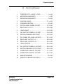
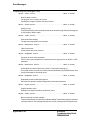
Table of Contents (Cont)
5.3.2
5.4
5.5
5.6
Run Chain 2 ......................................................5-18
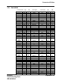
Component Cross Reference .......................... 5-19
List of Circuit Diagrams ................................... 5-21
Component Location Figures .......................... 5-29
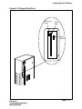
Figure 5-1
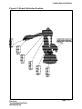
Figure 5-2
Figure 5-3
Figure 5-4
Figure 5-5
Figure 5-6
Figure 5-7
Figure 5-8
Figure 5-9
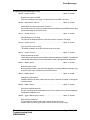
6.
Emergency Stop.....................................................6-3
6.1
6.2
6.3
6.4
6.5
6.6
6.7
Overview .......................................................... 6-3
Emergency Stop - Run Chain 1 ......................... 6-4
Emergency Stop - Run Chain 2 ......................... 6-6
Emergency Stop - Reset Circuit ....................... 6-8
Component Cross Reference ........................... 6-9
List of Circuit Diagrams ................................... 6-11
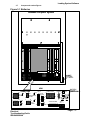
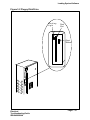
Component Location Figures .......................... 6-15
Figure 6-1
Figure 6-2
Figure 6-3
Figure 6-4
Figure 6-5
7.
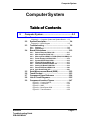
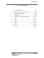
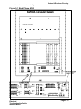
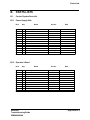
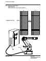
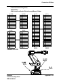
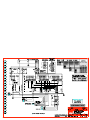
Computer System and System Board..........5-29
Back Plane AP80 ........................................5-31
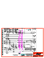
System Board K1CR & K2CR......................5-33
Control Cable XS1 ......................................5-35
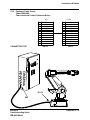
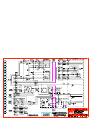
Customer Connections XS3/XT3 & AP41.....5-37
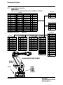
Operator's Panel .........................................5-39
Power Unit ..................................................5-41
R1.MP ........................................................5-43
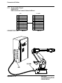
Teach Pendant............................................5-45
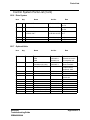
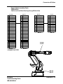
Teach Pendant............................................6-15
Computer System & System Board.............6-17
Back Plane AP80 ........................................6-19
Operator's Panel .........................................6-21
Customer Connections XS3/XT3.................6-23
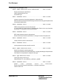
Power Unit ..............................................................7-3
7.1
7.2
7.3
7.4
Overview ..........................................................
KM1 ..................................................................
KM2 ..................................................................
KM3 ..................................................................
7-3
7-4
7-5
7-6
7.5
7.6
7.7
7.8
KM4 .................................................................. 7-8
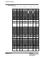
Component Cross Reference ........................... 7-9
List of Circuit Diagrams ................................... 7-11
Component Location Figures .......................... 7-17
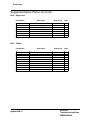
Diagram 7-1 Rectifier Board ....................................... 7-7
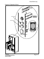
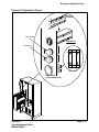
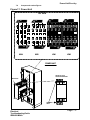
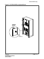
Figure 7-1 Power Unit ..................................................7-17
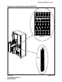
Figure 7-2 XS3/XT3 and Connectors AP41 & AP9........7-19
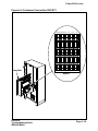
Figure 7-3 K1CR & K2CR on System Board.................7-21
8.
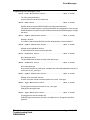
Brake Circuitry .......................................................8-3
8.1
8.2
8.3
8.4
Table of Contents
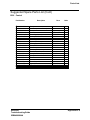
Overview ..........................................................
Manual Brake Release Circuit ...........................
Motors ON Brake Release ................................
Component Cross Reference ...........................
8-3
8-4
8-5
8-7
TOC - III