1
BCM Rls 6.0
WLAN IP Telephony Handset Users
Guide
Task Based Guide
WLAN IP Telephony Handset Users Guide
Copyright © 2010 Avaya Inc.
All Rights Reserved.
Notices
While reasonable efforts have been made to ensure that the information in this document is complete and accurate
at the time of printing, Avaya assumes no liability for any errors. Avaya reserves the right to make changes and
corrections to the information in this document without the obligation to notify any person or organization of such
changes.
Documentation disclaimer
Avaya shall not be responsible for any modifications, additions, or deletions to the original published version of
this documentation unless such modifications, additions, or deletions were performed by Avaya. End User agree to
indemnify and hold harmless Avaya, Avaya’s agents, servants and employees against all claims, lawsuits, demands
and judgments arising out of, or in connection with, subsequent modifications, additions or deletions to this
documentation, to the extent made by End User.
Link disclaimer
Avaya is not responsible for the contents or reliability of any linked Web sites referenced within this site or
documentation(s) provided by Avaya. Avaya is not responsible for the accuracy of any information, statement or
content provided on these sites and does not necessarily endorse the products, services, or information described or
offered within them. Avaya does not guarantee that these links will work all the time and has no control over the
availability of the linked pages.
Warranty
Avaya provides a limited warranty on this product. Refer to your sales agreement to establish the terms of the
limited warranty. In addition, Avaya’s standard warranty language, as well as information regarding support for
this product, while under warranty, is available to Avaya customers and other parties through the Avaya Support
Web site: http://www.avaya.com/support
Please note that if you acquired the product from an authorized reseller, the warranty is provided to you by said
reseller and not by Avaya.
Licenses
THE SOFTWARE LICENSE TERMS AVAILABLE ON THE AVAYA WEBSITE,
HTTP://SUPPORT.AVAYA.COM/LICENSEINFO/ ARE APPLICABLE TO ANYONE WHO DOWNLOADS,
USES AND/OR INSTALLS AVAYA SOFTWARE, PURCHASED FROM AVAYA INC., ANY AVAYA
AFFILIATE, OR AN AUTHORIZED AVAYA RESELLER (AS APPLICABLE) UNDER A COMMERCIAL
AGREEMENT WITH AVAYA OR AN AUTHORIZED AVAYA RESELLER. UNLESS OTHERWISE
AGREED TO BY AVAYA IN WRITING, AVAYA DOES NOT EXTEND THIS LICENSE IF THE
SOFTWARE WAS OBTAINED FROM ANYONE OTHER THAN AVAYA, AN AVAYA AFFILIATE OR AN
AVAYA AUTHORIZED RESELLER, AND AVAYA RESERVES THE RIGHT TO TAKE LEGAL ACTION
AGAINST YOU AND ANYONE ELSE USING OR SELLING THE SOFTWARE WITHOUT A LICENSE. BY
INSTALLING, DOWNLOADING OR USING THE SOFTWARE, OR AUTHORIZING OTHERS TO DO SO,
YOU, ON BEHALF OF YOURSELF AND THE ENTITY FOR WHOM YOU ARE INSTALLING,
DOWNLOADING OR USING THE SOFTWARE (HEREINAFTER REFERRED TO INTERCHANGEABLY
AS "YOU" AND "END USER"), AGREE TO THESE TERMS AND CONDITIONS AND CREATE A
BINDING CONTRACT BETWEEN YOU AND AVAYA INC. OR THE APPLICABLE AVAYA AFFILIATE
("AVAYA").
Copyright
Except where expressly stated otherwise, no use should be made of the Documentation(s) and Product(s) provided
by Avaya. All content in this documentation(s) and the product(s) provided by Avaya including the selection,
arrangement and design of the content is owned either by Avaya or its licensors and is protected by copyright and
other intellectual property laws including the sui generis rights relating to the protection of databases. You may not
modify, copy, reproduce, republish, upload, post, transmit or distribute in any way any content, in whole or in part,
including any code and software. Unauthorized reproduction, transmission, dissemination, storage, and or use
without the express written consent of Avaya can be a criminal, as well as a civil offense under the applicable law.
Third Party Components
Certain software programs or portions thereof included in the Product may contain software distributed under third
party agreements ("Third Party Components"), which may contain terms that expand or limit rights to use certain
portions of the Product ("Third Party Terms"). Information regarding distributed Linux OS source code (for those
Products that have distributed the Linux OS source code), and identifying the copyright holders of the Third Party
Components and the Third Party Terms that apply to them is available on the Avaya Support Web site:
http://support.avaya.com/Copyright.
Trademarks
The trademarks, logos and service marks ("Marks") displayed in this site, the documentation(s) and product(s)
provided by Avaya are the registered or unregistered Marks of Avaya, its affiliates, or other third parties. Users
are not permitted to use such Marks without prior written consent from Avaya or such third party which may own
the Mark. Nothing contained in this site, the documentation(s) and product(s) should be construed as granting, by
implication, estoppel, or otherwise, any license or right in and to the Marks without the express written permission
of Avaya or the applicable third party. Avaya is a registered trademark of Avaya Inc. All non-Avaya trademarks
are the property of their respective owners.
2
NN40011-039 Issue 1.2 BCM Rls 6.0
WLAN IP Telephony Handset Users Guide
Downloading documents
For the most current versions of documentation, see the Avaya Support. Web site: http://www.avaya.com/support
Contact Avaya Support
Avaya provides a telephone number for you to use to report problems or to ask questions about your product. The
support telephone number is 1-800-242-2121 in the United States. For additional support telephone numbers, see
the Avaya Web site: http://www.avaya.com/support
Copyright © 2010 ITEL, All Rights Reserved
The copyright in the material belongs to ITEL and no part of the material may
be reproduced in any form without the prior written permission of a duly
authorised representative of ITEL.
NN40011-039 Issue 1.2 BCM Rls 6.0
3
WLAN IP Telephony Handset Users Guide
Table of Contents
WLAN IP Telephony Handset Users Guide ..................... 6
Overview .......................................................................................... 6
Language ...........................................................................................................6
Wired Equivalent Privacy ...................................................................................6
Loss of signal .....................................................................................................6
IP Phone i2004 mapping ...................................................................................6
Required Information / Equipment ................................................... 7
WLAN Handsets .............................................................................. 8
The WLAN IP Telephony Handset i2010 ...........................................................9
The WLAN IP Telephony Handset i2211 .........................................................10
6120 / 6140 Handset Control ......................................................... 12
Status Indicators 6120/6140 Handsets ............................................................13
WLAN Handsets Buttons and Keys .................................................................14
Navigation of the Digital Mobility Handsets .................................... 15
Handset display ............................................................................. 16
Status area .......................................................................................................16
Information area ...............................................................................................16
Feature options area ........................................................................................17
WLAN Handset and Voice Mail Configuration ............................... 17
Accessing CallPilot Manager via Element Manager ...................... 18
Adding a Subscriber Mailbox ......................................................... 22
Subscriber Mailbox Settings ............................................................................25
Recording Prompts using CallPilot Manager ...................................................28
Initialising a Mailbox .........................................................................................29
Recording Primary or Alternate Greetings .......................................................32
Other Features of the WLAN IP Telephony Handsets ................... 34
Select Ring Type..............................................................................................34
Select Noise Mode ...........................................................................................35
Enter Extension................................................................................................35
Set up Push-to-Talk .........................................................................................36
Adjust Ringer Volume ......................................................................................37
Adjust Speaker Volume ...................................................................................37
Silence the Ringer............................................................................................37
Feature and Function Menus ......................................................... 37
Feature and Function Keys ..............................................................................37
Soft Key Abbreviations menu – MENU key .....................................................38
Function Menu – FCN key ...............................................................................38
Feature Menu – LINE key ................................................................................38
Program Feature Menu Items ..........................................................................39
4
NN40011-039 Issue 1.2 BCM Rls 6.0
WLAN IP Telephony Handset Users Guide
Basic Call Features ........................................................................ 40
Make a Call ......................................................................................................40
Answer Calls ....................................................................................................41
Hold ..................................................................................................................41
Headset ............................................................................................................41
Mute .................................................................................................................41
End calls ..........................................................................................................41
Push-to-Talk .................................................................................. 42
The Call Period ................................................................................................42
Twinning ........................................................................................ 44
Avaya Documentation Links .......................................... 46
NN40011-039 Issue 1.2 BCM Rls 6.0
5
WLAN IP Telephony Handset Users Guide
WLAN IP Telephony Handset Users Guide
Overview
The WLAN IP Telephony Handsets use VoIP technology on IEEE 802.11compliant Wireless LAN. Access Points (APs) use radio frequencies to
transmit signals to and from the WLAN handsets.
The WLAN IP Telephony handsets can be used to make and receive calls as
the user moves throughout the building. The WLAN handsets are used only
on the premises; they are not cellular phones. Just like wired telephones, the
WLAN handsets receive calls directly, receive transferred calls, transfer calls
to other extensions, and make outside and long-distance calls. The DN of the
WLAN handset is obtained directly from the BCM system. Therefore IP
Terminal Clients keycodes are required and IP Terminal Registration must be
enabled on the BCM before the WLAN handset can be registered.
Language
The menus and screens of the WLAN IP Telephony Handsets display in
English only. International characters are supported for BCM prompts,
depending on the market profile. BCM-based prompts display in English,
French, and Spanish.
Wired Equivalent Privacy
The WLAN IP Telephony Handsets support Wired Equivalent Privacy (WEP)
as defined by the 802.11b specification. WEP increases the security of the
wireless LAN to a level similar to a wired Ethernet LAN. WEP is turned on and
off using the APs.
Loss of signal
If a wireless handset is out of range of all APs, it waits 20 seconds for a signal
to be re-established. If a signal is not obtained within 20 seconds, the wireless
handset loses connection to the BCM and any calls are dropped. When the
wireless handset comes back into range of an Access Point, it re-establishes
a connection to the BCM and goes through the system registration process.
IP Phone i2004 mapping
The WLAN IP Telephony Handsets emulate the IP Phone 2004. All IP Phone
2004 functions and messaging features are supported, where possible. The
speakerphone function and functions that require use of the volume keys are
not supported.
6
NN40011-039 Issue 1.2 BCM Rls 6.0
WLAN IP Telephony Handset Users Guide
The large screen area of the IP Phone 2004 and its numerous keys are
mapped onto the smaller screen and fewer buttons of the wireless handsets.
The button mapping from the IP Phone 2004 to the WLAN Handsets is
designed to preserve nearly all of the functionality of the IP Phone 2004 within
a small, mobile device.
Required Information / Equipment
Ensure that the WLAN IP Telephony Manager 2245 has been installed and
configured successfully and that the WLAN IP handsets have been registered
and subscribed to the system.
Equipment required and already installed should include:
WLAN IP Telephony IP Telephony Manager 2245
WLAN IP Telephony Applications Gateway (OAM) 2246 (optional)
Wireless LAN 802.11b compliant Access Points
DHCP Server (optional)
TFTP Server
Syslog Server (optional)
NN40011-039 Issue 1.2 BCM Rls 6.0
7
WLAN IP Telephony Handset Users Guide
WLAN Handsets
The supported WLAN handsets are illustrated below.
WLAN Handset 6120
8
WLAN Handset 6140
NN40011-039 Issue 1.2 BCM Rls 6.0
WLAN IP Telephony Handset Users Guide
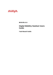
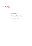
The WLAN IP Telephony Handset i2010
Earpiece
Display
Up
Select
Down
Menu
Soft Keys
Power on /
Start Call
Power off /
End Call
Line
Function
Microphone
Headset Jack
NN40011-039 Issue 1.2 BCM Rls 6.0
9
WLAN IP Telephony Handset Users Guide
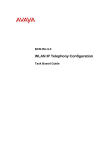
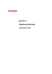
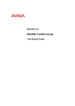
The WLAN IP Telephony Handset i2211
Earpiece
Display
Push to
Talk
(Radio)
Up
Select
Down
Menu
Soft Keys
Power off /
End Call
Power on /
Start Call
Battery
Release
Line
Function
Microphone
Headset Jack
10
NN40011-039 Issue 1.2 BCM Rls 6.0
WLAN IP Telephony Handset Users Guide
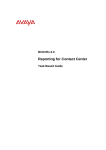
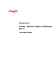
The WLAN IP Telephony Handset i2212
NN40011-039 Issue 1.2 BCM Rls 6.0
11
WLAN IP Telephony Handset Users Guide
The WLAN IP Telephony Handsets 6120/6140
6120 / 6140 Handset Control
Press and hold the End
button to turn your WLAN Handset
6120 and 6140 off.
This key also affects some of the states of the handset.
Press the End button to terminate an active call.
Press the Start
Press the Line
button to access the key labels for line
appearances and line features.
12
button to place a call.
Press FCN
to open the Features list when in the active (idle)
state. Other handset functions are accessed via the Actv soft key.
Soft keys are located below the display area. Use the four Soft keys to
activate the displayed softkey feature.
Use the navigation cluster buttons and Enter button to navigate and
activate the various menu options.
NN40011-039 Issue 1.2 BCM Rls 6.0
WLAN IP Telephony Handset Users Guide
Status Indicators 6120/6140 Handsets
Signal strength indication
New Voice Message
Battery charge. When only one level remains, the battery pack must be
recharged.
Active speakerphone
Current line in use
Up and down arrows are displayed when the menu has additional
options above or below. Left or right arrows are displayed during
editing.
Incoming Call
Incoming call from Messaging Application
Incoming Push to Talk call (This feature is available only on the WLAN
Handset 6140)
Muted
Locked
No Service
The priority PTT ring icon indicating an incoming call on the priority
PTT channel. This call overrides any other calls.
Muted softkey pressed
Keypad Locked
The no service indicator indicates that you are out of the coverage area
and cannot receive or place calls
Indicates that the handset is downloading code.
The ring indicator icon is used to display the Real-Time Location
System (RTLS) icon, indicating that the administration option has been
set to ON. An incoming call, triggering the ring indicator icon, takes
priority over the RTLS icon.
For full detailed instructions relating to the use of 6120 and 6140 handsets
please refer to the WLAN Handset 6120 and WLAN Handset 6140 User
Guide
NN40011-039 Issue 1.2 BCM Rls 6.0
13
WLAN IP Telephony Handset Users Guide
WLAN Handsets Buttons and Keys
Key Reference
Key
Description
A
Power On/Start Call key
Turns on the handset.
B
Power Off/End Call key
Ends an active call and turns off the
handset.
Feature and Display soft keys
The first of the four soft keys is the
Feature soft key, which starts or ends a
feature. The next three soft keys are
Display keys, which show feature options.
Menu key
Displays the full description of the Display
soft keys abbreviations and
accesses the handset features.
Function key
Accesses handset functions when in
active (idle) state.
The Function key also provides access
to the User Option menu in the standby
state.
Line key
Accesses the Feature menu.
C
D
E
F
H
Up, Down, and Select buttons
Enables you to navigate and activate the
various menu options.
Adjusts the speaker and ringer volume.
Push-to-Talk button
Push-to-Talk is available on the WLAN
Handset 2211 only.
Activates the Push-to-Talk feature on the
WLAN Handset 2211
14
NN40011-039 Issue 1.2 BCM Rls 6.0
G
WLAN IP Telephony Handset Users Guide
Key Reference
Key
Description
Left arrow and Star button
Enables scrolling to the left for menu
navigation.
Right arrow and Pound button
Enables scrolling to the right for menu
navigation.
I
J
Navigation of the Digital Mobility Handsets
Softkeys
Power On / Start Call
Key (
Display
)
Info key when on an
active call
Menu Key (MENU)
Pressing and holding
this key for 3 seconds
enters the text message
menu (MSF-MAIL)
Power Off / Disconnect
Key (
)
This key is also used to
turn on the handset
Function Key (FCN )
NN40011-039 Issue 1.2 BCM Rls 6.0
15
WLAN IP Telephony Handset Users Guide
Handset display
There are three areas to the WLAN Handset display:
Status area
Information area
Feature options area
The following figure shows an example of the WLAN Handset display.
Status area
Information Text
5
Feature Options area
Ftre
Status area
The status area displays the handset status. It can include:
status indicators (see the table below)
left and right arrows
a series of dots representing the line keys, which change to a number
when active
No Service
You are outside the coverage area and cannot receive or place
calls. An audible alarm also sounds. Return to the coverage area to
re-establish the connection.
Your battery pack charge is low. An audible beep also sounds.
Replace your battery pack within two minutes.
You have a new voicemail message.
Melody
A melody is played when the WLAN Handset is turned on for the
first time following a completed charge.
Information area
The Information area shows:
the extension number of the handset
a line for general information
features and call information when the handset is in use
16
NN40011-039 Issue 1.2 BCM Rls 6.0
WLAN IP Telephony Handset Users Guide
Feature options area
When a feature is activated, or when you are on an active call, the Feature
options area shows you the action you must take to proceed. For example:
Pswd. This means you must enter your mailbox password.
The Feature options area shows the label for the Ftre soft key and for the
three display soft keys.
These button labels appear directly above the Feature and display soft keys,
and to the right of the Ftre label on the display. These button labels vary,
depending on the feature in use.
Note: The WLAN Handset does not support scrolling. Therefore any features
that require the ability to scroll are not supported.
WLAN Handset and Voice Mail Configuration
WLAN IP Telephony IP handsets have the ability to access Voice Mail
mailboxes for both internal, stand-alone systems, and external voice mail
systems accessed over a private network (as with MCDN).
The WLAN handset can be configured to have a voicemail box. The voicemail
box can be configured within the BCM’s CallPilot Manager interface.
NN40011-039 Issue 1.2 BCM Rls 6.0
17
WLAN IP Telephony Handset Users Guide
Accessing CallPilot Manager via Element Manager
1. To access the Business Element Manager application from the Start
Menu,
navigate
to
Start,
Programs,
Avaya,
Business
Communications Manager, Business Element Manager.
2. Alternatively, double-click on the Business Element Manager desktop
icon.
18
NN40011-039 Issue 1.2 BCM Rls 6.0
WLAN IP Telephony Handset Users Guide
3. You will be presented with the Element Manager interface.
4. Open the Network Elements folder and select the IP Address of the
BCM.
5. Enter the User Name of the BCM in the User Name field, by default this
is nnadmin. Then enter the Password in the Password field, by default
the password is PlsChgMe!. Click the Connect button.
NN40011-039 Issue 1.2 BCM Rls 6.0
19
WLAN IP Telephony Handset Users Guide
6. A warning screen will appear, read the warning and click OK.
7. You will be presented with the Element Manager interface.
20
NN40011-039 Issue 1.2 BCM Rls 6.0
WLAN IP Telephony Handset Users Guide
8. To access CallPilot Manager: Select the Configuration tab, open the
Applications folder, select the Voice Messaging / Contact Center
link, and then click to Launch CallPilot Manager.
9. You will be presented with a Security Alert Screen. Read the alert and
click Continue to this website to continue.
NN40011-039 Issue 1.2 BCM Rls 6.0
21
WLAN IP Telephony Handset Users Guide
10. The Main Menu of CallPilot Manager will be launched.
Adding a Subscriber Mailbox
Create a Subscriber Mailbox for all users that need to be able to receive
messages from their physical telephone extension. It is recommended to
make the Mailbox number the same as the extension number it is being
assigned to.
Subscriber Mailboxes must be initialised before they can receive messages.
Until this is done, calls will be redirected to the General Delivery Mailbox
instead. (Please refer to the Initialising a Mailbox section of this guide.)
1. Click the Mailbox Administration heading.
2. Click the Add Mailbox link. The Add Mailbox page appears.
22
NN40011-039 Issue 1.2 BCM Rls 6.0
WLAN IP Telephony Handset Users Guide
3. In the Mailbox box, type the mailbox number.
Available Mailboxes,
are dictated by the
Keycode purchased
and currently created
mailboxes
4. From the Mailbox Type list box, select Subscriber. Click the Submit
button.
NN40011-039 Issue 1.2 BCM Rls 6.0
23
WLAN IP Telephony Handset Users Guide
5. The Subscriber Mailbox page appears. The Subscriber Mailbox
page appears. Configure the Subscriber Mailbox properties as
required. Click Submit when complete. A description of these
properties is provided in the below table.
24
NN40011-039 Issue 1.2 BCM Rls 6.0
WLAN IP Telephony Handset Users Guide
Subscriber Mailbox Settings
Attribute
Extension
Last Name
First Name
Class Of Service
Find Me/ Follow
Me
Display in
Directory
Enable Message
Waiting
Enable Auto Login
Outdial Type
Alternate Ext 1,2,
3, 4, 5
Enable Call
Screening
Express
Messaging Line
(Fax Only)
Enable Mailbox
Restrictions
Park & Page
Description
The extension that the mailbox will be assigned to. It is generally good
practice to match the mailbox number to the extensions number.
Last name of the mailbox owner.
First name of the mailbox owner.
Class of Service assigned to the mailbox.
Click Change to add/edit any of the Find Me/ Follow Me schedules or
external number entries.
Clear this if you do not want the mailbox owner’s name to appear in the
Company Directory.
Clear this if you do not want message notification to appear on the
mailbox owner’s telephone display.
Auto-Login speeds up the login process for subscribers. With AutoLogin, subscribers can log on from their primary or alternate telephone
without having to enter their mailbox number or password.
This setting provides an external access resource for certain mailbox
features. Outdial is required for features such as Reply, Off-Premise
Notification, Outbound Transfer etc.
Select None if you do not want to assign outdialing capabilities
Select Line and type the line number. Line numbers must be
between 1 - 999 for BCM450 and 1-332 for BCM50.
Select Pool and type the line pool number or letter.
Select Route if, for example routing is used to access a PRI line
pool.
Allows the designated extension direct access to the mailbox, in
addition to Message Waiting Indication when messages are left in the
mailbox. Maximum of 5 Alternate Extension for a single mailbox.
Select this to assign screened transfers (via the Auto-Attendant) to the
mailbox owner
Any calls to this line will be immediately transferred to the mailbox. Note
that if you enter an Express Messaging Line (e.g. a Target Line), that
line cannot appear/ring at any extension. Also, the Voicemail (F985) DN
should be set as the Prime set for that line (see Telephony Services,
Lines).
If the mailbox will use Express Messaging Line, enabling this option
stops the greeting being played to calls to the Express Messaging Line,
making the fax call quicker.
You can control how a subscriber accesses a mailbox. If you select the
Enable Mailbox Restrictions check box, a subscriber cannot log in to the
mailbox externally. If the subscriber attempts to log in externally, the
prompt "You are not allowed to use this feature. Exiting the system,
goodbye.‖ is played. The system disconnects the caller.
In addition, an internal subscriber cannot administer a restricted
mailbox. If the subscriber presses 8, the prompt "You are not allowed to
use this feature" plays and the subscriber returns to the main
Menu. Mailbox restrictions are applicable only to subscriber mailboxes.
With Park and Page, external callers can press 6 to page a mailbox
subscriber while they listen to the subscriber’s personal greeting or
record a message. When the caller presses 6, the system parks the call
and pages to paging zone or overhead paging system, or both and the
caller hears ―One moment, please.‖ The caller cannot interrupt this
prompt by pressing DTMF. The page is repeated based on the mailbox
configuration until the parked call is picked up or the park timeout
occurs, at which point the caller is returned to the mailbox and hears the
subscriber’s personal greeting. The call is parked as long as there are
not already 25 calls parked. If the call cannot be parked, the caller hears
―The person you have called is not available‖ followed by the
NN40011-039 Issue 1.2 BCM Rls 6.0
25
WLAN IP Telephony Handset Users Guide
Attribute
Page Type
Paging Zone
Page Retries
Retry Interval
Find Me/Follow Me
disabled for Hunt
Groups
Description
subscriber’s mailbox greeting. While a call is parked the caller hears a
hold tone or music on hold, depending on the system configuration. The
call is paged to the appropriate paging zone or overhead speaker
system, or both. If the page is unsuccessful because the paging facility
is busy with another page, the system waits five seconds and retries the
page every five seconds until the paging facility is available or the call
park timeout expires, whichever occurs first. If the call park timeout
expires first, the caller hears ―The person you have called is not
available‖ followed by the subscriber’s mailbox greeting. If the page is
unsuccessful for any other reason, the call is un-parked and the caller
hears ―The person you have called is not available‖ followed by the
subscriber’s mailbox greeting. While a call is being paged, the system
plays the mailbox spoken name and park string, for example ―John Doe,
101.‖ The park string is played in the standard voice prompts, or
customized digits, if you recorded them.
Select the required paging type facility. The choices are Internal Zone,
Overhead Paging, Both or None. The default is none.
Select the Paging Zone to which the paging announcement will be
played. The zones available are zone 1, 2, 3, 4, 5, 6 or All. The default
is 1. If the paging type is overhead paging this setting is ignored.
Select the number of page retries to be played to the Page Zone from
the box select 0, 1, 2, 3, 4 or 5. The default is 1.
The retry interval is the number of seconds between paging retries. The
range is 5-300 seconds. The default is 15 seconds.
If a Find Me/Follow Me user is a member of a Hunt Group, enabling this
option will stop Hunt Group calls at the FM/FM user’s extension from
being forwarded to FM/FM destinations.
6. The created mailbox will be displayed.
26
NN40011-039 Issue 1.2 BCM Rls 6.0
WLAN IP Telephony Handset Users Guide
7. You can now record the Spoken (Company) Name for the mailbox
although this is optional at this stage click on the Change link for the
mailbox, to record the spoken name.
Note: The spoken (Company) name can also be recorded when initialising a
mailbox. Refer to the Initialising a Mailbox section of this guide for more
information.
8. Click on the Voice link and follow the instructions detailed in the
Recording Prompts using CallPilot Manager section of this guide.
NN40011-039 Issue 1.2 BCM Rls 6.0
27
WLAN IP Telephony Handset Users Guide
Recording Prompts using CallPilot Manager
This section describes how to record mailbox Company Directory names, and
Group List names using the CallPilot Manager interface on the PC.
For best results, use a telephone that is attached to the same switch as your
voicemail system. Avoid using wireless telephones.
1. When displayed, click the Voice link. The page you can record
greetings and prompts from appears.
2. In the Connect to box, type the extension number or telephone
number you are using to record the greeting or prompt. For a local
extension, just type the extension number. For a telephone number that
is not a local extension, type the sequence of digits that dial the
telephone number from the voicemail system. For example, you might
need to dial 9, the area code, and then the telephone number.
3. Click the Dial button.
4. The telephone rings.
5. Pick up the handset. Do not use Handsfree.
28
NN40011-039 Issue 1.2 BCM Rls 6.0
WLAN IP Telephony Handset Users Guide
6. After the tone, record your prompt.
7. After you finish recording your prompt, click the Stop button.
8. To listen to the prompt, click the Play button or to save the recording,
click the Save button.
9. Click the Close button and replace your telephone handset.
The handsets are administered by combinations of keys that can be used to
navigate the configurable options available for each handset. The following
illustration will describe how the handset options can be used for example to
configure and initialize a voicemail box assigned against the WLAN extension.
Initialising a Mailbox
Once the Subscriber mailbox has been created for the Digital Mobile handset,
the mailbox owner must initialise it before it can receive voice messages. This
involves changing the default mailbox Password to a new user Password and
recording the mailbox owners name in the Company Directory. This can be
done from the Digital Mobile Handset in the same way as you would initialise
the mailbox from a BCM digital desk set.
1. Press the Start Call key on the WLAN handset, then press Ftre
followed by 981
NN40011-039 Issue 1.2 BCM Rls 6.0
29
WLAN IP Telephony Handset Users Guide
2. On the soft keys, enter the password of 0000 if the mailbox is to be
assigned against this extension.
3. If you are assigning the mailbox to another extension select OTHR and
entering the Mailbox number and password as a single string of digits
for example 2120000 (mailbox 212 default password 0000). Then press
the soft key under OK or press the # key.
4. You will be prompted in the display to change your password Must
change pswd.
30
NN40011-039 Issue 1.2 BCM Rls 6.0
WLAN IP Telephony Handset Users Guide
5. Enter a new password from 4 to 8 digits long that does not start with
―0‖, and press OK or #.
6. You will now be required to confirm the new password. Re-enter your
new mailbox password and press OK or #.
7. You will be prompted to record your name. At the tone, record your
name in the Company Directory. It is recommended that you include
your mailbox number in the recording, for example, ―Ed Jones, mailbox
5354.‖
NN40011-039 Issue 1.2 BCM Rls 6.0
31
WLAN IP Telephony Handset Users Guide
8. Press OK or # to end the recording.
9. Press OK or # to accept the recording or press PLAY or 1 to listen to
the recording or press RETRY or 2 to re-record your name.
10. Press the Release key to end the session.
Recording Primary or Alternate Greetings
Only a Primary mailbox greeting is necessary, but you can record an Alternate
mailbox greeting for times when you are out of the office, such as holidays. If
you do not record any mailbox greetings, your Company Directory name
recording plays to callers who reach your mailbox.
1. On a WLAN handset press Ftre followed by 981
2. Follow the voice prompts or the display button options to open your
mailbox.
3. Open the Greeting options menu: Press ADMI or 8 then Press GREE
or 2.
4. Press REC or 1. Press PRIM to record the Primary greeting, press ALT
to record the Alternate greeting or PERS to record a Personal greeting.
32
NN40011-039 Issue 1.2 BCM Rls 6.0
WLAN IP Telephony Handset Users Guide
5. If you are changing a greeting, the current greeting starts to play. If this
is the first time you are recording a greeting, Not recorded appears
briefly.
6. You will be prompted to record a new greening. Press YES or 1 and
record you’re greeting at the tone.
7. Press OK or # to end the recording. Press OK or # to accept the
recording or press PLAY or 1 to listen to the greeting or press RETRY
or 2 to re-record the greeting.
NN40011-039 Issue 1.2 BCM Rls 6.0
33
WLAN IP Telephony Handset Users Guide
8. Press the Release key to end the session.
Other Features of the WLAN IP Telephony Handsets
Select Ring Type
The Ring Type option enables you to set the WLAN Handset ringing cadence.
1. Press
when in the standby state.
2. Press the Up and Down buttons to scroll through the menu and
highlight Ring Options.
3. Press the Select button (or OK) to select Ring Options.
4. Press the Up and Down buttons to scroll through the menu and
highlight Telephone Ring.
5. Press the Select button (or OK) to select Telephone Ring.
6. Press the Up and Down buttons to scroll through the menu and
highlight Ring Cadence.
7. Press the Select button (or OK) to select Ring Cadence.
8. Scroll to one of the desired options:
a. Off — ringer is turned off.
b. PBX — ringing uses the distinctive ringing pattern sent to the
handset from the call server.
c. Continuous — ringing is continuous.
d. Short Pulse — ringing occurs in short bursts.
e. Long Pulse — ringing occurs in long bursts.
9. Press the Select button (or OK) to select the highlighted option.
10. Press UP to return to the previous menu and set another option.
11. Press
to exit all menus and return to the standby state.
You can also press Exit from the top-level menu to exit the menu and return to
the active (off-hook) state.
34
NN40011-039 Issue 1.2 BCM Rls 6.0
WLAN IP Telephony Handset Users Guide
Select Noise Mode
The Noise Mode option enables you to adjust the WLAN Handset for different
levels of noise within the working environment.
1. Press
when in the standby state.
2. Press the Up and Down buttons to scroll through the menu and
highlight Phone Options.
3. Press the Select button (or OK) to select Phone Options.
4. Press the Up and Down buttons to scroll through the menu and
highlight Noise Mode.
5. Press the Select button (or OK) to select Noise Mode.
6. Press the Up and Down buttons to scroll through the menu and
highlight one of the following settings:
a. Normal — For most office environments (default).
b. High — For moderate background noise.
c. Severe — For extremely noisy conditions.
7. Press the Select button (or OK) to select the highlighted setting.
8. Do one of the following:
a. Press UP to return to the previous menu and set another option.
b. Press
to exit all menus and return to the standby state.
You can also press Exit from the top-level menu to exit the menu and return to
the active (off-hook) state.
Enter Extension
The Extension option enables the user to enter the extension number for the
WLAN Handset. This number is used to identify the handset. It displays when
the handset is in the standby state.
Note: It is recommended that you enter the Directory Number (DN) of the
system or the full number of your handset. When the WLAN Handset is in the
active (idle) state the DN of the system is displayed.
1. Press
when in the standby state.
2. Press the Up and Down buttons to scroll through the menu and
highlight Extension.
3. Press the Select button (or OK) to select Extension.
NN40011-039 Issue 1.2 BCM Rls 6.0
35
WLAN IP Telephony Handset Users Guide
4. Enter the extension number using the handset keypad.
5. Press Save to save your extension number.
6. Do one of the following:
a. Press UP to return to the previous menu and set another option.
b. Press
to exit all menus and return to the standby state.
You can also press Exit from the top-level menu to exit the menu and return to
the active (off-hook) state.
Set up Push-to-Talk
Push-to-Talk is available on the WLAN Handsets 2211 and 6140 only.
Push-to-Talk mode enables two-way radio communication with another WLAN
Handset 2211 user. You can enable/disable Push-to-Talk mode and select a
channel.
1. Press
when in the standby state.
2. Press the Up and Down buttons to scroll through the menu and
highlight Push-to-Talk.
3. Press the Select button (or OK) to select Push-to-Talk.
4. Press the Up and Down buttons to scroll through the menu and
highlight one of the following settings:
a. Enable: Enables Push-to-Talk mode.
b. Disable: Disables Push-to-Talk mode.
5. Press the Select button (or OK) to select the setting.
6. If enabled, select a channel (1 to 8).
7. Do one of the following:
a. Press UP to return to the previous menu and set another option.
b. Press
to exit all menus and return to the standby state.
You can also press Exit from the top-level menu to exit the menu and return to
the active (off-hook) state.
36
NN40011-039 Issue 1.2 BCM Rls 6.0
WLAN IP Telephony Handset Users Guide
Adjust Ringer Volume
You can increase or decrease the ringer volume of the WLAN Handset 2211
only. To adjust the ringer volume, press the Up or Down button while the
handset is ringing.
Adjust Speaker Volume
You can increase or decrease the speaker volume of the WLAN Handset.
To adjust the speaker volume, press the Up or Down button while in a call.
Silence the Ringer
You can silence (or mute) the WLAN Handset ringer.
To silence the ringer, press
while the handset is ringing.
Feature and Function Menus
You can view the features and functions programmed in your system using
various menus, soft key features, and the Line (DN) features. You can access
some functions and features using one or more or the methods described in
this section.
Feature and Function Keys
The following table lists the features and functions available on the WLAN
Handset, along with their key sequence.
Key Sequence
FCN + 1
Feature / Function
Mute
FCN + 2
FCN + 3
FCN + 4
FCN + 5
FCN + 6
FCN + 7
FCN + 8
Hold
Goodbye
Directory
Inbox
Outbox
Quit
Copy
LINE + 1
LINE + 2
LINE + 3
LINE + 4
LINE + 5
LINE + 6
Intercom
Intercom
Page - General
Last Number Redial
Conference Call
Call Forward
NN40011-039 Issue 1.2 BCM Rls 6.0
37
WLAN IP Telephony Handset Users Guide
Soft Key Abbreviations menu – MENU key
Use the Soft Key Abbreviations menu to view the full description of the soft
key abbreviations and access the WLAN Handset features.
Activate a feature
1. Place the handset in the active (idle) or active (off-hook) state.
2. Press
to view the Soft Key Abbreviations menu.
3. Press the Up and Down buttons to scroll through the list of features.
The full description is highlighted in the display area.
4. Do one of the following:
a. Press the Select button (or OK) to activate the highlighted
feature.
b. Press the appropriate number key. The feature does not have to
be highlighted.
Function Menu – FCN key
Use the Function menu to view and activate the WLAN Handset functions.
Activate a function
1. Place the handset in the active (idle) or active (off-hook) state.
2. Press
to display the first four functions in the display area.
3. Press the Up and Down buttons to scroll through the list of functions.
The abbreviation is highlighted in the display area.
4. Do one of the following:
a. Press the Select button (or OK) to activate the highlighted
feature.
b. Press the appropriate number key. The feature does not have to
be highlighted.
Feature Menu – LINE key
Use the Feature menu to view and activate the WLAN Handset line features.
These features are programmed on each handset using the six line keys
(number keys 1 through 6).
Note: A feature must be available on the system before it can be programmed
on a handset.
38
NN40011-039 Issue 1.2 BCM Rls 6.0
WLAN IP Telephony Handset Users Guide
Activate a feature
1. Place the handset in the active (idle) or active (off-hook) state.
2. Press
to view the first screen of the Feature menu. Press
to view the second screen.
again
3. Press the Up and Down buttons to scroll through the list of features.
The abbreviation is highlighted in the display area.
4. Do one of the following:
a. Press the Select button (or OK) to activate the highlighted
feature.
b. Press the number key (1 through 6) corresponding to the
desired feature. The feature does not have to be highlighted.
Program Feature Menu Items
You must be in the active (off-hook) state to program a Feature menu item.
External autodial
1. Press Feature *1.
2. Press
and a number key (1 through 6) corresponding to an
available key.
3. Dial the external number, including routing codes.
4. Press OK to store the number.
Internal autodial
1. Press Feature *2.
2. Press
and a number key (1 through 6) corresponding to an
available key.
3. Dial the extension number.
4. Press OK to store the number.
Features
1. Press Feature *3.
2. Press
and a number key (1 through 6) corresponding to an
available key.
3. Press Feature and enter the feature code.
NN40011-039 Issue 1.2 BCM Rls 6.0
39
WLAN IP Telephony Handset Users Guide
4. Press OK to store the feature code.
Erase memory buttons
1. Press Feature *1.
2. Press
and a number key (1 through 6) corresponding to an
available key.
3. Press OK to erase the button.
Basic Call Features
You can make external and internal calls using the following features:
Make a call
Answer a call
Hold a call
Use the headset
Mute a call
Make a Call
There are many ways to make a call, depending on your handset
programming and the type of call.
External calls using line keys
1. Press
2. Press
to go off-hook.
to access the Feature menu.
3. Press a number key (1 through 6) corresponding to the desired line
key.
4. Dial the external number.
External calls using intercom keys
1. Press
2. Press
to go off-hook.
to access the Feature menu.
3. Press a number key (1 through 6) corresponding to the desired
intercom key and enter a line pool access code or destination code.
4. When you hear an external dial tone, dial the external number.
40
NN40011-039 Issue 1.2 BCM Rls 6.0
WLAN IP Telephony Handset Users Guide
Note: Contact your system administrator for a list of line pool codes. PRI lines
do not support line pool access codes; they must be configured as a
destination code. When entering a destination code on PRI lines
you will not hear dial tone.
Internal calls using intercom buttons
1. Press
2. Press
to go off-hook.
to access the Feature menu.
3. Press a number key (1 through 6) corresponding to the desired
intercom key.
4. Dial the extension number.
Answer Calls
When your handset rings or vibrates, a line number on the display flashes,
and the display shows information about the call, such as the caller’s name
and extension:
Press
.
Hold
While on a call, press
flashes.
To retrieve a held call, press
, while in the active (off-hook) state.
Then press the number key corresponding to the flashing line number.
and 2.The indicator for the line on hold
Headset
You must have a headset installed on your handset to use this feature.
Connect the headset to the headset jack.
To answer a call with a headset plugged into your handset, press any
key other than Power On/Start Call, Power Off/End Call, the soft
keys, or the Up/Down/Select buttons.
Mute
While on a call, press
and 1 to turn the microphone off.
Do the same again to turn the microphone on.
End calls
You must end every call, by pressing the Power Off/End Call key, to release
system resources and allow the WLAN Handset to function properly.
NN40011-039 Issue 1.2 BCM Rls 6.0
41
WLAN IP Telephony Handset Users Guide
If this is not done, it will result in the ringer not ringing for the next call and you
might miss an important call.
Push-to-Talk
Push-to-Talk is available on the WLAN Handset 2211 only.
Push-to-Talk mode enables WLAN Handsets 2211 to operate in a group
broadcast mode in addition to the standard handset operation. The WLAN
Handset 2211 supports eight multicast channels with the current channel
saved in the handset memory.
The Call Period
Push-to-Talk mode operates on the concept of a call period. The Push-to-Talk
call period begins with the first transmission and ends when there has been
no two-way radio traffic on the channel for 10 seconds.
The Push-to-Talk mode controls the handset keypad during the call period.
Therefore, it is not possible to use the keypad for any other functions.
However, it is possible to place and receive telephone calls.
Initiate a Push-to-Talk call
1. Press the Push-to-Talk button on the right side of the handset. The
―start transmit‖ tone sounds within two seconds. The channel is active
and the display screen shows the current active channel.
2. Speak into the handset’s microphone. All WLAN Handsets 2211 that
are monitoring that channel hear the transmission.
3. Release the Push-to-Talk button. The ―end transmit‖ tone sounds.
The handset enters the waiting state, where it monitors the channel for
up to 10 seconds.
Receive a Push-to-Talk transmission
Upon receiving a Push-to-Talk transmission, the ―receiving alert‖ tone sounds
and the WLAN Handset 2211 enters the receive state.
In this state, the handset receives all conversations on the selected channel.
The display shows the current active channel, the caller ID of the current
transmitter, and an indication that the handset is receiving a broadcast
transmission.
At the end of a transmission, the handset enters the waiting state, where it
monitors the channel for up to 10 seconds and displays ―Waiting‖ on the
screen. If no other transmission occurs within 10 seconds, the ―end call‖ tone
sounds and the handset becomes idle.
42
NN40011-039 Issue 1.2 BCM Rls 6.0
WLAN IP Telephony Handset Users Guide
Respond to a Push-to-Talk call
1. When you hear a transmission, press the Push-to-Talk button on the
right side of the handset. The ―start transmit‖ tone sounds. Since all
handsets on that channel are already in the receive state, there is no
two-second delay.
2. Speak into the handset’s microphone. If no transmission occurs during
the 10-second countdown period, the ―end call‖ tone sounds and the
handset becomes idle.
Change the Push-to-Talk volume
Use the Up and Down buttons to increase or decrease volume.
A separate volume is maintained in Push-to-Talk mode.
Mute a current Push-to-Talk call
Mute affects only the current call. When the next call period starts, the audio is
automatically unmuted. Mute does not allow the user to use the handset’s
keypad for anything else.
1. Press the Mute soft key. The following prompt displays: Mute Two-Way
Radio?
2. Press the Yes soft key to mute the call. The prompt disappears after
three seconds if there is no response.
Unmute a Push-to-Talk call
1. Press the Unmute soft key. The following prompt displays: Unmute
Two-Way Radio?
2. Press the Yes soft key to unmute the call. The prompt disappears after
three seconds if there is no response.
End a Push-to-Talk call
Only the current call is terminated for this WLAN Handset 2211. When the
next call period starts, the handset is again in the receive state. You can rejoin
a still-active session by initiating a Push-to-Talk call.
1. Press the Terminate soft key. The following prompt displays:
Terminate Two-Way Radio?
2. Press the Yes soft key to end the call. Push-to-Talk audio is
immediately stopped and the handset returns to regular mode.
Answer a call during a Push-to-Talk call
An incoming call can be answered while in a Push-to-Talk call. To announce
an incoming call, the WLAN Handset 2211 rings with a low-volume ring and
displays a system message.
NN40011-039 Issue 1.2 BCM Rls 6.0
43
WLAN IP Telephony Handset Users Guide
1. Press
. The Push-to-Talk session is pre-empted.
2. After the call is over, press as usual to go back on-hook. The Push-toTalk session goes out of pre-empted mode and becomes active again.
If an active Push-to-Talk call has not ended, the audio is heard again.
Make a call during a Push-to-Talk call
A call can be made while in a Push-to-Talk call.
1. Press
. The Push-to-Talk session is pre-empted.
2. After the call is over, press as usual to go back on-hook. The Push-toTalk session goes out of pre-empted mode and becomes active again.
If an active Push-to-Talk call has not ended, the audio is heard again.
Twinning
The WLAN handsets have the ability to be twinned to a BCM digital desk set,
so that when a call is sent to the Digital desk set, the WLAN handset also
rings. The programming for this is done under Unified Manager.
1. Log into the BCM Element Manager main configuration screen. From
the Configuration tab open the Telephony folder followed by the
Sets folder and select the All DN’s link.
2. Scroll down to the WLAN DN number that you wish to have twinned.
Select the DN number, then open the sub menu for Answer DN’s.
44
NN40011-039 Issue 1.2 BCM Rls 6.0
WLAN IP Telephony Handset Users Guide
3. Click the Add button. The Add Answer DNs dialogue box will be
presented. In here type the DN number of the Digital Desk set that the
WLAN handset is to be twinned with, then press the OK button.
4. The WLAN handset will now ring whenever a call is placed to the
Digital desk set.
NN40011-039 Issue 1.2 BCM Rls 6.0
45
WLAN IP Telephony Handset Users Guide
Avaya Documentation Links
46
WLAN IP Telephony and Installation guide
WLAN IP Handset 2210/2211/2212 User guide
WLAN Handset 6120 and WLAN Handset 6140 User Guide
Installation – Devices guide
CallPilot Manager Set Up and Operation Guide
NN40011-039 Issue 1.2 BCM Rls 6.0