1
Enterasys® SecureStack™ B2
Stackable Switches
Configuration Guide
Firmware Version 4.02.xx.xxxx
P/N 9034133-15
Notice
Enterasys Networks reserves the right to make changes in specifications and other information contained in this document and its web site without prior notice. The reader should in all cases consult Enterasys Networks to determine whether any such changes have been made.
The hardware, firmware, or software described in this document is subject to change without notice.
IN NO EVENT SHALL ENTERASYS NETWORKS BE LIABLE FOR ANY INCIDENTAL, INDIRECT, SPECIAL, OR CONSEQUENTIAL DAMAGES WHATSOEVER (INCLUDING BUT NOT LIMITED TO LOST PROFITS) ARISING OUT OF OR RELATED TO THIS DOCUMENT, WEB SITE, OR THE INFORMATION CONTAINED IN THEM, EVEN IF ENTERASYS NETWORKS HAS BEEN ADVISED OF, KNEW OF, OR SHOULD HAVE KNOWN OF, THE POSSIBILITY OF SUCH DAMAGES.
Enterasys Networks, Inc.
50 Minuteman Road
Andover, MA 01810
© 2008 Enterasys Networks, Inc. All rights reserved.
Part Number: 9034133‐15 October 2008
ENTERASYS, ENTERASYS NETWORKS, ENTERASYS SECURE NETWORKS, SECURESTACK, ENTERASYS SECURESTACK, ENTERASYS NETSIGHT, WEBVIEW, and any logos associated therewith, are trademarks or registered trademarks of Enterasys Networks, Inc. in the United States and other countries. For a complete list of Enterasys trademarks, see http://www.enterasys.com/company/trademarks.aspx.
All other product names mentioned in this manual may be trademarks or registered trademarks of their respective companies.
Documentation URL: http://www.enterasys.com/support/manuals
Documentacion URL: http://www.enterasys.com/support/manuals
Dokumentation im Internet: http://www.enterasys.com/support/manuals
Version:
Information in this guide refers to SecureStack B2 firmware version 4.02.xx.xxxx
or higher.
i
ENTERASYS NETWORKS, INC. FIRMWARE LICENSE AGREEMENT
BEFORE OPENING OR UTILIZING THE ENCLOSED PRODUCT,
CAREFULLY READ THIS LICENSE AGREEMENT.
This document is an agreement (“Agreement”) between the end user (“You”) and Enterasys Networks, Inc., on behalf of itself and its Affiliates (as hereinafter defined) (“Enterasys”) that sets forth Your rights and obligations with respect to the Enterasys software program/firmware (including any accompanying documentation, hardware or media) (“Program”) in the package and prevails over any additional, conflicting or inconsistent terms and conditions appearing on any purchase order or other document submitted by You. “Affiliate” means any person, partnership, corporation, limited liability company, other form of enterprise that directly or indirectly through one or more intermediaries, controls, or is controlled by, or is under common control with the party specified. This Agreement constitutes the entire understanding between the parties, with respect to the subject matter of this Agreement. The Program may be contained in firmware, chips or other media.
BY INSTALLING OR OTHERWISE USING THE PROGRAM, YOU REPRESENT THAT YOU ARE AUTHORIZED TO ACCEPT THESE TERMS ON BEHALF OF THE END USER (IF THE END USER IS AN ENTITY ON WHOSE BEHALF YOU ARE AUTHORIZED TO ACT, “YOU” AND “YOUR” SHALL BE DEEMED TO REFER TO SUCH ENTITY) AND THAT YOU AGREE THAT YOU ARE BOUND BY THE TERMS OF THIS AGREEMENT, WHICH INCLUDES, AMONG OTHER PROVISIONS, THE LICENSE, THE DISCLAIMER OF WARRANTY AND THE LIMITATION OF LIABILITY. IF YOU DO NOT AGREE TO THE TERMS OF THIS AGREEMENT OR ARE NOT AUTHORIZED TO ENTER INTO THIS AGREEMENT, ENTERASYS IS UNWILLING TO LICENSE THE PROGRAM TO YOU AND YOU AGREE TO RETURN THE UNOPENED PRODUCT TO ENTERASYS OR YOUR DEALER, IF ANY, WITHIN TEN (10) DAYS FOLLOWING THE DATE OF RECEIPT FOR A FULL REFUND.
IF YOU HAVE ANY QUESTIONS ABOUT THIS AGREEMENT, CONTACT ENTERASYS NETWORKS, LEGAL DEPARTMENT AT (978) 684‐1000.
You and Enterasys agree as follows:
1. LICENSE. You have the non‐exclusive and non‐transferable right to use only the one (1) copy of the Program provided in this package subject to the terms and conditions of this Agreement.
2. RESTRICTIONS. Except as otherwise authorized in writing by Enterasys, You may not, nor may You permit any third party to:
(a) Reverse engineer, decompile, disassemble or modify the Program, in whole or in part, including for reasons of error correction or interoperability, except to the extent expressly permitted by applicable law and to the extent the parties shall not be permitted by that applicable law, such rights are expressly excluded. Information necessary to achieve interoperability or correct errors is available from Enterasys upon request and upon payment of Enterasys’ applicable fee.
(b) Incorporate the Program in whole or in part, in any other product or create derivative works based on the Program, in whole or in part.
(c) Publish, disclose, copy reproduce or transmit the Program, in whole or in part.
(d) Assign, sell, license, sublicense, rent, lease, encumber by way of security interest, pledge or otherwise transfer the Program, in whole or in part.
(e) Remove any copyright, trademark, proprietary rights, disclaimer or warning notice included on or embedded in any part of the Program.
3. APPLICABLE LAW. This Agreement shall be interpreted and governed under the laws and in the state and federal courts of the Commonwealth of Massachusetts without regard to its conflicts of laws provisions. You accept the personal jurisdiction and venue of the Commonwealth of Massachusetts courts. None of the 1980 United Nations Convention on the Limitation Period in the International Sale of Goods, and the Uniform Computer Information Transactions Act shall apply to this Agreement.
4. EXPORT RESTRICTIONS. You understand that Enterasys and its Affiliates are subject to regulation by agencies of the U.S. Government, including the U.S. Department of Commerce, which prohibit export or diversion of certain technical products to certain countries, unless a license to export the product is obtained from the U.S. Government or an exception from obtaining such license may be relied upon by the exporting party.
If the Program is exported from the United States pursuant to the License Exception CIV under the U.S. Export Administration Regulations, You agree that You are a civil end user of the Program and agree that You will use the Program for civil end uses only and not for military purposes.
If the Program is exported from the United States pursuant to the License Exception TSR under the U.S. Export Administration Regulations, in addition to the restriction on transfer set forth in Section 1 or 2 of this Agreement, You agree not to (i) reexport or release the Program, the source code for the Program or technology to a national of a country in Country Groups D:1 or E:2 (Albania, Armenia, Azerbaijan, Belarus, Cambodia, Cuba, Georgia, Iraq, Kazakhstan, Laos, Libya, Macau, ii
Moldova, Mongolia, North Korea, the People’s Republic of China, Russia, Tajikistan, Turkmenistan, Ukraine, Uzbekistan, Vietnam, or such other countries as may be designated by the United States Government), (ii) export to Country Groups D:1 or E:2 (as defined herein) the direct product of the Program or the technology, if such foreign produced direct product is subject to national security controls as identified on the U.S. Commerce Control List, or (iii) if the direct product of the technology is a complete plant or any major component of a plant, export to Country Groups D:1 or E:2 the direct product of the plant or a major component thereof, if such foreign produced direct product is subject to national security controls as identified on the U.S. Commerce Control List or is subject to State Department controls under the U.S. Munitions List.
5. UNITED STATES GOVERNMENT RESTRICTED RIGHTS. The enclosed Program (i) was developed solely at private expense; (ii) contains “restricted computer software” submitted with restricted rights in accordance with section 52.227‐19 (a) through (d) of the Commercial Computer Software‐Restricted Rights Clause and its successors, and (iii) in all respects is proprietary data belonging to Enterasys and/or its suppliers. For Department of Defense units, the Program is considered commercial computer software in accordance with DFARS section 227.7202‐3 and its successors, and use, duplication, or disclosure by the U.S. Government is subject to restrictions set forth herein.
6. DISCLAIMER OF WARRANTY. EXCEPT FOR THOSE WARRANTIES EXPRESSLY PROVIDED TO YOU IN WRITING BY ENTERASYS, ENTERASYS DISCLAIMS ALL WARRANTIES, EITHER EXPRESS OR IMPLIED, INCLUDING BUT NOT LIMITED TO IMPLIED WARRANTIES OF MERCHANTABILITY, SATISFACTORY QUALITY, FITNESS FOR A PARTICULAR PURPOSE, TITLE AND NON‐INFRINGEMENT WITH RESPECT TO THE PROGRAM. IF IMPLIED WARRANTIES MAY NOT BE DISCLAIMED BY APPLICABLE LAW, THEN ANY IMPLIED WARRANTIES ARE LIMITED IN DURATION TO THIRTY (30) DAYS AFTER DELIVERY OF THE PROGRAM TO YOU.
7. LIMITATION OF LIABILITY. IN NO EVENT SHALL ENTERASYS OR ITS SUPPLIERS BE LIABLE FOR ANY DAMAGES WHATSOEVER (INCLUDING, WITHOUT LIMITATION, DAMAGES FOR LOSS OF BUSINESS, PROFITS, BUSINESS INTERRUPTION, LOSS OF BUSINESS INFORMATION, SPECIAL, INCIDENTAL, CONSEQUENTIAL, OR RELIANCE DAMAGES, OR OTHER LOSS) ARISING OUT OF THE USE OR INABILITY TO USE THE PROGRAM, EVEN IF ENTERASYS HAS BEEN ADVISED OF THE POSSIBILITY OF SUCH DAMAGES. THIS FOREGOING LIMITATION SHALL APPLY REGARDLESS OF THE CAUSE OF ACTION UNDER WHICH DAMAGES ARE SOUGHT.
THE CUMULATIVE LIABILITY OF ENTERASYS TO YOU FOR ALL CLAIMS RELATING TO THE PROGRAM, IN CONTRACT, TORT OR OTHERWISE, SHALL NOT EXCEED THE TOTAL AMOUNT OF FEES PAID TO ENTERASYS BY YOU FOR THE RIGHTS GRANTED HEREIN.
8. AUDIT RIGHTS. You hereby acknowledge that the intellectual property rights associated with the Program are of critical value to Enterasys, and, accordingly, You hereby agree to maintain complete books, records and accounts showing (i) license fees due and paid, and (ii) the use, copying and deployment of the Program. You also grant to Enterasys and its authorized representatives, upon reasonable notice, the right to audit and examine during Your normal business hours, Your books, records, accounts and hardware devices upon which the Program may be deployed to verify compliance with this Agreement, including the verification of the license fees due and paid Enterasys and the use, copying and deployment of the Program. Enterasys’ right of examination shall be exercised reasonably, in good faith and in a manner calculated to not unreasonably interfere with Your business. In the event such audit discovers non‐compliance with this Agreement, including copies of the Program made, used or deployed in breach of this Agreement, You shall promptly pay to Enterasys the appropriate license fees. Enterasys reserves the right, to be exercised in its sole discretion and without prior notice, to terminate this license, effective immediately, for failure to comply with this Agreement. Upon any such termination, You shall immediately cease all use of the Program and shall return to Enterasys the Program and all copies of the Program.
9. OWNERSHIP. This is a license agreement and not an agreement for sale. You acknowledge and agree that the Program constitutes trade secrets and/or copyrighted material of Enterasys and/or its suppliers. You agree to implement reasonable security measures to protect such trade secrets and copyrighted material. All right, title and interest in and to the Program shall remain with Enterasys and/or its suppliers. All rights not specifically granted to You shall be reserved to Enterasys.
10. ENFORCEMENT. You acknowledge and agree that any breach of Sections 2, 4, or 9 of this Agreement by You may cause Enterasys irreparable damage for which recovery of money damages would be inadequate, and that Enterasys may be entitled to seek timely injunctive relief to protect Enterasys’ rights under this Agreement in addition to any and all remedies available at law.
11. ASSIGNMENT. You may not assign, transfer or sublicense this Agreement or any of Your rights or obligations under this Agreement, except that You may assign this Agreement to any person or entity which acquires substantially all of Your stock assets. Enterasys may assign this Agreement in its sole discretion. This Agreement shall be binding upon and inure to the benefit of the parties, their legal representatives, permitted transferees, successors and assigns as permitted by this Agreement. Any attempted assignment, transfer or sublicense in violation of the terms of this Agreement shall be void and a breach of this Agreement.
12. WAIVER. A waiver by Enterasys of a breach of any of the terms and conditions of this Agreement must be in writing and will not be construed as a waiver of any subsequent breach of such term or condition. Enterasys’ failure to enforce a term upon Your breach of such term shall not be construed as a waiver of Your breach or prevent enforcement on any other occasion.
iii
13. SEVERABILITY. In the event any provision of this Agreement is found to be invalid, illegal or unenforceable, the validity, legality and enforceability of any of the remaining provisions shall not in any way be affected or impaired thereby, and that provision shall be reformed, construed and enforced to the maximum extent permissible. Any such invalidity, illegality, or unenforceability in any jurisdiction shall not invalidate or render illegal or unenforceable such provision in any other jurisdiction.
14. TERMINATION. Enterasys may terminate this Agreement immediately upon Your breach of any of the terms and conditions of this Agreement. Upon any such termination, You shall immediately cease all use of the Program and shall return to Enterasys the Program and all copies of the Program.
iv
Contents
About This Guide
Using This Guide ............................................................................................................................................ xxv
Structure of This Guide ................................................................................................................................... xxv
Related Documents ....................................................................................................................................... xxvi
Conventions Used in This Guide .................................................................................................................. xxvii
Getting Help .................................................................................................................................................. xxvii
Chapter 1: Introduction
SecureStack B2 CLI Overview ....................................................................................................................... 1-1
Switch Management Methods ........................................................................................................................ 1-1
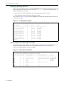
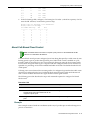
Factory Default Settings ................................................................................................................................. 1-2
Using the Command Line Interface ................................................................................................................ 1-5
Starting a CLI Session ............................................................................................................................. 1-5
Logging In ................................................................................................................................................ 1-6
Navigating the Command Line Interface .................................................................................................. 1-6
Chapter 2: Configuring Switches in a Stack
About SecureStack B2 Switch Operation in a Stack ...................................................................................... 2-1
Installing a New Stackable System of Up to Eight Units ................................................................................ 2-2
Installing Previously-Configured Systems in a Stack ..................................................................................... 2-3
Adding a New Unit to an Existing Stack ......................................................................................................... 2-3
Creating a Virtual Switch Configuration .......................................................................................................... 2-3
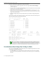
Considerations About Using Clear Config in a Stack ..................................................................................... 2-4
Issues Related to Mixed Type Stacks ............................................................................................................ 2-5
Feature Support ....................................................................................................................................... 2-5
Configuration ............................................................................................................................................ 2-5
Stacking Configuration and Management Commands ................................................................................... 2-5
Purpose .................................................................................................................................................... 2-5
Commands ............................................................................................................................................... 2-5
show switch ........................................................................................................................................ 2-6
show switch switchtype ...................................................................................................................... 2-7
show switch stack-ports...................................................................................................................... 2-8
set switch ............................................................................................................................................ 2-9
set switch copy-fw .............................................................................................................................. 2-9
set switch description ....................................................................................................................... 2-10
set switch movemanagement ........................................................................................................... 2-10
set switch member............................................................................................................................ 2-11
clear switch member......................................................................................................................... 2-11
Chapter 3: Basic Configuration
Quick Start Setup Commands ........................................................................................................................ 3-1
Setting User Accounts and Passwords .......................................................................................................... 3-2
Purpose .................................................................................................................................................... 3-2
Commands ............................................................................................................................................... 3-2
show system login .............................................................................................................................. 3-3
set system login .................................................................................................................................. 3-4
clear system login ............................................................................................................................... 3-4
set password ...................................................................................................................................... 3-5
set system password length ............................................................................................................... 3-6
set system password aging ................................................................................................................3-6
v
set system password history .............................................................................................................. 3-7
show system lockout .......................................................................................................................... 3-7
set system lockout .............................................................................................................................. 3-8
Setting Basic Switch Properties ...................................................................................................................... 3-9
Purpose .................................................................................................................................................... 3-9
Commands ............................................................................................................................................... 3-9
show ip address................................................................................................................................ 3-10
set ip address ................................................................................................................................... 3-11
clear ip address ................................................................................................................................ 3-11
show ip protocol................................................................................................................................ 3-12
set ip protocol ................................................................................................................................... 3-12
show system..................................................................................................................................... 3-13
show system hardware..................................................................................................................... 3-14
show system utilization..................................................................................................................... 3-15
show system enhancedbuffermode .................................................................................................. 3-16
set system enhancedbuffermode ..................................................................................................... 3-16
set system temperature .................................................................................................................... 3-17
clear system temperature ................................................................................................................. 3-18
show time ......................................................................................................................................... 3-19
set time ............................................................................................................................................. 3-19
show summertime ............................................................................................................................ 3-20
set summertime ................................................................................................................................ 3-20
set summertime date ........................................................................................................................ 3-21
set summertime recurring ................................................................................................................. 3-21
clear summertime ............................................................................................................................. 3-22
set prompt......................................................................................................................................... 3-23
show banner motd ............................................................................................................................ 3-23
set banner motd................................................................................................................................ 3-24
clear banner motd............................................................................................................................. 3-24
show version..................................................................................................................................... 3-25
set system name .............................................................................................................................. 3-26
set system location ........................................................................................................................... 3-26
set system contact............................................................................................................................ 3-27
set width ........................................................................................................................................... 3-27
set length .......................................................................................................................................... 3-28
show logout ...................................................................................................................................... 3-28
set logout ......................................................................................................................................... 3-29
show console .................................................................................................................................... 3-29
set console baud .............................................................................................................................. 3-30
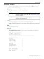
Downloading a Firmware Image ................................................................................................................... 3-30
Downloading from a TFTP Server .......................................................................................................... 3-31
Downloading via the Serial Port ............................................................................................................. 3-31
Reverting to a Previous Image ............................................................................................................... 3-33
Reviewing and Selecting a Boot Firmware Image ........................................................................................ 3-33
Purpose .................................................................................................................................................. 3-33
Commands ............................................................................................................................................. 3-33
show boot system ............................................................................................................................. 3-34
set boot system ................................................................................................................................ 3-34
Starting and Configuring Telnet .................................................................................................................... 3-35
Purpose .................................................................................................................................................. 3-35
Commands ............................................................................................................................................. 3-35
show telnet ....................................................................................................................................... 3-36
set telnet ........................................................................................................................................... 3-36
telnet................................................................................................................................................. 3-37
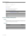
Managing Switch Configuration and Files .................................................................................................... 3-37
Configuration Persistence Mode ............................................................................................................ 3-37
vi
Purpose .................................................................................................................................................. 3-38
Commands ............................................................................................................................................. 3-38
show snmp persistmode ................................................................................................................... 3-38
set snmp persistmode ...................................................................................................................... 3-39
save config ....................................................................................................................................... 3-39
dir...................................................................................................................................................... 3-40
show file............................................................................................................................................ 3-41
show config....................................................................................................................................... 3-41
configure ........................................................................................................................................... 3-42
copy .................................................................................................................................................. 3-43
delete................................................................................................................................................ 3-44
show tftp settings.............................................................................................................................. 3-44
set tftp timeout .................................................................................................................................. 3-45
clear tftp timeout ............................................................................................................................... 3-45
set tftp retry....................................................................................................................................... 3-46
clear tftp retry.................................................................................................................................... 3-46
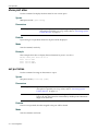
Clearing and Closing the CLI ........................................................................................................................ 3-47
Purpose .................................................................................................................................................. 3-47
Commands ............................................................................................................................................. 3-47
cls (clear screen) .............................................................................................................................. 3-47
exit .................................................................................................................................................... 3-47
Resetting the Switch ..................................................................................................................................... 3-48
Purpose .................................................................................................................................................. 3-48
Commands ............................................................................................................................................. 3-48
reset.................................................................................................................................................. 3-48
clear config ....................................................................................................................................... 3-49
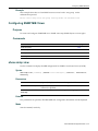
Using and Configuring WebView .................................................................................................................. 3-50
Purpose .................................................................................................................................................. 3-50
Commands ............................................................................................................................................. 3-50
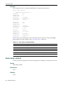
show webview .................................................................................................................................. 3-50
set webview ...................................................................................................................................... 3-51
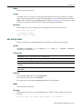
show ssl............................................................................................................................................ 3-51
set ssl ............................................................................................................................................... 3-52
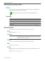
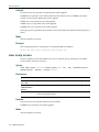
Gathering Technical Support Information ..................................................................................................... 3-52
Purpose .................................................................................................................................................. 3-52
Command ............................................................................................................................................... 3-52
show support .................................................................................................................................... 3-53
Chapter 4: Activating Licensed Features
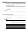
License Key Field Descriptions ...................................................................................................................... 4-1
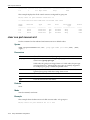
Licensing Procedure in a Stack Environment ................................................................................................. 4-1
Adding a New Member to a Licensed Stack ............................................................................................ 4-2
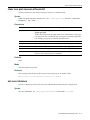
Clearing, Showing, and Applying Licenses .................................................................................................... 4-2
Commands ............................................................................................................................................... 4-2
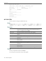
set license........................................................................................................................................... 4-3
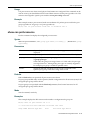
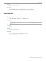
show license ....................................................................................................................................... 4-4
clear license........................................................................................................................................ 4-4
Chapter 5: Configuring System Power and PoE
Commands ..................................................................................................................................................... 5-1
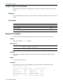
show inlinepower ................................................................................................................................ 5-1
set inlinepower threshold.................................................................................................................... 5-2
set inlinepower trap ............................................................................................................................ 5-3
set inlinepower detectionmode ........................................................................................................... 5-3
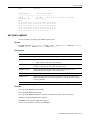
show port inlinepower ......................................................................................................................... 5-4
vii
set port inlinepower ............................................................................................................................ 5-5
Chapter 6: Discovery Protocol Configuration
Configuring CDP ............................................................................................................................................. 6-1
Purpose .................................................................................................................................................... 6-1
Commands ............................................................................................................................................... 6-1
show cdp ............................................................................................................................................ 6-2
set cdp state ....................................................................................................................................... 6-3
set cdp auth ........................................................................................................................................ 6-4
set cdp interval ................................................................................................................................... 6-4
set cdp hold-time ................................................................................................................................ 6-5
clear cdp ............................................................................................................................................. 6-5
show neighbors .................................................................................................................................. 6-6
Configuring Cisco Discovery Protocol ............................................................................................................ 6-7
Purpose .................................................................................................................................................... 6-7
Commands ............................................................................................................................................... 6-7
show ciscodp ...................................................................................................................................... 6-7
show ciscodp port info ........................................................................................................................ 6-8
set ciscodp status ............................................................................................................................... 6-9
set ciscodp timer................................................................................................................................. 6-9
set ciscodp holdtime ......................................................................................................................... 6-10
set ciscodp port ................................................................................................................................ 6-10
clear ciscodp..................................................................................................................................... 6-12
Configuring Link Layer Discovery Protocol and LLDP-MED ........................................................................ 6-13
Overview ................................................................................................................................................ 6-13
Purpose .................................................................................................................................................. 6-13
Commands ............................................................................................................................................. 6-13
Configuration Tasks ............................................................................................................................... 6-14
show lldp........................................................................................................................................... 6-14
show lldp port status......................................................................................................................... 6-15
show lldp port trap ............................................................................................................................ 6-16
show lldp port tx-tlv........................................................................................................................... 6-16
show lldp port location-info ............................................................................................................... 6-17
show lldp port local-info .................................................................................................................... 6-18
show lldp port remote-info ................................................................................................................ 6-20
set lldp tx-interval.............................................................................................................................. 6-22
set lldp hold-multiplier ....................................................................................................................... 6-22
set lldp trap-interval .......................................................................................................................... 6-23
set lldp med-fast-repeat .................................................................................................................... 6-23
set lldp port status ............................................................................................................................ 6-24
set lldp port trap................................................................................................................................ 6-24
set lldp port med-trap........................................................................................................................ 6-25
set lldp port tx-tlv .............................................................................................................................. 6-25
clear lldp ........................................................................................................................................... 6-27
clear lldp port status ......................................................................................................................... 6-27
clear lldp port trap ............................................................................................................................. 6-28
clear lldp port med-trap..................................................................................................................... 6-28
clear lldp port tx-tlv ........................................................................................................................... 6-29
Chapter 7: Port Configuration
Port Configuration Summary .......................................................................................................................... 7-1
B2H124-48 and B2H124-48P Switch Ports ............................................................................................. 7-1
B2G124-24, B2G124-48, and B2G124-48P Switch Ports ........................................................................ 7-1
Port String Syntax Used in the CLI .......................................................................................................... 7-2
viii
Reviewing Port Status .................................................................................................................................... 7-3
Purpose .................................................................................................................................................... 7-3
Commands ............................................................................................................................................... 7-3
show port ............................................................................................................................................ 7-3
show port status ................................................................................................................................. 7-4
show port counters ............................................................................................................................. 7-5
Disabling / Enabling and Naming Ports .......................................................................................................... 7-6
Purpose .................................................................................................................................................... 7-6
Commands ............................................................................................................................................... 7-6
set port disable ................................................................................................................................... 7-7
set port enable.................................................................................................................................... 7-7
show port alias.................................................................................................................................... 7-8
set port alias ....................................................................................................................................... 7-8
Setting Speed and Duplex Mode .................................................................................................................. 7-10
Purpose .................................................................................................................................................. 7-10
Commands ............................................................................................................................................. 7-10
show port speed ............................................................................................................................... 7-10
set port speed................................................................................................................................... 7-11
show port duplex .............................................................................................................................. 7-11
set port duplex .................................................................................................................................. 7-12
Enabling / Disabling Jumbo Frame Support ................................................................................................. 7-13
Purpose .................................................................................................................................................. 7-13
Commands ............................................................................................................................................. 7-13
show port jumbo ............................................................................................................................... 7-13
set port jumbo................................................................................................................................... 7-14
clear port jumbo ................................................................................................................................ 7-14
Setting Auto-Negotiation and Advertised Ability ........................................................................................... 7-15
Purpose .................................................................................................................................................. 7-15
Commands ............................................................................................................................................. 7-15
show port negotiation ....................................................................................................................... 7-15
set port negotiation ........................................................................................................................... 7-16
show port advertise .......................................................................................................................... 7-16
set port advertise .............................................................................................................................. 7-17
clear port advertise ........................................................................................................................... 7-18
Setting Flow Control ..................................................................................................................................... 7-19
Purpose .................................................................................................................................................. 7-19
Commands ............................................................................................................................................. 7-19
show flowcontrol ............................................................................................................................... 7-19
set flowcontrol................................................................................................................................... 7-19
Setting Port Link Traps and Link Flap Detection .......................................................................................... 7-21
Purpose .................................................................................................................................................. 7-21
Commands ............................................................................................................................................. 7-21
show port trap................................................................................................................................... 7-21
set port trap ...................................................................................................................................... 7-22
show linkflap ..................................................................................................................................... 7-22
set linkflap globalstate ...................................................................................................................... 7-25
set linkflap portstate.......................................................................................................................... 7-25
set linkflap interval ............................................................................................................................ 7-26
set linkflap action .............................................................................................................................. 7-26
clear linkflap action ........................................................................................................................... 7-27
set linkflap threshold......................................................................................................................... 7-27
set linkflap downtime ........................................................................................................................ 7-28
clear linkflap down ............................................................................................................................ 7-28
clear linkflap...................................................................................................................................... 7-29
Configuring Broadcast Suppression ............................................................................................................. 7-30
Purpose .................................................................................................................................................. 7-30
ix
Commands ............................................................................................................................................. 7-30
show port broadcast ......................................................................................................................... 7-30
set port broadcast............................................................................................................................. 7-31
clear port broadcast.......................................................................................................................... 7-31
Port Mirroring ................................................................................................................................................ 7-33
Mirroring Features .................................................................................................................................. 7-33
Configuring SMON MIB Port Mirroring ................................................................................................... 7-33
Purpose .................................................................................................................................................. 7-34
Commands ............................................................................................................................................. 7-34
show port mirroring........................................................................................................................... 7-35
set port mirroring .............................................................................................................................. 7-35
clear port mirroring ........................................................................................................................... 7-36
Link Aggregation Control Protocol (LACP) ................................................................................................... 7-38
LACP Operation ..................................................................................................................................... 7-38
LACP Terminology ................................................................................................................................. 7-39
SecureStack B2 Usage Considerations ................................................................................................. 7-39
Commands ............................................................................................................................................. 7-40
show lacp.......................................................................................................................................... 7-41
set lacp ............................................................................................................................................. 7-42
set lacp asyspri................................................................................................................................. 7-43
set lacp aadminkey........................................................................................................................... 7-43
clear lacp .......................................................................................................................................... 7-44
set lacp static.................................................................................................................................... 7-44
clear lacp static ................................................................................................................................. 7-45
set lacp singleportlag........................................................................................................................ 7-46
clear lacp singleportlag..................................................................................................................... 7-46
show port lacp .................................................................................................................................. 7-47
set port lacp ...................................................................................................................................... 7-48
clear port lacp ................................................................................................................................... 7-50
Configuring Protected Ports ......................................................................................................................... 7-52
Protected Port Operation ....................................................................................................................... 7-52
Commands ............................................................................................................................................. 7-52
set port protected.............................................................................................................................. 7-52
show port protected .......................................................................................................................... 7-53
clear port protected........................................................................................................................... 7-53
set port protected name.................................................................................................................... 7-54
show port protected name ................................................................................................................ 7-54
clear port protected name................................................................................................................. 7-55
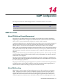
Chapter 8: SNMP Configuration
SNMP Configuration Summary ...................................................................................................................... 8-1
SNMPv1 and SNMPv2c ........................................................................................................................... 8-1
SNMPv3 ................................................................................................................................................... 8-2
About SNMP Security Models and Levels ............................................................................................... 8-2
Using SNMP Contexts to Access Specific MIBs ...................................................................................... 8-3
Configuration Considerations ................................................................................................................... 8-3
Reviewing SNMP Statistics ............................................................................................................................ 8-3
Purpose .................................................................................................................................................... 8-3
Commands ............................................................................................................................................... 8-4
show snmp engineid........................................................................................................................... 8-4
show snmp counters........................................................................................................................... 8-5
Configuring SNMP Users, Groups, and Communities .................................................................................... 8-8
Purpose .................................................................................................................................................... 8-8
Commands ............................................................................................................................................... 8-8
show snmp user ................................................................................................................................. 8-8
x
set snmp user ..................................................................................................................................... 8-9
clear snmp user ................................................................................................................................ 8-10
show snmp group ............................................................................................................................. 8-11
set snmp group ................................................................................................................................. 8-12
clear snmp group .............................................................................................................................. 8-12
show snmp community ..................................................................................................................... 8-13
set snmp community......................................................................................................................... 8-14
clear snmp community...................................................................................................................... 8-14
Configuring SNMP Access Rights ................................................................................................................ 8-15
Purpose .................................................................................................................................................. 8-15
Commands ............................................................................................................................................. 8-15
show snmp access ........................................................................................................................... 8-15
set snmp access............................................................................................................................... 8-17
clear snmp access............................................................................................................................ 8-18
Configuring SNMP MIB Views ...................................................................................................................... 8-19
Purpose .................................................................................................................................................. 8-19
Commands ............................................................................................................................................. 8-19
show snmp view ............................................................................................................................... 8-19
show snmp context........................................................................................................................... 8-20
set snmp view................................................................................................................................... 8-21
clear snmp view................................................................................................................................ 8-22
Configuring SNMP Target Parameters ......................................................................................................... 8-22
Purpose .................................................................................................................................................. 8-22
Commands ............................................................................................................................................. 8-22
show snmp targetparams ................................................................................................................. 8-22
set snmp targetparams..................................................................................................................... 8-24
clear snmp targetparams.................................................................................................................. 8-24
Configuring SNMP Target Addresses .......................................................................................................... 8-25
Purpose .................................................................................................................................................. 8-25
Commands ............................................................................................................................................. 8-25
show snmp targetaddr ...................................................................................................................... 8-25
set snmp targetaddr.......................................................................................................................... 8-26
clear snmp targetaddr....................................................................................................................... 8-28
Configuring SNMP Notification Parameters ................................................................................................. 8-28
About SNMP Notify Filters ..................................................................................................................... 8-28
Purpose .................................................................................................................................................. 8-28
Commands ............................................................................................................................................. 8-29
show newaddrtrap ............................................................................................................................ 8-29
set newaddrtrap................................................................................................................................ 8-30
show snmp notify .............................................................................................................................. 8-30
set snmp notify ................................................................................................................................. 8-31
clear snmp notify .............................................................................................................................. 8-32
show snmp notifyfilter ....................................................................................................................... 8-33
set snmp notifyfilter........................................................................................................................... 8-34
clear snmp notifyfilter........................................................................................................................ 8-34
show snmp notifyprofile .................................................................................................................... 8-35
set snmp notifyprofile........................................................................................................................ 8-36
clear snmp notifyprofile..................................................................................................................... 8-36
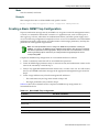
Creating a Basic SNMP Trap Configuration ................................................................................................. 8-37
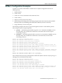
Example ................................................................................................................................................. 8-38
Chapter 9: Spanning Tree Configuration
Spanning Tree Configuration Summary ......................................................................................................... 9-1
Overview: Single, Rapid, and Multiple Spanning Tree Protocols ............................................................. 9-1
Spanning Tree Features .......................................................................................................................... 9-2
xi
Loop Protect ............................................................................................................................................. 9-2
Configuring Spanning Tree Bridge Parameters .............................................................................................. 9-3
Purpose .................................................................................................................................................... 9-3
Commands ............................................................................................................................................... 9-4
show spantree stats............................................................................................................................ 9-5
set spantree........................................................................................................................................ 9-7
show spantree version........................................................................................................................ 9-7
set spantree version ........................................................................................................................... 9-8
clear spantree version ........................................................................................................................ 9-8
show spantree bpdu-forwarding ......................................................................................................... 9-9
set spantree bpdu-forwarding............................................................................................................. 9-9
show spantree bridgeprioritymode ................................................................................................... 9-10
set spantree bridgeprioritymode ....................................................................................................... 9-10
clear spantree bridgeprioritymode .................................................................................................... 9-11
show spantree mstilist ...................................................................................................................... 9-12
set spantree msti .............................................................................................................................. 9-12
clear spantree msti ........................................................................................................................... 9-13
show spantree mstmap .................................................................................................................... 9-13
set spantree mstmap ........................................................................................................................ 9-14
clear spantree mstmap ..................................................................................................................... 9-14
show spantree vlanlist ...................................................................................................................... 9-15
show spantree mstcfgid .................................................................................................................... 9-15
set spantree mstcfgid ....................................................................................................................... 9-16
clear spantree mstcfgid .................................................................................................................... 9-16
set spantree priority .......................................................................................................................... 9-17
clear spantree priority ....................................................................................................................... 9-17
set spantree hello ............................................................................................................................. 9-18
clear spantree hello .......................................................................................................................... 9-18
set spantree maxage ........................................................................................................................ 9-19
clear spantree maxage ..................................................................................................................... 9-19
set spantree fwddelay....................................................................................................................... 9-20
clear spantree fwddelay.................................................................................................................... 9-21
show spantree backuproot ............................................................................................................... 9-21
set spantree backuproot ................................................................................................................... 9-22
clear spantree backuproot ................................................................................................................ 9-22
show spantree tctrapsuppress.......................................................................................................... 9-23
set spantree tctrapsuppress ............................................................................................................. 9-23
clear spantree tctrapsuppress .......................................................................................................... 9-24
set spantree protomigration .............................................................................................................. 9-24
show spantree spanguard ................................................................................................................ 9-25
set spantree spanguard .................................................................................................................... 9-25
clear spantree spanguard ................................................................................................................. 9-26
show spantree spanguardtimeout .................................................................................................... 9-27
set spantree spanguardtimeout ........................................................................................................ 9-27
clear spantree spanguardtimeout ..................................................................................................... 9-28
show spantree spanguardlock .......................................................................................................... 9-28
clear / set spantree spanguardlock................................................................................................... 9-29
show spantree spanguardtrapenable ............................................................................................... 9-29
set spantree spanguardtrapenable ................................................................................................... 9-30
clear spantree spanguardtrapenable ................................................................................................ 9-30
show spantree legacypathcost ......................................................................................................... 9-31
set spantree legacypathcost............................................................................................................. 9-31
clear spantree legacypathcost .......................................................................................................... 9-32
Configuring Spanning Tree Port Parameters ............................................................................................... 9-33
Purpose .................................................................................................................................................. 9-33
Commands ............................................................................................................................................. 9-33
xii
set spantree portadmin..................................................................................................................... 9-33
clear spantree portadmin.................................................................................................................. 9-34
show spantree portadmin ................................................................................................................. 9-34
show spantree portpri ....................................................................................................................... 9-35
set spantree portpri........................................................................................................................... 9-35
clear spantree portpri........................................................................................................................ 9-36
show spantree adminpathcost .......................................................................................................... 9-37
set spantree adminpathcost ............................................................................................................. 9-37
clear spantree adminpathcost .......................................................................................................... 9-38
show spantree adminedge ............................................................................................................... 9-38
set spantree adminedge ................................................................................................................... 9-39
clear spantree adminedge ................................................................................................................ 9-39
Configuring Spanning Tree Loop Protect Parameters .................................................................................. 9-41
Purpose .................................................................................................................................................. 9-41
Commands ............................................................................................................................................. 9-41
set spantree lp .................................................................................................................................. 9-42
show spantree lp .............................................................................................................................. 9-42
clear spantree lp ............................................................................................................................... 9-43
show spantree lplock ........................................................................................................................ 9-43
clear spantree lplock......................................................................................................................... 9-44
set spantree lpcapablepartner .......................................................................................................... 9-45
show spantree lpcapablepartner ...................................................................................................... 9-45
clear spantree lpcapablepartner ....................................................................................................... 9-46
set spantree lpthreshold ................................................................................................................... 9-46
show spantree lpthreshold................................................................................................................ 9-47
clear spantree lpthreshold ................................................................................................................ 9-47
set spantree lpwindow ...................................................................................................................... 9-48
show spantree lpwindow .................................................................................................................. 9-48
clear spantree lpwindow ................................................................................................................... 9-49
set spantree lptrapenable ................................................................................................................. 9-49
show spantree lptrapenable ............................................................................................................. 9-50
clear spantree lptrapenable .............................................................................................................. 9-50
set spantree disputedbpduthreshold ................................................................................................ 9-51
show spantree disputedbpduthreshold ............................................................................................. 9-52
clear spantree disputedbpduthreshold ............................................................................................. 9-52
show spantree nonforwardingreason ............................................................................................... 9-53
Chapter 10: 802.1Q VLAN Configuration
VLAN Configuration Summary ..................................................................................................................... 10-1
Port String Syntax Used in the CLI ........................................................................................................ 10-1
Creating a Secure Management VLAN .................................................................................................. 10-1
Viewing VLANs ............................................................................................................................................. 10-2
Purpose .................................................................................................................................................. 10-2
Command ............................................................................................................................................... 10-3
show vlan.......................................................................................................................................... 10-3
Creating and Naming Static VLANs ............................................................................................................. 10-5
Purpose .................................................................................................................................................. 10-5
Commands ............................................................................................................................................. 10-5
set vlan ............................................................................................................................................. 10-5
set vlan name ................................................................................................................................... 10-6
clear vlan .......................................................................................................................................... 10-6
clear vlan name ................................................................................................................................ 10-7
Assigning Port VLAN IDs (PVIDs) and Ingress Filtering .............................................................................. 10-8
Purpose .................................................................................................................................................. 10-8
Commands ............................................................................................................................................. 10-8
xiii
show port vlan .................................................................................................................................. 10-8
set port vlan ...................................................................................................................................... 10-9
clear port vlan ................................................................................................................................... 10-9
show port ingress filter.................................................................................................................... 10-10
set port ingress filter ....................................................................................................................... 10-11
show port discard ........................................................................................................................... 10-11
set port discard ............................................................................................................................... 10-12
Configuring the VLAN Egress List .............................................................................................................. 10-13
Purpose ................................................................................................................................................ 10-13
Commands ........................................................................................................................................... 10-13
show port egress ............................................................................................................................ 10-13
set vlan forbidden ........................................................................................................................... 10-14
set vlan egress ............................................................................................................................... 10-15
clear vlan egress ............................................................................................................................ 10-15
show vlan dynamicegress .............................................................................................................. 10-16
set vlan dynamicegress .................................................................................................................. 10-17
Setting the Host VLAN ................................................................................................................................ 10-18
Purpose ................................................................................................................................................ 10-18
Commands ........................................................................................................................................... 10-18
show host vlan................................................................................................................................ 10-18
set host vlan ................................................................................................................................... 10-18
clear host vlan ................................................................................................................................ 10-19
Enabling/Disabling GVRP (GARP VLAN Registration Protocol) ................................................................ 10-20
About GARP VLAN Registration Protocol (GVRP) .............................................................................. 10-20
Purpose ................................................................................................................................................ 10-21
Commands ........................................................................................................................................... 10-21
show gvrp ....................................................................................................................................... 10-22
show garp timer .............................................................................................................................. 10-22
set gvrp........................................................................................................................................... 10-23
clear gvrp ........................................................................................................................................ 10-24
set garp timer.................................................................................................................................. 10-24
Chapter 11: Differentiated Services Configuration
Globally Enabling or Disabling Diffserv ........................................................................................................ 11-2
Purpose .................................................................................................................................................. 11-2
Command ............................................................................................................................................... 11-2
set diffserv adminmode .................................................................................................................... 11-2
Creating Diffserv Classes and Matching Conditions .................................................................................... 11-3
Purpose .................................................................................................................................................. 11-3
Commands ............................................................................................................................................. 11-3
show diffserv info .............................................................................................................................. 11-3
show diffserv class ........................................................................................................................... 11-4
set class create................................................................................................................................. 11-4
set diffserv class delete .................................................................................................................... 11-5
set diffserv class match .................................................................................................................... 11-5
set diffserv class rename .................................................................................................................. 11-8
Configuring Diffserv Policies and Assigning Classes ................................................................................... 11-9
Purpose .................................................................................................................................................. 11-9
Commands ............................................................................................................................................. 11-9
show diffserv policy .......................................................................................................................... 11-9
set diffserv policy create ................................................................................................................. 11-10
set diffserv policy delete ................................................................................................................. 11-10
set diffserv policy class................................................................................................................... 11-11
set diffserv policy mark ................................................................................................................... 11-11
set diffserv policy police style simple .............................................................................................. 11-12
xiv
set diffserv policy police action conform ......................................................................................... 11-13
set diffserv policy police action nonconform ...................................................................................11-13
set diffserv policy rename ............................................................................................................... 11-14
Assigning Policies to Service Ports ............................................................................................................ 11-14
Purpose ................................................................................................................................................ 11-14
Commands ........................................................................................................................................... 11-15
show diffserv service info ............................................................................................................... 11-15
show diffserv service stats.............................................................................................................. 11-15
set diffserv service.......................................................................................................................... 11-16
DiffServ Configuration Examples ................................................................................................................ 11-17
Chapter 12: Policy Classification Configuration
Policy Classification Configuration Summary ............................................................................................... 12-1
Configuring Policy Profiles ............................................................................................................................ 12-1
Purpose .................................................................................................................................................. 12-1
Commands ............................................................................................................................................. 12-2
show policy profile ............................................................................................................................ 12-2
set policy profile ................................................................................................................................ 12-3
clear policy profile ............................................................................................................................. 12-4
Configuring Classification Rules ................................................................................................................... 12-6
Purpose .................................................................................................................................................. 12-6
Commands ............................................................................................................................................. 12-6
show policy rule ................................................................................................................................ 12-6
show policy capability ....................................................................................................................... 12-8
set policy rule.................................................................................................................................. 12-10
clear policy rule............................................................................................................................... 12-13
clear policy all-rules ........................................................................................................................ 12-14
Assigning Ports to Policy Profiles ............................................................................................................... 12-15
Purpose ................................................................................................................................................ 12-15
Commands ........................................................................................................................................... 12-15
set policy port ................................................................................................................................. 12-15
clear policy port .............................................................................................................................. 12-16
Configuring Policy Class of Service (CoS) ................................................................................................. 12-17
About Policy-Based CoS Configurations .............................................................................................. 12-17
About CoS-Based Flood Control .......................................................................................................... 12-19
Commands ........................................................................................................................................... 12-20
set cos state ................................................................................................................................... 12-20
show cos state................................................................................................................................ 12-21
clear cos state ................................................................................................................................ 12-21
set cos settings............................................................................................................................... 12-22
clear cos settings ............................................................................................................................ 12-23
show cos settings ........................................................................................................................... 12-23
set cos port-config .......................................................................................................................... 12-24
show cos port-config....................................................................................................................... 12-25
clear cos port-config ....................................................................................................................... 12-26
set cos port-resource irl .................................................................................................................. 12-27
set cos port-resource flood-ctrl ....................................................................................................... 12-28
show cos port-resource .................................................................................................................. 12-29
clear cos port-resource irl ............................................................................................................... 12-30
clear cos port-resource flood-ctrl .................................................................................................... 12-31
set cos reference ............................................................................................................................ 12-31
show cos reference ........................................................................................................................ 12-32
clear cos reference ......................................................................................................................... 12-33
show cos unit.................................................................................................................................. 12-34
clear cos all-entries......................................................................................................................... 12-35
xv
show cos port-type ......................................................................................................................... 12-35
Chapter 13: Port Priority and Rate Limiting Configuration
Port Priority Configuration Summary ............................................................................................................ 13-1
Configuring Port Priority ............................................................................................................................... 13-1
Purpose .................................................................................................................................................. 13-1
Commands ............................................................................................................................................. 13-2
show port priority .............................................................................................................................. 13-2
set port priority.................................................................................................................................. 13-2
clear port priority............................................................................................................................... 13-3
Configuring Priority to Transmit Queue Mapping ......................................................................................... 13-4
Purpose .................................................................................................................................................. 13-4
Commands ............................................................................................................................................. 13-4
show port priority-queue ................................................................................................................... 13-4
set port priority-queue....................................................................................................................... 13-5
clear port priority-queue.................................................................................................................... 13-6
Configuring Quality of Service (QoS) ........................................................................................................... 13-6
Purpose .................................................................................................................................................. 13-6
Commands ............................................................................................................................................. 13-6
show port txq .................................................................................................................................... 13-6
set port txq........................................................................................................................................ 13-7
clear port txq..................................................................................................................................... 13-8
Configuring Port Traffic Rate Limiting ......................................................................................................... 13-10
Purpose ................................................................................................................................................ 13-10
Commands ........................................................................................................................................... 13-10
show port ratelimit .......................................................................................................................... 13-10
set port ratelimit .............................................................................................................................. 13-12
clear port ratelimit ........................................................................................................................... 13-13
Chapter 14: IGMP Configuration
IGMP Overview ............................................................................................................................................ 14-1
About IP Multicast Group Management ................................................................................................. 14-1
About Multicasting .................................................................................................................................. 14-1
Configuring IGMP at Layer 2 ........................................................................................................................ 14-2
Purpose .................................................................................................................................................. 14-2
Commands ............................................................................................................................................. 14-2
show igmpsnooping .......................................................................................................................... 14-2
set igmpsnooping adminmode.......................................................................................................... 14-3
set igmpsnooping interfacemode...................................................................................................... 14-3
set igmpsnooping groupmembershipinterval .................................................................................... 14-4
set igmpsnooping maxresponse ....................................................................................................... 14-5
set igmpsnooping mcrtrexpiretime.................................................................................................... 14-5
set igmpsnooping add-static ............................................................................................................. 14-6
set igmpsnooping remove-static ....................................................................................................... 14-7
show igmpsnooping static ................................................................................................................ 14-7
show igmpsnooping mfdb ................................................................................................................. 14-8
clear igmpsnooping .......................................................................................................................... 14-8
Chapter 15: Logging and Network Management
Configuring System Logging ........................................................................................................................ 15-1
Purpose .................................................................................................................................................. 15-1
Commands ............................................................................................................................................. 15-1
show logging server.......................................................................................................................... 15-2
set logging server ............................................................................................................................. 15-3
clear logging server .......................................................................................................................... 15-4
xvi
show logging default......................................................................................................................... 15-4
set logging default ............................................................................................................................ 15-5
clear logging default ......................................................................................................................... 15-6
show logging application .................................................................................................................. 15-6
set logging application ...................................................................................................................... 15-7
clear logging application ................................................................................................................... 15-8
show logging local ............................................................................................................................ 15-9
set logging local................................................................................................................................ 15-9
clear logging local........................................................................................................................... 15-10
show logging buffer ........................................................................................................................ 15-10
Monitoring Network Events and Status ...................................................................................................... 15-12
Purpose ................................................................................................................................................ 15-12
Commands ........................................................................................................................................... 15-12
history ............................................................................................................................................. 15-12
show history.................................................................................................................................... 15-13
set history ....................................................................................................................................... 15-13
ping................................................................................................................................................. 15-14
show users ..................................................................................................................................... 15-14
disconnect ...................................................................................................................................... 15-15
show netstat ................................................................................................................................... 15-15
Managing Switch Network Addresses and Routes ..................................................................................... 15-17
Purpose ................................................................................................................................................ 15-17
Commands ........................................................................................................................................... 15-17
show arp ......................................................................................................................................... 15-17
set arp............................................................................................................................................. 15-18
clear arp.......................................................................................................................................... 15-19
traceroute ....................................................................................................................................... 15-19
show mac ....................................................................................................................................... 15-20
show mac agetime.......................................................................................................................... 15-21
set mac agetime ............................................................................................................................. 15-22
clear mac agetime .......................................................................................................................... 15-22
set mac algorithm ........................................................................................................................... 15-23
show mac algorithm........................................................................................................................ 15-23
clear mac algorithm ........................................................................................................................ 15-24
set mac multicast ............................................................................................................................ 15-24
clear mac address .......................................................................................................................... 15-25
show mac unreserved-flood ........................................................................................................... 15-26
set mac unreserved-flood ............................................................................................................... 15-26
Configuring Simple Network Time Protocol (SNTP) ................................................................................... 15-27
Purpose ................................................................................................................................................ 15-27
Commands ........................................................................................................................................... 15-27
show sntp ....................................................................................................................................... 15-27
set sntp client.................................................................................................................................. 15-29
clear sntp client............................................................................................................................... 15-29
set sntp server ................................................................................................................................ 15-30
clear sntp server ............................................................................................................................. 15-30
set sntp poll-interval........................................................................................................................ 15-31
clear sntp poll-interval..................................................................................................................... 15-31
set sntp poll-retry ............................................................................................................................ 15-32
clear sntp poll-retry ......................................................................................................................... 15-32
set sntp poll-timeout ....................................................................................................................... 15-33
clear sntp poll-timeout .................................................................................................................... 15-33
set timezone ................................................................................................................................... 15-33
Configuring Node Aliases ........................................................................................................................... 15-35
Purpose ................................................................................................................................................ 15-35
Commands ........................................................................................................................................... 15-35
xvii
show nodealias config .................................................................................................................... 15-35
set nodealias .................................................................................................................................. 15-36
clear nodealias config ..................................................................................................................... 15-37
Chapter 16: RMON Configuration
RMON Monitoring Group Functions ............................................................................................................. 16-1
Design Considerations ................................................................................................................................. 16-2
Statistics Group Commands ......................................................................................................................... 16-3
Purpose .................................................................................................................................................. 16-3
Commands ............................................................................................................................................. 16-3
show rmon stats ............................................................................................................................... 16-4
set rmon stats ................................................................................................................................... 16-4
clear rmon stats ................................................................................................................................ 16-5
History Group Commands ............................................................................................................................ 16-6
Purpose .................................................................................................................................................. 16-6
Commands ............................................................................................................................................. 16-6
show rmon history ............................................................................................................................ 16-6
set rmon history ................................................................................................................................ 16-7
clear rmon history ............................................................................................................................. 16-7
Alarm Group Commands .............................................................................................................................. 16-9
Purpose .................................................................................................................................................. 16-9
Commands ............................................................................................................................................. 16-9
show rmon alarm .............................................................................................................................. 16-9
set rmon alarm properties............................................................................................................... 16-10
set rmon alarm status ..................................................................................................................... 16-11
clear rmon alarm............................................................................................................................. 16-12
Event Group Commands ............................................................................................................................ 16-13
Purpose ................................................................................................................................................ 16-13
Commands ........................................................................................................................................... 16-13
show rmon event ............................................................................................................................ 16-13
set rmon event properties ............................................................................................................... 16-14
set rmon event status ..................................................................................................................... 16-15
clear rmon event............................................................................................................................. 16-15
Filter Group Commands ............................................................................................................................. 16-17
Commands ........................................................................................................................................... 16-17
show rmon channel ........................................................................................................................ 16-17
set rmon channel ............................................................................................................................ 16-18
clear rmon channel ......................................................................................................................... 16-19
show rmon filter .............................................................................................................................. 16-19
set rmon filter .................................................................................................................................. 16-20
clear rmon filter ............................................................................................................................... 16-21
Packet Capture Commands ....................................................................................................................... 16-22
Purpose ................................................................................................................................................ 16-22
Commands ........................................................................................................................................... 16-22
show rmon capture ......................................................................................................................... 16-22
set rmon capture............................................................................................................................. 16-23
clear rmon capture.......................................................................................................................... 16-24
Chapter 17: DHCP Server Configuration
DHCP Overview ........................................................................................................................................... 17-1
DHCP Server ......................................................................................................................................... 17-1
Configuring a DHCP Server ................................................................................................................... 17-2
Configuring General DHCP Server Parameters ........................................................................................... 17-3
Purpose .................................................................................................................................................. 17-3
Commands ............................................................................................................................................. 17-3
xviii
set dhcp ............................................................................................................................................ 17-3
set dhcp bootp .................................................................................................................................. 17-4
set dhcp conflict logging ................................................................................................................... 17-4
show dhcp conflict ............................................................................................................................ 17-5
clear dhcp conflict............................................................................................................................. 17-5
set dhcp exclude............................................................................................................................... 17-6
clear dhcp exclude............................................................................................................................ 17-7
set dhcp ping .................................................................................................................................... 17-7
clear dhcp ping ................................................................................................................................. 17-8
show dhcp binding............................................................................................................................ 17-8
clear dhcp binding ............................................................................................................................ 17-9
show dhcp server statistics............................................................................................................... 17-9
clear dhcp server statistics ............................................................................................................. 17-10
Configuring IP Address Pools ..................................................................................................................... 17-11
Manual Pool Configuration Considerations .......................................................................................... 17-11
Purpose ................................................................................................................................................ 17-11
Commands ........................................................................................................................................... 17-11
set dhcp pool .................................................................................................................................. 17-12
clear dhcp pool ............................................................................................................................... 17-13
set dhcp pool network..................................................................................................................... 17-13
clear dhcp pool network.................................................................................................................. 17-14
set dhcp pool hardware-address .................................................................................................... 17-14
clear dhcp pool hardware-address ................................................................................................. 17-15
set dhcp pool host .......................................................................................................................... 17-15
clear dhcp pool host ....................................................................................................................... 17-16
set dhcp pool client-identifier .......................................................................................................... 17-16
clear dhcp pool client-identifier ....................................................................................................... 17-17
set dhcp pool client-name............................................................................................................... 17-18
clear dhcp pool client-name............................................................................................................17-18
set dhcp pool bootfile...................................................................................................................... 17-19
clear dhcp pool bootfile................................................................................................................... 17-19
set dhcp pool next-server ............................................................................................................... 17-20
clear dhcp pool next-server ............................................................................................................17-20
set dhcp pool lease......................................................................................................................... 17-21
clear dhcp pool lease...................................................................................................................... 17-21
set dhcp pool default-router ............................................................................................................17-22
clear dhcp pool default-router......................................................................................................... 17-22
set dhcp pool dns-server ................................................................................................................ 17-23
clear dhcp pool dns-server ............................................................................................................. 17-23
set dhcp pool domain-name ........................................................................................................... 17-24
clear dhcp pool domain-name ........................................................................................................ 17-24
set dhcp pool netbios-name-server ................................................................................................ 17-25
clear dhcp pool netbios-name-server ............................................................................................. 17-25
set dhcp pool netbios-node-type .................................................................................................... 17-26
clear dhcp pool netbios-node-type ................................................................................................. 17-26
set dhcp pool option ....................................................................................................................... 17-27
clear dhcp pool option .................................................................................................................... 17-28
show dhcp pool configuration ......................................................................................................... 17-28
Chapter 18: DHCP Snooping and Dynamic ARP Inspection
DHCP Snooping Overview ........................................................................................................................... 18-1
DHCP Message Processing ................................................................................................................... 18-1
Building and Maintaining the Database .................................................................................................. 18-2
Rate Limiting .......................................................................................................................................... 18-3
Basic Configuration ................................................................................................................................ 18-3
xix
DHCP Snooping Commands ........................................................................................................................ 18-4
set dhcpsnooping ............................................................................................................................. 18-5
set dhcpsnooping vlan...................................................................................................................... 18-5
set dhcpsnooping database write-delay ........................................................................................... 18-6
set dhcpsnooping trust ..................................................................................................................... 18-6
set dhcpsnooping binding ................................................................................................................. 18-7
set dhcpsnooping verify .................................................................................................................... 18-8
set dhcpsnooping log-invalid ............................................................................................................ 18-9
set dhcpsnooping limit .................................................................................................................... 18-10
show dhcpsnooping ........................................................................................................................ 18-11
show dhcpsnooping database ........................................................................................................ 18-11
show dhcpsnooping port................................................................................................................. 18-12
show dhcpsnooping binding ........................................................................................................... 18-13
show dhcpsnooping statistics ......................................................................................................... 18-13
clear dhcpsnooping binding ............................................................................................................18-14
clear dhcpsnooping statistics.......................................................................................................... 18-15
clear dhcpsnooping database......................................................................................................... 18-15
clear dhcpsnooping limit ................................................................................................................. 18-16
Dynamic ARP Inspection Overview ............................................................................................................ 18-16
Functional Description .......................................................................................................................... 18-16
Basic Configuration .............................................................................................................................. 18-18
Example Configuration ......................................................................................................................... 18-19
Dynamic ARP Inspection Commands ........................................................................................................ 18-20
set arpinspection vlan ..................................................................................................................... 18-20
set arpinspection trust .................................................................................................................... 18-21
set arpinspection validate ............................................................................................................... 18-22
set arpinspection limit ..................................................................................................................... 18-23
set arpinspection filter..................................................................................................................... 18-24
show arpinspection access-list ....................................................................................................... 18-24
show arpinspection ports................................................................................................................ 18-25
show arpinspection vlan ................................................................................................................. 18-26
show arpinspection statistics .......................................................................................................... 18-26
clear arpinspection validate ............................................................................................................18-27
clear arpinspection vlan .................................................................................................................. 18-28
clear arpinspection filter.................................................................................................................. 18-29
clear arpinspection limit .................................................................................................................. 18-30
clear arpinspection statistics........................................................................................................... 18-31
Chapter 19: Authentication and Authorization Configuration
Overview of Authentication and Authorization Methods ............................................................................... 19-1
RADIUS Filter-ID Attribute and Dynamic Policy Profile Assignment ...................................................... 19-2
Configuring RADIUS ..................................................................................................................................... 19-3
Purpose .................................................................................................................................................. 19-3
Commands ............................................................................................................................................. 19-4
show radius ...................................................................................................................................... 19-4
set radius .......................................................................................................................................... 19-5
clear radius ....................................................................................................................................... 19-7
show radius accounting .................................................................................................................... 19-7
set radius accounting........................................................................................................................ 19-8
clear radius accounting..................................................................................................................... 19-9
Configuring 802.1X Authentication ............................................................................................................. 19-11
Purpose ................................................................................................................................................ 19-11
Commands ........................................................................................................................................... 19-11
show dot1x ..................................................................................................................................... 19-11
show dot1x auth-config................................................................................................................... 19-13
xx
set dot1x ......................................................................................................................................... 19-14
set dot1x auth-config ...................................................................................................................... 19-15
clear dot1x auth-config ................................................................................................................... 19-16
show eapol ..................................................................................................................................... 19-17
set eapol ......................................................................................................................................... 19-19
clear eapol ...................................................................................................................................... 19-19
Configuring MAC Authentication ................................................................................................................ 19-21
Purpose ................................................................................................................................................ 19-21
Commands ........................................................................................................................................... 19-21
show macauthentication ................................................................................................................. 19-21
show macauthentication session .................................................................................................... 19-23
set macauthentication..................................................................................................................... 19-24
set macauthentication password .................................................................................................... 19-24
clear macauthentication password ................................................................................................. 19-25
set macauthentication port ............................................................................................................. 19-25
set macauthentication portinitialize................................................................................................. 19-26
set macauthentication portquietperiod............................................................................................ 19-26
clear macauthentication portquietperiod......................................................................................... 19-27
set macauthentication macinitialize ................................................................................................ 19-27
set macauthentication reauthentication .......................................................................................... 19-28
set macauthentication portreauthenticate.......................................................................................19-28
set macauthentication macreauthenticate ...................................................................................... 19-29
set macauthentication reauthperiod ...............................................................................................19-29
clear macauthentication reauthperiod ............................................................................................ 19-30
set macauthentication significant-bits ............................................................................................. 19-31
clear macauthentication significant-bits .......................................................................................... 19-31
Configuring Multiple Authentication Methods ............................................................................................. 19-33
About Multiple Authentication Types .................................................................................................... 19-33
Configuring Multi-User Authentication (User + IP phone) .................................................................... 19-33
Commands ........................................................................................................................................... 19-33
show multiauth................................................................................................................................ 19-34
set multiauth mode ......................................................................................................................... 19-35
clear multiauth mode ...................................................................................................................... 19-35
set multiauth precedence ............................................................................................................... 19-36
clear multiauth precedence ............................................................................................................19-36
show multiauth port ........................................................................................................................ 19-37
set multiauth port ............................................................................................................................ 19-37
clear multiauth port ......................................................................................................................... 19-38
show multiauth station .................................................................................................................... 19-39
show multiauth session .................................................................................................................. 19-39
show multiauth idle-timeout ............................................................................................................19-40
set multiauth idle-timeout................................................................................................................ 19-41
clear multiauth idle-timeout............................................................................................................. 19-42
show multiauth session-timeout ..................................................................................................... 19-42
set multiauth session-timeout ......................................................................................................... 19-43
clear multiauth session-timeout ...................................................................................................... 19-44
Configuring VLAN Authorization (RFC 3580) ............................................................................................. 19-45
Purpose ................................................................................................................................................ 19-45
Commands ........................................................................................................................................... 19-45
show policy maptable response ..................................................................................................... 19-45
set policy maptable response ......................................................................................................... 19-46
set vlanauthorization....................................................................................................................... 19-47
set vlanauthorization egress ........................................................................................................... 19-48
clear vlanauthorization.................................................................................................................... 19-48
show vlanauthorization ................................................................................................................... 19-49
xxi
Configuring MAC Locking ........................................................................................................................... 19-50
Purpose ................................................................................................................................................ 19-50
Commands ........................................................................................................................................... 19-50
show maclock ................................................................................................................................. 19-51
show maclock stations.................................................................................................................... 19-52
set maclock enable......................................................................................................................... 19-53
set maclock disable ........................................................................................................................ 19-54
set maclock..................................................................................................................................... 19-54
clear maclock.................................................................................................................................. 19-55
set maclock static ........................................................................................................................... 19-56
clear maclock static ........................................................................................................................ 19-56
set maclock firstarrival .................................................................................................................... 19-57
clear maclock firstarrival ................................................................................................................. 19-58
set maclock agefirstarrival .............................................................................................................. 19-58
clear maclock agefirstarrival ........................................................................................................... 19-59
set maclock move ........................................................................................................................... 19-59
set maclock trap ............................................................................................................................. 19-60
Configuring Port Web Authentication (PWA) .............................................................................................. 19-61
About PWA ........................................................................................................................................... 19-61
Purpose ................................................................................................................................................ 19-61
Commands ........................................................................................................................................... 19-61
show pwa........................................................................................................................................ 19-62
set pwa ........................................................................................................................................... 19-63
show pwa banner ........................................................................................................................... 19-64
set pwa banner ............................................................................................................................... 19-64
clear pwa banner ............................................................................................................................ 19-65
set pwa displaylogo ........................................................................................................................ 19-65
set pwa ipaddress........................................................................................................................... 19-66
set pwa protocol ............................................................................................................................. 19-66
set pwa guestname ........................................................................................................................ 19-67
clear pwa guestname ..................................................................................................................... 19-67
set pwa guestpassword .................................................................................................................. 19-68
set pwa gueststatus........................................................................................................................ 19-68
set pwa initialize ............................................................................................................................. 19-69
set pwa quietperiod ........................................................................................................................ 19-69
set pwa maxrequest ....................................................................................................................... 19-70
set pwa portcontrol ......................................................................................................................... 19-70
show pwa session .......................................................................................................................... 19-71
set pwa enhancedmode ................................................................................................................. 19-72
Configuring Secure Shell (SSH) ................................................................................................................. 19-73
Purpose ................................................................................................................................................ 19-73
Commands ........................................................................................................................................... 19-73
show ssh status .............................................................................................................................. 19-73
set ssh ............................................................................................................................................ 19-73
set ssh hostkey............................................................................................................................... 19-74
Index
Figures
1-1
1-2
1-3
1-4
1-5
1-6
xxii
SecureStack B2 Startup Screen ......................................................................................................... 1-5
Sample CLI Defaults Description........................................................................................................ 1-7
Performing a Keyword Lookup ........................................................................................................... 1-7
Performing a Partial Keyword Lookup ................................................................................................ 1-7
Scrolling Screen Output...................................................................................................................... 1-8
Abbreviating a Command ................................................................................................................... 1-8
10-1
Example of VLAN Propagation via GVRP ...................................................................................... 10-21
Tables
1-1
1-2
3-1
3-2
3-3
3-4
3-5
5-1
6-2
6-3
6-4
6-5
6-6
7-7
7-8
7-9
7-10
7-11
7-12
8-13
8-14
8-15
8-16
8-17
8-18
8-19
8-20
8-21
8-22
8-23
9-24
10-25
10-26
10-27
11-28
12-29
12-30
12-31
13-32
15-33
15-34
15-35
15-36
15-37
15-38
15-39
15-40
16-41
16-42
16-43
19-1
19-2
Default Settings for Basic Switch Operation ....................................................................................... 1-2
Basic Line Editing Commands............................................................................................................ 1-9
Required CLI Setup Commands......................................................................................................... 3-1
Optional CLI Setup Commands.......................................................................................................... 3-2
show system lockout Output Details................................................................................................... 3-8
show system Output Details ............................................................................................................. 3-14
show version Output Details ............................................................................................................. 3-25
show inlinepower Output Details ........................................................................................................ 5-2
show cdp Output Details..................................................................................................................... 6-2
show ciscodp Output Details .............................................................................................................. 6-8
show ciscodp port info Output Details ................................................................................................ 6-9
show lldp port local-info Output Details ............................................................................................ 6-19
show lldp port remote-info Output Display........................................................................................ 6-21
show port status Output Details.......................................................................................................... 7-4
show port counters Output Details ..................................................................................................... 7-6
show linkflap parameters Output Details .......................................................................................... 7-24
show linkflap metrics Output Details................................................................................................. 7-24
LACP Terms and Definitions ............................................................................................................ 7-39
show lacp Output Details.................................................................................................................. 7-42
SNMP Security Levels........................................................................................................................ 8-2
show snmp engineid Output Details ................................................................................................... 8-4
show snmp counters Output Details ................................................................................................... 8-6
show snmp user Output Details.......................................................................................................... 8-9
show snmp group Output Details ..................................................................................................... 8-12
show snmp access Output Details ................................................................................................... 8-16
show snmp view Output Details ....................................................................................................... 8-20
show snmp targetparams Output Details ......................................................................................... 8-23
show snmp targetaddr Output Details .............................................................................................. 8-26
show snmp notify Output Details ...................................................................................................... 8-31
Basic SNMP Trap Configuration....................................................................................................... 8-37
show spantree Output Details ............................................................................................................ 9-6
Command Set for Creating a Secure Management VLAN ............................................................... 10-2
show vlan Output Details.................................................................................................................. 10-4
show gvrp configuration Output Details .......................................................................................... 10-23
Valid IP DSCP Numeric and Keyword Values .................................................................................. 11-7
show policy profile Output Details .................................................................................................... 12-3
show policy rule Output Details ........................................................................................................ 12-8
Valid Values for Policy Classification Rules ................................................................................... 12-12
show port ratelimit Output Details................................................................................................... 13-11
show logging server Output Details.................................................................................................. 15-2
show logging application Output Details........................................................................................... 15-7
Mnemonic Values for Logging Applications...................................................................................... 15-8
show netstat Output Details............................................................................................................ 15-16
show arp Output Details ................................................................................................................. 15-18
show mac Output Details................................................................................................................ 15-21
show sntp Output Details................................................................................................................ 15-28
show nodealias config Output Details ............................................................................................ 15-36
RMON Monitoring Group Functions and Commands ....................................................................... 16-1
show rmon alarm Output Details .................................................................................................... 16-10
show rmon event Output Details .................................................................................................... 16-14
show radius Output Details............................................................................................................... 19-5
show eapol Output Details.............................................................................................................. 19-18
xxiii
19-3
19-4
19-5
19-6
19-7
19-8
xxiv
show macauthentication Output Details ......................................................................................... 19-22
show macauthentication session Output Details ............................................................................ 19-23
show vlanauthorization Output Details ........................................................................................... 19-49
show maclock Output Details ......................................................................................................... 19-52
show maclock stations Output Details............................................................................................ 19-53
show pwa Output Details................................................................................................................ 19-62
About This Guide
Welcome to the Enterasys® SecureStack™ B2 Configuration Guide. This manual explains how to access the device’s Command Line Interface (CLI) and how to use it to configure SecureStack B2 switch devices. Important Notice
Depending on the firmware version used in your SecureStack device, some features described in this
document may not be supported. Refer to the Release Notes shipped with your device to determine which
features are supported.
Using This Guide
A general working knowledge of basic network operations and an understanding of CLI management applications is helpful before configuring the SecureStack device. This manual describes how to do the following:
•
Access the SecureStack CLI.
•
Use CLI commands to perform network management and device configuration operations
•
Establish and manage Virtual Local Area Networks (VLANs).
•
Establish and manage static and dynamically‐assigned policy classifications.
•
Establish and manage priority classification.
•
Configure security protocols, including 802.1X and RADIUS, SSHv2, MAC locking, and MAC authentication.
Structure of This Guide
The guide is organized as follows: Chapter 1, Introduction, provides an overview of the tasks that can be accomplished using the CLI interface, an overview of local management requirements, an overview of the device’s factory default settings, and information about using the Command Line Interface (CLI).
Chapter 2, Configuring Switches in a Stack, provides information about how to configure and manage stacked switches.
Chapter 3, Basic Configuration, provides how to set basic system properties, how to download a firmware image, how to configure WebView and Telnet, how to manage configuration files, how to set the login password, and how to exit the CLI.
Chapter 4, Activating Licensed Features, describes the commands used to activate licensed features.
Chapter 5, Configuring System Power and PoE, describes the commands used to review and set system power and PoE parameters on devices that offer Power over Ethernet.
Chapter 6, Discovery Protocol Configuration provides how to configure discovery protocols supported by the device.
SecureStack B2 Configuration Guide
xxv
Related Documents
Chapter 7, Port Configuration, describes how to review and configure console port settings, and how to enable or disable switch ports and configure switch port settings, including port speed, duplex mode, auto‐negotiation, flow control, port mirroring, link aggegation and broadcast suppression.
Chapter 8, SNMP Configuration, describes how to configure SNMP users and user groups, access rights, target addresses, and notification parameters.
Chapter 9, Spanning Tree Configuration, describes how to review and set Spanning Tree bridge parameters for the device, including bridge priority, hello time, maximum aging time and forward delay; and how to review and set Spanning Tree port parameters, including port priority and path costs. Configuring the SpanGuard and Loop Protect functions is also described.
Chapter 10, 802.1Q VLAN Configuration, describes how to create static VLANs, select the mode of operation for each port, establish VLAN forwarding (egress) lists, route frames according to VLAN ID, display the current ports and port types associated with a VLAN and protocol, create a secure management VLAN, and configure ports on the device as GVRP‐aware ports. Chapter 11, Differentiated Services Configuration, describes how to display and configure Diffserv parameters.
Chapter 12, Policy Classification Configuration, describes how to create, change or remove user roles or profiles based on business‐specific use of network services; how to permit or deny access to specific services by creating and assigning classification rules which map user profiles to frame filtering policies; how to classify frames to a VLAN or Class of Service (CoS); and how to assign or unassign ports to policy profiles so that only ports activated for a profile will be allowed to transmit frames accordingly.
Chapter 13, Port Priority and Rate Limiting Configuration, describes how to set the transmit priority of each port and configure a rate limit for a given port and list of priorities.
Chapter 14, IGMP Configuration, describes how to configure Internet Group Management Protocol (IGMP) settings for multicast filtering.
Chapter 15, Logging and Network Management, describes how to configure Syslog, how to manage general switch settings, how to monitor network events and status,and how to configure SNTP and node aliases.
Chapter 16, RMON Configuration, describes how to use RMON (Remote Network Monitoring), which provides comprehensive network fault diagnosis, planning, and performance tuning information and allows for interoperability between SNMP management stations and monitoring agents. Chapter 17, DHCP Server Configuration, describes how to review and configure DHCP server parameters, how to review and configure DHCP address pools, and how to display DHCP server information.
Chapter 18, DHCP Snooping and Dynamic ARP Inspection, describes two security features — DHCP snooping, which monitors DHCP messages between a DHCP client and DHCP server to filter harmful DHCP messages and to build a database of authorized address bindings , and Dynamic ARP inspection, which uses the bindings database created by the DHCP snooping feature to reject invalid and malicious ARP packets.
Chapter 19, Authentication and Authorization Configuration, describes how to configure 802.1X authentication using EAPOL, how to configure RADIUS server, Secure Shell server, MAC authentication, MAC locking, and Port Web Authentication.
Related Documents
The following Enterasys Networks documents may help you to set up, control, and manage the SecureStack device:
xxvi
About This Guide
Conventions Used in This Guide
•
Enterasys Firmware Feature Guides
•
SecureStack B2 Installation Guide(s)
•
SecureStack Redundant Power System Installation Guide
Documents listed above, can be obtained from the World Wide Web in Adobe Acrobat Portable Document Format (PDF) at the following web site:
http://www.enterasys.com/support/manuals/
Conventions Used in This Guide
The following conventions are used in the text of this document:
Convention
Description
Bold font
Indicates mandatory keywords, parameters or keyboard keys.
italic font
Indicates complete document titles.
Courier font
Used for examples of information displayed on the screen.
Courier font in italics
Indicates a user-supplied value, either required or optional.
[]
Square brackets indicate an optional value.
{}
Braces indicate required values. One or more values may be required.
|
A vertical bar indicates a choice in values.
[x | y | z]
Square brackets with a vertical bar indicate a choice of a value.
{x | y | z}
Braces with a vertical bar indicate a choice of a required value.
[x {y | z} ]
A combination of square brackets with braces and vertical bars indicates a
required choice of an optional value.
The following icons are used in this guide:
Note: Calls the reader’s attention to any item of information that may be of special importance.
Caution: Contains information essential to avoid damage to the equipment.
Getting Help
For additional support related to this switch or document, contact Enterasys Networks using one of the following methods:
World Wide Web
http://www.enterasys.com/support
Phone
1-800-872-8440 (toll-free in U.S. and Canada)
or 1-978-684-1000
For the Enterasys Networks Support toll-free number in your country:
http://www.enterasys.com/support
SecureStack B2 Configuration Guide
xxvii
Getting Help
Internet mail
[email protected]
To expedite your message, type [SWITCHING] in the subject line.
To send comments or suggestions concerning this document to the Technical Publications Department:
[email protected]
Make sure to include the document Part Number in the email message.
Before calling Enterasys Networks, have the following information ready:
xxviii
•
Your Enterasys Networks service contract number •
A description of the failure
•
A description of any action(s) already taken to resolve the problem (for example, changing mode switches or rebooting the unit)
•
The serial and revision numbers of all involved Enterasys Networks products in the network
•
A description of your network environment (for example, layout, cable type)
•
Network load and frame size at the time of trouble (if known)
•
The switch history (for example, have you returned the switch before, is this a recurring problem?)
•
Any previous Return Material Authorization (RMA) numbers
About This Guide
1
Introduction
This chapter provides an overview of the SecureStack B2’s unique features and functionality, an overview of the tasks that may be accomplished using the CLI interface, an overview of ways to manage the switch, factory default settings, and information about how to use the Command Line Interface to configure the switch.
For information about...
Refer to page...
SecureStack B2 CLI Overview
1-1
Switch Management Methods
1-1
Factory Default Settings
1-2
Using the Command Line Interface
1-5
SecureStack B2 CLI Overview
The Enterasys Networks SecureStack B2 CLI interface allows you to perform a variety of network management tasks, including the following:
•
Use CLI commands to perform network management and switch configuration operations.
•
Download a new firmware image.
•
Assign IP address and subnet mask.
•
Select a default gateway.
•
Establish and manage Virtual Local Area Networks (VLANs).
•
Establish and manage policy profiles and classifications.
•
Establish and manage priority classification.
•
Configure security protocols, including 802.1X and RADIUS, SSHv2, PWA, MAC locking, and MAC authentication.
Switch Management Methods
The SecureStack B2 switch can be managed using the following methods:
•
Locally using a VT type terminal connected to the console port.
•
Remotely using a VT type terminal connected through a modem.
•
Remotely using an SNMP management station.
•
In‐band through a Telnet connection.
•
In‐band using the Enterasys NetSight® management application.
SecureStack B2 Configuration Guide
1-1
Factory Default Settings
•
Remotely using WebView™, Enterasys Networks’ embedded web server application.
The Installation Guide for your SecureStack B2 device provides setup instructions for connecting a terminal or modem to the switch.
Factory Default Settings
The following tables list factory default settings available on the SecureStack B2 switch. Table 1-1
Default Settings for Basic Switch Operation
Feature
Default Setting
Switch Mode Defaults
CDP discovery protocol
Auto enabled on all ports.
CDP authentication code
Set to 00-00-00-00-00-00-00-00
CDP hold time
Set to 180 seconds.
CDP interval
Transmit frequency of CDP messages set to 60 seconds.
Cisco discovery protocol
Auto enabled on all ports.
Cisco DP hold time
Set to 180 seconds.
Cisco DP interval timer
Set to 60 seconds.
Community name
Public.
Console (serial) port
required settings
Baud rate: 9600
Data bits: 8
Flow control: disabled
Stop bits: 1
Parity: none
1-2
Introduction
DHCP server
Disabled.
Diffserv
Disabled.
EAPOL
Disabled.
EAPOL authentication
mode
When enabled, set to auto for all ports.
GARP timer
Join timer set to 20 centiseconds; leave timer set to 60 centiseconds; leaveall
timer set to 1000 centiseconds.
GVRP
Globally enabled.
History buffer size
20 lines.
IEEE 802.1 authentication
Disabled.
IGMP snooping
Disabled. When enabled, query interval is set to 260 seconds and response
time is set to 10 seconds.
IP mask and gateway
Subnet mask set to 0.0.0.0; default gateway set to 0.0.0.0.
IP routes
No static routes configured.
Jumbo frame support
Enabled on all ports.
Link aggregation control
protocol (LACP)
Enabled.
Factory Default Settings
Table 1-1
Default Settings for Basic Switch Operation (Continued)
Feature
Default Setting
Link aggregation admin
key
Set to 32768 for all ports.
Link aggregation flow
regeneration
Disabled.
Link aggregation system
priority
Set to 32768 for all ports.
Link aggregation outport
algorithm
Set to DIP-SIP.
Lockout
Set to disable Read-Write and Read-Only users, and to lockout the default
admin (Super User) account for 15 minutes, after 3 failed login attempts.
Logging
Syslog port set to UDP port number 514. Logging severity level set to 6
(significant conditions) for all applications.
MAC aging time
Set to 300 seconds.
MAC locking
Disabled (globally and on all ports).
Passwords
Set to an empty string for all default user accounts. User must press ENTER
at the password prompt to access CLI.
Password aging
Disabled.
Password history
No passwords are checked for duplication.
Policy classification
Classification rules are automatically enabled when created.
Port auto-negotiation
Enabled on all ports.
Port advertised ability
Maximum ability advertised on all ports.
Port broadcast suppression Enabled and set to limit broadcast packets to 14,881 per second on all switch
ports.
Port duplex mode
Set to half duplex, except for 100BASE-FX and 1000BASE-X, which is set to
full duplex.
Port enable/disable
Enabled.
Port priority
Set to 0.
Port speed
Set to 10 Mbps, except for 1000BASE-X, which is set to 1000 Mbps, and
100BASE-FX, which is set to 100 Mbps.
Port trap
All ports are enabled to send link traps.
Power over Ethernet port
admin state
Administrative state is on (auto).
Priority classification
Classification rules are automatically enabled when created.
RADIUS client
Disabled.
RADIUS last resort action
When the client is enabled, set to Challenge.
RADIUS retries
When the client is enabled, set to 3.
RADIUS timeout
When the client is enabled, set to 20 seconds.
Rate limiting
Disabled (globally and on all ports).
SNMP
Enabled.
SecureStack B2 Configuration Guide
1-3
Factory Default Settings
Table 1-1
1-4
Introduction
Default Settings for Basic Switch Operation (Continued)
Feature
Default Setting
SNTP
Disabled.
Spanning Tree
Globally enabled and enabled on all ports.
Spanning Tree edge port
administrative status
Edge port administrative status begins with the value set to false initially after
the device is powered up. If a Spanning Tree BDPU is not received on the
port within a few seconds, the status setting changes to true.
Spanning Tree edge port
delay
Enabled.
Spanning Tree forward
delay
Set to 15 seconds.
Spanning Tree hello
interval
Set to 2 seconds.
Spanning Tree ID (SID)
Set to 0.
Spanning Tree maximum
aging time
Set to 20 seconds.
Spanning Tree port priority
All ports with bridge priority are set to 128 (medium priority).
Spanning Tree priority
Bridge priority is set to 32768.
Spanning Tree topology
change trap suppression
Enabled.
Spanning Tree version
Set to mstp (Multiple Spanning Tree Protocol).
SSH
Disabled.
System baud rate
Set to 9600 baud.
System contact
Set to empty string.
System location
Set to empty string.
System name
Set to empty string.
Terminal
CLI display set to 80 columns and 24 rows.
Timeout
Set to 5 minutes.
User names
Login accounts set to ro for Read-Only access; rw for Read-Write access;
and admin for Super User access.
VLAN dynamic egress
Disabled on all VLANs.
VLAN ID
All ports use a VLAN identifier of 1.
Host VLAN
Default host VLAN is 1.
Using the Command Line Interface
Using the Command Line Interface
Starting a CLI Session
Connecting Using the Console Port
Connect a terminal to the local console port as described in your SecureStack B2 Installation Guide. The startup screen, Figure 1‐1, will display on the terminal. You can now start the Command Line Interface (CLI) by •
using a default user account, as described in “Using a Default User Account” on page 1‐6, or •
using an administratively‐assigned user account as described in “Using an Administratively Configured User Account” on page 1‐6.
Figure 1-1
SecureStack B2 Startup Screen
Username:admin
Password:
Enterasys SecureStack B2
Command Line Interface
Enterasys Networks, Inc.
50 Minuteman Rd.
Andover, MA 01810-1008 U.S.A.
Phone: +1 978 684 1000
E-mail: [email protected]
WWW: http://www.enterasys.com
(c) Copyright Enterasys Networks, Inc. 2008
Chassis Serial Number:
Chassis Firmware Revision:
041800249041
4.02.xx
B2(su)->
Connecting Using Telnet
Once the SecureStack B2 device has a valid IP address, you can establish a Telnet session from any TCP/IP based node on the network. For information about setting the switch’s IP address, refer to “set ip address” on page 3‐11.
To establish a Telnet session:
1.
Telnet to the switch’s IP address. 2.
Enter login (user name) and password information in one of the following ways:
–
If the switch’s default login and password settings have not been changed, follow the steps listed in “Using a Default User Account” on page 1‐6, or
–
Enter an administratively‐configured user name and password.
The notice of authorization and the prompt displays as shown in Figure 1‐1.
For information about configuring Telnet settings, refer to “Starting and Configuring Telnet” on page 3‐35.
SecureStack B2 Configuration Guide
1-5
Using the Command Line Interface
Refer to the instructions included with the Telnet application for information about establishing a Telnet session.
Logging In
By default, the SecureStack B2 switch is configured with three user login accounts—ro for Read‐Only access, rw for Read‐Write access, and admin for super‐user access to all modifiable parameters. The default password is set to a blank string. For information on changing these default settings, refer to “Setting User Accounts and Passwords” on page 3‐2.
Using a Default User Account
If this is the first time you are logging in to the SecureStack B2 switch, or if the default user accounts have not been administratively changed, proceed as follows:
1.
At the login prompt, enter one of the following default user names:
–
ro for Read‐Only access.
–
rw for Read‐Write access. –
admin for Super User access. 2.
Press ENTER. The Password prompt displays.
3.
Leave this string blank and press ENTER. The switch information and prompt displays as shown in Figure 1‐1.
Using an Administratively Configured User Account
If the switch’s default user account settings have been changed, proceed as follows:
1.
At the login prompt, enter your administratively‐assigned user name and press ENTER.
2.
At the Password prompt, enter your password and press ENTER.
The notice of authorization and the prompt displays as shown in Figure 1‐1.
Note: Users with Read-Write (rw) and Read-Only access can use the set password command
(page 3-5) to change their own passwords. Administrators with Super User (su) access can use
the set system login command (page 3-4) to create and change user accounts, and the set
password command to change any local account password.
Navigating the Command Line Interface
Getting Help with CLI Syntax
The SecureStack B2 switch allows you to display usage and syntax information for individual commands by typing help or ? after the command. CLI Command Defaults Descriptions
Each command description in this guide includes a section entitled “Defaults” which contains different information from the factory default settings on the switch described in Table 1‐1. The section defines CLI behavior if the user enters a command without typing optional parameters (indicated by square brackets [ ]). For commands without optional parameters, the defaults section lists “None”. For commands with optional parameters, this section describes how the CLI responds if the user opts to enter only the keywords of the command syntax. Figure 1‐2 provides an example.
1-6
Introduction
Using the Command Line Interface
Figure 1-2
Sample CLI Defaults Description
Syntax
show port status [port-string]
Defaults
If port‐string is not specified, status information for all ports will be displayed. CLI Command Modes
Each command description in this guide includes a section entitled “Mode” which states whether the command is executable in Admin (Super User), Read‐Write, or Read‐Only mode. Users with Read‐Only access will only be permitted to view Read‐Only (show) commands. Users with Read‐
Write access will be able to modify all modifiable parameters in set and show commands, as well as view Read‐Only commands. Administrators or Super Users will be allowed all Read‐Write and Read‐Only privileges, and will be able to modify local user accounts. The SecureStack B2 switch indicates which mode a user is logged in as by displaying one of the following prompts:
•
Admin: B2(su)‐>
•
Read‐Write: B2(rw)‐>
•
Read‐Only: B2(ro)‐>
Performing Keyword Lookups
Entering a space and a question mark (?) after a keyword will display all commands beginning with the keyword. Figure 1‐3 shows how to perform a keyword lookup for the show snmp command. In this case, four additional keywords are used by the show snmp command. Entering a space and a question mark (?) after any of these parameters (such as show snmp community) will display additional parameters nested within the syntax.
Figure 1-3
Performing a Keyword Lookup
B2(su)->show snmp ?
community
notify
targetaddr
targetparams
SNMP
SNMP
SNMP
SNMP
v1/v2c
notify
target
target
community name configuration
configuration
address configuration
parameters configuration
Entering a question mark (?) without a space after a partial keyword will display a list of commands that begin with the partial keyword. Figure 1‐4 shows how to use this function for all commands beginning with co:
Figure 1-4
Performing a Partial Keyword Lookup
B2(rw)->co?
configure
B2(su)->co
copy
Note: At the end of the lookup display, the system will repeat the command you entered without the
?.
SecureStack B2 Configuration Guide
1-7
Using the Command Line Interface
Displaying Scrolling Screens
If the CLI screen length has been set using the set length command as described on page 3‐28, CLI output requiring more than one screen will display --More-- to indicate continuing screens. To display additional screen output:
•
Press any key other than ENTER to advance the output one screen at a time.
•
Press ENTER to advance the output one line at a time.
The example in Figure 1‐5 shows how the show mac command indicates that output continues on more than one screen.
Figure 1-5
Scrolling Screen Output
B2(su)->show mac
MAC Address
FID
Port
Type
---------------------------------------------------------00-00-1d-67-68-69
1
host
Management
00-00-02-00-00-00
1
ge.1.2
Learned
00-00-02-00-00-01
1
ge.1.3
Learned
00-00-02-00-00-02
1
ge.1.4
Learned
00-00-02-00-00-03
1
ge.1.5
Learned
00-00-02-00-00-04
1
ge.1.6
Learned
00-00-02-00-00-05
1
ge.1.7
Learned
00-00-02-00-00-06
1
ge.1.8
Learned
00-00-02-00-00-07
1
ge.1.9
Learned
00-00-02-00-00-08
1
ge.1.10
Learned
--More--
Abbreviating and Completing Commands
The SecureStack B2 switch allows you to abbreviate CLI commands and keywords down to the number of characters that will allow for a unique abbreviation. Figure 1‐6 shows how to abbreviate the show netstat command to sh net.
Figure 1-6
Abbreviating a Command
B2(su)->sh net
Active Internet connections (including servers)
Proto Recv-Q Send-Q Local Address
Foreign Address
----- ------ ------ --------------------- --------------------TCP
0
0 10.21.73.13.23
134.141.190.94.51246
TCP
0
275 10.21.73.13.23
134.141.192.119.4724
TCP
0
0 *.80
*.*
TCP
0
0 *.23
*.*
UDP
0
0 10.21.73.13.1030
134.141.89.113.514
UDP
0
0 *.161
*.*
UDP
0
0 *.1025
*.*
UDP
0
0 *.123
*.*
1-8
Introduction
State
------ESTABLISHED
ESTABLISHED
LISTEN
LISTEN
Using the Command Line Interface
Basic Line Editing Commands
The CLI supports EMACs‐like line editing commands. Table 1‐2 lists some commonly used commands. Table 1-2
Basic Line Editing Commands
Key Sequence
Command
Ctrl+A
Move cursor to beginning of line.
Ctrl+B
Move cursor back one character.
Ctrl+D
Delete a character.
Ctrl+E
Move cursor to end of line.
Ctrl+F
Move cursor forward one character.
Ctrl+H
Delete character to left of cursor.
Ctrl+I or TAB
Complete word.
Ctrl+K
Delete all characters after cursor.
Ctrl+N
Scroll to next command in command history (use the CLI history command to
display the history).
Ctrl+P
Scroll to previous command in command history.
Ctr1+Q
Resume the CLI process.
Ctr1+S
Pause the CLI process (for scrolling).
Ctrl+T
Transpose characters.
Ctrl+U or Ctrl+X
Delete all characters before cursor.
Ctrl+W
Delete word to the left of cursor.
Ctrl+Y
Restore the most recently deleted item.
SecureStack B2 Configuration Guide
1-9
Using the Command Line Interface
1-10
Introduction
2
Configuring Switches in a Stack
This chapter provides information about configuring SecureStack B2 switches in a stack.
For information about ...
Refer to page ...
About SecureStack B2 Switch Operation in a Stack
2-1
Installing a New Stackable System of Up to Eight Units
2-2
Installing Previously-Configured Systems in a Stack
2-3
Adding a New Unit to an Existing Stack
2-3
Creating a Virtual Switch Configuration
2-3
Considerations About Using Clear Config in a Stack
2-4
Issues Related to Mixed Type Stacks
2-5
Stacking Configuration and Management Commands
2-5
About SecureStack B2 Switch Operation in a Stack
The SecureStack B2 products are stackable switches that can be adapted and scaled to help meet your network needs. These switches provide a management platform and uplink to a network backbone for a stacked group of up to eight SecureStack B2 switches. Note: You can mix SecureStack B2 and B3 switches in a single stack, although only the lowest
common denominator of functionality will be supported in a mixed stack. Refer to “Issues Related to
Mixed Type Stacks” on page 2-5 for information about configuring a mixed stack.
Once installed in a stack, the switches behave and perform as a single switch product. As such, you can start with a single unit and add more units as your network expands. You can also mix different products in the family in a single stack to provide a desired combination of port types and functions to match the requirements of individual applications. In all cases, a stack of units performs as one large product, and is managed as a single network entity.
When switches are installed and connected as described in the SecureStack B2 Installation Guides, the following occurs during initialization:
•
The switch that will manage the stack is automatically established. This is known as the manager switch.
•
All other switches are established as members in the stack. •
The hierarchy of the switches that will assume the function of backup manager is also determined in case the current manager malfunctions, is powered down, or is disconnected from the stack. SecureStack B2 Configuration Guide
2-1
Installing a New Stackable System of Up to Eight Units
•
The console port on the manager switch remains active for out‐of‐band (local) switch management, but the console port on each member switch is deactivated. This enables you to set the IP address and system password using a single console port. Now each switch can be configured locally using only the manager’s console port, or inband using a remote device and the CLI set of commands described in this section.
Once a stack is created (more than one switch is interconnected), the following procedure occurs:
1.
By default, unit IDs are arbitrarily assigned on a first‐come, first‐served basis. 2.
Unit IDs are saved against each module. Then, every time a board is power‐cycled, it will initialize with the same unit ID. This is important for port‐specific information (for example: ge.4.12 is the 12th Gigabit Ethernet port on Unit # 4).
3.
The management election process uses the following precedence to assign a management switch:
a.
Previously assigned / elected management unit
b.
Management assigned priority (values 1‐15)
c.
Hardware preference level
d. Highest MAC Address
Use the following recommended procedures when installing a new stackable system or adding a new unit to an existing stack.
Important
The following procedures assume that all units have a clean configuration from manufacturing. When adding
a new unit to an already running stack, it is also assumed that the new unit is using the same firmware image
version as other units in the stack.
Installing a New Stackable System of Up to Eight Units
Use the following procedure for installing a new stack of up to eight units out of the box. 1.
Before applying power, make all physical connections with the stack cables as described in the SecureStack B2 Installation Guides. 2.
Once all of the stack cables have been connected, individually power on each unit from top to bottom. Notes: Ensure that each switch is fully operational before applying power to the next switch.
Since unit IDs are assigned on a first-come, first-served basis, this will ensure that unit IDs are
ordered sequentially.
Once unit IDs are assigned, they are persistent and will be retained during a power cycle to any or
all of the units.
2-2
3.
(Optional) If desired, change the management unit using the set switch movemanagement command as described in “set switch movemanagement” on page 2‐10. 4.
Once the desired master unit has been selected, reset the system using the reset command (page 3‐48). 5.
After the stack has been configured, you can use the show switch unit command (page 2‐6) to physically identify each unit. When you enter the command with a unit number, the MGR LED of the specified switch will blink for 10 seconds. The normal state of this LED is off for member units and steady green for the manager unit.
Configuring Switches in a Stack
Installing Previously-Configured Systems in a Stack
Installing Previously-Configured Systems in a Stack
If member units in a stack have been previous members of a different stack, you may need to configure the renumbering of the stack as follows:
1.
Stack the units in the method desired, and connect the stack cables.
2.
Power up only the unit you wish to be manager. 3.
Once the management unit is powered up, log into the CLI, and use the show switch command as described in “show switch” on page 2‐6 to display stacking information.
4.
Clear any switches which are listed as “unassigned” using the clear switch member command as described in “clear switch member” on page 2‐11.
5.
Power up the member of the stack you wish to become unit 2. Once the second unit is fully powered, the COM session of the CLI will state that a new CPU was added. 6.
Use the show switch command to redisplay stacking information. a.
If the new member displays as unit 2, you can proceed to repeat this step with the next unit.
b.
If the new member displays a different unit number, you must: (1) Renumber the stack using the set switch renumber command as described in “set switch” on page 2‐9, then
(2) Clear the original unit number using the clear switch member command.
7.
Repeat Step 6 until all members have been renumbered in the order you desire. 8.
After the stack has been reconfigured, you can use the show switch unit command (“show switch” on page 2‐6) to physically confirm the identity of each unit. When you enter the command with a unit number, the MGR LED of the specified switch will blink for 10 seconds. The normal state of this LED is off for member units and steady green for the manager unit.
Adding a New Unit to an Existing Stack
Use the following procedure for installing a new unit to an existing stack configuration. This procedure assumes that the new unit being added has a clean configuration from manufacturing and is running the same firmware image version as other units in the stack.
1.
Ensure that power is off on the new unit being installed.
2.
Use one of the following methods to complete stack cable connections:
3.
–
If the running stack uses a daisy chain topology, make the stack cable connections from the bottom of the stack to the new unit (that is, STACK DOWN port from the bottom unit of the running stack to the STACK UP port on the new unit).
–
If the running stack uses a ring stack topology, break the ring and make the stack cable connections to the new unit to close the ring. Apply power to the new unit.
Creating a Virtual Switch Configuration
You can create a configuration for a SecureStack B2 switch before adding the actual physical device to a stack. This preconfiguration feature includes configuring protocols on the ports of the “virtual switch.” SecureStack B2 Configuration Guide
2-3
Considerations About Using Clear Config in a Stack
To create a virtual switch configuration in a stack environment:
1.
Display the types of switches supported in the stack, using the show switch switchtype command (page 2‐7). 2.
Using the output of the show switch switchtype command, determine the switch index (SID) of the model of switch being configured.
3.
Add the virtual switch to the stack using the set switch member command (page 2‐11). Use the SID of the switch model, determined in the previous step, and the unit ID that you want to assign to this switch member.
4.
Proceed to configure the ports of the virtual switch as you would do for physically present devices.
The following example adds a B2G124‐24 model to a stack as unit 2 of the stack. The first port on that virtual switch is then associated with VLAN 555.
B2(su)->show switch switchtype
SID
--1
2
3
4
5
6
7
8
9
Switch Model ID
-------------------------------B2G124-24
B2G124-48
B2G124-48P
B2H124-48
B2H124-48P
B3G124-24P
B3G124-48P
B3G124-48
B3G124-24
Mgmt
Pref
---1
1
1
1
1
1
1
1
1
Code
Version
--------0xa08245
0xa08245
0xa08245
0xa08245
0xa08245
0xa08245
0xa08245
0xa08245
0xa08245
B2(su)->set switch member 2 1
B2(su)->show switch
Management
Preconfig
Plugged-in
Switch
Code
Switch
Status
Model ID
Model ID
Status
Version
------ ------------ ------------- ------------- --------------------- -------1
Mgmt Switch
B2G124-48
B2G124-48
OK
4.02.xx
2
Unassigned
B2G124-24
Not Present
00.00.00
B2(su)->set vlan create 555
B2(su)->clear vlan egress 1 ge.2.1
B2(su)->set port vlan ge.2.1 555 untagged
B2(su)->show port vlan ge.2.1
ge.2.1 is set to 555
Note: If you preconfigure a virtual switch and then add a physical switch of a different type to the
stack as that unit number, any configured functionality that cannot be supported on the physical
switch will cause a configuration mismatch status for that device and the ports of the new device will
join detached. You must clear the mismatch before the new device will properly join the stack.
Considerations About Using Clear Config in a Stack
When using the clear config command (page 3‐49) to clear configuration parameters in a stack, it is important to remember the following:
•
2-4
Use clear config to clear config parameters without clearing stack unit IDs. This command WILL NOT clear stack parameters or the IP address and avoids the process of renumbering the stack.
Configuring Switches in a Stack
Issues Related to Mixed Type Stacks
•
Use clear config all when it is necessary to clear all config parameters, including stack unit IDs and switch priority values. This command will not clear the IP address nor will it remove an applied advanced feature license.
•
Use clear ip address to remove the IP address of the stack.
•
Use clear license to remove an applied license from a switch.
Configuration parameters and stacking information can also be cleared on the master unit only by selecting the “restore configuration to factory defaults” option from the boot menu on switch startup. This selection will leave stacking priorities on all other units.
Issues Related to Mixed Type Stacks
Feature Support
Because the SecureStack B2 and B3 switches have different hardware architectures, the functionality supported by the two switch types is different. When the two types of switches are mixed in a stack, the functionality supported will be the lowest common denominator of features supported on all platforms. Refer to the firmware Release Notes for information about supported features.
Configuration
Common Firmware Version
Mixed stacking is only supported by SecureStack B2 firmware version 4.00.xx and higher. In order to mix SecureStack B3 switches with B2 switches, you must install the B2 firmware (version 4.00.xx or higher) on the B3 switch. You can install the B2 firmware first, with the B3 switch in stand‐alone mode, or you can add the B3 switch to the stack and then copy the B2 firmware to the B3 switch using the set switch copy‐fw command (page 2‐9). After copying the B2 firmware to the B3 switch, you must reset the stack.
Switch Manager
It is recommended that a SecureStack B3 switch be made the manager of a mixed stack. Use the set switch movemanagement command (page 2‐10) to change the manager unit.
Stacking Configuration and Management Commands
Purpose
To review, individually configure and manage switches in a SecureStack B2 stack. Commands
For information about...
Refer to page...
show switch
2-6
show switch switchtype
2-7
SecureStack B2 Configuration Guide
2-5
show switch
For information about...
Refer to page...
show switch stack-ports
2-8
set switch
2-9
set switch copy-fw
2-9
set switch description
2-10
set switch movemanagement
2-10
set switch member
2-11
clear switch member
2-11
show switch
Use this command to display information about one or more units in the stack. Syntax
show switch [status] [unit]
Parameters
status
(Optional) Displays power and administrative status information for one or more units in the stack.
unit
(Optional) Specifies the unit(s) for which information will display.
Defaults
If not specified, status and other configuration information about all units will be displayed.
Mode
Switch command, read‐only.
Usage
After a stack has been configured, you can use this command to physically confirm the identity of each unit. When you enter the command with a unit number, the MGR LED of the specified switch will blink for 10 seconds. The normal state of this LED is off for member units and steady green for the manager unit.
Examples
This example shows how to display information about all switch units in the stack:
B2(rw)->show switch
Management
Switch
Status
------ -----------1
Mgmt Switch
2
Stack Member
3
Stack Member
4
Stack Member
5
Stack Member
6
Stack Member
7
Stack Member
2-6
Configuring Switches in a Stack
Preconfig
Model ID
------------B2G124-24
B2G124-24
B2G124-24
B2G124-24
B2G124-24
B2G124-24
B2G124-24
Plugged-in
Model ID
------------B2G124-24
B2G124-24
B2G124-24
B2G124-24
B2G124-24
B2G124-24
B2G124-24
Switch
Status
--------------------OK
OK
OK
OK
OK
OK
OK
Code
Version
-------04.02.xx
04.02.xx
04.02.xx
04.02.xx
04.02.xx
04.02.xx
04.02.xx
show switch switchtype
8
Stack Member B2G124-24
B2G124-24
OK
04.02.xx
This example shows how to display information about switch unit 1 in the stack:
B2(ro)->show switch 1
Switch
Management Status
Hardware Management Preference
Admin Management Preference
Switch Type
Preconfigured Model Identifier
Plugged-in Model Identifier
Switch Status
Switch Description
Detected Code Version
Detected Code in Flash
Detected Code in Back Image
Up Time
1
Management Switch
Unassigned
Unassigned
B2G124-24
B2G124-24
B2G124-24
OK
Enterasys Networks, Inc. B2 -- Model
B2G124-24
04.02.xx
03.01.20
02.01.37
0 days 6 hrs 37 mins 54 secs
This example shows how to display status information for switch unit 1 in the stack:
B2(ro)->show switch status 1
Switch
Switch Status
Admin State
Power State
Inserted Switch:
Model Identifier
Description
Configured Switch:
Model Identifier
Description
1
Full
B2G124-24
Enterasys Networks, Inc. B2 -- Model
B2G124-24
B2G124-24
Enterasys Networks, Inc. B2 -- Model
B2G124-24
show switch switchtype
Use this command to display information about supported switch types in the stack.
Syntax
show switch switchtype [switchindex]
Parameters
switchindex
(Optional) Specifies the switch index (SID) of the switch type to display.
Defaults
None.
Mode
Switch command, read‐only.
Examples
This example shows how to display switch type information about all switches in the stack:
B2(su)->show switch switchtype
SecureStack B2 Configuration Guide
2-7
show switch stack-ports
SID
--1
2
3
4
5
Switch Model ID
-------------------------------B2G124-24
B2G124-48
B2G124-48P
B2H124-48
B2H124-48P
Mgmt
Pref
---1
1
1
1
1
Code
Version
--------0xa08245
0xa08245
0xa08245
0xa08245
0xa08245
This example shows how to display switch type information about SID1:
B2(rw)->show switch switchtype 1
Switch Type....................... 0x56950200
Model Identifier.................. B2G124-24
Switch Description................ Enterasys Networks, Inc. B2 -- Model
B2G124-24
Management Preference............. 1
Expected Code Version............. 0xa08245
Supported Cards:
Slot........................... 0
Card Index (CID)............... 1
Model Identifier............... B2G124-24
show switch stack-ports
Use this command to display various data flow and error counters on stack ports.
Syntax
show switch stack-ports [unit]
Parameters
unit
(Optional) Specifies the switch unit ID, an integer ranging from 1 to 8.
Defaults
None.
Mode
Switch command, read‐only.
Example
This example shows how to display data and error information on stack ports:
B2(ro)->show switch stack-ports
------------TX-------------- ------------RX----------Data
Error
Data
Error
Stacking
Rate
Rate
Total
Rate
Rate
Total
Switch
Port
(Mb/s) (Errors/s) Errors
(Mb/s) (Errors/s) Errors
------ ---------- ------ ---------- ---------- ------ ---------- -------1
Up
0
0
0
0
0
0
Down
0
0
0
0
0
0
2-8
Configuring Switches in a Stack
set switch
set switch
Use this command to assign a switch ID, to set a switch’s priority for becoming the management switch if the previous management switch fails, or to change the switch unit ID for a switch in the stack.
Syntax
set switch {unit [priority value | renumber newunit]}
Parameters
unit
Specifies a unit number for the switch. Value can range from 1 to 8.
priority value
Specifies a priority value for the unit. Valid values are 1 to 15 with higher values assigning higher priority.
renumber newunit
Specifies a new number for the unit.
Note: This number must be a previously unassigned unit ID number.
Defaults
None.
Mode
Switch command, read‐write.
Examples
This example shows how to assign priority 3 to switch 5:
B2(su)->set switch 5 priority 3
This example shows how to renumber switch 5 to switch 7:
B2(su)->set switch 5 renumber 7
set switch copy-fw
Use this command to replicate the code image file from the management switch to other switch(es) in the stack.
Syntax
set switch copy-fw [destination-system unit]
Parameters
destination‐system (Optional) Specifies the unit number of unit on which to copy the unit
management image file.
Defaults
If destination‐system is not specified, the management image file will be replicated to all switches in the stack.
SecureStack B2 Configuration Guide
2-9
set switch description
Mode
Switch command, read‐write.
Example
This example shows how to replicate the management image file to all switches in the stack:
B2(su)->set switch copy-fw
Are you sure you want to copy firmware? (y/n) y
Code transfer completed successfully.
set switch description
Use this command to assign a name to a switch in the stack.
Syntax
set switch description unit description
Parameters
unit
Specifies a unit number for the switch.
description
Specifies a text description for the unit.
Defaults
None.
Mode
Switch command, read‐write.
Example
This example shows how to assign the name “FirstUnit” to switch unit 1 in the stack:
B2(su)->set switch description 1 FirstUnit
set switch movemanagement
Use this command to move management switch functionality from one switch to another.
Syntax
set switch movemanagement fromunit tounit
Parameters
fromunit
Specifies the unit number of the current management switch.
tounit
Specifies the unit number of the newly‐designated management switch.
Defaults
None.
2-10
Configuring Switches in a Stack
set switch member
Mode
Switch command, read‐write.
Example
This example shows how to move management functionality from switch 1 to switch 2:
B2(su)->set switch movemenagement 1 2
Moving stack management will unconfigure entire stack including all interfaces.
Are you sure you want to move stack management? (y/n) y
set switch member
Use this command to add a virtual member to a stack. This allows you to preconfigure a switch before the physical device is actually added to the stack.
Syntax
set switch member unit switch-id
Parameters
unit
Specifies a unit number for the switch.
switch‐id
Specifies a switch ID (SID) for the switch. SIDs can be displayed with the show switch switchtype command.
Defaults
None.
Mode
Switch command, read‐write.
Usage
Refer to “Creating a Virtual Switch Configuration” on page 2‐3 for more information about how to add a virtual switch to a stack.
Example
This example shows how to specify a switch as unit 1 with a switch ID of 1:
B2(su)->set switch member 1 1
clear switch member
Use this command to remove a member entry from the stack.
Syntax
clear switch member unit
Parameters
unit
Specifies the unit number of the switch. SecureStack B2 Configuration Guide
2-11
clear switch member
Defaults
None.
Mode
Switch command, read‐write.
Example
This example shows how to remove the switch 5 entry from the stack:
B2(su)->clear switch member 5
2-12
Configuring Switches in a Stack
3
Basic Configuration
At startup, the SecureStack B2 switch is configured with many defaults and standard features. This chapter describes how to customize basic system settings to adapt to your work environment.
For information about...
Refer to page...
Quick Start Setup Commands
3-1
Setting User Accounts and Passwords
3-2
Setting Basic Switch Properties
3-9
Downloading a Firmware Image
3-30
Reviewing and Selecting a Boot Firmware Image
3-33
Starting and Configuring Telnet
3-35
Managing Switch Configuration and Files
3-37
Clearing and Closing the CLI
3-47
Resetting the Switch
3-48
Using and Configuring WebView
3-50
Gathering Technical Support Information
3-52
Quick Start Setup Commands
The tables in this section provide a quick reference for the CLI commands needed to begin basic B2 switch operation. Table 3‐1 lists tasks and their associated CLI commands required for setting up the switch with the latest firmware. Table 3‐2 lists optional CLI commands that will help you perform additional basic configuration on the switch. Refer to the pages listed for more information about each command.
Table 3-1
Required CLI Setup Commands
Step Task
Refer to
page...
CLI commands
1
Set a new password.
set password [username]
3-5
2
Set the switch IP address.
set ip address ip-address [mask
ip-mask] [gateway ip-gateway]
3-11
3
Download, activate, and verify new
firmware on the switch using TFTP
copy.
copy tftp://tftp_server_ip_address/
filename system:image
3-43
set boot system filename
3-34
show version
3-25
SecureStack B2 Configuration Guide
3-1
Setting User Accounts and Passwords
Table 3-2
Optional CLI Setup Commands
Refer to
page...
Task
CLI commands
Save the active configuration.
save config
3-39
Enable or disable SSH.
set ssh enable | disable
19-73
Enable or disable Telnet.
set telnet {enable | disable} [inbound |
outbound | all]
3-36
Enable or disable HTTP
management (WebView).
set webview {enable | disable}
3-51
Enable or disable SNMP port link
traps.
set port trap port-string {enable | disable}
7-22
Set the per port broadcast limit
set port broadcast port-string threshold-value
7-31
Configure a VLAN.
set vlan create vlan-id
10-5
set port vlan port-string vlan-id modify-egress
10-9
Set a Syslog server IP and
severity
set logging server index ip-addr ip-addr
severity severity state enable
10-9
Configure and enable a RADIUS
server.
set radius server index ip-addr
port [secret-value]{realm {management-access |
any | network-access}
19-5
set radius enable
19-5
Setting User Accounts and Passwords
Purpose
To change the switch’s default user login and password settings, and to add new user accounts and passwords.
Commands
For information about...
3-2
Refer to page...
show system login
3-3
set system login
3-4
clear system login
3-4
set password
3-5
set system password length
3-6
set system password aging
3-6
set system password history
3-7
show system lockout
3-7
set system lockout
3-8
Basic Configuration
show system login
show system login
Use this command to display user login account information.
Syntax
show system login
Parameters
None.
Defaults
None.
Mode
Switch command, super user.
Example
This example shows how to display login account information. In this case, switch defaults have not been changed:
B2(su)->show system login
Password history size: 0
Password aging
: disabled
Username
Access
State
admin
ro
rw
super-user
read-only
read-write
enabled
enabled
enabled
Table 3‐1 provides an explanation of the command output.
Table 3-1
show system login Output Details
Output Field
What It Displays...
Password history size
Number of previously used user login passwords that will be checked for
duplication when the set password command is executed. Configured with set
system password history (page 3-7).
Password aging
Number of days user passwords will remain valid before aging out. Configured
with set system password aging (page 3-6).
Username
Login user names.
Access
Access assigned to this user account: super-user, read-write or read-only.
State
Whether this user account is enabled or disabled.
SecureStack B2 Configuration Guide
3-3
set system login
set system login
Use this command to create a new user login account, or to disable or enable an existing account. The SecureStack B2 switch supports up to 16 user accounts, including the admin account, which cannot be deleted.
Syntax
set system login username {super-user | read-write | read-only} {enable | disable}
Parameters
username
Specifies a login name for a new or existing user. This string can be a maximum of 80 characters, although a maximum of 16 characters is recommended for proper viewing in the show system login display.
super‐user | read‐write | read‐only
Specifies the access privileges for this user.
enable | disable
Enables or disables the user account. Defaults
None.
Mode
Switch command, super user.
Usage
Login accounts, including the admin user account, can be locked out after multiple failed attempts to log in to the system. Refer to “show system lockout” on page 3‐7 and “set system lockout” on page 3‐8 for more information about lockout parameters.
If the admin user account has been locked out, you must wait until the configured lockout time period has expired or you can power cycle the switch to reboot it, which will re‐enable the admin user account.
Example
This example shows how to enable a new user account with the login name “netops” with super user access privileges:
B2(su)->set system login netops super-user enable
clear system login
Use this command to remove a local login user account.
Syntax
clear system login username
3-4
Basic Configuration
set password
Parameters
username
Specifies the login name of the account to be cleared.
Note: The default admin (su) account cannot be deleted.
Defaults
None.
Mode
Switch command, super user.
Example
This example shows how to remove the “netops” user account:
B2(su)->clear system login netops
set password
Use this command to change system default passwords or to set a new login password on the CLI.
Syntax
set password [username]
Parameters
username
(Only available to users with super‐user access.) Specifies a system default or a user‐configured login account name. By default, the SecureStack B2 switch provides the following account names:
ro for Read‐Only access.
rw for Read‐Write access. admin for Super User access. (This access level allows Read‐Write access to all modifiable parameters, including user accounts.)
Defaults
None.
Mode
Switch command, read‐write.
Switch command, super‐user.
Usage
Read‐Write users can change their own passwords. Super Users (Admin) can change any password on the system.
If you forget the password for the admin user account, you can reset the password to the default password value by pressing the password reset button on the switch. SecureStack B2 Configuration Guide
3-5
set system password length
Examples
This example shows how a super‐user would change the Read‐Write password from the system default (blank string):
B2(su)->set password rw
Please enter new password: ********
Please re-enter new password: ********
Password changed.
B2(su)->
This example shows how a user with Read‐Write access would change his password:
B2(su)->set password
Please enter old password: ********
Please enter new password: ********
Please re-enter new password: ********
Password changed.
B2(su)->
set system password length
Use this command to set the minimum user login password length.
Syntax
set system password length characters
Parameters
characters
Specifies the minimum number of characters for a user account password. Valid values are 0 to 40.
Defaults
None.
Mode
Switch command, super user.
Example
This example shows how to set the minimum system password length to 8 characters:
B2(su)->set system password length 8
set system password aging
Use this command to set the number of days user passwords will remain valid before aging out, or to disable user account password aging.
Syntax
set system password aging {days | disable}
3-6
Basic Configuration
set system password history
Parameters
days
Specifies the number of days user passwords will remain valid before aging out. Valid values are 1 to 365.
disable
Disables password aging.
Defaults
None.
Mode
Switch command, super user.
Example
This example shows how to set the system password age time to 45 days:
B2(su)->set system password aging 45
set system password history
Use this command to set the number of previously used user login passwords that will be checked for password duplication. This prevents duplicate passwords from being entered into the system with the set password command.
Syntax
set system password history size
Parameters
size
Specifies the number of passwords checked for duplication. Valid values are 0 to 10.
Defaults
None.
Mode
Switch command, super user.
Example
This example shows how to configure the system to check the last 10 passwords for duplication
B2(su)->set system password history 10
show system lockout
Use this command to display settings for locking out users after failed attempts to log in to the system.
Syntax
show system lockout
SecureStack B2 Configuration Guide
3-7
set system lockout
Parameters
None.
Defaults
None.
Mode
Switch command, super user.
Example
This example shows how to display user lockout settings. In this case, switch defaults have not been changed:
B2(su)->show system lockout
Lockout attempts: 3
Lockout time:
15 minutes.
Table 3‐3 provides an explanation of the command output. These settings are configured with the set system lockout command (“set system lockout” on page 3‐8).
Table 3-3
show system lockout Output Details
Output Field
What It Displays...
Lockout attempts
Number of failed login attempts allowed before a read-write or read-only user’s
account will be disabled.
Lockout time
Number of minutes the default admin user account will be locked out after the
maximum login attempts.
set system lockout
Use this command to set the number of failed login attempts before locking out (disabling) a read‐
write or read‐only user account, and the number of minutes to lockout the default admin super user account after maximum login attempts. Syntax
set system lockout {[attempts attempts] [time time]}
Parameters
attempts attempts
Specifies the number of failed login attempts allowed before a read‐write or read‐only user’s account will be disabled. Valid values are 1 to 10.
time time
Specifies the number of minutes the default admin user account will be locked out after the maximum login attempts. Valid values are 0 to 60.
Defaults
None.
Mode
Switch command, super user.
3-8
Basic Configuration
Setting Basic Switch Properties
Usage
Once a user account is locked out, it can only be re‐enabled by a super user with the set system login command (page 3‐4).
If the default admin super user account has been locked out, you can wait until the lock out time has expired or you can reset the switch in order to re‐enable the admin account.
Example
This example shows how to set login attempts to 5 and lockout time to 30 minutes:
B2(su)->set system lockout attempts 5 time 30
Setting Basic Switch Properties
Purpose
To display and set the system IP address and other basic system (switch) properties.
Commands
For information about...
Refer to page...
show ip address
3-10
set ip address
3-11
clear ip address
3-11
show ip protocol
3-12
set ip protocol
3-12
show system
3-13
show system hardware
3-14
show system utilization
3-15
show system enhancedbuffermode
3-16
set system enhancedbuffermode
3-16
set system temperature
3-17
clear system temperature
3-18
show time
3-19
set time
3-19
show summertime
3-20
set summertime
3-20
set summertime date
3-21
set summertime recurring
3-21
clear summertime
3-22
set prompt
3-23
SecureStack B2 Configuration Guide
3-9
show ip address
For information about...
Refer to page...
show banner motd
3-23
set banner motd
3-24
clear banner motd
3-24
show version
3-25
set system name
3-26
set system location
3-26
set system contact
3-27
set width
3-27
set length
3-28
show logout
3-28
set logout
3-29
show console
3-29
set console baud
3-30
show ip address
Use this command to display the system IP address and subnet mask.
Syntax
show ip address
Parameters
None.
Defaults
None.
Mode
Switch command, read‐only.
Example
This example shows how to display the system IP address and subnet mask:
B2(su)->show ip address
Name
---------------host
3-10
Basic Configuration
Address
---------------10.42.13.20
Mask
---------------255.255.0.0
set ip address
set ip address
Use this command to set the system IP address, subnet mask and default gateway.
Note: The B2 does not support the ability for a user to configure the host's gateway to be a local
routed interface IP. The host's gateway must exist on a different device in the network if one is
configured.
Syntax
set ip address ip-address [mask ip-mask] [gateway ip-gateway]
Parameters
ip‐address
Sets the IP address for the system. For SecureStack B2 systems, this is the IP address of the management switch as described in “About SecureStack B2 Switch Operation in a Stack” on page 2‐1.
mask ip‐mask
(Optional) Sets the system’s subnet mask.
gateway ip‐gateway
(Optional) Sets the system’s default gateway (next‐hop device).
Defaults
If not specified, ip‐mask will be set to the natural mask of the ip‐address and ip‐gateway will be set to the ip‐address.
Mode
Switch command, read‐write.
Usage
Parameters must be entered in the order shown (host IP, then mask, then gateway) for the command to be accepted. Example
This example shows how to set the system IP address to 10.1.10.1 with a mask of 255.255.128.0:
B2(su)->set ip address 10.1.10.1 mask 255.255.128.0
clear ip address
Use this command to clear the system IP address.
Syntax
clear ip address
Parameters
None.
Defaults
None.
SecureStack B2 Configuration Guide
3-11
show ip protocol
Mode
Switch command, read‐write.
Example
This example shows how to clear the system IP address:
B2(rw)->clear ip address
show ip protocol
Use this command to display the method used to acquire a network IP address for switch management.
Syntax
show ip protocol
Parameters
None.
Defaults
None.
Mode
Switch command, read‐only.
Example
This example shows how to display the method used to acquire a network IP address:
B2(su)->show ip protocol
System IP address acquisition method: dhcp
set ip protocol
Use this command to specify the protocol used to acquire a network IP address for switch management.
Syntax
set ip protocol {bootp | dhcp | none}
Parameters
bootp
Selects BOOTP as the protocol to use to acquire the system IP address.
dhcp
Selects DHCP as the protocol to use to acquire the system IP address.
none
No protocol will be used to acquire the system IP address.
Defaults
None.
3-12
Basic Configuration
show system
Mode
Switch command, read‐write.
Example
This example shows how to set the method used to acquire a network IP address to DHCP.
B2(su)->set ip protocol dhcp
show system
Use this command to display system information, including contact information, power and fan tray status and uptime.
Syntax
show system
Parameters
None.
Defaults
None.
Mode
Switch command, read‐only.
Example
This example shows how to display system information:
B2(su)->show system
System contact:
System location:
System name:
Switch 1
-------PS1-Status
---------Ok
PS2-Status
---------Not Installed and/or Not Operating
Fan1-Status
----------Ok
Fan2-Status
----------Ok
Temp-Alarm
----------off
Thermal Threshold: 58%
Temp alarm max threshold: 100%
Temp alarm trap: disabled
Temp alarm syslog: disabled
Uptime d,h:m:s
-------------0,20:36:49
Logout
------0 min
SecureStack B2 Configuration Guide
3-13
show system hardware
The following table provides an explanation of the command output.
Table 3-4
show system Output Details
Output
What It Displays...
System contact
Contact person for the system. Default of a blank string can be changed with the
set system contact command (“set system contact” on page 3-27).
System location
Where the system is located. Default of a blank string can be changed with the
set system location command (“set system location” on page 3-26).
System name
Name identifying the system. Default of a blank string can be changed with the
set system name command (“set system name” on page 3-26).
Switch x
Indicates the switch position in the stack. When multiple switches are in a stack,
information for each switch is displayed.
PS1-Status
Operational status for the primary power supply.
PS2-Status
Operational status for the secondary power supply, if installed.
Fanx-Status
Operational status of the fan(s).
Temp-Alarm
Indicates status of temperature alarm — on, off. The status will show NA (not
available) on switches that do not support this functionality.
Thermal Threshold
Percentage of thermal threshold reached. The status will show NA (not available)
on switches that do not support this functionality.
Temp alarm max
threshold
The temperature alarm threshold expressed as a percentage of the maximum
rated. The default value is 100%.
Temp alarm trap
Indicates whether the sending of temperature alarm traps is enabled or disabled.
The default is disabled.
Temp alarm syslog
Indicates whether temperature alarm syslog messages are enabled or disabled.
The default is disabled.
Uptime d,h:m:s
System uptime.
Logout
Time an idle console or Telnet CLI session will remain connected before timing
out. Default of 5 minutes can be changed with the set logout command (“set
logout” on page 3-29).
show system hardware
Use this command to display the system’s hardware configuration.
Syntax
show system hardware
Parameters
None.
Defaults
None.
3-14
Basic Configuration
show system utilization
Mode
Switch command, read‐only.
Example
This example shows how to display the system’s hardware configuration. Please note that the information you see displayed may differ from this example.
B2(su)->show system hardware
SLOT 1 HARDWARE INFORMATION
--------------------------Model:
Serial Number:
Vendor ID:
Base MAC Address:
Hardware Version:
FirmWare Version:
Boot Code Version:
777777777777
0xbc00
00:11:88:B1:76:C0
BCM56514 REV 1
01.00.00.0052
01.00.42
show system utilization
Use this command to display detailed information about the processor running on the switch, or the overall memory usage of the Flash and SDRAM storage devices on the unit, or the processes running on the switch. Only the memory usage in the master unit of a stack is shown.
Syntax
show system utilization {cpu | storage | process}
Parameters
cpu
Display information about the processor running on the switch.
storage
Display information about the overall memory usage on the switch.
process
Display information about the processes running on the switch.
Defaults
None.
Mode
Switch command, read‐only.
Examples
This example shows how to display the system’s CPU utilization:
B2(ro)->show system utilization cpu
Total CPU Utilization:
Switch
CPU
5 sec
1 min
5 min
----------------------------------------------1
1
50%
49%
49%
This example shows how to display the system’s overall memory usage: B2(ro)->show system utilization storage
Storage Utilization:
SecureStack B2 Configuration Guide
3-15
show system enhancedbuffermode
Type
Description
Size(Kb)
Available (Kb)
--------------------------------------------------------------RAM
RAM device
262144
97173
Flash
Images, Config, Other
31095
8094
This example shows how to display information about the processes running on the system. Only partial output is shown.
B2(ro)->show system utilization process
Switch:1
CPU:1
TID
Name
5Sec
1Min
5Min
---------------------------------------------------------c157930 ipMapForwardingTask
3.60%
3.02%
3.48%
cc70000 RMONTask
0.00%
0.00%
0.00%
ccb0b60 SNMPTask
34.80%
34.06%
31.78%
d4847a0 tEmWeb
0.00%
0.03%
0.01%
d4ca360 hapiRxTask
3.20%
4.80%
5.00%
dec8600 lvl7TaskUtilMonitorTas
0.40%
0.40%
0.40%
eb74120 bcmRX
2.00%
2.91%
4.48%
eb7fbc8 bcmLINK.0
0.40%
0.22%
0.32%
f00c9a0 bcmTX
0.00%
0.33%
0.53%
f027648 bcmCNTR.0
0.00%
0.00%
0.03%
f034858 bcmL2X.0
0.00%
0.02%
0.04%
show system enhancedbuffermode
Use this command to display the status of enhanced buffer mode, which optimizes buffer distribution into a single CoS queue operation for standalone switches or non‐stacked SecureStack switches.
Syntax
show system enhancedbuffermode
Parameters
None.
Defaults
None.
Mode
Switch command, read‐write.
Example
This example shows how to display enhanced buffer mode status:
B2(su)->show system enhancedbuffermode enable
Optimized system buffer distribution
Disable
set system enhancedbuffermode
Use this command to enable or disable enhanced buffer mode, which optimizes buffer distribution into a single CoS queue operation for standalone switches or non‐stacked SecureStack 3-16
Basic Configuration
set system temperature
switches.. Executing this command will reset the switch, so the system prompts you to confirm whether you want to proceed.
Syntax
set system enhancedbuffermode {enable | disable}
Parameters
enable | disable
Enables or disables enhanced buffer mode.
Defaults
None.
Mode
Switch command, read‐write.
Example
This example shows how to enable enhanced buffer mode:
B2(su)->set system enhancedbuffermode enable
Changes in the enhanced buffer mode will require resetting this unit.
Are you sure you want to continue? (y/n)
set system temperature
Use this command to set the system high temperature threshold limit and the high temperature alert parameters, on the platforms that support this feature.
Syntax
set system temperature {[syslog enable | disable] [trap enable | disable]
[overtemp-threshold value]}
Parameters
syslog enable | disable
Enables or disables logging high temperature alerts to the system log when the system transitions into an alarm state.
trap enable | disable
Enables or disables sending high temperature alerts by means of SNMP traps when the system transitions into an alarm state.
overtemp‐threshold value
Sets the thermal threshold as a percentage of the maximum rated for the specific platform. Value can range from 0 to 100%.
Defaults
Syslog alerts are disabled by default.
Trap alerts are disabled by default.
Overtemp threshold is 100% by default.
Mode
Switch command, read‐write.
SecureStack B2 Configuration Guide
3-17
clear system temperature
Usage
On the platforms that support this feature, temperature sensors are located in several different locations within the device. Threshold calibrations have been calculated separately for each platform. The thermal overtemp threshold is the high‐water mark that, when reached, triggers an alert to warn the system administrator that the device is operating at high temperatures.
The values set with this command can be viewed with the show system command.
Refer to the Release Note for your platform to determine if this feature is supported on your platform.
Example
The following example enables sending SNMP traps and sets the overtemp threshold to 60%.
B2(su)->set system temperature trap enable overtemp-threshold 60
clear system temperature
Use this command to reset system high temperature parameters to their default values, on the platforms that support this feature.
Syntax
clear system temperature
Parameters
None.
Defaults
None.
Mode
Switch command, read‐write.
Usage
This command resets all the high temperature parameters to their default values:
•
Syslog alerts are disabled by default.
•
Trap alerts are disabled by default.
•
Overtemp threshold is 100% by default.
Example
This example resets all high temperature parameters to their defaults.
B2(su)->clear system temperature
3-18
Basic Configuration
show time
show time
Use this command to display the current time of day in the system clock.
Syntax
show time
Parameters
None.
Defaults
None.
Mode
Switch command, read‐only.
Example
This example shows how to display the current time. The output shows the day of the week, month, day, and the time of day in hours, minutes, and seconds and the year:
B2(su)->show time
THU SEP 05 09:21:57 2002
set time
Use this command to change the time of day on the system clock.
Syntax
set time [mm/dd/yyyy] [hh:mm:ss]
Parameters
[mm/dd/yyyy] [hh:mm:ss]
Sets the time in:
month, day, year and/or 24‐hour format At least one set of time parameters must be entered.
Defaults
None.
Mode
Switch command, read‐write.
Example
This example shows how to set the system clock to 7:50 a.m:
B2(su)->set time 7:50:00
SecureStack B2 Configuration Guide
3-19
show summertime
show summertime
Use this command to display daylight savings time settings.
Syntax
show summertime
Parameters
None.
Defaults
None.
Mode
Switch command, read‐only.
Example
This example shows how to display daylight savings time settings:
B2(su)->show summertime
Summertime is disabled and set to ''
Start : SUN APR 04 02:00:00 2004
End
: SUN OCT 31 02:00:00 2004
Offset: 60 minutes (1 hours 0 minutes)
Recurring: yes, starting at 2:00 of the first Sunday of April and ending at 2:00
of the last Sunday of October
set summertime
Use this command to enable or disable the daylight savings time function.
Syntax
set summertime {enable | disable} [zone]
Parameters
enable | disable
Enables or disables the daylight savings time function.
zone
(Optional) Applies a name to the daylight savings time settings.
Defaults
If a zone name is not specified, none will be applied.
Mode
Switch command, read‐only.
Example
This example shows how to enable daylight savings time function:
B2(su)->set summertime enable
3-20
Basic Configuration
set summertime date
set summertime date
Use this command to configure specific dates to start and stop daylight savings time. These settings will be non‐recurring and will have to be reset annually.
Syntax
set summertime date start_month start_date start_year start_hr_min end_month
end_date end_year end_hr_min [offset_minutes]
Parameters
start_month Specifies the month of the year to start daylight savings time.
start_date Specifies the day of the month to start daylight savings time. start_year Specifies the year to start daylight savings time.
start_hr_min
Specifies the time of day to start daylight savings time. Format is hh:mm.
end_month
Specifies the month of the year to end daylight savings time.
end_date
Specifies the day of the month to end daylight savings time. end_year
Specifies the year to end daylight savings time.
end_hr_min
Specifies the time of day to end daylight savings time. Format is hh:mm.
offset_minutes
(Optional) Specifies the amount of time in minutes to offset daylight savings time from the non‐daylight savings time system setting. Valid values are 1 ‐ 1440.
Defaults
If an offset is not specified, none will be applied.
Mode
Switch command, read‐write.
Example
This example shows how to set a daylight savings time start date of April 4, 2004 at 2 a.m. and an ending date of October 31, 2004 at 2 a.m. with an offset time of one hour:
B2(su)->set summertime date April 4 2004 02:00 October 31 2004 02:00 60
set summertime recurring
Use this command to configure recurring daylight savings time settings. These settings will start and stop daylight savings time at the specified day of the month and hour each year and will not have to be reset annually.
Syntax
set summertime recurring start_week start_day start_month start_hr_min end_week
end_day end_month end_hr_min [offset_minutes]
SecureStack B2 Configuration Guide
3-21
clear summertime
Parameters
start_week Specifies the week of the month to restart daylight savings time. Valid values are: first, second, third, fourth, and last.
start_day Specifies the day of the week to restart daylight savings time. start_hr_min
Specifies the time of day to restart daylight savings time. Format is hh:mm.
end_week
Specifies the week of the month to end daylight savings time. end_day
Specifies the day of the week to end daylight savings time.
end_hr_min
Specifies the time of day to end daylight savings time. Format is hh:mm.
offset_minutes
(Optional) Specifies the amount of time in minutes to offset daylight savings time from the non‐daylight savings time system setting. Valid values are 1 ‐ 1440.
Defaults
If an offset is not specified, none will be applied.
Mode
Switch command, read‐write.
Example
This example shows how set daylight savings time to recur starting on the first Sunday of April at 2 a.m. and ending the last Sunday of October at 2 a.m. with an offset time of one hour:
B2(su)->set summertime recurring first Sunday April 02:00 last Sunday October
02:00 60
clear summertime
Use this command to clear the daylight savings time configuration.
Syntax
clear summertime
Parameters
None.
Defaults
None.
Mode
Switch command, read‐write.
Example
This example shows how to clear the daylight savings time configuration:
B2(su)->clear summertime
3-22
Basic Configuration
set prompt
set prompt
Use this command to modify the command prompt.
Syntax
set prompt prompt_string
Parameters
prompt_string
Specifies a text string for the command prompt. Note: A prompt string containing a space in the text must be enclosed
in quotes as shown in the example below.
Defaults
None.
Mode
Switch command, read‐write.
Example
This example shows how to set the command prompt to Switch 1:
B2(su)->set prompt “Switch 1”
Switch 1(su)->
show banner motd
Use this command to show the banner message of the day that will display at session login.
Syntax
show banner motd
Parameters
None.
Defaults
None.
Mode
Switch command, read‐only.
Example
This example shows how to display the banner message of the day:
B2(rw)->show banner motd
This system belongs to XYZ Corporation.
Use of this system is strictly limited to authorized personnel.
SecureStack B2 Configuration Guide
3-23
set banner motd
set banner motd
Use this command to set the banner message of the day displayed at session login.
Note: Banner message text must be enclosed in beginning and ending double quotation marks.
The message itself cannot contain any additional double quotation marks.
Syntax
set banner motd message
Parameters
message
Specifies a message of the day. This is a text string that needs to be in double quotes if any spaces are used. Use a \n for a new line and \t for a tab (eight spaces).
Defaults
None.
Mode
Switch command, read‐write.
Example
This example shows how to set the message of the day banner to read: “This system belongs to XYZ Corporation. Use of this system is strictly limited to authorized personnel.”
B2(rw)->set banner motd "\tThis system belongs to XYZ Corporation.\nUse of this
system is strictly limited to authorized personnel."
clear banner motd
Use this command to clear the banner message of the day displayed at session login to a blank string.
Syntax
clear banner motd
Parameters
None.
Defaults
None.
Mode
Switch command, read‐write.
3-24
Basic Configuration
show version
Example
This example shows how to clear the message of the day banner to a blank string:
B2(rw)->clear banner motd
show version
Use this command to display hardware and firmware information. Refer to “Downloading a Firmware Image” on page 3‐30 for instructions on how to download a firmware image.
Syntax
show version
Parameters
None.
Defaults
None.
Mode
Switch command, read‐only.
Example
This example shows how to display version information. Please note that you may see different information displayed, depending on the type of hardware.
B2(su)->show version
Copyright (c) 2007 by Enterasys Networks, Inc.
Model
-------------B2G124-48P
Serial #
----------------001188021035
Versions
------------------Hw:BCM5665 REV 17
Bp:01.00.29
Fw:4.02.xx
BuFw:03.01.13
PoE:500_3
Table 3‐5 provides an explanation of the command output.
Table 3-5
show version Output Details
Output Field
What It Displays...
Model
Switch’s model number.
Serial #
Serial number of the switch.
Versions
• Hw: Hardware version number.
• Bp: BootPROM version.
• Fw: Current firmware version number.
• BuFw: Backup firmware version number.
• PoE: Power over Ethernet driver version. (Displays only for PoE switches.)
SecureStack B2 Configuration Guide
3-25
set system name
set system name
Use this command to configure a name for the system.
Syntax
set system name [string]
Parameters
string (Optional) Specifies a text string that identifies the system. Note: A name string containing a space in the text must be enclosed in
quotes as shown in the example below.
Defaults
If string is not specified, the system name will be cleared.
Mode
Switch command, read‐write.
Example
This example shows how to set the system name to Information Systems:
B2(su)->set system name “Information Systems”
set system location
Use this command to identify the location of the system.
Syntax
set system location [string]
Parameters
string
(Optional) Specifies a text string that indicates where the system is located. Note: A location string containing a space in the text must be
enclosed in quotes as shown in the example below.
Defaults
If string is not specified, the location name will be cleared.
Mode
Switch command, read‐write.
Example
This example shows how to set the system location string:
B2(su)->set system location “Bldg N32-04 Closet 9”
3-26
Basic Configuration
set system contact
set system contact
Use this command to identify a contact person for the system.
Syntax
set system contact [string]
Parameters
string
(Optional) Specifies a text string that contains the name of the person to contact for system administration. Note: A contact string containing a space in the text must be enclosed
in quotes as shown in the example below.
Defaults
If string is not specified, the contact name will be cleared.
Mode
Switch command, read‐write.
Example
This example shows how to set the system contact string:
B2(su)->set system contact “Joe Smith”
set width
Use this command to set the number of columns for the terminal connected to the switch’s console port. Syntax
set width screenwidth [default]
Parameters
screenwidth
Sets the number of terminal columns. Valid values are 50 to 150.
default
(Optional) Makes this setting persistent for all future sessions (written to NV‐RAM).
Defaults
None.
Mode
Switch command, read‐write.
Usage
The number of rows of CLI output displayed is set using the set length command as described in “set length” on page 3‐28.
SecureStack B2 Configuration Guide
3-27
set length
Example
This example shows how to set the terminal columns to 50:
B2(su)->set width 50
set length
Use this command to set the number of lines the CLI will display. This command is persistent (written to NV‐RAM).
Syntax
set length screenlength
Parameters
screenlength
Sets the number of lines in the CLI display. Valid values are 0, which disables the scrolling screen feature described in “Displaying Scrolling Screens” on page 1‐8, and from 5 to 512.
Defaults
None.
Mode
Switch command, read‐write.
Example
This example shows how to set the terminal length to 50:
B2(su)->set length 50
show logout
Use this command to display the time (in seconds) an idle console or Telnet CLI session will remain connected before timing out.
Syntax
show logout
Parameters
None.
Defaults
None.
Mode
Switch command, read‐only.
3-28
Basic Configuration
set logout
Example
This example shows how to display the CLI logout setting:
B2(su)->show logout
Logout currently set to: 10 minutes.
set logout
Use this command to set the time (in minutes) an idle console or Telnet CLI session will remain connected before timing out.
Syntax
set logout timeout
Parameters
timeout
Sets the number of minutes the system will remain idle before timing out. Defaults
None.
Mode
Switch command, read‐write.
Example
This example shows how to set the system timeout to 10 minutes:
B2(su)->set logout 10
show console
Use this command to display console settings.
Syntax
show console [baud] [bits] [flowcontrol] [parity] [stopbits]
Parameters
baud
(Optional) Displays the input/output baud rate.
bits
(Optional) Displays the number of bits per character.
flowcontrol
(Optional) Displays the type of flow control.
parity
(Optional) Displays the type of parity.
stopbits
(Optional) Displays the number of stop bits.
Defaults
If no parameters are specified, all settings will be displayed.
SecureStack B2 Configuration Guide
3-29
set console baud
Mode
Switch command, read‐only.
Example
This example shows how to display all console settings:
B2(su)->show console
Baud
Flow
Bits
------ ------- ---9600
Disable 8
StopBits
---------1
Parity
-----none
set console baud
Use this command to set the console port baud rate.
Syntax
set console baud rate
Parameters
rate
Sets the console baud rate. Valid values are: 300, 600, 1200, 2400, 4800, 5760, 9600, 14400, 19200, 38400, and 115200. Defaults
None.
Mode
Switch command, read‐write.
Example
This example shows how to set the console port baud rate to 19200:
B2(su)->set console baud 19200
Downloading a Firmware Image
You can upgrade the operational firmware in the SecureStack B2 switch without physically opening the switch or being in the same location. There are two ways to download firmware to the switch: •
Via TFTP download. This procedure uses a TFTP server connected to the network and downloads the firmware using the TFTP protocol. For details on how to perform a TFTP download using the copy command, refer to “copy” on page 3‐43. For information on setting TFTP timeout and retry parameters, refer to “set tftp timeout” on page 3‐45 and “set tftp retry” on page 3‐46.
•
Via the serial (console) port. This procedure is an out‐of‐band operation that copies the firmware through the serial port to the switch. It should be used in cases when you cannot connect the switch to perform the in‐band copy download procedure via TFTP. Serial console download has been successfully tested with the following applications: –
3-30
Basic Configuration
HyperTerminal Copyright 1999
Downloading a Firmware Image
–
Tera Term Pro Version 2.3
Any other terminal applications may work but are not explicitly supported. The B2 switch allows you to download and store dual images. The backup image can be downloaded and selected as the startup image by using the commands described in this section.
Downloading from a TFTP Server
To perform a TFTP download, proceed as follows:
1.
If you have not already done so, set the switch’s IP address using the set ip address command as detailed in “set ip address” on page 3‐11. 2.
Download a new image file using the copy command as detailed in “copy” on page 3‐43.
Downloading via the Serial Port
To download switch firmware via the serial (console) port, proceed as follows:
1.
With the console port connected, power up the switch. The following message displays:
Version 01.00.29 05-09-2005
Computing MD5 Checksum of operational code...
Select an option. If no selection in 2 seconds then
operational code will start.
1 - Start operational code.
2 - Start Boot Menu.
Select (1, 2):2
Password: *************
2.
Before the boot up completes, type 2 to select “Start Boot Menu”. Use “administrator” for the Password.
Note: The “Boot Menu” password “administrator” can be changed using boot menu option 11.
Boot Menu Version 01.00.29 05-09-2005
Options available
1 - Start operational code
2 - Change baud rate
3 - Retrieve event log using XMODEM (64KB).
4 - Load new operational code using XMODEM
5 - Display operational code vital product data
6 - Run Flash Diagnostics
7 - Update Boot Code
8 - Delete operational code
9 - Reset the system
10 - Restore Configuration to factory defaults (delete config files)
11 - Set new Boot Code password
[Boot Menu] 2
SecureStack B2 Configuration Guide
3-31
Downloading a Firmware Image
3.
Type 2. The following baud rate selection screen displays:
1
2
3
4
5
6
7
8
0
4.
-
1200
2400
4800
9600
19200
38400
57600
115200
no change
Type 8 to set the switch baud rate to 115200. The following message displays: Setting baud rate to 115200, you must change your terminal baud rate.
5.
Set the terminal baud rate to 115200 and press ENTER. 6.
From the boot menu options screen, type 4 to load new operational code using XMODEM. When the XMODEM transfer is complete, the following message and header information will display:
[Boot Menu] 4
Ready to receive the file with XMODEM/CRC....
Ready to RECEIVE File xcode.bin in binary mode
Send several Control-X characters to cCKCKCKCKCKCKCK
XMODEM transfer complete, checking CRC....
Verified operational code CRC.
The following Enterasys Header is in the image:
MD5 Checksum....................fe967970996c4c8c43a10cd1cd7be99a
Boot File Identifier............0x0517
Header Version..................0x0100
Image Type......................0x82
Image Offset....................0x004d
Image length....................0x006053b3
Ident Strings Length............0x0028
Ident Strings...................
B2G124-24
B2G124-48
B2H124-48
B2K124_24
Image Version Length............0x7
Image Version Bytes.............0x30 0x2e 0x35 0x2e 0x30 0x2e 0x34 (0.5.0.4)
7.
From the boot menu options screen, type 2 to display the baud rate selection screen again.
8.
Type 4 set the switch baud rate to 9600. The following message displays:
Setting baud rate to 9600, you must change your terminal baud rate.
9.
Set the terminal baud rate to 9600 and press ENTER. 10. From the boot menu options screen, type 1 to start the new operational code. The following message displays:
Operational Code Date: Tue Jun 29 08:34:05 2004
Uncompressing.....
3-32
Basic Configuration
Reviewing and Selecting a Boot Firmware Image
Reverting to a Previous Image
In the event that you need to downgrade to a previous version of code, you can do so by completing the following steps as described in this chapter.
Caution: Before reverting to a previous image, always back up your configuration by saving it to a
file (show config outfile on page 3-41). You can then copy the file to a remote location (copy on
page 3-43).
Note: You will not be able to peform these steps remotely unless you have remote console support.
1.
Save your running configuration with the save config command.
2.
Make a copy of the current configuration with the show config outfile configs/filename command. Use the dir command to confirm that the file was created.
3.
If desired, copy the file to a remote TFTP server with the copy command: copy tftp://configs/filename server_ipaddr/path and filename
4.
Load your previous version of code on the device, as described in “Downloading a Firmware Image” (page 3‐30). 5.
Set this older version of code to be the boot code with the set boot system command (page 3‐
34). When the system asks if you want to reset the device, specify no (n).
6.
Reload the saved configuration onto the device with the configure command, described on page 3‐42.
7.
Reboot the system using the reset command (page 3‐48).
Caution: If you do not follow the steps above, you may lose remote connectivity to the switch.
Reviewing and Selecting a Boot Firmware Image
Purpose
To display and set the image file the switch loads at startup. The B2 switch allows you to download and store a backup image, which can be selected as the startup image by using the commands described in this section.
Commands
For information about...
Refer to page...
show boot system
3-34
set boot system
3-34
SecureStack B2 Configuration Guide
3-33
show boot system
show boot system
Use this command to display the firmware image the switch loads at startup.
Syntax
show boot system
Parameters
None.
Defaults
None.
Mode
Switch command, read‐only.
Example
This example shows how to display the switch’s boot firmware image:
B2(su)->show boot system
Current system image to boot: bootfile
set boot system
Use this command to set the firmware image the switch loads at startup. Syntax
set boot system filename
Parameters
filename
Specifies the name of the firmware image file.
Defaults
None.
Mode
Switch command, read‐write.
Usage
This command allows you to set the firmware image to be loaded at startup. You can choose to reset the system to use the new firmware image immediately, or you can choose to only specify the new image to be loaded the next time the switch is rebooted. You can use the dir command to display the “Active” image and the “Boot” image, which will be the image loaded at the next system reboot.
Note: If you are changing the firmware image to a version earlier than the current version, refer to
“Reverting to a Previous Image” on page 3-33 for the correct steps to follow.
3-34
Basic Configuration
Starting and Configuring Telnet
Example
This example shows how to set the boot firmware image file and reset the system.
B2(su)->set boot system b2_04.02.01.0005
This command requires resetting the entire system.
Do you want to continue (y/n) [n]?y
Checking firmware version
Saving Configuration
This example shows how to set the boot firmware image file to be used at the next reboot of the system, by answering “n” to the prompt. The dir command is then executed to display the Active and Boot images.
B2(su)->set boot system b2_04.02.03.0007
This command can optionally reset the system to boot the new image.
Do you want to reset now (y/n) [n]?n
B2(su)->dir
Images:
==================================================================
Filename:
b2_04.02.00.0026 (Active)
Version:
04.02.00.0026
Size:
9405440 (bytes)
Date:
Fri Jul 18 12:48:35 2008
CheckSum:
f1626ccf10d8f48cd6c3e79ab602342a
Compatibility: <platform specific>
Filename:
b2_04.02.03.0007 (Boot)
Version:
04.02.03.0007
Size:
8290304 (bytes)
Date:
Fri May 9 11:35:27 2008
CheckSum:
9f820d79239f10890442f8ff1f2bc914
Compatibility: <platform specific>
Starting and Configuring Telnet
Purpose
To enable or disable Telnet, and to start a Telnet session to a remote host. The SecureStack B2 switch allows a total of four inbound and / or outbound Telnet session to run simultaneously.
Commands
For information about...
Refer to page...
show telnet
3-36
set telnet
3-36
telnet
3-37
SecureStack B2 Configuration Guide
3-35
show telnet
show telnet
Use this command to display the status of Telnet on the switch.
Syntax
show telnet
Parameters
None.
Defaults
None.
Mode
Switch command, read‐only.
Example
This example shows how to display Telnet status:
B2(su)->show telnet
Telnet inbound is currently: ENABLED
Telnet outbound is currently: ENABLED
set telnet
Use this command to enable or disable Telnet on the switch.
Syntax
set telnet {enable | disable} [inbound | outbound | all]
Parameters
enable | disable
Enables or disables Telnet services.
inbound | outbound | all
(Optional) Specifies inbound service (the ability to Telnet to this switch), outbound service (the ability to Telnet to other devices), or all (both inbound and outbound).
Defaults
If not specified, both inbound and outbound Telnet service will be enabled.
Mode
Switch command, read‐write.
Example
This example shows how to disable inbound and outbound Telnet services:
B2(su)->set telnet disable all
Disconnect all telnet sessions and disable now (y/n)? [n]: y
All telnet sessions have been terminated, telnet is now disabled.
3-36
Basic Configuration
telnet
telnet
Use this command to start a Telnet connection to a remote host. The SecureStack B2 switch allows a total of four inbound and / or outbound Telnet session to run simultaneously.
Syntax
telnet host [port]
Parameters
host
Specifies the name or IP address of the remote host.
port
(Optional) Specifies the server port number.
Defaults
If not specified, the default port number 23 will be used.
Mode
Switch command, read‐write.
Example
This example shows how to start a Telnet session to a host at 10.21.42.13:
B2(su)->telnet 10.21.42.13
Managing Switch Configuration and Files
Configuration Persistence Mode
The default state of configuration persistence mode is “auto,” which means that when CLI configuration commands are entered, or when a configuration file stored on the switch is executed, the configuration is saved to NVRAM automatically at the following intervals:
•
On a standalone unit, the configuration is checked every two minutes and saved if there has been a change.
•
On a stack, the configuration is saved across the stack every 30 minutes if there has been a change.
If you want to save a running configuration to NVRAM more often than the automatic intervals, execute the save config command and wait for the system prompt to return. After the prompt returns, the configuration will be persistent.
You can change the persistence mode from “auto” to “manual” with the set snmp persistmode command. If the persistence mode is set to “manual,” configuration commands will not be automatically written to NVRAM. Although the configuration commands will actively modify the running configuration, they will not persist across a reset unless the save config command has been executed.
Note: When your device is configured for manual SNMP persistence mode, and you attempt to
change the boot system image, the device will not prompt you to save changes or warn you that
changes will be lost.
SecureStack B2 Configuration Guide
3-37
show snmp persistmode
Purpose
To set and view the persistence mode for CLI configuration commands, manually save the running configuration, view, manage, and execute configuration files and image files, and set and view TFTP parameters.
Commands
For information about...
Refer to page...
show snmp persistmode
3-38
set snmp persistmode
3-39
save config
3-39
dir
3-40
show file
3-41
show config
3-41
configure
3-42
copy
3-43
delete
3-44
show tftp settings
3-44
set tftp timeout
3-45
clear tftp timeout
3-45
set tftp retry
3-46
clear tftp retry
3-46
show snmp persistmode
Use this command to display the configuration persistence mode setting.
Syntax
show snmp persistmode
Parameters
None.
Defaults
None.
Mode
Switch command, read‐only.
Usage
By default, the mode is set to “auto save,” which automatically saves configuration changes at specific intervals. If the mode is set to “manual,” configuration commands are never automatically 3-38
Basic Configuration
set snmp persistmode
saved. In order to make configuration changes persistent when the mode is manual, the save config command must be issued as described in “Configuration Persistence Mode” on page 3‐37.
Example
This example shows how to display the configuration persistence mode setting. In this case, persistence mode is set to “manual”, which means configuration changes are not being automatically saved. B2(su)->show snmp persistmode
persistmode is manual
set snmp persistmode
Use this command to set the configuration persistence mode, which determines whether user‐
defined configuration changes are saved automatically, or require issuing the save config command. See “Configuration Persistence Mode” on page 3‐37 for more information.
Syntax
set snmp persistmode {auto | manual}
Parameters
auto
Sets the configuration persistence mode to automatic. This is the default state.
manual
Sets the configuration persistence mode to manual. In order to make configuration changes persistent, the save config command must be issued as described in “save config” on page 3‐39. This mode is useful for reverting back to old configurations.
Defaults
None.
Mode
Switch command, read‐write.
Example
This example shows how to set the configuration persistence mode to manual:
B2(su)->set snmp persistmode manual
save config
Use this command to save the running configuration. If applicable, this command will save the configuration to all switch members in a stack.
Syntax
save config
Parameters
None.
SecureStack B2 Configuration Guide
3-39
dir
Defaults
None.
Mode
Switch command, read‐write.
Example
This example shows how to save the running configuration:
B2(su)->save config
dir
Use this command to list configuration and image files stored in the file system.
Syntax
dir [filename]
Parameters
filename
(Optional) Specifies the file name or directory to list.
Defaults
If filename is not specified, all files in the system will be displayed.
Mode
Switch command, read‐only.
Example
This example shows how to list all the configuration and image files in the system. The display indicates which image file is the Active file and which image file is the Boot file that will be used the next time the system reboots.
B2(su)->dir
Images:
==================================================================
Filename:
b2-series_04.02.00.0029 (Active)
Version:
04.02.00.0029
Size:
9411584 (bytes)
Date:
Fri Aug 1 06:55:23 2008
CheckSum:
6126a7aadfdf05150afb6eca51982302
Compatibility: <platform specific>
Filename:
Version:
Size:
Date:
CheckSum:
Compatibility:
b2-series_04.02.00.0030 (Boot)
04.02.00.0030
9411584 (bytes)
Fri Aug 8 08:44:04 2008
627938b785fa7fdb8eed74672af1edcc
<platform specific>
Files:
Size
================================ ========
configs:
3-40
Basic Configuration
show file
base_may
base_apr
base_july
base_june
logs:
current.log
22629
22629
20581
20581
2065
show file
Use this command to display the contents of a file.
Syntax
show file filename
Parameters
filename
Specifies the name of the file to display.
Defaults
None.
Mode
Switch command, read‐only.
Example
This example shows how to display a text file named “mypolicy” in the configs/ directory. Note that only a portion of the file is shown in this example.
B2(rw)->show file configs/mypolicy
1 :
2 :
3 : #policy
4 :
5 : set policy profile 1 name "Check GUEST" pvid-status enable pvid 4095 untaggedvlans 1
6 :
7 : set policy profile 2 name "User LABORATORIES" pvid-status enable pvid 680 cosstatus enable cos 4 untagged-vlans 680
8 :
9 : set policy profile 3 name "Administrator" pvid-status enable pvid 4095
10 :
11 : set policy profile 4 name "Guest" pvid-status enable pvid 999 cos-status
enable cos 3 untagged-vlans 999
12 :
13 : set policy port ge.1.1 4
14 :
15 : set policy port ge.1.2 4
show config
Use this command to display the system configuration or write the configuration to a file.
Syntax
show config [all | facility] [outfile {configs/filename}]
SecureStack B2 Configuration Guide
3-41
configure
Parameters
all
(Optional) Displays default and non‐default configuration settings.
facility
(Optional) Specifies the exact name of one facility for which to show configuration. For example, enter “router” to show only router configuration.
outfile
(Optional) Specifies that the current configuration will be written to a text file in the configs/ directory.
configs/filename
Specifies a filename in the configs/ directory to display.
Defaults
By default, show config will display all non‐default configuration information for all facilities.
Mode
Switch command, read‐only.
Usage
The separate facilities that can be displayed by this command are identified in the display of the current configuration by a # preceding the facility name. For example, “#port” indicates the facility name “port.” Examples
This example shows how to write the current configuration to a file named save_config2:
B2(rw)->show config all outfile configs/save_config2
This example shows how to display configuration for the facility “port”. B2(rw)->show config port
This command shows non-default configurations only.
Use 'show config all' to show both default and non-default configurations.
begin
!
#***** NON-DEFAULT CONFIGURATION *****
!
!
#port
set port jumbo disable ge.1.1
!
end
configure
Use this command to execute a previously downloaded configuration file stored on the switch.
Syntax
configure filename [append]
3-42
Basic Configuration
copy
Parameters
filename
Specifies the path and file name of the configuration file to execute. append
(Optional) Appends the configuration file contents to the current configuration. This is equivalent to typing the contents of the config file directly into the CLI and can be used, for example, to make incremental adjustments to the current configuration.
Defaults
If append is not specified, the current running configuration will be replaced with the contents of the configuration file, which will require an automated reset of the chassis.
Mode
Switch command, read‐write.
Example
This example shows how to execute the “Jan1_2004.cfg” configuration file: B2(su)->configure configs/Jan1_2004.cfg
copy
Use this command to upload or download an image or a CLI configuration file. Syntax
copy source destination
Parameters
source
Specifies location and name of the source file to copy. Options are a local file path in the configs directory, or the URL of a TFTP server.
destination
Specifies location and name of the destination where the file will be copied. Options are a slot location and file name, or the URL of a TFTP server.
Defaults
None.
Mode
Switch command, read‐write.
Examples
This example shows how to download an image via TFTP:
B2(su)->copy tftp://10.1.192.34/version01000 system:image
This example shows how to download a configuration file to the configs directory: B2(su)->copy tftp://10.1.192.1/Jan1_2004.cfg configs/Jan1_2004.cfg
SecureStack B2 Configuration Guide
3-43
delete
delete
Use this command to remove an image or a CLI configuration file from the switch.
Syntax
delete filename
Parameters
filename
Specifies the local path name to the file. Valid directories are /images and /configs.44.
Defaults
None.
Mode
Switch command, read‐write.
Usage
Use the dir command (page 3‐40) to display current image and configuration file names.
Example
This example shows how to delete the “Jan1_2004.cfg” configuration file: B2(su)->delete configs/Jan1_2004.cfg
show tftp settings
Use this command to display TFTP settings used by the switch during data transfers using TFTP. Syntax
show tftp settings
Parameters
None.
Defaults
None.
Mode
Switch command, read‐only.
Usage
The TFTP timeout value can be set with the set tftp timeout command. The TFTP retry value can be set with the set tftp retry command.
3-44
Basic Configuration
set tftp timeout
Example
This example shows the output of this command.
B2(ro)->show tftp settings
TFTP packet timeout (seconds): 2
TFTP max retry: 5
set tftp timeout
Use this command to configure how long TFTP will wait for a reply of either an acknowledgement packet or a data packet during a data transfer.
Syntax
set tftp timeout seconds
Parameters
seconds
Specifies the number of seconds to wait for a reply. The valid range is from 1 to 30 seconds. Default value is 2 seconds.
Defaults
None.
Mode
Switch command, read‐write.
Example
This example sets the timeout period to 4 seconds.
B2(rw)->set tftp timeout 4
clear tftp timeout
Use this command to reset the TFTP timeout value to the default value of 2 seconds.
Syntax
clear tftp timeout
Parameters
None.
Defaults
None.
Mode
Switch command, read‐write.
SecureStack B2 Configuration Guide
3-45
set tftp retry
Example
This example shows how to clear the timeout value to the default of 2 seconds.
B2(rw)-> clear tftp timeout
set tftp retry
Use this command to configure how many times TFTP will resend a packet, either an acknowledgement packet or a data packet.
Syntax
set tftp retry retry
Parameters
retry
Specifies the number of times a packet will be resent. The valid range is from 1 to 1000. Default value is 5 retries.
Defaults
None.
Mode
Switch command, read‐write.
Example
This example sets the retry count to 3.
B2(rw)->set tftp retry 3
clear tftp retry
Use this command to reset the TFTP retry value to the default value of 5 retries.
Syntax
clear tftp retry
Parameters
None.
Defaults
None.
Mode
Switch command, read‐write.
Example
This example shows how to clear the retry value to the default of 5 retries.
B2(rw)-> clear tftp retry
3-46
Basic Configuration
Clearing and Closing the CLI
Clearing and Closing the CLI
Purpose
To clear the CLI screen or to close your CLI session.
Commands
For information about...
Refer to page...
cls
3-47
exit
3-47
cls (clear screen)
Use this command to clear the screen for the current CLI session.
Syntax
cls
Parameters
None.
Defaults
None.
Mode
Switch command, read‐only.
Example
This example shows how to clear the CLI screen:
B2(su)->cls
exit
Use either of these commands to leave a CLI session.
Syntax
exit
Parameters
None.
Defaults
None.
SecureStack B2 Configuration Guide
3-47
Resetting the Switch
Mode
Switch command, read‐only.
Usage
By default, switch timeout occurs after 15 minutes of user inactivity, automatically closing your CLI session. Use the set logout command (page 3‐29) to change this default. Example
This example shows how to exit a CLI session:
B2(su)->exit
Resetting the Switch
Purpose
To reset one or more switches, and to clear the user‐defined configuration parameters.
Commands
For information about...
Refer to page...
reset
3-48
clear config
3-49
reset
Use this command to reset the switch without losing any user‐defined configuration settings.
Syntax
reset [unit]
Parameters
unit
(Optional) Specifies a unit to be reset.
Defaults
If no unit ID is specified, the entire system will be reset.
Mode
Switch command, read‐write.
Usage
A SecureStack B2 switch can also be reset with the RESET button located on its front panel. For information on how to do this, refer to the SecureStack B2 Installation Guide shipped with your switch.
3-48
Basic Configuration
clear config
Examples
This example shows how to reset the system:
B2(su)->reset
Are you sure you want to reload the stack? (y/n) y
Saving Configuration to stacking members
Reloading all switches.
This example shows how to reset unit 1:
B2(su)->reset 1
Are you sure you want to reload the switch? (y/n) y
Reloading switch 1.
This switch is manager of the stack.
STACK: detach 3 units
clear config
Use this command to clear the user‐defined configuration parameters. Syntax
clear config [all]
Parameters
all
(Optional) Clears user‐defined configuration parameters (and stack unit numbers and priorities, if applicable).
Defaults
If all is not specified, stacking configuration parameters will not be cleared.
Mode
Switch command, read‐write.
Usage
When using the clear config command to clear configuration parameters in a stack, it is important to remember the following:
•
Use clear config to clear configuration parameters without clearing stack unit IDs. This command WILL NOT clear stack parameters and avoids the process of re‐numbering the stack.
•
Use clear config all when it is necessary to clear all configuration parameters, including stack unit IDs (if applicable) and switch priority values.
•
Use the clear ip address command to clear the IP address.
Configuration parameters and stacking information can also be cleared on the master unit only by selecting option 10 (restore configuration to factory defaults) from the boot menu on switch startup. This selection will leave stacking priorities on all other units, if applicable.
SecureStack B2 Configuration Guide
3-49
Using and Configuring WebView
Example
This example shows how to clear configuration parameters (including stacking parameters, if applicable):
B2(su)->clear config all
Using and Configuring WebView
Purpose
By default, WebView (The Enterasys Networks embedded web server for switch configuration and management tasks) is enabled on TCP port number 80 on the SecureStack B2 switch. You can verify WebView status, and enable or disable WebView using the commands described in this section. WebView can also be securely used over SSL port 443, if SSL is enabled on the switch. By default, SSL is disabled.
To use WebView, type the IP address of the switch in your browser. To use WebView over SSL, type in https:// then the IP address of the switch. For example, https://172.16.2.10. Commands
For information about...
show webview
3-50
set webview
3-51
show ssl
3-51
set ssl
3-52
show webview
Use this command to display WebView status.
Syntax
show webview
Parameters
None.
Defaults
None.
Mode
Switch command, read‐only.
3-50
Refer to page...
Basic Configuration
set webview
Example
This example shows how to display WebView status:
B2(rw)->show webview
WebView is Enabled.
set webview
Use this command to enable or disable WebView on the switch.
Syntax
set webview {enable | disable}
Parameters
enable | disable
Enable or disable WebView on the switch.
Defaults
None.
Mode
Switch command, read‐write.
Usage
It is good practice for security reasons to disable HTTP access on the switch when finished configuring with WebView, and then to only enable WebView on the switch when changes need to be made.
Example
This example shows how to disable WebView on the switch:
B2(rw)->set webview disable
show ssl
Use this command to display SSL status.
Syntax
show ssl
Parameters
None.
Defaults
None.
Mode
Switch command, read‐only.
SecureStack B2 Configuration Guide
3-51
set ssl
Example
This example shows how to display SSL status:
B2(rw)->show ssl
SSL status: Enabled
set ssl
Use this command to enable or disable the use of WebView over SSL port 443. By default, SSL is disabled on the switch. This command can also be used to reinitialize the hostkey that is used for encryption.
Syntax
set ssl {enabled | disabled | reinitialize | hostkey reinitialize}
Parameters
enabled | disabled
Enable or disable the ability to use WebView over SSL.
reinitialize
Stops and then restarts the SSL process.
hostkey reinitialize
Stops SSL, regenerates new keys, and then restarts SSL.
Defaults
None.
Mode
Switch command, read‐write.
Example
This example shows how to enable SSL:
B2(rw)->set ssl enabled
Gathering Technical Support Information
Purpose
To gather common technical support information.
Command
For information about...
show support
3-52
Basic Configuration
Refer to page...
3-53
show support
show support
Use this command to display switch information for troubleshooting.
Syntax
show support
Parameters
None.
Defaults
None.
Mode
Switch command, read‐only.
Usage
This command initiates a number of show commands to easily gather basic information from an installed device. To use this command, set your console to capture the output to a file first, before executing the command, since the output is extensive.
Output from the following commands is gathered by this command:
•
show version
•
show logging buffer
•
show port status
•
show system utilization process
•
show system utilization storage
•
show config
Example
There is no display example because the output of this command is quite lengthy.
SecureStack B2 Configuration Guide
3-53
show support
3-54
Basic Configuration
4
Activating Licensed Features
In order to enable the B2 advanced features, such as Policy, you must purchase and activate a license key. If you have purchased a license, you can proceed to activate your license as described in this section. If you wish to obtain a permanent or evaluation license, use the Enterasys Customer Portal or contact the Enterasys Networks Sales Department.
Note: All members of a stack must be licensed in order to support licensed features in a stack
environment. If the master unit in a stack has an activated license, all member units also must have
an activated license in order to operate. If the master unit in a stack does not have an activated
license, then the licensed functionality will not be available to member units, even if they have
licenses installed.
License Key Field Descriptions
When Enterasys supplies a license, it will be sent to you as a character string similar to the following:
INCREMENT B2Policy 2006.0127 27-jan-2011 0123456789AB 0123456789AB
The contents of the six fields, from the left, indicate:
•
Type—the type of license. For the SecureStack B2, the value in this field is always “INCREMENT.”
•
Feature—description of the feature being licensed. For example, “B2Policy” as shown in the character string above.
•
Date‐based version (DBV)—a date‐related string. For the SecureStack B2, the value in this field is not significant.
•
Expiration type—indicates whether the license is a permanent or an evaluation license. If the license is an evaluation license, this field will contain the expiration date of the license. If the license is a permanent license, this field will contain the word “permanent.”
•
Key—the license key.
•
Host ID—the serial number of the switch to which this license applies.
When activating licenses on SecureStack devices, we recommend that you copy and paste the license character string, rather than entering the text manually.
Licensing Procedure in a Stack Environment
The licenses for all members of an operating stack can be activated during a single CLI session, by following these steps:
1.
Obtain valid licenses for all members of the stack from the Enterasys Customer Portal.
SecureStack B2 Configuration Guide
4-1
Clearing, Showing, and Applying Licenses
2.
Optionally, note the serial numbers of the switches in the stack. You can use the show system hardware command (page 3‐14) to display the switch serial numbers.
Note: Since license keys are applied to the correct stack member switch automatically, based on
the switch serial number that is part of the license string, you should know the serial numbers of the
switches in order to enable the licenses of the member switches first, before the master unit.
3.
Enable the licenses on the stack members first, before enabling the master unit, using the set license command (page 4‐3). For example:
B2(rw)->set license INCREMENT B2Policy 2006.0127 27-jan-2011 0123456789AB
0123456789AB
4.
Enable the license on the switch master unit last, using the set license command.
Adding a New Member to a Licensed Stack
When a SecureStack B2 switch without a license is added to a stack that has licensing enabled, the ports on the new switch will not pass traffic until a license has been applied to the new switch. To add a new member to a licensed stack:
1.
Obtain a license for the new switch from the Enterasys Customer Portal.
2.
Add the new unit to the stack, following the procedure in “Adding a New Unit to an Existing Stack” on page 2‐3.
3.
Use the set license command to install and activate the new switch’s license. The new switch will then join the stack and its ports will be attached.
Alternatively, you can install and activate the new switch’s license first, before adding the switch to the stack.
Clearing, Showing, and Applying Licenses
Licenses can be displayed, applied, and cleared only with the license commands described in this chapter. General configuration commands such as show config or clear config do not apply to licenses.
Every license is associated with a specific hardware platform, based on the serial number of the hardware platform. If you need to move a license from one hardware platform to another, you must contact Enterasys Customer Support to arrange for re‐hosting of the license.
Commands
For information about...
4-2
Refer to page...
set license
4-3
show license
4-4
clear license
4-4
Activating Licensed Features
set license
set license
Use this command to activate the SecureStack B2 licensed features. Syntax
set license type feature DBV expiration key hostid
Parameters
type
Specifies the type of license. For the SecureStack B2, the value in this field is always INCREMENT.
feature
The name of the feature being licensed. DBV
A date‐related string generated as part of the license.
expiration
Indicates whether the license is a permanent or an evaluation license. If the license is an evaluation license, this field will contain the expiration date of the license. If the license is a permanent license, this field will contain the word “permanent.”
key
The license key.
hostid
The serial number of the switch to which this license applies.
Defaults
None.
Mode
Switch command, read‐write.
Usage
If multiple switches are used in a stack, an individual license is required for each stack member. Refer to “Licensing Procedure in a Stack Environment” on page 4‐1 for more information.
When activating licenses with this command, Enterasys Networks recommends that you copy and paste the entire license character string, rather than enter the text manually. If you enter the character string manually, ensure that you exactly match the capitalization of the character string sent to you.
Every license is associated with a specific hardware platform, based on the serial number of the hardware platform. If you need to move a license from one hardware platform to another, you must contact Enterasys Customer Support to arrange for re‐hosting of the license.
Example
This example shows how to activate a permanent license key on the switch with serial number 075103099041. In this example, the switch is a stand‐alone unit so its unit number is 1.
B2(rw)->set license INCREMENT B2Policy 2008.0212 permanent DF6A8558E5AB
075103099041
Validating license on unit 1
License successfully validated and set on unit 1
B2(rw)->
SecureStack B2 Configuration Guide
4-3
show license
show license
Use this command to display license key information for switches with activated licenses.
Syntax
show license [unit number]
Parameters
unit number
(Optional) Specifies the switch for which to display license information.
Refer to Chapter 2, Configuring Switches in a Stack, for more information about stack unit IDs, or numbers.
Defaults
If no unit number is specified, license key information for all switches in the stack is displayed.
Mode
Switch command, read‐only.
Usage
Licenses can be displayed, applied, and cleared only with the license commands described in this chapter. General configuration commands such as show config or clear config do not affect licenses.
Example
This example shows how to display license key information for switch unit 1 in the stack.
B2(ro)->show license unit 1
unit 1
key: INCREMENT B2Policy 2006.0728 permanent 31173CAC6495 045100039001
status: Active
clear license
Use this command to clear the license key settings..
Syntax
clear license featureId
Parameters
featureID feature
The name of the feature being cleared.
Defaults
None.
Mode
Switch command, read‐write.
4-4
Activating Licensed Features
clear license
Example
This example shows how to clear the Policy licensed feature :
B2(rw)->clear license featureId b2Policy
SecureStack B2 Configuration Guide
4-5
clear license
4-6
Activating Licensed Features
5
Configuring System Power and PoE
Important Notice
The commands in this section apply only to PoE-equipped devices. Consult the Installation Guide for your
product to determine if it is PoE-equipped.
The commands in this chapter allow you to review and set system power and PoE (Power over Ethernet) parameters, including the power available to the system, the usage threshold for each module, whether or not SNMP trap messages will be sent when power status changes, and per‐
port PoE settings.
Commands
For information about...
Refer to page...
show inlinepower
5-1
set inlinepower threshold
5-2
set inlinepower trap
5-3
set inlinepower detectionmode
5-3
show port inlinepower
5-4
set port inlinepower
5-5
show inlinepower
Use this command to display system power properties.
Syntax
show inlinepower
Parameters
None.
Defaults
None.
Mode
Switch command, read‐only.
SecureStack B2 Configuration Guide
5-1
set inlinepower threshold
Example
This example shows how to display system power properties:
B2(su)->show inlinepower
Detection Mode
: auto
Unit
---1
Status
-----auto
Power(W)
-------480
Consumption(W)
-------------0.00
Usage(%)
-------0.00
Threshold(%)
-----------80
Trap
---enable
Table 5‐1 provides an explanation of the command output.
Table 5-1
show inlinepower Output Details
Output
What It Displays...
Detection Mode
Displays the PD detection mode used by the switch. The detection mode can be
configured with the command “set inlinepower detectionmode” (page 5-3).
Unit
Number of PoE-capable module.
Status
Whether the PoE administrative state is off (disabled) or auto (on). This state is not
configurable.
Power (W)
Unit’s available power wattage.
Consumption (W)
Unit’s power wattage consumed.
Usage (%)
Unit’s percentage of total system PoE power usage.
Threshold (%)
Unit’s alloted percentage of total PoE power available in the system. The threshold
can be configured with the command “set inlinepower threshold” (page 5-2).
Trap
Whether PoE trap messaging is enabled or disabled on this unit. Trap messaging
can be configured with the command “set inlinepower trap” (page 5-3).
set inlinepower threshold
Use this command to set the power usage threshold on a specified unit or module.
Syntax
set inlinepower threshold usage-threshold module-number
Parameters
usage‐threshold
Specifies a power threshold as a percentage of available system power. Valid values are 11 to 100. module‐number
Specifies the module or unit on which to set the power threshold. Defaults
None.
Mode
Switch command, read‐write.
5-2
Configuring System Power and PoE
set inlinepower trap
Usage
The threshold is expressed as a percentage of the available PoE power. When this threshold is reached, a trap will be sent if traps are enabled with the set inlinepower trap command.
Example
This example shows how to set the power threshold to 90 on module/unit 1:
B2(su)->set inlinepower threshold 90 1
set inlinepower trap
Use this command to enable or disable the sending of an SNMP trap message for a unit or module whenever the status of its ports changes, or whenever the unit’s power usage threshold is crossed. Syntax
set inlinepower trap {disable | enable} module-number
Parameters
disable | enable
Disables or enables inline power trap messaging.
module‐number
Specifies the module or unit on which to disable or enable trap messaging. Defaults
Sending of traps is disabled by default.
Mode
Switch command, read‐write.
Usage
The module’s or unit’s power usage threshold must be set using the set inlinepower threshold command as described on page 5‐2.
Example
This example shows how to enable inline power trap messaging on module 1:
B2(su)->set inlinepower trap enable 1
set inlinepower detectionmode
Use this command to specify the method the switch will use to detect PDs (powered devices) connected to its ports.
Syntax
set inlinepower detectionmode {auto | ieee)
SecureStack B2 Configuration Guide
5-3
show port inlinepower
Parameters
auto
Specifies that the switch will use the standard 802.3af detection method first. If that fails, then the swtich will use the legacy (pre 802.3af standard) capacitance method of detection.
ieee
Specifies that the switch will only the standard 802.3af detection method.
Defaults
Default detection mode is auto.
Mode
Switch command, read‐write.
Usage
This command is used to specify how the switch should detect PDs connected to its ports. The PoE hardware in the switches can use the IEEE standard 802.3af (resistor‐based) method or a proprietary method using capacitor detection. If auto is configured, the switch will first use the IEEE resistor‐based detection method, and if that fails, the switch will use the capacitor‐based detection method. If ieee is configured, only the IEEE resistor‐based detection method will be used.
Example
This example sets the switch’s PD detection mode to IEEE standard 802.3af only.
B2(su)->set inlinepower detectionmode ieee
show port inlinepower
Use this command to display all ports supporting PoE. Syntax
show port inlinepower [port-string]
Parameters
port‐string
(Optional) Displays information for specific PoE port(s).
Defaults
If not specified, information for all PoE ports will be displayed.
Mode
Switch command, read‐only.
Example
This example shows how to display PoE information for port fe.2.1. In this case, the port’s administrative state, PoE priority and class have not been changed from default values:
5-4
Configuring System Power and PoE
set port inlinepower
B2(su)->show port inlinepower fe.2.1
Port
---fe.2.1
Type
---wireless
Admin
----auto
Oper
---searching
Priority
-------low
Class
----0
Power(W)
-------15.4
set port inlinepower
Use this command to configure PoE parameters on one or more ports.
Syntax
set port inlinepower port-string {[admin {off | auto}] [priority {critical | high
| low}] [type type]}
Parameters
port‐string
Specifies the port(s) on which to configure PoE.
admin off | auto
Sets the PoE administrative state to off (disabled) or auto (on).
priority critical | high | low
Sets the port(s) priority for the PoE allocation algorithm to critical (highest), high or low.
type type
Specifies a string describing the type of device connected to a port.
Defaults
None.
Mode
Switch command, read‐write.
Example
This example shows how to enable PoE on port fe.3.1 with critical priority:
B2(su)->set port inlinepower fe.3.1 admin auto priority critical
SecureStack B2 Configuration Guide
5-5
set port inlinepower
5-6
Configuring System Power and PoE
6
Discovery Protocol Configuration
This chapter describes how to configure discovery protocols.
For information about...
Refer to page...
Configuring CDP
6-1
Configuring Cisco Discovery Protocol
6-7
Configuring Link Layer Discovery Protocol and LLDP-MED
6-13
Configuring CDP
Purpose
To review and configure the Enterasys CDP discovery protocol. This protocol is used to discover network topology. When enabled, this protocol allows Enterasys devices to send periodic PDUs about themselves to neighboring devices.
Commands
The commands used to review and configure the CDP discovery protocol are listed below. For information about...
Refer to page...
show cdp
6-2
set cdp state
6-3
set cdp auth
6-4
set cdp interval
6-4
set cdp hold-time
6-5
clear cdp
6-5
show neighbors
6-6
SecureStack B2 Configuration Guide
6-1
show cdp
show cdp
Use this command to display the status of the CDP discovery protocol and message interval on one or more ports.
Syntax
show cdp [port-string]
Parameters
port‐string
(Optional) Displays CDP status for a specific port. For a detailed description of possible port‐string values, refer to “Port String Syntax Used in the CLI” on page 7‐2.
Defaults
If port‐string is not specified, all CDP information will be displayed.
Mode
Switch command, read‐only.
Example
This example shows how to display CDP information for ports fe.1.1 through fe.1.9:
B2(su)->show cdp fe.1.1-9
CDP Global Status
CDP Version Supported
CDP Hold Time
CDP Authentication Code
CDP Transmit Frequency
:auto-enable
:30 hex
:180
:00 00 00 00 00 00 00 00 00 00 00 00 00 00 00 00 hex
:60
Port
Status
----------------fe.1.1
auto-enable
fe.1.2
auto-enable
fe.1.3
auto-enable
fe.1.4
auto-enable
fe.1.5
auto-enable
fe.1.6
auto-enable
fe.1.7
auto-enable
fe.1.8
auto-enable
fe.1.9
auto-enable
Table 6‐2 provides an explanation of the command output.
Table 6-2
6-2
show cdp Output Details
Output Field
What It Displays...
CDP Global Status
Whether CDP is globally auto-enabled, enabled or disabled. The default state of
auto-enabled can be reset with the set cdp state command. For details, refer to “set
cdp state” on page 6-3.
CDP Versions
Supported
CDP version number(s) supported by the switch.
CDP Hold Time
Minimum time interval (in seconds) at which CDP configuration messages can be
set. The default of 180 seconds can be reset with the set cdp hold-time command.
For details, refer to “set cdp hold-time” on page 6-5.
Discovery Protocol Configuration
set cdp state
Table 6-2
show cdp Output Details (Continued)
Output Field
What It Displays...
CDP Authentication
Code
Authentication code for CDP discovery protocol. The default of 00-00-00-00-00-0000-00 can be reset using the set cdp auth command. For details, refer to “set cdp
auth” on page 6-4.
CDP Transmit
Frequency
Frequency (in seconds) at which CDP messages can be transmitted. The default of
60 seconds can be reset with the set cdp interval command. For details, refer to “set
cdp interval” on page 6-4.
Port
Port designation. For a detailed description of possible port-string values, refer to
“Port String Syntax Used in the CLI” on page 7-2.
Status
Whether CDP is enabled, disabled or auto-enabled on the port.
set cdp state
Use this command to enable or disable the CDP discovery protocol on one or more ports.
Syntax
set cdp state {auto | disable | enable} [port-string]
Parameters
auto | disable | enable Auto‐enables, disables or enables the CDP protocol on the specified port(s). In auto‐enable mode, which is the default mode for all ports, a port automatically becomes CDP‐enabled upon receiving its first CDP message.
port‐string
(Optional) Enables or disables CDP on specific port(s). For a detailed description of possible port‐string values, refer to “Port String Syntax Used in the CLI” on page 7‐2.
Defaults
If port‐string is not specified, the CDP state will be globally set.
Mode
Switch command, read‐write.
Examples
This example shows how to globally enable CDP:
B2(su)->set cdp state enable
This example shows how to enable the CDP for port fe.1.2:
B2(su)->set cdp state enable fe.1.2
This example shows how to disable the CDP for port fe.1.2:
B2(su)->set cdp state disable fe.1.2
SecureStack B2 Configuration Guide
6-3
set cdp auth
set cdp auth
Use this command to set a global CDP authentication code.
Syntax
set cdp auth auth-code
Parameters
auth‐code
Specifies an authentication code for the CDP protocol. This can be up to 16 hexadecimal values separated by commas.
Defaults
None.
Mode
Switch command, read‐write.
Usage
The authentication code value determines a switch’s CDP domain. If two or more switches have the same CDP authentication code, they will be entered into each other’s CDP neighbor tables. If they have different authentication codes, they are in different domains and will not be entered into each other’s CDP neighbor tables.
A switch with the default authentication code (16 null characters) will recognize all switches, no matter what their authentication code, and enter them into its CDP neighbor table.
Example
This example shows how to set the CDP authentication code to 1,2,3,4,5,6,7,8:
B2(su)->set cdp auth 1,2,3,4,5,6,7,8:
set cdp interval
Use this command to set the message interval frequency (in seconds) of the CDP discovery protocol.
Syntax
set cdp interval frequency
Parameters
frequency
Specifies the transmit frequency of CDP messages in seconds.Valid values are from 5 to 900 seconds.
Defaults
None.
Mode
Switch command, read‐write.
6-4
Discovery Protocol Configuration
set cdp hold-time
Example
This example shows how to set the CDP interval frequency to 15 seconds:
B2(su)->set cdp interval 15
set cdp hold-time
Use this command to set the hold time value for CDP discovery protocol configuration messages.
Syntax
set cdp hold-time hold-time
Parameters
hold‐time
Specifies the hold time value for CDP messages in seconds.Valid values are from 15 to 600.
Defaults
None.
Mode
Switch command, read‐write.
Example
This example shows how to set CDP hold time to 60 seconds:
B2(su)->set cdp hold-time 60
clear cdp
Use this command to reset CDP discovery protocol settings to defaults. Syntax
clear cdp {[state] [port-state port-string] [interval] [hold-time] [auth-code]}
Parameters
state
(Optional) Resets the global CDP state to auto‐enabled.
port‐state port‐string
(Optional) Resets the port state on specific port(s) to auto‐enabled. interval
(Optional) Resets the message frequency interval to 60 seconds.
hold‐time
(Optional) Resets the hold time value to 180 seconds.
auth‐code
(Optional) Resets the authentication code to 16 bytes of 00 (00‐00‐00‐
00‐00‐00‐00‐00).
Defaults
At least one optional parameter must be entered.
SecureStack B2 Configuration Guide
6-5
show neighbors
Mode
Switch command, read‐write.
Example
This example shows how to reset the CDP state to auto‐enabled:
B2(su)->clear cdp state
show neighbors
This command displays Neighbor Discovery information for either the CDP or Cisco DP protocols.
Syntax
show neighbors [port-string]
Parameters
port‐string
(Optional) Specifies the port or ports for which to display Neighbor Discovery information.
Defaults
If no port is specified, all Neighbor Discovery information is displayed.
Mode
Switch command, read‐only.
Usage
This command displays information discovered by both the CDP and the Cisco DP protocols.
Example
This example displays Neighbor Discovery information for all ports.
B2(su)->show neighbors
Port
Device ID
Port ID
Type
Network Address
-----------------------------------------------------------------------------fe.1.1
00036b8b1587
12.227.1.176
ciscodp
12.227.1.176
fe.1.6
0001f496126f
140.2.3.1
ciscodp
140.2.3.1
fe.1.6
00-01-f4-00-72-fe
140.2.4.102
cdp
140.2.4.102
fe.1.6
00-01-f4-00-70-8a
140.2.4.104
cdp
140.2.4.104
fe.1.6
00-01-f4-c5-f7-20
140.2.4.101
cdp
140.2.4.101
fe.1.6
00-01-f4-89-4f-ae
140.2.4.105
cdp
140.2.4.105
fe.1.6
00-01-f4-5f-1f-c0
140.2.1.11
cdp
140.2.1.11
fe.1.19
0001f400732e
165.32.100.10
ciscodp
165.32.100.10
6-6
Discovery Protocol Configuration
Configuring Cisco Discovery Protocol
Configuring Cisco Discovery Protocol
Purpose
To review and configure the Cisco discovery protocol. Discovery protocols are used to discover network topology. When enabled, they allow Cisco devices to send periodic PDUs about themselves to neighboring devices. Specifically, this feature enables recognizing PDUs from Cisco phones. A table of information about detected phones is kept by the switch and can be queried by the network administrator. Commands
The commands used to review and configure the Cisco discovery protocol are listed below. Refer also to “show neighbors” on page 6‐6.
For information about...
Refer to page...
show ciscodp
6-7
show ciscodp port info
6-8
set ciscodp status
6-9
set ciscodp timer
6-9
set ciscodp holdtime
6-10
set ciscodp port
6-10
clear ciscodp
6-12
show ciscodp
Use this command to display global Cisco discovery protocol information.
Syntax
show ciscodp
Parameters
None.
Defaults
None.
Mode
Switch command, read‐only.
Example
This example shows how to display global Cisco DP information.
B2(su)->show ciscodp
CiscoDP :Enabled
Timer :5
Holdtime (TTl): 180
SecureStack B2 Configuration Guide
6-7
show ciscodp port info
Device ID : 001188554A60
Last Change : WED NOV 08 13:19:56 2006
Table 6‐3 provides an explanation of the command output.
Table 6-3
show ciscodp Output Details
Output Field
What It Displays...
CiscoDP
Whether Cisco DP is globally enabled or disabled. Auto indicates that Cisco DP will
be globally enabled only if Cisco DP PDUs are received.
Default setting of auto-enabled can be reset with the set ciscodp status command.
Timer
The number of seconds between Cisco discovery protocol PDU transmissions. The
default of 60 seconds can be reset with the set ciscodp timer command.
Holdtime
Number of seconds neighboring devices will hold PDU transmissions from the
sending device. Default value of 180 can be changed with the set ciscodp holdtime
command.
Device ID
The MAC address of the switch.
Last Change
The time that the last Cisco DP neighbor was discovered.
show ciscodp port info
Use this command to display summary information about the Cisco discovery protocol on one or more ports.
Syntax
show ciscodp port info [port-string]
Parameters
port‐string
(Optional) Displays Cisco DP information for a specific port. For a detailed description of possible port‐string values, refer to “Port String Syntax Used in the CLI” on page 7‐2.
Defaults
If port‐string is not specified, Cisco DP information for all ports will be displayed.
Mode
Switch command, read‐only.
Example
This example shows how to display Cisco DP information for Gigabit Ethernet port 1 in slot 1. B2(su)->show ciscodp port info fe.1.1
port
state
vvid
trusted
cos
---------------------------------------------fe.1.1
enable
none
yes
0
Table 6‐4 provides an explanation of the command output.
6-8
Discovery Protocol Configuration
set ciscodp status
Table 6-4
show ciscodp port info Output Details
Output Field
What It Displays...
Port
Port designation. For a detailed description of possible port-string values, refer to
“Port String Syntax Used in the CLI” on page 7-2.
State
Whether Cisco DP is enabled, disabled or auto-enabled on the port. Default state of
enabled can be changed using the set ciscodp port command.
vvid
Whether a voice VLAN ID has been set on this port. Default of none can be changed
using the set ciscodp port command.
trusted
The trust mode of the port. Default of trusted can be changed using the set ciscodp
port command.
cos
The Class of Service priority value for untrusted traffic. The default of 0 can be
changed using the set ciscodp port command.
set ciscodp status
Use this command to enable or disable the Cisco discovery protocol globally on the switch.
Syntax
set ciscodp state {auto | disable | enable}
Parameters
auto Globally enable only if Cisco DP PDUs are received.
disable
Globally disable Cisco discovery protocol.
enable
Globally enable Cisco discovery protocol.
Defaults
None.
Mode
Switch command, read‐write.
Example
This example shows how to globally enable CiscoDP:
B2(su)->set ciscodp state enable
set ciscodp timer
Use this command to set the number of seconds between Cisco discovery protocol PDU transmissions.
Syntax
set ciscodp timer seconds
SecureStack B2 Configuration Guide
6-9
set ciscodp holdtime
Parameters
seconds
Specifies the number of seconds between Cisco DP PDU transmissions. Valid values are from 5 to 254 seconds.
Defaults
None.
Mode
Switch command, read‐write.
Example
This example shows how to set the Cisco DP timer to 120 seconds. B2(su)->set ciscodp timer 120
set ciscodp holdtime
Use this command to set the time to live (TTL) for Cisco discovery protocol PDUs. This is the amount of time, in seconds, neighboring devices will hold PDU transmissions from the sending device.
Syntax
set ciscodp holdtime hold-time
Parameters
hold‐time
Specifies the time to live for Cisco DP PDUs. Valid values are from 10 to 255 seconds.
Defaults
None.
Mode
Switch command, read‐write.
Example
This example shows how to set Cisco DP hold time to 180 seconds:
B2(su)->set ciscodp hold-time 180
set ciscodp port
Use this command to set the status, voice VLAN, extended trust mode, and CoS priority for untrusted traffic for the Cisco Discovery Protocol on one or more ports.
Syntax
set ciscodp port {[status {disable | enable}] [vvid {vlan-id | none | dot1p |
untagged}] [trusted {yes | no}] [cos value]} port-string
6-10
Discovery Protocol Configuration
set ciscodp port
Parameters
status
Sets the CiscoDP port operational status.
disable
Does not transmit or process CiscoDP PDUs.
enable
Transmits and processes CiscoDP PDUs.
vvid Sets the port voice VLAN for CiscoDP PDU transmission.
vlan‐id
Specifies the VLAN ID, range 1‐4094.
none
No voice VLAN will be used in CiscoDP PDUs. This is the default.
dot1p
Instructs attached phone to send 802.1p tagged frames.
untagged
Instructs attached phone to send untagged frames.
trusted
Sets the extended trust mode on the port.
yes
Instructs attached phone to allow the device connected to it to transmit traffic containing any CoS or Layer 2 802.1p marking. This is the default value. no
Instructs attached phone to overwrite the 802.1p tag of traffic transmitted by the device connected to it to 0, by default, or to the value configured with the cos parameter.
cos value
Instructs attached phone to overwrite the 802.1p tag of traffic transmitted by the device connected to it with the specified value, when the trust mode of the port is set to untrusted. Value can range from 0 to 7, with 0 indicating the lowest priority.
port‐string
Specifies the port(s) on which status will be set. Defaults
•
Status: enabled
•
Voice VLAN: none
•
Trust mode: trusted
•
CoS value: 0
Mode
Switch mode, read‐write.
Usage
The following points describe how the Cisco DP extended trust settings work on the switch.
•
A Cisco DP port trust status of trusted or untrusted is only meaningful when a Cisco IP phone is connected to a switch port and a PC or other device is connected to the back of the Cisco IP phone. •
A Cisco DP port state of trusted or untrusted only affects tagged traffic transmitted by the device connected to the Cisco IP phone. Untagged traffic transmitted by the device connected to the Cisco IP phone is unaffected by this setting. •
If the switch port is configured to a Cisco DP trust state of trusted (with the trusted yes parameter of this command), this setting is communicated to the Cisco IP phone instructing it to allow the device connected to it to transmit traffic containing any CoS or Layer 2 802.1p marking. SecureStack B2 Configuration Guide
6-11
clear ciscodp
•
If the switch port is configured to a Cisco DP trust state of untrusted (trusted no), this setting is communicated to the Cisco IP phone instructing it to overwrite the 802.1p tag of traffic transmitted by the device connected to it to 0, by default, or to the value specified by the cos parameter of this command.
•
There is a one‐to‐one correlation between the value set with the cos parameter and the 802.1p value assigned to ingressed traffic by the Cisco IP phone. A value of 0 equates to an 802.1p priority of 0. Therefore, a value of 7 is given the highest priority. Note: The Cisco Discovery Protocol must be globally enabled using the set ciscodp status
command before operational status can be set on individual ports.
Examples
This example shows how to set the Cisco DP port voice VLAN ID to 3 on port fe.1.6 and enable the port operational state.
B2(rw)->set ciscodp port status enable vvid 3 fe.1.6
This example shows how to set the Cisco DP extended trust mode to untrusted on port fe.1.5 and set the CoS priority to 1.
B2(rw)->set ciscodp port trusted no cos 1 fe.1.5
clear ciscodp
Use this command to clear the Cisco discovery protocol back to the default values.
Syntax
clear ciscodp [status | timer | holdtime | {port {status | vvid | trust | cos}
[port-string]}]
Parameters
status
Clears global CiscoDP enable status to default of auto.
timer
Clears the time between CiscoDP PDU transmissions to default of 60 seconds.
holdtime
Clears the time‐to‐live for CiscoDP PDU data to default of 180 seconds.
port
Clears the CiscoDP port configuration.
status
Clears the individual port operational status to the default of enabled.
vvid
Clears the individual port voice VLAN for CiscoDP PDU transmission to 0.
trust
Clears the trust mode configuration of the port to trusted.
cos
Clears the CoS priority for untrusted traffic of the port to 0.
port‐string
(Optional) Specifies the port(s) on which status will be set. Defaults
If no parameters are entered, all Cisco DP parameters are reset to the defaults globally and for all ports.
Mode
Switch mode, read‐write.
6-12
Discovery Protocol Configuration
Configuring Link Layer Discovery Protocol and LLDP-MED
Examples
This example shows how to clear all the Cisco DP parameters back to the default settings.
B2(rw)->clear ciscodp
This example shows how to clear the Cisco DP status on port fe.1.5.
B2(rw)->clear ciscodp port status fe.1.5
Configuring Link Layer Discovery Protocol and LLDP-MED
Overview
The Link Layer Discovery Protocol (LLPD) provides an industry standard, vendor‐neutral way to allow network devices to advertise their identities and capabilities on a local area network, and to discover that information about their neighbors.
LLDP‐MED is an enhancement to LLDP that provides the following benefits:
•
Extended and automated power management of Power over Ethernet endpoints
•
Inventory management, allowing network administrators to track their network devices and to determine their characteristics, such as manufacturer, software and hardware versions, and serial or asset numbers
The information sent by an LLDP‐enabled device is extracted and tabulated by its peers. The communication can be done when information changes or on a periodic basis. The information tabulated is aged to ensure that it is kept up to date. Ports can be configured to send this information, receive this information, or both send and receive.
Either LLDP or LLDP‐MED, but not both, can be used on an interface between two devices. A switch port uses LLDP‐MED when it detects that an LLDP‐MED‐capable device is connected to it.
LLDP information is contained within a Link Layer Discovery Protocol Data Unit (LLDPDU) sent in a single 802.3 Ethernet frame. The information fields in LLDPDU are a sequence of short, variable‐length, information elements known as TLVs — type, length, and value fields where:
•
Type identifies what kind of information is being sent
•
Length indicates the length of the information string in octets
•
Value is the actual information that needs to be sent
The LLDP standard specifies that certain TLVs are mandatory in transmitted LLDPDUs, while others are optional. You can configure on a port‐specific basis which optional LLDP and LLDP‐
MED TLVs should be sent in LLDPDUs.
Purpose
To review and configure LLPD and LLPD‐MED.
Commands
The commands used to review and configure the CDP discovery protocol are listed below. For information about...
show lldp
Refer to page...
6-14
SecureStack B2 Configuration Guide
6-13
show lldp
For information about...
Refer to page...
show lldp port status
6-15
show lldp port trap
6-16
show lldp port tx-tlv
6-16
show lldp port location-info
6-17
show lldp port local-info
6-18
show lldp port remote-info
6-20
set lldp tx-interval
6-22
set lldp hold-multiplier
6-22
set lldp trap-interval
6-23
set lldp med-fast-repeat
6-23
set lldp port status
6-24
set lldp port trap
6-24
set lldp port med-trap
6-25
set lldp port tx-tlv
6-25
clear lldp
6-27
clear lldp port status
6-27
clear lldp port trap
6-28
clear lldp port med-trap
6-28
clear lldp port tx-tlv
6-29
Configuration Tasks
The commands included in this implementation allow you to perform the following configuration tasks:
Step
Task
Command(s)
1.
Configure global system LLDP parameters
set lldp tx-interval
set lldp hold-multiplier
set lldp trap-interval
set lldp med-fast-repeat
clear lldp
2.
Enable/disable specific ports to:
•
•
•
Transmit and process received LLDPDUs
Send LLDP traps
Send LLDP-MED traps
set/clear lldp port status
set/clear lldp port trap
set/clear lldp port med-trap
show lldp
Use this command to display LLDP configuration information.
6-14
Discovery Protocol Configuration
show lldp port status
Syntax
show lldp
Parameters
None.
Defaults
None.
Mode
Switch command, read‐only.
Example
This example shows how to display LLDP configuration information.
B2(ro)->show lldp
Message Tx Interval
Message Tx Hold Multiplier
Notification Tx Interval
MED Fast Start Count
:
:
:
:
Tx-Enabled Ports
Rx-Enabled Ports
: fe.1.1-60; fe.2.1-24; fe.3.1-30; fe.4.1-12;
: fe.1.1-60; fe.2.1-24; fe.3.1-30; fe.4.1-12;
Trap-Enabled Ports
MED Trap-Enabled Ports
: fe.1.1-60; fe.2.1-24; fe.3.1-30; fe.4.1-12;
: fe.1.1-60; fe.2.1-24; fe.3.1-30; fe.4.1-12;
30
4
5
3
show lldp port status
Use this command to display the LLDP status of one or more ports. The command lists the ports that are enabled to send and receive LLDP PDUs. Ports are enabled or disabled with the set lldp port status command.
Syntax
show lldp port status [port-string]
Parameters
port‐string
(Optional) Displays LLDP status for one or a range of ports.
Defaults
If port‐string is not specified, LLDP status information will be displayed for all ports.
Mode
Switch command, read‐only.
Example
This example shows how to display LLDP port status information for all ports.
B2(ro)->show lldp port status
SecureStack B2 Configuration Guide
6-15
show lldp port trap
Tx-Enabled Ports
: fe.1.1-60; fe.2.1-24; fe.3.1-30; fe.4.1-12
Rx-Enabled Ports
: fe.1.1-60; fe.2.1-24; fe.3.1-30; fe.4.1-12
show lldp port trap
Use this command to display the ports that are enabled to send an LLDP notification when a remote system change has been detected or an LLDP‐MED notification when a change in the topology has been sensed. Ports are enabled to send LLDP notifications with the set lldp port trap command and to send LLDP‐MED notifications with the set lldp port med‐trap command.
Syntax
show lldp port trap [port-string]
Parameters
port‐string
(Optional) Displays the port or range of ports that have been enabled to send LLDP and/or LLDP‐MED notifications.
Defaults
If port‐string is not specified, LLDP port trap information will be displayed for all ports.
Mode
Switch command, read‐only.
Example
This example shows how to display LLDP port trap information for all ports.
B2(ro)->show lldp port trap
Trap-Enabled Ports
:
MED Trap-Enabled Ports:
show lldp port tx-tlv
Use this command to display information about which optional TLVs have been configured to be transmitted on ports. Ports are configured to send optional TLVs with the set lldp port tx‐tlv command.
Syntax
show lldp port tx‐tlv [port‐string]
Parameters
port‐string
(Optional) Displays information about TLV configuration for one or a range of ports.
Defaults
If port‐string is not specified, TLV configuration information will be displayed for all ports.
6-16
Discovery Protocol Configuration
show lldp port location-info
Mode
Switch command, read‐only.
Example
This example shows how to display transmit TLV information for three ports.
B2(ro)->show lldp port tx-tlv fe.1.1-3
* Means TLV is supported and enabled on this port
o Means TLV is supported on this port
Means TLV is not supported on this port
Column Pro Id uses letter notation for enable: s-stp, l-lacp, g-gvrp
Ports
------fe.1.1
fe.1.2
fe.1.3
Port
Desc
---*
*
*
Sys
Name
---*
*
*
Sys
Desc
---*
*
*
Sys
Cap
--*
*
*
Mgmt
Addr
---*
*
*
Vlan
Id
---*
*
*
Pro
Id
---slg
slg
slg
MAC PoE Link Max
PHY
Aggr Frame
--- --- ---- ---*
*
*
*
*
*
*
*
*
MED MED MED MED
Cap Pol Loc PoE
--- --- --- --*
*
*
*
show lldp port location-info
Use this command to display configured location information for one or more ports. Syntax
show lldp port location-info [port-string]
Parameters
port‐string
(Optional) Displays port location information for one or a range of ports.
Defaults
If port‐string is not specified, port location configuration information will be displayed for all ports.
Mode
Switch command, read‐only.
Example
This example shows how to display port location information for three ports.
B2(ro)->show lldp port location-info fe.1.1-3
Ports
-------fe.1.1
fe.1.2
fe.1.3
Type
------------ELIN
ELIN
ELIN
Location
------------------------1234567890
1234567890
1234567890
SecureStack B2 Configuration Guide
6-17
show lldp port local-info
show lldp port local-info
Use this command to display the local system information stored for one or more ports. You can use this information to detect misconfigurations or incompatibilities between the local port and the attached endpoint device (remote port).
Syntax
show lldp port local-info [port-string]
Parameters
port‐string
(Optional) Displays local system information for one or a range of ports.
Defaults
If port‐string is not specified, local system information will be displayed for all ports.
Mode
Switch command, read‐only.
Example
This example shows how to display the local system information stored for port fe.4.1. Table 6‐5 describes the output fields of this command. B2(rw)->show lldp port local-info fe.4.1
Local Port : fe.4.1
Local Port Id: fe.4.1
-------------------Port Desc
: ... 1000BASE-TX RJ45 Gigabit Ethernet Frontpanel Port
Mgmt Addr
: 10.21.64.100
Chassis ID : 00-E0-63-93-74-A5
Sys Name
: LLDP PoE test Chassis
Sys Desc
: Enterasys Networks, Inc.
Sys Cap Supported/Enabled
: bridge,router/bridge
Auto-Neg Supported/Enabled
Auto-Neg Advertised
: yes/yes
: 10BASE-T, 10BASE-TFD,
100BASE-TX, 100BASE-TXFD,
1000BASE-TFD,
Bpause
Operational Speed/Duplex/Type : 100 full tx
Max Frame Size (bytes)
: 1522
Vlan Id
: 1
LAG Supported/Enabled/Id
: no/no/0
Protocol Id : Spanning Tree v-3 (IEEE802.1s)
LACP v-1
GVRP
PoE
PoE
PoE
PoE
PoE
PoE
PoE
6-18
Device
Power Source
MDI Supported/Enabled
Pair Controllable/Used
Power Class
Power Limit (mW)
Power Priority
Discovery Protocol Configuration
:
:
:
:
:
:
:
PSE device
primary
yes/yes
false/spare
2
15400
high
show lldp port local-info
Table 6‐5 describes the information displayed by the show lldp port local‐info command.
Table 6-5
show lldp port local-info Output Details
Output Field
What it Displays...
Local Port
Identifies the port for which local system information is displayed.
Local Port Id
Mandatory basic LLDP TLV that identifies the port transmitting the
LLDPDU. Value is ifName object defined in RFC 2863.
Port Desc
Optional basic LLDP TLV. Value is ifDescr object defined in RFC 2863.
Mgmt Addr
Optional basic LLDP TLV. IPv4 address of host interface.
Chassis ID
Mandatory basic LLDP TLV that identifies the chassis transmitting the
LLDPDU. Value is MAC address of chassis.
Sys Name
Optional basic LLDP TLV. Value is the administratively assigned name for
the system.
Sys Desc
Optional basic LLDP TLV. Value is sysDescr object defined in RFC 3418.
Sys Cap Supported/Enabled
Optional basic LLDP TLV. System capabilities, value can be bridge and/or
router.
Auto-Neg Supported/Enabled
IEEE 802.3 Extensions MAC-PHY Configuration/Status TLV. Autonegotiation supported and enabled settings should be the same on the
two systems attached to the same link.
Auto-Neg Advertised
IEEE 802.3 Extensions MAC-PHY Configuration/Status TLV. Lists the
configured advertised values on the port.
Operational Speed/Duplex/
Type
IEEE 802.3 Extensions MAC-PHY Configuration/Status TLV. Lists the
operational MAU type, duplex, and speed of the port. If the received TLV
indicates that auto-negotiation is supported but not enabled, these values
will be used by the port.
Max Frame Size (bytes)
IEEE 802.3 Extensions Maximum Frame Size TLV. Value indicates
maximum frame size capability of the device’s MAC and PHY. In normal
mode, max frame size is 1522 bytes. In jumbo mode, max frame size is
10239 bytes.
Vlan Id
IEEE 802.1 Extensions Port VLAN ID TLV. Value is port VLAN ID (pvid).
LAG Supported/Enabled/Id
IEEE 802.3 Extensions Link Aggregation TLV. Values indicate whether the
link associated with this port can be aggregated, whether it is currently
aggregated, and if aggregated, the aggregated port identifier.
Protocol Id
IEEE 802.1 Extensions Protocol Identity TLV. Values can include
Spanning tree, LACP, and GARP protocols and versions. Only those
protocols enabled on the port are displayed.
ECS ELIN
LLDP-MED Extensions Location Identification TLV. Emergency Call
Services (ECS) Emergency Location Identification Number (ELIN) is
currently the only type supported. Value is the ELIN configured on this
port.
PoE Device
LLDP-MED Extensions Extended Power via MDI TLV. Displayed only
when a port has PoE capabilities. Value is the Power Type of the device.
On a switch port, the value is Power Sourcing Entity (PSE).
PoE Power Source
LLDP-MED Extensions Extended Power via MDI TLV. Displayed only
when a port has PoE capabilities. Value can be primary or backup,
indicating whether the PSE is using its primary or backup power source.
PoE MDI Supported/Enabled
IEEE 802.3 Extensions Power via MDI TLV. Displayed only when a port
has PoE capabilities. Indicates whether sending the Power via MDI TLV is
supported/enabled. Value can be yes or no.
SecureStack B2 Configuration Guide
6-19
show lldp port remote-info
Table 6-5
show lldp port local-info Output Details (Continued)
Output Field
What it Displays...
PoE Pair Controllable/Used
IEEE 802.3 Extensions Power via MDI TLV. Displayed only when a port
has PoE capabilities. Indicates whether pair selection can be controlled on
the given port (refer to RFC 3621). Value for Controllable can be true or
false. Value of Used can be signal (signal pairs only are in use) or spare
(spare pairs only are in use).
PoE Power Class
IEEE 802.3 Extensions Power via MDI TLV. Displayed only when a port
has PoE capabilities. Indicates the power class supplied by the port. Value
can range from 0 to 4.
PoE Power Limit (mW)
LLDP-MED Extensions Extended Power via MDI TLV. Displayed only
when a port has PoE capabilities. Indicates the total power the port is
capable of sourcing over a maximum length cable, based on its current
configuration, in milli-Watts.
PoE Power Priority
LLDP-MED Extensions Extended Power via MDI TLV. Displayed only
when a port has PoE capabilities. Indicates the power priority configured
on the port. Value can be critical, high, or low.
show lldp port remote-info
Use this command to display the remote system information stored for a remote device connected to a local port. You can use this information to detect misconfigurations or incompatibilities between the local port and the attached endpoint device (remote port).
Syntax
show lldp port remote-info [port-string]
Parameters
port‐string
(Optional) Displays remote system information for one or a range of ports.
Defaults
If port‐string is not specified, remote system information will be displayed for all ports.
Mode
Switch command, read‐only.
6-20
Discovery Protocol Configuration
show lldp port remote-info
Example
This example shows how to display the remote system information stored for port fe.3.1. The remote system information was received from an IP phone, which is an LLDP‐MED‐enabled device. Table 6‐6 describes the output fields that are unique to the remote system information displayed for a MED‐enabled device.
B2(ro)->show lldp port remote-info fe.3.1
Local Port : fe.3.1
Remote Port Id : 00-09-6e-0e-14-3d
--------------------Mgmt Addr
: 0.0.0.0
Chassis ID : 0.0.0.0
Device Type : Communication Device Endpoint (class III)
Sys Name
: AVE0E143D
Sys Cap Supported/Enabled
: bridge,telephone/bridge
Auto-Neg Supported/Enabled
Auto-Neg Advertised
:
:
:
:
yes/yes
10BASE-T, 10BASE-TFD
100BASE-TX, 100BASE-TXFD
pause, Spause
Operational Speed/Duplex/Type : 100/full/TX
Hardware Revision
Firmware Revision
Software Revision
Serial Number
Manufacturer
Model Number
:
:
:
:
:
:
4610D01A
b10d01b2_7.bin
a10d01b2_7.bin
05GM42004348
Avaya
4610
Note that the information fields displayed by the show lldp port remote‐info command will vary, depending on the type of remote device that is connected to the port. Table 6‐6 describes the output fields that are unique to the remote system information database. Refer to Table 6‐5 on page 19 for descriptions of the information fields that are common to both the local and the remote system information databases.
Table 6-6
show lldp port remote-info Output Display
Output Field
What it Displays...
Remote Port Id
Displays whatever port Id information received in the LLDPDU from the remote
device. In this case, the port Id is MAC address of remote device.
Device Type
Mandatory LLDP-MED Capabilities TLV. Displayed only when the port is
connected to an LLDP-MED-capable endpoint device.
Hardware Revision
LLDP-MED Extensions Inventory Management TLV component.
Firmware Revision
LLDP-MED Extensions Inventory Management TLV component.
Software Revision
LLDP-MED Extensions Inventory Management TLV component.
Serial Number
LLDP-MED Extensions Inventory Management TLV component.
Manufacturer
LLDP-MED Extensions Inventory Management TLV component.
Model Number
LLDP-MED Extensions Inventory Management TLV component.
Asset ID
LLDP-MED Extensions Inventory Management TLV component. In the above
example, no asset ID was received from the remote device so the field is not
displayed.
SecureStack B2 Configuration Guide
6-21
set lldp tx-interval
set lldp tx-interval
Use this command to set the time, in seconds, between successive LLDP frame transmissions initiated by changes in the LLDP local system information.
Syntax
set lldp tx-interval frequency
Parameters
frequency
Specifies the number of seconds between transmissions of LLDP frames. Value can range from 5 to 32,768 seconds. The default is 30 seconds.
Defaults
None.
Mode
Switch command, read‐write.
Example
This example sets the transmit interval to 20 seconds. B2(rw)->set lldp tx-interval 20
set lldp hold-multiplier
Use this command to set the time‐to‐live value used in LLDP frames sent by this device. The time‐
to‐live for LLDPDU data is calculated by multiplying the transmit interval by the hold multiplier value.
Syntax
set lldp hold-multiplier multiplier-val
Parameters
multiplier‐val
Specifies the multiplier to apply to the transmit interval to determine the time‐to‐live value. Value can range from 2 to 10. Default value is 4.
Defaults
None.
Mode
Switch command, read‐write.
Example
This example sets the transmit interval to 20 seconds and the hold multiplier to 5, which will configure a time‐to‐live of 100 to be used in the TTL field in the LLDPDU header.
B2(rw)->set lldp tx-interval 20
B2(rw)->set lldp hold-multiplier 5
6-22
Discovery Protocol Configuration
set lldp trap-interval
set lldp trap-interval
Use this command to set the minimum interval between LLDP notifications sent by this device. LLDP notifications are sent when a remote system change has been detected.
Syntax
set lldp trap-interval frequency
Parameters
frequency
Specifies the minimum time between LLDP trap transmissions, in seconds. The value can range from 5 to 3600 seconds. The default value is 5 seconds.
Defaults
None.
Mode
Switch command, read‐write.
Example
This example sets the minimum interval between LLDP traps to 10 seconds.
B2(rw)->set lldp trap-interval 10
set lldp med-fast-repeat
Network connectivity devices transmit only LLDP TLVs in LLDPDUs until they detect that an LLDP‐MED endpoint device has connected to a port. At that point, the network connectivity device starts sending LLDP‐MED TLVs at a fast start rate on that port. Use this command to set the number of successive LLDPDUs (with LLDP‐MED TLVs) to be sent for one complete fast start interval.
Syntax
set lldp med-fast-repeat count
Parameters
count
Specifies the number of fast start LLDPDUs to be sent when an LLDP‐MED endpoint device is detected. Value can range from 1 to 10. Default is 3.
Defaults
None.
Mode
Switch command, read‐write.
SecureStack B2 Configuration Guide
6-23
set lldp port status
Example
This example sets the number of fast start LLDPDUs to be sent to 4.
B2(rw)->set lldp med-fast-repeat 4
set lldp port status
Use this command to enable or disable transmitting and processing received LLDPDUs on a port or range of ports. Syntax
set lldp port status {tx-enable | rx-enable | both | disable} port-string
Parameters
tx‐enable
Enables transmitting LLDPDUs on the specified ports.
rx‐enable
Enables receiving and processing LLDPDUs from remote systems on the specified ports.
both
Enables both transmitting and processing received LLDPDUs on the specified ports.
disable
Disables both transmitting and processing received LLDPDUs on the specified ports.
port‐string
Specifies the port or range of ports to be affected.
Defaults
None.
Mode
Switch command, read‐write.
Example
This example enables both transmitting LLDPDUs and receiving and processing LLDPDUs from remote systems on ports fe.1.1 through fe.1.6.
B2(rw)->set lldp port status both fe.1.1-6
set lldp port trap
Use this command to enable or disable sending LLDP notifications (traps) when a remote system change is detected.
Syntax
set lldp port trap {enable | disable} port-string
Parameters
6-24
enable
Enable transmitting LLDP traps on the specified ports.
disable
Disable transmitting LLDP traps on the specified ports.
port‐string
Specifies the port or range of ports to be affected.
Discovery Protocol Configuration
set lldp port med-trap
Defaults
None.
Mode
Switch command, read‐write.
Example
This example enables transmitting LLDP traps on ports fe.1.1 through fe.1.6.
B2(rw)->set lldp port trap enable fe.1.1-6
set lldp port med-trap
Use this command to enable or disable sending an LLDP‐MED notification when a change in the topology has been sensed on the port (that is, a remote endpoint device has been attached or removed from the port).
Syntax
set lldp port med-trap {enable | disable} port-string
Parameters
enable
Enables transmitting LLDP‐MED traps on the specified ports.
disable
Disables transmitting LLDP‐MED traps on the specified ports.
port‐string
Specifies the port or range of ports to be affected.
Defaults
None.
Mode
Switch command, read‐write.
Example
This example enables transmitting LLDP‐MED traps on ports fe.1.1 through fe.1.6.
B2(rw)->set lldp port med-trap enable fe.1.1-6
set lldp port tx-tlv
Use this command to select the optional LLDP and LLDP‐MED TLVs to be transmitted in LLDPDUs by the specified port or ports. Use the show lldp port local‐info command to display the values of these TLVs for the port.
Syntax
set lldp port tx-tlv {[all] | [port-desc] [sys-name] [sys-desc] [sys-cap] [mgmtaddr] [vlan-id] [stp] [lacp] [gvrp] [mac-phy] [poe] [link-aggr] [max-frame] [medcap] [med-loc] [med-poe]} port-string
SecureStack B2 Configuration Guide
6-25
set lldp port tx-tlv
Parameters
6-26
all
Adds all optional TLVs to transmitted LLDPDUs.
port‐desc
Port Description optional basic LLDP TLV. Value sent is ifDescr object defined in RFC 2863.
sys‐name
System Name optional basic LLDP TLV. Value sent is the administratively assigned name for the system.
sys‐desc
System Description optional basic LLDP TLV. Value sent is sysDescr object defined in RFC 3418.
sys‐cap
System Capabilities optional basic LLDP TLV. For a network connectivity device, value sent can be bridge and/or router.
mgmt‐addr
Management Address optional basic LLDP TLV. Value sent is IPv4 address of host interface.
vlan‐id
Port VLAN ID IEEE 802.1 Extensions TLV. Value sent is port VLAN ID (PVID).
stp
Spanning Tree information defined by Protocol Identity IEEE 802.1 Extensions TLV. If STP is enabled on the port, value sent includes version of protocol being used.
lacp
LACP information defined by Protocol Identity IEEE 802.1 Extensions TLV. If LACP is enabled on the port, value sent includes version of protocol being used.
gvrp
GVRP information defined by Protocol Identity IEEE 802.1 Extensions TLV. If LACP is enabled on the port, value sent includes version of protocol being used.
mac‐phy
MAC‐PHY Configuration/Status IEEE 802.3 Extensions TLV. Value sent includes the operational MAU type, duplex, and speed of the port.
poe
Power via MDI IEEE 802.3 Extensions TLV. Values sent include whether pair selection can be controlled on port, and the power class supplied by the port. Only valid for PoE‐enabled ports.
link‐aggr
Link Aggregation IEEE 802.3 Extensions TLV. Values sent indicate whether the link associated with this port can be aggregated, whether it is currently aggregated, and if aggregated, the aggregated port identifier.
max‐frame
Maximum Frame Size IEEE 802.3 Extensions TLV. Value sent indicates maximum frame size of the port’s MAC and PHY.
med‐cap
LLDP‐MED Capabilities TLV.Value sent indicates the capabilities (whether the device supports location information, extended power via MDI) and Device Type (network connectivity device) of the sending device.
med‐loc
LLDP‐MED Location Identification TLV. Value sent is the ECS ELIN value configured on the port. med‐poe
LLDP‐MED Extended Power via MDI TLV. Values sent include the Power Limit (total power the port is capable of sourcing over a maximum length cable) and the power priority configured on the port. Only valid for PoE‐enabled ports.
port‐string
Specifies the port or range of ports to be affected.
Discovery Protocol Configuration
clear lldp
Defaults
None.
Mode
Switch command, read‐write.
Example
This example configures the management address, MED capability, and MED location identification TLVs to be sent in LLDPDUs by port fe.1.1.
B2(rw)->set lldp port tx-tlv mgmt-addr med-cap med-loc fe.1.1
clear lldp
Use this command to return LLDP parameters to their default values.
Syntax
clear lldp {all | tx-interval | hold-multiplier | trap-interval | med-fast-repeat}
Parameters
all
Returns all LLDP configuration parameters to their default values, including port LLDP configuration parameters.
tx‐interval
Returns the number of seconds between transmissions of LLDP frames.to the default of 30 seconds.
hold‐multiplier
Returns the multiplier to apply to the transmit interval to determine the time‐to‐live value to the default value of 4.
trap‐interval
Returns the minimum time between LLSP trap transmissions to the default value of 5 seconds.
med‐fast‐repeat
Returns the number of fast start LLDPDUs to be sent when an LLDP‐
MED endpoint device is detected to the default of 3.
Defaults
None.
Mode
Switch command, read‐write.
Example
This example returns the transmit interval to the default value of 30 seconds.
B2(rw)->clear lldp tx-interval
clear lldp port status
Use this command to return the port status to the default value of both (both transmitting and processing received LLDPDUs are enabled).
SecureStack B2 Configuration Guide
6-27
clear lldp port trap
Syntax
clear lldp port status port-string
Parameters
port‐string
Specifies the port or range of ports to be affected.
Defaults
None.
Mode
Switch command, read‐write.
Example
This example returns port fe.1.1 to the default state of enabled for both transmitting and processing received LLDPDUs.
B2(rw)->clear lldp port status fe.1.1
clear lldp port trap
Use this command to return the port LLDP trap setting to the default value of disabled.
Syntax
clear lldp port trap port-string
Parameters
port‐string
Specifies the port or range of ports to be affected.
Defaults
None.
Mode
Switch command, read‐write.
Example
This example returns port fe.1.1 to the default LLDP trap state of disabled.
B2(rw)->clear lldp port trap fe.1.1
clear lldp port med-trap
Use this command to return the port LLDP‐MED trap setting to the default value of disabled.
Syntax
clear lldp port med-trap port-string
6-28
Discovery Protocol Configuration
clear lldp port tx-tlv
Parameters
port‐string
Specifies the port or range of ports to be affected.
Defaults
None.
Mode
Switch command, read‐write.
Example
This example returns port fe.1.1 to the default LLDP‐MED trap state of disabled.
B2(rw)->clear lldp port med-trap fe.1.1
clear lldp port tx-tlv
Use this command to clear the optional LLDP and LLDP‐MED TLVs to be transmitted in LLDPDUs by the specified port or ports to the default value of disabled.
Syntax
clear lldp port tx-tlv {[all] | [port-desc] [sys-name] [sys-desc] [sys-cap] [mgmtaddr] [vlan-id] [stp] [lacp] [gvrp] [mac-phy] [poe] [link-aggr] [max-frame] [medcap] [med-loc] [med-poe]} port-string
Parameters
all
Disables all optional TLVs from being transmitted in LLDPDUs.
port‐desc
Disables the Port Description optional basic LLDP TLV from being transmitted in LLDPDUs.
sys‐name
Disables the System Name optional basic LLDP TLV from being transmitted in LLDPDUs. sys‐desc
Disables the System Description optional basic LLDP TLV from being transmitted in LLDPDUs.
sys‐cap
Disables the System Capabilities optional basic LLDP TLV from being transmitted in LLDPDUs. mgmt‐addr
Disables the Management Address optional basic LLDP TLV from being transmitted in LLDPDUs. vlan‐id
Disables the Port VLAN ID IEEE 802.1 Extensions TLV from being transmitted in LLDPDUs. stp
Disables the Spanning Tree information defined by Protocol Identity IEEE 802.1 Extensions TLV from being transmitted in LLDPDUs. lacp
Disables the LACP information defined by Protocol Identity IEEE 802.1 Extensions TLV from being transmitted in LLDPDUs. gvrp
Disables the GVRP information defined by Protocol Identity IEEE 802.1 Extensions TLV from being transmitted in LLDPDUs. mac‐phy
Disables the MAC‐PHY Configuration/Status IEEE 802.3 Extensions TLV from being transmitted in LLDPDUs. SecureStack B2 Configuration Guide
6-29
clear lldp port tx-tlv
poe
Disables the Power via MDI IEEE 802.3 Extensions TLV from being transmitted in LLDPDUs. Only valid for PoE‐enabled ports.
link‐aggr
Disables the Link Aggregation IEEE 802.3 Extensions TLV from being transmitted in LLDPDUs. max‐frame
Disables the Maximum Frame Size IEEE 802.3 Extensions TLV from being transmitted in LLDPDUs. med‐cap
Disables the LLDP‐MED Capabilities TLV from being transmitted in LLDPDUs.
med‐loc
Disables the LLDP‐MED Location Identification TLV from being transmitted in LLDPDUs. med‐poe
Disables the LLDP‐MED Extended Power via MDI TLV from being transmitted in LLDPDUs. Only valid for PoE‐enabled ports.
port‐string
Specifies the port or range of ports to be affected.
Defaults
None.
Mode
Switch command, read‐write.
Example
This example disables the management address, MED capability, and MED location identification TLVs from being sent in LLDPDUs by port fe.1.1.
B2(rw)->clear lldp port tx-tlv mgmt-addr med-cap med-loc fe.1.1
6-30
Discovery Protocol Configuration
7
Port Configuration
This chapter describes the Port Configuration set of commands and how to use them.
For information about...
Refer to page...
Port Configuration Summary
7-1
Reviewing Port Status
7-3
Disabling / Enabling and Naming Ports
7-6
Setting Speed and Duplex Mode
7-10
Enabling / Disabling Jumbo Frame Support
7-13
Setting Auto-Negotiation and Advertised Ability
7-15
Setting Flow Control
7-19
Setting Port Link Traps and Link Flap Detection
7-21
Configuring Broadcast Suppression
7-30
Port Mirroring
7-33
Link Aggregation Control Protocol (LACP)
7-38
Configuring Protected Ports
7-52
Port Configuration Summary
B2H124-48 and B2H124-48P Switch Ports
The B2H124‐48 and B2H124‐48P stackable devices provide the following types of front panel connections:
•
48 fixed RJ45 10/100 Mbps copper Fast Ethernet ports
•
4 SFP slots (labeled ports 49 through 52) that provide the option of installing Small Form Pluggable (SFP) Mini‐GBICs for 1000BASE‐T compliant copper connections or 1000BASE‐
SX\LX\ELX fiber‐optic connections
B2G124-24, B2G124-48, and B2G124-48P Switch Ports
The B2G124‐24, B2G124‐48 and B2G124‐48P stackable devices provide the following types of switch port connections:
•
24 or 48 RJ45 10/100/1000 Mbps 1000BASE‐T Gigabit Ethernet copper ports SecureStack B2 Configuration Guide
7-1
Port Configuration Summary
•
4 SFP slots (labeled ports 21 through 24 or ports 45 through 48) that provide the option of installing Small Form Pluggable (SFP) Mini‐GBICs for 1000BASE‐T compliant copper connections or 1000BASE‐SX\LX\ELX fiber‐optic connections.
Important Notice About B2Gxxx-xx 10/100/100 and SFP Mini-GBIC Ports
SFP Mini-GBIC uplink ports are used in an either / or configuration with their corresponding RJ45 10/100/
1000 Mbps 1000BASE-T Gigabit Ethernet copper ports. If all Mini-GBIC ports are used, the four
corresponding RJ45 ports will be disabled. The maximum number of active ports can be 24 on the
B2G124-24, and 48 on the B2G124-48 and B2G124-48P, in any combination of RJ45s and Mini-GBICs. This
does not apply to the B2Hxxx-xx switches.
Port String Syntax Used in the CLI
Commands requiring a port‐string parameter use the following syntax to designate port type, slot location, and port number:
port type.unit_or_slot number.port number
Where port type can be:
fe for 100‐Mbps Ethernet
ge for 1‐Gbps Ethernet
tg for 10‐Gbps Ethernet
host for the host port vlan for vlan interfaces lag for IEEE802.3 link aggregation ports
Where unit_or_slotnumber can be:
1 ‐ 8 for switch units in a stack
Where port number depends on the device. The highest valid port number is dependent on the number of ports in the device and the port type. Port Slot/Unit Parameters Used in the CLI
The “unit” parameter is often used interchangeably with “module” in the standalone switch CLI to indicate a module slot location. Examples
Note: You can use a wildcard (*) to indicate all of an item. For example, fe.3.* would represent all
100Mbps Ethernet (fe) ports in slot 3, and ge.3 * would represent all 1-Gigabit Ethernet (ge) ports
in slot 3.
This example shows the port‐string syntax for specifying the 1‐Gigabit Ethernet port 14 in slot unit 3. ge.3.14
This example shows the port‐string syntax for specifying all 1‐Gigabit Ethernet ports in slot unit 3 in the system.
ge.3.*
This example shows the port‐string syntax for specifying all ports (of any interface type) in the system.
*.*.*
7-2
Port Configuration
Reviewing Port Status
Reviewing Port Status
Purpose
To display operating status, duplex mode, speed, port type, and statistical information about traffic received and transmitted through one or all switch ports on the device.
Commands
For information about...
Refer to page...
show port
7-3
show port status
7-4
show port counters
7-5
show port
Use this command to display whether or not one or more ports are enabled for switching.
Syntax
show port [port-string]
Parameters
port‐string
(Optional) Displays operational status for specific port(s). For a detailed description of possible port‐string values, refer to “Port String Syntax Used in the CLI” on page 7‐2.
Defaults
If port‐string is not specified, operational status information for all ports will be displayed.
Mode
Switch command, read‐only.
Example
This example shows how to display operational status information for fe.3.14:
B2(su)->show port fe.3.14
Port fe.3.14 enabled
SecureStack B2 Configuration Guide
7-3
show port status
show port status
Use this command to display operating and admin status, speed, duplex mode and port type for one or more ports on the device.
Syntax
show port status [port-string]
Parameters
port‐string
(Optional) Displays status for specific port(s). For a detailed description of possible port‐string values, refer to “Port String Syntax Used in the CLI” on page 7‐2.
Defaults
If port‐string is not specified, status information for all ports will be displayed.
Mode
Switch command, read‐only.
Example
This example shows how to display status information for fe.3.14:
B2(su)->show port status fe.3.14
Port
Alias
Oper
(truncated)
Status
------------ -------------- ------fe.3.14
up
Admin
Status
------up
Speed
Duplex
Type
-------- ------- ------------N/A
N/A
BaseT RJ45
Table 7‐7 provides an explanation of the command output.
Table 7-7
7-4
show port status Output Details
Output Field
What It Displays...
Port
Port designation. For a detailed description of possible port-string values, refer to
“Port String Syntax Used in the CLI” on page 7-2.
Alias (truncated)
Alias configured for the port. For details on using the set port alias command, refer
to “set port alias” on page 7-8.
Oper Status
Operating status (up or down).
Admin Status
Whether the specified port is enabled (up) or disabled (down). For details on using
the set port disable command to change the default port status of enabled, refer to
“set port disable” on page 7-7. For details on using the set port enable command to
re-enable ports, refer to “set port enable” on page 7-7.
Speed
Operational speed in Mbps or Kbps of the specified port. For details on using the set
port speed command to change defaults, refer to “set port speed” on page 7-11.
Duplex
Duplex mode (half or full) of the specified port. For details on using the set port
duplex command to change defaults, refer to “Setting Auto-Negotiation and
Advertised Ability” on page 7-15.
Type
Physical port and interface type.
Port Configuration
show port counters
show port counters
Use this command to display port counter statistics detailing traffic through the device and through all MIB2 network devices.
Syntax
show port counters [port-string] [switch | mib2]
Parameters
port‐string
(Optional) Displays counter statistics for specific port(s). For a detailed description of possible port‐string values, refer to “Port String Syntax Used in the CLI” on page 7‐2.
switch | mib2 (Optional) Displays switch or MIB2 statistics. Switch statistics detail performance of the SecureStack B2 device. MIB2 interface statistics detail performance of all network devices.
Defaults
If port‐string is not specified, counter statistics will be displayed for all ports. If mib2 or switch are not specified, all counter statistics will be displayed for the specified port(s). Mode
Switch command, read‐only.
Examples
This example shows how to display all counter statistics, including MIB2 network traffic and traffic through the device for fe.3.1:
B2(su)->show port counters fe.3.1
MIB2 Interface: 1
Port: fe.3.1
No counter discontinuity time
----------------------------------------------------------------MIB2 Interface Counters
----------------------In Octets
In Unicast Pkts
In Multicast Pkts
In Broadcast Pkts
In Discards
In Errors
Out Octets
Out Unicasts Pkts
Out Multicast Pkts
Out Broadcast Pkts
Out Errors
0
0
0
0
0
0
0
0
0
0
0
802.1Q Switch Counters
---------------------Frames Received
Frames Transmitted
0
0
SecureStack B2 Configuration Guide
7-5
Disabling / Enabling and Naming Ports
This example shows how to display all fe.3.1 port counter statistics related to traffic through the device.
B2(su)->show port counters fe.3.1 switch
Port: fe.3.1
Bridge Port: 2
802.1Q Switch Counters
----------------------Frames Received
0
Frames Transmitted
0
Table 7‐8 provides an explanation of the command output.
Table 7-8
show port counters Output Details
Output Field
What It Displays...
Port
Port designation. For a detailed description of possible port-string values, refer to
“Port String Syntax Used in the CLI” on page 7-2.
MIB2 Interface
MIB2 interface designation.
Bridge Port
IEEE 802.1D bridge port designation.
MIB2 Interface
Counters
MIB2 network traffic counts
802.1Q Switch
Counters
Counts of frames received, transmitted, and filtered.
Disabling / Enabling and Naming Ports
Purpose
To disable and re‐enable one or more ports, and to assign an alias to a port. By default, all ports are enabled at device startup. You may want to disable ports for security or to troubleshoot network issues. Ports may also be assigned an alias for convenience.
Commands
For information about...
7-6
Refer to page...
set port disable
7-7
set port enable
7-7
show port alias
7-8
set port alias
7-8
Port Configuration
set port disable
set port disable
Use this command to administratively disable one or more ports. When this command is executed, in addition to disabling the physical Ethernet link, the port will no longer learn entries in the forwarding database.
Syntax
set port disable port-string
Parameters
port‐string
Specifies the port(s) to disable. For a detailed description of possible port‐
string values, refer to “Port String Syntax Used in the CLI” on page 7‐2.
Defaults
None.
Mode
Switch command, read‐write.
Example
This example shows how to disable fe.1.1:
B2(su)->set port disable fe.1.1
set port enable
Use this command to administratively enable one or more ports. Syntax
set port enable port-string
Parameters
port‐string
Specifies the port(s) to enable. For a detailed description of possible port‐
string values, refer to “Port String Syntax Used in the CLI” on page 7‐2.
Defaults
None.
Mode
Switch command, read‐write.
Example
This example shows how to enable fe.1.3:
B2(su)->set port enable fe.1.3
SecureStack B2 Configuration Guide
7-7
show port alias
show port alias
Use this command to display the alias name for one or more ports.
Syntax
show port alias [port-string]
Parameters
port‐string
(Optional) Displays alias name(s) for specific port(s). For a detailed description of possible port‐string values, refer to “Port String Syntax Used in the CLI” on page 7‐2.
Defaults
If port‐string is not specified, aliases for all ports will be displayed.
Mode
Switch command, read‐only.
Example
This example shows how to display alias information for ports 1‐3 on slot 3:
B2(rw)->show
Port fe.3.1
Port fe.3.2
Port fe.3.3
port alias fe.3.1-3
user
user
Admin
set port alias
Use this command to assign an alias name to a port.
Syntax
set port alias port-string [name]
Parameters
port‐string
Specifies the port to which an alias will be assigned. For a detailed description of possible port‐string values, refer to “Port String Syntax Used in the CLI” on page 7‐2.
name
(Optional) Assigns an alias name to the port. If the alias name contains spaces, the text string must be surrounded by double quotes. Maximum length is 60 characters.
Defaults
If name is not specified, the alias assigned to the port will be cleared.
Mode
Switch command, read‐write.
7-8
Port Configuration
set port alias
Examples
This example shows how to assign the alias “Admin” to fe.3.3:
B2(rw)->set port alias fe.3.3 Admin
This example shows how to clear the alias for fe.3.3:
B2(rw)->set port alias fe.3.3
SecureStack B2 Configuration Guide
7-9
Setting Speed and Duplex Mode
Setting Speed and Duplex Mode
Purpose
To review and set the operational speed in Mbps and the default duplex mode: Half, for half duplex, or Full, for full duplex for one or more ports.
Note: These settings only take effect on ports that have auto-negotiation disabled.
Commands
For information about...
Refer to page...
show port speed
7-10
set port speed
7-11
show port duplex
7-11
set port duplex
7-15
show port speed
Use this command to display the default speed setting on one or more ports.
Syntax
show port speed [port-string]
Parameters
port‐string
(Optional) Displays default speed setting(s) for specific port(s). For a detailed description of possible port‐string values, refer to “Port String Syntax Used in the CLI” on page 7‐2.
Defaults
If port‐string is not specified, default speed settings for all ports will display.
Mode
Switch command, read‐only.
Example
This example shows how to display the default speed setting for 1‐Gigabit Ethernet port 14 in slot 3:
B2(su)->show port speed fe.3.14
default speed is 10 on port fe.3.14.
7-10
Port Configuration
set port speed
set port speed
Use this command to set the default speed of one or more ports. This setting only takes effect on ports that have auto‐negotiation disabled.
Syntax
set port speed port-string {10 | 100 | 1000}
Parameters
port‐string
Specifies the port(s) for which to a speed value will be set. For a detailed description of possible port‐string values, refer to “Port String Syntax Used in the CLI” on page 7‐2.
10 | 100 | 1000
Specifies the port speed. Valid values are: 10 Mbps, 100 Mbps, or 1000 Mbps.
Defaults
None.
Mode
Switch command, read‐write.
Example
This example shows how to set fe.3.3 to a port speed of 10 Mbps:
B2(su)->set port speed fe.3.3 10
show port duplex
Use this command to display the default duplex setting (half or full) for one or more ports.
Syntax
show port duplex [port-string]
Parameters
port‐string
(Optional) Displays default duplex setting(s) for specific port(s). For a detailed description of possible port‐string values, refer to “Port String Syntax Used in the CLI” on page 7‐2.
Defaults
If port‐string is not specified, default duplex settings for all ports will be displayed.
Mode
Switch command, read‐only.
SecureStack B2 Configuration Guide
7-11
set port duplex
Example
This example shows how to display the default duplex setting for Ethernet port 14 in slot 3:
B2(su)->show port duplex fe.3.14
default duplex mode is full on port fe.3.14.
set port duplex
Use this command to set the default duplex type for one or more ports. This command will only take effect on ports that have auto‐negotiation disabled.
Syntax
set port duplex port-string {full | half}
Parameters
port‐string
Specifies the port(s) for which duplex type will be set. For a detailed description of possible port‐string values, refer to “Port String Syntax Used in the CLI” on page 7‐2.
full | half
Sets the port(s) to full‐duplex or half‐duplex operation.
Defaults
None.
Mode
Switch command, read‐write.
Example
This example shows how to set fe.1.17 to full duplex:
B2(su)->set port duplex fe.1.17 full
7-12
Port Configuration
Enabling / Disabling Jumbo Frame Support
Enabling / Disabling Jumbo Frame Support
Purpose
To review, enable, and disable jumbo frame support on one or more ports. This allows Gigabit Ethernet ports to transmit frames up to 10 KB in size.
Commands
For information about...
Refer to page...
show port jumbo
7-13
set port jumbo
7-14
clear port jumbo
7-14
show port jumbo
Use this command to display the status of jumbo frame support and maximum transmission units (MTU) on one or more ports.
Syntax
show port jumbo [port-string]
Parameters
port‐string
(Optional) Displays the status of jumbo frame support for specific port(s). For a detailed description of possible port‐string values, refer to “Port String Syntax Used in the CLI” on page 7‐2.
Defaults
If port‐string is not specified, jumbo frame support status for all ports will display.
Mode
Switch command, read‐only.
Example
This example shows how to display the status of jumbo frame support for fe.1.1: B2(su)->show port jumbo fe.1.1
Port Number
Jumbo Status
Max Frame Size
------------- --------------- -----------------fe.1.1
Enable
9216
SecureStack B2 Configuration Guide
7-13
set port jumbo
set port jumbo
Use this command to enable or disable jumbo frame support on one or more ports.
Syntax
set port jumbo {enable | disable}[port-string]
Parameters
enable | disable
Enables or disables jumbo frame support.
port‐string
(Optional) Specifies the port(s) on which to disable or enable jumbo frame support. For a detailed description of possible port‐string values, refer to “Port String Syntax Used in the CLI” on page 7‐2.
Defaults
If port‐string is not specified, jumbo frame support will be enabled or disabled on all ports.
Mode
Switch command, read‐write.
Example
This example shows how to enable jumbo frame support for Gigabit Ethernet port 14 in slot 3:
B2(su)->set port jumbo enable fe.3.14
clear port jumbo
Use this command to reset jumbo frame support status to enabled on one or more ports.
Syntax
clear port jumbo [port-string]
Parameters
port‐string
(Optional) Specifies the port(s) on which to reset jumbo frame support status to enabled. For a detailed description of possible port‐string values, refer to “Port String Syntax Used in the CLI” on page 7‐2.
Defaults
If port‐string is not specified, jumbo frame support status will be reset on all ports.
Mode
Switch command, read‐write.
Example
This example shows how to reset jumbo frame support status for Gigabit Ethernet port 14 in slot 3:
B2(su)->clear port jumbo fe.3.14
7-14
Port Configuration
Setting Auto-Negotiation and Advertised Ability
Setting Auto-Negotiation and Advertised Ability
Purpose
To review, disable or enable auto‐negotiation, and to configure port advertisement for speed and duplex.
During auto‐negotiation, the port “tells” the device at the other end of the segment what its capabilities and mode of operation are. If auto‐negotiation is disabled, the port reverts to the values specified by default speed, default duplex, and the port flow control commands. In normal operation, with all capabilities enabled, advertised ability enables a port to “advertise” that it has the ability to operate in any mode. The user may choose to configure a port so that only a portion of its capabilities are advertised and the others are disabled.
Note: Advertised ability can be activated only on ports that have auto-negotiation enabled.
Commands
For information about...
Refer to page...
show port negotiation
7-15
set port negotiation
7-16
show port advertise
7-16
set port advertise
7-17
clear port advertise
7-18
show port negotiation
Use this command to display the status of auto‐negotiation for one or more ports.
Syntax
show port negotiation [port-string]
Parameters
port‐string
(Optional) Displays auto‐negotiation status for specific port(s). For a detailed description of possible port‐string values, refer to “Port String Syntax Used in the CLI” on page 7‐2.
Defaults
If port‐string is not specified, auto‐negotiation status for all ports will be displayed.
Mode
Switch command, read‐only.
SecureStack B2 Configuration Guide
7-15
set port negotiation
Example
This example shows how to display auto‐negotiation status for 1‐Gigabit Ethernet port 14 in slot 3:
B2(su)->show port negotiation fe.3.14
auto-negotiation is enabled on port fe.3.14.
set port negotiation
Use this command to enable or disable auto‐negotiation on one or more ports.
Syntax
set port negotiation port-string {enable | disable}
Parameters
port‐string
Specifies the port(s) for which to enable or disable auto‐negotiation. For a detailed description of possible port‐string values, refer to “Port String Syntax Used in the CLI” on page 7‐2.
enable | disable Enables or disables auto‐negotiation.
Defaults
None.
Mode
Switch command, read‐write.
Example
This example shows how to disable auto‐negotiation on 1‐Gigabit Ethernet port 3 in slot 14:
B2(su)->set port negotiation fe.3.14 disable
show port advertise
Use this command to display port capability and advertisement as far as speed and duplex for auto‐negotiation.
Syntax
show port advertise [port-string]
Parameters
port‐string
(Optional) Displays advertised ability for specific port(s). For a detailed description of possible port‐string values, refer to “Port String Syntax Used in the CLI” on page 7‐2.
Defaults
If port‐string is not specified, advertisement for all ports will be displayed.
Mode
Switch command, read‐only.
7-16
Port Configuration
set port advertise
Example
This example shows how to display advertisement status for Gigabit ports 13 and 14: B2(su)->show port advertise fe.1.13-14
fe.1.13
capability
advertised
remote
------------------------------------------------10BASE-T
yes
yes
yes
10BASE-TFD
yes
yes
yes
100BASE-TX
yes
yes
yes
100BASE-TXFD
yes
yes
yes
1000BASE-T
no
no
no
1000BASE-TFD
yes
yes
yes
pause
yes
yes
no
fe.1.14
capability
advertised
remote
------------------------------------------------10BASE-T
yes
yes
yes
10BASE-TFD
yes
yes
yes
100BASE-TX
yes
yes
yes
100BASE-TXFD
yes
yes
yes
1000BASE-T
no
no
no
1000BASE-TFD
yes
yes
yes
pause
yes
yes
no
set port advertise
Use this command to configure what a port will advertise for speed/duplex capabilities in auto‐
negotiation.
Syntax
set port advertise {port-string}{10t | 10tfd | 100tx | 100txfd | 1000t | 1000tfd
| pause}
Parameters
port‐string
Select the ports for which to configure advertisements. For a detailed description of possible port‐string values, refer to “Port String Syntax Used in the CLI” on page 7‐2.
10t
Advertise 10BASE‐T half duplex mode.
10tfd
Advertise 10BASE‐T full duplex mode.
100tx
Advertise 100BASE‐TX half duplex mode.
100txfd
Advertise 100BASE‐TX full duplex mode.
1000t
Advertise 1000BASE‐T half duplex mode.
1000tfd
Advertise 1000BASE‐T full duplex mode.
pause
Advertise PAUSE for full‐duplex links.
Defaults
None.
Mode
Switch command, read‐write.
SecureStack B2 Configuration Guide
7-17
clear port advertise
Example
This example shows how to configure port 1 to advertise 1000BASE‐T full duplex: B2(su)->set port advertise fe.1.1 1000tfd
clear port advertise
Use this command to configure a port to not advertise a specific speed/duplex capability when auto‐negotiating with another port.
Syntax
clear port advertise {port-string}{10t | 10tfd | 100tx | 100txfd | 1000t | 1000tfd
| pause}
Parameters
port‐string
Clear advertisements for specific port(s). For a detailed description of possible port‐string values, refer to “Port String Syntax Used in the CLI” on page 7‐2.
10t
Do not advertise 10BASE‐T half duplex mode.
10tfd
Do not advertise 10BASE‐T full duplex mode.
100tx
Do not advertise 100BASE‐TX half duplex mode.
100txfd
Do not advertise 100BASE‐TX full duplex mode.
1000t
Do not advertise 1000BASE‐T half duplex mode.
1000tfd
Do not advertise 1000BASE‐T full duplex mode.
pause
Do not advertise PAUSE for full‐duplex links.
Defaults
None.
Mode
Switch command, read‐write.
Example
This example shows how to configure port 1 to not advertise 10 MB capability for auto‐
negotiation: B2(su)->clear port advertise fe.1.1 10t 10tfd
7-18
Port Configuration
Setting Flow Control
Setting Flow Control
Purpose
To review, enable or disable port flow control. Flow control is used to manage the transmission between two devices as specified by IEEE 802.3x to prevent receiving ports from being overwhelmed by frames from transmitting devices. Commands
For information about...
Refer to page...
show flowcontrol
7-19
set flowcontrol
7-19
show flowcontrol
Use this command to display the flow control state.
Syntax
show flowcontrol
Parameters
None.
Defaults
None.
Mode
Switch command, read‐only.
Example
This example shows how to display the port flow control state:
B2(su)->show flowcontrol
Flow control status: enabled
set flowcontrol
Use this command to enable or disable flow control.
Syntax
set flowcontrol {enable | disable}
Parameters
enable | disable
Enables or disables flow control settings.
SecureStack B2 Configuration Guide
7-19
set flowcontrol
Defaults
None.
Mode
Switch command, read‐write.
Example
This example shows how to enable flow control:
B2(su)->set flowcontrol enable
7-20
Port Configuration
Setting Port Link Traps and Link Flap Detection
Setting Port Link Traps and Link Flap Detection
Purpose
To disable or re‐enable link traps, display link trap status, and to configure the link flapping detection function. By default, all ports are enabled to send SNMP trap messages indicating changes to their link status (up or down). The link flap function detects when a link is going up and down rapidly (also called “link flapping”) on a physical port, and takes the required actions (disable port, and eventually send notification trap) to stop such a condition. If left unresolved, the “link flapping” condition can be detrimental to network stability because it can trigger Spanning Tree and routing table recalculation.
Commands
For information about...
Refer to page...
show port trap
7-21
set port trap
7-22
show linkflap
7-22
set linkflap globalstate
7-25
set linkflap portstate
7-25
set linkflap interval
7-26
set linkflap action
7-26
clear linkflap action
7-27
set linkflap threshold
7-27
set linkflap downtime
7-28
clear linkflap down
7-28
clear linkflap
7-29
show port trap
Use this command to display whether the port is enabled for generating an SNMP trap message if its link state changes.
Syntax
show port trap [port-string]
Parameters
port‐string
(Optional) Displays link trap status for specific port(s). For a detailed description of possible port‐string values, refer to “Port String Syntax Used in the CLI” on page 7‐2.
SecureStack B2 Configuration Guide
7-21
set port trap
Defaults
If port‐string is not specified, the trap status for all ports will be displayed.
Mode
Switch command, read‐write.
Example
This example shows how to display link trap status for fe.3.1 through 4:
B2(su)->show port trap fe.3.1-4
Link traps enabled on port fe.3.1.
Link traps enabled on port fe.3.2.
Link traps enabled on port fe.3.3.
Link traps enabled on port fe.3.4.
set port trap
Use this command to enable of disable ports for sending SNMP trap messages when their link status changes.
Syntax
set port trap port-string {enable | disable}
Parameters
port‐string
Specifies the port(s) for which to enable or disable port traps. For a detailed description of possible port‐string values, refer to “Port String Syntax Used in the CLI” on page 7‐2.
enable | disable
Enables or disables sending trap messages when link status changes.
Defaults
Sending traps when link status changes is enabled by default.
Mode
Switch command, read‐write.
Example
The following example disables sending trap on fe.3.1.
B2(su)->set port trap fe.3.1 disable
show linkflap
Use this command to display link flap detection state and configuration information.
Syntax
show linkflap {globalstate | portstate | parameters | metrics | portsupported |
actsupported | maximum | downports | action | operstatus | threshold | interval]
| downtime | currentcount | totalcount | timelapsed | violations [port-string]}
7-22
Port Configuration
show linkflap
Parameters
globalstate
Displays the global enable state of link flap detection.
portstate
Displays the port enable state of link flap detection.
parameters
Displays the current value of settable link flap detection parameters.
metrics
Displays linkflap detection metrics.
portsupported
Displays ports which can support the link flap detection function.
actsupported
Displays link flap detection actions supported by system hardware.
maximum
Displays the maximum allowed linkdowns per 10 seconds supported by system hardware.
downports
Displays ports disabled by link flap detection due to a violation.
action Displays linkflap actions taken on violating port(s).
operstatus
Displays whether linkflap has deactivated port(s).
threshold Displays the number of allowed link down transitions before action is taken.
interval
Displays the time period for counting link down transitions.
downtime
Displays how long violating port(s) are deactivated.
currentcount
Displays how many linkdown transitions are in the current interval.
totalcount
Displays how many linkdown transitions have occurred since the last reset.
timelapsed Displays the time period since the last link down event or reset.
violations
Displays the number of link flap violations since the last reset.
port‐string
(Optional) Displays information for specific port(s). Defaults
•
If not specified, information about all link flap detection settings will be displayed.
•
If port‐string is not specified, information for all ports will be displayed.
Mode
Switch mode, read‐only.
Usage
The linkflap default conditions are shown in the following table. Linkflap Parameter
Default Condition
Linkflap global state
Disabled
Linkflap port state
Disabled
Linkflap action
None
Linkflap interval
5
Linkflap maximum allowed link downs per 10 seconds
20
Linkflap threshold
(number of allowed link down transitions before action is taken)
10
SecureStack B2 Configuration Guide
7-23
show linkflap
Examples
This example shows how to display the global status of the link trap detection function:
B2(rw)->show linkflap globalstate
Linkflap feature globally disabled
This example shows how to display ports disabled by link flap detection due to a violation:
B2(rw)->show linkflap downports
Ports currently held DOWN for Linkflap violations:
None.
This example shows how to display the link flap parameters table:
B2(rw)->show linkflap parameters
Linkflap Port Settable Parameter Table (X
Port
LF Status Actions Threshold
-------- --------- ------- ---------fe.1.1
disabled
....... 10
fe.1.2
enabled
D..S..T 3
fe.1.3
disabled
...S..T 10
means error
Interval
---------5
5
5
occurred)
Downtime
---------300
300
300
Table 7‐9 provides an explanation of the show linkflap parameters command output.
Table 7-9
show linkflap parameters Output Details
Output Field
What it displays...
Port
Port designation.
LF Status
Link flap enabled state.
Actions
Actions to be taken if the port violates allowed link flap behavior.
D = disabled, S = Syslog entry will be generated, T= SNMP trap
will be generated.
Threshold
Number of link down transitions necessary to trigger the link flap
action.
Interval
Time interval (in seconds) for accumulating link down transitions.
Downtime
Interval (in seconds) port(s) will be held down after a link flap
violation.
This example shows how to display the link flap metrics table:
B2(rw)->show linkflap metrics
Port
LinkStatus
CurrentCount
-------- ----------- -----------fe.1.1
operational 0
fe.1.2
disabled
4
fe.1.3
operational 3
TotalCount
---------0
15
3
TimeElapsed Violations
----------- ------------241437
0
147
5
241402
0
Table 7‐10 provides an explanation of the show linkflap metrics command output.
Table 7-10
7-24
show linkflap metrics Output Details
Output Field
What it displays...
Port
Port designation.
LinkStatus
Link status according to the link flap function.
CurrentCount
Link down count accruing toward the link flap threshold.
TotalCount
Number of link downs since system start,
Port Configuration
set linkflap globalstate
Table 7-10
show linkflap metrics Output Details (Continued)
Output Field
What it displays...
TimeElapsed
Time (in seconds) since the last link down event.
Violations
Number of link flap violations on listed ports since system start.
set linkflap globalstate
Use this command to globally enable or disable the link flap detection function. Syntax
set linkflap globalstate {disable | enable}
Parameters
disable | enable
Globally disables or enables the link flap detection function.
Defaults
By default, the function is disabled globally and on all ports. Mode
Switch mode, read‐write.
Usage
By default, the function is disabled globally and on all ports. If disabled globally after per‐port settings have been configured using the linkflap commands, per‐port settings will be retained.
Example
This example shows how to globally enable the link trap detection function.
B2(rw)->set linkflap globalstate enable
set linkflap portstate
Use this command to enable or disable link flap monitoring on one or more ports.
Syntax
set linkflap portstate {disable | enable} [port-string]
Parameters
disable | enable
Disables or enables the link flap detection function.
port‐string
(Optional) Specifies the port or ports on which to disable or enable monitoring.
Defaults
If port‐string is not specified, all ports are enabled or disabled.
SecureStack B2 Configuration Guide
7-25
set linkflap interval
Mode
Switch command, read‐write.
Example
This example shows how to enable the link trap monitoring on all ports.
B2(rw)->set linkflap portstate enable
set linkflap interval
Use this command to set the time interval (in seconds) for accumulating link down transitions.
Syntax
set linkflap interval port-string interval-value
Parameters
port‐string
Specifies the port(s) on which to set the link flap interval. interval‐value
Specifies an interval in seconds. A value of 0 will set the interval to forever.
Defaults
None.
Mode
Switch command, read‐write.
Example
This example shows how to set the link flap interval on port fe.1.4 to 1000 seconds.
B2(rw)->set linkflap interval fe.1.4 1000
set linkflap action
Use this command to set reactions to a link flap violation. Syntax
set linkflap action port-string {disableInterface | gensyslogentry | gentrap |
all}
Parameters
7-26
port‐string
Specifies the port(s) on which to set the link flap action. disableInterface
Sets the reaction as disabling the interface. gensyslogentry
Sets the reaction as generating a syslog entry.
gentrap
Sets the reaction as generating an SNMP trap.
all
Sets the reaction as all of the above. Port Configuration
clear linkflap action
Defaults
None.
Mode
Switch mode, read‐write.
Example
This example shows how to set the link flap violation action on port fe.1.4 to generating a Syslog entry.
B2(rw)->set linkflap action fe.1.4 gensyslogentry
clear linkflap action
Use this command to clear reactions to a link flap violation.
Syntax
clear linkflap action [port-string] {disableInterface | gensyslogentry | gentrap
| all}
Parameters
port‐string
(Optional) Specifies the port(s) on which to clear the link flap action. disableInterface
Clears the reaction as disabling the interface. gensyslogentry
Clears the reaction as generating a syslog entry.
gentrap
Clears the reaction as generating an SNMP trap.
all
Clears the reaction as all of the above. Defaults
If port‐string is not specified, actions will be cleared on all ports.
Mode
Switch mode, read‐write.
Example
This example shows how to clear the link flap violation action on port fe.1.4 to generating a Syslog entry.
B2(rw)->clear linkflap action fe.1.4 gensyslogentry
set linkflap threshold
Use this command to set the link flap action trigger count.
Syntax
set linkflap threshold port-string threshold-value
SecureStack B2 Configuration Guide
7-27
set linkflap downtime
Parameters
port‐string
Specifies the port(s) on which to set the link flap action trigger count. threshold‐value
Specifies the number of link down transitions necessary to trigger the link flap action. A minimum of 1 must be configured.
Defaults
None.
Mode
Switch mode, read‐write.
Example
This example shows how to set the link flap threshold on port fe.1.4 to 5.
B2(rw)->set linkflap threshold fe.1.4 5
set linkflap downtime
Use this command to set the time interval (in seconds) one or more ports will be held down after a link flap violation.
Syntax
set linkflap downtime port-string downtime-value
Parameters
port‐string
Specifies the port(s) on which to set the link flap downtime.
downtime‐value
Specifies a downtime in seconds. A value of 0 will set the downtime to forever.
Defaults
None.
Mode
Switch mode, read‐write.
Example
This example shows how to set the link flap downtime on port fe.1.4 to 5000 seconds.
B2(rw)->set linkflap downtime fe.1.4 5000
clear linkflap down
Use this command to toggle link flap disabled ports to operational.
Syntax
clear linkflap down [port-string]
7-28
Port Configuration
clear linkflap
Parameters
port‐string
(Optional) Specifies the ports to make operational.
Defaults
If port‐string is not specified, all ports disabled by a link flap violation will be made operational.
Mode
Switch mode, read‐write.
Example
This example shows how to make disabled port fe.1.4 operational.
B2(rw)->clear linkflap down fe.1.4
clear linkflap
Use this command to clear all link flap options and / or statistics on one or more ports.
Syntax
clear linkflap {all | stats [port-string] | parameter port-string {threshold |
interval | downtime | all}
Parameters
all | stats
Clears all options and statistics, or clears only statistics.
parameter
Clears link flap parameters.
threshold | interval | Clears link flap threshold, interval, downtime or all parameters.
downtime | all
port‐string
(Optional unless parameter is specified) Specifies the port(s) on which to clear settings. Defaults
If port‐string is not specified, settings and/or statistics will be cleared on all ports.
Mode
Switch mode, read‐write.
Example
This example shows how to clear all link flap options on port fe.1.4.
B2(rw)->clear linkflap all fe.1.4
SecureStack B2 Configuration Guide
7-29
Configuring Broadcast Suppression
Configuring Broadcast Suppression
Purpose
To review and set the broadcast suppression threshold for one or more ports. This feature limits the number of received broadcast frames the switch will accept per port. Broadcast suppression thresholds apply only to broadcast traffic—multicast traffic is not affected. By default, a broadcast suppression threshold of 14881 packets per second (pps) will be used, regardless of actual port speed. Broadcast suppression protects against broadcast storms and ARP sweeps.
Commands
For information about...
Refer to page...
show port broadcast
7-30
set port broadcast
7-31
clear port broadcast
7-31
show port broadcast
Use this command to display port broadcast suppression thresholds.
Syntax
show port broadcast [port-string]
Parameters
port‐string
(Optional) Select the ports for which to show broadcast suppression thresholds. For a detailed description of possible port‐string values, refer to “Port String Syntax Used in the CLI” on page 7‐2.
Defaults
If port‐string is not specified, broadcast status of all ports will be displayed.
Mode
Switch command, read‐only.
Example
This example shows how to display the broadcast suppression thresholds for ports 1 through 4:
B2(su)->show port broadcast fe.1.1-4
Port
Total BC
Threshold
Packets
(pkts/s)
---------------------------------------fe.1.1
0
50
fe.1.2
0
50
fe.1.3
0
40
fe.1.4
0
14881
7-30
Port Configuration
set port broadcast
set port broadcast
Use this command to set the broadcast suppression threshold, in packets per second, on one or more ports. This sets a threshold on the broadcast traffic that is received and switched out to other ports.
Syntax
set port broadcast port-string threshold-val
Parameters
port‐string Select the ports for which to configure broadcast suppression thresholds. For a detailed description of possible port‐string values, refer to “Port String Syntax Used in the CLI” on page 7‐2.
threshold‐val
Sets the packets per second threshold on broadcast traffic. Maximum value is • 148810 for Fast Ethernet ports • 1488100 for 1‐Gigabit ports.
• 14881000 for 10‐ Gigabit ports
Defaults
None.
Mode
Switch command, read‐write.
Usage
Per port broadcast suppression is hardset to be globally enabled on the B2. If you would like to disable broadcast suppression, you can get the same result by setting the threshold limit for each port to the maximum number of packets which can be received per second as listed in the parameters section, above. The default broadcast suppression threshold for all ports is set to 14881.
Example
This example configures ports 1 through 5 with a broadcast limit of 50 pps:
B2(su)->set port broadcast fe.1.1-5 50
clear port broadcast
Use this command to clear the broadcast threshold limit to the default value of 14881 for the selected port.
Syntax
clear port broadcast port-string threshold
Parameters
port‐string Select the ports for which to clear broadcast suppression thresholds. For a detailed description of possible port‐string values, refer to “Port String Syntax Used in the CLI” on page 7‐2.
SecureStack B2 Configuration Guide
7-31
clear port broadcast
Defaults
None.
Mode
Switch command, read‐write.
Example
This example clears the broadcast threshold limit to 14881 pps for ports 1 through 5:
B2(su)->clear port broadcast fe.1.1-5 threshold
7-32
Port Configuration
Port Mirroring
Port Mirroring
Caution: Port mirroring configuration should be performed only by personnel who are
knowledgeable about the effects of port mirroring and its impact on network operation.
The SecureStack B2 device allows you to mirror (or redirect) the traffic being switched on a port for the purposes of network traffic analysis and connection assurance. When port mirroring is enabled, one port becomes a monitor port for another port within the device. Mirroring Features
The SecureStack B2 device supports the following mirroring features:
•
Mirroring can be configured in a many‐to‐one configuration so that one target (destination) port can monitor traffic on up to 8 source ports. Only one mirror destination port can be configured per stack, if applicable.
•
Both transmit and receive traffic will be mirrored.
•
A destination port will only act as a mirroring port when the session is operationally active.
•
When a port mirror is created, the mirror destination port is removed from the egress list of VLAN 1 after a reboot.
•
MAC addresses will be learned for packets tagged with the mirror VLAN ID. This will prevent the ability to snoop traffic across multiple hops.
Caution: Traffic mirrored to a VLAN may contain control traffic. This may be interpreted by the
downstream neighbor as legal control frames. It is recommended that you disable any protocols
(such as Spanning Tree) on inter-switch connections that might be affected .
Configuring SMON MIB Port Mirroring
Overview
SMON port mirroring support on Enterasys SecureStack B2, B3, C2 and C3 devices allows you to redirect traffic on ports remotely using SMON MIBs. This is useful for troubleshooting or problem solving when network management through the console port, telnet, or SSH is not feasible.
Procedures
Perform the following steps to configure and monitor port mirroring using SMON MIB objects.
To c reate and enable a port mirroring instance:
1.
Open a MIB browser, such as Netsight MIB Tools
2.
In the MIB directory tree, navigate to the portCopyEntry folder and expand it.
3.
Select the portCopyStatus MIB.
4.
Enter a desired source and target port in the Instance field using the format source.target.
For example, 3.2 would create a relationship where source port fe.1.3 would be mirrored to target port fe.1.2.
Note: In order to configure a port mirroring relationship, both source and destination interfaces must
be enabled and operational (up).
SecureStack B2 Configuration Guide
7-33
Port Mirroring
5.
Enter MIB option 4 (createAndGo) and perform an SNMP Set operation.
6.
(Optional) Use the CLI to verify the port mirroring instance has been created and enabled as shown in the following example:
B2(su)->show port mirroring
Port Mirroring
==============
Source Port
= fe.1.3
Target Port
= fe.1.2
Frames Mirrored = Rx and Tx
Port Mirroring status enabled
To create a port mirroring instance without automatically enabling it:
1.
Complete steps 1‐4 above.
2.
Enter MIB option 5 (createAndWait) and perform an SNMP Set operation.
3.
(Optional) Use the CLI to verify the port mirroring instance has been created set to disabled mode as shown in the following example:
B2(su)->show port mirroring
Port Mirroring
==============
Source Port
= fe.1.3
Target Port
= fe.1.2
Frames Mirrored = Rx and Tx
Port Mirroring status disabled
4.
When you are ready to enable this instance, enter MIB option 1 (active) and perform an SNMP Set operation.
5.
(Optional) Use the CLI to verify the port mirroring instance has been enabled.
To delete a port mirroring instance:
1.
Select a previously created port mirroring instance in your MIB browser.
2.
Enter MIB option 6 (destroy) and perform an SNMP Set operation.
3.
(Optional) Use the CLI to verify the port mirroring instance has been deleted as shown in the following example:
B2(su)->show port mirroring
No Port Mirrors configured.
Purpose
To review and configure port mirroring on the device.
Commands
For information about...
7-34
Refer to page...
show port mirroring
7-35
set port mirroring
7-35
clear port mirroring
7-36
Port Configuration
show port mirroring
show port mirroring
Use this command to display the source and target ports for mirroring, and whether mirroring is currently enabled or disabled for those ports.
Syntax
show port mirroring
Parameters
None.
Defaults
None.
Mode
Switch command, read‐only.
Example
This example shows how to display port mirroring information. In this case, fe.1.4 is configured as a source port and fe.1.11 is a target and mirroring has been enabled between these ports:
B2(su)->show port mirroring
Port Mirroring
==============
Source Port = fe.1.4
Target Port = fe.1.11
Frames Mirrored = Rx and Tx
Port Mirroring status enabled.
set port mirroring
Use this command to create a new mirroring relationship or to enable or disable an existing mirroring relationship between two ports.
Notes: When a port mirror is created, the mirror destination port is removed from VLAN 1’s egress
list after a reboot.
"MAC addresses will be learned for packets tagged with the mirror VLAN ID. This will prevent the
ability to snoop traffic across multiple hops.
Syntax
set port mirroring {create | disable | enable} source destination}
SecureStack B2 Configuration Guide
7-35
clear port mirroring
Parameters
create | disable | enable
Creates, disables or enables mirroring settings on the specified ports. source
Specifies the source port designation. This is the port on which the traffic will be monitored. For a detailed description of possible port‐string values, refer to “Port String Syntax Used in the CLI” on page 7‐2.
destination
Specifies the target port designation. This is the port that will duplicate or “mirror” all the traffic on the monitored port. Only one destination port can be configured per stack, if applicable.
For a detailed description of possible port‐string values, refer to “Port String Syntax Used in the CLI” on page 7‐2.
Defaults
None.
Mode
Switch command, read‐write.
Usage
Note that LAG ports and their underlying physical ports, as described in “Link Aggregation Control Protocol (LACP)” on page 7‐38, cannot be mirrored.
Example
This example shows how to create and enable port mirroring with fe.1.4 as the source port, and fe.1.11 as the target port:
B2(su)->set port mirroring create fe.1.4 fe.1.11
B2(su)->set port mirroring enable fe.1.4 fe.1.11
clear port mirroring
Use this command to clear a port mirroring relationship. Syntax
clear port mirroring source destination
Parameters
source
Specifies the source port of the mirroring configuration to be cleared. For a detailed description of possible port‐string values, refer to “Port String Syntax Used in the CLI” on page 7‐2.
destination
Specifies the target port of the mirroring configuration to be cleared. Defaults
None.
Mode
Switch command, read‐write.
7-36
Port Configuration
clear port mirroring
Example
This example shows how to clear port mirroring between source port fe.1.4 and target port fe.1.11:
B2(su)->clear port mirroring fe.1.4 fe.1.11
SecureStack B2 Configuration Guide
7-37
Link Aggregation Control Protocol (LACP)
Link Aggregation Control Protocol (LACP)
Caution: Link aggregation configuration should only be performed by personnel who are
knowledgeable about Spanning Tree and Link Aggregation, and fully understand the ramifications
of modifications beyond device defaults. Otherwise, the proper operation of the network could be
at risk.
Using multiple links simultaneously to increase bandwidth is a desirable switch feature, which can be accomplished if both sides agree on a set of ports that are being used as a Link Aggregation Group (LAG). Once a LAG is formed from selected ports, problems with looping can be avoided since the Spanning Tree can treat this LAG as a single port.
Enabled by default, the Link Aggregation Control Protocol (LACP) logically groups interfaces together to create a greater bandwidth uplink, or link aggregation, according to the IEEE 802.3ad standard. This standard allows the switch to determine which ports are in LAGs and configure them dynamically. Since the protocol is based on the IEEE 802.3ad specification, any switch from any vendor that supports this standard can aggregate links automatically.
802.3ad LACP aggregations can also be run to end‐users (that is, a server) or to a router.
Note: Earlier (proprietary) implementations of port aggregation referred to groups of aggregated
ports as “trunks”.
LACP Operation
For each aggregatable port in the device, LACP:
•
Maintains configuration information (reflecting the inherent properties of the individual links as well as those established by management) to control aggregation.
•
Exchanges configuration information with other devices to allocate the link to a Link Aggregation Group (LAG).
Note: A given link is allocated to, at most, one Link Aggregation Group (LAG) at a time. The
allocation mechanism attempts to maximize aggregation, subject to management controls.
•
Attaches the port to the aggregator used by the LAG, and detaches the port from the aggregator when it is no longer used by the LAG.
•
Uses information from the partner device’s link aggregation control entity to decide whether to aggregate ports.
The operation of LACP involves the following activities:
•
Checking that candidate links can actually be aggregated.
•
Controlling the addition of a link to a LAG, and the creation of the group if necessary.
•
Monitoring the status of aggregated links to ensure that the aggregation is still valid.
•
Removing a link from a LAG if its membership is no longer valid, and removing the group if it no longer has any member links.
In order to allow LACP to determine whether a set of links connect to the same device, and to determine whether those links are compatible from the point of view of aggregation, it is necessary to be able to establish
•
7-38
Port Configuration
A globally unique identifier for each device that participates in link aggregation.
Link Aggregation Control Protocol (LACP)
•
A means of identifying the set of capabilities associated with each port and with each aggregator, as understood by a given device.
•
A means of identifying a LAG and its associated aggregator.
Note: The path cost of a LAG port will be displayed as zero when it is not an active link.
LACP Terminology
Table 7‐11 defines key terminology used in LACP configuration.
Table 7-11
LACP Terms and Definitions
Term
Definition
Aggregator
Virtual port that controls link aggregation for underlying physical ports. Each
SecureStack B2 module provides 6 aggregator ports, which are designated in
the CLI as lag.0.1 through lag.0.6.
LAG
Link Aggregation Group. Once underlying physical ports (for example, fe.x.x)
are associated with an aggregator port, the resulting aggregation will be
represented as one LAG with a lag.x.x port designation.
SecureStack B2 LAGs can have up to 8 associated physical ports.
LACPDU
Link Aggregation Control Protocol Data Unit. The protocol exchanges
aggregation state/mode information by way of a port’s actor and partner
operational states. LACPDUs sent by the first party (the actor) convey to the
second party (the actor’s protocol partner) what the actor knows, both about
its own state and that of its partner.
Actor and Partner
An actor is the local device sending LACPDUs. Its protocol partner is the
device on the other end of the link aggregation. Each maintains current status
of the other via LACPDUs containing information about their ports’ LACP
status and operational state.
Admin Key
Value assigned to aggregator ports and physical ports that are candidates for
joining a LAG. The LACP implementation on SecureStack B2 devices will use
this value to form an oper key and will determine which underlying physical
ports are capable of aggregating by comparing oper keys. Aggregator ports
allow only underlying ports with oper keys matching theirs to join their LAG.
On SecureStack B2 devices, the default admin key value is 32768.
System Priority
Value used to build a LAG ID, which determines aggregation precedence. If
there are two partner devices competing for the same aggregator, LACP
compares the LAG IDs for each grouping of ports. The LAG with the lower
LAG ID is given precedence and will be allowed to use the aggregator.
Note: Only one LACP system priority can be set on a
SecureStack B2 device, using either the set lacp asyspri
command (page 7-43), or the set port lacp command
(page 7-48).
SecureStack B2 Usage Considerations
In normal usage (and typical implementations) there is no need to modify any of the default LACP parameters on the switch. The default values will result in the maximum number of aggregations possible. If the switch is placed in a configuration with its peers not running the protocol, no dynamic link aggregations will be formed and the switch will function normally (that SecureStack B2 Configuration Guide
7-39
Link Aggregation Control Protocol (LACP)
is, will block redundant paths). For information about building static aggregations, refer to set lacp static (page 7‐44).
Each SecureStack B2 module provides six virtual link aggregator ports, which are designated in the CLI as lag.0.1 through lag.0.6. Each LAG can have up to eight associated physical ports. Once underlying physical ports (for example, fe.x.x, or ge.x.x) are associated with an aggregator port, the resulting aggregation will be represented as one LAG with a lag.0.x port designation. LACP determines which underlying physical ports are capable of aggregating by comparing operational keys. Aggregator ports allow only underlying ports with keys matching theirs to join their LAG.
LACP uses a system priority value to build a LAG ID, which determines aggregation precedence. If there are two partner devices competing for the same aggregator, LACP compares the LAG IDs for each grouping of ports. The LAG with the lower LAG ID is given precedence and will be allowed to use the aggregator.
There are a few cases in which ports will not aggregate:
•
An underlying physical port is attached to another port on this same switch (loopback). •
There is no available aggregator for two or more ports with the same LAG ID. This can happen if there are simply no available aggregators, or if none of the aggregators have a matching admin key and system priority.
•
802.1x authentication is enabled using the set eapol command (page 19‐19) and ports that would otherwise aggregate are not 802.1X authorized.
The LACP implementation on the SecureStack B2 device will allow up to eight physical ports into a LAG. The device with the lowest LAG ID determines which underlying physical ports are allowed into a LAG based on the ports’ LAG port priority. Ports with the lowest LAG port priority values are allowed into the LAG and all other speed groupings go into a standby state.
Multi‐port LAGs will continue to operate as long as there is at least one active port in the LAG. Therefore, there is no need to create backup single port LAGs or to specifically assign the LAG and all its physical ports to the egress list of the LAG’s VLAN. Typically, two or more ports are required to form a LAG. However, you can enable the creation of single port LAGs as described in “set lacp singleportlag” on page 7‐46. If a single port LAG goes down and the switch stays up, the switch will reconfigure the LAG to the same LAG number if the port comes back up.
Note: To aggregate, underlying physical ports must be running in full duplex mode and must be of
the same operating speed.
Commands
For information about...
7-40
Refer to page...
show lacp
7-41
set lacp
7-42
set lacp asyspri
7-43
set lacp aadminkey
7-43
clear lacp
7-44
set lacp static
7-44
clear lacp static
7-45
Port Configuration
show lacp
For information about...
Refer to page...
set lacp singleportlag
7-46
clear lacp singleportlag
7-45
show port lacp
7-47
set port lacp
7-48
clear port lacp
7-50
show lacp
Use this command to display information about one or more aggregator ports. Syntax
show lacp [port-string]
Parameters
port‐string
(Optional) Displays LACP information for specific LAG port(s). Valid port designations are lag.0.1 ‐ 6.
Defaults
If port‐string is not specified, link aggregation information for all LAGs will be displayed.
Mode
Switch command, read‐only.
Usage
Each SecureStack B2 module provides 6 virtual link aggregator ports, which are designated in the CLI as lag.0.1 through lag.0.6. Once underlying physical ports (that is, fe.x.x) are associated with an aggregator port, the resulting aggregation will be represented as one Link Aggregation Group (LAG) with a lag.x.x port designation.
Example
This example shows how to display lacp information for lag.0.1. The following table describes the output fields.
B2(su)->show lacp lag.0.1
Global Link Aggregation state: enabled
Single Port LAGs:
disabled
Aggregator: lag.0.1
System Identifier:
System Priority:
Admin Key:
Oper Key:
Attached Ports:
Actor
00:01:F4:5F:1E:20
32768
32768
32768
fe.1.1
fe.1.3
Partner
00:11:88:11:74:F9
32768
0
Table 7‐12 provides an explanation of the command output.
SecureStack B2 Configuration Guide
7-41
set lacp
Table 7-12
show lacp Output Details
Output Field
What It Displays...
Global Link
Aggregation state
Shows if LACP is enabled or disabled on the switch.
Single Port LAGs
Displays if the single port LAG feature has been enabled on the switch. See “set lacp
singleportlag” on page 7-46 for more about single port LAG.
Aggregator
LAG port designation. Each SecureStack B2 module provides 6 virtual link
aggregator ports, which are designated in the CLI as lag.0.1 through lag.0.6. Once
underlying physical ports (for example, fe.x.x) are associated with an aggregator
port, the resulting Link Aggregation Group (LAG) is represented with a lag.x.x port
designation.
Actor
Local device participating in LACP negotiation.
Partner
Remote device participating in LACP negotiation.
System Identifier
MAC addresses for actor and partner.
System Priority
System priority value which determines aggregation precedence. Only one LACP
system priority can be set on a SecureStack B2 device, using either the set lacp
asyspri command (page 7-43), or the set port lacp command (page 7-48).
Admin Key
Port’s assigned key. SecureStack B2 devices provide a default admin key value of
32768 for all LAG ports (lag.0.1 though lag.0.6).
Oper Key
Port’s operational key, derived from the admin key. Only underlying physical ports
with oper keys matching the aggregator’s will be allowed to aggregate.
Attached Ports
Underlying physical ports associated with this aggregator.
set lacp
Use this command to disable or enable the Link Aggregation Control Protocol (LACP) on the device.
Syntax
set lacp {disable | enable}
Parameters
disable | enable
Disables or enables LACP.
Defaults
None.
Mode
Switch command, read‐write.
Example
This example shows how to disable LACP:
B2(su)->set lacp disable
7-42
Port Configuration
set lacp asyspri
set lacp asyspri
Use this command to set the LACP system priority. Syntax
set lacp asyspri value
Parameters
asyspri Sets the system priority to be used in creating a LAG (Link Aggregation Group) ID. Valid values are 0 to 65535.
value
Specifies a system priority value. Valid values are 0 to 65535, with precedence given to lower values.
Defaults
None.
Mode
Switch command, read‐write.
Usage
LACP uses this value to determine aggregation precedence. If there are two partner devices competing for the same aggregator, LACP compares the LAG IDs for each grouping of ports. The LAG with the lower LAG ID is given precedence and will be allowed to use the aggregator.
Example
This example shows how to set the LACP system priority to 1000:
B2(su)->set lacp asyspri 1000
set lacp aadminkey
Use this command to set the administratively assigned key for one or more aggregator ports. Syntax
set lacp aadminkey port-string value
Parameters
port‐string
Specifies the LAG port(s) on which to assign an admin key. value
Specifies an admin key value to set. Valid values are 0 to 65535. The default admin key value is 32768.
Defaults
None.
Mode
Switch command, read‐write.
SecureStack B2 Configuration Guide
7-43
clear lacp
Usage
LACP will use this value to form an oper key. Only underlying physical ports with oper keys matching those of their aggregators will be allowed to aggregate. The default admin key value for all LAG ports is 32768.
Example
This example shows how to set the LACP admin key to 2000 for LAG port 6: B2(su)->set lacp aadminkey lag.0.6 2000
clear lacp
Use this command to clear LACP system priority or admin key settings.
Syntax
clear lacp {[asyspri] [aadminkey port-string]}
Parameters
asyspri Clears system priority.
aadminkey port‐string
Resets admin keys for one or more ports to the default value of 32768.
Defaults
None.
Mode
Switch command, read‐write.
Example
This example shows how to clear the actor admin key for LAG port 6: B2(su)->clear lacp aadminkey lag.0.6
set lacp static
Use this command to disable or enable static link aggregation, or to assign one or more underlying physical ports to a Link Aggregation Group (LAG). Syntax
set lacp static {disable | enable} | lagportstring [key] port-string
Parameters
7-44
disable | enable
Disables or enables static link aggregation.
lagportstring Specifies the LAG aggregator port to which new ports will be assigned.
Port Configuration
clear lacp static
key
(Optional) Specifies the new member port and LAG port aggregator admin key value. Only ports with matching keys are allowed to aggregate. Valid values are 0 ‐ 65535.
Note: This key value must be unique. If ports other than the desired
underlying physical ports share the same admin key value, aggregation
will fail or undesired aggregations will form.
port‐string
Specifies the member port(s) to add to the LAG. For a detailed description of possible port‐string values, refer to “Port String Syntax Used in the CLI” on page 7‐2.
Defaults
If not specified, a key will be assigned according to the specified aggregator. For example a key of 4 would be assigned to lag.0.4. Mode
Switch command, read‐write.
Example
This example shows how to add port fe.1.6 to the LAG of aggregator port 6: B2(su)->set lacp static lag.0.6 fe.1.6
clear lacp static
Use this command to remove specific ports from a Link Aggregation Group.
Syntax
clear lacp static lagportstring port-string
Parameters
lagportstring Specifies the LAG aggregator port from which ports will be removed.
port‐string
Specifies the port(s) to remove from the LAG. For a detailed description of possible port‐string values, refer to “Port String Syntax Used in the CLI” on page 7‐2.
Defaults
None.
Mode
Switch command, read‐write.
Example
This example shows how to remove fe.1.6 from the LAG of aggregator port 6: B2(su)->clear lacp static lag.0.6 fe.1.6
SecureStack B2 Configuration Guide
7-45
set lacp singleportlag
set lacp singleportlag
Use this command to enable or disable the formation of single port LAGs. Syntax
set lacp singleportlag {enable | disable}
Parameters
disable | enable
Enables or disables the formation of single port LAGs.
Defaults
None.
Mode
Switch command, read‐write.
Usage
When single port LAGs are enabled, Link Aggregration Groups can be formed when only one port is receiving protocol transmissions from a partner. When this setting is disabled, two or more ports are required to form a LAG.
This setting has no effect on existing LAGs created with multiple member ports. It also does not prevent previously formed LAGs from coming up after they have gone down, as long as any previous LAG member ports come up connected to the same switch as before the LAG went down.
Example
This example enables the formation of single port LAGs: B2(su)->set lacp singleportlag enable
clear lacp singleportlag
Use this command to reset the single port LAG function back to the default state of disabled.
Syntax
clear lacp singleportlag
Parameters
None.
Defaults
None.
Mode
Switch command, read‐write.
7-46
Port Configuration
show port lacp
Example
This example shows how to reset the single port LAG function back to disabled: B2(su)->clear lacp singleportlag
show port lacp
Use this command to display link aggregation information for one or more underlying physical ports.
Syntax
show port lacp port port-string {[status {detail | summary}] | [counters]}
Parameters
port port‐string
Displays LACP information for specific port(s). For a detailed description of possible port‐string values, refer to “Port String Syntax Used in the CLI” on page 7‐2.
status detail | summary Displays LACP status in detailed or summary information.
counters
Displays LACP counter information.
Defaults
None.
Mode
Switch command, read‐only.
Usage
State definitions, such as ActorAdminState and Partner AdminState, are indicated with letter abbreviations. If the show port lacp command displays one or more of the following letters, it means the state is true for the associated actor or partner ports:
•
E = Expired •
F = Defaulted
•
D = Distributing (tx enabled)
•
C = Collecting (rx enabled)
•
S = Synchronized (actor and partner agree)
•
G = Aggregation allowed
•
S/l = Short/Long LACP timeout
•
A/p = Active/Passive LACP For more information about these states, refer to set port lacp (page 7‐48) and the IEEE 802.3 2002 specification.
Examples
This example shows how to display detailed LACP status information for port fe.1.12: B2(su)-> show port lacp port fe.1.12 status detail
SecureStack B2 Configuration Guide
7-47
set port lacp
Port Instance:
fe.1.12
ActorPort:
1411
ActorSystemPriority:
32768
ActorPortPriority:
32768
ActorAdminKey:
32768
ActorOperKey:
32768
ActorAdminState:
-----GlA
ActorOperState:
-F----lA
ActorSystemID:
00-e0-63-9d-b5-87
SelectedAggID:
none
AttachedAggID:
none
MuxState:
Detached
DebugRxState:
port Disabled
PartnerAdminPort:
1411
PartnerOperPort:
1411
PartnerAdminSystemPriority:
32768
PartnerOperSystemPriority:
32768
PartnerAdminPortPriority:
32768
PartnerOperPortPriority:
32768
PartnerAdminKey:
1411
PartnerOperKey:
1411
PartnerAdminState:
--DCSGlp
PartnerOperState:
--DC-Glp
PartnerAdminSystemID: 00-00-00-00-00-00
PartnerOperSystemID:
00-00-00-00-00-00
This example shows how to display summarized LACP status information for port fe.1.12:
B2(su)->show port lacp port fe.1.12 status summary
Port
Aggr
Actor System
Partner System
Pri:
System ID: Key:
Pri: System ID:
Key:
fe.1.12
none [(32768,00e0639db587,32768),(32768,000000000000, 1411)]
This example shows how to display LACP counters for port fe.1.12:
B2(su)->show port lacp port fe.1.12 counters
Port Instance:
fe.1.12
LACPDUsRx:
11067
LACPDUsTx:
0
IllegalRx:
0
UnknownRx:
0
MarkerPDUsRx:
0
MarkerPDUsTx:
0
MarkerResponsePDUsRx:
0
MarkerResponsePDUsTx:
374
set port lacp
Use this command to set link aggregation parameters for one or more ports. These settings will determine the specified underlying physical ports’ ability to join a LAG, and their administrative state once aggregated.
Syntax
set port lacp port port-string {[aadminkey aadminkey] [aadminstate {lacpactive |
lacptimeout | lacpagg | lacpsync | lacpcollect | lacpdist | lacpdef | lacpexpire}]
[aportpri aportpri] [asyspri asyspri] [enable | [disable] [padminkey padminkey]
[padminport padminport] [padminportpri padminportpri] [padminstate {lacpactive |
lacptimeout | lacpagg | lacpsync | lacpcollect | lacpdist | lacpdef | lacpexpire}]
[padminsysid padminsysid] [padminsyspri padminsyspri]
Parameters
7-48
port port‐string
Specifies the physical port(s) on which to configure LACP. For a detailed description of possible port‐string values, refer to “Port String Syntax Used in the CLI” on page 7‐2.
aadminkey aadminkey
Sets the port’s actor admin key. LACP will use this value to form an oper key and will determine which underlying physical ports are capable of aggregating by comparing oper keys. Aggregator ports allow only underlying ports with oper keys matching theirs to join their LAG. Valid values are 1 ‐ 65535. The default key value is 32768.
Port Configuration
set port lacp
aadminstate lacpactive | lacptimeout | lacpagg | lacpsync | lacpcollect | lacpdist | lacpdef | lacpexpire Sets the port’s actor LACP administrative state to allow for: lacpactive ‐ Transmitting LACP PDUs. lacptimeout ‐ Transmitting LACP PDUs every 1 sec. vs 30 sec. (default).
lacpagg ‐ Aggregation on this port. lacpsync ‐ Transition to synchronization state. lacpcollect ‐ Transition to collection state.
lacpdist ‐ Transition to distribution state.
lacpdef ‐ Transition to defaulted state.
lacpexpire ‐ Transition to expired state.
aportpri aportpri
Sets the port’s actor port priority. Valid values are 0 ‐ 65535, with lower values designating higher priority.
asyspri asyspri
Sets the port’s actor system priority. The LACP implementation on the SecureStack B2 device uses this value to determine aggregation precedence when there are two devices competing for the same aggregator. Valid values are 0 ‐ 65535, with higher precedence given to lower values.
Note: Only one LACP system priority can be set on a SecureStack
B2 device, using either this command, or the set lacp asyspri
command (“set lacp asyspri” on page 7-43).
enable
(Optional) Enables LACPDU processing on this port.
disable
(Optional) Disables LACPDU processing on this port.
padminkey padminkey
Sets a default value to use as the port’s partner admin key. Only ports with matching admin keys are allowed to aggregate. Valid values are 1 ‐ 65535.
padminport padminport
Sets a default value to use as the port’s partner admin value. Valid values are 1 ‐ 65535. padminportpri padminportpri
Sets a default value to use as the port’s partner port priority. Valid values are 0 ‐ 65535, with lower values given higher priority.
padminstate Sets a port’s partner LACP administrative state. See aadminstate for valid lacpactive | options.
lacptimeout | lacpagg | lacpsync | lacpcollect | lacpdist | lacpdef | lacpexpire
padminsysid padminsysid
Sets a default value to use as the port’s partner system ID. This is a MAC address.
padminsyspri padminsyspri
Sets a default value to use as the port’s partner priority. Valid values are 0 ‐ 65535, with lower values given higher priority.
Defaults
At least one parameter must be entered per port‐string.
If enable or disable are not specified, port(s) will be enabled with the LACP parameters entered.
SecureStack B2 Configuration Guide
7-49
clear port lacp
Mode
Switch command, read‐write.
Usage
LACP commands and parameters beginning with an “a” (such as aadminkey) set actor values. Corresponding commands and parameters beginning with a “p” (such as padminkey) set corresponding partner values. Actor refers to the local device participating in LACP negotiation, while partner refers to its remote device partner at the other end of the negotiation. Actors and partners maintain current status of the other via LACPDUs containing information about their ports’ LACP status and operational state.
Example
This example shows how to set the actor admin key to 3555 for port fe.3.16:
B2(su)->set port lacp fe.3.16 aadminkey 3555
clear port lacp
Use this command to clear link aggregation settings for one or more ports.
Syntax
clear port lacp port port-string {[aadminkey] [aportpri] [asyspri] [aadminstate
{lacpactive | lacptimeout | lacpagg | lacpsync | lacpcollect | lacpdist | lacpdef
| lacpexpire | all}] [padminsyspri] [padminsysid] [padminkey] [padminportpri]
[padminport] [padminstate {lacpactive | lacptimeout | lacpagg | lacpsync |
lacpcollect | lacpdist | lacpdef | lacpexpire | all}]}
Parameters
port port‐string
Specifies the physical port(s) on which LACP settings will be cleared. For a detailed description of possible port‐string values, refer to “Port String Syntax Used in the CLI” on page 7‐2.
aadminkey Clears a port’s actor admin key.
aportpri Clears a port’s actor port priority.
asyspri Clears the port’s actor system priority.
Clears a port’s specific actor admin state, or all actor admin state(s). For aadminstate descriptions of specific states, refer to the set port lacp command (“set lacpactive | port lacp” on page 7‐48).
lacptimeout | lacpagg | lacpsync | lacpcollect | lacpdist | lacpdef | lacpexpire | all
7-50
padminsyspri Clears the port’s default partner priority value.
padminsysid Clears the port’s default partner system ID.
padminkey Clears the port’s default partner admin key.
padminportpri Clears the port’s default partner port priority.
Port Configuration
clear port lacp
padminport Deletes a partner port from the LACP configuration.
Clears the port’s specific partner admin state, or all partner admin state(s).
padminstate lacpactive | lacptimeout | lacpagg | lacpsync | lacpcollect | lacpdist | lacpdef | lacpexpire | all
Defaults
None.
Mode
Switch command, read‐write.
Usage
If you set a port to LACP passive using the command clear port lacp port <port‐string> aadminstate lacpactive, the command clear port lacp port <port‐string> aadminstate lacptimeout will also be added to the configuration. If you unset the first command, it will remove the second command automatically from the configuration file.
Example
This example shows how to clear all link aggregation parameters for port fe.3.16: B2(su)->clear port lacp port fe.3.16
SecureStack B2 Configuration Guide
7-51
Configuring Protected Ports
Configuring Protected Ports
The Protected Port feature is used to prevent ports from forwarding traffic to each other, even when they are on the same VLAN. Ports may be designated as either protected or unprotected. Ports are unprotected by default. Multiple groups of protected ports are supported. Protected Port Operation
Ports that are configured to be protected cannot forward traffic to other protected ports in the same group, regardless of having the same VLAN membership. However, protected ports can forward traffic to ports which are unprotected (not listed in any group). Protected ports can also forward traffic to protected ports in a different group, if they are in the same VLAN. Unprotected ports can forward traffic to both protected and unprotected ports. A port may belong to only one group of protected ports. This feature only applies to ports within a switch or a stack. It does not apply across multiple switches in a network.
Commands
For information about...
Refer to page...
set port protected
7-52
show port protected
7-53
clear port protected
7-53
set port protected name
7-54
show port protected name
7-54
clear port protected name
7-55
set port protected
Use this command to specify a port to be protected and assign the port to a group of protected ports. A port can be assigned to only one group.
Syntax
set port protected port-string group-id
Parameters
port‐string
Specifies the port or ports to be protected. group‐id
Specifies the id of the group to which the ports should be assigned. Id can range from 0 to 2.
Defaults
None.
Mode
Switch command, read‐write.
7-52
Port Configuration
show port protected
Example
This example shows how to assign ports fe.1.1 through fe.1.3 to protected port group 1: B2(rw)->set port protected fe.1.1-3 1
show port protected
Use this command to display information about the ports configured for protected mode.
Syntax
show port protected [port-string] | [group-id]
Parameters
port‐string
(Optional) Specifies the port or ports for which to display information. group‐id
(Optional) Specifies the id of the group for which to display information. Id can range from 0 to 2.
Defaults
If no parameters are entered, information about all protected ports is displayed.
Mode
Read‐only.
Example
This example shows how to display information about all protected ports:
B2(ro)->show port protected
Group id
Port
---------------------1
fe.1.1
1
fe.1.2
1
fe.1.3
clear port protected
Use this command to remove a port or group from protected mode.
Syntax
clear port protected [port-string] | [group-id]
Parameters
port‐string
(Optional) Specifies the port or ports to remove from protected mode. group‐id
(Optional) Specifies the id of the group to remove from protected mode. Id can range from 0 to 2.
Defaults
If no parameters are entered, all protected ports and groups are cleared.
SecureStack B2 Configuration Guide
7-53
set port protected name
Mode
Switch command, read‐write.
Example
This example shows how to clear protected ports fe.1.1 through fe.1.3:
B2(rw)->clear port protected fe.1.1-3
set port protected name
Use this command to assign a name to a protected port group id.
Syntax
set port protected name group-id name
Parameters
group‐id
Specifies the id of this group. Id can range from 0 to 2.
name
Specifies a name for the group. The name can be up to 32 characters in length.
Defaults
None.
Mode
Switch command, read‐write.
Example
This example shows how to assign the name “group1” to protected port group 1:
B2(rw)->set port protected name 1 group1
show port protected name
Use this command to display the name for the group ids specified.
Syntax
show port protected name group-id
Parameters
group‐id
Defaults
None.
Mode
Read‐only.
7-54
Port Configuration
Specifies the id of the group to display. Id can range from 0 to 2.
clear port protected name
Example
This example shows how to show the name of protected port group 1: B2(ro)->show port protected name 1
Group ID
Group Name
----------------------------1
group1
clear port protected name
Use this command to clear the name of a protected group.
Syntax
clear port protected name group-id
Parameters
group‐id
Specifies the id of the group for which to clear the name. Id can range from 0 to 2.
Defaults
None.
Mode
Switch command, read‐write.
Example
This example shows how to clear the name of protected port group 1: B2(rw)->clear port protected name 1
SecureStack B2 Configuration Guide
7-55
clear port protected name
7-56
Port Configuration
8
SNMP Configuration
This chapter describes the Simple Network Management Protocol (SNMP) set of commands and how to use them.
For information about...
Refer to page...
SNMP Configuration Summary
8-1
Reviewing SNMP Statistics
8-3
Configuring SNMP Users, Groups, and Communities
8-8
Configuring SNMP Access Rights
8-15
Configuring SNMP MIB Views
8-19
Configuring SNMP Target Parameters
8-22
Configuring SNMP Target Addresses
8-25
Configuring SNMP Notification Parameters
8-28
Creating a Basic SNMP Trap Configuration
8-37
SNMP Configuration Summary
SNMP is an application‐layer protocol that facilitates the exchange of management information between network devices. SNMP enables network administrators to manage network performance, find and solve network problems, and plan for network growth. SecureStack B2 devices support three versions of SNMP: •
Version 1 (SNMPv1) — This is the initial implementation of SNMP. Refer to RFC 1157 for a full description of functionality. •
Version 2 (SNMPv2c) — The second release of SNMP, described in RFC 1907, has additions and enhancements to data types, counter size, and protocol operations.
•
Version 3 (SNMPv3) — This is the most recent version of SNMP, and includes significant enhancements to administration and security. SNMPv3 is fully described in RFC 2571, RFC 2572, RFC 2573, RFC 2574, and RFC 2575.
SNMPv1 and SNMPv2c
The components of SNMPv1 and SNMPv2c network management fall into three categories: •
Managed devices (such as a switch). •
SNMP agents and MIBs, including SNMP traps, community strings, and Remote Monitoring (RMON) MIBs, which run on managed devices. SecureStack B2 Configuration Guide
8-1
SNMP Configuration Summary
•
SNMP network management applications, such as the Enterasys NetSight application, which communicate with agents to get statistics and alerts from the managed devices. SNMPv3
SNMPv3 is an interoperable standards‐based protocol that provides secure access to devices by authenticating and encrypting frames over the network. The advanced security features provided in SNMPv3 are as follows: –
Message integrity — Collects data securely without being tampered with or corrupted. –
Authentication — Determines the message is from a valid source. –
Encryption — Scrambles the contents of a frame to prevent it from being seen by an unauthorized source. Unlike SNMPv1 and SNMPv2c, in SNMPv3, the concept of SNMP agents and SNMP managers no longer apply. These concepts have been combined into an SNMP entity. An SNMP entity consists of an SNMP engine and SNMP applications. An SNMP engine consists of the following four components: •
Dispatcher — This component sends and receives messages. •
Message processing subsystem — This component accepts outgoing PDUs from the dispatcher and prepares them for transmission by wrapping them in a message header and returning them to the dispatcher. The message processing subsystem also accepts incoming messages from the dispatcher, processes each message header, and returns the enclosed PDU to the dispatcher.
•
Security subsystem — This component authenticates and encrypts messages.
•
Access control subsystem — This component determines which users and which operations are allowed access to managed objects.
About SNMP Security Models and Levels
An SNMP security model is an authentication strategy that is set up for a user and the group in which the user resides. A security level is the permitted level of security within a security model. The three levels of SNMP security are: No authentication required (NoAuthNoPriv); authentication required (AuthNoPriv); and privacy (authPriv). A combination of a security model and a security level determines which security mechanism is employed when handling an SNMP frame. Table 8‐13 identifies the levels of SNMP security available on SecureStack B2 devices and authentication required within each model. Table 8-13
8-2
SNMP Security Levels
Model
Security Level
Authentication
Encryption
How It Works
v1
NoAuthNoPriv
Community string
None
Uses a community string match for
authentication.
v2c
NoAuthNoPriv
Community string
None
Uses a community string match for
authentication.
SNMP Configuration
Reviewing SNMP Statistics
Table 8-13
SNMP Security Levels (Continued)
Model
Security Level
Authentication
Encryption
How It Works
v3
NoAuthNoPriv
User name
None
Uses a user name match for
authentication.
AuthNoPriv
MD5 or SHA
None
Provides authentication based on
the HMAC-MD5 or HMAC-SHA
algorithms.
authPriv
MD5 or SHA
DES
Provides authentication based on
the HMAC-MD5 or HMAC-SHA
algorithms. Provides DES 56-bit
encryption in addition to
authentication based on the CBCDES (DES-56) standard.
Using SNMP Contexts to Access Specific MIBs
By default, when operating from the switch CLI, SecureStack B2 devices allow access to all SNMP MIBs or contexts. A context is a collection of MIB objects, often associated with a particular physical or logical device. If no optional context parameters are configured for v1 and v2 “community” names and v3 “user” groups, these groups are able to access all SNMP MIB objects when in switch mode. Specifying a context parameter when setting up SNMP user group would permit or restrict the group’s switch management access to the MIB(s) specified by the context (MIB object ID) value.
All SNMP contexts known to the device can be displayed using the show snmp context command as described in “show snmp context” on page 8‐20.
Example
This example permits the “powergroup” to manage all MIBs via SNMPv3:
B2(su)->set snmp access powergroup security-model usm
Configuration Considerations
Commands for configuring SNMP on the SecureStack B2 device are independent during the SNMP setup process. For instance, target parameters can be specified when setting up optional notification filters — even though these parameters have not yet been created with the set snmp targetparams command. Reviewing SNMP Statistics
Purpose
To review SNMP statistics. SecureStack B2 Configuration Guide
8-3
show snmp engineid
Commands
For information about...
Refer to page...
show snmp engineid
8-4
show snmp counters
8-5
show snmp engineid
Use this command to display the SNMP local engine ID. This is the SNMP v3 engine’s administratively unique identifier. Syntax
show snmp engineid
Parameters
None.
Defaults
None.
Mode
Switch command, read‐only.
Example
This example shows how to display SNMP engine properties:
B2(su)->show snmp engineid
EngineId: 80:00:15:f8:03:00:e0:63:9d:b5:87
Engine Boots
= 12
Engine Time
= 162181
Max Msg Size
= 2048
Table 8‐14 provides an explanation of the command output.
Table 8-14
8-4
show snmp engineid Output Details
Output Field
What It Displays...
EngineId
String identifying the SNMP agent on the device.
Engine Boots
Number of times the SNMP engine has been started or reinitialized.
Engine Time
Time in seconds since last reboot.
Max Msg Size
Maximum accepted length, in bytes, of SNMP frame.
SNMP Configuration
show snmp counters
show snmp counters
Use this command to display SNMP traffic counter values.
Syntax
show snmp counters
Parameters
None.
Defaults
None.
Mode
Switch command, read‐only.
Example
This example shows how to display SNMP counter values
B2(su)->show snmp counters
--- mib2 SNMP group counters:
snmpInPkts
= 396601
snmpOutPkts
= 396601
snmpInBadVersions
= 0
snmpInBadCommunityNames = 0
snmpInBadCommunityUses = 0
snmpInASNParseErrs
= 0
snmpInTooBigs
= 0
snmpInNoSuchNames
= 0
snmpInBadValues
= 0
snmpInReadOnlys
= 0
snmpInGenErrs
= 0
snmpInTotalReqVars
= 403661
snmpInTotalSetVars
= 534
snmpInGetRequests
= 290
snmpInGetNexts
= 396279
snmpInSetRequests
= 32
snmpInGetResponses
= 0
snmpInTraps
= 0
snmpOutTooBigs
= 0
snmpOutNoSuchNames
= 11
snmpOutBadValues
= 0
snmpOutGenErrs
= 0
snmpOutGetRequests
= 0
snmpOutGetNexts
= 0
snmpOutSetRequests
= 0
snmpOutGetResponses
= 396601
snmpOutTraps
= 0
snmpSilentDrops
= 0
snmpProxyDrops
= 0
--- USM Stats counters:
usmStatsUnsupportedSecLevels = 0
usmStatsNotInTimeWindows
= 0
usmStatsUnknownUserNames
= 0
SecureStack B2 Configuration Guide
8-5
show snmp counters
usmStatsUnknownEngineIDs
usmStatsWrongDigests
usmStatsDecryptionErrors
= 0
= 0
= 0
Table 8‐15 provides an explanation of the command output.
Table 8-15
8-6
show snmp counters Output Details
Output Field
What It Displays...
snmpInPkts
Number of messages delivered to the SNMP entity from the transport
service.
snmpOutPkts
Number of SNMP messages passed from the SNMP protocol entity to
the transport service.
snmpInBadVersions
Number of SNMP messages delivered to the SNMP entity for an
unsupported SNMP version.
snmpInBadCommunityNames
Number of SNMP messages delivered to the SNMP entity that used an
SNMP community name not known to the entity.
snmpInBadCommunityUses
Number of SNMP messages delivered to the SNMP entity that
represented an SNMP operation not allowed by the SNMP community
named in the message.
snmpInASNParseErrs
Number of ASN.1 (Abstract Syntax Notation) or BER (Basic Encoding
Rules) errors encountered by the SNMP entity when decoding received
SNMP messages.
snmpInTooBigs
Number of SNMP PDUs delivered to the SNMP protocol entity with the
value of the error-status field as “tooBig.”
snmpInNoSuchNames
Number of SNMP PDUs delivered to the SNMP protocol entity with the
value of the error-status field as “noSuchName.”
snmpInBadValues
Number of SNMP PDUs delivered to the SNMP protocol entity with the
value of the error-status field as “badValue.”
snmpInReadOnlys
Number of valid SNMP PDUs delivered to the SNMP protocol entity with
the value of the error-status field as "readOnly."
snmpInGenErrs
Number of SNMP PDUs delivered to the SNMP protocol entity with the
value of the error-status field as "genErr."
snmpInTotalReqVars
Number of MIB objects retrieved successfully by the SNMP protocol
entity as the result of receiving valid SNMP Get-Request and Get-Next
PDUs.
snmpInTotalSetVars
Number of MIB objects altered successfully by the SNMP protocol entity
as the result of receiving valid SNMP Set-Request PDUs.
snmpInGetRequests
Number of SNMP Get-Request PDUs accepted and processed by the
SNMP protocol entity.
snmpInGetNexts
Number of SNMP Get-Next PDUs accepted and processed by the
SNMP protocol entity.
snmpInSetRequests
Number of SNMP Set-Request PDUs accepted and processed by the
SNMP protocol entity.
snmpInGetResponses
Number of SNMP Get-Response PDUs accepted and processed by the
SNMP protocol entity.
snmpInTraps
Number of SNMP Trap PDUs accepted and processed by the SNMP
protocol entity.
snmpOutTooBigs
Number of SNMP PDUs generated by the SNMP protocol entity with the
value of the error-status field as "tooBig."
snmpOutNoSuchNames
Number of SNMP PDUs generated by the SNMP protocol entity with the
value of the error-status as "noSuchName."
SNMP Configuration
show snmp counters
Table 8-15
show snmp counters Output Details (Continued)
Output Field
What It Displays...
snmpOutBadValues
Number of SNMP PDUs generated by the SNMP protocol entity with the
value of the error-status field as "badValue."
snmpOutGenErrs
Number of SNMP PDUs generated by the SNMP protocol entity with the
value of the error-status field as "genErr."
snmpOutGetRequests
Number of SNMP Get-Request PDUs generated by the SNMP protocol
entity.
snmpOutGetNexts
Number of SNMP Get-Next PDUs generated by the SNMP protocol
entity.
snmpOutSetRequests
Number of SNMP Set-Request PDUs generated by the SNMP protocol
entity.
snmpOutGetResponses
Number of SNMP Get-Response PDUs generated by the SNMP
protocol entity.
snmpOutTraps
Number of SNMP Trap PDUs generated by the SNMP protocol entity.
snmpSilentDrops
Number of SNMP Get, Set, or Inform request error messages that were
dropped because the reply was larger than the requestor’s maximum
message size.
snmpProxyDrops
Number of SNMP Get, Set, or Inform request error messages that were
dropped because the reply was larger than the proxy target’s maximum
message size.
usmStatsUnsupportedSec
Levels
Number of packets received by the SNMP engine that were dropped
because they requested a security level that was unknown to the SNMP
engine or otherwise unavailable.
usmStatsNotInTimeWindows
Number of packets received by the SNMP engine that were dropped
because they appeared outside of the authoritative SNMP engine's
window.
usmStatsUnknownUserNames
Number of packets received by the SNMP engine that were dropped
because they referenced a user that was not known to the SNMP
engine.
usmStatsUnknownEngineIDs
Number of packets received by the SNMP engine that were dropped
because they referenced an snmpEngineID that was not known to the
SNMP engine.
usmStatsWrongDigests
Number of packets received by the SNMP engine that were dropped
because they did not contain the expected digest value.
usmStatsDecriptionErrors
Number of packets received by the SNMP engine that were dropped
because they could not be decrypted.
SecureStack B2 Configuration Guide
8-7
Configuring SNMP Users, Groups, and Communities
Configuring SNMP Users, Groups, and Communities
Purpose
To review and configure SNMP users, groups, and v1 and v2 communities. These are defined as follows:
•
User — A person registered in SNMPv3 to access SNMP management.
•
Group — A collection of users who share the same SNMP access privileges.
•
Community — A name used to authenticate SNMPv1 and v2 users.
Commands
For information about...
Refer to page...
show snmp user
8-8
set snmp user
8-9
clear snmp user
8-10
show snmp group
8-11
set snmp group
8-12
clear snmp group
8-12
show snmp community
8-13
set snmp community
8-14
clear snmp community
8-14
show snmp user
Use this command to display information about SNMP users. These are people registered to access SNMP management.
Syntax
show snmp user [list] | [user] | [remote remote] [volatile | nonvolatile | readonly]
Parameters
list
(Optional) Displays a list of registered SNMP user names.
user
(Optional) Displays information about a specific user. remote remote (Optional) Displays information about users on a specific remote SNMP engine.
volatile | nonvolatile (Optional) Displays user information for a specified storage type.
| read‐only
Defaults
If list is not specified, detailed SNMP information will be displayed.
8-8
SNMP Configuration
set snmp user
If user is not specified, information about all SNMP users will be displayed.
If remote is not specified, user information about the local SNMP engine will be displayed.
If not specified, user information for all storage types will be displayed.
Mode
Switch command, read‐only.
Examples
This example shows how to display an SNMP user list:
B2(su)->show snmp user list
--- SNMP user information ----- List of registered users:
Guest
admin1
admin2
netops
This example shows how to display information for the SNMP “guest” user:
(su)->show snmp user guest
--- SNMP user information --EngineId: 00:00:00:63:00:00:00:a1:00:00:00:00
Username
= Guest
Auth protocol
= usmNoAuthProtocol
Privacy protocol
= usmNoPrivProtocol
Storage type
= nonVolatile
Row status
= active
Table 8‐16 provides an explanation of the command output.
Table 8-16
show snmp user Output Details
Output Field
What It Displays...
EngineId
SNMP local engine identifier.
Username
SNMPv1 or v2 community name or SNMPv3 user name.
Auth protocol
Type of authentication protocol applied to this user.
Privacy protocol
Whether a privacy protocol is applied when authentication protocol is in
use.
Storage type
Whether entry is stored in volatile, nonvolatile or read-only memory.
Row status
Status of this entry: active, notInService, or notReady.
set snmp user
Use this command to create a new SNMPv3 user.
Syntax
set snmp user user [remote remoteid] [authentication {md5 | sha}] [authpassword]
[privacy privpassword] [volatile | nonvolatile]
SecureStack B2 Configuration Guide
8-9
clear snmp user
Parameters
user
Specifies a name for the SNMPv3 user.
remote remoteid (Optional) Registers the user on a specific remote SNMP engine.
authentication md5 (Optional) Specifies the authentication type required for this user as MD5 | sha
or SHA.
authpassword
(Optional) Specifies a password for this user when authentication is required. Minimum of 8 characters.
privacy privpassword (Optional) Applies encryption and specifies an encryption password. Minimum of 8 characters.
volatile | nonvolatile (Optional) Specifies a storage type for this user entry.
Defaults
If remote is not specified, the user will be registered for the local SNMP engine.
If authentication is not specified, no authentication will be applied.
If privacy is not specified, no encryption will be applied.
If storage type is not specified, nonvolatile will be applied.
Mode
Switch command, read‐write.
Example
This example shows how to create a new SNMP user named “netops”. By default, this user will be registered on the local SNMP engine without authentication and encryption. Entries related to this user will be stored in permanent (nonvolatile) memory:
B2(su)->set snmp user netops
clear snmp user
Use this command to remove a user from the SNMPv3 security‐model list. Syntax
clear snmp user user [remote remote]
Parameters
user
Specifies an SNMPv3 user to remove.
remote remote (Optional) Removes the user from a specific remote SNMP engine.
Defaults
If remote is not specified, the user will be removed from the local SNMP engine.
Mode
Switch command, read‐write.
8-10
SNMP Configuration
show snmp group
Example
This example shows how to remove the SNMP user named “bill”:
B2(su)->clear snmp user bill
show snmp group
Use this command to display an SNMP group configuration. An SNMP group is a collection of SNMPv3 users who share the same access privileges.
Syntax
show snmp group [groupname groupname] [user user] [security-model {v1 | v2c | usm}]
[volatile | nonvolatile | read-only]
Parameters
groupname groupname
(Optional) Displays information for a specific SNMP group.
user user
(Optional) Displays information about users within the specified group.
security‐model v1 | (Optional) Displays information about groups assigned to a specific v2c | usm
security SNMP model.
volatile | nonvolatile | read‐
only
(Optional) Displays SNMP group information for a specified storage type.
Defaults
If groupname is not specified, information about all SNMP groups will be displayed.
If user is not specified, information about all SNMP users will be displayed.
If security‐model is not specified, user information about all SNMP versions will be displayed.
If not specified, information for all storage types will be displayed.
Mode
Switch command, read‐only.
Example
This example shows how to display SNMP group information:
B2(su)->show snmp group
--- SNMP group information --Security model
= SNMPv1
Security/user name
= public
Group name
= Anyone
Storage type
= nonVolatile
Row status
= active
Security model
Security/user name
Group name
Storage type
Row status
=
=
=
=
=
SNMPv1
public.router1
Anyone
nonVolatile
active
SecureStack B2 Configuration Guide
8-11
set snmp group
Table 8‐17 provides an explanation of the command output.
Table 8-17
show snmp group Output Details
Output Field
What It Displays...
Security model
SNMP version associated with this group.
Security/user name
User belonging to the SNMP group.
Group name
Name of SNMP group.
Storage type
Whether entry is stored in volatile, nonvolatile or read-only memory.
Row status
Status of this entry: active, notInService, or notReady.
set snmp group
Use this command to create an SNMP group. This associates SNMPv3 users to a group that shares common access privileges.
Syntax
set snmp group groupname user user security-model {v1 | v2c | usm} [volatile |
nonvolatile]
Parameters
groupname
Specifies an SNMP group name to create.
user user
Specifies an SNMPv3 user name to assign to the group.
security‐model v1 | Specifies an SNMP security model to assign to the group.
v2c | usm
volatile | nonvolatile
(Optional) Specifies a storage type for SNMP entries associated with the group.
Defaults
If storage type is not specified, nonvolatile storage will be applied.
Mode
Switch command, read‐write.
Example
This example shows how to create an SNMP group called “anyone”, assign a user named “public” and assign SNMPv3 security to the group:
B2(su)->set snmp group anyone user public security-model usm
clear snmp group
Use this command to clear SNMP group settings globally or for a specific SNMP group and user.
Syntax
clear snmp group groupname user [security-model {v1 | v2c | usm}]
8-12
SNMP Configuration
show snmp community
Parameters
groupname
Specifies the SNMP group to be cleared.
user
Specifies the SNMP user to be cleared.
security‐model v1 | (Optional) Clears the settings associated with a specific security model.
v2c | usm
Defaults
If not specified, settings related to all security models will be cleared.
Mode
Switch command, read‐write.
Example
This example shows how to clear all settings assigned to the “public” user within the SNMP group “anyone”:
B2(su)->clear snmp group anyone public
show snmp community
Use this command to display SNMP community names and status. In SNMPv1 and v2, community names act as passwords to remote management. Syntax
show snmp community [name]
Parameters
name
(Optional) Displays SNMP information for a specific community name.
Defaults
If name is not specified, information will be displayed for all SNMP communities.
Mode
Switch command, read‐only.
Example
This example shows how to display information about the SNMP “public” community name. For a description of this output, refer to set snmp community (page 8‐14).
B2(su)->show snmp community public
--- Configured community strings --Name
Security name
Context
Transport tag
Storage type
Status
=
=
=
=
=
=
*********
public
nonVolatile
active
SecureStack B2 Configuration Guide
8-13
set snmp community
set snmp community
Use this command to configure an SNMP community group.
Syntax
set snmp community community [securityname securityname] [context context]
[transport transport] [volatile | nonvolatile]
Parameters
community
Specifies a community group name. securityname securityname
(Optional) Specifies an SNMP security name to associate with this community.
context context
(Optional) Specifies a subset of management information this community will be allowed to access. Valid values are full or partial context names. To review all contexts configured for the device, use the show snmp context command as described in “show snmp context” on page 8‐20.
transport transport
(Optional) Specifies the set of transport endpoints from which SNMP request with this community name will be accepted. Makes a link to a target address table.
volatile | nonvolatile
(Optional) Specifies the storage type for these entries.
Defaults
If securityname is not specified, the community name will be used.
If context is not specified, access will be granted for the default context.
If transport tag is not specified, none will be applied.
If storage type is not specified, nonvolatile will be applied.
Mode
Switch command, read‐write.
Example
This example shows how to set an SNMP community name called “vip”
B2(su)->set snmp community vip
clear snmp community
Use this command to delete an SNMP community name.
Syntax
clear snmp community name
Parameters
name
8-14
SNMP Configuration
Specifies the SNMP community name to clear. Configuring SNMP Access Rights
Defaults
None.
Mode
Switch command, read‐write.
Example
This example shows how to delete the community name “vip.”
B2(su)->clear snmp community vip
Configuring SNMP Access Rights
Purpose
To review and configure SNMP access rights, assigning viewing privileges and security levels to SNMP user groups.
Commands
For information about...
Refer to page...
show snmp access
8-15
set snmp access
8-17
clear snmp access
8-18
show snmp access
Use this command to display access rights and security levels configured for SNMP one or more groups. Syntax
show snmp access [groupname] [security-model {v1 | v2c | usm}] [noauthentication
| authentication | privacy] [context context] [volatile | nonvolatile | read-only]
Parameters
groupname
(Optional) Displays access information for a specific SNMPv3 group.
security‐model v1 | (Optional) Displays access information for SNMP security model version v2c | usm
1, 2c or 3 (usm).
noauthentication | authentication | privacy
(Optional) Displays access information for a specific security level. SecureStack B2 Configuration Guide
8-15
show snmp access
context context
(Optional) Displays access information for a specific context. For a description of how to specify SNMP contexts, refer to “Using SNMP Contexts to Access Specific MIBs” on page 8‐3.
volatile | nonvolatile | read‐
only
(Optional) Displays access entries for a specific storage type. Defaults
If groupname is not specified, access information for all SNMP groups will be displayed.
If security‐model is not specified, access information for all SNMP versions will be displayed.
If noauthentication, authentication or privacy are not specified, access information for all security levels will be displayed.
If context is not specified, all contexts will be displayed.
If volatile, nonvolatile or read‐only are not specified, all entries of all storage types will be displayed. Mode
Switch command, read‐only.
Example
This example shows how to display SNMP access information:
B2(su)->show snmp
Group
=
Security model =
Security level =
Read View
=
Write View
=
Notify View
=
Context match
=
Storage type
=
Row status
=
access
SystemAdmin
USM
noAuthNoPriv
All
Group
Security model
Security level
Read View
Write View
Notify View
Context match
Storage type
Row status
NightOperator
USM
noAuthNoPriv
All
=
=
=
=
=
=
=
=
=
All
exact match
nonVolatile
active
All
exact match
nonVolatile
active
Table 8‐18 provides an explanation of the command output.
Table 8-18
8-16
show snmp access Output Details
Output Field
What It Displays...
Group
SNMP group name.
Security model
Security model applied to this group. Valid types are: SNMPv1,
SNMPv2c, and SNMPv3 (User based - USM).
SNMP Configuration
set snmp access
Table 8-18
show snmp access Output Details (Continued)
Output Field
What It Displays...
Security level
Security level applied to this group. Valid levels are:
• noAuthNoPrivacy (no authentication required)
• AuthNoPrivacy (authentication required)
• authPriv (privacy -- most secure level)
Read View
Name of the view that allows this group to view SNMP MIB objects.
Write View
Name of the view that allows this group to configure the contents of the
SNMP agent.
Notify View
Name of the view that allows this group to send an SNMP trap message.
Context match
Whether or not SNMP context match must be exact (full context name
match) or a partial match with a given prefix.
Storage type
Whether access entries for this group are stored in volatile, nonvolatile
or read-only memory.
Row status
Status of this entry: active, notInService, or notReady.
set snmp access
Use this command to set an SNMP access configuration. Syntax
set snmp access groupname security-model {v1 | v2c | usm} [noauthentication |
authentication | privacy] [context context] [exact | prefix] [read read] [write
write] [notify notify] [volatile | nonvolatile]
Parameters
groupname
Specifies a name for an SNMPv3 group.
security‐model v1 | Specifies SNMP version 1, 2c or 3 (usm).
v2c | usm
noauthentication | authentication | privacy
(Optional) Applies SNMP security level as no authentication, authentication (without privacy) or privacy. Privacy specifies that messages sent on behalf of the user are protected from disclosure.
context context exact (Optional) Sets the context for this access configuration and specifies that | prefix
the match must be exact (matching the whole context string) or a prefix match only. Context is a subset of management information this SNMP group will be allowed to access. Valid values are full or partial context names. To review all contexts configured for the device, use the show snmp context command as described in “show snmp context” on page 8‐20.
read read
(Optional) Specifies a read access view. write write
(Optional) Specifies a write access view.
notify notify
(Optional) Specifies a notify access view.
volatile | nonvolatile | read‐
only
(Optional) Stores associated SNMP entries as temporary or permanent, or read‐only. SecureStack B2 Configuration Guide
8-17
clear snmp access
Defaults
If security level is not specified, no authentication will be applied.
If context is not specified, access will be enabled for the default context. If context is specified without a context match, exact match will be applied.
If read view is not specified none will be applied.
If write view is not specified, none will be applied.
If notify view is not specified, none will be applied.
If storage type is not specified, entries will be stored as permanent and will be held through device reboot.
Mode
Switch command, read‐write.
Example
This example permits the “powergroup” to manage all MIBs via SNMPv3:
B2(su)->set snmp access powergroup security-model usm
clear snmp access
Use this command to clear the SNMP access entry of a specific group, including its set SNMP security‐model, and level of security.
Syntax
clear snmp access groupname security-model {v1 | v2c | usm} [noauthentication |
authentication | privacy] [context context]
Parameters
groupname
Specifies the name of the SNMP group for which to clear access.
security‐model v1 | Specifies the security model to be cleared for the SNMP access group.
v2c | usm
noauthentication | authentication | privacy
(Optional) Clears a specific security level for the SNMP access group.
context context (Optional) Clears a specific context for the SNMP access group. Enter / ‐ / to clear the default context.
Defaults
If security level is not specified, all levels will be cleared.
If context is not specified, none will be applied.
Mode
Switch command, read‐write.
8-18
SNMP Configuration
Configuring SNMP MIB Views
Example
This example shows how to clear SNMP version 3 access for the “mis‐group” via the authentication protocol:
B2(su)->clear snmp access mis-group security-model usm authentication
Configuring SNMP MIB Views
Purpose
To review and configure SNMP MIB views. SNMP views map SNMP objects to access rights.
Commands
For information about...
Refer to page...
show snmp view
8-19
show snmp context
8-20
set snmp view
8-21
clear snmp view
8-22
show snmp view
Use this command to display the MIB configuration for SNMPv3 view‐based access (VACM). Syntax
show snmp view [viewname] [subtree oid-or-mibobject] [volatile | nonvolatile |
read-only]
Parameters
viewname
(Optional) Displays information for a specific MIB view.
subtree oid‐or‐mibobject
(Optional) Displays information for a specific MIB subtree when viewname is specified.
volatile | nonvolatile | read‐only
(Optional) Displays entries for a specific storage type. Defaults
If no parameters are specified, all SNMP MIB view configuration information will be displayed.
Mode
Switch command, read‐only.
SecureStack B2 Configuration Guide
8-19
show snmp context
Example
This example shows how to display SNMP MIB view configuration information:
B2(su)->show snmp view
--- SNMP MIB View information --View Name
= All
Subtree OID
= 1
Subtree mask
=
View Type
= included
Storage type
= nonVolatile
Row status
= active
View Name
Subtree OID
Subtree mask
View Type
Storage type
Row status
=
=
=
=
=
=
All
0.0
View Name
Subtree OID
Subtree mask
View Type
Storage type
Row status
=
=
=
=
=
=
Network
1.3.6.1.2.1
included
nonVolatile
active
included
nonVolatile
active
Table 8‐19 provides an explanation of the command output. For details on using the set snmp view command to assign variables, refer to “set snmp view” on page 8‐21.
Table 8-19
show snmp view Output Details
Output Field
What It Displays...
View Name
Name assigned to a MIB view.
Subtree OID
Name identifying a MIB subtree.
Subtree mask
Bitmask applied to a MIB subtree.
View Type
Whether or not subtree use must be included or excluded for this view.
Storage type
Whether storage is in nonVolatile or Volatile memory
Row status
Status of this entry: active, notInService, or notReady.
show snmp context
Use this command to display the context list configuration for SNMP’s view‐based access control. Syntax
show snmp context
Parameters
None.
Defaults
None.
8-20
SNMP Configuration
set snmp view
Mode
Switch command, read‐only.
Usage
An SNMP context is a collection of management information that can be accessed by an SNMP agent or entity. The default context allows all SNMP agents to access all management information (MIBs). When created using the set snmp access command (“set snmp access” on page 8‐17), other contexts can be applied to limit access to a subset of management information.
Example
This example shows how to display a list of all SNMP contexts known to the device:
B2(su)->show snmp context
--- Configured contexts:
default context (all mibs)
set snmp view
Use this command to set a MIB configuration for SNMPv3 view‐based access (VACM).
Syntax
set snmp view viewname viewname subtree subtree [mask mask] [included | excluded]
[volatile | nonvolatile]
Parameters
viewname viewname Specifies a name for a MIB view. subtree subtree
Specifies a MIB subtree name.
mask mask
(Optional) Specifies a bitmask for a subtree. included | excluded
(Optional) Specifies subtree use (default) or no subtree use.
volatile | nonvolatile
(Optional) Specifies the use of temporary or permanent (default) storage.
Defaults
If not specified, mask will be set to 255.255.255.255
If not specified, subtree use will be included.
If storage type is not specified, nonvolatile (permanent) will be applied.
Mode
Switch command, read‐write.
Example
This example shows how to set an SNMP MIB view to “public” with a subtree name of 1.3.6.1 included:
B2(su)->set snmp view viewname public subtree 1.3.6.1 included
SecureStack B2 Configuration Guide
8-21
clear snmp view
clear snmp view
Use this command to delete an SNMPv3 MIB view.
Syntax
clear snmp view viewname subtree
Parameters
viewname
Specifies the MIB view name to be deleted.
subtree
Specifies the subtree name of the MIB view to be deleted.
Defaults
None.
Mode
Switch command, read‐write.
Example
This example shows how to delete SNMP MIB view “public”:
B2(su)->clear snmp view public 1.3.6.1
Configuring SNMP Target Parameters
Purpose
To review and configure SNMP target parameters. This controls where and under what circumstances SNMP notifications will be sent. A target parameter entry can be bound to a target IP address allowed to receive SNMP notification messages with the set snmp targetaddr command (“set snmp targetaddr” on page 8‐26).
Commands
For information about...
Refer to page...
show snmp targetparams
8-22
set snmp targetparams
8-24
clear snmp targetparams
8-24
show snmp targetparams
Use this command to display SNMP parameters used to generate a message to a target.
Syntax
show snmp targetparams [targetParams] [volatile | nonvolatile | read-only]
8-22
SNMP Configuration
show snmp targetparams
Parameters
targetParams
(Optional) Displays entries for a specific target parameter.
volatile | nonvolatile | read‐only
(Optional) Displays target parameter entries for a specific storage type.
Defaults
If targetParams is not specified, entries associated with all target parameters will be displayed.
If not specified, entries of all storage types will be displayed.
Mode
Switch command, read‐only.
Example
This example shows how to display SNMP target parameters information:
B2(su)->show snmp targetparams
--- SNMP TargetParams information --Target Parameter Name
= v1ExampleParams
Security Name
= public
Message Proc. Model
= SNMPv1
Security Level
= noAuthNoPriv
Storage type
= nonVolatile
Row status
= active
Target Parameter Name
= v2cExampleParams
Security Name
= public
Message Proc. Model
= SNMPv2c
Security Level
= noAuthNoPriv
Storage type
= nonVolatile
Row status
= active
Target Parameter Name
Security Name
Message Proc. Model
Security Level
Storage type
Row status
=
=
=
=
=
=
v3ExampleParams
CharlieDChief
USM
authNoPriv
nonVolatile
active
Table 8‐20 provides an explanation of the command output.
Table 8-20
show snmp targetparams Output Details
Output Field
What It Displays...
Target Parameter Name
Unique identifier for the parameter in the SNMP target parameters table.
Maximum length is 32 bytes.
Security Name
Security string definition.
Message Proc. Model
SNMP version.
Security Level
Type of security level (auth: security level is set to use authentication
protocol, noauth: security level is not set to use authentication protocol,
or privacy).
Storage type
Whether entry is stored in volatile, nonvolatile or read-only memory.
Row status
Status of this entry: active, notInService, or notReady.
SecureStack B2 Configuration Guide
8-23
set snmp targetparams
set snmp targetparams
Use this command to set SNMP target parameters, a named set of security/authorization criteria used to generate a message to a target. Syntax
set snmp targetparams paramsname user user security-model {v1 | v2c | usm} messageprocessing {v1 | v2c | v3} [noauthentication | authentication | privacy] [volatile
| nonvolatile]
Parameters
paramsname
Specifies a name identifying parameters used to generate SNMP messages to a particular target.
user user Specifies an SNMPv1 or v2 community name or an SNMPv3 user name. Maximum length is 32 bytes.
security‐model v1 | Specifies the SNMP security model applied to this target parameter as v2c | usm
version 1, 2c or 3 (usm).
message‐
Specifies the SNMP message processing model applied to this target processing v1 | v2c parameter as version 1, 2c or 3.
| v3
noauthentication | authentication | privacy
(Optional) Specifies the SNMP security level applied to this target parameter as no authentication, authentication (without privacy) or privacy. Privacy specifies that messages sent on behalf of the user are protected from disclosure.
volatile | nonvolatile (Optional) Specifies the storage type applied to this target parameter.
Defaults
None.
If not specified, security level will be set to noauthentication. If not specified, storage type will be set to nonvolatile.
Mode
Switch command, read‐write.
Example
This example shows how to set SNMP target parameters named “v1ExampleParams” for a user named “fred” using version 3 security model and message processing, and authentication:
B2(su)->set snmp targetparams v1ExampleParams user fred security-model usm
message-processing v3 authentication
clear snmp targetparams
Use this command to clear the SNMP target parameter configuration.
Syntax
clear snmp targetparams targetParams
8-24
SNMP Configuration
Configuring SNMP Target Addresses
Parameters
targetParams
Specifies the name of the parameter in the SNMP target parameters table to be cleared.
Defaults
None.
Mode
Switch command, read‐write.
Example
This example shows how to clear SNMP target parameters named “v1ExampleParams”:
B2(su)->clear snmp targetparams v1ExampleParams
Configuring SNMP Target Addresses
Purpose
To review and configure SNMP target addresses which will receive SNMP notification messages. An address configuration can be linked to optional SNMP transmit, or target, parameters (such as timeout, retry count, and UDP port) set with the set snmp targetparams command (page 8‐24).
Commands
For information about...
Refer to page...
show snmp targetaddr
8-25
set snmp targetaddr
8-26
clear snmp targetaddr
8-28
show snmp targetaddr
Use this command to display SNMP target address information.
Syntax
show snmp targetaddr [targetAddr] [volatile | nonvolatile | read-only]
Parameters
targetAddr
(Optional) Displays information for a specific target address name. volatile | nonvolatile (Optional) When target address is specified, displays target address | read‐only
information for a specific storage type.
Defaults
If targetAddr is not specified, entries for all target address names will be displayed.
SecureStack B2 Configuration Guide
8-25
set snmp targetaddr
If not specified, entries of all storage types will be displayed for a target address.
Mode
Switch command, read‐only.
Example
This example shows how to display SNMP target address information:
B2(su)->show snmp targetaddr
Target Address Name
= labmachine
Tag List
= v2cTrap
IP Address
= 10.2.3.116
UDP Port#
= 162
Target Mask
= 255.255.255.255
Timeout
= 1500
Retry count
= 4
Parameters
= v2cParams
Storage type
= nonVolatile
Row status
= active
Table 8‐21 provides an explanation of the command output.
Table 8-21
show snmp targetaddr Output Details
Output Field
What It Displays...
Target Address Name
Unique identifier in the snmpTargetAddressTable.
Tag List
Tags a location to the target address as a place to send notifications.
IP Address
Target IP address.
UDP Port#
Number of the UDP port of the target host to use.
Target Mask
Target IP address mask.
Timeout
Timeout setting for the target address.
Retry count
Retry setting for the target address.
Parameters
Entry in the snmpTargetParamsTable.
Storage type
Whether entry is stored in volatile, nonvolatile or read-only memory.
Row status
Status of this entry: active, notInService, or notReady.
set snmp targetaddr
Use this command to configure an SNMP target address. The target address is a unique identifier and a specific IP address that will receive SNMP notification messages and determine which community strings will be accepted. This address configuration can be linked to optional SNMP transmit parameters (such as timeout, retry count, and UDP port).
Syntax
set snmp targetaddr targetaddr ipaddr param param [udpport udpport] [mask mask]
[timeout timeout] [retries retries] [taglist taglist] [volatile | nonvolatile]
8-26
SNMP Configuration
set snmp targetaddr
Parameters
targetaddr
Specifies a unique identifier to index the snmpTargetAddrTable. Maximum length is 32 bytes.
ipaddr
Specifies the IP address of the target.
param param
Specifies an entry in the SNMP target parameters table, which is used when generating a message to the target. Maximum length is 32 bytes. udpport udpport
(Optional) Specifies which UDP port of the target host to use.
mask mask
(Optional) Specifies the IP mask of the target.
timeout timeout
(Optional) Specifies the maximum round trip time allowed to communicate to this target address. This value is in .01 seconds and the default is 1500 (15 seconds.)
retries retries
(Optional) Specifies the number of message retries allowed if a response is not received. Default is 3.
taglist taglist
(Optional) Specifies a list of SNMP notify tag values. This tags a location to the target address as a place to send notifications. List must be enclosed in quotes and tag values must be separated by a space (for example, “tag 1 tag 2”).
volatile | nonvolatile
(Optional) Specifies temporary (default), or permanent storage for SNMP entries.
Defaults
If not specified, udpport will be set to 162.
If not specified, mask will be set to 255.255.255.255
If not specified, timeout will be set to 1500.
If not specified, number of retries will be set to 3.
If taglist is not specified, none will be set.
If not specified, storage type will be nonvolatile.
Mode
Switch command, read‐write.
Example
This example shows how to configure a trap notification called “TrapSink.” This trap notification will be sent to the workstation 192.168.190.80 (which is target address “tr”). It will use security and authorization criteria contained in a target parameters entry called “v2cExampleParams”. For more information on configuring a basic SNMP trap, refer to “Creating a Basic SNMP Trap Configuration” on page 8‐37:
B2(su)->set snmp targetaddr tr 192.168.190.80 param v2cExampleParams taglist
TrapSink
SecureStack B2 Configuration Guide
8-27
clear snmp targetaddr
clear snmp targetaddr
Use this command to delete an SNMP target address entry.
Syntax
clear snmp targetaddr targetAddr
Parameters
targetAddr
Specifies the target address entry to delete.
Defaults
None.
Mode
Switch command, read‐write.
Example
This example shows how to clear SNMP target address entry “tr”:
B2(su)->clear snmp targetaddr tr
Configuring SNMP Notification Parameters
About SNMP Notify Filters
Profiles indicating which targets should not receive SNMP notification messages are kept in the NotifyFilter table. If this table is empty, meaning that no filtering is associated with any SNMP target, then no filtering will take place. “Traps” or “informs” notifications will be sent to all destinations in the SNMP targetAddrTable that have tags matching those found in the NotifyTable.
When the NotifyFilter table contains profile entries, the SNMP agent will find any filter profile name that corresponds to the target parameter name contained in an outgoing notification message. It will then apply the appropriate subtree‐specific filter when generating notification messages.
Purpose
To configure SNMP notification parameters and optional filters. Notifications are entities which handle the generation of SNMP v1 and v2 “traps” or SNMP v3 “informs” messages to select management targets. Optional notification filters identify which targets should not receive notifications. For a sample SNMP trap configuration showing how SNMP notification parameters are associated with security and authorization criteria (target parameters) and mapped to a management target address, refer to “Creating a Basic SNMP Trap Configuration” on page 8‐37.
8-28
SNMP Configuration
show newaddrtrap
Commands
For information about...
Refer to page...
show newaddrtrap
8-29
set newaddrtrap
8-30
show snmp notify
8-30
set snmp notify
8-31
clear snmp notify
8-32
show snmp notifyfilter
8-33
set snmp notifyfilter
8-34
clear snmp notifyfilter
8-34
show snmp notifyprofile
8-35
set snmp notifyprofile
8-36
clear snmp notifyprofile
8-36
show newaddrtrap
Use this command to display the global and port‐specific status of the SNMP new MAC addresses trap function.
Syntax
show newaddrtrap [port-string]
Parameters
port‐string
(Optional) Displays the status of the new MAC addresses trap function on specific ports.
Defaults
If port‐string is not specified, the status of the new MAC addresses trap function will be displayed for all ports.
Mode
Switch command, read‐only.
Usage
By default, this function is disabled globally and per port.
Example
This example displays the status for Gigabit Ethernet ports 1 through 5 in slot 1.
B2(ro)->show newaddrtrap ge.1.1-5
New Address Traps Globally disabled
Port
Enable State
--------- ------------
SecureStack B2 Configuration Guide
8-29
set newaddrtrap
ge.1.1
ge.1.2
ge.1.3
ge.1.4
ge.1.5
disabled
disabled
disabled
disabled
disabled
set newaddrtrap
Use this command to enable or disable SNMP trap messaging, globally or on one or more ports, when new source MAC addresses are detected.
Syntax
set newaddrtrap [port-string] {enable | disable}
Parameters
port‐string
(Optional) Enable or disable the new MAC addresses trap function on specific ports. enable | disable
Enable or disable the new MAC addresses trap function. If entered without the port‐string parameter, enables or disables the function globally. When entered with the port‐string parameter, enables or disables the function on specific ports.
Defaults
If port‐string is not specified, the trap function is set globally.
Mode
Switch mode, read‐write.
Usage
This command enables and disables sending SNMP trap messages when a new source MAC address is detected by a port. If the port is a CDP port, however, traps for new source MAC addresses will not be sent.
The default mode is disabled globally and per port.
Example=
This example enables the trap function globally and then on Gigabit Ethernet ports 1 through 5 in slot 1.
B2(rw)->set newaddrtrap enable
B2(rw)->set newaddrtrap ge.1.1-5 enable
show snmp notify
Use this command to display the SNMP notify configuration, which determines the management targets that will receive SNMP notifications.
Syntax
show snmp notify [notify] [volatile | nonvolatile | read-only]
8-30
SNMP Configuration
set snmp notify
Parameters
notify
(Optional) Displays notify entries for a specific notify name.
volatile | nonvolatile | read‐
only
(Optional) Displays notify entries for a specific storage type.
Defaults
If a notify name is not specified, all entries will be displayed.
If volatile, nonvolatile, or read‐only are not specified, all storage type entries will be displayed.
Mode
Switch command, read‐only.
Example
This example shows how to display the SNMP notify information:
B2(su)->show snmp notify
--- SNMP notifyTable information --Notify name
= 1
Notify Tag
= Console
Notify Type
= trap
Storage type
= nonVolatile
Row status
= active
Notify name
Notify Tag
Notify Type
Storage type
Row status
=
=
=
=
=
2
TrapSink
trap
nonVolatile
active
Table 8‐22 provides an explanation of the command output.
Table 8-22
show snmp notify Output Details
Output Field
What It Displays...
Notify name
A unique identifier used to index the SNMP notify table.
Notify Tag
Name of the entry in the SNMP notify table.
Notify Type
Type of notification: SNMPv1 or v2 trap or SNMPv3 InformRequest
message.
Storage type
Whether access entry is stored in volatile, nonvolatile, or read-only
memory.
Row status
Status of this entry: active, notInService, or notReady.
set snmp notify
Use this command to set the SNMP notify configuration. This creates an entry in the SNMP notify table, which is used to select management targets who should receive notification messages. This SecureStack B2 Configuration Guide
8-31
clear snmp notify
command’s tag parameter can be used to bind each entry to a target address using the set snmp targetaddr command (“set snmp targetaddr” on page 8‐26).
Syntax
set snmp notify notify tag tag [trap | inform] [volatile | nonvolatile]
Parameters
notify
Specifies an SNMP notify name.
tag tag
Specifies an SNMP notify tag. This binds the notify name to the SNMP target address table.
trap | inform
(Optional) Specifies SNMPv1 or v2 Trap messages (default) or SNMP v3 InformRequest messages. volatile | nonvolatile (Optional) Specifies temporary (default), or permanent storage for SNMP entries.
Defaults
If not specified, message type will be set to trap.
If not specified, storage type will be set to nonvolatile.
Mode
Switch command, read‐write.
Example
This example shows how to set an SNMP notify configuration with a notify name of “hello” and a notify tag of “world”. Notifications will be sent as trap messages and storage type will automatically default to permanent:
B2(su)->set snmp notify hello tag world trap
clear snmp notify
Use this command to clear an SNMP notify configuration.
Syntax
clear snmp notify notify
Parameters
notify
Specifies an SNMP notify name to clear.
Defaults
None.
Mode
Switch command, read‐write.
8-32
SNMP Configuration
show snmp notifyfilter
Example
This example shows how to clear the SNMP notify configuration for “hello”:
B2(su)->clear snmp notify hello
show snmp notifyfilter
Use this command to display SNMP notify filter information, identifying which profiles will not receive SNMP notifications.
Syntax
show snmp notifyfilter [profile] [subtree oid-or-mibobject] [volatile |
nonvolatile | read-only]
Parameters
profile
(Optional) Displays a specific notify filter.
subtree oid‐or‐
mibobject
(Optional) Displays a notify filter within a specific subtree.
volatile | nonvolatile | read‐
only
(Optional) Displays notify filter entries of a specific storage type.
Defaults
If no parameters are specified, all notify filter information will be displayed.
Mode
Switch command, read‐only.
Usage
See “About SNMP Notify Filters” on page 8‐28 for more information about notify filters.
Example
This example shows how to display SNMP notify filter information. In this case, the notify profile “pilot1” in subtree 1.3.6 will not receive SNMP notification messages:
B2(su)->show snmp notifyfilter
--- SNMP notifyFilter information --Profile
= pilot1
Subtree
= 1.3.6
Filter type
= included
Storage type
= nonVolatile
Row status
= active
SecureStack B2 Configuration Guide
8-33
set snmp notifyfilter
set snmp notifyfilter
Use this command to create an SNMP notify filter configuration. This identifies which management targets should NOT receive notification messages, which is useful for fine‐tuning the amount of SNMP traffic generated.
Syntax
set snmp notifyfilter profile subtree oid-or-mibobject [mask mask] [included |
excluded] [volatile | nonvolatile]
Parameters
profile
Specifies an SNMP filter notify name.
subtree oid‐or‐
mibobject
Specifies a MIB subtree ID target for the filter.
mask mask
(Optional) Applies a subtree mask.
included | excluded
(Optional) Specifies that subtree is included or excluded.
volatile | nonvolatile (Optional) Specifies a storage type.
Defaults
If not specified, mask is not set.
If not specified, subtree will be included.
If storage type is not specified, nonvolatile (permanent) will be applied.
Mode
Switch command, read‐write.
Usage
See “About SNMP Notify Filters” on page 8‐28 for more information about notify filters.
Example
This example shows how to create an SNMP notify filter called “pilot1” with a MIB subtree ID of 1.3.6:
B2(su)->set snmp notifyfilter pilot1 subtree 1.3.6
clear snmp notifyfilter
Use this command to delete an SNMP notify filter configuration.
Syntax
clear snmp notifyfilter profile subtree oid-or-mibobject
8-34
SNMP Configuration
show snmp notifyprofile
Parameters
profile
Specifies an SNMP filter notify name to delete.
subtree oid‐or‐
mibobject
Specifies a MIB subtree ID containing the filter to be deleted.
Defaults
None.
Mode
Switch command, read‐write.
Example
This example shows how to delete the SNMP notify filter “pilot1”:
B2(su)->clear snmp notifyfilter pilot1 subtree 1.3.6
show snmp notifyprofile
Use this command to display SNMP notify profile information. This associates target parameters to an SNMP notify filter to determine who should not receive SNMP notifications.
Syntax
show snmp notifyprofile [profile] [targetparam targetparam] [volatile |
nonvolatile | read-only]
Parameters
profile
(Optional) Displays a specific notify profile.
targetparam targetparam
(Optional) Displays entries for a specific target parameter. volatile | nonvolatile | read‐
only
(Optional) Displays notify filter entries of a specific storage type.
Defaults
If no parameters are specified, all notify profile information will be displayed.
Mode
Switch command, read‐only.
Example
This example shows how to display SNMP notify information for the profile named “area51”:
B2(su)->show snmp notifyprofile area51
--- SNMP notifyProfile information --Notify Profile = area51
TargetParam
= v3ExampleParams
Storage type
= nonVolatile
SecureStack B2 Configuration Guide
8-35
set snmp notifyprofile
Row status
= active
set snmp notifyprofile
Use this command to create an SNMP notify filter profile configuration. This associates a notification filter, created with the set snmp notifyfilter command (“set snmp notifyfilter” on page 8‐34), to a set of SNMP target parameters to determine which management targets should not receive SNMP notifications.
Syntax
set snmp notifyprofile profile targetparam targetparam [volatile | nonvolatile]
Parameters
profile
Specifies an SNMP filter notify name.
targetparam targetparam
Specifies an associated entry in the SNMP Target Params Table.
volatile | nonvolatile (Optional) Specifies a storage type.
Defaults
If storage type is not specified, nonvolatile (permanent) will be applied.
Mode
Switch command, read‐write.
Example
This example shows how to create an SNMP notify profile named area51 and associate a target parameters entry.
B2(su)->set snmp notifyprofile area51 targetparam v3ExampleParams
clear snmp notifyprofile
Use this command to delete an SNMP notify profile configuration.
Syntax
clear snmp notifyprofile profile targetparam targetparam
Parameters
profile
Specifies an SNMP filter notify name to delete.
targetparam targetparam
Specifies an associated entry in the snmpTargetParamsTable.
Defaults
None.
8-36
SNMP Configuration
Creating a Basic SNMP Trap Configuration
Mode
Switch command, read‐write.
Example
This example shows how to delete SNMP notify profile “area51”:
B2(su)->clear snmp notifyprofile area51 targetparam v3ExampleParams
Creating a Basic SNMP Trap Configuration
Traps are notification messages sent by an SNMPv1 or v2 agent to a network management station, a console, or a terminal to indicate the occurrence of a significant event, such as when a port or device goes up or down, when there are authentication failures, and when power supply errors occur. The following configuration example shows how to use CLI commands to associate SNMP notification parameters with security and authorization criteria (target parameters), and map the parameters to a management target address.
Note: This example illustrates how to configure an SNMPv2 trap notification. Creating an
SNMPv1 or v3 Trap, or an SNMPv3 Inform notification would require using the same commands
with different parameters, where appropriate. Always ensure that v1/v2 communities or v3 users
used for generating traps or informs are pre-configured with enough privileges to access
corresponding MIBs.
Complete an SNMPv2 trap configuration on a SecureStack B2 device as follows:
1.
Create a community name that will act as an SNMP user password.
2.
Create an SNMP target parameters entry to associate security and authorization criteria to the users in the community created in Step 1.
3.
Verify if any applicable SNMP notification entries exist, or create a new one. You will use this entry to send SNMP notification messages to the appropriate management targets created in Step 2.
4.
Create a target address entry to bind a management IP address to:
–
The notification entry and tag name created in Step 3 and
–
The target parameters entry created in Step 2.
Table 8‐23 shows the commands used to complete an SNMPv2 trap configuration on a SecureStack B2 device. Table 8-23
Basic SNMP Trap Configuration
To do this...
Use these commands...
Create a community name.
set snmp community
Create an SNMP target parameters entry.
set snmp targetparams
Verify if any applicable SNMP notification
entries exist.
show snmp notify
Create a new notification entry.
set snmp notify
Create a target address entry.
set snmp targetaddr
SecureStack B2 Configuration Guide
8-37
Creating a Basic SNMP Trap Configuration
Example
This example shows how to: •
Create an SNMP community called mgmt.
•
Configure a trap notification called TrapSink. This trap notification will be sent with the community name mgmt to the workstation 192.168.190.80 (which is target address tr). It will use security and authorization criteria contained in a target parameters entry called v2cExampleParams.
B2(su)->set snmp community mgmt
B2(su)->set snmp targetparams v2cExampleParams user mgmt
security-model v2c message-processing v2c
B2(su)->set snmp notify entry1 tag TrapSink
B2(su)->set snmp targetaddr tr 192.168.190.80 param v2cExampleParams taglist
TrapSink
How SNMP Will Use This Configuration
In order to send a trap/notification requested by a MIB code, the SNMP agent requires the equivalent of a trap “door”, a “key” to unlock the door, and a “procedure” for crossing the doorstep. To determine if all these elements are in place, the SNMP agent proceeds as follows:
8-38
1.
Determines if the “keys” for trap “doors” do exist. In the example configuration above, the key that SNMP is looking for is the notification entry created with the set snmp notify command which, in this case, is a key labeled entry1. 2.
Searches for the doors matching such a key. For example, the parameters set for the entry1 key shows that it opens only the door TrapSink.
3.
Verifies that the specified door TrapSink is, in fact, available. In this case it was built using the set snmp targetaddr command. This command also specifies that this door leads to the management station 192.168.190.80, and the “procedure” (targetparams) to cross the doorstep is called v2ExampleParams. 4.
Verifies that the v2ExampleParams description of how to step through the door is, in fact, there. The agent checks targetparams entries and determines this description was made with the set snmp targetparams command, which tells exactly which SNMP protocol to use and what community name to provide. In this case, the community name is mgmt.
5.
Verifies that the mgmt community name is available. In this case, it has been configured using the set snmp community command. 6.
Sends the trap notification message.
SNMP Configuration
9
Spanning Tree Configuration
This chapter describes the Spanning Tree Configuration set of commands and how to use them.
For information about...
Refer to page...
Spanning Tree Configuration Summary
9-1
Configuring Spanning Tree Bridge Parameters
9-3
Configuring Spanning Tree Port Parameters
9-33
Configuring Spanning Tree Loop Protect Parameters
9-41
Caution: Spanning Tree configuration should be performed only by personnel who are very
knowledgeable about Spanning Trees and the configuration of the Spanning Tree Algorithm.
Otherwise, the proper operation of the network could be at risk.
Spanning Tree Configuration Summary
Overview: Single, Rapid, and Multiple Spanning Tree Protocols
The IEEE 802.1D Spanning Tree Protocol (STP) resolves the problems of physical loops in a network by establishing one primary path between any two devices in a network. Any duplicate paths are barred from use and become standby or blocked paths until the original path fails, at which point they can be brought into service.
RSTP
The IEEE 802.1w Rapid Spanning Protocol (RSTP), an evolution of 802.1D, can achieve much faster convergence than legacy STP in a properly configured network. RSTP significantly reduces the time to reconfigure the network’s active topology when physical topology or configuration parameter changes occur. It selects one switch as the root of a Spanning Tree‐connected active topology and assigns port roles to individual ports on the switch, depending on whether that port is part of the active topology. RSTP provides rapid connectivity following the failure of a switch, switch port, or a LAN. A new root port and the designated port on the other side of the bridge transition to forwarding through an explicit handshake between them. By default, user ports are configured to rapidly transition to forwarding in RSTP.
MSTP
The IEEE 802.1s Multiple Spanning Tree Protocol (MSTP) builds upon 802.1D and RSTP by optimizing utilization of redundant links between switches in a network. When redundant links exist between a pair of switches running single STP, one link is forwarding while the others are SecureStack B2 Configuration Guide
9-1
Spanning Tree Configuration Summary
blocking for all traffic flowing between the two switches. The blocking links are effectively used only if the forwarding link goes down. MSTP assigns each VLAN present on the network to a particular Spanning Tree instance, allowing each switch port to be in a distinct state for each such instance: blocking for one Spanning Tree while forwarding for another. Thus, traffic associated with one set of VLANs can traverse a particular inter‐switch link, while traffic associated with another set of VLANs can be blocked on that link. If VLANs are assigned to Spanning Trees wisely, no inter‐switch link will be completely idle, maximizing network utilization. For details on creating Spanning Tree instances, refer to “set spantree msti” on page 9‐12.
For details on mapping Spanning Tree instances to VLANs, refer to “set spantree mstmap” on page 9‐14.
Note: MSTP and RSTP are fully compatible and interoperable with each other and with legacy
STP 802.1D.
Spanning Tree Features
The SecureStack B2 device meets the requirements of the Spanning Tree Protocols by performing the following functions:
•
Creating a single Spanning Tree from any arrangement of switching or bridging elements. •
Compensating automatically for the failure, removal, or addition of any device in an active data path.
•
Achieving port changes in short time intervals, which establishes a stable active topology quickly with minimal network disturbance.
•
Using a minimum amount of communications bandwidth to accomplish the operation of the Spanning Tree Protocol.
•
Reconfiguring the active topology in a manner that is transparent to stations transmitting and receiving data packets.
•
Managing the topology in a consistent and reproducible manner through the use of Spanning Tree Protocol parameters.
Note: The term “bridge” is used as an equivalent to the term “switch” or “device” in this document.
Loop Protect
The Loop Protect feature prevents or short circuits loop formation in a network with redundant paths by requiring ports to receive type 2 BPDUs (RSTP/MSTP) on point‐to‐point inter‐switch links (ISLs) before their states are allowed to become forwarding. Further, if a BPDU timeout occurs on a port, its state becomes listening until a BPDU is received. Both upstream and downstream facing ports are protected. When a root or alternate port loses its path to the root bridge due to a message age expiration it takes on the role of designated port. It will not forward traffic until a BPDU is received. When a port is intended to be the designated port in an ISL it constantly proposes and will not forward until a BPDU is received, and will revert to listening if it fails to get a response. This protects against misconfiguration and protocol failure by the connected bridge.
The Disputed BPDU mechanism protects against looping in situations where there is one way communication. A disputed BPDU is one in which the flags field indicates a designated role and 9-2
Spanning Tree Configuration
Configuring Spanning Tree Bridge Parameters
learning and the priority vector is worse than that already held by the port. If a disputed BPDU is received, the port is forced to the listening state. When an inferior designated BPDU with the learning bit set is received on a designated port, its state is set to discarding to prevent loop formation. Note that the Dispute mechanism is always active regardless of the configuration setting of Loop Protection.
Loop Protect operates as a per port, per MST instance feature. It should be set on inter‐switch links. It is comprised of several related functions:
•
Control of port forwarding state based on reception of agreement BPDUs
•
Control of port forwarding state based on reception of disputed BPDUs
•
Communicating port non‐forwarding status through traps and syslog messages
•
Disabling a port based on frequency of failure events
Port forwarding state in the designated port is gated by a timer that is set upon BPDU reception. It is analogous to the rcvdInfoWhile timer the port uses when receiving root information in the root/
alternate/backup role. There are two operational modes for Loop Protect on a port. If the port is connected to a device known to implement Loop Protect, it uses full functional mode. Otherwise the port operates in limited functional mode. Connection to a Loop Protect switch guarantees that the alternate agreement mechanism is implemented. This means the designated port can rely on receiving a response to its proposal regardless of the role of the connected port, which has two important implications. First, the designated port connected to a non‐root port may transition to forwarding. Second, there is no ambiguity when a timeout happens; a Loop Protect event has occurred. In full functional mode, when a type 2 BPDU is received and the port is designated and point‐to‐
point, the timer is set to 3 times helloTime. In limited functional mode there is the additional requirement that the flags field indicate a root role. If the port is a boundary port the MSTIs for that port follow the CIST, that is, the MSTI port timers are set according to the CIST port timer. If the port is internal to the region then the MSTI port timers are set independently using the particular MSTI message.
Message age expiration and the expiration of the Loop Protect timer are both Loop Protect events. A notice level syslog message is produced for each such event. Traps may be configured to report these events as well. A syslog message and trap may be configured for disputed BPDUs.
It is also configurable to force the locking of a SID/port for the occurrence of one or more events. When the configured number of events happen within a given window of time, the port is forced into blocking and held there until it is manually unlocked via management.
Configuring Spanning Tree Bridge Parameters
Purpose
To display and set Spanning Tree bridge parameters, including device priorities, hello time, maximum wait time, forward delay, path cost, and topology change trap suppression.
SecureStack B2 Configuration Guide
9-3
Configuring Spanning Tree Bridge Parameters
Commands
For information about...
9-4
Refer to page...
show spantree stats
9-5
set spantree
9-7
show spantree version
9-7
set spantree version
9-8
clear spantree version
9-8
show spantree bpdu-forwarding
9-9
set spantree bpdu-forwarding
9-9
show spantree bridgeprioritymode
9-10
set spantree bridgeprioritymode
9-10
clear spantree bridgeprioritymode
9-11
show spantree mstilist
9-12
set spantree msti
9-12
clear spantree msti
9-13
show spantree mstmap
9-13
set spantree mstmap
9-14
clear spantree mstmap
9-14
show spantree vlanlist
9-15
show spantree mstcfgid
9-15
set spantree mstcfgid
9-16
clear spantree mstcfgid
9-16
set spantree priority
9-17
clear spantree priority
9-17
set spantree hello
9-18
clear spantree hello
9-18
set spantree maxage
9-19
clear spantree maxage
9-19
set spantree fwddelay
9-20
clear spantree fwddelay
9-21
show spantree backuproot
9-21
set spantree backuproot
9-22
clear spantree backuproot
9-22
show spantree tctrapsuppress
9-23
set spantree tctrapsuppress
9-23
clear spantree tctrapsuppress
9-24
Spanning Tree Configuration
show spantree stats
For information about...
Refer to page...
set spantree protomigration
9-24
show spantree spanguard
9-25
set spantree spanguard
9-25
clear spantree spanguard
9-26
show spantree spanguardtimeout
9-27
set spantree spanguardtimeout
9-27
clear spantree spanguardtimeout
9-28
show spantree spanguardlock
9-28
clear/set spantree spanguardlock
9-29
show spantree spanguardtrapenable
9-29
set spanstree spanguardtrapenable
9-30
clear spanstree spanguardtrapenable
9-30
show spantree legacypathcost
9-31
set spantree legacypathcost
9-31
clear spantree legacypathcost
9-32
show spantree stats
Use this command to display Spanning Tree information for one or more ports.
Syntax
show spantree stats [port port-string] [sid sid] [active]
Parameters
port port‐string
(Optional) Displays information for the specified port(s). For a detailed description of possible port‐‐string values, refer to “Port String Syntax Used in the CLI” on page 7‐2.
sid sid
(Optional) Displays information for a specific Spanning Tree identifier. If not specified, SID 0 is assumed.
active
(Optional) Displays information for ports that have received STP BPDUs since boot.
Defaults
If port‐string is not specified, Spanning Tree information for all ports will be displayed.
If sid is not specified, information for Spanning Tree 0 will be displayed.
If active is not specified information for all ports will be displayed regardless of whether or not they have received BPDUs.
Mode
Switch command, read‐only.
SecureStack B2 Configuration Guide
9-5
show spantree stats
Example
This example shows how to display the device’s Spanning Tree configuration:
B2(su)->show spantree stats
Spanning tree status
Spanning tree instance
Designated Root MacAddr
Designated Root Priority
Designated Root Cost
Designated Root Port
Root Max Age
Root Hello Time
Root Forward Delay
Bridge ID MAC Address
Bridge ID Priority
Bridge Max Age
Bridge Hello Time
Bridge Forward Delay
Topology Change Count
Time Since Top Change
Max Hops
-
enabled
0
00-e0-63-9d-c1-c8
0
10000
lag.0.1
20 sec
2 sec
15 sec
00-01-f4-da-5e-3d
32768
20 sec
2 sec
15 sec
7
00 days 03:19:15
20
Table 9‐24 shows a detailed explanation of command output.
Table 9-24
9-6
show spantree Output Details
Output
What It Displays...
Spanning tree instance
Spanning Tree ID.
Spanning tree status
Whether Spanning Tree is enabled or disabled.
Designated Root MacAddr
MAC address of the designated Spanning Tree root bridge.
Designated Root Port
Port through which the root bridge can be reached.
Designated Root Priority
Priority of the designated root bridge.
Designated Root Cost
Total path cost to reach the root.
Root Max Age
Amount of time (in seconds) a BPDU packet should be considered valid.
Root Hello Time
Interval (in seconds) at which the root device sends BPDU (Bridge Protocol
Data Unit) packets.
Root Forward Delay
Amount of time (in seconds) the root device spends in listening or learning
mode.
Bridge ID MAC Address
Unique bridge MAC address, recognized by all bridges in the network.
Bridge ID Priority
Bridge priority, which is a default value, or is assigned using the set
spantree priority command. For details, refer to “set spantree priority” on
page 9-17.
Bridge Max Age
Maximum time (in seconds) the bridge can wait without receiving a
configuration message (bridge “hello”) before attempting to reconfigure.
This is a default value, or is assigned using the set spantree maxage
command. For details, refer to “set spantree maxage” on page 9-19.
Bridge Hello Time
Amount of time (in seconds) the bridge sends BPDUs. This is a default
value, or is assigned using the set spantree hello command. For details,
refer to “set spantree hello” on page 9-18.
Spanning Tree Configuration
set spantree
Table 9-24
show spantree Output Details (Continued)
Output
What It Displays...
Bridge Forward Delay
Amount of time (in seconds) the bridge spends in listening or learning
mode. This is a default value, or is assigned using the set spantree
fwddelay command. For details, refer to “set spantree fwddelay” on
page 9-20.
Topology Change Count
Number of times topology has changed on the bridge.
Time Since Top Change
Amount of time (in days, hours, minutes and seconds) since the last
topology change.
Max Hops
Maximum number of hops information for a particular Spanning Tree
instance may traverse (via relay of BPDUs within the applicable MST
region) before being discarded.
set spantree
Use this command to globally enable or disable the Spanning Tree protocol on the switch.
Syntax
set spantree {disable | enable}
Parameters
disable | enable
Globally disables or enables Spanning Tree.
Defaults
None.
Mode
Switch command, read‐write.
Example
This example shows how to disable Spanning Tree on the device:
B2(su)->set spantree disable
show spantree version
Use this command to display the current version of the Spanning Tree protocol running on the device.
Syntax
show spantree version
Parameters
None.
Defaults
None.
SecureStack B2 Configuration Guide
9-7
set spantree version
Mode
Switch command, read‐only.
Example
This example shows how to display Spanning Tree version information for the device:
B2(su)->show spantree version
Force Version is mstp
set spantree version
Use this command to set the version of the Spanning Tree protocol to MSTP (Multiple Spanning Tree Protocol), RSTP (Rapid Spanning Tree Protocol) or to STP 802.1D‐compatible.
Syntax
set spantree version {mstp | stpcompatible | rstp}
Parameters
mstp
Sets the version to STP 802.1s‐compatible.
stpcompatible
Sets the version to STP 802.1D‐compatible.
rstp
Sets the version to 802.1w‐compatible.
Defaults
None.
Mode
Switch command, read‐write.
Usage
In most networks, Spanning Tree version should not be changed from its default setting of mstp (Multiple Spanning Tree Protocol) mode. MSTP mode is fully compatible and interoperable with legacy STP 802.1D and Rapid Spanning Tree (RSTP) bridges. Setting the version to stpcompatible mode will cause the bridge to transmit only 802.1D BPDUs, and will prevent non‐edge ports from rapidly transitioning to forwarding state. Example
This example shows how to globally change the Spanning Tree version from the default of MSTP to RSTP:
B2(su)->set spantree version rstp
clear spantree version
Use this command to reset the Spanning Tree version to MSTP mode.
Syntax
clear spantree version
9-8
Spanning Tree Configuration
show spantree bpdu-forwarding
Parameters
None.
Defaults
None.
Mode
Switch command, read‐write.
Example
This example shows how to reset the Spanning Tree version:
B2(su)->clear spantree version
show spantree bpdu-forwarding
Use this command to display the Spanning Tree BPDU forwarding mode.
Syntax
show spantree bpdu-forwarding
Parameters
None.
Defaults
None.
Mode
Switch command, read‐only.
Example
This example shows how to display the Spanning Tree BPDU forwarding mode:
B2(su)->show spantree bpdu-forwarding
BPDU forwarding is disabled.
set spantree bpdu-forwarding
Use this command to enable or disable Spanning Tree BPDU forwarding. By default BPDU forwarding is disabled.
Syntax
set spantree bpdu-forwarding {disable | enable}
Parameters
disable | enable
Disables or enables BPDU forwarding;.
SecureStack B2 Configuration Guide
9-9
show spantree bridgeprioritymode
Defaults
By default BPDU forwarding is disabled.
Mode
Switch command, read‐write.
Usage
The Spanning Tree protocol must be disabled (set spantree disable) for this feature to take effect.
Example
This example shows how to enable BPDU forwarding:
B2(rw)-> set spantree bpdu-forwarding enable
show spantree bridgeprioritymode
Use this command to display the Spanning Tree bridge priority mode setting.
Syntax
show spantree bridgeprioritymode
Parameters
None.
Defaults
None.
Mode
Switch command, read‐only.
Example
This example shows how to display the Spanning Tree bridge priority mode setting: B2(rw)->show spantree bridgeprioritymode
Bridge Priority Mode is set to IEEE802.1t mode.
set spantree bridgeprioritymode
Use this command to set the Spanning Tree bridge priority mode to 802.1D (legacy) or 802.1t.
Syntax
set spantree bridgeprioritymode {8021d | 8021t}
9-10
Spanning Tree Configuration
clear spantree bridgeprioritymode
Parameters
8021d
Sets the bridge priority mode to use 802.1D (legacy) values, which are 0 ‐ 65535.
8021t
Sets the bridge priority mode to use 802.1t values, which are 0 to 61440, in increments of 4096. Values will automatically be rounded up or down, depending on the 802.1t value to which the entered value is closest.
This is the default bridge priority mode.
Defaults
None
Mode
Switch command, read‐write.
Usage
The mode affects the range of priority values used to determine which device is selected as the Spanning Tree root as described in set spantree priority (“set spantree priority” on page 9‐17). The default for the switch is to use 802.1t bridge priority mode.
Example
This example shows how to set the bridge priority mode to 802.1D: B2(rw)->set spantree bridgeprioritymode 8021d
clear spantree bridgeprioritymode
Use this command to reset the Spanning Tree bridge priority mode to the default setting of 802.1t.
Syntax
clear spantree bridgeprioritymode
Parameters
None.
Defaults
None.
Mode
Switch command, read‐write.
Example
This example shows how to reset the bridge priority mode to 802.1t:
B2(rw)->clear spantree bridgeprioritymode
SecureStack B2 Configuration Guide
9-11
show spantree mstilist
show spantree mstilist
Use this command to display a list of Multiple Spanning Tree (MST) instances configured on the device.
Syntax
show spantree mstilist
Parameters
None.
Defaults
None.
Mode
Switch command, read‐only.
Example
This example shows how to display a list of MST instances. In this case, SID 2 has been configured:
B2(su)->show spantree mstilist
Configured Multiple Spanning Tree instances:
2
set spantree msti
Use this command to create or delete a Multiple Spanning Tree instance.
Syntax
set spantree msti sid sid {create | delete}
Parameters
sid sid
Sets the Multiple Spanning Tree ID. Valid values are 1 ‐ 4094.
SecureStack B2 devices will support up to 4 MST instances.
create | delete
Creates or deletes an MST instance.
Defaults
None.
Mode
Switch command, read‐write.
Example
This example shows how to create an MST instance 2: B2(su)->set spantree msti sid 2 create
9-12
Spanning Tree Configuration
clear spantree msti
clear spantree msti
Use this command to delete one or more Multiple Spanning Tree instances.
Syntax
clear spantree msti [sid sid]
Parameters
sid sid
(Optional) Deletes a specific multiple Spanning Tree ID. Defaults
If sid is not specified, all MST instances will be cleared.
Mode
Switch command, read‐write.
Example
This example shows how to delete all MST instances: B2(su)->clear spantree msti
show spantree mstmap
Use this command to display the mapping of a filtering database ID (FID) to a Spanning Trees. Since VLANs are mapped to FIDs, this shows to which SID a VLAN is mapped.
Syntax
show spantree mstmap [fid fid]
Parameters
fid fid
(Optional) Displays information for specific FIDs.
Defaults
If fid is not specified, information for all assigned FIDs will be displayed.
Mode
Switch command, read‐only.
Example
This example shows how to display SID to FID mapping information for FID 1. In this case, no new mappings have been configured:
B2(su)->show spantree mstmap fid 1
FID:
SID:
1
0
SecureStack B2 Configuration Guide
9-13
set spantree mstmap
set spantree mstmap
Use this command to map one or more filtering database IDs (FIDs) to a SID. Since VLANs are mapped to FIDs, this essentially maps one or more VLAN IDs to a Spanning Tree (SID).
Note: Since any MST maps that are associated with GVRP-generated VLANs will be removed from
the configuration if GVRP communication is lost, it is recommended that you only create MST maps
on statically-created VLANs.
Syntax
set spantree mstmap fid [sid sid]
Parameters
fid
Specifies one or more FIDs to assign to the MST. Valid values are 1 ‐ 4093, and must correspond to a VLAN ID created using the set vlan command.
sid sid
(Optional) Specifies a Multiple Spanning Tree ID. Valid values are 1 ‐ 4094, and must correspond to a SID created using the set msti command.
Defaults
If sid is not specified, FID(s) will be mapped to Spanning Tree 0.
Mode
Switch command, read‐write.
Example
This example shows how to map FID 3 to SID 2: B2(su)->set spantree mstmap 3 sid 2
clear spantree mstmap
Use this command to map a FID back to SID 0.
Syntax
clear spantree mstmap fid
Parameters
fid
Specifies one or more FIDs to reset to 0.
Defaults
If fid is not specified, all SID to FID mappings will be reset.
Mode
Switch command, read‐write.
Example
This example shows how to map FID 2 back to SID 0: 9-14
Spanning Tree Configuration
show spantree vlanlist
B2(su)->clear spantree mstmap 2
show spantree vlanlist
Use this command to display the Spanning Tree ID(s) assigned to one or more VLANs.
Syntax
show spantree vlanlist [vlan-list]
Parameters
vlan‐list
(Optional) Displays SIDs assigned to specific VLAN(s).
Defaults
If not specified, SID assignment will be displayed for all VLANs.
Mode
Switch command, read‐only.
Example
This example shows how to display the SIDs mapped to VLAN 1. In this case, SIDs 2, 16 and 42 are mapped to VLAN 1. For this information to display, the SID instance must be created using the set spantree msti command as described in “set spantree msti” on page 9‐12, and the FIDs must be mapped to SID 1 using the set spantree mstmap command as described in “set spantree mstmap” on page 9‐14:
B2(su)->show spantree vlanlist 1
The following SIDS are assigned to VLAN 1: 2 16 42
show spantree mstcfgid
Use this command to display the MST configuration identifier elements, including format selector, configuration name, revision level, and configuration digest.
Syntax
show spantree mstcfgid
Parameters
None.
Defaults
None.
Mode
Switch command, read‐only.
Example
This example shows how to display the MST configuration identifier elements. In this case, the default revision level of 0, and the default configuration name (a string representing the bridge SecureStack B2 Configuration Guide
9-15
set spantree mstcfgid
MAC address) have not been changed. For information on using the set spantree mstcfgid command to change these settings, refer to “set spantree mstcfgid” on page 9‐16:
B2(su)->show spantree mstcfgid
MST Configuration Identifier:
Format Selector: 0
Configuration Name: 00:01:f4:89:51:94
Revision Level: 0
Configuration Digest: ac:36:17:7f:50:28:3c:d4:b8:38:21:d8:ab:26:de:62
set spantree mstcfgid
Use this command to set the MST configuration name and/or revision level.
Syntax
set spantree mstcfgid {cfgname name | rev level}
Parameters
cfgname name
Specifies an MST configuration name. rev level
Specifies an MST revision level. Valid values are 0 ‐ 65535.
Defaults
None.
Mode
Switch command, read‐write.
Example
This example shows how to set the MST configuration name to “mstconfig”:
B2(su)->set spantree mstconfigid cfgname mstconfig
clear spantree mstcfgid
Use this command to reset the MST revision level to a default value of 0, and the configuration name to a default string representing the bridge MAC address.
Syntax
clear spantree mstcfgid
Parameters
None.
Defaults
None.
Mode
Switch command, read‐write.
9-16
Spanning Tree Configuration
set spantree priority
Example
This example shows how to reset the MST configuration identifier elements to default values:
B2(su)->clear spantree mstcfgid
set spantree priority
Use this command to set the device’s Spanning Tree priority. Syntax
set spantree priority priority [sid]
Parameters
priority
Specifies the priority of the bridge. Valid values are from 0 to 61440 (in increments of 4096), with 0 indicating highest priority and 61440 lowest priority.
sid
(Optional) Sets the priority on a specific Spanning Tree. Valid values are 0 ‐ 4094. If not specified, SID 0 is assumed.
Defaults
If sid is not specified, priority will be set on Spanning Tree 0.
Mode
Switch command, read‐write.
Usage
The device with the highest priority (lowest numerical value) becomes the Spanning Tree root device. If all devices have the same priority, the device with the lowest MAC address will then become the root device. Depending on the bridge priority mode (set with the set spantree bridgeprioritymode command described in “set spantree bridgeprioritymode” on page 9‐10, some priority values may be rounded up or down.
Example
This example shows how to set the bridge priority to 4096 on SID 1:
B2(su)->set spantree priority 4096 1
clear spantree priority
Use this command to reset the Spanning Tree priority to the default value of 32768.
Syntax
clear spantree priority [sid]
Parameters
sid
(Optional) Resets the priority on a specific Spanning Tree. Valid values are 0 ‐ 4094. If not specified, SID 0 is assumed.
SecureStack B2 Configuration Guide
9-17
set spantree hello
Defaults
If sid is not specified, priority will be reset on Spanning Tree 0.
Mode
Switch command, read‐write.
Example
This example shows how to reset the bridge priority on SID 1:
B2(su)->clear spantree priority 1
set spantree hello
Use this command to set the device’s Spanning Tree hello time, This is the time interval (in seconds) the device will transmit BPDUs indicating it is active.
Syntax
set spantree hello interval
Parameters
interval
Specifies the number of seconds the system waits before broadcasting a bridge hello message (a multicast message indicating that the system is active). Valid values are 1 ‐ 10.
Defaults
None.
Mode
Switch command, read‐write.
Example
This example shows how to globally set the Spanning Tree hello time to 10 seconds:
B2(su)->set spantree hello 10
clear spantree hello
Use this command to reset the Spanning Tree hello time to the default value of 2 seconds. Syntax
clear spantree hello
Parameters
None.
Defaults
None.
9-18
Spanning Tree Configuration
set spantree maxage
Mode
Switch command, read‐write.
Example
This example shows how to globally reset the Spanning Tree hello time:
B2(su)->clear spantree hello
set spantree maxage
Use this command to set the bridge maximum aging time. Syntax
set spantree maxage agingtime
Parameters
agingtime
Specifies the maximum number of seconds that the system retains the information received from other bridges through STP. Valid values are 6 ‐ 40.
Defaults
None.
Mode
Switch command, read‐write.
Usage
The bridge maximum aging time is the maximum time (in seconds) a device can wait without receiving a configuration message (bridge “hello”) before attempting to reconfigure. All device ports (except for designated ports) should receive configuration messages at regular intervals. Any port that ages out STP information provided in the last configuration message becomes the designated port for the attached LAN. If it is a root port, a new root port is selected from among the device ports attached to the network.
Example
This example shows how to set the maximum aging time to 25 seconds:
B2(su)->set spantree maxage 25
clear spantree maxage
Use this command to reset the maximum aging time for a Spanning Tree to the default value of 20 seconds.
Syntax
clear spantree maxage
SecureStack B2 Configuration Guide
9-19
set spantree fwddelay
Parameters
None.
Defaults
None.
Mode
Switch command, read‐write.
Example
This example shows how to globally reset the maximum aging time:
B2(su)->clear spantree maxage
set spantree fwddelay
Use this command to set the Spanning Tree forward delay. Syntax
set spantree fwddelay delay
Parameters
delay
Specifies the number of seconds for the bridge forward delay. Valid values are 4 ‐ 30.
Defaults
None.
Mode
Switch command, read‐write.
Usage
The forward delay is the maximum time (in seconds) the root device will wait before changing states (i.e., listening to learning to forwarding). This delay is required because every device must receive information about topology changes before it starts to forward frames. In addition, each port needs time to listen for conflicting information that would make it return to a blocking state; otherwise, temporary data loops might result.
Example
This example shows how to globally set the bridge forward delay to 16 seconds:
B2(su)->set spantree fwddelay 16
9-20
Spanning Tree Configuration
clear spantree fwddelay
clear spantree fwddelay
Use this command to reset the Spanning Tree forward delay to the default setting of 15 seconds. Syntax
clear spantree fwddelay
Parameters
None.
Defaults
None.
Mode
Switch command, read‐write.
Example
This example shows how to globally reset the bridge forward delay:
B2(su)->clear spantree fwddelay
show spantree backuproot
Use this command to display the backup root status for an MST instance.
Syntax
show spantree backuproot [sid]
Parameters
sid
(Optional) Display backup root status for a specific Spanning Tree identifier. Valid values are 0 ‐ 4094. If not specified, SID 0 is assumed.
Defaults
If a SID is not specified, then status will be shown for Spanning Tree instance 0.
Mode
Switch command, read‐only.
Example
This example shows how to display the status of the backup root function on SID 0:
B2(rw)->show spantree backuproot
Backup root is set to disable on sid 0
SecureStack B2 Configuration Guide
9-21
set spantree backuproot
set spantree backuproot
Use this command to enable or disable the Spanning Tree backup root function on the switch. Syntax
set spantree backuproot sid {disable | enable}
Parameters
sid
Specifies the Spanning Tree instance on which to enable or disable the backup root function.Valid values are 0 ‐ 4094.
disable | enable
Enables or disables the backup root function.
Defaults
None.
Mode
Switch command, read‐write.
Usage
The Spanning Tree backup root function is disabled by default on the SecureStack B2. When this feature is enabled and the switch is directly connected to the root bridge, stale Spanning Tree information is prevented from circulating if the root bridge is lost. If the root bridge is lost, the backup root will dynamically lower its bridge priority so that it will be selected as the new root over the lost root bridge.
Example
This example shows how to enable the backup root function on SID 2:
B2(rw)->set spantree backuproot 2 enable
clear spantree backuproot
Use this command to reset the Spanning Tree backup root function to the default state of disabled.
Syntax
clear spantree backuproot sid
Parameters
sid
Specifies the Spanning Tree on which to clear the backup root function.Valid values are 0 ‐ 4094.
Defaults
None.
Mode
Switch command, read‐write.
9-22
Spanning Tree Configuration
show spantree tctrapsuppress
Example
This example shows how to reset the backup root function to disabled on SID 2:
B2(rw)->clear spantree backuproot 2
show spantree tctrapsuppress
Use this command to display the status of topology change trap suppression on Rapid Spanning Tree edge ports. Syntax
show spantree tctrapsuppress
Parameters
None.
Defaults
None.
Mode
Switch command, read‐only.
Example
This example shows how to display the status of topology change trap suppression:
B2(rw)->show spantree tctrapsuppress
Topology change Trap Suppression is set to enabled
set spantree tctrapsuppress
Use this command to disable or enable topology change trap suppression on Rapid Spanning Tree edge ports. Syntax
set spantree tctrapsuppress {disable | enable}
Parameters
disable | enable
Disables or enables topology change trap suppression.
Defaults
None.
Mode
Switch command, read‐write.
SecureStack B2 Configuration Guide
9-23
clear spantree tctrapsuppress
Usage
By default, RSTP non‐edge (bridge) ports that transition to forwarding or blocking cause the switch to issue a topology change trap. When topology change trap suppression is enabled, which is the device default, edge ports (such as end station PCs) are prevented from sending topology change traps. This is because there is usually no need for network management to monitor edge port STP transition states, such as when PCs are powered on. When topology change trap suppression is disabled, all ports, including edge and bridge ports, will transmit topology change traps.
Example
This example shows how to allow Rapid Spanning Tree edge ports to transmit topology change traps:
B2(rw)->set spantree tctrapsuppress disable
clear spantree tctrapsuppress
Use this command to clear the status of topology change trap suppression on Rapid Spanning Tree edge ports to the default state of enabled (edge port topology changes do not generate traps). Syntax
clear spantree tctrapsuppress
Parameters
None.
Defaults
None.
Mode
Switch command, read‐write.
Example
This example shows how to clear topology change trap suppression setting:
B2(rw)->clear spantree tctrapsuppress
set spantree protomigration
Use this command to reset the protocol state migration machine for one or more Spanning Tree ports. When operating in RSTP mode, this forces a port to transmit MSTP BPDUs.
Syntax
set spantree protomigration <port-string>
Parameters
port‐string
9-24
Spanning Tree Configuration
Reset the protocol state migration machine for specific port(s). For a detailed description of possible port‐string values, refer to “Port String Syntax Used in the CLI” on page 7‐2.
show spantree spanguard
Defaults
None.
Mode
Switch command, read‐write.
Example
This example shows how to reset the protocol state migration machine on port 20:
B2(su)->set spantree protomigration fe.1.20
show spantree spanguard
Use this command to display the status of the Spanning Tree SpanGuard function.
Syntax
show spantree spanguard
Parameters
None.
Defaults
None.
Mode
Switch command, read‐only.
Example
This example shows how to display the SpanGuard function status:
B2(su)->show spantree spanguard
Spanguard is disabled
set spantree spanguard
Use this command to enable or disable the Spanning Tree SpanGuard function. Syntax
set spantree spanguard {enable | disable}
Parameters
enable | disable
Enables or disables the SpanGuard function.
Defaults
None.
SecureStack B2 Configuration Guide
9-25
clear spantree spanguard
Mode
Switch command, read‐write.
Usage
SpanGuard is designed to disable, or lock out an “edge” port when an unexpected BPDU is received. The port can be configured to be re‐enabled after a set time period, or only after manual intervention. A port can be defined as an edge (user) port using the set spantree adminedge command, described in “set spantree adminedge” on page 9‐39. A port designated as an edge port is expected to be connected to a workstation or other end‐user type of device, and not to another switch in the network. When SpanGuard is enabled, if a non‐loopback BPDU is received on an edge port, the Spanning Tree state of that port will be changed to “blocking” and will no longer forward traffic. The port will remain disabled until the amount of time defined by set spantree spanguardtimeout (“set spantree spanguardtimeout” on page 9‐27) has passed since the last seen BPDU, the port is manually unlocked (set or clear spantree spanguardlock, “clear / set spantree spanguardlock” on page 9‐29), the configuration of the port is changed so it is not longer an edge port, or the SpanGuard function is disabled.
SpanGuard is enabled and disabled only on a global basis (across the stack, if applicable). By default, SpanGuard is disabled and SpanGuard traps are enabled.
Example
This example shows how to enable the SpanGuard function:
B2(rw)->set spantree spanguard enable
clear spantree spanguard
Use this command to reset the status of the Spanning Tree SpanGuard function to disabled.
Syntax
clear spantree spanguard
Parameters
None.
Defaults
None.
Mode
Switch command, read‐write.
Example
This example shows how to reset the status of the SpanGuard function to disabled:
B2(rw)->clear spantree spanguard
9-26
Spanning Tree Configuration
show spantree spanguardtimeout
show spantree spanguardtimeout
Use this command to display the Spanning Tree SpanGuard timeout setting.
Syntax
show spantree spanguardtimeout
Parameters
None.
Defaults
None.
Mode
Switch command, read‐only.
Example
This example shows how to display the SpanGuard timeout setting:
B2(su)->show spantree spanguardtimeout
Spanguard timeout: 300
set spantree spanguardtimeout
Use this command to set the amount of time (in seconds) an edge port will remain locked by the SpanGuard function.
Syntax
set spantree spanguardtimeout timeout
Parameters
timeout
Specifies a timeout value in seconds. Valid values are 0 to 65535.
A value of 0 will keep the port locked until manually unlocked. The default value is 300 seconds.
Defaults
None.
Mode
Switch command, read‐write.
Example
This example shows how to set the SpanGuard timeout to 600 seconds:
B2(su)->set spantree spanguardtimeout 600
SecureStack B2 Configuration Guide
9-27
clear spantree spanguardtimeout
clear spantree spanguardtimeout
Use this command to reset the Spanning Tree SpanGuard timeout to the default value of 300 seconds.
Syntax
clear spantree spanguardtimeout
Parameters
None.
Defaults
None.
Mode
Switch command, read‐write.
Example
This example shows how to reset the SpanGuard timeout to 300 seconds:
B2(rw)->clear spantree spanguardtimeout
show spantree spanguardlock
Use this command to display the SpanGuard lock status of one or more ports.
Syntax
show spantree spanguardlock [port-string]
Parameters
port‐string
(Optional) Specifies the port(s) for which to show SpanGuard lock status. For a detailed description of possible port‐string values, refer to “Port String Syntax Used in the CLI” on page 7‐2.
Defaults
If no port string is specified, the SpanGuard lock status for all ports is displayed.
Mode
Switch command, read‐only.
Example
This example shows how to display the SpanGuard lock status for fe.1.1:
B2(su)->show spantree spanguardlock fe.1.1
Port fe.1.1 is Unlocked
9-28
Spanning Tree Configuration
clear / set spantree spanguardlock
clear / set spantree spanguardlock
Use either of these commands to unlock one or more ports locked by the Spanning Tree SpanGuard function. When SpanGuard is enabled, it locks ports that receive BPDUs when those ports have been defined as edge (user) ports (as described in “set spantree adminedge” on page 9‐39).
Syntax
clear spantree spanguardlock port-string
set spantree spanguardlock port-string
Parameters
port‐string
Specifies port(s) to unlock. For a detailed description of possible port‐string values, refer to “Port String Syntax Used in the CLI” on page 7‐2.
Defaults
None.
Mode
Switch command, read‐write.
Example
This example shows how to unlock port fe.1.16:
B2(rw)->clear spantree spanguardlock fe.1.16
show spantree spanguardtrapenable
Use this command to display the state of the Spanning Tree SpanGuard trap function.
Syntax
show spantree spanguardtrapenable
Parameters
None.
Defaults
None.
Mode
Switch command, read‐only.
Example
This example shows how to display the state of the SpanGuard trap function:
B2(ro)->show spantree spanguardtrapenable
Spanguard SNMP traps are enabled
SecureStack B2 Configuration Guide
9-29
set spantree spanguardtrapenable
set spantree spanguardtrapenable
Use this command to enable or disable the sending of an SNMP trap message when SpanGuard has locked a port.
Syntax
set spantree spanguardtrapenable {disable | enable}
Parameters
disable | enable
Disables or enables sending SpanGuard traps. By default, sending traps is enabled.
Defaults
None.
Mode
Switch command, read‐write.
Example
This example shows how to disable the SpanGuard trap function:
B2(su)->set spantree spanguardtrapenable disable
clear spantree spanguardtrapenable
Use this command to reset the Spanning Tree SpanGuard trap function back to the default state of enabled.
Syntax
clear spantree spanguardtrapenable
Parameters
None.
Defaults
None.
Mode
Switch command, read‐write.
Example
This example shows how to reset the SpanGuard trap function to enabled:
B2(rw)->clear spantree spanguardtrapenable
9-30
Spanning Tree Configuration
show spantree legacypathcost
show spantree legacypathcost
Use this command to display the default Spanning Tree path cost setting.
Syntax
show spantree legacypathcost
Parameters
None.
Defaults
None.
Mode
Switch command, read‐only.
Example
This example shows how to display the default Spanning Tree path cost setting.
B2(su)->show spantree legacypathcost
Legacy Path Cost is disabled.
set spantree legacypathcost
Use this command to enable or disable legacy (802.1D) path cost values.
Syntax
set spantree legacypathcost {disable | enable}
Parameters
disable
Use 802.1t2001 values to calculate path cost.
enable
Use 802.1d1998 values to calculate path cost.
Defaults
None.
Mode
Switch command, read‐write.
Usage
By default, legacy path cost is disabled. Enabling the device to calculate legacy path costs affects the range of valid values that can be entered in the set spantree adminpathcost command.
Example
This example shows how to set the default path cost values to 802.1D.
B2(rw)->set spantree legacypathcost enable
SecureStack B2 Configuration Guide
9-31
clear spantree legacypathcost
clear spantree legacypathcost
Use this command to set the Spanning Tree default value for legacy path cost to 802.1t values.
Syntax
clear spantree legacypathcost
Defaults
None.
Mode
Switch command, read‐write.
Example
This example clears the legacy path cost to 802.1t values.
B2(rw)->clear spantree legacypathcost
9-32
Spanning Tree Configuration
Configuring Spanning Tree Port Parameters
Configuring Spanning Tree Port Parameters
Purpose
To display and set Spanning Tree port parameters.
Commands
For information about...
Refer to page...
set spantree portadmin
9-33
clear spantree portadmin
9-34
show spantree portadmin
9-34
show spantree portpri
9-35
set spantree portpri
9-35
clear spantree portpri
9-36
show spantree adminpathcost
9-37
set spantree adminpathcost
9-37
clear spantree adminpathcost
9-38
show spantree adminedge
9-38
set spantree adminedge
9-38
clear spantree adminedge
9-39
set spantree portadmin
Use this command to disable or enable the Spanning Tree algorithm on one or more ports.
Syntax
set spantree portadmin port-string {disable | enable}
Parameters
port‐string
Specifies the port(s) for which to enable or disable Spanning Tree. For a detailed description of possible port‐string values, refer to “Port String Syntax Used in the CLI” on page 7‐2.
disable | enable
Disables or enables Spanning Tree.
Defaults
None.
Mode
Switch command, read‐write.
SecureStack B2 Configuration Guide
9-33
clear spantree portadmin
Example
This example shows how to disable Spanning Tree on fe.1.5:
B2(rw)->set spantree portadmin fe.1.5 disable
clear spantree portadmin
Use this command to reset the default Spanning Tree admin status to enable on one or more ports.
Syntax
clear spantree portadmin port-string
Parameters
port‐string
Resets the default admin status on specific port(s). For a detailed description of possible port‐string values, refer to “Port String Syntax Used in the CLI” on page 7‐2.
Defaults
None.
Mode
Switch command, read‐write.
Example
This example shows how to reset the default Spanning Tree admin state to enable on fe.1.12:
B2(rw)->clear spantree portadmin fe.1.12
show spantree portadmin
Use this command to display the status of the Spanning Tree algorithm on one or more ports.
Syntax
show spantree portadmin [port port-string]
Parameters
port port‐string
(Optional) Displays status for specific port(s). For a detailed description of possible port‐string values, refer to “Port String Syntax Used in the CLI” on page 7‐2.
Defaults
If port‐string is not specified, status will be displayed for all ports.
Mode
Switch command, read‐only.
9-34
Spanning Tree Configuration
show spantree portpri
Example
This example shows how to display port admin status for fe.1.1:
B2(ro)->show spantree portadmin port fe.1.1
Port fe.1.1 has portadmin set to enabled
show spantree portpri
Use this command to show the Spanning Tree priority for one or more ports. Port priority is a component of the port ID, which is one element used in determining Spanning Tree port roles.
Syntax
show spantree portpri [port port-string] [sid sid]
Parameters
port port‐string
(Optional) Specifies the port(s) for which to display Spanning Tree priority. For a detailed description of possible port‐string values, refer to “Port String Syntax Used in the CLI” on page 7‐2.
sid sid
(Optional) Displays port priority for a specific Spanning Tree identifier. Valid values are 0 ‐ 4094. If not specified, SID 0 is assumed.
Defaults
If port‐string is not specified, port priority will be displayed for all Spanning Tree ports.
If sid is not specified, port priority will be displayed for Spanning Tree 0.
Mode
Switch command, read‐only.
Example
This example shows how to display the port priority for fe.2.7:
B2(su)->show spantree portpri port fe.2.7
Port fe.2.7 has a Port Priority of 128 on SID 0
set spantree portpri
Use this command to set a port’s Spanning Tree priority. Syntax
set spantree portpri port-string priority [sid sid]
SecureStack B2 Configuration Guide
9-35
clear spantree portpri
Parameters
port‐string
Specifies the port(s) for which to set Spanning Tree port priority. For a detailed description of possible port‐string values, refer to “Port String Syntax Used in the CLI” on page 7‐2.
priority
Specifies a number that represents the priority of a link in a Spanning Tree bridge. Valid values are from 0 to 240 (in increments of 16) with 0 indicating high priority.
sid sid
(Optional) Sets port priority for a specific Spanning Tree identifier. Valid values are 0 ‐ 4094. If not specified, SID 0 is assumed.
Defaults
If sid is not specified, port priority will be set for Spanning Tree 0.
Mode
Switch command, read‐write.
Example
This example shows how to set the priority of fe.1.3 to 240 on SID 1
B2(su)->set spantree portpri fe.1.3 240 sid 1
clear spantree portpri
Use this command to reset the bridge priority of a Spanning Tree port to a default value of 128. Syntax
clear spantree portpri port-string [sid sid]
Parameters
port‐string
Specifies the port(s) for which to set Spanning Tree port priority. For a detailed description of possible port‐string values, refer to “Port String Syntax Used in the CLI” on page 7‐2.
sid sid
(Optional) Resets the port priority for a specific Spanning Tree identifier. Valid values are 0 ‐ 4094. If not specified, SID 0 will be assumed.
Defaults
If sid is not specified, port priority will be set for Spanning Tree 0.
Mode
Switch command, read‐write.
Example
This example shows how to reset the priority of fe.1.3 to 128 on SID 1
B2(su)->clear spantree portpri fe.1.3 sid 1
9-36
Spanning Tree Configuration
show spantree adminpathcost
show spantree adminpathcost
Use this command to display the admin path cost for a port on one or more Spanning Trees. Syntax
show spantree adminpathcost [port port-string] [sid sid]
Parameters
port port‐string
(Optional) Displays the admin path cost value for specific port(s). For a detailed description of possible port‐string values, refer to “Port String Syntax Used in the CLI” on page 7‐2.
sid sid
(Optional) Displays the admin path cost for a specific Spanning Tree identifier. Valid values are 0 ‐ 4094. If not specified, SID 0 will be assumed.
Defaults
If port‐string is not specified, admin path cost for all Spanning Tree ports will be displayed.
If sid is not specified, admin path cost for Spanning Tree 0 will be displayed.
Mode
Switch command, read‐only.
Example
This example shows how to display the admin path cost for fe.3.4 on SID 1:
B2(su)->show spantree adminpathcost port fe.3.4 sid 1
Port fe.3.4 has a Port Admin Path Cost of 0 on SID 1
set spantree adminpathcost
Use this command to set the administrative path cost on a port and one or more Spanning Trees.
Syntax
set spantree adminpathcost port-string cost [sid sid]
Parameters
port‐string
Specifies the port(s) on which to set an admin path cost. For a detailed description of possible port‐string values, refer to “Port String Syntax Used in the CLI” on page 7‐2.
cost
Specifies the port path cost. Va1id values are 0 ‐ 200000000.
sid sid
(Optional) Sets the admin path cost for a specific Spanning Tree identifier. Valid values are 0 ‐ 4094. If not specified, SID 0 will be assumed.
Defaults
If sid is not specified, admin path cost will be set for Spanning Tree 0.
Mode
Switch command, read‐write.
SecureStack B2 Configuration Guide
9-37
clear spantree adminpathcost
Example
This example shows how to set the admin path cost to 200 for fe.3.2 on SID 1:
B2(su)->set spantree adminpathcost fe.3.2 200 sid 1
clear spantree adminpathcost
Use this command to reset the Spanning Tree default value for port admin path cost to 0.
Syntax
clear spantree adminpathcost port-string [sid sid]
Parameters
port‐string
Specifies the port(s) for which to reset admin path cost. For a detailed description of possible port‐string values, refer to “Port String Syntax Used in the CLI” on page 7‐2.
sid sid
(Optional) Resets the admin path cost for specific Spanning Tree(s). Valid values are 0 ‐ 4094. If not specified, SID 0 is assumed.
Defaults
If sid is not specified, admin path cost will be reset for Spanning Tree 0.
Mode
Switch command, read‐write.
Example
This example shows how to reset the admin path cost to 0 for fe.3.2 on SID 1:
B2(su)->clear spantree adminpathcost fe.3.2 sid 1
show spantree adminedge
Use this command to display the edge port administrative status for a port.
Syntax
show spantree adminedge [port port-string]
Parameters
port‐string
(Optional) Displays edge port administrative status for specific port(s). For a detailed description of possible port‐string values, refer to “Port String Syntax Used in the CLI” on page 7‐2.
Defaults
If port‐string is not specified edge port administrative status will be displayed for all Spanning Tree ports.
9-38
Spanning Tree Configuration
set spantree adminedge
Mode
Switch command, read‐only.
Example
This example shows how to display the edge port status for fe.3.2:
B2(su)->show spantree adminedge port fe.3.2
Port fe.3.2 has a Port Admin Edge of Edge-Port
set spantree adminedge
Use this command to set the edge port administrative status on a Spanning Tree port.
Syntax
set spantree adminedge port-string {true | false}
Parameters
port‐string
Specifies the edge port. For a detailed description of possible port‐string values, refer to “Port String Syntax Used in the CLI” on page 7‐2.
true | false
Enables (true) or disables (false) the specified port as a Spanning Tree edge port.
Defaults
None.
Mode
Switch command, read‐write.
Usage
The default behavior of the edge port administrative status begins with the value set to false initially after the device is powered up. If a Spanning Tree BDPU is not received on the port within a few seconds, the status setting changes to true. Example
This example shows how to set fe.1.11 as an edge port:
B2(su)->set spantree adminedge fe.1.11 true
clear spantree adminedge
Use this command to reset a Spanning Tree port to non‐edge status.
Syntax
clear spantree adminedge port-string
SecureStack B2 Configuration Guide
9-39
clear spantree adminedge
Parameters
port‐string
Specifies port(s) on which to reset edge port status. For a detailed description of possible port‐string values, refer to “Port String Syntax Used in the CLI” on page 7‐2.
Defaults
None.
Mode
Switch command, read‐write.
Example
This example shows how to reset fe.1.11 as a non‐edge port:
B2(su)->clear spantree adminedge fe.1.11
9-40
Spanning Tree Configuration
Configuring Spanning Tree Loop Protect Parameters
Configuring Spanning Tree Loop Protect Parameters
Purpose
To display and set Spanning Tree Loop Protect parameters, including the global parameters of Loop Protect threshold, window, enabling traps, and disputed BPDU threshold, as well as per port and port/SID parameters. See “Loop Protect” on page 9‐2 for more information about the Loop Protect feature.
Commands
For information about...
Refer to page...
set spantree lp
9-42
show spantree lp
9-42
clear spantree lp
9-43
show spantree lplock
9-43
clear spantree lplock
9-44
set spantree lpcapablepartner
9-45
show spantree lpcapablepartner
9-45
clear spantree lpcapablepartner
9-46
set spantree lpthreshold
9-46
show spantree lpthreshold
9-47
clear spantree lpthreshold
9-47
set spantree lpwindow
9-48
show spantree lpwindow
9-48
clear spantree lpwindow
9-49
set spantree lptrapenable
9-49
show spantree lptrapenable
9-50
clear spantree lptrapenable
9-50
set spantree disputedbpduthreshold
9-51
show spantree disputedbpduthreshold
9-52
clear spantree disputedbpduthreshold
9-52
show spantree nonforwardingreason
9-53
SecureStack B2 Configuration Guide
9-41
set spantree lp
set spantree lp
Use this command to enable or disable the Loop Protect feature per port and optionally, per SID. The Loop Protect feature is disabled by default. See “Loop Protect” on page 2. for more information.
Syntax
set spantree lp port-string {enable | disable} [sid sid]
Parameters
port‐string
Specifies port(s) on which to enable or disable the Loop Protect feature. enable | disable
Enables or disables the feature on the specified port.
sid sid
(Optional) Enables or disables the feature for specific Spanning Tree(s). Valid values are 0 ‐ 4094. If not specified, SID 0 is assumed.
Defaults
If no SID is specified, SID 0 is assumed. Mode
Switch command, read‐write.
Usage
Loop Protect takes precedence over per port STP enable/disable (portAdmin). Normally portAdmin disabled would cause a port to go immediately to forwarding. If Loop Protect is enabled, that port should go to listening and remain there. Note: The Loop Protect enable/disable settings for an MSTI port should match those for the CIST
port.
Example
This example shows how to enable Loop Protect on fe.2.3:
B2(su)->set spantree lp fe.1.11 enable
show spantree lp
Use this command to display the Loop Protect status per port and/or per SID.
Syntax
show spantree lp [port port-string] [sid sid]
Parameters
9-42
port‐string
(Optional) Specifies port(s) for which to display the Loop Protect feature status. sid sid
(Optional) Specifies the specific Spanning Tree(s) for which to display the Loop Protect feature status. Valid values are 0 ‐ 4094. If not specified, SID 0 is assumed.
Spanning Tree Configuration
clear spantree lp
Defaults
If no port‐string is specified, status is displayed for all ports.
If no SID is specified, SID 0 is assumed. Mode
Switch command, read‐only.
Example
This example shows how to display Loop Protect status on fe.2.3:
B2(su)->show spantree lp port fe.2.3
LoopProtect is disabled on port fe.2.3
, SI
clear spantree lp
Use this command to return the Loop Protect status per port and optionally, per SID, to its default state of disabled.
Syntax
clear spantree lp port-string [sid sid]
Parameters
port‐string
Specifies port(s) for which to clear the Loop Protect feature status. sid sid
(Optional) Specifies the specific Spanning Tree(s) for which to clear the Loop Protect feature status. Valid values are 0 ‐ 4094. If not specified, SID 0 is assumed.
Defaults
If no SID is specified, SID 0 is assumed. Mode
Switch command, read‐write.
Example
This example shows how to return the Loop Protect state on fe.2.3 to disabled:
B2(rw)->clear spantree lp port fe.2.3
show spantree lplock
Use this command to display the Loop Protect lock status per port and/or per SID. A port can become locked if a configured number of Loop Protect events occur during the configured window of time. See the set spantree lpthreshold and set spantree lpwindow commands. Once a port is forced into blocking (locked), it remains locked until manually unlocked with the clear spantree lplock command.
Syntax
show spantree lplock [port port-string] [sid sid]
SecureStack B2 Configuration Guide
9-43
clear spantree lplock
Parameters
port‐string
(Optional) Specifies port(s) for which to display the Loop Protect lock status. sid sid
(Optional) Specifies the specific Spanning Tree(s) for which to display the Loop Protect lock status. Valid values are 0 ‐ 4094. If not specified, SID 0 is assumed.
Defaults
If no port‐string is specified, status is displayed for all ports.
If no SID is specified, SID 0 is assumed. Mode
Switch command, read‐only.
Example
This example shows how to display Loop Protect lock status on fe.1.1:
B2(rw)->show spantree lplock port fe.1.1
The LoopProtect lock status for port fe.1.1
, SID 0 is UNLOCKED
clear spantree lplock
Use this command to manually unlock a blocked port and optionally, per SID. The default state is unlocked.
Syntax
clear spantree lplock port-string [sid sid]
Parameters
port‐string
Specifies port(s) for which to clear the Loop Protect lock. sid sid
(Optional) Specifies the specific Spanning Tree(s) for which to clear the Loop Protect lock. Valid values are 0 ‐ 4094. If not specified, SID 0 is assumed.
Defaults
If no SID is specified, SID 0 is assumed. Mode
Switch command, read‐only.
Example
This example shows how to clear Loop Protect lock from fe.1.1:
B2(rw)->show spantree lplock port fe.1.1
The LoopProtect lock status for port fe.1.1
B2(rw)->clear spantree lplock fe.1.1
B2(rw)->show spantree lplock port fe.1.1
The LoopProtect lock status for port fe.1.1
9-44
Spanning Tree Configuration
, SID 0 is LOCKED
, SID 0 is UNLOCKED
set spantree lpcapablepartner
set spantree lpcapablepartner
Use this command to specify per port whether the link partner is Loop Protect capable. See “Loop Protect” on page 2. for more information. Syntax
set spantree lpcapablepartner port-string {true | false}
Parameters
port‐string
Specifies port(s) for which to configure a Loop Protect capable link partner. true | false
Specifies whether the link partner is capable (true) or not (false).
Defaults
None.
Mode
Switch command, read‐write.
Usage
The default value for Loop Protect capable partner is false. If the port is configured with a Loop Protect capable partner (true), then the full functionality of the Loop Protect feature is used. If the value is false, then there is some ambiguity as to whether an Active Partner timeout is due to a loop protection event or is a normal situation due to the fact that the partner port does not transmit Alternate Agreement BPDUs. Therefore, a conservative approach is taken in that designated ports will not be allowed to forward unless receiving agreements from a port with root role.
This type of timeout will not be considered a loop protection event. Loop protection is maintained by keeping the port from forwarding but since this is not considered a loop event it will not be factored into locking the port.
Example
This example shows how to set the Loop Protect capable partner to true for fe.1.1:
B2(rw)->set spantree lpcapablepartner fe.1.1 true
show spantree lpcapablepartner
Use this command to the Loop Protect capability of a link partner for one or more ports.
Syntax
show spantree lpcapablepartner [port port-string]
Parameters
port‐string
(Optional) Specifies port(s) for which to display Loop Protect capability for its link partner.
SecureStack B2 Configuration Guide
9-45
clear spantree lpcapablepartner
Defaults
If no port‐string is specified, Loop Protect capability for link partners is displayed for all ports.
Mode
Switch command, read‐only.
Example
This example shows how to display the Loop Protect partner capability for fe.1.1:
B2(rw)->show spantree lpcapablepartner port fe.1.1
Link partner of port fe.1.1 is not LoopProtect-capable
clear spantree lpcapablepartner
Use this command to reset the Loop Protect capability of port link partners to the default state of false.
Syntax
clear spantree lpcapablepartner port-string
Parameters
port‐string
Specifies port(s) for which to clear their link partners’ Loop Protect capability (reset to false). Defaults
None. Mode
Switch command, read‐write.
Example
This example shows how to reset the Loop Protect partner capability for fe.1.1:
B2(rw)->clear spantree lpcapablepartner fe.1.1
set spantree lpthreshold
Use this command to set the Loop Protect event threshold.
Syntax
set spantree lpthreshold value
Parameters
value
9-46
Spanning Tree Configuration
Specifies the number of events that must occur during the event window in order to lock a port/SID. The default value is 3 events. A threshold of 0 specifies that ports will never be locked.
show spantree lpthreshold
Defaults
None. The default event threshold is 3.
Mode
Switch command, read‐write.
Usage
The LoopProtect event threshold is a global integer variable that provides protection in the case of intermittent failures. The default value is 3. If the event counter reaches the threshold within a given period (the event window), then the port, for the given SID, becomes locked (that is, held indefinitely in the blocking state). If the threshold is 0, the ports are never locked.
Example
This example shows how to set the Loop Protect threshold value to 4:
B2(rw)->set spantree lpthreshold 4
show spantree lpthreshold
Use this command to display the current value of the Loop Protect event threshold.
Syntax
show spantree lpthreshold
Parameters
None.
Defaults
None. Mode
Switch command, read‐only.
Example
This example shows how to display the current Loop Protect threshold value:
B2(rw)->show spantree lpthreshold
The Loop Protect event threshold value is 4
clear spantree lpthreshold
Use this command to return the Loop Protect event threshold to its default value of 3.
Syntax
clear spantree lpthreshold
Parameters
None.
SecureStack B2 Configuration Guide
9-47
set spantree lpwindow
Defaults
None.
Mode
Switch command, read‐write.
Example
This example shows how to reset the Loop Protect event threshold to the default of 3:
B2(rw)->clear spantree lpthreshold
set spantree lpwindow
Use this command to set the Loop Protect event window value in seconds.
Syntax
set spantree lpwindow value
Parameters
value
Specifies the number of seconds that comprise the period during which Loop Protect events are counted. The default event window is 180 seconds.
Defaults
None. Mode
Switch command, read‐write.
Usage
The Loop Protect Window is a timer value, in seconds, that defines a period during which Loop Protect events are counted. The default value is 180 seconds. If the timer is set to 0, the event counter is not reset until the Loop Protect event threshold is reached. If the threshold is reached, that constitutes a loop protection event.
Example
This example shows how to set the Loop Protect event window to 120 seconds:
B2(rw)->set spantree lpwindow 120
show spantree lpwindow
Use this command to display the current Loop Protect event window value.
Syntax
show spantree lpwindow
9-48
Spanning Tree Configuration
clear spantree lpwindow
Parameters
None.
Defaults
None. Mode
Switch command, read‐only.
Example
This example shows how to display the current Loop Protect window value:
B2(rw)->show spantree lpwindow
The Loop Protect event window is set to 120 seconds
clear spantree lpwindow
Use this command to reset the Loop Protect event window to the default value of 180 seconds.
Syntax
clear spantree lpwindow
Parameters
None.
Defaults
None.
Mode
Switch command, read‐write.
Example
This example shows how to reset the Loop Protect event window to the default of 180 seconds:
B2(rw)->clear spantree lpwindow
set spantree lptrapenable
Use this command to enable or disable Loop Protect event notification.
Syntax
set spantree lptrapenable {enable | disable}
Parameters
enable | disable
Enables or disables the sending of Loop Protect traps. Default is disabled.
SecureStack B2 Configuration Guide
9-49
show spantree lptrapenable
Defaults
None. Mode
Switch command, read‐write.
Usage
Loop Protect traps are sent when a Loop Protect event occurs, that is, when a port goes to listening due to not receiving BPDUs. The trap indicates port, SID and loop protection status. Example
This example shows how to enable sending of Loop Protect traps:
B2(rw)->set spantree lptrapenable enable
show spantree lptrapenable
Use this command to display the current status of Loop Protect event notification.
Syntax
show spantree lptrapenable
Parameters
None.
Defaults
None. Mode
Switch command, read‐only.
Example
This example shows how to display the current Loop Protect event notification status:
B2(rw)->show spantree lptrapenable
The Loop Protect event notification status is enable
clear spantree lptrapenable
Use this command to return the Loop Protect event notification state to its default state of disabled.
Syntax
clear spantree lptrapenable
Parameters
None.
9-50
Spanning Tree Configuration
set spantree disputedbpduthreshold
Defaults
None.
Mode
Switch command, read‐write.
Example
This example shows how to reset the Loop Protect event notification state to the default of disabled. B2(rw)->clear spantree lptrapenable
set spantree disputedbpduthreshold
Use this command to set the disputed BPDU threshold, which is the number of disputed BPDUs that must be received on a given port/SID until a disputed BPDU trap is sent. Syntax
set spantree disputedbpduthreshold value
Parameters
value
Specifies the number of disputed BPDUs that must be received on a given port/SID to cause a disputed BPDU trap to be sent. A threshold of 0 indicates that traps should not be sent. The default value is 0.
Defaults
None. Mode
Switch command, read‐write.
Usage
A disputed BPDU is one in which the flags field indicates a designated role and learning, and the priority vector is worse than that already held by the port. If a disputed BPDU is received the port is forced to the listening state. Refer to the 802.1Q‐2005 standard, IEEE Standard for Local and Metropolitan Area Networks – Virtual Bridged Local Area Networks, for a full description of the dispute mechanism, which prevents looping in cases of one‐way communication.
The disputed BPDU threshold is an integer variable that represents the number of disputed BPDUs that must be received on a given port/SID until a disputed BPDU trap is sent and a syslog message is issued. For example, if the threshold is 10, then a trap is issued when 10, 20, 30, and so on, disputed BPDUs have been received. If the value is 0, traps are not sent. The trap indicates port, SID and total Disputed BPDU count. The default is 0.
SecureStack B2 Configuration Guide
9-51
show spantree disputedbpduthreshold
Example
This example shows how to set the disputed BPDU threshold value to 5:
B2(rw)->set spantree disputedbpduthreshold 5
show spantree disputedbpduthreshold
Use this command to display the current value of the disputed BPDU threshold.
Syntax
show spantree disputedbpduthreshold
Parameters
None.
Defaults
None. Mode
Switch command, read‐only.
Example
This example shows how to display the current disputed BPDU threshold:
B2(rw)->show spantree disputedbpduthreshold
The disputed BPDU threshold value is 0
clear spantree disputedbpduthreshold
Use this command to return the disputed BPDU threshold to its default value of 0, meaning that disputed BPDU traps should not be sent.
Syntax
clear spantree disputedbpduthreshold
Parameters
None.
Defaults
None.
Mode
Switch command, read‐write.
Example
This example shows how to reset the disputed BPDU threshold to the default of 0:
B2(rw)->clear spantree disputedbpduthreshold
9-52
Spanning Tree Configuration
show spantree nonforwardingreason
show spantree nonforwardingreason
Use this command to display the reason for placing a port in a non‐forwarding state due to an exceptional condition. Syntax
show spantree nonforwardingreason port-string [sid sid]
Parameters
port‐string
Specifies port(s) for which to display the non‐forwarding reason. sid sid
(Optional) Specifies the specific Spanning Tree(s) for which to display the non‐forwarding reason. Valid values are 0 ‐ 4094. If not specified, SID 0 is assumed.
Defaults
If no port‐string is specified, non‐forwarding reason is displayed for all ports.
If no SID is specified, SID 0 is assumed. Mode
Switch command, read‐only.
Usage
Exceptional conditions causing a port to be placed in listening or blocking state include a Loop Protect event, receipt of disputed BPDUs, and loopback detection.
Example
This example shows how to display the non‐forwarding reason on fe.1.1:
B2(rw)->show spantree nonforwardingreason port fe.1.1
The non-forwarding reason for port fe.1.1
on SID 0 is None
SecureStack B2 Configuration Guide
9-53
show spantree nonforwardingreason
9-54
Spanning Tree Configuration
10
802.1Q VLAN Configuration
This chapter describes the SecureStack B2 system’s capabilities to implement 802.1Q virtual LANs (VLANs). For information about...
Refer to page...
VLAN Configuration Summary
10-1
Viewing VLANs
10-2
Creating and Naming Static VLANs
10-5
Assigning Port VLAN IDs (PVIDs) and Ingress Filtering
10-8
Configuring the VLAN Egress List
10-13
Setting the Host VLAN
10-18
Enabling/Disabling GVRP (GARP VLAN Registration Protocol)
10-20
VLAN Configuration Summary
Virtual LANs allow the network administrator to partition network traffic into logical groups and control the flow of that traffic through the network. Once the traffic and, in effect, the users creating the traffic, are assigned to a VLAN, then broadcast and multicast traffic is contained within the VLAN and users can be allowed or denied access to any of the network’s resources. Also, some or all of the ports on the device can be configured as GVRP ports, which enable frames received with a particular VLAN ID and protocol to be transmitted on a limited number of ports. This keeps the traffic associated with a particular VLAN and protocol isolated from the other parts of the network.
Note: The device can support up to 1024 802.1Q VLANs. The allowable range for VLAN IDs is 1
to 4093. As a default, all ports on the device are assigned to VLAN ID 1, untagged.
Port String Syntax Used in the CLI
For information on how to designate VLANs and port numbers in the CLI syntax, refer to “Port String Syntax Used in the CLI” on page 7‐2.
Creating a Secure Management VLAN
By default at startup, there is one VLAN configured on the SecureStack B2 device. It is VLAN ID 1, the DEFAULT VLAN. The default community name, which determines remote access for SNMP management, is set to “public” with read‐write access.
SecureStack B2 Configuration Guide
10-1
Viewing VLANs
If the SecureStack B2 device is to be configured for multiple VLANs, it may be desirable to configure a management‐only VLAN. This allows a station connected to the management VLAN to manage the device. It also makes management secure by preventing configuration via ports assigned to other VLANs.
To create a secure management VLAN, you must:
Step
Task
Refer to page...
1.
Create a new VLAN.
10-5
2.
Set the PVID for the desired switch port to the VLAN created in Step 1.
10-9
3.
Add the desired switch port to the egress list for the VLAN created in
Step 1.
10-15
4.
Assign host status to the VLAN.
10-18
5.
Set a private community name and access policy.
8-14
The commands used to create a secure management VLAN are listed in Table 10‐25. This example assumes the management station is attached to fe.1.1 and wants untagged frames.
The process described here would be repeated on every device that is connected in the network to ensure that each device has a secure management VLAN. Table 10-25
Command Set for Creating a Secure Management VLAN
To do this...
Use these commands...
Create a new VLAN and confirm settings.
set vlan create 2 (“set vlan” on page 10-5)
(Optional) show vlan 2 (“show vlan” on page 10-3)
Set the PVID to the new VLAN.
set port vlan fe.1.1 2 (“set port vlan” on page 10-9)
Add the port to the new VLAN’s egress list.
set vlan egress 2 fe.1.1 untagged (“set vlan egress” on
page 10-15)
Remove the port from the default VLAN’s
egress list.
clear vlan egress 1 fe.1.1 (“clear vlan egress” on
page 10-15)
Assign host status to the VLAN.
set host vlan 2 (“set host vlan” on page 10-18)
Set a private community name and access
policy and confirm settings.
set snmp community private (“set snmp community” on
page 8-14)
(Optional) show snmp community (“show snmp
community” on page 8-13)
Viewing VLANs
Purpose
To display a list of VLANs currently configured on the device, to determine how one or more VLANs were created, the ports allowed and disallowed to transmit traffic belonging to VLAN(s), and if those ports will transmit the traffic with a VLAN tag included.
10-2
802.1Q VLAN Configuration
show vlan
Command
For information about...
Refer to page...
show vlan
10-3
show vlan
Use this command to display all information related to one or more VLANs.
Syntax
show vlan [static] [vlan-list] [portinfo [vlan vlan-list | vlan-name] [port portstring]]
Parameters
static
(Optional) Displays information related to static VLANs. Static VLANs are manually created using the set vlan command (“set vlan” on page 10‐5), SNMP MIBs, or the WebView management application. The default VLAN, VLAN 1, is always statically configured and can’t be deleted. Only ports that use a specified VLAN as their default VLAN (PVID) will be displayed.
vlan‐list (Optional) Displays information for a specific VLAN or range of VLANs. portinfo (Optional) Displays VLAN attributes related to one or more ports.
vlan vlan‐list | vlan‐name
(Optional) Displays port information for one or more VLANs.
port port‐string
(Optional) Displays port information for one or more ports.
Defaults
If no options are specified, all information related to static and dynamic VLANs will be displayed.
Mode
Switch command, read‐only.
Example
This example shows how to display information for VLAN 1. In this case, VLAN 1 is named “DEFAULT VLAN”. Ports allowed to transmit frames belonging to VLAN 1 are listed as egress ports. Ports that won’t include a VLAN tag in their transmitted frames are listed as untagged ports. There are no forbidden ports (prevented from transmitted frames) on VLAN 1:
B2(su)->show vlan 1
VLAN: 1
NAME: DEFAULT VLAN
VLAN Type: Default
Egress Ports
fe.1.1-10, fe.2.1-4, fe.3.1-7,
Forbidden Egress Ports
None.
Untagged Ports
fe.1.1-10, fe.2.1-4, fe.3.1-7,
Table 10‐26 provides an explanation of the command output.
SecureStack B2 Configuration Guide
10-3
show vlan
Table 10-26
10-4
show vlan Output Details
Output Field
What It Displays...
VLAN
VLAN ID.
NAME
Name assigned to the VLAN.
Status
Whether it is enabled or disabled.
VLAN Type
Whether it is permanent (static) or dynamic.
Egress Ports
Ports configured to transmit frames for this VLAN.
Forbidden Egress
Ports
Ports prevented from transmitting frames for this VLAN.
Untagged Ports
Ports configured to transmit untagged frames for this VLAN.
802.1Q VLAN Configuration
Creating and Naming Static VLANs
Creating and Naming Static VLANs
Purpose
To create a new static VLAN, or to enable or disable existing VLAN(s).
Commands
For information about...
Refer to page...
set vlan
10-5
set vlan name
10-6
clear vlan
10-6
clear vlan name
10-7
set vlan
Use this command to create a new static IEEE 802.1Q VLAN, or to enable or disable an existing VLAN. Syntax
set vlan {create | enable | disable} vlan-list
Parameters
create | enable | disable
Creates, enables or disables VLAN(s).
vlan‐list
Specifies one or more VLAN IDs to be created, enabled or disabled.
Defaults
None.
Mode
Switch command, read‐write.
Usage
Once a VLAN is created, you can assign it a name using the set vlan name command described in “set vlan name” on page 10‐6.
Each VLAN ID must be unique. If a duplicate VLAN ID is entered, the device assumes that the Administrator intends to modify the existing VLAN.
Enter the VLAN ID using a unique number between 1 and 4093. The VLAN IDs of 0 and 4094 and higher may not be used for user‐defined VLANs.
Examples
This example shows how to create VLAN 3:
B2(su)->set vlan create 3
SecureStack B2 Configuration Guide
10-5
set vlan name
set vlan name
Use this command to set or change the ASCII name for a new or existing VLAN. Syntax
set vlan name vlan-list vlan-name
Parameters
vlan‐list
Specifies the VLAN ID of the VLAN(s) to be named.
vlan‐name
Specifies the string used as the name of the VLAN (1 to 32 characters).
Defaults
None.
Mode
Switch command, read‐write.
Example
This example shows how to set the name for VLAN 7 to green:
B2(su)->set vlan name 7 green
clear vlan
Use this command to remove a static VLAN from the list of VLANs recognized by the device.
Syntax
clear vlan vlan-list
Parameters
vlan‐list
Specifies the VLAN ID of the VLAN(s) to be removed. Defaults
None.
Mode
Switch command, read‐write.
Example
This example shows how to remove a static VLAN 9 from the device’s VLAN list:
B2(su)->clear vlan 9
10-6
802.1Q VLAN Configuration
clear vlan name
clear vlan name
Use this command to remove the name of a VLAN from the VLAN list.
Syntax
clear vlan name vlan-list
Parameters
vlan‐list Specifies the VLAN ID of the VLAN(s) for which the name will be cleared.
Defaults
None.
Mode
Switch command, read‐write.
Example
This example shows how to clear the name for VLAN 9:
B2(su)->clear vlan name 9
SecureStack B2 Configuration Guide
10-7
Assigning Port VLAN IDs (PVIDs) and Ingress Filtering
Assigning Port VLAN IDs (PVIDs) and Ingress Filtering
Purpose
To assign default VLAN IDs to untagged frames on one or more ports, to configure VLAN ingress filtering and constraints, and to set the frame discard mode. Commands
For information about...
Refer to page...
show port vlan
10-8
set port vlan
10-9
clear port vlan
10-9
show port ingress filter
10-10
set port ingress filter
10-11
show port discard
10-11
set port discard
10-12
show port vlan
Use this command to display port VLAN identifier (PVID) information. PVID determines the VLAN to which all untagged frames received on one or more ports will be classified.
Syntax
show port vlan [port-string]
Parameters
port‐string
(Optional) Displays PVID information for specific port(s). For a detailed description of possible port‐string values, refer to “Port String Syntax Used in the CLI” on page 7‐2.
Defaults
If port ‐string is not specified, port VLAN information for all ports will be displayed.
Mode
Switch command, read‐only.
Example
This example shows how to display PVIDs assigned to fe.2.1 through 6. In this case, untagged frames received on these ports will be classified to VLAN 1:
B2(su)->show port vlan fe.2.1-6
fe.2.1 is set to 1
fe.2.2 is set to 1
fe.2.3 is set to 1
fe.2.4 is set to 1
10-8
802.1Q VLAN Configuration
set port vlan
fe.2.5 is set to 1
fe.2.6 is set to 1
set port vlan
Use this command to configure the PVID (port VLAN identifier) for one or more ports. Syntax
set port vlan port-string pvid [modify-egress | no-modify-egress]
Parameters
port‐string
Specifies the port(s) for which to configure a VLAN identifier. For a detailed description of possible port‐string values, refer to “Port String Syntax Used in the CLI” on page 7‐2.
pvid
Specifies the VLAN ID of the VLAN to which port(s) will be added.
modify‐egress
(Optional) Adds port(s) to VLANʹs untagged egress list and removes them from other untagged egress lists.
no‐modify‐egress
(Optional) Does not prompt for or make egress list changes.
Defaults
None.
Mode
Switch command, read‐write.
Usage
The PVID is used to classify untagged frames as they ingress into a given port.
Example
This example shows how to add fe.1.10 to the port VLAN list of VLAN 4 (PVID 4).
B2(su)->set vlan create 4
B2(su)->set port vlan fe.1.10 4 modify-egress
clear port vlan
Use this command to reset a port’s 802.1Q port VLAN ID (PVID) to the host VLAN ID 1.
Note: The following command will reset the specified port’s egress status to tagged. To set the
specified ports back to the default egress status of untagged, you must issue the set port vlan
command as described on page 10-9.
Syntax
clear port vlan port-string
SecureStack B2 Configuration Guide
10-9
show port ingress filter
Parameters
port‐string
Specifies the port(s) to be reset to the host VLAN ID 1. For a detailed description of possible port‐string values, refer to “Port String Syntax Used in the CLI” on page 7‐2.
Defaults
None.
Mode
Switch command, read‐write.
Example
This example shows how to reset ports fe.1.3 through 11 to a VLAN ID of 1 (Host VLAN):
B2(su)->clear port vlan fe.1.3-11
show port ingress filter
Use this command to show all ports that are enabled for port ingress filtering, which limits incoming VLAN ID frames according to a port VLAN egress list. If the VLAN ID specified in the received frame is not on the port’s VLAN egress list, then that frame is dropped and not forwarded.
Syntax
show port ingress-filter [port-string]
Parameters
port‐string
(Optional) Specifies the port(s) for which to display ingress filtering status. For a detailed description of possible port‐string values, refer to “Port String Syntax Used in the CLI” on page 7‐2.
Defaults
If port‐string is not specified, ingress filtering status for all ports will be displayed.
Mode
Switch command, read‐only.
Example
This example shows how to display the port ingress filter status for ports 10 through 15 in slot 1. In this case, the ports are disabled for ingress filtering:
B2(su)->show port ingress-filter fe.1.10-15
Port
State
-------- --------fe.1.10 disabled
fe.1.11 disabled
fe.1.12 disabled
fe.1.13 disabled
fe.1.14 disabled
fe.1.15 disabled
10-10
802.1Q VLAN Configuration
set port ingress filter
set port ingress filter
Use this command to discard all frames received with a VLAN ID that don’t match the port’s VLAN egress list. Syntax
set port ingress-filter port-string {disable | enable}
Parameters
port‐string
Specifies the port(s) on which to enable of disable ingress filtering. For a detailed description of possible port‐string values, refer to “Port String Syntax Used in the CLI” on page 7‐2.
disable | enable
Disables or enables ingress filtering.
Defaults
None.
Mode
Switch command, read‐write.
Usage
When ingress filtering is enabled on a port, the VLAN IDs of incoming frames are compared to the port’s egress list. If the received VLAN ID does not match a VLAN ID on the port’s egress list, then the frame is dropped.
Ingress filtering is implemented according to the IEEE 802.1Q standard.
Example
This example shows how to enable port ingress filtering on fe.1.3:
B2(su)->set port ingress-filter fe.1.3 enable
show port discard
Use this command to display the frame discard mode for one or more ports. Ports can be set to discard frames based on whether or not the frame contains a VLAN tag. They can also be set to discard both tagged and untagged frames, or neither.
Syntax
show port discard [port-string]
Parameters
port‐string
(Optional) Displays the frame discard mode for specific port(s). For a detailed description of possible port‐string values, refer to “Port String Syntax Used in the CLI” on page 7‐2.
Defaults
If port-string is not specified, frame discard mode will be displayed for all
ports.
SecureStack B2 Configuration Guide
10-11
set port discard
Mode
Switch command, read‐only.
Example
This example shows how to display the frame discard mode for fe.2.7. In this case, the port has been set to discard all tagged frames:
B2(su)->show port discard fe.2.7
Port
Discard Mode
------------ ------------fe.2.7
tagged
set port discard
Use this command to set the frame discard mode on one or more ports. Syntax
set port discard port-string {tagged | untagged | both | none}
Parameters
port‐string
Specifies the port(s) for which to set frame discard mode. For a detailed description of possible port‐string values, refer to “Port String Syntax Used in the CLI” on page 7‐2.
tagged | •
untagged | both | none
•
Tagged ‐ Discard all incoming (received) tagged packets on the defined port(s).
Untagged ‐ Discard all incoming untagged packets.
•
Both ‐ All traffic will be discarded (tagged and untagged).
•
None ‐ No packets will be discarded.
Defaults
None.
Mode
Switch command, read‐write.
Usage
The options are to discard all incoming tagged frames, all incoming untagged frames, neither (essentially allow all traffic), or both (essentially discarding all traffic).
A common practice is to discard all tagged packet on user ports. Typically an Administrator does not want the end users defining what VLAN they use for communication.
Example
This example shows how to discard all tagged frames received on port fe.3.3:
B2(su)->set port discard fe.3.3 tagged
10-12
802.1Q VLAN Configuration
Configuring the VLAN Egress List
Configuring the VLAN Egress List
Purpose
To assign or remove ports on the egress list of a particular VLAN. This determines which ports on the switch will be eligible to transmit frames for a particular VLAN. For example, ports 1, 5, 7, 8 could be allowed to transmit frames belonging to VLAN 20 and ports 7,8, 9, 10 could be allowed to transmit frames tagged with VLAN 30 (a port can belong to multiple VLAN Egress lists). Note that the Port Egress list for ports 7 and 8 would contain both VLAN 20 and 30.
The port egress type for all ports can be set to tagged, forbidden, or untagged. In general, VLANs have no egress (except for VLAN 1) until they are configured by static administration, or through dynamic mechanisms such as GVRP. Setting a port to forbidden prevents it from participating in the specified VLAN and ensures that any dynamic requests (either through GVRP or dynamic egress) for the port to join the VLAN will be ignored. Setting a port to untagged allows it to transmit frames without a tag header. This setting is usually used to configure a port connected to an end user device. Frames sent between VLAN aware switches are typically tagged.
The default VLAN defaults its egress to untagged for all ports.
Commands
For information about...
Refer to page...
show port egress
10-13
set vlan forbidden
10-14
set vlan egress
10-15
clear vlan egress
10-15
show vlan dynamicegress
10-16
set vlan dynamicegress
10-17
show port egress
Use this command to display the VLAN membership for one or more ports.
Syntax
show port egress [port-string]
Parameters
port‐string
(Optional) Displays VLAN membership for specific port(s). For a detailed description of possible port‐string values, refer to “Port String Syntax Used in the CLI” on page 7‐2.
Defaults
If port‐string is not specified, VLAN membership will be displayed for all ports.
SecureStack B2 Configuration Guide
10-13
set vlan forbidden
Mode
Switch command, read‐write. Example
This example shows you how to show VLAN egress information for fe.1.1 through 3. In this case, all three ports are allowed to transmit VLAN 1 frames as tagged and VLAN 10 frames as untagged. Both are static VLANs:
B2(su)->show port egress fe.1.1-3
Port
Vlan
Egress
Registration
Number
Id
Status
Status
------------------------------------------------------fe.1.1
1
tagged
static
fe.1.1
10
untagged
static
fe.1.2
1
tagged
static
fe.1.2
10
untagged
static
fe.1.3
1
tagged
static
fe.1.3
10
untagged
static
set vlan forbidden
Use this command to prevent one or more ports from participating in a VLAN. This setting instructs the device to ignore dynamic requests (either through GVRP or dynamic egress) for the port to join the VLAN.
Syntax
set vlan forbidden vlan-id port-string
Parameters
vlan‐id
Specifies the VLAN for which to set forbidden port(s).
port‐string
Specifies the port(s) to set as forbidden for the specified vlan‐id. Defaults
None.
Mode
Switch command, read‐write.
Example
This example shows you how to set fe.1.3 to forbidden for VLAN 6:
B2(su)->set vlan forbidden 6 fe.1.3
10-14
802.1Q VLAN Configuration
set vlan egress
set vlan egress
Use this command to add ports to the VLAN egress list for the device, or to prevent one or more ports from participating in a VLAN. This determines which ports will transmit frames for a particular VLAN.
Syntax
set vlan egress vlan-list port-string [untagged | forbidden | tagged]
Parameters
vlan‐list
Specifies the VLAN where a port(s) will be added to the egress list.
port‐string
Specifies one or more ports to add to the VLAN egress list of the specified vlan‐list. For a detailed description of possible port‐string values, refer to “Port String Syntax Used in the CLI” on page 7‐2.
untagged | forbidden | tagged
(Optional) Adds the specified ports as: •
untagged — Causes the port(s) to transmit frames without an IEEE 802.1Q header tag. •
forbidden — Instructs the device to ignore dynamic requests (either through GVRP or dynamic egress) from the port(s) to join the VLAN and disallows egress on that port.
•
tagged — Causes the port(s) to transmit 802.1Q tagged frames.
Defaults
If untagged, forbidden or tagged is not specified, the port will be added to the VLAN egress list as tagged.
Mode
Switch command, read‐write.
Examples
This example shows how to add fe.1.5 through 10 to the egress list of VLAN 7. This means that these ports will transmit VLAN 7 frames as tagged:
B2(su)->set vlan egress 7 fe.1.5-10 untagged
This example shows how to forbid ports 13 through 15 in slot 1 from joining VLAN 7 and disallow egress on those ports:
B2(su)->set vlan egress 7 fe.1.13-15 forbidden
This example shows how to allow port 2 in slot 1 to transmit VLAN 7 frames as untagged:
B2(su)->set vlan egress 7 fe.1.2 untagged
clear vlan egress
Use this command to remove ports from a VLAN’s egress list.
Note: The following command will reset the specified port’s egress status to tagged. To set the
specified ports back to the default egress status of untagged, you must issue the set vlan egress
command as described on page 10-15.
SecureStack B2 Configuration Guide
10-15
show vlan dynamicegress
Syntax
clear vlan egress vlan-list port-string [forbidden]
Parameters
vlan‐list
Specifies the number of the VLAN from which a port(s) will be removed from the egress list.
port‐string
Specifies one or more ports to be removed from the VLAN egress list of the specified vlan‐list. For a detailed description of possible port‐string values, refer to “Port String Syntax Used in the CLI” on page 7‐2.
forbidden
(Optional) Clears the forbidden setting from the specified port(s) and resets the port(s) as able to egress frames if so configured by either static or dynamic means.
Defaults
If forbidden is not specified, tagged and untagged settings will be cleared.
Mode
Switch command, read‐write.
Examples
This example shows how to remove fe.3.14 from the egress list of VLAN 9:
B2(su)->clear vlan egress 9 fe.3.14
This example shows how to remove all Ethernet ports in slot 2 from the egress list of VLAN 4:
B2(su)->clear vlan egress 4 fe.2.*
show vlan dynamicegress
Use this command to display the status of dynamic egress (enabled or disabled) for one or more VLANs.
Syntax
show vlan dynamicegress [vlan-list]
Parameters
vlan‐list
(Optional) Displays dynamic egress status for specific VLAN(s).
Defaults
If vlan‐list is not specified, the dynamic egress status for all VLANs will be displayed.
Mode
Switch command, read‐write.
10-16
802.1Q VLAN Configuration
set vlan dynamicegress
Example
This example shows how to display the dynamic egress status for VLANs 50‐55:
B2(rw)->show vlan dynamicegress 50-55
VLAN 50 is disabled
VLAN 51 is disabled
VLAN 52 is disabled
VLAN 53 is enabled
VLAN 54 is enabled
VLAN 55 is enabled
set vlan dynamicegress
Use this command to administratively set the dynamic egress status for one or more VLANs. Syntax
set vlan dynamicegress vlan-list {enable | disable}
Parameters
vlan‐list
Specifies the VLANs by ID to enable or disable dynamic egress.
enable | disable
Enables or disables dynamic egress.
Defaults
None.
Mode
Switch command, read‐write.
Usage
If dynamic egress is enabled for a particular VLAN, when a port receives a frame tagged with that VLAN’s ID, the switch will add the receiving port to that VLAN’s egress list. Dynamic egress is disabled on the SecureStack B2 by default.
For example, assume you have 20 AppleTalk users on your network who are mobile users (that is, use different ports every day), but you want to keep the AppleTalk traffic isolated in its own VLAN. You can create an AppleTalk VLAN with a VLAN ID of 55 with a classification rule that all AppleTalk traffic gets tagged with VLAN ID 55. Then, you enable dynamic egress for VLAN 55. Now, when an AppleTalk user plugs into port fe.3.5 and sends an AppleTalk packet, the switch will tag the packet to VLAN 55 and also add port fe.3.5 to VLAN 55’s egress list, which allows the AppleTalk user to receive AppleTalk traffic.
Example
This example shows how to enable dynamic egress on VLAN 55:
B2(rw)->set vlan dynamicegress 55 enable
SecureStack B2 Configuration Guide
10-17
Setting the Host VLAN
Setting the Host VLAN
Purpose
To configure a host VLAN that only select devices are allowed to access. This secures the host port for management‐only tasks. Note: The host port is the management entity of the device. Refer to “Creating a Secure
Management VLAN” on page 10-1 for more information.
Commands
For information about...
show host vlan
10-18
set host vlan
10-18
clear host vlan
10-19
show host vlan
Use this command to display the current host VLAN. Syntax
show host vlan
Parameters
None.
Defaults
None.
Mode
Switch command, read‐only.
Example
This example shows how to display the host VLAN:
B2(su)->show host vlan
Host vlan is 7.
set host vlan
Use this command to assign host status to a VLAN. Syntax
set host vlan vlan-id
10-18
Refer to page...
802.1Q VLAN Configuration
clear host vlan
Parameters
vlan‐id
Specifies the number of the VLAN to set as the host VLAN. Defaults
None.
Mode
Switch command, read‐write.
Usage
The host VLAN should be a secure VLAN where only designated users are allowed access. For example, a host VLAN could be specifically created for device management. This would allow a management station connected to the management VLAN to manage all ports on the device and make management secure by preventing management via ports assigned to other VLANs.
Note: Before you can designate a VLAN as the host VLAN, you must create a VLAN using the set
of commands described in “Creating and Naming Static VLANs” on page 10-5.
Example
This example shows how to set VLAN 7 as the host VLAN:
B2(su)->set host vlan 7
clear host vlan
Use this command to reset the host VLAN to the default setting of 1.
Syntax
clear host vlan
Parameters
None.
Defaults
None.
Mode
Switch command, read‐write.
Example
This example shows how to set the host VLAN to the default setting:
B2(su)->clear host vlan
SecureStack B2 Configuration Guide
10-19
Enabling/Disabling GVRP (GARP VLAN Registration Protocol)
Enabling/Disabling GVRP (GARP VLAN Registration Protocol)
About GARP VLAN Registration Protocol (GVRP)
The following sections describe the device operation when its ports are operating under the Generic Attribute Registration Protocol (GARP) application – GARP VLAN Registration Protocol (GVRP).
Overview
The purpose of GVRP is to dynamically create VLANs across a switched network. When a VLAN is declared, the information is transmitted out GVRP configured ports on the device in a GARP formatted frame using the GVRP multicast MAC address. A switch that receives this frame, examines the frame, and extracts the VLAN IDs. GVRP then creates the VLANs and adds the receiving port to its tagged member list for the extracted VLAN ID (s). The information is then transmitted out the other GVRP configured ports of the device. Figure 10‐1 shows an example of how VLAN blue from end station A would be propagated across a switch network. How It Works
In Figure 10‐1 on page 10‐21, Switch 4, port 1 is registered as being a member of VLAN Blue and then declares this fact out all its ports (2 and 3) to Switch 1 and Switch 2. These two devices register this in the port egress lists of the ports (Switch 1, port 1 and Switch 2, port 1) that received the frames with the information. Switch 2, which is connected to Switch 3 and Switch 5 declares the same information to those two devices and the port egress list of each port is updated with the new information, accordingly.
Configuring a VLAN on an 802.1Q switch creates a static VLAN entry. The entry will always remain registered and will not time out. However, dynamic entries will time‐out and their registrations will be removed from the member list if the end station A is removed. This ensures that, if switches are disconnected or if end stations are removed, the registered information remains accurate.
The end result is that the port egress list of a port is updated with information about VLANs that reside on that port, even if the actual station on the VLAN is several hops away.
10-20
802.1Q VLAN Configuration
Enabling/Disabling GVRP (GARP VLAN Registration Protocol)
Figure 10-1
Example of VLAN Propagation via GVRP
Switch 3
Switch 2
R 2D
1
3
1
D
R
Switch 1
1
R
2
End
Station A
D 3 D
1
R
D
Switch 4
1
R Switch 5
R
= Port registered as a member of VLAN Blue
= Port declaring VLAN Blue
Purpose
To dynamically create VLANs across a switched network. The GVRP command set is used to display GVRP configuration information, the current global GVRP state setting, individual port settings (enable or disable) and timer settings. By default, GVRP is enabled globally on the device, but disabled on all ports. Commands
For information about...
Refer to page...
show gvrp
10-22
show garp timer
10-22
set gvrp
10-23
clear gvrp
10-24
set garp timer
10-24
SecureStack B2 Configuration Guide
10-21
show gvrp
show gvrp
Use this command to display GVRP configuration information.
Syntax
show gvrp [port-string]
Parameters
port‐string
(Optional) Displays GVRP configuration information for specific port(s). For a detailed description of possible port‐string values, refer to “Port String Syntax Used in the CLI” on page 7‐2.
Defaults
If port‐string is not specified, GVRP configuration information will be displayed for all ports and the device.
Mode
Switch command, read‐only.
Example
This example shows how to display GVRP status for the device and for fw.2.1:
B2(su)->show gvrp fe.2.1
Global GVRP status is enabled.
Port Number
----------fe.2.1
GVRP status
----------disabled
show garp timer
Use this command to display GARP timer values for one or more ports.
Syntax
show garp timer [port-string]
Parameters
port‐string
(Optional) Displays GARP timer information for specific port(s). For a detailed description of possible port‐string values, refer to “Port String Syntax Used in the CLI” on page 7‐2.
Defaults
If port‐string is not specified, GARP timer information will be displayed for all ports.
Mode
Switch command, read‐only.
10-22
802.1Q VLAN Configuration
set gvrp
Example
This example shows how to display GARP timer information on ports 1 through 10 in slot 1:
Note: For a functional description of the terms join, leave, and leaveall timers, refer to the
standard IEEE 802.1Q documentation, which is not supplied with this device.
B2(su)->show garp timer fe.1.1-10
Port based GARP Configuration: (Timer units are centiseconds)
Port Number
Join
Leave
Leaveall
----------- ---------- ---------- ---------fe.1.1
20
60
1000
fe.1.2
20
60
1000
fe.1.3
20
60
1000
fe.1.4
20
60
1000
fe.1.5
20
60
1000
fe.1.6
20
60
1000
fe.1.7
20
60
1000
fe.1.8
20
60
1000
fe.1.9
20
60
1000
fe.1.10
20
60
1000
Table 10‐27 provides an explanation of the command output. For details on using the set gvrp command to enable or disable GVRP, refer to “set gvrp” on page 10‐23. For details on using the set garp timer command to change default timer values, refer to “set garp timer” on page 10‐24.
Table 10-27
show gvrp configuration Output Details
Output Field
What It Displays...
Port Number
Port designation. For a detailed description of possible port-string values, refer to
“Port String Syntax Used in the CLI” on page 7-2.
Join
Join timer setting.
Leave
Leave timer setting.
Leaveall
Leavall timer setting.
set gvrp
Use this command to enable or disable GVRP globally on the device or on one or more ports.
Syntax
set gvrp {enable | disable} [port-string]
Parameters
disable | enable
Disables or enables GVRP on the device.
port‐string
(Optional) Disables or enables GVRP on specific port(s). For a detailed description of possible port‐string values, refer to “Port String Syntax Used in the CLI” on page 7‐2.
Defaults
If port‐string is not specified, GVRP will be disabled or enabled for all ports.
SecureStack B2 Configuration Guide
10-23
clear gvrp
Mode
Switch command, read‐write.
Examples
This example shows how to enable GVRP globally on the device:
B2(su)->set gvrp enable
This example shows how to disable GVRP globally on the device:
B2(su)->set gvrp disable
This example shows how to enable GVRP on fe.1.3:
B2(su)->set gvrp enable fe.1.3
clear gvrp
Use this command to clear GVRP status or on one or more ports.
Syntax
clear gvrp [port-string]
Parameters
port‐string
(Optional) Clears GVRP status on specific port(s). For a detailed description of possible port‐string values, refer to “Port String Syntax Used in the CLI” on page 7‐2.
Defaults
If port‐string is not specified, GVRP status will be cleared for all ports.
Mode
Switch command, read‐write.
Example
This example shows how to clear GVRP status globally on the device:
B2(su)->clear gvrp
set garp timer
Use this command to adjust the values of the join, leave, and leaveall timers. Syntax
set garp timer {[join timer-value] [leave timer-value] [leaveall timer-value]}
port-string
Parameters
10-24
join timer‐value
Sets the GARP join timer in centiseconds (Refer to 802.1Q standard.)
leave timer‐value
Sets the GARP leave timer in centiseconds (Refer to 802.1Q standard.)
802.1Q VLAN Configuration
set garp timer
leaveall timer‐
value
Sets the GARP leaveall timer in centiseconds (Refer to 802.1Q standard.)
port‐string
Specifies the port(s) on which to configure GARP timer settings. For a detailed description of possible port‐string values, refer to “Port String Syntax Used in the CLI” on page 7‐2.
Defaults
None.
Mode
Switch command, read‐write.
Usage
The setting of these timers is critical and should only be changed by personnel familiar with the 802.1Q standards documentation, which is not supplied with this device.
Examples
This example shows how to set the GARP join timer value to 100 centiseconds for all ports:
B2(su)->set garp timer join 100 *.*.*
This example shows how to set the leave timer value to 300 centiseconds for all ports:
B2(su)->set garp timer leave 300 *.*.*
This example shows how to set the leaveall timer value to 20000 centiseconds for all ports:
B2(su)->set garp timer leaveall 20000 *.*.*
SecureStack B2 Configuration Guide
10-25
set garp timer
10-26
802.1Q VLAN Configuration
11
Differentiated Services Configuration
This chapter describes the Differentiated Services (Diffserv) set of commands and how to use them. Note: Diffserv will not be available if a Policy License is activated on the SecureStack B2. When a
Policy License is activated, it enables Policy that takes the place of Diffserv. Refer to the chapter
entitiled “Activating Licensed Features” for more information on Licensing.
SecureStack B2 devices support Diffserv policy‐based provisioning of network resources by allowing IT administrators to:
•
Create, change or remove Diffserv policies based on business‐specific use of network services.
•
Prioritize and police traffic according to assigned policies and conditions.
•
Assign or unassign ports to Diffserv policies so that only ports activated for a policy will be allowed to transmit frames accordingly.
For information about ...
Refer to page ...
Globally Enabling or Disabling Diffserv
11-2
Creating Diffserv Classes and Matching Conditions
11-3
Configuring Diffserv Policies and Assigning Classes
11-9
Assigning Policies to Service Ports
11-14
DiffServ Configuration Examples
11-17
Note: The configuration of DiffServ rules is contingent on the order in which they are configured.
Please review this entire chapter for a thorough explanation of the steps required to correctly
configure this functionality.
SecureStack B2 Configuration Guide
11-1
Globally Enabling or Disabling Diffserv
Globally Enabling or Disabling Diffserv
Purpose
To globally enable or disable Diffserv on the device.
Command
For information about...
set diffserv adminmode
Refer to page...
11‐2
set diffserv adminmode
Use this command to globally enable or disable Diffserv on the device. By default, this function is disabled at device startup.
Syntax
set diffserv adminmode {enable | disable}
Parameters
enable | disable
Enables or disables Diffserv.
Defaults
None.
Mode
Switch command, read‐write.
Example
This example shows how to enable Diffserv: B2(rw)->set diffserv adminmode enable
11-2
Differentiated Services Configuration
Creating Diffserv Classes and Matching Conditions
Creating Diffserv Classes and Matching Conditions
Purpose
To review, create, and configure Diffserv classes and matching conditions.
Commands
For information about...
Refer to page...
show diffserv info
11-3
show diffserv class
11-4
set diffserv class create
11-4
set diffserv class delete
11-5
set diffserv class match
11-5
set diffserv class rename
11-8
show diffserv info
Use this command to display general Diffserv status information.
Syntax
show diffserv info
Parameters
None.
Defaults
None.
Mode
Switch command, read‐only.
Example
This example shows how to display general Diffserv status information: B2(rw)->show diffserv info
DiffServ Admin Mode............................
Class Table Size Current/Max...................
Class Rule Table Size Current/Max..............
Policy Table Size Current/Max..................
Policy Instance Table Size Current/Max.........
Policy Attribute Table Size Current/Max........
Service Table Size Current/Max.................
Enable
0 / 25
0 / 150
0 / 12
0 / 120
0 / 120
0 / 48
SecureStack B2 Configuration Guide
11-3
show diffserv class
show diffserv class
Use this command to display information about Diffserv classes.
Syntax
show diffserv class {summary | detailed classname}
Parameters
summary Displays a summary of Diffserv class information.
detailed classname Displays detailed Diffserv information for a specific class.
Defaults
None.
Mode
Switch command, read‐only.
Example
This example shows how to display a summary of Diffserv class information. In this case, there are two classes configured, named “guest” and “admin”: B2(rw)->show diffserv class summary
Class Name
Class Type
Ref Class Name
----------------- ------------ ------------------------------guest
All
admin
All
set class create
Use this command to create a new Diffserv class.
Syntax
set diffserv class create {all classname}
Parameters
all
Specifies that all match conditions must be met before the associated policy is executed.
classname
Specifies a class name for this new Diffserv class.
Defaults
None.
Mode
Switch command, read‐write.
11-4
Differentiated Services Configuration
set diffserv class delete
Example
This example shows how to create a Diffserv class called “admin”: B2(rw)->set diffserv class create all admin
set diffserv class delete
Use this command to delete a Diffserv class and remove any match assigned to the class.
Syntax
set diffserv class delete classname
Parameters
classname
Specifies the class name to be deleted.
Defaults
None.
Mode
Switch command, read‐write.
Usage
You cannot use this command to delete a class that has been assigned to a policy. Before deleting a class with an assigned policy and service port(s), you must first:
•
Remove the service port(s) assigned to the policy using the set diffserv service remove command (page 11‐16), then
•
Remove the specified class using the set diffserv policy class remove command (page 11‐11).
Example
This example shows how to delete the Diffserv “admin” class: B2(rw)->set diffserv class delete admin
set diffserv class match
Use this command to match a Diffserv class to a service condition based on layer 2, 3, and 4 packet parameters. set diffserv class match {[every classname] [dstmac | scrmac classname macaddr
macmask] [dstip | srcip classname ipaddr ipmask] [dstl4port | srcl4port{keyword
classname keyword | number classname portnumber}] [ipdscp classname dscpval]
[ipprecedence classname precedencenumber] [iptos classname tosbits tosmask]
[protocol {keyword classname protocol-name | number classname protocol-number}]
[refclass {add | remove}{classname refclassname}] [vlan classname vlanid]}
SecureStack B2 Configuration Guide
11-5
set diffserv class match
Parameters
every classname
Matches all packets to a specific class.
dstmac | scrmac classname Matches to a specific class based on destination or source MAC macaddr macmask
address.
dstip | srcip classname ipaddr ipmask
Matches to a specific class based on destination or source IP address.
dstl4port | srcl4port keyword classname keyword | number classname portnumber
Matches to a specific class based on destination or source layer 4 port number or keyword. Valid keyword values are:
•
domain
•
echo
•
ftp
•
ftpdata
•
http
•
smtp
•
snmp
•
telnet
•
tftp
•
www
Valid portnumber values are 0 ‐ 65535. ipdscp classname dscpval
Matches to a specific class based on the value of the IP Diffserv Code Point. Valid numeric or keyword values can be entered as listed in Table 11‐28 below.
ipprecedence classname precedencenumber
Matches to a specific class based on the value of the IP precedence field. Valid precedencenumber values are: 0 ‐ 7.
iptos classname tosbits tosmask
Matches to a specific class based on the value of the IP type of service (TOS) field. Valid tosbits values are 0 ‐ 255. Valid tosmask values are 1 ‐ 8.
Matches to a specific class based on number or keyword in the IP protocol keyword protocol field. Valid protocol‐name keyword are:
classname protocol‐name | number classname protocol‐
• icmp
number
• igmp
•
ip
•
tcp
•
udp
Valid protocol‐number values are 0 ‐ 255. 11-6
refclass add | remove classname refclassname
Adds or removes a set of already defined match conditions to a specific class.
vlan classname vlanid
Matches to a specific class based on VLAN ID. Valid values are 1‐ 4094.
Differentiated Services Configuration
set diffserv class match
Table 11-28
Valid IP DSCP Numeric and Keyword Values
Code Point Map
Numeric Value
Keyword (Usage)
b'000000
0
be (best effort)
b'xxx000
0,8,16,24,32,40,48,56
cs0 - cs7 (Class Selector PHB)
b'001xx0
10,12,14
af11, af12, af13 (Assured Forwarding)
b'010xx0
18,20,22
af21, af22, af23 (Assured Forwarding)
b'011xx0
26,28,30
af31, af32, af33 (Assured Forwarding)
b'100xx0
34,36,38
af41, af42, af43 (Assured Forwarding)
b'101110
46
ef (Expedited Forwarding)
Defaults
None.
Mode
Switch command, read‐write.
Usage
Any policy that is applied must be composed of rules that come from only one of the following four groups.
•
•
•
•
Layer 3:
–
Destination IP address (dstip)
–
Destination Layer 4 port (dstl4port)
–
IP Diffserv Code Point (ipdscp)
–
IP precedence field (ipprecedence)
–
IP type of service (TOS) field (iptos)
–
IP protocol field (protocol)
–
Source IP address (srcip)
–
Source Layer 4 port (srcl4port)
Layer 2:
–
Destination MAC address (dstmac)
–
Source MAC address (scrmac)
–
VLAN ID (vlan)
Layer 2 Layer 3 source:
–
Source MAC address (scrmac)
–
Source IP address (srcip)
–
VLAN ID (vlan)
Layer 2 Layer 3 destination:
–
Destination MAC address (dstmac)
SecureStack B2 Configuration Guide
11-7
set diffserv class rename
–
Destination IP address (dstip)
–
VLAN ID (vlan)
Note: The match type every will work with any group.
You cannot create and add a class to a policy before adding any rules (match conditions) to the class. Once a class is added to a policy, you cannot add any more rules (match conditions) to the class. You cannot create outbound policies. You can only add rules that fit into the same category (shown in the groupings above) to a class. For example, if you create a class and add the match conditions dstip and dstl4port, you will only be able to add other rules from the L3 group. Class matches of layer 4 destination or source must be sequenced before the corresponding protocol match, as illustrated in the third example below.
You can only add classes of the same category to a policy. Examples
This example shows how to match the “admin” class to source IP address 130.10.0.32 and only that IP address type: B2(rw)->set diffserv class match srcip admin 130.10.0.32 255.255.255.255
This example shows how to match the “admin” class to VLAN 10: B2(rw)->set diffserv class match vlan admin 10
This example shows how to match the ʺhttpʺ class to TCP packets with a destination port of 80 (HTTP). The layer 4 port match must precede the protocol type.
B2(rw)->set diffserv class match dstl4port keyword http http
B2(rw)->set diffserv class match protocol keyword http tcp
set diffserv class rename
Use this command to change the name of a Diffserv class.
Syntax
set diffserv class rename classname newclassname
Parameters
classname
Specifies the class name previously set for this new Diffserv class.
newclassname
Specifies a new class name.
Defaults
None.
Mode
Switch command, Read‐Write.
11-8
Differentiated Services Configuration
Configuring Diffserv Policies and Assigning Classes
Example
This example shows how to rename the Diffserv “admin” class to “system”:
B2(rw)->set diffserv class rename admin system
Configuring Diffserv Policies and Assigning Classes
Purpose
To review, create, and configure Diffserv policies and assign classes.
Commands
For information about...
Refer to page...
show diffserv policy
11-9
set diffserv policy create
11-10
set diffserv policy delete
11-10
set diffserv policy class
11-11
set diffserv policy mark
11-11
set diffserv policy police style simple
11-12
set diffserv policy police action conform
11-13
set diffserv policy police action nonconform
11-13
set diffserv policy rename
11-14
show diffserv policy
Use this command to display information about Diffserv policies.
Syntax
show diffserv policy {summary | detailed policyname}
Parameters
summary Displays Diffserv policy summary information.
detailed policyname
Displays detailed Diffserv information for a specific policy.
Defaults
None.
Mode
Switch command. Read‐Only.
SecureStack B2 Configuration Guide
11-9
set diffserv policy create
Example
This example shows how to display a summary of Diffserv policy information. In this case, there is one policy named “admin”, to which members of the “admin” class have been assigned. This policy is applied to incoming traffic on its assigned service ports: B2(rw)->show diffserv policy summary
Policy Name
Policy Type
Class Members
-------------------- ----------- ------------------------------admin
In
admin
set diffserv policy create
Use this command to create a new Diffserv policy.
Syntax
set diffserv policy create policyname {in}
Parameters
policyname
Specifies a policy name. in Applies this policy to incoming packets.
Defaults
None.
Mode
Switch command, read‐write.
Example
This example shows how to create a Diffserv policy called “admin” and apply it to incoming packets: B2(rw)->set diffserv policy create admin in
set diffserv policy delete
Use this command to delete a Diffserv policy.
Syntax
set diffserv policy delete policyname
Parameters
policyname
Defaults
None.
11-10
Differentiated Services Configuration
Specifies a policy name to be deleted. set diffserv policy class
Mode
Switch command, read‐write.
Usage
In order to delete a policy you must first remove the service port(s) assigned to the policy using the set diffserv service remove command as described in “set diffserv service” on page 11‐16.
Example
This example shows how to delete the Diffserv “admin” policy: B2(rw)->set diffserv policy delete admin
set diffserv policy class
Use this command to add or remove a Diffserv class to a specified policy. Once added, policies will be active for the specified class.
Syntax
set diffserv policy class {add | remove} policyname classname
Parameters
add | remove
Adds or removes the specified class. policyname
Specifies the policy name to be associated with the class. classname
Specifies a class name to add or remove.
Defaults
None.
Mode
Switch command, read‐write.
Usage
Class must be added to a policy using this command before policy parameters, such as bandwidth, marking, and policing, can be configured.
Example
This example shows how to add the “system” class to the “admin” policy: B2(rw)->set diffserv policy class add admin system
set diffserv policy mark
Use this command to mark all packets for the associated Diffserv traffic stream with a specific IP DSCP or IP precedence value.
Syntax
set diffserv policy mark {ipdscp | ipprecedence policyname classname value}
SecureStack B2 Configuration Guide
11-11
set diffserv policy police style simple
Parameters
ipdscp | ipprecedence
Specifies that packets will be marked with either an IP DSCP or precedence value.
policyname
Specifies the policy name being configured. classname
Specifies a Diffserv class to associate to this policy.
value
Specifies an IP DSCP or precedence value. Valid numeric or keyword DCSP values can be entered as listed in Section 11‐28. Valid precedence values are: 0 ‐ 7.
Defaults
None.
Mode
Switch command, read‐write.
Example
This example shows how to mark packets matching the “admin” policy in the “system” class for DSCP expedited forwarding precedence: B2(rw)->set diffserv policy mark ipdscp admin system ef
set diffserv policy police style simple
Use this command to establish the policing style for a Diffserv policy based only on bandwidth for the specified class.
Syntax
set diffserv policy police style simple policyname classname bandwidth burstsize
Parameters
policyname
Specifies the policy name being configured. classname
Specifies a Diffserv class to associate to this policy.
bandwidth
Specifies a bandwidth value in Kbps. Valid values are 1 ‐ 4294967295.
burstsize
Specifies a burst size value im Kbytes. Valid values are 1 ‐ 128.
Defaults
None.
Mode
Switch command, read‐write.
Example
This example shows how to configure a bandwidth‐based policing style for the “admin” Diffserv policy: B2(rw)->set diffserv policy police style simple admin system 1000 128
11-12
Differentiated Services Configuration
set diffserv policy police action conform
set diffserv policy police action conform
Use this command to configure traffic policing actions for packets that conform to associated Diffserv classifications.
Syntax
set diffserv policy police action conform {drop | send policyname classname} |
{markdscp | markprec policyname classname value}
Parameters
drop | send
Specifies whether the policing action for packets conforming to the classification parameters will be to drop or send packets.
policyname
Specifies the policy name being configured. classname
Specifies a Diffserv class to associate to this policing action.
markdscp | markprec Specifies a policing action based on IP DHCP or precedence.
value
Specifies an IP DHCP or precedence value set with the set diffserv policy mark command (page 11‐11).
Defaults
None.
Mode
Switch command, read‐write.
Usage
If you configure the device using option be or cs0 with the command set diffserv policy police action conform markdscp policyname every, the command will execute properly, but will be displayed in the running config as set diffserv policy police action conform markdscp policyname every 0. Example
This example shows how to set the policing action to send for packets conforming to Diffserv policy “admin,” class “system.” B2(rw)->set diffserv policy police action conform send admin system
set diffserv policy police action nonconform
Use this command to configure traffic policing actions for packets that do not conform to associated Diffserv classifications.
Syntax
set diffserv policy police action nonconform {drop | send policyname classname} |
{markdscp | markprec policyname classname value}
Parameters
drop | send
Specifies whether the policing action for packets not conforming to the classification parameters will be to drop or send packets.
SecureStack B2 Configuration Guide
11-13
set diffserv policy rename
policyname
Specifies the policy name being configured. classname
Specifies a Diffserv class to associate to this policing action.
markdscp | markprec Specifies a policing action based on IP DHCP or precedence.
value
Specifies an IP DHCP or precedence value set with the set diffserv policy mark command (page 11‐11).
Defaults
None.
Mode
Switch command, read‐write.
Example
This example shows how to set the policying action to drop for packets not conforming to the Diffserv policy “admin,” class “system.”
B2(rw)->set diffserv policy police action nonconform drop admin system
set diffserv policy rename
Use this command to change the name of a Diffserv policy.
Syntax
set diffserv policy rename policyname newpolicyname
Parameters
policyname
Specifies the policy name previously set for this new Diffserv class.
newpolicyname
Specifies a new policy name.
Defaults
None.
Mode
Switch command, read‐write.
Example
This example shows how to rename the “admin” Diffserv policy to “system”: B2(rw)->set diffserv policy rename admin system
Assigning Policies to Service Ports
Purpose
To review and assign Diffserv policies and their associated classes to service ports.
11-14
Differentiated Services Configuration
show diffserv service info
Commands
For information about...
Refer to page...
show diffserv service info
11-15
show diffserv service stats
11-15
set diffserv service
11-16
show diffserv service info
Use this command to display information about Diffserv service ports.
Syntax
show diffserv service info {summary | detailed port-string} {in}
Parameters
summary Displays Diffserv service port summary information.
detailed port‐string
Displays detailed information for a specific port(s).
in
Displays information about incoming traffic.
Defaults
None.
Mode
Switch command, read‐only.
Example
This example shows how to display a summary of incoming Diffserv service port traffic: B2(rw)->show diffserv service info summary in
DiffServ Admin Mode............................ Enable
Interface
Direction
----------- ----------ge.1.1
In
ge.1.2
In
ge.1.3
In
OperStatus
---------Up
Up
Up
Policy Name
---------------------admin
admin
admin
show diffserv service stats
Use this command to display Diffserv policy service statistics.
Syntax
show diffserv service stats {summary | detailed port-string} {in}
SecureStack B2 Configuration Guide
11-15
set diffserv service
Parameters
summary Displays Diffserv a summary of service statistics.
detailed port‐string
Displays detailed statistics for a specific port.
in
Displays information about incoming traffic.
Defaults
None.
Mode
Switch command, read‐only.
Example
This example shows how to display a detailed incoming traffic statistics about service port ge.1.1: B2(rw)->show diffserv service stats detailed ge.1.1 in
Interface...................................... ge.1.1
Direction...................................... In
Operational Status............................. Up
Policy Name.................................... admin
Class Name..................................... system
In Discarded Packets........................... 0
set diffserv service
Use this command to add or remove a Diffserv policy to incoming traffic on one or more ports.
Syntax
set diffserv service {add | remove} {in} port-string policyname
Parameters
add | remove
Adds or removes the specified policy. in Adds or removes the specified policy to incoming traffic.
port‐string
Specifies the port(s) to which this policy configuration will be applied.
policyname
Specifies the policy name to be added to or removed from port traffic. Defaults
None.
Mode
Switch command, read‐write.
Example
This example shows how to apply the Diffserv policy named “admin” to incoming traffic on ports ge1.1‐10: B2(rw)->set diffserv service add in ge.1.5 admin
11-16
Differentiated Services Configuration
DiffServ Configuration Examples
DiffServ Configuration Examples
Typically, you would use the Diffserv command set to complete configuration tasks in the following order:
1.
Enable DiffServ.
2.
Create a Class.
3.
Create one or more classification rules within the Class.
4.
Create a Policy.
5.
Add one or more Classes to the Policy.
6.
Add Policing (Conforming/Non‐conforming, Drop/Forward, Rate Limit, Precedence/DSCP Rewrite) actions or just Marking (Precedence/DSCP Rewrite) actions to the Policy.
7.
Assign the Policy to one or more ports. The following examples show how to proceed through these tasks to create DiffServ policies.
This example creates two separate policies: a.
policyef — rate‐limits ingressed traffic on port fe.1.1 to a maximum of 100Mb/s, and on the same traffi,c also rewrites the six DSCP bits to a decimal value of 46 for Express Forwarding on layer 3. b.
policyaf31 — rate‐limits ingressed traffic on port fe.1.2 to a maximum of 100Mb/s, and on the same traffic, also rewrites the six DSCP bits to a decimal value of 26 for Flash forwarding on layer 3. B2(rw)->set
B2(rw)->set
B2(rw)->set
B2(rw)->set
B2(rw)->set
B2(rw)->set
B2(rw)->set
B2(rw)->set
B2(rw)->set
B2(rw)->set
B2(rw)->set
af31
B2(rw)->set
B2(rw)->set
diffserv
diffserv
diffserv
diffserv
diffserv
diffserv
diffserv
diffserv
diffserv
diffserv
diffserv
adminmode enable
class create all classevery
class match every classevery
policy create policyef in
policy class add policyef classevery
policy police style simple policyef classevery 100000 128
policy police action conform markdscp policyef classevery ef
policy create policyaf31 in
policy class add policyaf31 classevery
policy police style simple policyaf31 classevery 100000 128
policy police action conform markdscp policyaf31 classevery
diffserv service add in fe.1.1 policyef
diffserv service add in fe.1.2 policyaf31
This example creates one policy which identifies VOIP traffic (DSCP value 46 or 32) on ports ge.1.1 through ge.1.10, and drops all other traffic. B2(rw)->set diffserv adminmode enable
B2(rw)->set diffserv class create all classVOIP
B2(rw)->set diffserv class match ipdscp classVOIP ef
B2(rw)->set diffserv class match ipdscp classVOIP cs4
B2(rw)-> set diffserv policy create policyQOS in
B2(rw)-> set diffserv policy class add policyQOS classVOIP
B2(rw)->set diffserv policy police style simple policyQOS classVOIP 1000000 128
B2(rw)->set diffserv policy police action nonconform drop policyQOS classVOIP
B2(rw)-> set diffserv service add in ge.1.1-10 policyQOS
SecureStack B2 Configuration Guide
11-17
DiffServ Configuration Examples
11-18
Differentiated Services Configuration
12
Policy Classification Configuration
This chapter describes the Policy Classification set of commands and how to use them.
Note: A license is required to enable Policy on the SecureStack B2 switch. Refer to the chapter
entitled “Activating Licensed Features” for more information.
However, configuring CoS-based flood control does not require a policy license.
For information about...
Refer to page...
Policy Classification Configuration Summary
12-1
Configuring Policy Profiles
12-1
Configuring Classification Rules
12-6
Assigning Ports to Policy Profiles
12-15
Configuring Policy Class of Service (CoS)
12-17
Policy Classification Configuration Summary
SecureStack B2 devices support policy profile‐based provisioning of network resources by allowing IT administrators to:
•
Create, change or remove policy profiles based on business‐specific use of network services.
•
Permit or deny access to specific services by creating and assigning classification rules which map user profiles to protocol‐based frame filtering policies configured for a particular VLAN or Class of Service (CoS).
•
Assign or unassign ports to policy profiles so that only ports activated for a profile will be allowed to transmit frames accordingly.
Note: It is recommended that you use Enterasys Networks NetSight Policy Manager as an
alternative to CLI for configuring policy classification on the SecureStack B2 devices.
Configuring Policy Profiles
Purpose
To review, create, change and remove user profiles that relate to business‐driven policies for managing network resources.
SecureStack B2 Configuration Guide
12-1
show policy profile
Note: B3, C3, and G3 devices support profile-based CoS traffic rate limiting only. Policy rules
specifying CoS will only rate limit on D2, C2 and B2 devices, including when C2 and B2 devices are
configured on mixed stacks containing B3 and C3 devices.
Commands
For information about...
Refer to page...
show policy profile
12-2
set policy profile
12-3
clear policy profile
12-4
show policy profile
Use this command to display policy profile information. Syntax
show policy profile {all | profile-index [consecutive-pids] [-verbose]}
Parameters
all | profile‐index
Displays policy information for all profile indexes or a specific profile index. consecutive‐pids
(Optional) Displays information for specified consecutive profile indexes.
‐verbose
(Optional) Displays detailed information.
Defaults
If optional parameters are not specified, summary information will be displayed for the specified index or all indices.
Mode
Switch command, read‐only.
Example
This example shows how to display policy information for profile 11: B2(su)->show policy profile 11
Profile Index
: 11
Profile Name
: MacAuth1
Row Status
: active
Port VID Status
: Enable
Port VID Override
: 11
CoS
: 0
CoS Status
: Disable
Egress Vlans
: none
Forbidden Vlans
: none
Untagged Vlans
: none
Rule Precedence
: 1-31
:MACSource(1),MACDest(2),Unknown(3),
:Unknown(4),Unknown(5),Unknown(6),
:Unknown(7),Unknown(8),Unknown(9),
:Unknown(10),Unknown(11),IPSource(12),
12-2
Policy Classification Configuration
set policy profile
Admin Profile Usage
Oper Profile Usage
Dynamic Profile Usage
:IPDest(13),IPFrag(14),UDPSrcPort(15),
:UDPDestPort(16),TCPSrcPort(17),TCPDestPort(18),
:ICMPType(19),Unknown(20),IPTOS(21),
:IPProto(22),Unknown(23),Unknown(24),
:Ether(25),Unknown(26),VLANTag(27),
:Unknown(28),Unknown(29),Unknown(30),
:port(31)
: none
: none
: none
Table 12‐29 provides an explanation of the command output.
Table 12-29
show policy profile Output Details
Output Field
What It Displays...
Profile Index
Number of the profile.
Profile Name
User-supplied name assigned to this policy profile.
Row Status
Whether or not the policy profile is enabled (active) or disabled.
Port VID Status
Whether or not PVID override is enabled or disabled for this profile. If all
classification rules associated with this profile are missed, then this parameter, if
specified, determines default behavior.
Port VID Override
The PVID assigned to packets, if PVID override is enabled.
CoS
CoS priority value to assign to packets, if CoS override is enabled.
CoS Status
Whether or not Class of Service override is enabled or disabled for this profile. If all
classification rules associated with this profile are missed, then this parameter, if
specified, determines default behavior.
Egress VLANs
VLAN(s) that ports to which the policy profile is assigned can use for tagged egress.
Forbidden VLANs
VLAN(s) forbidden to ports to which the policy profile is assigned.
Untagged VLANs
VLAN(s) that ports to which the policy profile is assigned can use for untagged
egress.
Rule Precedence
Displays the precedence of types of rules.
Admin Profile Usage Ports administratively assigned to use this policy profile.
Oper Profile Usage
Ports currently assigned to use this policy profile.
Dynamic Profile
Usage
Port dynamically assigned to use this policy profile.
set policy profile
Use this command to create a policy profile entry.
Syntax
set policy profile profile-index [name name] [pvid-status {enable | disable}]
[pvid pvid] [cos-status {enable | disable}] [cos cos] [precedence precedence-list]
SecureStack B2 Configuration Guide
12-3
clear policy profile
Parameters
profile‐index
Specifies an index number for the policy profile. Valid values are 1 ‐ 255.
name name
(Optional) Specifies a name for the policy profile. This is a string from 1 to 64 characters.
pvid‐status enable | disable
(Optional) Enables or disables PVID override for this profile. If all classification rules associated with this profile are missed, then this parameter, if specified, determines default behavior.
pvid pvid
(Optional) Specifies the PVID to packets, if PVID override is enabled and invoked as default behavior.
cos‐status enable | disable
(Optional) Enables or disables Class of Service override for this profile. If all classification rules associated with this profile are missed, then this parameter, if specified, determines default behavior.
Note: A maximum of 99 rules can be supported per policy profile for policy
profiles that have cos-status enabled..
cos cos
(Optional) Specifies a CoS value to assign to packets, if CoS override is enabled and invoked as default behavior. Valid values are 0 to 7.
precedence precedence‐list
(Optional) Assigns a rule precedence to this profile. Lower values will be given higher precedence. For a list of values, refer to the show policy profile command output.
Defaults
If optional parameters are not specified, none will be applied.
Mode
Switch command, read‐write.
Example
This example shows how to create a policy profile 1 named “netadmin” with PVID override enabled for PVID 10, and Class‐of‐Service override enabled for CoS 5: B2(su)->set policy profile 1 name netadmin pvid-status enable pvid 10 cos-status
enable cos 5
clear policy profile
Use this command to delete a policy profile entry.
Syntax
clear policy profile profile-index
Parameters
profile‐index
12-4
Policy Classification Configuration
Specifies the index number of the profile entry to be deleted. Valid values are 1 to 255.
clear policy profile
Defaults
None.
Mode
Switch command, read‐write.
Example
This example shows how to delete policy profile 8: B2(su)->clear policy profile 8
SecureStack B2 Configuration Guide
12-5
Configuring Classification Rules
Configuring Classification Rules
Purpose
To review, create, assign, and unassign classification rules to policy profiles. This maps user profiles to protocol‐based frame filtering policies.
Note: B3, C3, and G3 devices support profile-based CoS traffic rate limiting only. Policy rules
specifying CoS will only rate limit on D2, C2 and B2 devices, including when C2 and B2 devices are
configured on mixed stacks containing B3 and C3 devices.
Commands
For information about...
Refer to page...
show policy rule
12-6
show policy capability
12-8
set policy rule
12-10
clear policy rule
12-13
clear policy all-rules
12-14
show policy rule
Use this command to display policy classification rule information.
Syntax
show policy rule [all | admin-profile | profile-index] [ether | icmptype | ipproto
| ipdestsocket | ipsourcesocket | iptos | macdest | macsource | tcpdestport |
tcpsourceport | udpdestport | udpsourceport] [data] [mask mask] [port-string portstring] [rule-status {active | not-in-service | not-ready}] [storage-type {nonvolatile | volatile}] [vlan vlan] | [drop | forward] [dynamic-pid dynamic-pid]
[cos cos] [admin-pid admin-pid] [-verbose] [usage-list] [display-if-used]
Parameters
12-6
all | admin‐
profile | profile‐
index Displays policy classification rules for all profiles, the admin‐profile, or for a specific profile index number. Valid values are 1 ‐ 1023.
ether
Displays Ethernet type II rules.
icmptype
Displays ICMP type rules.
ipproto
Displays IP protocol field in IP packet rules.
ipdestsocket
Displays IP destination address rules.
ipsourcesocket
Displays IP source address rules.
iptos
Displays Type of Service rules.
macdest
Displays MAC destination address rules.
macsource Displays MAC source address rules.
Policy Classification Configuration
show policy rule
tcpdestport
Displays TCP destination port rules.
tcpsourceport Displays TCP source port rules.
udpdestport Displays UDP destination port rules.
udpsourceport Displays UDP source port rules.
data
Displays rules for a predefined classifier. This value is dependent on the classification type entered. Refer to Table 12‐31 for valid values for each classification type.
mask mask
(Optional) Displays rules for a specific data mask. Refer to Table 12‐31 for valid values for each classification type and data value.
port‐string port‐
string
(Optional) Displays rules related to a specific ingress port.
rule‐status active (Optional) Displays rules related to a specific rules status.
| not‐in‐service | not‐ready
storage‐type non‐
volatile | volatile
(Optional) Displays rules configured for either non‐volatile or volatile storage.
vlan vlan
(Optional) Displays rules for a specific VLAN ID.
drop | forward
Displays rules based on whether matching packets will be dropped or forwarded.
dynamic‐pid dynamic‐pid
Displays rules associated with a specific dynamic policy ID.
cos cos
(Optional) Displays rules for a Class‐of‐Service value. admin‐pid admin‐pid
Displays rules associated with a specific administrative policy ID [1..1023]. ‐verbose
(Optional) Displays detailed information.
usage‐list
(Optional) If selected, each ruleʹs usage‐list shall be checked and shall display only those ports which have applied this rule.
display‐if‐used
(Optional) Displays rule(s) only if they are applied to at least one port.
Defaults
If verbose is not specified, summary information will be displayed.
Mode
Switch command, read‐only.
Example
This example shows how to display policy classification information for Ethernet type 2 rules
B2(su)->show policy rule ether
|PID |Rule Type
|Rule Data
|02
|Ether
|2048 (0x0800)
|02
|Ether
|2049 (0x0801)
|02
|Ether
|2989 (0x0bad)
|02
|Ether
|33079 (0x8137)
|Mk|PortStr
|16|All
|16|All
|16|All
|16|All
|RS|ST|VLAN|CoS
| A|NV|fwrd|
| A|NV|drop|
| A|NV|drop|
| A|NV|drop|
|U|
|?|
|?|
|?|
|?|
This example shows how to display policy classification information for administrative rule 1
B2(su)->show policy rule admin-pid 1
|Admin|Rule Type
|Rule Data
|Mk|PortStr
|RS|ST|dPID|aPID|U|
SecureStack B2 Configuration Guide
12-7
show policy capability
|admin|Port
|admin|Port
|admin|Port
|admin|Port
|admin|Port
|admin|Port
|admin|Port
|admin|Port
|admin|Port
|admin|Port
|admin|Port
|admin|Port
|fe.1.1
|fe.1.2
|fe.1.3
|fe.1.4
|fe.1.5
|fe.1.6
|fe.1.7
|fe.1.8
|fe.1.9
|fe.1.10
|fe.1.11
|fe.1.12
|16|fe.1.1
|16|fe.1.2
|16|fe.1.3
|16|fe.1.4
|16|fe.1.5
|16|fe.1.6
|16|fe.1.7
|16|fe.1.8
|16|fe.1.9
|16|fe.1.10
|16|fe.1.11
|16|fe.1.12
|
|
|
|
|
|
|
|
|
|
|
|
A|NV|
A|NV|
A|NV|
A|NV|
A|NV|
A|NV|
A|NV|
A|NV|
A|NV|
A|NV|
A|NV|
A|NV|
|
|
|
|
|
|
|
|
|
|
|
|
1|?|
1|?|
1|?|
1|?|
1|?|
1|?|
1|?|
1|?|
1|?|
1|?|
1|?|
1|?|
Table 12‐30 provides an explanation of the command output.
Table 12-30
show policy rule Output Details
Output Field
What It Displays...
PID
Profile index number. Assigned to this classification rule with the set policy profile
command (“set policy profile” on page 12-3).
Rule Type
Type of classification rule. Refer to Table 12-31 for valid types.
Rule Data
Rule data value. Refer to Table 12-31 for valid values for each classification type.
Mk
Rule data mask. Refer to Table 12-31 for valid values for each classification data
value.
PortStr
Ingress port(s) to which this rule applies.
RS
Whether or not the status of this rule is active (A), not in service or not ready.
ST
Whether or not this rule’s storage type is non-volatile (NV) or volatile (V).
VLAN
VLAN ID to which this rule applies and whether or not matching packets will be
dropped or forwarded.
CoS
If applicable, Class of Service value to which this rule applies.
U
Whether or not this rule has been used.
dPID
Whether or not this is a dynamic profile ID.
aPID
Whether or not this is an administrative profile ID.
show policy capability
Use this command to display detailed policy classification capabilities supported by your SecureStack B2 device. Syntax
show policy capability
Parameters
None.
Defaults
None.
12-8
Policy Classification Configuration
show policy capability
Mode
Switch command, read‐only.
Usage
Use this command to display detailed policy classification capabilities supported by your SecureStack B2 device. The output of this command shows a table listing classifiable traffic attributes and the type of actions, by rule type, that can be executed relative to each attribute. Above the table is a list of all the actions possible on this device.
The left‐most column of the table lists all possible classifiable traffic attributes. The next two columns from the left indicate how policy profiles may be assigned, either administratively or dynamically. The next four columns from the left indicate the actions that may be performed. The last three columns indicate auditing options.
An x in an action column for a traffic attribute row indicates that your system has the capability to perform that action for traffic classified by that attribute.
Example
This example shows how to display the device’s policy classification capabilities. Refer to “set policy rule” on page 12‐10 for a description of the parameters displayed: B2(su)->show policy capability
The following supports related to policy are supported in this device:
VLAN Forwarding
Priority
Permit
Deny
Precedence Reordering
Rules Table
Rule-Use Notification
Longest Prefix Rules
=============================================================
|
| D |
|
|
|
| F |
|
| D |
|
| Y |
|
|
|
| O | S |
| I |
|
| N | A |
|
|
| R | Y |
| S |
|
| A | D | V |
| D | W | S | T | A |
|
| M | M | L | C | R | A | L | R | B |
|
| I | I | A | O | O | R | O | A | L |
| SUPPORTED RULE TYPES
| C | N | N | S | P | D | G | P | E |
=============================================================
|MAC source address
|
|
|
| X | X | X |
|
|
|
|MAC destination address |
|
|
| X | X | X |
|
|
|
|IPX source address
|
|
|
|
|
|
|
|
|
|
|IPX destination address |
|
|
|
|
|
|
|
|
|
|IPX source socket
|
|
|
|
|
|
|
|
|
|
|IPX destination socket
|
|
|
|
|
|
|
|
|
|
|IPX transmission control |
|
|
|
|
|
|
|
|
|
|IPX type field
|
|
|
|
|
|
|
|
|
|
|IPv6 source address
|
|
|
|
|
|
|
|
|
|
|IPv6 destination address |
|
|
|
|
|
|
|
|
|
|IPv6 flow label
|
|
|
|
|
|
|
|
|
|
|IP source address
|
|
|
| X | X | X |
|
|
|
|IP destination address
|
|
|
| X | X | X |
|
|
|
|IP fragmentation
|
|
|
|
|
|
|
|
|
|
|UDP port source
|
|
|
| X | X | X |
|
|
|
|UDP port destination
|
|
|
| X | X | X |
|
|
|
|TCP port source
|
|
|
| X | X | X |
|
|
|
|TCP port destination
|
|
|
| X | X | X |
|
|
|
|ICMP packet type
|
|
|
| X | X | X |
|
|
|
|TTL
|
|
|
|
|
|
|
|
|
|
|IP type of service
|
|
|
| X | X | X |
|
|
|
|IP proto
|
|
|
| X | X | X |
|
|
|
SecureStack B2 Configuration Guide
12-9
set policy rule
|Ether II packet type
|
|
| X | X | X | X |
|
|
|LLC DSAP/SSAP/CTRL
|
|
|
|
|
|
|
|
|
|VLAN tag
|
|
|
|
|
|
|
|
|
|Replace tci
|
|
|
|
|
|
|
|
|
|Port string
| X | X | X | X | X | X |
|
|
=============================================================
|
|
|
|
|
set policy rule
Use this command to assign incoming untagged frames to a specific policy profile and to VLAN or Class‐of‐Service classification rules.
Syntax
This command has two forms of syntax—one to create an admin rule, and the other to create a traffic classification rule and attach it to a policy profile.
set policy rule admin-profile {vlantag data [mask mask] admin-pid profile-index}
[port-string port-string]
set policy rule profile-index {ether | icmptype | ipproto | ipdestsocket |
ipsourcesocket | iptos | macdest | macsource | tcpdestport | tcpsourceport |
udpdestport | udpsourceport} data [mask mask] {[vlan vlan] [cos cos] | [drop |
forward]}
Note: Classification rules are automatically enabled when created.
Parameters
The following parameters apply to creating an admin rule. See the Usage section below for more information about admin rules.
admin‐profile
Specifies that this is an admin rule.
vlantag data
Classifies based on VLAN tag specified by data. Value of data can range from 1 to 4094 or 0xFFF.
mask mask
(Optional) Specifies the number of significant bits to match, dependent on the data value entered. Value of mask can range from 1 to 12. Refer to Table 12‐31 for valid values for each classification type and data value. admin‐pid profile‐index
Associates this admin rule with a policy profile, identified by its index number. Policy profiles are configured with the set policy profile command as described in “set policy profile” on page 12‐3. Valid profile‐index values are 1‐ 255.
port‐string port‐string
(Optional) Assigns this rule with the specified policy profile on specific ingress port(s). Rule would not be used until policy is assigned to the specified port(s) using the set policy port command as described in “set policy port” on page 12‐15.
The following parameters apply to creating a traffic classification rule.
12-10
Policy Classification Configuration
set policy rule
profile‐index Specifies a policy profile number to which this rule will be assigned. Policy profiles are configured with the set policy profile command as described in “set policy profile” on page 12‐3. Valid profile‐index values are 1‐ 255.
ether
Specifies that the rule should apply to traffic with the specified type field in Ethernet II packet.
icmptype
Classifies based on ICMP type.
ipproto
Specifies that the rule should apply to traffic with the specified Protocol field in IP packet.
ipdestsocket
Specifies that the rule should apply to traffic with the specified destination IP address with optional post‐fixed port.
ipsourcesocket
Specifies that the rule should apply to traffic with the specified source IP address, with optional post‐fixed port. iptos
Specifies that the rule should apply to traffic with the specified Type of Service field in IP packet.
macdest
Specifies that the rule should apply to traffic with the specified MAC destination address.
macsource Specifies that the rule should apply to traffic with the specified MAC source address.
tcpdestport
Specifies that the rule should apply to traffic with the specified TCP destination port.
tcpsourceport Specifies that the rule should apply to traffic with the specified TCP source port.
udpdestport Specifies that the rule should apply to traffic with the specified UDP destination port.
udpsourceport Specifies that the rule should apply to traffic with the specified UDP source port.
data
Specifies the code for the specified traffic classifier (listed above). This value is dependent on the classification type entered. Refer to Table 12‐31 for valid values for each classification type.
mask mask
(Optional) Specifies the number of significant bits to match, dependent on the data value entered. Refer to Table 12‐31 for valid values for each classification type and data value.
vlan vlan Specifies the action of the rule is to classify to a VLAN ID.
cos cos
Specifies the action of the rule is to classify to a Class‐of‐Service ID. Valid values are 0 ‐ 4095. A value of ‐1 indicates that no CoS forwarding behavior modification is desired. (Not supported on B3, C3, and G3.)
drop | forward
Specifies that packets within this classification will be dropped or forwarded.
Defaults
None.
Mode
Switch command, read‐write.
SecureStack B2 Configuration Guide
12-11
set policy rule
Usage
An admin rule can be used to map incoming tagged frames to a policy role (profile). There can be only one admin rule configured per system (stack). Typically, this rule is used to implement the “User + IP phone” feature. Refer to “Configuring Multi‐User Authentication (User + IP phone)” on page 19‐33 for more information. You would configure a policy profile/role for IP phones (for example, assigning the traffic to a “voice” VLAN), then associate that policy profile with the admin rule, and associate the admin rule with the desired ports. Users authenticating over the same port will typically use a dynamically assigned policy role.
A policy classification rule has two main parts: Traffic Description and Actions. The Traffic Description identifies the type of traffic to which the rule will pertain. Actions specify whether that traffic will be assigned class of service, assigned to a VLAN, or both.
Table 12‐31 provides the set policy rule data values that can be entered for a particular parameter, and the mask bits that can be entered for each classifier associated with that parameter.
Table 12-31
Valid Values for Policy Classification Rules
Classification Rule Parameter
data value
mask bits
ether
Type field in Ethernet II packet:
1536 - 65535 or 0x600 - 0xFFFF
Not applicable.
icmptype
ICMP Type: a.b
Not applicable.
ipproto
Protocol field in IP packet:
0 - 255 or 0 - 0xFF
Not applicable.
Destination or Source IP Address:
ipdestsocket
ipsourcesocket
IP Address in dotted decimal
format: 000.000.000.000 and
(Optional) post-fixed port: 0 65535
1 - 48
iptos
Type of Service field in IP packet:
0 - 252 or 0 - 0xFC
Not applicable.
Destination or Source MAC:
macdest
macsource
MAC Address: 00-00-00-00-0000
1 - 48
Destination or Source TCP port:
tcpdestport
tcpsourceport
TCP Port Number:
0 - 65535 or 0 - 0xFFFF
1 - 16
Destination or Source UDP port:
udpsourceport
udpdestport
UDP Port Number:
0 - 65535 or 0 - 0xFFFF
1 - 16
vlantag
VLAN tag: 1- 4094
Not applicable.
Examples
This example shows how to use Table 12‐31 to assign a rule to policy profile 3 that will filter Ethernet II Type 1526 frames to VLAN 7:
B2(su)->set policy rule 3 ether 1526 vlan 7
This example shows how to use Table 12‐31 to assign a rule to policy profile 5 that will forward UDP packets from source port 45:
B2(su)->set policy rule 5 udpportsource 45 forward
12-12
Policy Classification Configuration
clear policy rule
This example shows how to use Table 12‐31 to assign a rule to policy profile 1 that will drop IP source traffic from IP address 1.2.3.4. If mask 32 is not specified as shown, a default mask of 48 bits (IP address + port) would be applied:
B2(su)->set policy rule 1 ipsourcesocket 1.2.3.4 mask 32 drop
clear policy rule
Use this command to delete policy classification rule entries.
Syntax
This command has two forms of syntax—one to clear an admin rule (for policy ID 0), and the other to clear a classification rule.
clear policy rule admin-profile {vlantag data [mask mask]
clear policy rule profile-index {all-pid-entries | {ether | icmptype | ipproto |
ipdestsocket | ipsourcesocket | iptos | macdest | macsource | tcpdestport |
tcpsourceport | udpdestport | udpsourceport}}
Parameters
The following parameters apply to deleting an admin rule.
admin‐profile
Specifies that the rule to be deleted is an admin rule for policy ID 0.
vlantag data
Deletes the rule based on VLAN tag specified by data. Value of data can range from 1 to 4094 or 0xFFF.
mask mask
(Optional) Specifies the number of significant bits to match, dependent on the data value entered. Value of mask can range from 1 to 12. Refer to Table 12‐31 for valid values for each classification type and data value. The following parameters apply to deleting a classification rule.
profile‐index Specifies a policy profile for which to delete classification rules. Valid profile‐index values are 1 ‐ 255.
all‐pid‐entries
Deletes all entries associated with the specified policy profile.
ether
Deletes associated Ethernet II classification rule.
icmptype
Deletes associated ICMP classification rule.
ipproto
Deletes associated IP protocol classification rule.
ipdestsocket
Deletes associated IP destination classification rule.
ipsourcesocket
Deletes associated IP source classification rule.
iptos
Deletes associated IP Type of Service classification rule.
macdest
Deletes associated MAC destination address classification rule.
macsource Deletes associated MAC source address classification rule.
tcpdestport
Deletes associated TCP destination port classification rule.
tcpsourceport Deletes associated TCP source port classification rule.
SecureStack B2 Configuration Guide
12-13
clear policy all-rules
udpdestport Deletes associated UDP destination port classification rule.
udpsourceport Deletes associated UDP source port classification rule.
Defaults
When applicable, data and mask must be specified for individual rules to be cleared.
Mode
Switch command, read‐write.
Examples
This example shows how to delete Ethernet II Type 1526 classification rule entries associated with policy profile 1 from all ports
B2(su)->clear policy rule 1 ether 1526
This example shows how to remove a rule from policy profile 5 that will forward UDP frames from source port 45:
B2(su)->clear policy rule 5 udpportsource 45 forward
clear policy all-rules
Use this command to remove all policy classification rules.
Syntax
clear policy all-rules
Parameters
None.
Defaults
None.
Mode
Switch command, read‐write.
Example
This example shows how to remove all administrative and policy index rules:
B2(su)->clear policy all-rules
12-14
Policy Classification Configuration
Assigning Ports to Policy Profiles
Assigning Ports to Policy Profiles
Note: The B2 switch supports up to three user policies per port.
Purpose
To assign and unassign ports to policy profiles.
Commands
For information about...
Refer to page...
set policy port
12-15
clear policy port
12-16
set policy port
Use this command to assign ports to a policy profile.
Syntax
set policy port port-string profile-index
Parameters
port‐string
Specifies the port(s) to add to the policy profile. For a detailed description of possible port‐string values, refer to “Port String Syntax Used in the CLI” on page 7‐2.
profile‐index
Specifies the ID of the policy profile (role) to which the port(s) will be added. This value must match the profile‐index value assigned using the set policy profile command (“set policy profile” on page 12‐3) in order for a policy profile to be active on the specified port.
Defaults
None.
Mode
Switch command, read‐write.
Example
This example shows how to allow Gigabit Ethernet ports 5 through 15 in slot 1 to transmit frames according to policy profile 1:
B2(su)->set policy port fe.1.5-15 1
SecureStack B2 Configuration Guide
12-15
clear policy port
clear policy port
Use this command to remove a policy profile from one or more ports.
Syntax
clear policy port port-string profile-index
Parameters
port‐string
Specifies the port(s) from which to remove the policy profile. For a detailed description of possible port‐string values, refer to “Port String Syntax Used in the CLI” on page 7‐2.
profile‐index
Specifies the ID of the policy profile (role) to which the port(s) will be added. This value must match the profile‐index value assigned using the set policy profile command (“set policy profile” on page 12‐3) in order for a policy profile to be active on the specified port.
Defaults
None.
Mode
Switch command, read‐write.
Example
This example shows how to remove policy profile 10 from port 21 in slot 1:
B2(rw)->clear policy port fe.1.21 10
12-16
Policy Classification Configuration
Configuring Policy Class of Service (CoS)
Configuring Policy Class of Service (CoS)
Note: It is recommended that you use Enterasys Networks NetSight Policy Manager as an
alternative to CLI for configuring policy-based CoS on the switches.
The SecureStack B2 supports Class of Service (CoS), which allows you to assign mission‐critical data to a higher priority through the device by delaying less critical traffic during periods of congestion. The higher priority traffic going through the device is serviced first (before lower priority traffic). The Class of Service capability of the device is implemented by a priority queueing mechanism. Class of Service is based on the IEEE 802.1D (802.1p) standard specification, and allows you to define eight priorities (0‐7, with 7 granted highest priority) and up to 8 transmit queues (0‐7) for each port.
By default, policy‐based CoS is disabled on the device, and default or user‐assigned port‐based 802.1D (802.1p) settings are used to determine traffic prioritization. When policy‐based CoS is enabled, the default and user‐assigned policy‐based settings will override port‐based settings described in Chapter 13.
Class of Service functionality can also be used to control broadcast, unknown unicast, and/or multicast flooding. This feature prevents configured ports from being disrupted by a traffic storm by rate‐limiting specific types of packets through those ports. Refer to “About CoS‐Based Flood Control” on page 12‐19 for more information. Co
Note: Unlike CoS-based rate limiting, CoS-based flood control does not require a policy license on
SecureStack B2 and B3 switches or on standalone D2 switches.
About Policy-Based CoS Configurations
Once enabled using the set cos state command, you can add to the policy‐based CoS function by defining new port groupings, and assigning inbound rate limiters. The process for user‐defined CoS configuration involves the following steps and associated commands listed in Procedure 12‐1. An example follows the procedure.
Procedure 12-1
User-Defined CoS Configuration
Step
Task
Command(s)
1.
Enable CoS
set cos state enable
2.
Create CoS IRL port groups
set cos port-config irl
3.
Define physical rate limiters for groups
set cos port-resource irl
4.
Create virtual reference for the IRL resource
(physical reference) for each port group
set cos reference
5.
Add IRL reference to CoS settings table
set cos settings
Example
This example creates different inbound rate limiters for two port groups and then assigns them to traffic with a CoS setting of 0. 1.
Configure two port groups, one for user ports and one for uplink ports and assign ports to the groups. Port group 1.0 will represent user ports, group 2.0 will represent uplink ports. B2(su)->set cos port-config irl 1.0 name Users ports fe.1.1-46
B2(su)->set cos port-config irl 2.0 name Uplink ports fe.1.47-48
SecureStack B2 Configuration Guide
12-17
Configuring Policy Class of Service (CoS)
B2(su)->show cos port-config
Inbound Rate Limiting Port Configuration Entries
---------------------------------------------------------------------Port Group Name :Default
Port Group
:0
Port Type
:0
Assigned Ports
:none
---------------------------------------------------------------------Port Group Name :Users
Port Group
:1
Port Type
:0
Assigned Ports
:fe.1.1-46
---------------------------------------------------------------------Port Group Name :Uplink
Port Group
:2
Port Type
:0
Assigned Ports
:fe.1.47-48
----------------------------------------------------------------------
2.
Configure physical inbound rate limiters for each port group. For the user port group (1.0), create an IRL (irl‐index of 1) for 512 kbps. For the uplink port group (2.0), create an IRL (irl‐
index of 1) for 10 megabits per second (10,000 kbps).
B2(su)->set cos port-resource irl 1.0 1 unit kbps rate 512
B2(su)->set cos port-resource irl 2.0 1 unit kbps rate 10000
3.
B2(su)->show cos port-resource irl 1.0 1
Group Index Resource Type Unit
Rate
----------- -------- ---- ---- ---------1.0
1
irl kbps 512
Rate Limit Type Action
--------------- -----drop
none
B2(su)->show cos port-resource irl 2.0 1
Group Index Resource Type Unit
Rate
----------- -------- ---- ---- ---------2.0
1
irl kbps 10000
Rate Limit Type Action
--------------- -----drop
none
In the CoS IRL reference mapping table for each port group, create a reference for each IRL resource created in the previous step. We will use reference number 1.
B2(su)->set cos reference irl 1.0 1 rate-limit 1
B2(su)->set cos reference irl 2.0 1 rate-limit 1
B2(su)->show cos reference irl 1.0
Group Index
----------1.0
1.0
1.0
1.0
...
1.0
1.0
1.0
Reference
--------0
1
2
3
Type
---irl
irl
irl
irl
Rate Limiter
-----------none
1
none
none
97
98
99
irl
irl
irl
none
none
none
B2(su)->show cos reference irl 2.0
Group Index
----------2.0
2.0
12-18
Policy Classification Configuration
Reference
--------0
1
Type
---irl
irl
Rate Limiter
-----------none
1
Configuring Policy Class of Service (CoS)
2.0
2.0
...
2.0
2.0
2.0
4.
2
3
irl
irl
none
none
97
98
99
irl
irl
irl
none
none
none
In the CoS settings table, configure a CoS setting for CoS index 1, which has a priority of 0. We enter the IRL reference, created in the previous step.
B2(su)->set cos settings 0 irl-reference 1
B2(su)->show cos settings
CoS Index Priority
ToS
IRL
--------- ---------- ------- ----0
0
*
1
1
1
*
*
2
2
*
*
3
3
*
*
4
4
*
*
5
5
*
*
6
6
*
*
7
7
*
*
About CoS-Based Flood Control
Co
Note: CoS-based flood control does not require a policy license on SecureStack B2 and B3
switches or on standalone D2 switches.
CoS‐based flood control prevents configured ports from being disrupted by a traffic storm by rate‐
limiting specific types of packets through those ports. When flood control is enabled on a port, incoming traffic is monitored over one second intervals. During an interval, the incoming traffic level for each configured traffic type is compared with the configured traffic storm control level, specified as a percentage of the total available bandwidth of the link. The default threshold is 5% of link speed.
If, during a one second interval, the incoming traffic of a configured type reaches the traffic storm control level configured on the port, CoS‐based flood control drops the traffic until the interval ends. Packets are then allowed to flow again until the limit is again reached.
The following procedure describes the steps and commands required to configure CoS‐based flood control.
Procedure 12-2
Step
Task
Command(s)
1.
Enable CoS.
set cos state enable
2.
Create a CoS flood control port resource, which
specifies flood control rate limiters that can be
mapped to specific ports.
set cos port-resource flood-ctrl
3.
Assign the flood control resource to specific
ports.
set cos port-config flood-ctrl
Example
This example creates a broadcast rate limiter (index 1.0) of 5 packets per second and assigns it to ports fe.1.2 and fe.2.2.
SecureStack B2 Configuration Guide
12-19
set cos state
B2(su)->set cos state enable
B2(su)->set cos port-resource flood-ctrl 1.0 broadcast rate 5
B2(su)->set cos port-config flood-ctrl 1.0 ports fe.1.2;fe.2.2 append
Commands
For information about...
Refer to page...
set cos state
12-20
show cos state
12-21
clear cos state
12-21
set cos settings
12-22
clear cos settings
12-23
show cos settings
12-23
set cos port-config
12-24
show cos port-config
12-25
clear cos port-config
12-26
set cos port-resource irl
12-27
show cos port-resource
12-29
clear cos port-resource irl
12-30
set cos reference
12-31
show cos reference
12-32
clear cos reference
12-33
show cos unit
12-34
clear cos all-entries
12-35
show cos port-type
12-35
set cos state
Use this command to enable or disable Class of Service.
Syntax
set cos state {enable | disable}
Parameters
enable | disable
Defaults
None.
12-20
Policy Classification Configuration
Enables or disables Class of Service on the switch. Default state is disabled.
show cos state
Mode
Switch command, read‐write.
Example
This example shows how to enable Class of Service: B2(rw)->set cos state enable
show cos state
Use this command to display the Class of Service enable state.
Syntax
show cos state
Parameters
None.
Defaults
None.
Mode
Switch command, read‐only.
Example
This example shows how to show the Class of Service enable state: B2(rw)->show cos state
Class-of-Service application is enabled
clear cos state
Use this command to set CoS state back to its default setting of disabled.
Syntax
clear cos state
Parameters
None.
Defaults
None.
Mode
Switch command, read‐write.
SecureStack B2 Configuration Guide
12-21
set cos settings
Example
This example shows how to clear the CoS state back to its default setting of disabled: B2(su)->clear cos state
set cos settings
Use this command to configure a Class of Service entry in the CoS settings table.
Syntax
set cos settings cos-index priority priority [tos-value tos-value] [irl-reference
irl-reference]
Parameters
cos‐index
Specifies a Class of Service entry. Valid values are 0 to 255.
priority priority
Specifies an 802.1d priority value. Valid values are 0 to 7, with 0 being the lowest priority. See Usage section below for more information.
tos‐value tos‐value
(Optional) Specifies a Type of Service value. Valid values are 0 to 255. See Usage section below for more information.
irl‐reference irl‐reference
(Optional) Set the inbound rate limiter associated with this entry. Valid values are 0 to 99. See Usage section below for more information.
Defaults
If no optional parameters are specified, none will be applied.
Mode
Switch command, read‐write.
Usage
The CoS settings table takes individual class of service features and displays them as belonging to a CoS entry. Essentially, it is used for CoS feature assignment. Each class of service entry consists of an index, 802.1p priority, an optional ToS value, and an IRL reference.
•
CoS Index
Indexes are unique identifiers for each CoS setting. CoS indexes 0 through 7 are created by default and mapped directly to 802.1p priority for backwards compatibility. These entries cannot be removed, and 802.1p priority values cannot be changed. When CoS is enabled, indexes are assigned. Up to 256 CoS indexes or entries can be configured.
•
Priority
802.1p priority can be applied per CoS index. For each new CoS index created, the user has the option to assign an 802.1p priority value 0 to 7 for the class of service. CoS indexes 0 through 7 map directly to 802.1p priorities and cannot be changed as they exist for backward compatibility.
•
ToS
This value can be set per class of service, but is not required. When a frame is assigned to a class of service for which this value is configured, the ToS field of the incoming IP packet will be overwritten to the user‐defined value. All but the last two bits of the ToS field are rewritable. ToS can be set for CoS indexes 0 through 7.
12-22
Policy Classification Configuration
clear cos settings
•
IRL Reference
The CoS IRL reference field is optional, as rate limits are not required. The IRL reference does not assign an inbound rate limit but points to the CoS IRL Reference Mapping Table. This reference may be thought of as the virtual rate limiter that will assign the physical rate limiter defined by the IRL Reference Mapping Table.
Example
This example shows how to create CoS entry 8 with a priority value of 3:
B2(rw)->set cos settings 8 priority 3
clear cos settings
Use this command to clear Class of Service entry settings.
Syntax
clear cos settings cos-list {[all] | [priority] [tos-value] [irl-reference]}
Parameters
cos‐list
Specifies a Class of Service entry to clear.
all
Clears all settings associated with this entry.
priority Clears the priority value associated with this entry.
tos‐value
Clears the Type of Service value associated with this entry.
irl‐reference
Clear the IRL reference associated with this entry.
Defaults
None.
Mode
Switch command, read‐write.
Example
This example shows how to clear the priority for CoS entry 8:
B2(rw)->clear cos settings 8 priority
show cos settings
Use this command to display Class of Service parameters.
Syntax
show cos settings [cos-list]
Parameters
cos‐list
(Optional) Specifies a Class of Service entry to display.
SecureStack B2 Configuration Guide
12-23
set cos port-config
Defaults
If not specified, all CoS entries will be displayed.
Mode
Switch command, read‐only.
Example
This example shows how to show all CoS settings:
B2(su)->show cos settings
CoS Index Priority
ToS
IRL
--------- ---------- ------- ------0
0
48
*
1
1
*
*
2
2
*
*
3
3
*
*
4
4
*
*
5
5
*
*
6
6
*
*
7
7
*
*
flood-ctrl
---------enabled
enabled
enabled
enabled
enabled
enabled
enabled
enabled
set cos port-config
Use this command to create a port group for inbound rate limiting or flood control and add or remove ports from the group.
Syntax
set cos port-config {irl|flood-ctrl} group-type-index [name name] [ports portlist] [append] | [clear]
Parameters
irl
Specifies that this is an inbound rate limiting (IRL) port group.
flood‐ctrl
Specifies that this is a flood control port group.
group‐type‐index
Specifies an inbound rate limiting port group/type index. Valid entries are in the form of group#.port‐type. Valid values for group# can range from 0 to 7. Valid values for port‐type can range from 0 to 1, although only port type 0 is currently supported. For example, port group 3 would be specified as 3.0. name name
(Optional) User defined name for the group.
ports port‐list
(Optional) Ports assigned to the group. All ports must be of the same port type (Fast Ethernet, Gigabit Ethernet).
append
(Optional) Append (add) the ports to the ports that are already in the group.
clear
(Optional) Clear the given ports from those assigned to the group.
Defaults
None.
12-24
Policy Classification Configuration
show cos port-config
Mode
Switch command, read‐write.
Usage
CoS port groups are identified by group number and the type of ports in the group, in the form of group#.port‐type. The port group 0.0 exists by default. This default port group cannot be removed and all physical ports in the system are assigned to it. Up to seven additional port groups (1 through 7) can be configured. Currently, only one port type (type 0) is supported. This port type supports 100 limiters.
Additional port groups may be created for flexibility. Ports assigned to a new port group must be mutually exclusive from the other port group entries—ports are automatically removed from the default port group—and must be comprised of the same port type as defined by the port group.
The creation of additional port groups could be used to combine similar ports by their function for flexibility. For instance, ports associated to users can be added to a port group called “Users” and ports associated to uplink ports can be added to a port group called “Uplink.” Using these port groups, a single class of service can assign different rate limits to each port group. “User” ports can be assigned one rate limit, while “Uplink” ports can be assigned another. The command show cos port‐config displays each port group configured by group and type, with the group name and associated (assigned) ports. The command show cos port‐type displays the available inbound rate limiting resources for the port type.
Example
This example configures two port groups, one for user ports and one for uplink ports and assign ports to the groups. Port group 1.0 will represent user ports, group 2.0 will represent uplink ports. B2(su)->set cos port-config irl 1.0 name Users ports fe.1.1-46
B2(su)->set cos port-config irl 2.0 name Uplink ports fe.1.47-48
show cos port-config
Use this command to show CoS port groups and the assigned ports.
Syntax
show cos port-config [irl|flood-ctrl [group-type-index]]
Parameters
irl
(Optional) Specifies that inbound rate limiting configuration information should be displayed.
flood‐ctrl
(Optional) Specifies that flood control rate configuration information should be displayed. group‐type‐index
(Optional) Show assigned ports for a specific port group. Valid entries are in the form of group#.port‐type. Valid values for group# can range from 0 to 7. Valid values for port‐type can range from 0 to 1, although only port type 0 is currently supported. For example, port group 3 would be specified as 3.0. Defaults
The show cos port‐config command by itself will show all Port Groups.
SecureStack B2 Configuration Guide
12-25
clear cos port-config
Mode
Switch command, read‐only.
Example
This example shows all inbound rate limiting port groups. Note that ports fe.1.1 through fe.1.48 were removed from the default port group 0.0 when they were added to port groups 1.0 and 2.0.
B2(su)->show cos port-config irl
Inbound Rate Limiting Port Configuration Entries
---------------------------------------------------------------------Port Group Name :Default
Port Group
:0
Port Type
:0
Assigned Ports
:none
---------------------------------------------------------------------Port Group Name :Users
Port Group
:1
Port Type
:0
Assigned Ports
:fe.1.1-46
---------------------------------------------------------------------Port Group Name :Uplink
Port Group
:2
Port Type
:0
Assigned Ports
:fe.1.47-48
----------------------------------------------------------------------
clear cos port-config
Use this command to clear CoS port groups or assigned ports.
Syntax
clear cos port-config {irl|flood-ctrl} {all | group-type-index [entry] | [name]
[ports]}
Parameters
irl
Clear an IRL port group configuration.
flood‐ctrl
Clear a flood control port group configuration.
all
Clear all inbound rate limiting port‐config non‐default entries.
group‐type‐index
Delete a specific port group or group name, or clear the ports from that group. Valid entries are in the form of group#.port‐type. Valid values for group# can range from 0 to 7. Valid values for port‐type can range from 0 to 1, although only port type 0 is currently supported. For example, port group 3 would be specified as 3.0. 12-26
entry
Delete this non‐default inbound rate limiter entry.
name
Clear the administratively assigned textual description of this port group entry to its default.
ports
Clear the ports assigned to this group to its default.
Policy Classification Configuration
set cos port-resource irl
Defaults
None.
Mode
Switch command, read‐write.
Usage
The default port group 0.0 cannot be deleted.
Example
This example deletes all IRL Port Groups except for the Default group 0.0:
B2(su)->clear cos port-config irl all
set cos port-resource irl
Use this command to set the inbound rate limit parameters for a specific IRL resource for a specific port group.
Syntax
set cos port-resource irl group-type-index irl-index {[unit {kbps}] [rate rate]
[type {drop}]}[syslog enable | disable] [trap enable|disable]
Parameters
group‐type‐index
Specifies an inbound rate limiting port group/type index. Valid entries are in the form of group#.port‐type. Valid values for group# can range from 0 to 7. Valid values for port‐type can range from 0 to 1, although only port type 0 is currently supported. For example, port group 3 would be specified as 3.0. irl‐index
Index number of the inbound rate limiter resource associated with this entry. Valid values range from 0 to 99.
unit
Unit of measure for the inbound rate limiter (only option is Kbps).
kbps
Kilobits per second.
rate rate
Data rate for this inbound rate limiter. This is the actual rate limit. Valid values range from 512 to 1,000,000 Kbps for a Gigabit port.
type drop
Action for the rate limiter. The only action option is drop the frame if all limiters are exceeded.
syslog enable|disable
Enable or disable reporting a syslog entry if limiters are exceeded.
trap enable|disable Enable or disable sending a trap if limiters are exceeded.
Defaults
None.
Mode
Switch command, read‐write.
SecureStack B2 Configuration Guide
12-27
set cos port-resource flood-ctrl
Usage
CoS port resources are where actual physical rate limiters are configured. Resources map directly to the number of rate limiters supported by the port type. (Port type 0 supports 100 IRL resources.) Resources exist for each port group and are indexed as group#.port‐type.irl‐index. Port resources are not initially configured as rate limiting.
Inbound rate limiting, or rate policing, simply drops or clips traffic inbound if a configured rate is exceeded. CoS inbound rate limiting allows the user to configure rate limits based on kilobits per second. The show cos port‐resource command displays the resources available for each port group. By default, no IRL resources are configured. The default Rate Limiting algorithm is drop and cannot be configured otherwise. Example
This example sets the inbound rate limit resource index number 1 for port group 2.0 to 10000 Kbps or 1 MB:
B2(su)->set cos port-resource irl 2.0 1 unit kbps rate 10000 type drop
set cos port-resource flood-ctrl
Use this command to create a CoS‐based flood control port resource. This resource specifies flood control rate limiters that can be mapped to specific ports.
Syntax
set cos port-resource flood-ctrl group-type-index {unicast | multicast | broadcast
| all} rate rate
Parameters
group‐type‐index
Specifies a port group/type index. Valid entries are in the form of group#.port‐type. Valid values for group# can range from 0 to 7. Valid values for port‐type can range from 0 to 1, although only port type 0 is currently supported. For example, port group 3 would be specified as 3.0. unicast
Specifies rate limiting will be applied to unknown unicast traffic.
multicast
Specifies rate limiting will be applied to multicast traffic.
broadcast
Specifies rate limiting will be applied to broadcast traffic.
all
Specifies rate limiting will be applied to unknown unicast, multicast, and broadcast traffic.
rate rate
Specifies a rate limit in packets per second.
Defaults
None.
Mode
Switch command, read‐write.
12-28
Policy Classification Configuration
show cos port-resource
Usage
CoS port resources are where actual physical rate limiters are configured. This command can be used to create up to three different flood control limit resources for the port‐type index of 0. The resources are assigned to specific ports with the set cos port‐config command.
Example
This example creates a port resource broadcast rate limiter of 5 packets per second for the port group type index of 1.0 (group # 1 of port‐type index 0).
B2(su)->set cos port-resource flood-ctrl 1.0 broadcast rate 5
show cos port-resource
Use this command to display the configured port resources.
Syntax
show cos port-resource [irl [group-type-index [irl-index]]] | [flood-ctrl [grouptype-index]]
Parameters
irl
(Optional) Specifies that inbound rate limiting port resources should be displayed.
flood‐ctrl
(Optional) Specifies that flood control port resources should be displayed.
group‐type‐index
(Optional) Specifies a port group/type index. Valid entries are in the form of group#.port‐type. Valid values for group# can range from 0 to 7. Valid values for port‐type can range from 0 to 1, although only port type 0 is currently supported. For example, port group 3 would be specified as 3.0. irl‐index
(Optional) Inbound rate limiter resource index configured for the specified port group. Valid values range from 0 to 99.
Defaults
If irl or flood‐ctrl are not specified, all port resources are shown.
If a port group and IRL index are not specified, the IRL configuration for all resources (0‐99) for all configured port groups will be shown.
If a port group is not specified with the flood‐ctrl parameter, flood control resources for all configured port groups will be shown.
Mode
Switch command, read‐only.
Examples
This example displays the IRL resource index number 1 configuration for group 2.0. B2(su)->show cos port-resource irl 2.0 1
'?' after the rate value indicates an invalid rate value
Group Index Resource Type Unit
Rate
Rate Limit Type Action
SecureStack B2 Configuration Guide
12-29
clear cos port-resource irl
----------- -------- ---- ---- ---------2.0
1
irl kbps 10000
--------------- -----drop
none
This example displays the flood control resources configured for group 0.0.
B2(su)->show cos port-resource flood-ctrl 0.0
'?' after the rate value indicates an invalid rate value
Group
Resource
Index
--------- ----------0.0
ucast
0.0
mcast
0.0
bcast
Type
---------flood-ctrl
flood-ctrl
flood-ctrl
Unit
---pps
pps
pps
Rate
Rate Limit
type
---------- --------------disable
drop
disable
drop
disable
drop
Action
-----none
none
none
clear cos port-resource irl
Use this command to clear inbound rate limit resources to default values.
Syntax
clear cos port-resource irl {all | group-type-index [irl-index [unit] [rate]
[type]]}
Parameters
all
Clear all IRL resources for all port groups.
group‐type‐index
Specifies an inbound rate limiting port group/type index. Valid entries are in the form of group#.port‐type. Valid values for group# can range from 0 to 7. Valid values for port‐type can range from 0 to 1, although only port type 0 is currently supported. For example, port group 3 would be specified as 3.0. irl‐index
(Optional) Inbound rate limiter resource index associated with the specified port group. Valid values range from 0 to 99.
unit Clear the unit of measure for the inbound rate limiter.
rate Clear the data rate for this inbound rate limiter. type Clear the action for the rate limiter. Defaults
None.
Mode
Switch command, read‐write.
Example
This example clears the data rate to 0 for IRL resource index 1 for group 2.0.
B2(su)->clear cos port-resource irl 2.0 1 rate
12-30
Policy Classification Configuration
clear cos port-resource flood-ctrl
clear cos port-resource flood-ctrl
Use this command to clear flood control port resources to default values.
Syntax
clear cos port-resource flood-ctrl {all | group-type-index {unicast | multicast |
broadcast | all [rate]}}
Parameters
all
Clear all flood control resources for all port groups.
group‐type‐index
Specifies a port group/type index. Valid entries are in the form of group#.port‐type. Valid values for group# can range from 0 to 7. Valid values for port‐type can range from 0 to 1, although only port type 0 is currently supported. For example, port group 3 would be specified as 3.0. unicast
Clear unicast port resources for the specified port group.
multicast
Clear multicast port resources for the specified port group.
broadcast
Clear broadcast port resources for the specified port group.
all
Clear all flood control port resources for the specified port group. rate (Optional) Clear the data rate limiter of the specified type of port resource to the default (none or disabled).
Defaults
None.
Mode
Switch command, read‐write.
Example
This example clears the unicast port resource for port group 1.0 to default values.
B2(su)->clear cos port-resource flood-ctrl 1.0 unicast
set cos reference
Use this command to set the Class of Service inbound rate limiting reference configuration.
Syntax
set cos reference irl group-type-index reference rate-limit irl-index
SecureStack B2 Configuration Guide
12-31
show cos reference
Parameters
irl
Specifies that an IRL reference is being configured.
group‐type‐index
Specifies an inbound rate limiting port group/type index. Valid entries are in the form of group#.port‐type. Valid values for group# can range from 0 to 7. Valid values for port‐type can range from 0 to 1, although only port type 0 is currently supported. For example, port group 3 would be specified as 3.0. reference
IRL reference number associated with this entry.
rate‐limit irl‐index
Rate limiter (IRL resource index) to bind this reference to. Valid values range from 0 to 99.
Defaults
None.
Mode
Switch command, read‐write.
Usage
The CoS reference table maps the user‐defined IRL references found in the CoS settings table (see “set cos settings” on page 12‐22) to rate limiters created in the port resource table (see “set cos port‐resource irl” on page 12‐27). The CoS reference table indexes can be thought of as virtual rate limiters. The table accounts for the maximum number of rate limiters supported by the device. The virtual limiters then map to the physical rate limiters. The CoS IRL Reference Table is not configured by default.
The CoS IRL reference table uses 100 indexes or virtual rate limiters, and maps each virtual limiter to a physical limiter or resource. An IRL reference table exists for each port group configured, and is indexed similarly to port resources, as port group#, port‐type, reference. IRL references are not populated with limiters (resources), but can be configured by the user. The IRL reference table can be displayed using the show cos reference command. Example
In the CoS IRL reference mapping table for port groups 1.0 and 2.0, create a reference for the IRL resource number 1 created for each group. The reference number 1 is used.
B2(su)->set cos reference irl 1.0 1 rate-limit 1
B2(su)->set cos reference irl 2.0 1 rate-limit 1
show cos reference
Use this command to show the Class of Service inbound rate limiting reference configuration.
Syntax
show cos reference [irl [group-type-index]]
12-32
Policy Classification Configuration
clear cos reference
Parameters
irl
(Optional) Specifies that inbound rate limiting reference information should be displayed.
group‐type‐index
(Optional) Specifies an inbound rate limiting port group/type index. Valid entries are in the form of group#.port‐type. Valid values for group# can range from 0 to 7. Valid values for port‐type can range from 0 to 1, although only port type 0 is currently supported. For example, port group 3 would be specified as 3.0. Defaults
If irl is not specified, all CoS reference information is displayed.
If a specific port group is not specified, information for all port groups is displayed.
Mode
Switch command, read‐only.
Example
This example shows the Class of Service IRL references for port group 1.0. Note that not all of the 100 possible references are displayed in this output example.
B2(su)->show cos reference irl 1.0
Group Index
----------1.0
1.0
1.0
1.0
...
1.0
1.0
1.0
Reference
--------0
1
2
3
Type
---irl
irl
irl
irl
Rate Limiter
-----------none
1
none
none
97
98
99
irl
irl
irl
none
none
none
clear cos reference
Use this command to clear the Class of Service inbound rate limiting reference configuration.
Syntax
clear cos reference irl {all | group-type-index reference}
Parameters
irl
Specifies that IRL references are being cleared.
all Clear all groups indexes and references.
SecureStack B2 Configuration Guide
12-33
show cos unit
group‐type‐index
Specifies an inbound rate limiting port group/type index. Valid entries are in the form of group#.port‐type. Valid values for group# can range from 0 to 7. Valid values for port‐type can range from 0 to 1, although only port type 0 is currently supported. For example, port group 3 would be specified as 3.0. reference
Clear a specific reference for the specified port group.
Defaults
None.
Mode
Switch command, read‐write.
Example
This example shows how to clear the CoS inbound rate limiting reference configuration for all groups:
B2(su)->clear cos reference irl all
show cos unit
Use this command to show possible CoS unit entries.
Syntax
show cos unit [irl [port-type index] [kbps]] [flood-ctrl [port-type index] [pps]]
Parameters
irl
(Optional) Display only IRL unit information.
port‐type index
(Optional) Display information about the specified port type. (Only port‐type index 0 is supported.)
kbps
(Optional) Display kbps information.
flood‐ctrl
(Optional) Display only flood control unit information.
pps
(Optional) Display pps information.
Defaults
If no parameters are entered, all Cos unit information is displayed. Mode
Switch command, read‐only.
Examples
This example shows possible unit entries for inbound rate limiting:
B2(su)->show cos unit irl
Type:
irl = inbound rate limiting
12-34
Policy Classification Configuration
Unit:
Kbps = Kilobits per second
clear cos all-entries
Port Type
--------0
Type
---irl
Unit
---Kbps
Maximum Rate
-----------1000000
Minimum Rate
-----------64
Granularity
----------1
This examples shows flood control unit information.
B2(su)->show cos unit flood-ctrl
Type:
flood-ctrl = flood control type
Port Type
----------0
Type
----------flood-ctrl
Unit
---pps
Unit:
pps = packets per second
Maximum Rate
-----------148810
Minimum Rate
-----------0
Granularity
----------1
clear cos all-entries
Use this command to clear all Class of Service entries except entries 0‐7.
Syntax
clear cos all-entries
Parameters
None.
Defaults
None.
Mode
Switch command, read‐write.
Example
This example shows how to clear the CoS configuration for all entries except entries 0‐7:
B2(su)->clear cos all-entries
show cos port-type
Use this command to display Class of Service port type configurations.
Syntax
show cos port-type [irl [port-type]] [flood-ctrl [port-type]]
Parameters
irl
(Optional) Displays inbound rate limiting information.
flood‐ctrl
(Optional) Displays flood control information.
port‐type
(Optional) Displays information for a specific port type. (Only port type 0 is supported.)
SecureStack B2 Configuration Guide
12-35
show cos port-type
Defaults
If no parameters are specified, inbound rate limiting and flood controlinformation for all port types is displayed.
Mode
Switch command, read‐only.
Usage
The B2 implementation provides one default port type (0) for designating available inbound rate limiting or flood control resources. Port type 0 includes all ports. The port type 0 IRL description is “C2 100 IRL,” which indicates that this port type provides a maximum of 100 inbound rate limiting resources per port group. The port type 0 flood control description is “C2 3 flood‐ctrl” which indicates that this port type provides a maximum of 3 flood control resources per port group. Examples
This example shows inbound rate limiting information for port type 0.
B2(su)->show cos port-type irl 0
Number of resources:
irl = inbound rate limiter(s)
Index
----0
Port type
description
-----------C2 100 IRL
Number of
limiters
--------100
Supported rate types:
Kbps = kilobits per second
Supported
rate type
--------kbps
Eligible
ports
----------------fe.1.1-48
Unselected
ports
----------------fe.1.1-4
This example shows flood control information for port type 0.
B2(su)->show cos port-type flood-ctrl 0
Number of resources:
flood-ctrl = flood control type
Index
----0
12-36
Port type
Number of
description
limiters
-------------------C2 3 flood-ctrl
3
Policy Classification Configuration
Supported rate types:
Pps = Packets per second
Supported
rate type
--------pps
Eligible
ports
---------------fe.1.1-24
Unselected
ports
-----------fe.1.1-24
13
Port Priority and Rate Limiting Configuration
This chapter describes the Port Priority and Rate Limiting set of commands and how to use them. For information about...
Refer to page...
Port Priority Configuration Summary
13-1
Configuring Port Priority
13-1
Configuring Priority to Transmit Queue Mapping
13-4
Configuring Quality of Service (QoS)
13-6
Configuring Port Traffic Rate Limiting
13-10
Port Priority Configuration Summary
The SecureStack B2 device supports Class of Service (CoS), which allows you to assign mission‐
critical data to higher priority through the device by delaying less critical traffic during periods of congestion. The higher priority traffic through the device is serviced first before lower priority traffic. The Class of Service capability of the device is implemented by a priority queueing mechanism. Class of Service is based on the IEEE 802.1D (802.1p) standard specification, and allows you to define eight priorities (0 through 7) and assign them to transmit queues for each port.
A priority 0 through 7 can be set on each port, with 0 being the lowest priority. A port receiving a frame without priority information in its tag header is assigned a priority according to the default priority setting on the port. For example, if the priority of a port is set to 4, the frames received through that port without a priority indicated in their tag header are classified as a priority 4 and transmitted according to that priority. In addition, the device’s rate limiting capabilities allow you to further prioritize traffic by limiting the rate of inbound traffic on a per port/priority basis.
Note: When CoS override is enabled using the set policy profile command as described in “set
policy profile” on page 12-3, CoS-based classification rules will take precedence over priority
settings configured with the set port priority command described in this section.
Configuring Port Priority
Purpose
To view or configure port priority characteristics as follows:
•
Display or change the port default Class‐of Service (CoS) transmit priority (0 through 7) of each port for frames that are received (ingress) without priority information in their tag header.
SecureStack B2 Configuration Guide
13-1
show port priority
•
Display the current traffic class mapping‐to‐priority of each port.
•
Set each port to transmit frames according to 802.1D (802.1p) priority set in the frame header.
Commands
For information about...
Refer to page...
show port priority
13-4
set port priority
13-2
clear port priority
13-3
show port priority
Use this command to display the 802.1D priority for one or more ports.
Syntax
show port priority [port-string]
Parameters
port‐string
(Optional) Displays priority information for a specific port. For a detailed description of possible port‐string values, refer to “Port String Syntax Used in the CLI” on page 7‐2.
Defaults
If port-string is not specified, priority for all ports will be displayed.
Mode
Switch command, read‐only.
Example
This example shows how to display the port priority for the fe.2.1 through 5.
B2(su)->show
fe.2.1 is set
fe.2.2 is set
fe.2.3 is set
fe.2.4 is set
fe.2.5 is set
port priority fe.2.1-5
to 0
to 0
to 0
to 0
to 0
set port priority
Use this command to set the 802.1D (802.1p) Class‐of‐Service transmit priority (0 through 7) on each port. A port receiving a frame without priority information in its tag header is assigned a priority according to the priority setting on the port. For example, if the priority of a port is set to 5, the frames received through that port without a priority indicated in their tag header are classified as a priority 5.
A frame with priority information in its tag header is transmitted according to that priority.
13-2
Port Priority and Rate Limiting Configuration
clear port priority
Syntax
set port priority port-string priority
Parameters
port‐string
Specifies the port for which to set priority. For a detailed description of possible port‐string values, refer to “Port String Syntax Used in the CLI” on page 7‐2.
priority
Specifies a value of 0 to 7 to set the CoS priority for the port entered in the port‐string. Priority value of 0 is the lowest priority. Defaults
None.
Mode
Switch command, read‐write.
Usage
The set port priority command will not change the 802.1p priority tag on tagged traffic with a default priority tag. The command only has an effect on how untagged traffic will be prioritized as it passes internally through the device.
Example
This example shows how to set a default priority of 6 on fe.1.3. Frames received by this port without priority information in their frame header are set to the default setting of 6:
B2(su)->set port priority fe.1.3 6
clear port priority
Use this command to reset the current CoS port priority setting to 0. This will cause all frames received without a priority value in its header to be set to priority 0.
Syntax
clear port priority port-string
Parameters
port‐string Specifies the port for which to clear priority. For a detailed description of possible port‐string values, refer to “Port String Syntax Used in the CLI” on page 7‐2.
Defaults
None.
Mode
Switch command, read‐write. SecureStack B2 Configuration Guide
13-3
Configuring Priority to Transmit Queue Mapping
Example
This example shows how to reset fe.1.11 to the default priority:
B2(rw)->clear port priority fe.1.11
Configuring Priority to Transmit Queue Mapping
Purpose
To perform the following:
•
View the current priority to transmit queue mapping of each physical port.
•
Configure each port to either transmit frames according to the port priority, set using the set port priority command described in “set port priority” on page 13‐2, or according to a priority based on a percentage of port transmission capacity, assigned to transmit queues using the set port txq command described in “set port txq” on page 13‐7.
•
Clear current port priority queue settings for one or more ports.
Commands
For information about...
Refer to page...
show port priority-queue
13-4
set port priority-queue
13-5
clear port priority-queue
13-6
show port priority-queue
Use this command to display the port priority levels (0 through 7, with 0 as the lowest level) associated with the current transmit queues (0 being the lowest priority) for each selected port. A frame with a certain port priority is transmitted according to the settings entered using the set port priority‐queue command described in “set port priority‐queue” on page 13‐5.
Syntax
show port priority-queue [port-string]
Parameters
port‐string
(Optional) Displays the mapping of priorities to transmit queues for one or more ports.
Defaults
If port‐string is not specified, priority queue information for all ports will be displayed.
Mode
Switch command, read‐only.
13-4
Port Priority and Rate Limiting Configuration
set port priority-queue
Example
This example shows how to display priority queue information for fe.1.1. In this case, frames with a priority of 0 are associated with transmit queue 1; frames with 1 or 2 priority, are associated with transmit queue 0; and so forth:
B2(su)->show
Port
P0
--------- -ge.1.1
1
port priority-queue ge.1.1
P1 P2 P3 P4 P5 P6 P7
-- -- -- -- -- -- -0 0 2 3 4 5 5
set port priority-queue
Use this command to map 802.1D (802.1p) priorities to transmit queues. This enables you to change the transmit queue (0 to 7, with 0 being the lowest priority queue) for each port priority of the selected port. You can apply the new settings to one or more ports.
Syntax
set port priority-queue port-string priority queue
Parameters
port‐string
Specifies the port(s) for which to set priority‐to‐queue mappings. For a detailed description of possible port‐string values, refer to “Port String Syntax Used in the CLI” on page 7‐2.
priority
Specifies a value of 0 through 7 (0 is the lowest level) that determines what priority frames will be transmitted on the transmit queue entered in this command.
queue
Specifies a value of 0 through 5 (0 is the lowest level) that determines the queue on which to transmit the frames with the port priority entered in this command. Note: Although there are 8 queues, only queues 0 through 5 may be configured.
Queues 6 and 7 are reserved for management traffic.l
Defaults
None.
Mode
Switch command, read‐write.
Usage
Priority to transmit queue mapping on an individual port basis can only be configured on Gigabit Ethernet ports (ge.x.x). On switches that provide Fast Ethernet ports, when you use the set port priority‐queue command to configure a Fast Ethernet port (fe.x.x), the mapping values are applied globally to all Fast Ethernet ports on the system.
Example
This example shows how to set priority 5 frames received on ge.2.12 to transmit on queue 0.
B2(su)->set port priority-queue ge.2.12 5 0
SecureStack B2 Configuration Guide
13-5
clear port priority-queue
clear port priority-queue
Use this command to reset port priority queue settings back to defaults for one or more ports.
Syntax
clear port priority-queue port-string
Parameters
port‐string
Specifies the port for which to clear priority‐to‐queue mappings. For a detailed description of possible port‐string values, refer to “Port String Syntax Used in the CLI” on page 7‐2.
Defaults
None.
Mode
Switch command, read‐write.
Example
This example shows how to clear the priority queue settings on fe.2.12:
B2(su)->clear port priority-queue fe.2.12
Configuring Quality of Service (QoS)
Purpose
Eight transmit queues are implemented in the switch hardware for each port. The commands in this section allow you to set the priority mode and weight for each of the available queues (0 through 7) for each physical port on the switch. Priority mode and weight cannot be configured on LAGs, only on the physical ports that make up the LAG.
Commands
For information about...
Refer to page...
show port txq
13-6
set port txq
13-7
clear port txq
13-8
show port txq
Use this command to display QoS transmit queue information for one or more physical ports.
Syntax
show port txq [port-string]
13-6
Port Priority and Rate Limiting Configuration
set port txq
Parameters
port‐string
(Optional) Specifies port(s) for which to display QoS settings. For a detailed description of possible port‐string values, refer to “Port String Syntax Used in the CLI” on page 7‐2.
Only physical ports will be displayed. LAG ports have no transmit queue information.
Defaults
If the port‐string is not specified, the QoS setting of all physical ports will be displayed.
Mode
Switch command, read‐only.
Example
This example shows how to display the current algorithm and transmit queue weights configured on port fe.1.10: B2(su)->show port txq fe.1.10
Port
Alg Q0 Q1 Q2 Q3 Q4 Q5 Q6 Q7
------- --- --- --- --- --- --- --- ---
fe.1.10 WRR 10
10
15
20
25
20
0
0
set port txq
Use this command to set QoS transmit queue arbitration values for physical ports.
Syntax
set port txq port-string value0 value1 value2 value3 value4 value5 value6 value7
Parameters
port‐string
Specifies port(s) on which to set queue arbitration values. For a detailed description of possible port‐string values, refer to “Port String Syntax Used in the CLI” on page 7‐2.
Only physical ports can be configured with this command. LAG ports cannot be configured.
value0 ‐ value7
Specifies percentage to allocate to a specific transmit queue. The values must total 100 percent.
Defaults
None.
Mode
Switch command, read‐write.
SecureStack B2 Configuration Guide
13-7
clear port txq
Usage
Queues can be set for strict priority (SP) or weighted round‐robin (WRR). If set for WRR mode, weights may be assigned to those queues with this command. Weights are specified in the range of 0 to 100 percent. Weights specified for queues 0 through 7 on any port must total 100 percent. Examples
This example shows how to change the arbitration values for the eight transmit queues belonging to fe.1.1: B2(su)->set port txq fe.1.1 10 10 10 10 10 10 10 30
This example shows how to change the algorithm to strict priority for the eight transmit queues belonging to fe.1.1: B2(su)->set port txq fe.1.1 0 0 0 0 0 O O 100
B2(su)->show port txq fe.1.1
Port
Alg Q0 Q1 Q2 Q3 Q4 Q5 Q6 Q7
------- --- --- --- --- --- --- --- ---
fe.1.1
STR SP
SP
SP
SP
SP
SP
SP
SP
clear port txq
Use this command to clear port transmit queue values back to their default values.
Syntax
clear port txq port-string
Parameters
port‐string
Clears transmit queue values on specific port(s) back to their default values. For a detailed description of possible port‐string values, refer to “Port String Syntax Used in the CLI” on page 7‐2.
Only physical ports can be configured with this command. LAG ports cannot be configured.
Defaults
By default, transmit queues are defined as follows:
Queue
Mode
Weight
Queue
Mode
Weight
0
WRR
1
4
WRR
5
1
WRR
2
5
WRR
6
2
WRR
3
6
WRR
7
3
WRR
4
7
WRR
8
Mode
Switch command, read‐write.
13-8
Port Priority and Rate Limiting Configuration
clear port txq
Example
This example shows how to clear transmit queue values on fe.1.1: B2(su)->clear port txq fe.1.1
SecureStack B2 Configuration Guide
13-9
Configuring Port Traffic Rate Limiting
Configuring Port Traffic Rate Limiting
Purpose
To limit the rate of inbound traffic on the SecureStack B2 device on a per port/priority basis. The allowable range for the rate limiting is 64 kilobytes per second minimum up to the maximum transmission rate allowable on the interface type.
Rate limit is configured for a given port and list of priorities. The list of priorities can include one, some, or all of the eight 802.1p priority levels. Once configured, the rate of all traffic entering the port with the priorities configured to that port is not allowed to exceed the programmed limit. If the rate exceeds the programmed limit, frames are dropped until the rate falls below the limit.
Commands
The commands to configure traffic rate limiting are listed below.
For information about...
Refer to page...
show port ratelimit
13-10
set port ratelimit
13-12
clear port ratelimit
13-13
show port ratelimit
Use this command to show the traffic rate limiting configuration on one or more ports.
Syntax
show port ratelimit [port-string]
Parameters
port‐string
(Optional) Displays rate limiting information for specific port(s). For a detailed description of possible port‐string values, refer to “Port String Syntax Used in the CLI” on page 7‐2.
Defaults
If port‐string is not specified, rate limiting information will be displayed for all ports.
Mode
Switch command, read‐only.
13-10
Port Priority and Rate Limiting Configuration
show port ratelimit
Example
This example shows how to display the current rate limiting information for fe.2.1:
B2(su)->show port ratelimit fe.2.1
Global Ratelimiting status is disabled.
Port
Number
----------fe.2.1
fe.2.1
fe.2.1
fe.2.1
fe.2.1
fe.2.1
fe.2.1
fe.2.1
Index
----1
2
3
4
5
6
7
8
Threshold
(kB/s)
--------64
64
64
64
64
64
64
64
Action
-----------discard
discard
discard
discard
discard
discard
discard
discard
Direction
--------inbound
inbound
inbound
inbound
inbound
inbound
inbound
inbound
Priority
List
----------0
0
0
0
0
0
0
0
Status
-------disabled
disabled
disabled
disabled
disabled
disabled
disabled
disabled
Table 13‐32 shows a detailed explanation of the command output.
Table 13-32
show port ratelimit Output Details
Output
What It Displays...
Port Number
Port designation. For a detailed description of possible port-string
values, refer to “Port String Syntax Used in the CLI” on page 7-2.
Index
Resource index for this port.
Threshold (kB/s)
Port rate limiting threshold in kilobytes per second.
Action
Whether or not frames not conforming to rate limiting will be discarded.
Direction
Currently rules can only be applied to inbound traffic.
Priority List
802.1D (802.1p) port priority level.
Status
Whether or not this rule is active or disabled.
SecureStack B2 Configuration Guide
13-11
set port ratelimit
set port ratelimit
Use this command to configure the traffic rate limiting status and threshold (in kilobytes per second) for one or more ports.
Syntax
set port ratelimit {disable | enable} | port-string priority threshold
{disable | enable} [inbound] [index]
Parameters
disable | enable
When entered without a port‐string, globally disables or enables the port rate limiting function. When entered with a port‐string, disables or enables rate limiting on specific port(s) when the global function is enabled.
port‐string
Specifies a port on which to set the rate limiting threshold and other parameters. For a detailed description of possible port‐string values, refer to “Port String Syntax Used in the CLI” on page 7‐2.
priority
Specifies the 802.1D (802.1p) port priority level associated with the port‐
string. The value can be 0 to 7, with 0 specifying the lowest priority.
threshold
Specifies a port rate limiting threshold in kilobytes per second. Range is 64 up to a maximum of 2,147,483,647 kilobytes per second.
inbound (Optional) Applies this rate policing rule to inbound traffic.
index
(Optional) Assigns a resource index for this port.
Defaults
Threshold will be applied to inbound traffic on the port/priority.
If index is not specified, settings will be applied to index 1, and will overwrite index 1 for any subsequent rate limits configured.
Mode
Switch command, read-write.
Example
This example shows how to:
•
globally enable rate limiting
•
configure rate limiting for inbound traffic on port fe.2.1, index 1, priority 5, to a threshold of 125 KBps:
B2(rw)->set port ratelimit enable
B2(rw)->set port ratelimit fe.2.1 5 125 enable inbound
13-12
Port Priority and Rate Limiting Configuration
clear port ratelimit
clear port ratelimit
Use this command to clear rate limiting parameters for one or more ports.
Syntax
clear port ratelimit port-string [index]
Parameters
port‐string
Specifies the port(s) on which to clear rate limiting. For a detailed description of possible port‐string values, refer to “Port String Syntax Used in the CLI” on page 7‐2.
index
(Optional) Specifies the associated resource index to be reset.
Defaults
If not specified, all index entries will be reset.
Mode
Switch command, read‐write.
Example
This example shows how to clear all rate limiting parameters on port fe.2.1.
B2(su)->clear port ratelimit fe.2.1
SecureStack B2 Configuration Guide
13-13
clear port ratelimit
13-14
Port Priority and Rate Limiting Configuration
14
IGMP Configuration
This chapter describes the IGMP Configuration set of commands and how to use them. For information about...
Refer to page...
IGMP Overview
14-1
Configuring IGMP at Layer 2
14-2
IGMP Overview
About IP Multicast Group Management
The Internet Group Management Protocol (IGMP) runs between hosts and their immediately neighboring multicast device. The protocol’s mechanisms allow a host to inform its local device that it wants to receive transmissions addressed to a specific multicast group.
A multicast‐enabled device can periodically ask its hosts if they want to receive multicast traffic. If there is more than one device on the LAN performing IP multicasting, one of these devices is elected “querier” and assumes the responsibility of querying the LAN for group members.
Based on the group membership information learned from IGMP, a device can determine which (if any) multicast traffic needs to be forwarded to each of its ports. At Layer‐3, multicast devices use this information, along with a multicast routing protocol, to support IP multicasting across an IP network.
IGMP provides the final step in an IP multicast packet delivery service, since it is only concerned with forwarding multicast traffic from the local device to group members on a directly attached subnetwork or LAN segment.
This device supports IP multicast group management by passively snooping on the IGMP query and IGMP report packets transferred between IP multicast devices and IP multicast host groups to learn IP multicast group members.
The purpose of IP multicast group management is to optimize a switched network’s performance so multicast packets will only be forwarded to those ports containing multicast group hosts or multicast devices instead of flooding to all ports in the subnet (VLAN).
About Multicasting
Multicasting is used to support real‐time applications such as video conferences or streaming audio. A multicast server does not have to establish a separate connection with each client. It merely broadcasts its service to the network, and any hosts that want to receive the multicast register with their local multicast switch/router. Although this approach reduces the network overhead required by a multicast server, the broadcast traffic must be carefully pruned at every SecureStack B2 Configuration Guide
14-1
Configuring IGMP at Layer 2
multicast switch/router it passes through to ensure that traffic is only passed to the hosts that subscribed to this service.
Configuring IGMP at Layer 2
Purpose
To configure IGMP snooping from the switch CLI.
Commands
For information about...
Refer to page...
show igmpsnooping
14-2
set igmpsnooping adminmode
14-3
set igmpsnooping interfacemode
14-3
set igmpsnooping groupmembershipinterval
14-4
set igmpsnooping maxresponse
14-5
set igmpsnooping mcrtrexpiretime
14-5
set igmpsnooping add-static
14-6
set igmpsnooping remove-static
14-7
show igmpsnooping static
14-7
show igmpsnooping mfdb
14-8
clear igmpsnooping
14-8
show igmpsnooping
Use this command to display IGMP snooping information. Syntax
show igmpsnooping
Parameters
None.
Defaults
None.
Mode
Switch command, read‐only.
Usage
Configured information is displayed whether or not IGMP snooping is enabled. Status information is displayed only when the function is enabled. For information on enabling IGMP on 14-2
IGMP Configuration
set igmpsnooping adminmode
the system, refer to “set igmpsnooping adminmode” on page 14‐3. For information on enabling IGMP on one or more ports, refer to “set igmpsnooping interfacemode” on page 14‐3.
Example
This example shows how to display IGMP snooping information:
B2(su)->show igmpsnooping
Admin Mode.....................................
Group Membership Interval......................
Max Response Time..............................
Multicast Router Present Expiration Time.......
Interfaces Enabled for IGMP Snooping...........
Multicast Control Frame Count..................
Data Frames Forwarded by the CPU...............
Enable
260
100
0
fe.1.1,fe.1.2,fe.1.3
0
0
set igmpsnooping adminmode
Use this command to enable or disable IGMP on the system. Syntax
set igmpsnooping adminmode {enable | disable}
Parameters
enable | disable
Enables or disables IGMP snooping on the system.
Defaults
None.
Mode
Switch command, read‐write.
Usage
In order for IGMP snooping to be enabled on one or all ports, it must be globally enabled on the device with this command, and then enabled on a port(s) using the set igmpsnooping interface mode command as described in “set igmpsnooping interfacemode” on page 14‐3.
Note: IGMP snooping cannot be controlled via WebView.
Example
This example shows how to enable IGMP on the system:
B2(su)->set igmpsnooping adminmode enable
set igmpsnooping interfacemode
Use this command to enable or disable IGMP on one or all ports. Syntax
set igmpsnooping interfacemode port-string {enable | disable}
SecureStack B2 Configuration Guide
14-3
set igmpsnooping groupmembershipinterval
Parameters
port‐string Specifies one or more ports on which to enable or disable IGMP.
enable | disable
Enables or disables IGMP.
Defaults
None.
Mode
Switch command, read‐write.
Usage
In order for IGMP snooping to be enabled on one or all ports, it must be globally enabled on the device using the set igmpsnooping adminmode command as described in “set igmpsnooping adminmode” on page 14‐3, and then enabled on a port(s) using this command.
Example
This example shows how to enable IGMP on port fe.1.10:
B2(su)->set igmpsnooping interfacemode fe.1.10 enable
set igmpsnooping groupmembershipinterval
Use this command to configure the IGMP group membership interval time for the system. Syntax
set igmpsnooping groupmembershipinterval time
Parameters
time
Specifies the IGMP group membership interval. Valid values are 2 ‐ 3600 seconds. This value works together with the set igmpsnooping maxresponsetime command to remove ports from an IGMP group and must be greater than the max response time value. Defaults
None.
Mode
Switch command, read‐write.
Usage
The IGMP group membership interval time sets the frequency of host‐query frame transmissions and must be greater than the IGMP maximum response time as described in “set igmpsnooping maxresponse” on page 14‐5.
14-4
IGMP Configuration
set igmpsnooping maxresponse
Example
This example shows how to set the IGMP group membership interval to 250 seconds:
B2(su)->set igmpsnooping groupmembershipinterval 250
set igmpsnooping maxresponse
Use this command to configure the IGMP query maximum response time for the system. Syntax
set igmpsnooping maxresponse time
Parameters
time
Specifies the IGMP maximum query response time. Valid values are 100 ‐ 255 seconds. The default value is 100 seconds.
This value works together with the set igmpsnooping groupmembershipinterval command to remove ports from an IGMP group and must be lesser than the group membership interval value. Defaults
None.
Mode
Switch command, read‐write.
Usage
This value must be less than the IGMP maximum response time described in “set igmpsnooping groupmembershipinterval” on page 14‐4.
Example
This example shows how to set the IGMP maximum response time to 100 seconds:
B2(su)->set igmpsnooping maxresponse 100
set igmpsnooping mcrtrexpiretime
Use this command to configure the IGMP multicast router expiration time for the system. Syntax
set igmpsnooping mcrtrexpire time
Parameters
time
Specifies the IGMP multicast router expiration time. Valid values are 0 ‐ 3600 seconds. A value of 0 will configure the system with an infinite expiration time. The default value is 0.
SecureStack B2 Configuration Guide
14-5
set igmpsnooping add-static
Defaults
None.
Mode
Switch command, read‐write.
Usage
This timer is for expiring the switch from the multicast database. If the timer expires, and the only address left is the multicast switch, then the entry will be removed. Example
This example shows how to set the IGMP multicast router expiration time to infinity:
B2(su)->set igmpsnooping mcrtrexpiretime 0
set igmpsnooping add-static
This command creates a new static IGMP entry or adds one or more new ports to an existing entry.
Syntax
set igmpsnooping add-static group vlan-list [modify] [port-string]
Parameters
group
Specifies the multicast group IP address for the entry.
vlan‐list
Specifies the VLANs on which to configure the entry.
modify
(Optional) Adds the specified port or ports to an existing entry.
port‐string
(Optional) Specifies the port or ports to add to the entry.
Defaults
If no ports are specified, all ports are added to the entry.
If modify is not specified, a new entry is created.
Mode
Switch command, read‐write.
Usage
Use this command to create and configure Layer 2 IGMP entries.
Example
This example creates an IGMP entry for the multicast group with IP address of 233.11.22.33 configured on VLAN 20 configured with the port fe.1.1.
B2(su)->set igmpsnooping add-static 233.11.22.33 20 fe.1.1
14-6
IGMP Configuration
set igmpsnooping remove-static
set igmpsnooping remove-static
This command deletes a static IGMP entry or removes one or more new ports from an existing entry.
Syntax
set igmpsnooping remove-static group vlan-list [modify] [port-string]
Parameters
group
Specifies the multicast group IP address of the entry.
vlan‐list
Specifies the VLANs on which the entry is configured.
modify
(Optional) Removes the specified port or ports from an existing entry.
port‐string
(Optional) Specifies the port or ports to remove from the entry.
Defaults
If no ports are specified, all ports are removed from the entry.
Mode
Switch command, read‐write.
Example
This example removes port fe.1.1 from the entry for the multicast group with IP address of 233.11.22.33 configured on VLAN 20.
B2(su)->set igmpsnooping remove-static 233.11.22.33 20 fe.1.1
show igmpsnooping static
This command displays static IGMP ports for one or more VLANs or IGMP groups.
Syntax
show igmpsnooping static vlan-list [group group]
Parameters
vlan‐list
Specifies the VLAN for which to display static IGMP ports.
group group
(Optional) Specifies the IGMP group for which to display static IGMP ports.
Defaults
If no group is specified, information for all groups is displayed.
Mode
Switch command, read‐only.
SecureStack B2 Configuration Guide
14-7
show igmpsnooping mfdb
Example
This example displays the static IGMP ports for VLAN 20.
B2(su)->show igmpsnooping static 20
-------------------------------------------------------------------------------Vlan Id
= 20
Static Multicast Group Address = 233.11.22.33
Type = IGMP
IGMP Port List = fe.1.1
show igmpsnooping mfdb
Use this command to display multicast forwarding database (MFDB) information.
Syntax
show igmpsnooping mfdb [stats]
Parameters
stats
(Optional) Displays MFDB statistics.
Defaults
If stats is not specified, all MFDB table entries will be displayed.
Mode
Switch command, read‐only.
Examples
This example shows how to display multicast forwarding database entries:
B2(su)->show igmpsnooping mfdb
MAC Address
Type
Description
----------------------- ------- ---------------00:14:01:00:5E:02:CD:B0 Dynamic Network Assist
00:32:01:00:5E:37:96:D0 Dynamic Network Assist
00:32:01:00:5E:7F:FF:FA Dynamic Network Assist
Interfaces
------------------------Fwd: fe.1.1,fe.3.1,fe.4.1
Fwd: fe.4.7
Fwd: fe.4.7
This example shows how to display multicast forwarding database statistics:
B2(su)->show igmpsnooping mfdb stats
Max MFDB Table Entries......................... 256
Most MFDB Entries Since Last Reset............. 1
Current Entries................................ 0
clear igmpsnooping
Use this command to clear all IGMP snooping entries. Syntax
clear igmpsnooping
Parameters
None.
14-8
IGMP Configuration
clear igmpsnooping
Defaults
None.
Mode
Switch command, read‐write.
Example
This example shows how to clear all IGMP snooping entries:
B2(su)->clear igmpsnooping
Are you sure you want to clear all IGMP snooping entries? (y/n) y
IGMP Snooping Entries Cleared.
SecureStack B2 Configuration Guide
14-9
clear igmpsnooping
14-10
IGMP Configuration
15
Logging and Network Management
This chapter describes switch‐related logging and network management commands and how to use them. Note: The commands in this chapter pertain to network management of the SecureStack B2
device from the switch CLI only.
For information about...
Refer to page...
Configuring System Logging
15-1
Monitoring Network Events and Status
15-12
Managing Switch Network Addresses and Routes
15-17
Configuring Simple Network Time Protocol (SNTP)
15-27
Configuring Node Aliases
15-35
Configuring System Logging
Purpose
To display and configure system logging, including Syslog server settings, Syslog default settings, and the logging buffer.
Commands
For information about...
Refer to page...
show logging server
15-2
set logging server
15-3
clear logging server
15-4
show logging default
15-4
set logging default
15-5
clear logging default
15-6
show logging application
15-6
set logging application
15-7
SecureStack B2 Configuration Guide
15-1
show logging server
For information about...
Refer to page...
clear logging application
15-8
show logging local
15-9
set logging local
15-9
clear logging local
15-10
show logging buffer
15-10
show logging server
Use this command to display the Syslog configuration for a particular server.
Syntax
show logging server [index]
Parameters
index
(Optional) Displays Syslog information pertaining to a specific server table entry. Valid values are 1‐8.
Defaults
If index is not specified, all Syslog server information will be displayed.
Mode
Switch command, read‐only.
Example
This example shows how to display Syslog server configuration information:
B2(ro)->show logging server
IP Address
Facility Severity
Description
Port Status
------------------------------------------------------------------------1 132.140.82.111 local4 warning(5)
default
514 enabled
2 132.140.90.84 local4 warning(5)
default
514 enabled
Table 15‐33 provides an explanation of the command output. Table 15-33
15-2
show logging server Output Details
Output Field
What It Displays...
IP Address
Syslog server’s IP address. For details on setting this using the set logging server
command, refer to “set logging server” on page 15-3.
Facility
Syslog facility that will be encoded in messages sent to this server. Valid values are:
local0 to local7.
Severity
Severity level at which the server is logging messages.
Description
Text string description of this facility/server.
Port
UDP port the client uses to send to the server.
Status
Whether or not this Syslog configuration is currently enabled or disabled.
Logging and Network Management
set logging server
set logging server
Use this command to configure a Syslog server.
Syntax
set logging server index [ip-addr ip-addr] [facility facility] [severity severity]
[descr descr] [port port] [state {enable | disable}]
Parameters
index
Specifies the server table index number for this server. Valid values are 1 ‐ 8.
ip‐addr ip‐addr
(Optional) Specifies the Syslog message server’s IP address.
facility facility
(Optional) Specifies the server’s facility name. Valid values are: local0 to local7.
severity severity
(Optional) Specifies the severity level at which the server will log messages. Valid values and corresponding levels are:
1 — emergencies (system is unusable)
2 — alerts (immediate action required)
3 — critical conditions
4 — error conditions
5 — warning conditions
6 — notifications (significant conditions)
7 — informational messages
8 — debugging messages
descr descr
(Optional) Specifies a textual string description of this facility/server.
port port
(Optional) Specifies the default UDP port the client uses to send to the server.
state enable | disable
(Optional) Enables or disables this facility/server configuration.
Defaults
If ip‐addr is not specified, an entry in the Syslog server table will be created with the specified index number and a message will display indicating that no IP address has been assigned.
If not specified, facility, severity and port will be set to defaults configured with the set logging default command (“set logging default” on page 15‐5).
If state is not specified, the server will not be enabled or disabled.
Mode
Switch command, read‐write.
SecureStack B2 Configuration Guide
15-3
clear logging server
Example
This command shows how to enable a Syslog server configuration for index 1, IP address 134.141.89.113, facility local4, severity level 3 on port 514:
B2(su)->set logging server 1 ip-addr 134.141.89.113 facility local4 severity 3
port 514 state enable
clear logging server
Use this command to remove a server from the Syslog server table.
Syntax
clear logging server index
Parameters
index
Specifies the server table index number for the server to be removed. Valid values are 1 ‐ 8.
Defaults
None.
Mode
Switch command, read‐write.
Example
This command shows how to remove the Syslog server with index 1 from the server table:
B2(su)->clear logging server 1
show logging default
Use this command to display the Syslog server default values.
Syntax
show logging default
Parameters
None.
Defaults
None.
Mode
Switch command, read‐only.
15-4
Logging and Network Management
set logging default
Example
This command shows how to display the Syslog server default values. For an explanation of the command output, refer back to Table 15‐33 on page 15‐2.
B2(su)->show logging default
Defaults:
Facility
Severity
Port
----------------------------------------local4
warning(5)
514
set logging default
Use this command to set logging default values.
Syntax
set logging default {[facility facility] [severity severity] port port]}
Parameters
facility facility
Specifies the default facility name. Valid values are: local0 to local7.
severity severity
Specifies the default logging severity level. Valid values and corresponding levels are:
1 — emergencies (system is unusable)
2 — alerts (immediate action required)
3 — critical conditions
4 — error conditions
5 — warning conditions
6 — notifications (significant conditions)
7 — informational messages
8 — debugging messages
port port
Specifies the default UDP port the client uses to send to the server.
Defaults
None.
Mode
Switch command, read‐write.
Example
This example shows how to set the Syslog default facility name to local2 and the severity level to 4 (error logging):
B2(su)->set logging default facility local2 severity 4
SecureStack B2 Configuration Guide
15-5
clear logging default
clear logging default
Use this command to reset logging default values.
Syntax
clear logging default {[facility] [severity] [port]}
Parameters
facility (Optional) Resets the default facility name to local4.
severity (Optional) Resets the default logging severity level to 6 (notifications of significant conditions).
port
(Optional) Resets the default UDP port the client uses to send to the server to 514.
Defaults
At least one optional parameter must be entered.
All three optional keywords must be entered to reset all logging values to defaults.
Mode
Switch command, read‐write.
Example
This example shows how to reset the Syslog default severity level to 6:
B2(su)->clear logging default severity
show logging application
Use this command to display the severity level of Syslog messages for one or all applications configured for logging on your system.
Syntax
show logging application [mnemonic | all]
Parameters
mnemonic
(Optional) Displays severity level for one application configured for logging. Mnemonics will vary depending on the number and types of applications running on your system. Sample mnemonics and their corresponding applications are listed in Table 15‐35 on page 15‐8.
Note: Mnemonic values are case sensitive and must be typed as they appear in
Table 15-35.
all
(Optional) Displays severity level for all applications configured for logging.
Defaults
If no parameter is specified, information for all applications will be displayed.
15-6
Logging and Network Management
set logging application
Mode
Switch command, read‐only.
Example
This example shows how to display system logging information pertaining to the SNMP application.
B2(ro)->show logging application SNMP
Application
Current Severity Level
--------------------------------------------90
SNMP
6
1(emergencies)
4(errors)
7(information)
2(alerts)
5(warnings)
8(debugging)
3(critical)
6(notifications)
Table 15‐34 provides an explanation of the command output.
Table 15-34
show logging application Output Details
Output Field
What it displays...
Application
A mnemonic abbreviation of the textual description for
applications being logged.
Current Severity Level
Severity level at which the server is logging messages for the
listed application. This range (from 1 to 8) and its associated
severity list is shown in the CLI output. For a description of these
entries, which are set using the set logging application
command, refer to “set logging application” on page 15-7.
set logging application
Use this command to set the severity level of log messages for one or all applications.
Syntax
set logging application {[mnemonic | all]} [level level]
Parameters
mnemonic
Specifies a case sensitive mnemonic abbreviation of an application to be logged. This parameter will vary depending on the number and types of applications running on your system. To display a complete list, use the show logging application command as described in “show logging application” on page 15‐6. Sample mnemonics and their corresponding applications are listed in Table 15‐35 on page 15‐8.
Note: Mnemonic values are case sensitive and must be typed as they appear in
Table 15-35.
all
Sets the logging severity level for all applications.
SecureStack B2 Configuration Guide
15-7
clear logging application
level level
(Optional) Specifies the severity level at which the server will log messages for applications. Valid values and corresponding levels are:
1 — emergencies (system is unusable)
2 — alerts (immediate action required)
3 — critical conditions
4 — error conditions
5 — warning conditions
6 — notifications (significant conditions)
7 — informational messages
8 — debugging messages
Table 15-35
Mnemonic Values for Logging Applications
Mnemonic
Application
CLIWEB
Command Line Interface and Webview management
SNMP
Simple Network Management Protocol
STP
Spanning Tree Protocol
Driver
Hardware drivers
System
Non-application items such as general chassis management
Stacking
Stacking management (if applicable)
UPN
User Personalized Networking
Router
Router
Defaults
If level is not specified, none will be applied.
Mode
Switch command, read‐write.
Example
This example shows how to set the severity level for SNMP to 4 so that error conditions will be logged for that application.
B2(rw)->set logging application SNMP level 4
clear logging application
Use this command to reset the logging severity level for one or all applications to the default value of 6 (notifications of significant conditions).
Syntax
clear logging application {mnemonic | all}
15-8
Logging and Network Management
show logging local
Parameters
mnemonic Resets the severity level for a specific application to 6. Valid mnemonic values and their corresponding applications are listed in Table 15‐35 on page 15‐8.
all
Resets the severity level for all applications to 6.
Defaults
None.
Mode
Switch command, read‐write.
Example
This example shows how to reset the logging severity level to 6 for SNMP.
B2(rw)->clear logging application SNMP
show logging local
Use this command to display the state of message logging to the console and a persistent file.
Syntax
show logging local
Parameters
None.
Defaults
None.
Mode
Switch command, read‐only.
Example
This example shows how to display the state of message logging. In this case, logging to the console is enabled and logging to a persistent file is disabled.
B2(su)->show logging local
Syslog Console Logging enabled
Syslog File Logging disabled
set logging local
Use this command to configure log messages to the console and a persistent file.
Syntax
set logging local console {enable | disable} file {enable | disable}
SecureStack B2 Configuration Guide
15-9
clear logging local
Parameters
console enable | disable
Enables or disables logging to the console.
file enable | disable
Enables or disables logging to a persistent file.
Defaults
None.
Mode
Switch command, read‐write.
Example
This command shows how to enable logging to the console and disable logging to a persistent file:
B2(su)->set logging local console enable file disable
clear logging local
Use this command to clear the console and persistent store logging for the local session.
Syntax
clear logging local
Parameters
None.
Defaults
None.
Mode
Switch command, read‐write.
Example
This example shows how to clear local logging:
B2(su)->clear logging local
show logging buffer
Use this command to display the last 256 messages logged. By default, critical failures and user login and logout timestamps are displayed.
Syntax
show logging buffer
Parameters
None.
15-10
Logging and Network Management
show logging buffer
Defaults
None.
Mode
Switch command, read‐only.
Example
This example shows a portion of the information displayed with the show logging buffer command:
B2(su)->show logging buffer
<165>Sep 4 07:43:09 10.42.71.13 CLI[5]User:rw logged in from 10.2.1.122 (telnet)
<165>Sep 4 07:43:24 10.42.71.13 CLI[5]User: debug failed login from 10.4.1.100
(telnet)
SecureStack B2 Configuration Guide
15-11
Monitoring Network Events and Status
Monitoring Network Events and Status
Purpose
To display switch events and command history, to set the size of the history buffer, and to display and disconnect current user sessions.
Commands
For information about...
Refer to page...
history
15-12
show history
15-13
set history
15-13
ping
15-14
show users
15-14
disconnect
15-15
show netstat
15-15
history
Use this command to display the contents of the command history buffer. The command history buffer includes all the switch commands entered up to a maximum of 100, as specified in the set history command (“set history” on page 15‐13).
Syntax
history
Parameters
None.
Defaults
None.
Mode
Switch command, read‐only.
Example
This example shows how to display the contents of the command history buffer. It shows there are five commands in the buffer:
B2(su)->history
1 hist
2 show gvrp
3 show vlan
4 show igmp
5 show ip address
15-12
Logging and Network Management
show history
show history
Use this command to display the size (in lines) of the history buffer.
Syntax
show history
Parameters
None.
Defaults
None.
Mode
Switch command, read‐only.
Example
This example shows how to display the size of the history buffer:
B2(su)->show history
History buffer size: 20
set history
Use this command to set the size of the history buffer.
Syntax
set history size [default]
Parameters
size
Specifies the size of the history buffer in lines. Valid values are 1 to 100. default
(Optional) Makes this setting persistent for all future sessions.
Defaults
None.
Mode
Switch command, read‐write.
Example
This example shows how to set the size of the command history buffer to 30 lines:
B2(su)->set history 30
SecureStack B2 Configuration Guide
15-13
ping
ping
Use this command to send ICMP echo‐request packets to another node on the network from the switch CLI. Syntax
ping host
Parameters
host Specifies the IP address of the device to which the ping will be sent.
Defaults
None.
Mode
Switch command, read‐write. Examples
This example shows how to ping IP address 134.141.89.29. In this case, this host is alive:
B2(su)->ping 134.141.89.29
134.141.89.29 is alive
In this example, the host at IP address is not responding:
B2(su)->ping 134.141.89.255
no answer from 134.141.89.255
show users
Use this command to display information about the active console port or Telnet session(s) logged in to the switch.
Syntax
show users
Parameters
None.
Defaults
None.
Mode
Switch command, read‐only.
Example
This example shows how to use the show users command. In this output, there are two Telnet users logged in with Read‐Write access privileges from IP addresses 134.141.192.119 and 134.141.192.18: 15-14
Logging and Network Management
disconnect
B2(su)->show users
Session User Location
-------- ----- -------------------------* telnet
rw
134.141.192.119
telnet
rw
134.141.192.18
disconnect
Use this command to close an active console port or Telnet session from the switch CLI.
Syntax
disconnect {ip-addr | console}
Parameters
ip‐addr
Specifies the IP address of the Telnet session to be disconnected. This address is displayed in the output shown in “show users” on page 12‐15.
console
Closes an active console port.
Defaults
None.
Mode
Switch command, read‐write. Examples
This example shows how to close a Telnet session to host 134.141.192.119:
B2(su)->disconnect 134.141.192.119
This example shows how to close the current console session:
B2(su)->disconnect console
show netstat
Use this command to display network layer statistics.
Syntax
show netstat
Parameters
None.
Defaults
None.
Mode
Switch command, read‐write.
SecureStack B2 Configuration Guide
15-15
show netstat
Example
The following example shows the output of this command.
B2(su)->show netstat
Prot Local Address
---- ----------------------------TCP 127.0.0.1.2222
TCP 0.0.0.0.80
TCP 0.0.0.0.23
TCP 10.1.56.17.23
UDP 0.0.0.0.17185
UDP 127.0.0.1.49152
UDP 0.0.0.0.161
UDP 0.0.0.0.*
UDP 0.0.0.0.514
Foreign Address
----------------------------0.0.0.0.*
0.0.0.0.*
0.0.0.0.*
134.141.99.104.47718
0.0.0.0.*
127.0.0.1.17185
0.0.0.0.*
0.0.0.0.*
0.0.0.0.*
The following table describes the output of this command.
Table 15-36
15-16
show netstat Output Details
Output Field
What it displays...
Prot
Type of protocol running on the connection.
Local Address
IP address of the connection’s local host.
Foreign Address
IP address of the connection’s foreign host.
State
Communications mode of the connection.
Logging and Network Management
State
----------LISTEN
LISTEN
LISTEN
ESTABLISHED
Managing Switch Network Addresses and Routes
Managing Switch Network Addresses and Routes
Purpose
To display or delete switch ARP table entries, and to display MAC address information.
Commands
For information about...
Refer to page...
show arp
15-17
set arp
15-18
clear arp
15-19
traceroute
15-19
show mac
15-20
show mac agetime
15-21
set mac agetime
15-22
clear mac agetime
15-22
set mac algorithm
15-23
show mac algorithm
15-23
clear mac algorithm
15-24
set mac multicast
15-24
clear mac address
15-25
show mac unreserved-flood
15-26
set mac unreserved-flood
15-26
show arp
Use this command to display the switch’s ARP table.
Syntax
show arp
Parameters
None.
Defaults
None.
Mode
Switch command, read‐only.
SecureStack B2 Configuration Guide
15-17
set arp
Example
This example shows how to display the ARP table: B2(su)->show arp
LINK LEVEL ARP TABLE
IP Address
Phys Address
Flags
Interface
----------------------------------------------------10.20.1.1
00-00-5e-00-01-1
S
host
134.142.21.194
00-00-5e-00-01-1
S
host
134.142.191.192 00-00-5e-00-01-1
S
host
134.142.192.18
00-00-5e-00-01-1
S
host
134.142.192.119 00-00-5e-00-01-1
S
host
-----------------------------------------------------
Table 15‐37 provides an explanation of the command output.
Table 15-37
show arp Output Details
Output Field
What It Displays...
IP Address
IP address mapped to MAC address.
Phys Address
MAC address mapped to IP address.
Flags
Route status. Possible values and their definitions include:
S - manually configured entry (static)
P - respond to ARP requests for this entry
set arp
Use this command to add mapping entries to the switch’s ARP table.
Syntax
set arp ip-address mac-address
Parameters
ip‐address
Specifies the IP address to map to the MAC address and add to the ARP table.
mac‐address
Specifies the MAC address to map to the IP address and add to the ARP table. The MAC address can be formatted as xx:xx:xx:xx:xx:xx or xx‐xx‐
xx‐xx‐xx‐xx.
Defaults
None.
Mode
Switch command, read‐write.
Example
This example shows how to map IP address 192.168.219.232 to MAC address 00‐00‐0c‐40‐0f‐bc: B2(su)->set arp 192.168.219.232 00-00-0c-40-0f-bc
15-18
Logging and Network Management
clear arp
clear arp
Use this command to delete a specific entry or all entries from the switch’s ARP table.
Syntax
clear arp {ip-address | all}
Parameters
ip‐address | all
Specifies the IP address in the ARP table to be cleared, or clears all ARP entries. Defaults
None.
Mode
Switch command, read‐write.
Example
This example shows how to delete entry 10.1.10.10 from the ARP table:
B2(su)->clear arp 10.1.10.10
traceroute
Use this command to display a hop‐by‐hop path through an IP network from the device to a specific destination host. Three UDP or ICMP probes will be transmitted for each hop between the source and the traceroute destination.
Syntax
traceroute [-w waittime] [-f first-ttl] [-m max-ttl] [-p port] [-q nqueries] [-r]
[-d] [-n] [-v] host
Parameters
‐w waittime
(Optional) Specifies time in seconds to wait for a response to a probe.
‐f first‐ttl
(Optional) Specifies the time to live (TTL) of the first outgoing probe packet.
‐m max‐ttl
(Optional) Specifies the maximum time to live (TTL) used in outgoing probe packets.
‐p port
(Optional) Specifies the base UDP port number used in probes.
‐q nqueries
(Optional) Specifies the number of probe inquiries.
‐r
(Optional) Bypasses the normal host routing tables.
‐d
(Optional) Sets the debug socket option.
‐n
(Optional) Displays hop addresses numerically. (Supported in a future release.)
SecureStack B2 Configuration Guide
15-19
show mac
‐v
(Optional) Displays verbose output, including the size and destination of each response.
host
Specifies the host to which the route of an IP packet will be traced.
Defaults
If not specified, waittime will be set to 5 seconds.
If not specified, first‐ttl will be set to 1 second.
If not specified, max‐ttl will be set to 30 seconds.
If not specified, port will be set to 33434.
If not specified, nqueries will be set to 3.
If ‐r is not specified, normal host routing tables will be used.
If ‐d is not specified, the debug socket option will not be used.
If ‐v is not specified, summary output will be displayed.
Mode
Switch command, read‐only.
Example
This example shows how to use traceroute to display a round trip path to host 192.167.252.17. In this case, hop 1 is the SecureStack B2 switch, hop 2 is 14.1.0.45, and hop 3 is back to the host IP address. Round trip times for each of the three UDP probes are displayed next to each hop:
B2(su)->traceroute 192.167.252.17
traceroute to 192.167.252.17 (192.167.252.17), 30 hops max, 40 byte packets
1 matrix.enterasys.com (192.167.201.40) 20.000 ms 20.000 ms 20.000 ms
2 14.1.0.45 (14.1.0.45) 40.000 ms 10.000 ms 20.000 ms
3 192.167.252.17 (192.167.252.17) 50.000 ms 0.000 ms 20.000 ms
show mac
Use this command to display MAC addresses in the switch’s filtering database. These are addresses learned on a port through the switching process. Syntax
show mac [address mac-address] [fid fid] [port port-string] [type {other | learned
| self | mgmt}]
Parameters
15-20
address mac‐address
(Optional) Displays a specific MAC address (if it is known by the device).
fid fid
(Optional) Displays MAC addresses for a specific filter database identifier.
port port‐string
(Optional) Displays MAC addresses for specific port(s).
type other |learned | self | mgmt
(Optional) Displays information related to other, learned, self or mgmt (management) address type. Logging and Network Management
show mac agetime
Defaults
If no parameters are specified, all MAC addresses for the device will be displayed.
Mode
Switch command, read‐only.
Example
This example shows how to display MAC address information for ge.3.1:
B2(su)->show mac port ge.3.1
MAC Address
FID Port
Type
----------------- ---- ------------- -------00-09-6B-0F-13-E6 15
ge.3.1
Learned
MAC Address
VLAN Port
Type
Status Egress Ports
----------------- ---- ------------- ------- ------- --------------------------01-01-23-34-45-56 20
any
mcast
perm
ge.3.1
Table 15‐38 provides an explanation of the command output.
Table 15-38
show mac Output Details
Output Field
What It Displays...
MAC Address
MAC addresses mapped to the port(s) shown.
FID
Filter database identifier.
Port
Port designation.
Type
Address type. Valid types are:
• Learned
• Self
• Management
• Other (this will include any static MAC locked addresses as described in
“Configuring MAC Locking” on page 19-50).
• mcast (multicast)
VLAN
The VLAN ID configured for the multicast MAC address.
Status
The status of the multicast address.
Egress Ports
The ports which have been added to the egress ports list.
show mac agetime
Use this command to display the timeout period for aging learned MAC entries.
Syntax
show mac agetime
Parameters
None.
SecureStack B2 Configuration Guide
15-21
set mac agetime
Defaults
None.
Mode
Switch command, read‐only.
Example
This example shows how to display the MAC timeout period:
B2(su)->show mac agetime
Aging time: 300 seconds
set mac agetime
Use This command to set the timeout period for aging learned MAC entries.
Syntax
set mac agetime time
Parameters
time
Specifies the timeout period in seconds for aging learned MAC addresses. Valid values are 10 to 1,000,000 seconds. Default value is 300 seconds.
Defaults
None.
Mode
Switch command, read‐only.
Example
This example shows how to set the MAC timeout period:
B2(su)->set mac agetime 250
clear mac agetime
Use this command to reset the timeout period for aging learned MAC entries to the default value of 300 seconds.
Syntax
clear mac agetime
Parameters
None.
Defaults
None.
15-22
Logging and Network Management
set mac algorithm
Mode
Switch command, read‐only.
Example
This example shows how to reset the MAC timeout period to the default value of 300 seconds.
B2(su)->clear mac agetime
set mac algorithm
Use this command to set the MAC algorithm mode, which determines the hash mechanism used by the device when performing Layer 2 lookups on received frames.
Syntax
set mac algorithm {mac-crc16-lowerbits | mac-crc16-upperbits |
mac-crc32-lowerbits | mac-crc32-upperbits}
Parameters
mac‐crc16‐lowerbits
Select the MAC CRC 16 lower bits algorithm for hashing.
mac‐crc16‐upperbits
Select the MAC CRC 16 upper bits algorithm for hashing.
mac‐crc32‐lowerbits
Select the MAC CRC 32 lower bits algorithm for hashing.
mac‐crc32‐upperbits
Select the MAC CRC 32 upper bits algorithm for hashing.
Defaults
The default MAC algorithm is mac‐crc16‐upperbits.
Mode
Switch command, read‐write.
Usage
Each algorithm is optimized for a different spread of MAC addresses. When changing this mode, the switch will display a warning message and prompt you to restart the device.
The default MAC algorithm is mac‐crc16‐upperbits.
Example
This example sets the hashing algorithm to mac‐crc32‐upperbits.
B2(rw)->set mac algorithm mac-crc32-upperbits
show mac algorithm
This command displays the currently selected MAC algorithm mode.
Syntax
show mac algorithm
SecureStack B2 Configuration Guide
15-23
clear mac algorithm
Parameters
None.
Defaults
None.
Mode
Switch command, read‐only.
Example
This example shows the output of this command.
B2(su)->show mac algorithm
Mac hashing algorithm is mac-crc16-upperbits.
clear mac algorithm
Use this command to return the MAC hashing algorithm to the default value of mac‐crc16‐
upperbits.
Syntax
clear mac algorithm
Parameters
None.
Defaults
None.
Mode
Switch command, read‐write.
Example
This example resets the MAC hashing algorithm to the default value.
B2(su)->clear mac algorithm
set mac multicast
Use this command to define on what ports within a VLAN a multicast address can be dynamically learned on, or on what ports a frame with the specified MAC address can be flooded. Also, use this command to append ports to or clear ports from the egress ports list.
Syntax
set mac multicast mac-address vlan-id [port-string] [{append | clear} port-string]
15-24
Logging and Network Management
clear mac address
Parameters
mac‐address
Specifies the multicast MAC address. The MAC address can be formatted as xx:xx:xx:xx:xx:xx or xx‐xx‐xx‐xx‐xx‐xx.
vlan‐id
Specifies the VLAN ID containing the ports.
port‐string
Specifies the port or range of ports the multicast MAC address can be learned on or flooded to.
append | clear
Appends or clears the port or range of ports from the egress port list.
Defaults
If no port‐string is defined, the command will apply to all ports.
Mode
Switch command, read‐write.
Example
This example configures multicast MAC address 01‐01‐22‐33‐44‐55 for VLAN 24.
B2(su)->set mac multicast 01-01-22-33-44-55 24
clear mac address
Use this command to remove a multicast MAC address.
Syntax
clear mac address mac-address [vlan-id]
Parameters
mac‐address
Specifies the multicast MAC address to be cleared. The MAC address can be formatted as xx:xx:xx:xx:xx:xx or xx‐xx‐xx‐xx‐xx‐xx.
vlan‐id
(Optional) Specifies the VLAN ID from which to clear the static multicast MAC address.
Defaults
If no vlan‐id is specified, the multicast MAC address is cleared from all VLANs.
Mode
Switch command, read‐write.
Example
This example clears multicast MAC address 01‐01‐22‐33‐44‐55 from VLAN 24.
B2(su)->clear mac multicast 01-01-22-33-44-55 24
SecureStack B2 Configuration Guide
15-25
show mac unreserved-flood
show mac unreserved-flood
Use this command to display the state of multicast flood protection.
Syntax
show mac unreserved-flood
Parameters
None.
Defaults
None.
Mode
Switch command, read‐write.
Example
This example displays the status of multicast flood protection.
B2(su)->show mac unreserved-flood
mac unreserved flood is disabled.
set mac unreserved-flood
Use this command to enable or disable multicast flood protection. When enabled, this prevents policy profiles requiring a full 10 masks from being loaded. Syntax
set mac unreserved-flood {disable | enable}
Parameters
disable | enable
Disables or enables multicast flood protection.
Defaults
None.
Mode
Switch command, read‐write.
Usage
The following addresses will be forwarded when this function is enabled:
01:80:C2:00:00:11
01:80:C2:00:00:14
01:80:C2:00:00:15
The default state is disabled, and these addresses will not be forwarded.
15-26
Logging and Network Management
Configuring Simple Network Time Protocol (SNTP)
Example
This example enables multicast flood protection.
B2(su)->set mac unreserved-flood enable
Configuring Simple Network Time Protocol (SNTP)
Purpose
To configure the Simple Network Time Protocol (SNTP), which synchronizes device clocks in a network.
Note: A host IP address must be configured on the B2 to support SNTP.
Commands
For information about...
Refer to page...
show sntp
15-27
set sntp client
15-29
clear sntp client
15-29
set sntp server
15-30
clear sntp server
15-30
set sntp poll-interval
15-31
clear sntp poll-interval
15-31
set sntp poll-retry
15-32
clear sntp poll-retry
15-32
set sntp poll-timeout
15-33
clear sntp poll-timeout
15-33
set timezone
15-33
show sntp
Use this command to display SNTP client settings.
Syntax
show sntp
Parameters
None.
SecureStack B2 Configuration Guide
15-27
show sntp
Defaults
None.
Mode
Switch command, read‐only.
Example
This example shows how to display SNTP client settings:
B2(su)->show sntp
SNTP Version: 3
Current Time: TUE SEP 09 16:13:33 2003
Timezone: 'EST', offset from UTC is -4 hours and 0 minutes
Client Mode: unicast
Broadcast Count: 0
Poll Interval: 512 seconds
Poll Retry: 1
Poll Timeout: 5 seconds
SNTP Poll Requests: 1175
Last SNTP Update: TUE SEP 09 16:05:24 2003
Last SNTP Request: TUE SEP 09 16:05:24 2003
Last SNTP Status: Success
SNTP-Server
Precedence
Status
------------------------------------------10.2.8.6
2
Active
144.111.29.19
1
Active
Table 15‐39 provides an explanation of the command output.
Table 15-39
show sntp Output Details
Output Field
What It Displays...
SNTP Version
SNTP version number.
Current Time
Current time on the system clock.
Timezone
Time zone name and amount it is offset from UTC (Universal Time). Set using the
set timezone command (“set timezone” on page 15-33).
Client Mode
Whether SNTP client is operating in unicast or broadcast mode. Set using set sntp
client command (“set sntp client” on page 15-29).
Broadcast Count
Number of SNTP broadcast frames received.
Poll Interval
Interval between SNTP unicast requests. Default of 512 seconds can be reset using
the set sntp poll-interval command (“set sntp poll-interval” on page 15-31).
Poll Retry
Number of poll retries to a unicast SNTP server. Default of 1 can be reset using the
set sntp poll-retry command (“set sntp poll-retry” on page 15-32).
Poll Timeout
Timeout for a response to a unicast SNTP request. Default of 5 seconds can be
reset using set sntp poll-timeout command (“set sntp poll-timeout” on page 15-33).
SNTP Poll Requests Total number of SNTP poll requests.
15-28
Last SNTP Update
Date and time of most recent SNTP update.
Last SNTP Request
Date and time of most recent SNTP request.
Logging and Network Management
set sntp client
Table 15-39
show sntp Output Details (Continued)
Output Field
What It Displays...
Last SNTP Status
Whether or not broadcast reception or unicast transmission and reception was
successful.
SNTP-Server
IP address(es) of SNTP server(s).
Precedence
Precedence level of SNTP server in relation to its peers. Highest precedence is 1
and lowest is 10. Default of 1 can be reset using the set sntp server command (“set
sntp server” on page 15-30).
Status
Whether or not the SNTP server is active.
set sntp client
Use this command to set the SNTP operation mode.
Syntax
set sntp client {broadcast | unicast | disable}
Parameters
broadcast Enables SNTP in broadcast client mode.
unicast Enables SNTP in unicast (point‐to‐point) client mode. In this mode, the client must supply the IP address from which to retrieve the current time.
disable
Disables SNTP.
Defaults
None.
Mode
Switch command, read‐write.
Example
This example shows how to enable SNTP in broadcast mode:
B2(su)->set sntp client broadcast
clear sntp client
Use this command to clear the SNTP client’s operational mode.
Syntax
clear sntp client
Parameters
None.
Defaults
None.
SecureStack B2 Configuration Guide
15-29
set sntp server
Mode
Switch command, read‐write.
Example
This example shows how to clear the SNTP client’s operational mode:
B2(su)->clear sntp client
set sntp server
Use this command to add a server from which the SNTP client will retrieve the current time when operating in unicast mode. Up to 10 servers can be set as SNTP servers.
Syntax
set sntp server ip-address [precedence]
Parameters
ip‐address
Specifies the SNTP server’s IP address.
precedence
(Optional) Specifies this SNTP server’s precedence in relation to its peers. Valid values are 1 (highest) to 10 (lowest).
Defaults
If precedence is not specified, 1 will be applied. Mode
Switch command, read‐write.
Example
This example shows how to set the server at IP address 10.21.1.100 as an SNTP server:
B2(su)->set sntp server 10.21.1.100
clear sntp server
Use this command to remove one or all servers from the SNTP server list.
Syntax
clear sntp server {ip-address | all}
Parameters
ip‐address Specifies the IP address of a server to remove from the SNTP server list.
all
Removes all servers from the SNTP server list.
Defaults
None.
15-30
Logging and Network Management
set sntp poll-interval
Mode
Switch command, read‐write.
Example
This example shows how to remove the server at IP address 10.21.1.100 from the SNTP server list:
B2(su)->clear sntp server 10.21.1.100
set sntp poll-interval
Use this command to set the poll interval between SNTP unicast requests.
Syntax
set sntp poll-interval interval
Parameters
interval
Specifies the poll interval in seconds. Valid values are 16 to 16284. Defaults
None.
Mode
Switch command, read‐write.
Example
This example shows how to set the SNTP poll interval to 30 seconds:
B2(su)->set sntp poll-interval 30
clear sntp poll-interval
Use this command to clear the poll interval between unicast SNTP requests.
Syntax
clear sntp poll-interval
Parameters
None.
Defaults
None.
Mode
Switch command, read‐write.
SecureStack B2 Configuration Guide
15-31
set sntp poll-retry
Example
This example shows how to clear the SNTP poll interval:
B2(su)->clear sntp poll-interval
set sntp poll-retry
Use this command to set the number of poll retries to a unicast SNTP server.
Syntax
set sntp poll-retry retry
Parameters
retry
Specifies the number of retries. Valid values are 0 to 10.
Defaults
None.
Mode
Switch command, read‐write.
Example
This example shows how to set the number of SNTP poll retries to 5:
B2(su)->set sntp poll-retry 5
clear sntp poll-retry
Use this command to clear the number of poll retries to a unicast SNTP server.
Syntax
clear sntp poll-retry
Parameters
None.
Defaults
None.
Mode
Switch command, read‐write.
Example
This example shows how to clear the number of SNTP poll retries:
B2(su)->clear sntp poll-retry
15-32
Logging and Network Management
set sntp poll-timeout
set sntp poll-timeout
Use this command to set the poll timeout (in seconds) for a response to a unicast SNTP request.
Syntax
set sntp poll-timeout timeout
Parameters
timeout
Specifies the poll timeout in seconds. Valid values are 1 to 30. Defaults
None.
Mode
Switch command, read‐write.
Example
This example shows how to set the SNTP poll timeout to 10 seconds:
B2(su)->set sntp poll-timeout 10
clear sntp poll-timeout
Use this command to clear the SNTP poll timeout.
Syntax
clear sntp poll-timeout
Parameters
None.
Defaults
None.
Mode
Switch command, read‐write.
Example
This example shows how to clear the SNTP poll timeout:
B2(su)->clear sntp poll-timeout
set timezone
Use this command to configure the current timezone as an offset from UTC.
Syntax
set timezone name [hours] [minutes]
SecureStack B2 Configuration Guide
15-33
set timezone
Parameters
name
The name of the timezone. Typically, this name is a standard abbreviation such as EST (Eastern Standard Time) or EDT (Eastern Daylight Time).
hours
(Optional) Specifies the offset in hours from UTC. The value can range from ‐13 to 13. The default is 0 hours.
minutes
(Optional) Specifies additional offset in minutes from UTC. The value can range from 0 to 59. The default is 0 minutes.
Defaults
If you enter a timezone name without specifying an offset in hours and minutes, the default is an offset from UTC of 0 hours and 0 minutes.
Mode
Switch command, read‐write.
Usage
Typically, this command is used to configure the local timezone offset from UTC (Univeral Time) when SNTP is used to synchronize the time used by devices on the network.
To display the current timezone setting used by SNTP, use the show sntp command. To clear an existing offset to zero, enter the command without specifying any hours or minutes.
Standard timezone names and offsets can be found at the following URL, among others:
http://www.timeanddate.com/library/abbreviations/timezones/
Example
The following example sets the timezone name to EST and the offset to North American Eastern Standard Time offset of ‐5 hours from UTC, then displays the timezone used with SNTP.
B2(su)->set timezone EST -5
B2(su)->show sntp
SNTP Version: 3
Current Time: WED JUL 16 11:35:52 2008
Timezone: 'EST' offset from UTC is -5 hours and 0 minutes
Client Mode: unicast
Broadcast Count: 0
Poll Interval: 6 (64 seconds)
Poll Retry: 1
Poll Timeout: 5 seconds
SNTP Poll Requests: 2681
Last SNTP Update: WED JUL 16 16:35:23 2008
Last SNTP Request: WED JUL 16 16:35:23 2008
Last SNTP Status: Success
SNTP-Server
Precedence
Status
------------------------------------------192.255.255.254
2
Active
15-34
Logging and Network Management
Configuring Node Aliases
Configuring Node Aliases
The node alias feature enables administrators to determine the MAC address and location of a given end‐station (or node) using the node’s Layer 3 alias information (IP address) as a key. With this method, it is possible to determine that, for instance, IP address 123.145.2.23 is located on switch 5 port 3. The passive accumulation of a networkʹs node/alias information is accomplished by “snooping” on the contents of network traffic as it passes through the switch fabric. In the B2, node data is automatically accumulated into the ct‐alias mib, and by default this feature is enabled. The NetSight Console Compass utility and Automated Security Manager (ASM) use the information in the node/alias MIB table.
Itʹs important to make sure that inter‐switch links are not learning node/alias information, as it would slow down searches by the NetSight Compass and ASM tools and give inaccurate results.
Purpose
To review, disable, and re‐enable node (port) alias functionality on the switch.
Commands
For information about...
Refer to page...
show nodealias config
15-35
set nodealias
15-36
clear nodealias config
15-37
show nodealias config
Use this command to display node alias configuration settings on one or more ports.
Syntax
show nodealias config [port-string]
Parameters
port‐string
(Optional) Displays node alias configuration settings for specific port(s). Defaults
If port‐string is not specified, node alias configurations will be displayed for all ports.
Mode
Switch command, read‐only.
Example
This example shows how to display node alias configuration settings for ports fe.2.1 through 9:
B2(rw)->show nodealias config fe.2.1-9
Port Number
Max Entries
Used Entries
Status
SecureStack B2 Configuration Guide
15-35
set nodealias
----------fe.2.1
fe.2.2
fe.2.3
fe.2.4
fe.2.5
fe.2.6
fe.2.7
fe.2.8
fe.2.9
----------16
47
47
47
47
47
47
47
4000
-----------0
0
2
0
0
2
0
0
1
-----Enable
Enable
Enable
Enable
Enable
Enable
Enable
Enable
Enable
Table 15‐40 provides an explanation of the command output.
Table 15-40
show nodealias config Output Details
Output Field
What It Displays...
Port Number
Port designation.
Max Entries
Maximum number of alias entries configured for this port.
Used Entries
Number of alias entries (out of the maximum amount configured) already used by
this port.
Status
Whether or not a node alias agent is enabled (default) or disabled on this port.
set nodealias
Use this command to enable or disable a node alias agent on one or more ports, or set the maximum number of alias entries stored per port. Syntax
set nodealias {enable | disable | maxentries maxentries} port-string
Parameters
enable | disable
Enables or disables a node alias agent.
maxentries maxentries
Set the maximum number of alias entries stored per port. Valid range is 0 to 4096. The default value is 32.
port‐string
Specifies the port(s) on which to enable/disable node alias agent or set a maximum number of stored entries. Defaults
None.
Mode
Switch command, read‐write.
Usage
Upon packet reception, node aliases are dynamically assigned to ports enabled with an alias agent, which is the default setting on SecureStack B2 devices. Node aliases cannot be statically created, but can be deleted using the command “clear nodealias config” (page 15‐37).
15-36
Logging and Network Management
clear nodealias config
Itʹs important to make sure that inter‐switch links are not learning node/alias information, as it would slow down searches by the NetSight Compass and ASM tools and give inaccurate results.
Example
This example shows how to disable the node alias agent on fe.1.3:
B2(su)->set nodealias disable fe.1.3
clear nodealias config
Use this command to reset node alias state to enabled and clear the maximum entries value.
Syntax
clear nodealias config port-string
Parameters
port‐string
Specifies the port(s) on which to reset the node alias configuration. Defaults
None.
Mode
Switch command, read‐write.
Example
This example shows how to reset the node alias configuration on fe.1.3:
B2(su)->clear nodealias config fe.1.3
SecureStack B2 Configuration Guide
15-37
clear nodealias config
15-38
Logging and Network Management
16
RMON Configuration
This chapter describes the commands used to configure RMON on a SecureStack B2 switch.
For information about...
Refer to page...
RMON Monitoring Group Functions
16-1
Design Considerations
16-2
Statistics Group Commands
16-3
History Group Commands
16-6
Alarm Group Commands
16-9
Event Group Commands
16-13
Filter Group Commands
16-17
Packet Capture Commands
16-22
RMON Monitoring Group Functions
RMON (Remote Network Monitoring) provides comprehensive network fault diagnosis, planning, and performance tuning information and allows for interoperability between SNMP management stations and monitoring agents. RMON extends the SNMP MIB capability by defining additional MIBs that generate a much richer set of data about network usage. These MIB “groups” each gather specific sets of data to meet common network monitoring requirements. Table 16‐41 lists the RMON monitoring groups supported on SecureStack B2 devices, each group’s function and the elements it monitors, and the associated configuration commands needed.
Table 16-41
RMON
Group
Statistics
RMON Monitoring Group Functions and Commands
What It Does...
What It Monitors...
CLI Command(s)
Records statistics
measured by the RMON
probe for each monitored
interface on the device.
Packets dropped, packets
sent, bytes sent (octets),
broadcast and multicast
packets, CRC errors,
oversized and undersized
packets, fragments, jabbers,
and counters for packets.
“show rmon stats” on
page 16-4
“set rmon stats” on
page 16-4
“clear rmon stats” on
page 16-5
SecureStack B2 Configuration Guide
16-1
Design Considerations
Table 16-41
RMON
Group
History
RMON Monitoring Group Functions and Commands (Continued)
What It Does...
What It Monitors...
CLI Command(s)
Records periodic statistical
samples from a network.
Sample period, number of
samples and item(s) sampled.
“show rmon history” on
page 16-6
“set rmon history” on
page 16-7
“clear rmon history” on
page 16-7
Alarm
Event
Periodically gathers
statistical samples from
variables in the probe and
compares them with
previously configured
thresholds. If the monitored
variable crosses a
threshold, an event is
generated.
Alarm type, interval, starting
threshold, stop threshold.
Controls the generation and
notification of events from
the device.
Event type, description, last
time event was sent.
“show rmon alarm” on
page 16-9
“set rmon alarm properties”
on page 16-10
“set rmon alarm status” on
page 16-11
“clear rmon alarm” on
page 16-12
“show rmon event” on
page 16-13
“set rmon event properties”
on page 16-14
“set rmon event status” on
page 16-15
“clear rmon event” on
page 16-15
Filter
Allows packets to be
matched by a filter
equation. These matched
packets form a data stream
or “channel” that may be
captured.
Packets matching the filter
configuration.
“show rmon channel” on
page 16-17
“set rmon channel” on
page 16-18
“clear rmon channel” on
page 16-19
“show rmon filter” on
page 16-19
“set rmon filter” on
page 16-20
“clear rmon filter” on
page 16-21
Packet
Capture
Allows packets to be
captured upon a filter
match.
Packets matching the filter
configuration.
“show rmon capture” on
page 16-22
“set rmon capture” on
page 16-23
“clear rmon capture” on
page 16-24
Design Considerations
The B2 supports RMON Packet Capture/Filter Sampling through both the CLI and MIBs, but with the following constraints:
16-2
RMON Configuration
Statistics Group Commands
•
RMON Packet Capture/Filter Sampling and Port Mirroring cannot be enabled on the same interface concurrently.
•
You can capture a total of 100 packets on an interface, no more and no less.
–
The captured frames will be as close to sequential as the hardware will allow.
–
Only one interface can be configured for capturing at a time.
–
Once 100 frames have been captured by the hardware, the application will stop without manual intervention.
•
As described in the MIB, the filter is only applied after the frame is captured, thus only a subset of the frames captured will be available for display.
•
There is only one Buffer Control Entry supported.
•
Due to the limitations of the hardware, the Buffer Control Entry table will have limits on a few of its elements:
–
MaxOctetsRequested can only be set to the value ‐1 which indicates the application will capture as many packets as possible given its restrictions.
–
CaptureSliceSize can only be set to 1518.
–
The Full Action element can only be set to “lock” since the device does not support wrapping the capture buffer.
•
Due to hardware limitations, the only frame error counted is oversized frames.
•
The application does not support Events. Therefore, the following elements of the Channel Entry Table are not supported: TurnOnEventIndex, TurnOffEventIndex, EventIndex, and EventStatus.
•
There is only one Channel Entry available at a time.
–
•
There are only three Filter Entries available, and a user can associate all three Filter Entries with the Channel Entry.
Configured channel, filter, and buffer information will be saved across resets, but not frames within the capture buffer.
Statistics Group Commands
Purpose
To display, configure, and clear RMON statistics.
Note: Due to hardware limitations, the only frame error counted is oversized frames.
Commands
For information about...
Refer to page...
show rmon stats
16-4
set rmon stats
16-4
clear rmon stats
16-5
SecureStack B2 Configuration Guide
16-3
show rmon stats
show rmon stats
Use this command to display RMON statistics measured for one or more ports. Syntax
show rmon stats [port-string]
Parameters
port‐string
(Optional) Displays RMON statistics for specific port(s). Defaults
If port‐string is not specified, RMON stats will be displayed for all ports.
Mode
Switch command, read‐only.
Example
This example shows how to display RMON statistics for Gigabit Ethernet port 1 in switch 1.
:
B2(su)->show rmon stats fe.1.1
Port: fe.1.1
------------------------------------Index
= 1
Owner
= monitor
Data Source
= ifIndex.1
Drop Events
Collisions
Jabbers
Broadcast Pkts
Multicast Pkts
CRC Errors
Undersize Pkts
Oversize Pkts
Fragments
=
=
=
=
=
=
=
=
=
0
0
0
0
0
0
0
0
0
Packets
Octets
0
64
65
- 127
128 - 255
256 - 511
512 - 1023
1024 - 1518
Octets
Octets
Octets
Octets
Octets
Octets
=
=
=
=
=
=
=
=
0
0
0
0
0
0
0
0
Table 16‐42 provides an explanation of the command output.
set rmon stats
Use this command to configure an RMON statistics entry.
Syntax
set rmon stats index port-string [owner]
Parameters
16-4
index
Specifies an index for this statistics entry.
port‐string
Specifies port(s) to which this entry will be assigned.
owner
(Optional) Assigns an owner for this entry.
RMON Configuration
clear rmon stats
Defaults
If owner is not specified, monitor will be applied.
Mode
Switch command, read‐write.
Example
This example shows how to configure RMON statistics entry 2 for fe.1.20:
B2(rw)->set rmon stats 2 fe.1.20
clear rmon stats
Use this command to delete one or more RMON statistics entries.
Syntax
clear rmon stats {index-list | to-defaults}
Parameters
index‐list
Specifies one or more stats entries to be deleted, causing them to disappear from any future RMON queries.
to‐defaults
Resets all history entries to default values. This will cause entries to reappear in RMON queries.
Defaults
None.
Mode
Switch command, read‐write.
Example
This example shows how to delete RMON statistics entry 2:
B2(rw)->clear rmon stats 2
SecureStack B2 Configuration Guide
16-5
History Group Commands
History Group Commands
Purpose
To display, configure, and clear RMON history properties and statistics.
Commands
For information about...
Refer to page...
show rmon history
16-6
set rmon history
16-7
clear rmon history
16-7
show rmon history
Use this command to display RMON history properties and statistics. The RMON history group records periodic statistical samples from a network.
Syntax
show rmon history [port-string]
Parameters
port‐string
(Optional) Displays RMON history entries for specific port(s).
Defaults
If port‐string is not specified, information about all RMON history entries will be displayed.
Mode
Switch command, read‐only.
Example
This example shows how to display RMON history entries for Gigabit Ethernet port 1 in switch 1. A control entry displays first, followed by actual entries corresponding to the control entry. In this case, the default settings for entry owner, sampling interval, and maximum number of entries. (buckets) have not been changed from their default values. For a description of the types of statistics shown, refer to Table 16‐42.
:
B2(su)->show rmon history fe.1.1
Port: fe.1.1
------------------------------------Index 1
Owner
= monitor
Status
= valid
Data Source
= ifIndex.1
Interval
= 30
Buckets Requested = 50
Buckets Granted
= 10
16-6
RMON Configuration
set rmon history
Sample 2779
Drop Events
Octets
Packets
Broadcast Pkts
Multicast Pkts
CRC Align Errors
=
=
=
=
=
=
Interval Start: 1 days 0 hours 2 minutes 22 seconds
0
Undersize Pkts
= 0
0
Oversize Pkts
= 0
0
Fragments
= 0
0
Jabbers
= 0
0
Collisions
= 0
0
Utilization(%)
= 0
set rmon history
Use this command to configure an RMON history entry.
Syntax
set rmon history index [port-string] [buckets buckets] [interval interval] [owner
owner]
Parameters
index‐list
Specifies an index number for this entry.
port‐string
(Optional) Assigns this entry to a specific port.
buckets buckets
(Optional) Specifies the maximum number of entries to maintain.
interval interval
(Optional) Specifies the sampling interval in seconds.
owner owner
(Optional) Specifies an owner for this entry.
Defaults
If buckets is not specified, the maximum number of entries maintained will be 50.
If not specified, interval will be set to 30 seconds.
If owner is not specified, monitor will be applied.
Mode
Switch command, read‐write.
Example
This example shows how configure RMON history entry 1 on port fe.2.1 to sample every 20 seconds:
B2(rw)->set rmon history 1 fe.2.1 interval 20
clear rmon history
Use this command to delete one or more RMON history entries or reset one or more entries to default values. For specific values, refer to “set rmon history” on page 16‐7.
Syntax
clear rmon history {index-list | to-defaults}
SecureStack B2 Configuration Guide
16-7
clear rmon history
Parameters
index‐list
Specifies one or more history entries to be deleted, causing them to disappear from any future RMON queries.
to‐defaults
Resets all history entries to default values. This will cause entries to reappear in RMON queries.
Defaults
None.
Mode
Switch command, read‐write.
Example
This example shows how to delete RMON history entry 1:
B2(rw)->clear rmon history 1
16-8
RMON Configuration
Alarm Group Commands
Alarm Group Commands
Purpose
To display, configure, and clear RMON alarm entries and properties.
Commands
For information about...
Refer to page...
show rmon alarm
16-9
set rmon alarm properties
16-10
set rmon alarm status
16-11
clear rmon alarm
16-12
show rmon alarm
Use this command to display RMON alarm entries. The RMON alarm group periodically takes statistical samples from RMON variables and compares them with previously configured thresholds. If the monitored variable crosses a threshold an RMON event is generated.
Syntax
show rmon alarm [index]
Parameters
index
(Optional) Displays RMON alarm entries for a specific entry index ID.
Defaults
If index is not specified, information about all RMON alarm entries will be displayed.
Mode
Switch command, read‐only.
Example
This example shows how to display RMON alarm entry 3:
B2(rw)->show rmon alarm 3
Index 3
--------------------Owner
=
Status
=
Variable
=
Sample Type
=
Interval
=
Rising Threshold
=
Rising Event Index =
Manager
valid
1.3.6.1.4.1.5624.1.2.29.1.2.1.0
delta
Startup Alarm
30
Value
1
Falling Threshold
2
Falling Event Index
=
=
=
=
rising
0
0
0
Table 16‐42 provides an explanation of the command output.
SecureStack B2 Configuration Guide
16-9
set rmon alarm properties
Table 16-42
show rmon alarm Output Details
Output Field
What It Displays...
Index
Index number for this alarm entry.
Owner
Text string identifying who configured this entry.
Status
Whether this event entry is enabled (valid) or disabled.
Variable
MIB object to be monitored.
Sample Type
Whether the monitoring method is an absolute or a delta sampling.
Startup Alarm
Whether alarm generated when this entry is first enabled is rising, falling, or either.
Interval
Interval in seconds at which RMON will conduct sample monitoring.
Rising Threshold
Minimum threshold for causing a rising alarm.
Falling Threshold
Maximum threshold for causing a falling alarm.
Rising Event Index
Index number of the RMON event to be triggered when the rising threshold is
crossed.
Falling Event Index
Index number of the RMON event to be triggered when the falling threshold is
crossed.
set rmon alarm properties
Use this command to configure an RMON alarm entry, or to create a new alarm entry with an unused alarm index number. Syntax
set rmon alarm properties index [interval interval] [object object] [type
{absolute | delta}] [startup {rising | falling | either}] [rthresh rthresh]
[fthresh fthresh] [revent revent] [fevent fevent] [owner owner]
Parameters
index
Specifies an index number for this entry. Maximum number or entries is 50. Maximum value is 65535.
interval interval
(Optional) Specifies an interval (in seconds) for RMON to conduct sample monitoring. object object
(Optional) Specifies a MIB object to be monitored.
Note: This parameter is not mandatory for executing the command, but
must be specified in order to enable the alarm entry configuration.
type absolute | delta
16-10
RMON Configuration
(Optional) Specifies the monitoring method as: sampling the absolute value of the object, or the difference (delta) between object samples.
set rmon alarm status
startup rising | falling | either
(Optional) Specifies the type of alarm generated when this event is first enabled as:
•
Rising ‐ Sends alarm when an RMON event reaches a maximum threshold condition is reached, for example, more than 30 collisions per second.
•
Falling ‐ Sends alarm when RMON event falls below a minimum threshold condition, for example when the network is behaving normally again.
•
Either ‐ Sends alarm when either a rising or falling threshold is reached.
rthresh rthresh
(Optional) Specifies a minimum threshold for causing a rising alarm. fthresh fthresh
Specifies a maximum threshold for causing a falling alarm.
revent revent
Specifies the index number of the RMON event to be triggered when the rising threshold is crossed.
fevent fevent
Specifies the index number of the RMON event to be triggered when the falling threshold is crossed.
owner owner
(Optional) Specifies the name of the entity that configured this alarm entry.
Defaults
interval ‐ 3600 seconds
type ‐ absolute
startup ‐ rising
rthresh ‐ 0
fthresh ‐ 0
revent ‐ 0
fevent ‐ 0
owner ‐ monitor
Mode
Switch command, read‐write.
Example
This example shows how to configure a rising RMON alarm. This entry will conduct monitoring of the delta between samples every 30 seconds:
B2(rw)->set rmon alarm properties 3 interval 30 object
1.3.6.1.4.1.5624.1.2.29.1.2.1.0 type delta rthresh 1 revent 2 owner Manager
set rmon alarm status
Use this command to enable an RMON alarm entry. An alarm is a notification that a statistical sample of a monitored variable has crossed a configured threshold. Syntax
set rmon alarm status index enable
SecureStack B2 Configuration Guide
16-11
clear rmon alarm
Parameters
index
Specifies an index number for this entry. Maximum number or entries is 50. Maximum value is 65535.
enable
Enables this alarm entry.
Defaults
None.
Mode
Switch command, read‐write.
Usage
An RMON alarm entry can be created using this command, configured using the set rmon alarm properties command (“set rmon alarm properties” on page 16‐10), then enabled using this command. An RMON alarm entry can be created and configured at the same time by specifying an unused index with the set rmon alarm properties command.
Example
This example shows how to enable RMON alarm entry 3:
B2(rw)->set rmon alarm status 3 enable
clear rmon alarm
Use this command to delete an RMON alarm entry.
Syntax
clear rmon alarm index
Parameters
index
Specifies the index number of entry to be cleared.
Defaults
None.
Mode
Switch command, read‐write.
Example
This example shows how to clear RMON alarm entry 1:
B2(rw)->clear rmon alarm 1
16-12
RMON Configuration
Event Group Commands
Event Group Commands
Purpose
To display and clear RMON events, and to configure RMON event properties.
Commands
For information about...
Refer to page...
show rmon event
16-13
set rmon event properties
16-14
set rmon event status
16-15
clear rmon event
16-15
show rmon event
Use this command to display RMON event entry properties.
Syntax
show rmon event [index]
Parameters
index
(Optional) Displays RMON properties and log entries for a specific entry index ID.
Defaults
If index is not specified, information about all RMON entries will be displayed.
Mode
Switch command, read‐only.
Example
This example shows how to display RMON event entry 3:
B2(rw)->show rmon event 3
Index 3
---------------Owner
=
Status
=
Description
=
Type
=
Community
=
Last Time Sent =
Manager
valid
STP Topology change
log-and-trap
public
0 days 0 hours 0 minutes 37 seconds
Table 16‐43 provides an explanation of the command output.
SecureStack B2 Configuration Guide
16-13
set rmon event properties
Table 16-43
show rmon event Output Details
Output Field
What It Displays...
Index
Index number for this event entry.
Owner
Text string identifying who configured this entry.
Status
Whether this event entry is enabled (valid) or disabled.
Description
Text string description of this event.
Type
Whether the event notification will be a log entry, and SNMP trap, both, or none.
Community
SNMP community name if message type is set to trap.
Last Time Sent
When an event notification matching this entry was sent.
set rmon event properties
Use this command to configure an RMON event entry, or to create a new event entry with an unused event index number. Syntax
set rmon event properties index [description description] [type {none | log | trap
| both}] [community community] [owner owner]
Parameters
index
Specifies an index number for this entry. Maximum number of entries is 100. Maximum value is 65535.
description description
(Optional) Specifies a text string description of this event.
type none | log | trap | both
(Optional) Specifies the type of RMON event notification as: none, a log table entry, an SNMP trap, or both a log entry and a trap message.
community community
(Optional) Specifies an SNMP community name to use if the message type is set to trap. For details on setting SNMP traps and community names, refer to “Creating a Basic SNMP Trap Configuration” on page 8‐37.
owner owner
(Optional) Specifies the name of the entity that configured this entry.
Defaults
If description is not specified, none will be applied.
If not specified, type none will be applied.
If owner is not specified, monitor will be applied.
Mode
Switch command, read‐write.
16-14
RMON Configuration
set rmon event status
Example
This example shows how to create and enable an RMON event entry called “STP topology change” that will send both a log entry and an SNMP trap message to the “public” community:
B2(rw)->set rmon event properties 2 description "STP topology change" type both
community public owner Manager
set rmon event status
Use this command to enable an RMON event entry. An event entry describes the parameters of an RMON event that can be triggered. Events can be fired by RMON alarms and can be configured to create a log entry, generate a trap, or both. Syntax
set rmon event status index enable
Parameters
index
Specifies an index number for this entry. Maximum number of entries is 100. Maximum value is 65535.
enable
Enables this event entry.
Defaults
None.
Mode
Switch command, read‐write.
Usage
An RMON event entry can be created using this command, configured using the set rmon event properties command (“set rmon event properties” on page 16‐14), then enabled using this command. An RMON event entry can be created and configured at the same time by specifying an unused index with the set rmon event properties command.
Example
This example shows how to enable RMON event entry 1:
B2(rw)->set rmon event status 1 enable
clear rmon event
Use this command to delete an RMON event entry and any associated log entries.
Syntax
clear rmon event index
Parameters
index
Specifies the index number of the entry to be cleared.
SecureStack B2 Configuration Guide
16-15
clear rmon event
Defaults
None.
Mode
Switch command, read‐write.
Example
This example shows how to clear RMON event 1:
B2(rw)->clear rmon event 1
16-16
RMON Configuration
Filter Group Commands
Filter Group Commands
The packet capture and filter function is disabled by default. Only one interface can be configured for capturing and filtering at a time. When packet capture is enabled on an interface, the SecureStack B2 switch will capture 100 frames as close to sequentially as possible. These 100 frames will be placed into a buffer for inspection. If there is data in the buffer when the function is started, the buffer will be overwritten. Once 100 frames have been captured, the capture will stop. Filtering will be performed on the frames captured in the buffer. Therefore, only a subset of the frames captured will be available for display.
Note: Packet capture is sampling only and does not guarantee receipt of back to back packets.
One channel at a time can be supported, with up to three filters. Configured channel, filter, and buffer control information will be saved across resets, but captured frames within the buffer will not be saved.
This function cannot be used concurrently with port mirroring. The system will check to prevent concurrently enabling both functions, and a warning will be generated in the CLI if attempted.
Commands
For information about...
Refer to page...
show rmon channel
16-17
set rmon channel
16-18
clear rmon channel
16-19
show rmon filter
16-19
set rmon filter
16-20
clear rmon filter
16-21
show rmon channel
Use this command to display RMON channel entries for one or more ports.
Syntax
show rmon channel [port-string]
Parameters
port‐string
(Optional) Displays RMON channel entries for a specific port(s).
Defaults
If port‐string is not specified, information about all channels will be displayed.
Mode
Switch command, read‐only.
SecureStack B2 Configuration Guide
16-17
set rmon channel
Example
This example shows how to display RMON channel information for fe.2.12:
B2(rw)->show rmon channel fe.2.12
Port fe.2.12
Channel index= 628
EntryStatus= valid
---------------------------------------------------------Control
off
AcceptType
matched
OnEventIndex
0
OffEventIndex
0
EventIndex
0
Status
ready
Matches
4498
Description
Thu Dec 16 12:57:32 EST 2004
Owner
NetSight smith
set rmon channel
Use this command to configure an RMON channel entry.
Syntax
set rmon channel index port-string [accept {matched | failed}] [control {on | off}]
[description description] [owner owner]
Parameters
index
Specifies an index number for this entry. An entry will automatically be created if an unused index number is chosen. Maximum number of entries is 2. Maximum value is 65535. port‐string
Specifies the port on which traffic will be monitored.
accept matched | failed
(Optional) Specifies the action of the filters on this channel as:
•
matched ‐ Packets will be accepted on filter matches
•
failed ‐ Packets will be accepted if they fail a match
control on | off
(Optional) Enables or disables control of the flow of data through the channel.
description description
(Optional) Specifies a description for this channel.
owner owner
(Optional) Specifies the name of the entity that configured this entry.
Defaults
If an action is not specified, packets will be accepted on filter matches.
If not specified, control will be set to off.
If a description is not specified, none will be applied.
If owner is not specified, it will be set to monitor.
Mode
Switch command, read‐write.
16-18
RMON Configuration
clear rmon channel
Example
This example shows how to create an RMON channel entry:
B2(rw)->set rmon channel 54313 fe.2.12 accept failed control on description
"capture all"
clear rmon channel
Use this command to clear an RMON channel entry.
Syntax
clear rmon channel index
Parameters
index
Specifies the channel entry to be cleared.
Defaults
None.
Mode
Switch command, read‐write.
Example
This example shows how to clear RMON channel entry 2:
B2(rw)->clear rmon channel 2
show rmon filter
Use this command to display one or more RMON filter entries.
Syntax
show rmon filter [index index | channel channel]
Parameters
index index | channel channel
(Optional) Displays information about a specific filter entry, or about all filters which belong to a specific channel.
Defaults
If no options are specified, information for all filter entries will be displayed.
Mode
Switch command, read‐only.
Example
This example shows how to display all RMON filter entries and channel information:
SecureStack B2 Configuration Guide
16-19
set rmon filter
B2(rw)->show rmon filter
Index= 55508
Channel Index= 628
EntryStatus= valid
---------------------------------------------------------Data Offset
0
PktStatus
0
PktStatusMask
0
PktStatusNotMask
0
Owner
ETS,NAC-D
----------------------------Data
ff ff ff ff ff ff
----------------------------DataMask
ff ff ff ff ff ff
----------------------------DataNotMask
00 00 00 00 00 00
set rmon filter
Use this command to configure an RMON filter entry.
Syntax
set rmon filter index channel-index [offset offset] [status status] [smask smask]
[snotmask snotmask] [data data] [dmask dmask] [dnotmask dnotmask] [owner owner]
Parameters
index
Specifies an index number for this entry. An entry will automatically be created if an unused index number is chosen. Maximum number of entries is 10. Maximum value is 65535. channel‐index
Specifies the channel to which this filter will be applied.
offset offset
(Optional) Specifies an offset from the beginning of the packet to look for matches.
status status
(Optional) Specifies packet status bits that are to be matched.
smask smask
(Optional) Specifies the mask applied to status to indicate which bits are significant.
snotmask snotmask
(Optional) Specifies the inversion mask that indicates which bits should be set or not set
data data
(Optional) Specifies the data to be matched.
dmask dmask
(Optional) Specifies the mask applied to data to indicate which bits are significant.
dnotmask dnotmask
(Optional) Specifies the inversion mask that indicates which bits should be set or not set.
owner
(Optional) Specifies the name of the entity that configured this entry.
Defaults
If owner is not specified, it will be set to monitor. If no other options are specified, none (0) will be applied.
16-20
RMON Configuration
clear rmon filter
Mode
Switch command, read‐write.
Example
This example shows how to create RMON filter 1 and apply it to channel 9:
B2(rw)->set rmon filter 1 9 offset 30 data 0a154305 dmask ffffffff
clear rmon filter
Use this command to clear an RMON filter entry.
Syntax
clear rmon filter {index index | channel channel}
Parameters
index index | channel channel
Clears a specific filter entry, or all entries belonging to a specific channel.
Defaults
None.
Mode
Switch command, read‐write.
Example
This example shows how to clear RMON filter entry 1:
B2(rw)->clear rmon filter index 1
SecureStack B2 Configuration Guide
16-21
Packet Capture Commands
Packet Capture Commands
Note that packet capture filter is sampling only and does not guarantee receipt of back‐to‐back packets.
Purpose
To display RMON capture entries, configure, enable, or disable capture entries, and clear capture entries.
Commands
For information about...
Refer to page...
show rmon capture
16-22
set rmon capture
16-23
clear rmon capture
16-24
show rmon capture
Use this command to display RMON capture entries and associated buffer control entries.
Syntax
show rmon capture [index [nodata]]
Parameters
index
(Optional) Displays the specified buffer control entry and all captured packets associated with that entry.
nodata
(Optional) Displays only the buffer control entry specified by index.
Defaults
If no options are specified, all buffer control entries and associated captured packets will be displayed.
Mode
Switch command, read‐only.
Example
This example shows how to display RMON capture entries and associated buffer entries:
B2(rw)->show rmon capture
Buf.control= 28062 Channel= 38283
EntryStatus= valid
---------------------------------------------------------FullStatus
avail
FullAction
lock
Captured packets
251
Capture slice
1518
Download size
100
Download offset
0
Max Octet Requested 50000
Max Octet Granted
50000
Start time
1 days 0 hours 51 minutes 15 seconds
16-22
RMON Configuration
set rmon capture
Owner
monitor
captureEntry= 1
Buff.control= 28062
-------------------------------------------Pkt ID
9
Pkt time
1 days 0 hours 51 minutes 15 seconds
Pkt Length 93
Pkt status 0
Data:
00 00 5e 00 01 01 00 01 f4 00 7d ce 08 00 45 00
00 4b b4 b9 00 00 40 11 32 5c 0a 15 43 05 86 8d
bf e5 00 a1 0e 2b 00 37 cf ca 30 2d 02 01 00 04
06 70 75 62 6c 69 63 a2 20 02 02 0c 92 02 01 00
02 01 00 30 14 30 12 06 0d 2b 06 01 02 01 10 07
01 01 0b 81 fd 1c 02 01 01 00 11 0b 00
set rmon capture
Use this command to configure an RMON capture entry.
Syntax
set rmon capture index {channel [action {lock}] [slice slice] [loadsize loadsize]
[offset offset] [asksize asksize] [owner owner]}
Parameters
index
Specifies a buffer control entry.
channel
Specifies the channel to which this capture entry will be applied.
action lock (Optional) Specifies the action of the buffer when it is full as:
•
lock ‐ Packets will cease to be accepted
slice slice
(Optional) Specifies the maximum octets from each packet to be saved in a buffer. Currently, the only value allowed is 1518.
loadsize loadsize
(Optional) Specifies the maximum octets from each packet to be downloaded from the buffer. The default is 100.
offset offset
(Optional) Specifies the first octet from each packet that will be retrieved.
asksize asksize
(Optional) Specifies the requested maximum octets to be saved in this buffer. Currently, the only value accepted is ‐1, which requests as many octets as possible.
owner
(Optional) Specifies the name of the entity that configured this entry.
Defaults
If not specified, action defaults to lock.
If not specified, offset defaults to 0.
If not specified, asksize defaults to ‐1 (which will request as many octets as possible).
If slice is not specified, 1518 will be applied.
If loadsize is not specified, 100 will be applied.
If owner is not specified, it will be set to monitor.
SecureStack B2 Configuration Guide
16-23
clear rmon capture
Mode
Switch command, read‐write.
Example
This example shows how to create RMON capture entry 1 to “listen” on channel 628:
B2(rw)->set rmon capture 1 628
clear rmon capture
Use this command to clears an RMON capture entry.
Syntax
clear rmon capture index
Parameters
index Specifies the capture entry to be cleared.
Defaults
None.
Mode
Switch command, read‐write.
Example
This example shows how to clear RMON capture entry 1:
B2(rw)->clear rmon capture 1
16-24
RMON Configuration
17
DHCP Server Configuration
This chapter describes the commands to configure the IPv4 DHCP server functionality on a SecureStack B2 switch.
For information about...
Refer to page...
DHCP Overview
17-1
Configuring General DHCP Server Parameters
17-3
Configuring IP Address Pools
17-11
DHCP Overview
Dynamic Host Configuration Protocol (DHCP) for IPv4 is a network layer protocol that implements automatic or manual assignment of IP addresses and other configuration information to client devices by servers. A DHCP server manages a user‐configured pool of IP addresses from which it can make assignments upon client requests. A relay agent passes DHCP messages between clients and servers which are on different physical subnets.
DHCP Server
DHCP server functionality allows the SecureStack B2 switch to provide basic IP configuration information to a client on the network who requests such information using the DHCP protocol. DHCP provides the following mechanisms for IP address allocation by a DHCP server:
•
Automatic—DHCP server assigns an IP address to a client for a limited period of time (or until the client explicitly relinquishes the address) from a defined pool of IP addresses configured on the server. •
Manual—A client’s IP address is assigned by the network administrator, and DHCP is used simply to convey the assigned address to the client. This is managed by means of “static” address pools configured on the server.
The amount of time that a particular IP address is valid for a system is called a lease. The SecureStack B2 maintains a lease database which contains information about each assigned IP address, the MAC address to which it is assigned, the lease expiration, and whether the address assignment is dynamic (automatic) or static (manual). The DHCP lease database is stored in flash memory. In addition to assigning IP addresses, the DHCP server can also be configured to assign the following to requesting clients:
•
Default router(s)
•
DNS server(s) and domain name
SecureStack B2 Configuration Guide
17-1
DHCP Overview
•
NetBIOS WINS server(s) and node name
•
Boot file
•
DHCP options as defined by RFC 2132
Note: A total of 16 address pools, dynamic and/or static, and a maximum of 256 addresses for the
entire switch, can be configured on the SecureStack B2.
Configuring a DHCP Server
For DHCP to function on SecureStack B2 systems, the system has to “know about” the IP network for which the DHCP pool is to be created. The following tasks provide basic DHCP server functionality when the DHCP pool is associated with the system’s host IP address. 1.
Configure the system (stack) host port IP address with the set ip address command. Once the system’s IP address is configured, the system then “knows” about the configured subnet. For example:
set ip address 192.0.0.50 mask 255.255.255.0
2.
Enable DHCP server functionality on the system with the set dhcp enable command.
3.
Configure an IP address pool for dynamic IP address assignment. The only required steps are to name the pool and define the network number and mask for the pool. Note that the pool has to be in the same subnet and use the same mask as the system host port IP address. For example:
set dhcp pool auto-pool network 192.0.0.0 255.255.255.0
All DHCP clients served by this switch must be in the same VLAN as the system’s host port.
Optional DHCP server tasks include:
•
You can limit the scope of addresses assigned to a pool for dynamic address assignment with the set dhcp exclude command. Up to 128 non‐overlapping address ranges can be excluded on the SecureStack B2. For example:
set dhcp exclude 192.0.0.1 192.0.0.10
Note: The IP address of the system’s host port is automatically excluded.
•
Configure static address pools for manual address assignment. The only required steps are to name the pool, configure either the hardware address of the client or the client identifier, and configure the IP address and mask for the manual binding. For example:
set dhcp pool static-pool hardware-address 0011.2233.4455
set dhcp pool static-pool host 192.0.0.200 255.255.255.0
•
17-2
Set other DHCP server parameters such as the number of ping packets to be sent before assigning an IP address, or enabling conflict logging.
DHCP Server Configuration
Configuring General DHCP Server Parameters
Configuring General DHCP Server Parameters
Purpose
To configure DHCP server parameters, and to display and clear address binding information, server statistics, and conflict information.
Commands
For information about...
Refer to page...
set dhcp
17-3
set dhcp bootp
17-4
set dhcp conflict logging
17-4
show dhcp conflict
17-5
clear dhcp conflict
17-5
set dhcp exclude
17-6
clear dhcp exclude
17-7
set dhcp ping
17-7
clear dhcp ping
17-8
show dhcp binding
17-8
clear dhcp binding
17-9
show dhcp server statistics
17-9
clear dhcp server statistics
17-10
set dhcp
Use this command to enable or disable the DHCP server functionality on the SecureStack B2.
Syntax
set dhcp {enable | disable}
Parameters
enable | disable
Enables or disables DHCP server functionality. By default, DHCP server is disabled.
Defaults
None.
Mode
Switch command, read‐write.
SecureStack B2 Configuration Guide
17-3
set dhcp bootp
Example
This example enables DHCP server functionality.
B2(rw)->set dhcp enable
set dhcp bootp
Use this command to enable or disable automatic address allocation for BOOTP clients. By default, address allocation for BOOTP clients is disabled. Refer to RFC 1534, “Interoperation Between DHCP and BOOTP,” for more information.
Syntax
set dhcp bootp {enable | disable}
Parameters
enable | disable
Enables or disables address allocation for BOOTP clients.
Defaults
None.
Mode
Switch command, read‐write.
Example
This example enables address allocation for BOOTP clients.
B2(rw)->set dhcp bootp enable
set dhcp conflict logging
Use this command to enable conflict logging. By default, conflict logging is enabled. Use the clear dhcp conflict logging command to disable conflict logging.
Syntax
set dhcp conflict logging
Parameters
None.
Defaults
None.
Mode
Switch command, read‐write.
17-4
DHCP Server Configuration
show dhcp conflict
Example
This example enables DHCP conflict logging. B2(rw)->set dhcp conflict logging
show dhcp conflict
Use this command to display conflict information, for one address or all addresses.
Syntax
show dhcp conflict [address]
Parameters
address
[Optional] Specifies the address for which to display conflict information.
Defaults
If no address is specified, conflict information for all addresses is displayed.
Mode
Read‐only.
Example
This example displays conflict information for all addresses. Note that ping is the only detection method used.
B2(ro)->show dhcp conflict
IP address
----------192.0.0.2
192.0.0.3
192.0.0.4
192.0.0.12
Detection Method
----------------Ping
Ping
Ping
Ping
Detection Time
--------------0 days 19h:01m:23s
0 days 19h:00m:46s
0 days 19h:01m:25s
0 days 19h:01m:26s
clear dhcp conflict
Use this command to clear conflict information for one or all addresses, or to disable conflict logging.
Syntax
clear dhcp conflict {logging | ip-address| *}
Parameters
logging
Disables conflict logging.
ip‐address
Clears the conflict information for the specified IP address.
*
Clears the conflict information for all IP addresses.
SecureStack B2 Configuration Guide
17-5
set dhcp exclude
Defaults
None.
Mode
Switch command, read‐write.
Examples
This example disables DHCP conflict logging. B2(rw)->clear dhcp conflict logging
This example clears the conflict information for the IP address 192.0.0.2.
B2(rw)->clear dhcp conflict 192.0.0.2
set dhcp exclude
Use this command to configure the IP addresses that the DHCP server should not assign to DHCP clients. Multiple address ranges can be configured but the ranges cannot overlap. Up to 128 non‐
overlapping address ranges can be excluded.
Syntax
set dhcp exclude low-ipaddr [high-ipaddr]
Parameters
low‐ipaddr
Specifies the first IP address in the address range to be excluded from assignment.
high‐ipaddr
(Optional) Specifies the last IP address in the address range to be excluded.
Defaults
None.
Mode
Switch command, read‐write.
Example
This example first configures the address pool named “auto1” with 255 addresses for the Class C network 172,20.28.0, with the set dhcp pool network command. Then, the example limits the scope of the addresses that can be assigned by a DHCP server by excluding addresses 172.20.28.80 – 100, with the set dhcp exclude command.
B2(rw)->set dhcp pool auto1 network 172.20.28.0 24
B2(rw)->set dhcp exclude 172.20.28.80 172.20.28.100
17-6
DHCP Server Configuration
clear dhcp exclude
clear dhcp exclude
Use this command to clear the configured IP addresses that the DHCP server should not assign to DHCP clients.
Syntax
clear dhcp exclude low-ipaddr [high-ipaddr]
Parameters
low‐ipaddr
Specifies the first IP address in the address range to be cleared.
high‐ipaddr
(Optional) Specifies the last IP address in the address range to be cleared.
Defaults
None.
Mode
Switch command, read‐write.
Example
This example clears the previously excluded range of IP addresses between 192.168.1.88 through 192.168.1.100.
B2(rw)->clear dhcp exclude 192.168.1.88 192.168.1.100
set dhcp ping
Use this command to configure the number of ping packets the DHCP server sends to an IP address before assigning the address to a requesting client.
Syntax
set dhcp ping packets number
Parameters
packets number
Specifies the number of ping packets to be sent. The value of number can be 0, or range from 2 to 10. Entering 0 disables this function. The default value is 2 packets.
Defaults
None.
Mode
Switch command, read‐write.
Example
This example sets the number of ping packets sent to 3.
B2(rw)->set dhcp ping packets 3
SecureStack B2 Configuration Guide
17-7
clear dhcp ping
clear dhcp ping
Use this command to reset the number of ping packets sent by the DHCP server back to the default value of 2.
Syntax
clear dhcp ping packets
Parameters
None.
Defaults
None.
Mode
Switch command, read‐write.
Example
This example resets the number of ping packets sent back to the default value.
B2(rw)->clear dhcp ping packets
show dhcp binding
Use this command to display binding information for one or all IP addresses.
Syntax
show dhcp binding [ip-address]
Parameters
ip‐address
(Optional) Specifies the IP address for which to display binding information.
Defaults
If no IP address is specified, binding information for all addresses is displayed.
Mode
Read‐only.
Example
This example displays binding information about all addresses.
B2(rw)->show dhcp binding
IP address
Hardware Address
--------------------------192.0.0.6
00:33:44:56:22:39
192.0.0.8
00:33:44:56:22:33
192.0.0.10
00:33:44:56:22:34
192.0.0.11
00:33:44:56:22:35
192.0.0.12
00:33:44:56:22:36
17-8
DHCP Server Configuration
Lease Expiration
----------------00:11:02
00:10:22
00:09:11
00:10:05
00:10:30
Type
----Automatic
Automatic
Automatic
Automatic
Automatic
clear dhcp binding
192.0.0.13
00:33:44:56:22:37
192.0.0.14 00:33:44:56:22:38
infinite
infinite
Manual
Manual
clear dhcp binding
Use this command to clear (delete) one or all DHCP address bindings.
Syntax
clear dhcp binding {ip-addr | *}
Parameters
ip‐addr
Specifies the IP address for which to clear/delete the DHCP binding.
*
Deletes all address bindings.
Defaults
None.
Mode
Switch command, read‐write.
Example
This example deletes the DHCP address binding for IP address 192.168.1.1.
B2(rw)->clear dhcp binding 192.168.1.1
show dhcp server statistics
Use this command to display DHCP server statistics.
Syntax
show dhcp server statistics
Parameters
None.
Defaults
None.
Mode
Read‐only.
Example
This example displays server statistics.
B2(ro)->show dhcp server statistics
Automatic Bindings
Expired Bindings
Malformed Bindings
36
6
0
SecureStack B2 Configuration Guide
17-9
clear dhcp server statistics
Messages
---------DHCP DISCOVER
DHCP REQUEST
DHCP DECLINE
DHCP RELEASE
DHCP INFORM
Received
---------382
3855
0
67
1
Messages
---------DHCP OFFER
DHCP ACK
DHCP NACK
clear dhcp server statistics
Use this command to clear all DHCP server counters.
Syntax
clear dhcp server statistics
Parameters
None.
Defaults
None.
Mode
Switch command, read‐write.
Example
This example clears all DHCP server counters.
B2(rw)->clear dhcp server statistics
17-10
DHCP Server Configuration
Sent
-----381
727
2
Configuring IP Address Pools
Configuring IP Address Pools
Manual Pool Configuration Considerations
•
The subnet of the IP address being issued should be on the same subnet as the ingress interface (that is, the subnet of the host IP address of the switch, or if routing interfaces are configured, the subnet of the routing interface).
•
A manual pool can be configured using either the client’s hardware address (set dhcp pool hardware‐address) or the client’s client‐identifier (set dhcp pool client‐identifier), but using both is not recommended.
•
If the incoming DHCP request packet contains a client‐identifier, then a manual pool configured with that client‐identifier must exist on the switch in order for the request to be processed. The hardware address is not checked.
•
A hardware address and type (Ethernet or IEEE 802) configured in a manual pool is checked only when a client‐identifier is not also configured for the pool and the incoming DHCP request packet does not include a client‐identifier option.
Purpose
To configure and clear DHCP address pool parameters, and to display address pool configuration information. Note: A total of 16 address pools, dynamic and/or static, can be configured on the SecureStack B2.
Commands
For information about...
Refer to page...
set dhcp pool
17-12
clear dhcp pool
17-13
set dhcp pool network
17-13
clear dhcp pool network
17-14
set dhcp pool hardware-address
17-14
clear dhcp pool hardware-address
17-15
set dhcp pool host
17-15
clear dhcp pool host
17-16
set dhcp pool client-identifier
17-16
clear dhcp pool client-identifier
17-17
set dhcp pool client-name
17-18
clear dhcp pool client-name
17-18
set dhcp pool bootfile
17-19
clear dhcp pool bootfile
17-19
SecureStack B2 Configuration Guide
17-11
set dhcp pool
For information about...
Refer to page...
set dhcp pool next-server
17-20
clear dhcp pool next-server
17-20
set dhcp pool lease
17-21
clear dhcp pool lease
17-21
set dhcp pool default-router
17-22
clear dhcp pool default-router
17-22
set dhcp pool dns-server
17-23
clear dhcp pool dns-server
17-23
set dhcp pool domain-name
17-24
clear dhcp pool domain-name
17-24
set dhcp pool netbios-name-server
17-25
clear dhcp pool netbios-name-server
17-25
set dhcp pool netbios-node-type
17-26
clear dhcp pool netbios-node-type
17-26
set dhcp pool option
17-27
clear dhcp pool option
17-28
show dhcp pool configuration
17-28
set dhcp pool
Use this command to create and assign a name to a DHCP server pool of addresses. Up to 16 address pools may be configured on a SecureStack B2. Note that entering this command is not required to create an address pool before configuring other address pool parameters.
Syntax
set dhcp pool poolname
Parameters
poolname
Specifies the name of the address pool. Pool names may be up to 31 characters in length.
Defaults
None.
Mode
Switch command, read‐write.
Example
This example creates an address pool named “auto1.”
B2(rw)->set dhcp pool auto1
17-12
DHCP Server Configuration
clear dhcp pool
clear dhcp pool
Use this command to delete a DHCP server pool of addresses. Syntax
clear dhcp pool poolname
Parameters
poolname
Specifies the name of the address pool. Pool names may be up to 31 characters in length.
Defaults
None.
Mode
Switch command, read‐write.
Example
This example deletes the address pool named “auto1.”
B2(rw)->clear dhcp pool auto1
set dhcp pool network
Use this command to configure the subnet number and mask for an automatic DHCP address pool.
Syntax
set dhcp pool poolname network number {mask | prefix-length}
Parameters
poolname
Specifies the name of the address pool. Pool names may be up to 31 characters in length.
number
Specifies an IP subnet for the address pool.
mask
Specifies the subnet mask in dotted quad notation.
prefix‐length
Specifies the subnet mask as an integer.
Defaults
None.
Mode
Switch command, read‐write.
Usage
Use this command to configure a set of IP addresses to be assigned by the DHCP server using the specified address pool. In order to limit the scope of the addresses configured with this command, use the set dhcp exclude command on page 17‐6.
SecureStack B2 Configuration Guide
17-13
clear dhcp pool network
Examples
This example configures the IP subnet 172.20.28.0 with a prefix length of 24 for the automatic DHCP pool named “auto1.” Alternatively, the mask could have been specified as 255.255.255.0.
B2(rw)->set dhcp pool auto1 network 172.20.28.0 24
This example limits the scope of 255 addresses created for the Class C network 172,20.28.0 by the previous example, by excluding addresses 172.20.28.80 – 100.
B2(rw)->set dhcp exclude 172.20.28.80 172.20.28.100
clear dhcp pool network
Use this command to remove the network number and mask of a DHCP server pool of addresses. Syntax
clear dhcp pool poolname network
Parameters
poolname
Specifies the name of the address pool. Pool names may be up to 31 characters in length.
Defaults
None.
Mode
Switch command, read‐write.
Example
This example deletes the network and mask from the address pool named “auto1.”
B2(rw)->clear dhcp pool auto1 network
set dhcp pool hardware-address
Use this command to configure the MAC address of the DHCP client and create an address pool for manual binding. You can use either this command or the set dhcp pool client‐identifier command to create a manual binding pool, but using both is not recommended. Syntax
set dhcp pool poolname hardware-address hw-addr [type]
Parameters
17-14
poolname
Specifies the name of the address pool. Pool names may be up to 31 characters in length.
hw‐addr
Specifies the MAC address of the client’s hardware platform. This value can be entered using dotted hexadecimal notation or colons.
type
(Optional) Specifies the protocol of the hardware platform. Valid values are 1 for Ethernet or 6 for IEEE 802. Default value is 1, Ethernet.
DHCP Server Configuration
clear dhcp pool hardware-address
Defaults
If no type is specified, Ethernet is assumed.
Mode
Switch command, read‐write.
Example
This example specifies 0001.f401.2710 as the Ethernet MAC address for the manual address pool named “manual1.” Alternatively, the MAC address could have be entered as 00:01:f4:01:27:10.
B2(rw)->set dhcp pool manual1 hardware-address 0001.f401.2710
clear dhcp pool hardware-address
Use this command to remove the hardware address of a DHCP client from a manual binding address pool. Syntax
clear dhcp pool poolname hardware-address
Parameters
poolname
Specifies the name of the address pool. Pool names may be up to 31 characters in length.
Defaults
None.
Mode
Switch command, read‐write.
Example
This example deletes the client hardware address from the address pool named “manual1.”
B2(rw)->clear dhcp pool manual1 hardware-address
set dhcp pool host
Use this command to configure an IP address and network mask for a manual DHCP binding.
Syntax
set dhcp pool poolname host ip-address [mask | prefix-length]
Parameters
poolname
Specifies the name of the address pool. Pool names may be up to 31 characters in length.
ip‐address
Specifies the IP address for manual binding.
SecureStack B2 Configuration Guide
17-15
clear dhcp pool host
mask
(Optional) Specifies the subnet mask in dotted quad notation.
prefix‐length
(Optional) Specifies the subnet mask as an integer.
Defaults
If a mask or prefix is not specified, the class A, B, or C natural mask will be used.
Mode
Switch command, read‐write.
Example
This example shows how to configure the minimum requirements for a manual binding address pool. First, the hardware address of the client’s hardware platform is configured, followed by configuration of the address to be assigned to that client manually.
B2(rw)->set dhcp pool manual1 hardware-address 0001.f401.2710
B2(rw)->set dhcp pool manual1 host 15.12.1.99 255.255.248.0
clear dhcp pool host
Use this command to remove the host IP address from a manual binding address pool. Syntax
clear dhcp pool poolname host
Parameters
poolname
Specifies the name of the address pool. Pool names may be up to 31 characters in length.
Defaults
None.
Mode
Switch command, read‐write.
Example
This example deletes the host IP address from the address pool named “manual1.”
B2(rw)->clear dhcp pool manual1 host
set dhcp pool client-identifier
Use this command to configure the client identifier of the DHCP client and create an address pool for manual binding. You can use either this command or the set dhcp pool hardware‐address command to create a manual binding pool, but using both is not recommended. Syntax
set dhcp pool poolname client-identifier id
17-16
DHCP Server Configuration
clear dhcp pool client-identifier
Parameters
poolname
Specifies the name of the address pool. Pool names may be up to 31 characters in length.
id
Specifies the unique client identifier for this client. The value must be entered in xx:xx:xx:xx:xx:xx format.
Defaults
None.
Mode
Switch command, read‐write.
Usage
The client identifier is formed by concatenating the media type and the MAC address. For example, if the client hardware type is Ethernet and the client MAC address is 00:01:22:33:44:55, then the client identifier configured with this command must be 01:00:01:22:33:44:55.
Example
This example shows how to configure the minimum requirements for a manual binding address pool, using a client identifier rather than the hardware address of the client’s hardware platform. B2(rw)->set dhcp pool manual2 client-identifier 01:00:01:22:33:44:55
B2(rw)->set dhcp pool manual2 host 10.12.1.10 255.255.255.0
clear dhcp pool client-identifier
Use this command to remove the unique identifier of a DHCP client from a manual binding address pool. Syntax
clear dhcp pool poolname client-identifier
Parameters
poolname
Specifies the name of the address pool. Pool names may be up to 31 characters in length.
Defaults
None.
Mode
Switch command, read‐write.
Example
This example deletes the client identifier from the address pool named “manual1.”
B2(rw)->clear dhcp pool manual1 client-identifier
SecureStack B2 Configuration Guide
17-17
set dhcp pool client-name
set dhcp pool client-name
Use this command to assign a name to a DHCP client when creating an address pool for manual binding.
Syntax
set dhcp pool poolname client-name name
Parameters
poolname
Specifies the name of the address pool. Pool names may be up to 31 characters in length.
name
Specifies the name to be assigned to this client. Client names may be up to 31 characters in length.
Defaults
None.
Mode
Switch command, read‐write.
Example
This example configures the client name “appsvr1” to the manual binding pool “manual2.”
B2(rw)->set dhcp pool manual2 client-identifier 01:22:33:44:55:66
B2(rw)->set dhcp pool manual2 host 10.12.1.10 255.255.255.0
B2(rw)->set dhcp pool manual2 client-name appsvr1
clear dhcp pool client-name
Use this command to delete a DHCP client name from an address pool for manual binding.
Syntax
clear dhcp pool poolname client-name
Parameters
poolname
Specifies the name of the address pool. Pool names may be up to 31 characters in length.
Defaults
None.
Mode
Switch command, read‐write.
Example
This example deletes the client name from the manual binding pool “manual2.”
B2(rw)->clear dhcp pool manual2 client-name
17-18
DHCP Server Configuration
set dhcp pool bootfile
set dhcp pool bootfile
Use this command to specify a default boot image for the DHCP clients who will be served by the address pool being configured.
Syntax
set dhcp pool poolname bootfile filename
Parameters
poolname
Specifies the name of the address pool. Pool names may be up to 31 characters in length.
filename
Specifies the boot image file name.
Defaults
None.
Mode
Switch command, read‐write.
Example
This example sets the boot image filename for address pool named “auto1.”
B2(rw)->set dhcp pool auto1 bootfile image1.img
clear dhcp pool bootfile
Use this command to remove a default boot image from the address pool being configured.
Syntax
clear dhcp pool poolname bootfile
Parameters
poolname
Specifies the name of the address pool. Pool names may be up to 31 characters in length.
Defaults
None.
Mode
Switch command, read‐write.
Example
This example removes the boot image filename from address pool named “auto1.”
B2(rw)->clear dhcp pool auto1 bootfile
SecureStack B2 Configuration Guide
17-19
set dhcp pool next-server
set dhcp pool next-server
Use this command to specify the file server from which the default boot image is to be loaded by the client. Syntax
set dhcp pool poolname next-server ip-address
Parameters
poolname
Specifies the name of the address pool. Pool names may be up to 31 characters in length.
ip‐address
Specifies the IP address of the file server the DHCP client should contact to load the default boot image. Defaults
None.
Mode
Switch command, read‐write.
Example
This example specifies the file server from which clients being served by address pool “auto1” should download the boot image file “image1.img.”
B2(rw)->set dhcp pool auto1 bootfile image1.img
B2(rw)->set dhcp pool auto1 next-server 10.1.1.10
clear dhcp pool next-server
Use this command to remove the boot image file server from the address pool being configured.
Syntax
clear dhcp pool poolname next-server
Parameters
poolname
Specifies the name of the address pool. Pool names may be up to 31 characters in length.
Defaults
None.
Mode
Switch command, read‐write.
Example
This example removes the file server from address pool “auto1.” B2(rw)->clear dhcp pool auto1 next-server
17-20
DHCP Server Configuration
set dhcp pool lease
set dhcp pool lease
Use this command to specify the duration of the lease for an IP address assigned by the DHCP server from the address pool being configured.
Syntax
set dhcp pool poolname lease {days [hours [minutes]] | infinite}
Parameters
poolname
Specifies the name of the address pool. Pool names may be up to 31 characters in length.
days
Specifies the number of days an address lease will remain valid. Value can range from 0 to 59.
hours
(Optional) When a days value has been assigned, specifies the number of hours an address lease will remain valid. Value can range from 0 to 1439.
minutes
(Optional) When a days value and an hours value have been assigned, specifies the number of minute an address lease will remain valid. Value can range from 0 to 86399.
infinite
Specifies that the duration of the lease will be unlimited.
Defaults
If no lease time is specified, a lease duration of 1 day is configured.
Mode
Switch command, read‐write.
Example
This example configures a lease duration of 12 hours for the address pool being configured. Note that to configure a lease time less than one day, enter 0 for days, then the number of hours and minutes.
B2(rw)->set dhcp pool auto1 lease 0 12
clear dhcp pool lease
Use this command to restore the default lease time value of one day for the address pool being configured.
Syntax
clear dhcp pool poolname lease
Parameters
poolname
Specifies the name of the address pool. Pool names may be up to 31 characters in length.
Defaults
Clears the lease time for this address pool to the default value of one day.
SecureStack B2 Configuration Guide
17-21
set dhcp pool default-router
Mode
Switch command, read‐write.
Example
This example restores the default lease duration of one day for address pool “auto1.” B2(rw)->clear dhcp pool auto1 lease
set dhcp pool default-router
Use this command to specify a default router list for the DHCP clients served by the address pool being configured. Up to 8 default routers can be configured.
Syntax
set dhcp pool poolname default-router address [address2 ... address8]
Parameters
poolname
Specifies the name of the address pool. Pool names may be up to 31 characters in length.
address
Specifies the IP address of a default router. address2 ... address8 (Optional) Specifies, in order of preference, up to 7 additional default router addresses.
Defaults
None.
Mode
Switch command, read‐write.
Example
This example assigns a default router at 10.10.10.1 to the address pool named “auto1.”
B2(rw)->set dhcp pool auto1 default-router 10.10.10.1
clear dhcp pool default-router
Use this command to delete the default routers configured for this address pool.
Syntax
clear dhcp pool poolname default-router
Parameters
poolname
Defaults
None.
17-22
DHCP Server Configuration
Specifies the name of the address pool. Pool names may be up to 31 characters in length.
set dhcp pool dns-server
Mode
Switch command, read‐write.
Example
This example removes the default router from the address pool “auto1.”
B2(rw)->clear dhcp pool auto1 default-router
set dhcp pool dns-server
Use this command to specify one or more DNS servers for the DHCP clients served by the address pool being configured. Up to 8 DNS servers can be configured.
Syntax
set dhcp pool poolname dns-server address [address2 ... address8]
Parameters
poolname
Specifies the name of the address pool. Pool names may be up to 31 characters in length.
address
Specifies the IP address of a DNS server. address2 ... address8 (Optional) Specifies, in order of preference, up to 7 additional DNS server addresses.
Defaults
None.
Mode
Switch command, read‐write.
Example
This example assigns a DNS server at 10.14.10.1 to the address pool “‘auto1.”
B2(rw)->set dhcp pool auto1 dns-server 10.14.10.1
clear dhcp pool dns-server
Use this command to remove the DNS server list from the address pool being configured.
Syntax
clear dhcp pool poolname dns-server
Parameters
poolname
Specifies the name of the address pool. Pool names may be up to 31 characters in length.
Defaults
None.
SecureStack B2 Configuration Guide
17-23
set dhcp pool domain-name
Mode
Switch command, read‐write.
Example
This example removes the DNS server list from the address pool “auto1.”
B2(rw)->clear dhcp pool auto1 dns-server
set dhcp pool domain-name
Use this command to specify a domain name to be assigned to DHCP clients served by the address pool being configured.
Syntax
set dhcp pool poolname domain-name domain
Parameters
poolname
Specifies the name of the address pool. Pool names may be up to 31 characters in length.
domain
Specifies the domain name string. The domain name can be up to 255 characters in length.
Defaults
None.
Mode
Switch command, read‐write.
Example
This example assigns the “mycompany.com” domain name to the address pool “auto1.” B2(rw)->set dhcp pool auto1 domain-name mycompany.com
clear dhcp pool domain-name
Use this command to remove the domain name from the address pool being configured.
Syntax
clear dhcp pool poolname domain-name
Parameters
poolname
Defaults
None.
17-24
DHCP Server Configuration
Specifies the name of the address pool. Pool names may be up to 31 characters in length.
set dhcp pool netbios-name-server
Mode
Switch command, read‐write.
Example
This example removes the domain name from the address pool “auto1.”
B2(rw)->clear dhcp pool auto1 domain-name
set dhcp pool netbios-name-server
Use this command to assign one or more NetBIOS name servers for the DHCP clients served by the address pool being configured. Up to 8 NetBIOS name servers can be configured.
Syntax
set dhcp pool poolname netbios-name-server address [address2 ... address8]
Parameters
poolname
Specifies the name of the address pool. Pool names may be up to 31 characters in length.
address
Specifies the IP address of a NetBIOS name server. address2 ... address8 (Optional) Specifies, in order of preference, up to 7 additional NetBIOS name server addresses.
Defaults
None.
Mode
Switch command, read‐write.
Example
This example assigns a NetBIOS name server at 10.15.10.1 to the address pool being configured.
B2(rw)->set dhcp pool auto1 netbios-name-server 10.15.10.1
clear dhcp pool netbios-name-server
Use this command to remove the NetBIOS namer server list from the address pool being configured.
clear dhcp pool poolname netbios-name-server
Parameters
poolname
Specifies the name of the address pool. Pool names may be up to 31 characters in length.
Defaults
None.
SecureStack B2 Configuration Guide
17-25
set dhcp pool netbios-node-type
Mode
Switch command, read‐write.
Example
This example removes the NetBIOS name server list from the address pool auto1.
B2(rw)->clear dhcp pool auto1 netbios-name-server
set dhcp pool netbios-node-type
Use this command to specify a NetBIOS node (server) type for the DHCP clients served by the address pool being configured. Syntax
set dhcp pool poolname netbios-node-type {b-node | h-node | p-node | m-node}
Parameters
poolname
Specifies the name of the address pool. Pool names may be up to 31 characters in length.
b‐node
Specifies the NetBIOs node type to be broadcast (no WINS).
h‐node
Specifies the NetBIOs node type to be hybrid (WINS, then broadcast).
p‐node
Specifies the NetBIOs node type to be peer (WINS only).
m‐node
Specifies the NetBIOs node type to be mixed (broadcast, then WINS).
Defaults
None.
Mode
Switch command, read‐write.
Example
This example specifies hybrid as the NetBIOS node type for the address pool “auto1.”
B2(rw)->set dhcp pool auto1 netbios-node-type h-node
clear dhcp pool netbios-node-type
Use this command to remove the NetBIOS node type from the address pool being configured.
Syntax
clear dhcp pool poolname netbios-node-type
Parameters
poolname
17-26
DHCP Server Configuration
Specifies the name of the address pool. Pool names may be up to 31 characters in length.
set dhcp pool option
Defaults
None.
Mode
Switch command, read‐write.
Example
This example removes the NetBIOS node type from the address pool “auto1.”
B2(rw)->clear dhcp pool auto1 netbios-node-type
set dhcp pool option
Use this command to configure DHCP options, described in RFC 2132.
Syntax
set dhcp pool poolname option code {ascii string | hex string-list | ip addresslist}
Parameters
poolname
Specifies the name of the address pool. Pool names may be up to 31 characters in length.
code
Specifies the DHCP option code, as defined in RFC 2132. Value can range from 1 to 254.
ascii string
Specifies the data in ASCII format. An ASCII character string containing a space must be enclosed in quotations.
hex string‐list
Specifies the data in HEX format. Up to 8 HEX strings can be entered.
ip address‐list
Specifies the data in IP address format. Up to 8 IP addresses can be entered.
Defaults
None.
Mode
Switch command, read‐write.
Examples
This example configures DHCP option 19, which specifies whether the client should configure its IP layer for packet forwarding. In this case, IP forwarding is enabled with the 01 value.
B2(rw)->set dhcp pool auto1 option 19 hex 01
This example configures DHCP option 72, which assigns one or more Web servers for DHCP clients. In this case, two Web server addresses are configured.
B2(rw)->set dhcp pool auto1 option 72 ip 168.24.3.252 168.24.3.253
SecureStack B2 Configuration Guide
17-27
clear dhcp pool option
clear dhcp pool option
Use this command to remove a DHCP option from the address pool being configured.
Syntax
clear dhcp pool poolname option code
Parameters
poolname
Specifies the name of the address pool. Pool names may be up to 31 characters in length.
code
Specifies the DHCP option code, as defined in RFC 2132. Value can range from 1 to 254.
Defaults
None.
Mode
Switch command, read‐write.
Example
This example removes option 19 from address pool “auto1.”
B2(rw)->clear dhcp pool auto1 option 19
show dhcp pool configuration
Use this command to display configuration information for one or all address pools.
Syntax
show dhcp pool configuration {poolname | all}
Parameters
poolname
Specifies the name of the address pool. Pool names may be up to 31 characters in length.
Defaults
None.
Mode
Read‐only.
Example
This example displays configuration information for all address pools.
B2(rw)->show dhcp pool configuration all
Pool: Atg_Pool
Pool Type
17-28
DHCP Server Configuration
Dynamic
show dhcp pool configuration
Network
Lease Time
Default Routers
192.0.0.0 255.255.255.0
1 days 0 hrs 0 mins
192.0.0.1
Pool: static1
Pool Type
Client Name
Client Identifier
Host
Lease Time
Option
Manual
appsvr1
01:00:01:f4:01:27:10
10.1.1.1 255.0.0.0
infinite
19 hex 01
Pool: static2
Pool Type
Hardware Address
Hardware Address Type
Host
Lease Time
Manual
00:01:f4:01:27:10
ieee802
192.168.10.1 255.255.255.0
infinite
SecureStack B2 Configuration Guide
17-29
show dhcp pool configuration
17-30
DHCP Server Configuration
18
DHCP Snooping and
Dynamic ARP Inspection
This chapter describes two security features:
•
DHCP snooping, which monitors DHCP messages between a DHCP client and DHCP server to filter harmful DHCP messages and to build a database of authorized address bindings •
Dynamic ARP inspection, which uses the bindings database created by the DHCP snooping feature to reject invalid and malicious ARP packets
For information about...
Refer to page...
DHCP Snooping Overview
18-1
DHCP Snooping Commands
18-4
Dynamic ARP Inspection Overview
18-16
Dynamic ARP Inspection Commands
18-20
DHCP Snooping Overview
DHCP snooping monitors DHCP messages between DHCP clients and DHCP servers to filter harmful DHCP messages and to build a bindings database of {MAC address, IP address, VLAN ID, port} tuples that are considered authorized. DHCP snooping is disabled globally and on all VLANs by default. Ports are untrusted by default. DHCP snooping must be enabled globally and on specific VLANs. Ports within the VLANs must be configured as trusted or untrusted. DHCP servers must be reached through trusted ports.
DHCP snooping enforces the following security rules:
•
DHCP packets from a DHCP server (DHCP OFFER, DHCP ACK, DHCP NAK) are dropped if received on an untrusted port.
•
DHCP RELEASE and DHCP DECLINE messages are dropped if they are for a MAC address in the snooping database but the bindingʹs interface in the database is different from the interface where the message was received.
•
On untrusted interfaces, the switch drops DHCP packets whose source MAC address does not match the client hardware address. This feature is a configurable option.
DHCP Message Processing
The hardware identifies all incoming DHCP packets on ports where DHCP snooping is enabled. On untrusted ports, the hardware traps all incoming DHCP packets to the CPU. On trusted ports, SecureStack B2 Configuration Guide
18-1
DHCP Snooping Overview
the hardware forwards client messages and copies server messages to the CPU so DHCP snooping can learn the binding. The DHCP snooping application processes incoming DHCP messages. For DHCP RELEASE and DHCP DECLINE messages, the application compares the receive interface and VLAN with the clientʹs interface and VLAN in the bindings database. If the interfaces do not match, the application logs the event and drops the message. For valid client messages, DHCP snooping compares the source MAC address to the DHCP client hardware address. Where there is a mismatch, DHCP snooping logs and drops the packet. You can disable this feature using the set dhcpsnooping verify mac‐address disable command. Note: If the switch has been configured as a DHCP relay agent, to forward client requests to a
DHCP server that does not reside on the same broadcast domain as the client, MAC address
verification should be disabled in order to allow DHCP RELEASE packets to be processed by the
DHCP snooping functionality and client bindings removed from the bindings database.
DHCP snooping can be configured on switching VLANs and routing VLANs. When a DHCP packet is received on a routing VLAN, the DHCP snooping application applies its filtering rules and updates the bindings database. If a client message passes filtering rules, the message is placed into the software forwarding path, where it may be processed by the DHCP relay agent, the local DHCP server, or forwarded as an IP packet. DHCP snooping forwards valid DHCP client messages received on non‐routing VLANs. The message is forwarded on all trusted interfaces in the VLAN. If a DHCP relay agent or local DHCP server co‐exist with the DHCP snooping feature, DHCP client messages will be sent to the DHCP relay agent or local DHCP server to process further. The DHCP snooping application does not forward server messages since they are forwarded in hardware.
Building and Maintaining the Database
The DHCP snooping application uses DHCP messages to build and maintain the bindings database. The bindings database includes only data for clients on untrusted ports. The bindings database includes the following information for each entry:
•
Client MAC address
•
Client IP address
•
Time when clientʹs lease expires
•
Client VLAN ID
•
Client port
DHCP snooping creates a tentative binding from DHCP DISCOVER and REQUEST messages. Tentative bindings tie a client to a port (the port where the DHCP client message was received). Tentative bindings are completed when DHCP snooping learns the clientʹs IP address from a DHCP ACK message on a trusted port. DHCP snooping removes bindings in response to DECLINE, RELEASE, and NACK messages. The DHCP snooping application ignores the ACK messages sent in reply to the DHCP Inform messages received on trusted ports. You can also enter static bindings into the bindings database.
When a switch learns of new bindings or when it loses bindings, the switch immediately updates the entries in the database. If the absolute lease time of a snooping database entry expires, then that entry will be removed. Care should be taken to ensure that system time is consistent across the reboots. Otherwise, snooping entries will not expire properly. If a host sends a DHCP RELEASE message while the 18-2
DHCP Snooping and Dynamic ARP Inspection
DHCP Snooping Overview
switch is rebooting, when the switch receives a DHCP DISCOVERY or REQUEST message, the clientʹs binding will go to a tentative binding state.
Rate Limiting
To protect the switch against DHCP attacks when DHCP snooping is enabled, the snooping application enforces a rate limit for DHCP packets received on untrusted interfaces. DHCP snooping monitors the receive rate on each interface separately. If the receive rate exceeds a configurable limit, DHCP snooping brings down the interface. Use the set port enable command to re‐enable the interface. Both the rate and the burst interval can be configured.
Basic Configuration
The following configuration procedure does not change the write delay to the snooping database or any of the default rate limiting values. Additional configuration notes follow this procedure.
Procedure 18-1
Basic Configuration for DHCP Snooping
Step
Task
Command(s)
1.
Enable DHCP snooping globally on the switch.
set dhcpsnooping enable
2.
Determine where DHCP clients will be
connected and enable DHCP snooping on their
VLANs.
set dhcpsnooping vlan vlan-list
enable
3.
Determine which ports will be connected to the
DHCP server and configure them as trusted
ports.
set dhcpsnooping trust port
port-string enable
4.
If desired, enable logging of invalid DHCP
messages on specfic ports.
set dhcpsnooping log-invalid port
port-string enable
5.
If desired, add static bindings to the database.
set dhcpsnooping binding mac-address
vlan vlan-id ipaddr port port-string
SecureStack B2 Configuration Guide
18-3
DHCP Snooping Commands
Configuration Notes
DHCP Server
•
When the switch is operating in switch mode, then the DHCP server and DHCP clients must be in the same VLAN.
•
If the switch is in routing mode (on those platforms that support routing), then the DCHP server can be remotely connected to a routing interface, or running locally.
•
If the DHCP server is remotely connected, then the use of an IP helper address is required and MAC address verification should be disabled (set dhcpsnooping verify mac‐address disable).
•
The DHCP server must use Scopes in order to provide the IP addresses per VLAN.
•
DHCP snooping must be enabled on the interfaces where the DHCP clients are connected, and the interfaces must be untrusted DHCP snooping ports.
•
The routing interface that is connected to the DHCP server must be enabled for DHCP snooping and must be a trusted DHCP snooping port.
DHCP Snooping Commands
For information about...
18-4
Refer to page...
set dhcpsnooping
18-5
set dhcpsnooping vlan
18-5
set dhcpsnooping database write-delay
18-6
set dhcpsnooping trust
18-6
set dhcpsnooping binding
18-7
set dhcpsnooping verify
18-8
set dhcpsnooping log-invalid
18-9
set dhcpsnooping limit
18-10
show dhcpsnooping
18-11
show dhcpsnooping database
18-11
show dhcpsnooping port
18-12
show dhcpsnooping binding
18-13
show dhcpsnooping statistics
18-13
clear dhcpsnooping binding
18-14
clear dhcpsnooping statistics
18-15
clear dhcpsnooping database
18-15
clear dhcpsnooping limit
18-16
DHCP Snooping and Dynamic ARP Inspection
set dhcpsnooping
set dhcpsnooping
Use this command to enable or disable DHCP snooping globally.
Syntax
set dhcpsnooping {enable | disable}
Parameters
enable
Enable DHCP snooping globally on the switch.
disable
Disable DHCP snooping globally on the switch.
Defaults
Disabled globally.
Mode
Switch command, read‐write.
Usage
By default, DHCP snooping is disabled globally and on all VLANs. You must enable it globally with this command, and then enable it on specific VLANs.
Example
The following example enables DHCP snooping globally.
B2(rw)->set dhcpsnooping enable
set dhcpsnooping vlan
Use this command to enable or disable DHCP snooping on a VLAN or range of VLANs.
Syntax
set dhcpsnooping vlan vlan-range {enable | disable}
Parameters
vlan‐range
Specifies the VLAN or range of VLANs on which DHCP snooping is to be enabled or disabled.
enable | disable
Enables or disables DHCP snooping for the specified VLANs.
Defaults
DHCP snooping is disabled by default on all VLANs.
Mode
Switch command, read‐write.
SecureStack B2 Configuration Guide
18-5
set dhcpsnooping database write-delay
Usage
By default, DHCP snooping is disabled globally and on all VLANs. You must enable it globally with the set dhcpsnooping command, and then enable it on specific VLANs with this command.
Example
This example enables DHCP snooping on VLANS 10 through 20.
B2(rw)->set dhcpsnooping vlan 10-20 enable
set dhcpsnooping database write-delay
Use this command to specify the interval between updates to the stored bindings database.
Syntax
set dhcpsnooping database write-delay seconds
Parameters
second
Specify the interval in seconds between updates to the stored bindings database. The value can range from 15 to 86400 seconds.
Defaults
Every 5 minutes (300 seconds).
Mode
Switch command, read‐write.
Usage
When a switch learns of new bindings or when it loses bindings, the switch updates the entries in the bindings database according to the write delay timer. The switch also updates the entries in the binding file. The frequency at which the file is updated is based on the delay configured with this command, and the updates are batched. Example
The following example specifies that the stored database should be updated once an hour.
B2(rw)->set dhcpsnooping database write-delay 3600
set dhcpsnooping trust
Use this command to enable or disable a port as a DHCP snooping trusted port.
Syntax
set dhcpsnooping trust port port-string {enable | disable}
Parameters
port port‐string
18-6
Specifies the port or ports to be enabled or disabled as trusted ports. The ports can be physical ports or LAGs that are members of a VLAN. DHCP Snooping and Dynamic ARP Inspection
set dhcpsnooping binding
enable | disable
Enables or disables the specified ports as trusted ports. Defaults
By default, ports are untrusted.
Mode
Switch command, read‐write.
Usage
In order for DHCP snooping to operate, snooping has to be enabled globally and on specific VLANs, and the ports within the VLANs have to be configured as trusted or untrusted. On trusted ports, DHCP client messages are forwarded directly by the hardware. On untrusted ports, client messages are given to the DHCP snooping application.
The DHCP snooping application builds the bindings database from client messages received on untrusted ports. DHCP snooping creates a “tentative binding” from DHCP DISCOVER and REQUEST messages. Tentative bindings tie a client to the port on which the message packet was received. Tentative bindings are completed when DHCP snooping learns the client’s IP address from a DHCP ACK message on a trusted port. The ports on the switch through which DHCP servers are reached must be configured as trusted ports so that packets received from those ports will be forwarded to clients. DCHP packets from a DHCP server (DHCP OFFER, DHCP ACK, DHCP NAK) are dropped if received on an untrusted port. Example
This example configures port ge.1.1 as a trusted port.
B2(rw)->set dhcpsnooping trust port ge.1.1 enable
set dhcpsnooping binding
Use this command to add a static DHCP binding to the DHCP snooping database.
Syntax
set dhcpsnooping binding mac-address vlan vlan-id ipaddr port port-string
Parameters
mac‐address
Specifies the MAC address of the binding entry.
vlan vlan‐id
Specifies the VLAN of the binding entry. ipaddr
Specifies the IP address of the binding entry. port port‐string
Specifies the port of the binding entry. Defaults
None.
Mode
Switch command, read‐write.
SecureStack B2 Configuration Guide
18-7
set dhcpsnooping verify
Usage
When enabled globally and on VLANs, DHCP snooping builds its bindings database from DHCP client messages received on untrusted ports. Such entries in the database are dynamic entries which will be removed in response to valid DECLINE, RELEASE, and NACK messages or when the absolute lease time of the entry expires.
You can add static entries to the bindings database with this command.
Example
This example creates a static entry, associating MAC address 00:01:02:33:44:55 with IP address 192.168.10.10 and VLAN 10, port ge.1.1.
B2(rw)->set dhcpsnooping binding 00:01:02:33:44:55 vlan 10 192.168.10.10 port
ge.1.1
set dhcpsnooping verify
Use this command to enable or disable DHCP snooping to filter on source MAC address.
Syntax
set dhcpsnooping verify mac-address {enable | disable}
Parameters
enable
Enables verification of the source MAC address in client messages against the client hardware address.
disable
Disables verification of the source MAC address in client messages against the client hardware address.
Defaults
Source MAC address verification is enabled by default.
Mode
Switch command, read‐write.
Usage
When this verification is enabled, the DHCP snooping application compares the source MAC address contained in valid client messages with the client’s hardware address. If there is a mismatch, DHCP snooping logs the event and drops the packet.
Use the show dhcpsnooping command to display the status (enabled or disabled) of source MAC address verification for each interface in an enabled VLAN. The show dhcpsnooping statistics command shows the actual number of MAC verification errors that occurred on untrusted ports.
Example
This example disables source MAC address verification and logging.
B2(rw)->set dhcpsnooping verify mac-address disable
18-8
DHCP Snooping and Dynamic ARP Inspection
set dhcpsnooping log-invalid
set dhcpsnooping log-invalid
Use this command to enable or disable logging of invalid DHCP messages on ports.
Syntax
set dhcpsnooping log-invalid port port-string {enable | disable}
Parameters
port port‐string
Specifies the port or ports on which to enable or disable logging of invalid packets.
enable | disable
Enables or disables logging on the specified ports. Defaults
Disabled.
Mode
Switch command, read‐write.
Usage
The DHCP snooping application processes incoming DHCP messages. For DHCPRELEASE and DHCPDECLINE messages, the application compares the receive interface and VLAN with the clientʹs interface and VLAN in the bindings database. If the interfaces do not match, the application logs the event if logging has been enabled.
Use the show dhcpsnooping command to display the status (enabled or disabled) of logging invalid packets for each interface in an enabled VLAN. The show dhcpsnooping statistics command shows the actual number of server messages received on untrusted ports.
Example
This example enables logging of invalid DHCP messages on port ge.1.1 and then displays the DHCP configuration settings.
B2(rw)->set dhcpsnooping log invalid port ge.1.1 enable
B2(su)->show dhcpsnooping
DHCP snooping is Disabled
DHCP snooping source MAC verification is enabled
DHCP snooping is enabled on the following VLANs:
3
Interface
Trusted
Log Invalid Pkts
-----------
----------
----------------
ge.1.1
No
Yes
ge.1.2
No
No
ge.1.3
Yes
No
SecureStack B2 Configuration Guide
18-9
set dhcpsnooping limit
set dhcpsnooping limit
Use this command to configure rate limiting parameters for incoming DHCP packets on a port or ports.
Syntax
set dhcpsnooping limit port-string {none | rate pps {burst interval secs]}
Parameters
port‐string
Specifies the port or ports to which to apply these rate limiting parameters.
none
Configures no limit on incoming DHCP packets.
rate pps
Specifies a rate limit in packets per second. The value of pps can range from 0 to 100 packets per second.
burst interval secs Specifies a burst interval in seconds. The value of secs can range from 1 to 15 seconds.
Defaults
Rate = 15 packets per second
Burst Interval = 1 second
Mode
Switch command, read‐write.
Usage
To protect the switch from DHCP attacks when DHCP snooping is enabled, the snooping application enforces a rate limit for DHCP packets received on untrusted interfaces. DHCP snooping monitors the receive rate on each interface separately. If the receive rate exceeds the configured limit, DHCP snooping brings down the interface. You can re‐enable the interface with the set port enable command. Both the rate and the burst interval can be configured.
You can display the currently configured rate limit parameters with the show dhcpsnooping port command.
Example
This example configures rate limit parameters on port ge.1.1.
B2(rw)->set dhcpsnooping limit ge.1.1 rate 20 burst interval 2
B2(rw)->show dhcpsnooping port ge.1.1
Interface
18-10
Trust State
Rate Limit
Burst Interval
(pps)
(seconds)
----------
-------------
-------------
---------------
ge.1.1
No
20
2
DHCP Snooping and Dynamic ARP Inspection
show dhcpsnooping
show dhcpsnooping
Use this command to display DHCP snooping configuration parameters.
Syntax
show dhcpsnooping
Parameters
None.
Defaults
None.
Mode
Switch command, read‐write.
Usage
This command displays the status (enabled or disabled) of DHCP snooping globally, lists the VLANs on which DHCP snooping is enabled, displays whether source MAC address verification is enabled or disabled, and for ports that are enabled for snooping, displays whether they are trusted or untrusted and whether logging of invalid packets has been enabled.
Example
This example shows the output of the show dhcpsnooping command.
B2(su)->show dhcpsnooping
DHCP snooping is Enabled
DHCP snooping source MAC verification is enabled
DHCP snooping is enabled on the following VLANs:
3
Interface
Trusted
Log Invalid Pkts
-----------
----------
----------------
ge.1.47
Yes
No
ge.1.48
No
No
lag.0.1
No
No
show dhcpsnooping database
Use this command to display DHCP snooping database configuration parameters.
Syntax
show dhcpsnooping database
Parameters
None.
SecureStack B2 Configuration Guide
18-11
show dhcpsnooping port
Defaults
None.
Mode
Switch command, read‐write.
Usage
This command displays where the database file is stored (locally) and what the write delay value is.
Example
This example shows the output of the show dhcpsnooping database command.
B2(su)->show dhcpsnooping database
agent url:
local
write-delay:
300
show dhcpsnooping port
Use this command to display DHCP snooping configuration parameters for specific ports.
Syntax
show dhcpsnooping port port-string
Parameters
port‐string
Specifies the port or ports for which to display configuration information.
Defaults
None.
Mode
Switch command, read‐write.
Usage
This command displays the trust state and rate limiting parameters configured on the specified ports.
Example
This example shows the output of the show dhcpsnooping port command.
B2(su)->show dhcpsnooping port ge.1.1
Interface
18-12
Trust State
Rate Limit
Burst Interval
(pps)
(seconds)
----------
-------------
-------------
---------------
ge.1.1
No
20
2
DHCP Snooping and Dynamic ARP Inspection
show dhcpsnooping binding
show dhcpsnooping binding
Use this command to display the contents of the DHCP snooping bindings database.
Syntax
show dhcpsnooping binding [dynamic | static] [port port-string] [vlan vlan-id]
Parameters
dynamic | static
(Optional) Limits the display of bindings in the database by type of entry, either dynamic or static.
port port‐string
(Optional) Limits the display of bindings in the database by port.
vlan vlan‐id
(Optional) Limits the display of bindings in the database by VLAN id.
Defaults
If no parameters are entered, all bindings in the database are displayed.
Mode
Switch command, read‐write.
Usage
This command displays information about the DHCP bindings in the DHCP snooping database.
Example
This example shows the output of the show dhcpsnooping binding command when no parameters are entered.
B2(su)->show dhcpsnooping binding
Total number of bindings:
MAC Address
2
IP Address
VLAN
Interface
Type
Lease (min)
-----------
-------
-----------
-----------------
---------------
----
00:02:B3:06:60:80
192.168.10.10
3
ge.1.1
STATIC
00:0F:FE:00:13:04
192.168.20.1
5
ge.1.30
DYNAMIC
1440
show dhcpsnooping statistics
Use this command to display DHCP snooping statistics for untrusted ports.
Syntax
show dhcpsnooping statistics
Parameters
None.
Defaults
None.
SecureStack B2 Configuration Guide
18-13
clear dhcpsnooping binding
Mode
Switch command, read‐write.
Usage
The DHCP snooping application processes incoming DHCP messages on enabled untrusted interfaces. For DHCP RELEASE and DHCP DECLINE messages, the application compares the receive interface and VLAN with the clientʹs interface and VLAN in the bindings database. If the interfaces do not match, the application logs the event (if logging of invalid messages is enabled) and drops the message. If source MAC verification is enabled, for valid client messages, DHCP snooping compares the source MAC address to the DHCP client hardware address. Where there is a mismatch, DHCP snooping logs and drops the packet.
This command displays, for each enabled untrusted interface, the number of source MAC verification failures and client interface mismatches that occurred since the last time these statistics were cleared.
Since DHCP servers should not be connected through an untrusted port, the DHCP snooping application will drop incoming DHCP server messages on untrusted interfaces and increment a counter that is displayed with this command.
Example
This example shows the output of the show dhcpsnooping statistics command.
B2(su)->show dhcpsnooping statistics
Interface
MAC Verify
Client Ifc
DHCP Server
-----------
Failures
Mismatch
Msgs Rec'd
----------
----------
-----------
ge.1.48
0
0
0
lag.0.1
0
0
0
clear dhcpsnooping binding
Use this command to remove bindings from the DHCP snooping bindings database.
Syntax
clear dhcpsnooping binding [port port-string | mac mac-addr]
Parameters
port port‐string
(Optional) Specifies the entry or entries to remove by port identifier.
mac mac‐addr
(Optional) Specifies the entry to remove by MAC address.
Defaults
If no parameters are entered, all bindings (static and dynamic) are removed.
Mode
Switch command, read‐write.
Example
This example clears the static binding entry that includes port ge.1.2.
18-14
DHCP Snooping and Dynamic ARP Inspection
clear dhcpsnooping statistics
B2(su)->clear dhcpsnooping binding port ge.1.2
clear dhcpsnooping statistics
Use this command to clear the DHCP snooping statistics counters.
Syntax
clear dhcpsnooping statistics
Parameters
None.
Defaults
None.
Mode
Switch command, read‐write.
Example
This example clears the DHCP snooping statistics counters for all enabled untrusted ports.
B2(su)->clear dhcpsnooping statistics
clear dhcpsnooping database
Use this command to return the write delay value to its default value of 300 seconds.
Syntax
clear dhcpsnooping database [write-delay]
Parameters
write‐delay
(Optional) Specifies that the write delay value should be returned to the default value of 300 seconds.
Defaults
None.
Mode
Switch command, read‐write.
Usage
This command will set the database write delay value to the default of 300 seconds.
Example
This example sets the database storage location to the default of local.
B2(su)->clear dhcpsnooping database
SecureStack B2 Configuration Guide
18-15
clear dhcpsnooping limit
clear dhcpsnooping limit
Use this command to reset the rate limit values to the defaults of 15 packets per second with a burst interval of 1 second.
Syntax
clear dhcpsnooping limit port-string
Parameters
port‐string
Specifies the port or ports to which this command applies.
Defaults
None.
Mode
Switch command, read‐write.
Example
This example resets the rate limit values to their defaults on port ge.1.1.
B2(su)->clear dhcpsnooping limit ge.1.1
Dynamic ARP Inspection Overview
Dynamic ARP inspection (DAI) is a security feature that rejects invalid and malicious ARP packets. The feature prevents a class of man‐in‐the‐middle attacks where an unfriendly station intercepts traffic for other stations by poisoning the ARP caches of its unsuspecting neighbors. ARP poisoning is a tactic where an attacker injects false ARP packets into the subnet, normally by broadcasting ARP responses in which the attacker claims to be someone else. By poisoning the ARP cache, a malicious user can intercept the traffic intended for other hosts on the network. The Dynamic ARP Inspection application performs ARP packet validation. When DAI is enabled, it verifies that the sender MAC address and the source IP address are a valid pair in the DHCP snooping binding database and drops ARP packets whose sender MAC address and sender IP address do not match an entry in the database. Additional ARP packet validation can be configured.
If DHCP snooping is disabled on the ingress VLAN or the receive interface is trusted for DHCP snooping, ARP packets are dropped.
Functional Description
DAI is enabled on VLANs, effectively enabling DAI on the interfaces (physical ports or LAGs) that are members of that VLAN. Individual interfaces are configured as trusted or untrusted. The trust configuration for DAI is independent of the trust configuration for DHCP snooping. A trusted port is a port the network administrator does not consider to be a security threat. An untrusted port is one which could potentially be used to launch a network attack.
DAI considers all physical ports and LAGs untrusted by default.
18-16
DHCP Snooping and Dynamic ARP Inspection
Dynamic ARP Inspection Overview
Static Mappings
Static mappings are useful when hosts configure static IP addresses, DHCP snooping cannot be run, or other switches in the network do not run dynamic ARP inspection. A static mapping associates an IP address to a MAC address on a VLAN. DAI consults its static mappings before it consults DHCP snooping — thus, static mappings have precedence over DHCP snooping bindings. ARP ACLs are used to define static mappings for DAI. In this implementation, only the subset of ARP ACL syntax required for DAI is supported. ARP ACLs are completely independent of ACLs used for QoS. A maximum of 100 ARP ACLs can be configured. Within an ACL, a maximum of 20 rules can be configured.
Optional ARP Packet Validation
If optional ARP packet validation has been configured, DAI verifies that the sender MAC address equals the source MAC address in the Ethernet header. Additionally, the option to verify that the target MAC address equals the destination MAC address in the Ethernet header can be configured. This check only applies to ARP responses, since the target MAC address is unspecified in ARP requests. You can also enable IP address checking. When this option is enabled, DAI drops ARP packets with an invalid IP address. The following IP addresses are considered invalid:
•
0.0.0.0
•
255.255.255.255
•
All IP multicast addresses
•
All class E addresses (240.0.0.0/4)
•
Loopback addresses (in the range 127.0.0.0/8)
Logging Invalid Packets
By default, DAI writes a log message to the normal buffered log for each invalid ARP packet it drops. You can configure DAI to not log invalid packets for specific VLANs. Packet Forwarding
DAI forwards valid ARP packets whose destination MAC address is not local. The ingress VLAN could be a switching or routing VLAN. ARP requests are flooded in the VLAN. ARP responses are unicast toward their destination. DAI queries the MAC address table to determine the outgoing port. If the destination MAC address is local, DAI gives valid ARP packets to the ARP application. Rate Limiting
To protect the switch from DHCP attacks when DAI is enabled, the DAI application enforces a rate limit for ARP packets received on untrusted interfaces. DAI monitors the receive rate on each interface separately. If the receive rate exceeds a configurable limit, DAI error disables the interface, which effectively brings down the interface. You can use the set port enable command to reenable the port. You can configure both the rate and the burst interval. The default rate is 15 pps on each untrusted interface with a range of 0 to 100 pps. The default burst interval is 1 second with a range to 1 to 15 seconds.. The rate limit cannot be set on trusted interfaces since ARP packets received on trusted interfaces do not come to the CPU. SecureStack B2 Configuration Guide
18-17
Dynamic ARP Inspection Overview
Eligible Interfaces
Dynamic ARP inspection is enabled per VLAN, effectively enabling DAI on the members of the VLAN, either physical ports or LAGs. Trust is specified on the VLAN members. DAI cannot be enabled on port‐based routing interfaces. It may be connected to:
•
A single host through a trusted link (for example, a server)
•
If multiple hosts need to connected, there must be a switch between the router and the hosts, with DAI enabled on that switch
Interaction with Other Functions
•
DAI relies on the DHCP snooping application to verify that a {IP address, MAC address, VLAN, interface} tuple is valid. •
DAI registers with dot1q to receive notification of VLAN membership changes for the VLANs where DAI is enabled.
•
DAI tells the driver about each untrusted interface (physical port or LAG) where DAI is enabled so that the hardware will intercept ARP packets and send them to the CPU.
Basic Configuration
The following basic configuration does not change the default rate limiting parameters.
Procedure 18-2
Basic Dynamic ARP Inspection Configuration
Step
Task
Command(s)
1.
Configure DHCP snooping.
Refer to Procedure 18-1 on page 18-3.
2.
Enable ARP inspection on the VLANs where
clients are connected, and optionally, enable
logging of invalid ARP packets.
set arpinspection vlan vlan-range
[logging]
3.
Determine which ports are not security threats
and configure them as DAI trusted ports.
set arpinspection trust port
port-string enable
4.
If desired, configure optional validation
parameters.
set arpinspection validate
{[src-mac] [dst-mac] [ip]}
5.
If desired, configure static mappings for DAI by
creating ARP ACLs:
set arpinspection filter name permit
ip host sender-ipaddr mac host
sender-macaddr
• Create the ARP ACL
• Apply the ACL to a VLAN
18-18
DHCP Snooping and Dynamic ARP Inspection
set arpinspection filter name vlan
vlan-range [static]
Dynamic ARP Inspection Overview
Example Configuration
T
Note: This example applies only to platforms that support routing.
The following example configures DHCP snooping and dynamic ARP inspection in a routing environment using RIP. The example configures two interfaces on the switch, configuring RIP on both interfaces, assigning each to a different VLAN, and then enabling DHCP snooping and dynamic ARP inspection on them:
•
Interface ge.1.1, which is connected to a remote DHCP server, on VLAN 192
•
Interface ge.1.2, which is connected to DHCP clients, on VLAN 10
In addition, the default VLAN, VLAN 1, is also enabled for DHCP snooping and dynamic ARP inspection.
Since the DHCP server is remote, the switch has been configured as a DHCP relay agent (with the ip helper‐address command), to forward client requests to the DHCP server. Therefore, MAC address verification is disabled (with the set dhcpsnooping verify mac‐address disable command) in order to allow DHCP RELEASE packets to be processed by the DHCP snooping functionality and client bindings removed from the bindings database
Router Configuration
router
enable
configure
interface vlan 10
no shutdown
ip address 10.2.0.1 255.255.0.0
ip helper-address 192.168.0.200
ip rip send version 2
ip rip receive version 2
ip rip enable
exit
interface vlan 192
no shutdown
ip address 192.168.0.1 255.255.255.0
ip rip send version 2
ip rip receive version 2
ip rip enable
exit
router rip
exit
VLAN Configuration
set vlan create 10
set vlan create 192
clear vlan egress 1 ge.1.1-2
SecureStack B2 Configuration Guide
18-19
Dynamic ARP Inspection Commands
set vlan egress 10 ge.1.2 untagged
set vlan egress 192 ge.1.1 untagged
DHCP Snooping Configuration
set dhcpsnooping enable
set dhcpsnooping vlan 1 enable
set dhcpsnooping vlan 10 enable
set dhcpsnooping vlan 192 enable
set dhcpsnooping verify mac-address disable
set dhcpsnooping trust port ge.1.1
enable
Dynamic ARP Inspection Configuration
set arpinspection vlan 1
set arpinspection vlan 10
set arpinspection vlan 192
set arpinspection trust port ge.1.1 enable
Dynamic ARP Inspection Commands
For information about...
Refer to page...
set arpinspection vlan
18-20
set arpinspection trust
18-21
set arpinspection validate
18-22
set arpinspection limit
18-23
set arpinspection filter
18-24
show arpinspection access-list
18-24
show arpinspection ports
18-25
show arpinspection vlan
18-26
show arpinspection statistics
18-26
clear arpinspection validate
18-27
clear arpinspection vlan
18-28
clear arpinspection filter
18-29
clear arpinspection limit
18-30
clear arpinspection statistics
18-31
set arpinspection vlan
Use this command to enable dynamic ARP inspection on one or more VLANs, and optionally, enable logging of invalid ARP packets.
Syntax
set arpinspection vlan vlan-range [logging]
18-20
DHCP Snooping and Dynamic ARP Inspection
set arpinspection trust
Parameters
vlan‐range
Specifies the VLAN or range of VLANs on which to enable dynamic ARP inspection.
logging
(Optional) Enables logging of invalid ARP packets for that VLAN.
Defaults
Logging is disabled by default.
Mode
Switch command, read‐write.
Usage
This command enables dynamic ARP inspection (DAI) on one or more VLANs. When DAI is enabled on a VLAN, DAI is effectively enabled on the interfaces (physical ports or LAGs) that are members of that VLAN. DAI uses the DHCP snooping bindings database to verify that the sender MAC address and the source IP address are a valid pair in the database. ARP packets whose sender MAC address and sender IP address do not match an entry in the database are dropped.
If logging is enabled, invalid ARP packets are also logged.
Example
This example enables DAI on VLANs 2 through 5 and also enables logging of invalid ARP packets on those VLANs.
B2(su)->set arpinspection vlan 2-5 logging
set arpinspection trust
Use this command to enable or disable a port as a dynamic ARP inspection trusted port.
Syntax
set arpinspection trust port port-string {enable | disable}
Parameters
port‐string
Specifies the port or ports to be enabled or disabled as DAI trusted ports. The ports can be physical ports or LAGs that are members of a VLAN.
enable | disable
Enables or disables the specified ports as trusted for DAI.
Defaults
By default, all physical ports and LAGs are untrusted.
Mode
Switch command, read‐write.
SecureStack B2 Configuration Guide
18-21
set arpinspection validate
Usage
Individual interfaces are configured as trusted or untrusted. The trust configuration for DAI is independent of the trust configuration for DHCP snooping. A trusted port is a port the network administrator does not consider to be a security threat. An untrusted port is one which could potentially be used to launch a network attack.
DAI considers all physical ports and LAGs untrusted by default. Packets arriving on trusted interfaces bypass all DAI validation checks.
Example
This example enables port ge.1.1 as trusted for DAI.
B2(su)->set arpinspection trust port ge.1.1 enable
set arpinspection validate
Use this command to configure additional optional ARP validation parameters.
Syntax
set arpinspection validate {[src-mac] [dst-mac] [ip]}
Parameters
src‐mac
Specifies that DAI should verify that the sender MAC address equals the source MAC address in the Ethernet header.
dst‐mac
Specifies that DAI should verify that the target MAC address equals the destination MAC address in the Ethernet header.
This check only applies to ARP responses, since the target MAC address is unspecified in ARP requests.
ip
Specifies that DAI should check the IP address and drop ARP packets with an invalid address. An invalid address is one of the following:
• 0.0.0.0
• 255.255.255.255
• All IP multicast addresses
• All class E addresses (240.0.0.0/4)
• Loopback addresses (in the range 127.0.0.0/8)
Defaults
All parameters are optional, but at least one parameter must be specified.
Mode
Switch command, read‐write.
Usage
This command adds additional validation of ARP packets by DAI, beyond the basic validation that the ARP packet’s sender MAC address and sender IP address match an entry in the DHCP snooping bindings database.
18-22
DHCP Snooping and Dynamic ARP Inspection
set arpinspection limit
Example
This example adds the optional verification that sender MAC addresses are the same as the source MAC addresses in the Ethernet headers of ARP packets.
B2(su)->set arpinspection validate src-mac
set arpinspection limit
Use this command to configure rate limiting parameters for incoming ARP packets on a port or ports
Syntax
set arpinspection limit port port-string {none | rate pps {burst interval secs]}
Parameters
port‐string
Specifies the port or ports to which to apply these rate limiting parameters.
none
Configures no limit on incoming ARP packets.
rate pps
Specifies a rate limit in packets per second. The value of pps can range from 0 to 100 packets per second.
burst interval secs Specifies a burst interval in seconds. The value of secs can range from 1 to 15 seconds.
Defaults
Rate = 15 packets per second
Burst Interval = 1 second
Mode
Switch command, read‐write.
Usage
To protect the switch against DHCP attacks when DAI is enabled, the DAI application enforces a rate limit for ARP packets received on untrusted interfaces. DAI monitors the receive rate on each interface separately. If the receive rate exceeds the limit configured with this command, DAI disables the interface, which effectively brings down the interface. You can use the set port enable command to reenable the port. You can configure both the rate and the burst interval. The default rate is 15 pps on each untrusted interface with a range of 0 to 100 pps. The default burst interval is 1 second with a range to 1 to 15 seconds.. The rate limit cannot be set on trusted interfaces since ARP packets received on trusted interfaces do not come to the CPU. Example
This example sets the rate to 20 packets per second and the burst interval to 2 seconds on ports ge.1.1 and ge.1.2.
B2(su)->set arpinspection limit port ge.1.1-2 rate 20 burst interval 2
SecureStack B2 Configuration Guide
18-23
set arpinspection filter
set arpinspection filter
Use this command to create an ARP ACL and then to assign an ACL to a VLAN, optionally as a static mapping.
Syntax
set arpinspection filter name {permit ip host sender-ipaddr mac host
sender-macaddr | vlan vlan-range [static]}
Parameters
name
Specifies the name of the ARP ACL.
permit
Specifies that a permit rule is being created.
ip host sender‐ipaddr
Specifies the IP address in the rule being created.
mac host sender‐macaddr
Specifies the MAC address in the rule being created.
vlan vlan‐range
Specifies the VLAN or VLANs to which this ARP ACL is assigned.
static
(Optional) Specifies that this ARP ACL configures static mappings for the VLAN or VLANs.
Defaults
None.
Mode
Switch command, read‐write.
Usage
ARP ACLs are used to define static mappings for DAI. ARP ACLs are completely independent of ACLs used for QoS. A maximum of 100 ARP ACLs can be configured. Within an ACL, a maximum of 20 rules can be configured.
A static mapping associates an IP address to a MAC address on a VLAN. DAI consults its static mappings before it consults the DHCP snooping bindings database — thus, static mappings have precedence over DHCP snooping bindings. Example
This example creates an ACL named staticARP and creates a permit rule for IP address 192.168.1.10. Then, the ACL is assigned to a VLAN as a static mapping.
B2(su)->set arpinspection filter staticARP permit ip host 192.168.1.10 mac host
00:01:22:33:44:55
B2(su)->set arpinspection filter staticARP vlan 10 static
show arpinspection access-list
Use this command to display ARP access list configuration information.
Syntax
show arpinspection access-list [acl-name]
18-24
DHCP Snooping and Dynamic ARP Inspection
show arpinspection ports
Parameters
acl‐name
(Optional) Specifies the ARP ACL to display.
Defaults
If a specific ACL is not specified, information about all configured ARP ACLs is displayed.
Mode
Switch command, read‐write.
Example
This example displays information about the ARP ACL named staticARP.
B2(su)->show arpinspection access-list staticARP
ARP access list
staticARP
permit ip host 192.168.1.10 mac host 00:01:22:33:44:55
permit ip host 192.168.1.20 mac host 00:0A:11:22:33:66
show arpinspection ports
Use this command to display the ARP configuration of one or more ports.
Syntax
show arpinspection ports [port-string]
Parameters
port‐string
(Optional) Specifies the port or ports for which to display ARP configuration information.
Defaults
If a port‐string is not specified, information about all DAI‐enabled untrusted ports is displayed.
Mode
Switch command, read‐write.
Example
This example displays the ARP configuration of lag.0.1.
B2(su)->show arpinspection ports lag.0.1
Interface
Trust State
---------lag.0.1
------------No
Rate Limit
(pps)
------------15
Burst Interval
(seconds)
--------------1
SecureStack B2 Configuration Guide
18-25
show arpinspection vlan
show arpinspection vlan
Use this command to display the ARP configuration of one or more VLANs.
Syntax
show arpinspection vlan vlan-range
Parameters
vlan‐range
Specifies the VLANs for which to display configuration information.
Defaults
None.
Mode
Switch command, read‐write.
Example
This example displays ARP configuration information for VLAN 5.
B2(su)->show arpinspection vlan 5
Source MAC Validation
Destination MAC Validation
IP Address Validation
Vlan
---5
Disabled
Disabled
Disabled
Configuration Log Invalid
ACL Name
------------- ----------- -------------------------------Disabled
Enabled
staticARP
Static flag
----------Enabled
show arpinspection statistics
Use this command to display ARP statistics for all DAI‐enabled VLANs or for specific VLANs.
Syntax
show arpinspection statistics [vlan vlan-range]
Parameters
vlan vlan‐range
(Optional) Specifies the VLANs for which to display statistics.
Defaults
If no VLANs are specified, limited statistics for all DAI‐enabled VLANs is displayed.
Mode
Switch command, read‐write.
Usage
When no specific VLANs are entered, this command displays the number of Forwarded and Dropped ARP packets per DAI‐enabled VLAN. When one or more VLANs are specified, this command displays more detailed statistics.
18-26
DHCP Snooping and Dynamic ARP Inspection
clear arpinspection validate
Examples
This example shows what is displayed when no VLANs are specified.
B2(su)->show arpinspection statistics
VLAN
---5
Forwarded
-----------0
Dropped
--------0
This example shows what information is displayed when one or more VLANs are specified.
B2(su)->show arpinspection statistics vlan 5
VLAN
DHCP
ACL
DHCP
ACL
Bad Src
Bad Dest
Invalid
Drops
Drops
Permits
Permits
MAC
MAC
IP
---- ---------- ---------- ---------- ---------- ---------- ---------- --------5
0
0
0
0
0
0
0
clear arpinspection validate
Use this command to remove additional optional ARP validation parameters that were previously configured.
Syntax
clear arpinspection validate {[src-mac] [dst-mac] [ip]}
Parameters
src‐mac
Clear, or remove, the verification that the sender MAC address equals the source MAC address in the Ethernet header.
dst‐mac
Clear, or remove, the verification that the target MAC address equals the destination MAC address in the Ethernet header.
ip
Clear, or remove, checking the IP address and dropping ARP packets with an invalid address. Defaults
All parameters are optional, but at least one parameter must be specified.
Mode
Switch command, read‐write.
Usage
This command removes previously configured additional validation of ARP packets by DAI, beyond the basic validation that the ARP packet’s sender MAC address and sender IP address match an entry in the DHCP snooping bindings database.
Use the show arpinspection vlan command to display the current status of the additional validation rules.
Example
This example removes all 3 additional validation conditions.
B2(su)->clear arpinspection validate src-mac dst-mac ip
SecureStack B2 Configuration Guide
18-27
clear arpinspection vlan
clear arpinspection vlan
Use this command to disable dynamic ARP inspection on one or more VLANs or to disable logging of invalid ARP packets on one or more VLANs.
Syntax
clear arpinspection vlan vlan-range [logging]
Parameters
vlan‐range
Specifies the VLAN or range of VLANs on which to disable dynamic ARP inspection.
logging
(Optional) Disable logging of invalid ARP packets for the specified VLANs.
Defaults
If logging is enabled for the specified VLAN but logging is not entered with this command, logging will remain enabled.
Mode
Switch command, read‐write.
Usage
You can use this command to disable dynamic ARP inspection on one or more VLANs, or you can disable logging of invalid ARP packets on specified VLANs. To disable both logging and DAI, you must enter this command twice.
Example
This example first displays the DAI configuration for VLAN 5, then disables DAI on VLAN 5, then disables logging of invalid ARP packets on VLAN 5.
B2(su)->show arpinspection vlan 5
Source MAC Validation
Destination MAC Validation
IP Address Validation
Vlan
---5
Disabled
Disabled
Disabled
Configuration Log Invalid
ACL Name
------------- ----------- -------------------------------Enabled
Enabled
staticARP
Static flag
----------Enabled
B2(su)->clear arpinspection vlan 5
B2(su)->show arpinspection vlan 5
Source MAC Validation
Destination MAC Validation
IP Address Validation
Vlan
---5
18-28
Disabled
Disabled
Disabled
Configuration Log Invalid
ACL Name
------------- ----------- -------------------------------Disabled
Enabled
staticARP
DHCP Snooping and Dynamic ARP Inspection
Static flag
----------Enabled
clear arpinspection filter
B2(su)->clear arpinspection vlan 5 logging
B2(su)->show arpinspection vlan 5
Source MAC Validation
Destination MAC Validation
IP Address Validation
Vlan
---5
Disabled
Disabled
Disabled
Configuration Log Invalid
ACL Name
------------- ----------- -------------------------------Disabled
Disabled
staticARP
Static flag
----------Enabled
clear arpinspection filter
Use this command to remove an ARP ACL from a VLAN or from the switch, or to remove a permit rule from an existing ACL, or to change the status of static mapping to disabled.
Syntax
clear arpinspection filter name [permit ip host sender-ipaddr mac host
sender-macaddr] | [vlan vlan-range [static]
Parameters
name
Specifies the name of the ARP ACL.
permit
(Optional) Specifies that a permit rule is being deleted.
ip host sender‐ipaddr
Specifies the IP address in the rule being deleted.
mac host sender‐macaddr
Specifies the MAC address in the rule being deleted.
vlan vlan‐range
(Optional) Specifies the VLAN or VLANs to which this command should apply. Remove the ACL from the VLAN, if static is not specified also.
static
(Optional) Specifies that static mapping should be disabled for this ARP ACL for the specified VLAN or VLANs.
Defaults
If only the name is specified, the ACL is deleted from the switch.
Mode
Switch command, read‐write.
Usage
You can use this command to:
•
Remove a configured ARP ACL from the switch, or
•
Remove a permit rule from a configured ARP ACL, or
•
Remove the association of an ARP ACL with a VLAN or VLANs, or
•
Disable static mapping of an ARP ACL associated with a VLAN or VLANs.
Use the set arpinspection filter command to create and assign an ARP ACL.
Use the show arpinspection access‐list command to display currently configured ARP ACLs.
SecureStack B2 Configuration Guide
18-29
clear arpinspection limit
Examples
This example removes a permit rule from the ARP ACL named staticARP.
B2(su)->clear arpinspection filter staticARP permit ip host 192.168.1.10 mac host
00:01:22:33:44:55
This example disables static mapping of the ARP ACL named staticARP that is associated with VLAN 5.
B2(su)->clear arpinspection filter staticARP vlan 5 static
This example removes the ARP ACL named staticARP from VLAN 5.
B2(su)->clear arpinspection filter staticARP vlan 5
This example removes the ARP ACL named staticARP from the switch completely.
B2(su)->clear arpinspection filter staticARP
clear arpinspection limit
Use this command to return the DAI rate limiting values to their default values for a port or range of ports.
Syntax
clear arpinspection limit port port-string
Parameters
port‐string
Specifies the ports on which to return the rate limiting values to defaults. Defaults
Rate = 15 packets per second
Burst Interval = 1 second
Mode
Switch mode, read‐write.
Usage
Use the set arpinspection limit command to change the values of the rate limit and burst interval.
Use the show arpinspection ports command to display the currently configured rate limits.
Example
This example returns the DAI rate limiting values to their defaults for port ge.1.1.
B2(su)->clear arpinspection limit port ge.1.1
18-30
DHCP Snooping and Dynamic ARP Inspection
clear arpinspection statistics
clear arpinspection statistics
Use this command to clear all dynamic ARP inspection statistics.
Syntax
clear arpinspection statistics
Parameters
None.
Defaults
None.
Mode
Switch command, read‐write.
Example
This example clears all DAI statistics from the switch.
B2(su)->clear arpinspection statistics
SecureStack B2 Configuration Guide
18-31
clear arpinspection statistics
18-32
DHCP Snooping and Dynamic ARP Inspection
19
Authentication and Authorization
Configuration
This chapter describes the authentication and authorization commands and how to use them.
For information about...
Refer to page...
Overview of Authentication and Authorization Methods
19-1
Configuring RADIUS
19-3
Configuring 802.1X Authentication
19-11
Configuring MAC Authentication
19-21
Configuring Multiple Authentication Methods
19-33
Configuring VLAN Authorization (RFC 3580)
19-45
Configuring MAC Locking
19-50
Configuring Port Web Authentication (PWA)
19-61
Configuring Secure Shell (SSH)
19-73
Overview of Authentication and Authorization Methods
The following methods are available for controlling which users are allowed to access, monitor, and manage the switch. •
Login user accounts and passwords – used to log in to the CLI via a Telnet connection or local COM port connection. For details, refer to “Setting User Accounts and Passwords” on page 3‐2.
•
Host Access Control Authentication (HACA) – authenticates user access of Telnet management, console local management and WebView via a central RADIUS Client/Server application. When RADIUS is enabled, this essentially overrides login user accounts. When HACA is active per a valid RADIUS configuration, the user names and passwords used to access the switch via Telnet, SSH, WebView, and COM ports will be validated against the configured RADIUS server. Only in the case of a RADIUS timeout will those credentials be compared against credentials locally configured on the switch. For details, refer to “Configuring RADIUS” on page 19‐3.
•
SNMP user or community names – allows access to the SecureStack B2 switch via a network SNMP management application. To access the switch, you must enter an SNMP user or community name string. The level of management access is dependent on the associated access policy. For details, refer to Chapter 8.
SecureStack B2 Configuration Guide
19-1
Overview of Authentication and Authorization Methods
•
802.1X Port Based Network Access Control using EAPOL (Extensible Authentication Protocol) – provides a mechanism via a RADIUS server for administrators to securely authenticate and grant appropriate access to end user devices communicating with SecureStack B2 ports. For details on using CLI commands to configure 802.1X, refer to “Configuring 802.1X Authentication” on page 19‐11.
Note: To configure EAP pass-through, which allows client authentication packets to be forwarded
through the switch to an upstream device, 802.1X authentication must be globally disabled with the
set dot1x command.
•
MAC Authentication – provides a mechanism for administrators to securely authenticate source MAC addresses and grant appropriate access to end user devices communicating with SecureStack B2 ports. For details, refer to “Configuring MAC Authentication” on page 19‐21.
•
Multiple Authentication Methods – allows users to authenticate using multiple methods of authentication on the same port. For details, refer to “Configuring Multiple Authentication Methods” on page 19‐33.
•
Multi‐User Authentication – User + IP Phone. The User + IP Phone authentication feature supports authentication and authorization of two devices, specifically a PC cascaded with an IP phone, on a single port on the B2. The IP phone must authenticate using MAC or 802.1X authentication, but the user may authenticate by any method. This feature allows both the user’s PC and IP phone to simultaneously authenticate on a single port and each receive a unique level of network access. For details, refer to “Configuring Multi‐User Authentication (User + IP phone)” on page 19‐33.
•
RFC 3580 Tunnel Attributes provide a mechanism to contain an 802.1X authenticated or MAC authenticated user to a VLAN regardless of the PVID. Up to three users can be configured per Gigabit port. Refer to “Configuring VLAN Authorization (RFC 3580)” on page 19‐45.
Notes: The B2 supports up to three authenticated users per port.
The B2 cannot simultaneously support Policy and RFC 3580 on the same port. If multiple users are
configured to use a port, and the B2 is then switched from "policy" mode to "tunnel" mode (RFC3580 VLAN to port mapping), the total number of users supported to use a port will be reset to one.
RFC-3580 VLAN authorization is not supported by PWA authentication.
•
MAC Locking – locks a port to one or more MAC addresses, preventing the use of unauthorized devices and MAC spoofing on the port For details, refer to “Configuring MAC Locking” on page 19‐50.
•
Port Web Authentication (PWA) – passes all login information from the end station to a RADIUS server for authentication before allowing a user to access the network . PWA is an alternative to 802.1X and MAC authentication. For details, refer to “Configuring Port Web Authentication (PWA)” on page 19‐61.
•
Secure Shell (SSH) – provides secure Telnet. For details, refer to “Configuring Secure Shell (SSH)” on page 19‐73.
RADIUS Filter-ID Attribute and Dynamic Policy Profile Assignment
If you configure an authentication method that requires communication with a RADIUS server, you can use the RADIUS Filter‐ID attribute to dynamically assign a policy profile and/or management level to authenticating users and/or devices.
The RADIUS Filter‐ID attribute is simply a string that is formatted in the RADIUS Access‐Accept packet sent back from the RADIUS server to the switch during the authentication process. 19-2
Authentication and Authorization Configuration
Configuring RADIUS
Each user can be configured in the RADIUS server database with a RADIUS Filter‐ID attribute that specifies the name of the policy profile and/or management level the user should be assigned upon successful authentication. During the authentication process, when the RADIUS server returns a RADIUS Access‐Accept message that includes a Filter‐ID matching a policy profile name configured on the switch, the switch then dynamically applies the policy profile to the physical port the user/device is authenticating on. Filter-ID Attribute Formats
Enterasys Networks supports two Filter‐ID formats — “decorated” and “undecorated.” The decorated format has three forms:
•
To specify the policy profile to assign to the authenticating user (network access authentication):
Enterasys:version=1:policy=string
where string specifies the policy profile name. Policy profile names are case‐sensitive.
•
To specify a management level (management access authentication):
Enterasys:version=1:mgmt=level
where level indicates the management level, either ro, rw, or su.
•
To specify both management level and policy profile:
Enterasys:version=1:mgmt=level:policy=string
The undecorated format is simply a string that specifies a policy profile name. The undecorated format cannot be used for management access authentication.
Decorated Filter‐IDs are processed first by the switch. If no decorated Filter‐IDs are found, then undecorated Filter‐IDs are processed. If multiple Filter‐IDs are found that contain conflicting values, a Syslog message is generated.
Configuring RADIUS
Purpose
To perform the following:
•
Review the RADIUS client/server configuration on the switch.
•
Enable or disable the RADIUS client.
•
Set local and remote login options.
•
Set primary and secondary server parameters, including IP address, timeout period, authentication realm, and number of user login attempts allowed.
•
Reset RADIUS server settings to default values.
•
Configure a RADIUS accounting server.
SecureStack B2 Configuration Guide
19-3
show radius
Commands
For information about...
Refer to page...
show radius
19-4
set radius
19-5
clear radius
19-7
show radius accounting
19-7
set radius accounting
19-8
clear radius accounting
19-9
show radius
Use this command to display the current RADIUS client/server configuration.
Syntax
show radius [status | retries | timeout | server [index | all]]
Parameters
status
(Optional) Displays the RADIUS server’s enable status.
retries
(Optional) Displays the number of retry attempts before the RADIUS server times out.
timeout
(Optional) Displays the maximum amount of time (in seconds) to establish contact with the RADIUS server before retry attempts begin.
server (Optional) Displays RADIUS server configuration information.
index | all
For use with the server parameter to show server configuration for all servers or a specific RADIUS server as defined by an index.
Defaults
If no parameters are specified, all RADIUS configuration information will be displayed.
Mode
Switch command, read‐only.
Example
This example shows how to display RADIUS configuration information: B2(rw)->show radius
RADIUS status:
Enabled
RADIUS retries:
3
RADIUS timeout:
20 seconds
RADIUS Server
IP Address
----------------------10
172.16.20.10
Auth-Port
--------1812
Realm-Type
----------------management-access
Table 19‐1 provides an explanation of the command output. 19-4
Authentication and Authorization Configuration
set radius
Table 19-1
show radius Output Details
Output Field
What It Displays...
RADIUS status
Whether RADIUS is enabled or disabled.
RADIUS retries
Number of retry attempts before the RADIUS server times out. The default value of 3
can be reset using the set radius command as described in “set radius” on
page 19-5.
RADIUS timeout
Maximum amount of time (in seconds) to establish contact with the RADIUS server
before retry attempts begin. The default value of 20 can be reset using the set
radius command as described in “set radius” on page 19-5.
RADIUS Server
RADIUS server’s index number, IP address, and UDP authentication port.
Realm-Type
Realm defines who has to go through the RADIUS server for authentication.
• Management-access: This means that anyone trying to access the switch (Telnet,
SSH, Local Management) has to authenticate through the RADIUS server.
• Network-access: This means that all the users have to authenticate to a RADIUS
server before they are allowed access to the network.
• Any-access: Means that both Management-access and Network-access have
been enabled.
set radius
Use this command to enable, disable, or configure RADIUS authentication.
Syntax
set radius {enable | disable} | {retries number-of-retries} | {timeout timeout} |
{server index ip-address port [secret-value] [realm {management-access | any |
network-access}} | {realm {management-access | any | network-access} {index| all}}
Parameters
enable | disable
Enables or disables the RADIUS client.
retries number‐of‐
retries
Specifies the number of retry attempts before the RADIUS server times out. Valid values are from 0 to 10. Default is 3.
timeout timeout
Specifies the maximum amount of time (in seconds) to establish contact with the RADIUS server before retry attempts begin. Valid values are from 1 to 30. Default is 20 seconds.
server index ip_address port Specifies the index number, IP address and the UDP authentication port for the RADIUS server. secret‐value (Optional) Specifies an encryption key to be used for authentication between the RADIUS client and server.
SecureStack B2 Configuration Guide
19-5
set radius
realm management‐
access | any | network‐access
Realm allows you to define who has to go through the RADIUS server for authentication.
•
management‐access: This means that anyone trying to access the switch (Telnet, SSH, Local Management) has to authenticate through the RADIUS server.
•
network‐access: This means that all the users have to authenticate to a RADIUS server before they are allowed access to the network.
•
any: Means that both management‐access and network‐access have been enabled.
Note: If the management-access or any access realm has been configured, the
local “admin” account is disabled for access to the switch using the console, Telnet,
or Local Management. Only the network-access realm allows access to the local
“admin” account.
index | all
Applies the realm setting to a specific server or to all servers.
Defaults
If secret‐value is not specified, none will be applied.
If realm is not specified, the any access realm will be used.
Mode
Switch command, read‐write.
Usage
The SecureStack B2 device allows up to 10 RADIUS accounting servers to be configured, with up to two servers active at any given time.
The RADIUS client can only be enabled on the switch once a RADIUS server is online, and its IP address(es) has been configured with the same password the RADIUS client will use. Note: If RADIUS is configured with no host IP address on the device, it will use the loopback
interface 0 IP address (if it has been configured) as its source for the NAS-IP attribute. For
information about configuring loopback interfaces, refer to “interface” on page 20-2.
Examples
This example shows how to enable the RADIUS client for authenticating with RADIUS server 1 at IP address 192.168.6.203, UDP authentication port 1812, and an authentication password of “pwsecret.” As previously noted, the “server secret” password entered here must match that already configured as the Read‐Write (rw) password on the RADIUS server:
B2(su)->set radius server 1 192.168.6.203 1812 pwsecret
This example shows how to set the RADIUS timeout to 5 seconds:
B2(su)->set radius timeout 5
This example shows how to set RADIUS retries to 10:
B2(su)->set radius retries 10
19-6
Authentication and Authorization Configuration
clear radius
This example shows how to force any management‐access to the switch (Telnet, web, SSH) to authenticate through a RADIUS server. The all parameter at the end of the command means that any of the defined RADIUS servers can be used for this Authentication. B2(rw)->set radius realm management-access all
clear radius
Use this command to clear RADIUS server settings. Syntax
clear radius [retries] | [timeout] | [server {index | all | realm {index | all}}]
Parameters
retries Resets the maximum number of attempts a user can contact the RADIUS server before timing out to 3. timeout Resets the maximum amount of time to establish contact with the RADIUS server before timing out to 20 seconds.
server Deletes server settings.
index | all
For use with the server parameter to clear the server configuration for all servers or a specific RADIUS server as defined by an index.
realm
Resets the realm setting for all servers or a specific RADIUS server as defined by an index.
Mode
Switch command, read‐write.
Defaults
None.
Examples
This example shows how to clear all settings on all RADIUS servers:
B2(su)->clear radius server all
This example shows how to reset the RADIUS timeout to the default value of 20 seconds:
B2(su)->clear radius timeout
show radius accounting
Use this command to display the RADIUS accounting configuration. This transmits accounting information between a network access server and a shared accounting server.
Syntax
show radius accounting [server] | [counter ip-address] | [retries] | [timeout]
SecureStack B2 Configuration Guide
19-7
set radius accounting
Parameters
server
(Optional) Displays one or all RADIUS accounting server configurations.
counter ip‐address
(Optional) Displays counters for a RADIUS accounting server. retries
(Optional) Displays the maximum number of attempts to contact the RADIUS accounting server before timing out.
timeout
(Optional) Displays the maximum amount of time before timing out.
Mode
Switch command, read‐only.
Defaults
If no parameters are specified, all RADIUS accounting configuration information will be displayed.
Example
This example shows how to display RADIUS accounting configuration information. In this case, RADIUS accounting is not currently enabled and global default settings have not been changed. One server has been configured.
For details on enabling and configuring RADIUS accounting, refer to “set radius accounting” on page 19‐8:
B2(ro)->show radius accounting
RADIUS accounting status:
Disabled
RADIUS Acct Server IP Address Acct-Port Retries Timeout Status
------------------ ---------- --------- ------- ------- -----1
172.16.2.10 1856
3
20
Disabled
set radius accounting
Use this command to configure RADIUS accounting. Syntax
set radius accounting {[enable | disable] [retries retries] [timeout timeout]
[server ip_address port [server-secret]
Parameters
19-8
enable | disable
Enables or disables the RADIUS accounting client.
retries retries Sets the maximum number of attempts to contact a specified RADIUS accounting server before timing out. Valid retry values are 0 ‐ 10.
Authentication and Authorization Configuration
clear radius accounting
timeout timeout Sets the maximum amount of time (in seconds) to establish contact with a specified RADIUS accounting server before timing out. Valid timeout values are 1 ‐ 30.
server ip_address port server‐secret
Specifies the accounting server’s:
•
IP address
•
UDP authentication port (0 ‐ 65535)
•
server‐secret (Read‐Write password to access this accounting server. Device will prompt for this entry upon creating a server instance, as shown in the example below.)
Mode
Switch command, read‐write.
Defaults
None.
Examples
This example shows how to enable the RADIUS accounting client for authenticating with the accounting server at IP address 10.2.4.12, UDP authentication port 1800. As previously noted, the “server secret” password entered here must match that already configured as the Read‐Write (rw) password on the RADIUS accounting server:
B2(su)->set radius accounting server 10.2.4.12 1800
Enter secret:
Re-enter secret:
This example shows how to set the RADIUS accounting timeout to 30 seconds:
B2(su)->set radius accounting timeout 30
This example shows how to set RADIUS accounting retries to 10:
B2(su)->set radius accounting retries 10
clear radius accounting
Use this command to clear RADIUS accounting configuration settings. Syntax
clear radius accounting {server ip-address | retries | timeout | counter}
Parameters
server ip‐address
Clears the configuration on one or more accounting servers.
retries
Resets the retries to the default value of 3.
timeout Resets the timeout to 5 seconds.
counter
Clears counters.
Mode
Switch command, read‐write.
SecureStack B2 Configuration Guide
19-9
clear radius accounting
Defaults
None.
Example
This example shows how to reset the RADIUS accounting timeout to 5 seconds. B2(su)->clear radius accounting timeout
19-10
Authentication and Authorization Configuration
Configuring 802.1X Authentication
Configuring 802.1X Authentication
Purpose
To review and configure 802.1X authentication for one or more ports using EAPOL (Extensible Authentication Protocol). 802.1X controls network access by enforcing user authorization on selected ports, which results in allowing or denying network access according to RADIUS server configuration.
Note: To configure EAP pass-through, which allows client authentication packets to be forwarded
through the switch to an upstream device, 802.1X authentication must be globally disabled with the
set dot1x command (“set dot1x” on page 19-14).
Commands
For information about...
Refer to page...
show dot1x
19-11
show dot1x auth-config
19-13
set dot1x
19-14
set dot1x auth-config
19-15
clear dot1x auth-config
19-16
show eapol
19-17
set eapol
19-19
clear eapol
19-19
show dot1x
Use this command to display 802.1X status, diagnostics, statistics, and reauthentication or initialization control information for one or more ports.
Syntax
show dot1x [auth-diag] [auth-stats] [port [init | reauth]] [port-string]
Parameters
auth‐diag
(Optional) Displays authentication diagnostics information.
auth‐stats
(Optional) Displays authentication statistics.
port init | reauth
(Optional) Displays the status of port initialization and reauthentication control for the port.
port‐string
(Optional) Displays information for specific port(s). For a detailed description of possible port‐string values, refer to “Port String Syntax Used in the CLI” on page 7‐2.
Defaults
If no parameters are specified, 802.1X status will be displayed.
SecureStack B2 Configuration Guide
19-11
show dot1x
If port‐string is not specified, information for all ports will be displayed.
Mode
Switch command, read‐only.
Examples
This example shows how to display 802.1X status: B2(su)->show dot1x
DOT1X is disabled.
This example shows how to display authentication diagnostics information for fe.1.1: B2(su)->show dot1x auth-diag fe.1.1
Port : 1
Auth-Diag
Enter Connecting:
EAP Logoffs While Connecting:
Enter Authenticating:
Success While Authenticating
Timeouts While Authenticating:
Fails While Authenticating:
ReAuths While Authenticating:
EAP Starts While Authenticating:
EAP logoff While Authenticating:
Backend Responses:
Backend Access Challenges:
Backend Others Requests To Supp:
Backend NonNak Responses From:
Backend Auth Successes:
Backend Auth Fails:
0
0
0
0
0
0
0
0
0
0
0
0
0
0
0
This example shows how to display authentication statistics for fe.1.1: B2(su)->show dot1x auth-stats
Port: 1
Auth-Stats
EAPOL Frames Rx:
EAPOL Frames Tx:
EAPOL Start Frames Rx:
EAPOL Logoff Frames Rx:
EAPOL RespId Frames Rx:
EAPOL Resp Frames Rx:
EAPOL Req Frames Tx:
EAP Length Error Frames Rx:
Last EAPOL Frame Version:
Last EAPOL Frame Source:
fe.1.1
0
0
0
0
0
0
0
0
0
00:00:00:00:00:00
This example shows how to display the status of port reauthentication control for fe.1.1 through fe.1.6: B2(su)->show dot1x port reauth fe.1.1-6
Port 1: Port reauthenticate:
FALSE
Port 2: Port reauthenticate:
FALSE
Port 3: Port reauthenticate:
FALSE
Port 4: Port reauthenticate:
FALSE
Port 5: Port reauthenticate:
FALSE
Port 6: Port reauthenticate:
FALSE
19-12
Authentication and Authorization Configuration
show dot1x auth-config
show dot1x auth-config
Use this command to display 802.1X authentication configuration settings for one or more ports.
Syntax
show dot1x auth-config [authcontrolled-portcontrol] [maxreq] [quietperiod]
[reauthenabled] [reauthperiod] [servertimeout] [supptimeout] [txperiod]
[port-string]
Parameters
authcontrolled‐
portcontrol
(Optional) Displays the current value of the controlled Port control parameter for the port.
maxreq
(Optional) Displays the value set for maximum requests currently in use by the backend authentication state machine.
quietperiod
(Optional) Displays the value set for quiet period currently in use by the authenticator PAE state machine.
reauthenabled
(Optional) Displays the state of reauthentication control used by the Reauthentication Timer state machine.
reauthperiod
(Optional) Displays the value, in seconds, set for the reauthentication period used by the reauthentication timer state machine.
servertimeout
(Optional) Displays the server timeout value, in seconds, currently in use by the backend authentication state machine.
supptimeout
(Optional) Displays the authentication supplicant timeout value, in seconds, currently in use by the backend authentication state machine.
txperiod
(Optional) Displays the transmission period value, in seconds, currently in use by the authenticator PAE state machine.
port‐string
(Optional) Limits the display of desired information information to specific port(s). For a detailed description of possible port‐string values, refer to “Port String Syntax Used in the CLI” on page 7‐2.
Defaults
If no parameters are specified, all 802.1X settings will be displayed.
If port‐string is not specified, information for all ports will be displayed.
Mode
Switch command, read‐only.
Examples
This example shows how to display the EAPOL port control mode for fe.1.1: B2(su)->show dot1x auth-config authcontrolled-portcontrol fe.1.1
Port 1: Auth controlled port control:
Auto
This example shows how to display the 802.1X quiet period settings for fe.1.1: B2(su)->show dot1x auth-config quietperiod fe.1.1
Port 1: Quiet period:
30
This example shows how to display all 802.1X authentication configuration settings for ge.1.1: B2(ro)->show dot1x auth-config ge.1.1
SecureStack B2 Configuration Guide
19-13
set dot1x
Port : 1
Auth-Config
PAE state:
Backend auth state:
Admin controlled directions:
Oper controlled directions:
Auth controlled port status:
Auth controlled port control:
Quiet period:
Transmission period:
Supplicant timeout:
Server timeout:
Maximum requests:
Reauthentication period:
Reauthentication control:
Initialize
Initialize
Both
Both
Authorized
Auto
60
30
30
30
2
3600
Disabled
set dot1x
Use this command to enable or disable 802.1X authentication, to reauthenticate one or more access entities, or to reinitialize one or more supplicants.
Syntax
set dot1x {enable | disable | port {init | reauth} {true | false} [port-string]}
Parameters
enable | disable
Enables or disables 802.1X.
port
Enable or disable 802.1X reauthentication or initialization control on one or more ports.
init | reauth Configure initialization or reauthentication control.
true | false
Enable (true) or disable (false) reinitialization/reauthentication.
port‐string
(Optional) Specifies the port(s) to reinitialize or reauthenticate.
Defaults
If no ports are specified, the reinitialization or reauthentication setting will be applied to all ports.
Mode
Switch command, read‐write.
Usage
Disabling 802.1X authentication globally, by not entering a specific port‐string value, will enable the EAP pass‐through feature. EAP pass‐through allows client authentication packets to be forwarded unmodified through the switch to an upstream device. Examples
This example shows how to enable 802.1X:
B2(su)->set dot1x enable
This example shows how to reinitialize ge.1.2:
B2(rw)->set dot1x port init true ge.1.2
19-14
Authentication and Authorization Configuration
set dot1x auth-config
set dot1x auth-config
Use this command to configure 802.1X authentication.
Syntax
set dot1x auth-config {[authcontrolled-portcontrol {auto | forced-auth |
forced-unauth}] [maxreq value] [quietperiod value] [reauthenabled {false | true}]
[reauthperiod value] [servertimeout timeout] [supptimeout timeout] [txperiod
value]} [port-string]
Parameters
authcontrolled‐
portcontrol auto | forced‐auth | forced‐unauth
Specifies the 802.1X port control mode.
•
auto – Set port control mode to auto controlled port control. This is the default value.
•
forced‐auth – Set port control mode to ForcedAuthorized controlled port control.
•
forced‐unauth – Set port control mode to ForcedUnauthorized controlled port control.
maxreq value
Specifies the maximum number of authentication requests allowed by the backend authentication state machine. Valid values are 1 – 10. Default value is 2.
quietperiod value
Specifies the time (in seconds) following a failed authentication before another attempt can be made by the authenticator PAE state machine. Valid values are 0 – 65535. Default value is 60 seconds.
reauthenabled false | true
Enables (true) or disables (false) reauthentication control of the reauthentication timer state machine. Default value is false.
reauthperiod value
Specifies the time lapse (in seconds) between attempts by the reauthentication timer state machine to reauthenticate a port. Valid values are 0 – 65535. Default value is 3600 seconds.
servertimeout timeout
Specifies a timeout period (in seconds) for the authentication server, used by the backend authentication state machine. Valid values are 1 – 300. Default value is 30 seconds. supptimeout timeout
Specifies a timeout period (in seconds) for the authentication supplicant used by the backend authentication state machine. Valid values are 1 – 300. Default value is 30 seconds.
txperiod value
Specifies the period (in seconds) which passes between authenticator PAE state machine EAP transmissions. Valid values are 0 – 65535. Default value is 30 seconds. port‐string
(Optional) Limits the configuration of desired settings to specified port(s). For a detailed description of possible port‐string values, refer to “Port String Syntax Used in the CLI” on page 7‐2.
Defaults
If port‐string is not specified, authentication parameters will be set on all ports.
Mode
Switch command, read‐write.
SecureStack B2 Configuration Guide
19-15
clear dot1x auth-config
Examples
This example shows how to enable reauthentication control on ports fe.1.1‐3:
B2(su)->set dot1x auth-config reauthenabled true fe.1.1-3
This example shows how to set the 802.1X quiet period to 120 seconds on ports fe.1.1‐3:
B2(su)->set dot1x auth-config quietperiod 120 fe.1.1-3
clear dot1x auth-config
Use this command to reset 802.1X authentication parameters to default values on one or more ports.
Syntax
clear dot1x auth-config [authcontrolled-portcontrol] [maxreq] [quietperiod]
[reauthenabled] [reauthperiod] [servertimeout] [supptimeout] [txperiod] [portstring]
Parameters
authcontrolled‐
portcontrol
(Optional) Resets the 802.1X port control mode to auto.
maxreq
(Optional) Resets the maximum requests value to 2.
quietperiod
(Optional) Resets the quiet period value to 60 seconds.
reauthenabled (Optional) Resets the reauthentication control state to disabled (false).
reauthperiod (Optional) Resets the reauthentication period value to 3600 seconds.
servertimeout
(Optional) Resets the server timeout value to 30 seconds.
supptimeout (Optional) Resets the authentication supplicant timeout value to 30 seconds.
txperiod (Optional) Resets the transmission period value to 30 seconds.
port‐string
(Optional) Resets settings on specific port(s). For a detailed description of possible port‐string values, refer to “Port String Syntax Used in the CLI” on page 7‐2.
Defaults
If no parameters are specified, all authentication parameters will be reset.
If port‐string is not specified, parameters will be set on all ports.
Mode
Switch command, read‐write.
Examples
This example shows how to reset the 802.1X port control mode to auto on all ports:
B2(su)->clear dot1x auth-config authcontrolled-portcontrol
This example shows how to reset reauthentication control to disabled on ports fe.1.1‐3:
B2(su)->clear dot1x auth-config reauthenabled fe.1.1-3
19-16
Authentication and Authorization Configuration
show eapol
This example shows how to reset the 802.1X quiet period to 60 seconds on ports fe.1.1‐3:
B2(su)->clear dot1x auth-config quietperiod fe.1.1-3
show eapol
Use this command to display EAPOL status or settings for one or more ports. Syntax
show eapol [port-string]
Parameters
port‐string
(Optional) Displays EAPOL status for specific port(s). For a detailed description of possible port‐string values, refer to “Port String Syntax Used in the CLI” on page 7‐2.
Defaults
If port‐string is not specified, only EAPOL enable status will be displayed.
Mode
Switch command, read‐only.
Example
This example shows how to display EAPOL status for ports fe.1.1‐3:
B2(su)->show eapol fe.1.1-3
EAPOL is disabled.
Port
-------fe.1.1
fe.1.2
fe.1.3
Authentication State
-------------------Initialize
Initialize
Initialize
Authentication Mode
-------------------Auto
Auto
Auto
Table 19‐2 provides an explanation of the command output. For details on using the set eapol command to enable the protocol and assign an authentication mode, refer to “set eapol” on page 19‐19.
SecureStack B2 Configuration Guide
19-17
show eapol
Table 19-2
show eapol Output Details
Output Field
What It Displays...
Port
Port designation. For a detailed description of possible port-string values, refer to
“Port String Syntax Used in the CLI” on page 7-2.
Authentication State
Current EAPOL authentication state for each port. Possible internal states for the
authenticator (switch) are:
• initialize: A port is in the initialize state when:
–
authentication is disabled,
–
authentication is enabled and the port is not linked, or
–
authentication is enabled and the port is linked. (In this case very
little time is spent in this state, it immediately transitions to the
connecting state, via disconnected.
• disconnected: The port passes through this state on its way to connected
whenever the port is reinitialized, via link state change, reauthentication failure, or
management intervention.
• connecting: While in this state, the authenticator sends request/ID messages to
the end user.
• authenticating: The port enters this state from connecting after receiving a
response/ID from the end user. It remains in this state until the entire
authentication exchange between the end user and the authentication server
completes.
• authenticated: The port enters this state from authenticating state after the
exchange completes with a favorable result. It remains in this state until linkdown,
logoff, or until a reauthentication begins.
• aborting: The port enters this state from authenticating when any event occurs
that interrupts the login exchange.
• held: After any login failure the port remains in this state for the number of
seconds equal to quietPeriod (can be set using MIB).
• forceAuth: Management is allowing normal, unsecured switching on this port.
• forceUnauth: Management is preventing any frames from being forwarded to or
from this port.
Authentication Mode Mode enabling network access for each port. Modes include:
• Auto: Frames are forwarded according to the authentication state of each port.
• Forced Authorized Mode: Meant to disable authentication on a port. It is
intended for ports that support ISLs and devices that cannot authenticate, such
as printers and file servers. If a default policy is applied to the port via the policy
profile MIB, then frames are forwarded according to the configuration set by that
policy, otherwise frames are forwarded according to the current configuration for
that port. Authentication using 802.1X is not possible on a port in this mode.
• Forced Unauthorized Mode: All frames received on the port are discarded by a
filter. Authentication using 802.1X is not possible on a port in this mode.
19-18
Authentication and Authorization Configuration
set eapol
set eapol
Use this command to enable or disable EAPOL port‐based user authentication with the RADIUS server and to set the authentication mode for one or more ports.
Syntax
set eapol [enable | disable] [auth-mode {auto | forced-auth | forced-unauth}
port-string
Parameters
enable | disable
Enables or disables EAPOL.
auth‐mode
Specifies the authentication mode as:
auto | forced‐auth | forced‐unauth
•
auto ‐ Auto authorization mode. This is the default mode and will forward frames according to the authentication state of the port. For details on this mode, refer to Table 19‐2.
•
forced‐auth ‐ Forced authorized mode, which disables authentication on the port. •
forced‐unauth ‐ Forced unauthorized mode, which filters and discards all frames received on the port.
port‐string
Specifies the port(s) on which to set EAPOL parameters. For a detailed description of possible port‐string values, refer to “Port String Syntax Used in the CLI” on page 7‐2.
Defaults
None.
Mode
Switch command, read‐write.
Examples
This example shows how to enable EAPOL:
B2(su)->set eapol enable
This example shows how to enable EAPOL with forced authorized mode on port fe.1.1:
B2(su)->set eapol auth-mode forced-auth fe.1.1
clear eapol
Use this command to globally clear the EAPOL authentication mode, or to clear settings for one or more ports. Syntax
clear eapol [auth-mode] [port-string]
SecureStack B2 Configuration Guide
19-19
clear eapol
Parameters
auth‐mode
(Optional) Globally clears the EAPOL authentication mode.
port‐string
Specifies the port(s) on which to clear EAPOL parameters. For a detailed description of possible port‐string values, refer to “Port String Syntax Used in the CLI” on page 7‐2.
Defaults
If auth‐mode is not specified, all EAPOL settings will be cleared.
If port‐string is not specified, settings will be cleared for all ports.
Mode
Switch command, read‐write.
Example
This example shows how to clear the EAPOL authentication mode for port ge.1.3:
B2(su)->clear eapol auth-mode ge.1.3
19-20
Authentication and Authorization Configuration
Configuring MAC Authentication
Configuring MAC Authentication
Purpose
To review, disable, enable and configure MAC authentication. This authentication method allows the device to authenticate source MAC addresses in an exchange with an authentication server. The authenticator (switch) selects a source MAC seen on a MAC‐authentication enabled port and submits it to a backend client for authentication. The backend client uses the MAC address stored password, if required, as credentials for an authentication attempt. If accepted, a string representing an access policy may be returned. If present, the switch applies the associated policy rules.
You can specify a mask to apply to MAC addresses when authenticating users through a RADIUS server (see “set macauthentication significant‐bits” on page 19‐31). The most common use of significant bit masks is for authentication of all MAC addresses for a specific vendor.
Commands
For information about...
Refer to page...
show macauthentication
19-21
show macauthentication session
19-23
set macauthentication
19-24
set macauthentication password
19-24
clear macauthentication password
19-25
set macauthentication port
19-25
set macauthentication portinitialize
19-26
set macauthentication portquietperiod
19-26
clear macauthentication portquietperiod
19-27
set macauthentication macinitialize
19-27
set macauthentication reauthentication
19-28
set macauthentication portreauthenticate
19-28
set macauthentication macreauthenticate
19-29
set macauthentication reauthperiod
19-29
clear macauthentication reauthperiod
19-30
set macauthentication significant-bits
19-31
clear macauthentication significant-bits
19-31
show macauthentication
Use this command to display MAC authentication information for one or more ports.
Syntax
show macauthentication [port-string]
SecureStack B2 Configuration Guide
19-21
show macauthentication
Parameters
port‐string
(Optional) Displays MAC authentication information for specific port(s). For a detailed description of possible port‐string values, refer to “Port String Syntax Used in the CLI” on page 7‐2. Defaults
If port‐string is not specified, MAC authentication information will be displayed for all ports.
Mode
Switch command, read‐only.
Example
This example shows how to display MAC authentication information for ge.2.1 through 8:
B2(su)->show macauthentication ge.2.1-8
MAC authentication:
- enabled
MAC user password:
- NOPASSWORD
Port username significant bits - 48
Port
------ge.2.1
ge.2.2
ge.2.3
ge.2.4
ge.2.5
ge.2.6
ge.2.7
ge.2.8
Port
State
-------disabled
disabled
disabled
disabled
disabled
disabled
disabled
disabled
Reauth
Period
---------3600
3600
3600
3600
3600
3600
3600
3600
Auth
Allowed
-------1
1
1
1
1
1
1
1
Auth
Allocated
--------1
1
1
1
1
1
1
1
Reauthentications
----------------disabled
disabled
disabled
disabled
disabled
disabled
disabled
disabled
Table 19‐3 provides an explanation of the command output.
Table 19-3
19-22
show macauthentication Output Details
Output Field
What It Displays...
MAC authentication
Whether MAC authentication is globally enabled or disabled. Set using the set
macauthentication command as described in “set macauthentication” on
page 19-24.
MAC user password
User password associated with MAC authentication on the device. Set using the set
macauthentication password command as described in “set macauthentication
password” on page 19-24.
Port username
significant bits
Number of significant bits in the MAC addresses to be used starting with the left-most
bit of the vendor portion of the MAC address. The significant portion of the MAC
address is sent as a user-name credential when the primary attempt to authenticate
the full MAC address fails. Any other failure to authenticate the full address, (i.e.,
authentication server timeout) causes the next attempt to start once again with a full
MAC authentication. Default value of 48 can be changed with the set
macauthentication significant-bits command.
Port
Port designation. For a detailed description of possible port-string values, refer to
“Port String Syntax Used in the CLI” on page 7-2.
Port State
Whether or not MAC authentication is enabled or disabled on this port.
Authentication and Authorization Configuration
show macauthentication session
Table 19-3
show macauthentication Output Details (Continued)
Output Field
What It Displays...
Reauth Period
Reauthentication period for this port. Default value of 30 can be changed using the
set macauthentication reauthperiod command (page 19-29).
Auth Allowed
Number of concurrent authentications supported on this port. Default is 1 and cannot
be reset.
Auth Allocated
Maximum number of MAC authentications permitted on this port. Default is 1 and
cannot be reset
Reauthentications
Whether or not reauthentication is enabled or disabled on this port. Set using the set
macauthentication reauthentication command (page 19-28).
show macauthentication session
Use this command to display the active MAC authenticated sessions.
Syntax
show macauthentication session
Parameters
None.
Defaults
If port‐string is not specified, MAC session information will be displayed for all MAC authentication ports.
Mode
Switch command, read‐only.
Usage
Changing the Reauth Period with the set macauthentication reauthperiod command does not affect current sessions. New sessions display the correct period.
Example
This example shows how to display MAC session information:
B2(su)->show macauthentication session
Port
MAC Address
Duration
Reauth Period
--------------------- ---------- ------------ge.1.2
00:60:97:b5:4c:07 0,00:52:31 3600
Reauthentications
----------------disabled
Table 19‐4 provides an explanation of the command output.
Table 19-4
show macauthentication session Output Details
Output Field
What It Displays...
Port
Port designation. For a detailed description of possible port-string values, refer to
“Port String Syntax Used in the CLI” on page 7-2.
MAC Address
MAC address associated with the session.
SecureStack B2 Configuration Guide
19-23
set macauthentication
Table 19-4
show macauthentication session Output Details (Continued)
Output Field
What It Displays...
Duration
Time this session has been active.
Reauth Period
Reauthentication period for this port, set using the set macauthentication
reauthperiod command described in “set macauthentication reauthperiod” on
page 19-29.
Reauthentications
Whether or not reauthentication is enabled or disabled on this port. Set using the set
macauthentication reauthentication command described in “set
macauthentication reauthentication” on page 19-28.
set macauthentication
Use this command to globally enable or disable MAC authentication.
Syntax
set macauthentication {enable | disable}
Parameters
enable | disable
Globally enables or disables MAC authentication.
Mode
Switch command, read‐write.
Defaults
None.
Example
This example shows how to globally enable MAC authentication:
B2(su)->set macauthentication enable
set macauthentication password
Use this command to set a MAC authentication password.
Syntax
set macauthentication password password
Parameters
password
Specifies a text string MAC authentication password.
Defaults
None.
Mode
Switch command, read‐write.
19-24
Authentication and Authorization Configuration
clear macauthentication password
Example
This example shows how to set the MAC authentication password to “macauth”:
B2(su)->set macauthentication password macauth
clear macauthentication password
Use this command to clear the MAC authentication password.
Syntax
clear macauthentication password
Parameters
None.
Defaults
None.
Mode
Switch command, read‐write.
Example
This example shows how to clear the MAC authentication password:
B2(su)->clear macauthentication password
set macauthentication port
Use this command to enable or disable one or more ports for MAC authentication.
Syntax
set macauthentication port {enable | disable} port-string
Parameters
enable | disable
Enables or disables MAC authentication.
port‐string
Specifies port(s) on which to enable or disable MAC authentication. For a detailed description of possible port‐string values, refer to “Port String Syntax Used in the CLI” on page 7‐2. Defaults
None.
Mode
Switch command, read‐write.
SecureStack B2 Configuration Guide
19-25
set macauthentication portinitialize
Usage
Enabling port(s) for MAC authentication requires globally enabling MAC authentication on the switch as described in “set macauthentication” on page 19‐24, and then enabling it on a port‐by‐
port basis. By default, MAC authentication is globally disabled and disabled on all ports.
Example
This example shows how to enable MAC authentication on ge.2.1 though 5:
B2(su)->set macauthentication port enable ge.2.1-5
set macauthentication portinitialize
Use this command to force one or more MAC authentication ports to re‐initialize and remove any currently active sessions on those ports.
Syntax
set macauthentication portinitialize port-string
Parameters
port‐string
Specifies the MAC authentication port(s) to re‐initialize. For a detailed description of possible port‐string values, refer to “Port String Syntax Used in the CLI” on page 7‐2. Defaults
None.
Mode
Switch command, read‐write.
Example
This example shows how to force ge.2.1 through 5 to initialize:
B2(su)->set macauthentication portinitialize ge.2.1-5
set macauthentication portquietperiod
This sets the number of seconds following a failed authentication before another attempt may be made on the port.
Syntax
set macauthentication portquietperiod time port-string
Parameters
19-26
time
Period in seconds to wait after a failed authentication. By default, this is 30 seconds.
port‐string
Specifies the ports for which the quit period is to be applied. For a detailed description of possible port‐string values, refer to “Port String Syntax Used in the CLI” on page 7‐2. Authentication and Authorization Configuration
clear macauthentication portquietperiod
Defaults
None.
Mode
Switch command, read‐write.
Example
This example sets port 1 to wait 5 seconds after a failed authentication attempt before a new attempt can be made:
B2(su)->set macauthentication portquietperiod 5 ge.1.1
clear macauthentication portquietperiod
This sets the quiet period back to the default value of 30 seconds.
Syntax
clear macauthentication portquietperiod [port-string]
Parameters
port‐string
(Optional) Specifies the ports for which the quiet period is to be reset. For a detailed description of possible port‐string values, refer to “Port String Syntax Used in the CLI” on page 7‐2. Defaults
If a port‐string is not specified then all ports will be set to the default port quiet period.
Mode
Switch command, read‐write.
Example
This example resets the default quiet period on port 1:
B2(su)->clear macauthentication portquietperiod ge.1.1
set macauthentication macinitialize
Use this command to force a current MAC authentication session to re‐initialize and remove the session.
Syntax
set macauthentication macinitialize mac-addr
Parameters
mac‐addr
Specifies the MAC address of the session to re‐initialize.
SecureStack B2 Configuration Guide
19-27
set macauthentication reauthentication
Mode
Switch command, read‐write.
Defaults
None.
Example
This example shows how to force the MAC authentication session for address 00‐60‐97‐b5‐4c‐07
to re‐initialize:
B2(su)->set macauthentication macinitialize 00-60-97-b5-4c-07
set macauthentication reauthentication
Use this command to enable or disable reauthentication of all currently authenticated MAC addresses on one or more ports.
Syntax
set macauthentication reauthentication {enable | disable} port-string
Parameters
enable | disable
Enables or disables MAC reauthentication.
port‐string
Specifies port(s) on which to enable or disable MAC reauthentication. For a detailed description of possible port‐string values, refer to “Port String Syntax Used in the CLI” on page 7‐2. Defaults
None.
Mode
Switch command, read‐write.
Example
This example shows how to enable MAC reauthentication on ge.4.1 though 5:
B2(su)->set macauthentication reauthentication enable ge.4.1-5
set macauthentication portreauthenticate
Use this command to force an immediate reauthentication of the currently active sessions on one or more MAC authentication ports.
Syntax
set macauthentication portreauthenticate port-string
19-28
Authentication and Authorization Configuration
set macauthentication macreauthenticate
Parameters
port‐string
Specifies MAC authentication port(s) to be reauthenticated. For a detailed description of possible port‐string values, refer to “Port String Syntax Used in the CLI” on page 7‐2. Defaults
None.
Mode
Switch command, read‐write.
Example
This example shows how to force ge.2.1 though 5 to reauthenticate:
B2(su)->set macauthentication portreauthentication ge.2.1-5
set macauthentication macreauthenticate
Use this command to force an immediate reauthentication of a MAC address.
Syntax
set macauthentication macreauthenticate mac-addr
Parameters
mac‐addr
Specifies the MAC address of the session to reauthenticate.
Defaults
None.
Mode
Switch command, read‐write.
Example
This example shows how to force the MAC authentication session for address 00‐60‐97‐b5‐4c‐07
to reauthenticate:
B2(su)->set macauthentication macreauthenticate 00-60-97-b5-4c-07
set macauthentication reauthperiod
Use this command to set the MAC reauthentication period (in seconds). This is the time lapse between attempts to reauthenticate any current MAC address authenticated to a port.
Syntax
set macauthentication reauthperiod time port-string
SecureStack B2 Configuration Guide
19-29
clear macauthentication reauthperiod
Parameters
time
Specifies the number of seconds between reauthentication attempts. Valid values are 1 ‐ 4294967295.
port‐string
Specifies the port(s) on which to set the MAC reauthentication period. For a detailed description of possible port‐string values, refer to “Port String Syntax Used in the CLI” on page 7‐2. Defaults
None.
Mode
Switch command, read‐write.
Usage
Changing the Reauth Period with the set macauthentication reauthperiod command does not affect current sessions. New sessions will use the correct period.
Example
This example shows how to set the MAC reauthentication period to 7200 seconds (2 hours) on ge.2.1 through 5:
B2(su)->set macauthentication reauthperiod 7200 ge.2.1-5
clear macauthentication reauthperiod
Use this command to clear the MAC reauthentication period on one or more ports.
Syntax
clear macauthentication reauthperiod [port-string]
Parameters
port‐string
(Optional) Clears the MAC reauthentication period on specific port(s). For a detailed description of possible port‐string values, refer to “Port String Syntax Used in the CLI” on page 7‐2. Defaults
If port‐string is not specified, the reauthentication period will be cleared on all ports.
Mode
Switch command, read‐write.
Example
This example shows how to globally clear the MAC reauthentication period:
B2(su)->clear macauthentication reauthperiod
19-30
Authentication and Authorization Configuration
set macauthentication significant-bits
set macauthentication significant-bits
Use this command to set the number of significant bits of the MAC address to use for authentication.
Syntax
set macauthentication significant-bits number
Parameters
number
Specifies the number of significant bits to be used for authentication.
Defaults
None.
Mode
Switch command, read‐write.
Usage
This command allows you to specify a mask to apply to MAC addresses when authenticating users through a RADIUS server. The most common use of significant bit masks is for authentication of all MAC addresses for a specific vendor.
On switches using MAC authentication, the MAC address of a user attempting to log in is sent to the RADIUS server as the user name. If access is denied, and if a significant bit mask has been configured (other than 48) with this command, the switch will apply the mask and resend the masked address to the RADIUS server. For example, if a user with MAC address of 00‐16‐CF‐12‐
34‐56 is denied access, and a 32 bit mask has been configured, the switch will apply the mask and resend a MAC address of 00‐16‐CF‐12‐00‐00 to the RADIUS server.
To use a significant bits mask for authentication of devices by a particular vendor, specify a 24‐bit mask, to mask out everything except the vendor portion of the MAC address. Example
This example sets the MAC authentication significant bits mask to 24.
B2(su)->set macauthentication significant-bits 24
clear macauthentication significant-bits
Use this command to reset the number of significant bits of the MAC address to use for authentication to the default of 48.
Syntax
clear macauthentication significant-bits
Parameters
None.
Defaults
None.
SecureStack B2 Configuration Guide
19-31
clear macauthentication significant-bits
Mode
Switch command, read‐write.
Example
This example resets the MAC authentication significant bits to 48.
B2(su)->clear macauthentication significant-bits
19-32
Authentication and Authorization Configuration
Configuring Multiple Authentication Methods
Configuring Multiple Authentication Methods
Note: B2 devices support up to three authenticated users per port.
About Multiple Authentication Types
When enabled, multiple authentication types allow users to authenticate using more than one method on the same port. In order for multiple authentication to function on the device, each possible method of authentication (MAC authentication, 802.1X, PWA) must be enabled globally and configured appropriately on the desired ports with its corresponding command set described in this chapter. Multiple authentication mode must be globally enabled on the device using the set multiauth mode command.
Configuring Multi-User Authentication (User + IP phone)
The User + IP phone multi‐user authentication feature allows a user and their IP phone to both use a single port on the B2 but to have separate policy roles.
Note: The only Multi-User Authentication supported on the B2 is User + IP phone. The IP phone
and the user may authenticate using 802.1x or MAC authentication.
ʺUser + IP Phoneʺ Authentication on the SecureStack B2 is implemented by assigning an ingressed packet received on a port to a policy role based on the VLAN the packet was assigned to, and not the packetʹs source MAC address. Therefore, on a port configured for User + IP Phone Authentication, there exists two different VLAN‐to‐policy role mappings. The policy role for the IP phone is statically mapped using the VLAN‐to‐policy mapping feature which assigns any packets received with a VLAN tag set to a specific VID (for example, Voice VLAN) to an indicated policy role (for example, IP Phone policy role). Therefore, it is required that IP phone is configured to send VLAN tagged packets to the “Voice” VLAN. Refer to the Usage section for the command “set policy rule” on page 12‐10 for additional information.
The second policy role, for the user, can either be statically configured with the default policy role on the port or dynamically assigned through authentication to the network. When the default policy role is assigned on a port, the VLAN set as the portʹs PVID is mapped to the default policy role. When a policy role is dynamically applied to a port as the result of a successfully authenticated session, the “authenticated VLAN” is mapped to the policy role set in the Filter‐ID returned from the RADIUS server. The “authenticated VLAN” may either be the PVID of the port, if the PVID Override for the policy profile is disabled, or the VLAN specified in the PVID Override if the PVID Override is enabled.
Commands
For information about...
Refer to page...
show multiauth
19-34
set multiauth mode
19-35
clear multiauth mode
19-35
SecureStack B2 Configuration Guide
19-33
show multiauth
For information about...
Refer to page...
set multiauth precedence
19-36
clear multiauth precedence
19-36
show multiauth port
19-37
set multiauth port
19-37
clear multiauth port
19-38
show multiauth station
19-39
show multiauth session
19-39
show multiauth idle-timeout
19-40
set multiauth idle-timeout
19-41
clear multiauth idle-timeout
19-42
show multiauth session-timeout
19-42
set multiauth session-timeout
19-43
clear multiauth session-timeout
19-44
show multiauth
Use this command to display multiple authentication system configuration.
Syntax
show multiauth
Parameters
None.
Defaults
None.
Mode
Switch command, read‐only.
Example
This example shows how to display multiple authentication system configuration:
B2(rw)->show multiauth
Multiple authentication system configuration
------------------------------------------------Supported types
: dot1x, pwa, mac
Maximum number of users
: 768
Current number of users
: 2
System mode
: multi
Default precedence
: dot1x, pwa, mac
Admin precedence
: dot1x, pwa, mac
Operational precedence
: dot1x, pwa, mac
19-34
Authentication and Authorization Configuration
set multiauth mode
set multiauth mode
Use this command to set the system authentication mode to allow multiple authenticators simultaneously (802.1x, PWA, and MAC Authentication) on a single port, or to strictly adhere to 802.1x authentication.
Syntax
set multiauth mode {multi | strict}
Parameters
multi
Allows the system to use multiple authenticators simultaneously (802.1x, PWA, and MAC Authentication) on a port. This is the default mode.
strict
User must authenticate using 802.1x authentication before normal traffic (anything other than authentication traffic) can be forwarded.
Defaults
None.
Mode
Switch command, read‐write.
Usage
Multiauth multi mode requires that MAC, PWA, and 802.1X authentication be enabled globally, and configured appropriately on the desired ports according to their corresponding command sets described in this chapter. Refer to “Configuring 802.1X Authentication” on page 19‐11 and “Configuring MAC Authentication” on page 19‐21 and “Configuring Port Web Authentication (PWA)” on page 19‐61.
Example
This example shows how to enable simultaneous multiple authentications:
B2(rw)->set multiauth mode multi
clear multiauth mode
Use this command to clear the system authentication mode.
Syntax
clear multiauth mode
Parameters
None.
Defaults
None.
Mode
Switch command, read‐write.
SecureStack B2 Configuration Guide
19-35
set multiauth precedence
Example
This example shows how to clear the system authentication mode:
B2(rw)->clear multiauth mode
set multiauth precedence
Use this command to set the system’s multiple authentication administrative precedence.
Syntax
set multiauth precedence {[dot1x] [mac] }
Parameters
dot1x
Sets precedence for 802.1X authentication.
mac
Sets precedence for MAC authentication.
Defaults
None.
Mode
Switch command, read‐write.
Usage
When a user is successfully authenticated by more than one method at the same time, the precedence of the authentication methods will determine which RADIUS‐returned filter ID will be processed and result in an applied traffic policy profile.
Example
This example shows how to set precedence for MAC authentication:
B2(rw)->set multiauth precedence mac dot1x
clear multiauth precedence
Use this command to clear the system’s multiple authentication administrative precedence.
Syntax
clear multiauth precedence
Parameters
None.
Defaults
None.
Mode
Switch command, read‐write.
19-36
Authentication and Authorization Configuration
show multiauth port
Example
This example shows how to clear the multiple authentication precedence:
B2(rw)->clear multiauth precedence
show multiauth port
Use this command to display multiple authentication properties for one or more ports.
Syntax
show multiauth port [port-string]
Parameters
port‐string
(Optional) Displays multiple authentication information for specific port(s).
Defaults
If port‐string is not specified, multiple authentication information will be displayed for all ports.
Mode
Switch command, read‐only.
Example
This example shows how to display multiple authentication information for ports ge.3.1‐4:
B2(rw)->show multiauth port ge.3.1-4
Port
Mode
Max
Allowed
Current
users
users
users
------------ ------------ ---------- ---------- ---------ge.3.1
auth-opt
8
8
0
ge.3.2
auth-opt
8
8
0
ge.3.3
auth-opt
8
8
0
ge.3.4
auth-opt
8
8
0
set multiauth port
Use this command to set multiple authentication properties for one or more ports.
Syntax
set multiauth port mode {auth-opt | auth-reqd | force-auth | force-unauth} |
numusers numusers port-string
SecureStack B2 Configuration Guide
19-37
clear multiauth port
Parameters
mode auth‐opt | auth‐reqd | force‐auth | force‐unauth
Specifies the port(s)’ multiple authentication mode as:
•
auth‐opt — Authentication optional (“non‐strict” behavior). If a user does not attempt to authenticate using 802.1x, or if 802.1x authentication fails, the port will allow traffic to be forwarded according to the defined default VLAN.
•
auth‐reqd — Authentication is required.
•
force‐auth — Authentication considered.
•
force‐unauth — Authentication disabled.
numusers numusers
Specifies the number of users allowed authentication on port(s). Valid values are 0 to 8.
port‐string
Specifies the port(s) on which to set multiple authentication properties.
Defaults
None.
Mode
Switch command, read‐write.
Examples
This example shows how to set the port multiple authentication mode to required on ge.3.14:
B2(rw)->set multiauth port mode auth-reqd ge.3.14
This example shows how to set the number of users allowed to authenticate on port ge.3.14 to 8:
B2(rw)->set multiauth port numusers 8 ge.3.14
clear multiauth port
Use this command to clear multiple authentication properties for one or more ports.
Syntax
clear multiauth port {mode | numusers} port-string
Parameters
mode
Clears the specified port’s multiple authentication mode.
numusers Clears the value set for the number of users allowed authentication on the specified port.
port‐string
Specifies the port or ports on which to clear multiple authentication properties.
Defaults
None.
19-38
Authentication and Authorization Configuration
show multiauth station
Mode
Switch command, read‐write.
Examples
This example shows how to clear the port multiple authentication mode on port ge.3.14:
B2(rw)->clear multiauth port mode ge.3.14
This example shows how to clear the number of users on port ge.3.14:
B2(rw)->clear multiauth port numusers ge.3.14
show multiauth station
Use this command to display multiple authentication station (end user) entries.
Syntax
show multiauth station [mac address] [port port-string]
Parameters
mac address
(Optional) Displays multiple authentication station entries for specific MAC address(es).
port port‐string
(Optional) Displays multiple authentication station entries for specific port(s).
Mode
Switch command, read‐only.
Defaults
If no options are specified, multiple authentication station entries will be displayed for all MAC addresses and ports.
Example
This example shows how to display multiple authentication station entries. In this case, two end user MAC addresses are shown:
B2(rw)->show
Port
-----------fe.1.20
fe.2.16
multiauth station
Address type Address
------------ -----------------------mac
00-10-a4-9e-24-87
mac
00-b0-d0-e5-0c-d0
show multiauth session
Use this command to display multiple authentication session entries.
Syntax
show multiauth session [all] [agent {dot1x | mac | pwa}] [mac address]
[port port-string]
SecureStack B2 Configuration Guide
19-39
show multiauth idle-timeout
Parameters
all
(Optional) Displays information about all sessions, including those with terminated status.
agent dot1x | mac | pwa
(Optional) Displays 802.1X, or MAC, or port web authentication session information.
mac address
(Optional) Displays multiple authentication session entries for specific MAC address(es).
port port‐string
(Optional) Displays multiple authentication session entries for the specified port or ports.
Defaults
If no options are specified, multiple authentication session entries will be displayed for all sessions, authentication types, MAC addresses, and ports.
Mode
Switch command, read‐only.
Example
This example shows how to display multiple authentication session information for port ge.1.1.
B2(su)->show multiauth session port ge.1.1
__________________________________________
Port
| ge.1.1
Station address
Auth status
| success
Last attempt
Agent type
| dot1x
Session applied
Server type
| radius
VLAN-Tunnel-Attr
Policy index
| 0
Policy name
Session timeout | 0
Session duration
Idle timeout
| 5
Idle time
Termination time | Not Terminated
|
|
|
|
|
|
|
00-01-03-86-0A-87
FRI MAY 18 11:16:36 2007
true
none
Administrator
0,00:00:25
0,00:00:00
show multiauth idle-timeout
Use this command to display the timeout value, in seconds, for an idle session for all authentication methods.
Syntax
show multiauth idle-timeout
Parameters
None.
Defaults
None.
Mode
Switch command, read‐only.
19-40
Authentication and Authorization Configuration
set multiauth idle-timeout
Example
This example shows how to display timeout values for an idle session for all authentication types.
B2(su)->show multiauth idle-timeout
Authentication type Timeout (sec)
------------------- ------------dot1x
0
pwa
0
mac
0
set multiauth idle-timeout
Use this command to set the maximum number of consecutive seconds an authenticated session may be idle before termination of the session. Syntax
set multiauth idle-timeout [dot1x | mac | pwa] timeout
Parameters
dot1x (Optional) Specifies the IEEE 802.1X port‐based network access control authentication method for which to set the timeout value.
mac
(Optional) Specifies the Enterasys MAC authentication method for which to set the timeout value.
pwa
(Optional) Specifies the Enterasys Port Web Authentication method for which to set the timeout value. timeout
Specifies the timeout value in seconds. The value can range from 0 to 65535. A value of 0 means that no idle timeout will be applied unless an idle timeout value is provided by the authenticating server.
Defaults
If no authentication method is specified, the idle timeout value is set for all authentication methods.
Mode
Switch mode, read‐write.
Usage
If you set an idle timeout value, a MAC user whose MAC address has aged out of the forwarding database will be unauthenticated if no traffic has been seen from that address for the specified idle timeout period. A value of zero indicates that no idle timeout will be applied unless an idle timeout value is provided by the authenticating server. For example, if a session is authenticated by a RADIUS server, that server may encode a Idle‐Timeout Attribute in its authentication response. Example
This example sets the idle timeout value for all authentication methods to 300 seconds.
B2(su)->set multiauth idle-timeout 300
SecureStack B2 Configuration Guide
19-41
clear multiauth idle-timeout
clear multiauth idle-timeout
Use this command to reset the maximum number of consecutive seconds an authenticated session may be idle before termination of the session to its default value of 0. Syntax
clear multiauth idle-timeout [dot1x | mac | pwa]
Parameters
dot1x (Optional) Specifies the IEEE 802.1X port‐based network access control authentication method for which to reset the timeout value to its default.
mac
(Optional) Specifies the Enterasys MAC authentication method for which to reset the timeout value to its default.
pwa
(Optional) Specifies the Enterasys Port Web Authentication method for which to reset the timeout value to its default. Defaults
If no authentication method is specified, the idle timeout value is reset to its default value of 0 for all authentication methods.
Mode
Switch mode, read‐write.
Example
This example resets the idle timeout value for all authentication methods to 0 seconds.
B2(su)->clear multiauth idle-timeout
show multiauth session-timeout
Use this command to display the session timeout value, in seconds, for all authentication methods. Syntax
show multiauth session-timeout
Parameters
None.
Defaults
None.
Mode
Switch mode, read‐only.
19-42
Authentication and Authorization Configuration
set multiauth session-timeout
Example
This example displays the session timeout values for all authentication methods.
B2(su)->show multiauth session-timeout
Authentication type Timeout (sec)
------------------- ------------dot1x
0
pwa
0
mac
0
set multiauth session-timeout
Use this command to set the maximum number of seconds an authenticated session may last before termination of the session. Syntax
set multiauth session-timeout [dot1x | mac | pwa] timeout
Parameters
dot1x (Optional) Specifies the IEEE 802.1X port‐based network access control authentication method for which to set the session timeout value.
mac
(Optional) Specifies the Enterasys MAC authentication method for which to set the session timeout value.
pwa
(Optional) Specifies the Enterasys Port Web Authentication method for which to set the session timeout value. timeout
Specifies the timeout value in seconds. The value can range from 0 to 65535. A value of 0 means that no session timeout will be applied unless a session timeout value is provided by the authenticating server.
Defaults
If no authentication method is specified, the session timeout value is set for all authentication methods.
Mode
Switch mode, read‐write.
Usage
A value of zero may be superseded by a session timeout value provided by the authenticating server. For example, if a session is authenticated by a RADIUS server, that server may encode a Session‐Timeout Attribute in its authentication response. Example
This example sets the session timeout value for the IEEE 802.1X authentication method to 300 seconds.
B2(su)->set multiauth session-timeout dot1x 300
SecureStack B2 Configuration Guide
19-43
clear multiauth session-timeout
clear multiauth session-timeout
Use this command to reset the maximum number of consecutive seconds an authenticated session may last before termination of the session to its default value of 0. Syntax
clear multiauth session-timeout [dot1x | mac | pwa]
Parameters
dot1x (Optional) Specifies the IEEE 802.1X port‐based network access control authentication method for which to reset the timeout value to its default.
mac
(Optional) Specifies the Enterasys MAC authentication method for which to reset the timeout value to its default.
pwa
(Optional) Specifies the Enterasys Port Web Authentication method for which to reset the timeout value to its default. Defaults
If no authentication method is specified, the session timeout value is reset to its default value of 0 for all authentication methods.
Mode
Switch mode, read‐write.
Example
This example resets the session timeout value for the IEEE 802.1X authentication method to 0 seconds.
B2(su)->clear multiauth session-timeout dot1x
19-44
Authentication and Authorization Configuration
Configuring VLAN Authorization (RFC 3580)
Configuring VLAN Authorization (RFC 3580)
Purpose
RFC 3580 Tunnel Attributes provide a mechanism to contain an 802.1X authenticated or a MAC authenticated user to a VLAN regardless of the PVID. Up to three users can be configured per Gigabit port. Please see section 3‐31 of RFC 3580 for details on configuring a RADIUS server to return the desired tunnel attributes. As stated in RFC 3580, “... it may be desirable to allow a port to be placed into a particular Virtual LAN (VLAN), defined in [IEEE8021Q], based on the result of the authentication.”
The RADIUS server typically indicates the desired VLAN by including tunnel attributes within its Access‐Accept parameters. However, the IEEE 802.1X or MAC authenticator can also be configured to instruct the VLAN to be assigned to the supplicant by including tunnel attributes within Access‐Request parameters.
The following tunnel attributes are used in VLAN authorization assignment, :
•
Tunnel‐Type ‐ VLAN (13)
•
Tunnel‐Medium‐Type ‐ 802
•
Tunnel‐Private‐Group‐ID ‐ VLANID
In order to authenticate multiple RFC 3580 users, policy maptable response must be set to tunnel as described in this section.
Notes: The B2 cannot simultaneously support Policy and RFC 3580 on the same port. If multiple
users are configured to use a port, and the B2 is then switched from "policy" mode to RFC-3580
"tunnel" mode, the total number of users supported to use a port will be reset to one.
A policy license, if applicable, is not required to run RFC3580.
Commands
For information about...
Refer to page...
show policy maptable response
19-45
set policy maptable response
19-46
set vlanauthorization
19-47
set vlanauthorization egress
19-48
clear vlanauthorization
19-48
show vlanauthorization
19-49
show policy maptable response
Displays the current policy maptable response setting. When VLAN authorization is enabled (as described in this section) and the policy maptable response is tunnel, you can use the set SecureStack B2 Configuration Guide
19-45
set policy maptable response
multiauth port command (page 19‐37) to set the number of RFC 3580 users (numusers) allowed per Gigabit port. Up to three users can be configured per Gigabit port. Syntax
show policy maptable response
Parameters
None.
Defaults
None.
Mode
Switch command, read‐only.
Example
This example shows how to display the current policy maptable response setting:
B2(rw)->show policy maptable response
policy
set policy maptable response
Sets the maptable response from the default of policy to tunnel to allow up to three VLAN authorized users to be configured per Gigabit port. Syntax
set policy maptable response {policy | tunnel}
Parameters
policy
Sets the maptable response to policy. This is the default setting, which allows authentication of up to three multiauth users per port. tunnel
Sets the maptable response to tunnel, which allows authentication of up to three multiauth users per port. This setting is required to configure VLAN authorization for multiple users per Gigabit port.
Defaults
Set to policy.
Mode
Switch command, read‐write.
Usage
This command puts the switch in either “policy mode” (the default) or “tunnel mode,” which is RFC3580 VLAN mapping.
19-46
Authentication and Authorization Configuration
set vlanauthorization
When a user successfully authenticates to the network, the RADIUS server returns an Access‐
Accept frame. This frame can have many attributes, two of which are a Filter ID (which is how policy assignment is achieved) and RFC 3580 VLAN assignment.
If a switch is in tunnel mode:
•
The FID (Filter ID) is always ignored, but Default policy rules still apply. •
The VLAN attribute is used if present, and if VLAN authorization is enabled. See “set vlanauthorization” on page 19‐47.
If a switch is in policy mode:
•
If the Access‐Accept frame has the FID attribute only, then the FID is used.
•
If the Access‐Accept frame has the VLAN attribute only, then it is used provided that VLAN authorization is enabled. See “set vlanauthorization” on page 19‐47.
•
If both attributes are returned, use the FID only.
Examples
This example shows how to set the policy maptable response to tunnel:
B2(rw)-> set policy maptable response tunnel
set vlanauthorization
Enable or disable the use of the RADIUS VLAN tunnel attribute to put a port into a particular VLAN based on the result of authentication.
Syntax
set vlanauthorization {enable | disable} [port-string]
Parameters
enable | disable
Enables or disables vlan authorization/tunnel attributes.
port‐string
(Optional) Specifies which ports to enable or disable the use of VLAN tunnel attributes/authorization. For a detailed description of possible port‐
string values, refer to “Port String Syntax Used in the CLI” on page 7‐2.
Defaults
VLAN authentication is disabled by default.
Mode
Switch command, read‐write.
Examples
This example shows how to enable VLAN authentication for all Gigabit Ethernet ports:
B2(rw)-> set vlanauthorization enable ge.*.*
This example shows how to disable VLAN authentication for all Gigabit Ethernet ports on switch unit/module 3:
B2(rw)-> set vlanauthorization disable ge.3.*
SecureStack B2 Configuration Guide
19-47
set vlanauthorization egress
set vlanauthorization egress
Controls the modification of the current VLAN egress list of 802.1x authenticated ports for the VLANs returned in the RADIUS authorization filter id string.
Syntax
set vlanauthorization egress {none | tagged | untagged} port-string
Parameters
none
Specifies that no egress manipulation will be made.
tagged
Specifies that the authenticating port will be added to the current tagged egress for the VLAN‐ID returned.
untagged
Specifies that the authenticating port will be added to the current untagged egress for the VLAN‐ID returned (default).
port‐string
Specifies that the port or list of ports. to which this command will apply. For a detailed description of possible port‐string values, refer to “Port String Syntax Used in the CLI” on page 7‐2.
Defaults
By default, administrative egress is set to untagged.
Mode
Switch command, read‐write.
Example
This example shows how to enable the insertion of the RADIUS assigned VLAN to an 802.1q tag for all outbound frames for ports 10 through 15 on unit/module number 3.
B2(rw)->set vlanauthorization egress tagged ge.3.10-15
clear vlanauthorization
Use this command to return port(s) to the default configuration of VLAN authorization disabled, egress untagged.
Syntax
clear vlanauthorization [port-string]
Parameters
port‐string
(Optional) Specifies which ports are to be restored to default configuration. If no port string is entered, the action will be a global setting. For a detailed description of possible port‐string values, refer to “Port String Syntax Used in the CLI” on page 7‐2.
Defaults
If no port string is entered, all ports a will be reset to default configuration with VLAN authorization disabled and egress frames untagged.
19-48
Authentication and Authorization Configuration
show vlanauthorization
Mode
Switch command, read‐write.
Example
This example show how to clear VLAN authorization for all ports on slots 3, 4, and 5:
B2(rw)->clear vlanauthorization ge.3-5.*
show vlanauthorization
Displays the VLAN authentication status and configuration information for the specified ports.
Syntax
show vlanauthorization [port-string]
Parameters
port‐string
(Optional) Displays VLAN authentication status for the specified ports. If no port string is entered, then the global status of the setting is displayed. For a detailed description of possible port‐string values, refer to “Port String Syntax Used in the CLI” on page 7‐2.
Defaults
If no port string is entered, the status for all ports will be displayed.
Mode
Switch command, read‐only.
Example
This command shows how to display VLAN authorization status for ge.1.1:
B2(su)‐>show vlanauthorization ge.1.1
Vlan Authorization: ‐ enabled
port
------ge.1.1
status
administrative
egress
-------- -------------enabled
untagged
operational
egress
-----------
authenticated
vlan id
mac address
----------------- -------
Table 19‐5 provides an explanation of command output. For details on enabling and assigning protocol and egress attributes, refer to “set vlanauthorization” on page 19‐47 and “set vlanauthorization egress” on page 19‐48.
Table 19-5
show vlanauthorization Output Details
Output Field
What It Displays...
port
Port identification
status
Port status as assigned by set vlanauthorization command
administrative
egress
Port status as assigned by the set vlanauthorization egress command
operational egress
Port operational status of vlanauthorization egress.
SecureStack B2 Configuration Guide
19-49
Configuring MAC Locking
Table 19-5
show vlanauthorization Output Details (Continued)
Output Field
What It Displays...
authenticated mac
address
If authentication has succeeded, displays the MAC address assigned for egress.
vlan id
If authentication has succeeded, displays the assigned VLAN id for ingress.
Configuring MAC Locking
This feature locks a MAC address to one or more ports, preventing connection of unauthorized devices through the port(s). When source MAC addresses are received on specified ports, the switch discards all subsequent frames not containing the configured source addresses. The only frames forwarded on a “locked” port are those with the “locked” MAC address(es) for that port.
There are two methods of locking a MAC to a port: first arrival and static. The first arrival method is defined to be locking the first n number of MACs which arrive on a port configured with MAC locking enabled. The value n is configured with the set maclock firstarrival command. The static method is defined to be statically provisioning a MAC‐port lock using the set maclock command. The maximum number of static MAC addresses allowed for MAC locking on a port can be configured with the set maclock static command.
You can configure the switch to issue a violation trap if a packet arrives with a source MAC address different from any of the currently locked MAC addresses for that port.
MACs are unlocked as a result of:
•
A link down event
•
When MAC locking is disabled on a port
•
When a MAC is aged out of the forwarding database when FirstArrival aging is enabled
When properly configured, MAC locking is an excellent security tool as it prevents MAC spoofing on configured ports. Also if a MAC were to be secured by something like Dragon Dynamic Intrusion Detection, MAC locking would make it more difficult for a hacker to send packets into the network because the hacker would have to change their MAC address and move to another port. In the meantime the system administrator would be receiving a maclock trap notification.
Purpose
To review, disable, enable, and configure MAC locking. Commands
For information about...
19-50
Refer to page...
show maclock
19-51
show maclock stations
19-52
set maclock enable
19-53
set maclock disable
19-54
set maclock
19-54
clear maclock
19-55
Authentication and Authorization Configuration
show maclock
For information about...
Refer to page...
set maclock static
19-56
clear maclock static
19-56
set maclock firstarrival
19-57
clear maclock firstarrival
19-58
set maclock agefirstarrival
19-58
clear maclock agefirstarrival
19-59
set maclock move
19-59
set maclock trap
19-60
show maclock
Use this command to display the status of MAC locking on one or more ports.
Syntax
show maclock [port-string]
Parameters
port‐string
(Optional) Displays MAC locking status for specified port(s). For a detailed description of possible port‐string values, refer to “Port String Syntax Used in the CLI” on page 7‐2. Defaults
If port‐string is not specified, MAC locking status will be displayed for all ports.
Mode
Switch command, read‐only.
Example
This example shows how to display MAC locking information for ge.1.1. B2(su)->show maclock ge.1.1
MAC locking is globally enabled
Port
Number
------ge.1.1
Port
Trap
Status
Status
------- -------enabled disabled
Aging
Status
------enabled
Max Static Max FirstArrival Last Violating
Allocated
Allocated
MAC Address
---------- --------------- --------------20
1
00:a0:c9:39:5c:b4
Table 19‐6 provides an explanation of the command output.
SecureStack B2 Configuration Guide
19-51
show maclock stations
Table 19-6
show maclock Output Details
Output Field
What It Displays...
Port Number
Port designation. For a detailed description of possible port-string values, refer to
“Port String Syntax Used in the CLI” on page 7-2.
Port Status
Whether MAC locking is enabled or disabled on the port. MAC locking is globally
disabled by default. For details on enabling MAC locking on the switch and on one or
more ports, refer to “set maclock enable” on page 19-53 and “set maclock” on
page 19-54.
Trap Status
Whether MAC lock trap messaging is enabled or disabled on the port. For details
on setting this status, refer to “set maclock trap” on page 19-60.
Aging Status
Whether aging of FirstArrival MAC addresses is enabled or disabled on the port.
Refer to “set maclock agefirstarrival” on page 19-58.
Max Static Allocated
The maximum static MAC addresses allowed locked to the port. For details on
setting this value, refer to “set maclock static” on page 19-56.
Max FirstArrival
Allocated
The maximum end station MAC addresses allowed locked to the port. For details on
setting this value, refer to “set maclock firstarrival” on page 19-57.
Last Violating MAC
Address
Most recent MAC address(es) violating the maximum static and first arrival value(s)
set for the port.
show maclock stations
Use this command to display MAC locking information about end stations connected to the switch.
Syntax
show maclock stations [firstarrival | static] [port-string]
Parameters
firstarrival (Optional) Displays MAC locking information about end stations first connected to MAC locked ports.
static (Optional) Displays MAC locking information about static (management defined) end stations connected to MAC locked ports.
port‐string
(Optional) Displays end station information for specified port(s). For a detailed description of possible port‐string values, refer to “Port String Syntax Used in the CLI” on page 7‐2. Defaults
If no parameters are specified, MAC locking information will be displayed for all end stations.
Mode
Switch command, read‐only.
19-52
Authentication and Authorization Configuration
set maclock enable
Example
This example shows how to display MAC locking information for the end stations connected to all Gigabit Ethernet ports in unit/module 2: B2(su)->show maclock stations fe.2.*
Port Number MAC Address
Status
State
Aging
------------ ------------------------------ -------------- ---- fe.2.1
00:a0:c9:39:5c:b4
active
first arrival true
fe.2.7
00:a0:c9:39:1f:11
active
static
false
Table 19‐7 provides an explanation of the command output.
Table 19-7
show maclock stations Output Details
Output Field
What It Displays...
Port Number
Port designation. For a detailed description of possible port-string values, refer to
“Port String Syntax Used in the CLI” on page 7-2.
MAC address
MAC address of the end station(s) locked to the port.
Status
Whether the end stations are active or inactive.
State
Whether the end station locked to the port is a first arrival or static connection.
Aging
When true, FirstArrival MACs that have aged out of the forwarding database will be
removed for the associated port lock.
set maclock enable
Use this command to enable MAC locking globally or on one or more ports. Note: MAC locking needs to be enabled globally and on appropriate ports for it to function.
Syntax
set maclock enable [port‐string]
Parameters
port‐string
(Optional) Enables MAC locking on specific port(s). For a detailed description of possible port‐string values, refer to “Port String Syntax Used in the CLI” on page 7‐2. Defaults
If port‐string is not specified, MAC locking will be enabled globally.
Mode
Switch command, read‐write.
Usage
When enabled and configured, MAC locking defines which MAC addresses, as well as how many MAC addresses are permitted to use specific port(s).
SecureStack B2 Configuration Guide
19-53
set maclock disable
MAC locking is disabled by default at device startup. Configuring one or more ports for MAC locking requires globally enabling it on the device and then enabling it on the desired ports.
Example
This example shows how to enable MAC locking on fe.2.3: B2(su)->set maclock enable fe.2.3
set maclock disable
Use this command to disable MAC locking globally or on one or more ports. Syntax
set maclock disable [port-string]
Parameters
port‐string
(Optional) Disables MAC locking on specific port(s). For a detailed description of possible port‐string values, refer to “Port String Syntax Used in the CLI” on page 7‐2. Defaults
If port‐string is not specified, MAC locking will be disabled globally on the switch.
Mode
Switch command, read‐write.
Example
This example shows how to disable MAC locking on fe.2.3: B2(su)->set maclock disable fe.2.3
set maclock
Use this command to create a static MAC address‐to‐port locking, and to enable or disable MAC locking for the specified MAC address and port. Syntax
set maclock mac-address port-string {create | enable | disable}
Parameters
19-54
mac‐address
Specifies the MAC address for which MAC locking will be created, enabled or disabled.
port‐string
Specifies the port on which to create, enable or disable MAC locking for the specified MAC. For a detailed description of possible port‐string values, refer to “Port String Syntax Used in the CLI” on page 7‐2. Authentication and Authorization Configuration
clear maclock
create
Establishes a MAC locking association between the specified MAC address and port. Create automatically enables MAC locking between the specified MAC address and port.
enable | disable
Enables or disables MAC locking between the specified MAC address and port.
Defaults
None.
Mode
Switch command, read‐write.
Usage
Configuring a port for MAC locking requires globally enabling it on the switch first using the set maclock enable command as described in “set maclock enable” on page 19‐53. Static MAC locking a user on multiple ports is not supported.
Statically MAC locked addresses will display in the show mac output (as described on page 15‐20) as address type “other” and will not remove them on link down.
Example
This example shows how to create a MAC locking association between MAC address 0e‐03‐ef‐d8‐
44‐55 and port ge.3.2: B2(rw)->set maclock 0e-03-ef-d8-44-55 ge.3.2 create
clear maclock
Use this command to remove a static MAC address to port locking entry. Syntax
clear maclock mac-address port-string
Parameters
mac‐address
Specifies the MAC address that will be removed from the list of static MACs allowed to communicate on the port.
port‐string
Specifies the port on which to clear the MAC address. For a detailed description of possible port‐string values, refer to “Port String Syntax Used in the CLI” on page 7‐2. Defaults
None.
Mode
Switch command, read‐write.
SecureStack B2 Configuration Guide
19-55
set maclock static
Usage
The MAC address that is cleared will no longer be able to communicate on the port unless the first arrival limit has been set to a value greater than 0 and this limit has not yet been met.
For example, if user B’s MAC is removed from the static MAC address list and the first arrival limit has been set to 0, then user B will not be able to communicate on the port. If user A’s MAC is removed from the static MAC address list and the first arrival limit has been set to 10, but only has 7 entries, user A will become the 8th entry and allowed to communicate on the port.
Example
This example shows how to remove a MAC from the list of static MACs allowed to communicate on port ge.3.2: B2(rw)->clear maclock 0e-03-ef-d8-44-55 ge.3.2
set maclock static
Use this command to set the maximum number of static MAC addresses allowed per port. Static MACs are administratively defined. Syntax
set maclock static port-string value
Parameters
port‐string
Specifies the port on which to set the maximum number of static MACs allowed. For a detailed description of possible port‐string values, refer to “Port String Syntax Used in the CLI” on page 7‐2.
value
Specifies the maximum number of static MAC addresses allowed per port. Valid values are 0 to 20.
Defaults
None.
Mode
Switch command, read‐write.
Example
This example shows how to set the maximum number of allowable static MACs to 2 on ge.3.1: B2(rw)->set maclock static ge.3.1 2
clear maclock static
Use this command to reset the number of static MAC addresses allowed per port to the default value of 20.
Syntax
clear maclock static port-string
19-56
Authentication and Authorization Configuration
set maclock firstarrival
Parameters
port‐string
Specifies the port on which to reset number of static MAC addresses allowed. For a detailed description of possible port‐string values, refer to “Port String Syntax Used in the CLI” on page 7‐2.
Defaults
None.
Mode
Switch command, read‐write.
Example
This example shows how to reset the number of allowable static MACs on fe.2.3: B2(rw)->clear maclock static fe.2.3
set maclock firstarrival
Use this command to restrict MAC locking on a port to a maximum number of end station addresses first connected to that port. Syntax
set maclock firstarrival port-string value
Parameters
port‐string
Specifies the port on which to limit MAC locking. For a detailed description of possible port‐string values, refer to “Port String Syntax Used in the CLI” on page 7‐2. value
Specifies the number of first arrival end station MAC addresses to be allowed connections to the port. Valid values are 0 to 600.
Defaults
None.
Mode
Switch command, read‐write.
Usage
The maclock first arrival count resets when the link goes down. This feature is beneficial if you have roaming users—the first arrival count will be reset every time a user moves to another port, but will still protect against connecting multiple devices on a single port and will protect against MAC address spoofing.
Note: Setting a port’s first arrival limit to 0 does not deny the first MAC address learned on the port
from passing traffic.
SecureStack B2 Configuration Guide
19-57
clear maclock firstarrival
Example
This example shows how to restrict MAC locking to 6 MAC addresses on fe.2.3: B2(su)->set maclock firstarrival fe.2.3 6
clear maclock firstarrival
Use this command to reset the number of first arrival MAC addresses allowed per port to the default value of 600. Syntax
clear maclock firstarrival port-string
Parameters
port‐string
Specifies the port on which to reset the first arrival value. For a detailed description of possible port‐string values, refer to “Port String Syntax Used in the CLI” on page 7‐2. Defaults
None.
Mode
Switch command, read‐write.
Example
This example shows how to reset MAC first arrivals on fe.2.3: B2(su)->clear maclock firstarrival fe.2.3
set maclock agefirstarrival
Use this command to enable or disable the aging of first arrival MAC addresses. When enabled, first arrival MAC addresses that are aged out of the forwarding database will be removed from the associated port MAC lock.
Syntax
set maclock agefirstarrival port-string {enable | disable}
Parameters
port‐string
Specifies the port(s) on which to enable or disable first arrival aging. For a detailed description of possible port‐string values, refer to “Port String Syntax Used in the CLI” on page 7‐2. enable | disable
Enable or disable first arrival aging. By default, first arrival aging is disabled.
Defaults
None.
19-58
Authentication and Authorization Configuration
clear maclock agefirstarrival
Mode
Switch mode, read‐write.
Example
This example enables first arrival aging on port ge.1.1.
B2(su)-> set maclock agefirstarrival ge.1.1 enable
clear maclock agefirstarrival
Use this command to reset first arrival aging on one or more ports to its default state of disabled.
Syntax
clear maclock agefirstarrival port-string
Parameters
port‐string
Specifies the port(s) on which to disable first arrival aging. For a detailed description of possible port‐string values, refer to “Port String Syntax Used in the CLI” on page 7‐2. Defaults
None.
Mode
Switch mode, read‐write.
Example
This example disables first arrival aging on port ge.1.1.
B2(su)-> clear maclock agefirstarrival ge.1.1 enable
set maclock move
Use this command to move all current first arrival MACs to static entries. Syntax
set maclock move port-string
Parameters
port‐string
Specifies the port on which MAC will be moved from first arrival MACs to static entries. For a detailed description of possible port‐string values, refer to “Port String Syntax Used in the CLI” on page 7‐2. Defaults
None.
SecureStack B2 Configuration Guide
19-59
set maclock trap
Mode
Switch command, read‐write.
Usage
If there are more first arrival MACs than the allowed maximum static MACs, then only the latest first arrival MACs will be moved to static entries. For example, if you set the maximum number of static MACs to 2 with the set maclock static command, and then executed the set maclock move command, even though there were five MACs in the first arrival table, only the two most recent MAC entries would be moved to static entries. Example
This example shows how to move all current first arrival MACs to static entries on ports ge.3.1‐40: B2(rw)->set maclock move ge.3.1-40
set maclock trap
Use this command to enable or disable MAC lock trap messaging. Syntax
set maclock trap port-string {enable | disable}
Parameters
port‐string
Specifies the port on which MAC lock trap messaging will be enabled or disabled. For a detailed description of possible port‐string values, refer to “Port String Syntax Used in the CLI” on page 7‐2. enable | disable
Enables or disables MAC lock trap messaging.
Defaults
None.
Mode
Switch command, read‐write.
Usage
When enabled, this feature authorizes the switch to send an SNMP trap message if an end station is connected that exceeds the maximum values configured using the set maclock firstarrival and set maclock static commands. Violating MAC addresses are dropped from the device’s (or stack’s) filtering database.
Example
This example shows how to enable MAC lock trap messaging on fe.2.3: B2(su)->set maclock trap fe.2.3 enable
19-60
Authentication and Authorization Configuration
Configuring Port Web Authentication (PWA)
Configuring Port Web Authentication (PWA)
Note: A license is required to enable PWA on the SecureStack B2 switch. Refer to the chapter
entitled “Activating Licensed Features” for more information.
About PWA
PWA provides a way of authenticating users before allowing general access to the network To log on using PWA, the user makes a request through a web browser for the PWA web page or is automatically redirected to this login page after requesting a URL in a browser. Depending upon the authenticated state of the user, a login page or a logout page will display. When a user submits username and password, the switch then authenticates the user via a preconfigured RADIUS server. If the login is successful, then the user will be granted full network access according to the user’s policy configuration on the switch.
Note: One user per PWA-configured port can be authenticated on SecureStack B2 devices.
PWA authentication does not support RFC-3580 VLAN authorization.
Purpose
To review, enable, disable, and configure Port Web Authentication (PWA).
Commands
For information about...
Refer to page...
show pwa
19-62
set pwa
19-63
show pwa banner
19-64
set pwa banner
19-64
clear pwa banner
19-65
set pwa displaylogo
19-65
set pwa ipaddress
19-66
set pwa protocol
19-66
set pwa guestname
19-67
clear pwa guestname
19-67
set pwa guestpassword
19-68
set pwa gueststatus
19-68
set pwa initialize
19-69
set pwa quietperiod
19-69
set pwa maxrequest
19-70
set pwa portcontrol
19-70
SecureStack B2 Configuration Guide
19-61
show pwa
For information about...
Refer to page...
show pwa session
19-71
set pwa enhancedmode
19-72
show pwa
Use this command to display port web authentication information for one or more ports.
Syntax
show pwa [port-string]
Parameters
port‐string
(Optional) Displays PWA information for specific port(s).
Defaults
If port‐string is not specified, PWA information will be displayed for all ports.
Mode
Switch command, read‐only.
Example
This example shows how to display PWA information for ge.2.1: B2(su)->show pwa ge.2.1
PWA Status
PWA IP Address
PWA Protocol
PWA Enhanced Mode
PWA Logo
PWA Guest Networking Status
PWA Guest Name
PWA Redirect Time
Port
Mode
-------- ---------------ge.2.1
disabled
-
enabled
192.168.62.99
PAP
N/A
enabled
disabled
guest
N/A
AuthStatus
-------------disconnected
QuietPeriod
----------60
MaxReq
--------16
Table 19‐8 provides an explanation of the command output.
Table 19-8
19-62
show pwa Output Details
Output Field
What It Displays...
PWA Status
Whether or not port web authentication is enabled or disabled. Default state of
disabled can be changed using the set pwa command as described in “set pwa” on
page 19-63.
PWA IP Address
IP address of the end station from which PWA will prevent network access until the
user is authenticated. Set using the set pwa ipaddress command as described in
“set pwa ipaddress” on page 19-66.
PWA Protocol
Whether PWA protocol is CHAP or PAP. Default setting of PAP can be changed
using the set pwa protocol command as described in “set pwa protocol” on
page 19-66.
Authentication and Authorization Configuration
set pwa
Table 19-8
show pwa Output Details (Continued)
Output Field
What It Displays...
PWA Enhanced
Mode
Whether PWA enhanced mode is enabled or disabled. Default state of disabled can
be changed using the set pwa enhancedmode command as described in “set pwa
enhancedmode” on page 19-72.
PWA Logo
Whether the Enterasys Networks logo will be displayed or hidden at user login.
Default state of enabled (displayed) can be changed using the set pwa displaylogo
command as described in “set pwa displaylogo” on page 19-65.
PWA Guest
Networking Status
Whether PWA guest user status is disabled or enabled with RADIUS or no
authentication. Default state of disabled can be changed using the set pwa
gueststatus command as described in “set pwa gueststatus” on page 19-68.
PWA Guest Name
Guest user name for PWA enhanced mode networking. Default value of “guest” can
be changed using the set pwa guestname command as described in “set pwa
guestname” on page 19-67.
PWA Guest
Password
Guest user’s password. Default value of an empty string can be changed using the
set pwa guestpassword command as described in “set pwa guestpassword” on
page 19-68.
PWA Redirect Time
Time in seconds after login success before the user is redirected to the PWA home
page.
Port
PWA port designation.
Mode
Whether PWA is enabled or disabled on his port.
Auth Status
Whether or not the port state is disconnected, authenticating, authenticated, or held
(authentication has failed).
Quiet Period
Amount of time a port will be in the held state after a user unsuccessfully attempts to
log on to the network. Default value of 60 can be changed using the set pwa
quietperiod command as described in “set pwa quietperiod” on page 19-69.
MaxReq
Maximum number of log on attempts allowed before transitioning the port to a held
state. Default value of 2 can be changed using the set pwa maxrequests command
as described in “set pwa maxrequest” on page 19-70.
set pwa
Use this command to enable or disable port web authentication.
Syntax
set pwa {enable | disable}
Parameters
enable | disable
Enables or disables port web authentication.
Defaults
None.
Mode
Switch command, read‐write.
SecureStack B2 Configuration Guide
19-63
show pwa banner
Example
This example shows how to enable port web authentication: B2(su)->set pwa enable
show pwa banner
Use this command to display the port web authentication login banner string.
Syntax
show pwa banner
Parameters
None.
Defaults
None.
Mode
Switch command, read‐only.
Example
This example shows how to display the PWA login banner: B2(su)->show pwa banner
Welcome to Enterasys Networks
set pwa banner
Use this command to configure a string to be displayed as the PWA login banner.
Syntax
set pwa banner string
Parameters
string
Specifies the PWA login banner.
Defaults
None.
Mode
Switch command, read‐write.
Example
This example shows how to set the PWA login banner to “Welcome to Enterasys Networks”: B2(su)->set pwa banner “Welcome to Enterasys Networks”
19-64
Authentication and Authorization Configuration
clear pwa banner
clear pwa banner
Use this command to reset the PWA login banner to a blank string.
Syntax
clear pwa banner
Parameters
None.
Defaults
None.
Mode
Switch command, read‐write.
Example
This example shows how to reset the PWA login banner to a blank string
B2(su)->clear pwa banner
set pwa displaylogo
Use this command to set the display options for the Enterasys Networks logo.
Syntax
set pwa displaylogo {display | hide}
Parameters
display | hide
Displays or hides the Enterasys Networks logo when the PWA website displays.
Defaults
None.
Mode
Switch command, read‐write.
Example
This example shows how to hide the Enterasys Networks logo: B2(su)->set pwa displaylogo hide
SecureStack B2 Configuration Guide
19-65
set pwa ipaddress
set pwa ipaddress
Use this command to set the PWA IP address. This is the IP address of the end station from which PWA will prevent network access until the user is authenticated. Syntax
set pwa ipaddress ip-address
Parameters
ip‐address
Specifies a globally unique IP address. This same value must be configured into every authenticating switch in the domain.
Defaults
None.
Mode
Switch command, read‐write.
Example
This example shows how to set a PWA IP address of 1.2.3.4: B2(su)->set pwa ipaddress 1.2.3.4
set pwa protocol
Use this command to set the port web authentication protocol.
Syntax
set pwa protocol {chap | pap}
Parameters
chap | pap
Sets the PWA protocol to:
•
CHAP (PPP Challenge Handshake Protocol) ‐ encrypts the username and password between the end‐station and the switch port.
•
PAP (Password Authentication Protocol‐ does not provide any encryption between the end‐station the switch port. Defaults
None.
Mode
Switch command, read‐write.
Example
This example shows how to set a the PWA protocol to CHAP: B2(su)->set pwa protocol chap
19-66
Authentication and Authorization Configuration
set pwa guestname
set pwa guestname
Use this command to set a guest user name for PWA networking. PWA will use this name to grant network access to guests without established login names and passwords.
Syntax
set pwa guestname name
Parameters
name
Specifies a guest user name. Defaults
None.
Mode
Switch command, read‐write.
Example
This example shows how to set the PWA guest user name to “guestuser”:
B2(su)->set pwa guestname guestuser
clear pwa guestname
Use this command to clear the PWA guest user name.
Syntax
clear pwa guestname
Parameters
None.
Defaults
None.
Mode
Switch command, read‐write.
Example
This example shows how to clear the PWA guest user name
B2(su)->clear pwa guestname
SecureStack B2 Configuration Guide
19-67
set pwa guestpassword
set pwa guestpassword
Use this command to set the guest user password for PWA networking. Syntax
set pwa guestpassword
Parameters
None.
Defaults
None.
Mode
Switch command, read‐write.
Usage
PWA will use this password and the guest user name to grant network access to guests without established login names and passwords.
Example
This example shows how to set the PWA guest user password name:
B2(su)->set pwa guestpassword
Guest Password: *********
Retype Guest Password: *********
set pwa gueststatus
Use this command to enable or disable guest networking for port web authentication. Syntax
set pwa gueststatus {authnone | authradius | disable}
Parameters
authnone Enables guest networking with no authentication method.
authradius
Enables guest networking with RADIUS authentication. Upon successful authentication from RADIUS, PWA will apply the policy returned from RADIUS to the PWA port.
disable
Disables guest networking.
Defaults
None.
Mode
Switch command, read‐write.
19-68
Authentication and Authorization Configuration
set pwa initialize
Usage
PWA will use a guest password and guest user name to grant network access with default policy privileges to users without established login names and passwords.
Example
This example shows how to enable PWA guest networking with RADIUS authentication:
B2(su)->set pwa guestnetworking authradius
set pwa initialize
Use this command to initialize a PWA port to its default unauthenticated state.
Syntax
set pwa initialize [port-string]
Parameters
port‐string
(Optional) Initializes specific port(s). For a detailed description of possible port‐string values, refer to “Port String Syntax Used in the CLI” on page 7‐2. Defaults
If port‐string is not specified, all ports will be initialized.
Mode
Switch command, read‐write.
Example
This example shows how to initialize ports ge.1.5‐7: B2(su)->set pwa initialize ge.1.5-7
set pwa quietperiod
Use this command to set the amount of time a port will remain in the held state after a user unsuccessfully attempts to log on to the network.
Syntax
set pwa quietperiod time [port-string]
Parameters
time
Specifies quiet time in seconds.
port‐string
(Optional) Sets the quiet period for specific port(s). For a detailed description of possible port‐string values, refer to “Port String Syntax Used in the CLI” on page 7‐2. SecureStack B2 Configuration Guide
19-69
set pwa maxrequest
Defaults
If port‐string is not specified, quiet period will be set for all ports.
Mode
Switch command, read‐write.
Example
This example shows how to set the PWA quiet period to 30 seconds for ports ge.1.5‐7: B2(su)->set pwa quietperiod 30 ge.1.5-7
set pwa maxrequest
Use this command to set the maximum number of log on attempts allowed before transitioning the PWA port to a held state.
Syntax
set pwa maxrequests requests [port-string]
Parameters
maxrequests
Specifies the maximum number of log on attempts.
port‐string
(Optional) Sets the maximum requests for specific port(s). For a detailed description of possible port‐string values, refer to “Port String Syntax Used in the CLI” on page 7‐2. Defaults
If port‐string is not specified, maximum requests will be set for all ports.
Mode
Switch command, read‐write.
Example
This example shows how to set the PWA maximum requests to 3 for all ports: B2(su)->set pwa maxrequests 3
set pwa portcontrol
This command enables or disables PWA authentication on select ports.
Syntax
set pwa portcontrol {enable | disable} [port-string]
19-70
Authentication and Authorization Configuration
show pwa session
Parameters
enable | disable
Enables or disables PWA on specified ports.
port‐string
(Optional) Sets the control mode on specific port(s). For a detailed description of possible port‐string values, refer to “Port String Syntax Used in the CLI” on page 7‐2. Defaults
If port‐string is not specified, PWA will enabled on all ports.
Mode
Switch command, read‐write.
Example
This example shows how to enable PWA on ports 1‐22:
B2(su)->set pwa portcontrol enable ge.1.1-22
show pwa session
Use this command to display information about current PWA sessions.
Syntax
show pwa session [port-string]
Parameters
port‐string
(Optional) Displays PWA session information for specific port(s). For a detailed description of possible port‐string values, refer to “Port String Syntax Used in the CLI” on page 7‐2. Defaults
If port‐string is not specified, session information for all ports will be displayed.
Mode
Switch command, read‐only.
Example
This example shows how to display PWA session information: B2(su)->show pwa session
Port
MAC
-------- ----------------ge.2.19 00-c0-4f-20-05-4b
ge.2.19 00-c0-4f-24-51-70
ge.2.19 00-00-f8-78-9c-a7
IP
--------------172.50.15.121
172.50.15.120
172.50.15.61
User
------------pwachap10
pwachap1
pwachap11
Duration
-----------0,14:46:55
0,15:43:30
0,14:47:58
Status
--------active
active
active
SecureStack B2 Configuration Guide
19-71
set pwa enhancedmode
set pwa enhancedmode
This command enables PWA URL redirection. The switch intercepts all HTTP packets on port 80 from the end user, and sends the end user a refresh page destined for the PWA IP Address configured.
Syntax
set pwa enhancedmode {enable | disable}
Parameters
enable | disable
Enables or disables PWA enhancedmode.
Defaults
None.
Mode
Switch command, read‐write.
Example
This example shows how to enable PWA enhancedmode: B2(su)->set pwa enhancedmode enable
19-72
Authentication and Authorization Configuration
Configuring Secure Shell (SSH)
Configuring Secure Shell (SSH)
Purpose
To review, enable, disable, and configure the Secure Shell (SSH) protocol, which provides secure Telnet. Commands
For information about...
Refer to page...
show ssh status
19-73
set ssh
19-73
set ssh hostkey
19-74
show ssh status
Use this command to display the current status of SSH on the switch.
Syntax
show ssh status
Parameters
None.
Defaults
None.
Mode
Switch command, read‐only.
Example
This example shows how to display SSH status on the switch:
B2(su)->show ssh status
SSH Server status: Disabled
set ssh
Use this command to enable, disable or reinitialize SSH server on the switch. By default, the SSH server is disabled.
Syntax
set ssh {enable | disable | reinitialize}
SecureStack B2 Configuration Guide
19-73
set ssh hostkey
Parameters
enable | disable
Enables or disables SSH, or reinitializes the SSH server.
reinitialize
Reinitializes the SSH server.
Defaults
None. Mode
Switch command, read‐write.
Example
This example shows how to disable SSH:
B2(su)->set ssh disable
set ssh hostkey
Use this command to set or reinitialize new SSH authentication keys.
Syntax
set ssh hostkey [reinitialize]
Parameters
reinitialize
(Optional) Reinitializes the server host authentication keys.
Defaults
If reinitialize is not specified, the user must supply SSH authentication key values.
Mode
Switch command, read‐write.
Example
This example shows how to regenerate SSH keys:
B2(su)->set ssh hostkey reinitialize
19-74
Authentication and Authorization Configuration
Index
Numerics
802.1D 9-1
802.1p 12-17, 13-1
802.1Q 10-1
802.1s 9-1
802.1w 9-1
802.1x 19-5, 19-19
A
Advertised Ability 7-15
Alias
node 15-35
ARP
dynamic inspection 18-16
Authentication
EAPOL 19-19
MAC 19-21
Port web 19-61
RADIUS server 19-5, 19-8
SSH 19-74
Auto-negotiation 7-15
B
banner motd 3-24
Baud Rate 3-30
Broadcast
suppression, enabling on ports 7-30
C
CDP Discovery Protocol 6-1
Cisco Discovery Protocol 6-7
Class of Service 12-7, 12-11,
12-17 to 12-23, 13-1
Class of Service (CoS) 12-17
Classification Policies 12-1
Clearing NVRAM 3-49
CLI
closing 3-47
scrolling screens 1-8
starting 1-5
Command History Buffer 15-12, 15-13
Command Line Interface. See also CLI
Configuration
clearing switch parameters 3-49
Configuration Files
copying 3-43
deleting 3-44
displaying 3-41
executing 3-42
show running config 3-44
Contexts (SNMP) 8-3
Copying Configuration or Image
Files 3-43
CoS
flood control 12-19
rate limiting 12-17
Cost
Spanning Tree port 9-39
D
Defaults
CLI behavior, described 1-6
factory installed 1-2
DHCP server, configuring 17-1
DHCP snooping
basic configuration 18-3
database 18-2
overview 18-1
Differentiated Services
adding classes to policies 11-11
assigning policies to service
ports 11-14
configuring policies 11-9
creating classes and matching
conditions 11-3
deleting classes 11-5
deleting policies 11-10
displaying class information 11-4
displaying status information 11-3
globally enabling or disabling 11-2
marking packets 11-11
matching classes to conditions 11-5
setting policing styles for
policies 11-12
Diffserv, see Differentiated Services
Dynamic ARP inspection
basic configuration 18-18
overview 18-16
Dynamic policy profile
assignment 19-2
I
ICMP 15-14
IGMP 14-1
enabling and disabling 14-2
Image File
copying 3-43
downloading 3-30
Ingress Filtering 10-8, 10-11
IP
routes, managing in switch
mode 15-17
J
Jumbo Frame Support 7-13
K
Keyword Lookups 1-7
L
EAP pass-through 19-2, 19-14
EAPOL 19-19
licenses
license key field descriptions 4-1
procedure for stack environment 4-1
Line Editing Commands 1-9
Link Layer Discovery Protocol (LLDP)
configuring 6-13
LLDP
configuring 6-13
LLDP-MED
configuring 6-13
Lockout
set system 3-7
Logging 15-1
Login
administratively configured 1-6
default 1-6
setting accounts 3-2
via Telnet 1-5
F
M
Flood control, via CoS 12-19
Flow Control 7-19
Forbidden VLAN port 10-14
MAC Addresses
displaying 15-20
MAC Authentication 19-21
MAC Locking 19-50
maximum static entries 19-56
static 19-56
Management VLAN 10-1
motd 3-24
Multicast Filtering 14-1
Multiple Spanning Tree Protocol
(MSTP) 9-1
E
G
Getting Help xxvii
GVRP
enabling and disabling 10-23
purpose of 10-20
timer 10-24
H
Hardware
show system 3-14, 3-25
Help
keyword lookups 1-7
Host VLAN 10-18
N
Name
setting for a VLAN 10-6
setting for the system 3-26
Network Management
addresses and routes 15-17
Index -1
monitoring switch events and
status 15-12
Node Alias 15-35
NVRAM
clearing 3-49
Rate Limiting 13-10
Rate limiting, via CoS 12-17
Related Manuals xxvi
Reset 3-48
RFC 3580 19-45
P
S
Password
aging 3-6
history 3-6, 3-7
set new 3-5
setting the login 3-5
Ping 15-14
Policy Management
assigning ports 12-15
classifying to a VLAN or Class of
Service 12-7, 12-11
dynamic assignment of profiles 19-2
profiles 12-1, 12-17
Port Mirroring 7-33
Port Priority
configuring 13-1
Port String
syntax used in the CLI 7-2
Port Trunking 7-38
Port web authentication
configuring 19-61
Port(s)
alias 7-8
assignment scheme 7-2
auto-negotiation and advertised
ability 7-15
broadcast suppression 7-30
counters, reviewing statistics 7-5
duplex mode, setting 7-10
flow control 7-19
link flap
about 7-21
configuration defaults 7-23
configuring 7-22
link traps, configuring 7-21
MAC lock 19-53
priority, configuring 13-1
speed, setting 7-10
status, reviewing 7-3
Power over Ethernet (PoE),
configuring 5-1
Priority to Transmit Queue
Mapping 13-4
Prompt
set 3-23
PWA 19-61
Scrolling Screens 1-8
Secure Shell (SSH) 19-73
enabling 19-73
regenerating new keys 19-74
Security
methods, overview of 19-1
Serial Port
downloading upgrades via 3-30
show system utilization cpu 3-15
SNMP
access rights 8-15
accessing in router mode 8-3
enabling on the switch 8-17
MIB views 8-19
notification parameters 8-28
notify filters 8-28
security models and levels 8-2
statistics 8-3
target addresses 8-25
target parameters 8-22
trap configuration example 8-37
users, groups and communities 8-8
SNTP 15-27
Spanning Tree 9-1
backup root 9-21, 9-22
bridge parameters 9-3
features 9-2
port parameters 9-33
Rapid Spanning Tree Protocol
(RSTP) 9-1
SSL WebView 3-52
stacks
installing units 2-2
operation 2-1
virtual switch configuration 2-3
Syslog 15-1
System Information
displaying basic 3-13
setting basic 3-9
R
RADIUS 19-3
realm 19-6
RADIUS Filter-ID 19-2
attribute formats 19-3
RADIUS server 19-5, 19-8
Rapid Spanning Tree Protocol
(RSTP) 9-1
Index - 2
T
Technical Support xxvii
Telnet
disconnecting 15-15
enabling in switch mode 3-36
Terminal Settings 3-27
TFTP
downloading firmware upgrades
via 3-30
Timeout
CLI, system 3-29
RADIUS 19-5
Trap
SNMP configuration example 8-37
Tunnel Attributes
RFC 3580 RADIUS attributes 19-45
U
User Accounts
default 1-6
setting 3-2
V
Version Information 3-25
virtual switch, configuring 2-3
VLANs
assigning ingress filtering 10-11
assigning port VLAN IDs 10-8
authentication 19-45, 19-49
classifying to 12-7, 12-11
creating static 10-5
dynamic egress 10-17
egress lists 10-13, 19-48
enabling GVRP 10-20
forbidden ports 10-14
host, setting 10-18
ingress filtering 10-8
naming 10-6
RADIUS 19-45
secure management, creating 10-1
W
WebView 1-2, 3-50
WebView SSL 3-52