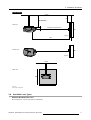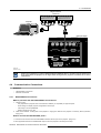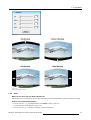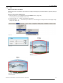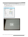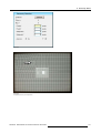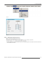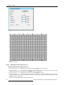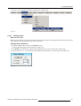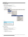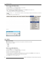
1
BarcoReality SIM 5plus/SIM 5R
Owner’s Manual
R9040380
R9040381
R5976870/03
04/04/2007
Product revision
Software version: V1.31
Barco nv Simulation Products
600 Bellbrook Ave, Xenia OH 45385
Phone: +1 (937) 372 7579
Fax: +1 (937) 372 8645
E-mail: [email protected]
Visit us at the web: www.eis.barco.com
Barco nv Simulation Products
Noordlaan 5, B-8520 Kuurne
Phone: +32 56.36.82.11
Fax: +32 56.36.84.86
E-mail: [email protected]
Visit us at the web: www.barco.com
Printed in Belgium
Copyright ©
All rights reserved. No part of this document may be copied, reproduced or translated. It shall not otherwise be recorded, transmitted or
stored in a retrieval system without the prior written consent of Barco.
Changes
Barco provides this manual ’as is’ without warranty of any kind, either expressed or implied, including but not limited to the implied warranties or merchantability and fitness for a particular purpose. Barco may make improvements and/or changes to the product(s) and/or the
program(s) described in this publication at any time without notice.
This publication could contain technical inaccuracies or typographical errors. Changes are periodically made to the information in this
publication; these changes are incorporated in new editions of this publication.
Trademarks
Brand and product names mentioned in this manual may be trademarks, registered trademarks or copyrights of their respective holders.
All brand and product names mentioned in this manual serve as comments or examples and are not to be understood as advertising for
the products or their manufactures.
Federal Communications Commission (FCC Statement)
This equipment has been tested and found to comply with the limits for a class A digital device, pursuant to Part 15 of the FCC rules.
These limits are designed to provide reasonable protection against harmful interference when the equipment is operated in a commercial
environment. This equipment generates, uses, and can radiate radio frequency energy and, if not installed and used in accordance with
the instruction manual, may cause harmful interference to radio communications. Operation of this equipment in a residential area may
cause harmful interference, in which case the user will be responsible for correcting any interference.
EN55022/CISPR22 Class A ITE (Information Technology Equipment)
Class A ITE is a category of all other ITE which satisfies the class A ITE limits but not the class B ITE limits. Such equipment should not
be restricted in its sale but the following warning shall be included in the instructions for use:
Warning : This is a class A product. In a domestic environment this product may cause radio interference in which case the user may be
required to take adequate measures.
Table of contents
TABLE OF CONTENTS
1. Safety Instructions . . . . . . . . . . . . . . . . . . . . . . . . . . . . . . . . . . . . . . . . . . . . . . . . . . . . . . . . . . . . . . . . . . . . . . . . . . . . . . . . . . . . . . . . . . . . . . . . . 5
1.1
1.2
Warnings . . . . . . . . . . . . . . . . . . . . . . . . . . . . . . . . . . . . . . . . . . . . . . . . . . . . . . . . . . . . . . . . . . . . . . . . . . . . . . . . . . . . . . . . . . . . . . . . . . . . . . . . . . . . . . . . . . . . . . . . . . . . . . 5
Note . . . . . . . . . . . . . . . . . . . . . . . . . . . . . . . . . . . . . . . . . . . . . . . . . . . . . . . . . . . . . . . . . . . . . . . . . . . . . . . . . . . . . . . . . . . . . . . . . . . . . . . . . . . . . . . . . . . . . . . .. . . . . . . . . . . 5
2. Packaging and Dimensions . . . . . . . . . . . . . . . . . . . . . . . . . . . . . . . . . . . . . . . . . . . . . . . . . . . . . . . . . . . . . . . . . . . . . . . . . . . . . . . . . . . . . . 7
2.1
2.2
2.3
2.4
Box Content. . . . . . . . . . . . . . . . . . . . . . . . . . . . . . . . . . . . . . . . . . . . . . . . . . . . . . . . . . . . . . . . . . . . . . . . . . . . . . . . . . . . . . . . . . . . . . . . . . . . . . . . . . . . . . . . . . . . . . . . . . .
Projector Packaging . . . . . . . . . . . . . . . . . . . . . . . . . . . . . . . . . . . . . . . . . . . . . . . . . . . . . . . . . . . . . . . . . . . . . . . . . . . . . . . . . . . . . . . . . . . . . . . . . . . . . . . . . . . . . . . . . .
Weight. . . . . . . . . . . . . . . . . . . . . . . . . . . . . . . . . . . . . . . . . . . . . . . . . . . . . . . . . . . . . . . . . . . . . . . . . . . . . . . . . . . . . . . . . . . . . . . . . . . . . . . . . . . . . . . . . . . . . . . . . . . . . . . . .
Dimensions . . . . . . . . . . . . . . . . . . . . . . . . . . . . . . . . . . . . . . . . . . . . . . . . . . . . . . . . . . . . . . . . . . . . . . . . . . . . . . . . . . . . . . . . . . . . . . . . . . . . . . . . . . . . . . . . . . . . . . . . . . .
7
7
8
8
3. Installation Guidelines. . . . . . . . . . . . . . . . . . . . . . . . . . . . . . . . . . . . . . . . . . . . . . . . . . . . . . . . . . . . . . . . . . . . . . . . . . . . . . . . . . . . . . . . . . . . 11
3.1
3.2
3.3
3.4
3.5
3.6
3.7
3.8
3.9
3.10
3.11
3.12
Safety Warnings . . . . . . . . . . . . . . . . . . . . . . . . . . . . . . . . . . . . . . . . . . . . . . . . . . . . . . . . . . . . . . . . . . . . . . . . . . . . . . . . . . . . . . . . . . . . . . . . . . . . . . . . . . . . . . . . . . . . . 11
General Installation Guidelines . . . . . . . . . . . . . . . . . . . . . . . . . . . . . . . . . . . . . . . . . . . . . . . . . . . . . . . . . . . . . . . . . . . . . . . . . . . . . . . . . . . . . . . . . . . . . . . . . . . . . 11
Projector Position . . . . . . . . . . . . . . . . . . . . . . . . . . . . . . . . . . . . . . . . . . . . . . . . . . . . . . . . . . . . . . . . . . . . . . . . . . . . . . . . . . . . . . . . . . . . . . . . . . . . . . . . . . . . . . . . . . . . 12
Airflow . . . . . . . . . . . . . . . . . . . . . . . . . . . . . . . . . . . . . . . . . . . . . . . . . . . . . . . . . . . . . . . . . . . . . . . . . . . . . . . . . . . . . . . . . . . . . . . . . . . . . . . . . . . . . . . . . . . . . . . . . . . . . . . . 14
Projector Configuration . . . . . . . . . . . . . . . . . . . . . . . . . . . . . . . . . . . . . . . . . . . . . . . . . . . . . . . . . . . . . . . . . . . . . . . . . . . . . . . . . . . . . . . . . . . . . . . . . . . . . . . . . . . . . . 16
Available Lens Types . . . . . . . . . . . . . . . . . . . . . . . . . . . . . . . . . . . . . . . . . . . . . . . . . . . . . . . . . . . . . . . . . . . . . . . . . . . . . . . . . . . . . . . . . . . . . . . . . . . . . . . . . . . . . . . . 17
Lens Formulas . . . . . . . . . . . . . . . . . . . . . . . . . . . . . . . . . . . . . . . . . . . . . . . . . . . . . . . . . . . . . . . . . . . . . . . . . . . . . . . . . . . . . . . . . . . . . . . . . . . . . . . . . . . . . . . . . . . . . . . 18
Lens Installation . . . . . . . . . . . . . . . . . . . . . . . . . . . . . . . . . . . . . . . . . . . . . . . . . . . . . . . . . . . . . . . . . . . . . . . . . . . . . . . . . . . . . . . . . . . . . . . . . . . . . . . . . . . . . . . . . . . . . 18
Lens Shift Capability. . . . . . . . . . . . . . . . . . . . . . . . . . . . . . . . . . . . . . . . . . . . . . . . . . . . . . . . . . . . . . . . . . . . . . . . . . . . . . . . . . . . . . . . . . . . . . . . . . . . . . . . . . . . . . . . . 21
Scheimpflug Lens Adjustment . . . . . . . . . . . . . . . . . . . . . . . . . . . . . . . . . . . . . . . . . . . . . . . . . . . . . . . . . . . . . . . . . . . . . . . . . . . . . . . . . . . . . . . . . . . . . . . . . . . . . . 22
Cleaning the lens . . . . . . . . . . . . . . . . . . . . . . . . . . . . . . . . . . . . . . . . . . . . . . . . . . . . . . . . . . . . . . . . . . . . . . . . . . . . . . . . . . . . . . . . . . . . . . . . . . . . . . . . . . . . . . . . . . . . 22
Battery Installation . . . . . . . . . . . . . . . . . . . . . . . . . . . . . . . . . . . . . . . . . . . . . . . . . . . . . . . . . . . . . . . . . . . . . . . . . . . . . . . . . . . . . . . . . . . . . . . . . . . . . . . . . . . . . . . . . . . 23
4. Connections. . . . . . . . . . . . . . . . . . . . . . . . . . . . . . . . . . . . . . . . . . . . . . . . . . . . . . . . . . . . . . . . . . . . . . . . . . . . . . . . . . . . . . . . . . . . . . . . . . . . . . . . 25
4.1
4.2
4.3
Connections Overview . . . . . . . . . . . . . . . . . . . . . . . . . . . . . . . . . . . . . . . . . . . . . . . . . . . . . . . . . . . . . . . . . . . . . . . . . . . . . . . . . . . . . . . . . . . . . . . . . . . . . . . . . . . . . . 25
Power Cord Connection . . . . . . . . . . . . . . . . . . . . . . . . . . . . . . . . . . . . . . . . . . . . . . . . . . . . . . . . . . . . . . . . . . . . . . . . . . . . . . . . . . . . . . . . . . . . . . . . . . . . . . . . . . . . . 26
Source Input Connections. . . . . . . . . . . . . . . . . . . . . . . . . . . . . . . . . . . . . . . . . . . . . . . . . . . . . . . . . . . . . . . . . . . . . . . . . . . . . . . . . . . . . . . . . . . . . . . . . . . . . . . . . . . 26
4.3.1 5–Cable Input . . . . . . . . . . . . . . . . . . . . . . . . . . . . . . . . . . . . . . . . . . . . . . . . . . . . . . . . . . . . . . . . . . . . . . . . . . . . . . . . . . . . . . . . . . . . . . . . . . . . . . . . . . . . . . . . . 27
4.3.2 DVI Input . . . . . . . . . . . . . . . . . . . . . . . . . . . . . . . . . . . . . . . . . . . . . . . . . . . . . . . . . . . . . . . . . . . . . . . . . . . . . . . . . . . . . . . . . . . . . . . . . . . . . . . . . . . . . . . . . . . . . . 27
4.3.3 Computer Input . . . . . . . . . . . . . . . . . . . . . . . . . . . . . . . . . . . . . . . . . . . . . . . . . . . . . . . . . . . . . . . . . . . . . . . . . . . . . . . . . . . . . . . . . . . . . . . . . . . . . . . . . . . . . . . 28
4.4 Communication Connections. . . . . . . . . . . . . . . . . . . . . . . . . . . . . . . . . . . . . . . . . . . . . . . . . . . . . . . . . . . . . . . . . . . . . . . . . . . . . . . . . . . . . . . . . . . . . . . . . . . . . . . . 29
4.4.1 RS232/RS422 Connections . . . . . . . . . . . . . . . . . . . . . . . . . . . . . . . . . . . . . . . . . . . . . . . . . . . . . . . . . . . . . . . . . . . . . . . . . . . . . . . . . . . . . . . . . . . . . . . . . . 29
4.4.2 Ethernet Connections . . . . . . . . . . . . . . . . . . . . . . . . . . . . . . . . . . . . . . . . . . . . . . . . . . . . . . . . . . . . . . . . . . . . . . . . . . . . . . . . . . . . . . . . . . . . . . . . . . . . . . . . . 30
5. Getting Started. . . . . . . . . . . . . . . . . . . . . . . . . . . . . . . . . . . . . . . . . . . . . . . . . . . . . . . . . . . . . . . . . . . . . . . . . . . . . . . . . . . . . . . . . . . . . . . . . . . . . 33
5.1
5.2
5.3
5.4
5.5
5.6
5.7
5.8
5.9
Operating the Projector. . . . . . . . . . . . . . . . . . . . . . . . . . . . . . . . . . . . . . . . . . . . . . . . . . . . . . . . . . . . . . . . . . . . . . . . . . . . . . . . . . . . . . . . . . . . . . . . . . . . . . . . . . . . . . 33
RCU Terminology Overview . . . . . . . . . . . . . . . . . . . . . . . . . . . . . . . . . . . . . . . . . . . . . . . . . . . . . . . . . . . . . . . . . . . . . . . . . . . . . . . . . . . . . . . . . . . . . . . . . . . . . . . . . 33
Local Keypad Terminology Overview . . . . . . . . . . . . . . . . . . . . . . . . . . . . . . . . . . . . . . . . . . . . . . . . . . . . . . . . . . . . . . . . . . . . . . . . . . . . . . . . . . . . . . . . . . . . . . . 34
Diagnose Leds. . . . . . . . . . . . . . . . . . . . . . . . . . . . . . . . . . . . . . . . . . . . . . . . . . . . . . . . . . . . . . . . . . . . . . . . . . . . . . . . . . . . . . . . . . . . . . . . . . . . . . . . . . . . . . . . . . . . . . . 35
Switching On. . . . . . . . . . . . . . . . . . . . . . . . . . . . . . . . . . . . . . . . . . . . . . . . . . . . . . . . . . . . . . . . . . . . . . . . . . . . . . . . . . . . . . . . . . . . . . . . . . . . . . . . . . . . . . . . . . . . . . . . . 36
Switching to Standby . . . . . . . . . . . . . . . . . . . . . . . . . . . . . . . . . . . . . . . . . . . . . . . . . . . . . . . . . . . . . . . . . . . . . . . . . . . . . . . . . . . . . . . . . . . . . . . . . . . . . . . . . . . . . . . . 37
Switching Off. . . . . . . . . . . . . . . . . . . . . . . . . . . . . . . . . . . . . . . . . . . . . . . . . . . . . . . . . . . . . . . . . . . . . . . . . . . . . . . . . . . . . . . . . . . . . . . . . . . . . . . . . . . . . . . . . . . . . . . . . 37
Pointing the RCU . . . . . . . . . . . . . . . . . . . . . . . . . . . . . . . . . . . . . . . . . . . . . . . . . . . . . . . . . . . . . . . . . . . . . . . . . . . . . . . . . . . . . . . . . . . . . . . . . . . . . . . . . . . . . . . . . . . . 38
Controlling the Projector. . . . . . . . . . . . . . . . . . . . . . . . . . . . . . . . . . . . . . . . . . . . . . . . . . . . . . . . . . . . . . . . . . . . . . . . . . . . . . . . . . . . . . . . . . . . . . . . . . . . . . . . . . . . . 38
5.9.1 Common Address . . . . . . . . . . . . . . . . . . . . . . . . . . . . . . . . . . . . . . . . . . . . . . . . . . . . . . . . . . . . . . . . . . . . . . . . . . . . . . . . . . . . . . . . . . . . . . . . . . . . . . . . . . . . . 38
5.9.2 Projector Address . . . . . . . . . . . . . . . . . . . . . . . . . . . . . . . . . . . . . . . . . . . . . . . . . . . . . . . . . . . . . . . . . . . . . . . . . . . . . . . . . . . . . . . . . . . . . . . . . . . . . . . . . . . . . 39
5.9.3 RCU Address . . . . . . . . . . . . . . . . . . . . . . . . . . . . . . . . . . . . . . . . . . . . . . . . . . . . . . . . . . . . . . . . . . . . . . . . . . . . . . . . . . . . . . . . . . . . . . . . . . . . . . . . . . . . . . . . . 39
6. Source Selection . . . . . . . . . . . . . . . . . . . . . . . . . . . . . . . . . . . . . . . . . . . . . . . . . . . . . . . . . . . . . . . . . . . . . . . . . . . . . . . . . . . . . . . . . . . . . . . . . . 41
6.1
6.2
6.3
6.4
Introduction . . . . . . . . . . . . . . . . . . . . . . . . . . . . . . . . . . . . . . . . . . . . . . . . . . . . . . . . . . . . . . . . . . . . . . . . . . . . . . . . . . . . . . . . . . . . . . . . . . . . . . . . . . . . . . . . . . . . . . . . . . 41
Source Selection Overview . . . . . . . . . . . . . . . . . . . . . . . . . . . . . . . . . . . . . . . . . . . . . . . . . . . . . . . . . . . . . . . . . . . . . . . . . . . . . . . . . . . . . . . . . . . . . . . . . . . . . . . . . 41
Source Selection Shortcut Keys . . . . . . . . . . . . . . . . . . . . . . . . . . . . . . . . . . . . . . . . . . . . . . . . . . . . . . . . . . . . . . . . . . . . . . . . . . . . . . . . . . . . . . . . . . . . . . . . . . . . 41
Source Selection . . . . . . . . . . . . . . . . . . . . . . . . . . . . . . . . . . . . . . . . . . . . . . . . . . . . . . . . . . . . . . . . . . . . . . . . . . . . . . . . . . . . . . . . . . . . . . . . . . . . . . . . . . . . . . . . . . . . 41
7. Image Menu . . . . . . . . . . . . . . . . . . . . . . . . . . . . . . . . . . . . . . . . . . . . . . . . . . . . . . . . . . . . . . . . . . . . . . . . . . . . . . . . . . . . . . . . . . . . . . . . . . . . . . . . 43
7.1
7.2
7.3
7.4
7.5
Image Menu Overview . . . . . . . . . . . . . . . . . . . . . . . . . . . . . . . . . . . . . . . . . . . . . . . . . . . . . . . . . . . . . . . . . . . . . . . . . . . . . . . . . . . . . . . . . . . . . . . . . . . . . . . . . . . . . . 43
Input Balance . . . . . . . . . . . . . . . . . . . . . . . . . . . . . . . . . . . . . . . . . . . . . . . . . . . . . . . . . . . . . . . . . . . . . . . . . . . . . . . . . . . . . . . . . . . . . . . . . . . . . . . . . . . . . . . . . . . . . . . . 43
Dynacolor™. . . . . . . . . . . . . . . . . . . . . . . . . . . . . . . . . . . . . . . . . . . . . . . . . . . . . . . . . . . . . . . . . . . . . . . . . . . . . . . . . . . . . . . . . . . . . . . . . . . . . . . . . . . . . . . . . . . . . . . . . . 48
Infitec. . . . . . . . . . . . . . . . . . . . . . . . . . . . . . . . . . . . . . . . . . . . . . . . . . . . . . . . . . . . . . . . . . . . . . . . . . . . . . . . . . . . . . . . . . . . . . . . . . . . . . . . . . . . . . . . . . . . . . . . . . . . . . . . . 57
Windowing . . . . . . . . . . . . . . . . . . . . . . . . . . . . . . . . . . . . . . . . . . . . . . . . . . . . . . . . . . . . . . . . . . . . . . . . . . . . . . . . . . . . . . . . . . . . . . . . . . . . . . . . . . . . . . . . . . . . . . . . . . . 57
7.5.1 Introduction. . . . . . . . . . . . . . . . . . . . . . . . . . . . . . . . . . . . . . . . . . . . . . . . . . . . . . . . . . . . . . . . . . . . . . . . . . . . . . . . . . . . . . . . . . . . . . . . . . . . . . . . . . . . . . . . . . . . 58
7.5.2 Starting Up Windowing . . . . . . . . . . . . . . . . . . . . . . . . . . . . . . . . . . . . . . . . . . . . . . . . . . . . . . . . . . . . . . . . . . . . . . . . . . . . . . . . . . . . . . . . . . . . . . . . . . . . . . . 58
7.5.3 Blanking . . . . . . . . . . . . . . . . . . . . . . . . . . . . . . . . . . . . . . . . . . . . . . . . . . . . . . . . . . . . . . . . . . . . . . . . . . . . . . . . . . . . . . . . . . . . . . . . . . . . . . . . . . . . . . . . . . . . . . . 58
7.5.4 Shift. . . . . . . . . . . . . . . . . . . . . . . . . . . . . . . . . . . . . . . . . . . . . . . . . . . . . . . . . . . . . . . . . . . . . . . . . . . . . . . . . . . . . . . . . . . . . . . . . . . . . . . . . . . . . . . . . . . . . . . . . . . . 59
7.5.5 Size . . . . . . . . . . . . . . . . . . . . . . . . . . . . . . . . . . . . . . . . . . . . . . . . . . . . . . . . . . . . . . . . . . . . . . . . . . . . . . . . . . . . . . . . . . . . . . . . . . . . . . . . . . . . . . . . . . . . . . . . . . . . 61
7.5.6 Blanking – Softedge . . . . . . . . . . . . . . . . . . . . . . . . . . . . . . . . . . . . . . . . . . . . . . . . . . . . . . . . . . . . . . . . . . . . . . . . . . . . . . . . . . . . . . . . . . . . . . . . . . . . . . . . . . 62
7.6 Settings . . . . . . . . . . . . . . . . . . . . . . . . . . . . . . . . . . . . . . . . . . . . . . . . . . . . . . . . . . . . . . . . . . . . . . . . . . . . . . . . . . . . . . . . . . . . . . . . . . . . . . . . . . . . . . . . . . . . . . . . . . . . . . 62
7.6.1 Introduction. . . . . . . . . . . . . . . . . . . . . . . . . . . . . . . . . . . . . . . . . . . . . . . . . . . . . . . . . . . . . . . . . . . . . . . . . . . . . . . . . . . . . . . . . . . . . . . . . . . . . . . . . . . . . . . . . . . . 62
7.6.2 Contrast . . . . . . . . . . . . . . . . . . . . . . . . . . . . . . . . . . . . . . . . . . . . . . . . . . . . . . . . . . . . . . . . . . . . . . . . . . . . . . . . . . . . . . . . . . . . . . . . . . . . . . . . . . . . . . . . . . . . . . . 62
7.6.3 Brightness . . . . . . . . . . . . . . . . . . . . . . . . . . . . . . . . . . . . . . . . . . . . . . . . . . . . . . . . . . . . . . . . . . . . . . . . . . . . . . . . . . . . . . . . . . . . . . . . . . . . . . . . . . . . . . . . . . . . . 63
7.6.4 Gamma . . . . . . . . . . . . . . . . . . . . . . . . . . . . . . . . . . . . . . . . . . . . . . . . . . . . . . . . . . . . . . . . . . . . . . . . . . . . . . . . . . . . . . . . . . . . . . . . . . . . . . . . . . . . . . . . . . . . . . . . 64
7.6.5 Phase. . . . . . . . . . . . . . . . . . . . . . . . . . . . . . . . . . . . . . . . . . . . . . . . . . . . . . . . . . . . . . . . . . . . . . . . . . . . . . . . . . . . . . . . . . . . . . . . . . . . . . . . . . . . . . . . . . . . . . . . . . 64
R5976870 BARCOREALITY SIM 5PLUS/SIM 5R 04/04/2007
1
Table of contents
7.7
7.6.6 Sharpness . . . . . . . . . . . . . . . . . . . . . . . . . . . . . . . . . . . . . . . . . . . . . . . . . . . . . . . . . . . . . . . . . . . . . . . . . . . . . . . . . . . . . . . . . . . . . . . . . . . . . . . . . . . . . . . . . . . . . 65
Video . . . . . . . . . . . . . . . . . . . . . . . . . . . . . . . . . . . . . . . . . . . . . . . . . . . . . . . . . . . . . . . . . . . . . . . . . . . . . . . . . . . . . . . . . . . . . . . . . . . . . . . . . . . . . . . . . . . . . . . . . . . . . . . . . 65
7.7.1 Tint (Hue). . . . . . . . . . . . . . . . . . . . . . . . . . . . . . . . . . . . . . . . . . . . . . . . . . . . . . . . . . . . . . . . . . . . . . . . . . . . . . . . . . . . . . . . . . . . . . . . . . . . . . . . . . . . . . . . . . . . . . 65
7.7.2 Color. . . . . . . . . . . . . . . . . . . . . . . . . . . . . . . . . . . . . . . . . . . . . . . . . . . . . . . . . . . . . . . . . . . . . . . . . . . . . . . . . . . . . . . . . . . . . . . . . . . . . . . . . . . . . . . . . . . . . . . . . . . 66
7.7.3 AGC on video . . . . . . . . . . . . . . . . . . . . . . . . . . . . . . . . . . . . . . . . . . . . . . . . . . . . . . . . . . . . . . . . . . . . . . . . . . . . . . . . . . . . . . . . . . . . . . . . . . . . . . . . . . . . . . . . . 66
7.7.4 Manual Gain Control . . . . . . . . . . . . . . . . . . . . . . . . . . . . . . . . . . . . . . . . . . . . . . . . . . . . . . . . . . . . . . . . . . . . . . . . . . . . . . . . . . . . . . . . . . . . . . . . . . . . . . . . . . 67
8. Geometry Menu . . . . . . . . . . . . . . . . . . . . . . . . . . . . . . . . . . . . . . . . . . . . . . . . . . . . . . . . . . . . . . . . . . . . . . . . . . . . . . . . . . . . . . . . . . . . . . . . . . . . 69
8.1
8.2
8.3
8.4
8.5
2
Introduction . . . . . . . . . . . . . . . . . . . . . . . . . . . . . . . . . . . . . . . . . . . . . . . . . . . . . . . . . . . . . . . . . . . . . . . . . . . . . . . . . . . . . . . . . . . . . . . . . . . . . . . . . . . . . . . . . . . . . . . . . . 69
Geometry Menu Overview . . . . . . . . . . . . . . . . . . . . . . . . . . . . . . . . . . . . . . . . . . . . . . . . . . . . . . . . . . . . . . . . . . . . . . . . . . . . . . . . . . . . . . . . . . . . . . . . . . . . . . . . . . 69
Geometry Files . . . . . . . . . . . . . . . . . . . . . . . . . . . . . . . . . . . . . . . . . . . . . . . . . . . . . . . . . . . . . . . . . . . . . . . . . . . . . . . . . . . . . . . . . . . . . . . . . . . . . . . . . . . . . . . . . . . . . . 70
Load Geometry File . . . . . . . . . . . . . . . . . . . . . . . . . . . . . . . . . . . . . . . . . . . . . . . . . . . . . . . . . . . . . . . . . . . . . . . . . . . . . . . . . . . . . . . . . . . . . . . . . . . . . . . . . . . . . . . . . 72
Edit Geometry File. . . . . . . . . . . . . . . . . . . . . . . . . . . . . . . . . . . . . . . . . . . . . . . . . . . . . . . . . . . . . . . . . . . . . . . . . . . . . . . . . . . . . . . . . . . . . . . . . . . . . . . . . . . . . . . . . . . 73
8.5.1 Introduction. . . . . . . . . . . . . . . . . . . . . . . . . . . . . . . . . . . . . . . . . . . . . . . . . . . . . . . . . . . . . . . . . . . . . . . . . . . . . . . . . . . . . . . . . . . . . . . . . . . . . . . . . . . . . . . . . . . . 74
8.5.2 3x3 Adjustment (Level 1-3) . . . . . . . . . . . . . . . . . . . . . . . . . . . . . . . . . . . . . . . . . . . . . . . . . . . . . . . . . . . . . . . . . . . . . . . . . . . . . . . . . . . . . . . . . . . . . . . . . . . 76
8.5.2.1
Starting up the 3x3 adjustment (Level 1-3) . . . . . . . . . . . . . . . . . . . . . . . . . . . . . . . . . . . . . . . . . . . . . . . . . . . . . . . . . . . . . . . . . . . . . . . . . . . . 76
8.5.2.2
Selecting the 3x3 Corners (Level 1) . . . . . . . . . . . . . . . . . . . . . . . . . . . . . . . . . . . . . . . . . . . . . . . . . . . . . . . . . . . . . . . . . . . . . . . . . . . . . . . . . . . 77
8.5.2.3
Adjusting the 3x3 Corners (Level 1) . . . . . . . . . . . . . . . . . . . . . . . . . . . . . . . . . . . . . . . . . . . . . . . . . . . . . . . . . . . . . . . . . . . . . . . . . . . . . . . . . . . 78
8.5.2.4
Selecting the 3x3 Side Bows (Level 2) . . . . . . . . . . . . . . . . . . . . . . . . . . . . . . . . . . . . . . . . . . . . . . . . . . . . . . . . . . . . . . . . . . . . . . . . . . . . . . . . 82
8.5.2.5
Setting up a bow shaped pre-distortion. . . . . . . . . . . . . . . . . . . . . . . . . . . . . . . . . . . . . . . . . . . . . . . . . . . . . . . . . . . . . . . . . . . . . . . . . . . . . . . . 83
8.5.2.6
Linearity adjustment using 3x3 Side Bows . . . . . . . . . . . . . . . . . . . . . . . . . . . . . . . . . . . . . . . . . . . . . . . . . . . . . . . . . . . . . . . . . . . . . . . . . . . . 85
8.5.2.7
Selecting the Center (Level 3) . . . . . . . . . . . . . . . . . . . . . . . . . . . . . . . . . . . . . . . . . . . . . . . . . . . . . . . . . . . . . . . . . . . . . . . . . . . . . . . . . . . . . . . . . 86
8.5.2.8
Adjusting the 3x3 Center (Level 3) . . . . . . . . . . . . . . . . . . . . . . . . . . . . . . . . . . . . . . . . . . . . . . . . . . . . . . . . . . . . . . . . . . . . . . . . . . . . . . . . . . . . 87
8.5.3 5x5 Adjustment (Level 4-6) . . . . . . . . . . . . . . . . . . . . . . . . . . . . . . . . . . . . . . . . . . . . . . . . . . . . . . . . . . . . . . . . . . . . . . . . . . . . . . . . . . . . . . . . . . . . . . . . . . . 89
8.5.3.1
Starting Up the 5x5 Adjustment (Level 4-6) . . . . . . . . . . . . . . . . . . . . . . . . . . . . . . . . . . . . . . . . . . . . . . . . . . . . . . . . . . . . . . . . . . . . . . . . . . . 89
8.5.3.2
Selecting the 5x5 H-side (Level 4). . . . . . . . . . . . . . . . . . . . . . . . . . . . . . . . . . . . . . . . . . . . . . . . . . . . . . . . . . . . . . . . . . . . . . . . . . . . . . . . . . . . . 90
8.5.3.3
Adjusting the 5x5 H-side (Level 4). . . . . . . . . . . . . . . . . . . . . . . . . . . . . . . . . . . . . . . . . . . . . . . . . . . . . . . . . . . . . . . . . . . . . . . . . . . . . . . . . . . . . 91
8.5.3.4
Selecting the 5x5 V-side (Level 4) . . . . . . . . . . . . . . . . . . . . . . . . . . . . . . . . . . . . . . . . . . . . . . . . . . . . . . . . . . . . . . . . . . . . . . . . . . . . . . . . . . . . . 93
8.5.3.5
Adjusting the 5x5 V-side (Level 4) . . . . . . . . . . . . . . . . . . . . . . . . . . . . . . . . . . . . . . . . . . . . . . . . . . . . . . . . . . . . . . . . . . . . . . . . . . . . . . . . . . . . . 94
8.5.3.6
Selecting the 5x5 Center (Level 5) . . . . . . . . . . . . . . . . . . . . . . . . . . . . . . . . . . . . . . . . . . . . . . . . . . . . . . . . . . . . . . . . . . . . . . . . . . . . . . . . . . . . 96
8.5.3.7
Adjusting the 5x5 Center (Level 5) . . . . . . . . . . . . . . . . . . . . . . . . . . . . . . . . . . . . . . . . . . . . . . . . . . . . . . . . . . . . . . . . . . . . . . . . . . . . . . . . . . . . 97
8.5.3.8
Selecting the 5x5 Quadrant (Level 6). . . . . . . . . . . . . . . . . . . . . . . . . . . . . . . . . . . . . . . . . . . . . . . . . . . . . . . . . . . . . . . . . . . . . . . . . . . . . . . . . . 99
8.5.3.9
Adjusting the 5x5 Quadrant (Level 6). . . . . . . . . . . . . . . . . . . . . . . . . . . . . . . . . . . . . . . . . . . . . . . . . . . . . . . . . . . . . . . . . . . . . . . . . . . . . . . . .100
8.5.4 9x9 Adjustment (Level 7-10). . . . . . . . . . . . . . . . . . . . . . . . . . . . . . . . . . . . . . . . . . . . . . . . . . . . . . . . . . . . . . . . . . . . . . . . . . . . . . . . . . . . . . . . . . . . . . . . .102
8.5.4.1
Starting up the 9x9 Adjustment (Level 7-10) . . . . . . . . . . . . . . . . . . . . . . . . . . . . . . . . . . . . . . . . . . . . . . . . . . . . . . . . . . . . . . . . . . . . . . . . .102
8.5.4.2
Selecting the 9x9 H-side (Level 7). . . . . . . . . . . . . . . . . . . . . . . . . . . . . . . . . . . . . . . . . . . . . . . . . . . . . . . . . . . . . . . . . . . . . . . . . . . . . . . . . . . .103
8.5.4.3
Adjusting the 9x9 H-side (Level 7). . . . . . . . . . . . . . . . . . . . . . . . . . . . . . . . . . . . . . . . . . . . . . . . . . . . . . . . . . . . . . . . . . . . . . . . . . . . . . . . . . . .104
8.5.4.4
Selecting the 9x9 V-side (Level 7) . . . . . . . . . . . . . . . . . . . . . . . . . . . . . . . . . . . . . . . . . . . . . . . . . . . . . . . . . . . . . . . . . . . . . . . . . . . . . . . . . . . .106
8.5.4.5
Adjusting the 9x9 V-side (Level 7) . . . . . . . . . . . . . . . . . . . . . . . . . . . . . . . . . . . . . . . . . . . . . . . . . . . . . . . . . . . . . . . . . . . . . . . . . . . . . . . . . . . .107
8.5.4.6
Selecting the 9x9 Center (Level 8) . . . . . . . . . . . . . . . . . . . . . . . . . . . . . . . . . . . . . . . . . . . . . . . . . . . . . . . . . . . . . . . . . . . . . . . . . . . . . . . . . . .109
8.5.4.7
Adjusting the 9x9 Center (Level 8) . . . . . . . . . . . . . . . . . . . . . . . . . . . . . . . . . . . . . . . . . . . . . . . . . . . . . . . . . . . . . . . . . . . . . . . . . . . . . . . . . . . 110
8.5.4.8
Selecting the 9x9 Quadrant (Level 9). . . . . . . . . . . . . . . . . . . . . . . . . . . . . . . . . . . . . . . . . . . . . . . . . . . . . . . . . . . . . . . . . . . . . . . . . . . . . . . . . 112
8.5.4.9
Adjusting the 9x9 Quadrant (Level 9). . . . . . . . . . . . . . . . . . . . . . . . . . . . . . . . . . . . . . . . . . . . . . . . . . . . . . . . . . . . . . . . . . . . . . . . . . . . . . . . . 113
8.5.4.10 Selecting the 9x9 Fine points (Level 10) . . . . . . . . . . . . . . . . . . . . . . . . . . . . . . . . . . . . . . . . . . . . . . . . . . . . . . . . . . . . . . . . . . . . . . . . . . . . . 115
8.5.4.11 Adjusting the 9x9 Fine points (Level 10) . . . . . . . . . . . . . . . . . . . . . . . . . . . . . . . . . . . . . . . . . . . . . . . . . . . . . . . . . . . . . . . . . . . . . . . . . . . . . 116
8.5.5 17x17 Adjustment (Level 11-15). . . . . . . . . . . . . . . . . . . . . . . . . . . . . . . . . . . . . . . . . . . . . . . . . . . . . . . . . . . . . . . . . . . . . . . . . . . . . . . . . . . . . . . . . . . . . 118
8.5.5.1
Starting up the 17x17 Adjustment (Level 11-15) . . . . . . . . . . . . . . . . . . . . . . . . . . . . . . . . . . . . . . . . . . . . . . . . . . . . . . . . . . . . . . . . . . . . . 118
8.5.5.2
Selecting the 17x17 H-side (Level 11) . . . . . . . . . . . . . . . . . . . . . . . . . . . . . . . . . . . . . . . . . . . . . . . . . . . . . . . . . . . . . . . . . . . . . . . . . . . . . . . . 119
8.5.5.3
Adjusting the 17x17 H-side (Level 11) . . . . . . . . . . . . . . . . . . . . . . . . . . . . . . . . . . . . . . . . . . . . . . . . . . . . . . . . . . . . . . . . . . . . . . . . . . . . . . . .120
8.5.5.4
Selecting the 17x17 V-side (Level 11) . . . . . . . . . . . . . . . . . . . . . . . . . . . . . . . . . . . . . . . . . . . . . . . . . . . . . . . . . . . . . . . . . . . . . . . . . . . . . . . .122
8.5.5.5
Adjusting the 17x17 V-side (Level 11) . . . . . . . . . . . . . . . . . . . . . . . . . . . . . . . . . . . . . . . . . . . . . . . . . . . . . . . . . . . . . . . . . . . . . . . . . . . . . . . .123
8.5.5.6
Selecting the 17x17 Center (Level 12) . . . . . . . . . . . . . . . . . . . . . . . . . . . . . . . . . . . . . . . . . . . . . . . . . . . . . . . . . . . . . . . . . . . . . . . . . . . . . . .125
8.5.5.7
Adjusting the 17x17 Center (Level 12) . . . . . . . . . . . . . . . . . . . . . . . . . . . . . . . . . . . . . . . . . . . . . . . . . . . . . . . . . . . . . . . . . . . . . . . . . . . . . . .126
8.5.5.8
Selecting the 17x17 Quadrant (Level 13) . . . . . . . . . . . . . . . . . . . . . . . . . . . . . . . . . . . . . . . . . . . . . . . . . . . . . . . . . . . . . . . . . . . . . . . . . . . .128
8.5.5.9
Adjusting the 17x17 Quadrant (Level 13) . . . . . . . . . . . . . . . . . . . . . . . . . . . . . . . . . . . . . . . . . . . . . . . . . . . . . . . . . . . . . . . . . . . . . . . . . . . .129
8.5.5.10 Selecting the 17x17 Fine points (Level 14). . . . . . . . . . . . . . . . . . . . . . . . . . . . . . . . . . . . . . . . . . . . . . . . . . . . . . . . . . . . . . . . . . . . . . . . . . .131
8.5.5.11 Adjusting the 17x17 Fine points (Level 14). . . . . . . . . . . . . . . . . . . . . . . . . . . . . . . . . . . . . . . . . . . . . . . . . . . . . . . . . . . . . . . . . . . . . . . . . . .132
8.5.5.12 Selecting the 17x17 Local points (Level 15). . . . . . . . . . . . . . . . . . . . . . . . . . . . . . . . . . . . . . . . . . . . . . . . . . . . . . . . . . . . . . . . . . . . . . . . . .134
8.5.5.13 Adjusting the 17x17 Local points (Level 15). . . . . . . . . . . . . . . . . . . . . . . . . . . . . . . . . . . . . . . . . . . . . . . . . . . . . . . . . . . . . . . . . . . . . . . . . .135
8.5.6 Shift Adjustment. . . . . . . . . . . . . . . . . . . . . . . . . . . . . . . . . . . . . . . . . . . . . . . . . . . . . . . . . . . . . . . . . . . . . . . . . . . . . . . . . . . . . . . . . . . . . . . . . . . . . . . . . . . . . .137
8.5.7 Transport Delay . . . . . . . . . . . . . . . . . . . . . . . . . . . . . . . . . . . . . . . . . . . . . . . . . . . . . . . . . . . . . . . . . . . . . . . . . . . . . . . . . . . . . . . . . . . . . . . . . . . . . . . . . . . . . .138
8.5.8 Blanking . . . . . . . . . . . . . . . . . . . . . . . . . . . . . . . . . . . . . . . . . . . . . . . . . . . . . . . . . . . . . . . . . . . . . . . . . . . . . . . . . . . . . . . . . . . . . . . . . . . . . . . . . . . . . . . . . . . . . .139
8.5.9 Softedge . . . . . . . . . . . . . . . . . . . . . . . . . . . . . . . . . . . . . . . . . . . . . . . . . . . . . . . . . . . . . . . . . . . . . . . . . . . . . . . . . . . . . . . . . . . . . . . . . . . . . . . . . . . . . . . . . . . . .141
8.5.9.1
Introduction . . . . . . . . . . . . . . . . . . . . . . . . . . . . . . . . . . . . . . . . . . . . . . . . . . . . . . . . . . . . . . . . . . . . . . . . . . . . . . . . . . . . . . . . . . . . . . . . . . . . . . . . . . . .141
8.5.9.2
Starting Up the Softedge Adjustment. . . . . . . . . . . . . . . . . . . . . . . . . . . . . . . . . . . . . . . . . . . . . . . . . . . . . . . . . . . . . . . . . . . . . . . . . . . . . . . . .142
8.5.9.3
Softedge Shape . . . . . . . . . . . . . . . . . . . . . . . . . . . . . . . . . . . . . . . . . . . . . . . . . . . . . . . . . . . . . . . . . . . . . . . . . . . . . . . . . . . . . . . . . . . . . . . . . . . . . . .143
8.5.9.4
Basic Softedge Shape Setup . . . . . . . . . . . . . . . . . . . . . . . . . . . . . . . . . . . . . . . . . . . . . . . . . . . . . . . . . . . . . . . . . . . . . . . . . . . . . . . . . . . . . . . . .145
8.5.9.5
Softedge Width . . . . . . . . . . . . . . . . . . . . . . . . . . . . . . . . . . . . . . . . . . . . . . . . . . . . . . . . . . . . . . . . . . . . . . . . . . . . . . . . . . . . . . . . . . . . . . . . . . . . . . . .147
8.5.9.6
Basic Softedge Width Setup . . . . . . . . . . . . . . . . . . . . . . . . . . . . . . . . . . . . . . . . . . . . . . . . . . . . . . . . . . . . . . . . . . . . . . . . . . . . . . . . . . . . . . . . . .147
8.5.10 Geometry Reset. . . . . . . . . . . . . . . . . . . . . . . . . . . . . . . . . . . . . . . . . . . . . . . . . . . . . . . . . . . . . . . . . . . . . . . . . . . . . . . . . . . . . . . . . . . . . . . . . . . . . . . . . . . . . .149
8.5.10.1 Starting Up. . . . . . . . . . . . . . . . . . . . . . . . . . . . . . . . . . . . . . . . . . . . . . . . . . . . . . . . . . . . . . . . . . . . . . . . . . . . . . . . . . . . . . . . . . . . . . . . . . . . . . . . . . . . .149
8.5.10.2 Reset All Levels . . . . . . . . . . . . . . . . . . . . . . . . . . . . . . . . . . . . . . . . . . . . . . . . . . . . . . . . . . . . . . . . . . . . . . . . . . . . . . . . . . . . . . . . . . . . . . . . . . . . . . .150
8.5.10.3 Restore 3x3. . . . . . . . . . . . . . . . . . . . . . . . . . . . . . . . . . . . . . . . . . . . . . . . . . . . . . . . . . . . . . . . . . . . . . . . . . . . . . . . . . . . . . . . . . . . . . . . . . . . . . . . . . . .150
8.5.10.4 Restore 5x5. . . . . . . . . . . . . . . . . . . . . . . . . . . . . . . . . . . . . . . . . . . . . . . . . . . . . . . . . . . . . . . . . . . . . . . . . . . . . . . . . . . . . . . . . . . . . . . . . . . . . . . . . . . .151
8.5.10.5 Restore 9x9. . . . . . . . . . . . . . . . . . . . . . . . . . . . . . . . . . . . . . . . . . . . . . . . . . . . . . . . . . . . . . . . . . . . . . . . . . . . . . . . . . . . . . . . . . . . . . . . . . . . . . . . . . . .152
8.5.10.6 Reset Softedge Width . . . . . . . . . . . . . . . . . . . . . . . . . . . . . . . . . . . . . . . . . . . . . . . . . . . . . . . . . . . . . . . . . . . . . . . . . . . . . . . . . . . . . . . . . . . . . . . . .153
R5976870 BARCOREALITY SIM 5PLUS/SIM 5R 04/04/2007
Table of contents
8.6
8.7
8.8
8.5.10.7 Reset Softedge All . . . . . . . . . . . . . . . . . . . . . . . . . . . . . . . . . . . . . . . . . . . . . . . . . . . . . . . . . . . . . . . . . . . . . . . . . . . . . . . . . . . . . . . . . . . . . . . . . . . .154
8.5.10.8 Full Reset . . . . . . . . . . . . . . . . . . . . . . . . . . . . . . . . . . . . . . . . . . . . . . . . . . . . . . . . . . . . . . . . . . . . . . . . . . . . . . . . . . . . . . . . . . . . . . . . . . . . . . . . . . . . . .155
Rename Geometry File. . . . . . . . . . . . . . . . . . . . . . . . . . . . . . . . . . . . . . . . . . . . . . . . . . . . . . . . . . . . . . . . . . . . . . . . . . . . . . . . . . . . . . . . . . . . . . . . . . . . . . . . . . . . .156
Copy Geometry File . . . . . . . . . . . . . . . . . . . . . . . . . . . . . . . . . . . . . . . . . . . . . . . . . . . . . . . . . . . . . . . . . . . . . . . . . . . . . . . . . . . . . . . . . . . . . . . . . . . . . . . . . . . . . . . .157
Delete Geometry File . . . . . . . . . . . . . . . . . . . . . . . . . . . . . . . . . . . . . . . . . . . . . . . . . . . . . . . . . . . . . . . . . . . . . . . . . . . . . . . . . . . . . . . . . . . . . . . . . . . . . . . . . . . . . . .158
9. Tools Menu . . . . . . . . . . . . . . . . . . . . . . . . . . . . . . . . . . . . . . . . . . . . . . . . . . . . . . . . . . . . . . . . . . . . . . . . . . . . . . . . . . . . . . . . . . . . . . . . . . . . . . . 161
9.1
9.2
Tools Menu Overview. . . . . . . . . . . . . . . . . . . . . . . . . . . . . . . . . . . . . . . . . . . . . . . . . . . . . . . . . . . . . . . . . . . . . . . . . . . . . . . . . . . . . . . . . . . . . . . . . . . . . . . . . . . . . . .161
Diagnostics . . . . . . . . . . . . . . . . . . . . . . . . . . . . . . . . . . . . . . . . . . . . . . . . . . . . . . . . . . . . . . . . . . . . . . . . . . . . . . . . . . . . . . . . . . . . . . . . . . . . . . . . . . . . . . . . . . . . . . . . .161
9.2.1 I²C . . . . . . . . . . . . . . . . . . . . . . . . . . . . . . . . . . . . . . . . . . . . . . . . . . . . . . . . . . . . . . . . . . . . . . . . . . . . . . . . . . . . . . . . . . . . . . . . . . . . . . . . . . . . . . . . . . . . . . .. . . . .161
9.2.2 Lamps and Power Supply . . . . . . . . . . . . . . . . . . . . . . . . . . . . . . . . . . . . . . . . . . . . . . . . . . . . . . . . . . . . . . . . . . . . . . . . . . . . . . . . . . . . . . . . . . . . . . . . . . .162
9.2.3 Formatter . . . . . . . . . . . . . . . . . . . . . . . . . . . . . . . . . . . . . . . . . . . . . . . . . . . . . . . . . . . . . . . . . . . . . . . . . . . . . . . . . . . . . . . . . . . . . . . . . . . . . . . . . . . . . . . . . . . . .163
9.3 Ethernet Connection. . . . . . . . . . . . . . . . . . . . . . . . . . . . . . . . . . . . . . . . . . . . . . . . . . . . . . . . . . . . . . . . . . . . . . . . . . . . . . . . . . . . . . . . . . . . . . . . . . . . . . . . . . . . . . . .163
9.4 Picture in Picture . . . . . . . . . . . . . . . . . . . . . . . . . . . . . . . . . . . . . . . . . . . . . . . . . . . . . . . . . . . . . . . . . . . . . . . . . . . . . . . . . . . . . . . . . . . . . . . . . . . . . . . . . . . . . . . . . . .164
10. Lamps Menu. . . . . . . . . . . . . . . . . . . . . . . . . . . . . . . . . . . . . . . . . . . . . . . . . . . . . . . . . . . . . . . . . . . . . . . . . . . . . . . . . . . . . . . . . . . . . . . . . . . . . . 169
10.1 Lamps Menu Overview . . . . . . . . . . . . . . . . . . . . . . . . . . . . . . . . . . . . . . . . . . . . . . . . . . . . . . . . . . . . . . . . . . . . . . . . . . . . . . . . . . . . . . . . . . . . . . . . . . . . . . . . . . . . .169
10.2 Lamp Runtimes . . . . . . . . . . . . . . . . . . . . . . . . . . . . . . . . . . . . . . . . . . . . . . . . . . . . . . . . . . . . . . . . . . . . . . . . . . . . . . . . . . . . . . . . . . . . . . . . . . . . . . . . . . . . . . . . . . . . .169
10.3 Mode . . . . . . . . . . . . . . . . . . . . . . . . . . . . . . . . . . . . . . . . . . . . . . . . . . . . . . . . . . . . . . . . . . . . . . . . . . . . . . . . . . . . . . . . . . . . . . . . . . . . . . . . . . . . . . . . . . . . . . . . . . . . . . . .170
10.4 Lamp History. . . . . . . . . . . . . . . . . . . . . . . . . . . . . . . . . . . . . . . . . . . . . . . . . . . . . . . . . . . . . . . . . . . . . . . . . . . . . . . . . . . . . . . . . . . . . . . . . . . . . . . . . . . . . . . . . . . . . . . .172
10.5 Lamp Reset Runtime . . . . . . . . . . . . . . . . . . . . . . . . . . . . . . . . . . . . . . . . . . . . . . . . . . . . . . . . . . . . . . . . . . . . . . . . . . . . . . . . . . . . . . . . . . . . . . . . . . . . . . . . . . . . . . .173
10.6 Clear Lamp Error . . . . . . . . . . . . . . . . . . . . . . . . . . . . . . . . . . . . . . . . . . . . . . . . . . . . . . . . . . . . . . . . . . . . . . . . . . . . . . . . . . . . . . . . . . . . . . . . . . . . . . . . . . . . . . . . . . .174
10.7 Lamp Runtime Warning . . . . . . . . . . . . . . . . . . . . . . . . . . . . . . . . . . . . . . . . . . . . . . . . . . . . . . . . . . . . . . . . . . . . . . . . . . . . . . . . . . . . . . . . . . . . . . . . . . . . . . . . . . . .174
10.8 Light Output. . . . . . . . . . . . . . . . . . . . . . . . . . . . . . . . . . . . . . . . . . . . . . . . . . . . . . . . . . . . . . . . . . . . . . . . . . . . . . . . . . . . . . . . . . . . . . . . . . . . . . . . . . . . . . . . . . . . . . . . .175
10.8.1 Light Sensor. . . . . . . . . . . . . . . . . . . . . . . . . . . . . . . . . . . . . . . . . . . . . . . . . . . . . . . . . . . . . . . . . . . . . . . . . . . . . . . . . . . . . . . . . . . . . . . . . . . . . . . . . . . . . . . . . .175
10.8.2 Constant Light Output (CLO) . . . . . . . . . . . . . . . . . . . . . . . . . . . . . . . . . . . . . . . . . . . . . . . . . . . . . . . . . . . . . . . . . . . . . . . . . . . . . . . . . . . . . . . . . . . . . . . .176
10.8.3 Dimmer . . . . . . . . . . . . . . . . . . . . . . . . . . . . . . . . . . . . . . . . . . . . . . . . . . . . . . . . . . . . . . . . . . . . . . . . . . . . . . . . . . . . . . . . . . . . . . . . . . . . . . . . . . . . . . . . . . . . . . .177
10.8.4 Dimmer Reference Positions . . . . . . . . . . . . . . . . . . . . . . . . . . . . . . . . . . . . . . . . . . . . . . . . . . . . . . . . . . . . . . . . . . . . . . . . . . . . . . . . . . . . . . . . . . . . . . . .178
11. Image Files Menu. . . . . . . . . . . . . . . . . . . . . . . . . . . . . . . . . . . . . . . . . . . . . . . . . . . . . . . . . . . . . . . . . . . . . . . . . . . . . . . . . . . . . . . . . . . . . . . . 183
11.1
11.2
11.3
11.4
11.5
11.6
11.7
11.8
Image Files Menu Overview . . . . . . . . . . . . . . . . . . . . . . . . . . . . . . . . . . . . . . . . . . . . . . . . . . . . . . . . . . . . . . . . . . . . . . . . . . . . . . . . . . . . . . . . . . . . . . . . . . . . . . .183
Source Files . . . . . . . . . . . . . . . . . . . . . . . . . . . . . . . . . . . . . . . . . . . . . . . . . . . . . . . . . . . . . . . . . . . . . . . . . . . . . . . . . . . . . . . . . . . . . . . . . . . . . . . . . . . . . . . . . . . . . . . .183
Load. . . . . . . . . . . . . . . . . . . . . . . . . . . . . . . . . . . . . . . . . . . . . . . . . . . . . . . . . . . . . . . . . . . . . . . . . . . . . . . . . . . . . . . . . . . . . . . . . . . . . . . . . . . . . . . . . . . . . . . . . . . . . . . . .184
File Load . . . . . . . . . . . . . . . . . . . . . . . . . . . . . . . . . . . . . . . . . . . . . . . . . . . . . . . . . . . . . . . . . . . . . . . . . . . . . . . . . . . . . . . . . . . . . . . . . . . . . . . . . . . . . . . . . . . . . . . . . . . .185
Edit . . . . . . . . . . . . . . . . . . . . . . . . . . . . . . . . . . . . . . . . . . . . . . . . . . . . . . . . . . . . . . . . . . . . . . . . . . . . . . . . . . . . . . . . . . . . . . . . . . . . . . . . . . . . . . . . . . . . . . . . . . . . . . . . . .185
Rename . . . . . . . . . . . . . . . . . . . . . . . . . . . . . . . . . . . . . . . . . . . . . . . . . . . . . . . . . . . . . . . . . . . . . . . . . . . . . . . . . . . . . . . . . . . . . . . . . . . . . . . . . . . . . . . . . . . . . . . . . . . . .188
Copy . . . . . . . . . . . . . . . . . . . . . . . . . . . . . . . . . . . . . . . . . . . . . . . . . . . . . . . . . . . . . . . . . . . . . . . . . . . . . . . . . . . . . . . . . . . . . . . . . . . . . . . . . . . . . . . . . . . . . . . . . . . . . . . .189
Delete . . . . . . . . . . . . . . . . . . . . . . . . . . . . . . . . . . . . . . . . . . . . . . . . . . . . . . . . . . . . . . . . . . . . . . . . . . . . . . . . . . . . . . . . . . . . . . . . . . . . . . . . . . . . . . . . . . . . . . . . . . . . . . .189
12. Display Setup Menu. . . . . . . . . . . . . . . . . . . . . . . . . . . . . . . . . . . . . . . . . . . . . . . . . . . . . . . . . . . . . . . . . . . . . . . . . . . . . . . . . . . . . . . . . . . . . 191
12.1
12.2
12.3
12.4
Menu Bar Position . . . . . . . . . . . . . . . . . . . . . . . . . . . . . . . . . . . . . . . . . . . . . . . . . . . . . . . . . . . . . . . . . . . . . . . . . . . . . . . . . . . . . . . . . . . . . . . . . . . . . . . . . . . . . . . . . .191
Status Bar position . . . . . . . . . . . . . . . . . . . . . . . . . . . . . . . . . . . . . . . . . . . . . . . . . . . . . . . . . . . . . . . . . . . . . . . . . . . . . . . . . . . . . . . . . . . . . . . . . . . . . . . . . . . . . . . . .191
Sliderbox Position . . . . . . . . . . . . . . . . . . . . . . . . . . . . . . . . . . . . . . . . . . . . . . . . . . . . . . . . . . . . . . . . . . . . . . . . . . . . . . . . . . . . . . . . . . . . . . . . . . . . . . . . . . . . . . . . . .192
Text Box. . . . . . . . . . . . . . . . . . . . . . . . . . . . . . . . . . . . . . . . . . . . . . . . . . . . . . . . . . . . . . . . . . . . . . . . . . . . . . . . . . . . . . . . . . . . . . . . . . . . . . . . . . . . . . . . . . . . . . . . . . . . .193
13. Installation Menu . . . . . . . . . . . . . . . . . . . . . . . . . . . . . . . . . . . . . . . . . . . . . . . . . . . . . . . . . . . . . . . . . . . . . . . . . . . . . . . . . . . . . . . . . . . . . . . . 195
13.1 Lens Adjustment . . . . . . . . . . . . . . . . . . . . . . . . . . . . . . . . . . . . . . . . . . . . . . . . . . . . . . . . . . . . . . . . . . . . . . . . . . . . . . . . . . . . . . . . . . . . . . . . . . . . . . . . . . . . . . . . . . . .195
13.2 Identification . . . . . . . . . . . . . . . . . . . . . . . . . . . . . . . . . . . . . . . . . . . . . . . . . . . . . . . . . . . . . . . . . . . . . . . . . . . . . . . . . . . . . . . . . . . . . . . . . . . . . . . . . . . . . . . . . . . . . . . .196
13.3 Projector Address. . . . . . . . . . . . . . . . . . . . . . . . . . . . . . . . . . . . . . . . . . . . . . . . . . . . . . . . . . . . . . . . . . . . . . . . . . . . . . . . . . . . . . . . . . . . . . . . . . . . . . . . . . . . . . . . . . .197
13.4 Orientation . . . . . . . . . . . . . . . . . . . . . . . . . . . . . . . . . . . . . . . . . . . . . . . . . . . . . . . . . . . . . . . . . . . . . . . . . . . . . . . . . . . . . . . . . . . . . . . . . . . . . . . . . . . . . . . . . . . . . . . . . .199
13.5 Color Wheel Index . . . . . . . . . . . . . . . . . . . . . . . . . . . . . . . . . . . . . . . . . . . . . . . . . . . . . . . . . . . . . . . . . . . . . . . . . . . . . . . . . . . . . . . . . . . . . . . . . . . . . . . . . . . . . . . . . .199
13.6 RS232. . . . . . . . . . . . . . . . . . . . . . . . . . . . . . . . . . . . . . . . . . . . . . . . . . . . . . . . . . . . . . . . . . . . . . . . . . . . . . . . . . . . . . . . . . . . . . . . . . . . . . . . . . . . . . . . . . . . . . . . . . . . . . .200
13.7 Internal Patterns . . . . . . . . . . . . . . . . . . . . . . . . . . . . . . . . . . . . . . . . . . . . . . . . . . . . . . . . . . . . . . . . . . . . . . . . . . . . . . . . . . . . . . . . . . . . . . . . . . . . . . . . . . . . . . . . . . . .201
13.8 Scaled Patterns. . . . . . . . . . . . . . . . . . . . . . . . . . . . . . . . . . . . . . . . . . . . . . . . . . . . . . . . . . . . . . . . . . . . . . . . . . . . . . . . . . . . . . . . . . . . . . . . . . . . . . . . . . . . . . . . . . . . .205
13.9 Automatic Startup . . . . . . . . . . . . . . . . . . . . . . . . . . . . . . . . . . . . . . . . . . . . . . . . . . . . . . . . . . . . . . . . . . . . . . . . . . . . . . . . . . . . . . . . . . . . . . . . . . . . . . . . . . . . . . . . . .209
13.10 Background . . . . . . . . . . . . . . . . . . . . . . . . . . . . . . . . . . . . . . . . . . . . . . . . . . . . . . . . . . . . . . . . . . . . . . . . . . . . . . . . . . . . . . . . . . . . . . . . . . . . . . . . . . . . . . . . . . . . . . . . .210
13.11 Factory Preset CWI. . . . . . . . . . . . . . . . . . . . . . . . . . . . . . . . . . . . . . . . . . . . . . . . . . . . . . . . . . . . . . . . . . . . . . . . . . . . . . . . . . . . . . . . . . . . . . . . . . . . . . . . . . . . . . . . . 211
14. Service Menu. . . . . . . . . . . . . . . . . . . . . . . . . . . . . . . . . . . . . . . . . . . . . . . . . . . . . . . . . . . . . . . . . . . . . . . . . . . . . . . . . . . . . . . . . . . . . . . . . . . . . 213
14.1 Options. . . . . . . . . . . . . . . . . . . . . . . . . . . . . . . . . . . . . . . . . . . . . . . . . . . . . . . . . . . . . . . . . . . . . . . . . . . . . . . . . . . . . . . . . . . . . . . . . . . . . . . . . . . . . . . . . . . . . . . . . . . . . .213
14.2 Version Table . . . . . . . . . . . . . . . . . . . . . . . . . . . . . . . . . . . . . . . . . . . . . . . . . . . . . . . . . . . . . . . . . . . . . . . . . . . . . . . . . . . . . . . . . . . . . . . . . . . . . . . . . . . . . . . . . . . . . . .213
15. Adjustment Menu. . . . . . . . . . . . . . . . . . . . . . . . . . . . . . . . . . . . . . . . . . . . . . . . . . . . . . . . . . . . . . . . . . . . . . . . . . . . . . . . . . . . . . . . . . . . . . . . 215
15.1 Preset Input Balance . . . . . . . . . . . . . . . . . . . . . . . . . . . . . . . . . . . . . . . . . . . . . . . . . . . . . . . . . . . . . . . . . . . . . . . . . . . . . . . . . . . . . . . . . . . . . . . . . . . . . . . . . . . . . . .215
15.2 Force Lamp Mode . . . . . . . . . . . . . . . . . . . . . . . . . . . . . . . . . . . . . . . . . . . . . . . . . . . . . . . . . . . . . . . . . . . . . . . . . . . . . . . . . . . . . . . . . . . . . . . . . . . . . . . . . . . . . . . . . .215
A. Standard Image Files. . . . . . . . . . . . . . . . . . . . . . . . . . . . . . . . . . . . . . . . . . . . . . . . . . . . . . . . . . . . . . . . . . . . . . . . . . . . . . . . . . . . . . . . . . . . . 217
A.1
Table overview . . . . . . . . . . . . . . . . . . . . . . . . . . . . . . . . . . . . . . . . . . . . . . . . . . . . . . . . . . . . . . . . . . . . . . . . . . . . . . . . . . . . . . . . . . . . . . . . . . . . . . . . . . . . . . . . . . . . . .217
B. Scheimpflug Lens Adjustment . . . . . . . . . . . . . . . . . . . . . . . . . . . . . . . . . . . . . . . . . . . . . . . . . . . . . . . . . . . . . . . . . . . . . . . . . . . . . . . . . 223
B.1
B.2
B.3
Introduction . . . . . . . . . . . . . . . . . . . . . . . . . . . . . . . . . . . . . . . . . . . . . . . . . . . . . . . . . . . . . . . . . . . . . . . . . . . . . . . . . . . . . . . . . . . . . . . . . . . . . . . . . . . . . . . . . . . . . . . . .223
Top–Bottom Scheimpflug Adjustment. . . . . . . . . . . . . . . . . . . . . . . . . . . . . . . . . . . . . . . . . . . . . . . . . . . . . . . . . . . . . . . . . . . . . . . . . . . . . . . . . . . . . . . . . . . . . .223
Left-Right Scheimpflug Adjustment . . . . . . . . . . . . . . . . . . . . . . . . . . . . . . . . . . . . . . . . . . . . . . . . . . . . . . . . . . . . . . . . . . . . . . . . . . . . . . . . . . . . . . . . . . . . . . . .225
C. Calibrate Measured Values. . . . . . . . . . . . . . . . . . . . . . . . . . . . . . . . . . . . . . . . . . . . . . . . . . . . . . . . . . . . . . . . . . . . . . . . . . . . . . . . . . . . . . 229
C.1
Calibrate Measured Values . . . . . . . . . . . . . . . . . . . . . . . . . . . . . . . . . . . . . . . . . . . . . . . . . . . . . . . . . . . . . . . . . . . . . . . . . . . . . . . . . . . . . . . . . . . . . . . . . . . . . . . .229
R5976870 BARCOREALITY SIM 5PLUS/SIM 5R 04/04/2007
3
Table of contents
D. Software Update . . . . . . . . . . . . . . . . . . . . . . . . . . . . . . . . . . . . . . . . . . . . . . . . . . . . . . . . . . . . . . . . . . . . . . . . . . . . . . . . . . . . . . . . . . . . . . . . . . 233
D.1
Software Update . . . . . . . . . . . . . . . . . . . . . . . . . . . . . . . . . . . . . . . . . . . . . . . . . . . . . . . . . . . . . . . . . . . . . . . . . . . . . . . . . . . . . . . . . . . . . . . . . . . . . . . . . . . . . . . . . . . .233
E. Troubleshoot. . . . . . . . . . . . . . . . . . . . . . . . . . . . . . . . . . . . . . . . . . . . . . . . . . . . . . . . . . . . . . . . . . . . . . . . . . . . . . . . . . . . . . . . . . . . . . . . . . . . . . . 237
E.1
Troubleshoot . . . . . . . . . . . . . . . . . . . . . . . . . . . . . . . . . . . . . . . . . . . . . . . . . . . . . . . . . . . . . . . . . . . . . . . . . . . . . . . . . . . . . . . . . . . . . . . . . . . . . . . . . . . . . . . . . . . . . . . .237
Index. . . . . . . . . . . . . . . . . . . . . . . . . . . . . . . . . . . . . . . . . . . . . . . . . . . . . . . . . . . . . . . . . . . . . . . . . . . . . . . . . . . . . . . . . . . . . . . . . . . . . . . . . . . . . . . . . . . . 239
4
R5976870 BARCOREALITY SIM 5PLUS/SIM 5R 04/04/2007
1. Safety Instructions
1. SAFETY INSTRUCTIONS
1.1
Warnings
To prevent personnel injury
Insure that the projector is installed in an easy to evacuate room in case of a lamp explosion.
The customer should never attempt to disassemble the lamp casing or to dispose of the lamp casing other than by returning it to
BARCO.
To prevent injuries and physical damage, always read this manual and all labels on the system before connecting to the wall outlet,
or adjusting the projector.
NEVER look into the lens ! Due to the high luminance damage to the eye can happen.
Before attempting to remove the projector’s cover, you must turn off the projector and disconnect from the wall outlet.
When performing set up work at a ceiling mounted projector, to prevent injury caused by falling objects or the system, set out a keep
out area.
Consult a professional structural engineer prior to suspending the ceiling mount from a structure not intended for that use. Always
ensure the working load limit of the structure supporting the projector.
The power input at the projector side is considered as the disconnect device. When mentioned to switch of the projector, to access
some parts inside, always disconnect the power cord at the projector side.
To prevent projector damage
If the Air Filters are not regularly replaced, the air flow inside the projector could be disrupted, causing overheating. Overheating
may lead to the projector shutting down during operation.
In order to ensure that correct airflow is maintained, and that the projector complies with Electromagnetic Compatibility requirements,
it should always be operated with all of it’s covers in place.
Ensure that nothing can be spilled on, or dropped inside the projector. If this does happen, switch off and unplug the mains supply
immediately. Do not operate the projector again until it has been checked by qualified service personnel.
The projector must always be mounted in a manner which ensures free flow of air into its air inlets and unimpeded evacuation of the
hot air exhausted from its cooling system. Heat sensitive materials should not be placed in the path of the exhausted air.
Special care should be used when DLP projectors are used in the same room as performant laser equipment. Direct or indirect
hitting of a laser beam on to the lens can severely damage the Digital Mirror Devices (TM) in which case there is a loss of warranty
To prevent battery explosion
Danger of explosion if battery is incorrectly replaced.
Replace only with the same or equivalent type recommended by the manufacturer.
Dispose of used batteries according to the manufacturer’s instructions.
1.2
Note
Definitions
Definition Qualified service technicians or Qualified technicians : Persons having appropriate technical training and experience necessary to be aware of hazards to which they are exposed in performing a task and of measures to minimize the danger to themselves
or other persons.
Extra Safety manual
Read also safety instructions in separate manual (R5976125).
R5976870 BARCOREALITY SIM 5PLUS/SIM 5R 04/04/2007
5
1. Safety Instructions
6
R5976870 BARCOREALITY SIM 5PLUS/SIM 5R 04/04/2007
2. Packaging and Dimensions
2. PACKAGING AND DIMENSIONS
Overview
•
Box Content
•
Projector Packaging
•
Weight
•
Dimensions
2.1
Box Content
CEE7
European power plug to connect the power cord to the wall outlet.
ANSI 73.11
American power plug to connect the power cord to the wall outlet.
Box Content
2.2
•
1 BarcoReality SIM 5plus Projector
•
1 Remote Control Unit (RCU) + 2 Batteries 1,5V
•
1 European and 1 American Power Cable
•
1 Owners manual
•
1 Safety manual
Projector Packaging
Way of Packaging
The projector is packed in a carton box. To provide protection during transportation, the projector is surrounded with foam. The
package is secured with banding and fastening clips.
How to Unpack?
1. Release the fastening clips.
2. Remove the banding. Handle as shown in the drawing. (image 2-1)
3. Take the projector out of its shipping carton and place it on a table. (image 2-2)
R5976870 BARCOREALITY SIM 5PLUS/SIM 5R 04/04/2007
7
2. Packaging and Dimensions
SIM 5 Plus
PULL
TO OPE
Image 2-1
Remove the banding
Image 2-2
Take the projector out of its shipping carton
Save the original shipping carton and packing material, they will be necessary if you ever have to ship your
projector. For maximum protection, repack your projector as it was originally packed at the factory.
Save the original shipping carton and packing material, they will be necessary if you ever have to ship your
projector. For maximum protection, repack your projector as it was originally packed at the factory.
CAUTION:
Never transport the projector with the lens mounted on it !
Always remove the lens before transporting the projector.
2.3
Weight
Weight
2.4
•
Projector body: 12.9 kg (28.4 lb)
•
Shipping weight: 17.5 kg (38.6 lb)
Dimensions
Dimensions
The dimensions are given in mm and inch (25,4mm = 1 inch).
8
R5976870 BARCOREALITY SIM 5PLUS/SIM 5R 04/04/2007
2. Packaging and Dimensions
281 mm
(11.06 inch)
305,2 mm
(12.02 inch)
152,6 mm
(6.01 inch)
487 mm (Length without Cable Basket)
(19.17 inch)
45 mm
(1.77 inch)
380,6 mm
(14.98 inch)
78,6 mm
(3.09 inch)
195
+12
0 mm
+0.47
(7.68 0 inch)
Image 2-3
Bottom view dimensions
Image 2-4
Front view dimensions
20
+12
0 mm
+0.47
(0.79 0 inch)
69
+12
-4 mm
+0.47
(2.72 -0.16 inch)
Length with different lenses: See table
Lens
QCLD (0.85:1)
QCLD (1.1-1.3:1)
CLD (1.2-1.6:1)
CLD (1.6-2.4:1)
CLD (2.4-4.3:1)
Length of Projector
610 mm
580 mm
530 mm
525 mm
550 mm
(24.02 inch)
(22.84 inch)
(20.87 inch)
(20.67 inch)
(21.65 inch)
Image 2-5
Left view dimensions
R5976870 BARCOREALITY SIM 5PLUS/SIM 5R 04/04/2007
9
2. Packaging and Dimensions
415 mm
(16.34 inch)
Image 2-6
Rear view dimensions
565 mm (Length with Cable Basket)
(22.24 inch)
Image 2-7
Right view dimensions
415 mm
(16.34 inch)
Image 2-8
Top view dimensions
10
R5976870 BARCOREALITY SIM 5PLUS/SIM 5R 04/04/2007
3. Installation Guidelines
3. INSTALLATION GUIDELINES
Overview
•
Safety Warnings
•
General Installation Guidelines
•
Projector Position
•
Airflow
•
Projector Configuration
•
Available Lens Types
•
Lens Formulas
•
Lens Installation
•
Lens Shift Capability
•
Scheimpflug Lens Adjustment
•
Cleaning the lens
•
Battery Installation
WARNING: Before installing the projector, read first the safety instructions supplied with the BarcoReality
SIM 5plus.
3.1
Safety Warnings
Mercury Vapor Warnings
Keep the following warnings in mind when using the projector. The lamp used in the projector contains mercury. In case of a lamp
rupture, explosion there will be a mercury vapor emission. In order to minimize the potential risk of inhaling mercury vapors:
3.2
•
Ensure the projector is installed only in ventilated rooms.
•
Replace the lamp module before the end of its operational life.
•
Promptly ventilate the room after a lamp rupture, explosion has occurred, evacuate the room (particularly in case of a pregnant
woman).
•
Seek medical attention if unusual health conditions occur after a lamp rupture, explosion, such as headache, fatigue, shortness
of breath, chest-tightening coughing or nausea.
General Installation Guidelines
Ambient Temperature Conditions
Careful consideration of things such as image size, ambient light level, projector placement and type of screen to use are critical to
the optimum use of the projection system.
Min. ambient temperature : 10°C or 50°F.
Max. ambient temperature : 40°C or 104°F.
The projector will not operate if ambient air temperature falls outside this range 10°C to 40°C (50°F to 104°F).
Storage temperature: -35°C to +65°C (-31°F to 149°F).
Humidity Conditions
Storage: 0 to 98 % RH Non-condensing.
Operation: 0 to 95 % RH Non-condensing.
CAUTION:
Harmful Environmental Contamination Precaution
R5976870 BARCOREALITY SIM 5PLUS/SIM 5R 04/04/2007
11
3. Installation Guidelines
Environment
Do not install the projection system in a site near heat sources such as radiators or air ducts, or in a place subject to direct sunlight,
excessive dust or humidity. Be aware that room heat rises to the ceiling; check that temperature near the installation site is not
excessive.
Environment Condition Check
A projector must always be mounted in a manner which ensures the free flow of clean air into the projectors ventilation inlets. For
installations in environments where the projector is subject to airborne contaminants such as that produced by smoke machines or
similar (these deposit a thin layer of greasy residue upon the projectors internal optics and imaging electronic surfaces, degrading
performance), then it is highly advisable and desirable to have this contamination removed prior to it reaching the projectors clean
air supply. Devices or structures to extract or shield contaminated air well away from the projector are a prerequisite, if this is not a
feasible solution then measures to relocate the projector to a clean air environment should be considered.
Only ever use the manufactures recommended cleaning kit which has been specifically designed for cleaning optical parts, never
use industrial strength cleaners on a projectors optics as these will degrade optical coatings and damage sensitive optoelectronics
components. Failure to take suitable precautions to protect the projector from the effects of persistent and prolonged air contaminants will culminate in extensive and irreversible ingrained optical damage. At this stage cleaning of the internal optical units will be
non-effective and impracticable. Damage of this nature is under no circumstances covered under the manufactures warranty and
may deem the warranty null and void. In such a case the client shall be held solely responsible for all costs incurred during any
repair. It is the clients responsibility to ensure at all times that the projector is protected from the harmful effects of hostile airborne
particles in the environment of the projector. The manufacture reserves the right to refuse repair if a projector has been subject to
wantful neglect, abandon or improper use.
What about Ambient Light?
The ambient light level of any room is made up of direct or indirect sunlight and the light fixtures in the room. The amount of ambient
light will determine how bright the image will appear. So, avoid direct light on the screen. Windows that face the screen should be
covered by opaque drapery while the set is being viewed. It is desirable to install the projection system in a room whose walls and
floor are of non-reflecting material. The use of recessed ceiling lights and a method of dimming those lights to an acceptable level
is also important. Too much ambient light will ‘wash out’ of the projected image. This appears as less contrast between the darkest
and lightest parts of the image. With bigger screens, the ‘wash out’ becomes more important. As a general rule, darken the room to
the point where there is just sufficient light to read or write comfortably. Spot lighting is desirable for illuminating small areas so that
interference with the screen is minimal.
Special Care for Laser Beams
Special care should be used when DLP projectors are used in the same room as performant laser equipment. Direct or indirect
hitting of a laser beam on to the lens can severely damage the Digital Mirror Devices (TM) in which case there is a loss of warranty.
Which Screen Type?
There are two major categories of screens used for projection equipment. Those used for front projected images and those for rear
projection applications.
Screens are rated by how much light they reflect (or transmit in the case of rear projection systems) given a determined amount
of light projected toward them. The ‘GAIN’ of a screen is the term used. Front and rear screens are both rated in terms of gain.
The gain of screens range from a white matte screen with a gain of 1 (x1) to a brushed aluminized screen with a gain of 10 (x10)
or more. The choice between higher and lower gain screens is largely a matter of personal preference and another consideration
called the Viewing angle. In considering the type of screen to choose, determine where the viewers will be located and go for the
highest gain screen possible. A high gain screen will provide a brighter picture but reduce the viewing angle. For more information
about screens, contact your local screen supplier.
What Image Size?
The projector is designed for projecting an image size from 1.00m (3.3ft) to 6.00m (19.7ft) with an aspect ratio of 4 to 3.
3.3
Projector Position
CAUTION: Improper positioning of the projector may reduce the lamp life and result in severe accident or fire
hazard.
Projector Position
Keep following projector position guidelines in mind when installing the projector:
12
R5976870 BARCOREALITY SIM 5PLUS/SIM 5R 04/04/2007
3. Installation Guidelines
•
+/- 20° roll around projector lens
+20° Roll around projector lens
-20° Roll around projector lens
Image 3-1
+/- 20° roll around projector lens
R5976870 BARCOREALITY SIM 5PLUS/SIM 5R 04/04/2007
13
3. Installation Guidelines
•
full pitching allowed (360°)
Full pitching
allowed (360 °)
Image 3-2
Full pitching allowed (360°)
•
Do not put the projector on either side to project an image
Do not put the projector
on either side
to project an image!
Image 3-3
Do not put the projector on either side to project an image
3.4
Airflow
Airflow
The Air Intake Vent is located on the bottom side of the projector while the Exhaust Vent can be found on the left rear side of the
projector. Make sure the projector is installed in a location so that the air inlets and outlets for the cooling system are not obstructed.
14
R5976870 BARCOREALITY SIM 5PLUS/SIM 5R 04/04/2007
3. Installation Guidelines
•
Air intake vent
Cold Air In
Cold Air In
Image 3-4
Air intake vent
•
Exhaust vent
Hot Air Out
Image 3-5
CAUTION: To protect the BarcoReality SIM 5plus from overheating do not cover or block the air intake and/or
exhaust vent.
CAUTION:
Do not place flammable objects near the Exhaust Vent.
CAUTION: Do not touch the Exhaust Vent Grill when the projector is switched on, this part will become hot
during operation.
R5976870 BARCOREALITY SIM 5PLUS/SIM 5R 04/04/2007
15
3. Installation Guidelines
3.5
Projector Configuration
Available Configurations
The projector can be installed to project images in four different configurations:
•
Front Table
•
Front Ceiling
•
Rear Table
•
Rear Ceiling
Positioning the Projector
The projector should be installed perpendicular with the screen on a distance PD (Projector Position) and water leveled in both
directions. The mounting positions in following images are shown for a nominal lens position.
PD
Front Table
Projector
Optical axis projection lens
Side view
SH
A
Screen
CD=SH/2+B-A
B
Floor
Top view
SW
Screen
SW
Back view
SH
Floor
Image 3-6
Front Table Configuration
16
R5976870 BARCOREALITY SIM 5PLUS/SIM 5R 04/04/2007
3. Installation Guidelines
Front Ceiling
Ceiling
B
CD=SH/2+B-A
Side view
A
Optical axis projection lens
SH
Projector
Screen
PD
Bottom view
SW
Screen
Ceiling
Back view
SH
SW
Image 3-7
Front Ceiling Configuration
3.6
Available Lens Types
Standard Non-Motorized Lens
Non-motorized lens: manual zoom and focus adjustment.
R5976870 BARCOREALITY SIM 5PLUS/SIM 5R 04/04/2007
17
3. Installation Guidelines
•
QCLD 1.1 – 1.3 :1 (Full off-axis)
Optional Motorized Lenses
Motorized lens: motorized zoom and focus adjustment.
•
CLD 1.2 – 1.6 :1 (Full off-axis)
•
CLD 1.6 – 2.4 :1 (Full off-axis)
•
CLD 2.4 – 4.3 :1 (Full off-axis)
Optional Fixed Lens
Fixed lens: manual focus adjustment.
•
QCLD 0.85 :1 (On-axis)
Product Numbers
3.7
Lens
Product Number
Product Number (Scheimpflug Version)
QCLD (0.85:1)
R9849860
R9849862
QCLD (1.1-1.3:1)
R9849850
R9849852
CLD (1.2-1.6:1)
R9849870
R9849872
CLD (1.6-2.4:1)
R9849880
R9849882
CLD (2.4-4.3:1)
R9849890
R9849892
Lens Formulas
Formulas
Lenses
Metric Formulas (meter)
QCLD (0.85:1)
PD = 0.86 X SW + 0.06
PD = 0.86 X SW + 2.36
QCLD (1.1-1.3:1)
PD min = 1.1 X SW + 0.05
PD min = 1.1 X SW + 1.97
PD max = 1.3 X SW + 0.06
PD max = 1.3 X SW + 2.36
CLD (1.2-1.6:1)
CLD (1.6-2.4:1)
CLD (2.4-4.3:1)
3.8
Inch formulas (inch)
PD min = 1.19 X SW + 0.02
PD min = 1.19 X SW + 0.79
PD max = 1.63 X SW + 0.02
PD max = 1.63 X SW + 0.79
PD min = 1.58 X SW + 0.00
PD min = 1.58 X SW + 0.00
PD max = 2.39 X SW - 0.02
PD max = 2.39 X SW - 0.79
PD min = 2.38 X SW - 0.03
PD min = 2.38 X SW - 1.18
PD max = 4.32 X SW - 0.01
PD max = 4.32 X SW - 0.39
Lens Installation
Necessary tools
No tools.
How to install the Lens?
1. Take the lens out of its packing material.
2. Make sure the lens lock holder is in the left position. (image 3-8)
3. Lock the lens by placing it in the housing, push carefully to lock (“click” sound) the lens in the housing. (image 3-9)
Caution: In case of a motorized lens the female jack on the lens (A) must be in front of the male jack (B) located in the upper-left
part of the housing in the projector. (image 3-10)
Note:
18
In case of a Scheimpflug lens, insert the lens with the adjustment bolts located in the left and bottom position. (image 3-11)
R5976870 BARCOREALITY SIM 5PLUS/SIM 5R 04/04/2007
3. Installation Guidelines
Image 3-8
Make sure the lens lock holder is in the left position.
Image 3-9
R5976870 BARCOREALITY SIM 5PLUS/SIM 5R 04/04/2007
19
3. Installation Guidelines
Image 3-10
The female jack on the lens (A) must be in front of the male jack (B) located in the upper-left part of the housing in the projector.
Image 3-11
In case of a Scheimpflug lens, insert the lens with the adjustment bolts located in the left and bottom position.
A Scheimpflug lens will limit shift possibilities. Mount the lens depending on the application (adjustment bolts
located in the left and bottom position to allow maximum shift up and in the left/top position to allow maximum
shift down)
CAUTION: The projector is delivered by default with a 100% upward shifted position.
Scheimpflug lens, first shift down.
20
To mount the
R5976870 BARCOREALITY SIM 5PLUS/SIM 5R 04/04/2007
3. Installation Guidelines
How to remove the Lens?
1. Support the lens with one hand.
2. The lens lock handle is located on the front side of the projector, slide this handle to the right. (image 3-12)
3. Remove the lens out of its housing.
4. Slide the lens lock handle back to the left.
Image 3-12
The lens lock handle is located on the front side of the projector, slide this handle to the right.
3.9
Lens Shift Capability
Introduction
The integrated Lens Shift Capabilities make the BarcoReality SIM 5plus easy to install in a variety of positions without the use of
special mechanical interfaces.
R5976870 BARCOREALITY SIM 5PLUS/SIM 5R 04/04/2007
21
3. Installation Guidelines
Vertical Lens Shift Range
•
Off-axis adjustable Vertical Lens Shift Range: +100% to –30%:
Vertical Shift in Nominal Position
Projector
Vertical Shift : +100%
Vertical Shift : -25%
Projector
Projector
Screen
Screen
Screen
Image 3-13
Vertical Lens Shift Range: +100% to –30%
Horizontal Lens Shift Range
•
Off-axis adjustable Horizontal Lens Shift Range: +100% in one direction (away from the inputs):
Horizontal Shift in Nominal Position
Projector
Horizontal Shift : +100%
Projector
Screen
Screen
Image 3-14
Horizontal Lens Shift Range: +100% in one direction (away from the inputs)
3.10 Scheimpflug Lens Adjustment
The Scheimpflug Lens Version is available as an option.
Scheimpflug Lens Adjustment
For more info on how to perform the Scheimpflug Lens Adjustment on a Scheimpflug lens see "Scheimpflug Lens Adjustment", page
223.
3.11 Cleaning the lens
To minimize the possibility of damage to optical coatings, or scratches to lens surfaces, we have developed
recommendations for cleaning. FIRST, we recommend you try to remove any material from the lens by blowing
it off with clean, dry deionized air. DO NOT use any liquid to clean the lenses.
Necessary tools
Toraysee TM cloth (delivered together with the lens kit). Order number : R379058.
How to clean the lens ?
Proceed as follow :
1. Always wipe lenses with a CLEAN Toraysee TM cloth.
22
R5976870 BARCOREALITY SIM 5PLUS/SIM 5R 04/04/2007
3. Installation Guidelines
2. Always wipe lenses in a single direction.
Warning: Do not wipe back and forwards across the lens surface as this tends to grind dirt into the coating.
3. Do not leave cleaning cloth in either an open room or lab coat pocket, as doing so can contaminate the cloth.
4. If smears occur when cleaning lenses, replace the cloth. Smears are the first indication of a dirty cloth.
CAUTION: Do not use fabric softener when washing the cleaning cloth or softener sheets when drying the
cloth.
Do not use liquid cleaners on the cloth as doing so will contaminate the cloth.
Other lenses can also be cleaned safely with this Toraysee TM cloth.
3.12 Battery Installation
How to install?
The batteries, not yet installed to save the battery life time, are delivered inside the plastic bag with the power cord.
1. Remove the battery cover on the backside of the remote control by pushing the indicated handle a little towards the bottom of
the RCU. (image 3-15)
2. Lift up the top side of the cover at the same time. (image 3-16)
3. Insert the 2 new 1,5 V batteries as indicated in the RCU. (image 3-17)
4. Put the battery cover back in place.
Image 3-15
Push the indicated handle
RCU Top
+
Image 3-17
Insert the 2 batteries
Image 3-16
Lift up the cover
R5976870 BARCOREALITY SIM 5PLUS/SIM 5R 04/04/2007
23
3. Installation Guidelines
24
R5976870 BARCOREALITY SIM 5PLUS/SIM 5R 04/04/2007
4. Connections
4. CONNECTIONS
Overview
4.1
•
Connections Overview
•
Power Cord Connection
•
Source Input Connections
•
Communication Connections
Connections Overview
Connections Overview
The following table gives an overview of the available connections found on the BarcoReality SIM 5plus:
I
0
1
Image 4-1
Power Cord Connection
2
6
R / PR
G/Y
B / PB
Hs / Cs
Vs
3
4
Optional
Optional
5
9
COMPUTER
DVI
RS 232 C
R.C.
14
Communication
11
10
RS232/422 IN
RS232/422 OUT
OUT Phased L/R Signal
10/100Base-T
12
13
IN L/R Signal
7
8
Image 4-2
Connections Overview
Power Cord Connection
1
Power Cord Connection
Source Input Connections
2
5–BNC Cable Input
3
For future expansion
4
For future expansion
R5976870 BARCOREALITY SIM 5PLUS/SIM 5R 04/04/2007
25
4. Connections
5
DVI Input (Single link up to 165 MHz)
6
VGA D15 connector
Stereo Connections
7
Not used
8
Not used
Communication Connections
4.2
9
RS232 Input (DB9 connector)
10
RS232/422 In (DB9 connector)
11
RS232/422 Out (DB9 connector)
12
10/100 Base-T In
13
10/100 Base-T Out / Link
14
Not used
Power Cord Connection
Power Input Range
The power input is auto-ranging from 90–254 VAC @ 50/60 Hz.
Power Consumption
Power Consumption of 1 BarcoReality SIM 5plus is 750 W.
Power Cord Connection
1. Use the supplied power cord to connect your projector to the wall outlet. Plug the female power connector into the male connector
at the front of the projector. (image 4-3)
I
0
to wall outlet
Image 4-3
Power Cord Connection
Fuses
For continued protection against fire hazard:
•
Refer replacement to qualified service personnel.
•
Ask to replace with the same type of fuse.
4.3
Source Input Connections
Overview
26
•
5–Cable Input
•
DVI Input
•
Computer Input
R5976870 BARCOREALITY SIM 5PLUS/SIM 5R 04/04/2007
4. Connections
4.3.1
5–Cable Input
Which signals can be connected to the 5–Cable Input?
Input Signal / BNC
Connector
R
G
B
H
V
RGBHV
R
G
B
H
V
RGBS
R
G
B
S
–
RGsB
R
Gs
B
–
–
Option
To display Component, the software option (ROPT2023) has to be activated.
How to connect to the 5–Cable Input?
1. Connect the BNC’s from the source signal output cable to the 5–Cable Input on the projector. (image 4-4)
Sim 5 plus Inputs
Image Generator
R / PR
G/Y
B / PB
DVI
Hs / Cs
Vs
COMPUTER
Optional
RS 232 C
Optional
R.C.
Communication
RS232/422 IN
RS232/422 OUT
OUT Phased L/R Signal
10/100Base-T
IN L/R Signal
Image 4-4
5–Cable Input
4.3.2
DVI Input
DVI
Digital Visual Interface is a display interface developed in response to the proliferation of digital flat panel displays.
The digital video connectivity standard that was developed by DDWG (Digital Display Work Group). This connection
standard offers two different connectors: one with 24 pins that handles digital video signals only, and one with 29 pins
that handles both digital and analog video. This standard uses TMDS (Transition Minimized Differential Signal) from
Silicon Image and DDC (Display Data Channel) from VESA (Video Electronics Standards Association).
DVI can be single or dual link.
How to connect the DVI Input?
1. Connect the DVI connector from the source signal output cable to the DVI Input on the projector. (image 4-5)
R5976870 BARCOREALITY SIM 5PLUS/SIM 5R 04/04/2007
27
4. Connections
Sim 5 plus Inputs
Image Generator
R / PR
G/Y
B / PB
DVI
Hs / Cs
Vs
COMPUTER
Optional
RS 232 C
Optional
R.C.
Communication
RS232/422 IN
RS232/422 OUT
OUT Phased L/R Signal
10/100Base-T
IN L/R Signal
Image 4-5
DVI Input
4.3.3
Computer Input
How to connect the Computer Input?
1. Connect the VGA D15 connector from the source signal output cable to the DVI Input on the projector. (image 4-6)
28
R5976870 BARCOREALITY SIM 5PLUS/SIM 5R 04/04/2007
4. Connections
Magik Interface II
(R9828122)
Input
Output
Computer
Sim 5 plus Inputs
R / PR
G/Y
B / PB
DVI
Hs / Cs
Vs
COMPUTER
Optional
RS 232 C
Optional
R.C.
Communication
RS232/422 IN
RS232/422 OUT
OUT Phased L/R Signal
10/100Base-T
IN L/R Signal
Image 4-6
Computer Input
Always use an interface (e.g. Barco’s Magik II Interface R9828122) when a computer and local monitor have
to be connected to the projector as the signal cable coming from the projector is limited to 60 cm due to
interferences.
4.4
Communication Connections
Overview
•
RS232/RS422 Connections
•
Ethernet Connections
4.4.1
RS232/RS422 Connections
What is possible with the RS232/RS422 Connections?
1.
2.
Remote control :
-
easy adjustment of projector when connected to an IBM PC (or compatible) or Apple computer.
-
allow storage of multiple projector configurations and set ups.
-
wide range of control possibilities.
-
address range from 0 to 255.
Data communications: sending data to the projector or copying the data from the projector to a memory device (hard disc,
floppy, etc.).
How to connect the RS232/RS422 ports?
1. Connect the D9 connector from the RS232/RS422 cable to the RS Input on the projector. (image 4-7)
2. When applicable connect the RS232/RS422 Output to the next projector in the daisy chain setup.
R5976870 BARCOREALITY SIM 5PLUS/SIM 5R 04/04/2007
29
4. Connections
PC Serial Port
To RS IN Port
on next projector
R / PR
G/Y
B / PB
DVI
Hs / Cs
Vs
Optional
COMPUTER
RS 232 C
Optional
R.C.
Communication
RS232/422 IN
RS232/422 OUT
OUT Phased L/R Signal
10/100Base-T
IN L/R Signal
Image 4-7
RS232/RS422 Connections
4.4.2
Ethernet Connections
What is possible with the Ethernet Connections?
The Ethernet Connections can be used to:
•
Upload or download projector software.
•
Set up RS232 communication (TCP-packets) with the projector.
How to connect the Ethernet ports?
1. Plug one end of the TCP/IP cable into the PC or the network socket. (image 4-8)
2. Connect the other end of the TCP/IP cable into the ’Ethernet In’ port on the projector.
The orange led will light up when network activity is detected.
30
R5976870 BARCOREALITY SIM 5PLUS/SIM 5R 04/04/2007
4. Connections
10/100 Base-T
R / PR
G/Y
B / PB
DVI
Hs / Cs
Vs
COMPUTER
Optional
RS 232 C
Optional
R.C.
Communication
RS232/422 IN
RS232/422 OUT
OUT Phased L/R Signal
10/100Base-T
IN L/R Signal
Image 4-8
Ethernet Connections
R5976870 BARCOREALITY SIM 5PLUS/SIM 5R 04/04/2007
31
4. Connections
32
R5976870 BARCOREALITY SIM 5PLUS/SIM 5R 04/04/2007
5. Getting Started
5. GETTING STARTED
5.1
Operating the Projector
How to Operate the Projector?
The projector can be controlled by using:
5.2
•
the Remote Control Unit (RCU).
•
the Local Keypad on top of the Projector.
•
the RS232 commands.
RCU Terminology Overview
What keys can be found on the RCU?
1
F2
F1
19
F3
2
18
3
MENU
BACK
4
17
16
ENTER
5
PAUSE
6
LOGO
PIP
15
14
AUTO IMAGE
DIGI
7
ZOOM
8
9
10
9
0
SDI
IQ-PC
7
8
DVI
Fire Wire
5
6
VIDEO
S-VIDEO
3
4
RGB
PC
1
2
LENS
ZOOM
PHASE
13
12
TINT
11
COLOR
BRIGHTN
CONTR
LENS
SHIFT
LENS
FOCUS
VOL
Image 5-1
RCU Overview
The following table gives an overview of the different functionalities of the keys that can be found on the RCU:
1
Function keys
Not used
2
MENU
Menu key, to enter or exit the Toolbar menu
3
Address key
(Recessed key), to enter the address of the projector (between 0 and 9). Press the recessed
address key with a pencil, followed by pressing one digit button between 0 and 9
4
LOGO
Switch between displaying the internal or external pattern in the Geometry Distortion and the
Shape (Blanking) dialogbox.
5
PAUSE
To stop projection for a short time, press ’PAUSE’. The image disappears but full power is
retained for immediate restarting.
6
STANDBY
Standby button, to start projector when the power switch is switched on and to switch off the
projector without switching off the power switch
Attention: Switching to Standby. When the projector is running and you want to go to
standby, press the standby key for 2 seconds.
R5976870 BARCOREALITY SIM 5PLUS/SIM 5R 04/04/2007
33
5. Getting Started
5.3
7
MUTE
Not used
8
Auto image
Not used
9
Digit buttons
Direct input selection
10
Lens control
Use these button to obtain the desired ZOOM, SHIFT, FOCUS
11
VOL
Not used
12
Picture Controls
Use these buttons to obtain the desired picture analog level
13
DIGI ZOOM
Not used
14
FREEZ
Not used
15
PIP
Not used
16
ENTER
To confirm an adjustment or selection in the menu
17
Cursor keys
To make menu selections, to perform bare scale adjustments or to zoom/focus when the direct
access is active
18
BACK
To leave the selected menu or item (go upwards to previous menu)
19
RCU operation
indication led
Lights up when a button on the remote control is pressed. (This is a visual indicator to check
the operation of the remote control)
Local Keypad Terminology Overview
What keys can be found on the Local Keypad?
Local Keypad
19
20
21
SOURCE
LENS
22
23
24
25
Image 5-2
Local Keypad Overview
34
R5976870 BARCOREALITY SIM 5PLUS/SIM 5R 04/04/2007
5. Getting Started
The following table gives an overview of the different functionalities of the keys that can be found on the Local Keypad:
19
Cursor keys
To make menu selections, to perform bare scale adjustments or to zoom/focus when the direct
access is active
20
ENTER
To start up the adjustment mode or to confirm an adjustment or selection in the adjustment mode
21
BACK
To leave the selected menu or item (go upwards to previous menu)
22
SOURCE
Not used
23
Lens control
Use these buttons to obtain the desired ZOOM, SHIFT and FOCUS
24
STANDBY
Standby button, to start projector when the power switch is switched on and to switch off the
projector without switching off the power switch
Attention : Switching to Standby. When the projector is running and you want to go to
standby, press the standby key for 2 seconds.
25
5.4
IR Receiver
IR Receiver
Diagnose Leds
Diagnose Leds
LED 1
LED 3
LED 2
Diagnose Leds
Image 5-3
Diagnose Leds
Following diagnose leds can be found on top of the projector:
Led # / Led Color
Green
Red
Led 1
Cool down sequence: flickers 60
seconds after switching to standby
Rescue program (Software error)
R5976870 BARCOREALITY SIM 5PLUS/SIM 5R 04/04/2007
35
5. Getting Started
5.5
Led # / Led Color
Green
Red
Led 2
Not used
Hardware error
Led 3
IR acknowledgement
Standby Status
Switching On
How to Switch On the Projector?
1. Press the Power Switch on the Left Front of the Projector to switch on the projector. (image 5-4)
The projector starts up in standby mode and Led 3 will light up red.
I
0
Image 5-4
Power Switch
When automatic startup is set to ’On’, the projector will immediately start with image projection (see "Automatic Startup", page 209).
How to Start Image Projection?
1. Press the STANDBY key (or the Source Selection Shortcut Digit) on the RCU or on the Local Keypad. (image 5-5)
Note: When automatic startup is set to ’On’, the projector will immediately start with image projection when swithing the projector
’On’ (see "Automatic Startup", page 209).
The projector will start up, following message will be displayed, according to the used Dynacolor™ settings, the message display
time can vary between 5 to 30 seconds. (image 5-6)
The ’Please Wait’ message will disappear and the identification box will be displayed together with the selected source. After 2
seconds the identification box will disappear. (image 5-7)
F3
F2
F4
F1
F5
EXIT
ADJ
Image 5-6
ENTER
PAUSE
TEXT
PHASE
9
0
7
8
5
6
3
4
1
2
SHARPN
SOURCE
TINT
LENS
TREBLE
BASS
COLOR
BRIGHTN
CONTR
BALANCE
VOL
Image 5-5
Standby key on the RCU or Local Keypad
36
R5976870 BARCOREALITY SIM 5PLUS/SIM 5R 04/04/2007
5. Getting Started
Image 5-7
Lamp Runtime Warning
The total lamp runtime for a safe operation is max. 1500 hours, do not use it longer.
The Lamp Runtime Warning is default set to 30 hours before the end of the lamp lifetime, to change this setting (see "Lamp Runtime
Warning", page 174).
The Lamp runtime warning will be displayed when this setting is reached, e.g. 30 hours before the end of the lamp runtime, and
from this moment on, at every start-up of the projector.
Press the BACK key on the RCU to remove this warning.
WARNING: Operating the lamp longer than 1500 hours may damage the projector.
WARNING: Always replace with the same type of lamp, call a BARCO authorized service technician to replace
the lamp and reset the lamp runtime.
5.6
Switching to Standby
How to Switch the Projector to Standby?
1. Press the STANDBY key for 2 seconds to switch the projector to Standby.
The cool down sequence is started, Led 1 will flicker for 60 seconds after switching to standby.
5.7
Switching Off
How to Switch Off the Projector?
1. First switch the projector to Standby by pressing the STANDBY key for 2 seconds.
The cool down sequence is started, Led 1 will flicker for 60 seconds after switching to standby.
2. When the cool down sequence is finished switch ’Off’ the projector with the power switch.
R5976870 BARCOREALITY SIM 5PLUS/SIM 5R 04/04/2007
37
5. Getting Started
5.8
Pointing the RCU
Pointing directly to the IR Sensor on the Projector
When using the wireless remote control, make sure you are within the effective operating distance, in a straight line: 30m (100ft).
The remote control unit will not function properly if strong light strikes the sensor window or if there are obstacles between the remote
control unit and the projector IR sensor.
IR Sensor on top of the projector
F
F
F
2
3
F
4
1
F
5
EXIT
ADJ
ENTER
PAUSE
TEXT
PHASE
9
0
7
8
5
6
3
4
BRIGHTN
1
2
CONTR
SHARPN
TINT
TREBLE
BASS
COLOR
BALANCE
VOL
RCU
Image 5-8
Pointing to the IR Sensor on the Projector
Pointing to the Reflective Screen
1. Point the front of the RCU to the reflective screen surface. (image 5-9)
Screen
IR Sensor on top of the projector
RCU
Image 5-9
Point the front of the RCU to the reflective screen surface
5.9
5.9.1
Controlling the Projector
Common Address
What is Common Address 0?
Every projector has a Common Address default set to ’0’, when the RCU is set to address ’0’, every projector, without exception will
listen to the commands given by this RCU.
38
R5976870 BARCOREALITY SIM 5PLUS/SIM 5R 04/04/2007
5. Getting Started
When to use Common Address 0?
•
Since the RCU is default set to address ’0’, this is used by default to control the projector in a single projector setup.
•
The Common Address is used to control multiple projectors using only a single RCU.
When to use Common Address 1?
Most RCU’s used by other electronic equipment are set to address ’0’, to disable the interference of other RCU’s the Common
Address of the projector(s) can be set to ’1’. When the projector’s RCU is set to address ’1’, every projector, without exception will
listen to the commands given by this RCU.
How to set the Common Address?
See ’Change Common Address’ in the chapter ’Service Mode’.
5.9.2
Projector Address
When to use the Projector Address?
To control a separate projector in a multiple projector setup.
What is the Projector Address?
Each projector can be set to an individual Projector Address, this can be set between ’0’ and ’255’.
Projector Address
Controlled by
0–9
RCU
0–255
Computer (IBM PC or compatible, Apple, ...)
Regardless of the Projector Address, the projector will still respond to a RCU set to address ’0’ or ’1’ through
the Common Address.
How to set the Projector Address?
See ’Change Projector Address’ in chapter ’Service Mode’.
5.9.3
RCU Address
The RCU Address can be any digit between ’0’ and ’9’.
How to set the RCU Address?
1. Press the recessed Address key with a pencil. (image 5-10)
The Projector Address for every projector in the room will be displayed as a 3 digit code in a text box on the screen.
2. Enter the RCU Address by pressing a single digit key, within 5 seconds after pushing the address key.
Note: If the Projector Address displays ’003’ press the digit key 3 on the RCU. Do not enter the 3 digit code ’003’, this will set
the RCU to address ’0’.
Note:
If no digit is entered within 5 seconds the RCU will return to the default ’0’ address.
R5976870 BARCOREALITY SIM 5PLUS/SIM 5R 04/04/2007
39
5. Getting Started
F3
F2
F4
F1
F5
EXIT
ADJ
ENTER
PAUSE
TEXT
PHASE
9
0
7
8
5
6
3
4
TINT
2
1
TREBLE
BASS
SHARPN
COLOR
BRIGHTN
CONTR
BALANCE
VOL
Image 5-10
Address Key
40
R5976870 BARCOREALITY SIM 5PLUS/SIM 5R 04/04/2007
6. Source Selection
6. SOURCE SELECTION
Overview
•
Introduction
•
Source Selection Overview
•
Source Selection Shortcut Keys
•
Source Selection
6.1
Introduction
Introduction
Within the source selection menu it is possible to select the desired Input Slot.
This is also possible by using the numeric keys on the RCU.
6.2
Source Selection Overview
Source Selection Overview
Source Selection:
6.3
•
Data on BNC’s
•
DVI
•
PC
Source Selection Shortcut Keys
Source Selection Shortcut Keys
Following digit keys on the RCU act as a shortcut key to select the desired source:
6.4
Shortcut Key on the RCU
Source Selection
1
Data on BNC’s
2
PC
3
Optional
4
Optional
5
DVI
Source Selection
How to Select the desired Source?
1. Press the MENU key to activate the Menu bar.
2. Use ← or → to highlight Source Selection.
3. Press ↓ to pull down the Source Selection menu. (image 6-1)
Note: The digit indicates the shortcut key for the source input on the RCU.
The Barco logo on the menu indicates the presence of a signal.
4. Use ↑ or ↓ to select the desired source.
R5976870 BARCOREALITY SIM 5PLUS/SIM 5R 04/04/2007
41
6. Source Selection
5. Press ENTER to confirm your choice.
The selected source will be displayed on the screen.
Image 6-1
42
R5976870 BARCOREALITY SIM 5PLUS/SIM 5R 04/04/2007
7. Image Menu
7. IMAGE MENU
Overview
•
Image Menu Overview
•
Input Balance
•
Dynacolor™
•
Infitec
•
Windowing
•
Settings
•
Video
7.1
Image Menu Overview
Introduction
Within the Image menu it is possible to adjust various image parameters.
Image Menu Overview
Image:
•
-
Black
-
White
-
Preset
•
DynaColor™
•
Infitec
•
Windowing
•
•
7.2
Input Balance
-
Banking
-
Shift
-
Size
-
Blanking / Soft Edge
Settings
-
Contrast
-
Brightness
-
Gamma
-
Phase
-
Sharpness
Video
Input Balance
What can be done with the Input Balance Adjustment?
The main Input Balance is set by the Preset Input Balance, this is adjusted in the factory. This factory preset is active on all source
files.
Due to signal distribution or signal transmission outputs a color imbalance can be the result. For critical applications the Input
Balance needs to be adjusted source by source.
The Input Balance in this menu is the source by source additional adjustment, the Input Balance setting is saved for each custom
source file.
This procedure is not so easy and is best done or first demonstrated by an authorized Barco service technician.
R5976870 BARCOREALITY SIM 5PLUS/SIM 5R 04/04/2007
43
7. Image Menu
The objective of input balancing
The objective in input balancing is to “set” the same black level and the same white level for the three colors of a particular input
source.
Black level setting : brightness
White level setting : contrast
The same absolute black and white level for the three colors allows the same reference for Brightness and contrast control of the
picture.
These two references also set the range in which the ADC will work for that particular source (this explains also why each input
balance setting is linked to a particular source and thus saved in the image file).
How can it be done ?
To balance the three color signals of a particular source there are conditions; in fact we must know the black and the white level of
the source i.e. :
1.
The source in question must be able to generate a white signal, ideally a 100% white (background) full screen pattern.
2.
The source in question must be able to generate a black signal, ideally a 100 % black (background) full screen pattern.
A
B
Image 7-1
White balance : In the projector, we will set the contrast for each color until we get a 100% light output picture when projecting a
100% white image (image A)
Black balance : In the projector, we will set the brightness for each color until we get a 0% light output picture when projecting a
100% black image (image B).
The changeover from min to max is indicated by the apparition of bright spots also called “digital noise”.
An alternative to a full screen White/black pattern is the standard gray scale pattern, the white bar will be used
for white balance and the black bar for black balance.
Image 7-2
How to Start Up Input Balance?
1. Push the cursor key ← or → to highlight Image in the menubar.
2. Push the ↓ key to pull down the Image menu.
3. Push the cursor key ↑ or ↓ to highlight Input Balance.
4. Push the → key to pull down the Input Balance menu. (image 7-3)
44
R5976870 BARCOREALITY SIM 5PLUS/SIM 5R 04/04/2007
7. Image Menu
Image 7-3
How to adjust the Black Input Balance?
1. Generate a black signal, ideally a 100 % black (background) full screen pattern on the source (or gray scale as alternative).
(image 7-4)
2. Push the cursor key ↑ or ↓ to highlight Black Balance and press ENTER to select. (image 7-5)
The Input Balance slider box will be displayed together with this info bar. (image 7-6)
3. Adjust the Red Black Level on a minimal value. (image 7-7)
4. Adjust the Blue Black Level on a minimal value
Note: This minimal value is not necessary , provided that the 2 other colors are not influencing too much the color to be adjusted,
in fact the aim is to minimize the effect of the two other colors since there is a risk of reaching too soon the 50% transition
due to the contribution of these two other colors signals.
5. Adjust the Green black level until bright spots appear on the black part of the image.
6. Adjust the Blue Black Level until bright spots appear on the black part of the image.
7. Adjust the Red Black Level until bright spots appear on the black part of the image.
The projected image should know be noisy full black. (image 7-8)
Image 7-4
Full black image on the source
Image 7-5
Image 7-6
R5976870 BARCOREALITY SIM 5PLUS/SIM 5R 04/04/2007
45
7. Image Menu
Image 7-7
Image 7-8
Perfect Black Balance setting
If one uses a gray scale pattern, the bright spots should appear in the black bar.
How to adjust the White Input Balance?
1. Generate a white signal, ideally a 100 % white (background) full screen pattern on the source (or gray scale as alternative).
(image 7-9)
2. Push the cursor key ↑ or ↓ to highlight White Balance. (image 7-10)
3. Adjust the Red White Level (gain) on a minimal value. (image 7-11)
4. Adjust the Blue White Level (gain) on a minimal value.
Note: This minimal value is not necessary , provided that the 2 other colors are not influencing too much the color to be adjusted,
in fact the aim is to minimize the effect of the two other colors since there is a risk of reaching too soon the transition
(bright spots) due to the contribution of these two other colors signals.
5. Adjust the Green White Level (gain) until bright spots appear on the white part of the image
6. Adjust the Blue White Level (gain) until bright spots appear on the white part of the image
7. Adjust the Red White Level (gain) until bright spots appear on the white part of the image
The projected image should now be noisy neutral grey. (image 7-12)
46
R5976870 BARCOREALITY SIM 5PLUS/SIM 5R 04/04/2007
7. Image Menu
Image 7-9
Full white image on the source
Image 7-10
Image 7-11
Image 7-12
Perfect White Balance setting
If one uses a gray scale pattern, the bright spots should appear in the white bar.
R5976870 BARCOREALITY SIM 5PLUS/SIM 5R 04/04/2007
47
7. Image Menu
How to return to the Factory Preset?
1. Push the cursor key ↑ or ↓ to highlight Preset and press ENTER to select. (image 7-13)
The Input Balance is set to the default factory preset input balance setting.
Image 7-13
7.3
Dynacolor™
What can be done?
DynaColor™ will eliminate channel-to-channel color variations.
How to define color?
The CIE chromaticity diagram is one way to plot the colors the human eye can see.
Image 7-14
The CIE chromaticity diagram
A projector can only reproduce a certain color gamut within this diagram. This color gamut is defined by the triangle formed by the x,
y coordinates of Red Green and Blue. These parameters are used by the DynaColor™ adjustment in the BarcoReality SIM 5plus.
Image 7-15
The projector color gamut is defined by the triangle formed by the x, y coordinates of Red Green and Blue
48
R5976870 BARCOREALITY SIM 5PLUS/SIM 5R 04/04/2007
7. Image Menu
Due to the tolerance on optical components the x, y values of this color gamut of each projector will differ.
Image 7-16
The color gamut of each projector will differ
When working with a multichannel setup, these color differences between different projectors can be smooth out by matching the
color gamuts of the different projectors to a Common Color Gamut.
Image 7-17
Common Color Gamut
The Common Color Gamut
In a basic setup with 2 projectors, the perimeter of the Common Color Gamut is described by the 6 points of intersection of the 2
separate color gamuts.
R5976870 BARCOREALITY SIM 5PLUS/SIM 5R 04/04/2007
49
7. Image Menu
.8
.7
.6
G2
.5
G1
Gc
y
.4
Yc
R2
Rc
W1
W2
.3
R1
Wc
Cc
Mc
.2
Bc
.1
B1
B2
0
.1
.2
.3
Image 7-18
The Common Color Gamut
.4
.5
.6
.7
x
R1 Red projector 1
R2 Red projector 2
G1 Green Projector 1
G2 Green Projector 2
B1 Blue Projector 1
B2 Blue Projector 2
W1 White Projector 1
W2 White Projector 2
Rc Red Common Color Gamut
Gc Green Common Color Gamut
Bc Blue Common Color Gamut
Cc Cyan Common Color Gamut
Mc Magenta Common Color Gamut
Yc Yellow Common Color Gamut
Wc White Common Color Gamut
The following parameters can be adjusted within DynaColor™:
•
the x, y coordinates and L(ight Output) of the 6 Common Color Gamut perimeter points.
•
the x, y coordinates and L(ight Output) of the White point of the Common Color Gamut.
How to Start up Dynacolor™?
1. Press the MENU key to activate the Menu bar.
2. Push the cursor key ← or → to highlight Image in the menubar.
3. Push the ↓ key to pull down the Image menu.
4. Push the cursor key ↑ or ↓ to highlight Dynacolor and press ENTER to select. (image 7-19)
The Dynacolor dialog box will be displayed. (image 7-20)
50
R5976870 BARCOREALITY SIM 5PLUS/SIM 5R 04/04/2007
7. Image Menu
5. Push the cursor key ↑ or ↓ to highlight Status.
6. Press ENTER to toggle between enable or disable.
Image 7-19
Image 7-20
R5976870 BARCOREALITY SIM 5PLUS/SIM 5R 04/04/2007
51
7. Image Menu
Dyancolor™ L (Light Output) Value
The value L in the Dyancolor™ interface represents a relative light output.
L=1 is the maximum available light output, the current CLO setting is taken into account.
Assume we have a projector, CLO is set to the desired value and assume the light output is x Lumens. L=1 in
the Dyancolor™ interface will correspond with a ’maximum full white light’ output of x Lumens.
Lmax will show the max available light output for each color.
Dynacolor™ Adjustment Preparations
Set the CLO setting to the same value for each projector involved in the Dynacolor™ Adjustment.
This to ensure that the L(ight Output) value is representing an equal Light Output level for each projector.
Two Dyancolor™ Sets
Two Dyancolor™ sets are available for each source file.
Each Dyancolor™ set will contain its own measured and desired parameters.
The first set can be used for a regular application, the second set can be used for a different optical setup e.g. an application with
Infitec filters, and this for the same source file.
The Dyancolor™ Interface
Following parameters are available in the Dyancolor™ Interface:
52
Measured Values
These are the colors the projector displays when no color changes are made
Red x, y
Coördinates for the Red point
Green x, y
Coördinates for the Green point
Blue x, y
Coördinates for the Blue point
White x, y
Coördinates for the White point
White+ x, y
Coördinates for the Maximum White point
Red L
Red Light output
Green L
Green Light output
Blue L
Blue Light output
White L
White Light Output = Red + Blue + Green Light output
White+ L
Maximum Light Output = 1
Desired Values
These are the colors you want the projector to display when the status is enabled
Red x, y
Coördinates for the Red point
Green x, y
Coördinates for the Green point
Blue x, y
Coördinates for the Blue point
Cyan x, y
Coördinates for the Cyan point
Yellow x, y
Coördinates for the Yellow point
Magenta x, y
Coördinates for the Magenta point
White x, y
Coördinates for the White point
Red L
Red Light Output
Red Lmax
Maximum available Red Light Output
R5976870 BARCOREALITY SIM 5PLUS/SIM 5R 04/04/2007
7. Image Menu
Green L
Green Light Output
Green Lmax
Maximum available Green Light Output
Blue L
Blue Light Output
Blue Lmax
Maximum available Blue Light Output
Cyan L
Cyan Light Output
Cyan Lmax
Maximum available Cyan Light Output
Yellow L
Yellow Light Output
Yellow Lmax
Maximum available Yellow Light Output
Magenta L
Magenta Light Output
Magenta Lmax
Maximum available Magenta Light Output
White L
White Light Output
White Lmax
Maximum available White Light Output
Status
Enables or disables Dynacolor™
Toggle used Dynacolor™
Set
2 Dynacolor™ sets are available for each custom source file, the selected set is saved in the
current file when leaving the menu. When creating a new file default set is 1.
Factory Preset
Sets the measured parameters back to the factory preset for the current set
Calibrate Measured
Values
This start the calibration procedure for the measured points of the current set (Changing these
settings may seriously affect the performance of the projector).
Initialize Desired Values
This will reset the desired parameters to no color change values.
White Boosting
This parameter (not adjustable) indicates the amount of white boosting for the current desired
Dynacolor™ values
Calibrate Measured Values
This will start the calibration procedure for the measured points of the current set (see "Calibrate Measured Values", page 229).
CAUTION:
Changing the ’Calibrate Measured Values’ may seriously affect the performance of the projector.
Press the Factory Preset button to reset the ’Calibrate Measured Values’ to the factory preset.
Dynacolor™ ’Calculation in progress’ message
The message ’Calculation in progress! Please wait!’ is displayed in the top right corner of the dialog box when enabling/disabling
the Dynacolor™ status and when changing the desired values in the enabled status.
Dynacolor™ Adjustment in a Multi-Channel Setup (Linked Dynacolor™)
It is advised to use Barco’s xRACU control unit to manage the ’linked’ Dynacolor™ of multiple projectors in a multi-channel setup.
Basic Dynacolor™ Adjustment
We assume we have a basic setup with 2 projectors, the Dynacolor™ adjustment is done by using only the Dynacolor™ menu:
1. Enable Dynacolor™ on both projectors.
2. Assume the first projector has the following measured values. (image 7-21)
3. Assume the second projector has the following measured values. (image 7-22)
4. We start by setting both projectors to the common red coordinate.
Tip:
Draw a quick sketch of both gamuts as a graphical help. (image 7-23)
5. Display the internal color bar pattern on both projectors.
6. In the desired values, adjust the red coordinate to a common value for both projectors.
Tip:
The color bar of the adjusted coordinate will no longer be displayed in case the coordinate is not present within the gamut
of the adjusted projector e.g. with the desired values for red set to x=660 and y= 318. (image 7-24)
R5976870 BARCOREALITY SIM 5PLUS/SIM 5R 04/04/2007
53
7. Image Menu
Select a coordinate that is present in the common gamut e.g. with the desired values for red set to x=633 and y= 328. (image 7-25)
7. Repeat step 5 to 6 for all coordinates on both projectors.
Both projectors will now operate within the same color gamut.
Image 7-21
54
R5976870 BARCOREALITY SIM 5PLUS/SIM 5R 04/04/2007
7. Image Menu
Image 7-22
R5976870 BARCOREALITY SIM 5PLUS/SIM 5R 04/04/2007
55
7. Image Menu
R2
330
320
310
R1
640
650
660
Image 7-23
Red coordinates for both projectors
R2
330
320
Rc
310
R1
640
650
660
Image 7-24
Coordinate is not present within the gamut of the adjusted projector
56
R5976870 BARCOREALITY SIM 5PLUS/SIM 5R 04/04/2007
7. Image Menu
R2
330
Rc
320
310
R1
640
650
660
Image 7-25
Select a coordinate that is present in the common gamut
7.4
Infitec
How to activate Infitec?
1. Push the cursor key ↑ or ↓ to highlight Infitec. (image 7-26)
2. Push the → key to pull down the Infitec menu.
A bullet will show the current Infitec status e.g. Off.
3. Push the cursor key ↑ or ↓ to highlight the desired Infitec status and press ENTER to select.
When Infitec is set to On the Infitec filter will be inserted into the light path of the projector.
Image 7-26
7.5
Windowing
Overview
•
Introduction
•
Starting Up Windowing
•
Blanking
•
Shift
•
Size
•
Blanking – Softedge
R5976870 BARCOREALITY SIM 5PLUS/SIM 5R 04/04/2007
57
7. Image Menu
7.5.1
Introduction
What can be done?
Within the Windowing menu it is possible to perform some basic image adjustments while keeping the pre-distorted WARP 6™
geometry settings of the image.
7.5.2
Starting Up Windowing
How to Start Up Windowing?
1. Push the cursor key ↑ or ↓ to highlight Windowing.
2. Push the → key to pull down the Windowing menu. (image 7-27)
Image 7-27
7.5.3
Blanking
What can be done with the Blanking Adjustment?
With the Blanking function it is possible to black out the side(s) of the image while keeping the pre-distorted WARP 6™ geometry
settings of the image.
How to use the Blanking Adjustment?
1. By default Blanking is already selected, press ENTER to select. (image 7-28)
The Blanking dialog box will be displayed. (image 7-29)
2. Use the cursor key ↑ or ↓ to select the desired side e.g. Top.
3. Use the cursor key ← or → , the numeric keys on the RCU, or the local keypad, to black out the side(s) of the image. (image 7-30)
Image 7-28
58
R5976870 BARCOREALITY SIM 5PLUS/SIM 5R 04/04/2007
7. Image Menu
Image 7-29
Image 7-30
Blanking (Windowing) adjustment
7.5.4
Shift
What can be done with the Shift Adjustment?
With the Shift function it is possible to shift the image while keeping the pre-distorted WARP 6™ geometry settings of the image.
How to use the Shift Adjustment?
1. Push the cursor key ↑ or ↓ to highlight Shift and press ENTER to select. (image 7-31)
The Shift dialog box will be displayed. (image 7-32)
2. Use the cursor key ↑ or ↓ to select the Horizontal or Vertical shift direction.
R5976870 BARCOREALITY SIM 5PLUS/SIM 5R 04/04/2007
59
7. Image Menu
3. Use the cursor key ← or → , the numeric keys on the RCU, or the local keypad, to shift the image to the desired position.
(image 7-33, image 7-34)
Image 7-31
Image 7-32
Image 7-33
Horizontal Shift Adjustment
Image 7-34
Vertical Shift Adjustment
60
R5976870 BARCOREALITY SIM 5PLUS/SIM 5R 04/04/2007
7. Image Menu
7.5.5
Size
What can be done with Size?
With the Size function it is possible to adjust the size of the image while keeping the pre-distorted WARP 6™ geometry settings of
the image.
How to use the Size Adjustment?
1. Push the cursor key ↑ or ↓ to highlight Size and press ENTER to select. (image 7-35)
The Size dialog box will be displayed. (image 7-36)
2. Use the cursor key ↑ or ↓ to select the Horizontal or Vertical size.
3. Use the cursor key ← or → , the numeric keys on the RCU, or the local keypad, to change the size of the displayed image.
(image 7-37, image 7-38)
Image 7-35
Image 7-36
Image 7-37
Horizontal Size Adjustment
Image 7-38
Vertical Size Adjustment
R5976870 BARCOREALITY SIM 5PLUS/SIM 5R 04/04/2007
61
7. Image Menu
7.5.6
Blanking – Softedge
What can be done with Blanking – Softedge?
When setting up a soft edge (see Electronic Softedge), these settings are by default applied on all sources (source files). With the
Blanking – Softedge toggle it is possible to disable the Blanking – Softedge settings for the current source file.
Blanking – Soft Edge is default set to On.
How to change the Blanking – Softedge Setting?
1. Push the cursor key ↑ or ↓ to highlight Blanking – Softedge and press ENTER to select.
The Blanking – Softedge Setting will be displayed. (image 7-39)
2. Use the cursor key ↑ or ↓ to select On or Off.
3. Press ENTER to confirm.
Image 7-39
7.6
Settings
Overview
7.6.1
•
Introduction
•
Contrast
•
Brightness
•
Gamma
•
Phase
•
Sharpness
Introduction
Introduction
Within the Settings menu it is possible to adjust the general image settings.
7.6.2
Contrast
It is advised not to use the Contrast Adjustment in a multi channel application.
How to use the Contrast Adjustment?
1. Push the cursor key ↑ or ↓ to highlight Contrast... and press ENTER to select. (image 7-40)
Note: The Contrast value is by default set to 100.
The Contrast Sliderbox will be displayed. (image 7-41)
62
R5976870 BARCOREALITY SIM 5PLUS/SIM 5R 04/04/2007
7. Image Menu
2. Use the cursor keys ← or → or the numeric keys on the RCU to change the contrast of the displayed image.
Image 7-40
Image 7-41
7.6.3
Brightness
It is advised not to use the Brightness Adjustment in a multi channel application.
How to use the Brightness Adjustment?
1. Push the cursor key ↑ or ↓ to highlight Brightness and press ENTER to select. (image 7-42)
Note: The Brightness value is by default set to 0.
The Brightness Sliderbox will be displayed. (image 7-43)
2. Use the cursor keys ← or → or the numeric keys on the RCU to change the contrast of the displayed image.
Image 7-42
Image 7-43
R5976870 BARCOREALITY SIM 5PLUS/SIM 5R 04/04/2007
63
7. Image Menu
7.6.4
Gamma
In a multi channel application it is advised to set the gamma values of all projectors to the same setting.
How to use the Gamma Adjustment?
1. Push the cursor key ↑ or ↓ to highlight Gamma and press ENTER to select. (image 7-44)
The Gamma Sliderbox will be displayed. (image 7-45)
2. Use the cursor keys ← or → or the numeric keys on the RCU to change the Gamma of the displayed image.
Image 7-44
Image 7-45
7.6.5
Phase
How to use the Phase Adjustment?
1. Push the cursor key ↑ or ↓ to highlight Phase and press ENTER to select. (image 7-46)
The Phase Sliderbox will be displayed. (image 7-47)
2. Use the cursor keys ← or → or the numeric keys on the RCU to change the Gamma of the displayed image.
Image 7-46
64
R5976870 BARCOREALITY SIM 5PLUS/SIM 5R 04/04/2007
7. Image Menu
Image 7-47
7.6.6
Sharpness
How to use the Sharpness Adjustment?
1. Push the cursor key ↑ or ↓ to highlight Sharpness and press ENTER to select. (image 7-48)
The Sharpness Sliderbox will be displayed. (image 7-49)
2. Use the cursor keys ← or → or the numeric keys on the RCU to change the Sharpness of the displayed image.
Image 7-48
Image 7-49
7.7
7.7.1
Video
Tint (Hue)
How to use the Tint Adjustment?
1. Push the cursor key ↑ or ↓ to highlight Tint and press ENTER to select. (image 7-50)
The Tint Sliderbox will be displayed. (image 7-51)
2. Use the cursor keys ← or → or the numeric keys on the RCU to change the Tint of the displayed image.
R5976870 BARCOREALITY SIM 5PLUS/SIM 5R 04/04/2007
65
7. Image Menu
Image 7-50
Image 7-51
7.7.2
Color
How to use the Color Adjustment?
1. Push the cursor key ↑ or ↓ to highlight Color and press ENTER to select. (image 7-52)
The Color Sliderbox will be displayed. (image 7-53)
2. Use the cursor keys ← or → or the numeric keys on the RCU to change the Color of the displayed image.
Image 7-52
Image 7-53
7.7.3
AGC on video
AGC
Automatic Gain Control: Allows an automatic amplitude (gain) control of the incoming video signal.
66
R5976870 BARCOREALITY SIM 5PLUS/SIM 5R 04/04/2007
7. Image Menu
AGC is only for video signals.
How use AGC on video?
1. Push the cursor key ↑ or ↓ to highlight AGC on video and press ENTER to continue. (image 7-54)
2. Push the → key to pull down the AGC on video menu.
A bullet will show the current AGC on video status e.g. On.
3. Push the cursor key ↑ or ↓ to enable or disable AGC.
Image 7-54
AGC can be disturbing in case of Macrovision encoded signals, therefore AGC can be disabled (Off) at any
time.
7.7.4
Manual Gain Control
Manual Gain Control is only available when Automatic Gain Control (AGC) is disabled.
What can be done?
Beside AGC there is the possibility to manually set the gain of the incoming video signal. When the AGC is enabled (On), the manual
setting does not affect the gain, AGC must therefore be disabled.
The manual gain control must be done on an external pattern with white areas (Grey scale bar pattern).
How to set the Manual Gain Control?
1. Push the cursor key ↑ or ↓ to highlight Manual Gain Control and press ENTER to continue. (image 7-55)
The Manual Gain Control sliderbox will be displayed. (image 7-56)
2. Use the cursor keys ← or → or the numeric keys on the RCU to change the Manual Gain Control of the displayed image.
R5976870 BARCOREALITY SIM 5PLUS/SIM 5R 04/04/2007
67
7. Image Menu
Image 7-55
Image 7-56
68
R5976870 BARCOREALITY SIM 5PLUS/SIM 5R 04/04/2007
8. Geometry Menu
8. GEOMETRY MENU
Overview
•
Introduction
•
Geometry Menu Overview
•
Geometry Files
•
Load Geometry File
•
Edit Geometry File
•
Rename Geometry File
•
Copy Geometry File
•
Delete Geometry File
8.1
Introduction
What can be done with the WARP 6™ Geometry adjustments?
With the new WARP 6™ fitted in the BarcoReality SIM 5plus, fixed-matrix projectors can be used in a wide variety of curved-screen
applications, ranging from straightforward cylindrical displays to the wildest shapes that can be imagined: by pre-distorting the image
inside the projector, a correct geometry can be achieved on curved screens, without requiring additional computational power on
the IG’s side. Since WARP 6™ is integrated in the BarcoReality SIM 5plus Pixel Map Processor, it is an elegant and user-friendly
solution for even the most demanding applications.
Using the intuitive user interface, bows can be set up and modified in a flash, giving the user real-time access to the distortion
characteristics. For fine-tuning the image, the user has to access to individual grid points that can be shifted to their desired location.
8.2
Geometry Menu Overview
Geometry Menu Overview
Geometry:
•
Load
•
Edit
-
3x3
-
5x5
-
9x9
-
17x17
-
Shift
-
Transport Delay
-
Blanking / Softedge
o Shape (Blanking)
o Width
-
Reset
o
o
o
o
o
o
o
•
Reset all levels
Restore 3x3
Restore 5x5
Restore 9x9
Restore Softedge Width
Reset Softedge All
Full Reset
Rename
•
Copy
•
Delete
R5976870 BARCOREALITY SIM 5PLUS/SIM 5R 04/04/2007
69
8. Geometry Menu
8.3
Geometry Files
What can be done?
Geometry settings are stored into geometry files, some geometry preset files are already available in the projector. These preset
files can be edited to the desired shape, these settings are automatically saved into an geometry custom file when leaving the Edit
menu.
Geometry File Notation
The file notation in the Geometry files menu is built up in different parts. Let us have a look to these parts.
Take the following notation: xxxxxxxx.eee
xxxxxxxx
base name, 8 characters
eee
file extension:
first character t : geometry preset file.
first character g : geometry custom file.
The second and third character is used for a following number
(= file index). The file index range for custom files goes from
00 to 63.
Available Geometry Preset Files
Following Geometry Preset Files Are available:
•
t_nodist.t01 (No distortion)
Image 8-1
Geometry Preset: nodist
•
t_zenith.t02
Image 8-2
Geometry Preset: zenith
70
R5976870 BARCOREALITY SIM 5PLUS/SIM 5R 04/04/2007
8. Geometry Menu
•
t_globe.t03
Image 8-3
Geometry Preset: globe
•
t_sphear.t04
Image 8-4
Geometry Preset: sphear
R5976870 BARCOREALITY SIM 5PLUS/SIM 5R 04/04/2007
71
8. Geometry Menu
•
t_keystn.t05
Image 8-5
Geometry Preset: keystn
•
t_fishey.t06
Image 8-6
Geometry Preset: fishey
Available Geometry File Manipulations
The following geometry file manipulations are possible:
•
8.4
Load : load a geometry file or starting up a new geometry set up.
•
Edit : editing a geometry file.
•
Rename : renaming a geometry custom file.
•
Copy : copying a geometry file.
•
Delete : deleting a geometry custom file
Load Geometry File
What can be done?
This menu item is used to load any desired preset or custom geometry file.
How to Load a Geometry File?
1. Press the MENU key to activate the Menu bar.
2. Push the cursor key ← or → to highlight Geometry in the menubar.
3. Push the ↓ key to pull down the Geometry menu.
4. Push the cursor key ↑ or ↓ to highlight Load and press ENTER to select. (image 8-7)
The Load file dialogbox will be displayed. (image 8-8)
5. Use the cursor key ↑ and ↓ to select the desired geometry file and press ENTER to select.
Tip:
When starting a new geometry setup it is advised to select the “t_nodist.t01” file.
The file is loaded and the geometry settings are adapted.
72
R5976870 BARCOREALITY SIM 5PLUS/SIM 5R 04/04/2007
8. Geometry Menu
Image 8-7
Image 8-8
8.5
Edit Geometry File
Overview
•
Introduction
•
3x3 Adjustment (Level 1-3)
•
5x5 Adjustment (Level 4-6)
•
9x9 Adjustment (Level 7-10)
•
17x17 Adjustment (Level 11-15)
•
Shift Adjustment
•
Transport Delay
•
Blanking
•
Softedge
•
Geometry Reset
R5976870 BARCOREALITY SIM 5PLUS/SIM 5R 04/04/2007
73
8. Geometry Menu
8.5.1
Introduction
How does it work?
•
The geometry adjustment is devided in 4 groups, representing 15 levels, each level represents a group of grid points, these
can be shifted to the desired location. Each level will interact with other levels in a hierarchic way, adjusting a grid point on a
certain hierarchic level will affect grid points in the levels underneath.
Level 1 corner
3x3
Level 2 side bow
Level 3 center
Level 4 H side
Level 4 V side
5x5
Level 5 center
Level 6 quadrant
Level 7 H side
Level 7 V side
9x9
Level 8 center
Level 9 quadrant
Level 10 fine
Level 11 H side
Level 11 V side
Level 12 center
17x17
Level 13 quadrant
Level 14 fine
Level 15 local
Image 8-9
Overview hierarchic levels
74
R5976870 BARCOREALITY SIM 5PLUS/SIM 5R 04/04/2007
8. Geometry Menu
•
This interaction is also visible in the adjustment menu, when selecting a grid point of a certain level, a selection box is placed
round the selected grid point, a second box with a dotted line will indicate the interaction zone on the levels underneath.
Selection Box
Interaction Box
Image 8-10
Selection Box + Interaction Box
•
On top of this hierarchy is a matrix with 3 x 3 points, adjusting grid points on level 1 (corners) will affect level 2 till 15.
Level 1
Image 8-11
Level 1: 3x3 corner point
R5976870 BARCOREALITY SIM 5PLUS/SIM 5R 04/04/2007
75
8. Geometry Menu
•
At the bottom of the structure we find the matrix with 17 x 17 points, adjusting grid points on level 15 will not affect any other
grid points, these are called local points.
Level 15
Image 8-12
Level 15: 17x17 local point
•
8.5.2
The best result is obtained by applying the geometry settings in the same hierarchic top to bottom order as listed in the menu
interface.
3x3 Adjustment (Level 1-3)
8.5.2.1
Starting up the 3x3 adjustment (Level 1-3)
How to Start up the 3x3 adjustment (Level 1-3)?
1. Press the MENU key to activate the Menu bar.
2. Push the cursor key ← or → to highlight Geometry in the menubar.
3. Push the ↓ key to pull down the Geometry menu.
4. Push the cursor key ↑ or ↓ to to highlight Edit in the menubar.
5. Push the → key to pull down the Edit menu.
6. By default 3x3 and is selected, press ENTER to select. (image 8-13)
The Geometry Distortion dialogbox will be displayed. (image 8-14)
Image 8-13
76
R5976870 BARCOREALITY SIM 5PLUS/SIM 5R 04/04/2007
8. Geometry Menu
Image 8-14
Press the LOGO key on the RCU to switch between displaying the internal or external pattern.
8.5.2.2
Selecting the 3x3 Corners (Level 1)
What can be done?
With the 3x3 Corner selection it is possible to adjust the basic geometry and size of the projected image.
How to select the 3x3 Corners (Level 1)?
1. By default corners is already selected, if not, press ENTER until corners is displayed. (image 8-15)
2. Push the cursor key ← or → to select the desired Corner. (image 8-16)
The COL & ROW (Column and Rows) indicator1 will show the corresponding position of the selected Corner and an indication
box will be displayed on the screen.
Image 8-15
1. This COL & ROW indicates the position of the selected grid point within the 17 x 17 matrix.
R5976870 BARCOREALITY SIM 5PLUS/SIM 5R 04/04/2007
77
8. Geometry Menu
1
11
7
11
4
11
7
11
2
11
7
11
4
11
7
11
1
11
15
14
15
13
15
14
15
12
15
14
15
13
15
14
15
11
7
14
10
14
9
14
10
14
8
14
10
14
9
14
10
14
7
11
15
14
15
13
15
14
15
12
15
14
15
13
15
14
15
11
4
13
9
13
6
13
9
13
5
13
9
13
6
13
9
13
4
11
15
14
15
13
15
14
15
12
15
14
15
13
15
14
15
11
7
14
10
14
9
14
10
14
8
14
10
14
9
14
10
14
7
11
15
14
15
13
15
14
15
12
15
14
15
13
15
14
15
11
2
12
8
12
5
12
8
12
3
12
8
12
5
12
8
12
2
11
15
14
15
13
15
14
15
12
15
14
15
13
15
14
15
11
7
14
10
14
9
14
10
14
8
14
10
14
9
14
10
14
7
11
15
14
15
13
15
14
15
12
15
14
15
13
15
14
15
11
4
13
9
13
6
13
9
13
5
13
9
13
6
13
9
13
4
11
15
14
15
13
15
14
15
12
15
14
15
13
15
14
15
11
7
14
10
14
9
14
10
14
8
14
10
14
9
14
10
14
7
11
15
14
15
13
15
14
15
12
15
14
15
13
15
14
15
11
1
11
7
11
4
11
7
11
2
11
7
11
4
11
7
11
1
Image 8-16
3x3 Corner (Level 1) selections
8.5.2.3
Adjusting the 3x3 Corners (Level 1)
What is Pixel and Subpixel adjustment?
Pixel
Coarse adjustment, this will shift the Corner in steps of 1 pixel
Subpixel
Fine tuning adjustment, this will shift the Corner in steps of 1/32 of a pixel
What is AxisLink ?
When AxisLink is set to On, the adjustment coordinate system will coincide with the edges of the distorted image.
Following example will show a basic 3x3 corner adjustment with AxisLink On and Off.
1.
Start with a non distorted image, assume the left top corner is selected.
0,0
Image 8-17
Non distorted image.
78
R5976870 BARCOREALITY SIM 5PLUS/SIM 5R 04/04/2007
8. Geometry Menu
2.
Shift the left top corner +300 pixels to the left.
300,0
X: +300
Image 8-18
Shift the left top corner 300 pixels to the left.
R5976870 BARCOREALITY SIM 5PLUS/SIM 5R 04/04/2007
79
8. Geometry Menu
3.
Shift the left corner +300 pixels downwards.
AxisLink [ON]
The coordinate system used for the adjustment will coincide with the edges of the distorted image, this
will result in an quick adjustment when dealing with complex setups.
AxisLink
[OFF]
The coordinate system used for the adjustment is absolute.
AxisLink [ON]
AxisLink [OFF]
X
X
Y
Y: +
300
Y: +300
Y
225,300
300,300
X
X
Y
Y
Image 8-19
Shift the left corner +300 pixels downwards
How to adjust the 3x3 Corners (Level 1)?
1. Push the cursor key ↑ or ↓ to highlight the Pixels X edit box and press ENTER to select. (image 8-20)
2. Use the cursor key ← or → , the numeric keys on the RCU, or the local keypad, to edit and change the values, e.g. to coarse
shift the selected Corner in a horizontal way. Press ENTER to confirm. (image 8-21)
80
R5976870 BARCOREALITY SIM 5PLUS/SIM 5R 04/04/2007
8. Geometry Menu
3. Push the cursor key ↑ or ↓ to highlight the Pixels Y edit box and press ENTER to select.
4. Use the cursor key ← or → , the numeric keys on the RCU, or the local keypad, to edit and change the values, e.g. to coarse
shift the selected Corner in a vertical way (Follow this procedure in a similar way to adjust any desired corner position). Press
ENTER to confirm. (image 8-22)
Note: Apply this procedure to perform a keystone correction: this is used to align the image if the projector is mounted at a non
standard projector angle. (image 8-23)
5. Use the subpixel adjustments to fine shift the selected corners.
6. Press BACK to return to the Geometry Edit menu.
Image 8-20
Image 8-21
3x3 corner (Level 1) Pixel X adjustment
R5976870 BARCOREALITY SIM 5PLUS/SIM 5R 04/04/2007
81
8. Geometry Menu
Image 8-22
3x3 corner (Level 1) PixelY adjustment
Image 8-23
Keystone correction
8.5.2.4
Selecting the 3x3 Side Bows (Level 2)
What can be done?
With the 3x3 Side Bow selection it is possible to:
•
apply a bow shaped pre-distortion on the projected image.
•
perform a coarse linearity adjustment off the projected image.
How to select the 3x3 Side Bows (Level 2)?
1. Push the cursor key ↑ or ↓ to highlight the 3x3 selection box.
82
R5976870 BARCOREALITY SIM 5PLUS/SIM 5R 04/04/2007
8. Geometry Menu
2. Press ENTER to scroll through the available 3x3 selections until side bows is displayed. (image 8-24)
3. Push the cursor key ← or → to select the desired Side Bow. (image 8-25)
The COL & ROW (Column and Rows) indicator will show the corresponding position of the selected Side Bow and an indication
box will be displayed on the screen.
Image 8-24
1
11
7
11
4
11
7
11
2
11
7
11
4
11
7
11
1
11
15
14
15
13
15
14
15
12
15
14
15
13
15
14
15
11
7
14
10
14
9
14
10
14
8
14
10
14
9
14
10
14
7
11
15
14
15
13
15
14
15
12
15
14
15
13
15
14
15
11
4
13
9
13
6
13
9
13
5
13
9
13
6
13
9
13
4
11
15
14
15
13
15
14
15
12
15
14
15
13
15
14
15
11
7
14
10
14
9
14
10
14
8
14
10
14
9
14
10
14
7
11
15
14
15
13
15
14
15
12
15
14
15
13
15
14
15
11
2
12
8
12
5
12
8
12
3
12
8
12
5
12
8
12
2
11
15
14
15
13
15
14
15
12
15
14
15
13
15
14
15
11
7
14
10
14
9
14
10
14
8
14
10
14
9
14
10
14
7
11
15
14
15
13
15
14
15
12
15
14
15
13
15
14
15
11
4
13
9
13
6
13
9
13
5
13
9
13
6
13
9
13
4
11
15
14
15
13
15
14
15
12
15
14
15
13
15
14
15
11
7
14
10
14
9
14
10
14
8
14
10
14
9
14
10
14
7
11
15
14
15
13
15
14
15
12
15
14
15
13
15
14
15
11
1
11
7
11
4
11
7
11
2
11
7
11
4
11
7
11
1
Image 8-25
3x3 Side Bow (Level 2) selections
8.5.2.5
Setting up a bow shaped pre-distortion
How to set up a bow shaped pre-distortion?
We assume the side bow on top is selected.
1. Push the cursor key ↑ or ↓ to highlight the Pixels Y edit box and press ENTER to select. (image 8-26)
2. Use the cursor key ← or → , the numeric keys on the RCU, or the local keypad, to edit and change the values, e.g. to coarse
shift the selected Side Bow in a vertical way. Press ENTER to confirm.
R5976870 BARCOREALITY SIM 5PLUS/SIM 5R 04/04/2007
83
8. Geometry Menu
This will result in a bow shaped pre-distorted image (Follow this procedure in a similar way to apply the desired bow shaped
distortion). (image 8-27)
3. Use the subpixel adjustments to fine shift the selected Side Bows.
4. Press BACK to return to the Geometry Edit menu.
Image 8-26
Image 8-27
Bow shaped pre-distortions
84
R5976870 BARCOREALITY SIM 5PLUS/SIM 5R 04/04/2007
8. Geometry Menu
8.5.2.6
Linearity adjustment using 3x3 Side Bows
The Linearity adjustment is best done when a reference test pattern is projected on the screen.
How to perform a linearity adjustment by using the 3x3 Side Bows?
We assume the side bow on top is selected.
1. Push the cursor key ↑ or ↓ to highlight the Pixels X edit box and press ENTER to select. (image 8-28)
2. Use the cursor key ← or → , the numeric keys on the RCU, or the local keypad, to edit and change the values, e.g. to coarse
shift the selected Side Bow in a horizontal way. Press ENTER to continue.
3. Repeat step 1 to 2 for the 3x3 side bow selection on the bottom.
This will shift the vertical center line, resulting in a coarse horizontal linearity adjustment (Follow this procedure in a similar way
to shift the horizontal center line). (image 8-29)
4. Use the subpixel adjustments to fine shift the selected Side Bows.
5. Press BACK to return to the Geometry Edit menu.
Image 8-28
R5976870 BARCOREALITY SIM 5PLUS/SIM 5R 04/04/2007
85
8. Geometry Menu
Image 8-29
Using side bows to perform a coarse linearity adjustment
8.5.2.7
Selecting the Center (Level 3)
What can be done?
With the 3x3 Center selection it is possible to perform a coarse bow correction on the projected image.
How to select the 3x3 Center?
1. Push the cursor key ↑ or ↓ to highlight the 3x3 selection box.
2. Press ENTER to scroll through the available 3x3 selections until center is displayed. (image 8-30, image 8-31)
The COL & ROW (Column and Rows) indicator will show the corresponding position of the selected Center and an indication box
will be displayed on the screen.
86
R5976870 BARCOREALITY SIM 5PLUS/SIM 5R 04/04/2007
8. Geometry Menu
Image 8-30
1
11
7
11
4
11
7
11
2
11
7
11
4
11
7
11
1
11
15
14
15
13
15
14
15
12
15
14
15
13
15
14
15
11
7
14
10
14
9
14
10
14
8
14
10
14
9
14
10
14
7
11
15
14
15
13
15
14
15
12
15
14
15
13
15
14
15
11
4
13
9
13
6
13
9
13
5
13
9
13
6
13
9
13
4
11
15
14
15
13
15
14
15
12
15
14
15
13
15
14
15
11
7
14
10
14
9
14
10
14
8
14
10
14
9
14
10
14
7
11
15
14
15
13
15
14
15
12
15
14
15
13
15
14
15
11
2
12
8
12
5
12
8
12
3
12
8
12
5
12
8
12
2
11
15
14
15
13
15
14
15
12
15
14
15
13
15
14
15
11
7
14
10
14
9
14
10
14
8
14
10
14
9
14
10
14
7
11
15
14
15
13
15
14
15
12
15
14
15
13
15
14
15
11
4
13
9
13
6
13
9
13
5
13
9
13
6
13
9
13
4
11
15
14
15
13
15
14
15
12
15
14
15
13
15
14
15
11
7
14
10
14
9
14
10
14
8
14
10
14
9
14
10
14
7
11
15
14
15
13
15
14
15
12
15
14
15
13
15
14
15
11
1
11
7
11
4
11
7
11
2
11
7
11
4
11
7
11
1
Image 8-31
3x3 Center (Level 3) selections
8.5.2.8
Adjusting the 3x3 Center (Level 3)
How to adjust the 3x3 Center (Level 3)?
1. Push the cursor key ↑ or ↓ to highlight the Pixels X edit box and press ENTER to select. (image 8-32)
2. Use the cursor key ← or → , the numeric keys on the RCU, or the local keypad, to edit and change the values, e.g. to coarse
shift the Center in a horizontal way. Press ENTER to continue. (image 8-33)
3. Push the cursor key ↑ or ↓ to highlight the Pixels Y edit box and press ENTER to select.
4. Use the cursor key ← or → , the numeric keys on the RCU, or the local keypad, to edit and change the values, e.g. to coarse
shift the Center in a vertical way. Press ENTER to continue. (image 8-34)
5. Use the subpixel adjustments to fine shift the Center.
R5976870 BARCOREALITY SIM 5PLUS/SIM 5R 04/04/2007
87
8. Geometry Menu
6. Press BACK to return to the Geometry Edit menu.
Image 8-32
Image 8-33
3x3 corner (Level 3) Pixel X adjustment
88
R5976870 BARCOREALITY SIM 5PLUS/SIM 5R 04/04/2007
8. Geometry Menu
Image 8-34
3x3 corner (Level 3) Pixel Y adjustment
8.5.3
5x5 Adjustment (Level 4-6)
Overview
•
Starting Up the 5x5 Adjustment (Level 4-6)
•
Selecting the 5x5 H-side (Level 4)
•
Adjusting the 5x5 H-side (Level 4)
•
Selecting the 5x5 V-side (Level 4)
•
Adjusting the 5x5 V-side (Level 4)
•
Selecting the 5x5 Center (Level 5)
•
Adjusting the 5x5 Center (Level 5)
•
Selecting the 5x5 Quadrant (Level 6)
•
Adjusting the 5x5 Quadrant (Level 6)
8.5.3.1
Starting Up the 5x5 Adjustment (Level 4-6)
What can be done?
While the previous 3x3 adjustments are used to shape the basic geometry , the 5x5 adjustments will allow geometry adjustments at
a medium level.
How to Start up the 5x5 adjustment (Level 4-6)?
1. Press the MENU key to activate the Menu bar.
2. Push the cursor key ← or → to highlight Geometry in the menubar.
3. Push the ↓ key to pull down the Geometry menu.
4. Push the cursor key ↑ or ↓ to to highlight Edit in the menubar.
5. Push the → key to pull down the Edit menu.
6. Push the cursor key ↑ or ↓ to highlight 5x5 and press ENTER to select. (image 8-35)
The Geometry Distortion dialogbox will be displayed. (image 8-36)
R5976870 BARCOREALITY SIM 5PLUS/SIM 5R 04/04/2007
89
8. Geometry Menu
Image 8-35
Image 8-36
8.5.3.2
Selecting the 5x5 H-side (Level 4)
What can be done?
This adjustment can be used to correct e.g. the vertical nonlinearity in the left or right half of the screen.
The Linearity adjustment is best done when a hatch pattern is projected on the screen.
How to select the 5x5 H-side (Level 4)?
1. By default H-side is already selected, if not, press ENTER until H-side is displayed. (image 8-37)
2. Push the cursor key ← or → to select the desired H-side. (image 8-38)
The COL & ROW (Column and Rows) indicator will show the corresponding position of the selected H-side and an indication box
will be displayed on the screen.
90
R5976870 BARCOREALITY SIM 5PLUS/SIM 5R 04/04/2007
8. Geometry Menu
Image 8-37
1
11
7
11
4
11
7
11
2
11
7
11
4
11
7
11
1
11
15
14
15
13
15
14
15
12
15
14
15
13
15
14
15
11
7
14
10
14
9
14
10
14
8
14
10
14
9
14
10
14
7
11
15
14
15
13
15
14
15
12
15
14
15
13
15
14
15
11
4
13
9
13
6
13
9
13
5
13
9
13
6
13
9
13
4
11
15
14
15
13
15
14
15
12
15
14
15
13
15
14
15
11
7
14
10
14
9
14
10
14
8
14
10
14
9
14
10
14
7
11
15
14
15
13
15
14
15
12
15
14
15
13
15
14
15
11
2
12
8
12
5
12
8
12
3
12
8
12
5
12
8
12
2
11
15
14
15
13
15
14
15
12
15
14
15
13
15
14
15
11
7
14
10
14
9
14
10
14
8
14
10
14
9
14
10
14
7
11
15
14
15
13
15
14
15
12
15
14
15
13
15
14
15
11
4
13
9
13
6
13
9
13
5
13
9
13
6
13
9
13
4
11
15
14
15
13
15
14
15
12
15
14
15
13
15
14
15
11
7
14
10
14
9
14
10
14
8
14
10
14
9
14
10
14
7
11
15
14
15
13
15
14
15
12
15
14
15
13
15
14
15
11
1
11
7
11
4
11
7
11
2
11
7
11
4
11
7
11
1
Image 8-38
5x5 H-side (Level 4) selections
8.5.3.3
Adjusting the 5x5 H-side (Level 4)
How to adjust the 5x5 H-side (Level 4)?
1. Push the cursor key ↑ or ↓ to highlight the Pixels X edit box and press ENTER to select. (image 8-39)
2. Use the cursor key ← or → , the numeric keys on the RCU, or the local keypad, to edit and change the values, e.g. to coarse
shift the selected H-side in a horizontal way. Press ENTER to confirm. (image 8-40)
3. Push the cursor key ↑ or ↓ to highlight the Pixels Y edit box and press ENTER to select.
4. Use the cursor key ← or → , the numeric keys on the RCU, or the local keypad, to edit and change the values, e.g. to coarse
shift the selected H-side in a vertical way (Follow this procedure in a similar way to adjust any desired H-side position). Press
ENTER to confirm. (image 8-41)
5. Use the subpixel adjustments to fine shift the selected H-side.
R5976870 BARCOREALITY SIM 5PLUS/SIM 5R 04/04/2007
91
8. Geometry Menu
6. Press BACK to return to the Geometry Edit menu.
Image 8-39
Image 8-40
5x5 H side (Level 4) Pixel X adjustment
92
R5976870 BARCOREALITY SIM 5PLUS/SIM 5R 04/04/2007
8. Geometry Menu
Image 8-41
5x5 H side (Level 4) Pixel Y adjustment
8.5.3.4
Selecting the 5x5 V-side (Level 4)
What can be done?
This adjustment can be used to correct e.g. the horizontal nonlinearity in the upper or lower half of the screen.
How to select the 5x5 V-side (Level 4)?
1. Push the cursor key ↑ or ↓ to highlight the 5x5 selection box.
2. Press ENTER to scroll through the available 5x5 selections until V-side is displayed. (image 8-42)
3. Push the cursor key ← or → to select the desired V-side. (image 8-43)
The COL & ROW (Column and Rows) indicator will show the corresponding position of the selected V-side and an indication box
will be displayed on the screen.
Image 8-42
R5976870 BARCOREALITY SIM 5PLUS/SIM 5R 04/04/2007
93
8. Geometry Menu
1
11
7
11
4
11
7
11
2
11
7
11
4
11
7
11
1
11
15
14
15
13
15
14
15
12
15
14
15
13
15
14
15
11
7
14
10
14
9
14
10
14
8
14
10
14
9
14
10
14
7
11
15
14
15
13
15
14
15
12
15
14
15
13
15
14
15
11
4
13
9
13
6
13
9
13
5
13
9
13
6
13
9
13
4
11
15
14
15
13
15
14
15
12
15
14
15
13
15
14
15
11
7
14
10
14
9
14
10
14
8
14
10
14
9
14
10
14
7
11
15
14
15
13
15
14
15
12
15
14
15
13
15
14
15
11
2
12
8
12
5
12
8
12
3
12
8
12
5
12
8
12
2
11
15
14
15
13
15
14
15
12
15
14
15
13
15
14
15
11
7
14
10
14
9
14
10
14
8
14
10
14
9
14
10
14
7
11
15
14
15
13
15
14
15
12
15
14
15
13
15
14
15
11
4
13
9
13
6
13
9
13
5
13
9
13
6
13
9
13
4
11
15
14
15
13
15
14
15
12
15
14
15
13
15
14
15
11
7
14
10
14
9
14
10
14
8
14
10
14
9
14
10
14
7
11
15
14
15
13
15
14
15
12
15
14
15
13
15
14
15
11
1
11
7
11
4
11
7
11
2
11
7
11
4
11
7
11
1
Image 8-43
5x5 V-side (Level 4) selections
8.5.3.5
Adjusting the 5x5 V-side (Level 4)
How to adjust the 5x5 V-side (Level 4)?
1. Push the cursor key ↑ or ↓ to highlight the Pixels X edit box and press ENTER to select. (image 8-44)
2. Use the cursor key ← or → , the numeric keys on the RCU, or the local keypad, to edit and change the values, e.g. to coarse
shift the selected V-side in a horizontal way. Press ENTER to continue. (image 8-45)
3. Push the cursor key ↑ or ↓ to highlight the Pixels Y edit box and press ENTER to select.
4. Use the cursor key ← or → , the numeric keys on the RCU, or the local keypad, to edit and change the values, e.g. to coarse
shift the selected V-side in a vertical way (Follow this procedure in a similar way to adjust any desired V-side position). Press
ENTER to continue. (image 8-46)
5. Use the subpixel adjustments to fine shift the selected V-side.
6. Press BACK to return to the Geometry Edit menu.
94
R5976870 BARCOREALITY SIM 5PLUS/SIM 5R 04/04/2007
8. Geometry Menu
Image 8-44
Image 8-45
5x5 V side (Level 4) Pixel X adjustment
R5976870 BARCOREALITY SIM 5PLUS/SIM 5R 04/04/2007
95
8. Geometry Menu
Image 8-46
5x5 V side (Level 4) Pixel X adjustment
8.5.3.6
Selecting the 5x5 Center (Level 5)
How to select the 5x5 Center (Level 5)?
1. Push the cursor key ↑ or ↓ to highlight the 5x5 selection box.
2. Press ENTER to scroll through the available 5x5 selections until Center is displayed. (image 8-47)
3. Push the cursor key ← or → to select the desired Center. (image 8-48)
The COL & ROW (Column and Rows) indicator will show the corresponding position of the selected V-side and an indication box
will be displayed on the screen.
Image 8-47
96
R5976870 BARCOREALITY SIM 5PLUS/SIM 5R 04/04/2007
8. Geometry Menu
1
11
7
11
4
11
7
11
2
11
7
11
4
11
7
11
1
11
15
14
15
13
15
14
15
12
15
14
15
13
15
14
15
11
7
14
10
14
9
14
10
14
8
14
10
14
9
14
10
14
7
11
15
14
15
13
15
14
15
12
15
14
15
13
15
14
15
11
4
13
9
13
6
13
9
13
5
13
9
13
6
13
9
13
4
11
15
14
15
13
15
14
15
12
15
14
15
13
15
14
15
11
7
14
10
14
9
14
10
14
8
14
10
14
9
14
10
14
7
11
15
14
15
13
15
14
15
12
15
14
15
13
15
14
15
11
2
12
8
12
5
12
8
12
3
12
8
12
5
12
8
12
2
11
15
14
15
13
15
14
15
12
15
14
15
13
15
14
15
11
7
14
10
14
9
14
10
14
8
14
10
14
9
14
10
14
7
11
15
14
15
13
15
14
15
12
15
14
15
13
15
14
15
11
4
13
9
13
6
13
9
13
5
13
9
13
6
13
9
13
4
11
15
14
15
13
15
14
15
12
15
14
15
13
15
14
15
11
7
14
10
14
9
14
10
14
8
14
10
14
9
14
10
14
7
11
15
14
15
13
15
14
15
12
15
14
15
13
15
14
15
11
1
11
7
11
4
11
7
11
2
11
7
11
4
11
7
11
1
Image 8-48
5x5 Center (Level 5) selections
8.5.3.7
Adjusting the 5x5 Center (Level 5)
How to adjust the 5x5 Center (Level 5)?
1. Push the cursor key ↑ or ↓ to highlight the Pixels X edit box and press ENTER to select. (image 8-49)
2. Use the cursor key ← or → , the numeric keys on the RCU, or the local keypad, to edit and change the values, e.g. to coarse
shift the Center in a horizontal way. Press ENTER to continue. (image 8-50)
3. Push the cursor key ↑ or ↓ to highlight the Pixels Y edit box and press ENTER to select.
4. Use the cursor key ← or → , the numeric keys on the RCU, or the local keypad, to edit and change the values, e.g. to coarse
shift the Center in a vertical way (Follow this procedure in a similar way to adjust any desired Center position). Press ENTER to
continue. (image 8-51)
5. Use the subpixel adjustments to fine shift the selected Center.
6. Press BACK to return to the Geometry Edit menu.
R5976870 BARCOREALITY SIM 5PLUS/SIM 5R 04/04/2007
97
8. Geometry Menu
Image 8-49
Image 8-50
5x5 center (Level 5) Pixel X adjustment
98
R5976870 BARCOREALITY SIM 5PLUS/SIM 5R 04/04/2007
8. Geometry Menu
Image 8-51
5x5 center (Level 5) Pixel Y adjustment
8.5.3.8
Selecting the 5x5 Quadrant (Level 6)
How to select the 5x5 Quadrant (Level 6)?
1. Push the cursor key ↑ or ↓ to highlight the 5x5 selection box.
2. Press ENTER to scroll through the available 5x5 selections until Quadrant is displayed. (image 8-52)
3. Push the cursor key ← or → to select the desired Quadrant. (image 8-53)
The COL & ROW (Column and Rows) indicator will show the corresponding position of the selected Quadrant and an indication
box will be displayed on the screen.
Image 8-52
R5976870 BARCOREALITY SIM 5PLUS/SIM 5R 04/04/2007
99
8. Geometry Menu
1
11
7
11
4
11
7
11
2
11
7
11
4
11
7
11
1
11
15
14
15
13
15
14
15
12
15
14
15
13
15
14
15
11
7
14
10
14
9
14
10
14
8
14
10
14
9
14
10
14
7
11
15
14
15
13
15
14
15
12
15
14
15
13
15
14
15
11
4
13
9
13
6
13
9
13
5
13
9
13
6
13
9
13
4
11
15
14
15
13
15
14
15
12
15
14
15
13
15
14
15
11
7
14
10
14
9
14
10
14
8
14
10
14
9
14
10
14
7
11
15
14
15
13
15
14
15
12
15
14
15
13
15
14
15
11
2
12
8
12
5
12
8
12
3
12
8
12
5
12
8
12
2
11
15
14
15
13
15
14
15
12
15
14
15
13
15
14
15
11
7
14
10
14
9
14
10
14
8
14
10
14
9
14
10
14
7
11
15
14
15
13
15
14
15
12
15
14
15
13
15
14
15
11
4
13
9
13
6
13
9
13
5
13
9
13
6
13
9
13
4
11
15
14
15
13
15
14
15
12
15
14
15
13
15
14
15
11
7
14
10
14
9
14
10
14
8
14
10
14
9
14
10
14
7
11
15
14
15
13
15
14
15
12
15
14
15
13
15
14
15
11
1
11
7
11
4
11
7
11
2
11
7
11
4
11
7
11
1
Image 8-53
5x5 Quadrant (Level 6) selections
8.5.3.9
Adjusting the 5x5 Quadrant (Level 6)
How to adjust the 5x5 Quadrant (Level 6)?
1. Push the cursor key ↑ or ↓ to highlight the Pixels X edit box and press ENTER to select. (image 8-54)
2. Use the cursor key ← or → , the numeric keys on the RCU, or the local keypad, to edit and change the values, e.g. to coarse
shift the Quadrant in a horizontal way. Press ENTER to continue. (image 8-55)
3. Push the cursor key ↑ or ↓ to highlight the Pixels Y edit box and press ENTER to select.
4. Use the cursor key ← or → , the numeric keys on the RCU, or the local keypad, to edit and change the values, e.g. to coarse shift
the Quadrant in a vertical way (Follow this procedure in a similar way to adjust any desired Quadrant position). Press ENTER to
continue. (image 8-56)
5. Use the subpixel adjustments to fine shift the selected Quadrant.
6. Press BACK to return to the Geometry Edit menu.
100
R5976870 BARCOREALITY SIM 5PLUS/SIM 5R 04/04/2007
8. Geometry Menu
Image 8-54
Image 8-55
5x5 quadrant (Level 6) Pixel X adjustment
R5976870 BARCOREALITY SIM 5PLUS/SIM 5R 04/04/2007
101
8. Geometry Menu
Image 8-56
5x5 quadrant (Level 6) Pixel Y adjustment
8.5.4
9x9 Adjustment (Level 7-10)
Overview
•
Starting up the 9x9 Adjustment (Level 7-10)
•
Selecting the 9x9 H-side (Level 7)
•
Adjusting the 9x9 H-side (Level 7)
•
Selecting the 9x9 V-side (Level 7)
•
Adjusting the 9x9 V-side (Level 7)
•
Selecting the 9x9 Center (Level 8)
•
Adjusting the 9x9 Center (Level 8)
•
Selecting the 9x9 Quadrant (Level 9)
•
Adjusting the 9x9 Quadrant (Level 9)
•
Selecting the 9x9 Fine points (Level 10)
•
Adjusting the 9x9 Fine points (Level 10)
8.5.4.1
Starting up the 9x9 Adjustment (Level 7-10)
What can be done?
The 9x9 is used for the fine geometry adjustments.
How to Start up the 9x9 adjustment (Level 7-10)?
1. Press the MENU key to activate the Menu bar.
2. Push the cursor key ← or → to highlight Geometry in the menubar.
3. Push the ↓ key to pull down the Geometry menu.
4. Push the cursor key ↑ or ↓ to to highlight Edit in the menubar.
5. Push the → key to pull down the Edit menu.
6. Push the cursor key ↑ or ↓ to highlight 9x9 and press ENTER to select. (image 8-57)
The Geometry Distortion dialog box will be displayed. (image 8-58)
102
R5976870 BARCOREALITY SIM 5PLUS/SIM 5R 04/04/2007
8. Geometry Menu
Image 8-57
Image 8-58
8.5.4.2
Selecting the 9x9 H-side (Level 7)
How to select the 9x9 H-side (Level 7)?
1. By default H-side is already selected, if not, press ENTER until H-side is displayed. (image 8-59)
2. Push the cursor key ← or → to select the desired H-side. (image 8-60)
The COL & ROW (Column and Rows) indicator will show the corresponding position of the selected H-side and an indication box
will be displayed on the screen.
R5976870 BARCOREALITY SIM 5PLUS/SIM 5R 04/04/2007
103
8. Geometry Menu
Image 8-59
1
11
7
11
4
11
7
11
2
11
7
11
4
11
7
11
1
11
15
14
15
13
15
14
15
12
15
14
15
13
15
14
15
11
7
14
10
14
9
14
10
14
8
14
10
14
9
14
10
14
7
11
15
14
15
13
15
14
15
12
15
14
15
13
15
14
15
11
4
13
9
13
6
13
9
13
5
13
9
13
6
13
9
13
4
11
15
14
15
13
15
14
15
12
15
14
15
13
15
14
15
11
7
14
10
14
9
14
10
14
8
14
10
14
9
14
10
14
7
11
15
14
15
13
15
14
15
12
15
14
15
13
15
14
15
11
2
12
8
12
5
12
8
12
3
12
8
12
5
12
8
12
2
11
15
14
15
13
15
14
15
12
15
14
15
13
15
14
15
11
7
14
10
14
9
14
10
14
8
14
10
14
9
14
10
14
7
11
15
14
15
13
15
14
15
12
15
14
15
13
15
14
15
11
4
13
9
13
6
13
9
13
5
13
9
13
6
13
9
13
4
11
15
14
15
13
15
14
15
12
15
14
15
13
15
14
15
11
7
14
10
14
9
14
10
14
8
14
10
14
9
14
10
14
7
11
15
14
15
13
15
14
15
12
15
14
15
13
15
14
15
11
1
11
7
11
4
11
7
11
2
11
7
11
4
11
7
11
1
Image 8-60
9x9 H-side (Level 7) selections
8.5.4.3
Adjusting the 9x9 H-side (Level 7)
How to adjust the 9x9 H-Side (Level 7)?
1. Push the cursor key ↑ or ↓ to highlight the Pixels X edit box and press ENTER to select. (image 8-61)
2. Use the cursor key ← or → , the numeric keys on the RCU, or the local keypad, to edit and change the values, e.g. to coarse
shift the selected H-side in a horizontal way. Press ENTER to continue. (image 8-62)
3. Push the cursor key ↑ or ↓ to highlight the Pixels Y edit box and press ENTER to continue.
4. Use the cursor key ← or → , the numeric keys on the RCU, or the local keypad, to edit and change the values, e.g. to coarse
shift the selected H-side in a vertical way (Follow this procedure in a similar way to adjust any desired H-side position). Press
ENTER to continue. (image 8-63)
5. Use the subpixel adjustments to fine shift the selected H-side.
104
R5976870 BARCOREALITY SIM 5PLUS/SIM 5R 04/04/2007
8. Geometry Menu
6. Press BACK to return to the Geometry Edit menu.
Image 8-61
Image 8-62
9x9 H side (Level 7) Pixel X adjustment
R5976870 BARCOREALITY SIM 5PLUS/SIM 5R 04/04/2007
105
8. Geometry Menu
Image 8-63
9x9 H side (Level 7) Pixel Y adjustment
8.5.4.4
Selecting the 9x9 V-side (Level 7)
How to select the 9x9 V-side (Level 7)?
1. Push the cursor key ↑ or ↓ to highlight the 9x9 selection box.
2. Press ENTER to scroll through the available 9x9 selections until V-side is displayed. (image 8-64)
3. Push the cursor key ← or → to select the desired V-side. (image 8-65)
The COL & ROW (Column and Rows) indicator will show the corresponding position of the selected V-side and an indication box
will be displayed on the screen.
Image 8-64
106
R5976870 BARCOREALITY SIM 5PLUS/SIM 5R 04/04/2007
8. Geometry Menu
1
11
7
11
4
11
7
11
2
11
7
11
4
11
7
11
1
11
15
14
15
13
15
14
15
12
15
14
15
13
15
14
15
11
7
14
10
14
9
14
10
14
8
14
10
14
9
14
10
14
7
11
15
14
15
13
15
14
15
12
15
14
15
13
15
14
15
11
4
13
9
13
6
13
9
13
5
13
9
13
6
13
9
13
4
11
15
14
15
13
15
14
15
12
15
14
15
13
15
14
15
11
7
14
10
14
9
14
10
14
8
14
10
14
9
14
10
14
7
11
15
14
15
13
15
14
15
12
15
14
15
13
15
14
15
11
2
12
8
12
5
12
8
12
3
12
8
12
5
12
8
12
2
11
15
14
15
13
15
14
15
12
15
14
15
13
15
14
15
11
7
14
10
14
9
14
10
14
8
14
10
14
9
14
10
14
7
11
15
14
15
13
15
14
15
12
15
14
15
13
15
14
15
11
4
13
9
13
6
13
9
13
5
13
9
13
6
13
9
13
4
11
15
14
15
13
15
14
15
12
15
14
15
13
15
14
15
11
7
14
10
14
9
14
10
14
8
14
10
14
9
14
10
14
7
11
15
14
15
13
15
14
15
12
15
14
15
13
15
14
15
11
1
11
7
11
4
11
7
11
2
11
7
11
4
11
7
11
1
Image 8-65
9x9 V-side (Level 7) selections
8.5.4.5
Adjusting the 9x9 V-side (Level 7)
How to adjust the 9x9 V-Side (Level 7)?
1. Push the cursor key ↑ or ↓ to highlight the Pixels X edit box and press ENTER
to select. (image 8-66)
2. Use the cursor key ← or → , the numeric keys on the RCU, or the local keypad, to edit and change the values, e.g. to coarse
shift the selected V-side in a horizontal way. Press ENTER to continue. (image 8-67)
3. Push the cursor key ↑ or ↓ to highlight the Pixels Y edit box and press ENTER to select.
4. Use the cursor key ← or → , the numeric keys on the RCU, or the local keypad, to edit and change the values, e.g. to coarse
shift the selected V-side in a vertical way (Follow this procedure in a similar way to adjust any desired V-side position). Press
ENTER to continue. (image 8-68)
5. Use the subpixel adjustments to fine shift the selected V-side.
6. Press BACK to return to the Geometry Edit menu.
R5976870 BARCOREALITY SIM 5PLUS/SIM 5R 04/04/2007
107
8. Geometry Menu
Image 8-66
Image 8-67
9x9 V side (Level 7) Pixel X adjustment
108
R5976870 BARCOREALITY SIM 5PLUS/SIM 5R 04/04/2007
8. Geometry Menu
Image 8-68
9x9 V side (Level 7) Pixel Y adjustment
8.5.4.6
Selecting the 9x9 Center (Level 8)
How to select the 9x9 Center (Level 8)?
1. Push the cursor key ↑ or ↓ to highlight the 9x9 selection box.
2. Press ENTER to scroll through the available 9x9 selections until center is displayed. (image 8-69)
3. Push the cursor key ← or → to select the desired Center. (image 8-70)
The COL & ROW (Column and Rows) indicator will show the corresponding position of the selected Center and an indication box
will be displayed on the screen.
Image 8-69
R5976870 BARCOREALITY SIM 5PLUS/SIM 5R 04/04/2007
109
8. Geometry Menu
1
11
7
11
4
11
7
11
2
11
7
11
4
11
7
11
1
11
15
14
15
13
15
14
15
12
15
14
15
13
15
14
15
11
7
14
10
14
9
14
10
14
8
14
10
14
9
14
10
14
7
11
15
14
15
13
15
14
15
12
15
14
15
13
15
14
15
11
4
13
9
13
6
13
9
13
5
13
9
13
6
13
9
13
4
11
15
14
15
13
15
14
15
12
15
14
15
13
15
14
15
11
7
14
10
14
9
14
10
14
8
14
10
14
9
14
10
14
7
11
15
14
15
13
15
14
15
12
15
14
15
13
15
14
15
11
2
12
8
12
5
12
8
12
3
12
8
12
5
12
8
12
2
11
15
14
15
13
15
14
15
12
15
14
15
13
15
14
15
11
7
14
10
14
9
14
10
14
8
14
10
14
9
14
10
14
7
11
15
14
15
13
15
14
15
12
15
14
15
13
15
14
15
11
4
13
9
13
6
13
9
13
5
13
9
13
6
13
9
13
4
11
15
14
15
13
15
14
15
12
15
14
15
13
15
14
15
11
7
14
10
14
9
14
10
14
8
14
10
14
9
14
10
14
7
11
15
14
15
13
15
14
15
12
15
14
15
13
15
14
15
11
1
11
7
11
4
11
7
11
2
11
7
11
4
11
7
11
1
Image 8-70
9x9 Center (Level 8) selections
8.5.4.7
Adjusting the 9x9 Center (Level 8)
How to adjust the 9x9 Center (Level 8)?
1. Push the cursor key ↑ or ↓ to highlight the Pixels X edit box and press ENTER to select. (image 8-71)
2. Use the cursor key ← or → , the numeric keys on the RCU, or the local keypad, to edit and change the values, e.g. to coarse
shift the selected Center in a horizontal way. Press ENTER to continue. (image 8-72)
3. Push the cursor key ↑ or ↓ to highlight the Pixels Y edit box and press ENTER to select.
4. Use the cursor key ← or → , the numeric keys on the RCU, or the local keypad, to edit and change the values, e.g. to coarse
shift the selected Center in a vertical way (Follow this procedure in a similar way to adjust any desired Center position). Press
ENTER to continue. (image 8-73)
5. Use the subpixel adjustments to fine shift the selected Center.
6. Press BACK to return to the Geometry Edit menu.
110
R5976870 BARCOREALITY SIM 5PLUS/SIM 5R 04/04/2007
8. Geometry Menu
Image 8-71
Image 8-72
9x9 center (Level 8) Pixel X adjustment
R5976870 BARCOREALITY SIM 5PLUS/SIM 5R 04/04/2007
111
8. Geometry Menu
Image 8-73
9x9 center (Level 8) Pixel Y adjustment
8.5.4.8
Selecting the 9x9 Quadrant (Level 9)
How to select the 9x9 Quadrant (Level 9)?
1. Push the cursor key ↑ or ↓ to highlight the 9x9 selection box.
2. Press ENTER to scroll through the available 9x9 selections until quadrant is displayed. (image 8-74)
3. Push the cursor key ← or → to select the desired Quadrant. (image 8-75)
The COL & ROW (Column and Rows) indicator will show the corresponding position of the selected Quadrant and an indication
box will be displayed on the screen.
Image 8-74
112
R5976870 BARCOREALITY SIM 5PLUS/SIM 5R 04/04/2007
8. Geometry Menu
1
11
7
11
4
11
7
11
2
11
7
11
4
11
7
11
1
11
15
14
15
13
15
14
15
12
15
14
15
13
15
14
15
11
7
14
10
14
9
14
10
14
8
14
10
14
9
14
10
14
7
11
15
14
15
13
15
14
15
12
15
14
15
13
15
14
15
11
4
13
9
13
6
13
9
13
5
13
9
13
6
13
9
13
4
11
15
14
15
13
15
14
15
12
15
14
15
13
15
14
15
11
7
14
10
14
9
14
10
14
8
14
10
14
9
14
10
14
7
11
15
14
15
13
15
14
15
12
15
14
15
13
15
14
15
11
2
12
8
12
5
12
8
12
3
12
8
12
5
12
8
12
2
11
15
14
15
13
15
14
15
12
15
14
15
13
15
14
15
11
7
14
10
14
9
14
10
14
8
14
10
14
9
14
10
14
7
11
15
14
15
13
15
14
15
12
15
14
15
13
15
14
15
11
4
13
9
13
6
13
9
13
5
13
9
13
6
13
9
13
4
11
15
14
15
13
15
14
15
12
15
14
15
13
15
14
15
11
7
14
10
14
9
14
10
14
8
14
10
14
9
14
10
14
7
11
15
14
15
13
15
14
15
12
15
14
15
13
15
14
15
11
1
11
7
11
4
11
7
11
2
11
7
11
4
11
7
11
1
Image 8-75
9x9 Quadrant (Level 9) selections
8.5.4.9
Adjusting the 9x9 Quadrant (Level 9)
How to adjust the 9x9 Quadrant (Level 9)?
1. Push the cursor key ↑ or ↓ to highlight the Pixels X edit box and press ENTER to select. (image 8-76)
2. Use the cursor key ← or → , the numeric keys on the RCU, or the local keypad, to edit and change the values, e.g. to coarse
shift the selected Quadrant in a horizontal way. Press ENTER to continue. (image 8-77)
3. Push the cursor key ↑ or ↓ to highlight the Pixels Y edit box and press ENTER to select.
4. Use the cursor key ← or → , the numeric keys on the RCU, or the local keypad, to edit and change the values, e.g. to coarse
shift the selected Quadrant in a vertical way (Follow this procedure in a similar way to adjust any desired Quadrant position).
Press ENTER to continue. (image 8-78)
5. Use the subpixel adjustments to fine shift the selected Quadrant.
6. Press BACK to return to the Geometry Edit menu.
R5976870 BARCOREALITY SIM 5PLUS/SIM 5R 04/04/2007
113
8. Geometry Menu
Image 8-76
Image 8-77
9x9 quadrant (Level 9) Pixel X adjustment
114
R5976870 BARCOREALITY SIM 5PLUS/SIM 5R 04/04/2007
8. Geometry Menu
Image 8-78
9x9 quadrant (Level 9) PixelY adjustment
8.5.4.10 Selecting the 9x9 Fine points (Level 10)
How to select the 9x9 Fine points (Level 10)?
1. Push the cursor key ↑ or ↓ to highlight the 9x9 selection box.
2. Press ENTER to scroll through the available 9x9 selections until fine is displayed. (image 8-79)
3. Push the cursor key ← or → to select the desired Fine points. (image 8-80)
The COL & ROW (Column and Rows) indicator will show the corresponding position of the selected Fine points and an indication
box will be displayed on the screen.
Image 8-79
R5976870 BARCOREALITY SIM 5PLUS/SIM 5R 04/04/2007
115
8. Geometry Menu
1
11
7
11
4
11
7
11
2
11
7
11
4
11
7
11
1
11
15
14
15
13
15
14
15
12
15
14
15
13
15
14
15
11
7
14
10
14
9
14
10
14
8
14
10
14
9
14
10
14
7
11
15
14
15
13
15
14
15
12
15
14
15
13
15
14
15
11
4
13
9
13
6
13
9
13
5
13
9
13
6
13
9
13
4
11
15
14
15
13
15
14
15
12
15
14
15
13
15
14
15
11
7
14
10
14
9
14
10
14
8
14
10
14
9
14
10
14
7
11
15
14
15
13
15
14
15
12
15
14
15
13
15
14
15
11
2
12
8
12
5
12
8
12
3
12
8
12
5
12
8
12
2
11
15
14
15
13
15
14
15
12
15
14
15
13
15
14
15
11
7
14
10
14
9
14
10
14
8
14
10
14
9
14
10
14
7
11
15
14
15
13
15
14
15
12
15
14
15
13
15
14
15
11
4
13
9
13
6
13
9
13
5
13
9
13
6
13
9
13
4
11
15
14
15
13
15
14
15
12
15
14
15
13
15
14
15
11
7
14
10
14
9
14
10
14
8
14
10
14
9
14
10
14
7
11
15
14
15
13
15
14
15
12
15
14
15
13
15
14
15
11
1
11
7
11
4
11
7
11
2
11
7
11
4
11
7
11
1
Image 8-80
9x9 Fine (Level 10) selections
8.5.4.11 Adjusting the 9x9 Fine points (Level 10)
How to adjust the 9x9 Fine points (Level 10)?
1. Push the cursor key ↑ or ↓ to highlight the Pixels X edit box and press ENTER to select. (image 8-81)
2. Use the cursor key ← or → , the numeric keys on the RCU, or the local keypad, to edit and change the values, e.g. to coarse
shift the selected Fine points in a horizontal way. Press ENTER to continue. (image 8-82)
3. Push the cursor key ↑ or ↓ to highlight the Pixels Y edit box and press ENTER to select.
4. Use the cursor key ← or → , the numeric keys on the RCU, or the local keypad, to edit and change the values, e.g. to coarse
shift the selected Fine points in a vertical way (Follow this procedure in a similar way to adjust any desired Fine point position).
Press ENTER to continue. (image 8-83)
5. Use the subpixel adjustments to fine shift the selected Fine points.
6. Press BACK to return to the Geometry Edit menu.
116
R5976870 BARCOREALITY SIM 5PLUS/SIM 5R 04/04/2007
8. Geometry Menu
Image 8-81
Image 8-82
9x9 quadrant (Level 10) Pixel X adjustment
R5976870 BARCOREALITY SIM 5PLUS/SIM 5R 04/04/2007
117
8. Geometry Menu
Image 8-83
9x9 quadrant (Level 10) Pixel Y adjustment
8.5.5
17x17 Adjustment (Level 11-15)
8.5.5.1
Starting up the 17x17 Adjustment (Level 11-15)
What can be done?
The 17x17 adjustments are used to fine tune the slightest detail of the geometry shape.
How to Start up the 17x17 adjustment (Level 11-15)?
1. Press the MENU key to activate the Menu bar.
2. Push the cursor key ← or → to highlight Geometry in the menubar.
3. Push the ↓ key to pull down the Geometry menu.
4. Push the cursor key ↑ or ↓ to to highlight Edit in the menubar.
5. Push the → key to pull down the Edit menu.
6. Push the cursor key ↑ or ↓ to highlight 17x17 and press ENTER to select. (image 8-84)
The Geometry Distortion dialog box will be displayed. (image 8-85)
Image 8-84
118
R5976870 BARCOREALITY SIM 5PLUS/SIM 5R 04/04/2007
8. Geometry Menu
Image 8-85
8.5.5.2
Selecting the 17x17 H-side (Level 11)
How to select the 17x17 H-side (Level 11)?
1. Push the cursor key ↑ or ↓ to highlight the 17x17 selection box.
2. Press ENTER to scroll through the available 17x17 selections until H-side is displayed. (image 8-86)
3. Push the cursor key ← or → to select the desired H-side. (image 8-87)
The COL & ROW (Column and Rows) indicator will show the corresponding position of the selected H-side and an indication box
will be displayed on the screen.
Image 8-86
R5976870 BARCOREALITY SIM 5PLUS/SIM 5R 04/04/2007
119
8. Geometry Menu
1
11
7
11
4
11
7
11
2
11
7
11
4
11
7
11
1
11
15
14
15
13
15
14
15
12
15
14
15
13
15
14
15
11
7
14
10
14
9
14
10
14
8
14
10
14
9
14
10
14
7
11
15
14
15
13
15
14
15
12
15
14
15
13
15
14
15
11
4
13
9
13
6
13
9
13
5
13
9
13
6
13
9
13
4
11
15
14
15
13
15
14
15
12
15
14
15
13
15
14
15
11
7
14
10
14
9
14
10
14
8
14
10
14
9
14
10
14
7
11
15
14
15
13
15
14
15
12
15
14
15
13
15
14
15
11
2
12
8
12
5
12
8
12
3
12
8
12
5
12
8
12
2
11
15
14
15
13
15
14
15
12
15
14
15
13
15
14
15
11
7
14
10
14
9
14
10
14
8
14
10
14
9
14
10
14
7
11
15
14
15
13
15
14
15
12
15
14
15
13
15
14
15
11
4
13
9
13
6
13
9
13
5
13
9
13
6
13
9
13
4
11
15
14
15
13
15
14
15
12
15
14
15
13
15
14
15
11
7
14
10
14
9
14
10
14
8
14
10
14
9
14
10
14
7
11
15
14
15
13
15
14
15
12
15
14
15
13
15
14
15
11
1
11
7
11
4
11
7
11
2
11
7
11
4
11
7
11
1
Image 8-87
17x17 H side (Level 11) selections
8.5.5.3
Adjusting the 17x17 H-side (Level 11)
How to adjust the 17x17 H-Side (Level 11)?
1. Push the cursor key ↑ or ↓ to highlight the Pixels X edit box and press ENTER to select. (image 8-88)
2. Use the cursor key ← or → , the numeric keys on the RCU, or the local keypad, to edit and change the values, e.g. to coarse
shift the selected H-side in a horizontal way. Press ENTER to continue. (image 8-89)
3. Push the cursor key ↑ or ↓ to highlight the Pixels Y edit box and press ENTER to select.
4. Use the cursor key ← or → , the numeric keys on the RCU, or the local keypad, to edit and change the values, e.g. to coarse
shift the selected H-side in a vertical way (Follow this procedure in a similar way to adjust any desired H-side position). Press
ENTER to continue. (image 8-90)
5. Use the subpixel adjustments to fine shift the selected H-side.
6. Press BACK to return to the Geometry Edit menu.
120
R5976870 BARCOREALITY SIM 5PLUS/SIM 5R 04/04/2007
8. Geometry Menu
Image 8-88
Image 8-89
17x17 H side (Level 11) Pixel X adjustment
R5976870 BARCOREALITY SIM 5PLUS/SIM 5R 04/04/2007
121
8. Geometry Menu
Image 8-90
17x17 H side (Level 11) Pixel Y adjustment
8.5.5.4
Selecting the 17x17 V-side (Level 11)
How to select the 17x17 V-side (Level 11)?
1. Push the cursor key ↑ or ↓ to highlight the 17x17 selection box.
2. Press ENTER to scroll through the available 17x17 selections until V-side is displayed. (image 8-91)
3. Push the cursor key ← or → to select the desired V-side. (image 8-92)
The COL & ROW (Column and Rows) indicator will show the corresponding position of the selected V-side and an indication box
will be displayed on the screen.
Image 8-91
122
R5976870 BARCOREALITY SIM 5PLUS/SIM 5R 04/04/2007
8. Geometry Menu
1
11
7
11
4
11
7
11
2
11
7
11
4
11
7
11
1
11
15
14
15
13
15
14
15
12
15
14
15
13
15
14
15
11
7
14
10
14
9
14
10
14
8
14
10
14
9
14
10
14
7
11
15
14
15
13
15
14
15
12
15
14
15
13
15
14
15
11
4
13
9
13
6
13
9
13
5
13
9
13
6
13
9
13
4
11
15
14
15
13
15
14
15
12
15
14
15
13
15
14
15
11
7
14
10
14
9
14
10
14
8
14
10
14
9
14
10
14
7
11
15
14
15
13
15
14
15
12
15
14
15
13
15
14
15
11
2
12
8
12
5
12
8
12
3
12
8
12
5
12
8
12
2
11
15
14
15
13
15
14
15
12
15
14
15
13
15
14
15
11
7
14
10
14
9
14
10
14
8
14
10
14
9
14
10
14
7
11
15
14
15
13
15
14
15
12
15
14
15
13
15
14
15
11
4
13
9
13
6
13
9
13
5
13
9
13
6
13
9
13
4
11
15
14
15
13
15
14
15
12
15
14
15
13
15
14
15
11
7
14
10
14
9
14
10
14
8
14
10
14
9
14
10
14
7
11
15
14
15
13
15
14
15
12
15
14
15
13
15
14
15
11
1
11
7
11
4
11
7
11
2
11
7
11
4
11
7
11
1
Image 8-92
17x17 V side (Level 11) selections
8.5.5.5
Adjusting the 17x17 V-side (Level 11)
How to adjust the 17x17 V-Side (Level 11)?
1. Push the cursor key ↑ or ↓ to highlight the Pixels X edit box and press ENTER to select. (image 8-93)
2. Use the cursor key ← or → , the numeric keys on the RCU, or the local keypad, to edit and change the values, e.g. to coarse
shift the selected V-side in a horizontal way. Press ENTER to continue. (image 8-94)
3. Push the cursor key ↑ or ↓ to highlight the Pixels Y edit box and press ENTER to select.
4. Use the cursor key ← or → , the numeric keys on the RCU, or the local keypad, to edit and change the values, e.g. to coarse
shift the selected V-side in a vertical way (Follow this procedure in a similar way to adjust any desired V-side position). Press
ENTER to continue. (image 8-95)
5. Use the subpixel adjustments to fine shift the selected V-side.
6. Press BACK to return to the Geometry Edit menu.
R5976870 BARCOREALITY SIM 5PLUS/SIM 5R 04/04/2007
123
8. Geometry Menu
Image 8-93
Image 8-94
17x17 V side (Level 11) Pixel X adjustment
124
R5976870 BARCOREALITY SIM 5PLUS/SIM 5R 04/04/2007
8. Geometry Menu
Image 8-95
17x17 V side (Level 11) Pixel Y adjustment
8.5.5.6
Selecting the 17x17 Center (Level 12)
How to select the 17x17 Center (Level 12)?
1. Push the cursor key ↑ or ↓ to highlight the 17x17 selection box.
2. Press ENTER to scroll through the available 17x17 selections until center is displayed. (image 8-96)
3. Push the cursor key ← or → to select the desired Center. (image 8-97)
The COL & ROW (Column and Rows) indicator will show the corresponding position of the selected Center and an indication box
will be displayed on the screen.
Image 8-96
R5976870 BARCOREALITY SIM 5PLUS/SIM 5R 04/04/2007
125
8. Geometry Menu
1
11
7
11
4
11
7
11
2
11
7
11
4
11
7
11
1
11
15
14
15
13
15
14
15
12
15
14
15
13
15
14
15
11
7
14
10
14
9
14
10
14
8
14
10
14
9
14
10
14
7
11
15
14
15
13
15
14
15
12
15
14
15
13
15
14
15
11
4
13
9
13
6
13
9
13
5
13
9
13
6
13
9
13
4
11
15
14
15
13
15
14
15
12
15
14
15
13
15
14
15
11
7
14
10
14
9
14
10
14
8
14
10
14
9
14
10
14
7
11
15
14
15
13
15
14
15
12
15
14
15
13
15
14
15
11
2
12
8
12
5
12
8
12
3
12
8
12
5
12
8
12
2
11
15
14
15
13
15
14
15
12
15
14
15
13
15
14
15
11
7
14
10
14
9
14
10
14
8
14
10
14
9
14
10
14
7
11
15
14
15
13
15
14
15
12
15
14
15
13
15
14
15
11
4
13
9
13
6
13
9
13
5
13
9
13
6
13
9
13
4
11
15
14
15
13
15
14
15
12
15
14
15
13
15
14
15
11
7
14
10
14
9
14
10
14
8
14
10
14
9
14
10
14
7
11
15
14
15
13
15
14
15
12
15
14
15
13
15
14
15
11
1
11
7
11
4
11
7
11
2
11
7
11
4
11
7
11
1
Image 8-97
17x17 Center (Level 12) selections
8.5.5.7
Adjusting the 17x17 Center (Level 12)
How to adjust the 17x17 Center (Level 12)?
1. Push the cursor key ↑ or ↓ to highlight the Pixels X edit box and press ENTER to select. (image 8-98)
2. Use the cursor key ← or → , the numeric keys on the RCU, or the local keypad, to edit and change the values, e.g. to coarse
shift the selected Center in a horizontal way. Press ENTER to continue. (image 8-99)
3. Push the cursor key ↑ or ↓ to highlight the Pixels Y edit box and press ENTER to select.
4. Use the cursor key ← or → , the numeric keys on the RCU, or the local keypad, to edit and change the values, e.g. to coarse
shift the selected Center in a vertical way (Follow this procedure in a similar way to adjust any desired Center position). Press
ENTER to continue. (image 8-100)
5. Use the subpixel adjustments to fine shift the selected Center.
6. Press BACK to return to the Geometry Edit menu.
126
R5976870 BARCOREALITY SIM 5PLUS/SIM 5R 04/04/2007
8. Geometry Menu
Image 8-98
Image 8-99
17x17 Center (Level 12) Pixel X adjustment
R5976870 BARCOREALITY SIM 5PLUS/SIM 5R 04/04/2007
127
8. Geometry Menu
Image 8-100
17x17 Center (Level 12) Pixel Y adjustment
8.5.5.8
Selecting the 17x17 Quadrant (Level 13)
How to select the 17x17 Quadrant (Level 13)?
1. Push the cursor key ↑ or ↓ to highlight the 17x17 selection box.
2. Press ENTER to scroll through the available 17x17 selections until quadrant is displayed. (image 8-101)
3. Push the cursor key ← or → to select the desired Center. (image 8-102)
The COL & ROW (Column and Rows) indicator will show the corresponding position of the selected Center and an indication box
will be displayed on the screen.
Image 8-101
128
R5976870 BARCOREALITY SIM 5PLUS/SIM 5R 04/04/2007
8. Geometry Menu
1
11
7
11
4
11
7
11
2
11
7
11
4
11
7
11
1
11
15
14
15
13
15
14
15
12
15
14
15
13
15
14
15
11
7
14
10
14
9
14
10
14
8
14
10
14
9
14
10
14
7
11
15
14
15
13
15
14
15
12
15
14
15
13
15
14
15
11
4
13
9
13
6
13
9
13
5
13
9
13
6
13
9
13
4
11
15
14
15
13
15
14
15
12
15
14
15
13
15
14
15
11
7
14
10
14
9
14
10
14
8
14
10
14
9
14
10
14
7
11
15
14
15
13
15
14
15
12
15
14
15
13
15
14
15
11
2
12
8
12
5
12
8
12
3
12
8
12
5
12
8
12
2
11
15
14
15
13
15
14
15
12
15
14
15
13
15
14
15
11
7
14
10
14
9
14
10
14
8
14
10
14
9
14
10
14
7
11
15
14
15
13
15
14
15
12
15
14
15
13
15
14
15
11
4
13
9
13
6
13
9
13
5
13
9
13
6
13
9
13
4
11
15
14
15
13
15
14
15
12
15
14
15
13
15
14
15
11
7
14
10
14
9
14
10
14
8
14
10
14
9
14
10
14
7
11
15
14
15
13
15
14
15
12
15
14
15
13
15
14
15
11
1
11
7
11
4
11
7
11
2
11
7
11
4
11
7
11
1
Image 8-102
17x17 Quadrant (Level 13) selections
8.5.5.9
Adjusting the 17x17 Quadrant (Level 13)
How to adjust the 17x17 Quadrant (Level 13)?
1. Push the cursor key ↑ or ↓ to highlight the Pixels X edit box and press ENTER to select. (image 8-103)
2. Use the cursor key ← or → , the numeric keys on the RCU, or the local keypad, to edit and change the values, e.g. to coarse
shift the selected Quadrant in a horizontal way. Press ENTER to continue. (image 8-104)
3. Push the cursor key ↑ or ↓ to highlight the Pixels Y edit box and press ENTER to select.
4. Use the cursor key ← or → , the numeric keys on the RCU, or the local keypad, to edit and change the values, e.g. to coarse
shift the selected Quadrant in a vertical way (Follow this procedure in a similar way to adjust any desired Quadrant position).
Press ENTER to continue. (image 8-105)
5. Use the subpixel adjustments to fine shift the selected Quadrant.
6. Press BACK to return to the Geometry Edit menu.
R5976870 BARCOREALITY SIM 5PLUS/SIM 5R 04/04/2007
129
8. Geometry Menu
Image 8-103
Image 8-104
17x17 Quadrant (Level 13) Pixel X adjustment
130
R5976870 BARCOREALITY SIM 5PLUS/SIM 5R 04/04/2007
8. Geometry Menu
Image 8-105
17x17 Quadrant (Level 13) Pixel Y adjustment
8.5.5.10 Selecting the 17x17 Fine points (Level 14)
How to select the 17x17 Fine points (Level 14)?
1. Push the cursor key ↑ or ↓ to highlight the 17x17 selection box.
2. Press ENTER to scroll through the available 17x17 selections until fine is displayed. (image 8-106)
3. Push the cursor key ← or → to select the desired Fine points. (image 8-107)
The COL & ROW (Column and Rows) indicator will show the corresponding position of the selected Fine points and an indication
box will be displayed on the screen.
Image 8-106
R5976870 BARCOREALITY SIM 5PLUS/SIM 5R 04/04/2007
131
8. Geometry Menu
1
11
7
11
4
11
7
11
2
11
7
11
4
11
7
11
1
11
15
14
15
13
15
14
15
12
15
14
15
13
15
14
15
11
7
14
10
14
9
14
10
14
8
14
10
14
9
14
10
14
7
11
15
14
15
13
15
14
15
12
15
14
15
13
15
14
15
11
4
13
9
13
6
13
9
13
5
13
9
13
6
13
9
13
4
11
15
14
15
13
15
14
15
12
15
14
15
13
15
14
15
11
7
14
10
14
9
14
10
14
8
14
10
14
9
14
10
14
7
11
15
14
15
13
15
14
15
12
15
14
15
13
15
14
15
11
2
12
8
12
5
12
8
12
3
12
8
12
5
12
8
12
2
11
15
14
15
13
15
14
15
12
15
14
15
13
15
14
15
11
7
14
10
14
9
14
10
14
8
14
10
14
9
14
10
14
7
11
15
14
15
13
15
14
15
12
15
14
15
13
15
14
15
11
4
13
9
13
6
13
9
13
5
13
9
13
6
13
9
13
4
11
15
14
15
13
15
14
15
12
15
14
15
13
15
14
15
11
7
14
10
14
9
14
10
14
8
14
10
14
9
14
10
14
7
11
15
14
15
13
15
14
15
12
15
14
15
13
15
14
15
11
1
11
7
11
4
11
7
11
2
11
7
11
4
11
7
11
1
Image 8-107
17x17 Fine (Level 14) selections
8.5.5.11 Adjusting the 17x17 Fine points (Level 14)
How to adjust the 17x17 Fine points (Level 14)?
1. Push the cursor key ↑ or ↓ to highlight the Pixels X edit box and press ENTER to select. (image 8-108)
2. Use the cursor key ← or → , the numeric keys on the RCU, or the local keypad, to edit and change the values, e.g. to coarse
shift the selected Fine points in a horizontal way. Press ENTER to continue. (image 8-109)
3. Push the cursor key ↑ or ↓ to highlight the Pixels Y edit box and press ENTER to select.
4. Use the cursor key ← or → , the numeric keys on the RCU, or the local keypad, to edit and change the values, e.g. to coarse
shift the selected Fine points in a vertical way (Follow this procedure in a similar way to adjust any desired Fine point position).
Press ENTER to continue. (image 8-110)
5. Use the subpixel adjustments to fine shift the selected Fine points.
6. Press BACK to return to the Geometry Edit menu.
132
R5976870 BARCOREALITY SIM 5PLUS/SIM 5R 04/04/2007
8. Geometry Menu
Image 8-108
Image 8-109
17x17 Fine (Level 14) Pixel X adjustment
R5976870 BARCOREALITY SIM 5PLUS/SIM 5R 04/04/2007
133
8. Geometry Menu
Image 8-110
17x17 Fine (Level 14) Pixel Y adjustment
8.5.5.12 Selecting the 17x17 Local points (Level 15)
How to select the 17x17 Local points (Level 15)?
1. Push the cursor key ↑ or ↓ to highlight the 17x17 selection box.
2. Press ENTER to scroll through the available 17x17 selections until local is displayed. (image 8-111)
3. Push the cursor key ← or → to select the desired Local point. (image 8-112)
The COL & ROW (Column and Rows) indicator will show the corresponding position of the selected Local points and an indication
box will be displayed on the screen.
Image 8-111
134
R5976870 BARCOREALITY SIM 5PLUS/SIM 5R 04/04/2007
8. Geometry Menu
1
11
7
11
4
11
7
11
2
11
7
11
4
11
7
11
1
11
15
14
15
13
15
14
15
12
15
14
15
13
15
14
15
11
7
14
10
14
9
14
10
14
8
14
10
14
9
14
10
14
7
11
15
14
15
13
15
14
15
12
15
14
15
13
15
14
15
11
4
13
9
13
6
13
9
13
5
13
9
13
6
13
9
13
4
11
15
14
15
13
15
14
15
12
15
14
15
13
15
14
15
11
7
14
10
14
9
14
10
14
8
14
10
14
9
14
10
14
7
11
15
14
15
13
15
14
15
10
15
10
15
13
15
14
15
11
2
12
8
12
5
12
8
12
3
12
8
12
5
12
8
12
2
11
15
14
15
13
15
11
15
12
15
14
15
13
15
14
15
11
7
14
10
14
9
14
10
14
8
14
10
14
9
14
10
14
7
11
15
14
15
13
15
14
15
12
15
14
15
13
15
14
15
11
4
13
9
13
6
13
9
13
5
13
9
13
6
13
9
13
4
11
15
14
15
13
15
14
15
12
15
14
15
13
15
14
15
11
7
14
10
14
9
14
10
14
8
14
10
14
9
14
10
14
7
11
15
14
15
13
15
14
15
12
15
14
15
13
15
14
15
11
1
11
7
11
4
11
7
11
2
11
7
11
4
11
7
11
1
Image 8-112
17x17 Local (Level 15) selections
8.5.5.13 Adjusting the 17x17 Local points (Level 15)
How to adjust the 17x17 Local points (Level 15)?
1. Push the cursor key ↑ or ↓ to highlight the Pixels X edit box and press ENTER to select. (image 8-113)
2. Use the cursor key ← or → , the numeric keys on the RCU, or the local keypad, to edit and change the values, e.g. to coarse
shift the selected Local points in a horizontal way. Press ENTER to continue. (image 8-114)
3. Push the cursor key ↑ or ↓ to highlight the Pixels Y edit box and press ENTER to select.
4. Use the cursor key ← or → , the numeric keys on the RCU, or the local keypad, to edit and change the values, e.g. to coarse
shift the selected Local points in a vertical way (Follow this procedure in a similar way to adjust any desired Local point position).
Press ENTER to continue. (image 8-115)
5. Use the subpixel adjustments to fine shift the selected Local points.
6. Press BACK to return to the Geometry Edit menu.
R5976870 BARCOREALITY SIM 5PLUS/SIM 5R 04/04/2007
135
8. Geometry Menu
Image 8-113
Image 8-114
17x17 Local (Level 15) Pixel X adjustment
136
R5976870 BARCOREALITY SIM 5PLUS/SIM 5R 04/04/2007
8. Geometry Menu
Image 8-115
17x17 Local (Level 15) Pixel Y adjustment
8.5.6
Shift Adjustment
What can be done with the Shift adjustment ?
With Shift adjustment it is possible to shift the whole image.
How to use the Shift adjustment?
1. Press the MENU key to activate the Menu bar.
2. Push the cursor key ← or → to highlight Edit in the menubar.
3. Push the → key to pull down the Edit menu.
4. Push the cursor key ↑ or ↓ to highlight Shift... and press ENTER to select. (image 8-116)
The Shift dialog box will be displayed.
5. Push the cursor key ↑ or ↓ to highlight the Pixels X edit box and press ENTER to select. (image 8-117)
6. Use the cursor key ← or → , the numeric keys on the RCU, or the local keypad, to edit and change the values, e.g. to shift the
whole image in a horizontal way. Press ENTER to continue.
7. Push the cursor key ↑ or ↓ to highlight the Pixels Y edit box and press ENTER to select.
8. Use the cursor key ← or → , the numeric keys on the RCU, or the local keypad, to edit and change the values, e.g. to shift the
whole image in a vertical way. Press ENTER to continue.
9. Use the subpixel adjustments to fine shift the whole image.
10.Press BACK to return to the Geometry Edit menu.
R5976870 BARCOREALITY SIM 5PLUS/SIM 5R 04/04/2007
137
8. Geometry Menu
Image 8-116
Image 8-117
8.5.7
Transport Delay
What can be done?
The Transport Delay is the interval between T1 = the time when the image information is received by the projector and T2 = the time
when the processed image information is put on the DMD.
Frame 1
Input: Source
Frame 2
Frame 1'
Output: DMD
Frame 2'
Transport Delay
t
T1
T2
Image 8-118
Transport Delay
During this delay all image information is gathered and processed by the projector.
A Transport Delay set to the max. value 1023, corresponds with a delay of 16 ms.
How to adjust the Transport Delay?
1. Press the MENU key to activate the Menu bar.
2. Push the cursor key ← or → to highlight Geometry in the menubar.
138
R5976870 BARCOREALITY SIM 5PLUS/SIM 5R 04/04/2007
8. Geometry Menu
3. Push the ↓ key to pull down the Geometry menu.
4. Push the cursor key ↑ or ↓ to highlight Edit.
5. Push the → key to pull down the Edit menu.
6. Push the cursor key ↑ or ↓ to highlight Transport Delay... and press ENTER to select. (image 8-119)
The Transport Delay dialog box will be displayed. (image 8-120)
7. Use the cursor key ← or → , the numeric keys on the RCU, or the local keypad, to edit and change the value of the Transport
Delay.
Note: The Transport Delay is by default set to 200.
The Transport Delay Range can be set from 0 to 1023.
Tip:
When the transport delay needs to be adjusted In a multi channel setup, first adjust the transport delay of all projectors
one by one, leave the projector with the maximum value, then set all other projectors to this maximum value.
8. Press BACK to return to the Geometry Edit menu.
Image 8-119
Image 8-120
8.5.8
Blanking
This menu item will be grayed out when Blanking / Softedge is set to Off (see "Blanking – Softedge", page 62).
What can be done?
Blanking adjustments affect only the edges of the projected image and are used to frame the projected image on the screen and to
hide unwanted image information (or noise).
How to setup a Blanking Shape?
1. Press the MENU key to activate the Menu bar.
2. Push the cursor key ← or → to highlight Geometry in the menubar.
3. Push the ↓ key to pull down the Geometry menu.
4. Push the cursor key ↑ or ↓ to to highlight Edit in the menubar.
5. Push the → key to pull down the Edit menu.
6. Push the cursor key ← or → to highlight Blanking / Softedge in the menubar.
7. Push the → key to pull down the Blanking / Softedge menu.
8. By default Shape (Blanking) is already selected, press ENTER to select. (image 8-121)
The Shape (Blanking) dialog box will be displayed. (image 8-122)
R5976870 BARCOREALITY SIM 5PLUS/SIM 5R 04/04/2007
139
8. Geometry Menu
9. Press ENTER to scroll through the available coarse shape selections: top, bottom, left and right. (image 8-123)
10.Push the cursor key ← or → to scroll through the available fine shape selections: left, center, right and all (image 8-123).
11. Push the cursor key ↑ or ↓ to select % of image.
% of image
Coarse adjustment, this will shift the selected shape in steps of 1/100 of the total image shape.
%% of image
Fine adjustment, this will shift the selected shape in steps of 1/10000 of the total image shape.
12.Use the cursor key ← or → , the numeric keys on the RCU, or the local keypad, to edit and change the values, e.g. to black out
the left top side of the image (Follow this procedure in a similar way to apply a desired blanking adjustment).
13.Use the %% of image adjustment to perform a fine blanking adjustment.
14.Press BACK to return to the Geometry Edit menu.
Image 8-121
Image 8-122
140
R5976870 BARCOREALITY SIM 5PLUS/SIM 5R 04/04/2007
8. Geometry Menu
Image 8-123
Shape selections
8.5.9
Softedge
Whenever Softedge is mentioned in this chapter this always refer to Electronic Soft Edge.
This menu item will be grayed out when Blanking / Softedge is set to Off (see "Blanking – Softedge", page 62).
8.5.9.1
Introduction
What can be done?
When working in a multichannel setup the WARP 6™ and its extensive Soft Edge possibilities enable an image blending that gives
the appearance of a single view, thus achieving realistic immersion for the majority of simulation and virtual reality applications.
R5976870 BARCOREALITY SIM 5PLUS/SIM 5R 04/04/2007
141
8. Geometry Menu
Image 8-124
What can be done?
What is the Basic Principal of Soft Edge ?
The principle of edge blending is archived by linear modulation of the light output in the overlap zone so that the light output in that
zone equals the light output of the rest of the image.
Adjustable overlapping area
Light output per image
100%
50%
image 1
image 2
Total composite light output
100%
50%
image 1
image 2
Image 8-125
Soft Edge Basic Principle
Soft Edge Preparations
To ensure proper soft edge adjustment, be sure that the following adjustments are done perfectly on all projectors:
•
Geometry
•
Color Matching (Input Balance, Gamma)
When projecting on a cylindrical screen, the adjustments mentioned above can be done by using the projector
adjustments in combination with Polaris.
Polaris is a Test Pattern Generator software that can generate a user-defined test pattern that is used to align
projection systems. It also has the ability to generate predefined patterns for standardized projection systems. The software is developed to run on IRIX (Order numbers for Polaris: R9898300 for a 6 months license,
R9893301 for a full license).
8.5.9.2
Starting Up the Softedge Adjustment
How to Start Up the Softedge Adjustment?
1. Press the MENU key to activate the Menu bar.
2. Push the cursor key ← or → to highlight Geometry in the menubar.
3. Push the ↓ key to pull down the Geometry menu.
4. Push the cursor key ↑ or ↓ to to highlight Edit in the menubar.
5. Push the → key to pull down the Edit menu.
6. Push the cursor key ← or → to highlight Blanking / Softedge in the menubar.
142
R5976870 BARCOREALITY SIM 5PLUS/SIM 5R 04/04/2007
8. Geometry Menu
7. Push the → key to pull down the Blanking / Softedge menu. (image 8-126)
Image 8-126
8.5.9.3
Softedge Shape
What can be done?
Before creating a softedge, an overlap zone is created, the shape of this overlap zone is fully adjustable, within this menu the shape
of the blending zone is aligned with the shape of the overlap zone.
Softedge Shape Selections
1. By default Softedge Shape is selected, press ENTER to select.
The Shape (Blanking) dialog box will be displayed. (image 8-127)
2. Press ENTER to scroll through the available coarse shape selections: top, bottom, left and right. (image 8-128)
3. Push the cursor key ← or → to scroll through the available fine shape selections: left, center, right and all (image 8-128).
Image 8-127
R5976870 BARCOREALITY SIM 5PLUS/SIM 5R 04/04/2007
143
8. Geometry Menu
Image 8-128
Shape selections
Press the LOGO key on the RCU to switch between displaying the internal or external pattern.
144
R5976870 BARCOREALITY SIM 5PLUS/SIM 5R 04/04/2007
8. Geometry Menu
8.5.9.4
Basic Softedge Shape Setup
The following procedures will adjust the Shape of a basic Electronic Soft Edge set up with 2 projectors and
a 12.5 % overlap zone, apply the same procedures for every Electronic Soft Edge you want to create in a
multi-projector system.
Image 8-129
Basic Electronic Soft Edge set up
Be sure Blanking / Softedge is set to On for both projectors (see "Blanking – Softedge", page 62).
Setting up the Shape for Projector 1
1. Use the combination of ENTER and the cursor key ← or → to select right all. (image 8-130)
2. Push the cursor key ↑ or ↓ to select % of image.
% of image
Coarse adjustment, this will shift the blending zone in steps of 1/100 of the total image shape.
%% of image
Fine adjustment, this will shift the blending zone in steps of 1/10000 of the total image shape.
3. Push the cursor key ← or → to coincide the right side of the image of Projector 1 with the center of the overlap area. (image 8-131)
4. Use the %% of image selection for fine adjustments.
Image 8-130
R5976870 BARCOREALITY SIM 5PLUS/SIM 5R 04/04/2007
145
8. Geometry Menu
Image 8-131
Basic Shape set up for Projector 1
Setting up the Shape for Projector 2
1. Use the combination of ENTER and the cursor key ← or → to select left all. (image 8-132)
2. Push the cursor key ↑ or ↓ to select % of image.
3. Push the cursor key ← or → to coincide the left side of the image of Projector 2 with the center of the overlap area. (image 8-133)
4. Use the %% of image selection selections for fine adjustments.
5. Press BACK to return to the Geometry Edit menu.
Image 8-132
Image 8-133
Basic Shape set up for Projector 2
146
R5976870 BARCOREALITY SIM 5PLUS/SIM 5R 04/04/2007
8. Geometry Menu
8.5.9.5
Softedge Width
What can be done?
Within this menu the width of the blending zone is set up.
Softedge Width Selections
1. Push the cursor key ↑ or ↓ to select Width and press ENTER to select. (image 8-134)
The Width dialog box will be displayed.
Following Softedge Width Selections are possible: (image 8-135)
Image 8-134
Image 8-135
Softedge Width selections
8.5.9.6
Basic Softedge Width Setup
Setting up the Width for Projector 1
1. Push the cursor key ↑ or ↓ to select Softedge width right and press ENTER to select. (image 8-136)
R5976870 BARCOREALITY SIM 5PLUS/SIM 5R 04/04/2007
147
8. Geometry Menu
2. Push the cursor key ← or → to adjust the right width until it matches or exceeds the width of the overlap zone. (image 8-137)
Image 8-136
Image 8-137
Basic Width set up for Projector 1
Setting up the Width for Projector 2
1. Push the cursor key ↑ or ↓ to select Softedge width left and press ENTER to select. (image 8-138)
2. Push the cursor key ← or → to adjust the left width until it matches the right width of projector 1. (image 8-139)
3. Press BACK to return to the Geometry Edit menu.
Image 8-138
148
R5976870 BARCOREALITY SIM 5PLUS/SIM 5R 04/04/2007
8. Geometry Menu
Image 8-139
Basic Width set up for Projector 2
8.5.10 Geometry Reset
8.5.10.1 Starting Up
How to Start Up Geometry Reset?
1. Press the MENU key to activate the Menu bar.
2. Push the cursor key ← or → to highlight Geometry in the menubar.
3. Push the ↓ key to pull down the Geometry menu.
4. Push the cursor key ↑ or ↓ to highlight Edit.
5. Push the → key to pull down the Edit menu.
6. Push the cursor key ↑ or ↓ to highlight Reset.
7. Push the → key to pull down the Reset menu. (image 8-140)
Image 8-140
R5976870 BARCOREALITY SIM 5PLUS/SIM 5R 04/04/2007
149
8. Geometry Menu
8.5.10.2 Reset All Levels
What can be done?
This will restore the geometry setting for all 15 adjustment levels.
How to reset all Geometry Settings?
1. Push the cursor key ↑ or ↓ to highlight Reset all levels. (image 8-141)
2. Press ENTER to select.
A message will be displayed. (image 8-142)
3. Press ENTER to reset all geometry settings.
Image 8-141
Image 8-142
8.5.10.3 Restore 3x3
What can be done?
This will restore to 3x3 geometry settings, this is a reset of levels 4 to 15.
How to restore the 3x3 Geometry Settings?
1. Push the cursor key ↑ or ↓ to highlight Restore 3x3. (image 8-143)
2. Press ENTER to select.
A message will be displayed. (image 8-144)
3. Press ENTER to reset to 3x3 geometry settings.
150
R5976870 BARCOREALITY SIM 5PLUS/SIM 5R 04/04/2007
8. Geometry Menu
Image 8-143
Image 8-144
8.5.10.4 Restore 5x5
What can be done?
This will restore to 5x5 geometry settings, this is a reset of levels 7 to 15.
How to restore the 5x5 Geometry Settings?
1. Push the cursor key ↑ or ↓ to highlight Restore 5x5. (image 8-145)
2. Press ENTER to select.
A message will be displayed. (image 8-146)
3. Press ENTER to reset to 5x5 geometry settings.
R5976870 BARCOREALITY SIM 5PLUS/SIM 5R 04/04/2007
151
8. Geometry Menu
Image 8-145
Image 8-146
8.5.10.5 Restore 9x9
What can be done?
This will restore to 9x9 geometry settings, this is a reset of levels 7 to 15.
How to restore the 9x9 Geometry Settings?
1. Push the cursor key ↑ or ↓ to highlight Restore 9x9. (image 8-147)
2. Press ENTER to select.
A message will be displayed. (image 8-148)
3. Press ENTER to reset to 9x9 geometry settings.
152
R5976870 BARCOREALITY SIM 5PLUS/SIM 5R 04/04/2007
8. Geometry Menu
Image 8-147
Image 8-148
8.5.10.6 Reset Softedge Width
What can be done?
This will restore all Softedge Width settings.
How to reset the Softedge Width?
1. Push the cursor key ↑ or ↓ to highlight Reset Softedge Width. (image 8-149)
2. Press ENTER to select.
A message will be displayed. (image 8-150)
3. Press ENTER to reset the Softedge Width settings.
R5976870 BARCOREALITY SIM 5PLUS/SIM 5R 04/04/2007
153
8. Geometry Menu
Image 8-149
Image 8-150
8.5.10.7 Reset Softedge All
What can be done?
This will restore all Softedge settings.
How to reset Softedge All?
1. Push the cursor key ↑ or ↓ to highlight Reset Softedge Width. (image 8-151)
2. Press ENTER to select.
A message will be displayed. (image 8-152)
3. Press ENTER to reset all Softedge settings.
154
R5976870 BARCOREALITY SIM 5PLUS/SIM 5R 04/04/2007
8. Geometry Menu
Image 8-151
Image 8-152
8.5.10.8 Full Reset
What can be done?
This will reset all Geometry and Softedge settings.
How to perform a Full Reset?
1. Push the cursor key ↑ or ↓ to highlight Reset Softedge Width. (image 8-153)
2. Press ENTER to select.
A message will be displayed. (image 8-154)
3. Press ENTER to reset all Softedge settings.
R5976870 BARCOREALITY SIM 5PLUS/SIM 5R 04/04/2007
155
8. Geometry Menu
Image 8-153
Image 8-154
8.6
Rename Geometry File
What can be done?
This menu item is used to rename a geometry custom file.
How to Rename a Geometry File?
1. Press the MENU key to activate the Menu bar.
2. Push the cursor key ← or → to highlight Geometry in the menubar.
3. Push the ↓ key to pull down the Geometry menu.
4. Push the cursor key ↑ or ↓ to highlight Rename and press ENTER to select. (image 8-155)
The Rename file dialog box will be displayed. (image 8-156)
5. Use the cursor key ↑ and ↓ to select the desired geometry file and press ENTER to select.
The Rename custom file dialog box will be displayed. (image 8-157)
6. Use the cursor key ← or → , the numeric keys on the RCU, or the local keypad, to edit and change the values, confirm with
ENTER.
7. Press BACK to return to the Geometry Edit menu.
156
R5976870 BARCOREALITY SIM 5PLUS/SIM 5R 04/04/2007
8. Geometry Menu
Image 8-155
Image 8-157
Image 8-156
8.7
Copy Geometry File
What can be done?
This menu item is used to copy a preset or custom geometry file to a new geometry user file.
How to Copy a Geometry File?
1. Press the MENU key to activate the Menu bar.
2. Push the cursor key ← or → to highlight Geometry in the menubar.
3. Push the ↓ key to pull down the Geometry menu.
4. Push the cursor key ↑ or ↓ to highlight Copy and press ENTER to select. (image 8-158)
The Copy file dialog box will be displayed. (image 8-159)
5. Use the cursor key ↑ and ↓ to select the desired geometry file and press ENTER to select.
The Copy file rename box will be displayed, the file name is copied in the edit field. (image 8-160)
6. Use the cursor key ← or → , the numeric keys on the RCU, or the local keypad, to edit and change the values, confirm with
ENTER.
7. Press BACK to return to the Geometry Edit menu.
Image 8-158
R5976870 BARCOREALITY SIM 5PLUS/SIM 5R 04/04/2007
157
8. Geometry Menu
Image 8-160
Image 8-159
8.8
Delete Geometry File
What can be done?
This menu item is used to delete a geometry custom file.
How to Delete a Geometry File?
1. Press the MENU key to activate the Menu bar.
2. Push the cursor key ← or → to highlight Geometry in the menubar.
3. Push the ↓ key to pull down the Geometry menu.
4. Push the cursor key ↑ or ↓ to highlight Delete and press ENTER to select. (image 8-161)
The Delete file dialog box will be displayed. (image 8-162)
5. Use the cursor key ↑ and ↓ to select the desired geometry file and press ENTER to select.
A message will be displayed. (image 8-163)
6. Press ENTER to confirm.
The selected file is deleted and removed from the list.
7. Press BACK to return to the Geometry Edit menu.
Image 8-161
158
R5976870 BARCOREALITY SIM 5PLUS/SIM 5R 04/04/2007
8. Geometry Menu
Image 8-163
Image 8-162
R5976870 BARCOREALITY SIM 5PLUS/SIM 5R 04/04/2007
159
8. Geometry Menu
160
R5976870 BARCOREALITY SIM 5PLUS/SIM 5R 04/04/2007
9. Tools Menu
9. TOOLS MENU
Overview
•
Tools Menu Overview
•
Diagnostics
•
Ethernet Connection
•
Picture in Picture
9.1
Tools Menu Overview
Tools Menu Overview
•
Diagnostics
-
I2C...
-
Lamps and power supply...
-
Formatter...
•
Ethernet Connection...
•
Picture in Picture
9.2
Diagnostics
Overview
•
I²C
•
Lamps and Power Supply
•
Formatter
9.2.1
I²C
What can be done?
This info screen will give an overview of the status and the hex. value of the slave address of the I²C controlled IC’s.
•
Green Radio Button = OK
•
Red Radio Button = Error
Following IC’s are shown in the I²C info screen:
•
Lamp driver
•
Motor driver
•
Formatter
•
Dimmer Driver
•
Light Sensor
•
FPGA Backplane 1
•
ADC 9887A Layer 1
•
Video decoder
How to consult the I²C menu?
1. Press the MENU key to activate the Menu bar.
2. Push the cursor key ← or → to highlight Tools in the menubar.
3. Push the ↓ key to pull down the Tools menu.
4. Push the cursor key ↑ or ↓ to highlight Diagnostics.
5. Push the → key to pull down the Diagnostics menu.
6. Push the cursor key ↑ or ↓ to highlight I2C and press ENTER to select. (image 9-1)
The I2C Diagnostics screen will be displayed. (image 9-2)
7. Press BACK to return to the Tools menu.
R5976870 BARCOREALITY SIM 5PLUS/SIM 5R 04/04/2007
161
9. Tools Menu
Image 9-1
Image 9-2
9.2.2
Lamps and Power Supply
What can be done?
Following errors are logged into the Lamp and Power Supply menu:
•
Ambient temperature error
•
DMD temperature error
•
Fan error
•
Lamp temperature error
•
Heat sink temperature error
•
Lamp 1 error
•
Lamp 2 error
•
Lamp 1 & 2 error
•
Multiple temperature error
How to consult the Lamps and Power Supply menu?
1. Press the MENU key to activate the Menu bar.
2. Push the cursor key ← or → to highlight Tools in the menubar.
3. Push the ↓ key to pull down the Tools menu.
4. Push the cursor key ↑ or ↓ to highlight Diagnostics.
5. Push the → key to pull down the Diagnostics menu.
6. Push the cursor key ↑ or ↓ to highlight Lamps and Power Supply and press ENTER to select. (image 9-3)
The Lamps and Power Supply Diagnostics screen will be displayed. (image 9-4)
7. Press BACK to return to the Tools menu.
Image 9-3
162
R5976870 BARCOREALITY SIM 5PLUS/SIM 5R 04/04/2007
9. Tools Menu
Image 9-4
9.2.3
Formatter
Picture in Picture
This menu item is grayed out and will be implemented in the near future.
9.3
Ethernet Connection
What can be done?
This menu item is used to set the Ethernet Communication parameters.
This Ethernet connection can be used to upload/download projector software and/or to set up RS232 communication (TCP-packets)
with the projector.
Following parameters are available
IP Address
IP Address of the projector (This is a non-adjustable value programmed into the Ethernet
board).
MAC Address
MAC Address of the projector (This is a non-adjustable value programmed into the Ethernet
board).
DHCP
DHCP setting:
•
Yes: The projector will dynamically obtain its IP address from the DHCP server.
•
No: The IP address needs to be entered manually.
IP Address
Dynamic IP Address of the projector.
FTP Port
FTP Port is always set to 21, do not adjust this setting.
FTP User
FTP user name used by the FTP client program
FTP Password
FTP password by the FTP client program
Communication Port
Communication Port is set to 6363, do not adjust this setting
How to set up the Ethernet Connection?
1. Press the MENU key to activate the Menu bar.
2. Push the cursor key ← or → to highlight Tools in the menubar.
3. Push the ↓ key to pull down the Tools menu.
4. Push the cursor key ↑ or ↓ to highlight Ethernet Connection and press ENTER to select. (image 9-5)
The Ethernet Connection dialog box will be displayed. (image 9-6)
5. Push the cursor key ↑ or ↓ to highlight the desired parameter.
6. Use the cursor key ← or → , the numeric keys on the RCU, or the local keypad, to edit and change the values.
7. Press BACK to return to the Tools menu.
R5976870 BARCOREALITY SIM 5PLUS/SIM 5R 04/04/2007
163
9. Tools Menu
Image 9-5
Image 9-6
9.4
Picture in Picture
How to Start Up Picture in Picture?
1. Press the MENU key to activate the Menu bar.
2. Push the cursor key ← or → to highlight Tools in the menubar.
3. Push the ↓ key to pull down the Tools menu.
4. Push the cursor key ↑ or ↓ to highlight Picture in Picture and press ENTER to select. (image 9-7)
The Picture in Picture dialog box will be displayed. (image 9-8)
Image 9-7
164
R5976870 BARCOREALITY SIM 5PLUS/SIM 5R 04/04/2007
9. Tools Menu
Image 9-8
How to select the Picture in Picture Source?
1. Push the cursor key ↑ or ↓ to highlight Pip Wizard and press ENTER to select. (image 9-9)
The Select Pip Source dialog box will be displayed. (image 9-10)
2. Push the cursor key ↑ or ↓ to select the desired Pip Source and press ENTER to select.
According to the selected main source, following Pip Source selections are available:
Main Source Selection
Available Pip Source Selection(s)
Data on BNC’s
•
Data on BNC’s
•
DVI
•
PC
•
Composite Video2
•
S-video2
•
Data on BNC’s
•
DVI
•
Composite Video2
•
S-video2
•
Data on BNC’s
•
PC
•
Composite Video2
•
S-video2
DVI
PC
Composite Video2
Pip is not available
S-video2
Pip is not available
The selected Pip Source will be displayed full screen together with the following dialog box. (image 9-11)
3. Select Proceed and press ENTER to continue or select other Pip Source to return to the Pip Source selection.
2. Optional
R5976870 BARCOREALITY SIM 5PLUS/SIM 5R 04/04/2007
165
9. Tools Menu
Image 9-9
Image 9-10
Image 9-11
How to activate the Pip Status?
1. Push the cursor key ↑ or ↓ to highlight Pip Status. (image 9-12)
2. Press ENTER to enable or disable Picture in Picture.
Image 9-12
How to define the Pip Window?
1. Push the cursor key ↑ or ↓ to highlight Define Pip Window and press ENTER to select. (image 9-13)
The Picture in Picture will be displayed together with the Pip Position info box on the bottom of the screen. (image 9-14)
2. Use the arrow keys to move the Pip window to the desired position and press ENTER to continue with the Top adjustment.
(image 9-15)
3. Push the cursor key ↑ or ↓ to adjust the Pip window by moving the top side, press ENTER to continue with the Right adjustment.
(image 9-16)
4. Push the cursor key ↑ or ↓ to adjust the Pip window by moving the right side, press ENTER to continue with the Bottom adjustment.
5. Push the cursor key ↑ or ↓ to adjust the Pip window by moving the bottom side, press ENTER to continue with the Left adjustment.
166
R5976870 BARCOREALITY SIM 5PLUS/SIM 5R 04/04/2007
9. Tools Menu
6. Push the cursor key ↑ or ↓ to adjust the Pip window by moving the left side, press EXIT to return to the Pip menu.
Image 9-13
Image 9-14
Image 9-15
Use the arrow keys to move the Pip window to the desired position
Image 9-16
Push the cursor key ↑ or ↓ to adjust the Pip window by moving the top side
R5976870 BARCOREALITY SIM 5PLUS/SIM 5R 04/04/2007
167
9. Tools Menu
How to adjust the Pip Intensity?
1. Push the cursor key ↑ or ↓ to highlight Pip Intensity and press ENTER to select. (image 9-17)
The Pip Intensity sliderbox will be displayed. (image 9-18)
2. Use the cursor keys or the numeric keys on the RCU to change the intensity of the Picture in Picture window. (image 9-19)
Note: The Pip Intensity value is by default set to 128.
Image 9-18
Image 9-17
Image 9-19
Use the cursor keys or the numeric keys on the RCU to change the intensity of the Picture in
Picture window
168
R5976870 BARCOREALITY SIM 5PLUS/SIM 5R 04/04/2007
10. Lamps Menu
10. LAMPS MENU
Overview
•
Lamps Menu Overview
•
Lamp Runtimes
•
Mode
•
Lamp History
•
Lamp Reset Runtime
•
Clear Lamp Error
•
Lamp Runtime Warning
•
Light Output
10.1 Lamps Menu Overview
Lamps Menu Overview
•
Runtimes
•
Mode
-
Single
-
Dual
•
History
•
Reset Runtime
-
Lamp 1
-
Lamp 2
•
Clear lamp error
•
Runtime Warning
•
Ligt Output
•
-
Light Sensor
-
CLO
-
Dimmer
-
Dimemr Reference Positions
Lamp Power Mode
-
Normal
-
Economic
10.2 Lamp Runtimes
What can be done?
This menu will give an overview of the following runtimes:
•
Lamp 1
•
Lamp 2
•
Total Runtime of the Projector
How to consult the Runtime menu?
1. Press the MENU key to activate the Menu bar.
2. Push the cursor key ← or → to highlight Lamps in the menubar.
3. Push the ↓ key to pull down the Lamps menu.
4. Push the cursor key ↑ or ↓ to highlight Runtime and press ENTER to select. (image 10-1)
The Runtime screen will be displayed. (image 10-2)
R5976870 BARCOREALITY SIM 5PLUS/SIM 5R 04/04/2007
169
10. Lamps Menu
Image 10-1
Image 10-2
10.3 Mode
What can be done?
The BarcoReality SIM 5plus projector can be used in 2 different lamp modes:
•
Single Mode
•
Dual Mode
Single Mode
The projector will always switch to the lamp with the shortest runtime when the difference between the runtimes of lamp 1 and lamp
2 reaches 100 hours, switching from one lamp to another happens only at switching on of the projector and not during operation.
When the lamp fails or reaches its maximum runtime the projector switches automatically to the other lamp without interrupting the
projection. The failure is logged and the lamp will never be initialized in the future.
170
R5976870 BARCOREALITY SIM 5PLUS/SIM 5R 04/04/2007
10. Lamps Menu
Image 10-3
Single mode operation: switching principle
Dual Mode
Both lamps are working.
When one lamp fails, the projector continues the projection using the remaining lamp.
How to select the Lamp Mode?
1. Press the MENU key to activate the Menu bar.
2. Push the cursor key ← or → to highlight Lamps in the menubar.
3. Push the ↓ key to pull down the Lamps menu.
4. Push the cursor key ↑ or ↓ to highlight Mode.
5. Push the → key to pull down the Mode menu.
A bullet shows the active mode e.g. Single. (image 10-4)
6. Push the cursor key ↑ or ↓ to select the desired Lamp Mode and press ENTER to select.
The following message will be displayed. (image 10-5)
7. Press the ’Yes’ button to confirm, the ’No’ button to cancel.
Note: When switching from dual mode to single mode the lamp with the longest runtime is switched off.
If the runtimes are equal, and if the projector has always been operated in dual mode, then lamp 1 is switched off.
Note:
When switching to single mode, returning to the dual mode will not be possible in the first 60 seconds, in the menu Dual
is grayed out and LED1 is flickering, thereby preventing a hot restrike which may damage the lamp.
8. Press BACK to return to the Lamp menu.
R5976870 BARCOREALITY SIM 5PLUS/SIM 5R 04/04/2007
171
10. Lamps Menu
Image 10-4
Image 10-5
10.4 Lamp History
What can be done?
This overview will display the serial number and the total runtime of the current lamps and the lamps that were previously used with
this projector.
How to consult the History menu?
1. Press the MENU key to activate the Menu bar.
2. Push the cursor key ← or → to highlight Lamps in the menubar.
3. Push the ↓ key to pull down the Lamps menu.
4. Push the cursor key ↑ or ↓ to highlight History and press ENTER to select. (image 10-6)
The History screen will be displayed. (image 10-7)
Image 10-6
172
R5976870 BARCOREALITY SIM 5PLUS/SIM 5R 04/04/2007
10. Lamps Menu
Image 10-7
10.5 Lamp Reset Runtime
When to reset the Runtime?
This will reset the Lamp Runtime to 0.
CAUTION:
Reset lamp run time is only allowed when a new lamp is installed.
WARNING: Reset Lamp Runtime is reserved for qualified service personnel, inappropriate use may result in
a Lamp explosion.
How to reset the Runtime?
1. Press the MENU key to activate the Menu bar.
2. Push the cursor key ← or → to highlight Lamps in the menubar.
3. Push the ↓ key to pull down the Lamps menu.
4. Push the cursor key ↑ or ↓ to highlight Reset Runtime.
5. Push the → key to pull down the Reset Runtime menu.
6. Push the cursor key ↑ or ↓ to select the desired lamp e.g. Lamp 1 and press ENTER to select. (image 10-8)
The Reset Runtime dialog box will be displayed. (image 10-9)
7. Use the cursor key ← or → , the numeric keys on the RCU, or the local keypad, to enter the serial number of the new lamp.
Note: Only valid lamp serial number are accepted.
8. Press ACCEPT to activate the new lamp history.
9. Press BACK to return to the Lamp menu.
R5976870 BARCOREALITY SIM 5PLUS/SIM 5R 04/04/2007
173
10. Lamps Menu
Image 10-8
Image 10-9
10.6 Clear Lamp Error
Clear Lamp Error
This menu item is grayed out and will be implemented in the near future.
10.7 Lamp Runtime Warning
What can be done?
When the lamp has reached a certain predetermined runtime, a warning message will be displayed on the screen. The lamp runtime
warning can be set in a range from 30 to 200 hours.
Runtime Warning is default set to 30 hours before end of lamp lifetime.
How to set the Runtime Warning?
1. Press the MENU key to activate the Menu bar.
2. Push the cursor key ← or → to highlight Lamps in the menubar.
3. Push the ↓ key to pull down the Lamps menu.
4. Push the cursor key ↑ or ↓ to highlight Runtime Warning and press ENTER to select. (image 10-10)
The Lamp Runtime Warning dialog box will be displayed. (image 10-11)
5. Use the cursor key ← or → , the numeric keys on the RCU, or the local keypad, to change the Runtime Warning setting.
6. Press ENTER to activate the new Runtime Warning setting.
174
R5976870 BARCOREALITY SIM 5PLUS/SIM 5R 04/04/2007
10. Lamps Menu
Image 10-10
Image 10-11
10.8 Light Output
Overview
•
Light Sensor
•
Constant Light Output (CLO)
•
Dimmer
•
Dimmer Reference Positions
10.8.1 Light Sensor
What can be done?
The Light Sensor inside the Projector is calibrated in function of the installed Lamp.
To ensure an optimal performance it maybe needed to re-calibrate the Light Sensor when a new Lamp is installed.
During this calibration following Light Sensor info can be displayed by the Light Sensor menu:
•
Light Output (This is measured in A.U. = Arbituary Units)
•
Pulse Count
How to consult the Light Sensor?
1. Press the MENU key to activate the Menu bar.
2. Push the cursor key ← or → to highlight Lamps in the menubar.
3. Push the ↓ key to pull down the Lamps menu.
4. Push the cursor key ↑ or ↓ to highlight Light Output.
5. Push the → key to pull down the Light Output menu.
6. Push the cursor key ↑ or ↓ to select Light Sensor and press ENTER to select. (image 10-12)
The Light Sensor dialog box and the Dimmer dialog box will be displayed. (image 10-13, image 10-14)
R5976870 BARCOREALITY SIM 5PLUS/SIM 5R 04/04/2007
175
10. Lamps Menu
Image 10-12
Image 10-14
Image 10-13
The use of the Dimmer catalog box is explained in the paragraph Dimmer.
CAUTION: The automatic adjustment of the CLO works prior to the manual dimmer adjustment.
10.8.2 Constant Light Output (CLO)
What can be done?
Projectors in a multichannel setup may have different Lamp Runtimes, this will result in a difference in light output between the
projectors.
Within this menu it is possible to track and maintain the brightness level of the projector, the projectors will deliver a Constant Light
Output=CLO.
When CLO is set to ’Enabled’ the projector will measure and adjust the light output every 15 minutes.
CLO will overrule the dimmer setting, when CLO is on and the dimmer is adjusted, the light output will be set
back to the CLO setting during the next CLO measurement+adjustment (every 15 minutes).
Use Barco’s xRACU control unit to manage the ’linked’ CLO level of multiple projectors in a multi channel
setup.
How to use CLO?
1. Press the MENU key to activate the Menu bar.
2. Push the cursor key ← or → to highlight Lamps in the menubar.
3. Push the ↓ key to pull down the Lamps menu.
176
R5976870 BARCOREALITY SIM 5PLUS/SIM 5R 04/04/2007
10. Lamps Menu
4. Push the cursor key ↑ or ↓ to highlight Light Output.
5. Push the → key to pull down the Light Output menu.
6. Push the cursor key ↑ or ↓ to select CLO and press ENTER to select. (image 10-15)
The CLO dialog box will be displayed. (image 10-16)
7. Push the cursor key ↑ or ↓ to select CLO Value and press ENTER to select.
8. Use the cursor key ← or → , the numeric keys on the RCU, or the local keypad, to set CLO to the desired value.
9. Push the cursor key ↑ or ↓ to select CLO Status.
10.Press ENTER to enable or disable the CLO Status.
11. Press BACK to return to the Lamp menu.
Image 10-15
Image 10-16
10.8.3 Dimmer
What can be done?
The Light Output of the projector can be dimmed by using the Dimming adjustment.
The Dimmer Range can be set from 100% to 3% of the Light Output.
How to set the Dimmer?
1. Press the MENU key to activate the Menu bar.
2. Push the cursor key ← or → to highlight Lamps in the menubar.
3. Push the ↓ key to pull down the Lamps menu.
4. Push the cursor key ↑ or ↓ to highlight Light Output.
5. Push the → key to pull down the Light Output menu.
6. Push the cursor key ↑ or ↓ to select Dimmer and press ENTER to select. (image 10-17)
The Dimmer dialog box will be displayed. (image 10-18)
7. Use the cursor key ← or → , the numeric keys on the RCU, or the local keypad, to set the Dimmer to the desired value.
8. Press ENTER to activate the new Dimmer setting.
R5976870 BARCOREALITY SIM 5PLUS/SIM 5R 04/04/2007
177
10. Lamps Menu
9. Press BACK to return to the Lamp menu.
Image 10-17
Image 10-18
10.8.4 Dimmer Reference Positions
CAUTION: Changing these settings may seriously affect the performance of the projector.
What can be done?
This will calibrate the dimmer, the dimmer is set to the reference positions
How to Start Up the Dimmer Reference Positions?
1. Press the MENU key to activate the Menu bar.
2. Push the cursor key ← or → to highlight Lamps in the menubar.
3. Push the ↓ key to pull down the Lamps menu.
4. Push the cursor key ↑ or ↓ to highlight Light Output.
5. Push the → key to pull down the Light Output menu.
6. Push the cursor key ↑ or ↓ to select Dimmer Reference Positions and press ENTER to select. (image 10-19)
Following warning will be displayed. (image 10-20)
7. Press ENTER to continue with the Dimmer Reference Positions calibration.
The Dimmer Reference Positions will be displayed together with a full white pattern. (image 10-21)
178
R5976870 BARCOREALITY SIM 5PLUS/SIM 5R 04/04/2007
10. Lamps Menu
Image 10-19
Image 10-20
Image 10-21
How to perform the Dimmer Reference Positions calibration?
1. Use the arrow keys on the RCU to highlight the Ref. Search Button and press ENTER. (image 10-22)
The dimmers are set to the reference positions.
2. Use the arrow keys on the RCU to highlight the double right arrow button for Dimmer 1. (image 10-23)
3. Press the double right arrow key until the dimmer appears on the top edge of the screen. (image 10-24)
4. Use the fine adjustment buttons to move the dimmer back until it is just no longer visible on the full white pattern. (image 10-25)
This is the correct reference position for Dimmer 1.
5. Use the arrow keys on the RCU to highlight the double left arrow button for Dimmer 2. (image 10-26)
6. Press the double right arrow key until the dimmer appears on the bottom edge of the screen. (image 10-27)
7. Use the fine adjustment buttons to move the dimmer back until it is just no longer visible on the full white pattern. (image 10-28)
This is the correct reference position for Dimmer 2.
8. Press BACK to return to the Lamp menu.
The new Dimmer Reference Points are saved.
R5976870 BARCOREALITY SIM 5PLUS/SIM 5R 04/04/2007
179
10. Lamps Menu
Image 10-22
Image 10-23
Image 10-24
Press the double right arrow key until the dimmer appears on the top edge of the screen.
Image 10-25
Use the fine adjustment buttons to move the dimmer back until it is no longer visible
180
R5976870 BARCOREALITY SIM 5PLUS/SIM 5R 04/04/2007
10. Lamps Menu
Image 10-26
Image 10-27
Press the double right arrow key until the dimmer appears on the bottom edge of the
screen
Image 10-28
Use the fine adjustment buttons to move the dimmer back until it is no longer visible
R5976870 BARCOREALITY SIM 5PLUS/SIM 5R 04/04/2007
181
10. Lamps Menu
182
R5976870 BARCOREALITY SIM 5PLUS/SIM 5R 04/04/2007
11. Image Files Menu
11. IMAGE FILES MENU
Overview
•
Image Files Menu Overview
•
Source Files
•
Load
•
File Load
•
Edit
•
Rename
•
Copy
•
Delete
11.1 Image Files Menu Overview
Image Files Menu Overview
•
Load
•
-
Matching Files
-
All Files
File Load
-
Manual
-
Automatic
•
Edit
•
Rename
•
Copy
•
Delete
11.2 Source Files
What can be done?
Before using a new source, a correct file has to be installed. The projector’s memory contains a list of files corresponding to the most
used sources. When the new source corresponds with one of these files, the file can be loaded and saved for future use. When
there is a little difference, the file can also be loaded and then edited until the source specs are reached.
File loading can be done automatically. Files with a ~ in front of the file name are temporary files. These files
will be deleted when switching to another source.
Source File Notation
The file notation on a menu is built up in different parts. Let us have a look to these parts.
Take the following notation: xxxxxxxx.eee n ppppXppppi
xxxxxxxx
base name, 8 characters
eee
file extension
first character c : custom made file
first character s : standard file
The second and third character is used for a following number
(= file index). The file index for custom files : 01 to 20.
n
R5976870 BARCOREALITY SIM 5PLUS/SIM 5R 04/04/2007
source number
183
11. Image Files Menu
ppppXpppp
active pixel rating
i
i or blank
i = interlaced file
blank = not interlaced
Available Source File Manipulations
The following file manipulations are possible:
•
Load: installation of a file for a new source.
•
Edit: editing a loaded file to the source specs.
•
Rename: renaming a file.
•
Copy: copying a file.
•
Delete: deleting a file
11.3 Load
What can be done?
This menu item is used to load any desired standard or custom source file.
How to Load a file?
1. Press the MENU key to activate the Menu bar.
2. Push the cursor key ← or → to highlight Image Files in the menubar.
3. Push the ↓ key to pull down the Image Files menu.
4. Push the cursor key ↑ or ↓ to highlight Load.
5. Push the → key to pull down the Load menu.
6. Push the cursor key ↑ or ↓ to select Matching Files or All Files. (image 11-1)
Matching Files
Only the best fitting files will be displayed (with a distinction of ± 2 lines and line duration of
± 300 ns. , if nothing is found within this small area, the projector continues searching until
it finds something).
All Files
All files that can be loaded will be displayed
7. Press ENTER to select.
The Load file dialog box will be displayed. (image 11-2)
8. Use the cursor key ↑ and ↓ to select the desired file and press ENTER to select.
The file is loaded and the image is adapted.
9. If the displayed image is not correct after selecting the best fitting file, go to the Edit menu, select the active file and change the
File settings.
Image 11-1
184
R5976870 BARCOREALITY SIM 5PLUS/SIM 5R 04/04/2007
11. Image Files Menu
Image 11-2
11.4 File Load
What can be done?
This menu item will set the desired File Load Setting.
Automatic
The projector will automatically load the file that is best suited for the selected Input Slot.
Manual
The user will select and load the desired file.
How to set File Load?
1. Press the MENU key to activate the Menu bar.
2. Push the cursor key ← or → to highlight Image Files in the menubar.
3. Push the ↓ key to pull down the Image Files menu.
4. Push the cursor key ↑ or ↓ to highlight File Load.
5. Push the → key to pull down the File Load menu.
6. Push the cursor key ↑ or ↓ to select Manual or Automatic. (image 11-3)
7. Press ENTER to activate the new File Load setting.
Image 11-3
11.5 Edit
What can be done?
The edit file menu makes it possible to change the settings of the file according to the real settings of the connected source. Consult
the source specifications before entering the data.
R5976870 BARCOREALITY SIM 5PLUS/SIM 5R 04/04/2007
185
11. Image Files Menu
Following items can be adjusted in the main dialog box:
Horizontal Total Pixels
If the value for "Horizontal Total Pixels" is wrong, sampling mistakes (small vertical bars with
noisy and unsharp data in the projected image) will be seen in the image.
Project a pixel on/of pattern, select "Total" and adjust the pixel quantity. Adjust for zero bars.
If the number of bars increase, adjust in the other direction.
Active Pixels
The "Active Pixels": determine the width of the window on the screen. This value is normally
given in the source specifications. If not, adjust until full image is displayed (no missing pixels).
Horizontal Start
Number of pixels between the beginning of the input signal and the start of the video information
in the signal.
Horizontal Period
Already filled in with the correct value when active file.
Vertical Total Lines
Already filled when an active file is selected to be edited.
Active Lines
Number of horizontal lines determining the height of the projected image. This value is normally
given in the specification of the source. If not, adjust until full image height is displayed (no
missing lines).
Vertical Start
Number of lines between the start of the input signal and start of the image on the screen.
How to Edit a file?
1. Press the MENU key to activate the Menu bar.
2. Push the cursor key ← or → to highlight Image Files in the menubar.
3. Push the ↓ key to pull down the Image Files menu.
4. Push the cursor key ↑ or ↓ to highlight Edit and press ENTER to select. (image 11-4)
The Edit custom file selection box will be displayed. (image 11-5)
5. Push the cursor key ↑ or ↓ to highlight the desired file and press ENTER to select.
The Edit custom file dialog box will be displayed. (image 11-6)
6. Use the cursor key ← or → , the numeric keys on the RCU, or the local keypad, to edit and change the values, confirm with
ENTER.
Note: Fields that are grayed out are not updated (Total Pixels).
Image 11-4
186
R5976870 BARCOREALITY SIM 5PLUS/SIM 5R 04/04/2007
11. Image Files Menu
Image 11-5
Image 11-6
How to use the Advanced Edit mode?
1. Push the cursor key ↑ or ↓ to highlight Advanced and press ENTER to select.
The Advanced Edit dialog box will be displayed. (image 11-7)
Image 11-7
Advanced Edit Settings
Following Advanced Parameters can be adjusted:
VCO Range
This setting determines the frequency range of the VCO (Voltage Controlled Oscillator), changing
these settings is only indicated in for special purposes.
PLL Cpmp
Charge pump current, sets the low pass filter current, changing these settings is only indicated in
for special purposes.
Clamp position
Clamping determines the black level of the signal. The position of the clamp pulse can be any
value between 0 and 255.
R5976870 BARCOREALITY SIM 5PLUS/SIM 5R 04/04/2007
187
11. Image Files Menu
Clamp width
Input format
The width of the clamp pulse can be any value between 0 and 255.
These settings are used to "tell more" about the signals connected on the BNC’s, it completes the
information in the source selection menu:
•
RGB is selected by default and means that an RGB signal is connected to the BNC’s.
•
Pr/Y/Pb must be selected whenever:
•
-
A progressive signal (32 kHz frequency video signal ) is connected to the BNC’s (select the
source with Data on BNC’s in the Source selection menu).
-
One wants (in PiP mode) to visualize the component video signal in a Data window hereby
adding a video image in the PiP layout.
HDTV-PR/Y/PB is used for high definition component video signals.
11.6 Rename
What can be done?
This menu item is used to rename a custom source file.
How to Rename a file?
1. Press the MENU key to activate the Menu bar.
2. Push the cursor key ← or → to highlight Image Files in the menubar.
3. Push the ↓ key to pull down the Image Files menu.
4. Push the cursor key ↑ or ↓ to highlight Rename and press ENTER to select. (image 11-8)
The Rename custom file selection box will be displayed. (image 11-9)
5. Push the cursor key ↑ or ↓ to highlight the desired file and press ENTER to select.
The Rename custom file dialog box will be displayed. (image 11-10)
6. Use the cursor key ← or → , the numeric keys on the RCU, or the local keypad, to edit and change the values, confirm with
ENTER.
Image 11-8
Image 11-10
Image 11-9
188
R5976870 BARCOREALITY SIM 5PLUS/SIM 5R 04/04/2007
11. Image Files Menu
11.7 Copy
What can be done?
This menu item is used to copy a preset or custom source file to a new custom source file.
How to Copy a file?
1. Press the MENU key to activate the Menu bar.
2. Push the cursor key ← or → to highlight Image Files in the menubar.
3. Push the ↓ key to pull down the Image Files menu.
4. Push the cursor key ↑ or ↓ to highlight Copy and press ENTER to select. (image 11-11)
The Copy file selection box will be displayed. (image 11-12)
5. Push the cursor key ↑ or ↓ to highlight the desired file to be copied and press ENTER to confirm.
The Copy file rename box will be displayed, the file name is copied in the edit field. (image 11-13)
6. Use the cursor key ← or → , the numeric keys on the RCU, or the local keypad, to edit and change the values, confirm with
ENTER.
Image 11-11
Image 11-13
Image 11-12
11.8 Delete
What can be done?
This menu item is used to delete a custom source file.
How to Delete a file?
1. Press the MENU key to activate the Menu bar.
2. Push the cursor key ← or → to highlight Image Files in the menubar.
3. Push the ↓ key to pull down the Image Files menu.
4. Push the cursor key ↑ or ↓ to highlight Delete and press ENTER to select. (image 11-14)
The Delete custom file selection box will be displayed. (image 11-15)
5. Push the cursor key ↑ or ↓ to highlight the desired file.
6. Press ENTER to confirm.
R5976870 BARCOREALITY SIM 5PLUS/SIM 5R 04/04/2007
189
11. Image Files Menu
The selected file is deleted and removed from the list.
Image 11-14
Image 11-15
190
R5976870 BARCOREALITY SIM 5PLUS/SIM 5R 04/04/2007
12. Display Setup Menu
12. DISPLAY SETUP MENU
Overview
•
Menu Bar Position
•
Status Bar position
•
Sliderbox Position
•
Text Box
12.1 Menu Bar Position
What can be done?
The position of the menu toolbar can be adjusted vertically, this can be useful in applications where the top image content is not
displayed e.g. when a softegde is used on the top side.
The Range for the Menu Bar Position is from the top to the middle of the screen.
How to adjust the Menu Bar Position?
1. Press the MENU key to activate the Menu bar.
2. Push the cursor key ← or → to highlight Display Setup in the menubar.
3. Push the ↓ key to pull down the Display Setup menu.
4. Push the cursor key ↑ or ↓ to highlight Menu Bar Position and press ENTER to select. (image 12-1)
The Menu Bar Position info box will be displayed on the bottom of the screen. (image 12-2)
5. Use the cursor keys ↑ and ↓ to move the Menu Bar to the desired position.
6. Press ENTER to confirm.
Image 12-1
Image 12-2
12.2 Status Bar position
What can be done?
The position of the status bar can be adjusted vertically, this can be useful in applications where the bottom image content is not
displayed e.g. when a soft egde is used on the bottom side.
The Range for the Status Bar Position is from the bottom of the screen to the middle of the screen.
How to adjust the Status Bar Position
1. Press the MENU key to activate the Menu bar.
R5976870 BARCOREALITY SIM 5PLUS/SIM 5R 04/04/2007
191
12. Display Setup Menu
2. Push the cursor key ← or → to highlight Display Setup in the menubar.
3. Push the ↓ key to pull down the Display Setup menu.
4. Push the cursor key ↑ or ↓ to highlight Status Bar Position and press ENTER to select. (image 12-3)
The Status Bar Position info box will be displayed on the bottom of the screen. (image 12-4)
5. Use the cursor keys ↑ and ↓ to move the Menu Bar to the desired position.
6. Press ENTER to confirm.
Image 12-3
Image 12-4
12.3 Sliderbox Position
What can be done?
The Sliderbox can be displayed anywhere on the screen, within this menu it is possible to adjust the position of the sliderbox.
How to adjust the Sliderbox Position?
1. Press the MENU key to activate the Menu bar.
2. Push the cursor key ← or → to highlight Display Setup in the menubar.
3. Push the ↓ key to pull down the Display Setup menu.
4. Push the cursor key ↑ or ↓ to highlight Sliderbox Position and press ENTER to select. (image 12-5)
The Sliderbox dialog box will be displayed. (image 12-6)
5. Use the cursor keys to move the Sliderbox to the desired position.
Note: Press ENTER for fine adjustment.
Image 12-5
Image 12-6
192
R5976870 BARCOREALITY SIM 5PLUS/SIM 5R 04/04/2007
12. Display Setup Menu
12.4 Text Box
What can be done?
The text box function is used to display different sliderboxes for e.g. picture settings, contrast, ..., this also displays the source
information windows, displayed in the right lower corner of the screen.
Within this menu it is possible to set the Text Box On or Off.
By default Test Box is set to On.
How to change the Text Box Setting?
1. Press the MENU key to activate the Menu bar.
2. Push the cursor key ← or → to highlight Display Setup in the menubar.
3. Push the ↓ key to pull down the Display Setup menu.
4. Push the cursor key ↑ or ↓ to highlight Text Box and press ENTER to select.
5. Push the → key to pull down the Text Box menu.
6. Push the cursor key ↑ or ↓ to select On or Off. (image 12-7)
7. Press ENTER to confirm.
Image 12-7
R5976870 BARCOREALITY SIM 5PLUS/SIM 5R 04/04/2007
193
12. Display Setup Menu
194
R5976870 BARCOREALITY SIM 5PLUS/SIM 5R 04/04/2007
13. Installation Menu
13. INSTALLATION MENU
Overview
•
Lens Adjustment
•
Identification
•
Projector Address
•
Orientation
•
Color Wheel Index
•
RS232
•
Internal Patterns
•
Scaled Patterns
•
Automatic Startup
•
Background
•
Factory Preset CWI
13.1 Lens Adjustment
What can be done?
Motorized lenses can be adjusted in the installation menu or via the dedicated keys on the remote.
Following lens parameters can be adjusted:
•
Zoom3
•
Focus3
•
Shift
How to use the Lens Adjustment?
1. Press the MENU key to activate the Menu bar.
2. Push the cursor key ← or → to highlight Installation in the menubar.
3. Push the ↓ key to pull down the Installation menu.
4. Push the cursor key ↑ or ↓ to highlight Lens Adjustment and press ENTER to select. (image 13-1)
The Lens Adjustment dialog box will be displayed.
Keys
Zoom+Focus Mode
ENTER
Toggles between Zoom+Focus and Shift Mode
↑ and ↓ keys
Zoom
Vertical Shift Adjustment
← and → keys
Focus
Horizontal Shift Adjustment
LOGO or LENS
Lens Adjustment Test Pattern
- (image 13-2, image 13-3)
Shift Mode
3. Only for motorized lenses
R5976870 BARCOREALITY SIM 5PLUS/SIM 5R 04/04/2007
195
13. Installation Menu
Image 13-1
Image 13-2
Image 13-3
The BarcoReality SIM 5plus has a off-axis adjustable Vertical Lens Shift Range from +115% to –25% and a
off-axis adjustable Horizontal Lens Shift Range: +100% in one direction (away from the inputs) (see "Lens
Shift Capability", page 21).
+115%
0%
+100%
-25%
Image 13-4
BarcoReality SIM 5plus Lens Shift Range
13.2 Identification
What can be done?
The identification screen displays the projector’s main characteristics.
196
R5976870 BARCOREALITY SIM 5PLUS/SIM 5R 04/04/2007
13. Installation Menu
Following information is displayed:
•
Projector Type
•
Projector Address
•
Software Version
•
Pip Option Status
•
Video Selector Option Active
•
Serial Number
•
IP Address
How to consult the Identification screen?
1. Press the MENU key to activate the Menu bar.
2. Push the cursor key ← or → to highlight Installation in the menubar.
3. Push the ↓ key to pull down the Installation menu.
4. Push the cursor key ↑ or ↓ to highlight Identification and press ENTER to select. (image 13-5)
The Identification screen will be displayed. (image 13-6)
Image 13-5
Image 13-6
13.3 Projector Address
What can be done?
The Projector Address and Common Address can be set within this menu.
R5976870 BARCOREALITY SIM 5PLUS/SIM 5R 04/04/2007
197
13. Installation Menu
What is Projector Address?
Each projector can be set to an individual Projector Address, this can be set between ’0’ and ’255’.
Projector Address
Controlled by
0–9
RCU
0–255
Computer (IBM PC or compatible, Apple, ...)
Regardless of the Projector Address, the projector will still respond to a RCU set to address ’0’ or ’1’ through
the Common Address.
What is Common Address 0?
Every projector has a Common Address default set to ’0’, when the RCU is set to address ’0’, every projector, without exception will
listen to the commands given by this RCU.
When to use Common Address 0?
•
Since the RCU is default set to address ’0’, this is used by default to control the projector in a single projector setup.
•
The Common Address is used to control multiple projectors using only a single RCU.
When to use Common Address 1?
Most RCU’s used by other electronic equipment are set to address ’0’, to disable the interference of other RCU’s the Common
Address of the projector(s) can be set to ’1’. When the projector’s RCU is set to address ’1’, every projector, without exception will
listen to the commands given by this RCU.
How to set the Projector and Common Address?
1. Press the MENU key to activate the Menu bar.
2. Push the cursor key ← or → to highlight Installation in the menubar.
3. Push the ↓ key to pull down the Installation menu.
4. Push the cursor key ↑ or ↓ to highlight Projector Address and press ENTER to select. (image 13-7)
The Projector Address screen will be displayed. (image 13-8)
5. Use the cursor key ← or → , the numeric keys on the RCU, or the local keypad, to edit and change the values, confirm with
ENTER. (image 13-9)
Image 13-7
198
R5976870 BARCOREALITY SIM 5PLUS/SIM 5R 04/04/2007
13. Installation Menu
Image 13-8
Image 13-9
13.4 Orientation
What can be done?
The way of physical installation of the projector can be defined to the projector.
The following installation configurations are possible:
•
Front / table
•
Front / ceiling
•
Rear / table
•
Rear / ceiling
How to set Orientation?
1. Press the MENU key to activate the Menu bar.
2. Push the cursor key ← or → to highlight Installation in the menubar.
3. Push the ↓ key to pull down the Installation menu.
4. Push the cursor key ↑ or ↓ to highlight Orientation and press ENTER to select.
The Orientation screen will be displayed.
5. Push the cursor key ↑ or ↓ to highlight the desired orientation and press ENTER to confirm. (image 13-10)
The projection is adapted and a bullet shows the active configuration.
Image 13-10
13.5 Color Wheel Index
CAUTION: Changing these settings may seriously affect the performance of the projector, return to the factory
setting by pressing Factory Preset CWI.
What can be done?
This adjustment has to be done by qualified service personnel when a new color wheel is installed.
R5976870 BARCOREALITY SIM 5PLUS/SIM 5R 04/04/2007
199
13. Installation Menu
How to set the Color Wheel Index?
1. Press the MENU key to activate the Menu bar.
2. Push the cursor key ← or → to highlight Installation in the menubar.
3. Push the ↓ key to pull down the Installation menu.
4. Push the cursor key ↑ or ↓ to highlight Color Wheel Index and press ENTER to select. (image 13-11)
Tip:
Press the LOGO key to display a full white pattern.
The Color Wheel Index bar scale will be displayed. (image 13-12)
5. Use the cursor key ← or → , the numeric keys on the RCU, or the local keypad, to adjust the Color Wheel Index, confirm with
ENTER.
6. Press BACK to return to the Installation menu.
Image 13-11
Image 13-12
13.6 RS232
What can be done?
Within this menu it is possible to set the baudrate on the projector for the RS232 communication.
Following baurates are available:
•
9600
•
19200
•
38400
•
57600
How to set the RS232 Baudrate?
1. Press the MENU key to activate the Menu bar.
2. Push the cursor key ← or → to highlight Installation in the menubar.
3. Push the ↓ key to pull down the Installation menu.
4. Push the → key to pull down the RS232... menu.
5. Push the cursor key ↑ or ↓ to highlight the desired RS232 baurate e.g. 38400 and press ENTER to confirm. (image 13-13)
The selected RS232 baudrate will be used during the RS communication.
6. Press BACK to return to the Installation menu.
200
R5976870 BARCOREALITY SIM 5PLUS/SIM 5R 04/04/2007
13. Installation Menu
Image 13-13
13.7 Internal Patterns
What can be done?
The projector is equipped with different internal patterns which can be used for adjustment purposes.
WARP 6™ Geometry adjustments can not be used on these internal patterns.
R5976870 BARCOREALITY SIM 5PLUS/SIM 5R 04/04/2007
201
13. Installation Menu
Available Internal Patterns
•
Outline
Image 13-14
Internal Outline pattern
•
Hatch
Image 13-15
Internal Hatch pattern
•
Color Bars
Image 13-16
Internal Color Bars pattern
202
R5976870 BARCOREALITY SIM 5PLUS/SIM 5R 04/04/2007
13. Installation Menu
•
Checkerboard
Image 13-17
Internal Checkerboard pattern
•
Full White
Image 13-18
Internal Full White pattern
•
RGBWS
Image 13-19
Internal RGBWS pattern
R5976870 BARCOREALITY SIM 5PLUS/SIM 5R 04/04/2007
203
13. Installation Menu
•
Character Set
Image 13-20
Internal Character Set pattern
•
Purity
Purity Pattern
This allows the user to check the gradual transition between the different color levels (=Purity).
These colors are generated by the projector.
Following dialog box is displayed when the internal purity pattern is selected, use the buttons to change the transition level:
Level -1
Level +1
Level -16
Min Level: 0
Level +16
Max Level: 255
Gray Levels
Red Levels
Green Levels
Blue Levels
Image 13-21
Internal Purity Dialog Box
How to display an Internal Pattern?
1. Press the MENU key to activate the Menu bar.
2. Push the cursor key ← or → to highlight Installation in the menubar.
3. Push the ↓ key to pull down the Installation menu.
4. Push the cursor key ↑ or ↓ to highlight Internal Pattern.
5. Push the → key to pull down the Internal Pattern menu.
6. Push the cursor key ↑ or ↓ to highlight the desired Internal Pattern e.g. Checkerboard and press ENTER to confirm. (image 13-22)
The Internal Pattern will be displayed.
7. Press BACK to return to the Installation menu.
204
R5976870 BARCOREALITY SIM 5PLUS/SIM 5R 04/04/2007
13. Installation Menu
Image 13-22
13.8 Scaled Patterns
What can be done?
These Scaled Patterns can be used for measurement purposes, unlike the Internal Pattern, the Scaled Patterns will be distorted
according to the active Geometry File.
Available Scaled Patterns
Following pictures show the available Scaled Patterns with an active zenith geometry file.
•
none
•
Outline
Image 13-23
Scaled Outline pattern
R5976870 BARCOREALITY SIM 5PLUS/SIM 5R 04/04/2007
205
13. Installation Menu
•
Hatch
Image 13-24
Scaled Hatch pattern
•
Horizontal Grayscale
Image 13-25
Scaled Horizontal Grayscale pattern
•
Vertical Grayscale
Image 13-26
Scaled Vertical Grayscale pattern
206
R5976870 BARCOREALITY SIM 5PLUS/SIM 5R 04/04/2007
13. Installation Menu
•
Horizontal Graybars
Image 13-27
Scaled Horizontal Graybars pattern
•
Vertical Graybars
Image 13-28
Scaled Vertival Graybars pattern
•
Checkerboard
Image 13-29
Scaled Checkerboard pattern
•
Horizontal Colorbars
Image 13-30
Scaled Horizontal pattern
R5976870 BARCOREALITY SIM 5PLUS/SIM 5R 04/04/2007
207
13. Installation Menu
•
Vertical Colorbars
Image 13-31
Scaled Vertical Colorbars pattern
•
Purity
Image 13-32
Scaled Purity pattern
•
Horizontal Colorscale
Image 13-33
Scaled Horizontal Colorscale pattern
•
Vertical Colorscale
Image 13-34
Scale Vertical Colorscale pattern
208
R5976870 BARCOREALITY SIM 5PLUS/SIM 5R 04/04/2007
13. Installation Menu
How to display an Scaled Pattern?
1. Press the MENU key to activate the Menu bar.
2. Push the cursor key ← or → to highlight Installation in the menubar.
3. Push the ↓ key to pull down the Installation menu.
4. Push the cursor key ↑ or ↓ to highlight Scaled Pattern.
5. Push the → key to pull down the Scaled Pattern menu.
6. Push the cursor key ↑ or ↓ to highlight the desired Scaled Pattern e.g. Horizontal Grayscale and press ENTER to confirm. (image 13-35)
The selected Scaled Pattern is displayed.
7. Press the – COLOR + key to change color between Red, Green and Blue. (image 13-36)
8. Press BACK to return to the Installation menu.
Image 13-35
Image 13-36
13.9 Automatic Startup
What can be done?
By default, when switching on the projector with the power switch, the projector will start up in standby mode. Setting Automatic
Startup to On will force the projector to start immediately with image projection.
How to set Automatic Startup?
1. Press the MENU key to activate the Menu bar.
2. Push the cursor key ← or → to highlight Installation in the menubar.
3. Push the ↓ key to pull down the Installation menu.
R5976870 BARCOREALITY SIM 5PLUS/SIM 5R 04/04/2007
209
13. Installation Menu
4. Push the cursor key ↑ or ↓ to highlight Automatic Startup.
5. Push the → key to pull down the Automatic Startup menu.
6. Push the cursor key ↑ or ↓ to highlight the desired Automatic Startup setting. (image 13-37)
Automatic Startup Setting
Starting up the projector with the Power Switch
On
The projector will start to image projection.
Off
The projector will start up to standby mode
7. Press ENTER to activate the selected Automatic Startup Setting.
8. Press BACK to return to the Installation menu.
Image 13-37
13.10 Background
What can be done?
If there is no signal connected, the projector will display a black or blue screen, depending on the background setting.
How to set Background?
1. Press the MENU key to activate the Menu bar.
2. Push the cursor key ← or → to highlight Installation in the menubar.
3. Push the ↓ key to pull down the Installation menu.
4. Push the cursor key ↑ or ↓ to highlight Background.
5. Push the → key to pull down the Background menu.
6. Push the cursor key ↑ or ↓ to highlight the desired Background setting e.g. Blue. (image 13-38)
210
R5976870 BARCOREALITY SIM 5PLUS/SIM 5R 04/04/2007
13. Installation Menu
Image 13-38
13.11 Factory Preset CWI
What can be done?
This will reset the Color Wheel Index (CWI) to the Factory Preset.
How to set the CWI to the Factory Preset?
1. Press the MENU key to activate the Menu bar.
2. Push the cursor key ← or → to highlight Installation in the menubar.
3. Push the ↓ key to pull down the Installation menu.
4. Push the cursor key ↑ or ↓ to highlight Factory Preset CWI. (image 13-39)
5. Press ENTER to reset the CWI to the Factory Preset.
6. Press BACK to return to the Installation menu.
Image 13-39
R5976870 BARCOREALITY SIM 5PLUS/SIM 5R 04/04/2007
211
13. Installation Menu
212
R5976870 BARCOREALITY SIM 5PLUS/SIM 5R 04/04/2007
14. Service Menu
14. SERVICE MENU
Overview
•
Options
•
Version Table
14.1 Options
Options
This menu item is grayed out and will be implemented in the near future.
14.2 Version Table
What can be done?
This menu item gives an overview of the versions of all the different software blocks used by the projector:
Default program
Main projector software used in default mode
Standard program
Main projector software used in normal mode
Standard Cpu config
Software used by the CPU
Standard Cpu Config Backup 00.11
Software used by the CPU (Backup)
PMP Config
Software used on the PMP board
Backplane Config1
Software used on the Backplane
Backplane Config2
Software used on the Backplane
Character map
Software used by the OSD
Bitmaps
Software used by the OSD
Dvi Eeprom L1
Software used on the DVI input board
How to consult the Version Table?
1. Press the MENU key to activate the Menu bar.
2. Push the cursor key ← or → to highlight Service in the menubar.
3. Push the ↓ key to pull down the Service menu.
4. Push the cursor key ↑ or ↓ to highlight Version Table and press ENTER to select. (image 14-1)
The Version Table will be displayed. (image 14-2)
Image 14-1
R5976870 BARCOREALITY SIM 5PLUS/SIM 5R 04/04/2007
213
14. Service Menu
Image 14-2
214
R5976870 BARCOREALITY SIM 5PLUS/SIM 5R 04/04/2007
15. Adjustment Menu
15. ADJUSTMENT MENU
Overview
•
Preset Input Balance
•
Force Lamp Mode
15.1 Preset Input Balance
CAUTION: Changing these settings may seriously affect the performance of the projector.
What can be done?
The main Input Balance is set by the Preset Input Balance, this is adjusted in the factory. This factory preset is active on all source
files.
It is advised not to adjust the Preset Black or White Input Balance.
15.2 Force Lamp Mode
What can be done?
This setting will force the projector to run in one of the following modes:
Lamp1
Only Lamp 1 is used
Lamp2
Only Lamp 1 is used
Dual
Both Lamps are used
How to set the Force Lamp Mode?
1. Press the MENU key to activate the Menu bar.
2. Push the cursor key ← or → to highlight Adjustment in the menubar.
3. Push the ↓ key to pull down the Adjustment menu.
4. Push the cursor key ↑ or ↓ to highlight Force Lamp Mode.
5. Push the → key to pull down the Force Lamp Mode menu.
6. Push the cursor key ↑ or ↓ to highlight the desired Force Lamp Mode e.g. Lamp 1. (image 15-1)
7. Press ENTER to activate the selected Force Lamp Mode.
Image 15-1
R5976870 BARCOREALITY SIM 5PLUS/SIM 5R 04/04/2007
215
15. Adjustment Menu
216
R5976870 BARCOREALITY SIM 5PLUS/SIM 5R 04/04/2007
A. Standard Image Files
A. STANDARD IMAGE FILES
A.1
Table overview
Table overview
The following standard image files are pre-programmed in the projector.
Name4
Resolution5
Fvert
FHor
Fpix
Hz6
kHz7
MHz8
Ptot9
Pact10
Ltot11
Lact12
1600_48V
1600x600i
48,040
62,500
135,000
2160
1600
651
600
CGA
640x200i
59,924
15.700
14.318
912
640
262
200
COMPUSC4
1024x480i
29,945
30,694
39,779
1296
1024
512
480
DOS1_70
720x400
70
31,500
28,350
900
720
449
400
DOS3_56
640x400
56
24,800
21,030
848
640
440
400
DOS4_85
640x400
85
37,860
31,500
832
640
445
400
ED
735x480
59,943
31,470
28,638
910
735
525
480
EGA
640x350
59,702
21,851
16,257
744
640
366
350
ESVGA_75
832x624
73
47,900
53,648
1120
832
660
624
EXGA_60
1152x864
60
54,900
79,934
1456
1152
916
864
EXGA_80
1152x864
80,000
76,499
110,159
1140
1152
958
864
EXGA_85
1152x864
85
77,202
121,671
1576
1152
907
864
,000
EXGA1_70
1152x864
70
63,800
94,424
1480
1152
912
864
EXGA1_75
1152x864
75
67,499
107,999
1600
1152
900
864
EXGA2_70
1152x864
70
66,098
99,941
1512
1152
945
864
EXGA2_75
1152x864
75
75,199
110,092
1464
1152
1002
864
FMR
640x400i
42,323
36,440
28,570
784
640
431
400
GE_50
640x400
50
31,200
44,928
1440
1163
625
522
GE_60
1085x480
60
30,700
41,261
1344
1085
512
480
hd_1080i
1920x540
60
33,750
74,249
2200
1920
563
540
hd_24p
1920x1080
24,000
27,000
74,000
2750
1920
1125
1080
hd_24sf
1950x540
48,000
27,000
74,000
2750
1950
562
540
hd_25i
1920x540
50,000
28,125
74,000
2640
1920
562
540
hd_25p
1920x1080
25,000
28,125
74,000
2640
1920
1125
1080
4. Name: name of file, contains the settings.
5. Resolution: image resolution, when followed by ..i means interlaced.
6. Fvert Hz: vertical frame frequency of the source
7. FHor kHz: horizontal frequency of the source
8. Fpix MHz: pixel frequency
9. Ptot : total pixels on one horizontal line.
10. Pact: active pixels on one horizontal line.
11. Ltot: total lines in one field
12. Lact: active lines in one field.
R5976870 BARCOREALITY SIM 5PLUS/SIM 5R 04/04/2007
217
A. Standard Image Files
Name4
218
Resolution5
Fvert
FHor
Fpix
Hz6
kHz7
MHz8
Ptot9
Pact10
Ltot11
Lact12
hd_30p
1920x1080
30,000
33,750
74,000
2200
1920
1125
1080
hd_60p
1280x720
60,000
45,000
74,000
1650
1280
750
720
INTER_GR
1184x886
67,170
61,796
92,941
1504
1184
920
886
IQPC_SXGA_2
1366x1024
59
62,933
106,230
1688
1366
1067
1024
IQPC_SXGA_D
1280x1024
60
63,857
107,791
1688
1280
1063
1024
IQPC_XGA_1
1024x768
61
49,005
65,863
1344
1024
807
768
IQPC_XGA_2
1024x768
60
48,485
65,164
1344
1024
807
768
IQPC_XGA_D
1024x768
61
49,005
65,863
1344
1024
806
768
MAC_3
512x384
60,147
24,480
15,667
640
512
407
384
MAC_4
560_384
60,147
24,480
17,234
704
560
407
384
MAC_5
512x342
60,158
22,259
16,670
704
512
370
342
MAC_6
832x624
74,546
49,722
57,280
1152
832
667
624
MAC_7
1024x768
74,907
60,150
80,000
1330
1024
803
768
MAC_LC
640x480
66,619
34,975
31,338
896
640
525
480
MAC_POR
640x870
74,996
68,846
57,280
932
640
918
870
METH_BOOT1
720x400
70
31,500
28,350
900
720
448
400
METH_BOOT2
640x480
59
31,000
24,800
800
640
524
480
MXGA_100
1152x864
100
92,997
145,820
1568
1152
930
864
NTSC
675x240
60
15,748
13,512
858
675
263
240
NTSC_LIMO_x2
834x482
60
31,496
32,252
1024
834
525
482
NTSC_LIMO_x3
834x715
60
46,646
47,766
1024
834
778
715
NTSC_LIMO_x4
834x961
60
62,992
64,504
1024
834
1050
961
PAL
675x286
50
15,625
13,500
864
675
313
286
PAL_LIMO_x2
834x574
50
31,250
32,000
1024
834
626
574
PAL_LIMO_x3
834x850
50
46,296
47,407
1024
834
926
850
PAL_LIMO_x4
834x1146
50
62,500
64,000
1024
834
1250
1146
PAM500
640x400
60,000
26,400
22,810
864
640
440
400
PAM800
1120x375i
44,936
36,443
50,000
1372
1120
406
375
PC98_2
1120x375i
39,994
32,835
47,840
1457
1120
411
375
PC98_3
1120x750
60,000
50,000
78,569
1571
1120
833
750
S1152_66
1152x900
66,004
61,846
94,500
1528
1152
937
900
S1152_76
1152x900
76,637
71,809
108,000
1504
1152
937
900
R5976870 BARCOREALITY SIM 5PLUS/SIM 5R 04/04/2007
A. Standard Image Files
Name4
Resolution5
Fvert
FHor
Fpix
Hz6
kHz7
MHz8
Ptot9
Pact10
Ltot11
Lact12
S1600_67
1600x1280
67
89,286
200,000
2240
1600
1334
1280
SDI_625
675x278i
25,000
15,625
13,500
864
720
313
278
SDI_525
675x240i
29,970
15,734
13,500
858
720
263
240
SG_50
1600x1200
50,000
62,500
130,313
2085
1600
1250
1200
SG_60_1
1280x1024
60,000
63,900
107,352
1680
1280
1065
1024
SG_60_2
1024x768
60,000
48,780
64,390
1320
1024
813
768
SG_60_3
960x680
60,000
43,200
54,432
1260
960
720
680
SG_60_4
1600x1200
60,000
75,000
156,375
2085
1600
1250
1200
STOR_100
764x287
100
31,300
30,361
970
764
313
287
STOR_120
810x247
119
31,300
30,361
970
810
263
247
STOR_50
1024x512
50
31,300
40,064
1280
1024
625
512
STOR_60
1024x512
60
31,300
40,064
1280
1024
525
512
SUNEWS67
1280x1024
67,189
71,691
117,000
1632
1280
1067
1024
SUNEWS76
1280x1024
76,107
81,130
135,000
1664
1280
1066
1024
SUNXGA60
1024x768
59,984
48,287
64,125
1328
1024
805
768
SUNXGA70
1024x768
70,041
56,596
74,250
1312
1024
808
768
SUNXGA77
1024x768
77,069
62,040
84,375
1360
1024
805
768
SUP_MAC
1024x768
60,000
48,780
63,999
1312
1024
813
768
SVGA_56V
800x600
56,250
35,156
36,000
1024
800
625
600
SVGA_60V
800x600
60,317
37,879
40,000
1056
800
628
600
SVGA_72_1
800x600
72,084
48,080
50,003
1040
800
666
600
SVGA_72_2
800x600
72,084
48,080
50,003
1040
800
667
600
SVGA_75
800x600
75,000
46,875
75,000
1056
800
625
600
SVGA_85
800x600
85,000
53,635
56,250
1048
800
631
600
SXGA_72_1
1280x1024
72
76,699
128,854
1680
1280
1061
1024
SXGA_72_2
1280x1024
72
76,970
130,080
1690
1280
1069
1024
SXGA_75
1280x1024
75
79,974
134,997
1688
1280
1066
1024
SXGA_76
1280x1024
76
81,103
134,955
1664
1280
1066
1024
SXGA_85
1280x1024
85
91,149
157,506
1728
1280
1072
1024
SXGA_L
1280x1024
60
62,500
84,000
1344
1280
1041
1024
R5976870 BARCOREALITY SIM 5PLUS/SIM 5R 04/04/2007
219
A. Standard Image Files
Name4
220
Resolution5
Fvert
FHor
Fpix
Hz6
kHz7
MHz8
Ptot9
Pact10
Ltot11
Lact12
SXGA+_60
1280x1024
60
63,980
107,997
1688
1280
1066
1024
SXGA2_60
1280x960
60
59,999
107,998
1800
1280
1000
960
SXGA2_85
1280x960
85
85,940
148,505
1728
1280
1011
960
SXGA50
1280x1024
50
52,351
88,368
1688
1280
1047
1024
SXGA60v
1280x1024
60
63,658
110,001
1728
1280
1056
1024
SXGAP_70
1024x1280
70
92,902
133,779
1440
1024
1326
1280
SXGAP1_60
1024x1280
60
77,700
83,916
1080
1024
1297
1280
SXGAP2_60
1024x1280
60
79,498
110,661
1392
1024
1325
1280
UXGA_60
1600x1200
60
75,002
162,004
2160
1600
1250
1200
UXGA_65
1600x1200
65
81,248
175,496
2160
1600
1250
1200
UXGA_L
1600x1200
60
72,801
119,977
1648
1600
1216
1200
UXGAP1_60
1200x1600
59
95,804
119,946
1252
1200
1620
1600
UXGAP2_60
1200x1600
60
99,404
163,817
1648
1200
1656
1600
VGA_60
640x480
60
31,326
25,061
800
640
525
480
VGA_66
640x480
67
35,100
30,326
864
640
525
480
VGA_72
640x480
73
37,860
31,500
832
640
520
480
VGA_75
640x480
75,000
37,500
31, 500
840
640
500
480
VGA1_85
640x480
85,000
43,369
36,000
832
640
509
480
VGA2_85
720x400
85,000
37,900
35,475
936
720
446
400
VGA75ISO
640x480
75,000
39,375
31,500
800
640
525
480
VIDEO525
1302x239i
29,970
15,734
32,207
1302
1024
263
239
VIDEO625
1024x278i
25,000
15,625
31,984
1310
1024
313
278
XGA_43
1024x384
87
35,500
44,872
1264
1024
409
384
XGA_60
1024x768
60,000
48,360
64,996
1344
1024
806
768
XGA_70_1
1024x768
70,000
56,475
74,999
1328
1024
806
768
XGA_70_2
1024x768
70,000
57,052
78,047
1368
1024
815
768
XGA_72
1024x768
71,955
58,140
80,000
1376
1024
808
768
XGA_75_1
1024x768
75
60,024
78,752
1312
1024
800
768
XGA_75_2
1024x768
76
61,080
86,000
1408
1024
806
768
XGA_85
1024x768
85,000
68,680
94,500
1376
1024
808
768
R5976870 BARCOREALITY SIM 5PLUS/SIM 5R 04/04/2007
A. Standard Image Files
Name4
Resolution5
Fvert
FHor
Fpix
Hz6
kHz7
MHz8
Ptot9
Pact10
Ltot11
Lact12
XGA_EOS
1024x768
63,000
50,000
67,200
1344
1024
796
768
XGA75_GS
1024x768
74,534
59,701
79,284
1328
1024
801
768
SXGA_60
1280x1024
60
63,980
107.997
1688
1280
1066
1024
SXGA+_60_2
1400x1050
60
65,574
122,230
1864
1400
1089
1050
SXGA+_60_3
1400x1050
60
65,104
122,396
1880
1400
1085
1050
Table A-1
R5976870 BARCOREALITY SIM 5PLUS/SIM 5R 04/04/2007
221
A. Standard Image Files
222
R5976870 BARCOREALITY SIM 5PLUS/SIM 5R 04/04/2007
B. Scheimpflug Lens Adjustment
B. SCHEIMPFLUG LENS ADJUSTMENT
The Scheimpflug Lens Version is available as an option.
B.1
Introduction
Why performing the Scheimpflug Adjustment?
Scheimpflug Adjustment is needed If an image is still unsharp, even after the focus adjustment.
This means the image lies in a plane which is not parallel to the screen plane, as the deviation between the image plane and the
screen plane can be in both the Top-Bottom and Left-Right directions, it is necessary to proceed in two distinct steps in following
order).
Scheimpflug Adjustment Overview
Scheimpflug
Adjustment
Image is sharp
everywhere?
Top-Bottom
Scheimpflug
Adjustment
No
Yes
Scheimpflug
Adjustment
is not necessary
Centre-Top
No
of the image
is focused in front
of the screen?
Centre-Bottom
Scheimpflug
Adjustment
Yes
Centre-Top
Scheimpflug
Adjustment
Left-Right
Scheimpflug
Adjustment
Centre-Left
No
of the image
is focused in front
of the screen?
Centre-Right
Scheimpflug
Adjustment
Yes
Centre-Left
Scheimpflug
Adjustment
Image B-1
Scheimpflug Adjustment Overview
Necessary Tools
B.2
•
Piece of white cardboard.
•
Open ended spanner 8 mm.
Top–Bottom Scheimpflug Adjustment
How to start the Top–Bottom Scheimpflug Adjustment?
1. Find out whether the centre-top or centre-bottom area of the image is focused in front of the screen. To do this, hold the piece
of white cardboard parallel to the screen plane and displace it from the screen towards the projector, along the line joining the
centre of the screen and the projection lens.
2. Is the centre-top area of the image focused in front of the screen?
If yes, Proceed with the Centre–Top Scheimpflug Adjustment.
If no, The centre-bottom area of the image is focused in front of the screen, proceed with the Centre–Bottom Scheimpflug Adjustment.
R5976870 BARCOREALITY SIM 5PLUS/SIM 5R 04/04/2007
223
B. Scheimpflug Lens Adjustment
Centre–Top Scheimpflug Adjustment
1. Turn bolt A counterclockwise (max 1/8 th of a turn) to tilt the lens from top to bottom. (image B-2, image B-3)
2. Check if the top area of the image is still focused in front of the screen.
3. Repeat steps 1 and until the centre-top of the image is focused on the screen, together with the centre and centre-bottom areas).
Image B-2
Lens must be tilted from top to bottom.
Image B-3
Turn bolt A counterclockwise to tilt the lens from top to bottom.
Centre–Bottom Scheimpflug Adjustment
1. Turn bolt A clockwise (max 1/8 th of a turn) to tilt the lens from bottom to top. (image B-4, image B-5)
2. Check if the bottom area of the image is still focused in front of the screen.
3. Repeat steps 1 and 2 until the centre-bottom of the image is focused on the screen, together with the centre and centre-top
areas).
224
R5976870 BARCOREALITY SIM 5PLUS/SIM 5R 04/04/2007
B. Scheimpflug Lens Adjustment
Image B-4
Lens must be tilted from bottom to top
Image B-5
Turn bolt A clockwise to tilt the lens from bottom to top.
B.3
Left-Right Scheimpflug Adjustment
How to start the Left–Right Scheimpflug Adjustment?
1. By using the same piece of white cardboard, find out whether the centre–left or centre–right area of the image is focused in front
of the screen.
2. Is the centre–left area of the image focused in front of the screen?
If yes, Proceed with the Centre–Left Scheimpflug Adjustment.
If no, The centre-right area of the image is focused in front of the screen, proceed with the Centre–Right Scheimpflug Adjustment.
Centre-Left Scheimpflug Adjustment
1. Unscrew bolt B (max 1/8 th of a turn) to tilt the lens from left to right (when standing behind the projector). (image B-6, image B-7)
2. Check if the left area of the image is still focused in front of the screen.
3. Repeat steps 1 and 2 until the centre–left area of the image is focused on the screen (together with the centre and the centre–right
areas).
R5976870 BARCOREALITY SIM 5PLUS/SIM 5R 04/04/2007
225
B. Scheimpflug Lens Adjustment
Image B-6
Lens must be tilted from left to right.
Image B-7
Unscrew bolt B to tilt the lens from left to right.
Centre-Right Scheimpflug Adjustment
1. Screw bolt B (max 1/8 th of a turn) to tilt the lens from right to left (when standing behind the projector). (image B-8, image B-9)
2. Check if the right area of the image is still focused in front of the screen.
3. Repeat steps 1 and 2 until the centre–right area of the image is focused on the screen (together with the centre and the centre–left
areas).
Image B-8
Lens must be tilted from right to left.
226
R5976870 BARCOREALITY SIM 5PLUS/SIM 5R 04/04/2007
B. Scheimpflug Lens Adjustment
Image B-9
Screw bolt B to tilt the lens from right to left.
R5976870 BARCOREALITY SIM 5PLUS/SIM 5R 04/04/2007
227
B. Scheimpflug Lens Adjustment
228
R5976870 BARCOREALITY SIM 5PLUS/SIM 5R 04/04/2007
C. Calibrate Measured Values
C. CALIBRATE MEASURED VALUES
Overview
•
C.1
Calibrate Measured Values
Calibrate Measured Values
Necessary tools
Color meter (e.g. PhotoResearch 650 or LMT).
How to Start Calibrate Measured Values?
1. Put the color meter at the center of the image and switch to option X-Y-Z (X=Red, Y=Green, Z=Blue). (image C-1)
2. On the projector press the MENU key to activate the Menu bar.
3. Push the cursor key ← or → to highlight Image in the menubar.
4. Push the ↓ key to pull down the Image menu.
5. Push the cursor key ↑ or ↓ to highlight Dynacolor and press ENTER to select. (image C-2)
The Dynacolor dialog box will be displayed.
6. Push the cursor key ↑ or ↓ to highlight Calibrate Measured Values and press ENTER to select. (image C-3)
This will start up the calibration procedure.
Screen
Projector
Color Meter
Image C-1
Put the color meter at the center of the image and switch to option X-Y-Z (X=Red, Y=Green, Z=Blue)
R5976870 BARCOREALITY SIM 5PLUS/SIM 5R 04/04/2007
229
C. Calibrate Measured Values
Image C-2
Image C-3
How to Calibrate the Measured Values?
1. A full red pattern is displayed, note the Red X, Y and Z values of the Color meter and press ENTER to continue.
The Calibrate Measured Values dialog box is displayed. (image C-4)
230
R5976870 BARCOREALITY SIM 5PLUS/SIM 5R 04/04/2007
C. Calibrate Measured Values
2. Enter the Red X, Y and Z values, measured with the Color meter, and press ENTER to continue.
3. A full green pattern is displayed, note the Green X, Y and Z values of the Color meter and press ENTER to continue.
4. Enter the Green X, Y and Z values, measured with the Color meter, and press ENTER to continue.
5. A full blue pattern is displayed, note the Green X, Y and Z values of the Color meter and press ENTER to continue.
6. Enter the Blue X, Y and Z values, measured with the Color meter, and press ENTER to continue.
7. A full white pattern is displayed, note the Green X, Y and Z values of the Color meter and press ENTER to continue.
8. Enter the White X, Y and Z values, measured with the Color meter, and press ENTER to continue.
9. A full maximum white pattern is displayed, note the Green X, Y and Z values of the Color meter and press ENTER to continue.
10.Enter the Maximum White X, Y and Z values, measured with the Color meter, and press ENTER to continue.
The Measured values are implemented into the Dynacolor™ tabel.
Image C-4
R5976870 BARCOREALITY SIM 5PLUS/SIM 5R 04/04/2007
231
C. Calibrate Measured Values
232
R5976870 BARCOREALITY SIM 5PLUS/SIM 5R 04/04/2007
D. Software Update
D. SOFTWARE UPDATE
Overview
•
D.1
Software Update
Software Update
CAUTION: Do not switch off the projector during the upload process with Led 1 + Led 3 on.
The projector works as a single client FTP server, only one FPT client can communicate with the projector.
Necessary tools
PC running Internet Explorer or a FTP client program.
Projector Flash Software
We assume the desired projector flash software ’bin’ file was downloaded form Barco’s partnerzone website.
How to Update the Projector Software?
1. Start up the Projector and the PC.
2. Press the MENU key to activate the Menu bar.
3. Push the cursor key ← or → to highlight Tools in the menubar.
4. Push the ↓ key to pull down the Tools menu.
5. Push the cursor key ↑ or ↓ to highlight Ethernet Connection and press ENTER to select. (image D-1)
The Ethernet Connection dialog box will be displayed. (image D-2)
6. Note the following Ethernet parameters of the projector:
-
IP address, in this case e.g. 150.158.194.184
-
FTP Port
-
FTP User Name
-
FTP Password
7. Are you using Internet Explorer to upload the Projector Software?
If yes, Start Internet Explorer and fill in the IP address in the address bar on top.
a) The FTP error window will be displayed. Press OK to remove this window. (image D-3)
b) On the projector, press the Update button in the Ethernet Settings dialog box. Wait until the Please Wait message box disappears.
c) On the PC, select Login as from the File menu of Internet Explorer. (image D-4)
d) Fill in the FTP User Name and Password and press the Log On button. (image D-5)
e) The projector directory will be displayed. (image D-6)
f) Drag the ’bin’ file into the firmware folder.
If no, Start the FTP Client program.
a) Fill in the Host settings, in his case the projector’s: IP address, Port, FTP User Name and Password.
b) Copy the ’bin’ file to the firmware folder on the projector.
8. The download process will be started, the new flash software is copied to the projector.
9. After the download process, the software is loaded into the projector’s memory, this will take a while, during this upload process
Led 1 + Led 3 will light up red.
Caution: Do not switch off the projector during the upload process with Led 1 + Led 3 on.
When the upload is finished, only Led 3 will light up red, indicating the Standby Status.
R5976870 BARCOREALITY SIM 5PLUS/SIM 5R 04/04/2007
233
D. Software Update
Image D-1
Image D-2
Image D-3
The FTP error window
Image D-4
Select Login as from the File menu of
Internet Explorer
234
R5976870 BARCOREALITY SIM 5PLUS/SIM 5R 04/04/2007
D. Software Update
Image D-5
The Login as window
Image D-6
The projector directory
R5976870 BARCOREALITY SIM 5PLUS/SIM 5R 04/04/2007
235
D. Software Update
236
R5976870 BARCOREALITY SIM 5PLUS/SIM 5R 04/04/2007
E. Troubleshoot
E. TROUBLESHOOT
E.1
Troubleshoot
Troubleshoot
Before calling the Barco Service Center try the correct the operating problem by consulting the following troubleshoot list:
Operating
Solutions
Problem
No Power
•
No Image
Displayed
Image is
reversed
Displayed
image is Dark
Only part of
the image is
displayed
RCU is not
working
Check if the mains power is OK
•
Check if the power cord is connected to the wall outlet (see "Power Cord Connection", page 26).
•
Check if the Power Switch is set to ON (see "Switching On", page 36).
•
Check if Led 3 lights red (see "Diagnose Leds", page 35).
•
Check the connection between the source equipment and the projector (see "Connections", page 25).
•
Check if the source equipment is connected to the wall outlet and the power is turned on.
•
Select the correct input source again in the menu (see "Source Selection", page 41).
•
Check the orientation settings of the projector (see "Orientation", page 199).
•
Adjust the Brightness and Contrast (see "Contrast", page 62).
•
Load the correct source file (see "Load", page 184).
•
Edit the source file settings to the correct values (see "Edit", page 185).
•
(When applicable) Switch OFF Blanking - Softedge (see "Blanking – Softedge", page 62).
•
Make sure the RCU is set to the correct Projector Address, check the Common and Projector Address
(see "Common Address", page 38).
•
Check the RCU batteries, replace batteries when necessary (see "Battery Installation", page 23).
•
Make sure you are within the RCU’s operating range 30m (100ft), and you are pointing the RCU
correctly (see "Pointing the RCU", page 38).
WARNING:
Do no try to service this product yourself, as opening or removing covers may expose you to
dangerous voltage potentials and risk of electric shock!
Refer all servicing to qualified Barco service personnel!
R5976870 BARCOREALITY SIM 5PLUS/SIM 5R 04/04/2007
237
E. Troubleshoot
238
R5976870 BARCOREALITY SIM 5PLUS/SIM 5R 04/04/2007
Index
INDEX
Numerics/Symbols
A
17x17 118–120, 122–123, 125–126, 128–129, 131–132, 134–135
Center (Level 12) 126
Adjusting 126
Fine points (Level 14) 131–132
Adjusting 132
Selecting 131
H-side (Level 11) 119–120
Adjusting 120
Selecting 119
Local points (Level 15) 134–135
Adjusting 135
Selecting 134
Quadrant (Level 13) 128–129
Adjusting 129
Selecting 128
Starting up (Level 11-15) 118
V-side (Level 11) 122–123
Adjusting 123
Selecting 122
V-side (Level 12) 125
Selecting 125
3x3 76–78, 82–83, 85–87
Center (Level 3) 86–87
Adjusting 87
Selecting 86
Corner (Level 1) 78
Adjustment 78
Corners (Level 1) 77
Selecting 77
Side Bow (Level 2) 82–83, 85
Bow shaped pre-distortion 83
Linearity adjustment 85
Selecting 82
Start up (Level 1-3) 76
5–Cable 27
Input 27
5x5 89–91, 93–94, 96–97, 99–100
Center (Level 5) 96–97
Adjusting 97
Selecting 96
H-side (Level 4) 90–91
Adjusting 91
Selecting 90
Quadrant (Level 6) 99–100
Adjusting 100
Selecting 99
Start Up (Level 4-6) 89
V-side (Level 4) 93–94
Adjusting 94
Selecting 93
9x9 102–104, 106–107, 109–110, 112–113, 115–116
Center (Level 8) 110
Adjusting 110
Fine points (Level 10) 115–116
Adjusting 116
Selecting 115
H-side (Level 7) 103–104
Adjusting 104
Selecting 103
Quadrant (Level 9) 112–113
Adjusting 113
Selecting 112
Start up (Level 7-10) 102
V-side (Level 7) 106–107
Adjusting 107
Selecting 106
V-side (Level 8) 109
Selecting 109
Address 38–39
Common 38
Projector 39
RCU 39
Adjustment 215
Menu 215
AGC on video 66
Airflow 14
Ambient Light 12
Ambient Temperature
Conditions 11
Automatic 209
Startup 209
Available 17
Lens 17
Types 17
AxisLink 78
R5976870 BARCOREALITY SIM 5PLUS/SIM 5R 04/04/2007
11
B
Background 210
Battery 23
Installation 23
Blanking 139
Blanking – Softedge (Windowing)
Blanking (Windowing) 58
Box 7
Content 7
Brightness 63
62
C
Calibrate 229
Measured 229
Values 229
Calibrate Measured Values 229
Cleaning 22
Lens 22
Clear 174
Lamp 174
Error 174
CLO 176
Color 66, 199
Wheel 199
Index 199
Common Address 38
Communication 29–30
Connections 29–30
Ethernet 30
Computer 28
Input 28
Connections 25
Overview 25
Constant Light Output (CLO) 176
Contrast 62
Controlling 38
Projector 38
Copy 157, 189
Geometry 157
File 157
D
Delete 158, 189
Geometry 158
File 158
Diagnostic 35
Leds 35
Diagnostics 161
Dimensions 7–8
239
Index
Dimmer 177–178
Reference 178
Positions 178
Display 191
Setup 191
Menu 191
DVI 27
Input 27
Dyancolor™ 52
Adjustment 52
Preparations 52
Interface 52
L (Light Output) 52
Sets 52
Dynacolor™ 48, 50, 53
Basic 53
Adjustment 53
calculation in progress 53
message 53
Calibrate 53
Measured Values 53
Linked 53
multi-channel 53
Start up 50
9x9 (Level 7-10) 102
Introduction 69
Menu 69
Overview 69
Reset 149–155
3x3 150
5x5 151
9x9 152
All 150
Full 155
Softedge All 154
Softedge Width 153
Starting Up 149
Getting 33
Started 33
H
History 172
Lamp 172
Hue 65
Humidity 11
Conditions 11
I
E
I²C 161
Identification 196
Image 43, 48, 57, 62, 65, 183
Dynacolor™ 48
Files 183
12
Menu 183
Input Balance 43
Menu 43
Overview 43
Settings 62
Video 65
Windowing 57
F
Image files 217
Factory 211
standard 217
Preset 211
Image Files 183
CWI 211
Menu 183
File 185
Overview 183
Load 185
Image Size 12
Force 215
Infitec 57
Lamp 215
Input 43–44, 48
Mode 215
Balance 43–44, 48
Formatter 163
Preset 48
Fuses 26
Start Up 44
What 43
Installation 11, 195
Guidelines 11
G
Menu 195
Gamma 64
Internal 201
General 11
Patterns 201
Installation 11
Introduction
223
Guidelines 11
Geometry 69–70, 72–74, 76, 89, 102, 118, 137–139, 141, 149–158IR 38
Sensor 38
Edit 74, 76, 137–139, 141, 149
IR Sensor 38
3x3 76
Edit 73, 185
Geometry 73
File 73
Environment 12
Environment Condition
Check 12
Ethernet 30, 163
Connection 163
Connections 30
Blanking 139
Introduction 74
Reset 149
Shift Adjustment 137
Softedge 141
Transport Delay 138
File 72–73, 156–158
Copy 157
Delete 158
Edit 73
Load 72
Rename 156
Files 70
Guided Edit 89, 102, 118
17x17 (Level 11-15) 118
5x5 (Level 4-6) 89
240
L
Lamp 37, 169–170, 172–174
Error 174
Clear 174
History 172
Mode 170
Reset 173
Runtime 173
Runtime 37, 174
Warning 37, 174
Runtimes 169
Lamps 169
Menu 169
Overview 169
R5976870 BARCOREALITY SIM 5PLUS/SIM 5R 04/04/2007
Index
Lamps Supply 162
Laser Beams 12
Lens 18, 21–22, 195
Adjustment 195
Cleaning 22
Formulas 18
Installation 18
Shift Capability 21
Light 175
Output 175
Sensor 175
Linked 53
Dynacolor™ 53
Load 72, 184
Geometry 72
File 72
Local Keypad 34
Terminology 34
Overview 34
File 156
Reset 173
Runtime 173
Lamp 173
Reset (Geometry) 149
RS232 29, 200
Connections 29
RS422 29
Connections 29
Runtimes 169
Lamp 169
S
M
Manual Gain Control
Menu 191
Bar 191
Position 191
Mode 170
Lamp 170
67
O
Operating 33
Projector 33
Options 213
Orientation 199
P
Packaging 7
Phase 64
Picture in Picture 164
in 164
Picture 164
Pixel 78
Pointing 38
RCU 38
Power 26
Consumption 26
Cord 26
Connection 26
Input 26
Range 26
Power Supply 162
Preset 215
Input 215
Balance 215
Projector 7, 12, 16, 197
Address 197
Configuration 16
Packaging 7
Position 12
Projector Address 39
R
RCU 33, 38
Point 38
IR Sensor 38
Reflective Screen
Terminology 33
Overview 33
RCU Address 39
Reflective Screen 38
Rename 156, 188
Geometry 156
Safety 11
Warnings 11
Safety Instructions 5
Note 5
Warnings 5
Scaled 205
Patterns 205
Scheimpflug 22, 223, 225
Adjustment 223, 225
Left-Right 225
Top–Bottom 223
Lens 22
Adjustment 22
Scheimpflug Lens 223
Adjustment 223
Screen Type 12
Service 213
Menu 213
Settings 62
Introduction 62
Sharpness 65
Shift (Geometry) 137
Shift (Windowing) 59
Size 61
Sliderbox 192
Position 192
Softedge 141–143, 145, 147
Introduction 141
Shape 143, 145, 147
Basic Setup 145, 147
Start Up 142
Width 147
Software 233
Update 233
Source 26–28, 41, 183
Files 183
Input 26–28
5–Cable 27
Computer 28
Connections 26
DVI 27
Selection 41
Introduction 41
Overview 41
Shortcut Keys 41
source files 217
standard 217
Status 191
Bar 191
Position 191
Subpixel 78
Switching 36–37
Off 37
On 36
Standby 37
38
R5976870 BARCOREALITY SIM 5PLUS/SIM 5R 04/04/2007
T
Text 193
Box 193
Tint 65
241
Index
Tools 161
Menu 161
Overview 161
Transport Delay (Geometry)
Troubleshoot 237
V
Version 213
Table 213
Video 65
242
W
138
Weight 8
Windowing 57–59, 61–62
Blanking 58
Blanking – Softedge 62
Introduction 58
Shift 59
Size 61
Starting Up 58
R5976870 BARCOREALITY SIM 5PLUS/SIM 5R 04/04/2007
Revision Sheet
To:
Barco nv Simulation Products
Noordlaan 5, B-8520 Kuurne
Phone: +32 56.36.82.11, Fax: +32 56.36.84.86
E-mail: [email protected], Web: www.barco.com
From:
Date:
Please correct the following points in this documentation (R5976870/03):
page
R5976870
wrong
BARCOREALITY SIM 5PLUS/SIM 5R
correct
04/04/2007