
1
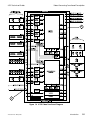
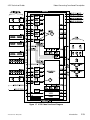
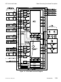
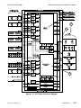
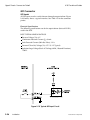
8150 Technical Guide
Engineering Menu
digital signal at the 4:4:4 sample rate for use as a chroma key source with
the optional 4:4:4 chroma keyers. This feature is automatically enabled
only when both of the following conditions are met:
At least one keyer is set as a Chroma Key in the Main submenu with
Chroma 444 selected as its Key Type in the Advanced Chroma Key
submenu.
That keyer has the odd numbered "A" input of the Component Analog
+ Key module selected as its 444 Cut Source #1. (You should also select
the even numbered "B" input of the same module as the 444 Cut Source
#2 for this feature to operate correctly; this selection is not automatic.)
With both of these conditions met, the input module changes its
sampling mode from 4:2:2 to 4:4:4 and uses the normal key path for the
extra chrominance samples. This means that, in 4:4:4 mode, a key signal
connected to the key input cannot be routed to the 8150. However,
changing either of the above conditions (selecting a different mode for
the keyer, or selecting a different 4:4:4 Cut Source #1) sets the sampling
rate of the input module back to 4:2:2 and allows the use of the key input.
The Master/Slave pushknob appears only for even numbered inputs for
which a Component Analog Input module is installed. This feature lets
analog signals without sync be connected to the even numbered "B"
input (2, 4, 6, etc.), and a companion signal with sync, such as correlated
key or composite sync, to be connected to the adjacent odd numbered
"A" input (1, 3, 5, etc.) on the same module. The default setting for this
control is Master; you should set it to Slave only if the signal connected
to the "B" input has no sync on the G or Y channel (including non
composite key signals). The "A" input must have sync on the G or Y
channel.
The Component Video + Key module contains a separate sync input that
you can use to supply separate sync without using up a dedicated video
input. The use of this separate sync input is selected with jumpers on the
circuit board of the module. See Section 3 – Option Installation for
information on jumper settings for this module.
Gain/Pedstl Offsets
This softkey accesses Y Gain, U Gain, and V Gain pushknobs (plus a
Pedestal pushknob if the selected format contains setup). Each
pushknob setting defaults to 0.00, which is set at the factory for unity
gain. A negative offset reduces the gain (or pedestal) and a positive offset
increases the gain (or pedestal) of each channel individually. There are
no red/green/blue gain adjustments when the input format is RGB, as
the gain adjustments are downstream of the RGB to YUV transcoding
matrices.
9100-0212-04 - May 2000
Engineering Setup
5-9


![User's Manual[FBD1] ProMax ProMedia Converter](http://vs1.manualzilla.com/store/data/006881326_1-9e3a0042b45fc9f5f8ff38953ecf78a2-150x150.png)