
1
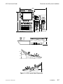
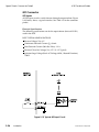
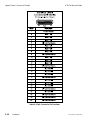
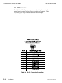
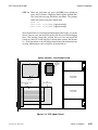
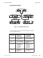
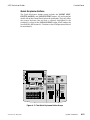
8150 Technical Guide
Assembly Removal /Replacement
STEP 4:
Unplug the two way Power Fail cable from Motherboard
connector J20.
STEP 5:
Disconnect the 3-way AC harness on the right hand side of
the power supply from the AC input harness at the rear of
the chassis.
STEP 6:
Remove the two M4 flat head screws that secure the power
supply tray to the front of the chassis.
STEP 7:
Two rear facing tabs on the bottom of the chassis locate and
secure the rear of the power supply tray. Push the power
supply tray back into the chassis slightly to clear these tabs,
and lift the rear of the tray straight up, over the tabs, and out
the front of the chassis.
STEP 8:
To remove the power supply from its tray, loosen the lugs at
the rear of the power supply and remove the DC harnesses.
The harness wires are color coded as follows:
9100-0212-04 - May 2000
Power Supply DC Terminals
Wire Color and Size
CH 1 + (+5VDC)
Red (6 awg)
CH 1 – (+5VDC return)
Black (6 awg)
CH 2 + (+12VDC)
Orange (18 awg)
CH 2 – (+12VDC return)
Orange/black (18 awg)
CH 3 + (–12VDC return)
White/black (18 awg)
CH 3 – (–12VDC)
White ( 18 awg)
CH 4 + (–5.2VDC return)
Violet/black ( 16 awg)
CH 4 – (–5.2VDC)
Violet ( 16 awg)
Engineering Setup
5-65


![User's Manual[FBD1] ProMax ProMedia Converter](http://vs1.manualzilla.com/store/data/006881326_1-9e3a0042b45fc9f5f8ff38953ecf78a2-150x150.png)