1
Agilent B1500A/B1505A
Device Analyzer Series
Programming Guide
Agilent Technologies
Notices
© Agilent Technologies, Inc. 2005 - 2013
Warranty
No part of this manual may be reproduced in
any form or by any means (including electronic storage and retrieval or translation
into a foreign language) without prior agreement and written consent from Agilent
Technologies, Inc. as governed by United
States and international copyright laws.
The material contained in this document is provided “as is,” and is subject to being changed, without notice,
in future editions. Further, to the maximum extent permitted by applicable
law, Agilent disclaims all warranties,
either express or implied, with regard
to this manual and any information
contained herein, including but not
limited to the implied warranties of
merchantability and fitness for a particular purpose. Agilent shall not be
liable for errors or for incidental or
consequential damages in connection with the furnishing, use, or performance of this document or of any
information contained herein. Should
Agilent and the user have a separate
written agreement with warranty
terms covering the material in this
document that conflict with these
terms, the warranty terms in the separate agreement shall control.
Manual Part Number
B1500-90010
Edition
Edition 1, August 2005
Edition 2, April 2006
Edition 3, June 2007
Edition 4, December 2007
Edition 5, October 2008
Edition 6, June 2009
Edition 7, November 2009
Edition 8, June 2010
Edition 9, June 2012
Edition 10, September 2012
Edition 11, June 2013
Technology Licenses
Agilent Technologies, Inc.
5301 Stevens Creek Blvd
Santa Clara, CA 95051 USA
The hardware and/or software described in
this document are furnished under a license
and may be used or copied only in accordance with the terms of such license.
Restricted Rights Legend
If software is for use in the performance of a
U.S. Government prime contract or subcontract, Software is delivered and licensed as
“Commercial computer software” as
defined in DFAR 252.227-7014 (June 1995),
or as a “commercial item” as defined in FAR
2.101(a) or as “Restricted computer software” as defined in FAR 52.227-19 (June
1987) or any equivalent agency regulation or
contract clause. Use, duplication or disclosure of Software is subject to Agilent Technologies’ standard commercial license
terms, and non-DOD Departments and
Agencies of the U.S. Government will
receive no greater than Restricted Rights as
defined in FAR 52.227-19(c)(1-2) (June
1987). U.S. Government users will receive
no greater than Limited Rights as defined in
FAR 52.227-14 (June 1987) or DFAR
252.227-7015 (b)(2) (November 1995), as
applicable in any technical data.
For B1500A Users
Agilent B1500A supports the following measurement resources. For reading this
manual, ignore the information about the other resources.
•
HPSMU High power source/monitor unit (B1510A)
•
MPSMU Medium power source/monitor unit (B1511A/B1511B)
•
MCSMU Medium current source/monitor unit (B1514A)
•
HRSMU High resolution source/monitor unit (B1517A)
•
MFCMU or CMU Multi frequency capacitance measurement unit (B1520A)
•
HVSPGU or SPGU High voltage semiconductor pulse generator unit (B1525A)
For B1505A Users
Agilent B1505A supports the following measurement resources. For reading this
manual, ignore the information about the other resources.
•
HPSMU High power source/monitor unit (B1510A)
•
MPSMU Medium power source/monitor unit (B1511A)
•
HCSMU High current source/monitor unit (B1512A)
•
MCSMU Medium current source/monitor unit (B1514A)
•
HVSMU High voltage source/monitor unit (B1513A/B1513B)
•
MFCMU or CMU Multi frequency capacitance measurement unit (B1520A)
•
HVMCU High voltage medium current unit (N1266A with one B1513B and two
B1514A/B1512A)
•
UHCU Ultra high current unit (N1265A with two B1514A/B1512A)
•
UHVU Ultra high voltage unit (N1268A with two B1514A/B1512A)
In This Manual
This manual provides the information to control the Agilent B1500 via GPIB interface
using an external computer, and consists of the following chapters.
•
“Programming Basics”
This chapter provides basic information to control the Agilent B1500.
•
“Remote Mode Functions”
This chapter explains the functions of the Agilent B1500 in the remote mode.
•
“Programming Examples”
This chapter lists the GPIB commands and explains the programming examples
for each measurement mode or function. The examples have been written in the
Microsoft Visual Basic .NET or the HP BASIC language.
•
“Command Reference”
This chapter provides the complete reference of the GPIB commands of the
Agilent B1500.
•
“Error Messages”
This chapter lists the error codes, and explains them.
Contents
1. Programming Basics
Before Starting . . . . . . . . . . . . . . . . . . . . . . . . . . . . . . . . . . . . . . . . . . . . . . . . . . . . . . . . 1-3
FlexGUI Window . . . . . . . . . . . . . . . . . . . . . . . . . . . . . . . . . . . . . . . . . . . . . . . . . . . . . 1-4
Getting Started . . . . . . . . . . . . . . . . . . . . . . . . . . . . . . . . . . . . . . . . . . . . . . . . . . . . . . . . 1-7
To Reset the Agilent B1500 . . . . . . . . . . . . . . . . . . . . . . . . . . . . . . . . . . . . . . . . . . . . 1-8
To Read Query Response . . . . . . . . . . . . . . . . . . . . . . . . . . . . . . . . . . . . . . . . . . . . . . 1-8
To Perform Self-Test . . . . . . . . . . . . . . . . . . . . . . . . . . . . . . . . . . . . . . . . . . . . . . . . . . 1-8
To Perform Self-Calibration . . . . . . . . . . . . . . . . . . . . . . . . . . . . . . . . . . . . . . . . . . . . 1-8
To Perform Diagnostics . . . . . . . . . . . . . . . . . . . . . . . . . . . . . . . . . . . . . . . . . . . . . . . 1-9
To Enable Source/Measurement Channels . . . . . . . . . . . . . . . . . . . . . . . . . . . . . . . 1-9
To Select the Measurement Mode . . . . . . . . . . . . . . . . . . . . . . . . . . . . . . . . . . . . . . 1-9
To Force Voltage/Current . . . . . . . . . . . . . . . . . . . . . . . . . . . . . . . . . . . . . . . . . . . . . 1-12
To Set the SMU Integration Time . . . . . . . . . . . . . . . . . . . . . . . . . . . . . . . . . . . . . . 1-13
To Set the Measurement Range . . . . . . . . . . . . . . . . . . . . . . . . . . . . . . . . . . . . . . . 1-14
To Pause Command Execution. . . . . . . . . . . . . . . . . . . . . . . . . . . . . . . . . . . . . . . . . 1-15
To Start Measurement . . . . . . . . . . . . . . . . . . . . . . . . . . . . . . . . . . . . . . . . . . . . . . . 1-15
To Force 0 V. . . . . . . . . . . . . . . . . . . . . . . . . . . . . . . . . . . . . . . . . . . . . . . . . . . . . . . . 1-15
To Disable Source/Measurement Channels . . . . . . . . . . . . . . . . . . . . . . . . . . . . . . 1-16
To Control ASU . . . . . . . . . . . . . . . . . . . . . . . . . . . . . . . . . . . . . . . . . . . . . . . . . . . . . 1-16
To Control SCUU . . . . . . . . . . . . . . . . . . . . . . . . . . . . . . . . . . . . . . . . . . . . . . . . . . . . 1-17
To Read Error Code/Message . . . . . . . . . . . . . . . . . . . . . . . . . . . . . . . . . . . . . . . . . 1-18
To Read Spot Measurement Data . . . . . . . . . . . . . . . . . . . . . . . . . . . . . . . . . . . . . . 1-18
To Read Sweep Measurement Data . . . . . . . . . . . . . . . . . . . . . . . . . . . . . . . . . . . . 1-19
To Read Time Stamp Data . . . . . . . . . . . . . . . . . . . . . . . . . . . . . . . . . . . . . . . . . . . . 1-20
To Perform High Speed Spot Measurement . . . . . . . . . . . . . . . . . . . . . . . . . . . . . . 1-21
Command Input Format . . . . . . . . . . . . . . . . . . . . . . . . . . . . . . . . . . . . . . . . . . . . . . . . 1-22
Header . . . . . . . . . . . . . . . . . . . . . . . . . . . . . . . . . . . . . . . . . . . . . . . . . . . . . . . . . . . . 1-22
Numeric Data . . . . . . . . . . . . . . . . . . . . . . . . . . . . . . . . . . . . . . . . . . . . . . . . . . . . . . 1-23
Terminator . . . . . . . . . . . . . . . . . . . . . . . . . . . . . . . . . . . . . . . . . . . . . . . . . . . . . . . . . 1-24
Special Terminator . . . . . . . . . . . . . . . . . . . . . . . . . . . . . . . . . . . . . . . . . . . . . . . . . . 1-24
Agilent B1500A/B1505A Programming Guide, Edition 11
Contents
Separator . . . . . . . . . . . . . . . . . . . . . . . . . . . . . . . . . . . . . . . . . . . . . . . . . . . . . . . . . . 1-24
Data Output Format . . . . . . . . . . . . . . . . . . . . . . . . . . . . . . . . . . . . . . . . . . . . . . . . . . . 1-25
Conventions. . . . . . . . . . . . . . . . . . . . . . . . . . . . . . . . . . . . . . . . . . . . . . . . . . . . . . . . 1-25
ASCII Data Output Format . . . . . . . . . . . . . . . . . . . . . . . . . . . . . . . . . . . . . . . . . . . . 1-26
Binary Data Output Format. . . . . . . . . . . . . . . . . . . . . . . . . . . . . . . . . . . . . . . . . . . . 1-36
GPIB Interface Capability . . . . . . . . . . . . . . . . . . . . . . . . . . . . . . . . . . . . . . . . . . . . . . . 1-55
Status Byte . . . . . . . . . . . . . . . . . . . . . . . . . . . . . . . . . . . . . . . . . . . . . . . . . . . . . . . . . . 1-56
Programming Tips . . . . . . . . . . . . . . . . . . . . . . . . . . . . . . . . . . . . . . . . . . . . . . . . . . . . 1-58
To Confirm the Operation . . . . . . . . . . . . . . . . . . . . . . . . . . . . . . . . . . . . . . . . . . . . . 1-59
To Confirm the Command Completion . . . . . . . . . . . . . . . . . . . . . . . . . . . . . . . . . . . 1-59
To Disable the Auto Calibration . . . . . . . . . . . . . . . . . . . . . . . . . . . . . . . . . . . . . . . . 1-59
To Optimize the Measurement Range . . . . . . . . . . . . . . . . . . . . . . . . . . . . . . . . . . . 1-60
To Optimize the Integration Time . . . . . . . . . . . . . . . . . . . . . . . . . . . . . . . . . . . . . . . 1-60
To Disable the ADC Zero Function . . . . . . . . . . . . . . . . . . . . . . . . . . . . . . . . . . . . . . 1-60
To Optimize the Source/Measurement Wait Time . . . . . . . . . . . . . . . . . . . . . . . . . 1-61
To Use the Internal Program Memory . . . . . . . . . . . . . . . . . . . . . . . . . . . . . . . . . . . 1-62
To Get Time Data with the Best Resolution . . . . . . . . . . . . . . . . . . . . . . . . . . . . . . 1-62
To Use Sweep Source as a Constant Source . . . . . . . . . . . . . . . . . . . . . . . . . . . . . 1-62
To Start Measurements Simultaneously . . . . . . . . . . . . . . . . . . . . . . . . . . . . . . . . . 1-62
To Perform Quasi-Sampling Measurement . . . . . . . . . . . . . . . . . . . . . . . . . . . . . . . 1-63
To Interrupt Command Execution. . . . . . . . . . . . . . . . . . . . . . . . . . . . . . . . . . . . . . . 1-63
To Use Programs for Agilent 4142B. . . . . . . . . . . . . . . . . . . . . . . . . . . . . . . . . . . . . 1-64
To Use Programs for Agilent 4155/4156 . . . . . . . . . . . . . . . . . . . . . . . . . . . . . . . . . 1-65
To Use Programs for Agilent E5260/E5270 . . . . . . . . . . . . . . . . . . . . . . . . . . . . . . . 1-67
2. Remote Mode Functions
Measurement Modes . . . . . . . . . . . . . . . . . . . . . . . . . . . . . . . . . . . . . . . . . . . . . . . . . . . 2-3
Spot Measurements . . . . . . . . . . . . . . . . . . . . . . . . . . . . . . . . . . . . . . . . . . . . . . . . . . 2-4
Pulsed Spot Measurements . . . . . . . . . . . . . . . . . . . . . . . . . . . . . . . . . . . . . . . . . . . . 2-5
Multi Channel Pulsed Spot Measurements . . . . . . . . . . . . . . . . . . . . . . . . . . . . . . . 2-6
Agilent B1500A/B1505A Programming Guide, Edition 11
Contents
Staircase Sweep Measurements. . . . . . . . . . . . . . . . . . . . . . . . . . . . . . . . . . . . . . . . 2-8
Staircase Sweep with Pulsed Bias Measurements . . . . . . . . . . . . . . . . . . . . . . . . 2-10
Pulsed Sweep Measurements . . . . . . . . . . . . . . . . . . . . . . . . . . . . . . . . . . . . . . . . . 2-12
Multi Channel Sweep Measurements. . . . . . . . . . . . . . . . . . . . . . . . . . . . . . . . . . . 2-14
Multi Channel Pulsed Sweep Measurements . . . . . . . . . . . . . . . . . . . . . . . . . . . . 2-16
Quasi-Pulsed Spot Measurements . . . . . . . . . . . . . . . . . . . . . . . . . . . . . . . . . . . . . 2-18
Binary Search Measurements . . . . . . . . . . . . . . . . . . . . . . . . . . . . . . . . . . . . . . . . . 2-20
Linear Search Measurements . . . . . . . . . . . . . . . . . . . . . . . . . . . . . . . . . . . . . . . . . 2-22
Sampling Measurements . . . . . . . . . . . . . . . . . . . . . . . . . . . . . . . . . . . . . . . . . . . . . 2-24
Quasi-static CV Measurements . . . . . . . . . . . . . . . . . . . . . . . . . . . . . . . . . . . . . . . . 2-27
Spot C Measurements . . . . . . . . . . . . . . . . . . . . . . . . . . . . . . . . . . . . . . . . . . . . . . . 2-30
Pulsed Spot C Measurements . . . . . . . . . . . . . . . . . . . . . . . . . . . . . . . . . . . . . . . . . 2-31
CV (DC bias) Sweep Measurements . . . . . . . . . . . . . . . . . . . . . . . . . . . . . . . . . . . . 2-33
Pulsed Sweep CV Measurements . . . . . . . . . . . . . . . . . . . . . . . . . . . . . . . . . . . . . . 2-36
C-f Sweep Measurements . . . . . . . . . . . . . . . . . . . . . . . . . . . . . . . . . . . . . . . . . . . . 2-38
CV (AC level) Sweep Measurements . . . . . . . . . . . . . . . . . . . . . . . . . . . . . . . . . . . 2-40
C-t Sampling Measurements . . . . . . . . . . . . . . . . . . . . . . . . . . . . . . . . . . . . . . . . . . 2-42
Synchronous Output. . . . . . . . . . . . . . . . . . . . . . . . . . . . . . . . . . . . . . . . . . . . . . . . . . . 2-44
Automatic Abort Function . . . . . . . . . . . . . . . . . . . . . . . . . . . . . . . . . . . . . . . . . . . . . . 2-46
Parallel Measurement Function. . . . . . . . . . . . . . . . . . . . . . . . . . . . . . . . . . . . . . . . . . 2-48
Required Conditions . . . . . . . . . . . . . . . . . . . . . . . . . . . . . . . . . . . . . . . . . . . . . . . . . 2-48
Program Memory . . . . . . . . . . . . . . . . . . . . . . . . . . . . . . . . . . . . . . . . . . . . . . . . . . . . . 2-49
Using Program Memory . . . . . . . . . . . . . . . . . . . . . . . . . . . . . . . . . . . . . . . . . . . . . . 2-49
Dual HCSMU . . . . . . . . . . . . . . . . . . . . . . . . . . . . . . . . . . . . . . . . . . . . . . . . . . . . . . . . . 2-52
SPGU Module . . . . . . . . . . . . . . . . . . . . . . . . . . . . . . . . . . . . . . . . . . . . . . . . . . . . . . . . 2-53
PG Operation Mode . . . . . . . . . . . . . . . . . . . . . . . . . . . . . . . . . . . . . . . . . . . . . . . . . 2-55
ALWG Operation Mode . . . . . . . . . . . . . . . . . . . . . . . . . . . . . . . . . . . . . . . . . . . . . . 2-59
Module Selector . . . . . . . . . . . . . . . . . . . . . . . . . . . . . . . . . . . . . . . . . . . . . . . . . . . . . . 2-64
External Relay Control Output . . . . . . . . . . . . . . . . . . . . . . . . . . . . . . . . . . . . . . . . . 2-65
Agilent B1500A/B1505A Programming Guide, Edition 11
Contents
SMU/PG Selector . . . . . . . . . . . . . . . . . . . . . . . . . . . . . . . . . . . . . . . . . . . . . . . . . . . . . 2-66
Ultra High Current Expander/Fixture. . . . . . . . . . . . . . . . . . . . . . . . . . . . . . . . . . . . . . 2-67
HVSMU Current Expander . . . . . . . . . . . . . . . . . . . . . . . . . . . . . . . . . . . . . . . . . . . . . . 2-69
Ultra High Voltage Expander . . . . . . . . . . . . . . . . . . . . . . . . . . . . . . . . . . . . . . . . . . . . 2-70
Digital I/O Port . . . . . . . . . . . . . . . . . . . . . . . . . . . . . . . . . . . . . . . . . . . . . . . . . . . . . . . 2-71
Accessories . . . . . . . . . . . . . . . . . . . . . . . . . . . . . . . . . . . . . . . . . . . . . . . . . . . . . . . . 2-72
Digital I/O Internal Circuit . . . . . . . . . . . . . . . . . . . . . . . . . . . . . . . . . . . . . . . . . . . . 2-73
Trigger Function . . . . . . . . . . . . . . . . . . . . . . . . . . . . . . . . . . . . . . . . . . . . . . . . . . . . . . 2-74
Trigger Input . . . . . . . . . . . . . . . . . . . . . . . . . . . . . . . . . . . . . . . . . . . . . . . . . . . . . . . 2-75
Trigger Output . . . . . . . . . . . . . . . . . . . . . . . . . . . . . . . . . . . . . . . . . . . . . . . . . . . . . . 2-77
Using Trigger Function . . . . . . . . . . . . . . . . . . . . . . . . . . . . . . . . . . . . . . . . . . . . . . . 2-80
Trig In/Out Internal Circuit . . . . . . . . . . . . . . . . . . . . . . . . . . . . . . . . . . . . . . . . . . . . 2-86
Initial Settings . . . . . . . . . . . . . . . . . . . . . . . . . . . . . . . . . . . . . . . . . . . . . . . . . . . . . . . 2-87
3. Programming Examples
Programming Basics for Visual Basic .NET Users . . . . . . . . . . . . . . . . . . . . . . . . . . . . 3-4
To Create Your Project Template . . . . . . . . . . . . . . . . . . . . . . . . . . . . . . . . . . . . . . . . 3-4
To Create Measurement Program . . . . . . . . . . . . . . . . . . . . . . . . . . . . . . . . . . . . . . . 3-5
High-Speed Spot Measurements . . . . . . . . . . . . . . . . . . . . . . . . . . . . . . . . . . . . . . . . . . 3-9
Spot Measurements . . . . . . . . . . . . . . . . . . . . . . . . . . . . . . . . . . . . . . . . . . . . . . . . . . 3-12
Pulsed Spot Measurements . . . . . . . . . . . . . . . . . . . . . . . . . . . . . . . . . . . . . . . . . . . . 3-15
Staircase Sweep Measurements . . . . . . . . . . . . . . . . . . . . . . . . . . . . . . . . . . . . . . . . 3-18
Pulsed Sweep Measurements . . . . . . . . . . . . . . . . . . . . . . . . . . . . . . . . . . . . . . . . . . 3-28
Staircase Sweep with Pulsed Bias Measurements . . . . . . . . . . . . . . . . . . . . . . . . . . 3-32
Quasi Pulsed Spot Measurements . . . . . . . . . . . . . . . . . . . . . . . . . . . . . . . . . . . . . . . 3-36
Linear Search Measurements . . . . . . . . . . . . . . . . . . . . . . . . . . . . . . . . . . . . . . . . . . . 3-39
Agilent B1500A/B1505A Programming Guide, Edition 11
Contents
Binary Search Measurements . . . . . . . . . . . . . . . . . . . . . . . . . . . . . . . . . . . . . . . . . . . 3-42
Multi Channel Sweep Measurements. . . . . . . . . . . . . . . . . . . . . . . . . . . . . . . . . . . . . 3-45
Multi Channel Pulsed Spot Measurements . . . . . . . . . . . . . . . . . . . . . . . . . . . . . . . . 3-49
Multi Channel Pulsed Sweep Measurements . . . . . . . . . . . . . . . . . . . . . . . . . . . . . . 3-52
Sampling Measurements . . . . . . . . . . . . . . . . . . . . . . . . . . . . . . . . . . . . . . . . . . . . . . 3-56
Quasi-static CV Measurements . . . . . . . . . . . . . . . . . . . . . . . . . . . . . . . . . . . . . . . . . . 3-61
High-Speed Spot C Measurements . . . . . . . . . . . . . . . . . . . . . . . . . . . . . . . . . . . . . . . 3-66
Spot C Measurements . . . . . . . . . . . . . . . . . . . . . . . . . . . . . . . . . . . . . . . . . . . . . . . . . 3-72
CV (DC Bias) Sweep Measurements. . . . . . . . . . . . . . . . . . . . . . . . . . . . . . . . . . . . . . 3-76
Pulsed Spot C Measurements . . . . . . . . . . . . . . . . . . . . . . . . . . . . . . . . . . . . . . . . . . . 3-81
Pulsed Sweep CV Measurements . . . . . . . . . . . . . . . . . . . . . . . . . . . . . . . . . . . . . . . . 3-85
CV (AC Level) Sweep Measurements . . . . . . . . . . . . . . . . . . . . . . . . . . . . . . . . . . . . . 3-90
C-f Sweep Measurements . . . . . . . . . . . . . . . . . . . . . . . . . . . . . . . . . . . . . . . . . . . . . . 3-95
C-t Sampling Measurements . . . . . . . . . . . . . . . . . . . . . . . . . . . . . . . . . . . . . . . . . . . 3-100
SPGU Pulse Output and Voltage Measurement . . . . . . . . . . . . . . . . . . . . . . . . . . . . 3-105
Using Program Memory . . . . . . . . . . . . . . . . . . . . . . . . . . . . . . . . . . . . . . . . . . . . . . 3-112
Tips to use program memory . . . . . . . . . . . . . . . . . . . . . . . . . . . . . . . . . . . . . . . . . 3-113
Using Trigger Function . . . . . . . . . . . . . . . . . . . . . . . . . . . . . . . . . . . . . . . . . . . . . . . . 3-118
Reading Time Stamp Data . . . . . . . . . . . . . . . . . . . . . . . . . . . . . . . . . . . . . . . . . . . . . 3-130
Reading Binary Output Data . . . . . . . . . . . . . . . . . . . . . . . . . . . . . . . . . . . . . . . . . . . 3-131
Using Programs for 4142B . . . . . . . . . . . . . . . . . . . . . . . . . . . . . . . . . . . . . . . . . . . . . 3-134
Using Programs for 4155B/4156B/4155C/4156C . . . . . . . . . . . . . . . . . . . . . . . . . . 3-136
4. Command Reference
Agilent B1500A/B1505A Programming Guide, Edition 11
Contents
Command Summary . . . . . . . . . . . . . . . . . . . . . . . . . . . . . . . . . . . . . . . . . . . . . . . . . . . . 4-3
Command Parameters . . . . . . . . . . . . . . . . . . . . . . . . . . . . . . . . . . . . . . . . . . . . . . . . . 4-15
Command Reference . . . . . . . . . . . . . . . . . . . . . . . . . . . . . . . . . . . . . . . . . . . . . . . . . . 4-32
AAD . . . . . . . . . . . . . . . . . . . . . . . . . . . . . . . . . . . . . . . . . . . . . . . . . . . . . . . . . . . . . . 4-33
AB . . . . . . . . . . . . . . . . . . . . . . . . . . . . . . . . . . . . . . . . . . . . . . . . . . . . . . . . . . . . . . . 4-33
ACH . . . . . . . . . . . . . . . . . . . . . . . . . . . . . . . . . . . . . . . . . . . . . . . . . . . . . . . . . . . . . . 4-35
ACT . . . . . . . . . . . . . . . . . . . . . . . . . . . . . . . . . . . . . . . . . . . . . . . . . . . . . . . . . . . . . . 4-36
ACV . . . . . . . . . . . . . . . . . . . . . . . . . . . . . . . . . . . . . . . . . . . . . . . . . . . . . . . . . . . . . . 4-36
ADJ . . . . . . . . . . . . . . . . . . . . . . . . . . . . . . . . . . . . . . . . . . . . . . . . . . . . . . . . . . . . . . 4-37
ADJ?. . . . . . . . . . . . . . . . . . . . . . . . . . . . . . . . . . . . . . . . . . . . . . . . . . . . . . . . . . . . . . 4-37
AIT . . . . . . . . . . . . . . . . . . . . . . . . . . . . . . . . . . . . . . . . . . . . . . . . . . . . . . . . . . . . . . . 4-38
AITM . . . . . . . . . . . . . . . . . . . . . . . . . . . . . . . . . . . . . . . . . . . . . . . . . . . . . . . . . . . . . 4-41
AITM? . . . . . . . . . . . . . . . . . . . . . . . . . . . . . . . . . . . . . . . . . . . . . . . . . . . . . . . . . . . . 4-41
ALS. . . . . . . . . . . . . . . . . . . . . . . . . . . . . . . . . . . . . . . . . . . . . . . . . . . . . . . . . . . . . . . 4-41
ALS? . . . . . . . . . . . . . . . . . . . . . . . . . . . . . . . . . . . . . . . . . . . . . . . . . . . . . . . . . . . . . . 4-42
ALW . . . . . . . . . . . . . . . . . . . . . . . . . . . . . . . . . . . . . . . . . . . . . . . . . . . . . . . . . . . . . . 4-42
ALW? . . . . . . . . . . . . . . . . . . . . . . . . . . . . . . . . . . . . . . . . . . . . . . . . . . . . . . . . . . . . . 4-43
AV. . . . . . . . . . . . . . . . . . . . . . . . . . . . . . . . . . . . . . . . . . . . . . . . . . . . . . . . . . . . . . . . 4-43
AZ . . . . . . . . . . . . . . . . . . . . . . . . . . . . . . . . . . . . . . . . . . . . . . . . . . . . . . . . . . . . . . . 4-44
BC . . . . . . . . . . . . . . . . . . . . . . . . . . . . . . . . . . . . . . . . . . . . . . . . . . . . . . . . . . . . . . . 4-45
BDM. . . . . . . . . . . . . . . . . . . . . . . . . . . . . . . . . . . . . . . . . . . . . . . . . . . . . . . . . . . . . . 4-45
BDT . . . . . . . . . . . . . . . . . . . . . . . . . . . . . . . . . . . . . . . . . . . . . . . . . . . . . . . . . . . . . . 4-46
BDV . . . . . . . . . . . . . . . . . . . . . . . . . . . . . . . . . . . . . . . . . . . . . . . . . . . . . . . . . . . . . . 4-46
BGI . . . . . . . . . . . . . . . . . . . . . . . . . . . . . . . . . . . . . . . . . . . . . . . . . . . . . . . . . . . . . . . 4-47
BGV . . . . . . . . . . . . . . . . . . . . . . . . . . . . . . . . . . . . . . . . . . . . . . . . . . . . . . . . . . . . . . 4-48
BSI . . . . . . . . . . . . . . . . . . . . . . . . . . . . . . . . . . . . . . . . . . . . . . . . . . . . . . . . . . . . . . . 4-50
BSM . . . . . . . . . . . . . . . . . . . . . . . . . . . . . . . . . . . . . . . . . . . . . . . . . . . . . . . . . . . . . . 4-51
BSSI . . . . . . . . . . . . . . . . . . . . . . . . . . . . . . . . . . . . . . . . . . . . . . . . . . . . . . . . . . . . . 4-53
BSSV . . . . . . . . . . . . . . . . . . . . . . . . . . . . . . . . . . . . . . . . . . . . . . . . . . . . . . . . . . . . . 4-54
BST. . . . . . . . . . . . . . . . . . . . . . . . . . . . . . . . . . . . . . . . . . . . . . . . . . . . . . . . . . . . . . . 4-55
BSV . . . . . . . . . . . . . . . . . . . . . . . . . . . . . . . . . . . . . . . . . . . . . . . . . . . . . . . . . . . . . . 4-55
Agilent B1500A/B1505A Programming Guide, Edition 11
Contents
BSVM . . . . . . . . . . . . . . . . . . . . . . . . . . . . . . . . . . . . . . . . . . . . . . . . . . . . . . . . . . . . 4-56
CA . . . . . . . . . . . . . . . . . . . . . . . . . . . . . . . . . . . . . . . . . . . . . . . . . . . . . . . . . . . . . . . 4-56
*CAL? . . . . . . . . . . . . . . . . . . . . . . . . . . . . . . . . . . . . . . . . . . . . . . . . . . . . . . . . . . . . 4-57
CL . . . . . . . . . . . . . . . . . . . . . . . . . . . . . . . . . . . . . . . . . . . . . . . . . . . . . . . . . . . . . . . 4-59
CLCORR . . . . . . . . . . . . . . . . . . . . . . . . . . . . . . . . . . . . . . . . . . . . . . . . . . . . . . . . . . . 4-60
CM . . . . . . . . . . . . . . . . . . . . . . . . . . . . . . . . . . . . . . . . . . . . . . . . . . . . . . . . . . . . . . 4-60
CMM . . . . . . . . . . . . . . . . . . . . . . . . . . . . . . . . . . . . . . . . . . . . . . . . . . . . . . . . . . . . . 4-61
CN/CNX . . . . . . . . . . . . . . . . . . . . . . . . . . . . . . . . . . . . . . . . . . . . . . . . . . . . . . . . . . 4-61
CORR? . . . . . . . . . . . . . . . . . . . . . . . . . . . . . . . . . . . . . . . . . . . . . . . . . . . . . . . . . . . . 4-63
CORRDT . . . . . . . . . . . . . . . . . . . . . . . . . . . . . . . . . . . . . . . . . . . . . . . . . . . . . . . . . . . 4-64
CORRDT? . . . . . . . . . . . . . . . . . . . . . . . . . . . . . . . . . . . . . . . . . . . . . . . . . . . . . . . . . . 4-65
CORRL . . . . . . . . . . . . . . . . . . . . . . . . . . . . . . . . . . . . . . . . . . . . . . . . . . . . . . . . . . . . 4-65
CORRL? . . . . . . . . . . . . . . . . . . . . . . . . . . . . . . . . . . . . . . . . . . . . . . . . . . . . . . . . . . . 4-66
CORRSER? . . . . . . . . . . . . . . . . . . . . . . . . . . . . . . . . . . . . . . . . . . . . . . . . . . . . . . . . . 4-66
CORRST . . . . . . . . . . . . . . . . . . . . . . . . . . . . . . . . . . . . . . . . . . . . . . . . . . . . . . . . . . . 4-68
CORRST? . . . . . . . . . . . . . . . . . . . . . . . . . . . . . . . . . . . . . . . . . . . . . . . . . . . . . . . . . . 4-69
DCORR . . . . . . . . . . . . . . . . . . . . . . . . . . . . . . . . . . . . . . . . . . . . . . . . . . . . . . . . . . . . 4-70
DCORR? . . . . . . . . . . . . . . . . . . . . . . . . . . . . . . . . . . . . . . . . . . . . . . . . . . . . . . . . . . . 4-70
DCV . . . . . . . . . . . . . . . . . . . . . . . . . . . . . . . . . . . . . . . . . . . . . . . . . . . . . . . . . . . . . . 4-71
DI . . . . . . . . . . . . . . . . . . . . . . . . . . . . . . . . . . . . . . . . . . . . . . . . . . . . . . . . . . . . . . . . 4-72
DIAG? . . . . . . . . . . . . . . . . . . . . . . . . . . . . . . . . . . . . . . . . . . . . . . . . . . . . . . . . . . . . 4-73
DO . . . . . . . . . . . . . . . . . . . . . . . . . . . . . . . . . . . . . . . . . . . . . . . . . . . . . . . . . . . . . . . 4-74
DSMPLARM . . . . . . . . . . . . . . . . . . . . . . . . . . . . . . . . . . . . . . . . . . . . . . . . . . . . . . . 4-74
DSMPLFLUSH . . . . . . . . . . . . . . . . . . . . . . . . . . . . . . . . . . . . . . . . . . . . . . . . . . . . . . 4-75
DSMPLSETUP . . . . . . . . . . . . . . . . . . . . . . . . . . . . . . . . . . . . . . . . . . . . . . . . . . . . . 4-76
DV . . . . . . . . . . . . . . . . . . . . . . . . . . . . . . . . . . . . . . . . . . . . . . . . . . . . . . . . . . . . . . . 4-76
DZ . . . . . . . . . . . . . . . . . . . . . . . . . . . . . . . . . . . . . . . . . . . . . . . . . . . . . . . . . . . . . . . 4-77
EMG? . . . . . . . . . . . . . . . . . . . . . . . . . . . . . . . . . . . . . . . . . . . . . . . . . . . . . . . . . . . . . 4-78
END . . . . . . . . . . . . . . . . . . . . . . . . . . . . . . . . . . . . . . . . . . . . . . . . . . . . . . . . . . . . . . 4-79
ERC . . . . . . . . . . . . . . . . . . . . . . . . . . . . . . . . . . . . . . . . . . . . . . . . . . . . . . . . . . . . . . 4-79
ERHPA . . . . . . . . . . . . . . . . . . . . . . . . . . . . . . . . . . . . . . . . . . . . . . . . . . . . . . . . . . . . 4-80
ERHPA? . . . . . . . . . . . . . . . . . . . . . . . . . . . . . . . . . . . . . . . . . . . . . . . . . . . . . . . . . . . 4-81
Agilent B1500A/B1505A Programming Guide, Edition 11
Contents
ERHPE . . . . . . . . . . . . . . . . . . . . . . . . . . . . . . . . . . . . . . . . . . . . . . . . . . . . . . . . . . . . 4-81
ERHPE? . . . . . . . . . . . . . . . . . . . . . . . . . . . . . . . . . . . . . . . . . . . . . . . . . . . . . . . . . . . 4-81
ERHPL . . . . . . . . . . . . . . . . . . . . . . . . . . . . . . . . . . . . . . . . . . . . . . . . . . . . . . . . . . . . 4-82
ERHPL? . . . . . . . . . . . . . . . . . . . . . . . . . . . . . . . . . . . . . . . . . . . . . . . . . . . . . . . . . . . 4-82
ERHPP . . . . . . . . . . . . . . . . . . . . . . . . . . . . . . . . . . . . . . . . . . . . . . . . . . . . . . . . . . . . 4-82
ERHPP? . . . . . . . . . . . . . . . . . . . . . . . . . . . . . . . . . . . . . . . . . . . . . . . . . . . . . . . . . . . 4-83
ERHPR . . . . . . . . . . . . . . . . . . . . . . . . . . . . . . . . . . . . . . . . . . . . . . . . . . . . . . . . . . . . 4-83
ERHPR? . . . . . . . . . . . . . . . . . . . . . . . . . . . . . . . . . . . . . . . . . . . . . . . . . . . . . . . . . . . 4-84
ERHPS . . . . . . . . . . . . . . . . . . . . . . . . . . . . . . . . . . . . . . . . . . . . . . . . . . . . . . . . . . . . 4-84
ERHPS? . . . . . . . . . . . . . . . . . . . . . . . . . . . . . . . . . . . . . . . . . . . . . . . . . . . . . . . . . . . 4-85
ERHVCA . . . . . . . . . . . . . . . . . . . . . . . . . . . . . . . . . . . . . . . . . . . . . . . . . . . . . . . . . . . 4-85
ERHVCA? . . . . . . . . . . . . . . . . . . . . . . . . . . . . . . . . . . . . . . . . . . . . . . . . . . . . . . . . . . 4-86
ERHVCTST? . . . . . . . . . . . . . . . . . . . . . . . . . . . . . . . . . . . . . . . . . . . . . . . . . . . . . . . . 4-86
ERHVP . . . . . . . . . . . . . . . . . . . . . . . . . . . . . . . . . . . . . . . . . . . . . . . . . . . . . . . . . . . . 4-86
ERHVP? . . . . . . . . . . . . . . . . . . . . . . . . . . . . . . . . . . . . . . . . . . . . . . . . . . . . . . . . . . . 4-87
ERHVPV . . . . . . . . . . . . . . . . . . . . . . . . . . . . . . . . . . . . . . . . . . . . . . . . . . . . . . . . . . . 4-87
ERHVS . . . . . . . . . . . . . . . . . . . . . . . . . . . . . . . . . . . . . . . . . . . . . . . . . . . . . . . . . . . . 4-88
ERHVS? . . . . . . . . . . . . . . . . . . . . . . . . . . . . . . . . . . . . . . . . . . . . . . . . . . . . . . . . . . . 4-88
ERM . . . . . . . . . . . . . . . . . . . . . . . . . . . . . . . . . . . . . . . . . . . . . . . . . . . . . . . . . . . . . . 4-89
ERMOD . . . . . . . . . . . . . . . . . . . . . . . . . . . . . . . . . . . . . . . . . . . . . . . . . . . . . . . . . . . 4-89
ERMOD?. . . . . . . . . . . . . . . . . . . . . . . . . . . . . . . . . . . . . . . . . . . . . . . . . . . . . . . . . . . 4-91
ERPFDA . . . . . . . . . . . . . . . . . . . . . . . . . . . . . . . . . . . . . . . . . . . . . . . . . . . . . . . . . . . 4-91
ERPFDA? . . . . . . . . . . . . . . . . . . . . . . . . . . . . . . . . . . . . . . . . . . . . . . . . . . . . . . . . . . 4-92
ERPFDP . . . . . . . . . . . . . . . . . . . . . . . . . . . . . . . . . . . . . . . . . . . . . . . . . . . . . . . . . . . 4-92
ERPFDP? . . . . . . . . . . . . . . . . . . . . . . . . . . . . . . . . . . . . . . . . . . . . . . . . . . . . . . . . . . 4-93
ERPFDS . . . . . . . . . . . . . . . . . . . . . . . . . . . . . . . . . . . . . . . . . . . . . . . . . . . . . . . . . . . 4-93
ERPFDS? . . . . . . . . . . . . . . . . . . . . . . . . . . . . . . . . . . . . . . . . . . . . . . . . . . . . . . . . . . 4-94
ERPFGA . . . . . . . . . . . . . . . . . . . . . . . . . . . . . . . . . . . . . . . . . . . . . . . . . . . . . . . . . . . 4-94
ERPFGA? . . . . . . . . . . . . . . . . . . . . . . . . . . . . . . . . . . . . . . . . . . . . . . . . . . . . . . . . . . 4-95
ERPFGP . . . . . . . . . . . . . . . . . . . . . . . . . . . . . . . . . . . . . . . . . . . . . . . . . . . . . . . . . . . 4-95
ERPFGP? . . . . . . . . . . . . . . . . . . . . . . . . . . . . . . . . . . . . . . . . . . . . . . . . . . . . . . . . . . 4-95
ERPFGR . . . . . . . . . . . . . . . . . . . . . . . . . . . . . . . . . . . . . . . . . . . . . . . . . . . . . . . . . . . 4-96
Agilent B1500A/B1505A Programming Guide, Edition 11
Contents
ERPFGR? . . . . . . . . . . . . . . . . . . . . . . . . . . . . . . . . . . . . . . . . . . . . . . . . . . . . . . . . . . 4-96
ERPFTEMP? . . . . . . . . . . . . . . . . . . . . . . . . . . . . . . . . . . . . . . . . . . . . . . . . . . . . . . . . 4-97
ERPFUHCA . . . . . . . . . . . . . . . . . . . . . . . . . . . . . . . . . . . . . . . . . . . . . . . . . . . . . . . . 4-97
ERPFUHCA?. . . . . . . . . . . . . . . . . . . . . . . . . . . . . . . . . . . . . . . . . . . . . . . . . . . . . . . . 4-98
ERPFUHCCAL? . . . . . . . . . . . . . . . . . . . . . . . . . . . . . . . . . . . . . . . . . . . . . . . . . . . . . 4-98
ERPFUHCMAX?. . . . . . . . . . . . . . . . . . . . . . . . . . . . . . . . . . . . . . . . . . . . . . . . . . . . . 4-98
ERPFUHCTST?. . . . . . . . . . . . . . . . . . . . . . . . . . . . . . . . . . . . . . . . . . . . . . . . . . . . . . 4-99
ERR? . . . . . . . . . . . . . . . . . . . . . . . . . . . . . . . . . . . . . . . . . . . . . . . . . . . . . . . . . . . . . 4-99
ERRX? . . . . . . . . . . . . . . . . . . . . . . . . . . . . . . . . . . . . . . . . . . . . . . . . . . . . . . . . . . . 4-100
ERS?. . . . . . . . . . . . . . . . . . . . . . . . . . . . . . . . . . . . . . . . . . . . . . . . . . . . . . . . . . . . . 4-101
ERSSP . . . . . . . . . . . . . . . . . . . . . . . . . . . . . . . . . . . . . . . . . . . . . . . . . . . . . . . . . . . 4-102
ERSSP? . . . . . . . . . . . . . . . . . . . . . . . . . . . . . . . . . . . . . . . . . . . . . . . . . . . . . . . . . . 4-103
ERUHVA. . . . . . . . . . . . . . . . . . . . . . . . . . . . . . . . . . . . . . . . . . . . . . . . . . . . . . . . . . 4-103
ERUHVA? . . . . . . . . . . . . . . . . . . . . . . . . . . . . . . . . . . . . . . . . . . . . . . . . . . . . . . . . . 4-104
FC . . . . . . . . . . . . . . . . . . . . . . . . . . . . . . . . . . . . . . . . . . . . . . . . . . . . . . . . . . . . . . . 4-104
FL . . . . . . . . . . . . . . . . . . . . . . . . . . . . . . . . . . . . . . . . . . . . . . . . . . . . . . . . . . . . . . 4-105
FMT . . . . . . . . . . . . . . . . . . . . . . . . . . . . . . . . . . . . . . . . . . . . . . . . . . . . . . . . . . . . . 4-105
*IDN? . . . . . . . . . . . . . . . . . . . . . . . . . . . . . . . . . . . . . . . . . . . . . . . . . . . . . . . . . . . 4-107
IMP . . . . . . . . . . . . . . . . . . . . . . . . . . . . . . . . . . . . . . . . . . . . . . . . . . . . . . . . . . . . . 4-107
IN . . . . . . . . . . . . . . . . . . . . . . . . . . . . . . . . . . . . . . . . . . . . . . . . . . . . . . . . . . . . . . 4-108
INTLKVTH . . . . . . . . . . . . . . . . . . . . . . . . . . . . . . . . . . . . . . . . . . . . . . . . . . . . . . . . 4-109
INTLKVTH? . . . . . . . . . . . . . . . . . . . . . . . . . . . . . . . . . . . . . . . . . . . . . . . . . . . . . . . 4-109
LGI . . . . . . . . . . . . . . . . . . . . . . . . . . . . . . . . . . . . . . . . . . . . . . . . . . . . . . . . . . . . . . 4-110
LGV . . . . . . . . . . . . . . . . . . . . . . . . . . . . . . . . . . . . . . . . . . . . . . . . . . . . . . . . . . . . . 4-110
LIM. . . . . . . . . . . . . . . . . . . . . . . . . . . . . . . . . . . . . . . . . . . . . . . . . . . . . . . . . . . . . . 4-111
LIM? . . . . . . . . . . . . . . . . . . . . . . . . . . . . . . . . . . . . . . . . . . . . . . . . . . . . . . . . . . . . . 4-112
LMN . . . . . . . . . . . . . . . . . . . . . . . . . . . . . . . . . . . . . . . . . . . . . . . . . . . . . . . . . . . . . 4-112
LOP? . . . . . . . . . . . . . . . . . . . . . . . . . . . . . . . . . . . . . . . . . . . . . . . . . . . . . . . . . . . . 4-112
*LRN? . . . . . . . . . . . . . . . . . . . . . . . . . . . . . . . . . . . . . . . . . . . . . . . . . . . . . . . . . . . 4-114
LSI . . . . . . . . . . . . . . . . . . . . . . . . . . . . . . . . . . . . . . . . . . . . . . . . . . . . . . . . . . . . . . 4-120
LSM . . . . . . . . . . . . . . . . . . . . . . . . . . . . . . . . . . . . . . . . . . . . . . . . . . . . . . . . . . . . . 4-121
LSSI . . . . . . . . . . . . . . . . . . . . . . . . . . . . . . . . . . . . . . . . . . . . . . . . . . . . . . . . . . . . . 4-122
Agilent B1500A/B1505A Programming Guide, Edition 11
Contents
LSSV . . . . . . . . . . . . . . . . . . . . . . . . . . . . . . . . . . . . . . . . . . . . . . . . . . . . . . . . . . . . 4-123
LST? . . . . . . . . . . . . . . . . . . . . . . . . . . . . . . . . . . . . . . . . . . . . . . . . . . . . . . . . . . . . 4-124
LSTM . . . . . . . . . . . . . . . . . . . . . . . . . . . . . . . . . . . . . . . . . . . . . . . . . . . . . . . . . . . . 4-125
LSV . . . . . . . . . . . . . . . . . . . . . . . . . . . . . . . . . . . . . . . . . . . . . . . . . . . . . . . . . . . . . 4-126
LSVM . . . . . . . . . . . . . . . . . . . . . . . . . . . . . . . . . . . . . . . . . . . . . . . . . . . . . . . . . . . . 4-127
MCC . . . . . . . . . . . . . . . . . . . . . . . . . . . . . . . . . . . . . . . . . . . . . . . . . . . . . . . . . . . . 4-127
MCPNT . . . . . . . . . . . . . . . . . . . . . . . . . . . . . . . . . . . . . . . . . . . . . . . . . . . . . . . . . . 4-128
MCPNX . . . . . . . . . . . . . . . . . . . . . . . . . . . . . . . . . . . . . . . . . . . . . . . . . . . . . . . . . . 4-129
MCPT . . . . . . . . . . . . . . . . . . . . . . . . . . . . . . . . . . . . . . . . . . . . . . . . . . . . . . . . . . . 4-130
MCPWS . . . . . . . . . . . . . . . . . . . . . . . . . . . . . . . . . . . . . . . . . . . . . . . . . . . . . . . . . 4-131
MCPWNX . . . . . . . . . . . . . . . . . . . . . . . . . . . . . . . . . . . . . . . . . . . . . . . . . . . . . . . . 4-132
MDCV. . . . . . . . . . . . . . . . . . . . . . . . . . . . . . . . . . . . . . . . . . . . . . . . . . . . . . . . . . . . 4-134
MI . . . . . . . . . . . . . . . . . . . . . . . . . . . . . . . . . . . . . . . . . . . . . . . . . . . . . . . . . . . . . . 4-135
ML . . . . . . . . . . . . . . . . . . . . . . . . . . . . . . . . . . . . . . . . . . . . . . . . . . . . . . . . . . . . . . 4-136
MM . . . . . . . . . . . . . . . . . . . . . . . . . . . . . . . . . . . . . . . . . . . . . . . . . . . . . . . . . . . . . 4-136
MSC . . . . . . . . . . . . . . . . . . . . . . . . . . . . . . . . . . . . . . . . . . . . . . . . . . . . . . . . . . . . 4-139
MSP . . . . . . . . . . . . . . . . . . . . . . . . . . . . . . . . . . . . . . . . . . . . . . . . . . . . . . . . . . . . 4-140
MT . . . . . . . . . . . . . . . . . . . . . . . . . . . . . . . . . . . . . . . . . . . . . . . . . . . . . . . . . . . . . . 4-141
MTDCV . . . . . . . . . . . . . . . . . . . . . . . . . . . . . . . . . . . . . . . . . . . . . . . . . . . . . . . . . . 4-143
MV . . . . . . . . . . . . . . . . . . . . . . . . . . . . . . . . . . . . . . . . . . . . . . . . . . . . . . . . . . . . . . 4-143
NUB? . . . . . . . . . . . . . . . . . . . . . . . . . . . . . . . . . . . . . . . . . . . . . . . . . . . . . . . . . . . . 4-144
ODSW . . . . . . . . . . . . . . . . . . . . . . . . . . . . . . . . . . . . . . . . . . . . . . . . . . . . . . . . . . . 4-144
ODSW?. . . . . . . . . . . . . . . . . . . . . . . . . . . . . . . . . . . . . . . . . . . . . . . . . . . . . . . . . . . 4-145
*OPC? . . . . . . . . . . . . . . . . . . . . . . . . . . . . . . . . . . . . . . . . . . . . . . . . . . . . . . . . . . . . 4-146
OS . . . . . . . . . . . . . . . . . . . . . . . . . . . . . . . . . . . . . . . . . . . . . . . . . . . . . . . . . . . . . . 4-146
OSX . . . . . . . . . . . . . . . . . . . . . . . . . . . . . . . . . . . . . . . . . . . . . . . . . . . . . . . . . . . . . 4-146
PA . . . . . . . . . . . . . . . . . . . . . . . . . . . . . . . . . . . . . . . . . . . . . . . . . . . . . . . . . . . . . . 4-147
PAD . . . . . . . . . . . . . . . . . . . . . . . . . . . . . . . . . . . . . . . . . . . . . . . . . . . . . . . . . . . . . 4-148
PAX . . . . . . . . . . . . . . . . . . . . . . . . . . . . . . . . . . . . . . . . . . . . . . . . . . . . . . . . . . . . . 4-148
PCH . . . . . . . . . . . . . . . . . . . . . . . . . . . . . . . . . . . . . . . . . . . . . . . . . . . . . . . . . . . . . 4-149
PCH?. . . . . . . . . . . . . . . . . . . . . . . . . . . . . . . . . . . . . . . . . . . . . . . . . . . . . . . . . . . . . 4-150
PDCV . . . . . . . . . . . . . . . . . . . . . . . . . . . . . . . . . . . . . . . . . . . . . . . . . . . . . . . . . . . . 4-150
Agilent B1500A/B1505A Programming Guide, Edition 11
Contents
PI . . . . . . . . . . . . . . . . . . . . . . . . . . . . . . . . . . . . . . . . . . . . . . . . . . . . . . . . . . . . . . . 4-151
PT . . . . . . . . . . . . . . . . . . . . . . . . . . . . . . . . . . . . . . . . . . . . . . . . . . . . . . . . . . . . . . 4-152
PTDCV . . . . . . . . . . . . . . . . . . . . . . . . . . . . . . . . . . . . . . . . . . . . . . . . . . . . . . . . . . 4-153
PV . . . . . . . . . . . . . . . . . . . . . . . . . . . . . . . . . . . . . . . . . . . . . . . . . . . . . . . . . . . . . . 4-154
PWDCV . . . . . . . . . . . . . . . . . . . . . . . . . . . . . . . . . . . . . . . . . . . . . . . . . . . . . . . . . . 4-155
PWI . . . . . . . . . . . . . . . . . . . . . . . . . . . . . . . . . . . . . . . . . . . . . . . . . . . . . . . . . . . . . 4-156
PWV . . . . . . . . . . . . . . . . . . . . . . . . . . . . . . . . . . . . . . . . . . . . . . . . . . . . . . . . . . . . 4-158
QSC . . . . . . . . . . . . . . . . . . . . . . . . . . . . . . . . . . . . . . . . . . . . . . . . . . . . . . . . . . . . . 4-159
QSL . . . . . . . . . . . . . . . . . . . . . . . . . . . . . . . . . . . . . . . . . . . . . . . . . . . . . . . . . . . . . 4-159
QSM . . . . . . . . . . . . . . . . . . . . . . . . . . . . . . . . . . . . . . . . . . . . . . . . . . . . . . . . . . . . 4-160
QSO . . . . . . . . . . . . . . . . . . . . . . . . . . . . . . . . . . . . . . . . . . . . . . . . . . . . . . . . . . . . . 4-161
QSR . . . . . . . . . . . . . . . . . . . . . . . . . . . . . . . . . . . . . . . . . . . . . . . . . . . . . . . . . . . . . 4-162
QST . . . . . . . . . . . . . . . . . . . . . . . . . . . . . . . . . . . . . . . . . . . . . . . . . . . . . . . . . . . . . 4-162
QSV . . . . . . . . . . . . . . . . . . . . . . . . . . . . . . . . . . . . . . . . . . . . . . . . . . . . . . . . . . . . . 4-163
QSZ . . . . . . . . . . . . . . . . . . . . . . . . . . . . . . . . . . . . . . . . . . . . . . . . . . . . . . . . . . . . . 4-165
RC. . . . . . . . . . . . . . . . . . . . . . . . . . . . . . . . . . . . . . . . . . . . . . . . . . . . . . . . . . . . . . . 4-166
RCV . . . . . . . . . . . . . . . . . . . . . . . . . . . . . . . . . . . . . . . . . . . . . . . . . . . . . . . . . . . . . 4-166
RI . . . . . . . . . . . . . . . . . . . . . . . . . . . . . . . . . . . . . . . . . . . . . . . . . . . . . . . . . . . . . . . 4-167
RM . . . . . . . . . . . . . . . . . . . . . . . . . . . . . . . . . . . . . . . . . . . . . . . . . . . . . . . . . . . . . . 4-167
*RST . . . . . . . . . . . . . . . . . . . . . . . . . . . . . . . . . . . . . . . . . . . . . . . . . . . . . . . . . . . . 4-168
RU . . . . . . . . . . . . . . . . . . . . . . . . . . . . . . . . . . . . . . . . . . . . . . . . . . . . . . . . . . . . . . 4-169
RV . . . . . . . . . . . . . . . . . . . . . . . . . . . . . . . . . . . . . . . . . . . . . . . . . . . . . . . . . . . . . . 4-169
RZ . . . . . . . . . . . . . . . . . . . . . . . . . . . . . . . . . . . . . . . . . . . . . . . . . . . . . . . . . . . . . . 4-170
SAL . . . . . . . . . . . . . . . . . . . . . . . . . . . . . . . . . . . . . . . . . . . . . . . . . . . . . . . . . . . . . 4-171
SAP . . . . . . . . . . . . . . . . . . . . . . . . . . . . . . . . . . . . . . . . . . . . . . . . . . . . . . . . . . . . . 4-171
SAR . . . . . . . . . . . . . . . . . . . . . . . . . . . . . . . . . . . . . . . . . . . . . . . . . . . . . . . . . . . . . 4-172
SCR . . . . . . . . . . . . . . . . . . . . . . . . . . . . . . . . . . . . . . . . . . . . . . . . . . . . . . . . . . . . . 4-172
SER . . . . . . . . . . . . . . . . . . . . . . . . . . . . . . . . . . . . . . . . . . . . . . . . . . . . . . . . . . . . . 4-173
SER?. . . . . . . . . . . . . . . . . . . . . . . . . . . . . . . . . . . . . . . . . . . . . . . . . . . . . . . . . . . . . 4-173
SIM . . . . . . . . . . . . . . . . . . . . . . . . . . . . . . . . . . . . . . . . . . . . . . . . . . . . . . . . . . . . . 4-174
SIM?. . . . . . . . . . . . . . . . . . . . . . . . . . . . . . . . . . . . . . . . . . . . . . . . . . . . . . . . . . . . . 4-174
SOPC . . . . . . . . . . . . . . . . . . . . . . . . . . . . . . . . . . . . . . . . . . . . . . . . . . . . . . . . . . . . 4-174
Agilent B1500A/B1505A Programming Guide, Edition 11
Contents
SOPC? . . . . . . . . . . . . . . . . . . . . . . . . . . . . . . . . . . . . . . . . . . . . . . . . . . . . . . . . . . . 4-175
SOVC . . . . . . . . . . . . . . . . . . . . . . . . . . . . . . . . . . . . . . . . . . . . . . . . . . . . . . . . . . . . 4-175
SOVC? . . . . . . . . . . . . . . . . . . . . . . . . . . . . . . . . . . . . . . . . . . . . . . . . . . . . . . . . . . . 4-176
SPM . . . . . . . . . . . . . . . . . . . . . . . . . . . . . . . . . . . . . . . . . . . . . . . . . . . . . . . . . . . . . 4-176
SPM? . . . . . . . . . . . . . . . . . . . . . . . . . . . . . . . . . . . . . . . . . . . . . . . . . . . . . . . . . . . . 4-177
SPP . . . . . . . . . . . . . . . . . . . . . . . . . . . . . . . . . . . . . . . . . . . . . . . . . . . . . . . . . . . . . 4-177
SPPER . . . . . . . . . . . . . . . . . . . . . . . . . . . . . . . . . . . . . . . . . . . . . . . . . . . . . . . . . . . 4-178
SPPER? . . . . . . . . . . . . . . . . . . . . . . . . . . . . . . . . . . . . . . . . . . . . . . . . . . . . . . . . . . 4-178
SPRM . . . . . . . . . . . . . . . . . . . . . . . . . . . . . . . . . . . . . . . . . . . . . . . . . . . . . . . . . . . . 4-178
SPRM? . . . . . . . . . . . . . . . . . . . . . . . . . . . . . . . . . . . . . . . . . . . . . . . . . . . . . . . . . . . 4-179
SPST?. . . . . . . . . . . . . . . . . . . . . . . . . . . . . . . . . . . . . . . . . . . . . . . . . . . . . . . . . . . . 4-179
SPT. . . . . . . . . . . . . . . . . . . . . . . . . . . . . . . . . . . . . . . . . . . . . . . . . . . . . . . . . . . . . . 4-180
SPT? . . . . . . . . . . . . . . . . . . . . . . . . . . . . . . . . . . . . . . . . . . . . . . . . . . . . . . . . . . . . . 4-181
SPUPD . . . . . . . . . . . . . . . . . . . . . . . . . . . . . . . . . . . . . . . . . . . . . . . . . . . . . . . . . . . 4-181
SPV. . . . . . . . . . . . . . . . . . . . . . . . . . . . . . . . . . . . . . . . . . . . . . . . . . . . . . . . . . . . . . 4-182
SPV?. . . . . . . . . . . . . . . . . . . . . . . . . . . . . . . . . . . . . . . . . . . . . . . . . . . . . . . . . . . . . 4-183
*SRE . . . . . . . . . . . . . . . . . . . . . . . . . . . . . . . . . . . . . . . . . . . . . . . . . . . . . . . . . . . . 4-183
*SRE? . . . . . . . . . . . . . . . . . . . . . . . . . . . . . . . . . . . . . . . . . . . . . . . . . . . . . . . . . . . 4-184
SRP. . . . . . . . . . . . . . . . . . . . . . . . . . . . . . . . . . . . . . . . . . . . . . . . . . . . . . . . . . . . . . 4-184
SSL . . . . . . . . . . . . . . . . . . . . . . . . . . . . . . . . . . . . . . . . . . . . . . . . . . . . . . . . . . . . . . 4-185
SSP. . . . . . . . . . . . . . . . . . . . . . . . . . . . . . . . . . . . . . . . . . . . . . . . . . . . . . . . . . . . . . 4-185
SSR. . . . . . . . . . . . . . . . . . . . . . . . . . . . . . . . . . . . . . . . . . . . . . . . . . . . . . . . . . . . . . 4-187
ST . . . . . . . . . . . . . . . . . . . . . . . . . . . . . . . . . . . . . . . . . . . . . . . . . . . . . . . . . . . . . . 4-188
*STB? . . . . . . . . . . . . . . . . . . . . . . . . . . . . . . . . . . . . . . . . . . . . . . . . . . . . . . . . . . . 4-189
STGP . . . . . . . . . . . . . . . . . . . . . . . . . . . . . . . . . . . . . . . . . . . . . . . . . . . . . . . . . . . . 4-189
STGP?. . . . . . . . . . . . . . . . . . . . . . . . . . . . . . . . . . . . . . . . . . . . . . . . . . . . . . . . . . . . 4-190
TACV . . . . . . . . . . . . . . . . . . . . . . . . . . . . . . . . . . . . . . . . . . . . . . . . . . . . . . . . . . . . 4-190
TC . . . . . . . . . . . . . . . . . . . . . . . . . . . . . . . . . . . . . . . . . . . . . . . . . . . . . . . . . . . . . . . 4-191
TDCV . . . . . . . . . . . . . . . . . . . . . . . . . . . . . . . . . . . . . . . . . . . . . . . . . . . . . . . . . . . . 4-191
TDI . . . . . . . . . . . . . . . . . . . . . . . . . . . . . . . . . . . . . . . . . . . . . . . . . . . . . . . . . . . . . . 4-192
TDV . . . . . . . . . . . . . . . . . . . . . . . . . . . . . . . . . . . . . . . . . . . . . . . . . . . . . . . . . . . . . 4-193
TGMO. . . . . . . . . . . . . . . . . . . . . . . . . . . . . . . . . . . . . . . . . . . . . . . . . . . . . . . . . . . . 4-195
Agilent B1500A/B1505A Programming Guide, Edition 11
Contents
TGP . . . . . . . . . . . . . . . . . . . . . . . . . . . . . . . . . . . . . . . . . . . . . . . . . . . . . . . . . . . . . 4-196
TGPC . . . . . . . . . . . . . . . . . . . . . . . . . . . . . . . . . . . . . . . . . . . . . . . . . . . . . . . . . . . . 4-198
TGSI . . . . . . . . . . . . . . . . . . . . . . . . . . . . . . . . . . . . . . . . . . . . . . . . . . . . . . . . . . . . . 4-199
TGSO . . . . . . . . . . . . . . . . . . . . . . . . . . . . . . . . . . . . . . . . . . . . . . . . . . . . . . . . . . . . 4-200
TGXO . . . . . . . . . . . . . . . . . . . . . . . . . . . . . . . . . . . . . . . . . . . . . . . . . . . . . . . . . . . . 4-200
TI . . . . . . . . . . . . . . . . . . . . . . . . . . . . . . . . . . . . . . . . . . . . . . . . . . . . . . . . . . . . . . . 4-201
TIV . . . . . . . . . . . . . . . . . . . . . . . . . . . . . . . . . . . . . . . . . . . . . . . . . . . . . . . . . . . . . . 4-201
TM . . . . . . . . . . . . . . . . . . . . . . . . . . . . . . . . . . . . . . . . . . . . . . . . . . . . . . . . . . . . . 4-202
TMACV . . . . . . . . . . . . . . . . . . . . . . . . . . . . . . . . . . . . . . . . . . . . . . . . . . . . . . . . . . 4-203
TMDCV . . . . . . . . . . . . . . . . . . . . . . . . . . . . . . . . . . . . . . . . . . . . . . . . . . . . . . . . . . 4-203
TSC. . . . . . . . . . . . . . . . . . . . . . . . . . . . . . . . . . . . . . . . . . . . . . . . . . . . . . . . . . . . . . 4-204
TSQ . . . . . . . . . . . . . . . . . . . . . . . . . . . . . . . . . . . . . . . . . . . . . . . . . . . . . . . . . . . . . 4-205
TSR . . . . . . . . . . . . . . . . . . . . . . . . . . . . . . . . . . . . . . . . . . . . . . . . . . . . . . . . . . . . . 4-205
*TST? . . . . . . . . . . . . . . . . . . . . . . . . . . . . . . . . . . . . . . . . . . . . . . . . . . . . . . . . . . . 4-206
TTC. . . . . . . . . . . . . . . . . . . . . . . . . . . . . . . . . . . . . . . . . . . . . . . . . . . . . . . . . . . . . . 4-207
TTI . . . . . . . . . . . . . . . . . . . . . . . . . . . . . . . . . . . . . . . . . . . . . . . . . . . . . . . . . . . . . . 4-208
TTIV . . . . . . . . . . . . . . . . . . . . . . . . . . . . . . . . . . . . . . . . . . . . . . . . . . . . . . . . . . . . . 4-209
TTV . . . . . . . . . . . . . . . . . . . . . . . . . . . . . . . . . . . . . . . . . . . . . . . . . . . . . . . . . . . . . 4-210
TV. . . . . . . . . . . . . . . . . . . . . . . . . . . . . . . . . . . . . . . . . . . . . . . . . . . . . . . . . . . . . . . 4-211
UNT? . . . . . . . . . . . . . . . . . . . . . . . . . . . . . . . . . . . . . . . . . . . . . . . . . . . . . . . . . . . . 4-211
VAR . . . . . . . . . . . . . . . . . . . . . . . . . . . . . . . . . . . . . . . . . . . . . . . . . . . . . . . . . . . . . 4-212
VAR? . . . . . . . . . . . . . . . . . . . . . . . . . . . . . . . . . . . . . . . . . . . . . . . . . . . . . . . . . . . . 4-212
WACV . . . . . . . . . . . . . . . . . . . . . . . . . . . . . . . . . . . . . . . . . . . . . . . . . . . . . . . . . . . 4-213
WAT . . . . . . . . . . . . . . . . . . . . . . . . . . . . . . . . . . . . . . . . . . . . . . . . . . . . . . . . . . . . . 4-213
WDCV . . . . . . . . . . . . . . . . . . . . . . . . . . . . . . . . . . . . . . . . . . . . . . . . . . . . . . . . . . . 4-215
WFC . . . . . . . . . . . . . . . . . . . . . . . . . . . . . . . . . . . . . . . . . . . . . . . . . . . . . . . . . . . . . 4-216
WI . . . . . . . . . . . . . . . . . . . . . . . . . . . . . . . . . . . . . . . . . . . . . . . . . . . . . . . . . . . . . . 4-217
WM . . . . . . . . . . . . . . . . . . . . . . . . . . . . . . . . . . . . . . . . . . . . . . . . . . . . . . . . . . . . . 4-218
WMACV. . . . . . . . . . . . . . . . . . . . . . . . . . . . . . . . . . . . . . . . . . . . . . . . . . . . . . . . . . 4-219
WMDCV. . . . . . . . . . . . . . . . . . . . . . . . . . . . . . . . . . . . . . . . . . . . . . . . . . . . . . . . . . 4-220
WMFC . . . . . . . . . . . . . . . . . . . . . . . . . . . . . . . . . . . . . . . . . . . . . . . . . . . . . . . . . . . 4-221
WNCC . . . . . . . . . . . . . . . . . . . . . . . . . . . . . . . . . . . . . . . . . . . . . . . . . . . . . . . . . . . 4-222
Agilent B1500A/B1505A Programming Guide, Edition 11
Contents
WNU? . . . . . . . . . . . . . . . . . . . . . . . . . . . . . . . . . . . . . . . . . . . . . . . . . . . . . . . . . . . 4-222
WNX. . . . . . . . . . . . . . . . . . . . . . . . . . . . . . . . . . . . . . . . . . . . . . . . . . . . . . . . . . . . . 4-222
WS . . . . . . . . . . . . . . . . . . . . . . . . . . . . . . . . . . . . . . . . . . . . . . . . . . . . . . . . . . . . . 4-225
WSI . . . . . . . . . . . . . . . . . . . . . . . . . . . . . . . . . . . . . . . . . . . . . . . . . . . . . . . . . . . . . 4-226
WSV . . . . . . . . . . . . . . . . . . . . . . . . . . . . . . . . . . . . . . . . . . . . . . . . . . . . . . . . . . . . 4-227
WSX . . . . . . . . . . . . . . . . . . . . . . . . . . . . . . . . . . . . . . . . . . . . . . . . . . . . . . . . . . . . . 4-229
WT . . . . . . . . . . . . . . . . . . . . . . . . . . . . . . . . . . . . . . . . . . . . . . . . . . . . . . . . . . . . . . 4-230
WTACV . . . . . . . . . . . . . . . . . . . . . . . . . . . . . . . . . . . . . . . . . . . . . . . . . . . . . . . . . . 4-231
WTDCV . . . . . . . . . . . . . . . . . . . . . . . . . . . . . . . . . . . . . . . . . . . . . . . . . . . . . . . . . . 4-232
WTFC . . . . . . . . . . . . . . . . . . . . . . . . . . . . . . . . . . . . . . . . . . . . . . . . . . . . . . . . . . . . 4-233
WV . . . . . . . . . . . . . . . . . . . . . . . . . . . . . . . . . . . . . . . . . . . . . . . . . . . . . . . . . . . . . 4-234
WZ? . . . . . . . . . . . . . . . . . . . . . . . . . . . . . . . . . . . . . . . . . . . . . . . . . . . . . . . . . . . . . 4-236
XE . . . . . . . . . . . . . . . . . . . . . . . . . . . . . . . . . . . . . . . . . . . . . . . . . . . . . . . . . . . . . . 4-236
5. Error Messages
Operation Error . . . . . . . . . . . . . . . . . . . . . . . . . . . . . . . . . . . . . . . . . . . . . . . . . . . . . . . . 5-3
Self-test/Calibration Error . . . . . . . . . . . . . . . . . . . . . . . . . . . . . . . . . . . . . . . . . . . . . . 5-30
Agilent B1500A/B1505A Programming Guide, Edition 11
1
Programming Basics
Programming Basics
This chapter describes basic information to control the Agilent B1500, and consists
of the following sections.
NOTE
•
“Before Starting”
•
“Getting Started”
•
“Command Input Format”
•
“Data Output Format”
•
“GPIB Interface Capability”
•
“Status Byte”
•
“Programming Tips”
About command execution examples
In this chapter, command execution examples are written in the HP BASIC
language. See the following instructions for your guidance.
1. Use the ASSIGN statement to assign the I/O path.
For example, enter the statement as shown below if the GPIB interface logial
unit of controller is 7 and the GPIB interface address of instrument is 17.
10 ASSIGN @B1500 TO 717
2. Use the OUTPUT statement to send commands to instruments, as shown below.
OUTPUT @B1500;"*RST"
It is available to send multiple commands as shown below.
OUTPUT @B1500;"*CN;MM2,1"
3. Use the ENTER statement to get a query response or data from instruments.
1-2
Agilent B1500A/B1505A Programming Guide, Edition 11
Programming Basics
Before Starting
Before Starting
Before starting the programming using the Agilent FLEX command, perform
following.
1. Terminate the Agilent EasyEXPERT software as follows.
a. Select File > Exit on the EasyEXPERT main window.
b. Click [x] at the upper right corner of the Start EasyEXPERT button.
2. Open the Agilent Connection Expert window by clicking Agilent IO Control
icon on the Windows task bar and selecting Agilent Connection Expert.
3. Change the following setup items as shown below. The setup window can be
opened by highlighting GPIB0 in the Instrument I/O on this PC area, and
clicking Change Properties... button.
GPIB address
B1500’s GPIB address (ex: 17)
System Controller
No
Auto-discover
No
The factory shipment initial values are 17, No, and No, respectively.
4. Reboot Required dialog box is opened, reboot the B1500.
NOTE
Start EasyEXPERT button
Leave the Start EasyEXPERT button on the B1500 screen. The button must be
displayed on the screen or minimized to the Windows task bar. The Start
EasyEXPERT service must be run to control the B1500 from an external computer.
Agilent B1500A/B1505A Programming Guide, Edition 11
1-3
Programming Basics
Before Starting
FlexGUI Window
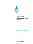
Once the Agilent B1500 receives a GPIB command, the Start EasyEXPERT button
is minimized to the Windows task bar, and the FlexGUI window shown in Figure
1-1 is opened. The FlexGUI window is the status indicator of the B1500 in the GPIB
remote state and provides the following GUI.
Figure 1-1
FlexGUI Window
RMT
LTN
TLK
SRQ
Measurement
GPIB Instrument Status
GPIB Commnad-Output Window
Model number and revision number
Tools menu
Help menu
Interface name
GPIB address
Go to Local & Close
Returns the B1500 to the local state and closes the
FlexGUI window. After that the Start EasyEXPERT button
appears.
Close
Substitution of Go to Local & Close when the B1500 is
already in the local state. Closes the FlexGUI window.
After that the Start EasyEXPERT button appears.
Options > Enable
GPIB Capturing
Enables or disables the GPIB log display function.
About FlexGUI
Opens the About FlexGUI dialog box.
1-4
Agilent B1500A/B1505A Programming Guide, Edition 11
Programming Basics
Before Starting
Model number and Shows the *IDN? command response.
revision number
Example: Agilent Technologies,B1500A,0,A.03.10.2007.1021
Interface name
Shows the name of the B1500 internal GPIB interface.
GPIB address
Shows the GPIB address set to the B1500.
GPIB Instrument
Status
Shows the B1500 remote status. Has the following indicators.
RMT
Turns green while the B1500 is in the GPIB remote state.
LTN
Turns green while the B1500 receives a GPIB command.
TLK
Turns green while the B1500 sends a response.
SRQ
Turns green since the service request occurs.
The last status display continues after the last communication.
Measurement
Measurement indicator. Turns green while measurement, self-test, self-calibration,
program memory, or compensation data measurement is executed.
Enable GPIB
Capturing
Enables or disables the GPIB log display function. This function can be set to ON
by checking this check box.
The GPIB log display function is useful for debugging a program. For the normal
remote operation, this function should be OFF.
GPIB CommandOutput Window
Displays the following information as the communication log when the GPIB log
display function is ON. No information is displayed when the function is OFF.
•
GPIB commands sent to the B1500
•
Response data sent from the B1500
•
Error messages sent from the B1500
The display items can be selected by using the combo box.
All
Displays all of the above information.
Errors
Displays the error messages only.
Commands Sent
Displays the GPIB commands only.
Response Data
Displays the response data only.
Commands Sent &
Response Data
Displays the GPIB commands and response data.
Agilent B1500A/B1505A Programming Guide, Edition 11
1-5
Programming Basics
Before Starting
The right-click menu is available in the GPIB log display area.
Copy
Copies the highlighted data to the clipboard.
Select All
Highlights all of the displayed information.
Save to File
Saves the displayed information as the specified file which
can be opened by using a text editor such as the Notepad.
Clear All
Deletes the displayed information.
Settings...
Available when the GPIB log display function is OFF.
Opens the Settings dialog box.
Settings dialog box
This dialog box is opened by selecting Settings... of the right-click menu on the
GPIB log display area, and is used to set the display update mode, the number of
elements to be displayed in a line, and the display format.
GPIB Capturing
Mode
Sets the display update mode to BYTE or BUFFER.
BYTE
Updates the log display every byte data which is one character
of ASCII format.
BUFFER
Updates the log display every buffer data which is data to a
terminator.
Elements(Respons Sets the number of elements displayed in a line to 4, 8, 16, 32, 64, or 128 elements.
e) in one Row
One element is equivalent to one character of the ASCII format data.
Display Format
Sets the following function ON or OFF. The function can be set to ON by checking
the check box.
Show Hex Data
Displays the values given in hexadecimal.
Show Ascii Data
Displays the values given in ASCII format.
Auto Clear
Clears the log display area automatically every display update.
However, if an error occurs, the error message will be left in the
log display area. Also, if the display update mode is BUFFER,
the last log will be left in this area.
OK
Applies the setup changes and closes the dialog box.
Cancel
Cancels the setup changes and closes the dialog box.
1-6
Agilent B1500A/B1505A Programming Guide, Edition 11
Programming Basics
Getting Started
Getting Started
This section explains the following basic operations. In this section, the HP BASIC
language is used for the examples.
•
“To Reset the Agilent B1500”
•
“To Read Query Response”
•
“To Perform Self-Test”
•
“To Perform Self-Calibration”
•
“To Perform Diagnostics”
•
“To Enable Source/Measurement Channels”
•
“To Select the Measurement Mode”
•
“To Force Voltage/Current”
•
“To Set the SMU Integration Time”
•
“To Set the Measurement Range”
•
“To Pause Command Execution”
•
“To Start Measurement”
•
“To Force 0 V”
•
“To Disable Source/Measurement Channels”
•
“To Control ASU”
•
“To Control SCUU”
•
“To Read Error Code/Message”
•
“To Read Spot Measurement Data”
•
“To Read Sweep Measurement Data”
•
“To Read Time Stamp Data”
•
“To Perform High Speed Spot Measurement”
Agilent B1500A/B1505A Programming Guide, Edition 11
1-7
Programming Basics
Getting Started
To Reset the Agilent B1500
The B1500 returns to the initial settings by the *RST command.
Example
OUTPUT @B1500;"*RST"
For the initial settings, see “Initial Settings” on page 2-87.
To Read Query Response
If you enter a query command such as the *TST?, ERR? and so on, the B1500 puts
an ASCII format response to the query buffer that can store only one response. Read
the response as soon as possible after entering a query command.
Example
OUTPUT @B1500;"NUB?"
ENTER @B1500;A
This example returns the number of data stored in the data output buffer.
To Perform Self-Test
The B1500 starts the self-test by the *TST? command. The *TST? command also
returns the test result.
Example
OUTPUT @B1500;"*TST?"
ENTER @B1500;Code
IF Code<>0 THEN DISP "FAIL: SELF-TEST"
This example starts the self-test, and reads the test result code. For the test result
code, see “*TST?” on page 4-206.
To Perform Self-Calibration
The B1500 starts the self-calibration by the *CAL? command.
Example
OUTPUT @B1500;"*CAL?"
ENTER @B1500;Result
IF Result<>0 THEN DISP "FAIL: CALIBRATION"
This example starts the self-calibration, and reads the result, pass or fail. For details,
see “*CAL?” on page 4-57.
1-8
Agilent B1500A/B1505A Programming Guide, Edition 11
Programming Basics
Getting Started
To Perform Diagnostics
The B1500 starts the diagnostics by the DIAG? command, and returns the result.
You must specify the diagnostics item by the command parameter. Available
parameter values are:
1: Trigger In/Out diagnostics
3: High voltage LED diagnostics
4: Digital I/O diagnostics
To perform diagnostics 1, connect a BNC cable between the Ext Trig In terminal
and the Ext Trig Out terminal before starting the diagnostics.
To perform diagnostics 4, disconnect any cable from the digital I/O port.
Example
OUTPUT @B1500;"DIAG? 1"
ENTER @B1500;Result
IF Result<>0 THEN DISP "FAIL: DIAGNOSTICS"
This example starts the Trigger In/Out diagnostics, and reads the result, pass or fail.
For details, see “DIAG?” on page 4-73.
To Enable Source/Measurement Channels
The measurement channels or source channels can be enabled by closing the output
switch. To close the switch, send the CN command. The B1500 closes the output
switch of the specified channels.
Example
OUTPUT @B1500;"CN 1"
This example enables channel 1 (the module installed in slot 1 of the B1500). If you
do not specify the channel, the CN command enables all channels.
To Select the Measurement Mode
The B1500 provides the measurement modes listed in Table 1-1. To select the
measurement mode, send the MM command. In the table, the Mode No. means a
command parameter of the MM command.
Syntax
MM Mode#[,Ch#[,Ch#] ... ]
where, Mode# specifies the Mode No., and Ch# specifies the measurement channel.
The available number of measurement channels depends on the measurement mode.
For details, see “MM” on page 4-136.
Agilent B1500A/B1505A Programming Guide, Edition 11
1-9
Programming Basics
Getting Started
Table 1-1
Measurement Mode
Measurement Mode (measurement parameter)
Example
Mode No.
Spot Measurement (current or voltage)
1
Staircase Sweep Measurement (current or voltage)
2
Pulsed Spot Measurement (current or voltage)
3
Pulsed Sweep Measurement (current or voltage)
4
Staircase Sweep with Pulsed Bias Measurement (current or voltage)
5
Quasi-Pulsed Spot Measurement (current or voltage)
9
Sampling Measurement (current or voltage)
10
Quasi-static CV Measurement (capacitance)
13
Linear Search Measurement (current or voltage)
14
Binary Search Measurement (current or voltage)
15
Multi Channel Sweep Measurement (current or voltage)
16
Spot C Measurement (impedance)
17
CV (DC bias) Sweep Measurement (impedance-DC voltage)
18
Pulsed Spot C Measurement (impedance)
19
Pulsed Sweep CV Measurement (impedance-voltage)
20
C-f Sweep Measurement (impedance-frequency)
22
CV (AC level) Sweep Measurement (impedance-AC voltage)
23
C-t Sampling Measurement (impedance)
26
Multi Channel Pulsed Spot Measurement (current or voltage)
27
Multi Channel Pulsed Sweep Measurement (current or voltage)
28
High Speed Spot Measurement (current, voltage, or impedance)
NA
OUTPUT @B1500;"MM 2,1"
This example sets the staircase sweep measurement, and assigns channel 1 (the
module installed in slot 1 of the B1500) as the measurement channel.
1-10
Agilent B1500A/B1505A Programming Guide, Edition 11
Programming Basics
Getting Started
NOTE
The Mode No. is not assigned for the high speed spot measurement. See “To
Perform High Speed Spot Measurement” on page 1-21. The high speed spot
measurement does not need the MM command.
For the source output commands available for each measurement mode, see Table
1-2.
Table 1-2
Measurement Mode and Available Source Output Commands
Measurement Mode
Command
Staircase Sweep Measurement
WV or WI, WSV or WSI
Pulsed Spot Measurement
PT, PV or PI
Pulsed Sweep Measurement
PT, PWV or PWI, WSV or WSI
Staircase Sweep with Pulsed Bias Measurement
PT, PV or PI, WV or WI, WSV or WSI
Quasi-Pulsed Spot Measurement
BDV
Sampling Measurement
MV, MI, MSP
Quasi-static CV Measurement
QSV
Linear Search Measurement
LSV or LSI, LSSV or LSSI
Binary Search Measurement
BSV or BSI, BSSV or BSSI
Multi Channel Sweep Measurement
WNX, WV or WI
CV (DC bias) Sweep Measurement
WDCV
Pulsed Spot C Measurement
PTDCV, PDCV
Pulsed Sweep CV Measurement
PTDCV, PWDCV
C-f Sweep Measurement
WFC
CV (AC level) Sweep Measurement
WACV
C-t Sampling Measurement
MDCV
Multi Channel Pulsed Spot Measurement
MCPT, MCPNT, MCPNX
Multi Channel Pulsed Sweep Measurement
MCPT, MCPNT, MCPWS, WNX,
MCPNX, MCPWNX
Agilent B1500A/B1505A Programming Guide, Edition 11
1-11
Programming Basics
Getting Started
To Force Voltage/Current
The commands listed in Table 1-3 is used to force voltage or current. These
commands start to force the voltage or current immediately when the command is
executed. They can be used regardless of the measurement mode.
See Table 1-2 on page 1-11 for the commands available for each measurement
mode. The commands just set the source channel condition, and the source channel
starts the output by the start trigger, such as the XE command. For more details of
the commands, see Chapter 4, “Command Reference.”
Table 1-3
Voltage/Current Output Commands
Command
DV
Applies DC voltage from SMU immediately.
DI
Applies DC current from SMU immediately.
FC/ACV
Applies AC voltage from CMU immediately.
DCV
Applies DC bias from CMU immediately.
TDV
Applies DC voltage from SMU, and returns the time data.
TDI
Applies DC current from SMU, and returns the time data.
FC/TACV
Applies AC voltage from CMU, and returns the time data.
TDCV
Example
Description
Applies DC bias from CMU, and returns the time data.
OUTPUT @B1500;"DV 1,0,5"
This example just forces 5 V using channel 1 (the module installed in slot 1 of the
B1500) with auto ranging.
1-12
Agilent B1500A/B1505A Programming Guide, Edition 11
Programming Basics
Getting Started
To Set the SMU Integration Time
To adjust the balance of the SMU’s measurement accuracy and speed, change the
integration time or the number of averaging samples of the A/D converter (ADC) by
using the AV command. The AV command is compatible with the AV command of
the Agilent 4142B.
For accurate and reliable measurement, set the integration time longer or set the
number of samples larger. For details about the integration time settings, see
Chapter 4, “Command Reference.”
The following type of the ADC is available. Use the AAD command to select the
type, and use the AIT command to set the integration time or the number of samples.
Type
Description
High-speed ADC
Effective for the high speed measurement. In the multi
channel sweep measurement mode (MM16), multiple
measurement channels can perform synchronous
measurements. The number of averaging samples must be
set by the AV or AIT command.
High-resolution
ADC
Effective for the accurate measurement. Cannot be used
for the pulsed measurement channel and the simultaneous
measurement channel. The integration time must be set by
the AIT command.
Not available for the HCSMU and HVSMU.
Pulsed
measurement ADC
Example
Always used for the pulsed measurement. The number of
averaging samples must be set by the AIT.
The following example sets the number of samples to 10 for the high-speed A/D
converter.
OUTPUT @B1500;"AV 10,1"
The following example sets the power line cycle mode (PLC) for both the
high-speed ADC and the high-resolution ADC. And channel 1 uses the
high-resolution ADC and other channels use the high-speed ADC.
OUTPUT
OUTPUT
OUTPUT
OUTPUT
@B1500;"*RST"
@B1500;"AIT 0,2"
@B1500;"AIT 1,2"
@B1500;"AAD 1,1"
Agilent B1500A/B1505A Programming Guide, Edition 11
1-13
Programming Basics
Getting Started
To Set the Measurement Range
To set the measurement range, send the following command:
Command
RI
RV
RC
TI, TTI
TV, TTV
TIV, TTIV
TC, TTC
Description
Sets the current measurement range. Available for the
current measurements that use the XE command. Not
available for the high speed spot measurement.
Sets the voltage measurement range. Available for the
voltage measurements that use the XE command. Not
available for the high speed spot measurement.
Sets the impedance measurement range. Available for the
CV sweep/spot C measurements.
Sets the current measurement channel and range, and
performs the high speed spot measurement.
Sets the voltage measurement channel and range, and
performs the high speed spot measurement.
Sets the current and voltage measurement channel and
ranges, and performs the high speed spot measurement.
Sets the impedance measurement channel and range, and
performs the high speed spot measurement.
For the current measurement with the auto ranging mode, you can specify the
coverage of each measurement range. To specify the coverage, send the RM
command.
For details, see Chapter 4, “Command Reference.”
Example
This example sets the voltage measurement ranging mode of channel 1 to auto.
OUTPUT @B1500;"RV 1,0"
This example sets the current measurement ranging mode of channel 1 to auto, and
specifies coverage between 9 % and 90 % of the range value or between 90 mA and
180 mA for the 200 mA range.
OUTPUT @B1500;"RI 1,0"
OUTPUT @B1500;"RM 1,3,90"
NOTE
To use 1 pA range of ASU
Set the 1 pA limited auto ranging mode or the 1 pA fixed range mode. Or enable the
1 pA range for the auto ranging mode by using the SAR command. See “SAR” on
page 4-172.
1-14
Agilent B1500A/B1505A Programming Guide, Edition 11
Programming Basics
Getting Started
To Pause Command Execution
To pause command execution until the specified wait time elapses, send the PA
command.
Example
OUTPUT @B1500;"PA 5"
If this command is sent, the B1500 waits 5 seconds before executing the next
command.
To Start Measurement
To start measurement other than the high speed spot measurement, send the XE
command.
Example
OUTPUT @B1500;"XE"
This starts the measurement specified by the MM command.
For the high speed spot measurement, see “To Perform High Speed Spot
Measurement” on page 1-21.
To Force 0 V
To force 0 V immediately, send the DZ command. The B1500 memorizes the
present source output settings of the specified channel, and changes the specified
channel output to 0 V. If you do not specify the channel, the DZ command function
is effective for all channels.
Example
OUTPUT @B1500;"DZ 1"
If this command is sent, the B1500 memorizes the current settings of channel 1 (the
module installed in slot 1 of the B1500), and changes channel 1 output to 0 V.
To restore the settings stored by the DZ command, send the RZ command. For
details, see Chapter 4, “Command Reference.”
Agilent B1500A/B1505A Programming Guide, Edition 11
1-15
Programming Basics
Getting Started
To Disable Source/Measurement Channels
To disable the channels, send the CL command. The B1500 opens the output switch
of the specified channels. Opening the output switch disables the channel.
Example
OUTPUT @B1500;"CL 1"
This example disables channel 1 (the module installed in slot 1 of the B1500). If you
do not specify the channel, the CL command disables all channels.
To Control ASU
This function is available for Agilent B1500A. ASU (atto sense and switch unit) has
two inputs, SMU input for the B1511B/B1517A and AUX input for the other
instrument. And the ASU input to output connection can be controlled by the
following commands. When the B1500 is turned on, the SMU input will be
connected to the ASU output. However, the SMU output switch will be off at this
time.
Table 1-4
ASU Input Output Connection Control
Previous Connection
Command
Subsequent Connection
SMU side, Output on/off
SAP chnum, 1
AUX side
SMU side, Output off
CN chnum
SMU side, Output on
SAP chnum, 0
AUX side
CN chnum
SAP chnum, 0
CL [chnum]
SMU side, Output on
SMU side, Output off
CL [chnum]
where, chnum must be the channel number of the SMU connected to the ASU. See
“SAL”, “SAP”, and “SAR” on page 4-172 for the other function and control
commands of the ASU.
When the SMU side is connected to the ASU output, the source output on/off can be
controlled by the CN/CL command. And then the SAP chnum, 1 command is used
to change the output connection to the AUX side. When the AUX side is connected,
the output of the instrument connected to the AUX input is appeared to the ASU
output immediately.
1-16
Agilent B1500A/B1505A Programming Guide, Edition 11
Programming Basics
Getting Started
To Control SCUU
This function is available for Agilent B1500A. SCUU (SMU CMU unify unit) can
be used with one capacitance measurement unit (CMU) and two SMUs (MPSMU or
HRSMU). The SCUU cannot be used with the HPSMU or when only one SMU is
connected. The SCUU input to output connection can be controlled by the following
commands. When the B1500 is turned on, the SCUU input to output connection is
not made (open).
Table 1-5
SCUU Input Output Connection Control
SCUU output connection after the command
Command
CMUH/Force1/Sense1
CMUL/Force2/Sense2
SSP chnum, 1
Force1/Sense1
Open
SSP chnum, 2
Open
Force2/Sense2
SSP chnum, 3
Force1/Sense1
Force2/Sense2
SSP chnum, 4
CMUH
CMUL
Force1/Sense1 is connected to the SMU installed in the slot numbered slot-1.
Force2/Sense2 is connected to the SMU installed in the slot numbered slot-2.
where, slot is the slot number given by chnum. When the SCUU input to output
connection is made, the measurement unit output switch will be automatically set to
ON.
When the connection is changed from SMU to CMU, the SMU output will be set as
follows. The other setup parameters are not changed.
Output voltage
0V
Output range
100 V
Compliance
20 mA
Series resistance
OFF
When the connection is changed from CMU to SMU, the SMU output will be set as
follows. The other setup parameters are not changed.
Output voltage
0V
Output range
20 V
Compliance
100 μA
Series resistance
Condition before the connection is changed from SMU to CMU
Agilent B1500A/B1505A Programming Guide, Edition 11
1-17
Programming Basics
Getting Started
To Read Error Code/Message
If any error occurs, the B1500 will not put the measurement data into the data output
buffer. Hence, confirm that no error has occurred before reading the measurement
data. To read the error code and the error message, enter the ERRX? command.
Example
OUTPUT @B1500;"ERRX?"
ENTER @B1500;Code,Msg$
IF Code<>0 THEN
PRINT "ERROR: ";Msg$
ELSE
:
:
This example checks the error buffer, and prints the error message on the computer
screen if any error code is stored in the error buffer.
ERR? and EMG? commands are also available. These commands support the error
codes 0 to 999.
To Read Spot Measurement Data
After the spot measurements, the B1500 puts the measurement data into its output
data buffer. You can read the data as shown below. The examples read the header
information and the measurement data included in the ASCII data set by the FMT5
command. For the data output format, see “Data Output Format” on page 1-25. The
example uses the HP BASIC or Microsoft Visual Basic .NET language.
Example 1
For the HP BASIC users, use the ENTER statement.
ENTER @B1500 USING "#,3A,12D,X";Head$,Mdata
Example 2
For the VISA library users, use the viScanf, viRead, or another function.
Dim ret_rd As System.Text.StringBuilder = _
New System.Text.StringBuilder(3 + 12 + 1)
ret = viScanf(vi, "%t", ret_rd)
ret_val = ret_rd.ToString()
head = Left(ret_val, 3)
mdata = Val(Mid(ret_val, 4, 12))
Example 3
For the VISA COM library users, use the ReadString or another method.
ret_val = B1500.ReadString(3 + 12 + 1)
head = Left(ret_val, 3)
mdata = Val(Mid(ret_val, 4, 12))
1-18
Agilent B1500A/B1505A Programming Guide, Edition 11
Programming Basics
Getting Started
To Read Sweep Measurement Data
For the sweep measurements, the measurement data will be put into the data output
buffer after every step measurement. You can read the data as shown below. The
examples use the VISA COM library and Microsoft Visual Basic .NET language.
For the data output format, see “Data Output Format” on page 1-25.
•
To read data after sweep measurement
This way waits for the measurement completion by using the *OPC? command
after the XE command, and reads the sweep data (all step measurement data) at
once after the sweep measurement is completed. For the specific example, see
Table 3-5 on page 3-19.
Example:
B1500.WriteString("FMT 5,0" & vbLf)
’terminator=comma
B1500.WriteString("XE" & vbLf)
B1500.WriteString("*OPC?" & vbLf)
rep = B1500.ReadString(1 + 2)
’Response+CRLF
ret_val = B1500.ReadString(16 * nop)
For i = 0 To nop - 1
’nop=number of sweep steps
head = Mid(ret_val, 16 * i + 1, 3)
mdata = Val(Mid(ret_val, 16 * i + 4, 12))
ddata = "Data = " & mdata & ", Header = " & head
Console.WriteLine(ddata)
Next i
•
To read data after every step measurement
This way starts to read the data after the XE command. You do not need to wait
for the sweep measurement completion. So you can check the result data before
the sweep measurement is completed. For the specific example, see Table 3-6 on
page 3-22.
Example:
B1500.WriteString("FMT 5,0" & vbLf)
’terminator=comma
B1500.TerminationCharacter = Chr(44)
’Chr(44)=comma
B1500.TerminationCharacterEnabled = True ’enables comma
B1500.WriteString("XE" & vbLf)
For i = 0 To nop - 1
’nop=number of sweep steps
ret_val = B1500.ReadString(3 + 12 + 1)
head = Left(ret_val, 3)
mdata = Val(Mid(ret_val, 4, 12))
ddata = "Data = " & mdata & ", Header = " & head
Console.WriteLine(ddata)
Next i
Agilent B1500A/B1505A Programming Guide, Edition 11
1-19
Programming Basics
Getting Started
To Read Time Stamp Data
NOTE
This function is not available for the quasi-pulsed spot measurement (MM 9), search
measurement (MM 14 or 15), and the 4 byte binary data output (FMT 3 or 4).
To read the time data with the best resolution (100 μs), clear the timer every 100 s or
less (for FMT 1, 2, or 5), or 1000 s or less (for FMT 11, 12, 15, 21, 22, or 25).
The time stamp function records the time from timer reset (Time=0 s) to the start of
measurement. This function is enabled by the TSC command. The timer count is
cleared/reset by the TSR command.
For example, the output data in the staircase sweep measurement will be as follows:
Block1 [,Block2] . . . . <terminator>
BlockN (N: integer) = Time1,Data1 [,Time2,Data2] ... [,Source_data]
TimeN (N: integer) is the time from timer reset to the start of DataN measurement.
Without the TSC command, you can get the time data by the following commands:
•
TDV / TDI (for voltage/current output by using a SMU),
TDCV / TACV (for DC voltage/AC voltage output by using the CMU):
Starts source output, and returns the time data from timer reset (TSR command)
to the start of output.
Example:
•
OUTPUT @B1500;"TDV 1,0,20"
ENTER @B1500 USING "#,5X,13D,X";Time
PRINT "Time=";Time;"sec"
TTV / TTI / TTIV (for voltage/current measurement by using a SMU),
TTC (for impedance measurement by using the CMU):
Executes high speed spot measurement, and returns the measurement data and
the time data from timer reset (TSR command) to the start of measurement.
Example:
•
OUTPUT @B1500;"TTV 1,0"
ENTER @B1500 USING "#,5X,13D,X";Time
ENTER @B1500 USING "#,5X,13D,X";Mdata
PRINT "Data=";Mdata;" at ";Time;"sec"
TSQ: Returns the time data from timer reset (TSR command) to this command.
Example:
1-20
OUTPUT @B1500;"TSR"
!Resets count
:
OUTPUT @B1500;"TSQ"
!Returns time data
ENTER @B1500 USING "#,5X,13D,X";Time
PRINT "Time=";Time;"sec"
Agilent B1500A/B1505A Programming Guide, Edition 11
Programming Basics
Getting Started
To Perform High Speed Spot Measurement
The high speed spot measurement does not need the MM and XE commands to set
the measurement mode and start measurement. To start and perform the high speed
spot measurement immediately, send the TI/TTI/TV/TTV/TIV/TTIV command to a
SMU for the DC current or voltage measurement, or the TC/TTC command to the
CMU for the impedance measurement. The following example program measures
current by using the TI command, and displays the measurement result data on the
computer screen.
Example
10
20
30
40
50
60
70
80
90
100
110
120
130
140
ASSIGN @B1500 TO 717
OUTPUT @B1500;"*RST"
OUTPUT @B1500;"FMT 5"
OUTPUT @B1500;"CN 1,2,3,4"
OUTPUT @B1500;"DV 1,0,0"
OUTPUT @B1500;"DV 2,0,0"
OUTPUT @B1500;"DV 3,0,2"
OUTPUT @B1500;"DV 4,0,5"
OUTPUT @B1500;"TI 4,0"
ENTER @B1500 USING "#,3A,12D,X";Head$,Data
PRINT Head$,Data
OUTPUT @B1500;"DZ"
OUTPUT @B1500;"CL"
END
Line
Number
Description
10
Assigns the I/O path to control the B1500.
20
Initializes the B1500.
30
Sets the data output format (ASCII with header and <,>).
40
Enables channels 1, 2, 3, and 4.
50 to 80
Forces the DC voltage. Channel 1 and 2 force 0 V, channel 3 forces
2 V, and channel 4 forces 5 V with auto ranging.
90
Performs the high speed spot measurement using channel 4 with
auto ranging.
100 to 110
Prints the header data and measurement data on the screen.
120
Forces 0 V. All channels force 0 V.
130
Disables all channels.
Agilent B1500A/B1505A Programming Guide, Edition 11
1-21
Programming Basics
Command Input Format
Command Input Format
Agilent FLEX commands (GPIB commands for the Agilent B1500) are composed
of a header, numeric data, and terminator, as shown in the following syntax diagram.
B1500 Control Command Syntax Diagram
;
,
Header
Separator
Numeric Data
SP
SP
Terminator
SP
SP : Space
NOTE
Terminator
Terminator is necessary to enter the command to the Agilent B1500. For the
available terminators, see “Terminator” and “Special Terminator” on page 1-24.
Header
The header is the command name, always contains alpha characters, and is not
upper or lowercase sensitive. Some command names also contain an asterisk (*) or
question mark (?). The following figure shows the syntax diagram for a header.
Header Syntax Diagram
Alpha Character
(A to Z, a to z)
*
1-22
?
Agilent B1500A/B1505A Programming Guide, Edition 11
Programming Basics
Command Input Format
Numeric Data
Numeric data are the command parameters. You can enter numeric data directly
after the header or insert spaces between the header and numeric data. Some
parameters require integer data. The following figure shows the syntax diagram for
numeric data.
Numeric Data Syntax Diagram
Integer Data
Fixed Point Data
Floating Point Data
The following 3 figures show the syntax diagrams for integer, fixed point, and
floating point data, respectively.
Integer Data Syntax Diagram
+
Digit
(0 to 9)
−
SP
SP
SP : Space
Fixed Point Data Syntax Diagram
+
SP
−
Digit
(0 to 9)
Digit
(0 to 9)
SP
SP : Space
Floating Point Data Syntax Diagram
+
SP
−
Digit
(0 to 9)
+
Digit
(0 to 9)
E
e
−
*1
Digit
(0 to 9)
SP
SP : Space
*1: Here must be 2 digits or less.
Agilent B1500A/B1505A Programming Guide, Edition 11
1-23
Programming Basics
Command Input Format
Terminator
The terminator completes the GPIB command entry and starts command execution.
The following figure shows the terminator syntax diagram.
Terminator Syntax Diagram
^
EOI
CR
LF
LF
^
EOI
Special Terminator
If a semicolon (;) is inserted before the terminator, as shown in the following figure,
the preceding commands are not executed until the next command line is input and
another terminator is input, without a preceding semicolon. The command lines are
then executed together.
Special Terminator Syntax Diagram
;
CR
LF
LF
^
EOI
Separator
If you enter multiple commands, use semicolons (;) to separate the commands.
Spaces are allowed before and after the semicolons. Command execution starts
when the terminator is received, not when the semicolon is received. You can input
multiple commands of up to a total of 256 characters (including the terminator). If
you input more than 256 characters, the input buffer overflows, and an error is
indicated.
Use commas (,) to separate numeric data entries.
NOTE
Do not include the reset command (*RST) or the abort command (AB) in multiple
command strings (example: OUTPUT @B1500;”*RST;CN”). If you do, the other
commands in the string (example: CN) are not executed.
1-24
Agilent B1500A/B1505A Programming Guide, Edition 11
Programming Basics
Data Output Format
Data Output Format
Agilent B1500 provides the following data output formats:
•
“ASCII Data Output Format”
The B1500 supports the ASCII data format that is the common format for the
instruments that support the Agilent FLEX command mode.
•
“Binary Data Output Format”
The B1500 supports the 4 bytes binary data format that is the common format
for the instruments that support the Agilent FLEX command mode. The B1500
also supports the dedicated 8 bytes binary format. The binary format enables
faster data transfer time than ASCII format. You need to calculate the data to get
the measurement result.
To select the data output format, use the FMT command. See “FMT” on page 4-105.
For the query response, the returned data is always stored in the query buffer in
ASCII format, regardless of the FMT command setting.
Conventions
The following conventions are used in this section.
Data
Output data that the B1500 sends after a measurement.
[Data]
Optional output data sent when there are multiple output data
items.
For example, source data will be sent with measurement data
after the staircase sweep measurements when the source data
output is enabled by the FMT command.
<terminator>
Terminator.
<CR/LF^EOI> (two bytes) or <,> (one byte) for ASCII data.
<CR/LF^EOI> (two bytes) or <^EOI> (0 byte) for binary data.
You can select by using the FMT command.
Agilent B1500A/B1505A Programming Guide, Edition 11
1-25
Programming Basics
Data Output Format
ASCII Data Output Format
This section describes the ASCII data output format, and the elements of the data.
•
“Time Stamp”
•
“Data Format”
•
“Data Elements”
Time Stamp
The B1500 can record the time when the measurement is started, and sends the time
data (Time). This function is enabled by the TSC command. The time data will be
sent just before the measurement data.
For example, in the staircase sweep measurements, the data will be as shown below.
Block1 [,Block2] . . . . <terminator>
where, BlockN (N: integer) = Time1,Data1 [,Time2,Data2] ... [,Source_data], then
TimeN (N: integer) is the time from timer reset to the start of DataN measurement.
The timer count is cleared/reset by the TSR command (Time=0).
The time stamp function is not available for the following measurements.
•
High speed spot measurement
•
Quasi-pulsed spot measurement (MM9)
•
Linear search measurement (MM14)
•
Binary search measurement (MM15)
1-26
Agilent B1500A/B1505A Programming Guide, Edition 11
Programming Basics
Data Output Format
Data Format
The data output format depends on the measurement mode as shown below.
High speed spot
Data <terminator>
(by TI, TV, TMACV, or TMDCV command)
Time,Data <terminator>
(by TTI or TTV command)
Para1,Para2 <terminator>
(by TIV or TC command)
Time,Para1,Para2 <terminator>
(by TTIV or TTC command)
Data is the value measured by the channel you specify in the command. Time is the
time from timer reset to the start of measurement. Para1 and Para2 are current (A)
and voltage (V) respectively measured by the SMU or the primary and secondary
parameters (ex: Cp and G) respectively measured by the CMU. The CMU
measurement data is selected by the IMP command. See Table 4-16 on page 4-29.
TDI, TDV, TSQ,
TACV, TDCV
command
Time <terminator>
Spot,
Multi channel
pulsed spot
Data1 [,Data2] . . . . <terminator>
Time is the time from timer reset to the start of output.
DataN (N: integer) is the value measured by a channel. The order of Data is defined
by the MM command.
Data <terminator>
Pulsed spot,
Quasi-pulsed spot,
Data is the value measured by the channel you specify by using the MM command.
Spot C,
Pulsed spot C
For the spot C measurement, Data will be Para1,Para2 [,Osc_level,Dc_bias].
For the pulsed spot C measurement, Data will be Para1,Para2.
Para1 and Para2 are the primary and secondary parameters (ex: Cp and G). They
are selected by the IMP command. See Table 4-16 on page 4-29. And Osc_level and
Dc_bias are the monitor values of the oscillator level (AC signal level) and the DC
bias respectively. They are sent if the data output is enabled by the LMN command.
Linear search,
Binary search
Data_search [,Data_sense]<terminator>
This is the data at the measurement point closest to the search target. Data_search is
the value forced by the search output channel. Data_sense is the value measured by
the search monitor channel. It is sent if data output is enabled by the BSVM
command for the binary search, or the LSVM command for the linear search.
Agilent B1500A/B1505A Programming Guide, Edition 11
1-27
Programming Basics
Data Output Format
Staircase sweep,
Multi channel
sweep,
Multi channel
pulsed sweep,
CV (DC bias)
sweep
Block1 [,Block2] . . . . <terminator>
Block1 is the block of data measured at the first sweep point.
Block2 is the block of data measured at the second sweep point.
where Block consists of the following data:
Data1 [,Data2] . . . . [,Source_data]
DataN (N: integer) is the value measured by a channel. The order of Data is defined
by the MM command. Source_data is the sweep source output value. It is sent if the
data output is enabled by the FMT command.
For the CMU measurement data, DataN will be Para1,Para2 [,Osc_level,Dc_bias].
Para1 and Para2 are the primary and secondary parameters (ex: Cp and G). They
are selected by the IMP command. See Table 4-16 on page 4-29. And Osc_level and
Dc_bias are the monitor values of the oscillator level (AC signal level) and the DC
bias respectively. They are sent if the data output is enabled by the LMN command.
Pulsed sweep,
Staircase sweep
with pulsed bias,
Pulsed sweep CV,
CV (AC level)
sweep,
C-f sweep
Block1 [,Block2] . . . . <terminator>
Block1 is the block of data measured at the first sweep point.
Block2 is the block of data measured at the second sweep point.
where Block consists of the following data:
Data [,Source_data]
Data is the value measured by the channel you specify by using the MM command.
Source_data is the sweep source output value. It is sent if the data output is enabled
by the FMT command.
For the pulsed sweep CV measurement, Data will be Para1,Para2.
For the CV (AC level) and C-f, Data will be Para1,Para2 [,Osc_level,Dc_bias].
Para1 and Para2 are the primary and secondary parameters (ex: Cp and G). They
are selected by the IMP command. See Table 4-16 on page 4-29. And Osc_level and
Dc_bias are the monitor values of the oscillator level (AC signal level) and the DC
bias respectively. They are sent if the data output is enabled by the LMN command.
1-28
Agilent B1500A/B1505A Programming Guide, Edition 11
Programming Basics
Data Output Format
Sampling,
C-t sampling
Block1 [,Block2] . . . . <terminator>
Block1 is the block of the data measured at the first sampling point.
Block2 is the block of the data measured at the second sampling point.
where Block consists of the following data:
[Sampling_no,] Data1 [,Data2] . . . .
Sampling_no is the sampling point index, and is returned by entering the FMT
command with mode<>0. This value depends on the sampling interval setting and
the measurement time. If the measurement time is shorter than the sampling
interval, Sampling_no will be N of BlockN (N: 1, 2, 3 . . . ).
DataN (N: integer) is the data measured by one unit. The order of Data is specified
by the MM command. Sampling_no and Data values can be discarded when the
range changing is occurred while the measurement with auto or limited auto
ranging.
If the measurement time is longer than the sampling interval, Sampling_no is not N
of BlockN. For example, if the measurement time is longer than the sampling
interval and shorter than twice the sampling interval, then the Sampling_no is 2 for
Block1, and 4 for Block2. In general, the measurement time depends on the
measurement value and the A/D converter settings.
For the C-t sampling, DataN will be Para1,Para2.
Para1 and Para2 are the primary parameter and the secondary parameter (ex: Cp
and G). They are selected by the IMP command. See Table 4-16 on page 4-29.
Quasi-static CV
Block1 [,Block2] . . . . <terminator>
Block1 is the block of the data measured at the first sweep point.
Block2 is the block of the data measured at the second sweep point.
where Block consists of the following data:
[DataL,] DataC [,Source_data]
DataL is the leakage current measurement data. DataC is the capacitance
measurement data. Source_data is the sweep source output value. DataL and
Source_data are sent if the data output is enabled by the QSL or FMT command.
Agilent B1500A/B1505A Programming Guide, Edition 11
1-29
Programming Basics
Data Output Format
Data Elements
The data (Data, Source_data, Time, Sampling_no, Data_search, Data_sense,
Osc_level, and Dc_bias) are the string as shown in Table 1-6.
The data elements depends on the FMT command setting. Details of the elements
are described on the following pages.
Table 1-6
A:
Status. One character.
B:
Channel number. One character.
C:
Data type. One character.
D:
Data. Twelve digits or 13 digits.
E:
Status. Three digits.
F:
Channel number. One character.
G:
Data type. One character.
Data Elements
Data
ABCDDDDDDDDDDDD
FMT command
FMT1 or FMT5
ABCDDDDDDDDDDDDD
FMT11 or FMT15
EEEFGDDDDDDDDDDDDD
FMT21 or FMT25
DDDDDDDDDDDD
DDDDDDDDDDDDD
1-30
FMT2
FMT12 or FMT22
Agilent B1500A/B1505A Programming Guide, Edition 11
Programming Basics
Data Output Format
A
Status. One character.
•
Status for Source_data: See Table 1-7 on page 1-32.
Severity of a status is W<E.
•
Status for measurement data: See Table 1-10 on page 1-33.
For SMU, the severity of a status is as follows:
•
For the quasi-pulsed spot measurement: N<T<C<V<X<G or S
•
For other measurement: N<G<S<T<C<V<X
B
Channel number of the measurement/source channel. One character. See Table 1-11
on page 1-34.
C
Data type. One character. See Table 1-12 on page 1-35.
D
Measurement data, output data, time data, or sampling index. Twelve or 13 digits
depends on FMT setting, which may be one of the following:
•
sn.nnnnnEsnn or sn.nnnnnnEsnn
•
snn.nnnnEsnn or snn.nnnnnEsnn
•
snnn.nnnEsnn or snnn.nnnnEsnn
where,
s: Sign, + or -.
n: Digit, 0 to 9.
E: Exponent symbol.
E
Status. Three digits. Ignore status for the Time value.
•
Status for Source_data: See Table 1-7 on page 1-32.
Severity of a status is W<E.
•
Status for measurement data:
For SMU status, see Table 1-8 on page 1-32.
For CMU status, see Table 1-9 on page 1-32.
If multiple status conditions are found, the sum of the EEE values is returned.
For example, if an A/D converter overflow occurred, and an SMU was
oscillating during the measurements, the returned EEE value is 3 (=1+2).
Agilent B1500A/B1505A Programming Guide, Edition 11
1-31
Programming Basics
Data Output Format
F
Channel number of the source/measurement module. One character. See Table 1-11
on page 1-34.
G
Data type. One character. Also see Table 1-12 on page 1-35.
Table 1-7
Source Data Status
A or EEE
Table 1-8
Explanation
W
Data is for the first or intermediate sweep step.
E
Data is for the last sweep step.
SMU Status
EEE
Table 1-9
Explanation
1
A/D converter overflowed.
2
Oscillation or force saturation occurred.
4
Another unit reached its compliance setting.
8
This unit reached its compliance setting.
16
Target value was not found within the search range.
32
Search measurement was automatically stopped.
64
Invalid data is returned. D is not used.
128
EOD (End of Data).
CMU Status
EEE
Explanation
1
A/D converter overflowed.
2
CMU is in the NULL loop unbalance condition.
4
CMU is in the IV amplifier saturation condition.
8
Not assigned.
16
Not assigned.
32
Not assigned.
64
Invalid data is returned. D is not used.
128
EOD (End of Data).
1-32
Agilent B1500A/B1505A Programming Guide, Edition 11
Programming Basics
Data Output Format
Table 1-10
Status for Measurement Data
A
Explanation
N
No status error occurred.
T
Another channel reached its compliance setting.
C
This channel reached its compliance setting.
V
Measurement data is over the measurement range. Or the sweep measurement
was aborted by the automatic stop function or power compliance. D will be
199.999E+99 (no meaning).
X
One or more channels are oscillating. Or source output did not settle before
measurement.a
F
SMU is in the force saturation condition.
G
For linear or binary search measurement, the target value was not found within
the search range. Returns the source output value.
For quasi-pulsed spot measurement, the detection time was over the limit (3 s for
Short mode, 12 s for Long mode).b
S
For linear or binary search measurement, the search measurement was stopped.
Returns the source output value. See status of Data_sense.
For quasi-pulsed spot measurement, output slew rate was too slow to perform the
settling detection.c Or quasi-pulsed source channel reached the current
compliance before the source output voltage changed 10 V from the start
voltage.d
U
CMU is in the NULL loop unbalance condition.
D
CMU is in the IV amplifier saturation condition.
a. Make the wait time or delay time longer. Or make the current compliance larger. For
pulsed measurement, make the pulse width longer, or make the pulse base value
closer to the pulse peak value. For current output by limited auto ranging, make the
output range lower.
b. Make the current compliance or start voltage larger. Or set the detection interval to
Long. If this status occurs with the Long mode, perform the spot measurement.
c. Make the current compliance larger. Or set the detection interval to Long. If this status occurs with the Long mode, perform the spot measurement or pulsed spot measurement.
d. Perform the pulsed spot measurement or spot measurement.
Agilent B1500A/B1505A Programming Guide, Edition 11
1-33
Programming Basics
Data Output Format
Table 1-11
Channel Number
Explanationa
B or F
A
Subchannel 1 of the module installed in the slot 1
B
Subchannel 1 of the module installed in the slot 2
C
Subchannel 1 of the module installed in the slot 3
D
Subchannel 1 of the module installed in the slot 4
E
Subchannel 1 of the module installed in the slot 5
F
Subchannel 1 of the module installed in the slot 6
G
Subchannel 1 of the module installed in the slot 7
H
Subchannel 1 of the module installed in the slot 8
I
Subchannel 1 of the module installed in the slot 9
J
Subchannel 1 of the module installed in the slot 10
a
Subchannel 2 of the module installed in the slot 1
b
Subchannel 2 of the module installed in the slot 2
c
Subchannel 2 of the module installed in the slot 3
d
Subchannel 2 of the module installed in the slot 4
e
Subchannel 2 of the module installed in the slot 5
f
Subchannel 2 of the module installed in the slot 6
g
Subchannel 2 of the module installed in the slot 7
h
Subchannel 2 of the module installed in the slot 8
i
Subchannel 2 of the module installed in the slot 9
j
Subchannel 2 of the module installed in the slot 10
F
Explanation
V
Ground unit (GNDU)
Z
Status code for extraneous data in the channel. TSQ
command response or invalid data is returned.
a. SMU and CMU do not have the subchannel 2.
1-34
Agilent B1500A/B1505A Programming Guide, Edition 11
Programming Basics
Data Output Format
Table 1-12
Data Type
C
Explanation
V
Voltage (V)
I
Current (A)
F
Frequency (Hz)
C or G
Explanation
Z
Impedance, resistance, or reactance (Ω)
Y
Admittance, conductance, or susceptance (S)
C
Capacitance (F)
L
Inductance (H)
R
Phase (radian)
P
Phase (degree)
D
Dissipation factor
Q
Quality factor
X
Sampling index
T
Time (second)
G
Explanation
V
Voltage measurement value (V)
I
Current measurement value (A)
v
Voltage output value (V)
i
Current output value (A)
f
Frequency (Hz)
z
invalid data
Agilent B1500A/B1505A Programming Guide, Edition 11
1-35
Programming Basics
Data Output Format
Binary Data Output Format
This section describes the binary data output format, and the elements of the data.
•
“Time Stamp”
•
“Data Resolution”
•
“Data Format”
•
“4 Bytes Data Elements”
•
“8 Bytes Data Elements”
Time Stamp
The B1500 can record the time when the measurement is started, and sends the time
data (Time). This function is enabled by the TSC command. The time data will be
sent just before the measurement data.
For example, in the staircase sweep measurements, the data will be as shown below.
Block1 [Block2] . . . . <terminator>
where, BlockN (N: integer) = Time1 Data1 [Time2 Data2] ... [Source_data], then
TimeN (N: integer) is the time from timer reset to the start of DataN measurement.
The timer count is cleared/reset by the TSR command (Time=0).
The time stamp function is not available for the following measurements.
•
4 bytes binary data format (FMT3 or FMT4)
•
High speed spot measurement
•
Quasi-pulsed spot measurement (MM9)
•
Linear search measurement (MM14)
•
Binary search measurement (MM15)
1-36
Agilent B1500A/B1505A Programming Guide, Edition 11
Programming Basics
Data Output Format
Data Resolution
The 4 bytes binary data format provides the following data resolution. To use this
data format, enter the FMT3 or FMT4 command. The resolution of the SMU
measurement value will be larger than the measurement resolution of the B1500’s
high resolution A/D converter. For Range value, see “4 Bytes Data Elements” on
page 1-41.
•
SMU measurement value (voltage or current): Range / 50000
•
SMU output value (voltage or current): Range / 20000
•
CMU measurement value (resistance or reactance): Range / 212
•
CMU measurement value (conductance or susceptance): 1 / (Range × 212)
•
CMU oscillator level monitor value (Vac), DC bias monitor value (Vdc),
frequency (Hz): Range / 50000
•
CMU DC bias output value: 2 mV
The 8 bytes binary data format provides the following data resolution. To use this
data format, enter the FMT13 or FMT14 command. For Range value, see “8 Bytes
Data Elements” on page 1-48.
•
SMU measurement/output value (voltage or current): Range / 1000000
•
CMU measurement value (resistance or reactance): Range / 224
•
CMU measurement value (conductance or susceptance): 1 / (Range × 224)
•
CMU oscillator level monitor value (Vac), DC bias monitor value (Vdc),
frequency (Hz): Range / 1000000
•
CMU DC bias output value: 1 mV
Agilent B1500A/B1505A Programming Guide, Edition 11
1-37
Programming Basics
Data Output Format
Data Format
The data output format depends on the measurement mode as shown below.
High speed spot
Data <terminator>
(by TI, TV, TMACV, or TMDCV command)
Time Data <terminator>
(by TTI or TTV command)
Para1 Para2 <terminator>
(by TIV / TC command)
Time Para1 Para2 <terminator>
(by TTIV / TTC command)
Data is the value measured by the channel you specify in the command. Time is the
time from timer reset to the start of measurement. Para1 and Para2 are current (A)
and voltage (V) respectively measured by the SMU; or R (Ω) and X (Ω); or G (S)
and B (S) respectively measured by the CMU. The CMU measurement data will be
automatically selected by the B1500, and will be a couple without data overflow.
Time is available for the 8 bytes binary data format (FMT13 or FMT14) and not
available for the 4 bytes binary data format (FMT3 or FMT4)
TDI, TDV, TSQ,
TACV, TDCV
command
Available for the 8 bytes binary data format (FMT13 or FMT14).
Time <terminator>
Time is the time from timer reset to the start of output.
Spot,
Multi channel
pulsed spot
Data1 [Data2] . . . . <terminator>
DataN (N: integer) is the value measured by a channel. The order of Data is defined
by the MM command.
Data <terminator>
Pulsed spot,
Quasi-pulsed spot,
Data is the value measured by the channel you specify by using the MM command.
Spot C,
Pulsed spot C
For the spot C, Data will be Para1 Para2 [Osc_level Dc_bias].
For the pulsed spot C, Data will be Para1 Para2.
Para1 and Para2 are R (Ω) and X (Ω), or G (S) and B (S) respectively. They will be
automatically selected by the B1500, and will be a couple without data overflow.
And Osc_level and Dc_bias are the monitor values of the oscillator level (AC signal
level) and the DC bias respectively. They are sent if the data output is enabled by the
LMN command.
1-38
Agilent B1500A/B1505A Programming Guide, Edition 11
Programming Basics
Data Output Format
Linear search,
Binary search
Data_search [Data_sense]<terminator>
Staircase sweep,
Multi channel
sweep,
Multi channel
pulsed sweep,
CV (DC bias)
sweep
Block1 [Block2] . . . . <terminator>
This is the data at the measurement point closest to the search target. Data_search is
the value forced by the search output channel. Data_sense is the value measured by
the search monitor channel. It is sent if data output is enabled by the BSVM
command for the binary search, or the LSVM command for the linear search.
Block1 is the block of data measured at the first sweep point. Block2 is the block of
data measured at the second sweep point. where Block consists of the following
data:
Data1 [Data2] . . . . [Source_data]
DataN (N: integer) is the value measured by a channel. The order of Data is defined
by the MM command. Source_data is the sweep source output value. It is sent if the
data output is enabled by the FMT command.
For the CMU measurement data, DataN will be Para1 Para2 [Osc_level Dc_bias].
Para1 and Para2 are R (Ω) and X (Ω), or G (S) and B (S) respectively. They will be
automatically selected by the B1500, and will be a couple without data overflow.
And Osc_level and Dc_bias are the monitor values of the oscillator level (AC signal
level) and the DC bias respectively. They are sent if the data output is enabled by the
LMN command.
Pulsed sweep,
Staircase sweep
with pulsed bias,
Pulsed sweep CV,
CV (AC level)
sweep,
C-f sweep
Block1 [Block2] . . . . <terminator>
Block1 is the block of data measured at the first sweep point. Block2 is the block of
data measured at the second sweep point. Block consists of the following data:
Data [Source_data]
Data is the value measured by the channel you specify by using the MM command.
Source_data is the sweep source output value. It is sent if the data output is enabled
by the FMT command.
For the pulsed sweep CV measurement, Data will be Para1 Para2.
For the CV (AC level) and C-f, Data will be Para1 Para2 [Osc_level Dc_bias].
Para1 and Para2 are R (Ω) and X (Ω), or G (S) and B (S) respectively. They will be
automatically selected by the B1500, and will be a couple without data overflow.
And Osc_level and Dc_bias are the monitor values of the oscillator level (AC signal
level) and the DC bias respectively. They are sent if the data output is enabled by the
LMN command.
Agilent B1500A/B1505A Programming Guide, Edition 11
1-39
Programming Basics
Data Output Format
Sampling,
C-t sampling
Available for the 8 bytes binary data format (FMT13 or FMT14).
Block1 [Block2] . . . . <terminator>
Block1 is the block of the data measured at the first sampling point. Block2 is the
block of the data measured at the second sampling point. where Block consists of
the following data.
[Sampling_no] Data1 [Data2] . . . .
Sampling_no is the sampling point index, and is returned by entering the FMT
command with mode<>0. This value depends on the sampling interval setting and
the measurement time. If the measurement time is shorter than the sampling
interval, Sampling_no will be N of BlockN (N: 1, 2, 3 . . . ).
DataN (N: integer) is the data measured by one unit. The order of Data is specified
by the MM command. Sampling_no and Data values can be discarded when the
range changing is occurred while the measurement with auto or limited auto
ranging.
If the measurement time is longer than the sampling interval, Sampling_no is not N
of BlockN. For example, if the measurement time is longer than the sampling
interval and shorter than twice the sampling interval, then the Sampling_no is 2 for
Block1, and 4 for Block2. In general, the measurement time depends on the
measurement value and the A/D converter settings.
For the C-t sampling, DataN will be Para1 Para2.
Para1 and Para2 are R (Ω) and X (Ω), or G (S) and B (S) respectively. They will be
automatically selected by the B1500, and will be a couple without data overflow.
Quasi-static CV
Block1 [Block2] . . . . <terminator>
Block1 is the block of the data measured at the first sweep point.
Block2 is the block of the data measured at the second sweep point.
where Block consists of the following data:
[DataL] DataC [Source_data]
DataL is the leakage current measurement data. DataC is the capacitance
measurement data. Source_data is the sweep source output value. DataL and
Source_data are sent if the data output is enabled by the QSL or FMT command.
1-40
Agilent B1500A/B1505A Programming Guide, Edition 11
Programming Basics
Data Output Format
4 Bytes Data Elements
To use the 4 bytes binary data format, enter the FMT3 or FMT4 command.
The data (Data, Source_data, Sampling_no, Data_search, Data_sense, Osc_level,
and Dc_bias) will be sent as the binary value shown in Figure 1-2.
Figure 1-2
4 Bytes Binary Data Output Format
Byte 1
Byte 2
Byte 3
Byte 4
7 6 5 4 3 2 1 0 7 6 5 4 3 2 1 0 7 6 5 4 3 2 1 0 7 6 5 4 3 2 1 0
A B
C
D
E
F
A:
Type. One bit.
B:
Parameter. One bit.
C:
Range. Five bits. Range value used to calculate the data.
D:
Data count. 17 bits.
E:
Status. Three bits.
F:
Channel number. Five bits.
These data elements are described in the following pages.
A
Type. One bit.
A
B
Explanation
0
Data other than measurement data.
1
Measurement data.
Parameter. One bit.
B
for SMU data
for CMU data
0
Voltage
Resistance or reactance
1
Current or Capacitance
Conductance or susceptance
Agilent B1500A/B1505A Programming Guide, Edition 11
1-41
Programming Basics
Data Output Format
C
Range. Five bits. Range value used to calculate the data.
for SMU data
for CMU data
C
C
V
I
C
DC
F
01000 (8)
0.5 V
1 pA
1 pF
00000 (0)
1Ω
01001 (9)
5V
10 pA
10 pF
00001 (1)
10 Ω
01010 (10)
0.2 V
100 pA
100 pF
00010 (2)
100 Ω
01011 (11)
2V
1 nA
1 nF
00011 (3)
1 kΩ
8V
1 kHz
01100 (12)
20 V
10 nA
10 nF
00100 (4)
10 kΩ
16 mV
12 V
10 kHz
01101 (13)
40 V
100 nA
100 nF
00101 (5)
100 kΩ
32 mV
25 V
100 kHz
01110 (14)
100 V
1 μA
1 μF
00110 (6)
1 MΩ
64 mV
01111 (15)
200 V
10 μA
10 μF
00111 (7)
10 MΩ
125 mV
10000 (16)
500 V
100 μA
100 μF
01000 (8)
100 MΩ
250 mV
10001 (17)
1500 V
1 mA
1 mF
01001 (9)
1 GΩ
10010 (18)
3000 V
10 mA
10 mF
01010 (10)
10 GΩ
10011 (19)
10 kV
100 mA
100 mF
01011 (11)
100 GΩ
10100 (20)
1A
1F
10101 (21)
2A
10110 (22)
20 A
10111 (23)
40 A
11010 (26)
500 A
11100 (28)
2000 A
11111 (31)
Invalid data is returned.
1-42
Z
AC
1 MHz
100 V
Agilent B1500A/B1505A Programming Guide, Edition 11
Programming Basics
Data Output Format
D (SMU data)
Data count. This value is expressed in 17-bit binary data. The measurement data and
the source data can be calculated by the following formula.
Measurement data = Count × Range / 50000
Source data = Count × Range / 20000
where, Count is the D value, and Range is the measurement range or output range
given by C.
If the top bit of D is 0, Count is positive and equal to the value given by the
following 16 bits. If the top bit of D is 1, Count is negative. Calculate Count by
subtracting 65536 (10000000000000000 in binary) from the value given by the
following 16 bits.
Example:
If the output binary data is:
11010110000100111000100000000001
then,
Type:
Measurement data (A=1)
Parameter:
Current (B=1)
Range:
1 nA=10^(11-20) A (C=01011 in binary, C=11 in decimal)
Count:
5000 (D=00001001110001000)
Status:
Normal condition (E=000)
Channel:
SMU1 (channel number 1) (F=00001)
Measurement data = 5000 × 1E–9 / 5E+4 = 100 pA
NOTE
For the current or capacitance data, Range value can be expressed by the following
formula. This is effective for C ≤ 20, not effective for 21 ≤ C.
Range = 10^(C-20)
Agilent B1500A/B1505A Programming Guide, Edition 11
1-43
Programming Basics
Data Output Format
D (CMU data)
Data count. This value is expressed in 17-bit binary data. The measurement data and
the output data can be calculated by the following formula.
Resistance or reactance = Count × Range / 212
Conductance or susceptance = Count / (212 × Range)
OSC level monitor value = Count × Range / 50000
DC bias monitor value = Count × Range / 50000
DC bias output value = Count / 500
Output signal frequency = Count × Range / 50000
where, Count is the D value, and Range is the measurement range or output range
given by C.
If the top bit of D is 0, Count is positive and equal to the value given by the
following 16 bits. If the top bit of D is 1, Count is negative. Calculate Count by
subtracting 65536 (10000000000000000 in binary) from the value given by the
following 16 bits.
Example:
If the output binary data is:
10001000000011111010000000001000
then,
Type:
Measurement data (A=1)
Parameter:
Resistance (or reactance) (B=0)
Range:
10 kΩ =10^4 (C=00100 in binary, C=4 in decimal)
Count:
4000 (D=00000111110100000)
Status:
Normal condition (E=000)
Channel:
8 (F=01000)
Measurement data = 4000 × 10000 / 212 = 9.76 kΩ
NOTE
For the resistance, reactance, conductance, or susceptance data, Range value can be
expressed by the following formula.
Range = 10^C
1-44
Agilent B1500A/B1505A Programming Guide, Edition 11
Programming Basics
Data Output Format
E
Status. Three bits.
•
Status for Source_data:
Severity of a status is 001<010.
E
•
Explanation
001
Data is for the first or intermediate sweep step.
010
Data is for the last sweep step.
Status for measurement data. See Table 1-13 on page 1-46.
For SMU, the severity of a status is as follows:
F
•
For the quasi-pulsed spot measurement: 0<1<2<3<4<6 or 7
•
For other measurement: 0<6<7<1<2<3<4
Channel number of the measurement/source channel. Five bits. See Table 1-14 on
page 1-47.
Agilent B1500A/B1505A Programming Guide, Edition 11
1-45
Programming Basics
Data Output Format
Table 1-13
Status for Measurement Data
E
Explanation
000 (0)
No status error occurred.
001 (1)
For SMU: Another channel reached its compliance setting.
For CMU: CMU is in the NULL loop unbalance condition.
010 (2)
For SMU: This channel reached its compliance setting.
For CMU: CMU is in the IV amplifier saturation condition.
011 (3)
Measurement data is over the measurement range. Or the sweep measurement
was aborted by the automatic stop function or power compliance. Meaningless
value will be returned to D.
100 (4)
One or more channels are oscillating. Or source output did not settle before
measurement.a
101 (5)
SMU is in the force saturation condition.
110 (6)
For linear or binary search measurement, the target value was not found within
the search range. Returns the source output value.
For quasi-pulsed spot measurement, the detection time was over the limit (3 s for
Short mode, 12 s for Long mode).b
111 (7)
For linear or binary search measurement, the search measurement was stopped.
Returns the source output value. See status of Data_sense.
For quasi-pulsed spot measurement, output slew rate was too slow to perform the
settling detection.c Or quasi-pulsed source channel reached the current
compliance before the source output voltage changed 10 V from the start
voltage.d
a. Make the wait time or delay time longer. Or make the current compliance larger. For
pulsed measurement, make the pulse width longer, or make the pulse base value closer
to the pulse peak value. For current output by limited auto ranging, make the output
range lower.
b. Make the current compliance or start voltage larger. Or set the detection interval to
Long. If this status occurs with the Long mode, perform the spot measurement.
c. Make the current compliance larger. Or set the detection interval to Long. If this status
occurs with the Long mode, perform the spot measurement or pulsed spot measurement.
d. Perform the pulsed spot measurement or spot measurement.
1-46
Agilent B1500A/B1505A Programming Guide, Edition 11
Programming Basics
Data Output Format
Table 1-14
Channel Number
Explanationa
F
00001 (1)
Subchannel 1 of the module installed in the slot 1
00010 (2)
Subchannel 1 of the module installed in the slot 2
00011 (3)
Subchannel 1 of the module installed in the slot 3
00100 (4)
Subchannel 1 of the module installed in the slot 4
00101 (5)
Subchannel 1 of the module installed in the slot 5
00110 (6)
Subchannel 1 of the module installed in the slot 6
00111 (7)
Subchannel 1 of the module installed in the slot 7
01000 (8)
Subchannel 1 of the module installed in the slot 8
01001 (9)
Subchannel 1 of the module installed in the slot 9
01010 (10)
Subchannel 1 of the module installed in the slot 10
01011 (11)
Subchannel 2 of the module installed in the slot 1
01100 (12)
Subchannel 2 of the module installed in the slot 2
01101 (13)
Subchannel 2 of the module installed in the slot 3
01110 (14)
Subchannel 2 of the module installed in the slot 4
01111 (15)
Subchannel 2 of the module installed in the slot 5
10000 (16)
Subchannel 2 of the module installed in the slot 6
10001 (17)
Subchannel 2 of the module installed in the slot 7
10010 (18)
Subchannel 2 of the module installed in the slot 8
10011 (19)
Subchannel 2 of the module installed in the slot 9
10100 (20)
Subchannel 2 of the module installed in the slot 10
11010 (26)
Status code for extraneous data in the channel. TSQ command
response or invalid data is returned.
11111 (31)
Invalid data is returned.
a. SMU and CMU do not have the subchannel 2.
Agilent B1500A/B1505A Programming Guide, Edition 11
1-47
Programming Basics
Data Output Format
8 Bytes Data Elements
To use the 8 bytes binary data format, enter the FMT13 or FMT14 command.
The data (Data, Source_data, Sampling_no, Data_search, Data_sense, Osc_level,
and Dc_bias) will be sent as the binary value shown in Figure 1-3. The format of the
time data (Time) will be different from the others.
Figure 1-3
8 Bytes Binary Data Output Format
For measurement data and source data:
Byte 2
Byte 4
Byte 6
Byte 8
Byte 1
Byte 3
Byte 5
Byte 7
7 6 5 4 3 2 1 0 7 6 5 4 3 2 1 0 7 6 5 4 3 2 1 0 7 6 5 4 3 2 1 0 7 6 5 4 3 2 1 0 7 6 5 4 3 2 1 0 7 6 5 4 3 2 1 0 7 6 5 4 3 2 1 0
C
G
A
E
F
B
D
For time data:
Byte 1
Byte 2
Byte 3
Byte 4
Byte 5
Byte 6
Byte 7
Byte 8
7 6 5 4 3 2 1 0 7 6 5 4 3 2 1 0 7 6 5 4 3 2 1 0 7 6 5 4 3 2 1 0 7 6 5 4 3 2 1 0 7 6 5 4 3 2 1 0 7 6 5 4 3 2 1 0 7 6 5 4 3 2 1 0
B
F
H
A
A:
Type. One bit.
B:
Parameter. Seven bits.
C:
Range. One byte. Range value used to calculate the data.
D:
Data count. Four bytes.
E:
Status. One byte.
F:
Channel number. Five bits.
G:
A/D converter. Three bits.
H:
Time data count. Six bytes.
These data elements are described in the following pages.
1-48
Agilent B1500A/B1505A Programming Guide, Edition 11
Programming Basics
Data Output Format
A
Type. One bit.
A
B
Explanation
0
Data other than measurement data.
1
Measurement data.
Parameter. Seven bits.
B
Explanation
0000000 (0)
SMU voltage measurement or output data (V)
0000001 (1)
SMU current measurement or output data (A)
0000010 (2)
SMU QSCV capacitance measurement data (F)
0000011 (3)
Time data (second)
0000110 (6)
Sampling index
0000111 (7)
CMU output signal frequency data (Hz)
0001000 (8)
CMU oscillator level output data (Vac)
0001001 (9)
CMU DC bias output data (Vdc)
0001010 (10)
CMU oscillator level monitor data (Vac)
0001011 (11)
CMU DC bias monitor data (Vdc)
0001100 (12)
CMU resistance measurement data (Ω)
0001101 (13)
CMU reactance measurement data (Ω)
0001110 (14)
CMU conductance measurement data (S)
0001111 (15)
CMU susceptance measurement data (S)
0010000 (16)
SMU QSCV leakage current averaging value (A), in transition
0010001 (17)
SMU QSCV voltage V0 (V), before voltage transition
0010010 (18)
SMU QSCV voltage V (V), after voltage transition
0010011 (19)
SMU QSCV leakage current IL0 (A), before voltage transition
0010100 (20)
SMU QSCV leakage current IL (A), after voltage transition
0010101 (21)
SMU QSCV charge current I (A), in transition
0010110 (22)
SMU QSCV voltage averaging value (V), in transition
0010111 (23)
SMU QSCV sink SMU current setup value (A)
Agilent B1500A/B1505A Programming Guide, Edition 11
1-49
Programming Basics
Data Output Format
C
Range. One byte. Range value used to calculate the data.
C
for SMU data
V
I
for CMU data
C
Z
AC
DC
F
8V
1 kHz
00000000 (0)
1Ω
00000001 (1)
10 Ω
00000010 (2)
100 Ω
00000011 (3)
1 kΩ
00000100 (4)
10 kΩ
16 mV
12 V
10 kHz
00000101 (5)
100 kΩ
32 mV
25 V
100 kHz
00000110 (6)
1 MΩ
64 mV
00000111 (7)
10 MΩ
125 mV
250 mV
00001000 (8)
0.5 V
1 pA
1 pF
100 MΩ
00001001 (9)
5V
10 pA
10 pF
1 GΩ
00001010 (10)
0.2 V
100 pA
100 pF
10 GΩ
00001011 (11)
2V
1 nA
1 nF
100 GΩ
00001100 (12)
20 V
10 nA
10 nF
00001101 (13)
40 V
100 nA
100 nF
00001110 (14)
100 V
1 μA
1 μF
00001111 (15)
200 V
10 μA
10 μF
00010000 (16)
500 V
100 μA
100 μF
00010001 (17)
1500 V
1 mA
1 mF
00010010 (18)
3000 V
10 mA
10 mF
00010011 (19)
10 kV
100 mA
100 mF
00010100 (20)
1A
1F
00010101 (21)
2A
00010110 (22)
20 A
00010111 (23)
40 A
00011010 (26)
500 A
00011100 (28)
2000 A
00011111 (31)
1 MHz
100 V
Invalid data is returned.
1-50
Agilent B1500A/B1505A Programming Guide, Edition 11
Programming Basics
Data Output Format
D
Data count. This value is expressed in 4 bytes binary data. The measurement data
and the output data can be calculated by the following formula.
Resistance or reactance = Count × Range / 224
Conductance or susceptance = Count / (224 × Range)
DC bias output value = Count / 1000
Data other than the above parameters = Count × Range / 1000000
where, Count is the D value, and Range is the measurement range or output range
given by C.
If the top bit of D is 0, Count is positive and equal to the value given by the
following 31 bits. If the top bit of D is 1, Count is negative. Calculate Count by
subtracting 2147483648 (10000000000000000000000000000000 in binary) from
the value given by the following 31 bits.
Example:
If the output binary data is:
1000000100001011000000000000000110000110101000000000000000000001
then,
Type:
Measurement data (A=1)
Parameter:
Current (B=0000001)
Range:
1 nA=10^(11-20) A (C=01011 in binary, C=11 in decimal)
Count:
100000 (D=00000000000000011000011010100000)
Status:
Normal condition (E=00000000)
ADC:
High speed ADC (G=000)
Channel:
SMU1 (channel number 1) (F=00001)
Measurement data = 100000 × 1E–9/1E+6 = 100 pA
NOTE
For the current or capacitance data, Range value can be expressed by the following
formula. This is effective for C ≤ 20, not effective for 21 ≤ C.
Range = 10^(C-20)
For the resistance, reactance, conductance, or susceptance data, Range value can be:
Range = 10^C
Agilent B1500A/B1505A Programming Guide, Edition 11
1-51
Programming Basics
Data Output Format
E
Status. One byte. Meaningless for the Time data.
•
Status for Source_data:
Severity of a status is 001<010.
E
•
Explanation
00000001
Data is for the first or intermediate sweep step.
00000010
Data is for the last sweep step.
Status for measurement data. See Table 1-15.
For SMU, the severity of a status is as follows:
•
For the quasi-pulsed spot measurement: 0<1<2<4<8<16 or 32
•
For other measurement: 0<16<32<1<2<4<8
F
Channel number of the measurement/source channel. Five bits. See Table 1-14 on
page 1-47.
G
A/D converter. Three bits. For the source data and time data, G=000.
G
Explanation
000 (0)
SMU High Speed ADC
001 (1)
SMU High Resolution ADC
010 (2)
CMU ADC
1-52
Agilent B1500A/B1505A Programming Guide, Edition 11
Programming Basics
Data Output Format
H
Data count for the time data. This value is expressed in 6 bytes binary data. The time
data can be calculated by the following formula.
Time = Count / 1000000
where, Count is the decimal value of H.
If the top bit of H is 0, Count is positive and equal to the value given by the
following 47 bits.
If the top bit of H is 1, Count is negative. Calculate Count by subtracting
140737488355328 (100000000000000000000000000000000000000000000000 in
binary) from the value given by the following 47 bits.
H=100000000000000000000000000000000000000000000000 means invalid data.
Example:
If the output binary data is:
0000001100000000000000000000000000000001100001101010000000000001
then,
Type:
Data other than the measurement data (A=0)
Parameter:
Time (B=0000011)
Count:
100000 (H=
000000000000000000000000000000011000011010100000)
Channel:
SMU1 (channel number 1) (F=00001)
Time data = 100000 / 1000000 = 0.1 second
Agilent B1500A/B1505A Programming Guide, Edition 11
1-53
Programming Basics
Data Output Format
Table 1-15
Status for Measurement Data
E
Explanation
00000000 (0)
No status error occurred.
00000001 (1)
Measurement data is over the measurement range. Or the sweep measurement
was aborted by the automatic stop function or power compliance. Meaningless
value will be returned to D.
00000010 (2)
For SMU: One or more channels are oscillating. Or source output did not settle
before measurement.a
For CMU: CMU is in the NULL loop unbalance condition.
00000100 (4)
For SMU: Another channel reached its compliance setting.
For CMU: CMU is in the IV amplifier saturation condition.
00000101 (5)
SMU is in the force saturation condition.
00001000 (8)
This channel reached its compliance setting.
00010000 (16)
For linear or binary search measurement, the target value was not found within
the search range. Returns the source output value.
For quasi-pulsed spot measurement, the detection time was over the limit (3 s for
Short mode, 12 s for Long mode).b
00100000 (32)
For linear or binary search measurement, the search measurement was stopped.
Returns the source output value. See status of Data_sense.
For quasi-pulsed spot measurement, output slew rate was too slow to perform the
settling detection.c Or quasi-pulsed source channel reached the current
compliance before the source output voltage changed 10 V from the start
voltage.d
a. Make the wait time or delay time longer. Or make the current compliance larger. For
pulsed measurement, make the pulse width longer, or make the pulse base value closer to
the pulse peak value. For current output by limited auto ranging, make the output range
lower.
b. Make the current compliance or start voltage larger. Or set the detection interval to Long.
If this status occurs with the Long mode, perform the spot measurement.
c. Make the current compliance larger. Or set the detection interval to Long. If this status
occurs with the Long mode, perform the spot measurement or pulsed spot measurement.
d. Perform the pulsed spot measurement or spot measurement.
1-54
Agilent B1500A/B1505A Programming Guide, Edition 11
Programming Basics
GPIB Interface Capability
GPIB Interface Capability
The following table lists the GPIB capabilities and functions of the Agilent B1500.
These functions provide the means for an instrument to receive, process, and
transmit, commands, data, and status over the GPIB bus.
Interface Function
Code
Description
Source Handshake
SH1
Complete capability
Acceptor Handshake
AH1
Complete capability
Talker
T6
Basic Talker: YES
Serial Poll: YES
Talk Only Mode: NO
Unaddress if MLA (my listen address): YES
Listener
L4
Basic Listener: YES
Unaddress if MTA (my talk address): YES
Listen Only Mode: NO
Service Request
SR1
Complete capability
Remote/Local
RL1
Complete capability (with local lockout)
Parallel Poll
PP0
No capability
Device Clear
DC1
Complete capability
Device Trigger
DT1
Complete capability
Controller Function
C0
No capability
Driver Electronics
E1
Open Collector
The B1500 responds to the following HP BASIC statements:
•
ABORT (IFC)
•
CLEAR (DCL or SDC. same as AB command)
•
LOCAL (GTL)
•
LOCAL LOCKOUT (LL0)
•
REMOTE
•
SPOLL (Serial Poll)
•
TRIGGER (GET. same as XE command)
Agilent B1500A/B1505A Programming Guide, Edition 11
1-55
Programming Basics
Status Byte
Status Byte
Status byte bits are turned off or on (0 or 1) to represent the instrument operation
status. When you execute a serial poll, an external computer (controller) reads the
contents of the status byte, and responds accordingly. When an unmasked status bit
is set to “1”, the instrument sends an SRQ to the controller, causing the controller to
perform an interrupt service routine.
Bit
Decimal
Value
0
1
Description
Data ready
Indicates whether the output buffer is empty. If an unread
data or query response exists, this bit is set to “1”. It is set
to “0” when all the stored data has been transferred to the
controller, or when the B1500 receives a *RST, BC, FMT,
or device clear command.
1
2
Wait
Indicates whether the instrument is in the wait status. This
bit is set to “1” when the B1500 has been set to the wait
state by the PA, WS, PAX, or WSX command. It is set to
“0” when the waiting condition is complete, or when the
B1500 receives a *RST or device clear command.
2
4
Not applicable. This bit is always set to “0”.
3
8
Interlock open
If the interlock circuit is open, and a voltage output or
voltage compliance setup value exceeds the allowable
voltage for the interlock open condition, this bit is set to
“1” . It is set to “0” when the B1500 receives a serial poll,
*RST, or device clear command.
1-56
Agilent B1500A/B1505A Programming Guide, Edition 11
Programming Basics
Status Byte
Bit
Decimal
Value
4
16
Description
Set ready
If the B1500 receives a GPIB command or a trigger signal,
this bit is set to “0”. It is set to “1” when its operation is
completed. This bit is also set to “0” when the self-test or
calibration is started by front panel operation, and set to
“1” when it is completed.
5
32
Error
Indicates whether any error has occurred. If an error
occurred, this bit is set to “1”. It is set to “0” when the
B1500 receives a serial poll, *RST, ERR?, ERRX?, CA,
*TST?, *CAL?, DIAG? or device clear command.
6
64
RQS (You cannot mask this bit.)
Indicates whether an SRQ (Service Request) has occurred.
This bit is set to “1” whenever any other unmasked bit is
set to “1”. This causes the B1500 to send an SRQ to the
controller. It is set to “0” when the B1500 receives a serial
poll, *RST, or device clear command.
7
128
Not applicable. This bit is always set to “0”.
The status byte register can be read with either a serial poll or the *STB? query
command. Serial poll is a low-level GPIB command that can be executed by the
SPOLL command in HP BASIC, for example Status=SPOLL(@B1500).
In general, use serial polling (not *STB?) inside interrupt service routines. Use
*STB? in other cases (not in interrupt service routine) when you want to know the
value of the Status Byte.
NOTE
If Bit 3 and Bit 5 are masked, they are not set to “0” by a serial poll. Also, if these
bits are masked, set to “1”, and then unmasked, a serial poll does not set them to “0”.
After a masked bit is set to “1”, removing the mask does not set Bit 6 to “1”. That is,
the B1500 does not send an SRQ to the controller. Therefore, if you remove a mask
from a bit, it is usually best to do it at the beginning of the program.
Agilent B1500A/B1505A Programming Guide, Edition 11
1-57
Programming Basics
Programming Tips
Programming Tips
This section provides the following additional information on creating measurement
programs. It is useful for checking the operation status, improving the measurement
speed, and so on.
•
“To Confirm the Operation”
•
“To Confirm the Command Completion”
•
“To Disable the Auto Calibration”
•
“To Optimize the Measurement Range”
•
“To Optimize the Integration Time”
•
“To Disable the ADC Zero Function”
•
“To Optimize the Source/Measurement Wait Time”
•
“To Use the Internal Program Memory”
•
“To Get Time Data with the Best Resolution”
•
“To Use Sweep Source as a Constant Source”
•
“To Start Measurements Simultaneously”
•
“To Interrupt Command Execution”
•
“To Use Programs for Agilent 4142B”
•
“To Use Programs for Agilent 4155/4156”
•
“To Use Programs for Agilent E5260/E5270”
1-58
Agilent B1500A/B1505A Programming Guide, Edition 11
Programming Basics
Programming Tips
To Confirm the Operation
To complete the measurement program, you can insert statements to check the
B1500 operation status as shown below. This example starts the measurement,
checks the status caused by the statements before the ERRX? command, reads and
displays the measurement data without errors, or displays an error message when an
error occurs.
OUTPUT @B1500;"XE"
OUTPUT @B1500;"ERRX?"
ENTER @B1500;Code,Msg$
IF Code=0 THEN
ENTER @B1500 USING "#,3X,12D,X";Mdata
PRINT "I(A)=";Mdata
ELSE
PRINT "ERROR: ";Msg$
END IF
To Confirm the Command Completion
To check the completion of the previous command execution, use the *OPC? query
command. Entering the *OPC command before sending a command to other
equipment serves to delay its operation until the B1500 has completed its operation.
The *OPC? command is useful to control equipments sequentially.
For example, the following program segment waits until the B1500 completes the
DI command execution, and sends the XYZ command to equipment identified by
@Address.
OUTPUT @B1500;"DI";1,0,1.0E-10,1
OUTPUT @B1500;"*OPC?"
ENTER @B1500; A$
OUTPUT @Address;"XYZ"
To Disable the Auto Calibration
The auto calibration function triggers self-calibration automatically every 30
minutes after measurement. When the function is enabled, open the measurement
terminals frequently because calibration requires open terminals.
If you execute automatic measurements as a batch job that might leave the device
connected for over 30 minutes after the measurements, disable auto calibration.
Otherwise, the calibration might not be performed properly, or unexpected output
might appear at the measurement terminals, and it could even damage the device. To
disable auto calibration, send the CM 0 command.
Agilent B1500A/B1505A Programming Guide, Edition 11
1-59
Programming Basics
Programming Tips
To Optimize the Measurement Range
The most effective way to improve measurement speed is to reduce the number of
range changes. The limited auto ranging mode is more effective than the auto
ranging mode. The fixed range mode is the most effective.
Check the typical value of the measurement data, select the optimum range, and
perform measurement using the fixed range mode.
To Optimize the Integration Time
For best reliability and repeatability of the measurement data, the integration time or
the number of averaging samples of the A/D converter must be increased. This
increases the measurement time.
A long integration time and numerous samples are required for low current/ voltage
measurements. However, the values can be decreased for medium or high
current/voltage measurements. Enter the following commands:
AV
Sets the number of averaging samples of the A/D converter. This
command is compatible with the AV command of the Agilent 4142B.
AAD
Selects the A/D converter type (high-resolution, high-speed, or
high-speed for pulsed-measurement).
AIT
Sets the integration time or the number of averaging samples. The AIT
command covers the function of the AV command. The last command
setting is available for the measurement.
For more information regarding these commands, see Chapter 4, “Command
Reference.”
To Disable the ADC Zero Function
This information is effective only when the high resolution A/D converter is used
for the measurement. If measurement speed is given top priority or is more
important than reliability, disable the ADC zero function by sending the AZ 0
command. This roughly halves integration time.
NOTE
The ADC zero function is the function to cancel offset of the high resolution ADC.
This function is especially effective for low voltage measurements.
1-60
Agilent B1500A/B1505A Programming Guide, Edition 11
Programming Basics
Programming Tips
To Optimize the Source/Measurement Wait Time
If measurement speed is given top priority or is more important than reliability, set
the wait time shorter by using the WAT command. The source wait time is the time
the source channel always waits before changing the source output value. The
measurement wait time is the time the measurement channel always waits before
starting measurement. The time is given by the following formula:
wait time = initial wait time × A+B
where, initial wait time is the time the B1500 automatically sets and you cannot
change. The initial source wait time is not the same as the initial measurement wait
time. A and B are the command parameters of the WAT command.
The wait time settings are effective for all modules.
Figure 1-4
Source/Measurement Wait Time
Measurement wait time
Source wait time
Delay time
Hold time
: Measurement
Step delay time
Time
NOTE
The wait time can be ignored if it is shorter than the delay time.
It is not easy to determine the best wait time. If you specify it too short, the
measurement may start before device characteristics stable. If too long, time will be
wasted.
The initial wait time may be too short for measurements of high capacitance or slow
response devices. Then set the wait time longer.
For measurements of low capacitance or fast response devices, if measurement
speed has top priority or is more important than reliability and accuracy, set the wait
time shorter.
Agilent B1500A/B1505A Programming Guide, Edition 11
1-61
Programming Basics
Programming Tips
To Use the Internal Program Memory
If your program repeats the setup and measurement for a number of devices, use the
internal program memory. For these measurements, using the internal program
memory reduces the command transfer time, and improves the program execution
speed.
You can enter a maximum of 2,000 programs (total 40,000 commands) into the
internal program memory. See Chapter 2, “Remote Mode Functions.”
To Get Time Data with the Best Resolution
To read the time data with the best resolution (100 μs), the timer must be cleared
within the following interval:
•
100 sec or less (for FMT1, 2, or 5 data output format)
•
1000 sec or less (for FMT 11, 12, 15, 21, 22, or 25 data output format)
Send the TSR command to clear the timer.
To Use Sweep Source as a Constant Source
The following setup enables sweep source to force a constant current or voltage.
•
Sweep start value = Sweep stop value (for WI, WV, or WNX).
Also, setting number of sweep steps to 1 enables to perform a spot measurement.
To Start Measurements Simultaneously
Spot measurement, staircase sweep measurement, and multi channel sweep
measurement enable to use multiple measurement channels. Then the measurement
channels perform measurement in the order defined in the MM command. However,
the measurement channels with the following setup start measurements
simultaneously.
NOTE
•
To set the multi channel sweep measurement mode (MM 16).
•
To set the measurement ranging mode to fixed (for RI or RV).
•
To use the high-speed ADC (use AV).
Measurement setup is independent from source output setup. So, this simultaneous
measurement cannot be broken by the source output setup. Any setting of the output
ranging mode is effective for the simultaneous measurement.
1-62
Agilent B1500A/B1505A Programming Guide, Edition 11
Programming Basics
Programming Tips
To Perform Quasi-Sampling Measurement
The following setup enables to perform a quasi-sampling measurement. Then the
sampling interval will be sum of delay time and step delay time.
•
Sets the sweep measurement mode (MM 2 or MM 16).
•
Sweep start value = Sweep stop value (for WI, WV, or WNX).
•
Sets hold time, delay time, and step delay time (WT).
Delay
Voltage or current
Step delay
Hold
Start value, Stop value
Previous value
Sampling interval = Delay + Step delay
Measurement trigger (e.g. XE)
: Measurement
To Interrupt Command Execution
The B1500 executes commands in the received order. However, only the following
commands can interrupt the command execution.
Table 1-16
Interrupt Commands
Command
Description
AV
Changes the number of averaging samples during the
measurement.
AIT
Changes the A/D converter setting of the SMU during the
measurement.
ACT
Changes the A/D converter setting of the CMU during the
measurement.
AB
Aborts the command execution.
*RST
Resets the B1500 during the command execution.
XE
If the B1500 has been set to the wait status by the PA or PAX
command, the XE command can be used to release the wait
status. For details, see Chapter 4, “Command Reference.”
Agilent B1500A/B1505A Programming Guide, Edition 11
1-63
Programming Basics
Programming Tips
To Use Programs for Agilent 4142B
Agilent B1500 supports most of the commands and the data output format supported
by the Agilent 4142B Modular DC Source/Monitor. To reuse the programs created
for the Agilent 4142B, confirm the following and modify the programs if necessary.
•
To remove all unsupported commands
Some commands are not supported owing to differences in the modules
supported by each instrument. See Table 1-17 that shows the commands not
supported by the B1500. Do not use these commands.
Perform the linear search or binary search measurement as a substitute for the
analog search measurement that needs the analog feedback unit (AFU).
Use a source/monitor unit (SMU) instead of the voltage source/voltage monitor
unit (VS/VMU). Note that the SMU cannot perform the differential voltage
measurements.
•
FL command
The initial setting of the FL command is different. It is ON for the Agilent
4142B, and OFF for the B1500.
Add the FL1 command to use the filter.
•
AV command
This command is used to set the A/D converter of the B1500.
To set the high resolution ADC installed in the B1500, use the AAD and AIT
commands.
•
*TST? command
Use 11 to specify the B1500 mainframe instead of 9 that indicates the 4142B
mainframe.
Table 1-17
Modules and Commands Unsupported
Plug-in Module
Commands
Analog Feedback Unit
ASM, AT, ASV, AIV, AVI
High Current Unit
PDM, PDI, PDV
High Voltage Unit
POL
Voltage Source/Voltage Monitor Unit
VM
1-64
Agilent B1500A/B1505A Programming Guide, Edition 11
Programming Basics
Programming Tips
To Use Programs for Agilent 4155/4156
Agilent B1500 supports commands similar to the FLEX command of the Agilent
4155B/4156B/4155C/4156C Parameter Analyzer. However, not all command sets
are fully compatible. To reuse the programs created for the Agilent 4155/4156, the
following modifications are required.
•
To remove all unsupported commands
Table 1-18 shows the commands not supported by the B1500. You cannot use
these commands. The SCPI commands and 4145 syntax commands are not
supported neither.
The B1500 does not need the US and :PAGE commands that are necessary to
change the control mode of the Agilent 4155/4156.
•
To check and correct the command syntax
Even if the command name is the same, the available parameters and values may
be different. Check and correct the command parameters.
•
To change the FMT command parameter
Use the FMT 21, FMT 22, or FMT 25 command that sets the data output format
compatible with the 4155/4156 ASCII format.
•
To delete RMD?
The B1500 does not need the RMD? command that is necessary to put the
measurement data into the output data buffer of the Agilent 4155/4156.
•
FL command
The initial setting of the FL command is different. It is ON for the Agilent
4155/4156, and OFF for the B1500.
Add the FL1 command to use the filter.
•
AV command
This command is used to set the A/D converter of the B1500.
To set the high resolution ADC installed in the B1500, use the AAD and AIT
commands.
•
To replace TI?/TV?/TTI?/TTV? with TI/TV/TTI/TTV respectively
•
To replace WM with LSM for the linear search measurement
•
To replace TSQ? with TSQ
Agilent B1500A/B1505A Programming Guide, Edition 11
1-65
Programming Basics
Programming Tips
•
Table 1-18
If you reuse the built-in IBASIC programs:
•
Change the GPIB address.
•
Remove the statements to use the built-in flexible disk drive.
4155/4156 FLEX Commands Unsupported
Category
Command
Control mode
:PAGE, US, US42
Measurement mode
VM, VMD
Staircase/pulsed sweep source setup
ESC
Sampling source setup
MP
Quasi-static CV measurement setup
QSZ?
PGU control
POR, SPG
Stress source setup
STC, STI, STM, STP, STT, STV
Integration time
SIT, SLI
Measurement execution
TI?, TTI?, TTV?, TV?
Time stamp
TSQ?
Output data
RMD?
Abort/pause/wait
*WAI
Zero offset cancel
GOC, SOC
SMU/PGU selector
SSP
R-box
RBC
External trigger
STG
Network operation
CLOSE, OPEN, PRN, RD?, SDSK, SPL,
SPR, WR
Status byte
*CLS, *ESE(?), *ESR?
Query
CMD?, *OPT?, :SYST:ERR?
1-66
Agilent B1500A/B1505A Programming Guide, Edition 11
Programming Basics
Programming Tips
To Use Programs for Agilent E5260/E5270
Agilent B1500 supports most of the commands and the data output format supported
by the Agilent E5260/E5270 Series of Parametric Measurement Solutions. To reuse
the programs created for the Agilent E5260/E5270, confirm the following and
modify the programs if necessary.
•
To remove all unsupported commands
Some commands are not supported owing to differences in the mainframe. See
Table 1-19 that shows the commands not supported by the B1500. The
commands will not cause errors because the B1500 will ignore these commands.
However remove these commands to reduce the load.
•
*CAL?, RCV, *TST? command
Use 11 to specify the B1500 mainframe instead of 9 that indicates the
E5260/E5270 mainframe.
•
DIAG? command
The B1500 does not support the front panel key test and the beeper test. So, do
not use the parameter item=2 and 5.
Table 1-19
E5260/E5270 FLEX Commands Unsupported
Category
Command
Display Control
RED, DFM, SPA, MPA, SCH, MCH
Keyboard Control
KLC
Agilent B1500A/B1505A Programming Guide, Edition 11
1-67
Programming Basics
Programming Tips
1-68
Agilent B1500A/B1505A Programming Guide, Edition 11
2
Remote Mode Functions
Remote Mode Functions
This chapter describes the functions of the Agilent B1500 in the remote mode, and
the initial settings.
NOTE
•
“Measurement Modes”
•
“Synchronous Output”
•
“Automatic Abort Function”
•
“Parallel Measurement Function”
•
“Program Memory”
•
“Dual HCSMU”
•
“SPGU Module”
•
“Module Selector”
•
“SMU/PG Selector”
•
“Ultra High Current Expander/Fixture”
•
“HVSMU Current Expander”
•
“Ultra High Voltage Expander”
•
“Digital I/O Port”
•
“Trigger Function”
•
“Initial Settings”
Synchronous Output
You can use synchronous output that will be synchronized to the output of the
primary sweep or search source. The output is available for the following
measurement modes:
•
“Staircase Sweep Measurements”
•
“Pulsed Sweep Measurements”
•
“Staircase Sweep with Pulsed Bias Measurements”
•
“Binary Search Measurements”
•
“Linear Search Measurements”
The synchronous source supports the output mode (voltage or current) same as the
primary source, and does not support the pulsed output.
2-2
Agilent B1500A/B1505A Programming Guide, Edition 11
Remote Mode Functions
Measurement Modes
Measurement Modes
The Agilent B1500 provides the following measurement modes.
NOTE
•
“Spot Measurements”
•
“Pulsed Spot Measurements”
•
“Multi Channel Pulsed Spot Measurements”
•
“Staircase Sweep Measurements”
•
“Staircase Sweep with Pulsed Bias Measurements”
•
“Pulsed Sweep Measurements”
•
“Multi Channel Sweep Measurements”
•
“Multi Channel Pulsed Sweep Measurements”
•
“Quasi-Pulsed Spot Measurements”
•
“Binary Search Measurements”
•
“Linear Search Measurements”
•
“Sampling Measurements”
•
“Quasi-static CV Measurements”
•
“Spot C Measurements”
•
“Pulsed Spot C Measurements”
•
“CV (DC bias) Sweep Measurements”
•
“Pulsed Sweep CV Measurements”
•
“C-f Sweep Measurements”
•
“CV (AC level) Sweep Measurements”
•
“C-t Sampling Measurements”
About Search Measurements
The B1500 supports search measurement to find a point on an I-V curve where a
specified condition is satisfied. For example, it searches for a breakdown voltage or
threshold voltage at a specified current.
Search measurements are performed by one or two SMUs. For two SMUs, one is the
search channel, and the other is a sense channel. When one SMU is used, it serves as
both search and sense channel. Basically, the search channel forces voltage or
current until the search stop condition is satisfied.
Agilent B1500A/B1505A Programming Guide, Edition 11
2-3
Remote Mode Functions
Measurement Modes
Spot Measurements
Spot measurement is performed as shown below. The measurement channel
performs one point measurement.
Figure 2-1
Spot Measurements
Voltage or current
: Measurement
Channel 1 output
Setup value
Previous value
Measurement time
Voltage or current
Channel 2 output
Setup value
Previous value
DV/DI
DV/DI
Measurement trigger (e.g. XE)
Time
1. The source channel starts output by the DV or DI command. Multiple channels
can be set.
2. The measurement channel starts measurement by a trigger, such as the XE
command. If the trigger is received during the settling time of the source
channels, measurement starts after the settling time.
If you use multiple measurement channels, the channels perform measurement
in the order defined in the MM command. Parallel measurement is also
available, see “Parallel Measurement Function” on page 2-48.
3. After measurement, the source channels continue the source output.
For 0 V output, enter the DZ command that is used to memorize the present
settings of the channel and change the output to 0 V.
NOTE
The DV command is used to force voltage, and the DI command is used to force
current.
2-4
Agilent B1500A/B1505A Programming Guide, Edition 11
Remote Mode Functions
Measurement Modes
Pulsed Spot Measurements
Pulsed spot measurement is performed as shown below. The measurement channel
performs one point measurement while the source channel is forcing a pulse.
Figure 2-2
Pulsed Spot Measurements
Voltage or current
: Measurement
PT/PV/PI
Trigger (e.g. XE)
Measurement time (set by AIT 2)
Peak value
Trigger
Previous value
Base value
Time
Hold time
Pulse width
Hold time
Pulse period
Pulse period
1. The pulse source channel sets output by the PT command and the PV or PI
command. Only one channel can be used for the pulse source.
2. The pulse source channel starts output by a trigger, such as the XE command.
3. The measurement channel starts measurement as shown in Figure 2-2.
Only one channel can be used for measurement. Measurement time is set by the
AIT 2 command.
4. After measurement, the pulse source forces the pulse base value, and keeps it.
If the next trigger occurs within the pulse period, pulse output is as follows if the
trigger interval is longer than several 10 ms.
•
If the rest of the pulse period is longer than the hold time as shown in Figure
2-2, the pulse source waits for the rest, then starts the pulse output.
•
If the rest of the pulse period is shorter than the hold time, the pulse source
waits for the hold time since the last trigger, then starts the pulse output.
If the hold time, pulse period, and trigger interval are very short, pulse settling
time may be shown.
For 0 V output, enter the DZ command that is used to memorize the present
settings of the channel and change the output to 0 V.
Agilent B1500A/B1505A Programming Guide, Edition 11
2-5
Remote Mode Functions
Measurement Modes
NOTE
The PT command sets the pulse timing parameters, such as pulse width and pulse
period. The PV command sets voltage pulse, and the PI command sets current pulse.
The base and peak values must have the same polarity for the current pulse.
Multi Channel Pulsed Spot Measurements
Multi channel pulsed spot measurement is performed as shown below. The
measurement channels perform one point measurement while a source channel is
forcing a pulse. Up to ten channels can be used for both pulse source and
measurement. Both voltage output mode and current output mode are available for
the source channels.
Figure 2-3
Multi Channel Pulsed Spot Measurements by MM27,SMU1,SMU2,SMU3
Voltage or current
: Measurement
DV
Measurement time (set by AIT 2)
Setup value
Previous value
Peak value
Previous value
SMU1
Measurement delay time
MCPT/MCPNT/MCPNX
Trigger (e.g. XE)
Trigger
SMU2, N=1
Pulse width1
Base value
Delay time1
Hold time
Peak value
Previous value
Base value
Pulse period
Hold time
Delay time1
MCPNT/MCPNX
SMU3, N=2
Pulse width2
Delay time2
Delay time2
Time
1. Hold time, pulse period, measurement delay time, and number of measurements
are set by the MCPT command.
2. The pulse source is set by the MCPNT and MCPNX commands with the source
identification number N (N=1 to 10).
3. The DC bias output is started by the DV/DI command.
4. Pulse output is simultaneously started by a trigger, such as the XE command.
For HR/MP/HPSMU, available delay time value is 0. Also, the pulse width
value must be the same. If a different value is entered, the longest value is set.
5. The measurement channels perform measurements in parallel as shown in
Figure 2-3. Measurement time is set by the AIT 2 command. This setting is
effective for all measurement channels.
2-6
Agilent B1500A/B1505A Programming Guide, Edition 11
Remote Mode Functions
Measurement Modes
6. After the pulse width, the pulse source channels apply the pulse base value, and
keep it.
If the next trigger occurs within the pulse period, pulse output is as follows if the
trigger interval is longer than several 10 ms.
•
If the rest of the pulse period is longer than the hold time as shown in Figure
2-3, the pulse source waits for the rest, then starts the pulse output.
•
If the rest of the pulse period is shorter than the hold time, the pulse source
waits for the hold time since the last trigger, then starts the pulse output.
If the hold time, pulse period, and trigger interval are very short, pulse settling
time may be shown.
For 0 V output, enter the DZ command that is used to memorize the present
settings of the channel and change the output to 0 V.
NOTE
The MCPNT command sets the delay time and pulse width. The MCPNX command
sets the pulse output. The base and peak values must have the same polarity for the
current pulse.
Agilent B1500A/B1505A Programming Guide, Edition 11
2-7
Remote Mode Functions
Measurement Modes
Staircase Sweep Measurements
Staircase sweep measurement is performed as shown below. The source channel
forces staircase sweep voltage or current, and the measurement channel performs
one point measurement at each sweep step.
Figure 2-4
Staircase Sweep Measurements
Voltage or current
Stop value
Step delay time
: Measurement
WT/WM/WV/WI
Trigger (e.g. XE)
Step delay time
Previous value
Delay time
Start value
Hold time
Delay time
Time
1. The staircase sweep source sets output by the WT, WM, and WV or WI
commands. Only one channel can be used for the sweep source.
2. The sweep source starts output by a trigger, such as the XE command.
3. After the hold time, the sweep source waits for the delay time.
4. After the delay time, the measurement channel starts measurement.
If you use multiple measurement channels, the channels perform measurement
in the order defined in the MM command. Parallel measurement is also
available, see “Parallel Measurement Function” on page 2-48.
5. After measurement, the sweep source waits for the rest of the step delay time if
it is set, and the sweep source changes the output value.
6. The B1500 repeats 4 and 5 for all sweep steps.
7. After the sweep measurement, the sweep source forces the start or stop value, as
specified by the WM command, and keeps it.
For 0 V output, enter the DZ command that is used to memorize the present
settings of the channel and change the output to 0 V.
2-8
Agilent B1500A/B1505A Programming Guide, Edition 11
Remote Mode Functions
Measurement Modes
NOTE
The WT command sets the hold time, delay time, and step delay time. The WM
command sets the automatic abort function and the output after measurement. The
WV command sets the sweep voltage, and the WI command sets the sweep current.
The start and stop values must have the same polarity for log sweep.
To Use
Synchronous
Sweep Source
One more channel can be set up as a staircase sweep source that has the output
synchronized with the staircase sweep. Refer to “Synchronous Output” on page
2-44. After the measurement, the synchronous sweep source forces the start or stop
value, as same as the primary sweep source, and keeps it.
Figure 2-5
Synchronous Sweep
Voltage or current
Stop value
WT/WM/WV/WI
Trigger (e.g. XE)
Previous value
Primary sweep
Start value
Voltage or current
Stop value
WSV/WSI
Previous value
Synchronous sweep
Start value
Time
NOTE
The WSV command sets the sweep voltage, and the WSI command sets the sweep
current. You can use the same output mode (voltage or current) as the primary
sweep. The start and stop values must have the same polarity for log sweep.
To Stop Sweep
Output
An automatic abort function is available. Refer to “Automatic Abort Function” on
page 2-46.
Even if the automatic abort function is disabled, the B1500 automatically stops
measurement if power compliance is enabled for the sweep source and the power
compliance or an automatic abort condition is detected.
Agilent B1500A/B1505A Programming Guide, Edition 11
2-9
Remote Mode Functions
Measurement Modes
Staircase Sweep with Pulsed Bias Measurements
Staircase sweep with pulsed bias measurement is performed as shown below. The
source channel forces staircase sweep voltage or current, the pulse channel forces
pulsed bias, and the measurement channel performs one point measurement at each
sweep step.
Figure 2-6
Staircase Sweep with Pulsed Bias Measurements
Voltage or current
Stop value
WM/WV/WI
Trigger (e.g. XE)
Previous value
Staircase sweep
Start value
Voltage or current
: Measurement
Pulse width
PT/PV/PI
Measurement time (set by AIT 2)
Pulse peak value
Previous value
Pulse base value
Pulsed bias
Hold time
Pulse period
Time
1. The staircase sweep source sets output by the WM, and WV or WI commands.
Only one channel can be used for the sweep source.
2. The pulsed source sets output by the PT, and PV or PI commands. Only one
channel can be used for the pulsed source.
3. The source channels start output by a trigger, such as the XE command.
4. After the hold time, the measurement channel starts measurement as shown in
Figure 2-6. Only one channel can be used for measurement. Measurement time
is set by the AIT 2 command.
5. After the measurement, the sweep source changes the output value. Then the
pulsed source forces the pulse base value, and waits for the rest of the pulse
period until the next pulse output.
6. The B1500 repeats measurement and 5 for all sweep steps.
2-10
Agilent B1500A/B1505A Programming Guide, Edition 11
Remote Mode Functions
Measurement Modes
7. After the sweep measurement, the pulsed source forces the pulse base value, and
the sweep source forces the start or stop value, as specified by the WM
command, and keeps it.
For 0 V output, enter the DZ command that is used to memorize the present
settings of the channel and change the output to 0 V.
NOTE
The WM command sets the automatic abort function and the output after
measurement. The WV command sets the sweep voltage, and the WI command sets
the sweep current. The start and stop values must have the same polarity for log
sweep.
The PT command sets the pulse timing parameters, such as pulse width and pulse
period. The PV command sets voltage pulse, and the PI command sets current pulse.
The base and peak values must have the same polarity for the current pulse.
To Use
Synchronous
Sweep Source
One more channel can be set up as a staircase sweep source that has the output
synchronized with the staircase sweep. See Figure 2-5 and “Synchronous Output”
on page 2-44. After the measurement, the synchronous sweep source forces the start
or stop value, as same as the primary sweep source, and keeps it.
NOTE
The WSV command sets the sweep voltage, and the WSI command sets the sweep
current. You can use the same output mode (voltage or current) as the primary
sweep. The start and stop values must have the same polarity for log sweep.
To Stop Sweep
Output
An automatic abort function is available. Refer to “Automatic Abort Function” on
page 2-46.
Even if the automatic abort function is disabled, the B1500 automatically stops
measurement if power compliance is enabled for the sweep source and the power
compliance or an automatic abort condition is detected.
Agilent B1500A/B1505A Programming Guide, Edition 11
2-11
Remote Mode Functions
Measurement Modes
Pulsed Sweep Measurements
Pulsed sweep measurement is performed as shown below. The source channel forces
pulsed sweep voltage or current, and the measurement channel performs one point
measurement at each sweep step.
Figure 2-7
Pulsed Sweep Measurements
Voltage or current
Stop value
PT/WM/PWV/PWI
Trigger (e.g. XE)
Measurement time (set by AIT 2)
Pulse width
Start value
Hold time
: Measurement
Previous value
Pulse base value
Pulse period
Pulse period
Pulse period
Time
1. The pulsed sweep source sets output by the PT, WM, and PWV or PWI
commands. Only one channel can be used for the pulsed sweep source.
2. The pulsed sweep source starts output by a trigger, such as the XE command.
3. After the hold time, the measurement channel starts measurement as shown in
Figure 2-7. Only one channel can be used for measurement. Measurement time
is set by the AIT 2 command.
4. After measurement, the pulsed sweep source forces the pulse base value, and
waits for the rest of the pulse period. Then the pulsed sweep source changes the
output value.
5. The B1500 repeats measurement and 4 for all sweep steps.
6. After the pulsed sweep measurement, the pulsed sweep source forces the pulse
base value, and keeps it.
For 0 V output, enter the DZ command that is used to memorize the present
settings of the channel and change the output to 0 V.
2-12
Agilent B1500A/B1505A Programming Guide, Edition 11
Remote Mode Functions
Measurement Modes
NOTE
The PT command sets the hold time, pulse width, and pulse period. The WM
command sets the automatic abort function. The PWV sets the pulsed sweep
voltage, and the PWI sets the pulsed sweep current. The base, start, and stop values
must have the same polarity for current pulse or log sweep.
To Use
Synchronous
Sweep Source
One more channel can be set up as a staircase sweep source that has the output
synchronized with the pulsed sweep. See “Synchronous Output” on page 2-44. After
the measurement, the synchronous sweep source forces the start or stop value, as
specified by the WM command, and keeps it.
Figure 2-8
Synchronous Sweep
Voltage or current
Stop value
PT/WM/PWV/PWI
Trigger (e.g. XE)
Start value
Previous value
Pulse base value
Pulsed sweep
Voltage or current
Stop value
WSV/WSI
Previous value
Start value
Synchronous sweep
Time
NOTE
The WSV command sets the sweep voltage, and the WSI command sets the sweep
current. You can use the same output mode (voltage or current) as the pulsed sweep.
The start and stop values must have the same polarity for log sweep.
To Stop Sweep
Output
An automatic abort function is available. Refer to “Automatic Abort Function” on
page 2-46.
Even if the automatic abort function is disabled, the B1500 automatically stops
measurement if power compliance is enabled for the sweep source and the power
compliance or an automatic abort condition is detected.
Agilent B1500A/B1505A Programming Guide, Edition 11
2-13
Remote Mode Functions
Measurement Modes
Multi Channel Sweep Measurements
Multi channel sweep measurement is performed as shown below. The source
channels apply the staircase sweep or DC bias output, and the measurement
channels perform one point measurement at each sweep step. Up to ten channels can
be used for both sweep output and measurement. Both voltage output mode and
current output mode are available for the source channels.
Figure 2-9
Multi Channel Sweep Measurements using High-Resolution A/D Converter
Voltage or current
Stop value
Step delay time
WT/WM/WV/WI
: Measurement
Trigger (e.g. XE)
Step delay time
Previous value
Start value
Delay time
SMU1
Hold time
Stop value
WNX
Previous value
Start value
Delay time
SMU2, N=2
Stop value
WNX
Previous value
Start value
SMU10, N=10
Time
1. The primary sweep source is set by the WV or WI commands. And the
synchronous sweep source is set by the WNX command with the source
identification number N (N=2 to 10).
2. The sweep output is simultaneously started by a trigger, such as the XE
command. However, if a sweep source sets power compliance or forces
logarithmic sweep current, the sweep sources start output in the order specified
by the N value. Then the first output is forced by the channel set by the WI or
WV command.
3. After the hold time, the sweep sources wait for the delay time.
4. After the delay time, the measurement channel starts measurement. If you use
multiple measurement channels, the channels that use the high speed ADC with
the fixed ranging mode start measurement simultaneously, then other channels
perform measurement in the order defined in the MM command.
5. After measurement, the sweep source waits for the rest of the step delay time if
it is set, and the sweep source changes the output value.
2-14
Agilent B1500A/B1505A Programming Guide, Edition 11
Remote Mode Functions
Measurement Modes
6. The B1500 repeats 4 and 5 for all sweep steps.
7. After the sweep measurement, the sweep sources force the start or stop value, as
specified by the WM command, and keep it.
For 0 V output, enter the DZ command that is used to memorize the present
settings of the channel and change the output to 0 V.
NOTE
The WT command sets the hold time, delay time, and step delay time. The WM
command sets the automatic abort function and the output after measurement. The
WV command sets the sweep voltage, and the WI command sets the sweep current.
The WNX command sets the synchronous sweep output. The start and stop values
must have the same polarity for log sweep.
To Stop Sweep
Output
An automatic abort function is available. Refer to “Automatic Abort Function” on
page 2-46.
Even if the automatic abort function is disabled, the B1500 automatically stops
measurement if power compliance is enabled for the sweep source and the power
compliance or an automatic abort condition is detected.
Agilent B1500A/B1505A Programming Guide, Edition 11
2-15
Remote Mode Functions
Measurement Modes
Multi Channel Pulsed Sweep Measurements
Multi channel pulsed sweep measurement is performed as shown below. The source
channels apply the pulsed sweep, staircase sweep, pulsed bias, or DC bias output,
and the measurement channels perform one point measurement at each sweep step.
Up to ten channels can be used for both pulsed sweep output and measurement. Both
voltage output mode and current output mode are available for the source channels.
Figure 2-10
Multi Channel Pulsed Sweep Measurements
Voltage or current
MCPT, MCPWS, MCPNT, MCPWNX, WM
Stop value
Start value
Previous value
Base value
Delay time
Hold time
Stop value
Pulse period
WNX
SMU3, N=3
MCPNT, MCPWNX
Start value
Previous value
Base value
Peak value
Measurement time (set by AIT 2)
SMU2, N=2
Previous value
Start value
Stop value
Measurement delay time
SMU1, N=1
Pulse period
Pulse width
WNX
Previous value
Start value
Stop value
: Measurement
Trigger (e.g. XE)
SMU8, N=8
MCPNT, MCPNX
Previous value
Base value
SMU9, N=9
DV
Setup value
Previous value
SMU10
Time
1. Hold time, pulse period, measurement delay time, and number of measurements
are set by the MCPT command.
Sweep mode and number of sweep steps are set by the MCPWS command. They
are the common parameters for all sweep sources.
2-16
Agilent B1500A/B1505A Programming Guide, Edition 11
Remote Mode Functions
Measurement Modes
2. The pulsed sweep source is set by the MCPNT and MCPWNX commands with
the source identification number N (N=1 to 10).
3. The staircase sweep source is set by the WM and WNX commands with the
source identification number N (N=1 to 10).
4. The pulsed bias source is set by the MCPNT and MCPNX commands with the
source identification number N (N=1 to 10).
5. The DC bias output is started by the DV/DI command.
6. The source output is started by a trigger, such as the XE command. Then the
staircase sweep sources start output in the order specified by the N value, after
that the pulsed sweep sources and the pulsed bias sources start output
simultaneously.
7. After the hold time, all pulse sources start the pulse output simultaneously.
For HR/MP/HPSMU, available delay time value is 0. Also, the pulse width
value must be the same. If a different value is entered, the longest value is set.
8. After the measurement delay time, the measurement channels perform
measurements in parallel. Measurement time is set by the AIT 2 command. This
setting is effective for all measurement channels.
9. The B1500 repeats the step output, the pulse output, and 8 for all sweep steps.
10. After the sweep measurement, the pulsed source forces the pulse base value, and
the sweep source forces the start or stop value, as specified by the WM
command, and keeps it.
For 0 V output, enter the DZ command that is used to memorize the present
settings of the channel and change the output to 0 V.
NOTE
The MCPNT command sets the delay time and pulse width. The MCPWNX
command sets the pulsed sweep output. The base, start, and stop values must have
the same polarity for current pulse or log sweep. The WM command sets the
automatic abort function and the output after measurement.
The MCPNX command sets the pulsed bias output. The base and peak values must
have the same polarity for the current pulse.
The WNX command sets the staircase sweep output. The start and stop values must
have the same polarity for log sweep.
Agilent B1500A/B1505A Programming Guide, Edition 11
2-17
Remote Mode Functions
Measurement Modes
To Stop Sweep
Output
An automatic abort function is available. Refer to “Automatic Abort Function” on
page 2-46.
Even if the automatic abort function is disabled, the B1500 automatically stops
measurement if power compliance is enabled for the sweep source and the power
compliance or an automatic abort condition is detected.
Quasi-Pulsed Spot Measurements
Quasi-pulsed spot measurement is performed as shown below. The measurement
channel performs one point measurement while the source channel forces a
quasi-pulse voltage. This measurement mode can minimize the output time of the
measurement voltage. So it is effective for the breakdown voltage measurement and
the reliability test.
Figure 2-11
Quasi-Pulsed Spot Measurements
Voltage
X value
The X value is the voltage when the settling detection is stopped.
: Measurement
BDT/BDM/BDV
Trigger (e.g. XE)
Delay
time
Previous value
Start value
Hold time
Measurement time
Settling detection time
Time
1. The quasi-pulse source channel sets output by the BDT, BDM, and BDV
commands. Only one channel can be used for the quasi-pulse source.
2. The quasi-pulse source starts output by a trigger, such as the XE command.
3. After the hold time, the quasi-pulse source starts the voltage transition to the
stop value (settling detection time). Also, it performs voltage measurement
(settling detection) in the interval set by the BDM command. The voltage
transition and settling detection continue until the output voltage slew rate
becomes half of the rate when settling detection started. The slew rate depends
on the cabling and the characteristics of the device. You cannot define it directly.
In normal operation, the slew rate will be slower in the following conditions:
2-18
Agilent B1500A/B1505A Programming Guide, Edition 11
Remote Mode Functions
Measurement Modes
NOTE
•
When the quasi-pulse source applies voltage close to the stop value.
•
When the quasi-pulse source reaches its current compliance due to the
breakdown condition of the device under test.
If the slew rate was too slow when settling detection started or if the settling
detection time was too long, an error occurs and the source returns its output to the
start value immediately. See “BDM” on page 4-45.
4. After the settling detection stops, the quasi-pulse source keeps the output.
5. After the delay time, the measurement channel starts measurement.
Only one channel can be used for measurement.
6. After measurement, the quasi-pulse source immediately returns the output to the
start value and keeps it.
For 0 V output, enter the DZ command that is used to memorize the present
settings of the channel and change the output to 0 V.
NOTE
If there is noise or skew on the output voltage, settling detection might stop at an
unexpected voltage.
NOTE
The BDT command sets the hold time and delay time, and the BDM command sets
the settling detection interval and measurement mode (voltage or current); the BDV
command sets the output. Also |start-stop| must be 10 V or more.
Agilent B1500A/B1505A Programming Guide, Edition 11
2-19
Remote Mode Functions
Measurement Modes
Binary Search Measurements
Binary search measurement is performed as shown below. The source channel
forces voltage or current, and the measurement channel performs one point
measurement. The B1500 repeats this until the search stop condition is satisfied, and
returns the source’s last output value. The last measurement data is also returned if it
is set by the BSVM command.
Figure 2-12
Binary Search Measurements
Voltage or current
Stop
BSM, BST, and
BSV or BSI
-D/2
-D/8
-D/16
Search stopped
Delay time
(1) Normal output
Hold time
+D/32
+D/4
Trigger
+D/64
Delay time
Start
Stop
BSM, BST, and
BSV or BSI
Delay time
-D/8
-D/16
Search stopped
Delay time
(2) Cautious output
Hold time
+D/4
+D/32
+D/64
Trigger
Start
+D/2
Time
: Measurement
D = | Stop - Start |
1. The search source sets output by the BSM, BST, and BSV or BSI commands.
Only one channel can be used for the search source.
2. The search source starts output by a trigger, such as the XE command.
3. After the hold time, the measurement channel waits for the delay time, and starts
measurement as shown in Figure 2-12. The measurement channel can be set by
the BGI or BGV command. Only one channel can be used for measurement.
4. After measurement, the search source changes the output value. The output
value depends on the output control mode, normal or cautious, selected by the
BSM command. See Figure 2-12.
2-20
Agilent B1500A/B1505A Programming Guide, Edition 11
Remote Mode Functions
Measurement Modes
5. The B1500 repeats measurement and 4 until the search stop condition is
satisfied. The search stop condition is one of the following conditions selected
by the BGI or BGV command.
•
Measured value = Search target value ± limit
•
Number of measurement points > limit
6. After the search measurement, the search source forces the start value, the stop
value, or the last output value, as specified by the BSM command, and keeps it.
For 0 V output, enter the DZ command that is used to memorize the present
settings of the channel and change the output to 0 V.
NOTE
The BSM command sets the search control mode, the automatic abort function, and
the output after search. The BST command sets the hold time and delay time. The
BSV/BSI command sets the search output, and the BGI/BGV command sets the
measurement channel.
To Use
Synchronous
Output Channel
You can use the synchronous output channel that provides the output synchronized
with the search source. Refer to “Synchronous Output” on page 2-44. After
measurement, the synchronous channel forces the start+offset, stop+offset, or the
last output value, as specified by the BSM command, and keeps it.
Figure 2-13
Synchronous Output
Voltage or current
BSM, BST, and BSV/BSSV or BSI/BSSI
Trigger (e.g. XE)
Offset
Synchronous search source
Stop value
Offset
Offset
Primary search source
Start value
Previous value
NOTE
Time
The BSSV/BSSI command sets the synchronous output. You can use the same
output mode (voltage or current) as the search source. All output values must be
covered by the output range of the search source.
Agilent B1500A/B1505A Programming Guide, Edition 11
2-21
Remote Mode Functions
Measurement Modes
Linear Search Measurements
Linear search measurement is performed as shown below. The source channel
sweeps voltage or current, and the measurement channel performs one point
measurement at each sweep step. The B1500 stops sweep and measurement when
the search stop condition is satisfied, and returns the source’s last output value. The
last measurement data is also returned if it is set by the LSVM command.
Figure 2-14
Linear Search Measurements
Voltage or current
Stop value
: Measurement
LSM, LSTM, and LSV or LSI
Trigger (e.g. XE)
Delay time
Search stopped
Delay time
Hold time
Previous value
Start value
Time
1. The search source sets output by the LSM, LSTM, and LSV or LSI commands.
Only one channel can be used for the search source.
2. The search source starts output by a trigger, such as the XE command.
3. After the hold time, the measurement channel waits for the delay time, and starts
measurement as shown in Figure 2-14. The measurement channel can be set by
the LGI or LGV command. Only one channel can be used for the measurement.
4. After measurement, the search source changes the output value.
5. The B1500 repeats measurement and 4 until the search stop condition is
satisfied. The search stop condition is one of the following conditions selected
by the LGV or LGI command.
•
Measured value is over the search target value.
•
Measured value breaks the search target value.
6. After the search measurement, the search source forces the start value, the stop
value, or the last output value, as specified by the LSM command, and keeps it.
For 0 V output, enter the DZ command that is used to memorize the present
settings of the channel and change the output to 0 V.
2-22
Agilent B1500A/B1505A Programming Guide, Edition 11
Remote Mode Functions
Measurement Modes
NOTE
The LSM command sets the automatic abort function and the output after search.
The LSTM command sets the hold time and delay time. The LSV/LSI command
sets the search output, and the LGI/LGV command sets the measurement channel.
To Use
Synchronous
Output Channel
You can use the synchronous output channel that provides output synchronized with
the search source. Refer to “Synchronous Output” on page 2-44.
Figure 2-15
Synchronous Output
After measurement, the synchronous channel forces the start+offset, stop+offset, or
the last output value, as specified by the LSM command, and keeps it.
Voltage or current
LSM, LSTM, and LSV/LSSV or LSI/LSSI
Offset
Stop value
Trigger (e.g. XE)
Synchronous search source
Offset
Offset
Previous value
Primary search source
Start value
NOTE
Time
The LSSV/LSSI command sets the synchronous output. You can use the same
output mode (voltage or current) as the search source. All output values must be
covered by the output range of the search source.
Agilent B1500A/B1505A Programming Guide, Edition 11
2-23
Remote Mode Functions
Measurement Modes
Sampling Measurements
Sampling measurement is performed as shown below. The sampling operation is
performed in the specified time interval until the number of measurement result data
reaches to the specified number of samples.
Figure 2-16
Sampling Measurements
Voltage or current
: Measurement
Channel 1 output
Setup value
Previous value
Sampling interval
SMU
DV/DI
Voltage or current
Bias hold time
Base hold time
Measurement time
MT/ML/MSC /MV/MI
Bias value
Previous value
Base value
Channel 2 output
SMU
Voltage
Peak value
Previous value
Base value
Measurement trigger (e.g. XE)
SIM0/SPRM/SPPER/
SPM/SPT /SPV/MSP
SPGU
Time
1. The sampling condition is set by the MT, ML, and MSC commands.
2. The SMU synchronous source channels are set by the MV/MI commands. The
channels will start output by a trigger, such as the XE command.
3. The SPGU synchronous source channels are set by the SIM 0, SPRM, SPPER,
SPM, SPT, SPV, and MSP. The channels will start output by a trigger.
4. The source channels set by the DI/DV commands will start output at the timing
of the DI/DV command execution.
5. The synchronous source channels force the base value by a trigger such as the
XE command, as follows.
The SPGUs start output in the order from lower to higher slot number, and then
the SMUs start output simultaneously.
2-24
Agilent B1500A/B1505A Programming Guide, Edition 11
Remote Mode Functions
Measurement Modes
6. After the base hold time, the synchronous source channels force the bias value or
the peak value as follows.
The SMUs start output simultaneously, and then the SPGUs start output in the
order from lower to higher slot number. However the SPGU pulse outputs are
started simultaneously.
The channels keep the output until the end of the sampling measurement.
7. And after the bias hold time, the measurement channels start measurement for
the first sampling point.
If you use multiple measurement channels, the channels perform measurement
in the order defined in the MM command. Parallel measurement is also
available, see “Parallel Measurement Function” on page 2-48.
8. After that, the following operation is repeated with Sampling interval.
•
Measurement channels start measurement if they are ready to measure.
•
Measurement channels keep the condition if they are busy.
This operation is repeated until the number of measurement result data reaches
to the specified number of samples.
For the linear sampling with interval < 2 ms, if the total sampling time runs over
Bias hold time + Sampling interval × number, the sampling measurement will be
stopped even if the number of measured data is less than the specified number.
For the log sampling, the B1500A holds only the data that can be plotted on the
log scale in the same distance as close as possible. Only the held data is counted
in the number of measured data.
9. After the sampling measurement, the synchronous source channels change the
output value as follows.
The SPGUs change the output in the order from higher to lower slot number, and
then the SMUs change the output simultaneously. However the SPGU pulse
outputs are stopped simultaneously.
If the SPGU operation mode is not Free Run and the total time of pulse output is
shorter than the sampling measurement time, the SPGU pulse outputs are
stopped simultaneously before the measurement is completed.
SPGU forces the post measurement output value set by the MSP command.
SMU forces the post measurement output value set by the MSC command.
10. The source channel set by the DV or DI command continues the source output.
Agilent B1500A/B1505A Programming Guide, Edition 11
2-25
Remote Mode Functions
Measurement Modes
For 0 V output, enter the DZ command that is used to memorize the present
settings of the channel and change the output to 0 V.
The index data (max. 9999999) and the time data returned with the measurement
data will be as shown in the following formula. However, long measurement or busy
status may cause unexpected time and index data.
time = t + Bias hold time + ( index -1) × Sampling interval
Where, t is the time of the sampling measurement time origin, and is the time when
the output value is changed from base to bias.
NOTE
The MT command sets the bias hold time, sampling interval, number of samples,
and base hold time. If the sampling interval is less than 2 ms, the SPGU cannot be
used.
The MSC command sets the automatic abort function and the post measurement
output value of SMU.
The ML command sets the linear sampling mode or the log sampling mode.
The MV and MI commands set the SMU synchronous voltage and current source
respectively. The base and bias values must have the same polarity for MI output.
The SIM 0 command sets the pulse generator operation mode for all SPGU
channels.
The SPRM command sets the output operation mode for all SPGU channels, free
run (pulse output continues until SPP), pulse count, or duration.
The SPPER command sets the pulse period for all SPGU channels.
The SPM command sets the output mode of the SPGU channel, DC voltage, 2-level
pulse using source 1, 2-level pulse using source 2, or 3-level pulse using sources 1
and 2.
The SPT command sets the delay time, pulse width, leading time, and trailing time
of the SPGU channel.
The SPV command sets the pulse base and peak voltage or the DC bias voltage of
the SPGU channel.
The MSP command sets the SPGU synchronous voltage source and its post
measurement output value.
The MCC command clears the MV, MI, and MSP command setting.
To Stop Output
An automatic abort function is available. Refer to “Automatic Abort Function” on
page 2-46.
2-26
Agilent B1500A/B1505A Programming Guide, Edition 11
Remote Mode Functions
Measurement Modes
Quasi-static CV Measurements
Quasi-static CV (QSCV) measurement is performed as shown. The specified SMU
performs the measurement at the sweep steps except for the sweep start voltage and
stop voltage. At each sweep step, current and voltage are measured during the
voltage transition from Nth step voltage-cvoltage/2 to Nth step voltage+cvoltage/2,
and capacitance is calculated by using the measured values. Where, cvoltage is the
capacitance measurement voltage. For the measurement operation, see Figure 2-17.
For the capacitance data calculation, see “Capacitance Data” on page 2-29.
Source parameters; start, stop, cvoltage, and step are set by the QSV command.
Time parameters; hold time, delay1, delay2, linteg, and cinteg are set by the QST
command. linteg and cinteg are the integration time for the leakage current
measurement and the capacitance measurement, respectively.
Figure 2-17
Setting Parameters and Operation of QSCV Measurement
stop
(limit of sweep source output)
last step voltage
cvoltage= 2 × Vq
Trigger (XE)
delay1
3rd step voltage
0V
Measurement items at Nth step
I, Vavg
2nd step voltage
IL, V
IL 0, V 0
step voltage
1st step
voltage
hold time
delay1
start
(limit of sweep source output)
Vq
cinteg
Vq
linteg
linteg
step voltage
delay1
Agilent B1500A/B1505A Programming Guide, Edition 11
delay2
2-27
Remote Mode Functions
Measurement Modes
The operation of the quasi-static CV measurements is explained below. This is the
case of start < stop.
1. Measurement trigger enables the sweep source output. The sweep source forces
1st step voltage-Vq, and waits for hold time. where Vq=cvoltage/2.
2. Repeats 3 and 4 for the Nth sweep step. where N is integer, 1 to step.
step is the number of sweep steps given by step = |start-stop| / |step voltage| -1.
3. The sweep source forces Nth step voltage-Vq, and waits for delay time (delay1).
4. The measurement unit measures the following items, and waits for delay time
(delay2).
IL0
Leakage current before the voltage transition
V0
Voltage before the voltage transition
I
Charge current in the voltage transition to Nth step voltage+Vq
Vavg
Averaging voltage in the voltage transition to Nth step voltage+Vq.
Not measured for the 4155C/4156C compatible operation mode set
by the QSC1 command.
IL
Leakage current after the voltage transition
V
Voltage after the voltage transition
5. After the sweep measurement, the sweep source forces the start or stop value, as
specified by the QSM command, and keeps it.
NOTE
If the following condition is true, the measurement operation has the differences
shown below.
•
delay2 is automatically set to 0.
•
V0 and IL0 are not measured for the second step and later. The capacitance
calculation uses the V and IL values at the previous sweep step, instead.
Condition:
|step voltage| = |start-stop| / (step + 1) = cvoltage
2-28
Agilent B1500A/B1505A Programming Guide, Edition 11
Remote Mode Functions
Measurement Modes
Capacitance Data
Capacitance data is given by the calculation. The calculation depends on the
operation mode set by the QSC command. There is two operation modes, Normal
and 4155C/4156C compatible.
Normal Mode
Normal operation mode for the B1500A
•
Capacitance Data
At each sweep step, the capacitance data is calculated by using the following
formula.
C = (I - Leak) × cinteg /(V-V0)
The QSL0,0 command disables the leakage current compensation and the
leakage current data output. Then the leakage current measurement is not
executed. The capacitance data is calculated by using the following formula.
C = I × cinteg /(V-V0)
•
Leakage Current Data
At each sweep step, the leakage current data is calculated by using the following
formula. This data output is enabled by the QSL1,0 or QSL1,1 command.
Leak = IL0 + (IL - IL0) × (Vavg-V0)/(V-V0)
4155C/4156C
Compatible Mode
Operation mode that provides a good compatibility with the measurement results by
the 4155C/4156C
•
Capacitance Data
At each sweep step, the capacitance data is calculated by using the following
formula.
C = (I - Leak) × cinteg /(V-V0)
The QSL0,0 command disables the leakage current compensation and the
leakage current data output. Then the leakage current measurement is not
executed. The capacitance data is calculated by using the following formula.
C = I × cinteg /(V-V0)
•
Leakage Current Data
At each sweep step, the leakage current data is calculated by using the following
formula. This data output is enabled by the QSL1,0 or QSL1,1 command.
Leak = IL + τ × (IL0 - IL)/(2 × cinteg), where τ is the time for electrical charge
Agilent B1500A/B1505A Programming Guide, Edition 11
2-29
Remote Mode Functions
Measurement Modes
Spot C Measurements
Spot capacitance measurement is performed as shown below. The CMU
(capacitance measurement unit) applies DC bias with AC signal, and performs one
point measurement.
Before performing the measurement, select the measurement parameters by using
the IMP command. And select the output data by using the LMN command.
Figure 2-18
Spot C Measurements
DC bias
: Measurement
Measurement time
FC/ACV
CMU output
Setup value
Previous value
DCV
Measurement trigger (e.g. XE)
Time
1. The CMU starts AC signal output by the FC and ACV commands.
2. The CMU starts DC bias output by the DCV command.
3. The CMU performs measurement by a trigger, such as the XE command. If the
trigger is received during the settling time, the measurement starts after the time.
4. After the measurement, the CMU continue the DC bias output with AC signal.
For 0 V output, enter the DZ command that is used to memorize the present
settings of the channel and change the CMU output to 0 V for both AC and DC.
NOTE
The FC command sets the AC signal frequency.
The ACV command specifies the oscillator level, and applies the AC signal.
The DCV command applies the specified DC bias.
If the SCUU (SMU CMU Unify Unit) is connected to the CMU and two
MP/HRSMU modules correctly, the source module is automatically selected by the
DC bias setting. The CMU is selected if it is ±25 V or less (setting resolution: 0.001
V), or the SMU is selected if it is greater than ±25 V (setting resolution: 0.005 V).
2-30
Agilent B1500A/B1505A Programming Guide, Edition 11
Remote Mode Functions
Measurement Modes
Pulsed Spot C Measurements
Pulsed spot C measurement is performed as shown below. The CMU (capacitance
measurement unit) applies pulsed DC bias with AC signal, and performs one point
measurement.
Before performing the measurement, select the measurement parameters by using
the IMP command. And select the output data by using the LMN command.
Figure 2-19
Pulsed Spot C Measurements
DC bias
: Measurement
PTDCV/PDCV/FC/ACV
Trigger (e.g. XE)
Trigger
Pulse value
Previous value
Base value
Time
Hold time
Pulse width
Hold time
Pulse period
Pulse period
1. The CMU starts AC signal output by the FC and ACV commands.
2. The CMU sets the pulsed output by the PTDCV and PDCV commands.
3. The CMU starts output by a trigger, such as the XE command.
4. The CMU starts measurement as shown in Figure 2-19. The CMU performs
measurement so that the pulse width and pulse period are kept.
5. After measurement, the CMU forces the pulse base value, and keeps it. The
CMU also keeps the AC signal output.
If the next trigger occurs within the pulse period, pulse output is as follows if the
trigger interval is longer than several 10 ms.
•
If the rest of the pulse period is longer than the hold time as shown in Figure
2-19, the CMU waits for the rest, then starts the pulse output.
•
If the rest of the pulse period is shorter than the hold time, the CMU waits
for the hold time since the last trigger, then starts the pulse output.
Agilent B1500A/B1505A Programming Guide, Edition 11
2-31
Remote Mode Functions
Measurement Modes
If the hold time, pulse period, and trigger interval are very short, pulse settling
time may be shown.
For 0 V output, enter the DZ command that is used to memorize the present
settings of the channel and change the CMU output to 0 V for both AC and DC.
NOTE
The PTDCV command sets the pulse timing parameters, such as pulse width and
pulse period.
The PDCV command sets pulsed DC bias (voltage) with AC signal.
The FC command sets the AC signal frequency.
The ACV command specifies the oscillator level, and applies the AC signal.
If the SCUU (SMU CMU Unify Unit) is connected to the CMU and two
MP/HRSMU modules correctly, the source module is automatically selected by the
DC bias setting. The CMU is selected if it is ±25 V or less (setting resolution: 0.001
V), or the SMU is selected if it is greater than ±25 V (setting resolution: 0.005 V).
2-32
Agilent B1500A/B1505A Programming Guide, Edition 11
Remote Mode Functions
Measurement Modes
CV (DC bias) Sweep Measurements
CV (DC bias) sweep measurement is performed as shown below. The CMU
(capacitance measurement unit) applies DC bias with AC signal, and performs one
point measurement at each step of DC bias sweep. While the sweep measurement,
the AC signal level and frequency are constant.
Before performing the measurement, select the measurement parameters by using
the IMP command. And select the output data by using the LMN command.
Figure 2-20
CV (DC bias) Sweep Measurements
DC bias
Step delay time
Stop value
: Measurement
WTDCV/WMDCV/WDCV/FC/ACV
Trigger (e.g. XE)
Step delay time
Previous value
Delay time
Start value
Hold time
Delay time
Time
1. The CMU starts AC signal output by the FC and ACV commands.
2. The CMU sets the DC bias sweep output by the WTDCV, WMDCV, and WDCV
commands.
3. The CMU starts output by a trigger, such as the XE command.
4. After the hold time, the CMU waits for the delay time.
5. After the delay time, the CMU starts measurement.
6. After measurement, the CMU waits for the rest of the step delay time if it is set,
and the CMU changes the output value.
7. The B1500 repeats 5 and 6 for all sweep steps.
8. After the sweep measurement, the CMU forces the start or stop value, as
specified by the WMDCV command, and keeps it. The CMU also keeps the AC
signal output.
For 0 V output, enter the DZ command that is used to memorize the present
settings of the channel and change the CMU output to 0 V for both AC and DC.
Agilent B1500A/B1505A Programming Guide, Edition 11
2-33
Remote Mode Functions
Measurement Modes
NOTE
The WTDCV command sets the hold time, delay time, and step delay time.
The WMDCV command sets the automatic abort function and the output after
measurement.
The WDCV command sets the DC bias sweep voltage. The start and stop values
must have the same polarity for log sweep.
The FC command sets the AC signal frequency.
The ACV command specifies the oscillator level, and applies the AC signal.
If the SCUU (SMU CMU Unify Unit) is connected to the CMU and two
MP/HRSMU modules correctly, the source module is automatically selected by the
sweep range (from start to stop). The CMU is selected if it is ±25 V or less (setting
resolution: 0.001 V), or the SMU is selected if it is greater than ±25 V (setting
resolution: 0.005 V).
To Stop Sweep
Output
An automatic abort function is available. Refer to “Automatic Abort Function” on
page 2-46.
To Use SMU for
Measurement
SMU can be used for current or voltage measurement in the CV (DC bias) sweep
measurement mode by adding the SMU channel number after the CMU channel
number of the MM18 command. See Figure 2-21 and Figure 2-22. For these
measurements, the SMU starts measurement after the delay time and the CMU starts
measurement after the measurement is completed by the SMU.
Figure 2-21 shows an example to use a SMU additionally to the above example
shown in Figure 2-20. The SMU1 is used for the constant voltage output and the
current or voltage measurement.
Figure 2-21
CV (DC bias) Sweep Measurements by MM18,CMU,SMU1
DC bias
Stop value
Step delay time
Trigger (e.g. XE)
Step delay time
CMU
Previous value
Start value
Delay time
Hold time
DV
Delay time
SMU1
2-34
: Measurement
WTDCV/WMDCV/WDCV/FC/ACV
Time
Agilent B1500A/B1505A Programming Guide, Edition 11
Remote Mode Functions
Measurement Modes
Figure 2-22 shows an example to use a SMU for the DC bias sweep source. This
example uses the CMU for the constant voltage output and the capacitance
measurement, the SMU1 for the constant voltage output and the current or voltage
measurement, and the SMU2 for the DC bias sweep output and the current or
voltage measurement. To perform this measurement, a bias-tee is required. And the
CMU and the SMU2 must be connected as shown below.
•
CMU: RF signal input of bias-tee
•
SMU2: DC bias input of bias-tee
The output of the bias-tee must be connected to a DUT terminal.
This example uses the PAD1 command to perform the parallel measurement by the
SMU. The SMU starts measurement simultaneously after the delay time and the
CMU starts measurement after the measurement is completed by the SMU.
Figure 2-22
CV (DC bias) Sweep Measurements by MM18,CMU,SMU1,SMU2 and PAD1
DC bias
Stop value
Step delay time
: Measurement
WTDCV/WMDCV/WDCV
Trigger (e.g. XE)
Step delay time
Previous value
SMU2
Delay time
Start value
Hold time
DV
Delay time
SMU1
FC/ACV/ DCV
CMU
Time
Agilent B1500A/B1505A Programming Guide, Edition 11
2-35
Remote Mode Functions
Measurement Modes
Pulsed Sweep CV Measurements
Pulsed sweep CV measurement is performed as shown below. The CMU
(capacitance measurement unit) applies pulsed DC bias with AC signal, and
performs one point measurement at each step of pulsed DC bias sweep. While the
sweep measurement, the AC signal level and frequency are constant.
Before performing the measurement, select the measurement parameters by using
the IMP command. And select the output data by using the LMN command.
Figure 2-23
Pulsed Sweep CV Measurements
DC bias
Stop value
PTDCV/WMDCV/PWDCV/FC/ACV
Trigger (e.g. XE)
Pulse width
Start value
Hold time
: Measurement
Previous value
Pulse base value
Pulse period
Pulse period
Pulse period
Time
1. The CMU starts AC signal output by the FC and ACV commands.
2. The CMU sets the pulsed bias sweep output by the PTDCV, WMDCV, and
PWDCV commands.
3. The CMU starts output by a trigger, such as the XE command.
4. After the hold time, the CMU starts measurement as shown in Figure 2-23. The
CMU performs measurement so that the pulse width and pulse period are kept.
5. After measurement, the CMU forces the pulse base value, and waits for the rest
of the pulse period. Then the CMU changes the output value.
6. The B1500 repeats measurement and 5 for all sweep steps.
7. After the pulsed sweep measurement, the CMU forces the pulse base value, and
keeps it. The CMU also keeps the AC signal output.
For 0 V output, enter the DZ command that is used to memorize the present
settings of the channel and change the CMU output to 0 V for both AC and DC.
2-36
Agilent B1500A/B1505A Programming Guide, Edition 11
Remote Mode Functions
Measurement Modes
NOTE
The PTDCV command sets the pulse timing parameters, such as pulse width and
pulse period.
The WMDCV command sets the automatic abort function.
The PWDCV command sets the pulsed bias sweep voltage. The base, start, and stop
values must have the same polarity for log sweep.
The FC command sets the AC signal frequency.
The ACV command specifies the oscillator level, and applies the AC signal.
If the SCUU (SMU CMU Unify Unit) is connected to the CMU and two
MP/HRSMU modules correctly, the source module is automatically selected by the
sweep range (from start to stop). The CMU is selected if it is ±25 V or less (setting
resolution: 0.001 V), or the SMU is selected if it is greater than ±25 V (setting
resolution: 0.005 V).
To Stop Sweep
Output
An automatic abort function is available. Refer to “Automatic Abort Function” on
page 2-46.
Agilent B1500A/B1505A Programming Guide, Edition 11
2-37
Remote Mode Functions
Measurement Modes
C-f Sweep Measurements
C-f sweep measurement is performed as shown below. The CMU (capacitance
measurement unit) applies AC signal with DC bias, and performs one point
measurement at each step of AC signal frequency sweep. While the sweep
measurement, the AC signal level and the DC bias are constant.
Before performing the measurement, select the measurement parameters by using
the IMP command. And select the output data by using the LMN command.
Figure 2-24
C-f Sweep Measurements
Frequency
Step delay time
Stop value
: Measurement
WTFC/WMFC/WFC/ACV/DCV
Trigger (e.g. XE)
Step delay time
Previous value
Delay time
Start value
Hold time
Delay time
Time
1. The CMU sets the AC signal frequency sweep output by the WTFC, WMFC,
and WFC commands.
2. The CMU starts AC signal/DC bias output by the ACV and DCV commands.
3. The CMU starts frequency sweep by a trigger, such as the XE command.
4. After the hold time, the CMU waits for the delay time.
5. After the delay time, the CMU starts measurement.
6. After measurement, the CMU waits for the rest of the step delay time if it is set,
and the CMU changes the AC signal frequency.
7. The B1500 repeats 5 and 6 for all sweep steps.
8. After the sweep measurement, the CMU keeps the signal output of the AC signal
frequency’s start or stop value as specified by the WMFC command.
For 0 V output, enter the DZ command that is used to memorize the present
settings of the channel and change the CMU output to 0 V for both AC and DC.
2-38
Agilent B1500A/B1505A Programming Guide, Edition 11
Remote Mode Functions
Measurement Modes
NOTE
The WTFC command sets the hold time, delay time, and step delay time.
The WMFC command sets the automatic abort function and the output after
measurement.
The WFC command sets the AC signal frequency sweep output.
The ACV command specifies the oscillator level, and applies the AC signal.
The DCV command applies the specified DC bias.
If the SCUU (SMU CMU Unify Unit) is connected to the CMU and two
MP/HRSMU modules correctly, the source module is automatically selected by the
DC bias setting. The CMU is selected if it is ±25 V or less (setting resolution: 0.001
V), or the SMU is selected if it is greater than ±25 V (setting resolution: 0.005 V).
To Stop Sweep
Output
An automatic abort function is available. Refer to “Automatic Abort Function” on
page 2-46.
Agilent B1500A/B1505A Programming Guide, Edition 11
2-39
Remote Mode Functions
Measurement Modes
CV (AC level) Sweep Measurements
CV (AC level) sweep measurement is performed as shown below. The CMU
(capacitance measurement unit) applies AC signal with DC bias, and performs one
point measurement at each step of AC signal level sweep. While the sweep
measurement, the AC signal frequency and the DC bias are constant.
Before performing the measurement, select the measurement parameters by using
the IMP command. And select the output data by using the LMN command.
Figure 2-25
CV (AC level) Sweep Measurements
AC signal level
Step delay time
Stop value
: Measurement
WTACV/WMACV/WACV/FC/DCV
Trigger (e.g. XE)
Step delay time
Previous value
Delay time
Start value
Hold time
Delay time
Time
1. The CMU sets the AC signal level sweep output by the WTACV, WMACV,
WACV, and FC commands.
2. The CMU starts DC bias output by the DCV command.
3. The CMU starts AC signal level sweep by a trigger, such as the XE command.
4. After the hold time, the CMU waits for the delay time.
5. After the delay time, the CMU starts measurement.
6. After measurement, the CMU waits for the rest of the step delay time if it is set,
and the CMU changes the AC signal level.
7. The B1500 repeats 5 and 6 for all sweep steps.
8. After the sweep measurement, the CMU keeps the signal output of the AC signal
level’s start or stop value as specified by the WMACV command.
For 0 V output, enter the DZ command that is used to memorize the present
settings of the channel and change the CMU output to 0 V for both AC and DC.
2-40
Agilent B1500A/B1505A Programming Guide, Edition 11
Remote Mode Functions
Measurement Modes
NOTE
The WTACV command sets the hold time, delay time, and step delay time.
The WMACV command sets the automatic abort function and the output after
measurement.
The WACV command sets the AC signal level sweep output.
The FC command sets the AC signal frequency.
The DCV command applies the specified DC bias.
If the SCUU (SMU CMU Unify Unit) is connected to the CMU and two
MP/HRSMU modules correctly, the source module is automatically selected by the
DC bias setting. The CMU is selected if it is ±25 V or less (setting resolution: 0.001
V), or the SMU is selected if it is greater than ±25 V (setting resolution: 0.005 V).
To Stop Sweep
Output
An automatic abort function is available. Refer to “Automatic Abort Function” on
page 2-46.
Agilent B1500A/B1505A Programming Guide, Edition 11
2-41
Remote Mode Functions
Measurement Modes
C-t Sampling Measurements
C-t sampling measurement is performed as shown below. The sampling operation is
performed in the specified time interval until when the total sampling time runs over
Bias hold time + Sampling interval × number of samples.
Before performing the measurement, select the measurement parameters by using
the IMP command. And select the output data by using the LMN command.
Figure 2-26
C-t Sampling Measurements
Voltage or current
: Measurement
Setup value
SMU output
Previous value
DV/DI
DC bias
Bias value
Sampling interval
Bias hold time
MTDCV/MSC /
MDCV/FC/ACV
Measurement time
Base hold time
CMU output
Previous value
Base value
Measurement trigger (e.g. XE)
Time
1. The sampling condition is set by the MTDCV and MSC commands.
2. The CMU sets the DC bias output by the MDCV command.
3. The CMU starts AC signal output by the FC and ACV commands.
4. (optional) The source channels set by the DI/DV commands will start output at
the timing of the DI/DV command execution.
5. The CMU starts the base value output by a trigger, such as the XE command.
6. After the base hold time, the CMU changes the output to the bias value. The
CMU keeps the value until the end of the sampling measurement.
7. And after the bias hold time, the CMU starts measurement for the first point.
8. After that, the following operation is repeated with Sampling interval.
•
CMU starts measurement if it is ready to measure.
•
CMU keeps the condition if it is busy.
2-42
Agilent B1500A/B1505A Programming Guide, Edition 11
Remote Mode Functions
Measurement Modes
This operation is repeated until when the total sampling time runs over Bias hold
time + Sampling interval × number of samples. The sampling measurement will
be stopped even if the number of measurement result data is less than number.
9. After the sampling measurement, the CMU forces the base or bias value
specified by the MDCV command.
The source channel set by the DV or DI command continues the source output.
For 0 V output, enter the DZ command that is used to memorize the present
settings of the channel and change the output to 0 V.
The index data (max. 10001) and the time data returned with the measurement data
is given by the following formula. It depends on the measurement ranging mode set
by the RC command. However, long measurement or busy status may cause
unexpected time and index data.
•
For the fixed range mode
time = Bias hold time + index × Sampling interval
•
For the auto range mode
time = Beginning time of one point measurement - t
Where, t is the time of the sampling measurement time origin, and is the time
when the output value is changed from base to bias.
NOTE
The MTDCV command sets the bias hold time, sampling interval, number of
samples, and base hold time.
The MSC command sets the automatic abort function.
The MDCV command sets the DC bias output and the output after measurement.
The FC command sets the AC signal frequency.
The ACV command specifies the oscillator level, and applies the AC signal.
If the SCUU (SMU CMU Unify Unit) is connected to the CMU and two
MP/HRSMU modules correctly, the source module is automatically selected by the
DC bias setting. The CMU is selected if it is ±25 V or less (setting resolution: 0.001
V), or the SMU is selected if it is greater than ±25 V (setting resolution: 0.005 V).
To Stop Output
An automatic abort function is available. Refer to “Automatic Abort Function” on
page 2-46.
Agilent B1500A/B1505A Programming Guide, Edition 11
2-43
Remote Mode Functions
Synchronous Output
Synchronous Output
You can use synchronous output that will be synchronized to the output of the
primary sweep or search source. See Figure 2-27 and Figure 2-28. Synchronous
output is available for the following measurement modes and set by the following
commands:
Measurement Mode
Command
“Staircase Sweep Measurements”
WSI or WSV
“Pulsed Sweep Measurements”
WSI or WSV
“Staircase Sweep with Pulsed Bias Measurements”
WSI or WSV
“Binary Search Measurements”
BSSI or BSSV
“Linear Search Measurements”
LSSI or LSSV
The synchronous source supports the same output mode (voltage or current) as the
primary source, and does not support pulsed output.
Parameters
The following parameters are used to set up a synchronous output. For details of the
commands, refer to Chapter 4, “Command Reference.”
•
For the WSI and WSV commands:
start
Synchronous sweep start value.
stop
Synchronous sweep stop value.
The start and stop values must have the same polarity for logarithmic sweep.
•
For the BSSI, BSSV, LSSI, and LSSV commands:
offset
Offset value from the search source output.
polarity
Polarity (+ or -) of the synchronous source output.
Synchronous output is given by one of the following formulas:
•
Synchronous output = primary source output + offset
•
Synchronous output = -1× primary source output + offset
All output values must be covered by the output range of the search source.
2-44
Agilent B1500A/B1505A Programming Guide, Edition 11
Remote Mode Functions
Synchronous Output
Figure 2-27
Synchronous Sweep Output Example for Staircase Sweep
Voltage or current
Stop value
WT/WM/WV/WI
Trigger (e.g. XE)
Previous value
Primary sweep
Start value
Voltage or current
Stop value
WSV/WSI
Previous value
Synchronous sweep
Start value
Figure 2-28
Time
Synchronous Output Example for Binary Search
Voltage or current
BSM, BST, and BSV/BSSV or BSI/BSSI
Trigger (e.g. XE)
Offset
Synchronous search source
Stop value
Offset
Offset
Primary search source
Start value
Previous value
Agilent B1500A/B1505A Programming Guide, Edition 11
Time
2-45
Remote Mode Functions
Automatic Abort Function
Automatic Abort Function
The automatic abort function stops measurement (increasing or decreasing source
output value) when one of the following conditions occurs. This function is useful to
reduce sweep time and to prevent damage to the device during measurement.
•
The output reaches voltage compliance or current compliance
•
A measurement value exceeds the specified measurement range
•
An SMU oscillates, or an error is caused in the CMU
The automatic abort function is enabled by the following commands.
•
WM: Staircase sweep, staircase sweep with pulsed bias, multi channel sweep,
and pulsed sweep measurements
•
BSM: Binary search measurement
•
LSM: Linear search measurement
•
MSC: Sampling measurement and C-t sampling measurement
•
QSM: Quasi-static CV measurement
•
WMDCV: CV (DC bias) sweep measurement
•
WMFC: C-f sweep measurement
•
WMACV: CV (AC level) sweep measurement
When abort occurs After measurement is aborted, the source forces the following value. And then the
dummy data (199.999E+99) is returned for measurement points not reached.
Output after
measurement
•
Start value (for sweep source and search output source)
•
Pulse base value (for pulsed source and pulsed sweep source)
•
Base value (for synchronous source of sampling measurement)
The commands listed above also can be used to set the source output after the
measurement ends normally. The source output value can be one of the following
values.
•
Sweep measurement: Start value or stop value
•
Search measurement: Start value, stop value, or last output value
•
Sampling measurement: Base value or bias value
2-46
Agilent B1500A/B1505A Programming Guide, Edition 11
Remote Mode Functions
Automatic Abort Function
Exceptions:
NOTE
•
For the sampling measurement, the SPGU output value can be set by the MSP
command, not the MSC command.
•
For the C-t sampling measurement, the MFCMU output value can be set by the
MDCV command, not the MSC command.
•
This function is not effective for the pulsed sweep measurement and the pulsed
sweep CV measurement.
Even if the source output value is specified, the source forces the start value or the
base value if the output is stopped by the automatic abort function, the power
compliance, or the AB command.
Agilent B1500A/B1505A Programming Guide, Edition 11
2-47
Remote Mode Functions
Parallel Measurement Function
Parallel Measurement Function
The following measurement modes allow to use the multiple measurement channels.
•
Spot measurement (MM 1,chnum,chnum, . . . ,chnum)
•
Staircase sweep measurement (MM 2,chnum,chnum, . . . ,chnum)
•
Sampling measurement (MM 10,chnum,chnum, . . . ,chnum)
•
Multi channel sweep measurement (MM 16,chnum,chnum, . . . ,chnum)
For the spot measurement, staircase sweep measurement, and sampling
measurement, executing the PAD1 command before starting measurement enables
the parallel measurement (simultaneous measurement).
For the multi channel sweep measurement and the sampling measurement of the
sampling interval < 2 ms, the parallel measurement is always effective without the
PAD1 command.
Measurement is performed as shown below.
1. Measurement channels that satisfy the following required conditions start
measurement simultaneously (parallel measurement).
2. After the parallel measurement, the other channels perform measurement in the
order defined in the MM command.
Required Conditions
The following conditions must be satisfied for the measurement channels to perform
the parallel measurements.
•
Use the high speed A/D converter
AAD chnum,0 command
•
Use the fixed ranging for the measurement
RI chnum,range command (for current measurement)
RV chnum,range command (for voltage measurement)
Enter the negative value for range to use the fixed ranging.
2-48
Agilent B1500A/B1505A Programming Guide, Edition 11
Remote Mode Functions
Program Memory
Program Memory
The program memory is a volatile memory that is used to store command strings
temporarily. The Agilent B1500 has a built-in program memory that can store 2,000
programs maximum, and a total of 40,000 commands.
The program memory can eliminate several processes in the program execution,
such as transferring commands, checking command syntax, and converting
commands to the internal codes. Thus, using the program memory speeds up
program execution. If frequently used command strings are stored in the program
memory, GPIB/computer activity is minimized.
Using Program Memory
You can store, execute, read, and delete programs in the program memory as shown
below. For details on each command, refer to Chapter 4, “Command Reference.”
To store programs Send the ST and END commands to store a program. The following procedure
stores a program (program number n) in the program memory. A multiple command
string is also available.
1. OUTPUT @B1500;"ST n"
where, n is the program number for the program now stored in the program
memory. The value must be an integer, 1 to 2000.
2. OUTPUT @B1500;"XXXX"
where, XXXX must be the command you want to store in the program memory.
Repeat this until all required commands are stored.
Table 2-1 lists the invalid commands for the program memory.
3. OUTPUT @B1500;"END"
NOTE
The program must be complete and free of errors.
An error occurs if the program memory overflows while a program is being stored.
If you store a new program using an existing program number, the old program is
deleted and the new program is stored.
Agilent B1500A/B1505A Programming Guide, Edition 11
2-49
Remote Mode Functions
Program Memory
To call programs
from a memory
program
A memory program can invoke another memory program by storing the DO or RU
command in the memory program. Up to eight levels of nesting are available. The
first level is always the DO or RU command sent by the external computer.
To execute
programs
Send the RU or DO command to execute the memory program.
•
OUTPUT @B1500;"RU 1,5"
This example executes the programs numbered 1 through 5 sequentially. These
programs must be stored in the memory.
•
OUTPUT @B1500;"DO 1,2,3,4,5"
This example executes programs 1, 2, 3, 4, and 5 in this order. These programs
must be stored in the memory. A maximum of eight numbers can be specified.
To use variables
You can use variables in the memory programs. To enter the value to the variable,
send the VAR command. If the variable is referred by multiple programs or
commands, set or change the value carefully so that the program works fine without
errors. Format of the variable is %tn (t: integer I or real R, n: integer, 1 to 99).
In the following example, the first line stores a program (program 99) which uses
the %I50 variable. The second line enters 2 to %I50, and executes the program 99.
OUTPUT @B1500;"ST99;CN%I50;DV%I50,0,2;TI%I50;CL%I50;END"
OUTPUT @B1500;"VAR0,50,2;DO99"
To read programs
To read the program numbers of the memory programs, send the LST? command
without a command parameter.
To read the contents of a memory program, send the LST? command with the
program number as shown below. Up to 3000 commands can be read by one
command execution.
OUTPUT @B1500;"LST? 100"
To delete
programs
To delete all memory programs, send the SCR command without a parameter.
To delete a memory program, send the SCR command with the program number as
shown below.
OUTPUT @B1500;"SCR 100"
NOTE
Turning off the instrument also clears the program memory. The device clear and
*RST commands do not clear the program memory.
2-50
Agilent B1500A/B1505A Programming Guide, Edition 11
Remote Mode Functions
Program Memory
Table 2-1
Invalid Commands for Program Memory
Category
GPIB Command
Reset
*RST
Diagnostics
DIAG?
Self-test
*TST?
Self Calibration
CA, *CAL?, CM
Abort
AB
Channel Control
RCV, WZ?
Program Memory
ST, END, SCR, VAR?, LST?
SPGU Control
ALS, ALS?, ALW, ALW? CORRSER?, ODSW?,
SER?, SIM?, SPM?, SPPER?, SPRM?, SPST?,
SPT?, SPV?, STGP?
SMU/PGU Selector
Control
ERMOD?, ERSSP?
16 bit Control Port
ERS?
Query
ERRX?, ERR?, EMG?, *IDN?, LOP?, *LRN?,
NUB?, *OPC?, UNT?, WNU?
Status Byte
*SRE?, *STB?
Agilent B1500A/B1505A Programming Guide, Edition 11
2-51
Remote Mode Functions
Dual HCSMU
Dual HCSMU
This function is available when two HCSMU modules are installed in the B1505A
and connected to the 16493S-020 Dual HCSMU Kelvin combination adapter or the
16493S-021 Dual HCSMU combination adapter. Two HCSMU modules can
perform the dual HCSMU operation which supports ± 40 A (pulse), ± 2 A (DC).
The dual HCSMU operation is enabled by the following command.
PCH master,slave
where,
master :
Channel number of HCSMU used as the dual HCSMU master channel
slave :
Channel number of HCSMU used as the dual HCSMU slave channel
After the PCH command is executed, the HCSMU modules of channel numbers
master and slave operate as the dual HCSMU (DHCSMU) of channel number
master, and do not perform the single HCSMU operation.
The specified channels must have been disabled when the PCH command is
executed. Do not execute the CN/CNX command for the specified channels before
the PCH command.
NOTE
Available output and measurement ranges
The following output and measurement ranges are available for the dual HCSMU.
•
Current ranges: 10 μA, 100 μA, 1 mA, 10 mA, 100 mA, 1 A, 2 A, and 40 A
•
Voltage ranges: 0.2 V, 2 V, 20 V, and 40 V
The dual HCSMU does not support the 20 A range supported by the single HCSMU
operation.
2-52
Agilent B1500A/B1505A Programming Guide, Edition 11
Remote Mode Functions
SPGU Module
SPGU Module
SPGU is the pulse generator module designed for the semiconductor parametric test
application and provides the following key functions.
•
Number of output channels: 2 channels per module
•
Output impedance: 50 Ω
•
Output level: 0 to ± 40 V (open load), ± 20 V (50 Ω load)
•
SPGU operation mode (effective for all channels installed in B1500A):
PG (pulse generator) or ALWG (arbitrary linear waveform generator)
•
Channel output operation mode:
Free run, count, or duration
•
PG output mode:
2-level pulse, 3-level pulse, or DC bias. For each channel.
Figure 2-29
•
Terminal voltage measurement and load impedance calculation
•
Automatic level adjustment by using load impedance measured or specified
•
Pulse switch, which is more durable than mechanical relays, and better suited for
frequent switching applications.
SPGU Simplified Block Diagram
50 ohm
Pulse switch
50 ohm
Pulse switch
Output 1
PG 2-level
or 3-level
or
ALWG
Output 2
PG 2-level
or 3-level
or
ALWG
Agilent B1500A/B1505A Programming Guide, Edition 11
2-53
Remote Mode Functions
SPGU Module
NOTE
SPGU DC bias output
The SPGU offers the additional functionality of serving as a DC voltage source.
However, it is not suitable for applications requiring an accurate DC bias voltage
because of 50 Ω output impedance. For these applications, use the SMU.
NOTE
SPGU Channel Status
The SPGU status can be read with the SPST? command. The channel output will be
active (SPST? response is 1) while the channel performs the pulse output or the
ALWG sequence output. The status changes to the wait state (SPST? response is 0)
when one of the following conditions occurs.
•
SPP command
•
Repeat count reaches the number specified by SPRM 1 (only for count mode)
•
Output time specified by SPRM 2 elapses (only for duration mode)
•
A command sets the output switch OFF
•
The output operation mode is changed by the SPRM command
The SPGU output can be started by the SRP command, which will cause the status
to change to active state.
NOTE
Terminal voltage measurement and load impedance calculation
SPGU performs voltage measurement and impedance calculation by executing the
CORRSER? command. Followings are the recommended measurement conditions
for the voltage measurement.
Output voltage: > 1 V
Minimum load impedance: 40 Ω
Maximum load impedance: 500 Ω (1 V), 2000 Ω (2 V), 5000 Ω (10 V)
2-54
Agilent B1500A/B1505A Programming Guide, Edition 11
Remote Mode Functions
SPGU Module
PG Operation Mode
In the PG mode (pulse generator operation mode), the SPGU outputs normal 2- or
3-level pulse voltage or DC bias voltage. To set the PG mode, execute the SIM 0
command and use the commands listed in Table 2-2 to output pulse voltage or DC
bias voltage. See Figure 2-30 for information on control commands and output
timing.
Figure 2-30
SPGU Pulse Output Control Commands and Output Timing
SPUPD 801,901
SPGU
SRP
801
base
base
SPGU
SPP
802
base
SPGU
901
SPGU
902
base
base
base
DV
SMU
In the example shown in Figure 2-30, channels 801 and 802 are used for pulse
output, and channels 901 and 902 are used for DC bias output. Channels 801 and
901 output at base voltage level in the specified order when the SPUPD command is
executed. Channels 802 and 902 start their output when the SRP command is
executed in the order of their channel numbers, except for pulse outputs, which are
always started simultaneously. Also note that pulse outputs stop simultaneously on
one of the following stop conditions.
Stop conditions:
•
SPP command
•
Repeat count reaches the number specified by SPRM 1 (only for count mode)
•
Output time specified by SPRM 2 elapses (only for duration mode)
Agilent B1500A/B1505A Programming Guide, Edition 11
2-55
Remote Mode Functions
SPGU Module
Table 2-2
SPGU Control Commands for PG Mode
Command
Description
SIM 0
Sets the PG mode for all channels.
SPRM
Selects the output operation mode for all channels, free run (pulse
output continues until SPP), pulse count, or duration.
SPPER
Sets the pulse period for all channels.
SPM
Selects the output mode of the channel, DC voltage, 2-level pulse using
source 1, 2-level pulse using source 2, or 3-level pulse using sources 1
and 2. See Figure 2-33 for details on forming 3-level pulses.
SPT
Sets the delay time, pulse width, leading time, and trailing time of the
channel. See Figure 2-31 for details on the pulse setup parameters.
SPV
Sets the pulse base and peak voltage or the DC bias voltage of the
channel. See Figure 2-31 for details on the pulse setup parameters.
SER/SER?
Specifies/returns the load impedance connected to the channel.
CORRSER?
Measures the terminal voltage and returns the voltage and the
calculated impedance. Also sets the impedance as same as SER.
SPUPD
Applies the channel setup to the specified SPGUs. The channel outputs
the base voltage.
SRP
Starts all SPGU channel outputs.
SPP
Stops all SPGU pulse outputs. The channel outputs the base voltage.
ODSW
Sets the pulse switch to enable or disable, the normal state to open or
close, the delay time for switching to start, and the state hold time.
STGP
Defines the trigger output for the SPGU channel and is effective for all
channels in the same SPGU module. The trigger output is repeated at
the timing of each pulse start by the specified channel. See Figure 2-32
for an example of the trigger output by the SPGU channel 801.
SPST?
Returns the status of the SPGU, run or wait.
2-56
Agilent B1500A/B1505A Programming Guide, Edition 11
Remote Mode Functions
SPGU Module
Figure 2-31
Pulse Setup Parameters
SRP
V/10
Leading time
Pulse peak
V/10
V: Pulse level
Delay time
V/10
Pulse width
Pulseperiod
Td-sw
State hold time
Pulse switch
Normally open
Figure 2-32
Close
Trailing time
Pulse base
V/10
Delay time
Td-sw: Delay time for switching
Open
Close
Trigger Output in PG Mode
STGP 801,1
Pulse period/2 (maximum 5 s), TTL level
Trigger Output
0 V (chassis common) Pulse period
SPGU 801
base
Delay time
base
SPGU 802
base
SPUPD 801,901
SRP
Agilent B1500A/B1505A Programming Guide, Edition 11
base
SPP
2-57
Remote Mode Functions
SPGU Module
Figure 2-33
3-Level Pulse Output Examples
Output of
2-Level pulse source 1
1V
Pulseperiod
1V
0V
Width1
Delay1
Pulseperiod
0V
Delay2
Width2
0V
-1 V
3-Level pulse output
Output of
2-Level pulse source 2
-1 V
Output of
2-Level pulse source 1
3V
Pulseperiod
2V
4V
Width1
Delay1
Pulseperiod
3V
Output of
2-Level pulse source 2
1V
2V
3-Level pulse output
0V
Delay2
Width2
The SPGU output channels can be setup to be a 3-level pulse generator by using the
SPM 3 command. A 3-level pulse source can be made by defining two 2-level pulse
sources. For example, the upper example in Figure 2-33 can be made by the
following command sequence.
SPPER Period
SPM ch,3
SPT ch,1,Delay1,Width1,Leading1,Trailing1
SPV ch,1,0,1
SPT ch,2,Delay2,Width2,Leading2,Trailing2
SPV ch,2,0,-1
2-58
Agilent B1500A/B1505A Programming Guide, Edition 11
Remote Mode Functions
SPGU Module
ALWG Operation Mode
The SPGU can output an arbitrary linear waveform voltage in the ALWG mode
(arbitrary linear waveform generator operation mode). The waveform can be a
voltage pattern sequence specified by both pattern data (Table 2-4) and sequence
data (Table 2-5). You may specify a complicated pattern sequence or a simple
pattern as shown in Figure 2-34.
To set the ALWG mode, execute the SIM 1 command. Then use the commands
listed in Table 2-3 to output the voltage pattern sequence. See Figure 2-34 for details
on the control commands and the output timing.
Figure 2-34
ALWG Output Control Commands and Output Timing
SRP
SPGU
SPGU
801
initial value
901
initial value
SPP
Pattern2
Pattern2
Pattern1 Pattern1
Pattern2
Pattern2
Pattern1 Pattern1 Pattern1
setup change (50 ns)
SPGU 901 pulse switch
(normally open) 0 11 11 11 0 11 11 11 0
initial value
initial value
1 sequence
011 11 11 11011 11 11 110 11 11 11 110
0: Open
1: Close
In the example shown in Figure 2-34, the SPGU channels 801 and 901 are used.
Both channels output Pattern2 twice and Pattern1 three times in one sequence. Then
the same pattern is set to the Pattern1 and Pattern2 of the channel 801, and two
different patterns are set to the channel 901. Between two patterns of the different
index, the setup change will cause delay time (50 ns).
The channels start their output when the SRP command is executed and repeat their
output simultaneously. And the sequence will be repeated as same as the pulse
period. The output can be stopped simultaneously by one of the following stop
conditions.
Stop conditions:
•
SPP command
•
Repeat count reaches the number specified by SPRM 1 (only for count mode)
•
Output time specified by SPRM 2 elapses (only for duration mode)
Agilent B1500A/B1505A Programming Guide, Edition 11
2-59
Remote Mode Functions
SPGU Module
NOTE
Setup delay time and output voltage between the different patterns
When the pattern is changed to the pattern of the different index, 50 ns setup delay is
always inserted. There are no delay between the patterns of the same index.
During the pattern change, the channel keeps the last output voltage of the previous
pattern.
Figure 2-35
Trigger Output in ALWG Mode
STGP 901,1
10 ns
Trigger Output
>= 1 V
0 V (chassis common)
STGP 901,2
10 ns
Trigger Output
>= 1 V
0 V (chassis common)
STGP 901,3
10 ns
Trigger Output
>= 1 V
0 V (chassis common)
Pattern2 Pattern2
SPGU
901
initial value
1 sequence
SRP
NOTE
Pattern1 Pattern1 Pattern1
SPP
SPUPD, ALS, and SRP commands
If the command is executed while the ALWG output continues, the SPGU will stop
the output and perform the channel setup operation again. After that, the SPGU will
start the output again if the operation mode is set to free run, and wait for the SRP
command if it is set to sequence count or duration.
2-60
Agilent B1500A/B1505A Programming Guide, Edition 11
Remote Mode Functions
SPGU Module
Table 2-3
SPGU Control Commands for ALWG Mode
Command
Description
SIM 1
Sets the ALWG mode for all channels.
SPRM
Selects the operation mode, free run (output continues until SPP),
sequence count, or duration for all channels.
ALW
Sets the ALWG pattern data (binary format, big endian) for each
channel. See Table 2-4.
ALS
Sets the ALWG sequence data (binary format, big endian) for the
B1500A mainframe. See Table 2-5.
SER/SER?
Specifies/returns the load impedance connected to the channel.
CORRSER?
Measures the terminal voltage and returns the voltage and the
calculated impedance. Also sets the impedance as same as SER.
SPUPD
Applies the channel setup to the specified SPGUs. The channel
outputs the initial voltage.
SRP
Starts all SPGU channel outputs.
SPP
Stops all SPGU channel outputs. The channel outputs the initial
voltage.
ODSW
Sets the pulse switch enable or disable and the normal state open
or close. Switch status (open or close) must be specified for each
vector data in the ALWG pattern data. See Table 2-4.
STGP
Specifies the SPGU channel effective for the trigger output and
enables the function. The trigger output is repeated at the timing
of the sequence start, pattern change, or pattern start of the
specified channel. See Figure 2-35 for an example of the trigger
output by the SPGU channel 801.
SPST?
Returns the status of the SPGU, run or wait.
Agilent B1500A/B1505A Programming Guide, Edition 11
2-61
Remote Mode Functions
SPGU Module
Table 2-4
ALWG Pattern Data (binary format, big endian)
Data
Header
Pattern
data
Initial
data
Vector
data
Data length
Module type (ex: 0)
1 byte
Data format revision (ex: 0)
1 byte
Number of patterns a (ex: x)
2 bytes
Others (0 for all bit. Do not change.)
16 bytes
Number of vector data in this pattern (ex: Ni)
2 bytes
Initial voltage (1 μV/count) b
4 bytes
Output level (1 μV/count) b
4 bytes
Pulse switch status (1: close, 0: open)
1 bit
Incremental time from previous point
(1 nsec/count) c
31 bits
Byte length
20 bytes
6 bytes
Σ(6+8×Ni)
bytes,
i=1 to x
8 × Ni
bytes
:
Vector data can be repeated until the Ni-th vector. (i: 1 to x, integer)
:
Pattern data can be repeated until the x-th pattern. (x: number of patterns, integer)
(Total number of vector data must be ≤ 1024-x.)
a. Number of patterns must be 1 to 1000000000 (512).
b. Output level data must be 0 to 10011000100101101000000000 (40 V) or
11111111111111111111110000011000 (-1 mV) to 11111101100111011010011000000000 (-40
V) in 1111101000 (1 mV) resolution.
c. Incremental time data must be 1010 (10 nsec) to 100111111111111111111111110110
(671.088630 msec, (226-1)×10 nsec) in 1010 (10 nsec) resolution.
2-62
Agilent B1500A/B1505A Programming Guide, Edition 11
Remote Mode Functions
SPGU Module
Table 2-5
ALWG Sequence Data (binary format, big endian)
Data
Header
Sequence
data
Pattern
cycle data
Data length
Byte length
Module type (ex: 0)
1 byte
20 bytes
Data format revision (ex: 0)
1 byte
Number of pattern cycles a (ex: x)
2 bytes
Others (0 for all bit. Do not change.)
16 bytes
Pattern index (ex: 1 for Pattern1)
2 bytes
Repeat count b (ex: 5)
4 bytes
6× i bytes,
i=1 to x
:
Pattern cycle data can be repeated until the x-th pattern cycle.
(x: number of pattern cycles, integer)
a. Number of pattern cycles must be 1 to 1000000000 (512).
b. Repeat count must be 1 to 100000000000000000000 (1048576).
In the example of Figure 2-34, the total byte length of the pattern data is as follows.
•
SPGU 801 number of patterns: x=2 (Pattern1 and Pattern2)
Number of vectors for Pattern1 and Pattern2: N1=9, N2=9
Total byte length is 20+(6+8×9)+(6+8×9)=176 bytes.
•
SPGU 901 number of patterns: x=2 (Pattern1 and Pattern2)
Number of vectors for Pattern1 and Pattern2: N1=9, N2=7
Total byte length is 20+(6+8×9)+(6+8×7)=160 bytes.
And, the total byte length of the sequence data is as follows.
Number of pattern cycles: x=2 (Pattern1 and Pattern2)
Total byte length is 20+6×2=32 bytes.
Agilent B1500A/B1505A Programming Guide, Edition 11
2-63
Remote Mode Functions
Module Selector
Module Selector
The Agilent N1258A Module Selector is used to switch the measurement resources
(HP/MPSMU, HC/DHCSMU, and HVSMU/HVMCU) connected to DUT (device
under test). The Input ports must be connected to the HP/MPSMU, HC/DHCSMU,
HVSMU/HVMCU, and GNDU. And the Output port must be connected to the DUT
interface. For the packaged devices, use the Agilent N1259A test fixture which can
install the module selector.
Use the ERMOD, ERHPA, ERHPL, ERHPS, and ERHPP commands to control the
module selector.
The ERMOD command sets the Digital IO control mode.
The ERHPA command specifies the measurement resources connected to the input.
The ERHPL command sets the condition of the status indicator.
The ERHPP command sets the module selector input-to-output connection status.
The ERHPS command controls the connection of the HVSMU series resistor.
Figure 2-36
Module Selector Block Diagram and Connections
B1505A Digital I/O
Module Selector
DUT high
Open
HPSMU
HVSMU
HCSMU
DUT low
Open
High
Low
HCSMU Force+Sense
HPSMU Force+Sense
GNDU Force+Sense
HVSMU Force
Rear view
AC power
GNDU
Front view
DUT high terminal
DUT low terminal
CAUTION
For the measurement using dual HCSMU (DHCSMU), the maximum current must
be ± 30 A to prevent the module selector from performance degradation and failure.
2-64
Agilent B1500A/B1505A Programming Guide, Edition 11
Remote Mode Functions
Module Selector
External Relay Control Output
The External Relay Control Output connector is designed for controlling an external
relay switching. Use the ERHPE and ERHPR commands to use the external relay
control.
The ERHPE command enables the external relay control function.
The ERHPR command controls the logical state of the Relay control output pin.
Figure 2-37
External Relay Control Output Connector
12 V
Circut common (0 V)
Circut common (0 V)
Connector type
Circut common (0 V)
6
5 4
3
2
1
Relay control
D-sub 15 pin connector
Relay control signal output pins Relay control 1 to 6
Figure 2-38
Relay control signal level
Normally 0 V (circuit common, in logical OFF
state) or 12 V (in logical ON state)
Relay control input current
Typical 100 mA/pin, maximum 500 mA/pin
External Relay Control Output Internal Circuit
External Relay Control Output connector
External relay
12 V
Digital I/O connector
Control signal
Relay control 1, 2, 3, 4, 5, or 6
Allowable input current:
100 mA/pin (typical)
500 mA/pin (maximum)
Circuit common (0 V)
Part of module selector
Agilent B1500A/B1505A Programming Guide, Edition 11
2-65
Remote Mode Functions
SMU/PG Selector
SMU/PG Selector
The Agilent 16440A SMU/PGU Selector (B1500A-A04) is used to switch the
measurement resources connected to DUT (device under test). The Input ports must
be connected to the measurement resources, an SMU and an SPGU or others, and
the Output port must be connected to the DUT interface. For the SMU connection,
connect the Force terminal only. The Sense terminal must be open.
Use the ERMOD and ERSSP commands to control the 16440A selector. The
ERMOD command sets the Digital IO control mode. The ERSSP command sets the
selector channel CH 1 or CH 2 input-output path to the SMU connect, PGU connect,
or open (no connection).
Figure 2-39
SMU/PG Selector Block Diagram and Connections
16440A Selector #2 for DUT terminals 3 and 4
16440A Selector
CONTROL
Input
Output
SMU Input
CH 2
CH 1
1
Output
Input
Output
CH 1
Input
1
Output
Input
Input
2
PGU Input
DUT terminal 2
SMU #2 Force
PGU #2 or others
CONTROL
Input
SMU Input
CH 1
1
Output
1
PGU Input
16445A Selector Adapter
CONTROL
Output
Mechanical relay
2 Semiconductor relay
CH 2
16440A Selector #1
Output
CH 2
1
DUT terminal 1
SMU #1 Force
PGU #1 or others
Input
AC power
B1500A Digital I/O
The selector CH 1 additionally provides the PGU open status which is made by
keeping the PGU side mechanical relay close and opening the semiconductor relay.
This is effective for applications requiring frequent PGU open/connect switching
because a semiconductor relay is durable compared to a mechanical relay.
The B1500A can use up to two selectors by connecting the selector control cable
between the CONTROL Output connector of the first selector and the CONTROL
Input connector of the second selector.
2-66
Agilent B1500A/B1505A Programming Guide, Edition 11
Remote Mode Functions
Ultra High Current Expander/Fixture
Ultra High Current Expander/Fixture
The Agilent N1265A is a test fixture which contains the current expander to enable
500 A or 1500 A (option N1265A-015) output and measurement, and contains the
selector to switch the measurement resource connected to the DUT.
The current expander is used to configure the ultra high current unit (UHCU).
The selector is used to switch the measurement resource connected to the DUT. The
measurement resource will be the UHCU, HVSMU, HP/MPSMU, or GNDU. See
Figure 2-41.
The selector output can be extended to your prober station by using the
N1254A-524 ultra high current prober system cable. This cable supports current up
to 500 A.
The N1265A also provides the connection paths for UHVU, MFCMU via bias-tee,
and HP/MP/HC/DHCSMU.
Ultra High Current The ultra high current unit (UHCU) can be configured by using the N1265A and
Unit
two MC/HCSMU modules as shown in Figure 2-40. The UHCU output can appear
on the Selector Output by controlling the built-in selector.
To configure UHCU, use the following command.
•
To Configure UHCU
B1505A
N1265A UHC expander/fixture
Digital I/O
Interlock
GNDU
HVSMU
Digital I/O
Interlock
GNDU
HVSMU
HP/MPSMU
SMU
MC/HCSMU
MC/HCSMU
UHCU
I-control
V-control
High
Selector Output
Figure 2-40
ERPFUHCA: Specifies the MC/HCSMU modules connected to the control
terminals (V Control and I Control).
DUT
Drain
Source
Low
Agilent B1500A/B1505A Programming Guide, Edition 11
2-67
Remote Mode Functions
Ultra High Current Expander/Fixture
Figure 2-41
N1265A Built-in Selector Simplified Internal Connections
Gate
Low
High
Sense
Low
Force
Sense
High
F: Force
Force
S: Sense
0W
10 W
100 W
or 1 kW
P.A: Protection adapter
100 kW
P.A
S
S
S
MCSMU
F
F
GNDU
HVSMU force is connected to High sense line.
F
UHCU
V-control
I-control S
MCSMU MCSMU
SMU
F
F
HVSMU
To specify the selector input connections, use the following commands.
•
ERPFGA: Specifies the MC/HCSMU module connected to the Gate input.
•
ERPFDA: Specifies the measurement resources connected to the Selector Input.
To control the selector input-to-output path, use the following commands.
•
ERPFDP: Set the connection status of the selector input-to-output path.
•
ERPFDS: Set the connection status of the series resistor on the HVSMU path.
To control the Gate path, use the following commands.
•
ERPFGP: Set the connection status of the MC/HCSMU output connected to the
Gate input.
•
ERPFGR: Set the connection status of the series resistor on the Gate path.
2-68
Agilent B1500A/B1505A Programming Guide, Edition 11
Remote Mode Functions
HVSMU Current Expander
HVSMU Current Expander
The Agilent N1266A is a current expander for HVSMU. The N1266A is used to
configure the high voltage medium current unit (HVMCU) with the HVSMU
module and two MC/HCSMU modules as shown in Figure 2-42. Selector is initially
installed for switching the HVSMU or the HVMCU connected to the DUT.
To configure HVMCU, use the following command.
•
ERHVCA: Specifies the modules connected to the V Control, I Control, and
HVSMU inputs.
To control the expander input-to-output path, use the following commands.
Figure 2-42
•
ERHVP: Set the connection status of the expander input-to-output path.
•
ERHVS: Set the connection status of the series resistor on the HVSMU path.
To Configure HVMCU
B1505A
MC/HCSMU
MC/HCSMU
N1266A HVSMU current expander
I-control
V-control
High
HVMCU
HVSMU
DUT
HVSMU
Source
Open
GNDU
Digital I/O
Drain
GNDU
Digital I/O
Low
N1261A-002
or 004(*1)
*1: N1261A-002/004 protection adapter is required for connecting prober.
Not requred for connecting N1258A, N1259A, N1259A-300, or N1265A.
Agilent B1500A/B1505A Programming Guide, Edition 11
2-69
Remote Mode Functions
Ultra High Voltage Expander
Ultra High Voltage Expander
The Agilent N1268A is a voltage expander to enable 10 kV output and
measurement. The N1268A is used to configure the ultra high voltage unit (UHVU)
with two MC/HCSMU modules as shown in Figure 2-43.
To configure UHVU, use the following command.
•
Figure 2-43
ERUHVA: Specifies the MC/HCSMU modules connected to the control
terminals (V Control and I Control).
To Configure UHVU
B1505A
MCSMU
MC/HCSMU
Digital I/O
Interlock
N1268A UHV expander
I-control
V-control
Digital I/O
Interlock Input
Interlock Output
DUT
Drain
High
Low
Source
Interlock circuit
2-70
Agilent B1500A/B1505A Programming Guide, Edition 11
Remote Mode Functions
Digital I/O Port
Digital I/O Port
The digital I/O port is used for the trigger input/output terminals or an interface to
control an external relay circuit and so on. For the trigger input/output, refer to
“Trigger Function”. For another usage, the following commands are available:
ERM
Changes the digital I/O port assignments.
ERS?
Returns the digital I/O port status.
ERC
Changes the output status of the digital I/O port
Connector type of the digital I/O port is D-Sub 25-pin. The pin assignment is shown
in Table 2-6. In the initial setting, all port forces TTL high level (approx. 2.4 V. TTL
low is approx. 0.8 V). The above commands are available for non trigger ports from
DIO 1 to DIO 16.
Table 2-6
Digital I/O Pin Assignment
Description
Pin Number
Description
GND
25
13
GND
Do not use
24
12
Do not use
Do not use
23
11
Do not use
DIO 15 (bit 15)
22
10
DIO 16 (bit 16)
DIO 13 (bit 13)
21
9
DIO 14 (bit 14)
DIO 11 (bit 11)
20
8
DIO 12 (bit 12)
DIO 9 (bit 9)
19
7
DIO 10 (bit 10)
DIO 7 (bit 7)
18
6
DIO 8 (bit 8)
DIO 5 (bit 5)
17
5
DIO 6 (bit 6)
DIO 3 (bit 3)
16
4
DIO 4 (bit 4)
DIO 1 (bit 1)
15
3
DIO 2 (bit 2)
Do not use
14
2
Do not use
1
Do not use
Agilent B1500A/B1505A Programming Guide, Edition 11
2-71
Remote Mode Functions
Digital I/O Port
Accessories
The following accessories are available to connect the Digital I/O port.
•
Agilent 16493G Digital I/O connection cable
Used to connect the Digital I/O port to a D-Sub (f) 25-pin connector. This cable
should be connected between two B1500s, or between the B1500 and the
N1253A-200 BNC box. Cable length depends on the following option items:
16493G-001: Approx. 1.5 m
16493G-002: Approx. 3 m
•
Agilent N1253A-100 Digital I/O T-cable
Used to connect the Digital I/O port to a D-Sub (f) 25-pin connector and a
D-Sub (m) 25-pin connector. This cable must be used to connect three or more
B1500s. Cable length is as following:
•
D-Sub (m) to D-Sub (m): Approximately 1.5 m
Both connectors should be connected to the Digital I/O ports.
•
D-Sub (m) to D-Sub (f): Approximately 30 cm
The D-Sub (f) connector should be connected to the additional N1253A-100
or the 16493G cable to connect the third or following B1500.
•
Agilent N1253A-200 Digital I/O BNC box
Used to convert the D-Sub connector to the BNC connectors. Only the DIO 1 to
DIO 8 are connected to the BNC (f) connectors individually. To use the BNC
box, connect the 16493G cable between the Digital I/O port and the BNC box.
Figure 2-44
Accessories for Digital I/O Port
16493G
N1253A-100
N1253A-200
2-72
D-Sub (m)
D-Sub (m)
D-Sub (m)
D-Sub (m)
D-Sub (f)
D-Sub (f)
BNC (f) x 8
Agilent B1500A/B1505A Programming Guide, Edition 11
Remote Mode Functions
Digital I/O Port
Digital I/O Internal Circuit
The following figure shows the input/output circuits internally connected to each
port/pin of the Digital I/O connector.
Figure 2-45
Digital I/O Internal Circuit
Vcc
R1
R2
to input control
to DSUB pins
from output control
Q1
Vcc=5 V
R1=1 kohm
R2=100 ohm
Q1: Vce(sat)=0.3 V
Agilent B1500A/B1505A Programming Guide, Edition 11
2-73
Remote Mode Functions
Trigger Function
Trigger Function
The Agilent B1500 can be synchronized with other equipment, such as capacitance
meters, voltmeters, ammeters, probers, handlers and so on, by using the following
terminals:
•
Ext Trig In
BNC connector. Only for trigger input (to receive trigger).
•
Ext Trig Out
BNC connector. Only for trigger output (to send trigger).
•
Digital I/O
D-Sub 25-pin connector. Sixteen paths are available for the trigger port. Each
path can be used for either input or output. For the pin assignment and
accessories, refer to “Digital I/O Port”.
Figure 2-46 shows a connection example of the B1500 and another device.
Figure 2-46
Connecting Trigger Input/Output
In
Out
Other device
in
out
out
in 1
Example connection
13
Agilent B1500A
In
Out
Ext Trig
NOTE
25
14
Digital I/O
To use the digital I/O port for the trigger input/output port, send the TGP command.
DIO 1 to DIO 16 can be used for the trigger input/output port. See Table 2-6.
2-74
Agilent B1500A/B1505A Programming Guide, Edition 11
Remote Mode Functions
Trigger Function
Trigger Input
A trigger input operation example is shown in Figure 2-47. Measurement or source
output can be started by the input trigger sent through the port specified by the TGP
command. See Table 2-7.
Figure 2-47
Trigger Input Example, Staircase Sweep Measurement, Negative Logic
Start Measurement
TGP t,1,p,1
Start Step Measurement
TGP t,1,p,3
Start Step Output Setup
Case 1
TGP t,1,p,2
Case 2
Delay time or more
Case 1: With trigger for
first sweep step
Hold time (Case 2)
or more (Case 1)
Case 2: With trigger for
output after sweep
: Measurement
Measurement trigger delay
Initial Settings
The following functions are available in the initial settings:
•
Trigger port: Ext Trig In
•
Trigger type: Start Measurement (type 1)
•
Commands for the trigger wait: WS, TM3, or PA with TM3
Input Trigger
The B1500 responds to the input trigger (minimum pulse width 10 μs) that changes
the signal level from high (approx. 2.4 V) to low (approx. 0.8 V). This is negative
logic. You can change it to positive logic by using the third parameter of the TGP
command.
Measurement
Trigger Delay
Available for the Start Step Measurement trigger (type 3).
Delay time from a trigger input to starting a step measurement. You can set the delay
time value by using the WT, WTDCV, WTACV, or WTFC command.
Agilent B1500A/B1505A Programming Guide, Edition 11
2-75
Remote Mode Functions
Trigger Function
PA/PAX/WS/WSX
Commands
The commands put the B1500 in the trigger wait state. The B1500 can recover from
the wait state if an external trigger is sent to a trigger input port. You can use the
commands regardless of the trigger type.
If you use the PA or PAX command to put the B1500 in the trigger wait state, send
the TM3 command before the PA or PAX command.
Table 2-7
Type of Trigger Input
Commanda
Type
B1500 Operation by Input Trigger
1
Starts the measurement specified by the MM command.
TGP t,1,p,1
TM3
2
Available for the staircase sweep, multi channel sweep,
TGP t,1,p,2
TGSI m
pulsed spot, pulsed sweep, staircase sweep with pulsed bias,
multi channel pulsed spot, multi channel pulsed sweep, and
CV(DC)/CV(AC)/C-f sweep measurements.
The sweep source starts to set the sweep step output.
The pulse source starts the pulse output at 110 μs after
receiving the trigger.
3
Available for the staircase sweep, multi channel sweep,
and CV(DC)/CV(AC)/C-f sweep measurements.
TGP t,1,p,3
Waits for the measurement trigger delay, and starts the
sweep step measurement.
a. t selects trigger input terminal, Ext Trig In or a digital I/O path.
p selects positive or negative logic of the trigger.
m selects Case 1 or Case 2 of the trigger type 2 (see Figure 2-47).
2-76
Agilent B1500A/B1505A Programming Guide, Edition 11
Remote Mode Functions
Trigger Function
Trigger Output
A trigger output operation example is shown in Figure 2-48. When the measurement
or source output setup is completed, the output trigger is sent through the port
specified by the TGP command. See Table 2-8.
Figure 2-48
Trigger Output Example, Staircase Sweep Measurement, Negative Logic
Step delay time
Delay time
Hold time
Source trigger delay
: Measurement
XE
Measurement Completion
TGP t,2,p,1
Gate trigger TGP t,2,p,3
Step Measurement Completion
Step Output Setup Completion
TGP t,2,p,2
Source trigger delay
TGP t,2,p,1
Initial Settings
Output Trigger
Measurement Completion
Edge trigger TGP t,2,p,3
Step Measurement Completion
TGP t,2,p,2
Step Output Setup Completion
The following functions are available in the initial settings:
•
Trigger port: Ext Trig Out
•
Trigger type: Measurement Completion (type 1)
•
Commands for the trigger output: OS
An edge trigger will be sent or a gate trigger level will be returned when an
operation is completed (see Figure 2-49).
Initially, the negative edge trigger of approximately 10 μs width is sent.
For the measurements using SMU pulse, an edge trigger will be sent or a gate
trigger level will be returned at 10 μs before starting the pulse output. Trigger width
is approximately 100 μs for both edge trigger and gate trigger.
Agilent B1500A/B1505A Programming Guide, Edition 11
2-77
Remote Mode Functions
Trigger Function
Figure 2-49
Output Trigger for Staircase, Multi Channel, CV(DC)/CV(AC)/C-f Sweep
Operation start or OS or OSX
Operation complete or OS or OSX
High
(Approx. 2.4 V)
Gate trigger
Low
(Approx. 0.8 V)
Edge trigger
Negative logic
Source Trigger
Delay
High
(Approx. 2.4 V)
Approx. 10us
Positive logic
Low
(Approx. 0.8 V)
Available for the Step Output Setup Completion trigger (type 2) of the staircase
sweep, multi channel sweep, and CV(DC)/CV(AC)/C-f sweep measurements.
Delay time from when the source output setup is completed until an edge trigger is
sent or a gate trigger level is returned. You can set the delay time value by using the
WT, WTDCV, WTACV, or WTFC command.
OS/OSX
Commands
The command is used to send a trigger immediately from a trigger output terminal.
You can use the commands regardless of the trigger type.
Using Multiple
Channels
If you use the multiple measurement channels, an edge trigger will be sent or a gate
trigger level will be returned when the measurement is completed by all channels.
For the multi channel sweep measurement, an edge trigger will be sent or a gate
trigger level will be returned when the source output setup is completed by all
channels, or when the measurement is completed by all channels.
2-78
Agilent B1500A/B1505A Programming Guide, Edition 11
Remote Mode Functions
Trigger Function
Table 2-8
Type of Trigger Output
Commanda
Type
Timing of Trigger Output by B1500
1
When the measurement specified by the MM command
is completed.
TGP t,2,p,1
TGXO m
TM3
2
Available for the staircase sweep, multi channel sweep,
pulsed spot, pulsed sweep, staircase sweep with pulsed bias,
multi channel pulsed spot, multi channel pulsed sweep, and
CV(DC)/CV(AC)/C-f sweep measurements.
TGP t,2,p,2
TGSO m
For the staircase sweep, multi channel sweep, and
CV(DC)/CV(AC)/C-f sweep measurements: when the
source trigger delay time elapses after the sweep step
output setup or pulse output setup is completed.
For the pulsed spot, pulsed sweep, staircase sweep with pulsed
bias, multi channel pulsed spot, multi channel pulsed sweep
measurements: at 10 μs before starting the pulse output.
3
Available for the staircase sweep, multi channel sweep,
and CV(DC)/CV(AC)/C-f sweep measurements.
TGP t,2,p,3
TGMO m
When the measurement is completed at each sweep
step.
a. t selects the trigger output terminal, Ext Trig Out or a digital I/O.
p selects positive or negative logic. m selects edge or gate trigger.
Agilent B1500A/B1505A Programming Guide, Edition 11
2-79
Remote Mode Functions
Trigger Function
Using Trigger Function
•
“To Make Wait State Using PA/PAX”
•
“To Make Wait State Using WS/WSX”
•
“To Send Trigger Using OS/OSX”
•
“To Receive Measurement Trigger”
•
“To Specify Trigger Port and Receive Trigger”
•
“To Control Measurement Timing Using External Trigger”
To Make Wait State Using PA/PAX
The PA or PAX command puts the B1500 into a wait state. The B1500 can be
recovered from the wait state when the specified wait time elapses, or when an event
selected by the TM command occurs. Then the B1500 executes the commands
following the PA/PAX command. The event only releases the wait state set by the
PA/PAX command.
The wait time parameter is available for the PA/PAX command. If you specify the
wait time, the wait state continues until the time elapses or until the event occurs.
Available value: -99.9999 to 99.9999 s, in 100 μs resolution.
If you set a negative value, the wait state is kept until the event occurs.
You can select the event by using the TM command. If you want to use an external
trigger as the event, enter the TM3 command. Then the PA/PAX command waits for
the XE command execution, or:
•
PA waits for a trigger sent to the Ext Trig In terminal.
•
PAX waits for a trigger sent to the specified terminal.
In the initial setting, negative logic is available. To change it to positive, send the
TGP command.
NOTE
The TM command is used to select the event effective for starting measurement, or
releasing the wait time set by the PA or PAX command. Enter the TM command
before the PA or PAX command.
2-80
Agilent B1500A/B1505A Programming Guide, Edition 11
Remote Mode Functions
Trigger Function
To Make Wait State Using WS/WSX
The WS or WSX command puts the B1500 into a wait state. The B1500 can be
recovered from the wait state by an external trigger. Then the B1500 executes the
commands following the WS/WSX command. The external trigger only releases the
wait state set by the WS/WSX command.
•
WS waits for a trigger sent to the Ext Trig In terminal.
•
WSX waits for a trigger sent to the specified terminal.
In the initial setting, the negative logic is available. To change it to the positive, send
the TGP command.
If you want to end a wait state before receiving an external trigger, enter the AB or
*RST command, or use the device clear (HP BASIC CLEAR statement) if any other
commands have already been entered.
NOTE
For easy programming, do not enter the TM command, or use the TM1, TM2, or
TM4 event mode. The TM3 event mode will complicate programming.
To Send Trigger Using OS/OSX
To trigger an external device from the B1500, use the OS or OSX command.
•
OS sends an edge trigger to the Ext Trig Out terminal.
•
OSX sends a trigger to the specified terminal.
In the initial setting, negative logic is available. To change it to positive, send the
TGP command.
Enter the WS/WSX command immediately after the OS/OSX command. Then the
B1500 triggers an external device to start its operation by the OS/OSX, and waits for
an operation complete trigger from the external equipment. This scenario ensures
that the B1500 and external equipment operations do not overlap.
Agilent E5270
WS Wait state
start
Operation
OS WS Wait state
end
Wait state
start
Time
External device
Operation
Operation
Agilent B1500A/B1505A Programming Guide, Edition 11
2-81
Remote Mode Functions
Trigger Function
To Receive Measurement Trigger
To use an external trigger just for starting measurement, instead of the XE
command, perform the next step. This is not effective for the high speed spot
measurement.
1. Connect a BNC cable between the Ext Trig In connector and a trigger output
connector of an external device.
2. Create a control program. Then the TM3 command and HP BASIC ENTER
statement should be entered as shown in the following example:
:
OUTPUT @B1500;"MM1"
! Sets spot measurement mode
:
! Sets measurement condition
:
OUTPUT @B1500;"TM3"
! Uses external trigger
ENTER @B1500 USING "#,3X,12D,2X";M_data
:
3. Execute the control program.
The B1500 sets the measurement conditions, and waits for an external trigger
(negative trigger) sent to the Ext Trig In connector.
When the trigger is received, the B1500 starts measurement. When
measurement is completed, the B1500 sends a negative edge trigger to the Ext
Trig Out connector, and puts the measurement data in the data output buffer.
Ext Trig In
Start measurement
Ext Trig Out
NOTE
Measurement completion
The HP BASIC ENTER statement pauses program execution until measurement
data is put in the data buffer, reads the data from the buffer, and then continues
program execution.
2-82
Agilent B1500A/B1505A Programming Guide, Edition 11
Remote Mode Functions
Trigger Function
To Specify Trigger Port and Receive Trigger
To use an external trigger just for starting measurement, instead of the XE
command, perform the next step. This is not effective for the high speed spot
measurement.
This example specifies the trigger input/output ports and uses the gate trigger for the
output trigger.
1. Connect a BNC cable between the Ext Trig In connector and a trigger output
connector of an external device.
2. Create a control program. Then the TM3 and TGP commands and HP BASIC
ENTER statement should be entered as shown in the following example:
:
OUTPUT @B1500;"MM1"
! Sets spot measurement mode
:
! Sets measurement condition
:
OUTPUT @B1500;"TM3"
! Uses external trigger
OUTPUT @B1500;"TGP -1,1,1,1"
! Sets trigger input
OUTPUT @B1500;"TGP -2,2,1,1"
! Sets trigger output
OUTPUT @B1500;"TGXO 2"
! Enables gate trigger
ENTER @B1500 USING "#,3X,12D,2X";M_data
:
3. Execute the control program.
The B1500 sets the measurement conditions, and waits for an external trigger
(positive trigger) sent to the Ext Trig In connector.
When the trigger is received, the B1500 starts measurement and sends a positive
gate trigger to the Ext Trig Out connector. When measurement is completed, the
B1500 returns the gate trigger level to logical low, and puts the measurement
data in the data output buffer.
Ext Trig In
Ext Trig Out
NOTE
Start measurement
Measurement completion
The HP BASIC ENTER statement pauses program execution until measurement
data is put in the data buffer, reads the data from the buffer, and then continues
program execution.
Agilent B1500A/B1505A Programming Guide, Edition 11
2-83
Remote Mode Functions
Trigger Function
To Control Measurement Timing Using External Trigger
Multiple trigger terminals will be used to control measurement timing. Refer to the
following example that controls the staircase sweep measurement timing.
The example below uses the following triggers and terminals:
Trigger Name or Trigger Type
Start Measurement
Terminal
TGP Command a
Ext Trig In
TGP -1,1,2,1
Start Step Measurement
DIO 2
TGP 2,1,2,3
Start Step Output Setup
DIO 1
TGP 1,1,2,2
Measurement Completion
Ext Trig Out
TGP -2,2,2,1
Step Measurement Completion
DIO 12
TGP 12,2,2,3
Step Output Setup Completion
DIO 11
TGP 11,2,2,2
a. Parameters mean the port number, trigger input/output, positive/negative logic, and trigger type in this order from left.
Example
This example uses the negative edge trigger (set by the TGP and
TGXO/TGMO/TGSO commands), and the Case 1 Start Step Output Setup trigger
(set by the TGSI command). The WT command sets the hold time, delay time, step
delay time, source trigger delay time, and the measurement trigger delay time.
:
OUTPUT @B1500;"MM2"
! Sets staircase sweep measurement mode
:
! Sets measurement condition
:
OUTPUT @B1500;"TM3"
!Uses external trigger
OUTPUT @B1500;"TGP -1,1,2,1" !Start Measurement trigger
OUTPUT @B1500;"TGP 2,1,2,3" !Start Step Measurement trigger
OUTPUT @B1500;"TGP 1,1,2,2" !Start Step Output Setup trigger
OUTPUT @B1500;"TGP -2,2,2,1" !Measurement Completion trigger
OUTPUT @B1500;"TGP 12,2,2,3" !Step Measurement Completion trigger
OUTPUT @B1500;"TGP 11,2,2,2" !Step Output Setup Completion trigger
OUTPUT @B1500;"TGXO 1"
!1:Edge trigger
OUTPUT @B1500;"TGMO 1"
!1:Edge trigger
OUTPUT @B1500;"TGSO 1"
!1:Edge trigger
OUTPUT @B1500;"TGSI 1"
!1:Case 1
OUTPUT @B1500;"WT";Hold,Delay,Sdelay,Tdelay,Mdelay
:
FOR N=1 TO No_step
ENTER @B1500 USING "#,3X,12D,2X";M_data
PRINT "DATA";N;"=";M_data
NEXT N
:
2-84
Agilent B1500A/B1505A Programming Guide, Edition 11
Remote Mode Functions
Trigger Function
Figure 2-50
Trigger Input/Output Example, Staircase Sweep, Negative Logic
Start Measurement
Start Step Measurement
Start Step Output Setup (Case1)
Step delay time or more
Delay time or more
Hold time
: Measurement
Measurement trigger delay
Measurement Completion
Step Measurement Completion
Source trigger delay
Step Output Setup Completion
The B1500 sets the measurement conditions, sets the trigger ports, and waits for a
Start Measurement trigger.
By the Start Measurement trigger, the B1500 starts the staircase sweep
measurement.
By the Start Step Output Setup trigger, the B1500 waits until the source trigger delay
elapses, and sends the Step Output Setup Completion trigger. If the trigger is
received during the hold time, the B1500 performs this after the hold time.
By the Start Step Measurement trigger, the B1500 waits until the measurement
trigger delay elapses, executes a step measurement, and sends the Step Measurement
Completion trigger. If the trigger is received during the delay time, the B1500
performs this after the delay time.
By the next Start Step Output Setup trigger, the B1500 changes the source output
value, and waits until the source trigger delay elapses, and sends the Step Output
Setup Completion trigger. If the trigger is received during the step delay time, the
B1500 performs this after the step delay time.
After the staircase sweep measurement, the B1500 sends the Step Measurement
Completion trigger and the Measurement Completion trigger, and puts the
measurement data in the data output buffer.
Agilent B1500A/B1505A Programming Guide, Edition 11
2-85
Remote Mode Functions
Trigger Function
Trig In/Out Internal Circuit
The following figures show the trigger input/output circuits internally connected to
the Trig In/Out connectors.
Figure 2-51
Trigger Input Internal Circuit
Vcc
R2
to trigger
input control
from Trig In (BNC)
R1
C1
Figure 2-52
Vcc=5 V
R1=220 ohm
R2=10 kohm
C1=1000 pF
Trigger Output Internal Circuit
Vcc
R1
from trigger
output control
to Trig Out (BNC)
74ABT245 or
equivalent
2-86
C1
Vcc=5 V
R1=150 ohm
C1=1000 pF
Agilent B1500A/B1505A Programming Guide, Edition 11
Remote Mode Functions
Initial Settings
Initial Settings
Agilent B1500 is initialized by turning the B1500 on, the *RST command, or the
device clear. Initial settings of the B1500 are shown in the following tables.
Table 2-9
Mainframe Settings
Setup Item
Initial Setting
Commands
Auto calibration
off
CM
Trigger mode
XE, TV, TI, or GET
TM
Trigger port
Ext Trig In
Start Measurement
trigger input
TGP
Ext Trig Out
Measurement
Completion trigger
output
TGP
Digital I/O
cleared
TGP
Trigger delay time
0s
WT, PT
Trigger condition of
Start Step Output Setup trigger
with trigger for first sweep step
TGSI
Type of output trigger
edge trigger
TGXO, TGSO, TGMO
Digital I/O port
output for all port
ERM
Program memory
cleared a
SCR
Value of internal variable (%In, %Rn)
0
VAR
Data output format
ASCII with header, CR/LF^EOI
FMT
Data output buffer
cleared
BC
Status byte
Only bit 6 is enabled.
*SRE
Error code register
cleared
ERRX?, ERR?
a. Program memory is not cleared by the *RST command or the device clear.
Agilent B1500A/B1505A Programming Guide, Edition 11
2-87
Remote Mode Functions
Initial Settings
Table 2-10
SMU Settings
Setup Item
Initial Setting
Commands
Output switch
open
CN, CL
Filter
off
FL
Series resistor
off
SSR
ASU path/1 pA auto range/indicator
SMU side/disable/enable
SAP/SAR/SAL
Current measurement range
with pulse
compliance range
RI
without pulse
auto
with pulse
compliance range
without pulse
auto
Voltage measurement range
RV
A/D converter
high speed ADC
AAD
ADC integration time
high speed ADC: auto, non parallel
AIT, PAD
high resolution ADC: auto
AIT
ADC zero function
off
AZ
AV command parameter
number=1, mode=0
AV
Sweep source parameters
cleared
WV, WSV, WI, WSI
Pulse source parameters
cleared
PV, PI
Pulse sweep source parameters
cleared
PWV, PWI
Search source parameters
cleared
BSV, BSSV, BSI,
BSSI, LSV, LSSV,
LSI, LSSV
Search monitor parameters
cleared
BGV, BGI, LGV,
LGI
Search measurement data
source output value only
BSVM, LSVM
Quasi-pulse source parameters
cleared
BDV
Quasi-pulsed spot measurement mode
voltage
BDM
2-88
Agilent B1500A/B1505A Programming Guide, Edition 11
Remote Mode Functions
Initial Settings
Setup Item
Initial Setting
Commands
Quasi-pulse settling detection interval
short
BDM
Sampling source
cleared
MI, MV
Sampling interval, sampling point
2 ms, 1000 points
MT
Automatic abort function
off
Output after measurement
start value (bias value for MSC)
WM, BSM, LSM,
MSC
Hold time
0s
Delay time
0s
Step delay time
0s
WT
Trigger delay time
0s
WT, PT
Pulse width
0.001 s
PT
Pulse period
0.01 s
PT
WT, PT, BDT, BST,
LSTM
Agilent B1500A/B1505A Programming Guide, Edition 11
2-89
Remote Mode Functions
Initial Settings
Table 2-11
CMU Settings
Setup Item
Initial Setting
Commands
SCUU path/indicator
open/enable
SSP/SSL
Measurement parameter
Cp-G
IMP
Measurement range
auto
RC
ADC integration time
auto
ACT
Open/short/load correction
off
OPEN/SHOR/LOAD
Phase compensation mode
auto
ADJ
AC signal
0 V, 1 kHz
ACV, FC
Sweep source parameters
cleared
WDCV
Automatic abort function
off
WMDCV
Output after measurement
start value
WMDCV
Hold time
0s
WTDCV
Delay time
0s
WTDCV
Step delay time
0s
WTDCV
Trigger delay time
0s
WTDCV
2-90
Agilent B1500A/B1505A Programming Guide, Edition 11
Remote Mode Functions
Initial Settings
Table 2-12
SPGU Settings
Setup Item
Initial Setting
Commands
Operation mode
PG mode
SIM
Pulse period
1.0 μs
SPPER
Channel output operation mode
Free run
SPRM
Channel output mode
Pulse source 1, 2-level pulse output
SPM
DC source setup
0V
SPV
Pulse source setup
Delay: 0 s, Width 100 ns, Leading: 20
ns, Trailing: 20 ns, Base: -0.5 V, Peak:
0.5 V
SPT, SPV
ALWG setup
Cleared
ALW, ALS
Pulse switch
Disable, Normally open, Delay: 0 s,
Width: 100 ns
ODSW
DUT load impedance
50 Ω
SER
SPGU trigger output
Disable
STGP
SPGU setup in sampling measurement
Cleared
MSP
Agilent B1500A/B1505A Programming Guide, Edition 11
2-91
Remote Mode Functions
Initial Settings
Table 2-13
Initial Settings of Mainframe, SMU, and CMU
Setup Item
Initial Setting
Auto calibration
SMU output switch
SMU filter/series resistor
ASU path/1 pA auto range/indicator
SCUU path/indicator
SMU current measurement range
off
open
off/off
SMU side/disable/enable
open/enable
with pulse
compliance range
without pulse auto
SMU voltage measurement range
with pulse
compliance range
without pulse auto
SMU A/D converter
high speed ADC
SMU ADC Integration time
high speed ADC: auto, non parallel
high resolution ADC: auto
SMU ADC zero function
off
SMU AV command parameter
number=1, mode=0
CMU measurement parameter
Cp-G
CMU measurement range
auto
CMU ADC integration time
auto
CMU correction/compensation
Open/Short/Load: off/off/off, Phase compensation: auto
CMU AC signal
0 V, 1 kHz
Sweep source parameters
cleared
Pulse source parameters
cleared
Pulse sweep source parameters
cleared
Search source parameters
cleared
Search monitor parameters
cleared
Search measurement data
source output value only
Quasi-pulse source parameters
cleared
Quasi-pulsed spot measurement mode voltage
Quasi-pulse settling detection interval short
Sampling source
cleared
Sampling interval, sampling point
2 ms, 1000 points
Automatic abort function
off
Output after measurement
start value (bias value for MSC)
Pulse width
0.001 s
Pulse period
0.01 s
Hold time
0s
Delay time
0s
Step delay time
0s
Trigger delay time
0s
Trigger mode
XE, TV, TI, or GET
Trigger port
Ext Trig In
Start Measurement trigger input
Ext Trig Out
Measurement Completion trigger output
Digital I/O
cleared
Trigger condition of
with trigger for first sweep step
Start Step Output Setup trigger
Type of output trigger
edge trigger
Digital I/O port
output for all port
Program memory
cleared. Not cleared by *RST command or device clear.
Value of internal variable (%In, %Rn) 0
Data output format
ASCII with header, CR/LF^EOI
Data output buffer
cleared
Status byte
Only bit 6 is enabled.
Error code register
cleared
2-92
Commands
CM
CN, CL
FL/SSR
SAP/SAR/SAL
SSP/SSL
RI
RV
AAD
AIT, PAD
AIT
AZ
AV
IMP
RC
ACT
OPEN/SHOR/LOAD, ADJ
ACV
WV, WSV, WI, WSI, WDCV
PV, PI
PWV, PWI
BSV, BSSV, BSI, BSSI, LSV, LSSV, LSI, LSSV
BGV, BGI, LGV, LGI
BSVM, LSVM
BDV
BDM
BDM
MI, MV
MT
WM, BSM, LSM, WMDCV, MSC
WM, BSM, LSM, WMDCV, MSC
PT
PT
WT, PT, BDT, BST, LSTM, WTDCV, MT
WT, PT, BDT, BST, LSTM, WTDCV
WT, WTDCV
WT, PT, WTDCV
TM
TGP
TGP
TGP
TGSI
TGXO, TGSO, TGMO
ERM
SCR
VAR
FMT
BC
*SRE
ERRX?, ERR?
Agilent B1500A/B1505A Programming Guide, Edition 11
3
Programming Examples
Programming Examples
This chapter provides the following sections which show and explain programming
example.
•
“Programming Basics for Visual Basic .NET Users”
•
“High-Speed Spot Measurements”
•
“Spot Measurements”
•
“Pulsed Spot Measurements”
•
“Staircase Sweep Measurements”
•
“Pulsed Sweep Measurements”
•
“Staircase Sweep with Pulsed Bias Measurements”
•
“Quasi Pulsed Spot Measurements”
•
“Linear Search Measurements”
•
“Binary Search Measurements”
•
“Multi Channel Sweep Measurements”
•
“Multi Channel Pulsed Spot Measurements”
•
“Multi Channel Pulsed Sweep Measurements”
•
“Sampling Measurements”
•
“Quasi-static CV Measurements”
•
“High-Speed Spot C Measurements”
•
“Spot C Measurements”
•
“CV (DC Bias) Sweep Measurements”
•
“Pulsed Spot C Measurements”
•
“Pulsed Sweep CV Measurements”
•
“CV (AC Level) Sweep Measurements”
•
“C-f Sweep Measurements”
•
“C-t Sampling Measurements”
•
“SPGU Pulse Output and Voltage Measurement”
•
“Using Program Memory”
•
“Using Trigger Function”
•
“Reading Time Stamp Data”
3-2
Agilent B1500A/B1505A Programming Guide, Edition 11
Programming Examples
•
“Reading Binary Output Data”
•
“Using Programs for 4142B”
•
“Using Programs for 4155B/4156B/4155C/4156C”
Refer to Chapter 4, “Command Reference,” for the command syntax and
descriptions of the Agilent B1500 FLEX commands.
The following command conventions are used in this chapter.
NOTE
command
Required command for measurement execution.
[command]
Optional command for measurement execution.
parameter
Required command parameter. A value or variable must be
specified.
[parameter]
Optional command parameter. A value may be specified.
About Example Program Code
Example programs described in this section have been written in the Microsoft
Visual Basic .NET or the HP BASIC language. Most of the examples written in the
Visual Basic .NET are provided as a subprogram that can be run with the project
template shown in Table 3-1. To run the program, insert the example subprogram or
your subprogram instead of the perform_meas subprogram in the template.
NOTE
To Start Program
If you create the measurement program by using the example code shown in Table
3-1, the program can be run by clicking the Run button on the Visual Basic main
window. Then a message box will appear. After that, click OK to continue.
NOTE
After the Automatic Measurement
After the automatic measurements, open the measurement terminals or disconnect
the device under test from the measurement terminals. If you leave the connection
with the device, the device may be damaged by unexpected operations.
Do not leave the connection over 30 minutes after measurement if the auto
calibration is set to ON. Then, the Agilent B1500 performs the self-calibration
automatically every 30 minutes after measurement. The calibration requires to open
the measurement terminals.
To disable the auto calibration, enter the CM 0 command.
Agilent B1500A/B1505A Programming Guide, Edition 11
3-3
Programming Examples
Programming Basics for Visual Basic .NET Users
Programming Basics for Visual Basic .NET Users
This section provides the basic information for programming of the automatic
measurement using the Agilent B1500, Agilent IO Library, and Microsoft Visual
Basic .NET.
NOTE
•
“To Create Your Project Template”
•
“To Create Measurement Program”
To execute the example programs in this chapter, you need to install Agilent GPIB
interface, Agilent IO Library, VISA COM Library, and Microsoft Visual Basic .NET
on your computer. The VISA COM Library is included in the IO Library.
To Create Your Project Template
Before starting programming, create your project template, and keep it as your
reference. It will remove the conventional task in the future programming. This
section explains how to create a project template.
Step 1. Connect Agilent B1500 (ex. GPIB address 17) to the computer via GPIB.
Step 2. Launch Visual Basic .NET and create a new project. The project type should be
Console Application to simplify the programming.
Step 3. Add VISA COM library (VisaComLib) to the reference.
Step 4. Open a module (e.g. Module1.vb) in the project. And enter a program code as
template. See Table 3-1 for example.
Step 5. Save the project as your template (e.g. \test\my_temp).
3-4
Agilent B1500A/B1505A Programming Guide, Edition 11
Programming Examples
Programming Basics for Visual Basic .NET Users
To Create Measurement Program
Create the measurement program as shown below. The following procedure needs
your project template. If the procedure does not fit your programming environment,
arrange it to suit your environment.
Step 1. Plan the automatic measurements. Then decide the following items:
•
Measurement devices
Discrete, packaged, on-wafer, and so on.
•
Parameters/characteristics to be measured
hFE, Vth, sheet resistance, and so on.
•
Measurement method
Spot measurement, staircase sweep measurement, and so on.
Step 2. Make a copy of your project template (e.g. \test\my_temp to \test\dev_a\my_temp).
Step 3. Rename the copy (e.g. \test\dev_a\my_temp to \test\dev_a\spot_id).
Step 4. Launch Visual Basic .NET.
Step 5. Open the project (e.g. \test\dev_a\spot_id).
Step 6. Open the module that contains the template code as shown in Table 3-1. On the code
window, complete the perform_meas subprogram.
Step 7. Insert the code to display, store, or calculate data into the subprogram.
Step 8. Save the project (e.g. \test\dev_a\spot_id).
Agilent B1500A/B1505A Programming Guide, Edition 11
3-5
Programming Examples
Programming Basics for Visual Basic .NET Users
Table 3-1
Example Template Program Code for Visual Basic .NET
Imports Ivi.visa.interop
Module Module1
Sub Main()
Dim B1500 As IResourceManager
Dim session As IMessage
B1500 = New ResourceManager
session = B1500.Open("GPIB0::17::INSTR")
session.WriteString("*RST" & vbLf)
MsgBox("Click OK to start measurement.", vbOKOnly, "")
Console.WriteLine("Measurement in progress. . ." & Chr(10))
Dim t() As Integer = {5, 4, 3, 1}
Dim term As String = t(0) & "," & t(1) & "," & t(2) & "," & t(3)
session.WriteString("CN " & term & vbLf)
perform_meas(session, t)
session.WriteString("CL" & vbLf)
session.Close()
MsgBox("Click OK to stop the program.", vbOKOnly, "")
Console.WriteLine("Measurement completed." & Chr(10))
End Sub
Line
1
5 to 23
’5
’14
’19
’23
Description
This line is required to use the VISA COM library.
Main subprogram establishes the connection with the Agilent B1500, resets the B1500,
opens a message box to confirm the start of measurement, and pauses program execution
until OK is clicked on the message box. By clicking OK, the program displays a message on
the console window, enables the SMUs, and calls the perform_meas subprogram that will be
used to perform measurement.
After the measurement, the program disables all SMUs, disables the connection with the
B1500, and opens a message box to confirm the end of the program. Finally, by clicking OK
on the message box, the program displays a message on the console window.
9
14 to 15
The above example is for the B1500 of the GPIB address 17 on the interface GPIB0.
“GPIB0” is the VISA name. Confirm your GPIB settings, and set them properly.
The above example uses the SMUs installed in the B1500 slots 1, 3, 4, and 5. Change the
slot numbers for matching your configuration.
3-6
Agilent B1500A/B1505A Programming Guide, Edition 11
Programming Examples
Programming Basics for Visual Basic .NET Users
Sub perform_meas(ByVal session As IMessage, ByVal t() As Integer)
Dim i As Integer = 0 : Dim j As Integer = 0
Dim nop1 As Integer = 1 : Dim nop2 As Integer = 1
Dim data(nop2 - 1, nop1 - 1) As String
Dim value As String = "Enter data header"
Dim fname As String = "C:\enter_file_name.txt"
Dim title As String = "Measurement Result"
Dim msg As String = "No error." : Dim err As Integer = 0
’25
’ insert measurement program code
34
session.WriteString("ERR? 1" & vbLf) : err = session.ReadString(4 + 2)
If err <> 0 Then session.WriteString("DZ" & vbLf) : GoTo Check_err
session.WriteString("DZ" & vbLf)
save_data(fname, title, value, data, nop1, nop2, session, t)
Exit Sub
Check_err:
session.WriteString("EMG? " & err & vbLf) : msg = session.ReadString(256)
MsgBox("Instrument error: " & err & Chr(10) & msg, vbOKOnly, "")
End Sub
Line
25
26 to 32
’40
’46
Description
Beginning of the perform_meas subprogram.
Declares variables used in this program template. The values are dummy. You must
change the values to match your program. If you find unnecessary variables, delete
them.
i and j: Variables used to specify the element of the data array.
nop1 and nop2: Number of measurement steps. Also used to declare the data array.
data: String data array used to store the measurement result data.
value: String data variable to store the header (first line) of the displayed data.
fname: Full path name of the measurement result data file.
title: Title of the message box used to display the measurement result data.
msg and err: Variables used to store an error message and an error code.
34
The line is placed as dummy. Remove the line and insert your program code to control
the instruments and perform measurement.
36 to 37
Checks if the instrument causes an error, and goes to Check_err if an error is detected.
39 to 40
Applies 0 V from all channels and calls the save_data subprogram (lines 48 to 70).
43 to 45
Opens a message box to display error message if an error is detected.
46
End of the perform_meas subprogram.
Agilent B1500A/B1505A Programming Guide, Edition 11
3-7
Programming Examples
Programming Basics for Visual Basic .NET Users
Sub save_data(ByVal fname As String, ByVal title As String, ByVal value As
String, ByVal data(,) As String, ByVal nop1 As Integer, ByVal nop2 As Integer,
ByVal session As IMessage, ByVal t() As Integer)
’48
Dim i As Integer = 0
Dim j As Integer = 0
FileOpen(1, fname, OpenMode.Output, OpenAccess.Write, OpenShare.LockReadWrite)
Print(1, value)
For j = 0 To nop2 - 1
For i = 0 To nop1 - 1
Print(1, data(j, i))
Next i
Next j
FileClose(1)
Dim rbx As Integer
’60
For j = 0 To nop2 - 1
For i = 0 To nop1 - 1
value = value & data(j, i)
Next i
Next j
value = value & Chr(10) & Chr(10) & "Data save completed."
value = value & Chr(10) & Chr(10) & "Do you want to perform measurement again?"
rbx = MsgBox(value, vbYesNo, title)
If rbx = vbYes Then perform_meas(session, t)
End Sub
’70
End Module
Line
48
Description
Beginning of the save_data subprogram.
49 to 50
Declares loop counters used to specify the element of the data array.
51 to 58
Saves measurement result data into a file specified by the fname variable.
60 to 68
Displays the data and a message on a message box.
69
If Yes is clicked on the message box, calls the perform_meas subprogram again. If No is
clicked, returns to the perform_meas subprogram.
70
End of the save_data subprogram.
3-8
Agilent B1500A/B1505A Programming Guide, Edition 11
Programming Examples
High-Speed Spot Measurements
High-Speed Spot Measurements
To perform high-speed spot measurements, use the following commands.
Function
Command
Parameters
Enables channels
CN
[chnum ... [,chnum] ... ]
Disables channels
CL
[chnum ... [,chnum] ... ]
Sets filter ON/OFF
[FL]
mode[,chnum ... [,chnum] ... ]
Sets series resistor ON/OFF
[SSR]
chnum,mode
Sets integration time
(Agilent B1500 can use
AAD/AIT instead of AV.)
[AV]
number[,mode]
[AAD]
chnum[,type]
[AIT]
type,mode[,N]
Forces constant voltage
DV, TDV
Forces constant current
DI, TDI
chnum,range,output
[,comp[,polarity[,crange]]]
Performs current measurement
TI
chnum[,range]
TTI
chnum[,range]
TV
chnum[,range]
TTV
chnum[,range]
Performs voltage measurement
Resets the time stamp
TSR
Returns the time stamp at this
time
TSQ
You can use the above commands regardless of the measurement mode (MM
command settings).
Agilent B1500A/B1505A Programming Guide, Edition 11
3-9
Programming Examples
High-Speed Spot Measurements
A program example of a high-speed spot measurement is shown below. This
example measures MOSFET drain current. This program uses the TTI command to
measure the current and read the time stamp data.
Table 3-2
High-Speed Spot Measurement Example
Sub perform_meas(ByVal session As IMessage, ByVal t() As Integer)
Dim i As Integer = 0
’t(0): Drain
Dim j As Integer = 0
’t(1): Gate
Dim nop1 As Integer = 1
’t(2): Source
Dim nop2 As Integer = 1
’t(3): Substrate
Dim data(nop2 - 1, nop1 - 1) As String
Dim value As String = "Id (uA), Status, Meas Time (msec)"
Dim fname As String = "C:\Agilent\prog_ex\data1.txt"
Dim title As String = "Measurement Result"
Dim msg As String = "No error."
Dim err As Integer = 0
Dim
Dim
Dim
Dim
Dim
Dim
vd As Double = 3
vg As Double = 1
idcomp As Double = 0.05
igcomp As Double = 0.01
orng As Integer = 0
mrng As Integer = 0
’1
’13
session.WriteString("FMT 1" & vbLf)
’20
session.WriteString("AV 10,1" & vbLf)
’sets number of samples for 1 data
session.WriteString("FL 0" & vbLf)
’sets filter off
session.WriteString("DV " & t(3) & ",0,0,0.1" & vbLf)
’out= 0 V, comp= 0.1 A
session.WriteString("DV " & t(2) & ",0,0,0.1" & vbLf)
’out= 0 V, comp= 0.1 A
session.WriteString("DV " & t(1) & "," & orng & "," & vg & "," & igcomp & vbLf)
session.WriteString("DV " & t(0) & "," & orng & "," & vd & "," & idcomp & vbLf)
session.WriteString("ERR? 1" & vbLf) : err = session.ReadString(4 + 2)
If err <> 0 Then session.WriteString("DZ" & vbLf) : GoTo Check_err
’28
Line
Description
2 to 11
Declares variables used through the project. And sets the proper values.
13 to 18
Declares variables and sets the value.
20 to 22
Sets the data output format and A/D converter. Also sets the SMU filter off.
23 to 28
Applies voltage to device and checks if an error occurred. If an error is detected, forces
0 V and goes to Check_err.
3-10
Agilent B1500A/B1505A Programming Guide, Edition 11
Programming Examples
High-Speed Spot Measurements
session.WriteString("TSR" & vbLf)
’30
session.WriteString("TTI " & t(0) & "," & mrng & vbLf)
session.WriteString("TSQ" & vbLf)
Dim mret As String = session.ReadString(16 + 17) ’data+comma+data+terminator
Dim tret As String = session.ReadString(17)
’data+terminator
Dim tcal As String = Mid(mret, 4, 12)
tret = Mid(tret, 4, 12)
Dim mtime As Double = Val(tret) - Val(tcal)
Dim status As String = Mid(mret, 17, 3)
Dim meas As Double = Val(Mid(mret, 20, 12))
data(j, i) = Chr(13) & Chr(10) & meas * 1000000 & ", " & status & ", " & mtime
* 1000
session.WriteString("DZ" & vbLf)
save_data(fname, title, value, data, nop1, nop2, session, t)
Exit Sub
Check_err:
session.WriteString("EMG? " & err & vbLf) : msg = session.ReadString(256)
MsgBox("Instrument error: " & err & Chr(10) & msg, vbOKOnly, "")
End Sub
Line
’43
’47
Description
30 to 41
Resets time stamp and performs the high-speed spot measurement. And stores the
returned data into the mret and tret string variables. Finally, stores the measured data
into the data array.
43 to 45
Applies 0 V from all channels. And transfers the data stored in the data variable to the
save_data subprogram (see Table 3-1). And the subprogram will save the data into a
CSV file specified by the fname variable and displays the data on a message box.
48 to 49
Displays a message box to show an error message if the error is detected.
Measurement
Result Example
Id (uA), Status, Meas Time (msec)
23.69, NEI, 14.05
Data save completed.
Do you want to perform measurement again?
Agilent B1500A/B1505A Programming Guide, Edition 11
3-11
Programming Examples
Spot Measurements
Spot Measurements
To perform spot measurements, use the following commands.
Function
NOTE
Command
Parameters
Enables channels
CN
[chnum ... [,chnum] ... ]
Disables channels
CL
[chnum ... [,chnum] ... ]
Sets filter ON/OFF
[FL]
mode[,chnum ... [,chnum] ... ]
Sets series resistor ON/OFF
[SSR]
chnum,mode
Sets integration time
(Agilent B1500 can use
AAD/AIT instead of AV.)
[AV]
number[,mode]
[AAD]
chnum[,type]
[AIT]
type,mode[,N]
Forces constant voltage
DV, TDV
Forces constant current
DI, TDI
chnum,range,output
[,comp[,polarity[,crange]]]
Sets voltage measurement
range
[RV]
chnum,range
Sets current measurement
range
[RI]
chnum,range
[RM]
chnum,mode[,rate]
Sets measurement mode
MM
1,chnum[,chnum ... [,chnum] ... ]
Sets SMU operation mode
[CMM]
chnum,mode
Executes measurement
XE
If you use multiple measurement channels, the channels start measurement in the
order defined in the MM command.
3-12
Agilent B1500A/B1505A Programming Guide, Edition 11
Programming Examples
Spot Measurements
A program example of a spot measurement is shown below. This example measures
MOSFET drain current.
Table 3-3
Spot Measurement Example
Sub perform_meas(ByVal session As IMessage, ByVal t() As Integer)
Dim i As Integer = 0
’t(0): Drain
Dim j As Integer = 0
’t(1): Gate
Dim nop1 As Integer = 1
’t(2): Source
Dim nop2 As Integer = 1
’t(3): Substrate
Dim data(nop2 - 1, nop1 - 1) As String
Dim value As String = "Id (uA), Time (sec), Status"
Dim fname As String = "C:\Agilent\prog_ex\data2.txt"
Dim title As String = "Measurement Result"
Dim msg As String = "No error."
Dim err As Integer = 0
’1
Dim vd As Double = 3
’13
Dim vg As Double = 1
Dim idcomp As Double = 0.05
Dim igcomp As Double = 0.01
Dim orng As Integer = 0
Dim mrng As Integer = 0
session.WriteString("FMT 1" & vbLf)
’19
session.WriteString("TSC 1" & vbLf)
’enables time stamp output
session.WriteString("FL 0" & vbLf)
’sets filter off
session.WriteString("AV 10,1" & vbLf)
’sets number of samples for 1 data
session.WriteString("DV " & t(3) & ",0,0,0.1" & vbLf)
’out= 0 V, comp= 0.1 A
session.WriteString("DV " & t(2) & ",0,0,0.1" & vbLf)
’out= 0 V, comp= 0.1 A
session.WriteString("DV " & t(1) & "," & orng & "," & vg & "," & igcomp & vbLf)
session.WriteString("DV " & t(0) & "," & orng & "," & vd & "," & idcomp & vbLf)
session.WriteString("MM 1," & t(0) & vbLf)
’1: spot measurement
session.WriteString("CMM " & t(0) & ",1" & vbLf)
’1: current measurement
session.WriteString("RI " & t(0) & "," & mrng & vbLf)
’29
session.WriteString("ERR? 1" & vbLf) : err = session.ReadString(4 + 2)
If err <> 0 Then session.WriteString("DZ" & vbLf) : GoTo Check_err
Line
Description
2 to 11
Declares variables used through the project. And sets the proper values.
13 to 18
Declares variables and sets the value.
19 to 22
Sets the data output format, time stamp data output mode, and A/D converter. Also sets
the SMU filter off.
23 to 26
Applies voltage to device.
27 to 29
Sets the measurement mode, channel measurement mode, and measurement range.
30 to 31
Checks if an error occurred. If an error is detected, forces 0 V and goes to Check_err.
Agilent B1500A/B1505A Programming Guide, Edition 11
3-13
Programming Examples
Spot Measurements
session.WriteString("TSR" & vbLf)
session.WriteString("XE" & vbLf)
session.WriteString("TSQ" & vbLf)
Dim mret As String = session.ReadString(16 + 17)
Dim tret As String = session.ReadString(17)
Dim tcal As String = Mid(mret, 4, 12)
tret = Mid(tret, 4, 12)
Dim mtime As Double = Val(tret) - Val(tcal)
Dim status As String = Mid(mret, 17, 3)
Dim meas As Double = Val(Mid(mret, 20, 12))
’33
’data+comma+data+terminator
’data+terminator
data(j, i) = Chr(13) & Chr(10) & meas * 1000000 & ", " & status & ", " & mtime
* 1000
session.WriteString("DZ" & vbLf)
save_data(fname, title, value, data, nop1, nop2, session, t)
Exit Sub
Check_err:
session.WriteString("EMG? " & err & vbLf) : msg = session.ReadString(256)
MsgBox("Instrument error: " & err & Chr(10) & msg, vbOKOnly, "")
End Sub
Line
’46
’50
Description
33 to 44
Resets time stamp and performs the spot measurement. And stores the returned data
into the mret and tret string variables. Finally, stores the measured data into the data
array.
46 to 48
Applies 0 V from all channels. And transfers the data stored in the data variable to the
save_data subprogram (see Table 3-1). And the subprogram will save the data into a
CSV file specified by the fname variable and displays the data on a message box.
51 to 52
Displays a message box to show an error message if the error is detected.
Measurement
Result Example
Id (uA), Status, Meas Time (msec)
23.495, NEI, 14.28
Data save completed.
Do you want to perform measurement again?
3-14
Agilent B1500A/B1505A Programming Guide, Edition 11
Programming Examples
Pulsed Spot Measurements
Pulsed Spot Measurements
To perform pulsed spot measurements, use the following commands.
Function
Command
Parameters
Enables channels
CN
[chnum ... [,chnum] ... ]
Disables channels
CL
[chnum ... [,chnum] ... ]
Sets filter ON/OFF
[FL]
mode[,chnum ... [,chnum] ... ]
Sets series resistor ON/OFF
[SSR]
chnum,mode
Measurement time
AIT
2,mode[,N]
Forces constant voltage
DV, TDV
Forces constant current
DI, TDI
chnum,range,output
[,comp[,polarity[,crange]]]
Sets pulse timing parameters
PT
hold,width[,period [,tdelay]]
Sets pulse voltage
PV
chnum,range,base,pulse[,comp]
Sets pulse current
PI
chnum,range,base,pulse [,comp]
Sets voltage measurement
range
[RV]
chnum,range
Sets current measurement
range
[RI]
chnum,range
[RM]
chnum,mode[,rate]
Sets measurement mode
MM
3,chnum
Sets SMU operation mode
[CMM]
chnum,mode
Executes measurement
XE
Agilent B1500A/B1505A Programming Guide, Edition 11
3-15
Programming Examples
Pulsed Spot Measurements
A program example of a pulsed spot measurement is shown below. This example
measures MOSFET drain current.
Table 3-4
Pulsed Spot Measurement Example
Sub perform_meas(ByVal session As IMessage, ByVal t() As Integer)
Dim i As Integer = 0
’t(0): Drain
Dim j As Integer = 0
’t(1): Gate
Dim nop1 As Integer = 1
’t(2): Source
Dim nop2 As Integer = 1
’t(3): Substrate
Dim data(nop2 - 1, nop1 - 1) As String
Dim value As String = "Id (uA), Status, Meas Time (msec)"
Dim fname As String = "C:\Agilent\prog_ex\data3.txt"
Dim title As String = "Measurement Result"
Dim msg As String = "No error."
Dim err As Integer = 0
’1
Dim vd As Double = 3
’13
Dim vg As Double = 1
Dim idcomp As Double = 0.05
Dim igcomp As Double = 0.01
Dim orng As Integer = 0
Dim mrng As Integer = 0
session.WriteString("FMT 1" & vbLf)
’19
session.WriteString("TSC 1" & vbLf)
’enables time stamp output
session.WriteString("FL 0" & vbLf)
’sets filter off
session.WriteString("AV 1,1" & vbLf)
’sets number of samples for 1 data
session.WriteString("DV " & t(3) & ",0,0,0.1" & vbLf)
’out= 0 V, comp= 0.1 A
session.WriteString("DV " & t(2) & ",0,0,0.1" & vbLf)
’out= 0 V, comp= 0.1 A
Dim g_pt As String = "0.1,0.01,0.02"
’hold, width, period in sec
session.WriteString("PT " & g_pt & vbLf)
Dim v0 As Double = 0
’0 V: pulse base voltage
session.WriteString("PV " & t(1) & "," & orng & "," & v0 & "," & vg & "," &
igcomp & vbLf)
session.WriteString("DV " & t(0) & "," & orng & "," & vd & "," & idcomp & vbLf)
session.WriteString("MM 3," & t(0) & vbLf)
’3: pulsed spot measurement
session.WriteString("CMM " & t(0) & ",1" & vbLf)
’1: current measurement
session.WriteString("RI " & t(0) & "," & mrng & vbLf)
’32
session.WriteString("ERR? 1" & vbLf) : err = session.ReadString(4 + 2)
If err <> 0 Then session.WriteString("DZ" & vbLf) : GoTo Check_err
Line
Description
2 to 11
Declares variables used through the project. And sets the proper values.
13 to 18
Declares variables and sets the value.
19 to 22
Sets the data output format, time stamp data output mode, SMU filter, and averaging.
23 to 29
Applies DC voltage to device, and sets the voltage pulse source.
30 to 32
Sets the measurement mode, channel measurement mode, and measurement range.
33 to 34
Checks if an error occurred. If an error is detected, forces 0 V and goes to Check_err.
3-16
Agilent B1500A/B1505A Programming Guide, Edition 11
Programming Examples
Pulsed Spot Measurements
session.WriteString("TSR" & vbLf)
session.WriteString("XE" & vbLf)
session.WriteString("TSQ" & vbLf)
Dim mret As String = session.ReadString(16 + 17)
Dim tret As String = session.ReadString(17)
Dim tcal As String = Mid(mret, 4, 12)
tret = Mid(tret, 4, 12)
Dim mtime As Double = Val(tret) - Val(tcal)
Dim status As String = Mid(mret, 17, 3)
Dim meas As Double = Val(Mid(mret, 20, 12))
’35
’data+comma+data+terminator
’data+terminator
data(j, i) = Chr(13) & Chr(10) & meas * 1000000 & ", " & status & ", " & mtime
* 1000
session.WriteString("DZ" & vbLf)
save_data(fname, title, value, data, nop1, nop2, session, t)
Exit Sub
Check_err:
session.WriteString("EMG? " & err & vbLf) : msg = session.ReadString(256)
MsgBox("Instrument error: " & err & Chr(10) & msg, vbOKOnly, "")
End Sub
’48
’52
Line
Description
35 to 46
Resets time stamp and performs the pulsed spot measurement. And stores the returned
data into the mret and tret string variables. Finally, stores the measured data into the
data array.
48 to 50
Applies 0 V from all channels. And transfers the data stored in the data variable to the
save_data subprogram (see Table 3-1). And the subprogram will save the data into a
CSV file specified by the fname variable and displays the data on a message box.
53 to 54
Displays a message box to show an error message if the error is detected.
Measurement
Result Example
Id (uA), Status, Meas Time (msec)
25, NEI, 17.58
Data save completed.
Do you want to perform measurement again?
Agilent B1500A/B1505A Programming Guide, Edition 11
3-17
Programming Examples
Staircase Sweep Measurements
Staircase Sweep Measurements
To perform staircase sweep measurements, use the following commands.
Function
Command
Parameters
Enables channels
CN
[chnum ... [,chnum] ... ]
Disables channels
CL
[chnum ... [,chnum] ... ]
Sets filter ON/OFF
[FL]
mode[,chnum ... [,chnum] ... ]
Sets series resistor ON/OFF
[SSR]
chnum,mode
Sets integration time
(Agilent B1500 can use
AAD/AIT instead of AV.)
[AV]
number[,mode]
[AAD]
chnum[,type]
[AIT]
type,mode[,N]
Sets sweep source timing
parameter
[WT]
hold,delay
[,sdelay[,tdelay[,mdelay]]]
Sets auto abort function
[WM]
abort[,post]
Sets voltage sweep source
WV
Sets current sweep source
WI
chnum,mode,range,start,stop,step
[,comp[,Pcomp]]
Sets synchronous sweep
source a
[WSV]
Forces constant voltage
DV, TDV
Forces constant current
DI, TDI
chnum,range,output
[,comp[,polarity[,crange]]]
Sets voltage measurement
range
[RV]
chnum,range
Sets current measurement
range
[RI]
chnum,range
[RM]
chnum,mode[,rate]
Sets measurement mode
MM
2,chnum[,chnum ... [,chnum] ... ]
Sets SMU operation mode
[CMM]
chnum,mode
Executes measurement
XE
[WSI]
chnum,range,start,stop
[,comp[,Pcomp]]
a. The WSV/WSI command must be entered after the WV/WI command.
NOTE
If you use multiple measurement channels, the channels start measurement in the
order defined in the MM command.
3-18
Agilent B1500A/B1505A Programming Guide, Edition 11
Programming Examples
Staircase Sweep Measurements
A program example of a staircase sweep measurement is shown below. This
example measures MOSFET Id-Vd characteristics.
Table 3-5
Staircase Sweep Measurement Example 1
Sub perform_meas(ByVal session As IMessage, ByVal t() As Integer)
Dim i As Integer = 0
’t(0): Drain
Dim j As Integer = 0
’t(1): Gate
Dim nop1 As Integer = 11
’t(2): Source
Dim nop2 As Integer = 3
’t(3): Substrate
Dim data(nop2 - 1, nop1 - 1) As String
Dim value As String = "Vg (V), Vd (V), Id (mA), Time (sec), Status"
Dim fname As String = "C:\Agilent\prog_ex\data4.txt"
Dim title As String = "Measurement Result"
Dim msg As String = "No error."
Dim err As Integer = 0
’1
Dim vd1 As Double = 0
’13
Dim vd2 As Double = 3
Dim idcomp As Double = 0.05
Dim vg1 As Double = 1
Dim vg2 As Double = 3
Dim igcomp As Double = 0.01
Dim vg As Double = vg1
’secondary sweep output value
Dim d_vg As Double = 0
’secondary sweep step value (delta)
If nop2 <> 1 Then d_vg = (vg2 - vg1) / (nop2 - 1)
Dim hold As Double = 0
Dim delay As Double = 0
Dim s_delay As Double = 0
Dim p_comp As Double = 0.3
Dim rep As Integer = nop1
Dim mret As String
’27
Dim sc(nop1) As Double
Dim md(nop1) As Double
Dim st(nop1) As String
Dim tm(nop1) As Double
session.WriteString("FMT 1,1" & vbLf)’ASCII,<CRLF EOI>,w/sweep source data ’32
session.WriteString("TSC 1" & vbLf)
’enables time stamp output
session.WriteString("FL 0" & vbLf)
’sets filter off
session.WriteString("AV 10,1" & vbLf)
’sets number of samples for 1 data
session.WriteString("DV " & t(3) & ",0,0,0.1" & vbLf)
’out= 0 V, comp= 0.1 A
session.WriteString("DV " & t(2) & ",0,0,0.1" & vbLf)
’out= 0 V, comp= 0.1 A
Line
Description
2 to 11
Declares variables used through the project. And sets the proper values.
13 to 26
Declares variables used to set the source output, and sets the value.
27 to 31
Declares variables used to read the measurement data.
32 to 35
Sets the data output format, time stamp data output mode, SMU filter, and averaging.
36 to 37
Applies voltage to device.
Agilent B1500A/B1505A Programming Guide, Edition 11
3-19
Programming Examples
Staircase Sweep Measurements
session.WriteString("MM 2," & t(0) & vbLf)
’2: staircase sweep measurement
session.WriteString("CMM " & t(0) & ",1" & vbLf) ’1: current measurement
session.WriteString("RI " & t(0) & ",0" & vbLf) ’0: auto ranging
session.WriteString("WT " & hold & "," & delay & "," & s_delay & vbLf)
’41
session.WriteString("WM 2,1" & vbLf)
’stops any abnormal
session.WriteString("ERR? 1" & vbLf) : err = session.ReadString(4 + 2)
If err <> 0 Then session.WriteString("DZ" & vbLf) : GoTo Check_err
For j = 0 To nop2 - 1
’46
session.WriteString("WV " & t(0) & ",1,0," & vd1 & "," & vd2 & "," & nop1 &
"," & idcomp & "," & p_comp & vbLf)
session.WriteString("DV " & t(1) & ",0" & "," & vg & "," & igcomp & vbLf)
session.WriteString("TSR" & vbLf)
session.WriteString("XE" & vbLf)
session.WriteString("*OPC?" & vbLf) : rep = session.ReadString(1 + 2)
session.WriteString("ERR? 1" & vbLf) : err = session.ReadString(4 + 2)
If err <> 0 Then session.WriteString("DZ" & vbLf) : GoTo Check_err
session.WriteString("NUB?" & vbLf) : rep = session.ReadString(3 + 2)
’54
If rep <> nop1 * 3 Then session.WriteString("DZ" & vbLf) : GoTo Check_nop
mret = session.ReadString(16 * 3 * nop1 + 1)
For i = 0 To nop1 - 1
tm(i) = Val(Mid(mret, 4 + 16 * 3 * i, 12))
st(i) = Mid(mret, 17 + 16 * 3 * i, 3)
md(i) = Val(Mid(mret, 20 + 16 * 3 * i, 12))
sc(i) = Val(Mid(mret, 36 + 16 * 3 * i, 12))
data(j, i) = Chr(13) & Chr(10) & vg & ", " & sc(i) & ", " & md(i) * 1000 &
", " & tm(i) & ", " & st(i)
’63
Next i
vg = vg + d_vg
Next j
session.WriteString("DZ" & vbLf)
’67
save_data(fname, title, value, data, nop1, nop2, session, t)
Exit Sub
Line
Description
38 to 40
Sets the measurement mode, channel measurement mode, and measurement range.
41 to 44
Sets the timing parameters and sweep mode of the staircase sweep source. And checks
if an error occurred. If an error is detected, forces 0 V and goes to Check_err.
46 to 66
Sets the sweep source, applies voltage to device, resets time stamp, and performs the
staircase sweep measurement. And stores the returned data into the mret string
variable. Finally, stores the measured data into the data array.
54 to 55
Checks number of returned data. If it is not correct, forces 0 V and goes to Check_nop.
63
67 to 69
Stores the measured data into the data array.
Applies 0 V from all channels. And transfers the data stored in the data variable to the
save_data subprogram (see Table 3-1). And the subprogram will save the data into a
CSV file specified by the fname variable and displays the data on a message box.
3-20
Agilent B1500A/B1505A Programming Guide, Edition 11
Programming Examples
Staircase Sweep Measurements
Check_err:
session.WriteString("EMG? " & err & vbLf) : msg = session.ReadString(256)
MsgBox("Instrument error: " & err & Chr(10) & msg, vbOKOnly, "")
Exit Sub
Check_nop:
MsgBox("No. of data: " & rep & " (not " & nop1 * 3 & ")", vbOKOnly, "")
End Sub
Line
’71
’76
Description
71 to 74
Displays a message box to show an error message if the error is detected.
76 to 77
Displays a message box to show an error message if the number of returned data is not
correct.
Measurement
Result Example
Vg (V), Vd (V), Id (mA), Time (sec), Status
1, 0, 0.0001123, 0.05631, NEI
1, 0.3, 0.02327, 0.09489, NEI
1, 0.6, 0.0235, 0.12746, NEI
1, 0.9, 0.0235, 0.16004, NEI
1, 1.2, 0.0235, 0.19262, NEI
1, 1.5, 0.0235, 0.22518, NEI
1, 1.8, 0.02351, 0.25775, NEI
1, 2.1, 0.0235, 0.29032, NEI
1, 2.4, 0.02353, 0.32288, NEI
1, 2.7, 0.02351, 0.35545, NEI
1, 3, 0.02353, 0.38802, NEI
2, 0, 0.001794, 0.03458, NEI
2, 0.3, 2.085, 0.05779, NEI
2, 0.6, 3.5975, 0.07353, NEI
2, 0.9, 4.5655, 0.08926, NEI
2, 1.2, 5.0875, 0.10499, NEI
2, 1.5, 5.316, 0.12073, NEI
2, 1.8, 5.4045, 0.13646, NEI
2, 2.1, 5.4455, 0.15219, NEI
2, 2.4, 5.474, 0.16794, NEI
2, 2.7, 5.4935, 0.18367, NEI
2, 3, 5.513, 0.19941, NEI
3, 0, 0.0027225, 0.03542, NEI
3, 0.3, 3.4465, 0.05861, NEI
3, 0.6, 6.4185, 0.07436, NEI
3, 0.9, 8.904, 0.09011, NEI
3, 1.2, 10.9, 0.10008, NEI
3, 1.5, 12.425, 0.10527, NEI
3, 1.8, 13.51, 0.11046, NEI
3, 2.1, 14.215, 0.11566, NEI
3, 2.4, 14.63, 0.12085, NEI
3, 2.7, 14.875, 0.12605, NEI
3, 3, 15.04, 0.13124, NEI
Data save completed.
Do you want to perform measurement again?
Agilent B1500A/B1505A Programming Guide, Edition 11
3-21
Programming Examples
Staircase Sweep Measurements
The following program performs the same measurement as the previous program
(Table 3-5). This program starts to read measurement data before the sweep
measurement is completed.
Table 3-6
Staircase Sweep Measurement Example 2
Sub perform_meas(ByVal session As IMessage, ByVal t() As Integer)
Dim i As Integer = 0
’t(0): Drain
Dim j As Integer = 0
’t(1): Gate
Dim nop1 As Integer = 11
’t(2): Source
Dim nop2 As Integer = 3
’t(3): Substrate
Dim data(nop2 - 1, nop1 - 1) As String
Dim value As String = "Vg (V), Vd (V), Id (mA), Time (sec), Status"
Dim fname As String = "C:\Agilent\prog_ex\data4r.txt"
Dim title As String = "Measurement Result"
Dim msg As String = "No error."
Dim err As Integer = 0
Dim vd1 As Double = 0
Dim vd2 As Double = 3
Dim idcomp As Double = 0.05
Dim vg1 As Double = 1
Dim vg2 As Double = 3
Dim igcomp As Double = 0.01
Dim vg As Double = vg1
’secondary sweep output value
Dim d_vg As Double = 0
’secondary sweep step value (delta)
If nop2 <> 1 Then d_vg = (vg2 - vg1) / (nop2 - 1)
Dim hold As Double = 0
Dim delay As Double = 0
Dim s_delay As Double = 0
Dim p_comp As Double = 0.3
’1
’13
session.WriteString("FMT 5,1" & vbLf) ’ASCII,<comma>,w/sweep source data ’27
session.WriteString("TSC 1" & vbLf)
’enables time stamp output
session.WriteString("FL 0" & vbLf)
’sets filter off
session.WriteString("AV 10,1" & vbLf)
’sets number of samples for 1 data
session.WriteString("DV " & t(3) & ",0,0,0.1" & vbLf)
’out= 0 V, comp= 0.1 A
session.WriteString("DV " & t(2) & ",0,0,0.1" & vbLf)
’out= 0 V, comp= 0.1 A
session.WriteString("MM 2," & t(0) & vbLf)
’2: staircase sweep measurement
session.WriteString("CMM " & t(0) & ",1" & vbLf) ’1: current measurement
session.WriteString("RI " & t(0) & ",0" & vbLf) ’0: auto ranging
session.WriteString("WT " & hold & "," & delay & "," & s_delay & vbLf)
session.WriteString("WM 2,1" & vbLf)
’stops any abnormal
session.WriteString("ERR? 1" & vbLf) : err = session.ReadString(4 + 2)
If err <> 0 Then session.WriteString("DZ" & vbLf) : GoTo Check_err
’39
Line
1 to 25
27
28 to 39
Description
Declares variables and set the value. Almost same as the previous program. Only the
fname value is different.
Sets the data output format. A comma will be sent as the data terminator.
Sets the measurement condition. Same as the lines 33 to 44 of the previous program.
3-22
Agilent B1500A/B1505A Programming Guide, Edition 11
Programming Examples
Staircase Sweep Measurements
Dim ret_val As String : Dim status As String : Dim chan As String
Dim type As String : Dim rdata As Double : Dim tdata As Double
Dim sdata As Double : Dim mdata As Double : Dim mstat As String
Dim disp_data As String : Dim k As Integer = 0
session.TerminationCharacter = 44
’terminator=comma
session.TerminationCharacterEnabled = True
’41
’45
For j = 0 To nop2 - 1
’48
session.WriteString("WV " & t(0) & ",1,0," & vd1 & "," & vd2 & "," & nop1 &
"," & idcomp & "," & p_comp & vbLf)
session.WriteString("DV " & t(1) & ",0" & "," & vg & "," & igcomp & vbLf)
session.WriteString("TSR" & vbLf)
session.WriteString("XE" & vbLf)
For i = 0 To nop1 - 1
For k = 0 To 2
’54
ret_val = session.ReadString(16)
status = Left(ret_val, 1)
’status
chan = Mid(ret_val, 2, 1)
’channel
type = Mid(ret_val, 3, 1)
’data type
rdata = Val(Mid(ret_val, 4, 12)) ’data
If type = "T" Then tdata = rdata
’time data
If type = "I" Then mdata = rdata : mstat = status ’meas data, status
If type = "V" Then sdata = rdata
’source data
Next k
’63
If mstat <> "N" Then session.WriteString("DZ" & vbLf) : GoTo Check_err
disp_data = "Vg = " & vg & " (V), "
disp_data = disp_data & "Vd = " & sdata & " (V), "
disp_data = disp_data & "Id = " & mdata * 1000 & " (mA), "
disp_data = disp_data & "Time = " & tdata & " (sec), "
disp_data = disp_data & "Status = " & mstat
Console.WriteLine(disp_data)
data(j, i) = Chr(13) & Chr(10) & vg & ", " & sdata & ", " & mdata * 1000
& ", " & tdata & ", " & mstat
’71
Next i
vg = vg + d_vg
Next j
Line
Description
41 to 44
Declares the variables used to read and save the measurement data.
45 to 46
Declares that a comma is the data terminator needed to read data, and enables it.
49 to 52
Sets the sweep source, applies voltage to device, resets time stamp, and triggers the
staircase sweep measurement. Same as the lines 47 to 50 of the previous program.
54 to 63
Reads data and picks up the status, channel, data type, and data. And stores the time
data, measurement data, and source data into the variables, tdata, mdata, and sdata.
64
65 to 71
Checks the status of the measurement channel. And applies 0 V and goes to Check_err
if an error is detected.
Displays the data on the console window. And stores the data into the data array.
Agilent B1500A/B1505A Programming Guide, Edition 11
3-23
Programming Examples
Staircase Sweep Measurements
session.WriteString("DZ" & vbLf)
save_data(fname, title, value, data, nop1, nop2, session, t)
Exit Sub
Check_err:
session.WriteString("EMG? " & err & vbLf) : msg = session.ReadString(256)
MsgBox("Instrument error: " & err & Chr(10) & msg, vbOKOnly, "")
End Sub
’76
’80
Line
Description
76 to 78
Applies 0 V from all channels. And transfers the data stored in the data variable to the
save_data subprogram (see Table 3-1). And the subprogram will save the data into a
CSV file specified by the fname variable and displays the data on a message box.
80 to 82
Displays a message box to show an error message if the error is detected.
Measurement
Result Example
Vg (V), Vd (V), Id (mA), Time (sec), Status
1, 0, 0.00011485, 0.0595, N
1, 0.3, 0.02333, 0.09706, N
1, 0.6, 0.02351, 0.12941, N
1, 0.9, 0.023545, 0.16096, N
1, 1.2, 0.02356, 0.19251, N
1, 1.5, 0.02357, 0.22487, N
1, 1.8, 0.02356, 0.25643, N
1, 2.1, 0.02356, 0.28798, N
1, 2.4, 0.02356, 0.31978, N
1, 2.7, 0.02359, 0.35134, N
1, 3, 0.02357, 0.3829, N
2, 0, 0.001744, 0.0327, N
2, 0.3, 2.085, 0.05511, N
2, 0.6, 3.597, 0.07008, N
2, 0.9, 4.5645, 0.08505, N
2, 1.2, 5.0875, 0.10057, N
2, 1.5, 5.3175, 0.11609, N
2, 1.8, 5.4055, 0.131, N
2, 2.1, 5.4445, 0.14653, N
2, 2.4, 5.4725, 0.16147, N
2, 2.7, 5.4925, 0.17629, N
2, 3, 5.512, 0.19182, N
3, 0, 0.002838, 0.04035, N
3, 0.3, 3.445, 0.06253, N
3, 0.6, 6.416, 0.07754, N
3, 0.9, 8.8995, 0.09331, N
3, 1.2, 10.895, 0.10238, N
3, 1.5, 12.425, 0.10732, N
3, 1.8, 13.51, 0.11182, N
3, 2.1, 14.215, 0.11484, N
3, 2.4, 14.63, 0.11813, N
3, 2.7, 14.88, 0.12139, N
3, 3, 15.045, 0.12469, N
Data save completed.
Do you want to perform measurement again?
3-24
Agilent B1500A/B1505A Programming Guide, Edition 11
Programming Examples
Staircase Sweep Measurements
The following program example executes the synchronous sweep measurement
using two sweep sources. This example measures MOSFET Id-Vg characteristics.
Table 3-7
Staircase Sweep Measurement Example 3
Sub perform_meas(ByVal session As IMessage, ByVal t() As Integer)
Dim i As Integer = 0
’t(0): Drain
Dim j As Integer = 0
’t(1): Gate
Dim nop1 As Integer = 11
’t(2): Source
Dim nop2 As Integer = 1
’t(3): Substrate
Dim data(nop2 - 1, nop1 - 1) As String
Dim value As String = "Vg (V), Id (mA), Time (sec), Status"
Dim fname As String = "C:\Agilent\prog_ex\data5.txt"
Dim title As String = "Measurement Result"
Dim msg As String = "No error."
Dim err As Integer = 0
’1
Dim vd1 As Double = 0
’13
Dim vd2 As Double = 2
Dim idcomp As Double = 0.05
Dim pd_comp As Double = 0.1
Dim vg1 As Double = vd1
Dim vg2 As Double = vd2
Dim igcomp As Double = 0.01
Dim pg_comp As Double = 0.05
Dim hold As Double = 0
Dim delay As Double = 0
Dim s_delay As Double = 0
Dim rep As Integer = nop1
Dim mret As String
’25
Dim sc(nop1) As Double
Dim md(nop1) As Double
Dim st(nop1) As String
Dim tm(nop1) As Double
session.WriteString("FMT 1,1" & vbLf)’ASCII,<CRLF EOI>,w/sweep source data ’30
session.WriteString("TSC 1" & vbLf)
’enables time stamp output
session.WriteString("FL 0" & vbLf)
’sets filter off
session.WriteString("AV 10,1" & vbLf)
’sets number of samples for 1 data
session.WriteString("DV " & t(3) & ",0,0,0.1" & vbLf)
’out= 0 V, comp= 0.1 A
session.WriteString("DV " & t(2) & ",0,0,0.1" & vbLf)
’out= 0 V, comp= 0.1 A
Line
Description
2 to 11
Declares variables used through the project. And sets the proper values.
13 to 24
Declares variables used to set the source output, and sets the value.
25 to 29
Declares variables used to read the measurement data.
30 to 33
Sets the data output format, time stamp data output mode, SMU filter, and averaging.
34 to 35
Applies voltage to device.
Agilent B1500A/B1505A Programming Guide, Edition 11
3-25
Programming Examples
Staircase Sweep Measurements
session.WriteString("MM 2," & t(0) & vbLf)
’2: staircase sweep measurement
session.WriteString("CMM " & t(0) & ",1" & vbLf) ’1: current measurement
session.WriteString("RI " & t(0) & ",0" & vbLf) ’0: auto ranging
session.WriteString("WT " & hold & "," & delay & "," & s_delay & vbLf)
’40
session.WriteString("WM 2,1" & vbLf)
’stops any abnormal
session.WriteString("ERR? 1" & vbLf) : err = session.ReadString(4 + 2)
If err <> 0 Then session.WriteString("DZ" & vbLf) : GoTo Check_err
session.WriteString("WV " & t(0) & ",1,0," & vd1 & "," & vd2 & "," & nop1 &
& idcomp & "," & pd_comp & vbLf)
session.WriteString("WSV " & t(1) & ",0," & vg1 & "," & vg2 & "," & igcomp &
& pg_comp & vbLf)
session.WriteString("TSR" & vbLf)
session.WriteString("XE" & vbLf)
session.WriteString("*OPC?" & vbLf) : rep = session.ReadString(1 + 2)
session.WriteString("ERR? 1" & vbLf) : err = session.ReadString(4 + 2)
If err <> 0 Then session.WriteString("DZ" & vbLf) : GoTo Check_err
session.WriteString("NUB?" & vbLf) : rep = session.ReadString(3 + 2)
If rep <> nop1 * 3 Then session.WriteString("DZ" & vbLf) : GoTo Check_nop
","
’45
","
’52
mret = session.ReadString(16 * 3 * nop1 + 1)
’55
For i = 0 To nop1 - 1
tm(i) = Val(Mid(mret, 4 + 16 * 3 * i, 12))
st(i) = Mid(mret, 17 + 16 * 3 * i, 3)
md(i) = Val(Mid(mret, 20 + 16 * 3 * i, 12))
sc(i) = Val(Mid(mret, 36 + 16 * 3 * i, 12))
data(j, i) = Chr(13) & Chr(10) & sc(i) & ", " & md(i) * 1000 & ", " & tm(i) &
", " & st(i)
Next i
session.WriteString("DZ" & vbLf)
save_data(fname, title, value, data, nop1, nop2, session, t)
Exit Sub
Line
’64
Description
37 to 39
Sets the measurement mode, channel measurement mode, and measurement range.
40 to 43
Sets the timing parameters and sweep mode of the staircase sweep source. And checks
if an error occurred. If an error is detected, forces 0 V and goes to Check_err.
45 to 62
Sets the sweep sources, applies voltage to device, resets time stamp, and performs the
staircase sweep measurement. And stores the returned data into the mret string
variable. Finally, stores the measured data into the data array.
52 to 53
Checks number of returned data. If it is not correct, forces 0 V and goes to Check_nop.
61
64 to 66
Stores the measured data into the data array.
Applies 0 V from all channels. And transfers the data stored in the data variable to the
save_data subprogram (see Table 3-1). And the subprogram will save the data into a
CSV file specified by the fname variable and displays the data on a message box.
3-26
Agilent B1500A/B1505A Programming Guide, Edition 11
Programming Examples
Staircase Sweep Measurements
Check_err:
session.WriteString("EMG? " & err & vbLf) : msg = session.ReadString(256)
MsgBox("Instrument error: " & err & Chr(10) & msg, vbOKOnly, "")
Exit Sub
Check_nop:
MsgBox("No. of data: " & rep & " (not " & nop1 * 3 & ")", vbOKOnly, "")
End Sub
Line
’68
’73
Description
68 to 70
Displays a message box to show an error message if the error is detected.
73 to 74
Displays a message box to show an error message if the number of returned data is not
correct.
Measurement
Result Example
Vg (V), Id (mA), Time (sec), Status
0, -3.685E-10, 5.44653, NEI
0.2, 1.6695E-08, 5.67838, NEI
0.4, 5.2305E-07, 5.77096, NEI
0.6, 1.8995E-05, 5.84304, NEI
0.8, 0.00078485, 5.90087, NEI
1, 0.023885, 5.94082, NEI
1.2, 0.2708, 5.96907, NEI
1.4, 1.035, 5.98927, NEI
1.6, 2.261, 6.00637, NEI
1.8, 3.7695, 6.02346, NEI
2, 5.43, 6.04055, NEI
Data save completed.
Do you want to perform measurement again?
Agilent B1500A/B1505A Programming Guide, Edition 11
3-27
Programming Examples
Pulsed Sweep Measurements
Pulsed Sweep Measurements
To perform pulsed sweep measurements, use the following commands.
Function
Command
Parameters
Enables channels
CN
[chnum ... [,chnum] ... ]
Disables channels
CL
[chnum ... [,chnum] ... ]
Sets filter ON/OFF
[FL]
mode[,chnum ... [,chnum] ... ]
Sets series resistor ON/OFF
[SSR]
chnum,mode
Measurement time
AIT
2,mode[,N]
Sets pulse timing parameters
PT
hold,width,period [,tdelay]
Sets auto abort function
[WM]
abort[,post]
Sets pulsed sweep source
PWV
chnum,mode,range,base,start,
stop, step[,comp]
PWI
Sets synchronous sweep source a
[WSV]
[WSI]
chnum,range,start,stop
[,comp[,Pcomp]]
Forces constant voltage
DV, TDV
chnum,range,output
[,comp[,polarity[,crange]]]
Forces constant current
DI, TDI
Sets voltage measurement range
[RV]
chnum,range
Sets current measurement range
[RI]
chnum,range
[RM]
chnum,mode[,rate]
Sets measurement mode
MM
4,chnum
Sets SMU operation mode
[CMM]
chnum,mode
Executes measurement
XE
a. The WSV/WSI command must be entered after the PWV/PWI command.
3-28
Agilent B1500A/B1505A Programming Guide, Edition 11
Programming Examples
Pulsed Sweep Measurements
A program example of a pulsed sweep measurement is shown below. This example
measures the bipolar transistor Ic-Vc characteristics.
Table 3-8
Pulsed Sweep Measurement Example
Sub perform_meas(ByVal session As IMessage, ByVal t() As Integer)
Dim i As Integer = 0
’t(0): Emitter
Dim j As Integer = 0
’t(1): Base
Dim nop1 As Integer = 11
’t(2): Collector
Dim nop2 As Integer = 3
’t(3): not use
Dim data(nop2 - 1, nop1 - 1) As String
Dim value As String = "Ib (mA), Vc (V), Ic (mA), Time (sec), Status"
Dim fname As String = "C:\Agilent\prog_ex\data6.txt"
Dim title As String = "Measurement Result"
Dim msg As String = "No error."
Dim err As Integer = 0
’1
Dim v0 As Double = 0
’13
Dim vc1 As Double = 0
Dim vc2 As Double = 5
Dim iccomp As Double = 0.05
Dim ib1 As Double = 0.003
Dim ib2 As Double = 0.007
Dim vbcomp As Double = 5
Dim ib As Double = ib1
’secondary sweep output value
Dim d_ib As Double = 0
’secondary sweep step value (delta)
If nop2 <> 1 Then d_ib = (ib2 - ib1) / (nop2 - 1)
Dim hold As Double = 0
Dim delay As Double = 0
Dim s_delay As Double = 0
Dim rep As Integer = nop1
Dim mret As String
’27
Dim sc(nop1) As Double
Dim md(nop1) As Double
Dim st(nop1) As String
Dim tm(nop1) As Double
session.WriteString("FMT 1,1" & vbLf)
’ASCII, <CRLF EOI>, w/sweep source data
session.WriteString("TSC 1" & vbLf)
’enables time stamp output
session.WriteString("FL 0" & vbLf)
’sets filter off
session.WriteString("AV 10,1" & vbLf)
’sets number of samples for 1 data
session.WriteString("CL " & t(3) & vbLf)
’36
Line
Description
2 to 11
Declares variables used through the project. And sets the proper values.
13 to 26
Declares variables used to set the source output, and sets the value.
27 to 31
Declares variables used to read the measurement data.
32 to 35
Sets the data output format, time stamp data output mode, SMU filter, and averaging.
36
Disables SMU assigned to t(3) that is not needed.
Agilent B1500A/B1505A Programming Guide, Edition 11
3-29
Programming Examples
Pulsed Sweep Measurements
session.WriteString("DV " & t(0) & ",0,0,0.1" & vbLf) ’out=0 V, comp=0.1 A ’38
Dim b_pt As String = "0.1,0.01,0.02"
’hold, width, period in sec
session.WriteString("PT " & b_pt & vbLf)
session.WriteString("MM 4," & t(2) & vbLf) ’4: pulsed sweep measurement
session.WriteString("CMM " & t(2) & ",1" & vbLf)
session.WriteString("RI " & t(2) & ",0" & vbLf)
session.WriteString("WT " & hold & "," & delay & "," & s_delay & vbLf)
session.WriteString("WM 2,1" & vbLf)
’stops any abnormal
session.WriteString("ERR? 1" & vbLf) : err = session.ReadString(4 + 2)
’46
If err <> 0 Then session.WriteString("DZ" & vbLf) : GoTo Check_err
For j = 0 To nop2 - 1
’49
session.WriteString("PWV " & t(2) & ",1,0," & v0 & "," & vc1 & "," & vc2 & ","
& nop1 & "," & iccomp & vbLf)
session.WriteString("DI " & t(1) & ",0," & ib & "," & vbcomp & vbLf)
session.WriteString("TSR" & vbLf)
session.WriteString("XE" & vbLf)
session.WriteString("*OPC?" & vbLf) : rep = session.ReadString(1 + 2)
session.WriteString("ERR? 1" & vbLf) : err = session.ReadString(4 + 2)
If err <> 0 Then session.WriteString("DZ" & vbLf) : GoTo Check_err
session.WriteString("NUB?" & vbLf) : rep = session.ReadString(3 + 2)
’57
If rep <> nop1 * 3 Then session.WriteString("DZ" & vbLf) : GoTo Check_nop
mret = session.ReadString(16 * 3 * nop1 + 1)
’60
For i = 0 To nop1 - 1
tm(i) = Val(Mid(mret, 4 + 16 * 3 * i, 12))
st(i) = Mid(mret, 17 + 16 * 3 * i, 3)
md(i) = Val(Mid(mret, 20 + 16 * 3 * i, 12))
sc(i) = Val(Mid(mret, 36 + 16 * 3 * i, 12))
data(j, i) = Chr(13) & Chr(10) & ib * 1000 & ", " & sc(i) & ", " & md(i) *
1000 & ", " & tm(i) & ", " & st(i)
Next i
ib = ib + d_ib
Next j
’69
Line
Description
38 to 45
Applies voltage to device. And sets the pulse timing parameters, measurement mode,
channel measurement mode, measurement range, and sweep mode.
46 to 47
Checks if an error occurred. If an error is detected, forces 0 V and goes to Check_err.
49 to 69
Sets the pulsed sweep source, applies voltage to device, resets time stamp, and
performs the pulsed sweep measurement. And stores the returned data into the mret
string variable. Finally, stores the measured data into the data array.
57 to 58
Checks number of returned data. If it is not correct, forces 0 V and goes to Check_nop.
3-30
Agilent B1500A/B1505A Programming Guide, Edition 11
Programming Examples
Pulsed Sweep Measurements
session.WriteString("DZ" & vbLf)
save_data(fname, title, value, data, nop1, nop2, session, t)
Exit Sub
Check_err:
session.WriteString("EMG? " & err & vbLf) : msg = session.ReadString(256)
MsgBox("Instrument error: " & err & Chr(10) & msg, vbOKOnly, "")
Exit Sub
Check_nop:
MsgBox("No. of data: " & rep & " (not " & nop1 * 3 & ")", vbOKOnly, "")
End Sub
’71
’75
’80
Line
Description
71 to 72
Applies 0 V from all channels. And transfers the data stored in the data variable to the
save_data subprogram (see Table 3-1). And the subprogram will save the data into a
CSV file specified by the fname variable and displays the data on a message box.
75 to 77
Displays a message box to show an error message if the error is detected.
80 to 81
Displays a message box to show an error message if the number of returned data is not
correct.
Measurement
Result Example
Ib
3,
3,
3,
3,
3,
3,
3,
3,
3,
3,
3,
5,
5,
5,
5,
5,
5,
5,
5,
5,
5,
5,
7,
7,
7,
7,
7,
7,
7,
7,
7,
7,
7,
(mA), Vc (V), Ic (mA), Time (sec), Status
0, -0.375, 0.1437, NCI
0.5, 5.28, 0.1637, NCI
1, 5.39, 0.1837, NCI
1.5, 5.48, 0.2037, NCI
2, 5.57, 0.2237, NCI
2.5, 5.66, 0.2437, NCI
3, 5.785, 0.2637, NCI
3.5, 5.97, 0.2837, NCI
4, 6.305, 0.3037, NCI
4.5, 6.895, 0.3237, NCI
5, 7.97, 0.3437, NCI
0, -0.985, 0.12189, NCI
0.5, 9.68, 0.14189, NCI
1, 9.845, 0.16189, NCI
1.5, 9.985, 0.18189, NCI
2, 10.12, 0.20189, NCI
2.5, 10.255, 0.22189, NCI
3, 10.46, 0.24189, NCI
3.5, 10.775, 0.26189, NCI
4, 11.375, 0.28189, NCI
4.5, 12.46, 0.30189, NCI
5, 14.47, 0.32189, NCI
0, -1.565, 0.12387, NCI
0.5, 13.8, 0.14387, NCI
1, 14.005, 0.16387, NCI
1.5, 14.18, 0.18387, NCI
2, 14.34, 0.20387, NCI
2.5, 14.53, 0.22387, NCI
3, 14.785, 0.24387, NCI
3.5, 15.22, 0.26387, NCI
4, 16.045, 0.28387, NCI
4.5, 17.565, 0.30387, NCI
5, 20.355, 0.32387, NCI
Data save completed.
Do you want to perform measurement again?
Agilent B1500A/B1505A Programming Guide, Edition 11
3-31
Programming Examples
Staircase Sweep with Pulsed Bias Measurements
Staircase Sweep with Pulsed Bias Measurements
To perform staircase sweep with pulsed bias measurements, use the following
commands.
Function
Command
Parameters
Enables channels
CN
[chnum ... [,chnum] ... ]
Disables channels
CL
[chnum ... [,chnum] ... ]
Sets filter ON/OFF
[FL]
mode[,chnum ... [,chnum] ... ]
Sets series resistor ON/OFF
[SSR]
chnum,mode
Measurement time
AIT
2,mode[,N]
Sets auto abort function
[WM]
abort[,post]
Sets voltage sweep source
WV
Sets current sweep source
WI
chnum,mode,range,start,stop,
step[,comp[,Pcomp]]
Sets synchronous sweep
source a
[WSV]
[WSI]
chnum,range,start,stop
[,comp[,Pcomp]]
Sets pulse timing parameters
PT
hold,width,period [,tdelay]
Forces pulse voltage
PV
chnum,range,base,pulse[,comp]
Forces pulse current
PI
chnum,range,base,pulse [,comp]
Forces constant voltage
DV, TDV
Forces constant current
DI, TDI
chnum,range,output
[,comp[,polarity[,crange]]]
Sets voltage measurement
range
[RV]
chnum,range
Sets current measurement
range
[RI]
chnum,range
[RM]
chnum,mode[,rate]
Sets measurement mode
MM
5,chnum
Sets SMU operation mode
[CMM]
chnum,mode
Executes measurement
XE
a. The WSV/WSI command must be entered after the WV/WI command.
3-32
Agilent B1500A/B1505A Programming Guide, Edition 11
Programming Examples
Staircase Sweep with Pulsed Bias Measurements
A program example of a staircase sweep with pulsed bias measurement is shown
below. This example measures the bipolar transistor Ic-Vc characteristics.
Table 3-9
Staircase Sweep with Pulsed Bias Measurement Example
Sub perform_meas(ByVal session As IMessage, ByVal t() As Integer)
’1
Dim i As Integer = 0
’t(0): Emitter
Dim j As Integer = 0
’t(1): Base
Dim nop1 As Integer = 11
’t(2): Collector
Dim nop2 As Integer = 3
’t(3): not use
Dim data(nop2 - 1, nop1 - 1) As String
Dim value As String = "Ib (mA), Vc (V), Ic (mA), Time (sec), Status"
Dim fname As String = "C:\Agilent\prog_ex\data7.txt"
Dim title As String = "Measurement Result"
Dim msg As String = "No error."
Dim err As Integer = 0
Dim vc1 As Double = 0
’12
Dim vc2 As Double = 5
Dim iccomp As Double = 0.05
Dim pccomp As Double = 0.2
Dim i0 As Double = 0
Dim ib1 As Double = 0.003
Dim ib2 As Double = 0.007
Dim vbcomp As Double = 5
Dim ib As Double = ib1
’secondary sweep output value
Dim d_ib As Double = 0
’secondary sweep step value (delta)
If nop2 <> 1 Then d_ib = (ib2 - ib1) / (nop2 - 1)
Dim hold As Double = 0
Dim delay As Double = 0
Dim s_delay As Double = 0
Dim rep As Integer = nop1
Dim mret As String
’27
Dim sc(nop1) As Double
Dim md(nop1) As Double
Dim st(nop1) As String
Dim tm(nop1) As Double
session.WriteString("FMT 1,1" & vbLf)
’ASCII, <CRLF EOI>, w/sweep source data
session.WriteString("TSC 1" & vbLf)
’enables time stamp output
session.WriteString("FL 0" & vbLf)
’sets filter off
session.WriteString("AV 10,1" & vbLf)
’sets number of samples for 1 data
session.WriteString("CL " & t(3) & vbLf)
’36
Line
Description
2 to 11
Declares variables used through the project. And sets the proper values.
12 to 26
Declares variables used to set the source output, and sets the value.
27 to 31
Declares variables used to read the measurement data.
32 to 35
Sets the data output format, time stamp data output mode, SMU filter, and averaging.
36
Disables SMU assigned to t(3) that is not needed.
Agilent B1500A/B1505A Programming Guide, Edition 11
3-33
Programming Examples
Staircase Sweep with Pulsed Bias Measurements
session.WriteString("DV " & t(0) & ",0,0,0.1" & vbLf)
’37
Dim b_pt As String = "0.1,0.01,0.02"
’hold, width, period in sec
session.WriteString("PT " & b_pt & vbLf)
session.WriteString("MM 5," & t(2) & vbLf) ’5: staircase sweep w/pulsed bias
session.WriteString("CMM " & t(2) & ",1" & vbLf)
session.WriteString("RI " & t(2) & ",0" & vbLf)
session.WriteString("WT " & hold & "," & delay & "," & s_delay & vbLf)
session.WriteString("WM 2,1" & vbLf)
session.WriteString("ERR? 1" & vbLf) : err = session.ReadString(4 + 2)
’45
If err <> 0 Then session.WriteString("DZ" & vbLf) : GoTo Check_err
For j = 0 To nop2 - 1
’48
session.WriteString("WV " & t(2) & ",1,0," & vc1 & "," & vc2 & "," & nop1 &
"," & iccomp & "," & pccomp & vbLf)
session.WriteString("PI " & t(1) & ",0," & i0 & "," & ib & "," & vbcomp &
vbLf)
session.WriteString("TSR" & vbLf)
session.WriteString("XE" & vbLf)
session.WriteString("*OPC?" & vbLf) : rep = session.ReadString(1 + 2)
session.WriteString("ERR? 1" & vbLf) : err = session.ReadString(4 + 2)
If err <> 0 Then session.WriteString("DZ" & vbLf) : GoTo Check_err
session.WriteString("NUB?" & vbLf) : rep = session.ReadString(3 + 2)
’56
If rep <> nop1 * 3 Then session.WriteString("DZ" & vbLf) : GoTo Check_nop
mret = session.ReadString(16 * 3 * nop1 + 1)
’59
For i = 0 To nop1 - 1
tm(i) = Val(Mid(mret, 4 + 16 * 3 * i, 12))
st(i) = Mid(mret, 17 + 16 * 3 * i, 3)
md(i) = Val(Mid(mret, 20 + 16 * 3 * i, 12))
sc(i) = Val(Mid(mret, 36 + 16 * 3 * i, 12))
data(j, i) = Chr(13) & Chr(10) & ib * 1000 & ", " & sc(i) & ", " & md(i) *
1000 & ", " & tm(i) & ", " & st(i)
Next i
ib = ib + d_ib
Next j
’68
Line
Description
37 to 44
Applies voltage to device. And sets the pulse timing parameters, measurement mode,
channel measurement mode, measurement range, and sweep mode.
45 to 46
Checks if an error occurred. If an error is detected, forces 0 V and goes to Check_err.
48 to 68
Sets the sweep source and the pulsed bias source, resets time stamp, and performs the
staircase sweep with pulsed bias measurement. And stores the returned data into the
mret string variable. Finally, stores the measured data into the data array.
56 to 57
Checks number of returned data. If it is not correct, forces 0 V and goes to Check_nop.
3-34
Agilent B1500A/B1505A Programming Guide, Edition 11
Programming Examples
Staircase Sweep with Pulsed Bias Measurements
session.WriteString("DZ" & vbLf)
save_data(fname, title, value, data, nop1, nop2, session, t)
Exit Sub
Check_err:
session.WriteString("EMG? " & err & vbLf) : msg = session.ReadString(256)
MsgBox("Instrument error: " & err & Chr(10) & msg, vbOKOnly, "")
Exit Sub
Check_nop:
MsgBox("No. of data: " & rep & " (not " & nop1 * 3 & ")", vbOKOnly, "")
End Sub
’70
’75
’80
Line
Description
70 to 72
Applies 0 V from all channels. And transfers the data stored in the data variable to the
save_data subprogram (see Table 3-1). And the subprogram will save the data into a
CSV file specified by the fname variable and displays the data on a message box.
75 to 76
Displays a message box to show an error message if the error is detected.
80
Measurement
Result Example
Displays a message box to show an error message if the number of returned data is not
correct.
Ib
3,
3,
3,
3,
3,
3,
3,
3,
3,
3,
3,
5,
5,
5,
5,
5,
5,
5,
5,
5,
5,
5,
7,
7,
7,
7,
7,
7,
7,
7,
7,
7,
7,
(mA), Vc (V), Ic (mA), Time (sec), Status
0, -0.39, 0.14938, NCI
0.5, 5.28, 0.16938, NCI
1, 5.39, 0.18938, NCI
1.5, 5.48, 0.20938, NCI
2, 5.57, 0.22938, NCI
2.5, 5.66, 0.24938, NCI
3, 5.78, 0.26938, NCI
3.5, 5.97, 0.28938, NCI
4, 6.305, 0.30938, NCI
4.5, 6.89, 0.32938, NCI
5, 7.97, 0.34938, NCI
0, -0.98, 0.12291, NCI
0.5, 9.685, 0.14291, NCI
1, 9.845, 0.16291, NCI
1.5, 9.985, 0.18291, NCI
2, 10.12, 0.20291, NCI
2.5, 10.26, 0.22291, NCI
3, 10.455, 0.24291, NCI
3.5, 10.78, 0.26291, NCI
4, 11.37, 0.28291, NCI
4.5, 12.46, 0.30291, NCI
5, 14.47, 0.32291, NCI
0, -1.59, 0.12552, NCI
0.5, 13.795, 0.14552, NCI
1, 14.005, 0.16552, NCI
1.5, 14.18, 0.18552, NCI
2, 14.345, 0.20552, NCI
2.5, 14.53, 0.22552, NCI
3, 14.785, 0.24552, NCI
3.5, 15.22, 0.26552, NCI
4, 16.045, 0.28552, NCI
4.5, 17.56, 0.30552, NCI
5, 20.365, 0.32552, NCI
Data save completed.
Do you want to perform measurement again?
Agilent B1500A/B1505A Programming Guide, Edition 11
3-35
Programming Examples
Quasi Pulsed Spot Measurements
Quasi Pulsed Spot Measurements
To perform quasi-pulsed spot measurements, use the following commands.
Function
Command
Parameters
Enables channels
CN
[chnum ... [,chnum] ... ]
Disables channels
CL
[chnum ... [,chnum] ... ]
Sets filter ON/OFF
[FL]
mode[,chnum ... [,chnum] ... ]
Sets series resistor ON/OFF
[SSR]
chnum,mode
Sets integration time
(Agilent B1500 can use
AAD/AIT instead of AV.)
[AV]
number[,mode]
[AAD]
chnum[,type]
[AIT]
type,mode[,N]
Sets detection interval
[BDM]
interval[,mode]
Sets timing parameters
[BDT]
hold,delay
Sets quasi-pulsed source
BDV
chnum,range,start,stop[,comp]
Forces constant voltage
DV, TDV
Forces constant current
DI, TDI
chnum,range,output
[,comp[,polarity[,crange]]]
Sets voltage measurement range
[RV]
chnum,range
Sets current measurement range
[RI]
chnum,range
[RM]
chnum,mode[,rate]
Sets measurement mode
MM
9[,chnum]
Sets SMU operation mode
[CMM]
chnum,mode
Executes measurement
XE
3-36
Agilent B1500A/B1505A Programming Guide, Edition 11
Programming Examples
Quasi Pulsed Spot Measurements
A program example of a spot measurement is shown below. This measures the
breakdown voltage of bipolar transistor.
Table 3-10
Quasi Pulsed Spot Measurement Example
Sub perform_meas(ByVal session As IMessage, ByVal t() As Integer)
Dim i As Integer = 0
’t(0): Emitter
Dim j As Integer = 0
’t(1): Base
Dim nop1 As Integer = 1
’t(2): Collector
Dim nop2 As Integer = 1
’t(3): not use
Dim data(nop2 - 1, nop1 - 1) As String
Dim value As String = "BVceo (V), Status"
Dim fname As String = "C:\Agilent\prog_ex\data8.txt"
Dim title As String = "Measurement Result"
Dim msg As String = "No error."
Dim err As Integer = 0
Dim
Dim
Dim
Dim
Dim
Dim
Dim
Dim
vc1 As Double = 0
vc2 As Double = 100
iccomp As Double = 0.005
hold As Double = 0
delay As Double = 0
interval As Double = 0
mmode As Double = 0
mrng As Integer = 0
’1
’13
session.WriteString("FMT 1" & vbLf)
’22
session.WriteString("CL " & t(1) & "," & t(3) & vbLf)
session.WriteString("MM 9," & t(2) & vbLf)
’9: quasi pulsed spot
session.WriteString("BDT " & hold & "," & delay & vbLf)
session.WriteString("BDM " & interval & "," & mmode & vbLf)
session.WriteString("BDV " & t(2) & "," & mrng & "," & vc1 & "," & vc2 & "," &
iccomp & vbLf)
session.WriteString("ERR? 1" & vbLf) : err = session.ReadString(4 + 2)
’28
If err <> 0 Then session.WriteString("DZ" & vbLf) : GoTo Check_err
session.WriteString("DV " & t(0) & ",0,0,0.1" & vbLf)
’out= 0 V, comp= 0.1 A
session.WriteString("XE" & vbLf)
Line
Description
2 to 11
Declares variables used through the project. And sets the proper values.
13 to 20
Declares variables, and sets the value.
22 to 23
Sets the data output format. And disables SMUs assigned to t(1) and t(3) that are not
needed.
24 to 27
Sets the measurement mode, measurement timing parameters, measurement
conditions, and source output conditions.
28 to 29
Checks if an error occurred. If an error is detected, forces 0 V and goes to Check_err.
30 to 31
Applies voltage to device, and performs the quasi pulsed spot measurement.
Agilent B1500A/B1505A Programming Guide, Edition 11
3-37
Programming Examples
Quasi Pulsed Spot Measurements
Dim data1 As String = session.ReadString(17)
Dim status As String = Left(data1, 3)
data1 = Mid(data1, 4, 12)
Dim meas As Double = Val(data1)
data(j, i) = Chr(13) & Chr(10) & meas & ", " & status
’33
session.WriteString("DZ" & vbLf)
save_data(fname, title, value, data, nop1, nop2, session, t)
Exit Sub
’39
Check_err:
session.WriteString("EMG? " & err & vbLf) : msg = session.ReadString(256)
MsgBox("Instrument error: " & err & Chr(10) & msg, vbOKOnly, "")
End Sub
Line
’43
Description
33 to 37
Reads the returned data and stores it into the data1 string variable. Finally, stores the
measured data into the data array.
39 to 41
Applies 0 V from all channels. And transfers the data stored in the data variable to the
save_data subprogram (see Table 3-1). And the subprogram will save the data into a
CSV file specified by the fname variable and displays the data on a message box.
43 to 45
Displays a message box to show an error message if the error is detected.
Measurement
Result Example
BVceo (V), Status
7.759, CCV
Data save completed.
Do you want to perform measurement again?
3-38
Agilent B1500A/B1505A Programming Guide, Edition 11
Programming Examples
Linear Search Measurements
Linear Search Measurements
To perform linear search measurements, use the following commands.
Function
Command
Parameters
Enables channels
CN
[chnum ... [,chnum] ... ]
Disables channels
CL
[chnum ... [,chnum] ... ]
Sets filter ON/OFF
[FL]
mode[,chnum ... [,chnum] ... ]
Sets series resistor ON/OFF
[SSR]
chnum,mode
Sets integration time
(Agilent B1500 can use
AAD/AIT instead of AV.)
[AV]
number[,mode]
[AAD]
chnum[,type]
[AIT]
type,mode[,N]
Sets measurement mode
MM
14
Selects output data
[LSVM]
output_data
Sets timing parameters
[LSTM]
hold,delay
Sets auto abort function
[LSM]
abort[,post]
Sets current search or
voltage search condition
LGI or
LGV
chnum,mode,range,target
Sets voltage source or
current source
LSV or
LSI
chnum,range,start,stop,step
[,comp]
Sets synchronous voltage
source or current source
[LSSV] or
[LSSI]
chnum,polarity,offset[,comp]
Forces constant voltage
DV, TDV
Forces constant current
DI, TDI
chnum,range,output
[,comp[,polarity[,crange]]]
Executes measurement
XE
The LSV and LSI commands clear the previous source settings.
Send the LSI command before sending the LSSI command.
Send the LSV command before sending the LSSV command.
The LSI/LSSV commands or LSV/LSSI commands cannot be used together.
Agilent B1500A/B1505A Programming Guide, Edition 11
3-39
Programming Examples
Linear Search Measurements
A program example of a linear search measurement is shown below. This example
measures the MOSFET threshold voltage.
Table 3-11
Linear Search Measurement Example
Sub perform_meas(ByVal session As IMessage, ByVal t() As Integer)
Dim i As Integer = 0
’t(0): Drain
Dim j As Integer = 0
’t(1): Gate
Dim nop1 As Integer = 1
’t(2): Source
Dim nop2 As Integer = 1
’t(3): Substrate
Dim data(nop2 - 1, nop1 - 1) As String
Dim value As String = "Vth (V), Id (mA), Status"
Dim fname As String = "C:\Agilent\prog_ex\data9.txt"
Dim title As String = "Measurement Result"
Dim msg As String = "No error."
Dim err As Integer = 0
Dim
Dim
Dim
Dim
Dim
Dim
Dim
Dim
Dim
Dim
Dim
Dim
Dim
vd1 As Double = 0
vd2 As Double = 3
vdel As Double = 0.01
idcomp As Double = 0.01
igcomp As Double = 0.01
orng As Integer = 12
mrng As Integer = 13
hold As Double = 0
delay As Double = 0
judge As Integer = 1
tgt As Double = 0.001
posneg As Integer = 1
offset As Double = 0
’1
’13
’12: 20 V limited auto ranging
’13: 100 nA limited auto ranging
’
’
’
’
1: result>=target
target current
1: positive
offset voltage
session.WriteString("FMT 1" & vbLf)
’27
session.WriteString("MM 14" & vbLf)
’linear search measurement
session.WriteString("LSM 2,3" & vbLf) ’stops by any abnormal
session.WriteString("LSVM 1" & vbLf)
’returns search data and sense data
session.WriteString("LSTM " & hold & "," & delay & vbLf)
session.WriteString("LGI " & t(0) & "," & judge & "," & mrng & "," & tgt & vbLf)
session.WriteString("LSV " & t(1) & "," & orng & "," & vd1 & "," & vd2 & "," &
vdel & "," & idcomp & vbLf)
session.WriteString("LSSV " & t(0) & "," & posneg & "," & offset & "," & igcomp
& vbLf)
’34
Line
Description
2 to 11
Declares variables used through the project. And sets the proper values.
13 to 25
Declares variables, and sets the value.
27 to 28
Sets the data output format and the measurement mode.
29 to 32
Sets the linear search measurement conditions.
33 to 34
Sets the linear search sources, primary source and synchronous source.
3-40
Agilent B1500A/B1505A Programming Guide, Edition 11
Programming Examples
Linear Search Measurements
session.WriteString("ERR? 1" & vbLf) : err = session.ReadString(4 + 2)
’36
If err <> 0 Then session.WriteString("DZ" & vbLf) : GoTo Check_err
session.WriteString("DV " & t(3) & ",0,0,0.1" & vbLf) ’out= 0 V, comp= 0.1 A
session.WriteString("DV " & t(2) & ",0,0,0.1" & vbLf)
session.WriteString("XE" & vbLf)
’40
Dim mret As String = session.ReadString(16 + 17)
’data+comma+data+terminator
Dim dsearch As Double = Val(Mid(mret, 4, 12))
Dim status As String = Mid(mret, 17, 3)
Dim dsense As Double = Val(Mid(mret, 20, 12))
data(j, i) = Chr(13) & Chr(10) & dsearch & ", " & dsense * 1000 & ", " & status
session.WriteString("DZ" & vbLf)
save_data(fname, title, value, data, nop1, nop2, session, t)
Exit Sub
Check_err:
session.WriteString("EMG? " & err & vbLf) : msg = session.ReadString(256)
MsgBox("Instrument error: " & err & Chr(10) & msg, vbOKOnly, "")
End Sub
Line
’48
’52
Description
36 to 37
Checks if an error occurred. If an error is detected, forces 0 V and goes to Check_err.
38 to 40
Applies voltage to device, and performs the linear search measurement.
42 to 46
Reads the returned data and stores it into the mret string variable. Finally, stores the
measured data into the data array.
48 to 50
Applies 0 V from all channels. And transfers the data stored in the data variable to the
save_data subprogram (see Table 3-1). And the subprogram will save the data into a
CSV file specified by the fname variable and displays the data on a message box.
52 to 54
Displays a message box to show an error message if the error is detected.
Measurement
Result Example
Vth (V), Id (mA), Status
1.4, 1.03545, NEI
Data save completed.
Do you want to perform measurement again?
Agilent B1500A/B1505A Programming Guide, Edition 11
3-41
Programming Examples
Binary Search Measurements
Binary Search Measurements
To perform binary search measurements, use the following commands.
Function
Command
Parameters
Enables channels
CN
[chnum ... [,chnum] ... ]
Disables channels
CL
[chnum ... [,chnum] ... ]
Sets filter ON/OFF
[FL]
mode[,chnum ... [,chnum] ... ]
Sets series resistor ON/OFF
[SSR]
chnum,mode
Sets integration time
(Agilent B1500 can use
AAD/AIT instead of AV.)
[AV]
number[,mode]
[AAD]
chnum[,type]
[AIT]
type,mode[,N]
Sets measurement mode
MM
15
Selects output data
[BSVM]
output_data
Sets timing parameters
[BST]
hold,delay
Sets source control mode
BSM
mode,abort[,post]
Sets current search or
voltage search condition
BGI or
BGV
chnum,mode,condition,range,
target
Sets voltage source or
current source
BSV or
BSI
chnum,range,start,stop[,comp]
Sets synchronous voltage
source or current source
[BSSV] or
[BSSI]
chnum,polarity,offset[,comp]
Forces constant voltage
DV, TDV
Forces constant current
DI, TDI
chnum,range,output
[,comp[,polarity[,crange]]]
Executes measurement
XE
The BSV and BSI commands clear the previous source settings.
Send the BSI command before sending the BSSI command.
Send the BSV command before sending the BSSV command.
The BSI/BSSV commands or BSV/BSSI commands cannot be used together.
3-42
Agilent B1500A/B1505A Programming Guide, Edition 11
Programming Examples
Binary Search Measurements
A program example of a binary search measurement is shown below. This example
measures the MOSFET threshold voltage.
Table 3-12
Binary Search Measurement Example
Sub perform_meas(ByVal session As IMessage, ByVal t() As Integer)
Dim i As Integer = 0
’t(0): Drain
Dim j As Integer = 0
’t(1): Gate
Dim nop1 As Integer = 1
’t(2): Source
Dim nop2 As Integer = 1
’t(3): Substrate
Dim data(nop2 - 1, nop1 - 1) As String
Dim value As String = "Vth (V), Id (mA), Status"
Dim fname As String = "C:\Agilent\prog_ex\data10.txt"
Dim title As String = "Measurement Result"
Dim msg As String = "No error."
Dim err As Integer = 0
Dim
Dim
Dim
Dim
Dim
Dim
Dim
Dim
Dim
Dim
Dim
Dim
Dim
vd1 As Double = 0
vd2 As Double = 3
idcomp As Double = 0.01
igcomp As Double = 0.01
orng As Integer = 12
mrng As Integer = 13
hold As Double = 0
delay As Double = 0
mode As Integer = 0
judge As Double = 0.000001
tgt As Double = 0.001
posneg As Integer = 1
offset As Double = 0
’1
’13
’12: 20 V limited auto ranging
’13: 100 nA limited auto ranging
’
’
’
’
’
0: limit, 1: repeat
limit value in A
target current
1: positive
offset voltage
session.WriteString("FMT 1" & vbLf)
’27
session.WriteString("MM 15" & vbLf)
’binary search measurement
session.WriteString("BSM 1,1" & vbLf) ’cautious mode, abort off
session.WriteString("BSVM 1" & vbLf)
’returns search data and sense data
session.WriteString("BST " & hold & "," & delay & vbLf)
session.WriteString("BGI " & t(0) & "," & mode & "," & judge & "," & mrng & ","
& tgt & vbLf)
session.WriteString("BSV " & t(1) & "," & orng & "," & vd1 & "," & vd2 & "," &
idcomp & vbLf)
session.WriteString("BSSV " & t(0) & "," & posneg & "," & offset & "," & igcomp
& vbLf)
Line
Description
2 to 11
Declares variables used through the project. And sets the proper values.
13 to 25
Declares variables, and sets the value.
27 to 28
Sets the data output format and the measurement mode.
29 to 32
Sets the binary search measurement conditions.
33 to 34
Sets the binary search sources, primary source and synchronous source.
Agilent B1500A/B1505A Programming Guide, Edition 11
3-43
Programming Examples
Binary Search Measurements
session.WriteString("ERR? 1" & vbLf) : err = session.ReadString(4 + 2)
’36
If err <> 0 Then session.WriteString("DZ" & vbLf) : GoTo Check_err
session.WriteString("DV " & t(3) & ",0,0,0.1" & vbLf)
’out= 0 V, comp= 0.1 A
session.WriteString("DV " & t(2) & ",0,0,0.1" & vbLf)
’out= 0 V, comp= 0.1 A
session.WriteString("XE" & vbLf)
’40
Dim mret As String = session.ReadString(16 + 17)
’data+comma+data+terminator
Dim dsearch As Double = Val(Mid(mret, 4, 12))
Dim status As String = Mid(mret, 17, 3)
Dim dsense As Double = Val(Mid(mret, 20, 12))
data(j, i) = Chr(13) & Chr(10) & dsearch & ", " & dsense * 1000 & ", " & status
session.WriteString("DZ" & vbLf)
save_data(fname, title, value, data, nop1, nop2, session, t)
Exit Sub
Check_err:
session.WriteString("EMG? " & err & vbLf) : msg = session.ReadString(256)
MsgBox("Instrument error: " & err & Chr(10) & msg, vbOKOnly, "")
End Sub
Line
’48
’52
Description
36 to 37
Checks if an error occurred. If an error is detected, forces 0 V and goes to Check_err.
38 to 40
Applies voltage to device, and performs the binary search measurement.
42 to 46
Reads the returned data and stores it into the mret string variable. Finally, stores the
measured data into the data array.
48 to 50
Applies 0 V from all channels. And transfers the data stored in the data variable to the
save_data subprogram (see Table 3-1). And the subprogram will save the data into a
CSV file specified by the fname variable and displays the data on a message box.
52 to 54
Displays a message box to show an error message if the error is detected.
Measurement
Result Example
Vth (V), Id (mA), Status
1.393, 1.0004, NEI
Data save completed.
Do you want to perform measurement again?
3-44
Agilent B1500A/B1505A Programming Guide, Edition 11
Programming Examples
Multi Channel Sweep Measurements
Multi Channel Sweep Measurements
To perform multi channel sweep measurements, use the following commands.
Function
Command
Parameters
Enables channels
CN
[chnum ... [,chnum] ... ]
Disables channels
CL
[chnum ... [,chnum] ... ]
Sets filter ON/OFF
[FL]
mode[,chnum ... [,chnum] ... ]
Sets series resistor ON/OFF
[SSR]
chnum,mode
Sets integration time
(Agilent B1500 can use
AAD/AIT instead of AV.)
[AV]
number[,mode]
[AAD]
chnum[,type]
[AIT]
type,mode[,N]
Sets sweep source timing
parameter
[WT]
hold,delay
[,sdelay[,tdelay[,mdelay]]]
Sets auto abort function
[WM]
abort[,post]
Sets voltage sweep source
WV
Sets current sweep source
WI
chnum,mode,range,start,stop,step
[,comp[,Pcomp]]
Sets synchronous sweep
source a
[WNX]
N,chnum,mode,range,start,stop
[,comp[,Pcomp]]
Forces constant voltage
DV, TDV
Forces constant current
DI, TDI
chnum,range,output
[,comp[,polarity[,crange]]]
Sets voltage measurement
range
[RV]
chnum,range
Sets current measurement
range
[RI]
chnum,range
[RM]
chnum,mode[,rate]
Sets measurement mode
MM
16,chnum[,chnum ... [,chnum] ... ]
Sets SMU operation mode
[CMM]
chnum,mode
Executes measurement
XE
a. The WNX command must be entered after the WV/WI command.
Agilent B1500A/B1505A Programming Guide, Edition 11
3-45
Programming Examples
Multi Channel Sweep Measurements
NOTE
Sweep sources simultaneously start output by a trigger such as the XE command.
However, if a sweep source sets power compliance or forces logarithmic sweep
current, the sweep sources start output in the order specified by the WNX’s N value.
Then the first output is forced by the channel set by the WI or WV command.
If you use multiple measurement channels, the channels that use the high speed
ADC with the fixed ranging mode start measurement simultaneously, then other
channels start measurement in the order defined in the MM command.
A program example of a multi channel sweep measurement is shown below. This
measures the bipolar transistor Ib-Vb and Ic-Vb characteristics simultaneously.
Table 3-13
Multi Channel Sweep Measurement Example
Sub perform_meas(ByVal session As IMessage, ByVal t() As Integer)
’1
Dim i As Integer = 0
’t(0): Emitter
Dim j As Integer = 0
’t(1): Base
Dim nop1 As Integer = 11
’t(2): Collector
Dim nop2 As Integer = 1
’t(3): not use
Dim data(nop2 - 1, nop1 - 1) As String
Dim value As String = "Vb (V), Ib (mA), Tb (sec), Stat_b, Ic (mA), Tc (sec),
Stat_c"
Dim fname As String = "C:\Agilent\prog_ex\data11.txt"
Dim title As String = "Measurement Result"
Dim msg As String = "No error."
Dim err As Integer = 0
Dim
Dim
Dim
Dim
Dim
Dim
Dim
Dim
Dim
Dim
Dim
Dim
Dim
Dim
Dim
Dim
Dim
vc As Double = 3
vb1 As Double = 0.1
vb2 As Double = 0.9
ibcomp As Double = 0.1
pbcomp As Double = 0.1
hold As Double = 0
delay As Double = 0
s_delay As Double = 0
rep As Integer = nop1
mret As String
sc(nop1) As Double
md1(nop1) As Double
st1(nop1) As String
tm1(nop1) As Double
md2(nop1) As Double
st2(nop1) As String
tm2(nop1) As Double
Line
’13
’22
’29
Description
2 to 11
Declares variables used through the project. And sets the proper values.
13 to 21
Declares variables used to set the source output, and sets the value.
22 to 29
Declares variables used to read the measurement data.
3-46
Agilent B1500A/B1505A Programming Guide, Edition 11
Programming Examples
Multi Channel Sweep Measurements
session.WriteString("FMT 1,1" & vbLf)’ASCII,<CRLF EOI>,w/sweep source data ’31
session.WriteString("TSC 1" & vbLf) ’enables time stamp output
session.WriteString("FL 1" & vbLf)
’sets filter on
session.WriteString("AV 10,1" & vbLf)’sets number of samples for 1 data
session.WriteString("MM 16," & t(1) & "," & t(2) & vbLf) ’16: m-ch sweep
session.WriteString("CMM" & t(1) & ",1" & vbLf)
session.WriteString("CMM" & t(2) & ",1" & vbLf)
session.WriteString("RI" & t(1) & ",-19" & vbLf) ’-19: 100 mA fixed range
session.WriteString("RI" & t(2) & ",-19" & vbLf)
session.WriteString("WT " & hold & "," & delay & "," & s_delay & vbLf)
session.WriteString("WM 2,1" & vbLf) ’stops any abnormal
session.WriteString("ERR? 1" & vbLf) : err = session.ReadString(4 + 2)
If err <> 0 Then session.WriteString("DZ" & vbLf) : GoTo Check_err
’43
session.WriteString("WV" & t(1) & ",1,0," & vb1 & "," & vb2 & "," & nop1 & ","
& ibcomp & "," & pbcomp & vbLf)
session.WriteString("DV" & t(2) & ",0," & vc & ",0.1" & vbLf)
session.WriteString("DV" & t(0) & ",0,0,0.1" & vbLf)
’out= 0 V, comp= 0.1 A
session.WriteString("TSR" & vbLf)
session.WriteString("XE" & vbLf)
session.WriteString("*OPC?" & vbLf) : rep = session.ReadString(1 + 2)
’50
session.WriteString("ERR? 1" & vbLf) : err = session.ReadString(4 + 2)
If err <> 0 Then session.WriteString("DZ" & vbLf) : GoTo Check_err
session.WriteString("NUB?" & vbLf) : rep = session.ReadString(3 + 2)
If rep <> nop1 * 5 Then session.WriteString("DZ" & vbLf) : GoTo Check_nop
mret = session.ReadString(16 * 5 * nop1 + 1)
’56
Line
Description
31 to 43
Sets the data output format, time stamp data output mode, A/D converter, SMU filter,
measurement mode, channel measurement mode, and measurement range. Also sets
the timing parameters and sweep mode of the staircase sweep source. And checks if an
error occurred. If an error is detected, forces 0 V and goes to Check_err.
45 to 49
Sets the sweep source, applies voltage to device, resets time stamp, and performs the
multi channel sweep measurement.
50 to 54
Waits until the measurement is completed, and checks if an error occurred. If an error is
detected, forces 0 V and goes to Check_err. Also checks number of returned data. If it
is not correct, forces 0 V and goes to Check_nop.
56
Stores the returned data into the mret string variable.
Agilent B1500A/B1505A Programming Guide, Edition 11
3-47
Programming Examples
Multi Channel Sweep Measurements
For i = 0 To nop1 - 1
’58
tm1(i) = Val(Mid(mret, 4 + 16 * 5 * i, 12))
st1(i) = Mid(mret, 17 + 16 * 5 * i, 3)
md1(i) = Val(Mid(mret, 20 + 16 * 5 * i, 12))
tm2(i) = Val(Mid(mret, 36 + 16 * 5 * i, 12))
st2(i) = Mid(mret, 49 + 16 * 5 * i, 3)
md2(i) = Val(Mid(mret, 52 + 16 * 5 * i, 12))
sc(i) = Val(Mid(mret, 68 + 16 * 5 * i, 12))
data(j, i) = Chr(13) & Chr(10) & sc(i) & ", " & md1(i) * 1000 & ", " & tm1(i) &
", " & st1(i) & ", " & md2(i) * 1000 & ", " & tm2(i) & ", " & st2(i)
Next
session.WriteString("DZ" & vbLf)
save_data(fname, title, value, data, nop1, nop2, session, t)
Exit Sub
Check_err:
session.WriteString("EMG? " & err & vbLf) : msg = session.ReadString(256)
MsgBox("Instrument error: " & err & Chr(10) & msg, vbOKOnly, "")
Exit Sub
Check_nop:
MsgBox("No. of data: " & rep & " (not " & nop1 * 5 & ")", vbOKOnly, "")
End Sub
Line
’69
’73
’79
Description
58 to 67
Picks the measurement data out and stores it into the data array.
69 to 71
Applies 0 V from all channels and transfers the data stored in the data variable to the
save_data subprogram (see Table 3-1). And the subprogram will save the data into a
CSV file specified by the fname variable and displays the data on a message box.
73 to 79
Displays a message box to show an error message if the error is detected. Also displays
a message box to show an error message if the number of returned data is not correct.
Measurement
Result Example
Vb (V), Ib (mA), Tb (sec), Stat_b, Ic (mA), Tc (sec), Stat_c
0.1, 0.01, 0.02949, NDI, -0.025, 0.02949, NCI
0.18, 0.01, 0.03788, NDI, -0.03, 0.03788, NCI
0.26, 0.01, 0.04628, NDI, -0.03, 0.04628, NCI
0.34, 0.01, 0.05468, NDI, -0.025, 0.05468, NCI
0.42, 0.01, 0.06308, NDI, -0.025, 0.06308, NCI
0.5, 0.02, 0.07148, NDI, -0.025, 0.07148, NCI
0.58, 0.105, 0.07987, NDI, 0.005, 0.07987, NCI
0.66, 0.585, 0.08825, NDI, 0.5, 0.08825, NCI
0.74, 2.635, 0.09664, NDI, 4.885, 0.09664, NCI
0.82, 9.96, 0.10505, NDI, 20.5, 0.10505, NCI
0.9, 27.84, 0.11345, NDI, 45.75, 0.11345, NCI
Data save completed.
Do you want to perform measurement again?
3-48
Agilent B1500A/B1505A Programming Guide, Edition 11
Programming Examples
Multi Channel Pulsed Spot Measurements
Multi Channel Pulsed Spot Measurements
To perform multi channel pulsed spot measurements, use the following commands.
Function
Command
Parameters
Enables channels
CN
[chnum ... [,chnum] ... ]
Disables channels
CL
[chnum ... [,chnum] ... ]
Sets filter ON/OFF
[FL]
mode[,chnum ... [,chnum] ... ]
Sets series resistor ON/OFF
[SSR]
chnum,mode
Measurement time
[AIT]
2,mode[,N]
Sets pulse common
parameters
MCPT
hold[,period[,Mdelay [,average]
]]
Sets pulse timing parameters
MCPNT
chnum,delay,width
Sets pulse output
MCPNX
N,chnum,mode,range,base,pulse
[,comp]
Forces constant voltage
DV, TDV
Forces constant current
DI, TDI
chnum,range,output
[,comp[,polarity[,crange]]]
Sets voltage measurement
range
[RV]
chnum,range
Sets current measurement
range
[RI]
chnum,range
[RM]
chnum,mode[,rate]
Sets measurement mode
MM
27,chnum[,chnum ...[,chnum] ...]
Sets SMU operation mode
[CMM]
chnum,mode
Executes measurement
XE
Agilent B1500A/B1505A Programming Guide, Edition 11
3-49
Programming Examples
Multi Channel Pulsed Spot Measurements
A program example of a multi channel pulsed spot measurement is shown below.
This example measures MOSFET drain current and gate current simultaneously.
Table 3-14
Multi Channel Pulsed Spot Measurement Example
Sub perform_meas(ByVal session As IMessage, ByVal t() As Integer)
’1
Dim i As Integer = 0
’t(0): Drain
Dim j As Integer = 0
’t(1): Gate
Dim nop1 As Integer = 1
’t(2): Source
Dim nop2 As Integer = 1
’t(3): Substrate
Dim data(nop2 - 1, nop1 - 1) As String
Dim value As String = "Id (uA), Stat, Time (msec),Ig (uA), Stat, Time (msec)"
Dim fname As String = "C:\Agilent\prog_ex\data30.txt"
Dim title As String = "Measurement Result"
Dim msg As String = "No error."
Dim err As Integer = 0
Dim vd As Double = 3
’13
Dim vg As Double = 1
Dim idcomp As Double = 0.05
Dim igcomp As Double = 0.01
Dim orng As Integer = 0
Dim mrng As Integer = 0
Dim mtm As Double = 0.01
’measurement time in sec
Dim pcom As String = "0.1,0.05,0.01"
’hold,period,Mdelay in sec
Dim g_pt As String = ",0,0.03"
’gate delay,width in sec
Dim d_pt As String = ",0,0.03"
’drain delay,width in sec
session.WriteString("FMT 1" & vbLf)
’23
session.WriteString("TSC 1" & vbLf)
’enables time stamp output
session.WriteString("FL 0" & vbLf)
’sets filter off
session.WriteString("AIT 2,3," & mtm & vbLf) ’sets measurement time
session.WriteString("MCPT " & pcom & vbLf)
’27
session.WriteString("MCPNT " & t(1) & g_pt & vbLf)
session.WriteString("MCPNX 2," & t(1) & ",1," & orng & ",0," & vg & "," &
igcomp & vbLf)
session.WriteString("MCPNT " & t(0) & d_pt & vbLf)
session.WriteString("MCPNX 1," & t(0) & ",1," & orng & ",0," & vd & "," &
idcomp & vbLf)
session.WriteString("DV " & t(3) & ",0,0,0.1" & vbLf)
’out= 0 V, comp= 0.1 A
session.WriteString("DV " & t(2) & ",0,0,0.1" & vbLf)
’out= 0 V, comp= 0.1 A
session.WriteString("MM27," & t(0) & "," & t(1) & vbLf) ’multi ch pulsed spot
session.WriteString("CMM " & t(0) & ",1" & vbLf)
’1: current measurement
session.WriteString("RI " & t(0) & "," & mrng & vbLf)
’36
Line
Description
2 to 11
Declares variables used through the project. And sets the proper values.
13 to 22
Declares variables and sets the value.
23 to 26
Sets the data output format, time data output mode, SMU filter, and measurement time.
27 to 33
Sets the voltage pulse sources, and applies DC voltage to device.
34 to 36
Sets the measurement mode, channel measurement mode, and measurement range.
3-50
Agilent B1500A/B1505A Programming Guide, Edition 11
Programming Examples
Multi Channel Pulsed Spot Measurements
session.WriteString("ERR? 1" & vbLf) : err = session.ReadString(4 + 2)
If err <> 0 Then session.WriteString("DZ" & vbLf) : GoTo Check_err
session.WriteString("TSR" & vbLf)
session.WriteString("XE" & vbLf)
Dim mret As String = session.ReadString(16 + 16)
Dim mret1 As String = session.ReadString(16 + 17)
Dim mtime As Double = Val(Mid(mret, 4, 12))
Dim status As String = Mid(mret, 17, 3)
Dim meas As Double = Val(Mid(mret, 20, 12))
Dim mtime1 As Double = Val(Mid(mret1, 4, 12))
Dim status1 As String = Mid(mret1, 17, 3)
Dim meas1 As Double = Val(Mid(mret1, 20, 12))
’38
’data+comma+data+comma
’data+comma+data+terminator
data(j, i) = Chr(13) & Chr(10) & meas * 1000000 & ", " & status & ", " & mtime
* 1000 & ", " & meas1 * 1000000 & ", " & status1 & ", " & mtime1 * 1000
session.WriteString("DZ" & vbLf)
save_data(fname, title, value, data, nop1, nop2, session, t)
Exit Sub
Check_err:
session.WriteString("EMG? " & err & vbLf) : msg = session.ReadString(256)
MsgBox("Instrument error: " & err & Chr(10) & msg, vbOKOnly, "")
End Sub
Line
’54
’58
Description
38 to 39
Checks if an error occurred. If an error is detected, forces 0 V and goes to Check_err.
41 to 52
Resets time stamp and performs measurement. And stores the returned data into the
mret and tret string variables. Finally, stores the measured data into the data array.
54 to 56
Applies 0 V from all channels. And transfers the data stored in the data variable to the
save_data subprogram (see Table 3-1). And the subprogram will save the data into a
CSV file specified by the fname variable and displays the data on a message box.
59 to 60
Displays a message box to show an error message if the error is detected.
Measurement
Result Example
Id (uA), Stat, Time (msec),Ig (uA), Stat, Time (msec)
45, NEI, 160.44, 0, NDI, 160.44
Data save completed.
Do you want to perform measurement again?
Agilent B1500A/B1505A Programming Guide, Edition 11
3-51
Programming Examples
Multi Channel Pulsed Sweep Measurements
Multi Channel Pulsed Sweep Measurements
To perform multi channel pulsed sweep measurements, use the following
commands.
Function
Command
Parameters
Enables channels
CN
[chnum ... [,chnum] ... ]
Disables channels
CL
[chnum ... [,chnum] ... ]
Sets filter ON/OFF
[FL]
mode[,chnum ... [,chnum] ... ]
Sets series resistor ON/OFF
[SSR]
chnum,mode
Measurement time
[AIT]
2,mode[,N]
Sets auto abort function
[WM]
abort[,post]
Sets pulse common parameters
MCPT
hold[,period[,Mdelay [,average] ]]
Sets pulse timing parameters
MCPNT
chnum,delay,width
Sets sweep mode and steps
MCPWS
mode,numberOfSteps
Sets pulsed sweep output
MCPWNX
N,chnum,mode,range,base,start,st
op[,comp[,Pcomp]]
Sets pulse output
[MCPNX]
N,chnum,mode,range,base,pulse
[,comp]
Sets synchronous staircase
sweep source
[WNX]
N,chnum,mode,range,start,stop
[,comp[,Pcomp]]
Forces constant voltage
DV, TDV
Forces constant current
DI, TDI
chnum,range,output
[,comp[,polarity[,crange]]]
Sets voltage measurement range
[RV]
chnum,range
Sets current measurement range
[RI]
chnum,range
[RM]
chnum,mode[,rate]
Sets measurement mode
MM
28,chnum[,chnum ...[,chnum] ...]
Sets SMU operation mode
[CMM]
chnum,mode
Executes measurement
XE
3-52
Agilent B1500A/B1505A Programming Guide, Edition 11
Programming Examples
Multi Channel Pulsed Sweep Measurements
NOTE
By a trigger such as the XE command, the source channels set by the WNX
commands start output in the order specified by the N value, and then the source
channels set by the MCPNX and MCPWNX commands start output simultaneously.
If you use multiple measurement channels, all measurement channels start
measurement simultaneously.
A program example of a multi channel pulsed sweep measurement is shown below.
This measures the bipolar transistor Ib-Vb and Ic-Vb characteristics simultaneously.
Table 3-15
Multi Channel Pulsed Sweep Measurement Example
Sub perform_meas(ByVal session As IMessage, ByVal t() As Integer)
’1
Dim i As Integer = 0
’t(0): Emitter
Dim j As Integer = 0
’t(1): Base
Dim nop1 As Integer = 11
’t(2): Collector
Dim nop2 As Integer = 1
’t(3): not use
Dim data(nop2 - 1, nop1 - 1) As String
Dim value As String = "Vb (V), Ib (mA), Tb (sec), Stat_b, Ic (mA), Tc (sec),
Stat_c"
Dim fname As String = "C:\Agilent\prog_ex\data31.txt"
Dim title As String = "Measurement Result"
Dim msg As String = "No error."
Dim err As Integer = 0
Dim
Dim
Dim
Dim
Dim
Dim
Dim
Dim
Dim
Dim
Dim
Dim
Dim
Dim
Dim
Dim
Dim
Dim
vc As Double = 3
vb1 As Double = 0.1
vb2 As Double = 0.9
ibcomp As Double = 0.1
iccomp As Double = 0.5
rep As Integer = nop1
mret As String
sc(nop1) As Double
md1(nop1) As Double
st1(nop1) As String
tm1(nop1) As Double
md2(nop1) As Double
st2(nop1) As String
tm2(nop1) As Double
mtm As Double = 0.001
pcom As String = "0,0.01,0.001"
b_pt As String = ",0,0.005"
c_pt As String = ",0,0.005"
Line
’13
’19
’measurement time in sec
’hold,period,Mdelay in sec
’base delay,width in sec
’collector delay,width in sec
’26
Description
2 to 11
Declares variables used through the project. And sets the proper values.
13 to 18
Declares variables used to set the source output, and sets the value.
19 to 26
Declares variables used to read the measurement data.
27 to 30
Declares variables used to set the pulse and measurement timing, and sets the value.
Agilent B1500A/B1505A Programming Guide, Edition 11
3-53
Programming Examples
Multi Channel Pulsed Sweep Measurements
session.WriteString("FMT 1,1" & vbLf)’ASCII,<CRLF EOI>,w/sweep source data ’31
session.WriteString("TSC 1" & vbLf) ’enables time stamp output
session.WriteString("FL 0" & vbLf)
’sets filter off
session.WriteString("AIT 2,3," & mtm & vbLf)
’sets measurement time
session.WriteString("MCPT " & pcom & vbLf)
session.WriteString("MCPNT " & t(1) & b_pt & vbLf)
session.WriteString("MCPNT " & t(2) & c_pt & vbLf)
session.WriteString("MM 28," & t(1) & "," & t(2) & vbLf) ’28: m-ch p-sweep
session.WriteString("CMM" & t(1) & ",1" & vbLf)
session.WriteString("CMM" & t(2) & ",1" & vbLf)
session.WriteString("RI" & t(1) & ",0" & vbLf)
’0: auto range
session.WriteString("RI" & t(2) & ",0" & vbLf)
session.WriteString("WM 2,1" & vbLf) ’stops any abnormal
session.WriteString("ERR? 1" & vbLf) : err = session.ReadString(4 + 2)
If err <> 0 Then session.WriteString("DZ" & vbLf) : GoTo Check_err
’45
session.WriteString("MCPWS 1," & nop1 & vbLf)
session.WriteString("MCPWNX 1," & t(1) & ",1,0,0," & vb1 & "," & vb2 & "," &
ibcomp & vbLf)
session.WriteString("MCPNX 2," & t(2) & ",1,0,0," & vc & "," & iccomp & vbLf)
session.WriteString("DV" & t(0) & ",0,0,0.1" & vbLf)
’out= 0 V, comp= 0.1 A
session.WriteString("TSR" & vbLf)
session.WriteString("XE" & vbLf)
session.WriteString("*OPC?" & vbLf) : session.Timeout = 10000 : rep =
session.ReadString(1 + 2)
session.WriteString("ERR? 1" & vbLf) : err = session.ReadString(4 + 2)
If err <> 0 Then session.WriteString("DZ" & vbLf) : GoTo Check_err
session.WriteString("NUB?" & vbLf) : rep = session.ReadString(3 + 2)
If rep <> nop1 * 5 Then session.WriteString("DZ" & vbLf) : GoTo Check_nop
mret = session.ReadString(16 * 5 * nop1 + 1)
Line
’59
Description
31 to 45
Sets the data output format, time data output mode, SMU filter, measurement time,
pulse time parameters, measurement mode, channel measurement mode, and
measurement range. Also sets the automatic sweep abort function. And checks if an
error occurred. If an error is detected, forces 0 V and goes to Check_err.
47 to 53
Sets the pulsed sweep source, sets the pulsed bias source, applies voltage to device,
resets time stamp, and performs measurement.
54 to 57
Waits until the measurement is completed, and checks if an error occurred. If an error is
detected, forces 0 V and goes to Check_err. Also checks number of returned data. If it
is not correct, forces 0 V and goes to Check_nop.
59
Stores the returned data into the mret string variable.
3-54
Agilent B1500A/B1505A Programming Guide, Edition 11
Programming Examples
Multi Channel Pulsed Sweep Measurements
For i = 0 To nop1 - 1
’61
tm1(i) = Val(Mid(mret, 4 + 16 * 5 * i, 12))
st1(i) = Mid(mret, 17 + 16 * 5 * i, 3)
md1(i) = Val(Mid(mret, 20 + 16 * 5 * i, 12))
tm2(i) = Val(Mid(mret, 36 + 16 * 5 * i, 12))
st2(i) = Mid(mret, 49 + 16 * 5 * i, 3)
md2(i) = Val(Mid(mret, 52 + 16 * 5 * i, 12))
sc(i) = Val(Mid(mret, 68 + 16 * 5 * i, 12))
data(j, i) = Chr(13) & Chr(10) & sc(i) & ", " & md1(i) * 1000 & ", " & tm1(i)
& ", " & st1(i) & ", " & md2(i) * 1000 & ", " & tm2(i) & ", " & st2(i)
Next
session.WriteString("DZ" & vbLf)
save_data(fname, title, value, data, nop1, nop2, session, t)
Exit Sub
Check_err:
session.WriteString("EMG? " & err & vbLf) : msg = session.ReadString(256)
MsgBox("Instrument error: " & err & Chr(10) & msg, vbOKOnly, "")
Exit Sub
Check_nop:
MsgBox("No. of data: " & rep & " (not " & nop1 * 5 & ")", vbOKOnly, "")
End Sub
Line
’72
’76
’82
Description
61 to 70
Picks the measurement data out and stores it into the data array.
72 to 74
Applies 0 V from all channels and transfers the data stored in the data variable to the
save_data subprogram (see Table 3-1). And the subprogram will save the data into a
CSV file specified by the fname variable and displays the data on a message box.
76 to 82
Displays a message box to show an error message if the error is detected. Also displays
a message box to show an error message if the number of returned data is not correct.
Measurement
Result Example
Vb (V), Ib (mA), Tb (sec), Stat_b, Ic (mA), Tc (sec), Stat_c
0.1, 0, 0.05717, NDI, -0.005, 0.05717, NCI
0.18, 0, 0.06927, NDI, -0.005, 0.06927, NCI
0.26, 0, 0.08134, NDI, -0.005, 0.08134, NCI
0.34, 0, 0.09343, NDI, -0.005, 0.09343, NCI
0.42, 0, 0.10551, NDI, -0.005, 0.10551, NCI
0.5, 0, 0.11759, NDI, 0.005, 0.11759, NCI
0.58, 0, 0.12966, NDI, 0.215, 0.12966, NCI
0.66, 0.045, 0.14173, NDI, 3.815, 0.14173, NCI
0.74, 0.385, 0.15382, NDI, 22.63, 0.15382, NCI
0.82, 2.225, 0.1659, NDI, 51.03, 0.1659, NCI
0.9, 7.86, 0.17795, NDI, 87.535, 0.17795, NCI
Data save completed.
Do you want to perform measurement again?
Agilent B1500A/B1505A Programming Guide, Edition 11
3-55
Programming Examples
Sampling Measurements
Sampling Measurements
To make sampling measurements, use the following commands.
Function
Command
Parameters
Enables channels
CN
[chnum ... [,chnum] ... ]
Disables channels
CL
[chnum ... [,chnum] ... ]
Sets filter ON/OFF
[FL]
mode[,chnum ... [,chnum] ... ]
Sets series resistor ON/OFF
[SSR]
chnum,mode
Sets integration time (Agilent
B1500 can use AAD/AIT
instead of AV.)
[AV]
number[,mode]
[AAD]
chnum[,type]
[AIT]
type,mode[,N]
Sets sampling mode
[ML]
mode
Sets timing parameters
MT
h_bias,interval,points[,h_base]
Sets constant voltage source
MV
chnum,range,base,bias[,comp]
Sets constant current source
MI
Sets pulse voltage source
MSP
chnum[,post[,base]]
Clears sampling source setup
[MCC]
[chnum ... [,chnum] ... ]
Sets automatic abort function
[MSC]
abort[,post]
Forces constant voltage
[DV, TDV]
Forces constant current
[DI, TDI]
chnum,range,output
[,comp[,polarity[,crange]]]
Sets voltage measurement range
[RV]
chnum,range
Sets current measurement range
[RI]
chnum,range
[RM]
chnum,mode[,rate]
Sets measurement mode
MM
10,chnum[,chnum ..[,chnum] ..]
Sets SMU measurement mode
[CMM]
chnum,mode
Executes measurement
XE
3-56
Agilent B1500A/B1505A Programming Guide, Edition 11
Programming Examples
Sampling Measurements
Table 3-16 explains example subprogram that performs linear sampling
measurement. This example measures current that flows to resistors R1 and R2, and
then calculates the resistance.
Table 3-16
Sampling Measurement Example
Sub perform_meas(ByVal session As IMessage, ByVal t() As Integer)
Dim i As Integer = 0
’t(0): Low1
Dim j As Integer = 0
’t(1): High1
Dim nop1 As Integer = 30
’t(2): High2
Dim nop2 As Integer = 1
’t(3): Low2
Dim data(nop2 - 1, nop1 - 1) As String
Dim value As String = "Index, I1 (mA), R1 (ohm), St1, I2 (mA), R2 (ohm), St2"
Dim fname As String = "C:\Agilent\prog_ex\data17.txt"
Dim title As String = "Sampling Measurement Result"
Dim msg As String = "No error."
Dim err As Integer = 0
Dim
Dim
Dim
Dim
Dim
Dim
Dim
Dim
Dim
Dim
Dim
Dim
Dim
Dim
Dim
Dim
Dim
Dim
Dim
base As Double = 0
bias As Double = 0.1
icomp As Double = 0.1
vlout As Double = 0
ilcomp As Double = 0.1
base_h As Double = 0
bias_h As Double = 0.1
interval As Double = 0.05
mch() As Integer = {t(1), t(2), 0}
range() As Double = {0, 0}
rep As Integer = nop1
mret As String
id(nop1) As Double
d1(nop1) As Double
d2(nop1) As Double
r1(nop1) As Double
r2(nop1) As Double
s1(nop1) As String
s2(nop1) As String
’1
’13
’24
’31
session.WriteString("FMT 1,1" & vbLf) ’ASCII, <CRLF EOI>, w/sweep source data
session.WriteString("FL 1" & vbLf)
’sets filter on
Line
Description
2 to 11
Declares variables used through the project. And sets the proper values.
13 to 23
Declares variables used to set the source output, and sets the value.
24 to 31
Declares variables used to read the measurement data.
33
Sets the data output format. The source output data will be also returned.
34
Sets the SMU filter on.
Agilent B1500A/B1505A Programming Guide, Edition 11
3-57
Programming Examples
Sampling Measurements
session.WriteString("AAD " & t(1) & ", 1" & vbLf) ’sets HR ADC for t(1)
’36
session.WriteString("AAD " & t(2) & ", 1" & vbLf) ’sets HR ADC for t(2)
session.WriteString("AIT 1,1,2" & vbLf) ’number of averaging samples for 1 data
session.WriteString("AZ 0" & vbLf)
’sets auto zero off
’39
session.WriteString("MT " & bias_h & "," & interval & "," & nop1 & "," & base_h &
vbLf)
session.WriteString("MV " & t(1) & ",0," & base & "," & bias & "," & icomp & vbLf)
session.WriteString("MV " & t(2) & ",0," & base & "," & bias & "," & icomp & vbLf)
session.WriteString("MM 10," & mch(0) & "," & mch(1) & vbLf)
session.WriteString("RI " & mch(0) & "," & range(0) & vbLf)
session.WriteString("RI " & mch(1) & "," & range(1) & vbLf)
session.WriteString("ERR? 1" & vbLf) : err = session.ReadString(4 + 2)
If err <> 0 Then session.WriteString("DZ" & vbLf) : GoTo Check_err
’47
session.WriteString("DV " & t(0) & ",0," & vlout & "," & ilcomp & ", 0" & vbLf)
session.WriteString("DV " & t(3) & ",0," & vlout & "," & ilcomp & ", 0" & vbLf)
session.WriteString("TSR" & vbLf)
session.WriteString("XE" & vbLf)
session.WriteString("*OPC?" & vbLf) : rep = session.ReadString(1 + 2)
session.WriteString("ERR? 1" & vbLf) : err = session.ReadString(4 + 2)
If err <> 0 Then session.WriteString("DZ" & vbLf) : GoTo Check_err
session.WriteString("NUB?" & vbLf) : rep = session.ReadString(3 + 2)
If rep <> nop1 * 3 Then session.WriteString("DZ") : GoTo Check_nop
Line
36 to 38
39
’53
Description
Sets the A/D converter.
Sets the SMU auto zero function off.
40 to 42
Sets the sampling timing parameters and the constant voltage sources.
43 to 47
Sets the sampling measurement mode, and sets the current measurement range. And
checks if an error occurred. If an error is detected, forces 0 V and goes to Check_err.
48 to 51
Applies 0 V to the device low terminal, resets the time stamp, and performs the sampling
measurement.
53 to 57
Waits until the measurement is completed, and checks if an error occurred. If an error is
detected, forces 0 V and goes to Check_err. Also checks number of returned data. If it is
not correct, forces 0 V and goes to Check_nop.
3-58
Agilent B1500A/B1505A Programming Guide, Edition 11
Programming Examples
Sampling Measurements
mret = session.ReadString(16 * 3 * nop1 + 1)
’59
For i = 0 To nop1 - 1
id(i) = Val(Mid(mret, 4 + 16 * 3 * i, 12))
d1(i) = Val(Mid(mret, 16 + 4 + 16 * 3 * i, 12))
d2(i) = Val(Mid(mret, 16 * 2 + 4 + 16 * 3 * i, 12))
s1(i) = Mid(mret, 16 + 1 + 16 * 3 * i, 3)
s2(i) = Mid(mret, 16 * 2 + 1 + 16 * 3 * i, 3)
r1(i) = Math.Round(bias / d1(i), 3)
r2(i) = Math.Round(bias / d2(i), 3)
data(j, i) = Chr(13) & Chr(10) & id(i) & ", " & d1(i) * 1000 & ", " & r1(i) & ",
" & s1(i) & ", " & d2(i) * 1000 & ", " & r2(i) & ", " & s2(i)
Next i
session.WriteString("DZ" & vbLf)
save_data(fname, title, value, data, nop1, nop2, session, t)
Exit Sub
’71
Check_err:
session.WriteString("EMG? " & err) : msg = session.ReadString(256)
MsgBox("Instrument error: " & err & Chr(10) & msg, vbOKOnly, "")
Exit Sub
’75
Check_nop:
MsgBox("No. of data: " & rep & " (not " & nop1 * 3 & ")", vbOKOnly, "")
End Sub
’80
Line
Description
59 to 69
Reads the returned data and stores it into the mret string variable. Finally, stores the
measured data into the data array.
71 to 73
Applies 0 V from all channels. And transfers the data stored in the data variable to the
save_data subprogram (see Table 3-1). And the subprogram will save the data into a
CSV file specified by the fname variable and displays the data on a message box.
74 to 78
Displays a message box to show an error message if the error is detected.
80 to 81
Displays a message box to show an error message if the number of returned data is not
correct (nop1).
Agilent B1500A/B1505A Programming Guide, Edition 11
3-59
Programming Examples
Sampling Measurements
Measurement
Result Example
Index, I1 (mA), R1 (ohm), St1, I2 (mA), R2 (ohm), St2
1, 69.17, 1.446, NDI, 66, 1.515, NCI
2, 69.18, 1.446, NDI, 66.03, 1.514, NCI
3, 69.18, 1.446, NDI, 66.03, 1.514, NCI
4, 69.15, 1.446, NDI, 66.02, 1.515, NCI
5, 69.16, 1.446, NDI, 66, 1.515, NCI
6, 69.16, 1.446, NDI, 66.01, 1.515, NCI
7, 69.16, 1.446, NDI, 66.02, 1.515, NCI
8, 69.19, 1.445, NDI, 66.01, 1.515, NCI
9, 69.16, 1.446, NDI, 66.03, 1.514, NCI
10, 69.15, 1.446, NDI, 66.02, 1.515, NCI
11, 69.17, 1.446, NDI, 66.02, 1.515, NCI
12, 69.17, 1.446, NDI, 66.02, 1.515, NCI
13, 69.15, 1.446, NDI, 66.03, 1.514, NCI
14, 69.17, 1.446, NDI, 66.01, 1.515, NCI
15, 69.17, 1.446, NDI, 66.02, 1.515, NCI
16, 69.16, 1.446, NDI, 66.05, 1.514, NCI
17, 69.16, 1.446, NDI, 66.01, 1.515, NCI
18, 69.17, 1.446, NDI, 66, 1.515, NCI
19, 69.15, 1.446, NDI, 65.99, 1.515, NCI
20, 69.17, 1.446, NDI, 66.01, 1.515, NCI
21, 69.17, 1.446, NDI, 66.02, 1.515, NCI
22, 69.15, 1.446, NDI, 66.03, 1.514, NCI
23, 69.18, 1.446, NDI, 66.02, 1.515, NCI
24, 69.16, 1.446, NDI, 66.03, 1.514, NCI
25, 69.18, 1.446, NDI, 66.03, 1.514, NCI
26, 69.16, 1.446, NDI, 66.03, 1.514, NCI
27, 69.16, 1.446, NDI, 66.02, 1.515, NCI
28, 69.17, 1.446, NDI, 66.03, 1.514, NCI
29, 69.18, 1.446, NDI, 66, 1.515, NCI
30, 69.16, 1.446, NDI, 66.04, 1.514, NCI
Data save completed.
Do you want to perform measurement again?
3-60
Agilent B1500A/B1505A Programming Guide, Edition 11
Programming Examples
Quasi-static CV Measurements
Quasi-static CV Measurements
To make quasi-static CV measurements, use the following commands.
Function
Command
Parameters
Enables channels
CN
[chnum ... [,chnum] ... ]
Disables channels
CL
[chnum ... [,chnum] ... ]
Sets filter ON/OFF
[FL]
mode[,chnum ... [,chnum] ... ]
Sets QSCV operation mode
[QSC]
mode
Sets offset cancel ON/OFF
or performs capacitance
offset measurement
[QSZ]
mode
Sets voltage sweep source
QSV
chnum,mode,vrange,start,stop
,cvoltage,step[,Icomp]
Sets time parameters
QST
cinteg,linteg,hold,delay1[,delay2]
Sets leak current data output
and compensation ON/OFF
[QSL]
data,compen
Sets measurement range
[QSR]
range
Sets QSCV smart operation
[QSO]
mode[,chnum[,Vcomp]]
Sets automatic abort function
[QSM]
abort[,post]
Sets measurement mode
MM
13[,chnum]
Forces constant voltage
[DV, TDV]
Forces constant current
[DI, TDI]
chnum,range,output
[,comp[,polarity[,crange]]]
Executes measurement
XE
Agilent B1500A/B1505A Programming Guide, Edition 11
3-61
Programming Examples
Quasi-static CV Measurements
A program example of quasi-static CV measurement is shown below. This example
measures the gate capacitance of MOSFET. This program example uses three SMUs
directly connected to the DUT and a SMU connected to the DUT through the
SMU/CMU unify unit (SCUU).
Table 3-17
Quasi-static CV Measurement Example
Sub perform_meas(ByVal session As IMessage, ByVal t() As Integer)
’1
Dim i As Integer = 0
’t(0): Drain
Dim j As Integer = 0
’t(1): Gate
Dim nop1 As Integer = 1
’t(2): Source
Dim nop2 As Integer = 1
’t(3): Substrate
Dim value As String = "Vg (V), Cgb (pF), C-status, Ileak (pA), I-status, Time
(sec)"
Dim fname As String = "C:\Agilent\prog_ex\data21.txt"
Dim title As String = "QSCV Measurement Result"
Dim msg As String = "No error."
Dim err As Integer = 0
Dim vg1 As Double = 3.2
Dim vg2 As Double = -7.2
Dim vstep As Double = 0.2
Dim gstep As Integer = Math.Round(Math.Abs(vg2 - vg1) / Math.Abs(vstep)) - 1
Dim cvoltage As Double = 0.25
Dim icomp As Double = 0.1
Dim swp As Integer = 1
Dim hold As Double = 5
Dim delay1 As Double = 0.0
Dim delay2 As Double = 0.0
Dim cinteg As Double = 0.1
Dim linteg As Double = 0.1
Dim range As Integer = -10
nop1 = gstep
Dim data(nop2-1, nop1-1) As String
Dim rep As Integer
Dim mret As String
Dim sc(nop1) As Double
Dim md1(nop1) As Double
Dim st1(nop1) As String
Dim md2(nop1) As Double
Dim st2(nop1) As String
Dim tm(nop1) As Double
Line
’12
’26
’34
Description
2 to 10
Declares variables used through the project. And sets the proper values.
12 to 25
Declares variables used to set the source output, and sets the value.
26 to 34
Declares variables used to read the measurement data.
3-62
Agilent B1500A/B1505A Programming Guide, Edition 11
Programming Examples
Quasi-static CV Measurements
session.Timeout = 60000
’timeout = 60 seconds
session.WriteString("FMT 1,1" & vbLf)
session.WriteString("TSC 1" & vbLf)
’enables time stamp output
’36
session.WriteString("MM 13," & t(1) & vbLf)
’QSCV measurement
’41
session.WriteString("QSC 0" & vbLf)
’Normal QSCV operation
session.WriteString("QSL 1,1" & vbLf)
’Ileak DataOn, CompenOn
session.WriteString("QSM 2,1" & vbLf)
’AbortOn, StartValue
session.WriteString("QSR " & range & vbLf)
session.WriteString("QST " & cinteg & "," & linteg & "," & hold & "," & delay1 &
"," & delay2 & vbLf)
session.WriteString("QSV " & t(1) & "," & swp & ",0," & vg1 & "," & vg2 & "," &
cvoltage & "," & gstep & "," & icomp & vbLf)
session.WriteString("ERR? 1" & vbLf) : err = session.ReadString(4 + 2)
If err <> 0 Then session.WriteString("DZ" & vbLf) : GoTo Check_err
session.WriteString("QSZ 0" & vbLf)
’51
Dim rbx As Integer
rbx = MsgBox("Do you want to perform offset cancel?", vbYesNo, "")
If rbx = vbYes Then
MsgBox("Open measurement terminal. Then click OK.", vbOKOnly, "")
Console.WriteLine("Wait a minute . . ." & Chr(10))
session.WriteString("QSZ 2" & vbLf)
session.WriteString("*OPC?" & vbLf) : rep = session.ReadString(1 + 2)
session.WriteString("ERR? 1" & vbLf) : err = session.ReadString(4 + 2)
If err <> 0 Then session.WriteString("DZ" & vbLf) : GoTo Check_err
mret = session.ReadString(16 + 2)
md1(0) = Val(Mid(mret, 4, 12))
Console.WriteLine("Offset data = " & md1(0) * 1000000000000.0 & "pF" & Chr(10))
MsgBox("Offset data = " & md1(0) * 1000000000000.0 & "pF", vbOKOnly, "")
session.WriteString("QSZ 1" & vbLf)
End If
’67
Line
Description
38 to 39
Sets the data output format and the time stamp data output mode.
41 to 49
Sets the quasi-static CV measurement condition. And checks if an error occurred. If an
error is detected, forces 0 V and goes to Check_err.
51
53 to 67
Sets the capacitance offset cancel to OFF.
Displays a message box that asks if you perform the offset cancel. If you click Yes, the
program displays a message box that prompts you to open the measurement terminals.
Clicking OK starts the offset measurement. After the measurement, the offset data is
displayed on the console window and the message box. Finally, the capacitance offset
cancel is set to ON.
Agilent B1500A/B1505A Programming Guide, Edition 11
3-63
Programming Examples
Quasi-static CV Measurements
MsgBox("Connect DUT. Then click OK.", vbOKOnly, "")
Console.WriteLine("Wait a minute . . ." & Chr(10))
session.WriteString("DV " & t(0) & ",0,0,0.1,0" & vbLf)
session.WriteString("DV " & t(2) & ",0,0,0.1,0" & vbLf)
session.WriteString("DV " & t(3) & ",0,0,0.1,0" & vbLf)
session.WriteString("TSR" & vbLf)
session.WriteString("XE" & vbLf)
’69
’Drain
’Source
’Substrate
session.WriteString("*OPC?" & vbLf) : rep = session.ReadString(1 + 2)
session.WriteString("ERR? 1" & vbLf) : err = session.ReadString(4 + 2)
If err <> 0 Then session.WriteString("DZ" & vbLf) : GoTo Check_err
session.WriteString("NUB?" & vbLf) : rep = session.ReadString(3 + 2)
If rep <> nop1 * 4 Then session.WriteString("DZ" & vbLf) : GoTo Check_nop
’77
mret = session.ReadString(16 * 4 * nop1 + 2)
’83
’4*nop1 data + terminator
For i = 0 To nop1 - 1
st1(i) = Mid(mret, i * 16 * 4 + 16 * 1 + 1, 3)
st2(i) = Mid(mret, i * 16 * 4 + 16 * 2 + 1, 3)
tm(i) = Val(Mid(mret, i * 16 * 4 + 4, 12))
md1(i) = Val(Mid(mret, i * 16 * 4 + 16 * 1 + 4, 12))
md2(i) = Val(Mid(mret, i * 16 * 4 + 16 * 2 + 4, 12))
sc(i) = Val(Mid(mret, i * 16 * 4 + 16 * 3 + 4, 12))
data(j, i) = Chr(13) & Chr(10) & sc(i) & ", " & md2(i) * 1000000000000.0 & ", "
& st2(i) & ", " & md1(i) * 1000000000000.0 & ", " & st1(i) & ", " & tm(i)
Next i
session.WriteString("DZ" & vbLf)
save_data(fname, title, value, data, nop1, nop2, session, t)
Exit Sub
Check_err:
session.WriteString("EMG? " & err & vbLf) : msg = session.ReadString(256)
MsgBox("Instrument error: " & err & Chr(10) & msg, vbOKOnly, "")
Exit Sub
Check_nop:
MsgBox("No. of data: " & rep & " (not " & nop1 * 4 & ")", vbOKOnly, "")
End Sub
’95
’99
’104
Line
Description
69 to 75
Displays a message box that prompts you to connect DUT. Clicking OK applies voltage
to the device, resets the time stamp, and performs the quasi-static CV measurement.
77 to 81
Waits until the measurement is completed. If an error is detected, applies 0 V and goes
to Check_err. Also if number of data is not correct, applies 0 V and goes to Check_nop.
83 to 93
Stores the returned data into the mret string variable. Finally, stores the measured data
into the data array.
95 to 105
Applies 0 V from all channels. And transfers the data stored in the data variable to the
save_data subprogram (see Table 3-1). And the subprogram will save the data into a
CSV file specified by the fname variable and displays the data on a message box.
3-64
Agilent B1500A/B1505A Programming Guide, Edition 11
Programming Examples
Quasi-static CV Measurements
Measurement
Result Example
Vg (V), Cgb (pF), C-status, Ileak (pA), I-status, Time (sec)
3, 2.3085, NCC, -0.259, NCI, 5.10526
2.8, 3.1277, NCC, 0.298, NCI, 5.41159
2.6, 3.1034, NCC, 0.241, NCI, 5.71947
2.4, 3.1334, NCC, 0.278, NCI, 6.02741
2.2, 3.1314, NCC, 0.255, NCI, 6.33532
2, 3.116, NCC, 0.232, NCI, 6.64316
1.8, 3.1193, NCC, 0.215, NCI, 6.95102
1.6, 3.1218, NCC, 0.222, NCI, 7.25891
1.4, 3.106, NCC, 0.18, NCI, 7.56681
1.2, 3.1303, NCC, 0.171, NCI, 7.87471
1, 3.1317, NCC, 0.184, NCI, 8.18262
0.8, 3.1096, NCC, 0.168, NCI, 8.49048
0.6, 3.1235, NCC, 0.185, NCI, 8.79832
0.4, 3.085, NCC, 0.148, NCI, 9.10628
0.2, 3.1028, NCC, 0.164, NCI, 9.41414
0, 3.1023, NCC, 0.149, NCI, 9.72198
-0.2, 3.0651, NCC, 0.117, NCI, 10.0301
-0.4, 3.0723, NCC, 0.141, NCI, 10.338
-0.6, 3.0654, NCC, 0.115, NCI, 10.6459
-0.8, 3.0375, NCC, 0.141, NCI, 10.9538
-1, 3.0117, NCC, 0.132, NCI, 11.2617
-1.2, 2.9459, NCC, 0.115, NCI, 11.5696
-1.4, 2.8877, NCC, 0.079, NCI, 11.8775
-1.6, 2.7965, NCC, 0.036, NCI, 12.1854
-1.8, 2.7727, NCC, 0.056, NCI, 12.4933
-2, 2.7219, NCC, 0.061, NCI, 12.8011
-2.2, 2.6781, NCC, 0.044, NCI, 13.109
-2.4, 2.6496, NCC, 0.032, NCI, 13.4169
-2.6, 2.6694, NCC, 0.076, NCI, 13.7248
-2.8, 2.6174, NCC, 0.053, NCI, 14.0327
-3, 2.5789, NCC, 0.041, NCI, 14.3406
-3.2, 2.5974, NCC, 0.046, NCI, 14.6484
-3.4, 2.6325, NCC, 0.042, NCI, 14.9564
-3.6, 2.6338, NCC, 0.002, NCI, 15.2643
-3.8, 2.706, NCC, 0.031, NCI, 15.5722
-4, 2.7984, NCC, 0.069, NCI, 15.8801
-4.2, 2.8384, NCC, 0.036, NCI, 16.188
-4.4, 2.8908, NCC, 0.044, NCI, 16.4959
-4.6, 2.9477, NCC, 0.043, NCI, 16.8038
-4.8, 2.9606, NCC, 0.034, NCI, 17.1117
-5, 2.9836, NCC, 0.012, NCI, 17.4196
-5.2, 3.0091, NCC, 0.017, NCI, 17.7275
-5.4, 3.0256, NCC, 0.039, NCI, 18.0353
-5.6, 3.0433, NCC, 0.035, NCI, 18.3433
-5.8, 3.0888, NCC, 0.068, NCI, 18.6512
-6, 3.08, NCC, 0.056, NCI, 18.9591
-6.2, 3.0803, NCC, 0.041, NCI, 19.267
-6.4, 3.0658, NCC, 0.024, NCI, 19.5749
-6.6, 3.0757, NCC, 0.014, NCI, 19.8828
-6.8, 3.0961, NCC, 0.028, NCI, 20.1907
-7, 3.0894, NCC, 0.009, NCI, 20.4986
Data save completed.
Do you want to perform measurement again?
Agilent B1500A/B1505A Programming Guide, Edition 11
3-65
Programming Examples
High-Speed Spot C Measurements
High-Speed Spot C Measurements
To perform high-speed spot C measurements, use the following commands.
Function
Command
Parameters
Enables channels
CN
[chnum ... [,chnum] ... ]
Disables channels
CL
[chnum ... [,chnum] ... ]
Sets SMU filter ON/OFF
[FL]
mode[,chnum ... [,chnum] ... ]
Sets SMU series resistor ON/OFF
[SSR]
chnum,mode
Disables SCUU status indicator
[SSL]
chnum,mode
Controls SCUU input-output path
[SSP]
chnum,path
Sets MFCMU A/D converter
[ACT]
mode[,N]
Sets MFCMU measurement mode
[IMP]
mode
Sets AC/DC voltage monitor ON/OFF
[LMN]
mode
Sets MFCMU output frequency
FC
chnum,freq
Forces AC voltage by using MFCMU
ACV
chnum,ac_level
Forces DC voltage by using MFCMU
DCV
chnum,voltage
Forces DC voltage by using SMU
[DV, TDV]
Forces DC current by using SMU
[DI, TDI]
chnum,range,output
[,comp[,polarity[,crange]]]
Performs capacitance measurement
TC
chnum,mode[,range]
TTC
chnum,mode[,range]
Resets the time stamp
TSR
Returns the time stamp at this time
TSQ
You can use the above commands regardless of the measurement mode (MM
command settings). The TTC command returns the time data and the measurement
data.
3-66
Agilent B1500A/B1505A Programming Guide, Edition 11
Programming Examples
High-Speed Spot C Measurements
The following program performs a high-speed spot capacitance measurement by
using the TTC command. This example uses the multi frequency capacitance
measurement unit (MFCMU) and the SMU/CMU unify unit (SCUU).
Before performing the capacitance (impedance) measurement, you need to perform
the phase compensation and data correction. See “Data Correction” on page 3-71.
Table 3-18
High-Speed Spot C Measurement Example
Sub perform_meas(ByVal session As IMessage, ByVal t() As Integer)
Dim i As Integer = 0
’t(0): Drain
Dim j As Integer = 0
’t(1): Gate
Dim nop1 As Integer = 1
’t(2): Source
Dim nop2 As Integer = 1
’t(3): Substrate
Dim data(nop2 - 1, nop1 - 1) As String
Dim value As String = "Cp (pF), C_st, G (uS), G_st, OSC (mV), Osc_st, DC (V),
Dc_st, Time (s)"
Dim fname As String = "C:\Agilent\prog_ex\data18.txt"
Dim title As String = "High Speed Spot C Measurement Result"
Dim msg As String = "No error."
Dim err As Integer = 0
Dim
Dim
Dim
Dim
Dim
Dim
Dim
Dim
Dim
Dim
Dim
freq As Double = 1000000
ref_cp As Double = 0
ref_g As Double = 0
osc_level As Double = 0.03
dc_bias As Double = -5
range As Integer = 0
md(nop1) As Double
st(nop1) As String
mon(nop1) As Double
st_mon(nop1) As String
mt As Double
’13
session.Timeout = 60000
’timeout = 60
session.WriteString("FMT 1" & vbLf)
session.WriteString("TSC 1" & vbLf) ’enables time
session.WriteString("DV " & t(0) & ",0,0,0.1,0" &
session.WriteString("DV " & t(2) & ",0,0,0.1,0" &
session.WriteString("SSP " & t(1) & ", 4" & vbLf)
session.WriteString("ACT 0, 2" & vbLf)
Line
’1
seconds
’25
stamp output
vbLf)
vbLf)
’CMU to SCUU output
’auto, 2 samples
Description
2 to 11
Declares variables used through the project. And sets the proper values.
13 to 23
Declares variables and sets the value.
25 to 27
Sets timeout and data output format. And enables time stamp output.
28 to 29
Applies 0 V to the drain and source terminals.
30 to 31
Makes the SCUU connection path, and sets the A/D converter of the MFCMU.
Agilent B1500A/B1505A Programming Guide, Edition 11
3-67
Programming Examples
High-Speed Spot C Measurements
Dim rbx As Integer
’33
rbx = MsgBox("Do you want to perform Phase compensation?", vbYesNo, "")
If rbx = vbYes Then
MsgBox("Open measurement terminal. Then click OK.", vbOKOnly, "")
Console.WriteLine("Wait a minute . . ." & Chr(10))
session.WriteString("ADJ " & t(1) & ",1" & vbLf)
session.WriteString("ADJ? " & t(1) & vbLf) : err = session.ReadString(1 + 2)
If err <> 0 Then session.WriteString("ERR? 1" & vbLf) : err =
session.ReadString(4 + 2) : session.WriteString("DZ" & vbLf) : GoTo Check_err
End If
session.WriteString("FC " & t(1) & "," & freq & vbLf)
session.WriteString("ACV " & t(1) & "," & osc_level & vbLf)
’43
rbx = MsgBox("Do you want to perform Open correction?", vbYesNo, "")
If rbx = vbYes Then
session.WriteString("CLCORR " & t(1) & ",2" & vbLf)
MsgBox("Open measurement terminal. Then click OK.", vbOKOnly, "")
Console.WriteLine("Wait a minute . . ." & Chr(10) & vbLf)
session.WriteString("DCORR " & t(1) & ",1,100," & ref_cp & "," & ref_g & vbLf)
session.WriteString("CORR? " & t(1) & ",1" & vbLf) : err = session.ReadString(1
+ 2)
If err <> 0 Then session.WriteString("ERR? 1" & vbLf) : err =
session.ReadString(4 + 2) : session.WriteString("DZ" & vbLf) : GoTo Check_err
session.WriteString("CORRST " & t(1) & ",1,1" & vbLf)
’open correction ON
session.WriteString("CORRST " & t(1) & ",2,0" & vbLf)
’short correction OFF
session.WriteString("CORRST " & t(1) & ",3,0" & vbLf)
’load correction OFF
End If
MsgBox("Connect DUT.
Line
Then click OK.", vbOKOnly, "")
’59
Description
33 to 41
Displays a message box that asks if you perform the phase compensation. If you click
Yes, the phase compensation will be performed. It will take about 30 seconds.
43 to 44
Sets the frequency and the oscillator level of the MFCMU output signal.
46 to 57
Displays a message box that asks if you perform the open correction. If you click Yes,
the open correction will be performed. It does not need a long time. The short
correction and the load correction are not performed in this example.
59
Displays a message box that asks you to connect the device to the measurement
terminal. Then the CMUH and CMUL must be connected to the gate terminal and the
substrate terminal respectively.
3-68
Agilent B1500A/B1505A Programming Guide, Edition 11
Programming Examples
High-Speed Spot C Measurements
session.WriteString("IMP 100" & vbLf)
session.WriteString("LMN 1" & vbLf)
session.WriteString("ERR? 1" & vbLf) : err = session.ReadString(4 + 2)
If err <> 0 Then session.WriteString("DZ" & vbLf) : GoTo Check_err
session.WriteString("DCV " & t(1) & "," & dc_bias & vbLf)
session.WriteString("TSR" & vbLf)
session.WriteString("TTC " & t(1) & "," & range & vbLf)
session.WriteString("TSQ" & vbLf)
’60
Dim mret As String = session.ReadString(16 * 5 + 2) ’5 data + terminator
’69
Dim tret As String = session.ReadString(15 + 2)
’1 data + terminator
Dim tcal As String = Mid(mret, 4, 12)
tret = Mid(tret, 4, 12)
mt = Val(tret) - Val(tcal)
st(0) = Mid(mret, 16 * 1 + 1, 3)
st(1) = Mid(mret, 16 * 2 + 1, 3)
st_mon(0) = Mid(mret, 16 * 3 + 1, 3)
st_mon(1) = Mid(mret, 16 * 4 + 1, 3)
md(0) = Val(Mid(mret, 16 * 1 + 4, 12))
md(1) = Val(Mid(mret, 16 * 2 + 4, 12))
mon(0) = Val(Mid(mret, 16 * 3 + 4, 12))
mon(1) = Val(Mid(mret, 16 * 4 + 4, 12))
data(j, i) = Chr(13) & Chr(10) & md(0) * 1000000000000.0 & "," & st(0) & "," &
md(1) * 1000000.0 & "," & st(1)
data(j, i) = data(j, i) & "," & mon(0) * 1000 & "," & st_mon(0) & "," & mon(1) &
"," & st_mon(1) & "," & mt
session.WriteString("DZ" & vbLf)
save_data(fname, title, value, data, nop1, nop2, session, t)
Exit Sub
Check_err:
session.WriteString("EMG? " & err & vbLf) : msg = session.ReadString(256)
MsgBox("Instrument error: " & err & Chr(10) & msg, vbOKOnly, "")
End Sub
Line
’85
’89
Description
60 to 67
Sets the measurement condition, resets the time stamp, and performs the high-speed
spot C measurement.
69 to 83
Stores the returned data into the mret and tret string variables. Finally, stores the
measured data into the data array.
85 to 87
Applies 0 V from all channels. And transfers the data stored in the data variable to the
save_data subprogram (see Table 3-1). And the subprogram will save the data into a
CSV file specified by the fname variable and displays the data on a message box.
89 to 91
Displays a message box to show an error message if the error is detected.
Agilent B1500A/B1505A Programming Guide, Edition 11
3-69
Programming Examples
High-Speed Spot C Measurements
Measurement
Result Example
Cp (pF), C_st, G (uS), G_st, OSC (mV), Osc_st, DC (V), Dc_st, Time
(s)
4.96641,NJC,26.1348,NJY,28.7814,NJV,4.7239,NJV,0.0146
Data save completed.
Do you want to perform measurement again?
Table 3-19
Phase Compensation and Data Correction Commands for MFCMU
Function
Command
Parameters
Sets the phase compensation
mode, auto or manual
ADJ
slot,mode
Performs phase
compensation data
measurement
ADJ?
slot
Clears the frequency list for
data correction
CLCORR
slot,mode
Adds the specified frequency
to the frequency list
CORRL
slot,freq
Returns the frequency
defined in the frequency list
CORRL?
slot[,index]
Sets the reference value of
open/short/load standard
DCORR
slot,corr,mode,primary,secondary
Returns the reference value
of the specified standard
DCORR?
slot,corr
Performs the specified
correction (open, short, or
load) data measurement
CORR?
slot,corr
Sets the specified correction
ON or OFF
CORRST
slot,corr,state
Returns the status ON or
OFF of the specified
correction
CORRST?
slot,corr
3-70
Agilent B1500A/B1505A Programming Guide, Edition 11
Programming Examples
High-Speed Spot C Measurements
Data Correction
Table 3-19 lists the Agilent B1500A FLEX commands used for the phase
compensation and the open/short/load correction. Before performing the
capacitance (impedance) measurement, perform the phase compensation to adjust
the phase zero, and perform the corrections you desire.
NOTE
Before executing CORR? command
•
Execute DCORR command to set the calibration value or reference value of the
open/short/load standard.
•
Execute CLCORRL and CORRL commands to define the MFCMU output
frequency for the data correction.
•
Execute ACV command to set the AC signal level.
These setups must be done before executing the CORR? command.
•
Phase Compensation
1. Open the measurement terminals at the end of the device side.
2. Execute ADJ command to set the compensation mode to manual.
3. Execute ADJ? command to perform phase compensation data measurement.
This operation will take about 30 seconds.
•
Open Correction
1. Connect the open standard. Or open the measurement terminals at the end of
the device side.
2. Execute CORR? command to perform open correction data measurement.
3. Execute CORRST command to set the open correction ON.
•
Short Correction
1. Connect the short standard. Or connect the measurement terminals together
at the end of the device side.
2. Execute CORR? command to perform short correction data measurement.
3. Execute CORRST command to set the short correction ON.
•
Load Correction
1. Connect the load standard.
2. Execute CORR? command to perform load correction data measurement.
3. Execute CORRST command to set the load correction ON.
Agilent B1500A/B1505A Programming Guide, Edition 11
3-71
Programming Examples
Spot C Measurements
Spot C Measurements
To perform capacitance spot measurements, use the following commands.
Function
Measurement
Result Example
Command
Parameters
Enables channels
CN
[chnum ... [,chnum] ... ]
Disables channels
CL
[chnum ... [,chnum] ... ]
Sets SMU filter ON/OFF
[FL]
mode[,chnum ... [,chnum] ... ]
Sets SMU series resistor ON/OFF
[SSR]
chnum,mode
Disables SCUU status indicator
[SSL]
chnum,mode
Controls SCUU input-output path
[SSP]
chnum,path
Sets MFCMU A/D converter
[ACT]
mode[,N]
Sets MFCMU measurement mode
[IMP]
mode
Sets AC/DC voltage monitor ON/OFF
[LMN]
mode
Sets MFCMU output frequency
FC
chnum,freq
Forces AC voltage by using MFCMU
ACV
chnum,ac_level
Forces DC voltage by using MFCMU
DCV
chnum,voltage
Forces DC voltage by using SMU
[DV, TDV]
Forces DC current by using SMU
[DI, TDI]
chnum,range,output
[,comp[,polarity[,crange]]]
Sets MFCMU measurement range
[RC]
chnum,mode[,range]
Sets measurement mode
MM
17,chnum
Executes measurement
XE
Cp (pF), C_st, G (uS), G_st, OSC (mV), Osc_st, DC (V), Dc_st, Time
(s)
4.96981,NJC,26.1577,NJY,28.7737,NJV,4.72556,NJV,0.0259
Data save completed.
Do you want to perform measurement again?
3-72
Agilent B1500A/B1505A Programming Guide, Edition 11
Programming Examples
Spot C Measurements
The following program performs a spot capacitance measurement. This example
uses the multi frequency capacitance measurement unit (MFCMU) and the
SMU/CMU unify unit (SCUU).
Before performing the capacitance (impedance) measurement, you need to perform
the phase compensation and data correction. See “Data Correction” on page 3-71.
Table 3-20
Spot C Measurement Example
Sub perform_meas(ByVal session As IMessage, ByVal t() As Integer)
Dim i As Integer = 0
’t(0): Drain
Dim j As Integer = 0
’t(1): Gate
Dim nop1 As Integer = 1
’t(2): Source
Dim nop2 As Integer = 1
’t(3): Substrate
Dim data(nop2 - 1, nop1 - 1) As String
Dim value As String = "Cp (pF), C_st, G (uS), G_st, OSC (mV), Osc_st, DC (V),
Dc_st, Time (s)"
Dim fname As String = "C:\Agilent\prog_ex\data19.txt"
Dim title As String = "Spot C Measurement Result"
Dim msg As String = "No error."
Dim err As Integer = 0
Dim freq As Double = 1000000
Dim ref_cp As Double = 0
Dim ref_g As Double = 0
Dim osc_level As Double = 0.03
Dim dc_bias As Double = -5
Dim range As Integer = 0
Dim md(nop1) As Double
Dim st(nop1) As String
Dim mon(nop1) As Double
Dim st_mon(nop1) As String
Dim mt As Double
Dim rep As Integer = nop1
session.Timeout = 60000
’timeout = 60
session.WriteString("FMT 1" & vbLf)
session.WriteString("TSC 1" & vbLf) ’enables time
session.WriteString("DV " & t(0) & ",0,0,0.1,0" &
session.WriteString("DV " & t(2) & ",0,0,0.1,0" &
session.WriteString("SSP " & t(1) & ", 4" & vbLf)
session.WriteString("ACT 0, 2" & vbLf)
Line
’1
’13
seconds
’25
stamp output
vbLf)
vbLf)
’CMU to SCUU output
’auto, 2 samples
Description
2 to 11
Declares variables used through the project. And sets the proper values.
13 to 24
Declares variables and sets the value.
25 to 27
Sets timeout and data output format. And enables the time stamp output.
28 to 29
Applies 0 V to the drain and source terminals.
30 to 31
Makes the SCUU connection path, and sets the A/D converter of the MFCMU.
Agilent B1500A/B1505A Programming Guide, Edition 11
3-73
Programming Examples
Spot C Measurements
Dim rbx As Integer
’33
rbx = MsgBox("Do you want to perform Phase compensation?", vbYesNo, "")
If rbx = vbYes Then
MsgBox("Open measurement terminal. Then click OK.", vbOKOnly, "")
Console.WriteLine("Wait a minute . . ." & Chr(10))
session.WriteString("ADJ " & t(1) & ",1" & vbLf)
session.WriteString("ADJ? " & t(1) & vbLf) : err = session.ReadString(1 + 2)
If err <> 0 Then session.WriteString("ERR? 1" & vbLf) : err =
session.ReadString(4 + 2) : session.WriteString("DZ" & vbLf) : GoTo Check_err
End If
session.WriteString("FC " & t(1) & "," & freq & vbLf)
session.WriteString("ACV " & t(1) & "," & osc_level & vbLf)
’43
rbx = MsgBox("Do you want to perform Open correction?", vbYesNo, "")
If rbx = vbYes Then
session.WriteString("CLCORR " & t(1) & ",2" & vbLf)
MsgBox("Open measurement terminal. Then click OK.", vbOKOnly, "")
Console.WriteLine("Wait a minute . . ." & Chr(10) & vbLf)
session.WriteString("DCORR " & t(1) & ",1,100," & ref_cp & "," & ref_g & vbLf)
session.WriteString("CORR? " & t(1) & ",1" & vbLf) : err = session.ReadString(1
+ 2)
If err <> 0 Then session.WriteString("ERR? 1" & vbLf) : err =
session.ReadString(4 + 2) : session.WriteString("DZ" & vbLf) : GoTo Check_err
session.WriteString("CORRST " & t(1) & ",1,1" & vbLf)
’open correction ON
session.WriteString("CORRST " & t(1) & ",2,0" & vbLf)
’short correction OFF
session.WriteString("CORRST " & t(1) & ",3,0" & vbLf)
’load correction OFF
End If
MsgBox("Connect DUT.
Line
Then click OK.", vbOKOnly, "")
’59
Description
33 to 41
Displays a message box that asks if you perform the phase compensation. If you click
Yes, the phase compensation will be performed. It will take about 30 seconds.
43 to 44
Sets the frequency and the oscillator level of the MFCMU output signal.
46 to 57
Displays a message box that asks if you perform the open correction. If you click Yes,
the open correction will be performed. It does not need a long time. The short
correction and the load correction are not performed in this example.
59
Displays a message box that asks you to connect the device to the measurement
terminal. Then the CMUH and CMUL must be connected to the gate terminal and the
substrate terminal respectively.
3-74
Agilent B1500A/B1505A Programming Guide, Edition 11
Programming Examples
Spot C Measurements
session.WriteString("MM 17," & t(1) & vbLf)
session.WriteString("IMP 100" & vbLf)
session.WriteString("LMN 1" & vbLf)
session.WriteString("ERR? 1" & vbLf) : err = session.ReadString(4 + 2)
If err <> 0 Then session.WriteString("DZ" & vbLf) : GoTo Check_err
session.WriteString("DCV " & t(1) & "," & dc_bias & vbLf)
session.WriteString("TSR" & vbLf)
session.WriteString("XE" & vbLf)
’60
session.WriteString("*OPC?" & vbLf) : rep = session.ReadString(1 + 2)
session.WriteString("ERR? 1" & vbLf) : err = session.ReadString(4 + 2)
If err <> 0 Then session.WriteString("DZ" & vbLf) : GoTo Check_err
’69
Dim mret As String = session.ReadString(16 * 5 + 2) ’5 data + terminator
’73
mt = Mid(mret, 4, 12)
st(0) = Mid(mret, 16 * 1 + 1, 3)
st(1) = Mid(mret, 16 * 2 + 1, 3)
st_mon(0) = Mid(mret, 16 * 3 + 1, 3)
st_mon(1) = Mid(mret, 16 * 4 + 1, 3)
md(0) = Val(Mid(mret, 16 * 1 + 4, 12))
md(1) = Val(Mid(mret, 16 * 2 + 4, 12))
mon(0) = Val(Mid(mret, 16 * 3 + 4, 12))
mon(1) = Val(Mid(mret, 16 * 4 + 4, 12))
data(j, i) = Chr(13) & Chr(10) & md(0) * 1000000000000.0 & "," & st(0) & "," &
md(1) * 1000000.0 & "," & st(1)
data(j, i) = data(j, i) & "," & mon(0) * 1000 & "," & st_mon(0) & "," & mon(1) &
"," & st_mon(1) & "," & mt
session.WriteString("DZ" & vbLf)
save_data(fname, title, value, data, nop1, nop2, session, t)
Exit Sub
Check_err:
session.WriteString("EMG? " & err & vbLf) : msg = session.ReadString(256)
MsgBox("Instrument error: " & err & Chr(10) & msg, vbOKOnly, "")
End Sub
Line
’86
’90
Description
60 to 67
Sets the measurement condition, resets the time stamp, and performs the measurement.
69 to 71
Waits until the measurement is completed. If an error is detected, applies 0 V and goes to
Check_err.
73 to 84
Stores the returned data into the mret string variable. Finally, stores the measured data
into the data array.
86 to 88
Applies 0 V from all channels. And transfers the data stored in the data variable to the
save_data subprogram (see Table 3-1). And the subprogram will save the data into a CSV
file specified by the fname variable and displays the data on a message box.
90 to 92
Displays a message box to show an error message if the error is detected.
Agilent B1500A/B1505A Programming Guide, Edition 11
3-75
Programming Examples
CV (DC Bias) Sweep Measurements
CV (DC Bias) Sweep Measurements
To perform capacitance-voltage (DC bias) sweep measurements, use the following
commands.
Function
Command
Parameters
Enables channels
CN
[chnum ... [,chnum] ... ]
Disables channels
CL
[chnum ... [,chnum] ... ]
Sets SMU filter ON/OFF
[FL]
mode[,chnum ... [,chnum] ... ]
Sets SMU series resistor ON/OFF
[SSR]
chnum,mode
Disables SCUU status indicator
[SSL]
chnum,mode
Controls SCUU input-output path
[SSP]
chnum,path
Sets MFCMU A/D converter
[ACT]
mode[,N]
Sets MFCMU measurement mode
[IMP]
mode
Sets AC/DC voltage monitor
ON/OFF
[LMN]
mode
Sets MFCMU output frequency
FC
chnum,freq
Forces AC voltage by using MFCMU
ACV
chnum,level
Sets CV sweep timing parameter
WTDCV
hold,delay
[,sdelay[,tdelay[,mdelay]]]
Sets auto abort function
[WMDCV]
abort[,post]
Sets DC bias sweep source
WDCV
chnum,mode,start,stop,step
Forces constant voltage
[DV, TDV]
Forces constant current
[DI, TDI]
chnum,range,output
[,comp[,polarity[,crange]]]
Sets MFCMU measurement range
[RC]
chnum,mode[,range]
Sets measurement mode
MM
18,chnum
Executes measurement
XE
3-76
Agilent B1500A/B1505A Programming Guide, Edition 11
Programming Examples
CV (DC Bias) Sweep Measurements
The following program performs a capacitance vs voltage measurement by the DC
bias sweep. This example uses the multi frequency capacitance measurement unit
(MFCMU) and the SMU/CMU unify unit (SCUU).
Before performing the capacitance (impedance) measurement, you need to perform
the phase compensation and data correction. See “Data Correction” on page 3-71.
Table 3-21
CV (DC bias) Sweep Measurement Example
Sub perform_meas(ByVal session As IMessage, ByVal t() As Integer)
’1
Dim i As Integer = 0
’t(0): Drain
Dim j As Integer = 0
’t(1): Gate
Dim nop1 As Integer = 21
’t(2): Source
Dim nop2 As Integer = 1
’t(3): Substrate
Dim data(nop2 - 1, nop1 - 1) As String
Dim value As String = "Vg (V), Cp (pF), C_st, G (uS), G_st, OSC (mV), Osc_st, DC
(V), Dc_st, Time (s)"
Dim fname As String = "C:\Agilent\prog_ex\data20.txt"
Dim title As String = "CV Sweep Measurement Result"
Dim msg As String = "No error."
Dim err As Integer = 0
Dim
Dim
Dim
Dim
Dim
Dim
Dim
Dim
Dim
Dim
Dim
Dim
Dim
Dim
Dim
Dim
Dim
freq As Double = 1000000
ref_cp As Double = 0
ref_g As Double = 0
osc_level As Double = 0.03
vg1 As Double = -5
vg2 As Double = 5
hold As Double = 0
delay As Double = 0
s_delay As Double = 0
range As Integer = 0
rep As Integer = nop1
sc(nop1) As Double
md(nop1 * 2) As Double
st(nop1 * 2) As String
mon(nop1 * 2) As Double
st_mon(nop1 * 2) As String
tm(nop1) As Double
’13
session.Timeout = 60000
’timeout = 60 seconds
session.WriteString("FMT 1,1" & vbLf) ’data w/source data
session.WriteString("TSC 1" & vbLf)
’enables time stamp output
session.WriteString("DV " & t(0) & ",0,0,0.1,0" & vbLf)
session.WriteString("DV " & t(2) & ",0,0,0.1,0" & vbLf)
Line
’31
Description
2 to 11
Declares variables used through the project. And sets the proper values.
13 to 29
Declares variables and sets the value.
31 to 33
Sets timeout and data output format. And enables the time stamp output.
34 to 35
Applies 0 V to the drain and source terminals.
Agilent B1500A/B1505A Programming Guide, Edition 11
3-77
Programming Examples
CV (DC Bias) Sweep Measurements
session.WriteString("SSP " & t(1) & ", 4" & vbLf)
session.WriteString("ACT 2, 4" & vbLf)
’CMU to SCUU output
’CMU integration, 4 PLC
’37
Dim rbx As Integer
’40
rbx = MsgBox("Do you want to perform Phase compensation?", vbYesNo, "")
If rbx = vbYes Then
MsgBox("Open measurement terminal. Then click OK.", vbOKOnly, "")
Console.WriteLine("Wait a minute . . ." & Chr(10))
session.WriteString("ADJ " & t(1) & ",1" & vbLf)
session.WriteString("ADJ? " & t(1) & vbLf) : err = session.ReadString(1 + 2)
If err <> 0 Then session.WriteString("ERR? 1" & vbLf) : err =
session.ReadString(4 + 2) : session.WriteString("DZ" & vbLf) : GoTo Check_err
End If
session.WriteString("FC " & t(1) & "," & freq & vbLf)
session.WriteString("ACV " & t(1) & "," & osc_level & vbLf)
’50
rbx = MsgBox("Do you want to perform Open correction?", vbYesNo, "")
If rbx = vbYes Then
session.WriteString("CLCORR " & t(1) & ",2" & vbLf)
MsgBox("Open measurement terminal. Then click OK.", vbOKOnly, "")
Console.WriteLine("Wait a minute . . ." & Chr(10) & vbLf)
session.WriteString("DCORR " & t(1) & ",1,100," & ref_cp & "," & ref_g & vbLf)
session.WriteString("CORR? " & t(1) & ",1" & vbLf) : err = session.ReadString(1
+ 2)
If err <> 0 Then session.WriteString("ERR? 1" & vbLf) : err =
session.ReadString(4 + 2) : session.WriteString("DZ" & vbLf) : GoTo Check_err
session.WriteString("CORRST " & t(1) & ",1,1" & vbLf)
’open correction ON
session.WriteString("CORRST " & t(1) & ",2,0" & vbLf)
’short correction OFF
session.WriteString("CORRST " & t(1) & ",3,0" & vbLf)
’load correction OFF
End If
MsgBox("Connect DUT.
Line
Then click OK.", vbOKOnly, "")
’66
Description
37 to 38
Makes the SCUU connection path, and sets the A/D converter of the MFCMU.
40 to 48
Displays a message box that asks if you perform the phase compensation. If you click
Yes, the phase compensation will be performed. It will take about 30 seconds.
50 to 51
Sets the frequency and the oscillator level of the MFCMU output signal.
53 to 64
Displays a message box that asks if you perform the open correction. If you click Yes,
the open correction will be performed. It does not need a long time. The short
correction and the load correction are not performed in this example.
66
Displays a message box that asks you to connect the device to the measurement
terminal. Then the CMUH and CMUL must be connected to the gate terminal and the
substrate terminal respectively.
3-78
Agilent B1500A/B1505A Programming Guide, Edition 11
Programming Examples
CV (DC Bias) Sweep Measurements
session.WriteString("WMDCV 2, 1" & vbLf)
’68
session.WriteString("WTDCV " & hold & "," & delay & "," & s_delay & vbLf)
session.WriteString("WDCV " & t(1) & ",1," & vg1 & "," & vg2 & "," & nop1 & vbLf)
session.WriteString("MM 18," & t(1) & vbLf)
session.WriteString("IMP 100" & vbLf)
session.WriteString("LMN 1" & vbLf)
session.WriteString("RC " & t(1) & "," & range & vbLf)
session.WriteString("ERR? 1" & vbLf) : err = session.ReadString(4 + 2)
If err <> 0 Then session.WriteString("DZ" & vbLf) : GoTo Check_err
session.WriteString("TSR" & vbLf)
session.WriteString("XE" & vbLf)
session.WriteString("*OPC?" & vbLf) : rep = session.ReadString(1 + 2)
’79
session.WriteString("ERR? 1" & vbLf) : err = session.ReadString(4 + 2)
If err <> 0 Then session.WriteString("DZ" & vbLf) : GoTo Check_err
session.WriteString("NUB?" & vbLf) : rep = session.ReadString(3 + 2)
If rep <> nop1 * 6 Then session.WriteString("DZ" & vbLf) : GoTo Check_nop
’83
Dim mret As String = session.ReadString(16 * 6 * nop1 + 2) ’6*nop1 data +
terminator
For i = 0 To nop1 - 1
st(i * 2) = Mid(mret, i * 16 * 6 + 16 * 1 + 1, 3)
st(i * 2 + 1) = Mid(mret, i * 16 * 6 + 16 * 2 + 1, 3)
st_mon(i * 2) = Mid(mret, i * 16 * 6 + 16 * 3 + 1, 3)
st_mon(i * 2 + 1) = Mid(mret, i * 16 * 6 + 16 * 4 + 1, 3)
tm(i) = Val(Mid(mret, i * 16 * 6 + 4, 12))
md(i * 2) = Val(Mid(mret, i * 16 * 6 + 16 * 1 + 4, 12))
md(i * 2 + 1) = Val(Mid(mret, i * 16 * 6 + 16 * 2 + 4, 12))
mon(i * 2) = Val(Mid(mret, i * 16 * 6 + 16 * 3 + 4, 12))
mon(i * 2 + 1) = Val(Mid(mret, i * 16 * 6 + 16 * 4 + 4, 12))
sc(i) = Val(Mid(mret, i * 16 * 6 + 16 * 5 + 4, 12))
data(j, i) = Chr(13) & Chr(10) & sc(i) & "," & md(i * 2) * 1000000000000.0 & ","
& st(i * 2)
data(j, i) = data(j, i) & "," & md(i * 2 + 1) * 1000000.0 & "," & st(i * 2 + 1)
data(j, i) = data(j, i) & "," & mon(i * 2) * 1000 & "," & st_mon(i * 2)
data(j, i) = data(j, i) & "," & mon(i * 2 + 1) & "," & st_mon(i * 2 + 1) & ","
& tm(i)
Next i
’101
Line
68 to 78
Description
Sets the measurement condition, resets the time stamp, and performs the measurement.
68
Sets the automatic abort function to ON, and sets the post measurement output value to vg1.
69
Sets the MFCMU sweep output timing.
70
Sets the MFCMU DC bias sweep output.
79 to 83
Waits until the measurement is completed. After that, if an error is detected, forces 0 V and
goes to Check_err. Also if the number of returned data is not correct, forces 0 V and goes to
Check_nop.
85 to 101
Stores the returned data into the mret string variable. Finally, stores the measured data into
the data array.
Agilent B1500A/B1505A Programming Guide, Edition 11
3-79
Programming Examples
CV (DC Bias) Sweep Measurements
session.WriteString("DZ" & vbLf)
save_data(fname, title, value, data, nop1, nop2, session, t)
Exit Sub
’103
Check_err:
session.WriteString("EMG? " & err & vbLf) : msg = session.ReadString(256)
MsgBox("Instrument error: " & err & Chr(10) & msg, vbOKOnly, "")
Exit Sub
’107
Check_nop:
MsgBox("No. of data: " & rep & " (not " & nop1 * 6 & ")", vbOKOnly, "")
End Sub
’112
Line
Description
103 to 105
Applies 0 V from all channels. And transfers the data stored in the data variable to the
save_data subprogram (see Table 3-1). And the subprogram will save the data into a CSV
file specified by the fname variable and displays the data on a message box.
107 to 110
Displays a message box to show an error message if the error is detected.
112 to 113
Displays a message box to show an error message if the number of returned data is not
correct.
Measurement
Result Example
Vg (V), Cp (pF), C_st, G (uS), G_st, OSC (mV), Osc_st, DC (V),
Dc_st, Time (s)
-5,4.96677,NJC,26.155,NJY,28.7732,NJV,-4.72468,NJV,0.0547
-4.5,4.66524,NJC,26.3993,NJY,28.6384,NJV,-4.2384,NJV,0.0884
-4,4.2986,NJC,26.2738,NJY,28.4891,NJV,-3.75442,NJV,0.1228
-3.5,3.88182,NJC,25.5785,NJY,28.3222,NJV,-3.27358,NJV,0.1535
-3,3.43272,NJC,24.1992,NJY,28.1426,NJV,-2.79417,NJV,0.1878
-2.5,2.99286,NJC,21.9946,NJY,27.9503,NJV,-2.31792,NJV,0.2294
-2,2.57856,NJC,18.7458,NJY,27.7505,NJV,-1.84498,NJV,0.2709
-1.5,2.20793,NJC,14.2867,NJY,27.5502,NJV,-1.37609,NJV,0.3125
-1,1.92563,NJC,7.57546,NJY,27.3772,NJV,-0.91155,NJV,0.3541
-0.5,1.79915,NJC,-1.83967,NJY,27.494,NJV,-0.45241,NJV,0.3957
0,1.77613,NJC,-2.50329,NJY,27.4588,NJV,0.0041,NJV,0.4375
0.5,1.78246,NJC,-2.73976,NJY,27.488,NJV,0.46025,NJV,0.4789
1,1.7831,NJC,-2.66401,NJY,27.6511,NJV,0.92066,NJV,0.5205
1.5,1.78149,NJC,-2.52984,NJY,27.8257,NJV,1.38437,NJV,0.5621
2,1.77384,NJC,-2.39091,NJY,27.9928,NJV,1.85152,NJV,0.6037
2.5,1.77054,NJC,-2.22722,NJY,28.1473,NJV,2.32111,NJV,0.6453
3,1.76359,NJC,-2.03388,NJY,28.283,NJV,2.79339,NJV,0.6867
3.5,1.75959,NJC,-1.58516,NJY,28.3958,NJV,3.26736,NJV,0.7281
4,1.75883,NJC,-0.542666,NJY,28.481,NJV,3.74189,NJV,0.7697
4.5,1.73431,NJC,1.73765,NJY,28.5416,NJV,4.2182,NJV,0.8113
5,1.60909,NJC,6.23405,NJY,28.5737,NJV,4.69593,NJV,0.8529
Data save completed.
Do you want to perform measurement again?
3-80
Agilent B1500A/B1505A Programming Guide, Edition 11
Programming Examples
Pulsed Spot C Measurements
Pulsed Spot C Measurements
To perform capacitance pulsed spot measurement, use the following commands.
Function
Measurement
Result Example
Command
Parameters
Enables channels
CN
[chnum ... [,chnum] ... ]
Disables channels
CL
[chnum ... [,chnum] ... ]
Sets SMU filter ON/OFF
[FL]
mode[,chnum ... [,chnum] ... ]
Sets SMU series resistor ON/OFF
[SSR]
chnum,mode
Disables SCUU status indicator
[SSL]
chnum,mode
Controls SCUU input-output path
[SSP]
chnum,path
Sets MFCMU A/D converter
[ACT]
mode[,N]
Sets MFCMU measurement mode
[IMP]
mode
Sets MFCMU output frequency
FC
chnum,freq
Forces AC voltage by using MFCMU
ACV
chnum,ac_level
Sets pulse timing parameters
PTDCV
hold,width[,period [,tdelay]]
Sets pulse voltage
PDCV
chnum,base,pulse
Forces DC voltage by using SMU
[DV, TDV]
Forces DC current by using SMU
[DI, TDI]
chnum,range,output
[,comp[,polarity[,crange]]]
Sets MFCMU measurement range
[RC]
chnum,mode[,range]
Sets measurement mode
MM
19,chnum
Executes measurement
XE
Cp (pF), C_st, G (uS), G_st, Time (s)
0.101969,NGC,0.258706,NGY,0.59655
Data save completed.
Do you want to perform measurement again?
Agilent B1500A/B1505A Programming Guide, Edition 11
3-81
Programming Examples
Pulsed Spot C Measurements
The following program performs a pulsed spot capacitance measurement. This
example uses the multi frequency capacitance measurement unit (MFCMU) and the
SMU/CMU unify unit (SCUU).
Before performing the capacitance (impedance) measurement, you need to perform
the phase compensation and data correction. See “Data Correction” on page 3-71.
Table 3-22
Pulsed Spot C Measurement Example
Sub perform_meas(ByVal session As IMessage, ByVal t() As Integer)
Dim i As Integer = 0
’t(0): Drain
Dim j As Integer = 0
’t(1): Gate
Dim nop1 As Integer = 1
’t(2): Source
Dim nop2 As Integer = 1
’t(3): Substrate
Dim data(nop2 - 1, nop1 - 1) As String
Dim value As String = "Cp (pF), C_st, G (uS), G_st, Time (s)"
Dim fname As String = "C:\Agilent\prog_ex\data22.txt"
Dim title As String = "Pulsed Spot C Measurement Result"
Dim msg As String = "No error."
Dim err As Integer = 0
Dim
Dim
Dim
Dim
Dim
Dim
Dim
Dim
Dim
freq As Double = 1000000
ref_cp As Double = 0
ref_g As Double = 0
osc_level As Double = 0.03
dc_bias As Double = -5
range As Integer = 0
md(nop1) As Double
st(nop1) As String
mt As Double
’13
session.Timeout = 60000
’timeout = 60
session.WriteString("FMT 1" & vbLf)
session.WriteString("TSC 1" & vbLf) ’enables time
session.WriteString("DV " & t(0) & ",0,0,0.1,0" &
session.WriteString("DV " & t(2) & ",0,0,0.1,0" &
session.WriteString("SSP " & t(1) & ", 4" & vbLf)
session.WriteString("ACT 0, 2" & vbLf)
Line
’1
seconds
’23
stamp output
vbLf)
vbLf)
’CMU to SCUU output
’auto, 2 samples
Description
2 to 11
Declares variables used through the project. And sets the proper values.
13 to 21
Declares variables and sets the value.
23 to 25
Sets timeout and data output format. And enables the time stamp output.
26 to 27
Applies 0 V to the drain and source terminals.
28 to 29
Makes the SCUU connection path, and sets the A/D converter of the MFCMU.
3-82
Agilent B1500A/B1505A Programming Guide, Edition 11
Programming Examples
Pulsed Spot C Measurements
Dim rbx As Integer
’31
rbx = MsgBox("Do you want to perform Phase compensation?", vbYesNo, "")
If rbx = vbYes Then
MsgBox("Open measurement terminal. Then click OK.", vbOKOnly, "")
Console.WriteLine("Wait a minute . . ." & Chr(10))
session.WriteString("ADJ " & t(1) & ",1" & vbLf)
session.WriteString("ADJ? " & t(1) & vbLf) : err = session.ReadString(1 + 2)
If err <> 0 Then session.WriteString("ERR? 1" & vbLf) : err =
session.ReadString(4 + 2) : session.WriteString("DZ" & vbLf) : GoTo Check_err
End If
session.WriteString("FC " & t(1) & "," & freq & vbLf)
session.WriteString("ACV " & t(1) & "," & osc_level & vbLf)
’41
rbx = MsgBox("Do you want to perform Open correction?", vbYesNo, "")
If rbx = vbYes Then
session.WriteString("CLCORR " & t(1) & ",2" & vbLf)
MsgBox("Open measurement terminal. Then click OK.", vbOKOnly, "")
Console.WriteLine("Wait a minute . . ." & Chr(10) & vbLf)
session.WriteString("DCORR " & t(1) & ",1,100," & ref_cp & "," & ref_g & vbLf)
session.WriteString("CORR? " & t(1) & ",1" & vbLf) : err = session.ReadString(1
+ 2)
If err <> 0 Then session.WriteString("ERR? 1" & vbLf) : err =
session.ReadString(4 + 2) : session.WriteString("DZ" & vbLf) : GoTo Check_err
session.WriteString("CORRST " & t(1) & ",1,1" & vbLf)
’open correction ON
session.WriteString("CORRST " & t(1) & ",2,0" & vbLf)
’short correction OFF
session.WriteString("CORRST " & t(1) & ",3,0" & vbLf)
’load correction OFF
End If
MsgBox("Connect DUT.
Then click OK.", vbOKOnly, "")
Dim g_pt As String = "0.5, 0.1, 0.2" ’hold, width, period in sec
session.WriteString("PTDCV " & g_pt & vbLf)
Dim v0 As Double = 0
’0 V: pulse base voltage
session.WriteString("PDCV " & t(1) & "," & v0 & "," & dc_bias & vbLf)
Line
’57
’62
Description
31 to 39
Displays a message box that asks if you perform the phase compensation. If you click
Yes, the phase compensation will be performed. It will take about 30 seconds.
41 to 42
Sets the frequency and the oscillator level of the MFCMU output signal.
44 to 55
Displays a message box that asks if you perform the open correction. If you click Yes,
the open correction will be performed. It does not need a long time. The short
correction and the load correction are not performed in this example.
57
Displays a message box that asks you to connect the device to the measurement
terminal. Then the CMUH and CMUL must be connected to the gate terminal and the
substrate terminal respectively.
59 to 62
Sets the pulse timing parameters and the pulse voltage output of MFCMU.
Agilent B1500A/B1505A Programming Guide, Edition 11
3-83
Programming Examples
Pulsed Spot C Measurements
session.WriteString("MM 19," & t(1) & vbLf)
session.WriteString("IMP 100" & vbLf)
session.WriteString("RC " & t(1) & "," & range & vbLf)
session.WriteString("ERR? 1" & vbLf) : err = session.ReadString(4 + 2)
If err <> 0 Then session.WriteString("DZ" & vbLf) : GoTo Check_err
session.WriteString("TSR" & vbLf)
session.WriteString("XE" & vbLf)
session.WriteString("*OPC?" & vbLf) : err = session.ReadString(1 + 2)
session.WriteString("ERR? 1" & vbLf) : err = session.ReadString(4 + 2)
If err <> 0 Then session.WriteString("DZ" & vbLf) : GoTo Check_err
’63
’70
Dim mret As String = session.ReadString(16 * 3 + 2) ’3 data + terminator
’74
mt = Mid(mret, 4, 12)
st(0) = Mid(mret, 16 * 1 + 1, 3)
st(1) = Mid(mret, 16 * 2 + 1, 3)
md(0) = Val(Mid(mret, 16 * 1 + 4, 12))
md(1) = Val(Mid(mret, 16 * 2 + 4, 12))
data(j, i) = Chr(13) & Chr(10) & md(0) * 1000000000000.0 & "," & st(0) & "," &
md(1) * 1000000.0 & "," & st(1) & "," & mt
session.WriteString("DZ" & vbLf)
save_data(fname, title, value, data, nop1, nop2, session, t)
Exit Sub
Check_err:
session.WriteString("EMG? " & err & vbLf) : msg = session.ReadString(256)
MsgBox("Instrument error: " & err & Chr(10) & msg, vbOKOnly, "")
End Sub
Line
’82
’86
Description
63 to 69
Sets the measurement condition, resets the time stamp, and performs the measurement.
70 to 72
Waits until the measurement is completed. If an error is detected, applies 0 V and goes to
Check_err.
74 to 80
Stores the returned data into the mret string variable. Finally, stores the measured data
into the data array.
82 to 84
Applies 0 V from all channels. And transfers the data stored in the data variable to the
save_data subprogram (see Table 3-1). And the subprogram will save the data into a CSV
file specified by the fname variable and displays the data on a message box.
86 to 88
Displays a message box to show an error message if the error is detected.
3-84
Agilent B1500A/B1505A Programming Guide, Edition 11
Programming Examples
Pulsed Sweep CV Measurements
Pulsed Sweep CV Measurements
To perform capacitance-voltage pulsed sweep measurements, use the following
commands.
Function
Command
Parameters
Enables channels
CN
[chnum ... [,chnum] ... ]
Disables channels
CL
[chnum ... [,chnum] ... ]
Sets SMU filter ON/OFF
[FL]
mode[,chnum ... [,chnum] ... ]
Sets SMU series resistor ON/OFF
[SSR]
chnum,mode
Disables SCUU status indicator
[SSL]
chnum,mode
Controls SCUU input-output path
[SSP]
chnum,path
Sets MFCMU A/D converter
[ACT]
mode[,N]
Sets MFCMU measurement mode
[IMP]
mode
Sets MFCMU output frequency
FC
chnum,freq
Forces AC voltage by using MFCMU
ACV
chnum,level
Sets pulse timing parameters
PTDCV
hold,width,period [,tdelay]
Sets auto abort function
[WMDCV]
abort[,post]
Sets pulse voltage sweep source
PWDCV
chnum,mode,base,start,stop,step
Forces constant voltage
[DV, TDV]
Forces constant current
[DI, TDI]
chnum,range,output
[,comp[,polarity[,crange]]]
Sets MFCMU measurement range
[RC]
chnum,mode[,range]
Sets measurement mode
MM
20,chnum
Executes measurement
XE
Agilent B1500A/B1505A Programming Guide, Edition 11
3-85
Programming Examples
Pulsed Sweep CV Measurements
The following program performs a capacitance vs voltage measurement by the
pulsed bias sweep. This example uses the multi frequency capacitance measurement
unit (MFCMU) and the SMU/CMU unify unit (SCUU).
Before performing the capacitance (impedance) measurement, you need to perform
the phase compensation and data correction. See “Data Correction” on page 3-71.
Table 3-23
Pulsed Sweep CV Measurement Example
Sub perform_meas(ByVal session As IMessage, ByVal t() As Integer)
Dim i As Integer = 0
’t(0): Drain
Dim j As Integer = 0
’t(1): Gate
Dim nop1 As Integer = 21
’t(2): Source
Dim nop2 As Integer = 1
’t(3): Substrate
Dim data(nop2 - 1, nop1 - 1) As String
Dim value As String = "Vg (V), Cp (pF), C_st, G (uS), G_st, Time (s)"
Dim fname As String = "C:\Agilent\prog_ex\data23.txt"
Dim title As String = "Pulsed Sweep CV Sweep Measurement Result"
Dim msg As String = "No error."
Dim err As Integer = 0
Dim
Dim
Dim
Dim
Dim
Dim
Dim
Dim
Dim
Dim
Dim
Dim
freq As Double = 1000000
ref_cp As Double = 0
ref_g As Double = 0
osc_level As Double = 0.03
vg1 As Double = -5
vg2 As Double = 5
range As Integer = 0
rep As Integer = nop1
sc(nop1) As Double
md(nop1 * 2) As Double
st(nop1 * 2) As String
tm(nop1) As Double
’13
session.Timeout = 60000
’timeout = 60 seconds
session.WriteString("FMT 1,1" & vbLf) ’data w/source data
session.WriteString("TSC 1" & vbLf)
’enables time stamp output
session.WriteString("DV " & t(0) & ",0,0,0.1,0" & vbLf)
session.WriteString("DV " & t(2) & ",0,0,0.1,0" & vbLf)
session.WriteString("SSP " & t(1) & ", 4" & vbLf) ’CMU to SCUU output
session.WriteString("ACT 0, 2" & vbLf)
’auto, 2 samples
Line
’1
’26
Description
2 to 11
Declares variables used through the project. And sets the proper values.
13 to 24
Declares variables and sets the value.
26 to 28
Sets timeout and data output format. And enables the time stamp output.
29 to 30
Applies 0 V to the drain and source terminals.
31 to 32
Makes the SCUU connection path, and sets the A/D converter of the MFCMU.
3-86
Agilent B1500A/B1505A Programming Guide, Edition 11
Programming Examples
Pulsed Sweep CV Measurements
Dim rbx As Integer
’34
rbx = MsgBox("Do you want to perform Phase compensation?", vbYesNo, "")
If rbx = vbYes Then
MsgBox("Open measurement terminal. Then click OK.", vbOKOnly, "")
Console.WriteLine("Wait a minute . . ." & Chr(10))
session.WriteString("ADJ " & t(1) & ",1" & vbLf)
session.WriteString("ADJ? " & t(1) & vbLf) : err = session.ReadString(1 + 2)
If err <> 0 Then session.WriteString("ERR? 1" & vbLf) : err =
session.ReadString(4 + 2) : session.WriteString("DZ" & vbLf) : GoTo Check_err
End If
session.WriteString("FC " & t(1) & "," & freq & vbLf)
session.WriteString("ACV " & t(1) & "," & osc_level & vbLf)
’44
rbx = MsgBox("Do you want to perform Open correction?", vbYesNo, "")
If rbx = vbYes Then
session.WriteString("CLCORR " & t(1) & ",2" & vbLf)
MsgBox("Open measurement terminal. Then click OK.", vbOKOnly, "")
Console.WriteLine("Wait a minute . . ." & Chr(10) & vbLf)
session.WriteString("DCORR " & t(1) & ",1,100," & ref_cp & "," & ref_g & vbLf)
session.WriteString("CORR? " & t(1) & ",1" & vbLf) : err = session.ReadString(1
+ 2)
If err <> 0 Then session.WriteString("ERR? 1" & vbLf) : err =
session.ReadString(4 + 2) : session.WriteString("DZ" & vbLf) : GoTo Check_err
session.WriteString("CORRST " & t(1) & ",1,1" & vbLf)
’open correction ON
session.WriteString("CORRST " & t(1) & ",2,0" & vbLf)
’short correction OFF
session.WriteString("CORRST " & t(1) & ",3,0" & vbLf)
’load correction OFF
End If
MsgBox("Connect DUT.
Line
Then click OK.", vbOKOnly, "")
’60
Description
34 to 42
Displays a message box that asks if you perform the phase compensation. If you click
Yes, the phase compensation will be performed. It will take about 30 seconds.
44 to 45
Sets the frequency and the oscillator level of the MFCMU output signal.
47 to 58
Displays a message box that asks if you perform the open correction. If you click Yes,
the open correction will be performed. It does not need a long time. The short
correction and the load correction are not performed in this example.
60
Displays a message box that asks you to connect the device to the measurement
terminal. Then the CMUH and CMUL must be connected to the gate terminal and the
substrate terminal respectively.
Agilent B1500A/B1505A Programming Guide, Edition 11
3-87
Programming Examples
Pulsed Sweep CV Measurements
Dim g_pt As String = "0.5, 0.1, 0.2" ’hold, width, period in sec
’61
Dim v0 As Double = 0
’0 V: pulse base voltage
session.WriteString("WMDCV 2, 1" & vbLf)
session.WriteString("PTDCV " & g_pt & vbLf)
session.WriteString("PWDCV " & t(1) & ",1," & v0 & "," & vg1 & "," & vg2 & "," &
nop1 & vbLf)
session.WriteString("MM 20," & t(1) & vbLf)
session.WriteString("IMP 100" & vbLf)
session.WriteString("LMN 1" & vbLf)
session.WriteString("RC " & t(1) & "," & range & vbLf)
session.WriteString("ERR? 1" & vbLf) : err = session.ReadString(4 + 2)
If err <> 0 Then session.WriteString("DZ" & vbLf) : GoTo Check_err
session.WriteString("TSR" & vbLf)
session.WriteString("XE" & vbLf)
session.WriteString("*OPC?" & vbLf) : rep = session.ReadString(1 + 2)
’74
session.WriteString("ERR? 1" & vbLf) : err = session.ReadString(4 + 2)
If err <> 0 Then session.WriteString("DZ" & vbLf) : GoTo Check_err
session.WriteString("NUB?" & vbLf) : rep = session.ReadString(3 + 2)
If rep <> nop1 * 4 Then session.WriteString("DZ" & vbLf) : GoTo Check_nop
’78
Dim mret As String = session.ReadString(16 * 4 * nop1 + 2) ’4*nop1 + terminator
For i = 0 To nop1 - 1
st(i * 2) = Mid(mret, i * 16 * 4 + 16 * 1 + 1, 3)
st(i * 2 + 1) = Mid(mret, i * 16 * 4 + 16 * 2 + 1, 3)
tm(i) = Val(Mid(mret, i * 16 * 4 + 4, 12))
md(i * 2) = Val(Mid(mret, i * 16 * 4 + 16 * 1 + 4, 12))
md(i * 2 + 1) = Val(Mid(mret, i * 16 * 4 + 16 * 2 + 4, 12))
sc(i) = Val(Mid(mret, i * 16 * 4 + 16 * 3 + 4, 12))
data(j, i) = Chr(13) & Chr(10) & sc(i) & "," & md(i * 2) * 1000000000000.0 & ","
& st(i * 2)
data(j, i) = data(j, i) & "," & md(i * 2 + 1) * 1000000.0 & "," & st(i * 2 + 1)
& "," & tm(i)
Next i
’90
Line
61 to 73
Description
Sets the measurement condition, resets the time stamp, and performs the measurement.
63
Sets the automatic abort function to ON, and sets the post measurement output value to vg1.
64
Sets the pulsed sweep timing parameters of MFCMU.
65
Sets the pulsed sweep voltage output of MFCMU.
74 to 78
Waits until the measurement is completed. After that, if an error is detected, forces 0 V and
goes to Check_err. Also if the number of returned data is not correct, forces 0 V and goes to
Check_nop.
80 to 90
Stores the returned data into the mret string variable. Finally, stores the measured data into
the data array.
3-88
Agilent B1500A/B1505A Programming Guide, Edition 11
Programming Examples
Pulsed Sweep CV Measurements
session.WriteString("DZ" & vbLf)
save_data(fname, title, value, data, nop1, nop2, session, t)
Exit Sub
Check_err:
session.WriteString("EMG? " & err & vbLf) : msg = session.ReadString(256)
MsgBox("Instrument error: " & err & Chr(10) & msg, vbOKOnly, "")
Exit Sub
Check_nop:
MsgBox("No. of data: " & rep & " (not " & nop1 * 4 & ")", vbOKOnly, "")
End Sub
’92
’96
’101
Line
Description
92 to 94
Applies 0 V from all channels. And transfers the data stored in the data variable to the
save_data subprogram (see Table 3-1). And the subprogram will save the data into a CSV
file specified by the fname variable and displays the data on a message box.
96 to 99
Displays a message box to show an error message if the error is detected.
101 to 102
Displays a message box to show an error message if the number of returned data is not
correct.
Measurement
Result Example
Vg (V), Cp (pF), C_st, G (uS), G_st, Time (s)
-5,0.133441,NGC,-0.334621,NGY,0.11755
-4.5,0.11202,NGC,-0.301203,NGY,0.13873
-4,0.137815,NGC,-0.151185,NGY,0.15973
-3.5,0.103693,NGC,-0.0974783,NGY,0.18053
-3,0.0877819,NGC,0.0884008,NGY,0.20112
-2.5,0.0523748,NGC,0.697226,NGY,0.22152
-2,0.0487233,NGC,0.0480156,NGY,0.24172
-1.5,0.118844,NGC,-0.322665,NGY,0.26172
-1,0.109541,NGC,-0.488218,NGY,0.28155
-0.5,0.0792613,NGC,0.232565,NGY,0.30135
0,0.0580278,NGC,0.240967,NGY,0.32115
0.5,0.110523,NGC,-0.0462759,NGY,0.34094
1,0.082289,NGC,0.156317,NGY,0.36075
1.5,0.102956,NGC,0.175315,NGY,0.38055
2,0.188602,NGC,-0.463437,NGY,0.40045
2.5,0.0818513,NGC,-0.620362,NGY,0.42064
3,0.0739288,NGC,-0.084286,NGY,0.44104
3.5,0.0476039,NGC,0.287456,NGY,0.46164
4,0.0910013,NGC,0.0407421,NGY,0.48244
4.5,0.0745168,NGC,0.170635,NGY,0.50344
5,0.0627603,NGC,0.144463,NGY,0.52464
Data save completed.
Do you want to perform measurement again?
Agilent B1500A/B1505A Programming Guide, Edition 11
3-89
Programming Examples
CV (AC Level) Sweep Measurements
CV (AC Level) Sweep Measurements
To perform capacitance-voltage (AC level) sweep measurements, use the following
commands.
Function
Command
Parameters
Enables channels
CN
[chnum ... [,chnum] ... ]
Disables channels
CL
[chnum ... [,chnum] ... ]
Sets SMU filter ON/OFF
[FL]
mode[,chnum ... [,chnum] ... ]
Sets SMU series resistor ON/OFF
[SSR]
chnum,mode
Disables SCUU status indicator
[SSL]
chnum,mode
Controls SCUU input-output path
[SSP]
chnum,path
Sets MFCMU A/D converter
[ACT]
mode[,N]
Sets MFCMU measurement mode
[IMP]
mode
Sets AC/DC voltage monitor ON/OFF
[LMN]
mode
Sets MFCMU output frequency
FC
chnum,freq
Forces AC voltage by using MFCMU
ACV
chnum,level
Sets CV sweep timing parameter
WTACV
hold,delay
[,sdelay[,tdelay[,mdelay]]]
Sets auto abort function
[WMACV]
abort[,post]
Sets AC level sweep source
WACV
chnum,mode,start,stop,step
Forces DC voltage by using MFCMU
DCV
chnum,voltage
Forces constant voltage
[DV, TDV]
Forces constant current
[DI, TDI]
chnum,range,output
[,comp[,polarity[,crange]]]
Sets MFCMU measurement range
[RC]
chnum,mode[,range]
Sets measurement mode
MM
23,chnum
Executes measurement
XE
3-90
Agilent B1500A/B1505A Programming Guide, Edition 11
Programming Examples
CV (AC Level) Sweep Measurements
The following program performs a capacitance vs voltage measurement by the AC
level sweep. This example uses the multi frequency capacitance measurement unit
(MFCMU) and the SMU/CMU unify unit (SCUU).
Before performing the capacitance (impedance) measurement, you need to perform
the phase compensation and data correction. See “Data Correction” on page 3-71.
Table 3-24
CV (AC level) Sweep Measurement Example
Sub perform_meas(ByVal session As IMessage, ByVal t() As Integer)
’1
Dim i As Integer = 0
’t(0): Drain
Dim j As Integer = 0
’t(1): Gate
Dim nop1 As Integer = 10
’t(2): Source
Dim nop2 As Integer = 1
’t(3): Substrate
Dim data(nop2 - 1, nop1 - 1) As String
Dim value As String = "Level (mV), Cp (pF), C_st, G (uS), G_st, OSC (mV), Osc_st,
DC (V), Dc_st, Time (s)"
Dim fname As String = "C:\Agilent\prog_ex\data24.txt"
Dim title As String = "CV (AC) Sweep Measurement Result"
Dim msg As String = "No error."
Dim err As Integer = 0
Dim
Dim
Dim
Dim
Dim
Dim
Dim
Dim
Dim
Dim
Dim
Dim
Dim
Dim
Dim
Dim
Dim
Dim
freq As Double = 1000000
ref_cp As Double = 0
ref_g As Double = 0
osc_level As Double = 0.03
dc_bias As Double = 5
v1 As Double = 0.01
v2 As Double = 0.1
hold As Double = 0
delay As Double = 0
s_delay As Double = 0
range As Integer = 0
rep As Integer = nop1
sc(nop1) As Double
md(nop1 * 2) As Double
st(nop1 * 2) As String
mon(nop1 * 2) As Double
st_mon(nop1 * 2) As String
tm(nop1) As Double
session.Timeout = 60000
session.WriteString("FMT 1,1" & vbLf)
session.WriteString("TSC 1" & vbLf)
Line
’13
’timeout = 60 seconds
’data w/source data
’enables time stamp output
’32
Description
2 to 11
Declares variables used through the project. And sets the proper values.
13 to 30
Declares variables and sets the value.
32 to 34
Sets the B1500A timeout and the data output format (data with source data). And
enables the time stamp output.
Agilent B1500A/B1505A Programming Guide, Edition 11
3-91
Programming Examples
CV (AC Level) Sweep Measurements
session.WriteString("DV " & t(0) & ",0,0,0.1,0" & vbLf)
session.WriteString("DV " & t(2) & ",0,0,0.1,0" & vbLf)
session.WriteString("SSP " & t(1) & ", 4" & vbLf) ’CMU to SCUU output
session.WriteString("ACT 0, 2" & vbLf)
’auto, 2 samples
’35
Dim rbx As Integer
’40
rbx = MsgBox("Do you want to perform Phase compensation?", vbYesNo, "")
If rbx = vbYes Then
MsgBox("Open measurement terminal. Then click OK.", vbOKOnly, "")
Console.WriteLine("Wait a minute . . ." & Chr(10))
session.WriteString("ADJ " & t(1) & ",1" & vbLf)
session.WriteString("ADJ? " & t(1) & vbLf) : err = session.ReadString(1 + 2)
If err <> 0 Then session.WriteString("ERR? 1" & vbLf) : err =
session.ReadString(4 + 2) : session.WriteString("DZ" & vbLf) : GoTo Check_err
End If
session.WriteString("FC " & t(1) & "," & freq & vbLf)
session.WriteString("ACV " & t(1) & "," & osc_level & vbLf)
’50
rbx = MsgBox("Do you want to perform Open correction?", vbYesNo, "")
If rbx = vbYes Then
session.WriteString("CLCORR " & t(1) & ",2" & vbLf)
MsgBox("Open measurement terminal. Then click OK.", vbOKOnly, "")
Console.WriteLine("Wait a minute . . ." & Chr(10) & vbLf)
session.WriteString("DCORR " & t(1) & ",1,100," & ref_cp & "," & ref_g & vbLf)
session.WriteString("CORR? " & t(1) & ",1" & vbLf) : err = session.ReadString(1
+ 2)
If err <> 0 Then session.WriteString("ERR? 1" & vbLf) : err =
session.ReadString(4 + 2) : session.WriteString("DZ" & vbLf) : GoTo Check_err
session.WriteString("CORRST " & t(1) & ",1,1" & vbLf)
’open correction ON
session.WriteString("CORRST " & t(1) & ",2,0" & vbLf)
’short correction OFF
session.WriteString("CORRST " & t(1) & ",3,0" & vbLf)
’load correction OFF
End If
MsgBox("Connect DUT.
Line
Then click OK.", vbOKOnly, "")
’66
Description
35 to 36
Applies 0 V to the drain and source terminals.
37 to 38
Makes the SCUU connection path, and sets the A/D converter of the MFCMU.
40 to 48
Displays a message box that asks if you perform the phase compensation. If you click
Yes, the phase compensation will be performed. It will take about 30 seconds.
50 to 51
Sets the frequency and the oscillator level of the MFCMU output signal.
53 to 64
Displays a message box that asks if you perform the open correction. If you click Yes,
the open correction will be performed. It does not need a long time. The short
correction and the load correction are not performed in this example.
66
Displays a message box that asks you to connect the device to the measurement
terminal. Then the CMUH and CMUL must be connected to the gate terminal and the
substrate terminal respectively.
3-92
Agilent B1500A/B1505A Programming Guide, Edition 11
Programming Examples
CV (AC Level) Sweep Measurements
session.WriteString("WMACV 2, 1" & vbLf)
’68
session.WriteString("WTACV " & hold & "," & delay & "," & s_delay & vbLf)
session.WriteString("WACV " & t(1) & ",1," & v1 & "," & v2 & "," & nop1 & vbLf)
session.WriteString("MM 23," & t(1) & vbLf)
session.WriteString("IMP 100" & vbLf)
session.WriteString("LMN 1" & vbLf)
session.WriteString("RC " & t(1) & "," & range & vbLf)
session.WriteString("ERR? 1" & vbLf) : err = session.ReadString(4 + 2)
If err <> 0 Then session.WriteString("DZ" & vbLf) : GoTo Check_err
session.WriteString("DCV " & t(1) & "," & dc_bias & vbLf)
session.WriteString("TSR" & vbLf)
session.WriteString("XE" & vbLf)
session.WriteString("*OPC?" & vbLf) : rep = session.ReadString(1 + 2)
’80
session.WriteString("ERR? 1" & vbLf) : err = session.ReadString(4 + 2)
If err <> 0 Then session.WriteString("DZ" & vbLf) : GoTo Check_err
session.WriteString("NUB?" & vbLf) : rep = session.ReadString(3 + 2)
If rep <> nop1 * 6 Then session.WriteString("DZ" & vbLf) : GoTo Check_nop
’84
Dim mret As String = session.ReadString(16 * 6 * nop1 + 2) ’6*nop1 + terminator
For i = 0 To nop1 - 1
st(i * 2) = Mid(mret, i * 16 * 6 + 16 * 1 + 1, 3)
st(i * 2 + 1) = Mid(mret, i * 16 * 6 + 16 * 2 + 1, 3)
st_mon(i * 2) = Mid(mret, i * 16 * 6 + 16 * 3 + 1, 3)
st_mon(i * 2 + 1) = Mid(mret, i * 16 * 6 + 16 * 4 + 1, 3)
tm(i) = Val(Mid(mret, i * 16 * 6 + 4, 12))
md(i * 2) = Val(Mid(mret, i * 16 * 6 + 16 * 1 + 4, 12))
md(i * 2 + 1) = Val(Mid(mret, i * 16 * 6 + 16 * 2 + 4, 12))
mon(i * 2) = Val(Mid(mret, i * 16 * 6 + 16 * 3 + 4, 12))
mon(i * 2 + 1) = Val(Mid(mret, i * 16 * 6 + 16 * 4 + 4, 12))
sc(i) = Val(Mid(mret, i * 16 * 6 + 16 * 5 + 4, 12))
data(j, i) = Chr(13) & Chr(10) & sc(i) & "," & md(i * 2) * 1000000000000.0 & ","
& st(i * 2)
data(j, i) = data(j, i) & "," & md(i * 2 + 1) * 1000000.0 & "," & st(i * 2 + 1)
data(j, i) = data(j, i) & "," & mon(i * 2) * 1000 & "," & st_mon(i * 2)
data(j, i) = data(j, i) & "," & mon(i * 2 + 1) & "," & st_mon(i * 2 + 1) & ","
& tm(i)
Next i
’102
Line
68 to 79
Description
Sets the measurement condition, resets the time stamp, and performs the measurement.
68
Sets the automatic abort function to ON, and sets the post measurement output value to v1.
69
Sets the MFCMU sweep output timing.
70
Sets the MFCMU AC level sweep output.
80 to 84
Waits until the measurement is completed. After that, if an error is detected, forces 0 V and
goes to Check_err. Also if the number of returned data is not correct, forces 0 V and goes to
Check_nop.
86 to 102
Stores the returned data into the mret string variable. Finally, stores the measured data into
the data array.
Agilent B1500A/B1505A Programming Guide, Edition 11
3-93
Programming Examples
CV (AC Level) Sweep Measurements
session.WriteString("DZ" & vbLf)
save_data(fname, title, value, data, nop1, nop2, session, t)
Exit Sub
’104
Check_err:
session.WriteString("EMG? " & err & vbLf) : msg = session.ReadString(256)
MsgBox("Instrument error: " & err & Chr(10) & msg, vbOKOnly, "")
Exit Sub
’108
Check_nop:
MsgBox("No. of data: " & rep & " (not " & nop1 * 6 & ")", vbOKOnly, "")
End Sub
’113
Line
Description
104 to 106
Applies 0 V from all channels. And transfers the data stored in the data variable to the
save_data subprogram (see Table 3-1). And the subprogram will save the data into a CSV
file specified by the fname variable and displays the data on a message box.
108 to 111
Displays a message box to show an error message if the error is detected.
113 to 114
Displays a message box to show an error message if the number of returned data is not
correct.
Measurement
Result Example
Level (mV), Cp (pF), C_st, G (uS), G_st, OSC (mV), Osc_st, DC (V),
Dc_st, Time (s)
10,0.101413,NGC,0.023601,NGY,9.9799,NGV,5.00485,NGV,0.0714
20,0.102654,NGC,0.0450136,NGY,19.963,NGV,5.0049,NGV,0.13921
30,0.100627,NGC,0.0522385,NGY,29.9446,NGV,5.00488,NGV,0.15706
40,0.10053,NGC,0.0529098,NGY,39.926,NGV,5.00491,NGV,0.22501
50,0.10008,NGC,0.0562029,NGY,49.8853,NGV,5.00495,NGV,0.24298
60,0.0982925,NGC,0.0492554,NGY,59.8801,NGV,5.00515,NGV,0.26092
70,0.0992213,NGC,0.0548534,NGY,69.899,NGV,5.00502,NGV,0.32885
80,0.099067,NGC,0.0501863,NGY,79.915,NGV,5.00514,NGV,0.34679
90,0.100248,NGC,0.0512628,NGY,89.892,NGV,5.00487,NGV,0.36446
100,0.0996081,NGC,0.0519715,NGY,99.869,NGV,5.00486,NGV,0.38241
Data save completed.
Do you want to perform measurement again?
3-94
Agilent B1500A/B1505A Programming Guide, Edition 11
Programming Examples
C-f Sweep Measurements
C-f Sweep Measurements
To perform capacitance-frequency sweep measurements, use the following
commands.
Function
Command
Parameters
Enables channels
CN
[chnum ... [,chnum] ... ]
Disables channels
CL
[chnum ... [,chnum] ... ]
Sets SMU filter ON/OFF
[FL]
mode[,chnum ... [,chnum] ... ]
Sets SMU series resistor ON/OFF
[SSR]
chnum,mode
Disables SCUU status indicator
[SSL]
chnum,mode
Controls SCUU input-output path
[SSP]
chnum,path
Sets MFCMU A/D converter
[ACT]
mode[,N]
Sets MFCMU measurement mode
[IMP]
mode
Sets AC/DC voltage monitor
ON/OFF
[LMN]
mode
Sets C-f sweep timing parameter
WTFC
hold,delay
[,sdelay[,tdelay[,mdelay]]]
Sets auto abort function
[WMFC]
abort[,post]
Sets frequency sweep source
WFC
chnum,mode,start,stop,step
Forces AC voltage by using MFCMU
ACV
chnum,level
Forces DC voltage by using MFCMU
DCV
chnum,voltage
Forces constant voltage
[DV, TDV]
Forces constant current
[DI, TDI]
chnum,range,output
[,comp[,polarity[,crange]]]
Sets MFCMU measurement range
[RC]
chnum,mode[,range]
Sets measurement mode
MM
22,chnum
Executes measurement
XE
Agilent B1500A/B1505A Programming Guide, Edition 11
3-95
Programming Examples
C-f Sweep Measurements
The following program performs a capacitance vs frequency sweep measurement.
This example uses the multi frequency capacitance measurement unit (MFCMU)
and the SMU/CMU unify unit (SCUU).
Before performing the capacitance (impedance) measurement, you need to perform
the phase compensation and data correction. See “Data Correction” on page 3-71.
Table 3-25
C-f Sweep Measurement Example
Sub perform_meas(ByVal session As IMessage, ByVal t() As Integer)
’1
Dim i As Integer = 0
’t(0): Drain
Dim j As Integer = 0
’t(1): Gate
Dim nop1 As Integer = 10
’t(2): Source
Dim nop2 As Integer = 1
’t(3): Substrate
Dim data(nop2 - 1, nop1 - 1) As String
Dim value As String = "Freq (MHz), Cp (pF), C_st, G (uS), G_st, OSC (mV), Osc_st,
DC (V), Dc_st, Time (s)"
Dim fname As String = "C:\Agilent\prog_ex\data25.txt"
Dim title As String = "C-f Sweep Measurement Result"
Dim msg As String = "No error."
Dim err As Integer = 0
Dim
Dim
Dim
Dim
Dim
Dim
Dim
Dim
Dim
Dim
Dim
Dim
Dim
Dim
Dim
Dim
Dim
Dim
freq As Double = 1000000
ref_cp As Double = 0
ref_g As Double = 0
osc_level As Double = 0.03
dc_bias As Double = 5
f1 As Double = 500000.0
f2 As Double = 5000000.0
hold As Double = 0
delay As Double = 0
s_delay As Double = 0
range As Integer = 0
rep As Integer = nop1
sc(nop1) As Double
md(nop1 * 2) As Double
st(nop1 * 2) As String
mon(nop1 * 2) As Double
st_mon(nop1 * 2) As String
tm(nop1) As Double
’13
session.Timeout = 120000
session.WriteString("FMT 1,1" & vbLf)
session.WriteString("TSC 1" & vbLf)
Line
’B1500 timeout = 120 seconds
’32
’enables time stamp output
Description
2 to 11
Declares variables used through the project. And sets the proper values.
13 to 30
Declares variables and sets the value.
32 to 34
Sets the B1500A timeout and the data output format (data with source data). And
enables the time stamp output.
3-96
Agilent B1500A/B1505A Programming Guide, Edition 11
Programming Examples
C-f Sweep Measurements
session.WriteString("DV " & t(0) & ",0,0,0.1,0" & vbLf)
session.WriteString("DV " & t(2) & ",0,0,0.1,0" & vbLf)
session.WriteString("SSP " & t(1) & ", 4" & vbLf) ’CMU to SCUU output
session.WriteString("ACT 0, 2" & vbLf)
’auto, 2 samples
’35
Dim rbx As Integer
’40
rbx = MsgBox("Do you want to perform Phase compensation?", vbYesNo, "")
If rbx = vbYes Then
MsgBox("Open measurement terminal. Then click OK.", vbOKOnly, "")
Console.WriteLine("Wait a minute . . ." & Chr(10))
session.WriteString("ADJ " & t(1) & ",1" & vbLf)
session.WriteString("ADJ? " & t(1) & vbLf) : err = session.ReadString(1 + 2)
If err <> 0 Then session.WriteString("ERR? 1" & vbLf) : err =
session.ReadString(4 + 2) : session.WriteString("DZ" & vbLf) : GoTo Check_err
End If
session.WriteString("ACV " & t(1) & "," & osc_level & vbLf)
’50
rbx = MsgBox("Do you want to perform Open correction?", vbYesNo, "")
If rbx = vbYes Then
session.WriteString("CLCORR " & t(1) & ",1" & vbLf) ’clears frequency list
For i = 0 To nop1 - 1
freq = f1 + i * (f2 - f1) / (nop1 - 1)
session.WriteString("CORRL " & t(1) & "," & freq & vbLf)
session.WriteString("ERR? 1" & vbLf) : err = session.ReadString(4 + 2)
If err <> 0 Then session.WriteString("DZ" & vbLf) : GoTo Check_err
Next i
MsgBox("Open measurement terminal. Then click OK.", vbOKOnly, "")
Console.WriteLine("Wait a minute . . ." & Chr(10) & vbLf)
session.WriteString("DCORR " & t(1) & ",1,100," & ref_cp & "," & ref_g & vbLf)
session.WriteString("CORR? " & t(1) & ",1" & vbLf) : err = session.ReadString(1
+ 2)
If err <> 0 Then session.WriteString("ERR? 1" & vbLf) : err =
session.ReadString(4 + 2) : session.WriteString("DZ" & vbLf) : GoTo Check_err
session.WriteString("CORRST " & t(1) & ",1,1" & vbLf)
’open correction ON
session.WriteString("CORRST " & t(1) & ",2,0" & vbLf)
’short correction OFF
session.WriteString("CORRST " & t(1) & ",3,0" & vbLf)
’load correction OFF
End If
’69
Line
Description
35 to 36
Applies 0 V to the drain and source terminals.
37 to 38
Makes the SCUU connection path, and sets the A/D converter of the MFCMU.
40 to 48
Displays a message box that asks if you perform the phase compensation. If you click
Yes, the phase compensation will be performed. It will take about 30 seconds.
50
52 to 69
Sets the oscillator level of the MFCMU output signal.
Displays a message box that asks if you perform the open correction. If you click Yes,
the open correction will be performed. It does not need a long time. The short
correction and the load correction are not performed in this example.
Agilent B1500A/B1505A Programming Guide, Edition 11
3-97
Programming Examples
C-f Sweep Measurements
MsgBox("Connect DUT. Then click OK.", vbOKOnly, "")
’71
session.WriteString("WMFC 2, 1" & vbLf)
session.WriteString("WTFC " & hold & "," & delay & "," & s_delay & vbLf)
session.WriteString("WFC " & t(1) & ",1," & f1 & "," & f2 & "," & nop1 & vbLf)
session.WriteString("MM 22," & t(1) & vbLf)
’Sets measurement mode
session.WriteString("IMP 100" & vbLf)
session.WriteString("LMN 1" & vbLf)
session.WriteString("RC " & t(1) & "," & range & vbLf)
session.WriteString("ERR? 1" & vbLf) : err = session.ReadString(4 + 2)
If err <> 0 Then session.WriteString("DZ" & vbLf) : GoTo Check_err
session.WriteString("DCV " & t(1) & "," & dc_bias & vbLf)
session.WriteString("TSR" & vbLf)
session.WriteString("XE" & vbLf)
session.WriteString("*OPC?" & vbLf) : rep = session.ReadString(1 + 2)
’84
session.WriteString("ERR? 1" & vbLf) : err = session.ReadString(4 + 2)
If err <> 0 Then session.WriteString("DZ" & vbLf) : GoTo Check_err
session.WriteString("NUB?" & vbLf) : rep = session.ReadString(3 + 2)
If rep <> nop1 * 6 Then session.WriteString("DZ" & vbLf) : GoTo Check_nop
’88
Dim mret As String = session.ReadString(16 * 6 * nop1 + 2) ’6*nop1 + terminator
For i = 0 To nop1 - 1
st(i * 2) = Mid(mret, i * 16 * 6 + 16 * 1 + 1, 3)
st(i * 2 + 1) = Mid(mret, i * 16 * 6 + 16 * 2 + 1, 3)
st_mon(i * 2) = Mid(mret, i * 16 * 6 + 16 * 3 + 1, 3)
st_mon(i * 2 + 1) = Mid(mret, i * 16 * 6 + 16 * 4 + 1, 3)
tm(i) = Val(Mid(mret, i * 16 * 6 + 4, 12))
md(i * 2) = Val(Mid(mret, i * 16 * 6 + 16 * 1 + 4, 12))
md(i * 2 + 1) = Val(Mid(mret, i * 16 * 6 + 16 * 2 + 4, 12))
mon(i * 2) = Val(Mid(mret, i * 16 * 6 + 16 * 3 + 4, 12))
mon(i * 2 + 1) = Val(Mid(mret, i * 16 * 6 + 16 * 4 + 4, 12))
sc(i) = Val(Mid(mret, i * 16 * 6 + 16 * 5 + 4, 12))
data(j, i) = Chr(13) & Chr(10) & sc(i) / 1000000
data(j, i) = data(j, i) & "," & md(i * 2) * 1000000000000.0 & "," & st(i * 2)
data(j, i) = data(j, i) & "," & md(i * 2 + 1) * 1000000.0 & "," & st(i * 2 + 1)
data(j, i) = data(j, i) & "," & mon(i * 2) * 1000 & "," & st_mon(i * 2)
data(j, i) = data(j, i) & "," & mon(i * 2 + 1) & "," & st_mon(i * 2 + 1)
data(j, i) = data(j, i) & "," & tm(i)
Next i
’108
Line
71
Description
Displays a message box that asks you to connect the device to the measurement terminal.
Then the CMUH and CMUL must be connected to the gate terminal and the substrate
terminal respectively.
72 to 83
Sets the measurement condition, resets the time stamp, and performs the measurement.
84 to 88
Waits until the measurement is completed. After that, if an error is detected, forces 0 V and
goes to Check_err. Also if the number of returned data is not correct, forces 0 V and goes to
Check_nop.
90 to 108
Stores the returned data into the mret string variable. Finally, stores the measured data into
the data array.
3-98
Agilent B1500A/B1505A Programming Guide, Edition 11
Programming Examples
C-f Sweep Measurements
session.WriteString("DZ" & vbLf)
save_data(fname, title, value, data, nop1, nop2, session, t)
Exit Sub
’110
Check_err:
session.WriteString("EMG? " & err & vbLf) : msg = session.ReadString(256)
MsgBox("Instrument error: " & err & Chr(10) & msg, vbOKOnly, "")
Exit Sub
’114
Check_nop:
MsgBox("No. of data: " & rep & " (not " & nop1 * 6 & ")", vbOKOnly, "")
End Sub
’119
Line
Description
110 to 112
Applies 0 V from all channels. And transfers the data stored in the data variable to the
save_data subprogram (see Table 3-1). And the subprogram will save the data into a CSV
file specified by the fname variable and displays the data on a message box.
114 to 117
Displays a message box to show an error message if the error is detected.
119 to 120
Displays a message box to show an error message if the number of returned data is not
correct.
Measurement
Result Example
Freq (MHz), Cp (pF), C_st, G (uS), G_st, OSC (mV), Osc_st, DC (V),
Dc_st, Time (s)
0.5,0.102504,NGC,-0.00489649,NGY,29.9602,NGV,5.00364,NGV,0.01205
1,0.103028,NGC,0.00752516,NGY,29.9472,NGV,5.00362,NGV,0.03098
1.5,0.0941827,NGC,0.0385718,NGY,29.914,NGV,5.00384,NGV,0.04993
2,0.0925777,NGC,0.00978407,NGY,29.8359,NGV,5.00383,NGV,0.06891
2.5,0.0936848,NGC,0.0741706,NGY,29.7236,NGV,5.00383,NGV,0.08851
3,0.0926532,NGC,0.0838099,NGY,29.6289,NGV,5.00396,NGV,0.10756
3.5,0.098542,NGC,0.0313031,NGY,29.4926,NGV,5.00391,NGV,0.12654
4,0.0985281,NGC,0.0103357,NGY,29.3519,NGV,5.00376,NGV,0.14551
4.5,0.101377,NGC,0.0136298,NGY,29.1433,NGV,5.004,NGV,0.1644
5,0.100967,NGC,0.10801,NGY,28.9145,NGV,5.0038,NGV,0.1833
Data save completed.
Do you want to perform measurement again?
Agilent B1500A/B1505A Programming Guide, Edition 11
3-99
Programming Examples
C-t Sampling Measurements
C-t Sampling Measurements
To perform C-t sampling measurements, use the following commands.
Function
Command
Parameters
Enables Measurement Units
CN
[chnum ... [,chnum] ... ]
Disables Measurement Units
CL
[chnum ... [,chnum] ... ]
Sets Filter ON/OFF
[FL]
mode[,chnum ... [,chnum] ... ]
Sets series resistor ON/OFF
[SSR]
chnum,mode
Disables SCUU status indicator
[SSL]
chnum,mode
Controls SCUU input-output
path
[SSP]
chnum,path
Sets MFCMU A/D converter
[ACT]
mode[,N]
Sets MFCMU measurement
mode
[IMP]
mode
Sets timing parameters
MTDCV
h_bias,interval,points[,h_base]
Sets constant voltage source
MDCV
chnum,base,bias[,post]
Sets MFCMU output frequency
FC
chnum,freq
Forces AC voltage by using
MFCMU
ACV
chnum,ac_level
Forces DC voltage by using
SMU
[DV, TDV]
chnum,range,output
[,comp[,polarity[,crange]]]
Forces DC current by using
SMU
[DI, TDI]
Sets MFCMU measurement
range
[RC]
chnum,mode[,range]
Sets measurement mode
MM
26,chnum
Executes measurement
XE
3-100
Agilent B1500A/B1505A Programming Guide, Edition 11
Programming Examples
C-t Sampling Measurements
The following program performs sampling measurement which repeats capacitance
measurement in the specified time interval when a constant voltage is applied to the
DUT. This example uses the multi frequency capacitance measurement unit
(MFCMU) and the SMU/CMU unify unit (SCUU).
Before performing the capacitance (impedance) measurement, you need to perform
the phase compensation and data correction. See “Data Correction” on page 3-71.
Table 3-26
C-t Sampling Measurement Example
Sub perform_meas(ByVal session As IMessage, ByVal t() As Integer)
Dim i As Integer = 0
’t(0): Drain
Dim j As Integer = 0
’t(1): Gate
Dim nop1 As Integer = 30
’t(2): Source
Dim nop2 As Integer = 1
’t(3): Substrate
Dim data(nop2 - 1, nop1 - 1) As String
Dim value As String = "Index, Cp (pF), C_st, G (uS), G_st, Time (s)"
Dim fname As String = "C:\Agilent\prog_ex\data26.txt"
Dim title As String = "C-t Sampling Measurement Result"
Dim msg As String = "No error."
Dim err As Integer = 0
Dim
Dim
Dim
Dim
Dim
Dim
Dim
Dim
Dim
Dim
Dim
Dim
Dim
Dim
Dim
freq As Double = 1000000
ref_cp As Double = 0
ref_g As Double = 0
osc_level As Double = 0.03
base As Double = 0
bias As Double = 5
base_h As Double = 0
bias_h As Double = 0.1
interval As Double = 0.05
range As Integer = 0
rep As Integer = nop1
sc(nop1) As Double
md(nop1 * 2) As Double
st(nop1 * 2) As String
tm(nop1) As Double
’13
session.Timeout = 120000
session.WriteString("FMT 1,1" & vbLf)
session.WriteString("TSC 1" & vbLf)
Line
’B1500 timeout = 120 seconds
Description
Declares variables used through the project. And sets the proper values.
13 to 27
Declares variables and sets the value.
30 to 31
’29
’enables time stamp output
2 to 11
29
’1
Sets timeout for the B1500A.
Sets the data output format (data with source data). And enables the time stamp output.
Agilent B1500A/B1505A Programming Guide, Edition 11
3-101
Programming Examples
C-t Sampling Measurements
session.WriteString("DV " & t(0) & ",0,0,0.1,0" & vbLf)
session.WriteString("DV " & t(2) & ",0,0,0.1,0" & vbLf)
session.WriteString("SSP " & t(1) & ", 4" & vbLf) ’CMU to SCUU output
session.WriteString("ACT 0, 2" & vbLf)
’auto, 2 samples
’32
Dim rbx As Integer
’37
rbx = MsgBox("Do you want to perform Phase compensation?", vbYesNo, "")
If rbx = vbYes Then
MsgBox("Open measurement terminal. Then click OK.", vbOKOnly, "")
Console.WriteLine("Wait a minute . . ." & Chr(10))
session.WriteString("ADJ " & t(1) & ",1" & vbLf)
session.WriteString("ADJ? " & t(1) & vbLf) : err = session.ReadString(1 + 2)
If err <> 0 Then session.WriteString("ERR? 1" & vbLf) : err =
session.ReadString(4 + 2) : session.WriteString("DZ" & vbLf) : GoTo Check_err
End If
session.WriteString("FC " & t(1) & "," & freq & vbLf)
session.WriteString("ACV " & t(1) & "," & osc_level & vbLf)
’47
rbx = MsgBox("Do you want to perform Open correction?", vbYesNo, "")
If rbx = vbYes Then
session.WriteString("CLCORR " & t(1) & ",2" & vbLf)
MsgBox("Open measurement terminal. Then click OK.", vbOKOnly, "")
Console.WriteLine("Wait a minute . . ." & Chr(10) & vbLf)
session.WriteString("DCORR " & t(1) & ",1,100," & ref_cp & "," & ref_g & vbLf)
session.WriteString("CORR? " & t(1) & ",1" & vbLf) : err = session.ReadString(1
+ 2)
If err <> 0 Then session.WriteString("ERR? 1" & vbLf) : err =
session.ReadString(4 + 2) : session.WriteString("DZ" & vbLf) : GoTo Check_err
session.WriteString("CORRST " & t(1) & ",1,1" & vbLf)
’open correction ON
session.WriteString("CORRST " & t(1) & ",2,0" & vbLf)
’short correction OFF
session.WriteString("CORRST " & t(1) & ",3,0" & vbLf)
’load correction OFF
End If
’61
Line
Description
32 to 33
Applies 0 V to the drain and source terminals.
34 to 35
Makes the SCUU connection path, and sets the A/D converter of the MFCMU.
37 to 45
Displays a message box that asks if you perform the phase compensation. If you click
Yes, the phase compensation will be performed. It will take about 30 seconds.
47 to 48
Sets the frequency and the oscillator level of the MFCMU output signal.
50 to 61
Displays a message box that asks if you perform the open correction. If you click Yes,
the open correction will be performed. It does not need a long time. The short
correction and the load correction are not performed in this example.
3-102
Agilent B1500A/B1505A Programming Guide, Edition 11
Programming Examples
C-t Sampling Measurements
MsgBox("Connect DUT. Then click OK.", vbOKOnly, "")
’63
session.WriteString("MTDCV " & bias_h & "," & interval & "," & nop1 & "," & base_h
& vbLf)
session.WriteString("MDCV " & t(1) & "," & base & "," & bias & ",0" & vbLf)
session.WriteString("MM 26," & t(1) & vbLf)
session.WriteString("IMP 100" & vbLf)
session.WriteString("RC " & t(1) & "," & range & vbLf)
session.WriteString("ERR? 1" & vbLf) : err = session.ReadString(4 + 2)
If err <> 0 Then session.WriteString("DZ" & vbLf) : GoTo Check_err
session.WriteString("TSR" & vbLf)
session.WriteString("XE" & vbLf)
session.WriteString("*OPC?" & vbLf) : rep = session.ReadString(1 + 2)
’73
session.WriteString("ERR? 1" & vbLf) : err = session.ReadString(4 + 2)
If err <> 0 Then session.WriteString("DZ" & vbLf) : GoTo Check_err
session.WriteString("NUB?" & vbLf) : rep = session.ReadString(3 + 2)
If rep <> nop1 * 4 Then session.WriteString("DZ" & vbLf) : GoTo Check_nop
’77
Dim mret As String = session.ReadString(16 * 4 * nop1 + 2) ’4*nop1 + terminator
For i = 0 To nop1 - 1
st(i * 2) = Mid(mret, i * 16 * 4 + 16 * 2 + 1, 3)
st(i * 2 + 1) = Mid(mret, i * 16 * 4 + 16 * 3 + 1, 3)
sc(i) = Val(Mid(mret, i * 16 * 4 + 4, 12))
tm(i) = Val(Mid(mret, i * 16 * 4 + 16 * 1 + 4, 12))
md(i * 2) = Val(Mid(mret, i * 16 * 4 + 16 * 2 + 4, 12))
md(i * 2 + 1) = Val(Mid(mret, i * 16 * 4 + 16 * 3 + 4, 12))
data(j, i) = Chr(13) & Chr(10) & sc(i) & "," & md(i * 2) * 1000000000000.0 & ","
& st(i * 2)
data(j, i) = data(j, i) & "," & md(i * 2 + 1) * 1000000.0 & "," & st(i * 2 + 1)
& "," & tm(i)
Next i
’89
session.WriteString("DZ" & vbLf)
save_data(fname, title, value, data, nop1, nop2, session, t)
Exit Sub
Line
63
Description
Displays a message box that asks you to connect the device to the measurement terminal.
Then the CMUH and CMUL must be connected to the gate terminal and the substrate
terminal respectively.
64 to 72
Sets the measurement condition, resets the time stamp, and performs the measurement.
73 to 77
Waits until the measurement is completed. After that, if an error is detected, forces 0 V and
goes to Check_err. Also if the number of returned data is not correct, forces 0 V and goes to
Check_nop.
79 to 89
Stores the returned data into the mret string variable. Finally, stores the measured data into
the data array.
90 to 92
Applies 0 V from all channels. And transfers the data stored in the data variable to the
save_data subprogram (see Table 3-1). And the subprogram will save the data into a CSV
file specified by the fname variable and displays the data on a message box.
Agilent B1500A/B1505A Programming Guide, Edition 11
3-103
Programming Examples
C-t Sampling Measurements
Check_err:
session.WriteString("EMG? " & err & vbLf) : msg = session.ReadString(256)
MsgBox("Instrument error: " & err & Chr(10) & msg, vbOKOnly, "")
Exit Sub
’94
Check_nop:
MsgBox("No. of data: " & rep & " (not " & nop1 * 4 & ")", vbOKOnly, "")
End Sub
’99
Line
Description
94 to 97
Displays a message box to show an error message if the error is detected.
99 to 100
Displays a message box to show an error message if the number of returned data is not
correct.
Measurement
Result Example
Index, Cp (pF), C_st, G (uS), G_st, Time (s)
1,0.100051,NGC,0.0579184,NGY,0.10199
2,0.0989954,NGC,0.0510581,NGY,0.152
3,0.101344,NGC,0.0603764,NGY,0.20199
4,0.0988522,NGC,0.058593,NGY,0.252
5,0.0990403,NGC,0.0514987,NGY,0.30199
6,0.10049,NGC,0.0588621,NGY,0.35199
7,0.0997872,NGC,0.0505812,NGY,0.40199
8,0.0990492,NGC,0.0449747,NGY,0.452
9,0.0999805,NGC,0.0460361,NGY,0.50199
10,0.0972752,NGC,0.0518454,NGY,0.552
11,0.100533,NGC,0.0604562,NGY,0.60199
12,0.0979196,NGC,0.0573212,NGY,0.65199
13,0.0984623,NGC,0.0589873,NGY,0.70199
14,0.0991157,NGC,0.0501881,NGY,0.752
15,0.0985757,NGC,0.0550837,NGY,0.80199
16,0.0972,NGC,0.0564537,NGY,0.852
17,0.0993272,NGC,0.0596557,NGY,0.90199
18,0.0986133,NGC,0.0542398,NGY,0.952
19,0.0992744,NGC,0.0634103,NGY,1.00199
20,0.0990222,NGC,0.0627697,NGY,1.052
21,0.0985357,NGC,0.0446665,NGY,1.102
22,0.0997336,NGC,0.060945,NGY,1.152
23,0.0993864,NGC,0.0538741,NGY,1.202
24,0.0986702,NGC,0.04196,NGY,1.25199
25,0.099164,NGC,0.0535988,NGY,1.30199
26,0.100364,NGC,0.0378016,NGY,1.352
27,0.100047,NGC,0.0534552,NGY,1.402
28,0.100995,NGC,0.0550804,NGY,1.452
29,0.100044,NGC,0.0452834,NGY,1.50199
30,0.101213,NGC,0.0538826,NGY,1.552
Data save completed.
Do you want to perform measurement again?
3-104
Agilent B1500A/B1505A Programming Guide, Edition 11
Programming Examples
SPGU Pulse Output and Voltage Measurement
SPGU Pulse Output and Voltage Measurement
To control the SPGU channel, use the following commands.
Function
Command
Parameters
Enables channels
CN
[chnum ... [,chnum] ... ]
Disables channels
CL
[chnum ... [,chnum] ... ]
Sets SPGU pulse output mode
SIM
0
Sets output operation mode
SPRM
mode[,condition]
Sets pulse period for all of
SPGU channels
SPPER
period
Sets channel output mode
SPM
chnum,mode
Sets pulse timing parameters
SPT
chnum,src,delay,width,leading
[,trailing]
Sets pulse level parameters
SPV
chnum,src,base[,peak]
Sets load impedance
SER
chnum,loadZ
Measures terminal voltage,
calculates and sets load
impedance
[CORRSER?]
chnum,mode,delay,interval,
count
Sets pulse switch
[ODSW]
chnum,state[,normal[,delay,
width]]
Sets SPGU trigger output
[STGP]
chnum,state
Applies SPGU channel setup
SPUPD
chnum[,chnum ... [,chnum] ... ]
Starts SPGU pulse output
SRP
Stops SPGU pulse output
[SPP]
Returns SPGU output status
[SPST?]
Agilent B1500A/B1505A Programming Guide, Edition 11
3-105
Programming Examples
SPGU Pulse Output and Voltage Measurement
The following program controls a SPGU to output 2-level pulse from the channel 1
and 3-level pulse from the channel 2. This program can run without the project
template (Table 3-1).
Table 3-27
SPGU Pulse Output Example
Imports Ivi.visa.interop
’1
Module Module1
Sub Main()
Dim B1500 As IResourceManager
Dim session As IMessage
B1500 = New ResourceManager
session = B1500.Open("GPIB0::17::INSTR")
session.WriteString("*RST" & vbLf)
MsgBox("Click OK to start measurement.", vbOKOnly, "")
Console.WriteLine("SPGU setup." & Chr(10))
Dim
Dim
Dim
Dim
Dim
Dim
Dim
Dim
Dim
Dim
Dim
Dim
Dim
Dim
Dim
Dim
Dim
Dim
Dim
sp_ch() As Integer = {101, 102}
duration As Double = 10
loadz As Double = 1000000.0
period As Double = 0.0001
p1_del As Double = 0.00001
p1_wid As Double = 0.00008
p2_del1 As Double = 0.00001
p2_del2 As Double = 0.00006
p2_wid1 As Double = 0.00003
p2_wid2 As Double = 0.00003
p_lead As Double = 0.00000002
p_trail As Double = 0.00000002
p1_base As Double = 0
p1_peak As Double = 3
p2_base1 As Double = 0
p2_base2 As Double = 0
p2_peak1 As Double = 3
p2_peak2 As Double = -3
p_stat As Integer = 0
Line
1
6 to 9
10
14 to 32
’6
’10
’14
’32
Description
This line is required to use the VISA COM library.
Establishes the connection with the Agilent B1500 of the GPIB address 17 on the
interface GPIB0. “GPIB0” is the VISA name. Confirm your GPIB settings, and set
them properly.
Resets the B1500.
Declares variables and sets the value. This program uses the SPGU installed in the slot
1 of the B1500.
3-106
Agilent B1500A/B1505A Programming Guide, Edition 11
Programming Examples
SPGU Pulse Output and Voltage Measurement
Dim msg As String = "No error."
Dim err As Integer = 0
’34
session.WriteString("CN " & sp_ch(0) & "," & sp_ch(1) & vbLf) ’SPGU ch on
’37
session.WriteString("SIM 0" & vbLf)
’PG mode
session.WriteString("SPRM 2," & duration & vbLf)
’Duration mode
session.WriteString("ODSW " & sp_ch(0) & ", 0" & vbLf) ’Disables pulse switch ’40
session.WriteString("ODSW " & sp_ch(1) & ", 0" & vbLf)
session.WriteString("SER " & sp_ch(0) & "," & loadz & vbLf)
’Load impedance
session.WriteString("SER " & sp_ch(1) & "," & loadz & vbLf)
session.WriteString("SPPER " & period & vbLf)
’Pulse period
session.WriteString("SPM " & sp_ch(0) & ",1" & vbLf)
’2-level pulse setup
’45
session.WriteString("SPT " & sp_ch(0) & ",1," & p1_del & "," & p1_wid & "," &
p_lead & "," & p_trail & vbLf)
session.WriteString("SPV " & sp_ch(0) & ",1," & p1_base & "," & p1_peak & vbLf)
session.WriteString("SPM " & sp_ch(1) & ",3" & vbLf)
’3-level pulse setup
’48
session.WriteString("SPT " & sp_ch(1) & ",1," & p2_del1 & "," & p2_wid1 & "," &
p_lead & "," & p_trail & vbLf)
session.WriteString("SPT " & sp_ch(1) & ",2," & p2_del2 & "," & p2_wid2 & "," &
p_lead & "," & p_trail & vbLf)
session.WriteString("SPV " & sp_ch(1) & ",1," & p2_base1 & "," & p2_peak1 & vbLf)
session.WriteString("SPV " & sp_ch(1) & ",2," & p2_base2 & "," & p2_peak2 & vbLf)
session.WriteString("SPUPD" & sp_ch(0) & "," & sp_ch(1) & vbLf) ’Apply setup ’53
Line
34 to 35
Description
Declares variables used for error check.
37
Enables the SPGU channels specified by sp_ch(0) and sp_ch(1).
38
Sets the pulse generator mode to all of the SPGU channels.
39
Selects the duration output mode.
40 to 41
Disables the pulse switch.
42 to 43
Sets the load impedance value.
44
Sets the pulse period for all of the SPGU channels.
45 to 47
Sets the channel specified by sp_ch(0) to the 2-level pulse output channel using the
source 1, sets the pulse timing parameters, and sets the pulse level parameters.
48 to 52
Sets the channel specified by sp_ch(1) to the 3-level pulse output channel using the
source 1 and 2, sets the pulse timing parameters, and sets the pulse level parameters.
53
Applies the setup to the channels specified by sp_ch(0) and sp_ch(1). The channels
start the pulse base output.
Agilent B1500A/B1505A Programming Guide, Edition 11
3-107
Programming Examples
SPGU Pulse Output and Voltage Measurement
session.WriteString("ERRX? 0" & vbLf) : msg = session.ReadString(256)
err = Val(Left(msg, 2))
If err <> 0 Then session.WriteString("DZ" & vbLf) : GoTo Check_err
’55
session.WriteString("SRP" & vbLf)
’starts pulse output
Console.Write("SPGU output in progress")
’59
Spgu_stat:
Console.Write(".")
session.WriteString("SPST?" & vbLf) : p_stat = session.ReadString(1 + 2)
If p_stat = 1 Then GoTo Spgu_stat
If p_stat = 0 Then GoTo Close
’62
Check_err:
MsgBox("Instrument error: " & Chr(10) & msg, vbOKOnly, "")
’68
Close:
Console.WriteLine(Chr(10) & "SPGU output stopped.")
session.WriteString("CL" & vbLf)
session.Close()
MsgBox("Click OK to stop the program.", vbOKOnly, "")
Console.WriteLine("Program completed." & Chr(10))
’71
’76
End Sub
End Module
Line
Description
55 to 57
Reads error buffer. If an error is detected, changes the channel output to 0 V and goes to
Check_err.
59
Starts the SPGU pulse output.
62 to 66
Checks the SPGU pulse output status. And waits for the end status.
68 to 69
Clears the error buffer. And displays a message box to show an error message.
71 to 76
Disables all channels, and closes the connection with the Agilent B1500.
Measurement
Result Example
SPGU setup.
SPGU output in progress..........................................
...............................................................
SPGU output stopped.
3-108
Agilent B1500A/B1505A Programming Guide, Edition 11
Programming Examples
SPGU Pulse Output and Voltage Measurement
The following program controls a SPGU to measure the terminal voltage, calculate
the load impedance, set it for the automatic output level adjustment, and output
2-level pulse voltage. This program can run without the project template (Table
3-1).
Table 3-28
SPGU Voltage Measurement and Pulse Output Example
Imports Ivi.visa.interop
’1
Module Module1
Sub Main()
Dim B1500 As IResourceManager
Dim session As FormattedIO488
B1500 = New ResourceManager
session = New FormattedIO488
session.IO = B1500.Open("GPIB0::17::INSTR")
session.IO.Timeout = 10000
’6
session.WriteString("*RST" & vbLf)
MsgBox("Click OK to start measurement.", vbOKOnly, "")
Console.Write("SPGU setup...
")
’13
Dim
Dim
Dim
Dim
Dim
Dim
Dim
Dim
Dim
Dim
Dim
Dim
Dim
Dim
Dim
Dim
’17
sp_ch() As Integer = {101, 102}
duration As Double = 5
loadz As Double = 50.0
period As Double = 0.0001
p1_del As Double = 0.00001
p1_wid As Double = 0.00008
p_lead As Double = 0.0000001
p_trail As Double = 0.0000001
p1_base As Double = 0
p1_peak As Double = 3
p_stat As Integer = 0
delay As Double = p1_wid / 8
count As Double = 3
interval As Double = (p1_wid - delay * 2) / count
measv As Double = 3.0
rval As String = ""
Line
1
6 to 11
13
17 to 32
’32
Description
This line is required to use the VISA COM library.
Establishes the connection with the Agilent B1500 of the GPIB address 17 on the
interface GPIB0. “GPIB0” is the VISA name. Confirm your GPIB settings, and set
them properly. Also sets the B1500 GPIB IO timeout.
Resets the B1500.
Declares variables and sets the value. This program uses the SPGU installed in the slot
1 of the B1500.
Agilent B1500A/B1505A Programming Guide, Edition 11
3-109
Programming Examples
SPGU Pulse Output and Voltage Measurement
Dim msg As String = "No error."
Dim err As Integer = 0
’34
session.WriteString("CN " & sp_ch(0) & vbLf)
’37
session.WriteString("SIM 0" & vbLf)
’ PG mode
session.WriteString("SPRM 2," & duration & vbLf)
’ Duration mode
session.WriteString("ODSW " & sp_ch(0) & ", 0" & vbLf) ’ Disables pulse switch
session.WriteString("SPPER " & period & vbLf)
’ Pulse period
session.WriteString("SPM " & sp_ch(0) & ",1" & vbLf)
’ 2-level pulse setup
session.WriteString("SPT " & sp_ch(0) & ",1," & p1_del & "," & p1_wid & "," &
p_lead & "," & p_trail & vbLf)
session.WriteString("SPV " & sp_ch(0) & ",1," & p1_base & "," & p1_peak & vbLf)
session.WriteString("SPUPD" & sp_ch(0) & vbLf)
’ Apply setup
’45
session.WriteString("ERRX? 0" & vbLf) : msg = session.ReadString() : err =
Val(Left(msg, 2))
If err <> 0 Then session.WriteString("DZ" & vbLf) : GoTo Check_err
Console.Write("Completed." & Chr(10) & Chr(10))
’48
session.WriteString("CORRSER? " & sp_ch(0) & ", 1," & delay
& count & vbLf)
rval = session.ReadString()
Console.WriteLine("Before compensation: LoadZ, TermV = " &
session.WriteString("CORRSER? " & sp_ch(0) & ", 1," & delay
& count & vbLf)
rval = session.ReadString()
Console.WriteLine("After compensation: LoadZ, TermV = " &
session.WriteString("SRP" & vbLf) ’ Start pulse output
Console.Write("SPGU output in progress")
& "," & interval & ","
rval)
& "," & interval & ","
rval)
Spgu_stat:
Console.Write(".")
session.WriteString("SPST?" & vbLf) : p_stat = session.ReadString()
If p_stat = 1 Then GoTo Spgu_stat
Line
34 to 35
37
’56
’62
Description
Declares variables used for error check.
Enables the SPGU channels specified by sp_ch(0).
38 to 45
Defines the channel setup and applies them to the channel specified by sp_ch(0). The
channels start the pulse base output.
46 to 47
Reads error buffer. If an error is detected, changes the channel output to 0 V and goes to
Check_err.
50 to 55
Measures the terminal voltage, calculates the impedance, sets it to the channel specified
by sp_ch(0), and displays the voltage and impedance. This is performed twice.
56 to 62
Starts the SPGU pulse output and checks the SPGU pulse output status. And waits for
the end status.
3-110
Agilent B1500A/B1505A Programming Guide, Edition 11
Programming Examples
SPGU Pulse Output and Voltage Measurement
Dim i, n As Integer
’64
session.WriteString("CORRSER? " & sp_ch(0) & ", 0," & delay & "," & interval & ","
& count & vbLf)
rval = session.ReadString()
n = Len(rval)
i = InStr(rval, ",")
loadz = Val(Left(rval, i - 1))
measv = Val(Right(rval, n - i))
Console.WriteLine(Chr(10) & Chr(10) & "After SPGU output:")
Console.WriteLine("Load impedance
= " & loadz & " ohm")
Console.WriteLine("Terminal voltage = " & measv & " V")
GoTo Close
Check_err:
MsgBox("Instrument error: " & Chr(10) & msg, vbOKOnly, "")
’76
Close:
Console.WriteLine(Chr(10) & "SPGU output stopped." & vbLf)
session.WriteString("CL" & vbLf)
session.IO.Close()
MsgBox("Click OK to stop the program.", vbOKOnly, "")
Console.WriteLine("Program completed." & Chr(10))
’79
’84
End Sub
End Module
Line
Description
64 to 74
Measures the terminal voltage, calculates the impedance, and displays the result.
76 to 77
Clears the error buffer. And displays a message box to show an error message.
79 to 84
Disables all channels, and closes the connection with the Agilent B1500.
Measurement
Result Example
SPGU setup...
Completed.
Before compensation: LoadZ, TermV = +3.02579E+05,+6.029515
After compensation:
LoadZ, TermV = +1.50844E+05,+3.004060
SPGU output in progress..........................................
...............................................................
After SPGU output:
Load impedance
= 150865 ohm
Terminal voltage = 3.003394 V
SPGU output stopped.
Agilent B1500A/B1505A Programming Guide, Edition 11
3-111
Programming Examples
Using Program Memory
Using Program Memory
The program memory can store approximately 2,000 programs or 40,000
commands. Storing programs and executing them will improve the program
execution speed. The following commands are available to use program memory.
Command
ST and END
Function and Syntax
Stores the program in the memory.
ST pnum;command[ ... [;command] ..];END
or
ST pnum
[command]
:
[command]
END
[SCR]
Scratches the program.
SCR [pnum]
[LST?]
Gets a catalog of program numbers or a specific program listing
(up to 3000 commands).
LST? [pnum[,index[,size]]]
DO
Executes specified programs.
DO pnum[,pnum ... [,pnum] ...]
RU
Executes programs sequentially.
RU start,stop
[PA]
Pauses command execution or internal memory program
execution.
PA [wait]
[VAR]
Defines an internal memory variable, and sets the value.
VAR Type,N,Value
[VAR?]
Reads the value of the internal memory variable.
VAR? Type,N
3-112
Agilent B1500A/B1505A Programming Guide, Edition 11
Programming Examples
Using Program Memory
Table 3-29 and Table 3-30 show the example program that uses the internal program
memory, and does the following:
•
stores a high-speed spot measurement program in the memory 1, and displays it.
•
stores a pulsed spot measurement program in the memory 2, and displays it.
•
executes the internal memory program 1 and 2.
•
displays the measurement results on the console window.
The example program shown in Table 3-30 uses the internal variables available for
the internal program memory. The program code is given as the replaceable code of
the lines 12 to 38 shown in Table 3-29. To run the program, delete the lines 12 to 38
from the program of Table 3-29, and insert the program lines 1 to 37 of Table 3-30.
Also insert Table 3-30’s lines 39 to 49 between Table 3-29’s lines 52 and 53. The
code shown in Table 3-30 cannot run by itself.
NOTE
Running example programs in this section
To run the programs, the project template (Table 3-1) is not needed. To run the
program of Table 3-30, see the above paragraph.
Tips to use program memory
1. Completes program:
Before storing the program in the program memory, verify that the program is
complete and free of errors. Command parameter check will be performed when
the program is executed.
If the program being stored makes changes to the present measurement setup,
verify that these changes are correct and compatible with the present setup.
2. For the invalid commands in the internal memory program, refer to Table 2-1 on
page 2-51.
Agilent B1500A/B1505A Programming Guide, Edition 11
3-113
Programming Examples
Using Program Memory
Table 3-29
Program Memory Programming Example 1
Imports Ivi.visa.interop
’1
Module Module1
Sub Main()
Dim B1500 As IResourceManager
’5
Dim session As IMessage
B1500 = New ResourceManager
session = B1500.Open("GPIB0::17::INSTR")
session.WriteString("*RST" & vbLf)
Dim fmt As Integer = 1 : session.WriteString("FMT" & fmt & vbLf)
Dim t() As Integer = {5, 4, 3, 1} ’Drain, Gate, Source, Substrate
Dim v0 As Double = 0 : Dim vd As Double = 1 : Dim idcomp As Double = 0.1
’12
Dim vg As Double = 0.8 : Dim igcomp As Double = 0.05
Dim orng As Integer = 0 : Dim mrng As Integer = 0 : Dim hold As Double = 0.1
Dim width As Double = 0.01 : Dim period As Double = 0.02
Dim mem As Integer = 1
session.WriteString("ST" & mem & vbLf)
session.WriteString("DV" & t(3) & ",0,0,0.1"
session.WriteString("DV" & t(2) & ",0,0,0.1"
session.WriteString("DV" & t(1) & "," & orng
session.WriteString("DV" & t(0) & "," & orng
session.WriteString("TI" & t(0) & "," & mrng
session.WriteString("END" & vbLf)
display_mem(session, mem)
’17
&
&
&
&
&
vbLf)
vbLf)
"," & vg & "," & igcomp & vbLf)
"," & vd & "," & idcomp & vbLf)
vbLf)
mem = 2
’27
session.WriteString("ST" & mem & vbLf)
session.WriteString("PT" & hold & "," & width & "," & period & vbLf)
session.WriteString("DV" & t(3) & ",0,0,0.1" & vbLf)
session.WriteString("DV" & t(2) & ",0,0,0.1" & vbLf)
session.WriteString("PV" & t(1) & "," & orng & "," & v0 & "," & vg & "," &
igcomp & vbLf)
session.WriteString("DV" & t(0) & "," & orng & "," & vd & "," & idcomp & vbLf)
session.WriteString("MM3," & t(0) & vbLf)
session.WriteString("RI" & t(0) & "," & mrng & vbLf)
session.WriteString("XE" & vbLf)
session.WriteString("END" & vbLf)
display_mem(session, mem)
’38
Line
1
Description
This line is required to use the VISA COM library.
5 to 11
Establishes the connection with the Agilent B1500, resets the B1500, and sets the data
output format. Also declares the SMUs used for measurement.
12 to 15
Declares variables used to set measurement conditions and sets the value.
17 to 25
Stores program in the internal memory 1, and displays it on the console window.
27 to 38
Stores program in the internal memory 2, and displays it on the console window.
3-114
Agilent B1500A/B1505A Programming Guide, Edition 11
Programming Examples
Using Program Memory
Dim term As String = t(0) & "," & t(1) & "," & t(2) & "," & t(3)
’40
session.WriteString("CN" & term & vbLf)
Dim i As Integer : Dim ret As Integer : Dim msg As String
Dim value As String : Dim status As String : Dim meas As Double
For i = 1 To 2
session.WriteString("DO" & i & vbLf)
session.WriteString("*OPC?" & vbLf) : ret = session.ReadString(1 + 2)
session.WriteString("ERR? 1" & vbLf) : ret = session.ReadString(4 + 2)
If ret <> 0 Then session.WriteString("DZ" & vbLf) : GoTo Check_err
value = session.ReadString(17) : status = Left(value, 3)
value = Mid(value, 4, 12) : meas = Val(value)
Console.WriteLine("Memory " & i & ": Id = " & meas & " (A), Status = " & status
& Chr(10))
Next
session.WriteString("DZ" & vbLf)
’53
session.WriteString("CL" & vbLf)
session.Close()
Exit Sub
Check_err:
session.WriteString("EMG? " & ret & vbLf) : msg = session.ReadString(256)
MsgBox("Instrument error: " & ret & Chr(10) & msg, vbOKOnly, "")
Exit Sub
End Sub
’58
Sub display_mem(ByVal session As IMessage, ByVal mem As Integer)
session.WriteString("LST?" & mem & vbLf)
Dim prog_list As String = session.ReadString(256)
Console.WriteLine("Memory " & mem & ":")
Console.WriteLine(prog_list & Chr(10))
End Sub
’64
End Module
Line
Description
40 to 52
Enables SMUs and performs the measurement. After that, checks if an error occurred.
If an error is detected, forces 0 V and goes to Check_err. Also reads the measured data
and displays it on the console window.
53 to 56
Applies 0 V from all channels, disables SMUs, and closes the connection with the
Agilent B1500.
58 to 62
Displays a message box to show an error message if the error is detected.
64 to 69
Reads the program lists stored in the internal program memory, and displays it on the
console window.
Measurement
Result Example
Memory 1: Id = 0.021945 (A), Status = NAI
Memory 2: Id = 0.022095 (A), Status = NAI
Press any key to continue
Agilent B1500A/B1505A Programming Guide, Edition 11
3-115
Programming Examples
Using Program Memory
Table 3-30
Program Memory Programming Example 2
session.WriteString("VAR0,0," & t(0) & vbLf)
session.WriteString("VAR0,1," & t(1) & vbLf)
session.WriteString("VAR0,2," & t(2) & vbLf)
session.WriteString("VAR0,3," & t(3) & vbLf)
session.WriteString("VAR0,4,0" & vbLf)
session.WriteString("VAR0,5,0" & vbLf)
session.WriteString("VAR1,0,1" & vbLf)
session.WriteString("VAR1,1,0.8" & vbLf)
session.WriteString("VAR1,2,0.1" & vbLf)
session.WriteString("VAR1,3,0.05" & vbLf)
session.WriteString("VAR1,4,0" & vbLf)
session.WriteString("VAR1,5,0.1" & vbLf)
session.WriteString("VAR1,6,0.01" & vbLf)
session.WriteString("VAR1,7,0.02" & vbLf)
'%I0=t(0)
'%I1=t(1)
'%I2=t(2)
'%I3=t(3)
'%I4=mrng
'%I5=orng
'%R0=vd
'%R1=vg
'%R2=idcomp
'%R3=igcomp
'%R4=v0
'%R5=hold
'%R6=width
'%R7=period
’1
Dim mem As Integer = 1
session.WriteString("ST" & mem & vbLf)
session.WriteString("DV %I3,0,0,0.1" & vbLf)
session.WriteString("DV %I2,0,0,0.1" & vbLf)
session.WriteString("DV %I1,%I5,%R1,%R3" & vbLf)
session.WriteString("DV %I0,%I5,%R0,%R2" & vbLf)
session.WriteString("TI %I0,%I4" & vbLf)
session.WriteString("END" & vbLf)
display_mem(session, mem)
’16
mem = 2
session.WriteString("ST" & mem & vbLf)
session.WriteString("PT %R5,%R6,%R7" & vbLf)
session.WriteString("DV %I3,0,0,0.1" & vbLf)
session.WriteString("DV %I2,0,0,0.1" & vbLf)
session.WriteString("PV %I1,%I5,%R4,%R1,%R3" & vbLf)
session.WriteString("DV %I0,%I5,%R0,%R2" & vbLf)
session.WriteString("MM3,%I0" & vbLf)
session.WriteString("RI %I0,%I4" & vbLf)
session.WriteString("XE" & vbLf)
session.WriteString("END" & vbLf)
display_mem(session, mem)
’26
’37
Line
Description
1 to 14
Declares variables used to set measurement conditions and sets the value. To run the
program, replace the code with the lines 12 to 15 of the program shown in Table 3-29.
16 to 24
Stores program in the internal memory 1, and displays it on the console window. To run
the program, replace the code with the lines 17 to 25 of the program shown in Table
3-29.
26 to 37
Stores program in the internal memory 2, and displays it on the console window. To run
the program, replace the code with the lines 27 to 38 of the program shown in Table
3-29.
3-116
Agilent B1500A/B1505A Programming Guide, Edition 11
Programming Examples
Using Program Memory
’changes vd and vg and performs measurement again
’39
session.WriteString("VAR1,0,3" & vbLf)
’%R0=vd
For i = 1 To 2
session.WriteString("DO" & i & vbLf)
session.WriteString("*OPC?" & vbLf) : ret = session.ReadString(1 + 2)
session.WriteString("ERR? 1" & vbLf) : ret = session.ReadString(4 + 2)
If ret <> 0 Then session.WriteString("DZ" & vbLf) : GoTo Check_err
value = session.ReadString(17) : status = Left(value, 3)
value = Mid(value, 4, 12) : meas = Val(value)
Console.WriteLine("Memory " & i & ": Id = " & meas & " (A), Status = " & status &
Chr(10))
Next
’49
Line
Description
39 to 49
Changes the value of the internal variable %R0, and performs measurement again. Can
be inserted between line 52 and line 53 of the program shown in Table 3-29.
Measurement
Result Example
Memory 1: Id = 0.021955 (A), Status = NAI
Memory 2: Id = 0.021975 (A), Status = NAI
Memory 1: Id = 0.023085 (A), Status = NAI
Memory 2: Id = 0.023335 (A), Status = NAI
Press any key to continue
Agilent B1500A/B1505A Programming Guide, Edition 11
3-117
Programming Examples
Using Trigger Function
Using Trigger Function
The Agilent B1500 can be equipped with eight trigger ports that will be used for
different purpose individually. The Agilent B1500 can synchronize the operation
with other equipment by using the trigger function. For details about the trigger
input/output operation, see “Trigger Function” on page 2-74. The following
commands are available for the trigger function.
Command
TGP
Function and Syntax
Sets the trigger port for the specified terminal.
TGP port,terminal,polarity[,type]
TGPC
Clears the trigger setting of the specified ports.
TGPC [port ... [,port] ... ]
TGSI
Selects the sweep step first or last that ignores the Start Step
Output Setup trigger input set by the TGP port,1,polarity,2
command.
TGSI mode
TGSO
Selects the trigger type, edge or gate, for the Step Output Setup
Completion trigger output set by the TGP port,2,polarity,2
command.
TGSO mode
TGXO
Selects the trigger type, edge or gate, for the Measurement
Completion trigger output set by the TGP port,2,polarity,1
command.
TGXO mode
TGMO
Selects the trigger type, edge or gate, for the Step Measurement
Completion trigger output set by the TGP port,2,polarity,3
command.
TGMO mode
TM3
3-118
Enables the trigger set by the TGP port,terminal,polarity,1
command.
Agilent B1500A/B1505A Programming Guide, Edition 11
Programming Examples
Using Trigger Function
The following commands are also available to send a trigger or wait for an external
trigger input. Refer to “Using Trigger Function” on page 2-80.
Command
OS
Function and Syntax
Causes the Agilent B1500 to send a trigger signal from the Ext
Trig Out terminal.
OS
OSX a
Causes the Agilent B1500 to send a trigger signal from the
specified port.
OSX port[,level]
WS
Enters a wait state until the Agilent B1500 receives an external
trigger via the Ext Trig In terminal.
WS [mode]
WSX a
Enters a wait state until the Agilent B1500 receives an external
trigger via the specified port.
WSX port[,mode]
PA
Pauses command execution or internal memory program
execution until the specified wait time has elapsed, or until a
trigger is received from the Ext Trig In terminal if the TM3
command has been entered.
PA [wait]
PAX a
Pauses command execution or internal memory program
execution until the specified wait time has elapsed, or until a
trigger is received from the specified port if the TM3 command
has been entered.
PAX port[,wait]
TGP
Sets trigger port to the specified terminal.
TGP port,terminal,polarity[,type]
TM3
Uses an external trigger to release the PA/PAX command state or
to start measurement when the B1500 is not in the PA/PAX/
WS/WSX command state.
a. Enter the TGP command to set the trigger port.
Agilent B1500A/B1505A Programming Guide, Edition 11
3-119
Programming Examples
Using Trigger Function
Programming examples using the trigger function are explained below. The
examples use a couple within the available couples of the Agilent B1500A and the
Agilent E5260/E5270 series. In this section, they are assigned as Unit1 (address
717) and Unit2 (address 722).
NOTE
To run the programs shown in this section, you do not need the example code shown
in Table 3-1 (template of a project).
The following program performs a MOSFET drain current measurement. Unit2
applies voltage to the source and substrate terminals. Unit1 applies voltage to the
gate and drain terminals, and measures the drain current. Before running the
program, connect a BNC cable between the following terminals.
•
Table 3-31
Unit2’s Ext Trig Out to Unit1’s Ext Trig In
Trigger Programming Example 1
Imports Ivi.visa.interop
’1
Module Module1
Sub Main()
Dim B1500 As IResourceManager : Dim unit1 As IMessage
B1500 = New ResourceManager
unit1 = B1500.Open("GPIB0::17::INSTR")
Dim E5270 As IResourceManager : Dim unit2 As IMessage
E5270 = New ResourceManager
unit2 = E5270.Open("GPIB0::22::INSTR")
unit1.WriteString("*RST" & vbLf)
unit2.WriteString("*RST" & vbLf)
MsgBox("Click OK to start measurement.", vbOKOnly, "")
Console.WriteLine("Measurement in progress. . ." & Chr(10))
Dim t() As Integer = {1, 2, 1, 2}
’unit1[1,2], unit2[1,2]
Dim term1 As String = t(0) & "," & t(1)
Dim term2 As String = t(2) & "," & t(3)
unit1.WriteString("CN " & term1 & vbLf)
unit2.WriteString("CN " & term2 & vbLf)
perform_meas(unit1, unit2, t)
Line
1
5 to 20
’5
’20
Description
This line is required to use the VISA COM library.
Main subprogram establishes the connection with Unit1 and Unit2, resets them, opens a
message box to confirm the start of measurement, and pauses program execution until OK is
clicked on the message box. By clicking OK, the program displays a message on the console
window, enables the SMUs (in the slots 1 and 2 of both Unit1 and Unit2), and calls the
perform_meas subprogram that will be used to perform measurement.
3-120
Agilent B1500A/B1505A Programming Guide, Edition 11
Programming Examples
Using Trigger Function
unit1.WriteString("CL" & vbLf)
unit2.WriteString("CL" & vbLf)
unit1.Close()
unit2.Close()
MsgBox("Click OK to stop the program.", vbOKOnly, "")
Console.WriteLine("Measurement completed." & Chr(10))
End Sub
’22
’28
Sub perform_meas(ByVal unit1 As IMessage, ByVal unit2 As IMessage, ByVal t() As
Integer)
’30
Dim i As Integer = 0
’t(0): Drain
Dim j As Integer = 0
’t(1): Gate
Dim nop1 As Integer = 1
’t(2): Source
Dim nop2 As Integer = 1
’t(3): Substrate
Dim data(nop2 - 1, nop1 - 1) As String
Dim value As String = "Id (mA), Status"
Dim fname As String = "C:\Agilent\prog_ex\data14.txt"
Dim title As String = "Measurement Result"
Dim msg As String = "No error."
Dim err As Integer = 0
Dim vg As Double = 0.8 : Dim igcomp As Double = 0.05
Dim vd As Double = 2.5 : Dim vs As Double = 0 : Dim icomp As Double = 0.1
Dim ret As Integer
unit1.WriteString("FMT 1" & vbLf)
unit1.WriteString("TM 1" & vbLf)
unit1.WriteString("AV -1" & vbLf)
unit1.WriteString("MM 1," & t(0) & vbLf)
unit2.WriteString("DV" & t(3) & ",0," & vs
unit2.WriteString("DV" & t(2) & ",0," & vs
unit1.WriteString("DV" & t(0) & ",0," & vd
unit1.WriteString("DV" & t(1) & ",0," & vg
&
&
&
&
","
","
","
","
&
&
&
&
icomp & vbLf)
icomp & vbLf)
icomp & vbLf)
igcomp & vbLf)
’42
’53
Line
Description
22 to 28
After the measurement, the program disables all SMUs, closes the connection with Unit1 and
Unit2, and opens a message box to confirm the end of the program. Finally, by clicking OK
on the message box, the program displays a message on the console window.
31 to 40
Declares variables used through the project. And sets the proper values.
42 to 44
Declares variables used to perform measurement, and sets the value.
46 to 49
Sets the data output format, trigger mode, A/D converter, and measurement mode.
50 to 51
Unit2 applies voltage to the source and substrate terminals of a device.
52 to 53
Unit1 applies voltage to the gate and drain terminals of a device.
Agilent B1500A/B1505A Programming Guide, Edition 11
3-121
Programming Examples
Using Trigger Function
unit1.WriteString("WS 2" & vbLf)
unit1.WriteString("XE" & vbLf)
unit2.WriteString("OS" & vbLf)
’55
’unit1.WriteString("TM 3" & vbLf)
’unit1.WriteString("*OPC?" & vbLf) : ret = unit1.ReadString(1 + 2)
’unit2.WriteString("OS" & vbLf)
’unit1.WriteString("PA" & vbLf)
’unit2.WriteString("OS" & vbLf)
’unit1.WriteString("XE" & vbLf)
’59
unit1.WriteString("*OPC?" & vbLf) : ret = unit1.ReadString(1 + 2)
unit1.WriteString("ERR? 1" & vbLf) : err = unit1.ReadString(4 + 2)
If err <> 0 Then
unit1.WriteString("DZ" & vbLf) : unit2.WriteString("DZ" & vbLf)
GoTo Check_err
End If
’66
Dim mret As String = unit1.ReadString(17)
Dim status As String = Left(mret, 3)
Dim meas As Double = Val(Mid(mret, 4, 12))
’73
’62
data(j, i) = Chr(13) & Chr(10) & meas * 1000 & ", " & status
unit1.WriteString("DZ" & vbLf) : unit2.WriteString("DZ" & vbLf)
save_data(fname, title, value, data, nop1, nop2, unit1, unit2, t)
Exit Sub
’79
Line
Description
55 to 57
Unit1 waits for a trigger sent to the Ext Trig In terminal, and starts measurement by receiving
a trigger sent by Unit2.
59 to 61
The lines can be replaced with 55 to 57.
Delete ’ at the top of the lines 59 to 61, and delete lines 55 to 57, then run the program.
Unit1 will start measurement when a trigger is received via the Ext Trig In terminal.
62 to 64
The lines can be replaced with 55 to 57.
Delete ’ at the top of the lines 59 to 64, and delete lines 55 to 57, and 61, then run the program.
Unit1 will start measurement when a trigger is received via the Ext Trig In terminal.
66 to 71
Waits for the operation complete and checks if an error occurred. If an error is detected, forces
0 V and goes to Check_err.
73 to 77
Reads measurement data and stores it into the data array.
79 to 81
Applies 0 V from all channels and transfers the data stored in the data variable to the
save_data subprogram. And the subprogram will save the data into a CSV file specified by the
fname variable and displays the data on a message box.
3-122
Agilent B1500A/B1505A Programming Guide, Edition 11
Programming Examples
Using Trigger Function
Check_err:
unit1.WriteString("EMG? " & err & vbLf) : msg = unit1.ReadString(256)
MsgBox("Instrument error: " & err & Chr(10) & msg, vbOKOnly, "")
Exit Sub
’83
End Sub
’88
Sub save_data(ByVal fname As String, ByVal title As String, ByVal value As String,
ByVal data(,) As String, ByVal nop1 As Integer, ByVal nop2 As Integer, ByVal unit1
As IMessage, ByVal unit2 As IMessage, ByVal t() As Integer)
’90
Dim i As Integer = 0
Dim j As Integer = 0
FileOpen(1, fname, OpenMode.Output, OpenAccess.Write, OpenShare.LockReadWrite)
Print(1, value)
For j = 0 To nop2 - 1
’Print(1, Chr(13) & Chr(10) & "Unit" & j + 1)
’96
For i = 0 To nop1 - 1
Print(1, data(j, i))
Next i
Next j
FileClose(1)
Dim rbx As Integer
For j = 0 To nop2 - 1
’value = value & Chr(10) & "Unit" & j + 1
’105
For i = 0 To nop1 - 1
value = value & data(j, i)
Next i
Next j
value = value & Chr(10) & Chr(10) & "Data save completed."
value = value & Chr(10) & Chr(10) & "Do you want to perform measurement again?"
rbx = MsgBox(value, vbYesNo, title)
If rbx = vbYes Then perform_meas(unit1, unit2, t)
End Sub
’114
End Module
Line
Description
83 to 86
Displays a message box to show an error message if the error is detected.
90 to 114
Save_data subprogram saves measurement result data into a file specified by the fname
variable and displays the data and a message on a message box. If Yes is clicked on the
message box, calls the perform_meas subprogram again. If No is clicked, returns to the
perform_meas subprogram.
Measurement
Result Example
Id (mA), Status
22.475, NAI
Data save completed.
Do you want to perform measurement again?
Agilent B1500A/B1505A Programming Guide, Edition 11
3-123
Programming Examples
Using Trigger Function
The following program controls two units and performs I-V measurement of
two-terminal devices. Each unit measures a different device and performs one point
measurement alternately at each sweep step. Before running the program, connect a
BNC cable between the following terminals.
•
Unit1’s Ext Trig Out to Unit2’s Ext Trig In
•
Unit2’s Ext Trig Out to Unit1’s Ext Trig In
NOTE
The program needs the example code shown in Table 3-31 to run. Delete apostrophe
(’) at the beginning of the lines 96 and 105 shown in Table 3-31. And delete the lines
30 to 88 shown in Table 3-31, and insert the code shown in Table 3-32 into there.
Table 3-32
Trigger Programming Example 2
Sub perform_meas(ByVal unit1 As IMessage, ByVal unit2 As IMessage, ByVal t() As
Integer)
’1
Dim i As Integer = 0
’t(0): Low1
Dim j As Integer = 0
’t(1): High1
Dim nop1 As Integer = 5
’t(2): High2
Dim nop2 As Integer = 2
’t(3): Low2
Dim data(nop2 - 1, nop1 - 1) As String
Dim value As String = "I (mA), Time (msec), Status"
Dim fname As String = "C:\Agilent\prog_ex\data15.txt"
Dim title As String = "Measurement Result"
Dim msg As String = "No error."
Dim err As Integer = 0
Dim v1 As Double = 0.1 : Dim v2 As Double = 0.5
’12
Dim vs As Double = 0 : Dim icomp As Double = 0.1
Dim ret As Integer
unit1.WriteString("FMT 1" & vbLf)
unit1.WriteString("AV -1" & vbLf)
unit1.WriteString("WT 0, 0.01" & vbLf)
unit1.WriteString("TM 3" & vbLf)
unit1.WriteString("TGP -1, 1, 2, 1" & vbLf)
unit1.WriteString("TGP -2, 2, 2, 3" & vbLf)
unit1.WriteString("TGMO 1" & vbLf)
’21
Line
Description
1 to 11
Declares variables used in the Main of Table 3-31. And sets the proper values.
12 to 14
Declares variables used to perform measurement, and sets the value.
15 to 17
Unit1 sets the data output format, A/D converter, and sweep delay time.
18 to 19
Unit1 sets the Start Measurement trigger input for the Ext Trig In terminal.
20 to 21
Unit1 sets the Step Measurement Completion trigger output for the Ext Trig Out terminal.
3-124
Agilent B1500A/B1505A Programming Guide, Edition 11
Programming Examples
Using Trigger Function
unit1.WriteString("DV" & t(1) & ",0," & vs & "," & icomp & vbLf)
’22
unit1.WriteString("WV" & t(0) & ",1,0," & v1 & "," & v2 & "," & nop1 & "," & icomp
& vbLf)
unit1.WriteString("MM 2," & t(0) & vbLf)
unit1.WriteString("TSC 1" & vbLf)
unit2.WriteString("FMT 1" & vbLf)
’27
unit2.WriteString("AV -1" & vbLf)
unit2.WriteString("WT 0, 0.01" & vbLf)
unit2.WriteString("TM 3" & vbLf)
’30
unit2.WriteString("TGP -2, 2, 2, 1" & vbLf)
unit2.WriteString("TGXO 2" & vbLf)
unit2.WriteString("TGP -1, 1, 2, 2" & vbLf)
unit2.WriteString("TGSI 2" & vbLf)
’34
unit2.WriteString("DV" & t(3) & ",0," & vs & "," & icomp & vbLf)
unit2.WriteString("WV" & t(2) & ",1,0," & v1 & "," & v2 & "," & nop1 & "," & icomp
& vbLf)
unit2.WriteString("MM 2," & t(2) & vbLf)
unit2.WriteString("TSC 1" & vbLf)
unit1.WriteString("TSR" & vbLf) : unit2.WriteString("TSR" & vbLf)
unit2.WriteString("XE" & vbLf)
unit1.WriteString("*OPC?" & vbLf) : ret = unit1.ReadString(1 + 2)
unit1.WriteString("ERR? 1" & vbLf) : err = unit1.ReadString(4 + 2) : ret = 1
If err <> 0 Then GoTo Check_err
unit2.WriteString("ERR? 1" & vbLf) : err = unit2.ReadString(4 + 2) : ret = 2
If err <> 0 Then GoTo Check_err
’42
Line
Description
22 to 25
Unit1 applies voltage to device, and sets the sweep source, the measurement mode, and the
time stamp data output.
27 to 29
Unit2 sets the data output format, A/D converter, and sweep delay time.
30 to 32
Unit2 sets the Measurement Completion trigger output for the Ext Trig Out terminal, and
specifies the gate trigger. Unit1 will start measurement when this trigger is sent to its Ext
Trig In terminal.
33 to 34
Unit2 sets the Start Step Output Setup trigger input for the Ext Trig In terminal. Unit2 will
start step output setup when the Step Measurement Completion trigger is sent by Unit1.
35 to 38
Unit2 applies voltage to device, and sets the sweep source, the measurement mode, and the
time stamp data output.
39
Resets the time stamp.
40
Unit2 starts measurement, and sends a gate trigger to the Ext Trig Out terminal. Then Unit1
starts measurement.
42 to 46
Waits for the operation complete. Goes to Check_err if an error is detected.
Agilent B1500A/B1505A Programming Guide, Edition 11
3-125
Programming Examples
Using Trigger Function
Dim mret1 As String = unit1.ReadString(16 * 2 *
Dim mret2 As String = unit2.ReadString(16 * 2 *
Dim time As Double : Dim status As String : Dim
For i = 0 To nop1 - 1
time = Val(Mid(mret1, 4 + i * 16 * 2, 12))
status = Mid(mret1, 17 + i * 16 * 2, 3)
meas = Val(Mid(mret1, 20 + i * 16 * 2, 12))
data(0, i) = Chr(13) & Chr(10) & meas * 1000 &
Next i
For i = 0 To nop1 - 1
time = Val(Mid(mret2, 4 + i * 16 * 2, 12))
status = Mid(mret2, 17 + i * 16 * 2, 3)
meas = Val(Mid(mret2, 20 + i * 16 * 2, 12))
data(1, i) = Chr(13) & Chr(10) & meas * 1000 &
Next i
nop1 + 1)
nop1 + 1)
meas As Double
", " & time * 1000 & ", " & status
", " & time * 1000 & ", " & status
unit1.WriteString("DZ" & vbLf) : unit2.WriteString("DZ" & vbLf)
save_data(fname, title, value, data, nop1, nop2, unit1, unit2, t)
Exit Sub
Check_err:
unit1.WriteString("DZ" & vbLf) : unit2.WriteString("DZ"
If ret = 1 Then unit1.WriteString("EMG? " & err & vbLf)
unit1.ReadString(256)
If ret = 2 Then unit2.WriteString("EMG? " & err & vbLf)
unit2.ReadString(256)
MsgBox("Unit" & ret & " error: " & err & Chr(10) & msg,
Exit Sub
End Sub
Line
’48
& vbLf)
: msg =
’64
’68
: msg =
vbOKOnly, "")
Description
48 to 62
Reads measurement data and stores it into the data array.
64 to 65
Applies 0 V from all channels and transfers the data stored in the data variable to the
save_data subprogram. And the subprogram will save the data into a CSV file specified
by the fname variable and displays the data on a message box.
68 to 73
Applies 0 V from all channels and displays a message box to show an error message.
Measurement
Result Example
I (mA), Time (msec), Status
Unit1
11.345, 18.8, NAI
22.685, 50, NAI
34.035, 81.2, NAI
45.385, 112.4, NAI
56.73, 143.5, NAI
Unit2
10.98, 13.6, NAI
21.98, 47.1, NAI
32.98, 78.2, NAI
43.965, 109.6, NAI
54.965, 140.7, NAI
3-126
Agilent B1500A/B1505A Programming Guide, Edition 11
Programming Examples
Using Trigger Function
This is a program written in the HP BASIC language, and performs the following.
1. Sets the Agilent B1500 for the bipolar transistor Ib-Ic measurement
2. Triggers a sweep measurement
3. Performs a step measurement and sends the Step Measurement Completion
output gate trigger
4. Waits for the Start Step Output Setup input trigger
5. Displays a measurement data (Ic)
6. Repeats 3 to 5 the number of times specified by Ib_num
7. Disables the Agilent B1500 channel output
This is a part of the program used to synchronize the Agilent B1500 operation with
the other instrument. However this program does not include the program code to
control the instrument. So add the program code to control it before running the
program. For the timing of the trigger, refer to the comments in the following
program listing.
10
20
30
40
50
60
70
80
90
100
110
120
130
140
150
160
ASSIGN @B1500 TO 717
OPTION BASE 1
INTEGER Collector,Base,Ib_num,Vc_num
!
Collector=2
Base=1
Ib_start=.0001
Ib_stop=.001
Ib_num=10
Ib_step=(Ib_stop-Ib_start)/(Ib_num-1)
Vb_comp=1
Vc=2.5
Ic_comp=.1
!
!Other instrument should be initialized and set up.
!
Line No.
Description
10
Assigns the I/O path to control the B1500.
50 to 130
Sets the value of the variables for source setup and so on.
140 to 160
Add program lines to perform initialization and measurement
setup of the other instrument.
Agilent B1500A/B1505A Programming Guide, Edition 11
3-127
Programming Examples
Using Trigger Function
170
180
190
200
210
220
230
240
250
260
270
280
290
300
310
OUTPUT @B1500;"FMT 5"
! ASCII w/header<,>
OUTPUT @B1500;"AV -1"
! Averaging=1PLC
OUTPUT @B1500;"WT 0,.01"
! Hold Time, Delay Time
OUTPUT @B1500;"CN";Collector,Base
OUTPUT @B1500;"TGP -2,2,2,3" ! StepMeasEndTrg Output
OUTPUT @B1500;"TGMO 2"
! Gate Trigger
OUTPUT @B1500;"TGP -1,1,2,2" ! StartStepSetupTrg Input
OUTPUT @B1500;"TGSI 2" ! Ignore TRG for 1st step setup
OUTPUT @B1500;"DV";Collector,0,Vc,Ic_comp
OUTPUT @B1500;"WI";Base,1,0,Ib_start,Ib_stop,Ib_num,Vb_comp
OUTPUT @B1500;"MM";2,Collector
!
!Other instrument must be set to the measurement ready and
!trigger wait condition.
!
Line No.
Description
170
Specifies the data output format.
180
Sets the number of averaging samples of the ADC.
190
Sets the hold time and delay time.
200
Enables the source/measurement channels.
210 to 220
Sets the Step Measurement Completion trigger output for the Ext
Trig Out terminal, and specifies the gate trigger.
230 to 240
Sets the Start Step Output Setup trigger input for the Ext Trig In
terminal, also disables the input trigger for the first sweep step.
250
Forces voltage.
260
Sets the staircase sweep source.
270
Sets the measurement mode and the measurement channel.
280 to 310
To synchronize the Agilent B1500 operation with the operation of
the other instrument, add program lines to set it to the
measurement ready and trigger wait condition.
3-128
Agilent B1500A/B1505A Programming Guide, Edition 11
Programming Examples
Using Trigger Function
320
330
340
350
360
370
380
390
400
410
420
430
440
450
460
470
480
490
500
510
520
530
540
550
OUTPUT @B1500;"XE"
!
!B1500 starts measurement. Then B1500 sends negative gate
!trigger to the other instrument.
!Then the instrument should start measurement.
!
FOR I=1 TO Ib_num
ENTER @B1500 USING "#,3X,12D,X";Ic
PRINT "Ic= ";Ic*1000;" [mA]"
!
!Measurement data of the other instrument should be read.
!And the data should be displayed.
!
!The instrument must be set to the measurement ready and
!trigger wait condition.
!
!The instrument must send trigger to B1500. B1500 will
!start a step source output by the trigger, and perform
!a step measurement.
!
NEXT I
!
OUTPUT @B1500;"CL"
END
Line No.
Description
320
Starts sweep measurement, and performs a step measurement.
When the Agilent B1500 starts a step measurement, it sends a
negative gate trigger. Then the other instrument should start
measurement.
390 to 400
Reads the measurement data, and displays the measurement data.
410 to 510
To synchronize the Agilent B1500 operation with the operation of
other instrument, add program lines to do following:
•
To read and display the data measured by the instrument
•
To set it to the measurement ready and trigger wait condition
•
To send a trigger from the instrument
When the Agilent B1500 receives the trigger, it starts a step
measurement and sends negative gate trigger.
520
Repeats 390 to 510 the number of times specified by Ib_num.
540
Disables the source/measurement channels.
Agilent B1500A/B1505A Programming Guide, Edition 11
3-129
Programming Examples
Reading Time Stamp Data
Reading Time Stamp Data
Time stamp function outputs a time data with a measurement result data. For
example of reading the time stamp data, see programs in the previous sections.
NOTE
This function is not available for binary data output format (FMT 3 and 4).
This function is not available for the quasi-pulsed spot measurement (MM 9) and
the search measurement (MM 14 and 15).
To read the time data with the best resolution (100 μs), reset the time stamp
every 100 sec or less for the FMT 1, 2, or 5 data output format, or
every 1000 sec or less for the FMT 11, 12, 15, 21, 22, or 25 data output format.
Enter the MM command to define the measurement mode and enter the TSC
command to set the time stamp function ON. You can get the time data with the
measurement data. The time data is the time from timer reset to the start of
measurement. To clear/reset the time stamp, enter the TSR command.
Function
Sets the time stamp function
Command
TSC
Parameters
onoff
The following commands returns the time data regardless of the TSC command
setting. The time data is the time from when the time stamp is cleared until the
following command is entered.
Function
Command
Parameters
Forces DC voltage from SMU
TDV
chnum,range,output[,Icomp]
Forces DC current from SMU
TDI
chnum,range,output[,Vcomp]
Forces DC bias from CMU
TDCV
chnum,output
Forces AC signal from CMU
TACV
chnum,output
Performs high speed spot current measurement
TTI
chnum,range
Performs high speed spot voltage measurement
TTV
chnum,range
Performs high speed spot C measurement
TTC
chnum,mode[,range]
Just returns the time data
TSQ
3-130
Agilent B1500A/B1505A Programming Guide, Edition 11
Programming Examples
Reading Binary Output Data
Reading Binary Output Data
This section provides the example to read binary data. The following program
example:
1. executes high-speed spot measurements
2. reads the measurement data in binary data format
3. rearranges the data and calculates the measured data
4. prints the measured data on the screen
NOTE
Data resolution
The resolution of binary data is as shown below.
•
Measurement data: Measurement range / 50000
•
Output data: Output range / 20000
Note that the resolution of the measurement data is larger than the resolution of the
high resolution A/D converter.
Measurement
Result Example
Id (uA), Status
status = 0
type = 1
mode = 1
channel = 5
sign = 0
range = 0.0001
count = 12010
24.02, 0
Data save completed.
Do you want to perform measurement again?
Agilent B1500A/B1505A Programming Guide, Edition 11
3-131
Programming Examples
Reading Binary Output Data
Table 3-33
High-Speed Spot Measurement Example to read binary data
Sub perform_meas(ByVal session As IMessage, ByVal t() As Integer)
Dim i As Integer = 0
’t(0): Drain
Dim j As Integer = 0
’t(1): Gate
Dim nop1 As Integer = 1
’t(2): Source
Dim nop2 As Integer = 1
’t(3): Substrate
Dim data(nop2 - 1, nop1 - 1) As String
Dim value As String = "Id (mA), Status"
Dim fname As String = "C:\Agilent\prog_ex\data16.txt"
Dim title As String = "Measurement Result"
Dim msg As String = "No error."
Dim err As Integer = 0
Dim
Dim
Dim
Dim
Dim
Dim
vd As Double = 3
vg As Double = 1
idcomp As Double = 0.05
igcomp As Double = 0.01
orng As Integer = 0
mrng As Integer = 0
’1
’13
session.WriteString("FMT 3" & vbLf)
session.WriteString("AV 10,1" & vbLf)
’sets number of samples for 1 data
session.WriteString("FL 0" & vbLf)
’sets filter off
session.WriteString("DV " & t(3) & ",0,0,0.1" & vbLf)
’out= 0 V, comp= 0.1 A
session.WriteString("DV " & t(2) & ",0,0,0.1" & vbLf)
’out= 0 V, comp= 0.1 A
session.WriteString("DV " & t(1) & "," & orng & "," & vg & "," & igcomp & vbLf)
session.WriteString("DV " & t(0) & "," & orng & "," & vd & "," & idcomp & vbLf)
session.WriteString("ERR? 1" & vbLf) : err = session.ReadString(4 + 2)
’28
If err <> 0 Then session.WriteString("DZ" & vbLf) : GoTo Check_err
session.WriteString("TI " & t(0) & "," & mrng & vbLf)
Dim dat() As Byte = session.Read(4 + 2) ’4 byte data + terminator
’31
Dim status As Integer = dat(3) And 224 : status = status / 32 ’224=128+64+32
If status <> 0 Then session.WriteString("DZ" & vbLf) : GoTo Check_err
Dim type As Integer = dat(0) And 128 : type = type / 128 ’0:source, 1:meas
Dim mode As Integer = dat(0) And 64 : mode = mode / 64
’0:voltage, 1:current
Dim sign As Integer = dat(0) And 1
’0:positive, 1:negative
Dim rng As Integer = dat(0) And 62 : rng = rng / 2
’62=32+16+8+4+2
Dim count As Integer = dat(1) * 256 + dat(2)
Dim chan As Integer = dat(3) And 31
’31=16+8+4+2+1
If sign = 1 Then count = count - 65536 ’65536 = 10000000000000000 (17 bits)
Line
Description
2 to 11
Declares variables used through the project. And sets the proper values.
13 to 18
Declares variables and sets the value.
20 to 22
Sets the data output format and A/D converter. Also sets the SMU filter off.
23 to 26
Applies voltage to device.
28 to 29
Checks if an error occurred. If an error is detected, forces 0 V and goes to Check_err.
30 to 31
Performs the high-speed spot measurement. And stores the returned binary data (four
bytes) into the dat array variable.
33 to 41
Picks up the elements, status, type, mode, sign, rng, count, and chan, included in the
returned binary data.
3-132
Agilent B1500A/B1505A Programming Guide, Edition 11
Programming Examples
Reading Binary Output Data
Dim range As Double
If mode = 1 Then
’ current range
If rng < 21 Then range = 10 ^ (rng - 20)
If rng = 21 Then range = 2
If rng = 22 Then range = 20
If rng = 23 Then range = 40
Else
’ voltage range
If rng = 8 Then range = 0.5
If rng = 9 Then range = 5
If rng = 10 Then range = 0.2
If rng = 11 Then range = 2
If rng = 12 Then range = 20
If rng = 13 Then range = 40
If rng = 14 Then range = 100
If rng = 15 Then range = 200
If rng = 16 Then range = 500
If rng = 17 Then range = 1500
If rng = 18 Then range = 3000
End If
’value
’value
’value
’value
’value
’value
’value
=
=
=
=
=
=
=
value
value
value
value
value
value
value
&
&
&
&
&
&
&
Chr(13)
Chr(13)
Chr(13)
Chr(13)
Chr(13)
Chr(13)
Chr(13)
&
&
&
&
&
&
&
Chr(10)
Chr(10)
Chr(10)
Chr(10)
Chr(10)
Chr(10)
Chr(10)
&
&
&
&
&
&
&
’43
’61
"status = " & status
"type = " & type
"mode = " & mode
"channel = " & chan
"sign = " & sign
"range = " & range
"count = " & count & Chr(13) & Chr(10)
’63
Dim meas As Double
If type = 0 Then meas = count * range / 20000 ’source data
If type = 1 Then meas = count * range / 50000 ’measurement data
’71
data(j, i) = Chr(13) & Chr(10) & meas * 1000 & ", " & status
’75
session.WriteString("DZ" & vbLf)
save_data(fname, title, value, data, nop1, nop2, session, t)
Exit Sub
’77
Check_err:
session.WriteString("EMG? " & err & vbLf) : msg = session.ReadString(256)
MsgBox("Instrument error: " & err & Chr(10) & msg, vbOKOnly, "")
Exit Sub
’81
End Sub
Line
Description
43 to 61
Checks the measurement range or output range setting.
63 to 69
If you want to display and save the binary data elements, delete ’ at the top of the lines.
71 to 75
Calculates the measurement data or source output data. And, stores the data into the
data array.
77 to 79
Applies 0 V from all channels. And transfers the data stored in the data variable to the
save_data subprogram (see Table 3-1). And the subprogram will save the data into a
CSV file specified by the fname variable and displays the data on a message box.
81 to 84
Displays a message box to show an error message if the error is detected.
Agilent B1500A/B1505A Programming Guide, Edition 11
3-133
Programming Examples
Using Programs for 4142B
Using Programs for 4142B
This section describes the program modification example to use a program created
for the Agilent 4142B Modular DC Source/Monitor. To use the program:
1. change the GPIB address, if necessary.
2. enter the ACH command to translate the channel numbers, if necessary.
3. remove the unsupported command, or replace it with the command supported by
the B1500.
For more information, refer to “To Use Programs for Agilent 4142B” on page 1-64.
The following program examples show a modified measurement program, which
performs a high-speed spot measurement.
The original 4142B program:
10
20
30
40
50
60
70
80
90
100
110
120
130
140
150
160
170
180
ASSIGN @Hp4142 TO 717
INTEGER G_ch,D_ch,S_ch
!
!
G_ch=2
D_ch=3
S_ch=4
!Source:
!Gate:
!Drain:
!Substrate:
GNDU
HPSMU (SLOT2)
MPSMU (SLOT3)
MPSMU (SLOT4)
!
OUTPUT @Hp4142;"FMT5"
OUTPUT @Hp4142;"CN";D_ch,G_ch,S_ch
OUTPUT @Hp4142;"DV";S_ch;",0,0,.1"
OUTPUT @Hp4142;"DV";G_ch;",0,3,.01"
OUTPUT @Hp4142;"DV";D_ch;",0,5,.1"
OUTPUT @Hp4142;"TI";D_ch;",0"
ENTER @Hp4142 USING "#,3X,12D,X";Mdata
PRINT "Id(A)=";Mdata
OUTPUT @Hp4142;"CL"
END
Line No.
Description
10
Assigns the I/O path to control the 4142B.
90
Specifies the data output format.
100 to 130
Enables the source/measurement channels, and forces voltage.
140 to 180
Executes the measurement, reads and displays the measurement
data, and disables channels.
3-134
Agilent B1500A/B1505A Programming Guide, Edition 11
Programming Examples
Using Programs for 4142B
The program modified to control the B1500:
10
20
21
30
40
50
60
70
80
81
82
83
84
85
90
100
110
120
130
140
150
160
170
180
ASSIGN @Hp4142 TO 717
!<<<<
INTEGER G_ch,D_ch,S_ch
INTEGER Sub
!<<<<
!
!
!Source:
GNDU
G_ch=2 !Gate:
HPSMU (SLOT2)
D_ch=3 !Drain:
MPSMU (SLOT3)
S_ch=4 !Substrate: MPSMU (SLOT4)
!
Sub=5
!<<<<
OUTPUT @Hp4142;"ACH";Sub,S_ch
!<<<<
OUTPUT @Hp4142;"*OPC?"
!<<<<
ENTER @Hp4142;A
!<<<<
!
OUTPUT @Hp4142;"FMT5"
OUTPUT @Hp4142;"CN";D_ch,G_ch,S_ch
OUTPUT @Hp4142;"DV";S_ch;",0,0,.1"
OUTPUT @Hp4142;"DV";G_ch;",0,3,.01"
OUTPUT @Hp4142;"DV";D_ch;",0,5,.1"
OUTPUT @Hp4142;"TI";D_ch;",0"
ENTER @Hp4142 USING "#,3X,12D,X";Mdata
PRINT "Id(A)=";Mdata
OUTPUT @Hp4142;"CL"
END
Line No.
Note
10
Change GPIB address, if necessary.
21, 81
Add program lines if the module configuration is different from the
4142B. This example adds the variable Sub, and uses the SMU in
slot 5 instead of slot 4 for substrate.
82 to 84
Add program line to set the channel map. This example transfers the
Sub value to the variable S_ch used in the original program.
Agilent B1500A/B1505A Programming Guide, Edition 11
3-135
Programming Examples
Using Programs for 4155B/4156B/4155C/4156C
Using Programs for 4155B/4156B/4155C/4156C
This section describes the program modification example to use a FLEX command
program created for the Agilent 4155B/4156B/4155C/4156C Parameter Analyzer.
To use the program:
1. change the GPIB address, if necessary.
2. enter the ACH command to translate the channel numbers, if necessary.
3. change the FMT command parameter value to use the data output format
compatible with the 4155/4156 output data, or change the program lines to read
the measurement data.
4. remove the US command.
5. remove the RMD? command.
6. remove the unsupported command, or replace the command with the
corresponding command supported by the B1500.
For more information, refer to “To Use Programs for Agilent 4155/4156” on page
1-65.
The following program examples show a modified measurement program, which
performs a high-speed spot measurement.
3-136
Agilent B1500A/B1505A Programming Guide, Edition 11
Programming Examples
Using Programs for 4155B/4156B/4155C/4156C
The original 4156C program:
10
20
30
40
50
60
70
80
90
100
110
120
130
140
150
160
170
180
190
200
210
ASSIGN @Hp415x TO 717
INTEGER G_ch,D_ch,S_ch,B_ch
!
S_ch
G_ch=2
D_ch=3
B_ch=4
!Source:
!Gate:
!Drain:
!Substrate:
SMU1
SMU2
SMU3
SMU4
!
OUTPUT @Hp415x;"US"
OUTPUT @Hp415x;"FMT 5"
OUTPUT @Hp415x;"CN ";D_ch,G_ch,S_ch,B_ch
OUTPUT @Hp415x;"DV ";S_ch;",0,0,.1"
OUTPUT @Hp415x;"DV ";B_ch;",0,0,.1"
OUTPUT @Hp415x;"DV ";G_ch;",0,3,.01"
OUTPUT @Hp415x;"DV ";D_ch;",0,5,.1"
OUTPUT @Hp415x;"TI ";D_ch;",0"
OUTPUT @Hp415x;"RMD? 1"
ENTER @Hp415x USING "#,5X,13D,X";Mdata
PRINT "Id(A)=";Mdata
OUTPUT @Hp415x;"CL"
END
Line No.
Description
10
Assigns the I/O path to control the 4155/4156.
90
Enters the FLEX command mode.
100
Specifies the data output format.
110 to 150
Enables the source/measurement channels, and forces voltage.
160 to 210
Executes the measurement, reads and displays the measurement
data, and disables channels.
Agilent B1500A/B1505A Programming Guide, Edition 11
3-137
Programming Examples
Using Programs for 4155B/4156B/4155C/4156C
The program modified to control the B1500:
10
20
21
30
40
50
60
70
80
81
82
83
90
100
110
120
130
140
150
160
170
180
190
200
210
ASSIGN @Hp415x TO 717
INTEGER G_ch,D_ch,S_ch,B_ch
INTEGER Sub
!<<<<
!<<<<
!
! S_ch=1 !Source:
SMU1 <<<< replaced with GNDU
G_ch=2 !Gate:
SMU2
D_ch=3 !Drain:
SMU3
B_ch=4 !Substrate: SMU4
!
Sub=5
!<<<<
OUTPUT @Hp415x;"ACH ";Sub,B_ch
!<<<<
!
! OUTPUT @Hp415x;"US"
<<<<
OUTPUT @Hp415x;"FMT 25"
!<<<<
OUTPUT @Hp415x;"CN ";D_ch,G_ch,B_ch
!<<<<
! OUTPUT @Hp415x;"DV ";S_ch;",0,0,.1"
<<<<
OUTPUT @Hp415x;"DV ";B_ch;",0,0,.1"
OUTPUT @Hp415x;"DV ";G_ch;",0,3,.01"
OUTPUT @Hp415x;"DV ";D_ch;",0,5,.1"
OUTPUT @Hp415x;"TI ";D_ch;",0"
! OUTPUT @Hp415x;"RMD? 1"
<<<<
ENTER @Hp415x USING "#,5X,13D,X";Mdata
PRINT "Id(A)=";Mdata
OUTPUT @Hp415x;"CL"
END
Line No.
Note
10
Change GPIB address, if necessary.
21, 81
Add program lines if the module configuration is different from the
415x. This example adds the Sub variable, and uses the SMU in slot
5 instead of slot 4 for substrate.
82
Add program line to set the channel map. This example transfers the
Sub value to the variable B_ch used in the original program.
90
Remove the US command. This command is not required.
100
Change the FMT command parameter value.
40, 110,
120
This example uses the GNDU instead of the SMU1. So remove the
program lines that include the variable S_ch (SMU1).
170
Remove the RMD? command. This command is not required.
3-138
Agilent B1500A/B1505A Programming Guide, Edition 11
4
Command Reference
Command Reference
This chapter is the complete reference of the GPIB commands of the Agilent B1500:
Abbreviations in
this chapter
•
“Command Summary”
•
“Command Parameters”
•
“Command Reference”
ASU
Atto Sense and Switch Unit (E5288A)
CMU, MFCMU
Multi Frequency Capacitance Measurement Unit (B1520A)
DHC, DHCSMU Dual HCSMU
HC, HCSMU
High Current SMU (B1512A)
HP, HPSMU
High Power SMU (B1510A)
HR, HRSMU
High Resolution SMU (B1517A)
HV, HVSMU
High Voltage SMU (B1513A or B1513B)
HVMC, HVMCU High Voltage Medium Current Unit (resource using N1266A)
MC, MCSMU
Medium Current SMU (B1514A)
MP, MPSMU
Medium Power SMU (B1511A or B1511B)
N1265A
Ultra high current expander/fixture
N1266A
HVSMU current expander
N1268A
Ultra high voltage expander
SCUU
SMU CMU Unify Unit (N1301A)
SMU
Source and Monitor Unit
SPGU, HVSPGU High Voltage Semiconductor Pulse Generator Unit (B1525A)
UHC, UHCU
Ultra High Current Unit (resource using N1265A)
UHV, UHVU
Ultra High Voltage Unit (resource using N1268A)
4-2
Agilent B1500A/B1505A Programming Guide, Edition 11
Command Reference
Command Summary
The following table summarizes the Agilent B1500 GPIB commands.
Category
Command
Summary
Reset
*RST
Resets the B1500 to the initial settings.
Diagnostics
DIAG?
Performs diagnostics, and returns the result.
Self-test
*TST?
Performs the self-test, and returns the result.
RCV
Enables the channels that fail self-test.
CA
Performs self-calibration.
*CAL?
Performs self-calibration, and returns the result.
CM
Sets SMU auto-calibration ON or OFF.
Self
Calibration
Interlock
INTLKVTH/INTLKVTH? sets or returns the allowable voltage for the interlock open
condition.
MFCMU
Data
Correction
ADJ/ADJ?
Sets the phase compensation data.
CLCORR
Clears the frequency list for the correction data measurement.
CORRL/CORRL? adds or returns the frequency for the correction data measurement.
DCORR/DCORR? sets or returns the calibration/reference value of the standard.
CORR?
Performs the open/short/load correction data measurement.
CORRST/CORRST? sets or returns the open/short/load correction function ON/OFF.
CORRDT/CORRDT? sets or returns the open/short/load correction data.
Abort
AB
Aborts the present operation and subsequent command execution.
Pause/
Continue
PA/PAX
Pauses command execution or internal memory program execution,
until the specified wait time elapses or until an event specified by
the TM command is received.
TM
Sets the event to start measurement or to release the B1500 from
the paused status set by the PA or PAX command.
FMT
Specifies the measurement data output format and the data
terminator.
BC
Clears the B1500 output data buffer that stores measurement data
and/or query command response data.
Data Output
Agilent B1500A/B1505A Programming Guide, Edition 11
4-3
Command Reference
Category
Command
Summary
Timer Clear
TSR
Clears the timer count.
Time Stamp
TSC
Enables the time stamp function. This function is not available for
the 4 bytes binary data format (FMT3 or FMT4), the high speed
spot, quasi-pulsed spot (MM9), and search (MM14 and MM15)
measurements.
TSQ
Returns the time data from timer reset (TSR) to this command.
SAL
Disables the connection status indicator of the ASU.
SAP
Controls the input-output path of the ASU.
SAR
Enables 1 pA range for the auto ranging operation.
SCUU
Control
SSL
Disables the connection status indicator of the SCUU.
SSP
Controls the input-output path of the SCUU.
SMU Series
Resistor
SSR
Sets the internal series resistor of the specified SMU to ON or OFF.
SMU Filter
FL
Sets the internal filter of the specified SMUs to ON or OFF.
SMU Max.
Output
LIM/LIM?
Sets/returns the maximum output limit value effective for all SMU.
Channel
Control
ACH
Translates a channel number to another channel number.
CN/CNX
Enables the specified channels by setting the output switches to
ON.
CL
Disables the specified channels by setting the output switches to
OFF.
IN
Sets the specified channels to 0 V.
DZ
Stores the setup of the channels, and sets the output to 0 V.
PCH/PCH?
Sets/returns the dual HCSMU (DHCSMU) operating conditions.
RZ
Returns the channel to the settings that are stored by the DZ
command and clears the stored channel settings.
WAT
Sets the source wait time and the measurement wait time.
ASU Control
4-4
Agilent B1500A/B1505A Programming Guide, Edition 11
Command Reference
Category
SMU
Integration
Time and
Averaging
High Speed
Spot
Measurement
Command
Summary
AV
Sets the number of samples for averaging of the high-speed ADC
(A/D converter). Not effective for the high-resolution ADC.
AAD
Selects the type of A/D converter.
AIT
Sets the operation mode and the setup parameter of the ADC.
AITM/AITM?
Sets/returns the PLC operation mode of the high-resolution ADC
only for the current measurement of HRSMU.
AZ
Enables or disables the ADC zero function.
TC
Measures impedance (TC), current (TI), current and voltage (TIV),
voltage (TV), AC level (TMACV), or DC bias (TMDCV), and
returns the measured data.
TI
TIV
TV
TMACV
TMDCV
TTC
TTI
TTIV
Measures impedance (TTC), current (TTI), current and voltage
(TTIV), or voltage (TTV), and returns the measurement data and
the time data from timer reset to the start of measurement.
TTV
Source
Output
DI
Forces DC current from the specified SMU.
DV
Forces DC voltage from the specified SMU.
TDI
Forces DC current (TDI) or voltage (TDV) from the specified
SMU, and returns the time data from timer reset to the start of
output.
TDV
FC
Sets the output signal frequency of the MFCMU.
ACV
Sets the output signal level of the MFCMU, and starts AC voltage
output.
DCV
Forces DC voltage from the MFCMU.
TACV
Forces AC (TACV) or DC (TDCV) voltage from the MFCMU, and
returns the time data from timer reset to the start of output.
TDCV
Agilent B1500A/B1505A Programming Guide, Edition 11
4-5
Command Reference
Category
MFCMU
Setup
Command
Summary
FC
Sets the output signal frequency of the MFCMU.
ACV
Sets the output signal level of the MFCMU, and starts AC voltage
output.
ACT
Sets the A/D converter of the MFCMU.
IMP
Specifies the impedance measurement parameters. For the ASCII
data output. Not available for FMT 3/4/13/14.
LMN
Enables or disables data output of the OSC level/DC bias monitor
values.
Measurement
Mode
MM
Sets the measurement mode and measurement channels.
Measurement
Execution
XE
Performs measurements, and returns the measurement data; or
recovers from the paused state if the PA/PAX command has been
sent. Not available for the high speed spot measurement.
Measurement
Setup
CMM
Sets the SMU measurement operation mode.
PAD
Enables or disables the SMU parallel measurements. This is
effective for the spot (MM1), sweep (MM2), and sampling (MM10)
measurements.
RC
Specifies the impedance (RC), current (RI), or voltage (RV)
measurement ranging mode for the measurement other than the
high speed spot measurement.
RI
RV
Staircase
Sweep
Source Setup
Automatic
Sweep Stop
RM
Sets the range selection rule for the auto ranging current
measurement.
WT
Sets the hold time, delay time, step delay time, and trigger delay
time.
WI
Sets the staircase current sweep source.
WV
Sets the staircase voltage sweep source.
WM
Sets the automatic abort function.
4-6
Agilent B1500A/B1505A Programming Guide, Edition 11
Command Reference
Category
Output
Comparison
Command
Summary
For the HVMCU, UHCU, or UHVU
SOPC/SOPC?
Enables the output power comparison function, and returns the
comparison reference value set by the SOPC command.
SOVC/SOVC?
Enables the output voltage comparison function, and returns the
comparison reference value set by the SOVC command.
Synchronous
Sweep
Source Setup
WSI
Sets the synchronous current sweep source used with the WI or
PWI command.
WSV
Sets the synchronous voltage sweep source used with the WV or
PWV command.
Multi channel
Sweep
Source Setup
WNX
Sets the synchronous current sweep source or synchronous voltage
sweep source used with the WI or WV command.
Pulsed
Source Setup
PT
Sets the hold time, pulse width, pulse period, and trigger delay
time.
PI
Sets the pulsed current source.
PV
Sets the pulsed voltage source.
PT
Sets the hold time, pulse width, pulse period, and trigger delay
time.
PWI
Sets the pulsed current sweep source.
PWV
Sets the pulsed voltage sweep source.
Multi channel
Setup Clear
WNCC
Clears setup of all channels defined for the multi channel
measurement.
Multi channel
Pulsed
Source and
Multi channel
Pulsed Sweep
Source Setup
MCPT
Sets the hold time, pulse width, measurement timing, etc.
MCPNT
Sets the pulse width and the delay time.
MCPNX
Sets the pulsed bias source.
MCPWS
Sets the sweep mode and the number of sweep steps.
MCPWNX
Sets the pulsed sweep source.
BDM
Specifies the detection interval, and either voltage or current
measurement.
BDT
Specifies the hold time and delay time.
BDV
Sets the quasi-pulsed voltage source.
Pulsed Sweep
Source Setup
Quasi-pulsed
Spot
Measurement
/Source Setup
Agilent B1500A/B1505A Programming Guide, Edition 11
4-7
Command Reference
Category
Sampling
Measurement
/Source Setup
Binary
Search
Measurement
/Source Setup
Linear Search
Measurement
/Source Setup
Command
Summary
MCC
Clears the settings of the constant sources defined by MI, MV, or MSP.
MI
Sets the current source synchronized with the sampling measurement.
MSC
Sets the automatic abort function.
ML
Sets the sampling mode, linear or logarithm.
MT
Sets the timing parameters.
MV
Sets the voltage source synchronized with the sampling measurement.
MSP
Sets the SPGU channel synchronized with the sampling measurement,
and its output after the measurement.
BSM
Sets the source output control mode and the automatic abort
function.
BST
Specifies the hold time and delay time.
BSVM
Selects the data output mode.
BSI
Sets the current source channel.
BSSI
Sets the synchronous current source channel.
BGV
Sets the voltage monitor channel.
BSV
Sets the voltage source channel.
BSSV
Sets the synchronous voltage source channel.
BGI
Sets the current monitor channel.
LSTM
Specifies the hold time and delay time.
LSVM
Selects the data output mode.
LSI
Sets the current source channel.
LSSI
Sets the synchronous current source channel.
LGV
Sets the voltage monitor channel.
LSV
Sets the voltage source channel.
LSSV
Sets the synchronous voltage source channel.
LGI
Sets the current monitor channel.
LSM
Sets the automatic abort function.
4-8
Agilent B1500A/B1505A Programming Guide, Edition 11
Command Reference
Category
Command
Summary
QSC
Sets the QSCV measurement operation.
QSO
Enables or disables the QSCV smart operation.
QSM
Sets the automatic abort function and the post measurement
condition.
QSL
Enables or disables the data output and compensation for the
leakage current.
QSZ
Enables or disables the capacitance offset cancel function. Or
executes the capacitance offset measurement.
QST
Sets the integration time, hold time, and delay time.
QSR
Sets the current measurement range.
QSV
Specifies the voltage output channel and its source parameters.
MFCMU
DC Bias
Sweep
Source Setup
WDCV
Sets the DC bias sweep source by the MFCMU or SMU.
WMDCV
Sets the automatic abort function, also sets the post sweep
condition.
WTDCV
Sets the hold time, delay time, step delay time, and trigger delay
time.
MFCMU
Frequency
Sweep
Source Setup
WFC
Sets the frequency sweep source of the MFCMU.
WMFC
Sets the automatic abort function, also sets the post sweep
condition.
WTFC
Sets the hold time, delay time, step delay time, and trigger delay
time.
MFCMU
Sweep
Source Setup
WACV
Sets the AC level sweep source of the MFCMU.
WMACV
Sets the automatic abort function, also sets the post sweep
condition.
WTACV
Sets the hold time, delay time, step delay time, and trigger delay
time.
MFCMU
Pulsed
Source Setup
PDCV
Sets the pulsed voltage source of the MFCMU.
PTDCV
Sets the hold time, pulse width, pulse period, and trigger delay
time.
MFCMU
Pulsed Sweep
Source Setup
PWDCV
Sets the pulsed voltage sweep source of the MFCMU.
PTDCV
Sets the hold time, pulse width, pulse period, and trigger delay
time.
Quasi-static
CV
Measurement
/Source Setup
Agilent B1500A/B1505A Programming Guide, Edition 11
4-9
Command Reference
Category
Command
Summary
MSC
Sets the automatic abort function.
MTDCV
Sets the timing parameters.
MDCV
Sets the voltage source synchronized with the sampling measurement.
SIM/SIM?
Sets/returns the SPGU operation mode, PG or ALWG.
SPRM/SPRM?
Sets/returns the output operating mode (free run, duration, count).
SRP
Starts the SPGU output.
SPP
Stops all channel outputs and all trigger outputs of the SPGU.
SPUPD
Applies the setup of the specified SPGU channels.
SPST?
Returns the waveform output state of the SPGU.
ODSW/ODSW?
Sets/returns the pulse switch condition of the specified channel.
SER/SER?
Specifies/returns the load impedance connected to the channel.
CORRSER?
Measures the terminal voltage and returns the voltage and the
calculated impedance. Also sets the impedance as same as SER.
STGP/STGP?
Sets/returns the trigger output condition of the specified channel.
SPPER/SPPER?
Sets/returns the pulse period for all SPGU channels.
SPM/SPM?
Sets/returns the output mode (2-level pulse, 3-level pulse, or DC
bias) of the specified channel.
SPT/SPT?
Sets/returns the pulse timing parameter of the specified channel.
SPV/SPV?
Sets/returns the voltage parameter for the DC bias source or pulse
signal source of the specified channel.
SPGU
ALWG Setup
ALW/ALW?
Sets/returns the ALWG pattern data.
ALS/ALS?
Sets/returns the ALWG sequence data.
Signal
monitor
function
DSMPLSETUP
Sets the signal monitor function for the specified channel.
DSMPLARM
Sets the timing to start the signal monitor operation.
DSMPLFLUSH
Sends the signal monitor data to the data output buffer.
MFCMU
Sampling
Measurement
/Source Setup
SPGU
Control
SPGU Pulse
Setup
4-10
Agilent B1500A/B1505A Programming Guide, Edition 11
Command Reference
Category
External
Trigger
Digital I/O
port
SMU/PGU
Selector
Control
Command
Summary
TGP
Enables the trigger function for a terminal.
TGPC
Clears the trigger setting of the specified ports.
TGSI
Selects the sweep step first or last that ignores the Start Step Output
Setup trigger input set by the TGP port,1,polarity,2 command.
TGSO
Selects the trigger type, edge or gate, for the Step Output Setup
Completion trigger output set by the TGP port,2,polarity,2
command.
TGXO
Selects the trigger type, edge or gate, for the Measurement
Completion trigger output set by the TGP port,2,polarity,1
command.
TGMO
Selects the trigger type, edge or gate, for the Step Measurement
Completion trigger output set by the TGP port,2,polarity,3
command.
OS/OSX
Causes the B1500 to send a trigger signal from a trigger output
terminal.
WS/WSX
Enters a wait state until the B1500 receives an external trigger via a
trigger input terminal.
TM3
Enables use of an external trigger to release the PA/PAX state, or to
start measurement if the B1500 has not been set to the
PA/PAX/WS/WSX state. Or enables trigger set by the TGP
port,terminal,polarity,1.
ERM
Changes the digital I/O port assignments.
ERS?
Returns the digital I/O port status.
ERC
Changes the output status of the digital I/O port.
ERMOD/
ERMOD?
Sets/returns the digital I/O control mode, direct control (normal),
SMU/PGU selector control, or N1258A/N1259A control.
ERSSP/ERSSP?
Sets/returns the input output connection path of the selector.
Agilent B1500A/B1505A Programming Guide, Edition 11
4-11
Command Reference
Category
N1258A/
N1259A
Module
Selector
Control
N1265A
Ultra High
Current
Expander/
Fixture
Control
Command
Summary
ERHPA/
ERHPA?
Specifies/returns the module connected to the module selector
input.
ERHPL/
ERHPL?
Sets/returns the LED status indicator operation status.
ERHPS/
ERHPS?
Sets/returns the connection status of the series resistor on the
HVSMU path.
ERHPP/
ERHPP?
Sets/returns the connection status of the input-to-output path.
ERHPE/
ERHPE?
Sets/returns the External Relay Control status.
ERHPR/
ERHPR?
Sets/returns the signal level applied to the External Relay Control
connector pin.
ERPFUHCA/
ERPFUHCA?
Specifies/returns the MC/HCSMU modules connected to the V
Control and I Control inputs of the N1265A.
ERPFUHCTST?
Executes the self-test of the N1265A and returns the result.
ERPFUHCCAL?
Executes the self-calibration of the N1265A and returns the result.
ERPFUHCMAX
?
Returns the available maximum current for the currently-connected
N1265A.
ERPFGA/
ERPFGA?
Specifies/returns the MC/HCSMU module connected to the Gate
input.
ERPFDA/
ERPFDA?
Specifies/returns the measurement resources connected to the
Selector Input.
ERPFDP/
ERPFDP?
Sets/returns the connection status of the selector input-to-output
path.
ERPFDS/
ERPFDS?
Sets/returns the connection status of the series resistor on the
HVSMU path.
ERPFGP/
ERPFGP?
Sets/returns the connection status of the MC/HCSMU output
connected to the Gate input.
ERPFGR/
ERPFGR?
Sets/returns the connection status of the series resistor on the Gate
path.
ERPFTEMP?
Returns the temperature measured by using the thermocouples
(N1265A-041) connected to the K Thermocouple 1 and 2 terminals.
4-12
Agilent B1500A/B1505A Programming Guide, Edition 11
Command Reference
Category
Command
Summary
ERHVCA/
ERHVCA?
Specifies/returns the modules connected to the V Control, I
Control, and HVSMU inputs of the N1266A.
ERHVCTST?
Executes the self-test of the N1266A and returns the result.
ERHVP/
ERHVP?
Sets/returns the connection status of the input-to-output path.
ERHVS/
ERHVS?
Sets/returns the connection status of the series resistor on the
HVSMU path.
ERHVPV
Sets the operation mode for the performance verification.
N1268A
Ultra High
Voltage
Expander
Control
ERUHVA/
ERUHVA?
Specifies/returns the MC/HCSMU modules connected to the V
Control and I Control inputs of the N1268A.
Internal
Variable
VAR
Sets the value to the internal variable.
VAR?
Returns the value set to the internal variable.
Program
Memory
ST
Used with END command to store a program in the internal
program memory. The ST command indicates the beginning of the
program.
END
Used with the ST command to store a program in the internal
program memory. The END command indicates the end of the
program.
SCR
Scratches the specified program from the internal program memory.
LST?
Returns a catalog of internal memory programs or a specific
program listing (3000 commands maximum).
DO
Executes internal memory programs in the order specified.
RU
Executes internal memory programs sequentially.
ERRX?
Returns error code and error message. Supports all error code.
ERR?
Returns error codes. Supports error code 0 to 999.
EMG?
Returns error message for the specified error code. Supports error
code 0 to 999.
N1266A
HVSMU
Current
Expander
Control
Error
Management
Agilent B1500A/B1505A Programming Guide, Edition 11
4-13
Command Reference
Category
Query
Status Byte
Command
Summary
*IDN?
Returns the instrument model number and the ROM version
number.
LOP?
Returns the operation status of all modules.
*LRN?
Returns channel settings or the B1500 command parameter
settings.
NUB?
Returns the number of measurement data items in the output data
buffer.
*OPC?
Starts to monitor pending operations, or asks the OPC bit setting.
UNT?
Returns the model and revision numbers of all modules.
WNU?
Returns the number of sweep steps specified by the sweep
command.
WZ?
Returns 0 if all channel output is ± 2 V or less, or 1 if any channel
applies more than ± 2 V.
*SRE
Enables the specified bits of the status byte register.
*SRE?
Returns which bits of the status byte register are enabled.
*STB?
Returns the status byte setting.
4-14
Agilent B1500A/B1505A Programming Guide, Edition 11
Command Reference
Command Parameters
The parameters used by several commands are explained in this section.
NOTE
•
Channel Number
•
Measurement Ranging Type
•
Output Ranging Type
•
HR/MP/HPSMU Source Setup Parameters
•
MC/HC/DHCSMU Source Setup Parameters
•
HVMCU Source Setup Parameters
•
HVSMU Source Setup Parameters
•
UHCU Source Setup Parameters
•
UHVU Source Setup Parameters
•
MFCMU Measurement Parameters and Setup Parameters
Command Parameters
In this section, the command parameters are put in italics such as chnum.
NOTE
Slot Numbers
Agilent B1500 provides ten module slots. And the slot numbers 1 to 10 have been
assigned from the bottom slot to the top slot sequentially.
NOTE
Number of Channels in a Module and Subchannel Numbers
Agilent B1500 plug-in modules have one or two channels.
The subchannel number is always 1 for one-channel modules (SMU and MFCMU).
And the subchannel number is 1 or 2 for two-channel modules. For example, the
subchannel number 1 is assigned to the SPGU Output 1, and 2 is assigned to the
SPGU Output 2.
Agilent B1500A/B1505A Programming Guide, Edition 11
4-15
Command Reference
Table 4-1
Channel Number
chnum ab
Description
101 or 1
Subchannel 1 of the module installed in slot 1
201 or 2
Subchannel 1 of the module installed in slot 2
301 or 3
Subchannel 1 of the module installed in slot 3
401 or 4
Subchannel 1 of the module installed in slot 4
501 or 5
Subchannel 1 of the module installed in slot 5
601 or 6
Subchannel 1 of the module installed in slot 6
701 or 7
Subchannel 1 of the module installed in slot 7
801 or 8
Subchannel 1 of the module installed in slot 8
901 or 9
Subchannel 1 of the module installed in slot 9
1001 or 10
Subchannel 1 of the module installed in slot 10
102
Subchannel 2 of the module installed in slot 1
202
Subchannel 2 of the module installed in slot 2
302
Subchannel 2 of the module installed in slot 3
402
Subchannel 2 of the module installed in slot 4
502
Subchannel 2 of the module installed in slot 5
602
Subchannel 2 of the module installed in slot 6
702
Subchannel 2 of the module installed in slot 7
802
Subchannel 2 of the module installed in slot 8
902
Subchannel 2 of the module installed in slot 9
1002
Subchannel 2 of the module installed in slot 10
a. The HPSMU, HCSMU, and HVSMU occupy two slots. To specify these
module, use the channel number given by the smaller slot number. For
example, use the channel number 301 or 3 to specify the HPSMU
installed in slots 3 to 4.
b. To specify the UHCU, HVMCU, and UHVU, use the channel number of
MCSMU or HCSMU connected to the V Control input on the N1265A,
N1266A, and N1268A expander respectively.
4-16
Agilent B1500A/B1505A Programming Guide, Edition 11
Command Reference
Table 4-2
Voltage Measurement Ranging Type
0
Ranging typeb
Measurement resource type
range a
HR
MP
HP
MC
HC
DHC
HV
Yes
Yes
Yes
Yes
Yes
Yes
Yes
Yes
Yes
Yes
2
without pulse
Auto ranging
0.2 V limited auto
5
Yes
Yes
20 or 11
Yes
Yes
50
Yes
Yes
200 or 12
Yes
Yes
Yes
Yes
Yes
Yes
20 V limited auto
400 or 13
Yes
Yes
Yes
Yes
Yes
Yes
40 V limited auto
1000 or 14
Yes
Yes
Yes
2000 or 15
0.5 V limited auto
Yes
Yes
Yes
2 V limited auto
Yes
5 V limited auto
Yes
200 V limited auto
5000
Yes
500 V limited auto
15000
Yes
1500 V limited auto
30000
Yes
3000 V limited auto
Yes
Yes
Measurement
channel uses the
minimum range
that covers the
compliance
value.
0.2 V range fixed
Yes
0.5 V range fixed
-5
Yes
Yes
-20 or -11
Yes
Yes
-50
Yes
Yes
-200 or -12
Yes
Yes
Yes
Yes
Yes
Yes
20 V range fixed
-400 or -13
Yes
Yes
Yes
Yes
Yes
Yes
40 V range fixed
-1000 or -14
Yes
Yes
Yes
Yes
Yes
Yes
2 V range fixed
Yes
5 V range fixed
100 V range fixed
Yes
200 V range fixed
-5000
Yes
500 V range fixed
-15000
Yes
1500 V range fixed
-30000
Yes
3000 V range fixed
-2000 or -15
Compliance
range
100 V limited auto
Yes
-2
using pulse
Yes
a. If the measurement resource forces voltage, the channel uses the voltage output range regardless
of the range value.
b. If you specify the fixed range larger than the compliance value, the channel uses the compliance
range (except for MP/HR/HPSMU).
Agilent B1500A/B1505A Programming Guide, Edition 11
4-17
Command Reference
Measurement resource type
range
Ranging type
UHCU
HVMCU
UHVU
0
Yes
Yes
Yes
1000, -1000, 14, or -14
Yes
30000 or -30000
NOTE
100 V range fixed
Yes
103 or -103
Auto ranging
3000 V range fixed
Yes
10 kV range fixed
Measurement ranging (auto and limited auto)
The instrument automatically selects the minimum range that covers the
measurement value, and performs the measurement by using the range. For the
limited auto ranging, the instrument does not use the range lower than the specified
range value. For example, if you select the 100 nA limited auto ranging, the
instrument never uses the 10 nA range and below.
NOTE
Before using 1 pA range
The measurement channel connected to the ASU (Atto Sense and Switch Unit)
supports the 1 pA range. To use the 1 pA range, set the 1 pA fixed range or the 1 pA
limited auto ranging.
To enable the 1 pA range for the auto ranging mode, execute the SAR command.
The Agilent B1500 automatically performs the compensation of the data measured
by the 1 pA range and returns the compensated data. You can use either the
pre-stored offset data or the pre-measured offset data.
To measure the offset data, execute the CA command before starting the
measurement for a DUT. The offset data is temporarily memorized until the B1500
is turned off.
4-18
Agilent B1500A/B1505A Programming Guide, Edition 11
Command Reference
Table 4-3
range a
0
8, for ASU
9
10
11
12
13
14
15
16
17
18
19
20
21
22
23
-8, for ASU
-9
-10
-11
-12
-13
-14
-15
-16
-17
-18
-19
-20
-21
-22
-23
Current Measurement Ranging Type
Ranging typeb
Measurement resource type
HR
MP
HP
MC
HC
DHC
Yes
Yes
Yes
Yes
Yes
Yes
Yes
Yes
Yes
Yes
Yes
Yes
Yes
Yes
Yes
Yes
Yes
Yes
Yesc
Yesc
Yesc
Yes
Yes
Yes
Yes
Yes
Yes
Yes
Yes
Yes
Yes
Yes
Yes
Yes
Yes
Yes
Yes
Yes
Yes
Yes
Yes
Yes
Yes
Yes
Yes
Yes
Yes
Yes
Yes
Yes
Yes
Yes
Yes
Yes
Yes
Yes
Yes
Yes
Yes
HV
Yes
Yes
Yes
Yes
Yes
Yes
Yes
Yes
Yes
Yes
Yes
Yes
Yes
Yes
Yes
Yes
Yes
Yes
Yes
Yes
Yes
Yes
c
Yes
Yesc
Yesc
Yes
Yes
Yes
Yes
Yes
Yes
Yes
Yes
Yes
Yes
Yes
Yes
Yes
Yes
Yes
Yes
Yes
Yes
Yes
Yes
Yes
Yes
Yes
Yes
Yes
Yes
Yes
Yes
Yes
Yes
Yes
Yes
Yes
Yes
Yes
Yes
Yes
Yes
Yes
Yes
without pulse
Yes Auto ranging
Yes
Yes
Yes
Yes
Yes
Yes
Yes
Yes
1 pA limited auto
10 pA limited auto
100 pA limited auto
1 nA limited auto
10 nA limited auto
100 nA limited auto
1 μA limited auto
10 μA limited auto
100 μA limited auto
1 mA limited auto
10 mA limited auto
100 mA limited auto
1 A limited auto
2 A limited auto
20 A limited auto
40 A limited auto
1 pA range fixed
10 pA range fixed
100 pA range fixed
1 nA range fixed
10 nA range fixed
100 nA range fixed
1 μA range fixed
10 μA range fixed
100 μA range fixed
1 mA range fixed
10 mA range fixed
100 mA range fixed
1 A range fixed
2 A range fixed
20 A range fixed
40 A range fixed
using pulse
Compliance range
Measurement
channel uses the
minimum range
that covers the
compliance value.
a. If the measurement resource forces current, the channel uses the current output range regardless of the
range value.
b. If you specify the fixed range larger than the compliance value, the channel uses the compliance range.
c. For B1511B MPSMU. Available when the ASU is used.
Agilent B1500A/B1505A Programming Guide, Edition 11
4-19
Command Reference
Ranging typea
Resource type
range
0
UHCUb
HVMCU
Yes
Compliance range
19
Yes
Yes
21
Yes
Measurement channel uses the minimum range that covers
the compliance value.
-19
Yes
100 mA range fixed
-21
Yes
2 A range fixed
26
Yes
28
Yes
-26
Yes
500 A range fixed
-28
Yes
2000 A range fixed
a. If you specify the fixed range larger than the compliance value, the channel uses the compliance
range.
b. If the measurement resource forces current, the channel uses the current output range regardless
of the range value.
range
Ranging typea
Resource type
UHVU
DC voltage output
Pulse voltage output
0
Yes
Auto ranging
Compliance range
15
Yes
10 μA limited auto
16
Yes
100 μA limited auto
17
Yes
1 mA limited auto
Measurement channel
uses the minimum range
that covers the compliance
value.
18
Yes
10 mA limited auto
19
Yes
100 mA limited auto
-15
Yes
10 μA range fixed
-16
Yes
100 μA range fixed
-17
Yes
1 mA range fixed
-18
Yes
10 mA range fixed
-19
Yes
100 mA range fixed
a. If you specify the fixed range larger than the compliance value, the channel uses the compliance
range.
4-20
Agilent B1500A/B1505A Programming Guide, Edition 11
Command Reference
Table 4-4
Voltage Output Ranging Type
Measurement resource type
range or
vrange
HR
MP
HP
MC
HC
DHC
HV
0
Yes
Yes
Yes
Yes
Yes
Yes
Yes
Yes
Yes
Yes
2
Ranging type
Auto ranging
0.2 V limited auto ranging
5
Yes
Yes
20 or 11
Yes
Yes
50
Yes
Yes
200 or 12
Yes
Yes
Yes
Yes
Yes
Yes
20 V limited auto ranging
400 or 13
Yes
Yes
Yes
Yes
Yes
Yes
40 V limited auto ranging
1000 or 14
Yes
Yes
Yes
2000 or 15
0.5 V limited auto ranging
Yes
Yes
Yes
Yes
2 V limited auto ranging
5 V limited auto ranging
100 V limited auto ranging
Yes
Yes
200 V limited auto ranging
5000
Yes
500 V limited auto ranging
15000
Yes
1500 V limited auto ranging
30000
Yes
3000 V limited auto ranging
Measurement resource type
range or
vrange
UHCU
HVMCU
UHVU
0
Yes
Yes
Yes
1000 or 14
Yes
Ranging type
Auto ranging
100 V limited auto ranging
15000
Yes
1500 V limited auto ranging
30000
Yes
3000 V limited auto ranging
103
NOTE
Yes
10 kV limited auto ranging
Output ranging
The instrument automatically selects the minimum range that covers the output
value, and applies voltage or current by using the range. For the limited auto
ranging, the instrument does not use the range lower than the specified range value.
For example, if you select the 100 nA limited auto ranging, the instrument never
uses the 10 nA range and below.
Agilent B1500A/B1505A Programming Guide, Edition 11
4-21
Command Reference
Table 4-5
Current Output Ranging Type
Measurement resource type
range or
irange
HR
MP
HP
MC
HC
DHC
HV
0
Yes
Yes
Yes
Yes
Yes
Yes
Yes
8, for ASU
Yes
Yes a
1 pA limited auto ranging
9
Yes
Yes a
10 pA limited auto ranging
10
Yes
Yes a
100 pA limited auto ranging
11
Yes
Yes
Yes
Yes
1 nA limited auto ranging
12
Yes
Yes
Yes
Yes
10 nA limited auto ranging
13
Yes
Yes
Yes
Yes
100 nA limited auto ranging
Ranging type
Auto ranging
14
Yes
Yes
Yes
Yes
1 μA limited auto ranging
15
Yes
Yes
Yes
Yes
Yes
Yes
Yes
10 μA limited auto ranging
16
Yes
Yes
Yes
Yes
Yes
Yes
Yes
100 μA limited auto ranging
17
Yes
Yes
Yes
Yes
Yes
Yes
Yes
1 mA limited auto ranging
Yes
18
Yes
Yes
Yes
Yes
Yes
Yes
19
Yes
Yes
Yes
Yes
Yes
Yes
100 mA limited auto ranging
Yes
Yes
Yes
Yes
1 A limited auto ranging
Yes
2 A limited auto ranging
20
21
22
Yes
23
10 mA limited auto ranging
20 A limited auto ranging
Yes
40 A limited auto ranging
a. For B1511B MPSMU. Available when the ASU is used.
Measurement resource type
range or
irange
UHCU
HVMCU
UHVU
0
Yes
NA
NA
26
Yes
500 A limited auto ranging
28
Yes
2000 A limited auto ranging
CAUTION
Ranging type
Auto ranging
Module selector maximum current
When using dual HCSMU (DHCSMU) connected to the N1258A or N1259A-300
module selector, the maximum current must be ± 30 A to prevent the module
selector from performance degradation and failure.
4-22
Agilent B1500A/B1505A Programming Guide, Edition 11
Command Reference
Table 4-6
Output range
(actually used)
HR/MP/HPSMU Current Source Setup Parameters1
a
Setting
resolution in A
1 pA
1E-15
10 pA
current, start, stop,
base, bias, or pulse
in A
Maximum Vcomp value in V
HRSMU
MPSMU
HPSMU
0 to ± 1.15 E-12
±100
NA
NA
5E-15
0 to ± 11.5 E-12
±100
100 pA
5E-15
0 to ± 115 E-12
±100
1 nA
50E-15
0 to ± 1.15 E-9
±100
±100
±200
10 nA
500E-15
0 to ± 11.5 E-9
±100
±100
±200
100 nA
5E-12
0 to ± 115 E-9
±100
±100
±200
1 μA
50E-12
0 to ± 1.15E-6
±100
±100
±200
10 μA
500E-12
0 to ± 11.5E-6
±100
±100
±200
100 μA
5E-9
0 to ± 115E-6
±100
±100
±200
1 mA
50E-9
0 to ± 1.15E-3
±100
±100
±200
10 mA
500E-9
0 to ± 11.5E-3
±100
±100
±200
100 mA
5E-6
0 to ± 20E-3
±100
±100
±200
to ± 50E-3
±40
±40
±200
to ± 100E-3
±20
±20
±100
to ± 115E-3
NA
NA
±100
1A
50E-6
0 to ± 50E-3
±200
to ± 125E-3
±100
to ± 500E-3
±40
to ± 1
±20
a. Output ranges 1 pA to 1 nA are available only for DC output, not for pulse output.
1. The following commands are used for setting the MP/HR/HPSMU to the current source.
DI, TDI, WI, WSI, WNX, PI, PWI, LSI, LSSI, BSI, BSSI, MI, MCPNX, MCPWNX
Agilent B1500A/B1505A Programming Guide, Edition 11
4-23
Command Reference
Table 4-7
HR/MP/HPSMU Voltage Source Setup Parameters1
Output range
(actually used)
Setting
resolution in
V
voltage, start, stop,
base, bias, or pulse
in V
0.5 V
HRSMU
MPSMU
HPSMU
25E-6
0 to ± 0.5
±100E-3
±100E-3
NA
2V
100E-6
0 to ± 2
±100E-3
±100E-3
±1
5V
250E-6
0 to ± 5
±100E-3
±100E-3
NA
20 V
1E-3
0 to ± 20
±100E-3
±100E-3
±1
40 V
2E-3
0 to ± 20
±100E-3
±100E-3
±500E-3
to ± 40
±50E-3
±50E-3
0 to ± 20
±100E-3
±100E-3
to ± 40
±50E-3
±50E-3
to ± 100
±20E-3
±20E-3
NA
NA
100 V
200 V
5E-3
10E-3
0 to ± 200
Maximum Icomp value in A
±125E-3
±50E-3
1. The following commands are used for setting the MP/HR/HPSMU to the voltage source.
DV, TDV, BDV, WV, WSV, WNX, PV, PWV, QSV, LSV, LSSV, BSV, BSSV, MV, MCPNX,
MCPWNX, MDCV, PDCV, WDCV, PWDCV
4-24
Agilent B1500A/B1505A Programming Guide, Edition 11
Command Reference
Table 4-8
MC/HC/DHCSMU Current Source Setup Parameters1
Output
range
(actually
used) a
Setting
resolution in
A
current, start, stop,
base, bias, or pulse
in A
10 μA
1E-11
0 to ± 11.5E-6
100 μA
1E-10
0 to ± 115E-6
± 100 μA
1 mA
1E-9
0 to ± 1.15E-3
± 1 mA
10 mA
1E-8
0 to ± 11.5E-3
± 10 mA
100 mA
1E-7
0 to ± 115E-3 b
± 100 mA
1 Ac
1E-6
0 to ± 1.15 d
±1 Ae
2A
2E-6
0 to ± 2.02 f
20 A
2E-5
0 to ± 20
± 20
NA
± 100 mA
40 A
4E-5
0 to ± 40
NA
± 20
± 200 mA
Maximum Vcomp value in V
MC
SMU
HC
SMU
DHC
SMU
± 30
± 40
± 40
NA
NA
Maximum
pulse base
value
± 10 μA
±2A
a. Output ranges 20 A and 40 A are available only for pulse output, not for DC output.
b. Maximum 100 mA for the DC output of MCSMU.
c. For the MCSMU, the 1 A range is available only for the pulse output within the maximum pulse
width 100 ms and maximum duty ratio 5 %.
d. Maximum 1 A for the MCSMU and for the DC output of HCSMU.
e. Maximum 50 mA for the MCSMU.
f. Maximum 2 A for the DC output.
1. The following commands are used for setting the HCSMU, DHCSMU, and MCSMU to the current source.
DI, TDI, WI, WSI, WNX, PI, PWI, LSI, LSSI, BSI, BSSI, MI, MCPNX, MCPWNX
Agilent B1500A/B1505A Programming Guide, Edition 11
4-25
Command Reference
MC/HC/DHCSMU Voltage Source Setup Parameters1
Table 4-9
Output
range
(actually
used)
Setting
resolution
in V
voltage, start,
stop, base,
bias, or pulse
in V
0.2 V
2E-7
0 to ± 0.2
2V
2E-6
0 to ± 2
20 V
2E-5
0 to ± 20
40 V
4E-5
0 to ± 40 b
Maximum Icomp value in Aa
Maximum
pulse base
value
MC
SMU
HC
SMU
DHC
SMU
± 0.1 for DC,
± 1 for pulse
± 1 for DC,
± 20 for pulse
± 2 for DC,
± 40 for pulse
± 0.2 V
±2V
± 20 V
±1
±2
± 40 Vb
a. When the compliance value is set to > 1 A or < -1 A, the current measurement range is fixed to
the compliance range.
b. Maximum ±30 V for the MCSMU.
Table 4-10
HVMCU Pulsed Voltage Source Setup Parameters2
Output range
(actually used)
Setting resolution
in V
start, stop, or pulse
in V a
Compliance range
Maximum Icomp
value
1500 V
1.5E-3
0 to ± 1500
2A
±2.5 A
3000 V
3E-3
0 to ± 2200
1A
±1.1 A
100 mA
±110 mA
a. 0 A is valid for the pulse base value.
1. The following commands are used for setting the HCSMU, DHCSMU, and MCSMU to the
voltage source.
DV, TDV, WV, WSV, WNX, PV, PWV, LSV, LSSV, BSV, BSSV, MV, MCPNX, MCPWNX,
WDCV
2. The following commands are used for setting the HVMCU to the voltage pulse source.
PV, PWV, MCPNX, MCPWNX
4-26
Agilent B1500A/B1505A Programming Guide, Edition 11
Command Reference
Table 4-11
HVSMU Current Source Setup Parameters1
current, start, stop,
base, bias, or pulse
in A
Output range
(actually used) a
Setting resolution
in A
1 nA
1E-14
0 to ± 1.15E-9
10 nA
1E-13
0 to ± 11.5E-9
100 nA
1E-13
0 to ± 115E-9
1 μA
1E-12
0 to ± 1.15E-6
10 μA
1E-11
0 to ± 11.5E-6
100 μA
1E-10
0 to ± 115E-6
1 mA
1E-9
0 to ± 1.15E-3
10 mA
1E-8
0 to ± 4E-3
Maximum Vcomp value in V
Negative output
Positive output
-3000 to 0
0 to +3000
-1500 to 0
-1500 to 0
to ± 8E-3
a. The 1 nA output range is available only for DC output, not for pulse output.
Table 4-12
HVSMU Voltage Source Setup Parameters2
Output range
(actually used)
Setting resolution
in V
voltage, start, stop,
base, bias, or pulse
in V
Maximum Icomp value in A
Negative output
Positive output
200 V
0.2E-3
0 to ± 200
-8E-3 to 0
0 to +8E-3
500 V
0.5E-3
0 to ± 500
1500 V
1.5E-3
0 to ± 1500
3000 V
3E-3
0 to ± 3000
-4E-3 to 0
0 to +4E-3
1. The following commands are used for setting the HVSMU to the current source.
DI, TDI, WI, WSI, WNX, PI, PWI, LSI, LSSI, BSI, BSSI, MI, MCPNX, MCPWNX
2. The following commands are used for setting the HVSMU to the voltage source.
DV, TDV, WV, WSV, WNX, PV, PWV, LSV, LSSV, BSV, BSSV, MV, MCPNX, MCPWNX,
WDCV
Agilent B1500A/B1505A Programming Guide, Edition 11
4-27
Command Reference
Table 4-13
UHCU Pulsed Current Source Setup Parameters1
Output range
(actually used)
Setting
resolution in A
current, start,
stop, base, bias, or
pulse in A a
Maximum
Vcomp value in V
500 A
1E-3
0 to ± 500
± 63
2000 Ab
4E-3
0 to ± 1500
a. 0 A is valid for the pulse base value.
b. Only for the N1265A-015.
Table 4-14
UHCU Pulsed Voltage Source Setup Parameters2
Output range
(actually used)
Setting
resolution in V
voltage, start, stop,
base, bias, or pulse
in V a
Maximum
Icomp value in A
100 V
200E-6
0 to ± 60
± 500 or ± 1500 b
a. 0 A is valid for the pulse base value.
b. Only for the N1265A-015.
Table 4-15
UHVU Voltage Source Setup Parameters3
Output range
(actually used)
10 kV
Setting
resolution in V
10E-3
Maximum Icomp
value in A
voltage, start,
stop, base,
bias, or pulse
in V
Pulse
DC
0 to ± 10000 a
± 20E-3 b
±10E-3
a. Pulse base and peak values must be the same polarity.
b. Only for the pulse output within maximum 1 ms pulse width.
1. The following commands are used for setting the UHCU to the current pulse source.
PI, PWI, MCPNX, MCPWNX
2. The following commands are used for setting the UHCU to the voltage pulse source.
PV, PWV, MCPNX, MCPWNX
3. The following commands are used for setting the UHVU to the voltage source.
DV, TDV, WV, WSV, WNX, PV, PWV, LSV, LSSV, BSV, BSSV, MV, MCPNX, MCPWNX
4-28
Agilent B1500A/B1505A Programming Guide, Edition 11
Command Reference
Table 4-16
MFCMU Measurement Parameters
mode
Primary Parameter
Secondary Parameter
1
R (resistance, Ω)
X (reactance, Ω)
2
G (conductance, S)
B (susceptance, S)
10
Z (impedance, Ω)
θ (phase, radian)
11
Z (impedance, Ω)
θ (phase, degree)
20
Y (admittance, S)
θ (phase, radian)
21
Y (admittance, S)
θ (phase, degree)
100
Cp (parallel capacitance, F)
G (conductance, S)
101
Cp (parallel capacitance, F)
D (dissipation factor)
102
Cp (parallel capacitance, F)
Q (quality factor)
103
Cp (parallel capacitance, F)
Rp (parallel resistance, Ω)
200
Cs (series capacitance, F)
Rs (series resistance, Ω)
201
Cs (series capacitance, F)
D (dissipation factor)
202
Cs (series capacitance, F)
Q (quality factor)
300
Lp (parallel inductance, H)
G (conductance, S)
301
Lp (parallel inductance, H)
D (dissipation factor)
302
Lp (parallel inductance, H)
Q (quality factor)
303
Lp (parallel inductance, H)
Rp (parallel resistance, Ω)
400
Ls (series inductance, H)
Rs (series resistance, Ω)
401
Ls (series inductance, H)
D (dissipation factor)
402
Ls (series inductance, H)
Q (quality factor)
Agilent B1500A/B1505A Programming Guide, Edition 11
4-29
Command Reference
Table 4-17
MFCMU Measurement Range for Fixed Ranging Mode
Measurement range (impedance range) a
range
1 kHz ≤ f ≤ 200 kHz
200 kHz < f ≤ 2 MHz
2 MHz < f ≤ 5 MHz
0 ≤ range < 100
50 Ω
50 Ω
50 Ω
100 ≤ range < 300
100 Ω
100 Ω
100 Ω
300 ≤ range < 1000
300 Ω
300 Ω
300 Ω
1000 ≤ range < 3000
1 kΩ
1 kΩ
1 kΩ
3000 ≤ range < 10000
3 kΩ
3 kΩ
3 kΩ
10000 ≤ range < 30000
10 kΩ
10 kΩ
30000 ≤ range < 100000
30 kΩ
30 kΩ
100000 ≤ range < 300000
100 kΩ
300000 ≤ range
300 kΩ
a. Available measurement ranges depend on the output signal frequency. MFCMU performs
impedance measurement and returns the specified measurement parameters such as Cp-G. Then
capacitance C will be given by C = 1 / (2π f Z) where f is frequency (Hz) and Z is impedance
(Ω). To decide the measurement range, also see Figure 4-1.
Table 4-18
Table 4-19
MFCMU Output Signal Frequency
freq
Setting resolution
1000 ≤ freq < 10000
0.001 Hz
10000 ≤ freq < 100000
0.01 Hz
100000 ≤ freq < 1000000
0.1 Hz
1000000 ≤ freq ≤ 5000000
1 Hz
MFCMU AC Level Measurement Range
4-30
range
Maximum measurement value, absolute value
0.016
0.016 V
0.032
0.032 V
0.064
0.064 V
0.125
0.125 V
0.250
0.250 V
Agilent B1500A/B1505A Programming Guide, Edition 11
Command Reference
Table 4-20
MFCMU DC Bias Measurement Range
range a
8
Maximum measurement value, absolute value
100 V (SMU)
8 V (MFCMU)
12
12 V (MFCMU)
25
25 V (MFCMU)
100
a. SMU (MPSMU or HRSMU) connected to the SCUU (SMU CMU
Unify Unit) always performs the 100 V limited auto ranging operation.
The MFCMU uses the 25V range even if range=100 is specified.
Figure 4-1
Impedance vs. Frequency Characteristics of Capacitive Load, Calculation
Example
300 kΩ range
3 kΩ
range
50 Ω range
Agilent B1500A/B1505A Programming Guide, Edition 11
4-31
Command Reference
Command Reference
This section contains detailed descriptions of all GPIB commands. The commands
are listed in alphabetical order. Each entry:
1. Defines one GPIB command
2. Describes the execution conditions, if any exist
3. Describes the syntax
4. Lists the parameters
5. Shows the query response after command execution, if there is a query
command
6. Explains any additional information
7. Provides examples
The following conventions are used in this section.
parameter
Required command parameters, for which you must substitute a
value or variable.
[parameter]
Optional command parameters, for which you may substitute a
value or omit it.
4-32
Agilent B1500A/B1505A Programming Guide, Edition 11
Command Reference
AAD
AAD
This command is used to specify the type of the A/D converter (ADC) for each
measurement channel.
Execution
Conditions
Enter the AIT command to set up the ADC.
Syntax
AAD chnum,type
Parameters
chnum :
SMU measurement channel number. Integer expression. 1 to 10 or 101
to 1001. See Table 4-1 on page 4-16.
type :
Type of the A/D converter. Integer expression. 0, 1, or 2.
0: High-speed ADC for high speed DC measurement. Initial setting.
1: High-resolution ADC. For high accurate DC measurement.
Not available for the HCSMU, HVSMU, and MCSMU.
2: High-speed ADC for pulsed-measurement
The pulsed-measurement ADC is automatically used for the pulsed spot, pulsed
sweep, multi channel pulsed spot, multi channel pulsed sweep, or staircase sweep
with pulsed bias measurement, even if the AAD chnum,2 command is not executed.
The pulsed-measurement ADC is never used for the DC measurement. Even if the
AAD chnum,2 command is executed, the previous setting is still effective.
Example
Statements
OUTPUT @B1500;"AAD 1,0"
OUTPUT @B1500;"AAD 1,1"
AB
The AB command aborts the present operation and subsequent command execution.
This command stops the operation now in progress, such as the measurement
execution, source setup changing, and so on. But this command does not change the
present condition. For example, if the B1500 just keeps to force the DC bias, the AB
command does not stop the DC bias output.
Syntax
AB
Example
Statements
OUTPUT @B1500;"AB"
Agilent B1500A/B1505A Programming Guide, Edition 11
4-33
Command Reference
AB
Remarks
If you start an operation that you may want to abort, do not send any command after
the command or command string that starts the operation. If you do, the AB
command cannot enter the command input buffer until the intervening command
execution starts, so the operation cannot be aborted. In this case, use the device clear
(HP BASIC CLEAR command) to end the operation.
If the AB command is entered in a command string, the other commands in the
string are not executed. For example, the CN command in the following command
string is not executed.
OUTPUT @B1500;"AB;CN"
During sweep measurement, if the B1500 receives the AB command, it returns only
the measurement data obtained before abort. Then the dummy data is not returned.
For the quasi-pulsed spot measurement, the B1500 cannot receive any command
during the settling detection. So the AB command cannot abort the operation, and it
will be performed after the settling detection.
Conditions after
Execution
The AB command sets the B1500 as listed in the following table.
Operation before AB
Setting after AB
Staircase sweep output
Sets specified start value.
Pulse output
Sets specified base value.
Quasi-pulsed spot measurement
Sets specified start value.
Sampling measurement
Sets specified base value.
Quasi-static CV measurement
Sets specified start value.
Linear search measurement
Sets specified start value.
Binary search measurement
Sets specified start value.
Multi channel sweep measurement
Sets specified start value.
MFCMU DC/AC/frequency sweep measurement
Sets specified start value.
Self-test
Same as set by CL command.
Self-calibration
Same as set by CL command.
Wait state (PA/PAX/WS/WSX command)
Settings do not change.
Program execution (RU or DO command)
Settings do not change.
4-34
Agilent B1500A/B1505A Programming Guide, Edition 11
Command Reference
ACH
ACH
The ACH command translates the specified program channel number to the
specified actual channel number at the program execution. This command is useful
when you use a control program created for an instrument, such as the 4142B,
4155B/4155C/4156B/4156C/E5260/E5270, and B1500, that has a module
configuration different from the B1500 actually you use. After the ACH command,
enter the *OPC? command to confirm that the command execution is completed.
Syntax
ACH [actual[,program]]
Parameter
actual :
Channel number actually set to the B1500 instead of program. Integer
expression. 1 to 10 or 101 to 1002. See Table 4-1 on page 4-16.
program : Channel number used in a program and will be replaced with actual.
Integer expression.
If you do not set program, this command is the same as ACH n,n.
If you do not set actual and program, all channel number mapping is cleared.
For parameter settings, you cannot use the variables set by the VAR command.
Remarks
The ACH commands must be put at the beginning of the program or before the
command line that includes a program channel number. In the program lines that
follow the ACH command, you must leave the program channel numbers. The
measurement data is returned as the data of the channel program, not actual.
Example
Statements
If you want to use channels 1 to 3 instead of channels 5 to 7 respectively, enter the
following statements. The measurement data is returned as the data of channel 5, not
channel 1.
OUTPUT @B1500;"ACH 1,5"
!uses ch1 instead of
OUTPUT @B1500;"ACH 2,6"
!
ch2
OUTPUT @B1500;"ACH 3,7"
!
ch3
OUTPUT @B1500;"*OPC?"
ENTER @B1500;A
!
OUTPUT @B1500;"CN 5,6,7"
!leave prog
!
|
OUTPUT @B1500;"DV 5,0,3"
!
|
OUTPUT @B1500;"DV 6,0,0"
!
|
OUTPUT @B1500;"DV 7,0,0"
!
|
!
|
OUTPUT @B1500;"TI 5,0"
!
|
ENTER @B1500 USING "#,3X,13D,X";Data!
|
PRINT "I=";Data
!
|
!
|
OUTPUT @B1500;"CL 5,6,7"
!
V
ch5
ch6
ch7
ch No.
Agilent B1500A/B1505A Programming Guide, Edition 11
4-35
Command Reference
ACT
ACT
This command sets the number of averaging samples or the averaging time set to the
A/D converter of the MFCMU.
Syntax
ACT mode[,N]
Parameters
mode :
Averaging mode. Integer expression. 0 (initial setting) or 2.
•
0: Auto mode.
Defines the number of averaging samples given by the following
formula. Then initial averaging is the number of averaging samples
automatically set by the B1500 and you cannot change.
Number of averaging samples = N × initial averaging
•
2: Power line cycle (PLC) mode.
Defines the averaging time given by the following formula.
Averaging time = N / power line frequency
N:
Example
Statements
Coefficient used to define the number of averaging samples or the
averaging time. Integer expression.
•
For mode=0: 1 to 1023. Initial setting/default setting is 2.
•
For mode=2: 1 to 100. Initial setting/default setting is 1.
OUTPUT @B1500;"ACT 0,1"
OUTPUT @B1500;"ACT 2,2"
ACV
This command sets the output signal level of the MFCMU, and starts the AC
voltage output. Output signal frequency is set by the FC command.
Execution
Conditions
The CN/CNX command has been executed for the specified channel.
Syntax
ACV chnum,voltage
Parameters
chnum :
MFCMU channel number. Integer expression. 1 to 10 or 101 to 1001.
See Table 4-1 on page 4-16.
voltage :
Oscillator level of the output AC voltage (in V). Numeric expression.
4-36
Agilent B1500A/B1505A Programming Guide, Edition 11
Command Reference
ADJ
0 mV (initial setting) to 250 mV, 1 mV step.
Example
Statements
OUTPUT @B1500;"ACV 7,0.01"
ADJ
This command selects the MFCMU phase compensation mode. This command
initializes the MFCMU.
Syntax
ADJ chnum,mode
Parameters
chnum :
MFCMU channel number. Integer expression. 1 to 10 or 101 to 1001.
See Table 4-1 on page 4-16.
mode :
Phase compensation mode. Integer expression. 0 or 1.
0: Auto mode. Initial setting.
1: Manual mode.
For mode=0, the B1500 sets the compensation data automatically.
For mode=1, execute the ADJ? command to perform the phase
compensation and set the compensation data.
Example
Statements
OUTPUT @B1500;"ADJ 9,1"
ADJ?
This command performs the MFCMU phase compensation, and sets the
compensation data to the B1500. This command also returns the execution results.
This command resets the MFCMU.
Before executing this command, set the phase compensation mode to manual by
using the ADJ command. During this command, open the measurement terminals at
the end of the device side. This command execution will take about 30 seconds.
The compensation data is cleared by turning the B1500 off.
Syntax
ADJ? chnum[,mode]
Parameters
chnum :
MFCMU channel number. Integer expression. 1 to 10 or 101 to 1001.
See Table 4-1 on page 4-16.
mode :
Command operation mode.
0: Use the last phase compensation data without measurement.
Agilent B1500A/B1505A Programming Guide, Edition 11
4-37
Command Reference
AIT
1: Perform the phase compensation data measurement.
If the mode parameter is not set, mode=1 is set.
Query Response
results<CR/LF^EOI>
results returns the following value.
results
Meaning
0
Phase compensation measurement was normally completed.
1
Phase compensation measurement failed.
2
Phase compensation measurement was aborted.
3
Phase compensation measurement has not been performed.
If the phase compensation measurement has never been performed, result=3 is
returned.
Example
Statements
OUTPUT @B1500;"ADJ?"
ENTER @B1500;A
AIT
This command is used to set the operation mode and the setup parameter of the A/D
converter (ADC) for each ADC type.
Execution
Conditions
Enter the AAD command to specify the ADC type for each measurement channel.
Syntax
AIT type,mode[,N]
Parameters
type :
Type of the A/D converter. Integer expression. 0, 1, or 2.
0: High-speed ADC
1: High-resolution ADC. Not available for the HCSMU, HVSMU and
MCSMU.
2: High-speed ADC for pulsed-measurement
mode :
ADC operation mode. Integer expression. 0, 1, 2, or 3.
0: Auto mode. Initial setting.
1: Manual mode
4-38
Agilent B1500A/B1505A Programming Guide, Edition 11
Command Reference
AIT
2: Power line cycle (PLC) mode
3: Measurement time mode. Not available for the high-resolution ADC.
N:
Coefficient used to define the integration time or the number of
averaging samples, integer expression, for mode=0, 1, and 2. Or the
actual measurement time, numeric expression, for mode=3. See Table
4-21.
The pulsed-measurement ADC (type=2) is available for the all measurement
channels used for the pulsed spot, pulsed sweep, multi channel pulsed spot, multi
channel pulsed sweep, or staircase sweep with pulsed bias measurement.
Table 4-21
Available Parameter Values
type
mode
N
0
0
Value that defines the number of averaging samples given by the
following formula. N=1 to 1023. Default setting is 1.
Number of averaging samples = N × initial averaging
where initial averaging is the number of averaging samples
automatically set by Agilent B1500 and you cannot change.
1
Number of averaging samples. N=1 to 1023. Default setting is 1.
2
Value that defines the number of averaging samples given by the
following formula. N=1 to 100. Default setting is 1.
Number of averaging samples = N × 128
The Agilent B1500 gets 128 samples in a power line cycle,
repeats this for the times you specify, and performs averaging to
get the measurement data.
3
Actual measurement time, in seconds. N=2 μs to 20 ms, 2 μs
resolution. Default setting is 2 μs.
For HR/MP/HPSMU, it performs the operation of mode=1. Then
the number of averaging samples is automatically set to the
following value.
Number of averaging samples = N / Tm
Tm: Required time for one sample measurement
If N / Tm < 1, Number of averaging samples =1.
Agilent B1500A/B1505A Programming Guide, Edition 11
4-39
Command Reference
AIT
type
mode
1
0
N
Value that defines the integration time given by the following
formula. N=1 to 127. Default setting is 6.
Integration time = N × initial integration time
where initial integration time is the integration time
automatically set by Agilent B1500 and you cannot change.
1
Value that defines the integration time given by the following
formula. N=1 to 127. Default setting is 3.
Integration time = N × 80 μsec
2
Value that defines the integration time given by the following
formula. N=1 to 100. Default setting is 1.
Integration time = N / power line frequency
2
3
Not applicable.
0
Not applicable.
1
Not applicable.
2
Value that defines the number of averaging samples given by the
following formula. N=1 to 100. Default setting is 1.
Number of averaging samples = N × 128
The Agilent B1500 gets 128 samples in a power line cycle,
repeats this for the times you specify, and performs averaging to
get the measurement data.
3
Actual measurement time, in seconds. N=2 μs to 20 ms, 2 μs
resolution. Default setting is 2 μs.
For HR/MP/HPSMU, it performs the operation of type=0 and
mode=1. Then the number of averaging samples is automatically
set to the following value.
Number of averaging samples = N / Tm
Tm: Required time for one sample measurement
If N / Tm < 1, Number of averaging samples =1.
4-40
Agilent B1500A/B1505A Programming Guide, Edition 11
Command Reference
AITM
Example
Statements
OUTPUT @B1500;"AIT 2,3,.001"
AITM
This command is valid for the current measurement by HRSMU. This command
sets the operation mode of the high-resolution ADC that is set to the power line
cycle (PLC) mode by the AIT 1, 2, N command.
The mode setting is cleared by the *RST or a device clear (HP BASIC CLEAR)
command.
Syntax
AITM mode
Parameters
mode :
Operation mode. Integer expression. 0 or 1.
0: B1500 standard operation mode. Initial setting.
1: Classic operation mode. This is similar mode as Agilent 4156’s PLC
mode.
AITM?
This command returns the operation mode of the high-resolution ADC that is set by
the AITM command.
The mode setting is cleared by the *RST or a device clear (HP BASIC CLEAR)
command.
Syntax
AITM?
Query Response
mode<^EOI>
Operation mode of the high-resolution ADC. 0 (standard) or 1 (classic).
ALS
This command sets the ALWG sequence data.
To generate an arbitrary linear waveform, the SPGU channels need both sequence
data and pattern data. The sequence data must be used by and in common with all
SPGU channels installed in the B1500. And the pattern data must be set to each
SPGU channel.
See “SPGU Module” on page 2-53 for details on the ALWG output and the data
format.
Agilent B1500A/B1505A Programming Guide, Edition 11
4-41
Command Reference
ALS?
Execution
Conditions
The SPGU operating mode must be set to ALWG with the SIM 1 command.
Syntax
ALS chnum,bytes block
Parameters
chnum :
SPGU channel number. Integer expression. 1 to 10 or 101 to 1002. See
Table 4-1.
bytes :
Total number of bytes of the ALWG sequence data. Numeric
expression.
block :
ALWG sequence data (binary format, big endian).
ALS?
This query command returns the ALWG sequence data of the specified SPGU
channel.
Syntax
ALS? chnum
Parameters
chnum :
Query Response
block<^EOI>
SPGU channel number. Integer expression. 1 to 10 or 101 to 1002. See
Table 4-1.
Returns the ALWG sequence data (binary format, big endian).
ALW
This command sets the ALWG pattern data.
To generate an arbitrary linear waveform, the SPGU channels need both sequence
data and pattern data. The sequence data must be used by and in common with all
SPGU channels installed in the B1500. And the pattern data must be set to each
SPGU channel.
See “SPGU Module” on page 2-53 for details on the ALWG output and the data
format.
Execution
Conditions
The SPGU operating mode must be set to ALWG with the SIM 1 command.
Syntax
ALW chnum,bytes block
4-42
Agilent B1500A/B1505A Programming Guide, Edition 11
Command Reference
ALW?
Parameters
chnum :
SPGU channel number. Integer expression. 1 to 10 or 101 to 1002. See
Table 4-1.
bytes :
Total number of bytes of the ALWG pattern data. Numeric expression.
block :
ALWG pattern data (binary format, big endian).
ALW?
This query command returns the ALWG pattern data of the specified SPGU
channel.
Syntax
ALW? chnum
Parameters
chnum :
Query Response
block<^EOI>
SPGU channel number. Integer expression. 1 to 10 or 101 to 1002. See
Table 4-1.
Returns the ALWG pattern data (binary format, big endian).
AV
This command sets the number of averaging samples of the high-speed ADC (A/D
converter). This command is not effective for the high-resolution ADC.
This command is not effective for the measurements using pulse.
Syntax
AV number[,mode]
Parameters
number :
1 to 1023, or −1 to −100. Initial setting is 1.
For positive number input, this value specifies the number of samples
depended on the mode value. See below.
For negative number input, this parameter specifies the number of
power line cycles (PLC) for one point measurement. The Agilent
B1500 gets 128 samples in 1 PLC. Ignore the mode parameter.
mode :
Averaging mode. Integer expression. This parameter is meaningless for
negative number.
0: Auto mode (default setting).
Number of samples = number × initial number
1: Manual mode.
Agilent B1500A/B1505A Programming Guide, Edition 11
4-43
Command Reference
AZ
Number of samples = number
where initial number means the number of samples the Agilent B1500
automatically sets and you cannot change. For voltage measurement,
initial number=1. For current measurement, see Table 4-22.
If you select the manual mode, number must be initial number or more
to satisfy the specifications.
Table 4-22
Initial Number for Current Measurement
Voltage Output Range a
Current Measurement Range
to 40 V
100 V
200 V
to 10 μA
4
10
25
100 μA to 1 A
1
1
1
a. For measurement channels that force current, this is the minimum range
that covers the voltage compliance value.
Example
Statements
OUTPUT @B1500;"AV 10"
OUTPUT @B1500;"AV -50"
OUTPUT @B1500;"AV 100,1"
AZ
This command is used to enable or disable the ADC zero function that is the
function to cancel offset of the high-resolution A/D converter. This function is
especially effective for low voltage measurements. Power on, *RST command, and
device clear disable the function.
This command is effective for the high-resolution A/D converter, not effective for
the high-speed A/D converter.
Syntax
AZ mode
Parameters
mode :
Mode ON or OFF.
0: OFF. Disables the function. Initial setting.
1: ON. Enables the function.
4-44
Agilent B1500A/B1505A Programming Guide, Edition 11
Command Reference
BC
Remarks
Set the function to OFF in cases that the measurement speed is more important than
the measurement accuracy. This roughly halves the integration time.
Example
Statements
OUTPUT @B1500;"AZ 0"
BC
The BC command clears the output data buffer that stores measurement data and
query command response data. This command does not change the measurement
settings.
NOTE
Multi command statement is not allowed for this command.
Syntax
BC
Example
Statements
OUTPUT @B1500;"BC"
BDM
The BDM command specifies the settling detection interval and the measurement
mode; voltage or current, for the quasi-pulsed measurements.
Syntax
BDM interval[,mode]
Parameters
interval :
Settling detection interval. Numeric expression.
0: Short. Initial setting.
1: Long. For measurements of the devices that have the stray
capacitance, or the measurements with the compliance less than 1 μA
mode :
Measurement mode. Numeric expression.
0: Voltage measurement mode. Default setting.
1: Current measurement mode.
Remarks
The following conditions must be true to perform the measurement successfully:
When interval=0: A > 1 V/ms and B ≤ 3 s
When interval=1: A > 0.1 V/ms and B ≤ 12 s
where A means the slew rate when source output sweep was started, and B means
the settling detection time. See “Quasi-Pulsed Spot Measurements” on page 2-18.
These values depend on the conditions of cabling and device characteristics. And
you cannot specify the values directly.
Agilent B1500A/B1505A Programming Guide, Edition 11
4-45
Command Reference
BDT
Example
Statements
OUTPUT @B1500;"BDM 0,1"
BDT
The BDT command specifies the hold time and delay time for the quasi-pulsed
measurements.
Syntax
BDT hold,delay
Parameters
hold :
Hold time (in sec). Numeric expression.
0 to 655.35 s, 0.01 s resolution. Initial setting is 0.
delay :
Delay time (in sec). Numeric expression.
0 to 6.5535 s, 0.0001 s resolution. Initial setting is 0.
Example
Statements
OUTPUT @B1500;"BDT 0.1,1E-3"
BDV
The BDV command specifies the quasi-pulsed voltage source and its parameters.
If the output voltage is greater than the allowable voltage for the interlock open
condition, the interlock circuit must be shorted.
Syntax
BDV chnum,range,start,stop[,Icomp]
Parameters
chnum :
SMU source channel number. Integer expression. 1 to 10 or 101 to
1001. See Table 4-1 on page 4-16.
range :
Ranging type for quasi-pulsed source. Integer expression. The output
range will be set to the minimum range that covers both start and stop
values. For the limited auto ranging, the instrument never uses the
range less than the specified range. See Table 4-4 on page 4-21.
start, stop : Start or stop voltage (in V). Numeric expression. See Table 4-7 on page
4-24.
0 to ± 100 for MPSMU/HRSMU, or 0 to ± 200 for HPSMU
|start - stop| must be 10 V or more.
Icomp :
Current compliance (in A). Numeric expression. See Table 4-7 on page
4-24.
If you do not set Icomp, the previous value is used.
4-46
Agilent B1500A/B1505A Programming Guide, Edition 11
Command Reference
BGI
The compliance polarity is automatically set to the same polarity as the
stop value, regardless of the specified Icomp value. If stop=0, the
polarity is positive.
Remarks
Example
Statements
The time forcing the stop value will be approximately 1.5 ms to 1.8 ms with the
following settings:
•
BDM, BDT command parameters: interval=0, mode=0, delay=0
•
AV or AAD/AIT command parameters: initial setting
OUTPUT @B1500;"BDV 1,0,0,100,0.01"
BGI
The BGI command sets the current monitor channel for the binary search
measurement (MM15). This command setting clears, and is cleared by, the BGV
command setting.
This command ignores the RI command setting.
Syntax
BGI chnum,mode,condition,range,target
Parameters
chnum :
SMU search monitor channel number. Integer expression. 1 to 10 or
101 to 1001. See Table 4-1 on page 4-16.
mode,
condition : Search mode (0: limit mode or 1: repeat mode) and search stop
condition. The meaning of condition depends on the mode setting.
mode
condition
0
Limit value for the search target (target). The search stops when the
monitor data reaches target ± condition. Numeric expression. Positive
value. in A. Setting resolution: range/20000. where range means the
measurement range actually used for the measurement.
1
Repeat count. The search stops when the repeat count of the operation
that changes the source output value is over the specified value.
Numeric expression. 1 to 16.
range :
Measurement ranging type. Integer expression. The measurement range
will be set to the minimum range that covers the target value. For the
limited auto ranging, the instrument never uses the range less than the
specified range. See Table 4-3 on page 4-19.
Agilent B1500A/B1505A Programming Guide, Edition 11
4-47
Command Reference
BGV
target :
Search target current (in A). Numeric expression.
0 to ±0.1 A (MPSMU/HRSMU/MCSMU)
0 to ±1 A (HPSMU/HCSMU)
0 to ±2 A (DHCSMU)
0 to ±0.008 A (HVSMU)
Remarks
In the limit search mode, if search cannot find the search target and the following
two conditions are satisfied, the B1500 repeats the binary search between the last
source value and the source start value.
•
target is between the data at source start value and the last measurement data.
•
target is between the data at source stop value and the data at:
source value = | stop − start | / 2.
If the search cannot find the search target and the following two conditions are
satisfied, the B1500 repeats the binary search between the last source value and the
source stop value.
•
target is between the data at source stop value and the last measurement data.
•
target is between the data at source start value and the data at:
source value = | stop − start | / 2.
Example
Statements
OUTPUT @B1500;"BGI 1,0,1E-8,14,1E-6"
See Also
“BSM”
BGV
The BGV command specifies the voltage monitor channel and its search parameters
for the binary search measurement (MM15). This command setting clears, and is
cleared by, the BGI command setting.
This command ignores the RV command setting.
Syntax
BGV chnum,mode,condition,range,target
Parameters
chnum :
4-48
SMU search monitor channel number. Integer expression. 1 to 10 or
101 to 1001. See Table 4-1 on page 4-16.
Agilent B1500A/B1505A Programming Guide, Edition 11
Command Reference
BGV
mode,
condition : Search mode (0: limit mode or 1: repeat mode) and search stop
condition. The meaning of condition depends on the mode setting.
mode
condition
0
Limit value for the search target (target). The search stops when the
monitor data reaches target ± condition. Numeric expression. Positive
value. in V. Setting resolution: range/20000. where range means the
measurement range actually used for the measurement.
1
Repeat count. The search stops when the repeat count of the operation
that changes the source output value is over the specified value.
Numeric expression. 1 to 16.
range :
Measurement ranging type. Integer expression. The measurement range
will be set to the minimum range that covers the target value. For the
limited auto ranging, the instrument never uses the range less than the
specified range. See Table 4-2 on page 4-17.
target :
Search target voltage (in V). Numeric expression.
0 to ±100 V (MPSMU/HRSMU)
0 to ±200 V (HPSMU)
0 to ±30 V (MCSMU)
0 to ±40 V (HCSMU/DHCSMU)
0 to ±3000 V (HVSMU)
Remarks
In the limit search mode, if search cannot find the search target and the following
two conditions are satisfied, the B1500 repeats the binary search between the last
source value and the source start value.
•
target is between the data at source start value and the last measurement data.
•
target is between the data at source stop value and the data at:
source value = | stop − start | / 2.
If the search cannot find the search target and the following two conditions are
satisfied, the B1500 repeats the binary search between the last source value and the
source stop value.
•
target is between the data at source stop value and the last measurement data.
•
target is between the data at source start value and the data at:
source value = | stop − start | / 2.
Agilent B1500A/B1505A Programming Guide, Edition 11
4-49
Command Reference
BSI
Example
Statements
OUTPUT @B1500;"BGV 1,0,0.1,12,5"
See Also
“BSM”
BSI
The BSI command sets the current search source for the binary search measurement
(MM15). After search stops, the search channel forces the value specified by the
BSM command.
This command clears the BSV, BSSI, and BSSV command settings.
This command setting is cleared by the BSV command.
If Vcomp value is greater than the allowable voltage for the interlock open
condition, the interlock circuit must be shorted.
Syntax
BSI chnum,range,start,stop[,Vcomp]
Parameters
chnum :
SMU search source channel number. Integer expression. 1 to 10 or 101
to 1001. See Table 4-1 on page 4-16.
range :
Output ranging type. Integer expression. The output range will be set to
the minimum range that covers both start and stop values. For the
limited auto ranging, the instrument never uses the range less than the
specified range. See Table 4-5 on page 4-22.
start, stop : Search start or stop current (in A). Numeric expression. See Table 4-6
on page 4-23, Table 4-8 on page 4-25, or Table 4-11 on page 4-27 for
each measurement resource type. The start and stop must have different
values.
Vcomp :
Example
Statements
Voltage compliance value (in V). Numeric expression. See Table 4-6 on
page 4-23, Table 4-8 on page 4-25, or Table 4-11 on page 4-27 for each
measurement resource type. If you do not specify Vcomp, the previous
value is set.
OUTPUT @B1500;"BSI 1,0,1E-12,1E-6,10"
4-50
Agilent B1500A/B1505A Programming Guide, Edition 11
Command Reference
BSM
BSM
The BSM command specifies the search source control mode in the binary search
measurement (MM15), and enables or disables the automatic abort function. The
automatic abort function stops the search operation when one of the following
conditions occurs:
•
Compliance on the measurement channel
•
Compliance on the non-measurement channel
•
Overflow on the AD converter
•
Oscillation on any channel
This command also sets the post search condition for the binary search sources.
After the search measurement is normally completed, the binary search sources
force the value specified by the post parameter.
If the search operation is stopped by the automatic abort function, the binary search
sources force the start value after search.
Syntax
BSM mode,abort[,post]
Parameters
mode :
Source output control mode, 0 (normal mode) or 1 (cautious mode).
If you do not enter this command, the normal mode is set. See Figure
4-2.
abort :
Automatic abort function. Integer expression.
1: Disables the function. Initial setting.
2: Enables the function.
post :
Source output value after the search operation is normally completed.
Integer expression.
1: Start value. Initial setting.
2: Stop value.
3: Output value when the search target value is get.
If this parameter is not set, the search source forces the start value.
Normal mode
The operation of the normal mode is explained below:
1. The source channel forces the Start value, and the monitor channel executes a
measurement.
Agilent B1500A/B1505A Programming Guide, Edition 11
4-51
Command Reference
BSM
2. The source channel forces the Stop value, and the monitor channel executes a
measurement.
If the search target value is out of the range between the measured value at the
Start value and the measured value at the Stop value, the search stops.
3. The source channel forces the Stop-D/2 value (or Stop+D/2 if Start>Stop), and
the monitor channel executes a measurement.
If the search stop condition is not satisfied, the measured data is used to decide
the direction (+ or –) of the next output change. The value of the change is
always half of the previous change.
4. Repeats the output change and measurement until the search stop condition is
satisfied.
For information on the search stop condition, see “BGI” or “BGV”. If the output
change value is less than the setting resolution, the search stops.
Figure 4-2
Binary Search Source Output Control Mode
Voltage or current
Stop
BSM, BST, and
BSV or BSI
-D/2
-D/8
-D/16
Search stopped
Delay time
(1) Normal output
Hold time
+D/32
+D/4
Trigger
+D/64
Delay time
Start
Stop
(2) Cautious output
BSM, BST, and
BSV or BSI
Delay time
-D/8
-D/16
Search stopped
Delay time
Hold time
+D/4
+D/32
+D/64
Trigger
Start
+D/2
Time
4-52
: Measurement
D = | Stop - Start |
Agilent B1500A/B1505A Programming Guide, Edition 11
Command Reference
BSSI
Cautious mode
The operation of the cautious mode is explained below:
1. The source channel forces the Start value, and the monitor channel executes a
measurement.
2. The source channel forces the Start+D/2 value (or Start-D/2 if Start>Stop), and
the monitor channel executes a measurement.
If the search stop condition is not satisfied, the measured data is used to decide
the direction (+ or –) of the next output change. The value of the change is
always half of the previous change.
3. Repeats the output change and measurement until the search stop condition is
satisfied.
For information on the search stop condition, see “BGI” or “BGV”. If the output
change value is less than the setting resolution, the search stops.
Example
Statements
OUTPUT @B1500;"BSM 1,2,3"
BSSI
The BSSI command sets the synchronous current source for the binary search
measurement (MM15). The synchronous source output will be:
Synchronous source output = polarity × BSI source output + offset
where BSI source output means the output set by the BSI command.
This command setting is cleared by the BSV/BSI command.
Execution
Conditions
The BSI command must be sent before sending this command.
Syntax
BSSI chnum,polarity,offset[,Vcomp]
Parameters
chnum :
SMU synchronous source channel number. Integer expression. 1 to 10
or 101 to 1001. See Table 4-1 on page 4-16.
polarity :
Polarity of the BSSI output for the BSI output.
0: Negative. BSSI output = −BSI output + offset
1: Positive. BSSI output = BSI output + offset
offset :
Offset current (in A). Numeric expression. See Table 4-6 on page 4-23,
Table 4-8 on page 4-25, or Table 4-11 on page 4-27 for each
measurement resource type.
Agilent B1500A/B1505A Programming Guide, Edition 11
4-53
Command Reference
BSSV
Both primary and synchronous search sources will use the same output
range. So check the output range set to the BSI command to determine
the synchronous source outputs.
Vcomp :
Voltage compliance value (in V). Numeric expression. If you do not
specify Vcomp, the previous value is set.
Example
Statements
OUTPUT @B1500;"BSSI 1,0,1E-6,10"
See Also
For the source output value, output range, and the available compliance values, see
Table 4-6 on page 4-23, Table 4-8 on page 4-25, or Table 4-11 on page 4-27 for each
measurement resource type.
BSSV
The BSSV command sets the synchronous voltage source for the binary search
measurement (MM15). The synchronous source output will be:
Synchronous source output = polarity × BSV source output + offset
where BSV source output means the output set by the BSV command.
This command setting is cleared by the BSI/BSV command.
Execution
Conditions
The BSV command must be sent before sending this command.
Syntax
BSSV chnum,polarity,offset[,Icomp]
Parameters
chnum :
SMU synchronous source channel number. Integer expression. 1 to 10
or 101 to 1001. See Table 4-1 on page 4-16.
polarity :
Polarity of the BSSV output for the BSV output.
0: Negative. BSSV output = −BSV output + offset
1: Positive. BSSV output = BSV output + offset
offset :
Offset voltage (in V). Numeric expression. See Table 4-7 on page 4-24,
Table 4-9 on page 4-26, Table 4-12 on page 4-27, or Table 4-15 on page
4-28 for each measurement resource type.
Both primary and synchronous search sources will use the same output
range. So check the output range set to the BSV command to determine
the synchronous source outputs.
4-54
Agilent B1500A/B1505A Programming Guide, Edition 11
Command Reference
BST
Icomp :
Current compliance value (in A). Numeric expression. If you do not
specify Icomp, the previous value is set. Zero amps (0 A) is not a valid
value for the Icomp parameter.
Example
Statements
OUTPUT @B1500;"BSSV 1,0,5,1E-6"
See Also
For the source output value, output range, and the available compliance values, see
Table 4-7 on page 4-24, Table 4-9 on page 4-26, Table 4-12 on page 4-27, or Table
4-15 on page 4-28 for each measurement resource type.
BST
The BST command sets the hold time and delay time for the binary search
measurement (MM15). If you do not enter this command, all parameters are set to 0.
Syntax
BST hold,delay
Parameters
hold :
Hold time (in seconds) that is the wait time after starting the search
measurement and before starting the delay time for the first search
point. Numeric expression.
0 to 655.35 sec. 0.01 sec resolution.
delay :
Delay time (in seconds) that is the wait time after starting to force a step
output value and before starting a step measurement. Numeric
expression.
0 to 65.535 sec. 0.0001 sec resolution.
Example
Statements
OUTPUT @B1500;"BST 5,0.1"
BSV
The BSV command sets the voltage search source for the binary search
measurement (MM15). After search stops, the search channel forces the value
specified by the BSM command.
This command clears the BSI, BSSI, and BSSV command settings.
This command setting is cleared by the BSI command.
If the output voltage is greater than the allowable voltage for the interlock open
condition, the interlock circuit must be shorted.
Agilent B1500A/B1505A Programming Guide, Edition 11
4-55
Command Reference
BSVM
Syntax
BSV chnum,range,start,stop[,Icomp]
Parameters
chnum :
SMU search source channel number. Integer expression. 1 to 10 or 101
to 1001. See Table 4-1 on page 4-16.
range :
Output ranging type. Integer expression. The output range will be set to
the minimum range that covers both start and stop values. For the
limited auto ranging, the instrument never uses the range less than the
specified range. See Table 4-4 on page 4-21.
start, stop : Search start or stop voltage (in V). Numeric expression. See Table 4-7
on page 4-24, Table 4-9 on page 4-26, Table 4-12 on page 4-27, or
Table 4-15 on page 4-28 for each measurement resource type. The start
and stop parameters must have different values.
Icomp :
Example
Statements
Current compliance value (in A). Numeric expression. See Table 4-7 on
page 4-24, Table 4-9 on page 4-26, Table 4-12 on page 4-27, or Table
4-15 on page 4-28 for each measurement resource type. If you do not
specify Icomp, the previous value is set. Zero amps (0 A) is not allowed
for Icomp.
OUTPUT @B1500;"BSV 1,0,0,20,1E-6"
BSVM
The BSVM command selects the data output mode for the binary search
measurement (MM15).
Syntax
BSVM mode
Parameters
mode :
Data output mode. Integer expression.
0 : Returns Data_search only (initial setting).
1 : Returns Data_search and Data_sense.
Data_search is the value forced by the search output channel set by BSI or BSV.
Data_sense is the value measured by the monitor channel set by BGI or BGV.
For data output format, refer to “Data Output Format” on page 1-25.
Example
Statements
OUTPUT @B1500;"BSVM 1"
CA
This command performs the self-calibration.
4-56
Agilent B1500A/B1505A Programming Guide, Edition 11
Command Reference
*CAL?
The *OPC? command should be entered after this command to confirm the
completion of the self-calibration.
Module condition after this command is the same as the condition by the CL
command.
Execution
Conditions
No SMU may be in the high voltage state (forcing more than the allowable voltage
for the interlock open condition, or voltage compliance set to more than it).
Before starting the calibration, open the measurement terminals.
Syntax
CA [slot]
Parameters
slot :
Slot number where the module under self-calibration has been installed.
1 to 10. Integer expression. If slot is not specified, the self-calibration is
performed for the mainframe and all modules.
If slot specifies the slot that installs no module, this command causes an error.
Example
Statements
OUTPUT @B1500;"CA"
OUTPUT @B1500;"*OPC?"
ENTER @B1500;A
NOTE
To send CA command to Agilent B1500 installed with ASU
If you send the CA command to the B1500 installed with the ASU (Atto Sense and
Switch Unit), the B1500 executes the self-calibration and the 1 pA range offset
measurement for the measurement channels connected to the ASUs. The offset data
is temporarily memorized until the B1500 is turned off, and is used for the
compensation of the data measured by the 1 pA range of the channels. The B1500
performs the data compensation automatically and returns the compensated data.
Since the B1500 is turned on, if you do not send the CA command, the B1500
performs the data compensation by using the pre-stored offset data.
Remarks
Failed modules are disabled, and can only be enabled by the RCV command.
*CAL?
This query command performs the self-calibration, and returns the results. After this
command, read the results soon.
Module condition after this command is the same as the condition by the CL
command.
Agilent B1500A/B1505A Programming Guide, Edition 11
4-57
Command Reference
*CAL?
Execution
Conditions
No SMU may be in the high voltage state (forcing more than the allowable voltage
for the interlock open condition, or voltage compliance set to more than it).
Before starting the calibration, open the measurement terminals.
Syntax
*CAL? [slot]
Parameters
slot :
Slot number where the module under self-calibration has been installed.
1 to 10. Or 0 or 11. Integer expression.
0: All modules and mainframe. Default setting.
11: Mainframe.
If slot specifies the slot that installs no module, this command causes an error.
Query Response
results<CR/LF^EOI>
results returns the sum of the following values corresponding to the failures.
results
Description
results
Description
0
Passed. No failure detected.
32
Slot 6 module failed.
1
Slot 1 module failed.
64
Slot 7 module failed.
2
Slot 2 module failed.
128
Slot 8 module failed.
4
Slot 3 module failed.
256
Slot 9 module failed.
8
Slot 4 module failed.
512
Slot 10 module failed.
16
Slot 5 module failed.
1024
Mainframe failed.
Example
Statements
OUTPUT @B1500;"*CAL?"
ENTER @B1500;A
Remarks
If a SMU connected to SCUU fails the self-calibration, the SCUU cannot be
controlled. And the SSP and SSL commands are not available.
Failed modules are disabled, and can only be enabled by the RCV command.
4-58
Agilent B1500A/B1505A Programming Guide, Edition 11
Command Reference
CL
CL
The CL command disables the specified channels.
Execution
Conditions
No channel may be in the high voltage state (forcing more than the allowable
voltage for the interlock open condition, or voltage compliance set to more than it).
However, if you do not specify chnum for CL command, there are no restrictions on
the execution conditions.
Syntax
CL [chnum[,chnum...[,chnum]...]]
A maximum of 15 channels can be set.
Parameters
chnum :
Channel number. Integer expression. See Table 4-1 on page 4-16.
If you specify multiple chnums, the channels will be disabled in the specified order.
If you do not specify chnum, this command disables all SMU, all SPGU, and CMU
in this order. Then, SMU will be disabled in the order from higher to lower output
range and SPGU will be disabled in the order from higher to lower setup voltage.
Remarks
The CL command sets the specified module to the following conditions:
SMU setup parameter
Value
MFCMU setup parameter
Value
Output switch
OFF
DC bias
0V
Source mode
Voltage
AC level
0V
Output voltage
0V
Output signal frequency
1 kHz
V range
20 V
Measurement range
50 Ω
I compliance
100 μA
SPGU setup parameter
Value
I range
100 μA
Output switch
OFF
Filter
OFF
Output mode
DC
Series resistor
Not changed
Output voltage
0V
After this command, there is no additional power consumption for the idle state.
Example
Statements
OUTPUT @B1500;"CL"
OUTPUT @B1500;"CL 1,2,3,5"
Agilent B1500A/B1505A Programming Guide, Edition 11
4-59
Command Reference
CLCORR
CLCORR
This command disables the MFCMU open/short/load correction function and clears
the frequency list for the correction data measurement. This command also clears
the correction data.
Syntax
CLCORR chnum,mode
Parameters
chnum :
MFCMU channel number. Integer expression. 1 to 10 or 101 to 1001.
See Table 4-1 on page 4-16.
mode :
Command option. Integer expression. 1 or 2.
1: Just clears the frequency list.
2: Clears the frequency list and sets the default frequencies, 1 k, 2 k,
5 k, 10 k, 20 k, 50 k, 100 k, 200 k, 500 k, 1 M, 1.2 M, 1.5 M, 2 M,
2.5 M, 2.7 M, 3 M, 3.2 M, 3.5 M, 3.7 M, 4 M, 4.2 M, 4.5 M, 5 MHz.
Example
Statements
OUTPUT @B1500;"CLCORR 9,1"
CM
The CM command sets the SMU auto-calibration function to ON or OFF. If the
following two conditions are satisfied, the B1500 automatically calibrates all
modules every 30 minutes.
•
Auto-calibration is ON.
•
For all SMUs, the output switch has been OFF for 30 minutes.
Syntax
CM mode
Parameters
mode :
Auto-calibration ON or OFF. Integer expression.
0: OFF (initial setting)
1: ON
Remarks
Before starting the calibration, open the measurement terminals.
If the auto-calibration is enabled, do not forget to open the measurement terminals
after measurements.
Example
Statements
OUTPUT @B1500;"CM 0"
OUTPUT @B1500;"CM 1"
4-60
Agilent B1500A/B1505A Programming Guide, Edition 11
Command Reference
CMM
CMM
The CMM command sets the SMU measurement operation mode. This command is
not available for the high speed spot measurement.
Syntax
CMM chnum,mode
Parameters
chnum :
SMU channel number. Integer expression. 1 to 10 or 101 to 1001. See
Table 4-1 on page 4-16.
mode :
SMU measurement operation mode. Integer expression. 0 to 4. mode=4
is not available for HPSMU, MPSMU, and HRSMU.
0: Compliance side measurement. Initial setting.
1: Current measurement
2: Voltage measurement
3: Force side measurement
4: Current and voltage synchronous measurement.
If mode=0, SMU measures current when it forces voltage, or measures voltage when
it forces current.
If mode=3, SMU measures current when it forces current, or measures voltage when
it forces voltage.
If mode=4, order of returned data will be compliance side data and force side data.
The mode setting is kept until the mode is changed by this command. If you want to
return it to the initial setting, enter the CMM command with mode=0.
Example
Statements
OUTPUT @B1500;"CMM 1,1"
CN/CNX
This command enables the specified channels. See Table 4-23 for the difference
between the CN command and the CNX command.
WARNING
THIS COMMAND ENABLES SMU TO FORCE DANGEROUS VOLTAGES.
WHEN THE CHANNEL IS NOT IN USE, SET THE OUTPUT SWITCH TO
"OFF" WHENEVER POSSIBLE.
Execution
Conditions
No channel may be in the high voltage state (forcing more than the allowable
voltage for the interlock open condition, or voltage compliance set to more than it).
Agilent B1500A/B1505A Programming Guide, Edition 11
4-61
Command Reference
CN/CNX
Syntax
CN [chnum[,chnum...[,chnum]...]]
CNX [chnum[,chnum...[,chnum]...]]
A maximum of 15 channels can be set.
Parameters
chnum :
Channel number. Integer expression. See Table 4-1 on page 4-16.
If the output switch of the specified SMU is already set to ON, no action is
performed by this command.
If you specify multiple chnums, the channels will be enabled in the specified order.
If you do not specify chnum, this command enables all SMU, all SPGU, and CMU
in this order. Then, the modules of same kind will be enabled in the order from
lower to higher channel number 101 to 1002. The channel numbers 1 to 10
correspond to the channel numbers 101 to 1001 respectively. See Table 4-1 on page
4-16.
If you specify the channel connected to the ASU, this command enables the channel
and connects the path to the ASU output.
If you specify a SMU connected to the SCUU, this command enables the SMU and
connects the path to the SCUU output.
If you specify the MFCMU connected to the SCUU, this command enables the
MFCMU and connects the path to the SCUU output.
If you specify both MFCMU and SMU connected to the SCUU, this command
causes an error.
If you enter the CN/CNX command without chnum parameter to the B1500 installed
with the SCUU, this command enables the SMUs except for the SMUs connected to
the SCUU, enables the MFCMU, and connects the path to the SCUU output.
Table 4-23
Differences between CN and CNX
Previous status
Example
Statements
Module status
Output switch
Normal
High voltage
Open/Close
Open
Close
OUTPUT
OUTPUT
OUTPUT
OUTPUT
4-62
Command execution result
CN
CNX
Close with no error
Open with an error
Close with an error
Close with no error
@B1500;"CN"
@B1500;"CN 1,2,3,5"
@B1500;"CNX"
@B1500;"CNX 1,2,3,5"
Agilent B1500A/B1505A Programming Guide, Edition 11
Command Reference
CORR?
Remarks
The CN/CNX command sets the specified module to the following conditions:
SMU setup parameter
Value
MFCMU setup parameter
Value
Output switch
Source mode
Output voltage
V range
I compliance
I range
Filter
Series resistor
ON
Voltage
0V
20 V
100 μA
100 μA
Not changed
Not changed
DC bias
AC level
Output signal frequency
Measurement range
SPGU setup parameter
Output switch
Output mode
Output voltage
0V
0V
1 kHz
50 Ω
Value
ON
DC
0V
After this command, there is no additional power consumption for the idle state.
CORR?
This command performs the MFCMU open, short. or load correction data
measurement, and set the correction data to the B1500.
Before executing this command, set the oscillator level of the MFCMU output
signal by using the ACV command.
If you use the correction standard, execute the DCORR command before this
command. The calibration value or the reference value of the standard must be
defined before executing this command.
The correction function is set to OFF by turning off power or by the CORRST or
*RST command. The correction data is cleared by turning off power or by the
CLCORR, CORRL, or DCORR command. If the correction function is set to ON
after the *RST command, the correction function uses the memorized correction
data.
Execution
Conditions
To measure the open correction data, connect the open standard that has the
calibration value or reference value, or open the measurement terminals at the end of
the device side.
To measure the short correction data, connect the short standard that has the
calibration value or reference value, or connect the measurement terminals together
at the end of the device side.
To measure the load correction data, connect the load standard that has the
calibration value or reference value.
Syntax
CORR? chnum,corr
Agilent B1500A/B1505A Programming Guide, Edition 11
4-63
Command Reference
CORRDT
Parameters
chnum :
MFCMU channel number. Integer expression. 1 to 10 or 101 to 1001.
See Table 4-1 on page 4-16.
corr :
Correction data to measure. Integer expression. 1, 2, or 3.
1: Open correction data
2: Short correction data
3: Load correction data
Query Response
result<CR/LF^EOI>
0: Correction data measurement completed successfully.
1: Correction data measurement failed.
2: Correction data measurement aborted.
Example
Statements
OUTPUT @B1500;"CORR? 9,3"
ENTER @B1500;Result
CORRDT
This command sets the MFCMU open/short/load correction data to the B1500.
The correction data is cleared by the CORR? command which performs the
correction data measurement and set it to the B1500.
Syntax
CORRDT chnum,freq,open_r,open_i,short_r,short_i,load_r,
load_i
Parameters
chnum :
MFCMU channel number. Integer expression. 1 to 10 or 101 to 1001.
See Table 4-1 on page 4-16.
freq :
Frequency to be added. Numeric expression in Hz. See Table 4-18 on
page 4-30.
open_r :
Open correction data (G). Numeric expression in S.
open_i :
Open correction data (B). Numeric expression in S.
short_r :
Short correction data (R). Numeric expression in Ω.
short_i :
Short correction data (X). Numeric expression in Ω.
load_r :
Load correction data (R). Numeric expression in Ω.
load_i :
Load correction data (X). Numeric expression in Ω.
4-64
Agilent B1500A/B1505A Programming Guide, Edition 11
Command Reference
CORRDT?
Example
Statements
OUTPUT @B1500;"CORRDT 9,3000000,0,0,0,0,0,0"
CORRDT?
This command returns the MFCMU open/short/load correction data.
Syntax
CORRDT? chnum,index
Parameters
chnum :
MFCMU channel number. Integer expression. 1 to 10 or 101 to 1001.
See Table 4-1 on page 4-16.
index :
Index number of the list. Integer expression.
Query Response
Example
Statements
freq,open_r,open_i,short_r,short_i,load_r,load_i<CR/LF^E
OI>
freq :
Frequency of the correction data. Numeric expression in Hz.
open_r :
Open correction data (G). Numeric expression in S.
open_i :
Open correction data (B). Numeric expression in S.
short_r :
Short correction data (R). Numeric expression in Ω.
short_i :
Short correction data (X). Numeric expression in Ω.
load_r :
Load correction data (R). Numeric expression in Ω.
load_i :
Load correction data (X). Numeric expression in Ω.
OUTPUT @B1500;"CORRDT 9,3000000,0,0,0,0,0,0"
OUTPUT @B1500;"CORRDT? 9,1"
ENTER @B1500;Freq,Open_r,Open_i,Short_r,Short_i,Load_r,
Load_i
CORRL
This command disables the MFCMU open/short/load correction function and adds
the specified frequency to the frequency list for the correction data measurement.
This command also clears the correction data.
Syntax
CORRL chnum,freq
Parameters
chnum :
MFCMU channel number. Integer expression. 1 to 10 or 101 to 1001.
See Table 4-1 on page 4-16.
freq :
Frequency to be added. Numeric expression. in Hz. See Table 4-18 on
page 4-30.
Agilent B1500A/B1505A Programming Guide, Edition 11
4-65
Command Reference
CORRL?
Example
Statements
OUTPUT @B1500;"CORRL 9,3000000"
CORRL?
This command returns the frequency stored in the frequency list for the MFCMU
correction data measurement.
Syntax
CORRL? chnum[,index]
Parameters
chnum :
MFCMU channel number. Integer expression. 1 to 10 or 101 to 1001.
See Table 4-1 on page 4-16.
index :
Index number of the list. Integer expression.
Query Response
•
CORRL? chnum returns:
number_of_frequencies<CR/LF^EOI>
This value is the number of frequencies stored in the list.
•
CORRL? chnum,index returns:
frequency<CR/LF^EOI>
This value is the frequency corresponding to the specified index.
Example
Statements
OUTPUT @B1500;"CLCORR 9,2"
OUTPUT @B1500;"CORRL? 9"
ENTER @B1500;Number
OUTPUT @B1500;"CORRL? 9,4"
ENTER @B1500;Freq
This example returns Number=12 and Freq=10000.
CORRSER?
This query command measures the SPGU terminal voltage and returns the
measurement data and the calculated impedance data. Setting mode=1 automatically
executes the SER command using this impedance data as the input parameter. Only
one channel can be specified in this command. So the voltage monitor cannot be
performed by using multiple channels simultaneously.
Execution
Conditions
The SPGU output channel must be set up by using the following commands before
executing this command.
•
SPPER, SPM, SPT, and SPV commands, in PG mode
•
ALW and ALS commands, in ALWG mode
4-66
Agilent B1500A/B1505A Programming Guide, Edition 11
Command Reference
CORRSER?
The voltage must be measured in the first pulse or ALWG sequence output. In the
PG mode, the pulse period must be more than delay + interval × count value.
Set the command parameters properly. The voltage must be measured at the output
timing of the voltage effective for the automatic adjustment of the SPGU output
voltage.
Syntax
CORRSER? chnum,mode,delay,interval,count
Parameters
chnum :
SPGU channel number. Integer expression. 1 to 10 or 101 to 1002. See
Table 4-1 on page 4-16.
mode :
Automatic execution modes of SER. Integer expression.
0: Does not execute the SER command (set the load impedance)
1: Executes the SER command (set the load impedance)
Query Response
Remarks
delay :
Delay till start of measurement (seconds). Numeric expression.
0 (initial setting) to pulse period -5E-6 seconds, setting resolution
1E-8 seconds.
interval :
Measuring interval (seconds). Numeric expression. 5E-6 (initial
setting) to 0.001 seconds, setting resolution 2E-8 seconds.
count :
Measurement repetitions (times). Integer expression. 1 (initial setting)
to 65535 times.
loadZ,voltage<CR/LF^EOI>
loadZ :
Returns the impedance calculation data (Ω).
voltage :
Returns the voltage measurement data (V).
Active SPGU outputs are stopped by the CORRSER? command.
Any other channels specified as SPGU output channels, but not specified in this
command, will output synchronized to the CORRSER? command.
After executing the CORRSER? command, all SPGU channel outputs are changed
to the following value.
Example
Statements
•
base value set by the SPV command, in PG mode
•
initial value of waveform, in ALWG mode
OUTPUT @B1500;"SPPER 10E-6"
OUTPUT @B1500;"SPM 101,1"
OUTPUT @B1500;"SPT 101,1,0,5E-7,20E-9"
Agilent B1500A/B1505A Programming Guide, Edition 11
4-67
Command Reference
CORRST
OUTPUT @B1500;"SPV 101,1,-0.5,0.5"
OUTPUT @B1500;"CORRSER? 101,1,1E-7,1E-8,10"
ENTER @B1500;A,B
In this example, the voltage measurement data is returned to the variable B, and the
load impedance calculation data is returned to the variable A.
See Also
“SER”, “SER?”
NOTE
Terminal voltage measurement and load impedance calculation
SPGU performs voltage measurement and impedance calculation by executing the
CORRSER? command. Followings are the recommended measurement conditions
for the voltage measurement.
Output voltage: > 1 V
Minimum load impedance: 40 Ω
Maximum load impedance: 500 Ω (1 V), 2000 Ω (2 V), 5000 Ω (10 V)
Figure 4-3
Voltage Monitor and CORRSER? Setup Parameters
Ch1 output
Ch2 output
delay
1 pulse width or 1 ALWG sequence
Meas[1]
Meas[2]
Meas[n]
n: count
interval
Measurement value = average(Meas[n])
time
Start measurement
Pulse period >
delay + interval x n
CORRST
This command enables or disables the MFCMU open/short/load correction function.
Before setting a function to ON, perform the corresponding correction data
measurement by using the CORR? command.
4-68
Agilent B1500A/B1505A Programming Guide, Edition 11
Command Reference
CORRST?
The correction function is set to OFF by turning off power or by the CORRST or
*RST command. The correction data is cleared by turning off power or by the
CLCORR, CORRL, or DCORR command. If the correction function is set to ON
after the *RST command, the correction function uses the memorized correction
data.
Syntax
CORRST chnum,corr,state
Parameters
chnum :
MFCMU channel number. Integer expression. 1 to 10 or 101 to 1001.
See Table 4-1 on page 4-16.
corr :
Correction mode. Integer expression. 1, 2, or 3.
1: Open correction
2: Short correction
3: Load correction
state :
Correction function state. Integer expression. 0 (OFF) or 1 (ON).
CORRST?
This command returns the MFCMU open/short/load correction function ON or OFF.
Syntax
CORRST? chnum,corr
Parameters
chnum :
MFCMU channel number. Integer expression. 1 to 10 or 101 to 1001.
See Table 4-1 on page 4-16.
corr :
Correction mode. Integer expression. 1, 2, or 3.
1: Open correction
2: Short correction
3: Load correction
Query Response
status<CR/LF^EOI>
0: Disable (correction OFF)
1: Enable (correction ON)
Example
Statements
OUTPUT @B1500;"CORRST 9,3,1"
OUTPUT @B1500;"CORRST? 9,3"
ENTER @B1500;Status
The above example returns Status=1.
Agilent B1500A/B1505A Programming Guide, Edition 11
4-69
Command Reference
DCORR
DCORR
This command disables the MFCMU open/short/load correction function and sets
the open/short/load standard calibration value or reference value to the B1500. This
command also clears the correction data.
The reference values set by this command are cleared by turning off power.
Syntax
DCORR chnum,corr,mode,primary,secondary
Parameters
chnum :
MFCMU channel number. Integer expression. 1 to 10 or 101 to 1001.
See Table 4-1 on page 4-16.
corr :
Correction mode. Integer expression. 1, 2, or 3.
1: Open correction
2: Short correction
3: Load correction
mode :
Measurement mode. Integer expression. 100 or 400.
100: Cp-G (for open correction)
400: Ls-Rs (for short or load correction)
primary :
Primary reference value of the standard. Numeric expression.
Cp value for the open standard. in F.
Ls value for the short or load standard. in H.
secondary :
Secondary reference value of the standard. Numeric expression.
G value for the open standard. in S.
Rs value for the short or load standard. in Ω.
Example
Statements
OUTPUT @B1500;"DCORR 9,3,400,0.00001,49.8765"
DCORR?
This command returns the calibration value or the reference value of the standard
used for the MFCMU open/short/load correction.
Syntax
DCORR? chnum,corr
Parameters
chnum :
4-70
MFCMU channel number. Integer expression. 1 to 10 or 101 to 1001.
See Table 4-1 on page 4-16.
Agilent B1500A/B1505A Programming Guide, Edition 11
Command Reference
DCV
corr :
Correction mode. Integer expression. 1, 2, or 3.
1: Open correction
2: Short correction
3: Load correction
Query Response
mode,primary,secondary<CR/LF^EOI>
mode :
Measurement mode. Integer expression. 100 or 400.
100: Cp-G (for open correction)
400: Ls-Rs (for short or load correction)
primary :
Primary reference value of the standard. Numeric expression.
Cp value for the open standard. in F.
Ls value for the short or load standard. in H.
secondary :
Secondary reference value of the standard. Numeric expression.
G value for the open standard. in S.
Rs value for the short or load standard. in Ω.
Example
Statements
OUTPUT @B1500;"DCORR 9,3,400,0.00001,49.8765"
OUTPUT @B1500;"DCORR? 9,3"
ENTER @B1500;Mode,Primary,Secondary
This example returns Mode=400, Priamry=0.00001, Secondary=49.8765.
DCV
This command forces DC bias (voltage, up to ± 25 V) from the MFCMU. When the
SCUU (SMU CMU unify unit) is connected, output up to ± 100 V is available by
using the SMU that can be connected to the Force1/Sense1 terminals.
Execution
Conditions
The CN/CNX command has been executed for the specified channel.
If you want to apply DC voltage over ± 25 V, the SCUU must be connected
correctly. The SCUU can be used with the MFCMU and two SMUs (MPSMU or
HRSMU). The SCUU cannot be used if the HPSMU is connected to the SCUU or if
the number of SMUs connected to the SCUU is only one.
If the output voltage is greater than the allowable voltage for the interlock open
condition, the interlock circuit must be shorted.
Syntax
DCV chnum,voltage
Agilent B1500A/B1505A Programming Guide, Edition 11
4-71
Command Reference
DI
Parameters
chnum :
MFCMU source channel number. Integer expression. 1 to 10 or 101 to
1001. See Table 4-1 on page 4-16.
voltage :
DC voltage (in V). Numeric expression.
0 (initial setting) to ± 25 V (MFCMU) or ± 100 V (with SCUU)
With the SCUU, the source module is automatically selected by the
setting value. The MFCMU is used if voltage is below ± 25 V (setting
resolution: 0.001 V), or the SMU is used if voltage is greater than
± 25 V (setting resolution: 0.005 V).
The SMU will operate with the 100 V limited auto ranging and 20 mA
compliance settings.
Example
Statements
OUTPUT @B1500;"DCV 7,1"
DI
The DI command forces DC current from the specified SMU.
Execution
Conditions
The CN/CNX command has been executed for the specified channel.
Syntax
DI chnum,irange,current[,Vcomp[,comp_polarity[,vrange]]]
Parameters
chnum :
SMU source channel number. Integer expression. 1 to 10 or 101 to
1001. See Table 4-1 on page 4-16.
irange :
Ranging type for current output. Integer expression. The output range
will be set to the minimum range that covers current value. For the
limited auto ranging, the instrument never uses the range less than the
specified range. See Table 4-5 on page 4-22.
current :
Output current value (in A). Numeric expression. See Table 4-6 on page
4-23, Table 4-8 on page 4-25, or Table 4-11 on page 4-27 for each
measurement resource type.
Vcomp :
Voltage compliance value (in V). Numeric expression. See Table 4-6 on
page 4-23, Table 4-8 on page 4-25, or Table 4-11 on page 4-27 for each
measurement resource type. If you do not specify this parameter,
Vcomp is set to the previous setting.
If Vcomp value is greater than the allowable voltage for the interlock open
condition, the interlock circuit must be shorted.
comp_
polarity :
4-72
Polarity of voltage compliance. Integer expression.
Agilent B1500A/B1505A Programming Guide, Edition 11
Command Reference
DIAG?
0: Auto mode (default setting). The compliance polarity is
automatically set to the same polarity as current, regardless of the
specified Vcomp. If current=0 A, the polarity is set to positive.
1: Manual mode. Uses the polarity of Vcomp you specified.
vrange :
Example
Statements
Voltage compliance ranging type. Integer expression. The compliance
range will be set to the minimum range that covers Vcomp value. For
the limited auto ranging, the instrument never uses the range less than
the specified range. See Table 4-4 on page 4-21.
OUTPUT @B1500;"DI 1,0,1E-6"
OUTPUT @B1500;"DI 3,14,5E-7,20,0,0"
DIAG?
The DIAG? command starts the diagnostics, and returns the results.
Before starting the diagnostics, refer to Remarks below.
After the DIAG? command, read the results soon.
Syntax
DIAG? item[,pause]
Parameters
item :
Diagnostics item. Integer expression. 1 to 5.
item
pause :
Query Response
Description
1
Trigger In/Out diagnostics.
3
High voltage LED diagnostics.
4
Digital I/O diagnostics.
6
Interlock open diagnostics.
7
Interlock close diagnostics.
Place holder to keep the compatibility with the FLEX command of
other instruments.
result<CR/LF^EOI>
0: Passed.
1: Failed.
2: Aborted.
Agilent B1500A/B1505A Programming Guide, Edition 11
4-73
Command Reference
DO
Remarks
•
Before executing DIAG? 1, connect a BNC cable between the Ext Trig In and
Out connectors.
•
After executing DIAG? 3, confirm the status of LED. Then enter the AB
command. result returns 2.
If the LED does not blink, the B1500 must be repaired.
Example
Statements
•
Before executing DIAG? 4, disconnect any cable from the digital I/O port.
•
Before executing DIAG? 6, open interlock circuit.
•
Before executing DIAG? 7, close interlock circuit.
OUTPUT @B1500;"DIAG? 1"
ENTER @B1500;A
DO
The DO command executes the B1500 internal memory programs (up to 8
programs) in the order specified.
Execution
Conditions
The specified programs have been stored by using the ST and END commands.
Syntax
DO pnum[,pnum[,pnum[,pnum[,pnum[,pnum[,pnum[,pnum]]]]]]]
Parameters
pnum :
Example
Statements
OUTPUT @B1500;"DO 1,2,3,4,5,6,7,8"
OUTPUT @B1500;"DO 98,99"
Internal memory program number. Numeric expression. 1 to 2000.
DSMPLARM
Available for the multi channel pulsed spot measurement (MM27) and the multi
channel pulsed sweep measurement (MM28) using HVSMU, HCSMU, MCSMU,
DHCSMU, UHCU, HVMCU, or UHVU.
The DSMPLARM command sets the timing to start the signal monitor operation set
by the DSMPLSETUP command. The signal monitor is started when the specified
event is repeated the specified count.
Execution
Conditions
The DSMPLSETUP command must be executed before this command.
Syntax
DSMPLARM chnum,type,count
4-74
Agilent B1500A/B1505A Programming Guide, Edition 11
Command Reference
DSMPLFLUSH
Parameters
chnum :
SMU channel number. Integer expression. 1 to 10. See Table 4-1 on
page 4-16.
type :
Event type. Integer expression.
1: Start of pulse output
count :
Example
Statements
Number of events. Integer expression. 0 disables the signal monitor.
If the following command is executed, the channel 5 starts the signal monitor when
the 10th pulse output starts.
OUTPUT @B1500;"DSMPLARM 5,1,10"
Remarks
The signal monitor operation is performed as a part of the MM27/MM28
measurement.
If the signal monitor operation overlaps a MM27/MM28 measurement period, the
overlapped monitor data is averaged and the result is set as a MM27/MM28
measurement data. If there is no overlap, a dummy data is set.
The MM27/MM28 measurement data is directly sent to the data output buffer
regardless of the signal monitor operation.
The channel can keep all data obtained by one execution of the signal monitor. And
the data is sent to the data buffer by the DSMPLFLUSH command.
DSMPLFLUSH
Available for HVSMU, HCSMU, MCSMU, DHCSMU, UHCU, HVMCU, and
UHVU.
The DSMPLFLUSH command sends the signal monitor data to the data output
buffer.
Execution
Conditions
The DSMPLARM command must be executed before this command.
Syntax
DSMPLFLUSH chnum
Parameters
chnum :
Response
All data obtained by one execution of the signal monitor is returned. One data
contains the compliance side data and the force side data in this order. Time stamp
data is not included. The data output format depends on the FMT command setting.
SMU channel number. Integer expression. 1 to 10. See Table 4-1 on
page 4-16.
Agilent B1500A/B1505A Programming Guide, Edition 11
4-75
Command Reference
DSMPLSETUP
If there is no monitor data, a dummy data is returned.
Example
Statements
OUTPUT @B1500;"DSMPLFLUSH 5"
DSMPLSETUP
Available for HVSMU, HCSMU, MCSMU, DHCSMU, UHCU, HVMCU, and
UHVU.
The DSMPLSETUP command sets the signal monitor function for the specified
channel. This function is used to monitor the channel input/output during the
measurement specified by the MM command. By using the DSMPLARM and
DSMPLFLUSH commands, the channel measures its voltage and current, and
repeats it the specified count in the specified interval. Then the voltage and current
measurements are performed at the same time.
Syntax
DSMPLSETUP chnum,count,interval[,delay]
Parameters
chnum :
SMU channel number. Integer expression. 1 to 10. See Table 4-1 on
page 4-16.
count :
Number of sampling. Integer expression. 1 to 4000 for HVSMU.
1 to 2000 for HCSMU, MCSMU, DHCSMU, UHCU, HVMCU, and
UHVU.
interval :
Sampling interval. Numeric expression. 6 μs to 12 μs in 2 μs resolution
for HVSMU. 2 μs to 12 μs in 2 μs resolution for HCSMU, MCSMU,
DHCSMU, UHCU, HVMCU, and UHVU.
delay :
Delay time. Numeric expression. - maximum count value × interval to
+ maximum count value × interval, in 2 μs resolution. Default setting is
0.
Set 110 μs to start the signal monitor at the timing to start the transition
from the pulse base value to the pulse peak value.
Example
Statements
OUTPUT @B1500;"DSMPLSETUP 5,100,6E-6,1E-4"
DV
The DV command forces DC voltage from the specified SMU.
Execution
Conditions
The CN/CNX command has been executed for the specified channel.
4-76
Agilent B1500A/B1505A Programming Guide, Edition 11
Command Reference
DZ
If the output voltage is greater than the allowable voltage for the interlock open
condition, the interlock circuit must be shorted.
Syntax
DV chnum,vrange,voltage[,Icomp[,comp_polarity[,irange]]
Parameters
chnum :
SMU source channel number. Integer expression. 1 to 10 or 101 to
1001. See Table 4-1 on page 4-16.
vrange :
Ranging type for voltage output. Integer expression. The output range
will be set to the minimum range that covers voltage value. For the
limited auto ranging, the instrument never uses the range less than the
specified range. See Table 4-4 on page 4-21.
voltage :
Output voltage value (in V). Numeric expression. See Table 4-7 on
page 4-24, Table 4-9 on page 4-26, Table 4-12 on page 4-27, or Table
4-15 on page 4-28 for each measurement resource type.
Icomp :
Current compliance value (in A). Numeric expression. See Table 4-7 on
page 4-24, Table 4-9 on page 4-26, Table 4-12 on page 4-27, or Table
4-15 on page 4-28 for each measurement resource type. If you do not
set Icomp, the previous value is used. 0 A is not allowed for Icomp.
comp_
polarity :
Polarity of current compliance. Integer expression.
0: Auto mode (default setting). The compliance polarity is
automatically set to the same polarity as voltage, regardless of the
specified Icomp. If voltage=0 V, the polarity is set to positive.
1: Manual mode. Uses the polarity of Icomp you specified.
irange :
Example
Statements
Current compliance ranging type. Integer expression. The compliance
range will be set to the minimum range that covers Icomp value. For the
limited auto ranging, the instrument never uses the range less than the
specified range. See Table 4-5 on page 4-22.
OUTPUT @B1500;"DV 1,0,20,1E-6,0,15"
OUTPUT @B1500;"DV 2,12,10"
DZ
The DZ command stores the settings (V/I output values, V/I output ranges, V/I
compliance values, and so on) of the specified channels, and sets the channels to 0
V. The settings can be recovered by using the RZ command. The stored settings are
cleared by using a device clear (HP BASIC CLEAR) command, *RST, RZ, CL, CA,
or *TST?.
Agilent B1500A/B1505A Programming Guide, Edition 11
4-77
Command Reference
EMG?
Syntax
DZ [chnum[,chnum...[,chnum]...]]
A maximum of 15 channels can be set.
Parameters
chnum :
Channel number. Integer expression. See Table 4-1 on page 4-16.
If you specify multiple chnums, the channel outputs will be set to 0 V in the
specified order.
If you do not specify chnum, all SMU, all SPGU, and CMU with the output switch
ON will be set to 0 V in this order. Then, SMU will be set to 0 V in the order from
higher to lower output range and SPGU will be set to 0 V in the order from higher to
lower setup voltage.
Remarks
The DZ command sets the specified module to the following conditions:
SMU setup parameter
Value
MFCMU setup parameter
Value
Source mode
Voltage
DC bias
0V
Output voltage
0V
AC level
0V
V range
Not changed
Output signal frequency
Not changed
I compliance
See next table
Measurement range
50 Ω
I range
See next table
SPGU setup parameter
Value
Filter
Not changed
Output mode
Not changed
Series resistor
Not changed
Output voltage
0V
Previous range a
I Range
I Compliance
1 nA to 100 μA
same as previous range
range value
over 100 μA
100 μA
100 μA
a. Range value that was set before the DZ command.
Example
Statements
OUTPUT @B1500;"DZ 1,2,3"
EMG?
The EMG? query command returns error message corresponding to the specified
error code. This command supports the error code 0 to 999.
4-78
Agilent B1500A/B1505A Programming Guide, Edition 11
Command Reference
END
If unsupported error is detected, 999 is returned by the ERR? command.
The EMG? 999 command returns the message associated with the last error.
Syntax
EMG? errcode
Parameters
errcode :
Query Response
error_message<CR/LF^EOI>
Error code returned by the ERR? command. Numeric expression.
See Chapter 5, “Error Messages” for the error codes and error messages.
Example
Statements
OUTPUT @B1500;"EMG? 100"
ENTER @B1500;A$
See Also
“ERR?”
END
The END command is used with the ST command to store a program in the internal
program memory. See “ST” on page 4-188.
Syntax
END
Example
Statements
OUTPUT @B1500;"ST1;CN1;DV1,0,5,1E-4;TI1,0;CL1"
OUTPUT @B1500;"END"
ERC
The ERC command changes the output status of the digital I/O port. This command
does not change the status of the trigger ports and the input ports set by the ERM
command.
The *RST command or the device clear sets the digital I/O port (total 16 paths) to
the output port, and sets the port output level to TTL high.
Execution
Conditions
The digital I/O control mode must be the direct control (ERMOD 0).
Syntax
ERC mode,value[,rule]
Parameters
mode :
Control mode. Integer expression. Set mode to 2.
2: Controls the digital I/O port.
If you set 1 that is effective for the Agilent 4142B, an error occurs.
Agilent B1500A/B1505A Programming Guide, Edition 11
4-79
Command Reference
ERHPA
value :
Decimal value of the output status bit pattern. Integer expression. 0 to
65535. The bit pattern must comply with the following rule:
Bit value 0: TTL high level (approx. 2.4 V)
Bit value 1: TTL low level (approx. 0.8 V)
rule :
Example
Statements
Place holder to keep the same syntax as the ERC command of the
Agilent 4142B. Input value is ignored.
If you want to set TTL low level for the output ports of the digital I/O port bit 0 to 7,
enter the following command.
OUTPUT @B1500;"ERC 2,255"
where the decimal value 255 means binary bit pattern 0000000011111111. This
command does not change the status of the trigger ports and the input ports.
See Also
“ERMOD”, “ERM”, “ERS?”
ERHPA
The ERHPA command specifies the measurement resources connected to the input
ports of Agilent N1258A/N1259A module selector.
Execution
Conditions
Digital I/O port must be set to the N1258A/N1259A control mode using the
ERMOD 2 command.
Syntax
ERHPA hvsmu,hcsmu,hpsmu
Parameters
hvsmu :
Channel number of HVSMU connected to the HVSMU port directly or
via the N1266A expander.
hcsmu :
Channel number of HCSMU or DHCSMU connected to the HCSMU
port
smu :
Channel number of MPSMU or HPSMU connected to the HPSMU port
Effective channel numbers are 1 to 10, or 101 to 1001. Integer expression. See Table
4-1 on page 4-16.
Enter 0 if the associated module is not installed.
Example
Statements
OUTPUT @B1500;"ERHPA 7,5,3"
4-80
Agilent B1500A/B1505A Programming Guide, Edition 11
Command Reference
ERHPA?
ERHPA?
The ERHPA? command returns the channel numbers of the measurement resources
connected to the input ports of Agilent N1258A/N1259A module selector.
Syntax
ERHPA?
Query Response
hvsmu,hcsmu,hpsmu<CR/LF^EOI>
hvsmu :
Channel number of HVSMU connected to the HVSMU port directly or
via the N1266A expander.
hcsmu :
Channel number of HCSMU or DHCSMU connected to the HCSMU
port
smu :
Channel number of MPSMU or HPSMU connected to the HPSMU port
Channel number will be 1 to 10, or 101 to 1001. Integer expression. Or 0 is returned
if the associated module has not been installed.
Example
Statements
OUTPUT @B1500;"ERHPA?"
ENTER @B1500;A,B,C
ERHPE
Only for the N1258A module selector users. This command enables or disables the
external relay control function. See “External Relay Control Output” on page 2-65.
Execution
Conditions
Digital I/O port must be set to the N1258A/N1259A control mode using the
ERMOD 2 command.
Syntax
ERHPE onoff
Parameters
onoff :
Example
Statements
OUTPUT @B1500;"ERHPE 1"
1 (enable) or 0 (disable, initial setting). Integer expression.
ERHPE?
Only for the N1258A module selector users. This command returns the condition of
the external relay control function.
Syntax
ERHPE?
Query Response
onoff<CR/LF^EOI>
Agilent B1500A/B1505A Programming Guide, Edition 11
4-81
Command Reference
ERHPL
1 (enable) or 0 (disable). Integer expression.
Example
Statements
OUTPUT @B1500;"ERHPE?"
ENTER @B1500;A
ERHPL
The ERHPL command enables or disables the LED status indicator of Agilent
N1258A/N1259A module selector.
Execution
Conditions
Digital I/O port must be set to the N1258A/N1259A control mode using the
ERMOD 2 command.
Syntax
ERHPL onoff
Parameters
onoff :
Example
Statements
OUTPUT @B1500;"ERHPL 0"
1 (enable, initial setting) or 0 (disable, always off). Integer expression.
ERHPL?
The ERHPL? command returns the condition of the LED status indicator of Agilent
N1258A/N1259A module selector.
Syntax
ERHPL?
Query Response
onoff<CR/LF^EOI>
1 (enable) or 0 (disable, always off). Integer expression.
Example
Statements
OUTPUT @B1500;"ERHPL?"
ENTER @B1500;A
ERHPP
The ERHPP command sets the input-to-output connection path of Agilent
N1258A/N1259A module selector.
Execution
Conditions
Digital I/O port must be set to the N1258A/N1259A control mode using the
ERMOD 2 command.
Syntax
ERHPP path
Parameters
path :
4-82
Input-to-output connection path. Integer expression. 0, 1, 2, 3, or 4.
Agilent B1500A/B1505A Programming Guide, Edition 11
Command Reference
ERHPP?
0: Open, no module is connected, initial setting
1: Connects to HVSMU port
2: Connects to HCSMU port
3: Connects to HPSMU port
4: Connects to HVSMU port, also connects the series resistor
Example
Statements
OUTPUT @B1500;"ERHPP 3"
ERHPP?
The ERHPP? command returns the input-to-output connection path of Agilent
N1258A/N1259A module selector.
Syntax
ERHPP?
Query Response
path<CR/LF^EOI>
Input-to-output connection path. Integer expression. 0, 1, 2, 3, or 4.
0: Open, no module is connected
1: Connects to HVSMU port
2: Connects to HCSMU port
3: Connects to HPSMU port
4: Connects to HVSMU port, also connects the series resistor
Example
Statements
OUTPUT @B1500;"ERHPP?"
ENTER @B1500;A
ERHPR
Only for the N1258A module selector users. This command sets the logical state ON
or OFF to the specified relay control output pin. See “External Relay Control
Output” on page 2-65 for the external relay control function.
Execution
Conditions
Digital I/O port must be set to the N1258A/N1259A control mode using the
ERMOD 2 command.
External relay control function must be enabled using the ERHPE 1 command.
Syntax
ERHPR pin,state
Agilent B1500A/B1505A Programming Guide, Edition 11
4-83
Command Reference
ERHPR?
Parameters
pin :
Relay control output pin number. Integer expression. 1 to 6.
state :
Logical state. Integer expression. 0 or 1.
0: OFF (0 V, circuit common), initial setting
1: ON (12 V)
Example
Statements
OUTPUT @B1500;"ERHPR 1,1"
OUTPUT @B1500;"ERHPR 2,1"
ERHPR?
Only for the N1258A module selector users. This command returns the logical state
set to the specified relay control output pin.
Syntax
ERHPR? pin
Parameters
pin :
Query Response
state<CR/LF^EOI>
Relay control output pin number. Integer expression. 1 to 6.
0 (logical state OFF, 0 V) or 1 (logical state ON, 12 V). Integer expression.
Example
Statements
OUTPUT @B1500;"ERHPR? 1"
ENTER @B1500;A
ERHPS
The ERHPS command sets the connection status for the series resistor on the
HVSMU path of Agilent N1258A/N1259A module selector.
Execution
Conditions
Digital I/O port must be set to the N1258A/N1259A control mode using the
ERMOD 2 command.
Syntax
ERHPS onoff
Parameters
onoff :
Example
Statements
OUTPUT @B1500;"ERHPS 1"
4-84
1 (connect) or 0 (disconnect, initial setting). Integer expression.
Agilent B1500A/B1505A Programming Guide, Edition 11
Command Reference
ERHPS?
ERHPS?
The ERHPS? command returns the connection status for the series resistor on the
HVSMU path of Agilent N1258A/N1259A module selector.
Syntax
ERHPS?
Query Response
onoff<CR/LF^EOI>
Connection status of the series resistor on the HVSMU path. 1 (connect) or 0
(disconnect). Integer expression.
Example
Statements
OUTPUT @B1500;"ERHPS?"
ENTER @B1500;A
ERHVCA
This command specifies the modules connected to the V Control, I Control, and
HVSMU inputs of Agilent N1266A HVSMU current expander.
Execution
Conditions
No SMU may be in the high voltage state (forcing more than the allowable voltage
for the interlock open condition, or voltage compliance set to more than it).
The CL command has been already executed for the SMU modules specified in the
ERHVCA command.
Digital I/O port must be set to the N1266A control mode using the ERMOD 8
command.
Syntax
ERHVCA vsmu,ismu,hvsmu
Parameters
vsmu :
Slot number for the MC/HCSMU connected to the V Control input.
ismu :
Slot number for the MC/HCSMU connected to the I Control input.
hvsmu :
Slot number for the HVSMU connected to the HVSMU input.
Effective slot numbers are 1 to 10. Integer expression. Use the smaller slot number
for the module which occupies two slots, such as HVSMU and HCSMU.
Enter 0 to cancel the assignment.
Example
Statements
OUTPUT @B1500;"ERHVCA 3,4,9"
Agilent B1500A/B1505A Programming Guide, Edition 11
4-85
Command Reference
ERHVCA?
ERHVCA?
This query command returns the slot numbers for the modules connected to the V
Control, I Control, and HVSMU inputs of Agilent N1266A HVSMU current
expander.
Syntax
ERHVCA?
Query Response
vsmu,ismu,hvsmu<CR/LF^EOI>
Example
Statements
vsmu :
Slot number for the MC/HCSMU connected to the V Control input.
ismu :
Slot number for the MC/HCSMU connected to the I Control input.
hvsmu :
Slot number for the HVSMU connected to the HVSMU input.
OUTPUT @B1500;"ERHVCA?"
ENTER @B1500;vsmu,ismu,hvsmu
ERHVCTST?
This query command performs the self-test of Agilent N1266A HVSMU current
expander, and returns the execution results. After this command, read the result
soon.
Execution
Conditions
The ERHVCA command has been executed before this command.
Syntax
ERHVCTST?
Query Response
result<CR/LF^EOI>
0: Pass
1: Fail
Example
Statements
OUTPUT @B1500;"ERHVCTST?"
ENTER @B1500;result
ERHVP
This command sets the input-to-output connection path of Agilent N1266A
HVSMU current expander.
Execution
Conditions
No SMU may be in the high voltage state (forcing more than the allowable voltage
for the interlock open condition, or voltage compliance set to more than it).
4-86
Agilent B1500A/B1505A Programming Guide, Edition 11
Command Reference
ERHVP?
Digital I/O port must be set to the N1266A control mode using the ERMOD 8
command.
Syntax
ERHVP state
Parameters
state :
Connection status of the input-to-output path. Integer expression. 0,
1,or 2.
0: Open, initial setting.
1: Connects to HVSMU
2: Connects to HVMCU
Example
Statements
OUTPUT @B1500;"ERHVP 2"
ERHVP?
This query command returns the connection status for the input-to-output path of
Agilent N1266A HVSMU current expander.
Syntax
ERHVP?
Query Response
state<CR/LF^EOI>
Connection status of the input-to-output path. 0, 1,or 2 (see ERHVP).
Example
Statements
OUTPUT @B1500;"ERHVP?"
ENTER @B1500;pathHVMC
ERHVPV
This command sets the operation mode of Agilent N1266A HVSMU current
expander for the performance verification.
Execution
Conditions
Digital I/O port must be set to the N1266A control mode using the ERMOD 8
command.
The ERHVP 0 command has been already executed.
The CL command has been already executed for the SMU modules specified in the
ERHVCA command.
Syntax
ERHVPV state
Parameters
state :
Operation mode. Integer expression. 0, 1,or 2.
Agilent B1500A/B1505A Programming Guide, Edition 11
4-87
Command Reference
ERHVS
0: Normal mode, initial setting
1: HVMCU DC output mode
2: Capacitance charge mode
Example
Statements
OUTPUT @B1500;"ERHVPV 2"
ERHVS
This command sets the connection status for the series resistor on the HVSMU path
of Agilent N1266A HVSMU current expander.
Execution
Conditions
Digital I/O port must be set to the N1266A control mode using the ERMOD 8
command.
The ERHVP 0 command has been already executed.
The CL command has been already executed for the SMU modules specified in the
ERHVCA command.
Syntax
ERHVS state
Parameters
state :
Connection status of the series resistor on the HVSMU path. Integer
expression. 0 or 1.
0: Disable the series resistor connection, initial setting
1: Enable the series resistor connection.
Example
Statements
OUTPUT @B1500;"ERHVS 1"
ERHVS?
This query command returns the connection status for the series resistor on the
HVSMU path of Agilent N1266A HVSMU current expander.
Syntax
ERHVS?
Query Response
state<CR/LF^EOI>
Connection status of the series resistor on the HVSMU path. 0 (disconnect) or 1
(connect).
Example
Statements
OUTPUT @B1500;"ERHVS?"
ENTER @B1500;hvRHVMC
4-88
Agilent B1500A/B1505A Programming Guide, Edition 11
Command Reference
ERM
ERM
The ERM command changes the input/output assignments of the digital I/O port
(total 16 paths). This command does not change the trigger port assignments and
settings.
The *RST command or the device clear sets the digital I/O port to the output port,
and sets the port output level to TTL high.
Execution
Conditions
The digital I/O control mode must be the direct control (ERMOD 0).
Syntax
ERM iport
Parameters
iport :
Decimal value of the port setting. Integer expression. 0 to 65535.
The setting of each port must be designated by 0 or 1 that has the
following meaning:
0: Output port
1: Input port
Example
Statements
If you want to use the non-trigger ports of the digital I/O ports 0 to 7 as the input
port, enter the following statement.
OUTPUT @B1500;"ERM 255"
where the decimal value 255 means binary bit pattern 0000000011111111.
Remarks
The ERM command sets the port level to TTL high for all ports where the port
assignment is changed from output to input or from input to output.
The ERM command does not change the port assignment of the trigger ports.
See Also
“ERMOD”, “ERC”, “ERS?”
ERMOD
This command selects the control mode for the digital I/O ports.
Syntax
ERMOD mode[,option]
Parameters
mode :
Control mode. Integer expression. 0, 1, 2, 4, 8, or 16.
0: General purpose control mode, initial setting.
Agilent B1500A/B1505A Programming Guide, Edition 11
4-89
Command Reference
ERMOD
1: 16440A SMU/PGU selector (B1500A-A04) control mode
2: N1258A/N1259A control mode
4: N1265A control mode
8: N1266A control mode
16: N1268A control mode
option :
Disable/ enable the specified mode. Integer expression. 0 or 1.
0: Disabling the specified mode.
1: Enabling the specified mode, initial setting.
The 16440A control mode offers easy control over the 16440A selector
(B1500A-A04) connected to the digital I/O port via the Agilent 16445A selector
adapter. Use ERSSP and ERSSP?.
The N1258A/N1259A control mode offers easy control over the Agilent N1258A
module selector or the module selector installed in the Agilent N1259A test fixture.
Use ERHPA, ERHPP, and ERHPP?.
The N1265A control mode offers easy control over the Agilent N1265A ultra high
current expander/fixture. Use ERPFDA, ERPFDA?, ERPFDP, ERPFDP?,
ERPFDS, ERPFDS?, ERPFGA, ERPFGA?, ERPFGP, ERPFGP?, ERPFGR,
ERPFGR?, ERPFTEMP?, ERPFUHCA, ERPFUHCA?, and ERPFUHCMAX?.
The N1266A control mode offers easy control over the Agilent N1266A HVSMU
current expander. Use ERHVCA, ERHVCA?, ERHVP, ERHVP?, ERHVPV,
ERHVS, and ERHVS?.
The N1268A control mode offers easy control over the Agilent N1268A ultra high
voltage expander. Use ERUHVA and ERUHVA?.
The general purpose control mode is for controlling the other equipments. Use
ERM, ERS?, ERC, and TGP.
Remarks
If much equipment is used, execute the ERMOD command for all equipment. For
example, execute the ERMOD 4, ERMOD 8, and ERMOD 16 commands for using
the N1265A, N1266A, and N1268A. There is no requirement for the execution
order of these commands.
Example
Statements
OUTPUT @B1500;"ERMOD 1"
4-90
Agilent B1500A/B1505A Programming Guide, Edition 11
Command Reference
ERMOD?
ERMOD?
This query command returns the control mode for the digital I/O ports.
Syntax
ERMOD?
Query Response
mode<CR/LF^EOI>
0: General purpose control mode
1: 16440A SMU/PGU selector (B1500A-A04) control mode
2: N1258A/N1259A control mode
4: N1265A control mode
8: N1266A control mode
16: N1268A control mode
Remarks
If some control modes are enabled, the ERMOD? command returns sum of mode
values. For example, after the ERMOD 4, ERMOD 8, and ERMOD 16 commands
are executed, the ERMOD? command returns 28 (=4+8+16).
Example
Statements
OUTPUT @B1500;"ERMOD?"
ENTER @B1500;A
ERPFDA
This command specifies the measurement resources connected to the Selector Input
of Agilent N1265A ultra high current expander/fixture.
Execution
Conditions
No measurement resource may be in the high voltage state (forcing more than the
allowable voltage for the interlock open condition, or voltage compliance set to
more than it).
Digital I/O port must be set to the N1265A control mode using the ERMOD 4
command.
Syntax
ERPFDA hvsmu,smu
Parameters
hvsmu :
Slot number for the HVSMU connected to the Selector Input HVSMU
port directly or via the N1266A expander.
smu :
Slot number for the MP/HPSMU connected to the Selector Input SMU
port.
Agilent B1500A/B1505A Programming Guide, Edition 11
4-91
Command Reference
ERPFDA?
Effective slot numbers are 1 to 10. Integer expression. Use the smaller slot number
for the module which occupies two slots, such as HVSMU and HPSMU.
Enter 0 to cancel the assignment.
Example
Statements
OUTPUT @B1500;"ERPFDA 6,0"
ERPFDA?
This query command returns the slot numbers for the measurement resources
connected to the Selector Input of Agilent N1265A ultra high current
expander/fixture.
Syntax
ERPFDA?
Query Response
hvsmu,smu<CR/LF^EOI>
Example
Statements
hvsmu :
Slot number for the HVSMU connected to the Selector Input HVSMU
port directly or via the N1266A expander.
smu :
Slot number for the MP/HPSMU connected to the Selector Input SMU
port.
OUTPUT @B1500;"ERPFDA?"
ENTER @B1500;hvSelUHC,smuSelUHC
ERPFDP
This command sets the selector input-to-output connection path of Agilent N1265A
ultra high current expander/fixture.
Execution
Conditions
No measurement resource may be in the high voltage state (forcing more than the
allowable voltage for the interlock open condition, or voltage compliance set to
more than it).
Digital I/O port must be set to the N1265A control mode using the ERMOD 4
command.
Syntax
ERPFDP state
Parameters
state :
Selector input-to-output connection path. Integer expression. 0, 1, 2, 3,
or 4.
0: Open, no resource is connected, initial setting.
4-92
Agilent B1500A/B1505A Programming Guide, Edition 11
Command Reference
ERPFDP?
1: Connects the Low terminal to UHCU Low, and the High terminal to
the UHCU High.
2: Connects the Low terminal to the GNDU, and the High terminal to
the HVSMU/HVMCU.
3: Connects the Low terminal to the GNDU, and the High terminal to
the MP/HPSMU.
4: Connects the Low terminal to the GNDU, and opens the High
terminal.
Example
Statements
OUTPUT @B1500;"ERPFDP 1"
ERPFDP?
This query command returns the selector input-to-output connection status of
Agilent N1265A ultra high current expander/fixture.
Syntax
ERPFDP?
Query Response
state<CR/LF^EOI>
Selector input-to-output connection status. 0, 1, 2, 3, or 4 (see ERPFDP).
Example
Statements
OUTPUT @B1500;"ERPFDP?"
ENTER @B1500;pathSelUHC
ERPFDS
This command sets the connection status for the series resistor on the HVSMU path
of Agilent N1265A ultra high current expander/fixture.
Execution
Conditions
Digital I/O port must be set to the N1265A control mode using the ERMOD 4
command.
The ERPFDP 0 command has been already executed.
The CL command has been already executed for the measurement resources
specified in the ERPFDA command.
Syntax
ERPFDS state
Parameters
state :
Connection status of the series resistor on the HVSMU path. Integer
expression. 0 or 1.
Agilent B1500A/B1505A Programming Guide, Edition 11
4-93
Command Reference
ERPFDS?
0: Disable the series resistor connection, initial setting.
1: Enable the series resistor connection.
Example
Statements
OUTPUT @B1500;"ERPFDS 1"
ERPFDS?
This query command returns the connection status for the series resistor on the
HVSMU path of Agilent N1265A ultra high current expander/fixture.
Syntax
ERPFDS?
Query Response
state<CR/LF^EOI>
Connection status of the series resistor on the HVSMU path. 0 (disconnect) or 1
(connect).
Example
Statements
OUTPUT @B1500;"ERPFDS?"
ENTER @B1500;A
ERPFGA
This command specifies the MC/HCSMU module connected to the Gate input of
Agilent N1265A ultra high current expander/fixture.
Execution
Conditions
No SMU may be in the high voltage state (forcing more than the allowable voltage
for the interlock open condition, or voltage compliance set to more than it).
Digital I/O port must be set to the N1265A control mode using the ERMOD 4
command.
Syntax
ERPFGA gsmu
Parameters
gsmu :
Slot number for the MC/HCSMU connected to the Gate input.
Effective slot numbers are 1 to 10. Integer expression. Use the smaller slot number
for the HCSMU which occupies two slots.
Enter 0 to cancel the assignment.
Remarks
If the HCSMU is connected to the Gate input, the maximum current of the HCSMU
for gate controlling is as follows:
DC: 100 mA
4-94
Agilent B1500A/B1505A Programming Guide, Edition 11
Command Reference
ERPFGA?
Pulse: 1 A, maximum duty ratio is 5 %.
Example
Statements
OUTPUT @B1500;"ERPFGA 5"
ERPFGA?
This query command returns the slot number for the MC/HCSMU module
connected to the Gate input of Agilent N1265A ultra high current expander/fixture.
Syntax
ERPFGA?
Query Response
gsmu<CR/LF^EOI>
gsmu :
Example
Statements
Slot number for the MC/HCSMU connected to the Gate input.
OUTPUT @B1500;"ERPFGA?"
ENTER @B1500;gsmuUHC
ERPFGP
This command sets the connection status for the MC/HCSMU output connected to
the Gate input of Agilent N1265A ultra high current expander/fixture.
Execution
Conditions
No SMU may be in the high voltage state (forcing more than the allowable voltage
for the interlock open condition, or voltage compliance set to more than it).
Digital I/O port must be set to the N1265A control mode using the ERMOD 4
command.
Syntax
ERPFGP state
Parameters
state :
Connection status. Integer expression. 0 or 1.
0: Open, initial setting.
1: Connected.
Example
Statements
OUTPUT @B1500;"ERPFGP 1"
ERPFGP?
This query command returns the connection status for the MC/HCSMU module
connected to the Gate input of Agilent N1265A ultra high current expander/fixture.
Syntax
ERPFGP?
Agilent B1500A/B1505A Programming Guide, Edition 11
4-95
Command Reference
ERPFGR
Query Response
state<CR/LF^EOI>
Connection status. 0 (open) or 1 (connect).
Example
Statements
OUTPUT @B1500;"ERPFGP?"
ENTER @B1500;gpathUHC
ERPFGR
This command sets the connection status for the series resistor on the Gate path of
Agilent N1265A ultra high current expander/fixture.
Execution
Conditions
Digital I/O port must be set to the N1265A control mode using the ERMOD 4
command.
The ERPFGP 0 command has been already executed.
Syntax
ERPFGR state
Parameters
state :
Connection status of the series resistor on the Gate path. Integer
expression. 0, 10, 100, or 1000.
0: 0 Ω
10: 10 Ω
100: 100 Ω
1000: 1000 Ω
Example
Statements
OUTPUT @B1500;"ERPFGR 100"
ERPFGR?
This query command returns the connection status for the series resistor on the Gate
path of Agilent N1265A ultra high current expander/fixture.
Syntax
ERPFDS?
Query Response
state<CR/LF^EOI>
Connection status of the series resistor on the Gate path. 0, 10, 100, or 1000 (see
ERPFGR).
Example
Statements
OUTPUT @B1500;"ERPFGR?"
ENTER @B1500;gateR
4-96
Agilent B1500A/B1505A Programming Guide, Edition 11
Command Reference
ERPFTEMP?
ERPFTEMP?
This query command returns the temperature measured by using the thermocouples
(N1265A-041) connected to the K Thermocouple 1 and 2 terminals of Agilent
N1265A ultra high current expander/fixture.
Execution
Conditions
Digital I/O port must be set to the N1265A control mode using the ERMOD 4
command.
Syntax
ERPFTEMP? chnum
Parameters
chnum :
Query Response
value<CR/LF^EOI>
Terminal number of the K thermocouple; 1 or 2.
Measured temperature in degrees C. Numeric expression.
Example
Statements
OUTPUT @B1500;"ERPFTEMP? 1"
ENTER @B1500;Temp1
ERPFUHCA
This command specifies the MC/HCSMU modules connected to the V Control and I
Control inputs of Agilent N1265A ultra high current expander/fixture.
Execution
Conditions
No SMU may be in the high voltage state (forcing more than the allowable voltage
for the interlock open condition, or voltage compliance set to more than it).
The CL command has been already executed for the measurement resources
specified in the ERPFUHCA command.
Digital I/O port must be set to the N1265A control mode using the ERMOD 4
command.
Syntax
ERPFUHCA vsmu,ismu
Parameters
vsmu :
Slot number for the MC/HCSMU connected to the V Control input.
ismu :
Slot number for the MC/HCSMU connected to the I Control input.
Effective slot numbers are 1 to 10. Integer expression. Use the smaller slot number
for the HCSMU which occupies two slots.
Enter 0 to cancel the assignment.
Agilent B1500A/B1505A Programming Guide, Edition 11
4-97
Command Reference
ERPFUHCA?
Example
Statements
OUTPUT @B1500;"ERPFUHCA 3,4"
ERPFUHCA?
This query command returns the slot numbers for the MC/HCSMU modules
connected to the V Control and I Control inputs of Agilent N1265A ultra high
current expander/fixture.
Syntax
ERPFUHCA?
Query Response
vsmu,ismu<CR/LF^EOI>
Example
Statements
vsmu :
Slot number for the MC/HCSMU connected to the V Control input.
ismu :
Slot number for the MC/HCSMU connected to the I Control input.
OUTPUT @B1500;"ERPFUHCA?"
ENTER @B1500;vsmuUHC,ismuUHC
ERPFUHCCAL?
This query command performs the self-calibration of Agilent N1265A ultra high
current expander/fixture, and returns the execution results. After this command, read
the result soon.
Execution
Conditions
The ERPFUHCA command has been executed before this command.
Syntax
ERPFUHCCAL?
Query Response
result<CR/LF^EOI>
0: Pass
1: Fail
Example
Statements
OUTPUT @B1500;"ERPFUHCCAL?"
ENTER @B1500;result
ERPFUHCMAX?
This query command returns the available maximum current for the
currently-connected Agilent N1265A ultra high current expander/fixture.
4-98
Agilent B1500A/B1505A Programming Guide, Edition 11
Command Reference
ERPFUHCTST?
Execution
Conditions
Digital I/O port must be set to the N1265A control mode using the ERMOD 4
command.
Syntax
ERPFUHCMAX?
Query Response
imax<CR/LF^EOI>
If the N1265A has the 1500 A option (N1265A-015), 1500 is returned. If not, 500 is
returned.
Example
Statements
OUTPUT @B1500;"ERPFUHCMAX?"
ENTER @B1500;maxUHC
ERPFUHCTST?
This query command performs the self-test of Agilent N1265A ultra high current
expander/fixture, and returns the execution results. After this command, read the
result soon.
Execution
Conditions
The ERPFUHCA command has been executed before this command.
Syntax
ERPFUHCTST?
Query Response
result<CR/LF^EOI>
0: Pass
1: Fail
Example
Statements
OUTPUT @B1500;"ERPFUHCTST?"
ENTER @B1500;result
ERR?
The ERR? query command returns error code. This command supports the error
code 0 to 999. Use the ERRX? command to support all errors.
Syntax
ERR? [mode]
Parameters
mode :
Error code output mode. Integer expression. 0 (default setting) or 1.
0: Reads the contents of the error queue, and clears the queue. This
returns four error codes in order from their occurrence.
Agilent B1500A/B1505A Programming Guide, Edition 11
4-99
Command Reference
ERRX?
1: Reads one error code from the head of the error queue and removes
that code from the queue. This returns one error code.
Query Response
error_code,error_code,error_code,error_code<CR/LF^EOI>
or
error_code<CR/LF^EOI>
Response of the ERR? 1 command is one of the followings.
•
0: No error. Normal condition.
•
XYZ: Error XYZ (100 to 999) occurs.
•
aXYZ: Error XYZ (100 to 999) occurs on the slot a (1 to 9).
•
10XYZ: Error XYZ (100 to 999) occurs on the slot 10.
If the error 305 occurs on the slot 1, ERR? 1 returns 1305, and EMG? 305 returns
”Excess current in HPSMU.”
If unsupported error is detected, 999 is returned. The EMG? 999 command returns
the message associated with the last error. If the error code 999 is returned, execute
the “ERRX?” command to read the error code and the error message.
See Chapter 5, “Error Messages” for the error codes and error messages.
Remarks
This command uses the error queue which can store four error codes. This error
queue is cleared by executing the ERRX? command.
Example
Statements
OUTPUT @B1500;"ERR?"
ENTER @B1500;A$
OUTPUT @B1500;"ERR? 1"
ENTER @B1500;A
See Also
“EMG?”, “ERRX?”
ERRX?
This query command reads one error code from the head of the error queue and
removes that code from the queue. Supports all errors.
Syntax
ERRX? [mode]
Parameters
mode :
Error code output mode. Integer expression. 0 (default setting) or 1.
0: Returns the error code and the corresponding message.
4-100
Agilent B1500A/B1505A Programming Guide, Edition 11
Command Reference
ERS?
1: Returns the error code only.
Query response
error_code,message<CR/LF^EOI>
or
error_code<CR/LF^EOI>
message contains an error message similar to the EMG? response and a custom
message containing additional information such as the slot number. They are
separated by a semicolon (;). For example, if the error 305 occurs on the slot 1, this
command returns the following response.
305,"Excess current in HPSMU.; SLOT1"
If no error occurred, this command returns 0,"No Error."
See Chapter 5, “Error Messages” for the error codes and error messages.
Remarks
This command uses the error queue which can store 30 error codes. This error queue
is cleared by executing the ERR? command.
Example
OUTPUT @B1500;"ERRX?"
ENTER @B1500;A,B$
OUTPUT @B1500;"ERRX? 1"
ENTER @B1500;A
See Also
“EMG?”, “ERR?”
ERS?
The ERS? command returns the status of the digital I/O port (16 paths).
Execution
Conditions
The digital I/O control mode must be the direct control (ERMOD 0).
Syntax
ERS?
Query Response
pattern<CR/LF^EOI>
pattern returns the decimal value of the port status.
The status of each port is designated by 0 or 1 that has the following meaning:
0: TTL high level (approx. 2.4 V)
1: TTL low level (approx. 0.8 V)
Agilent B1500A/B1505A Programming Guide, Edition 11
4-101
Command Reference
ERSSP
Example
Statements
OUTPUT @B1500;"ERS?"
ENTER @B1500;A
PRINT "Port Status=";A
For example, 255 (0000000011111111) is returned when the port 0 to 7 have
been set to the TTL low level and the port 8 to 15 have been set to the TTL high
level.
See Also
“ERMOD”, “ERC”, “ERM”
ERSSP
This command sets the connection state of the I/O path for the Agilent 16440A
SMU/PGU selector (B1500A-A04). Set for each output port on the selector.
Execution
Conditions
Digital I/O port must be set to the 16440A control mode using the ERMOD 1
command.
Syntax
ERSSP port,status
Parameters
port:
Output port of SMU/PG selector. Integer expression.
0: Output 1 on selector of first module
1: Output 2 on selector of first module
2: Output 1 on selector of second module
3: Output 2 on selector of second module
status:
Connection status of I/O path. Integer expression.
0:
Open. Normally open mechanical relay contact.
1:
SMU connect. Connected to the SMU input.
2:
PGU connect. Connected to the PGU input.
3:
PGU open. Open semiconductor relay contact installed on the
PGU connect path.
Example
Statements
OUTPUT @B1500;"ERMOD 1"
OUTPUT @B1500;"ERSSP 0,2"
See Also
“ERMOD”
4-102
Agilent B1500A/B1505A Programming Guide, Edition 11
Command Reference
ERSSP?
ERSSP?
This query command returns the connection state of the I/O path for the Agilent
16440A SMU/PGU selector (B1500A-A04).
Syntax
ERSSP? port
Parameters
port:
Output port of SMU/PG selector. Integer expression.
0: Output 1 on selector of first module
1: Output 2 on selector of first module
2: Output 1 on selector of second module
3: Output 2 on selector of second module
Query Response
status<CR/LF^EOI>
0: Open. Normally open mechanical relay contact.
1: SMU connect. Connected to the SMU input.
2: PGU connect. Connected to the PGU input.
3: PGU open. Open semiconductor relay contact installed on the PGU connect path.
Example
Statements
OUTPUT @B1500;"ERSSP? 1"
ENTER @B1500;A
See Also
“ERMOD”
ERUHVA
This command specifies the MC/HCSMU modules connected to the V Control and I
Control inputs of Agilent N1268A ultra high voltage expander.
Execution
Conditions
No SMU may be in the high voltage state (forcing more than the allowable voltage
for the interlock open condition, or voltage compliance set to more than it).
The CL command has been already executed for the measurement resources
specified in the ERUHVA command.
Digital I/O port must be set to the N1268A control mode using the ERMOD 16
command.
Syntax
ERUHVA vsmu,ismu
Agilent B1500A/B1505A Programming Guide, Edition 11
4-103
Command Reference
ERUHVA?
Parameters
vsmu :
Slot number for the MC/HCSMU connected to the V Control input.
ismu :
Slot number for the MC/HCSMU connected to the I Control input.
Effective slot numbers are 1 to 10. Integer expression. Use the smaller slot number
for the HCSMU which occupies two slots.
Enter 0 to cancel the assignment.
Example
Statements
OUTPUT @B1500;"ERUHVA 3,4"
ERUHVA?
This query command returns the slot numbers for the MC/HCSMU modules
connected to the V Control and I Control inputs of Agilent N1268A ultra high
voltage expander.
Syntax
ERUHVA?
Query Response
vsmu,ismu<CR/LF^EOI>
Example
Statements
vsmu :
Slot number for the MC/HCSMU connected to the V Control input.
ismu :
Slot number for the MC/HCSMU connected to the I Control input.
OUTPUT @B1500;"ERUHVA?"
ENTER @B1500;vsmuUHV,ismuUHV
FC
This command sets the output signal frequency of the MFCMU.
Execution
Conditions
The CN/CNX command has been executed for the specified channel (MFCMU).
Syntax
FC chnum,freq
Parameters
chnum :
MFCMU source channel number. Integer expression. 1 to 10 or 101 to
1001. See Table 4-1 on page 4-16.
freq :
Frequency (in Hz). Numeric expression. in Hz. See Table 4-18 on page
4-30.
Example
Statements
OUTPUT @B1500;"FC 7,1000000"
4-104
Agilent B1500A/B1505A Programming Guide, Edition 11
Command Reference
FL
FL
This command sets the connection mode of a SMU filter for each channel.
A filter is mounted on the SMU. It assures clean source output with no spikes or
overshooting.
Syntax
FL mode[,chnum[,chnum...[,chnum]...]]
A maximum of ten channels can be set.
Parameters
mode :
Status of the filter. Integer expression.
0: Disconnect (initial setting).
1: Connect.
chnum :
SMU channel number. Integer expression. 1 to 10 or 101 to 1001. See
Table 4-1 on page 4-16.
If you do not specify chnum, the FL command sets the same mode for all channels.
Example
Statements
OUTPUT @B1500;"FL 1"
OUTPUT @B1500;"FL 0,1,3,5"
FMT
This command clears the B1500 output data buffer, and specifies the data output
format. For details about data output format, see “Data Output Format” on page
1-25. Without this command, the data output format is same as the format by the
FMT1,0 command.
Query command output data is always stored in the query buffer in ASCII format,
regardless of this command.
NOTE
Multi command statement is not allowed for this command.
Syntax
FMT format[,mode]
Parameters
format :
Data output format. Integer expression. 1 to 25. See Table 4-24.
mode :
Data output mode. Integer expression. 0 to 10. See Table 4-25. Without
setting the mode value, only the measurement data is returned.
For the sampling measurement, the sampling index is also returned if
no zero value is set to mode.
Agilent B1500A/B1505A Programming Guide, Edition 11
4-105
Command Reference
FMT
Example
Statements
OUTPUT @B1500;"FMT 1"
OUTPUT @B1500;"FMT 2,1"
Table 4-24
FMT format parameter
format
Data format
Terminator
1a
ASCII (12 digits data with header)
<CR/LF^EOI>
2a
ASCII (12 digits data without header)
<CR/LF^EOI>
3a
4 byte binary
<CR/LF^EOI>
4a
4 byte binary
<^EOI>
5a
ASCII (12 digits data with header)
,
11
ASCII (13 digits data with header)
<CR/LF^EOI>
12
ASCII (13 digits data without header) b
<CR/LF^EOI>
13
8 byte binary
<CR/LF^EOI>
14
8 byte binary
<^EOI>
15
ASCII (13 digits data with header)
,
21
ASCII (13 digits data with header) b
<CR/LF^EOI>
22
ASCII (13 digits data without header) b
<CR/LF^EOI>
25
ASCII (13 digits data with header) b
,
a. Compatible with the Agilent 4142B data output format.
b. Compatible with the Agilent 4155/4156 FLEX mode ASCII data.
12 digits data will be sn.nnnnnEsnn, snn.nnnnEsnn, or snnn.nnnEsnn.
13 digits data will be sn.nnnnnnEsnn, snn.nnnnnEsnn, or
snnn.nnnnEsnn.
where, s is + or -, E is exponent symbol, and n means one digit number.
NOTE
For the 4 byte binary data output format, the time stamp function is not available.
Refer to “Data Output Format” on page 1-25.
4-106
Agilent B1500A/B1505A Programming Guide, Edition 11
Command Reference
*IDN?
Table 4-25
FMT mode parameter
mode
Source data returned with measurement data
0
None (default setting). Only the measurement data is returned.
1
Source output data of the primary sweep source.
2
For MM2 and MM5:
Source output data of the synchronous sweep source set by the
WSI/WSV command.
1 to 10
For MM16, MM27, and MM28:
Source output data of the sweep source set by the WNX, MCPNX,
or MCPWNX command. The mode value must be the source
number (1 to 10) you want to get data. For the source number, see
description of the above commands.
*IDN?
The *IDN? query command returns the instrument model number and the firmware
revision number.
Syntax
*IDN?
Query Response
Agilent Technologies,model,0,revision<CR/LF^EOI>
Response
model
revision
Explanation
B1500A or B1505A
Firmware revision number. Example: A.04.03.2010.0130
Example
Statements
OUTPUT @B1500;"*IDN?"
ENTER @B1500;A$
Example
Response
Agilent Technologies,B1500A,0,A.04.03.2010.0130
IMP
The IMP command specifies the parameter measured by the MFCMU. This
command is effective for the following commands and the following measurement
mode. The MFCMU can measure two parameters.
Agilent B1500A/B1505A Programming Guide, Edition 11
4-107
Command Reference
IN
Execution
Conditions
•
TC command
•
TTC command
•
Spot C measurement (MM17)
•
CV (DC bias) sweep measurement (MM18)
•
Pulsed spot C measurement (MM19)
•
Pulsed sweep CV measurement (MM20)
•
C-f sweep measurement (MM22)
•
CV (AC level) sweep measurement (MM23)
•
C-t sampling measurement (MM26)
This command is not effective for the binary data output format (FMT3, FMT4,
FMT13, and FMT14). Then one of the following couples will be measured. They
will be automatically selected by the B1500, and will be a couple without data
overflow.
•
R (resistance, Ω) and X (reactance, Ω)
•
G (conductance, S) and B (susceptance, S)
Syntax
IMP mode
Parameters
mode :
Measurement mode. 1 to 402. Integer expression. See Table 4-16 on
page 4-29.
Initial setting: mode=100 (Cp-G measurement)
Example
Statements
OUTPUT @B1500;"IMP 10"
IN
The IN command sets the specified channel to 0 V with an output range change.
Syntax
IN [chnum[,chnum...[,chnum]...]]
A maximum of 15 channels can be set.
Parameters
chnum :
Channel number. Integer expression. See Table 4-1 on page 4-16.
If you specify multiple chnums, the channel outputs will be set to 0 V in the
specified order.
4-108
Agilent B1500A/B1505A Programming Guide, Edition 11
Command Reference
INTLKVTH
If you do not specify chnum, all SMU, all SPGU, and CMU will be set to 0 V in this
order. Then, SMU will be set to 0 V in the order from higher to lower output range
and SPGU will be set to 0 V in the order from higher to lower setup voltage.
Remarks
The IN command sets the specified module to the following conditions:
SMU setup parameter
Value
MFCMU setup parameter
Value
Source mode
Output voltage
V range
I compliance
I range
Filter
Series resistor
Voltage
0V
20 V
100 μA
100 μA
Not changed
Not changed
DC bias
AC level
Output signal frequency
Measurement range
SPGU setup parameter
Output mode
Output voltage
0V
0V
1 kHz
50 Ω
Value
DC
0V
After this command, there is no additional power consumption for the idle state.
Example
Statements
OUTPUT @B1500;"IN"
OUTPUT @B1500;"IN 1,2,3,5,6"
INTLKVTH
The INTLKVTH command sets the allowable voltage for the interlock open
condition. The B1500 output voltage and compliance voltage cannot exceed the
setting value when the interlock circuit is opening. This setting is stored in the
non-volatile memory. So the setting is not changed until the next INTLKVTH
command is sent.
Syntax
INTLKVTH voltage
Parameters
voltage :
Allowable voltage for the interlock open condition. 0 or 42. Numeric
expression.
0: Maximum 0 V
42: Maximum ±42 V (factory-shipped non-volatile setting)
Example
Statements
OUTPUT @B1500;"INTLKVTH 0"
INTLKVTH?
The INTLKVTH? query command returns the present setting of the allowable
voltage for the interlock open condition.
Agilent B1500A/B1505A Programming Guide, Edition 11
4-109
Command Reference
LGI
Syntax
INTLKVTH?
Query Response
voltage<CR/LF^EOI>
This value returns 0 (maximum 0 V) or 42 (maximum ±42 V).
Example
Statements
OUTPUT @B1500;"INTLKVTH?"
ENTER @B1500;Vintlk
LGI
The LGI command sets the current monitor channel for the linear search
measurement (MM14). This command setting clears, and is cleared by, the LGV
command setting.
This command ignores the RI command setting.
Syntax
LGI chnum,mode,range,target
Parameters
chnum :
SMU search monitor channel number. Integer expression. 1 to 10 or
101 to 1001. See Table 4-1 on page 4-16.
mode :
Search mode. Integer expression.
0 : If the measured value ≤ target, it is the search result data.
1 : If the measured value ≥ target, it is the search result data.
range :
Measurement ranging type. Integer expression. The measurement range
will be set to the minimum range that covers the target value. For the
limited auto ranging, the instrument never uses the range less than the
specified range. See Table 4-3 on page 4-19.
target:
Search target current (in A). Numeric expression.
0 to ±0.1 A (MPSMU/HRSMU/MCSMU)
0 to ±1 A (HPSMU/HCSMU)
0 to ±2 A (DHCSMU)
0 to ±0.008 A (HVSMU)
Example
Statements
OUTPUT @B1500;"LGI 0,1,14,1E-6"
LGV
The LGV command sets the voltage monitor channel for the linear search
measurement (MM14). This command setting clears, and is cleared by, the LGI
command setting.
4-110
Agilent B1500A/B1505A Programming Guide, Edition 11
Command Reference
LIM
This command ignores the RV command setting.
Syntax
LGV chnum,mode,range,target
Parameters
chnum :
SMU search monitor channel number. Integer expression. 1 to 10 or
101 to 1001. See Table 4-1 on page 4-16.
mode :
Search mode. Integer expression.
0 : If the measured value ≤ target, it is the search result data.
1 : If the measured value ≥ target, it is the search result data.
range :
Measurement ranging type. Integer expression. The measurement range
will be set to the minimum range that covers the target value. For the
limited auto ranging, the instrument never uses the range less than the
specified range. See Table 4-2 on page 4-17.
target :
Search target voltage (in V). Numeric expression.
0 to ±100 V (MPSMU/HRSMU)
0 to ±200 V (HPSMU)
0 to ±30 V (MCSMU)
0 to ±40 V (HCSMU/DHCSMU)
0 to ±3000 V (HVSMU)
Example
Statements
OUTPUT @B1500;"LGV 1,2,12,3"
LIM
The LIM command sets the maximum output limit of the voltage or current applied
by SMU. The setting value is effective for all of the SMU and memorized until the
LIM command is executed again. The value is not initialized by the *RST command
or power off.
Syntax
LIM mode,limit
Parameters
mode :
Limit setup mode. 1 or 2. Integer expression.
1: Voltage output limit
2: Current output limit
limit :
Maximum output limit value, in V or A. Numeric expression.
For voltage limit: 200 V to 10000 V (initial value), 100 V resolution.
For current limit: 1 A to 1500 A (initial value), in 1 A resolution.
Agilent B1500A/B1505A Programming Guide, Edition 11
4-111
Command Reference
LIM?
Example
Statements
OUTPUT @B1500;"LIM 1,1500"
LIM?
This query command returns the voltage or current maximum output limit value of
SMU.
Syntax
LIM? mode
Parameters
mode :
Type of the output limit value to read. 1 or 2. Integer expression.
1: Voltage limit value
2: Current limit value
Query Response
limit<CR/LF^EOI>
This value returns the voltage output limit (V) or current output limit (A).
Example
Statements
OUTPUT @B1500;"LIM? 1"
ENTER @B1500;Limit
LMN
This command enables or disables the data monitor and data output of the MFCMU
AC voltage and DC voltage.
This command is effective for the spot C (MM17), DC bias sweep (MM18), and
frequency sweep (MM22), and AC level sweep (MM23).
Syntax
LMN mode
Parameters
mode :
Data monitor and output mode. Integer expression. 0 or 1.
0: Disables the data monitor and output. Initial setting.
1: Enables the data monitor and output.
Example
Statements
OUTPUT @B1500;"LMN 1"
LOP?
The LOP? query command returns the operation status of all modules and stores the
results in the output data buffer (query buffer).
4-112
Agilent B1500A/B1505A Programming Guide, Edition 11
Command Reference
LOP?
Syntax
LOP?
Query Response
LOP stat1,stat2,stat3,stat4,stat5,stat6,stat7,stat8,stat
9,stat10<CR/LF^EOI>
The variables stat1 to stat10 will indicate the status of the module installed in the
slot 1 to 10 respectively, and will be the two-digit status code shown in Table 4-26.
Table 4-26
LOP? Response
Status code
Description
00
No module is installed, or the output switch is OFF.
01
SMU forces voltage, and does not reach current compliance.
02
SMU forces positive current, and does not reach voltage compliance.
03
SMU forces negative current, and does not reach voltage compliance.
10
Not applicable.
11
SMU reaches voltage compliance.
12
SMU reaches positive current compliance.
13
SMU reaches negative current compliance.
20
SMU is oscillating.
30
Not applicable.
40
MFCMU applies DC bias.
51
MFCMU is in the NULL loop unbalance condition.
52
MFCMU is in the IV amplifier saturation condition.
For the HPSMU that occupies two slots, two variables will be returned. Then the
first one is always 00, and the last one indicates the module status. For example,
LOP00,11,00,00,00,00,00,00,00,00 will be returned when only the
HPSMU installed in the slot 1-2 is used and is in the voltage compliance condition.
Example
Statements
OUTPUT @B1500;"LOP?"
ENTER @B1500;A$
Agilent B1500A/B1505A Programming Guide, Edition 11
4-113
Command Reference
*LRN?
*LRN?
The *LRN? (learn) query command returns the B1500 command parameter settings.
Syntax
*LRN? type
Example
Statements
DIM A$[200]
OUTPUT @B1500;"*LRN? 1"
ENTER @B1500;A$
Parameters and
Query Response
type :
This parameter selects the type of query response. Available values are
0 to 110, but some numbers are not used. See below. Integer expression.
A description and the query response of each type is described below.
0:
Returns the output switch ON/OFF status:
CN[chnum[,chnum . . . [,chnum] . . . ]]<CR/LF^EOI>
where chnum is the channel number for the channel whose output
switch is set to ON.
If no output switches are ON, the query response is:
CL<CR/LF^EOI>
1 to 10:
Returns the source status of SMU or MFCMU.
The type parameter corresponds to slot number where the module is
installed.
For the SMU when the output switch is ON, the query response is:
DV chnum,range,voltage[,Icomp[,comp polarity[,irange]]]
<CR/LF^EOI>
or
DI chnum,range,current[,Vcomp[,comp polarity[,vrange]]]
<CR/LF^EOI>
where range is the present setting of the output range.
For the SMU when the output switch is OFF, the query response is:
CL chnum<CR/LF^EOI>
For the MFCMU, the query response is:
DCV chnum,voltage;ACV chnum,voltage;FC chnum,frequency
<CR/LF^EOI>
4-114
Agilent B1500A/B1505A Programming Guide, Edition 11
Command Reference
*LRN?
For the SPGU, the query response is:
CNX chnum[,chnum][;CL chnum]<CR/LF^EOI>
or
CL chnum[,chnum][;CNX chnum]<CR/LF^EOI>
where chnum of CNX is the channel number for the channel whose
output switch is set to ON, and chnum of CL is the channel number for
the channel whose output switch is set to OFF.
30 :
Returns the filter ON/OFF status:
FL0 [off ch[,off ch . . . [,off ch] . . . ];
FL1 [on ch[,on ch . . . [,on ch] . . ] <CR/LF^EOI>
If all modules are Filter OFF, the query response is:
FL0<CR/LF^EOI>
If all modules are Filter ON, the query response is:
FL1<CR/LF^EOI>
31 :
Returns the parameter values of the TM, AV, CM, FMT, and MM
commands:
TM trigger mode;AV number[,mode];CM auto calibration mode;
FMT output data format,output data mode
[;MM measurement mode[,chnum[,chnum...[,chnum]...]]]
<CR/LF^EOI>
32 :
Returns the measurement ranging status:
RI chnum,Irange;RV chnum,Vrange
[;RI chnum,Irange;RV chnum,Vrange] . . . .
[;RI chnum,Irange;RV chnum,Vrange]<CR/LF^EOI>
33 :
Returns the staircase sweep measurement settings:
WM automatic sweep abort function,output after sweep;
WT hold time,delay time[,step delay time[,S trig delay[,M trig delay]]]
[;WV chnum,mode,range,start,stop,nop[,Icomp [,pcomp]]] or
[;WI chnum,mode,range,start,stop,nop[,Vcomp[,pcomp]]]
[;WSV chnum,range,start,stop[,Icomp[,pcomp]]] or
[;WSI chnum,range,start,stop[,Vcomp[,pcomp]]]<CR/LF^EOI>
34 :
Returns the pulsed source settings:
Agilent B1500A/B1505A Programming Guide, Edition 11
4-115
Command Reference
*LRN?
PT hold time,pulse width[,pulse period[,trig delay]]
[;PV chnum,output range,base voltage,pulse voltage [,Icomp]] or
[;PI chnum,output range,base current,pulse current [,Vcomp]]
[;PWV chnum,mode,range,base,start,stop,nop[,Icomp]] or
[;PWI chnum,mode,range,base,start,stop,nop[,Vcomp]]<CR/LF^EOI>
37 :
Returns the quasi-pulsed source settings:
BDM detection interval[,mode];
BDT hold time,delay time
[;BDV chnum,range,start,stop[,Icomp]]<CR/LF^EOI>
38 :
Returns the digital I/O port information:
ERM input pin;ERC2,value <CR/LF^EOI>
40 :
Returns channel mapping information:
If multiple channel numbers are translated to another numbers.
ACH actual,program[;ACH actual,program] . . . .
[;ACH actual,program]<CR/LF^EOI>
If no channel number is defined by the ACH command.
ACH<CR/LF^EOI>
46 :
Returns SMU measurement operation mode settings:
CMM chnum,mode[;CMM chnum,mode] . . . .
[;CMM chnum,mode]<CR/LF^EOI>
47 :
Returns the sampling measurement settings:
MSC abort,post;MT h_bias,interval,number,h_base;ML mode
[;MV chnum,range,base,bias,comp] or
[;MI chnum,range,base,bias,comp] or
[;MSP chnum[,post [,base]]]
:
<CR/LF^EOI>
49 :
Returns the quasi-static CV measurement settings:
QSM abort,post;QSL data,compen;QSZ mode
;QSO mode[,chnum[,Vcomp]]
;QSC mode
;QST cinteg,linteg,hold,delay1[,delay2]
;QSR range
4-116
Agilent B1500A/B1505A Programming Guide, Edition 11
Command Reference
*LRN?
[;QSV chnum,mode,range,start,stop,cvoltage,step[,Icomp]]
:
<CR/LF^EOI>
50 :
Returns the linear search measurement settings:
LSM abort,post;LSTM hold,delay;LSVM mode
[;LGI chnum,mode,Irange,Itarget] or
[;LGV chnum,mode,Vrange,Vtarget]
[;LSV chnum,range,start,stop,step[,Icomp]] or
[;LSI chnum,range,start,stop,step[,Vcomp]]
[;LSSV chnum,polarity,offset[,Icomp]] or
[;LSSI chnum,polarity,offset[,Vcomp]]
<CR/LF^EOI>
51 :
Returns the binary search measurement settings:
BSM mode,past;BST hold,delay;BSVM mode
[;BGI chnum,mode,condition,Irange,Itarget] or
[;BGV chnum,mode,condition,Vrange,Vtarget]
[;BSV chnum,range,start,stop[,Icomp]] or
[;BSI chnum,range,start,stop[,Vcomp]]
[;BSSV chnum,polarity,offset[,Icomp]] or
[;BSSI chnum,polarity,offset[,Vcomp]]
<CR/LF^EOI>
53 :
Returns the SMU series resistor ON/OFF status:
SSR chnum,mode[;SSR chnum,mode] . . . .
[;SSR chnum,mode]<CR/LF^EOI>
54 :
Returns the auto ranging mode status:
RM chnum,mode[,rate][;RM chnum,mode[,rate]] . . . .
[;RM chnum,mode[,rate]]<CR/LF^EOI>
55 :
Returns the A/D converter settings:
AAD chnum,type;AAD chnum,2[;AAD chnum,type;AAD
chnum,2] . . . .[;AAD chnum,type;AAD chnum,2]<CR/LF^EOI>
56 :
Returns the ADC averaging or integration time setting:
AIT0,mode,time;AIT1,mode,time;AIT2,mode,time;AZ
mode<CR/LF^EOI>
57 :
Returns the source/measurement wait time settings:
WAT0,set_set;WAT1,set_meas<CR/LF^EOI>
Agilent B1500A/B1505A Programming Guide, Edition 11
4-117
Command Reference
*LRN?
58 :
Returns the trigger settings:
[TGP port,terminal,polarity,type]
[;TGP port,terminal,polarity,type] . . . .
[;TGP port,terminal,polarity,type]
TGSI mode;TGXO mode;TGSO mode;TGMO mode<CR/LF^EOI>
59 :
Returns the multi channel sweep source settings:
WNX n,chnum,mode,range,start,stop[,comp[,pcomp]]
[;WNX n,chnum,mode,range,start,stop[,comp[,pcomp]]] . . . .
[;WNX n,chnum,mode,range,start,stop[,comp[,pcomp]]]
<CR/LF^EOI>
If no multi channel sweep source is set, the query response is:
WNX<CR/LF^EOI>
60 :
Returns the time stamp setting:
TSC enable<CR/LF^EOI>
61 :
Returns the display settings:
RED enable;
KLC lock;
DFM format;
SPA1,param;
SPA2,param;
MPA param;
SCH chnum;
MCH chnum<CR/LF^EOI>
62 :
Returns the ASU connection path:
SAP chnum,path[;SAP chnum,path] . . . .
[;SAP chnum,path]<CR/LF^EOI>
63 :
Returns the 1 pA auto ranging operation mode:
SAR chnum,mode[;SAR chnum,mode] . . . .
[;SAR chnum,mode]<CR/LF^EOI>
64 :
Returns the operation mode of the ASU connection status indicator:
SAL chnum,mode[;SAL chnum,mode] . . . .
[;SAL chnum,mode]<CR/LF^EOI>
70 :
Returns the MFCMU measurement mode:
IMP mode<CR/LF^EOI>
4-118
Agilent B1500A/B1505A Programming Guide, Edition 11
Command Reference
*LRN?
71 :
Returns the MFCMU data output mode:
LMN mode<CR/LF^EOI>
72 :
Returns the MFCMU’s ADC setting:
ACT mode, number<CR/LF^EOI>
73 :
Returns the MFCMU measurement range:
RC chnum,mode,range<CR/LF^EOI>
80 :
Returns the operation mode of the SCUU connection status indicator:
SSL chnum,mode<CR/LF^EOI>
81 :
Returns the SCUU connection path:
SSP chnum,mode<CR/LF^EOI>
90 :
Returns the MFCMU adjustment mode setting:
ADJ chnum,mode<CR/LF^EOI>
100 :
Returns the CV (DC bias) sweep measurement settings:
WMDCV abort function[,output after sweep];
WTDCV hold,delay[,step delay[,S trig delay[,M trig delay]]]
[;WDCV chnum,mode,start,stop,step]<CR/LF^EOI>
101 :
Returns the pulsed spot C measurement or pulsed sweep CV
measurement settings:
PTDCV hold,width[,period[,trig delay]]
[;PDCV chnum,base,peak] or
[;PWDCV chnum,mode,base,start,stop,step]<CR/LF^EOI>
102 :
Returns the C-f sweep measurement settings:
WMFC abort post;
WTFC hold,delay[,step delay[,S trig delay[,M trig delay]]]
[;WFC chnum,mode,start,stop,step]<CR/LF^EOI>
103 :
Returns the CV (AC level) sweep measurement settings:
WMACV abort post;
WTACV hold,delay[,step delay[,S trig delay[,M trig delay]]]
[;WACV chnum,mode,start,stop,step]<CR/LF^EOI>
104 :
Returns the C-t sampling measurement settings:
MTDCV h_bias,interval,number,h_base
[;MDCV chnum,base,bias,post]<CR/LF^EOI>
Agilent B1500A/B1505A Programming Guide, Edition 11
4-119
Command Reference
LSI
105 :
Returns the multi channel pulsed spot measurement settings:
MCPT hold,period,Mdelay,average[[;MCPNT chnum,delay,width]
. . . . [;MCPNX n,chnum,mode,range,base,peak[,comp]]] . . . .
<CR/LF^EOI>
106 :
Returns the multi channel pulsed sweep measurement settings:
MCPT hold,period,Mdelay,average;MCPWS mode,numOfStep[
[;MCPNT chnum,delay,width] . . . .
[;WNX n,chnum,mode,range,start,stop[,comp[,pcomp]]] . . . .
[;MCPNX n,chnum,mode,range,base,peak[,comp]] . . . .
[;MCPWNX n,chnum,mode,range,base,start,stop[,comp[,pcomp]]]]
. . . . <CR/LF^EOI>
110 :
Returns the parallel measurement mode setting:
PAD mode<CR/LF^EOI>
LSI
The LSI command sets the current search source for the linear search measurement
(MM14). After search stops, the search channel forces the value specified by the
LSM command.
This command clears the LSV, LSSI, and LSSV command settings.
This command setting is cleared by the LSV command.
If Vcomp value is greater than the allowable voltage for the interlock open
condition, the interlock circuit must be shorted.
Syntax
LSI chnum,range,start,stop,step[,Vcomp]
Parameters
chnum :
SMU search source channel number. Integer expression. 1 to 10 or 101
to 1001. See Table 4-1 on page 4-16.
range :
Output ranging type. Integer expression. The output range will be set to
the minimum range that covers both start and stop values. For the
limited auto ranging, the instrument never uses the range less than the
specified range. See Table 4-5 on page 4-22.
start, stop : Search start or stop current (in A). Numeric expression. See Table 4-6
on page 4-23, Table 4-8 on page 4-25, or Table 4-11 on page 4-27 for
each measurement resource type. The start and stop must have different
values.
step:
4-120
Step current (in A). Numeric expression.
Agilent B1500A/B1505A Programming Guide, Edition 11
Command Reference
LSM
If start < stop, step must be positive, and if start > stop, step must be
negative. Maximum number of search steps is 1001.
Vcomp:
Example
Statements
Voltage compliance value (in V). Numeric expression. See Table 4-6 on
page 4-23, Table 4-8 on page 4-25, or Table 4-11 on page 4-27 for each
measurement resource type. If you do not specify Vcomp, the previous
value is set.
OUTPUT @B1500;"LSI 1,0,0,1E-6,1E-8,10"
LSM
The LSM command enables or disables the automatic abort function for the linear
search measurement (MM14). The automatic abort function stops the search
operation when one of the following conditions occurs:
•
Compliance on the measurement channel
•
Compliance on the non-measurement channel
•
Overflow on the AD converter
•
Oscillation on any channel
This command also sets the post search condition for the linear search sources. After
the search measurement is normally completed, the linear search sources force the
value specified by the post parameter.
If the search operation is stopped by the automatic abort function, the linear search
sources force the start value after search.
Syntax
LSM abort[,post]
Parameters
abort :
Automatic abort function. Integer expression.
1: Disables the function. Initial setting.
2: Enables the function.
post :
Source output value after the search operation is normally completed.
Integer expression.
1: Start value. Initial setting.
2: Stop value.
3: Output value when the search target value is obtained.
If this parameter is not set, the search source forces the start value.
Agilent B1500A/B1505A Programming Guide, Edition 11
4-121
Command Reference
LSSI
Example
Statements
OUTPUT @B1500;"LSM 2"
OUTPUT @B1500;"LSM 2,3"
LSSI
The LSSI command sets the synchronous current source for the linear search
measurement (MM14). The synchronous source output will be:
Synchronous source output = polarity × LSI source output + offset
where the LSI source output is the output set by the LSI command.
This command setting is cleared by the LSV/LSI command.
Execution
Conditions
The LSI command must be entered before this command.
Syntax
LSSI chnum,polarity,offset[,Vcomp]
Parameters
chnum :
SMU synchronous source channel number. Integer expression. 1 to 10
or 101 to 1001. See Table 4-1 on page 4-16.
polarity:
Polarity of the LSSI output for the LSI output.
If Vcomp value is greater than the allowable voltage for the interlock open
condition, the interlock circuit must be shorted.
0 (negative): LSSI output = −LSI output + offset
1 (positive): LSSI output = LSI output + offset
offset:
Offset current (in A). Numeric expression. See Table 4-6 on page 4-23,
Table 4-8 on page 4-25, or Table 4-11 on page 4-27 for each
measurement resource type.
Both primary and synchronous search sources will use the same output
range. So check the output range set to the LSI command to determine
the synchronous source outputs.
Vcomp:
Voltage compliance value (in V). Numeric expression. If you do not
specify Vcomp, the previous value is set.
Example
Statements
OUTPUT @B1500;"LSSI 1,1,1E-6,5"
See Also
For the source output value, output range, and the available compliance values, see
Table 4-6 on page 4-23, Table 4-8 on page 4-25, or Table 4-11 on page 4-27 for each
measurement resource type.
4-122
Agilent B1500A/B1505A Programming Guide, Edition 11
Command Reference
LSSV
LSSV
The LSSV command sets the synchronous voltage source for the linear search
measurement (MM14). The synchronous source output will be:
Synchronous source output = polarity × LSV source output + offset
where the LSV source output is the value set by the LSV command.
This command setting is cleared by the LSI/LSV command.
Execution
Conditions
The LSV command must be entered before this command.
Syntax
LSSV chnum,polarity,offset[,Icomp]
Parameters
chnum :
SMU synchronous source channel number. Integer expression. 1 to 10
or 101 to 1001. See Table 4-1 on page 4-16.
polarity:
Polarity of the LSSV output for the LSV output.
If the output voltage is greater than the allowable voltage for the interlock open
condition, the interlock circuit must be shorted.
0 (negative): LSSV output = −LSV output + offset
1 (positive): LSSV output = LSV output + offset
offset:
Offset voltage (in V). Numeric expression. See Table 4-7 on page 4-24,
Table 4-9 on page 4-26, Table 4-12 on page 4-27, or Table 4-15 on page
4-28 for each measurement resource type.
Both primary and synchronous search sources will use the same output
range. So check the output range set to the LSV command to determine
the synchronous source outputs.
Icomp:
Current compliance value (in A). Numeric expression. If you do not
specify Icomp, the previous value is set. Zero amps (0 A) is not a valid
value for the Icomp parameter.
Example
Statements
OUTPUT @B1500;"LSSV 1,0,5,1E-6"
See Also
For the source output value, output range, and the available compliance values, see
Table 4-7 on page 4-24, Table 4-9 on page 4-26, Table 4-12 on page 4-27, or Table
4-15 on page 4-28 for each measurement resource type.
Agilent B1500A/B1505A Programming Guide, Edition 11
4-123
Command Reference
LST?
LST?
The LST? query command stores a catalog of internal memory programs or a
specific program listing in the output data buffer (query buffer) of the B1500.
Syntax
LST? [pnum[,index[,size]]]
Parameters
pnum :
Memory program number. Numeric expression. 0 to 2000. If you do not
specify the value, 0 is set.
LST? 0 returns the catalog of the memory programs. This is same as the
LST? command results. Then index and size are not required.
index :
Command index that is the number of top command to read. Numeric
expression. If you do not specify the value, 1 is set.
index=1 specifies the first command stored in the memory program.
This command is always the ST command. And the last command is
always the END command. If the index value is greater than the
number of commands, the LST? returns the END only.
If you set index=0, the LST? returns the number of commands stored in
the memory program. For empty memory programs, the LST? returns 2
(ST and END).
size :
Number of commands to read. Numeric expression. 1 to 3000. If you
do not specify the value, 3000 is set.
If you set the value greater than the number of commands from the
command specified by index to the last command (END), the LST?
command stops operation after reading the END command.
Query Response
Response by LST? or LST? 0:
number_of_programs[,pnum[,pnum ... [,pnum]...]]<CR/LF^EO
I>
Response by LST? pnum[, index[, size]]:
ST pnum<CR/LF>
[saved_command<CR/LF>]
[saved_command<CR/LF>]
:
[saved_command<CR/LF>]
END<CR/LF^EOI>
The LST? command reads the command specified by the index, reads the command
stored next, and repeats this operation until the size each of commands are read. If
you do not specify the index and size values, the LST? command reads the first
4-124
Agilent B1500A/B1505A Programming Guide, Edition 11
Command Reference
LSTM
stored command (ST pnum) to the 3000th stored command. If the number of
commands are less than 3000, the LST? command reads the commands from ST to
END. See Example Statements that show an HP BASIC programming example.
Example
Statements
Example of LST? :
DIM A$[100]
OUTPUT @B1500;"LST?"
ENTER @B1500;A$
PRINT A$
Example of LST? pnum[, index[, size]] :
DIM A$[100]
P_num=1
!
OUTPUT @B1500;"LST?";P_num,0
ENTER @B1500;Num_c
Num_l=Num_c/3000
!
IF Num_c>3000 THEN
C_index=1
FOR I=1 TO INT(Num_l)
OUTPUT @B1500;"LST?";P_num,C_index
FOR N=1 TO 3000
ENTER @B1500;A$
PRINT A$
C_index=C_index+1
NEXT N
NEXT I
OUTPUT @B1500;"LST?";P_num,C_index
LOOP
ENTER @B1500;A$
PRINT A$
EXIT IF A$="END"
END LOOP
ELSE
OUTPUT @B1500;"LST?";P_num
LOOP
ENTER @B1500;A$
PRINT A$
EXIT IF A$="END"
END LOOP
END IF
LSTM
The LSTM command sets the timing parameters for the linear search measurement
(MM14). If you do not enter this command, all parameters are set to 0.
Syntax
LSTM hold,delay
Agilent B1500A/B1505A Programming Guide, Edition 11
4-125
Command Reference
LSV
Parameters
hold :
Hold time (in seconds) that is the wait time after starting the search
measurement and before starting the delay time for the first search
point. Numeric expression.
0 to 655.35 sec. 0.01 sec resolution.
delay :
Delay time (in seconds) that is the wait time after starting to force a step
output value and before starting a step measurement. Numeric
expression.
0 to 65.535 sec. 0.0001 sec resolution.
Example
Statements
OUTPUT @B1500;"LSTM 5,0.1"
LSV
The LSV command sets the voltage search source for the linear search measurement
(MM14). After search stops, the search channel forces the value specified by the
LSM command.
This command clears the LSI, LSSI, and LSSV command settings.
This command setting is cleared by the LSI command.
If the output voltage is greater than the allowable voltage for the interlock open
condition, the interlock circuit must be shorted.
Syntax
LSV chnum,range,start,stop,step[,Icomp]
Parameters
chnum :
SMU search source channel number. Integer expression. 1 to 10 or 101
to 1001. See Table 4-1 on page 4-16.
range :
Output ranging type. Integer expression. The output range will be set to
the minimum range that covers both start and stop values. Range
changing may cause 0 V output in a moment. For the limited auto
ranging, the instrument never uses the range less than the specified
range. See Table 4-4 on page 4-21.
start, stop : Search start or stop voltage (in V). Numeric expression. See Table 4-7
on page 4-24, Table 4-9 on page 4-26, Table 4-12 on page 4-27, or
Table 4-15 on page 4-28 for each measurement resource type. The start
and stop parameters must have different values.
step :
Step voltage (in V). Numeric expression.
If start < stop, step must be positive, and if start > stop, step must be
negative. Maximum number of search steps is 1001.
4-126
Agilent B1500A/B1505A Programming Guide, Edition 11
Command Reference
LSVM
Icomp:
Example
Statements
Current compliance value (in A). Numeric expression. See Table 4-7 on
page 4-24, Table 4-9 on page 4-26, Table 4-12 on page 4-27, or Table
4-15 on page 4-28 for each measurement resource type. If you do not
specify Icomp, the previous value is set. Zero amps (0 A) is not allowed
for Icomp.
OUTPUT @B1500;"LSV 1,0,0,20,.5,1E-6"
LSVM
The LSVM command selects the data output mode for the linear search
measurement (MM14).
Syntax
LSVM mode
Parameters
mode :
Data output mode. Integer expression. 0 (initial setting) or 1.
0 : Returns Data_search only.
1 : Returns Data_search and Data_sense.
Data_search is the value forced by the search output channel set by LSI or LSV.
Data_sense is the value measured by the search monitor channel set by LGI or LGV.
For data output format, refer to “Data Output Format” on page 1-25.
Example
Statements
OUTPUT @B1500;"LSVM 1"
MCC
The MCC command clears the settings of the sampling output channels defined by
the MV, MI, or MSP command. This command is available for the sampling
measurement (MM10).
Syntax
MCC [chnum[,chnum...[,chnum[,chnum]]...]]
A maximum of 15 channels can be set.
Parameters
chnum :
Channel number of the unit to clear the settings. Integer expression. See
Table 4-1 on page 4-16.
If you do not specify chnum, the MCC command clears the settings of
all sampling channels.
Agilent B1500A/B1505A Programming Guide, Edition 11
4-127
Command Reference
MCPNT
Example
Statements
OUTPUT @B1500;"MCC"
OUTPUT @B1500;"MCC 1,2,3"
MCPNT
The MCPNT command sets the delay time and the pulse width of the pulse output
channels. This command is effective for the multi channel pulsed spot or sweep
measurement set by MM 27 or MM 28.
Syntax
MCPNT chnum,delay,width
Parameters
chnum :
SMU pulsed source channel number. Integer expression. 1 to 10 or 101
to 1001. See Table 4-1 on page 4-16.
delay :
Delay time (in seconds) from the beginning of the pulse period to the
beginning of the transition from base to peak. Numeric expression.
Effective value depends on the measurement resource type. See Table
4-27 on page 4-128.
width :
Pulse width (in seconds). Numeric expression. Effective value depends
on the measurement resource type. See Table 4-27 on page 4-128.
Table 4-27
HR/MP/HP
SMU
delay
0
Effective value for delay and width
HCSMU /
DHCSMU
MCSMU
HVSMU
UHCU
UHVU
HVMCU
10 μs to 1 ms,
duty ratio
maximum 0.4
%, for 500 A
range
100 μs to 1
ms for 100
mA range
10 μs to 1
ms for 100
mA range
100 μs to 2
s for other
range
10 μs to
100 μs for
1 A/2 A
range
0 to period-width
period is set by MCPT command.
width
500 μs to 2 s
Resolution:
100 μs
Initial
setting: 1 ms
Same value
for all
HR/MP/HPS
MU.
Resolution: 2 μs, Initial value: 0
50 μs to 1
10 μs to
500 μs to 2
ms, duty
100 ms,
s
ratio
duty ratio
Resolution
maximum 1
maximum
: 2 μs
%, for 20 A
5 %, for 1
Initial
range and 40 A range
setting: 1
A range
10 μs to 2 s
ms
50 μs to 2 s
for
for
other range
other range
Resolution
Resolution:
: 2 μs
2 μs
Initial
Initial
setting: 1
setting: 1 ms ms
4-128
10 μs to 500
μs, duty ratio
maximum 0.1
%, for 2000
A range
Resolution:
2 μs
Resolution:
2 μs
Initial
setting: 1 ms
Resolution:
2 μs
Initial
setting: 100
μs
Initial setting:
500 μs
Agilent B1500A/B1505A Programming Guide, Edition 11
Command Reference
MCPNX
For HR/MP/HPSMU, available delay time value is 0. Also, the pulse width value
must be the same. If a different value is entered, the longest value is set.
MCPNX
The MCPNX command specifies the pulsed bias source and its parameters. This
command is effective for the multi channel pulsed spot or sweep measurement set
by MM 27 or MM 28.
To set the timing of output pulse and measurement, use the MCPT, MCPNT, and
AIT commands.
Syntax
MCPNX N,chnum,mode,range,base,pulse[,comp]
Parameters
N:
Source number. Integer expression. 1 to 10. See Remarks below.
chnum :
SMU pulsed source channel number. Integer expression. 1 to 10 or 101
to 1001. See Table 4-1 on page 4-16.
mode :
Source type. Integer expression. 1 or 2.
1: Voltage source
2: Current source
range :
Ranging type. Integer expression.
•
For voltage source (mode=1): See Table 4-4 on page 4-21.
•
For current source (mode=2): See Table 4-5 on page 4-22.
The B1500 usually uses the minimum range that covers both base and
pulse values to perform pulse output. For the limited auto ranging, the
instrument never uses the range less than the specified range.
base,
pulse:
Pulse base or peak value (in V or A). Numeric expression.
•
For voltage source (mode=1): See Table 4-7 on page 4-24, Table
4-9 on page 4-26, Table 4-10 on page 4-26, Table 4-12 on page
4-27, Table 4-14 on page 4-28, or Table 4-15 on page 4-28 for each
measurement resource type. For using 3000 V range of HVSMU,
base and peak must have the same polarity.
For using UHVU, base and peak must have the same polarity.
Agilent B1500A/B1505A Programming Guide, Edition 11
4-129
Command Reference
MCPT
•
comp :
For current source (mode=2): See Table 4-6 on page 4-23, Table 4-8
on page 4-25, Table 4-11 on page 4-27, or Table 4-13 on page 4-28
for each measurement resource type. base and peak must have the
same polarity.
Compliance (in A or V). Numeric expression. If you do not set comp,
the previous value is used.
•
For voltage source (mode=1): See Table 4-7 on page 4-24, Table
4-9 on page 4-26, Table 4-10 on page 4-26, Table 4-12 on page
4-27, Table 4-14 on page 4-28, or Table 4-15 on page 4-28 for each
measurement resource type.
•
For current source (mode=2): See Table 4-6 on page 4-23, Table 4-8
on page 4-25, Table 4-11 on page 4-27, or Table 4-13 on page 4-28
for each measurement resource type.
Compliance polarity is automatically set to the same polarity as the
output value, regardless of the specified comp. If the output value is 0,
the polarity is set to positive.
Remarks
The N value and the chnum value set to the MCPNX, MCPWNX, and WNX
commands must be unique for each command execution. If you set the value used to
the previous command, the previous command setting is cleared, and the last
command setting is effective.
Source channels set by the WNX commands start output in the order specified by
the N value, and then the source channels set by the MCPNX and MCPWNX
commands start output simultaneously.
If you use multiple measurement channels, all measurement channels start
measurement simultaneously.
Example
Statements
OUTPUT
OUTPUT
OUTPUT
OUTPUT
@B1500;"AIT 2,3,1E-3"
@B1500;"MCPT 1,5E-2,2E-2,1"
@B1500;"MCPNT 3,1E-2,2E-2"
@B1500;"MCPNX 1,3,1,0,0,5,1E-1"
MCPT
The MCPT command sets the hold time, pulse period, measurement timing, and
number of measurements, which are the parameters for the multi channel pulsed
spot or sweep measurement set by MM 27 or MM 28.
Syntax
MCPT hold[,period[,Mdelay[,average]]]
4-130
Agilent B1500A/B1505A Programming Guide, Edition 11
Command Reference
MCPWS
Parameters
hold :
Hold time (in seconds). Numeric expression. 0 to 655.35 sec. 10 ms
resolution. Initial setting = 0.
period :
Pulse period (in seconds). Numeric expression. 0, -1, or 5 ms to 5.0 s.
0.1 ms resolution. For using UHVU, minimum pulse period is 10 ms.
Initial setting = 10 ms. Default setting = 0. t0 = delay + width, where
delay and width are the parameters set by the MCPNT command.
•
period ≥ t0 + 2 ms (for t0 ≤ 100 ms)
•
period ≥ t0 + 10 ms (for 100 ms < t0)
•
period =-1: Automatically set to the effective minimum period.
•
period =0: Automatically set to the longest one of the followings.
•
Minimum period given by the pulse width and the duty ratio
•
Pulse period = 5 ms (for t0 ≤ 3 ms)
•
Pulse period = t0 + 2 ms (for 3 ms < t0 ≤ 100 ms)
•
Pulse period = t0 + 10 ms (for 100 ms < t0)
Mdelay :
Measurement timing (in seconds) from the beginning of the pulse
period to the beginning of the measurement. Numeric expression. 2 μs
to period-N-2 ms. 2 μs resolution. where N is the actual measurement
time set to the AIT command. Initial and default setting = 0. Entering 0
sets the optimum value automatically so that the measurement is
completed when the transition from peak to base is started by the pulse
output channel which starts the transition at first.
average :
Number of measurements for averaging to get a measurement data.
Integer expression. 1 to 1023. Initial and default setting = 1.
MCPWS
The MCPWS command sets the sweep mode and the number of sweep steps
effective for the multi channel pulsed sweep measurement set by MM 28.
Syntax
MCPWS mode,step
Parameters
mode :
Sweep mode. Integer expression. 1 to 4.
1: Linear sweep (single stair, start to stop.)
2: Log sweep (single stair, start to stop.)
Agilent B1500A/B1505A Programming Guide, Edition 11
4-131
Command Reference
MCPWNX
3: Linear sweep (double stair, start to stop to start.)
4: Log sweep (double stair, start to stop to start.)
step :
Number of sweep steps. Numeric expression. 1 to 10001.
MCPWNX
The MCPWNX command specifies the pulsed sweep source and its parameters.
This command is effective for the multi channel pulsed sweep measurement set by
MM 28.
To set the timing of output pulse and measurement, use the MCPT, MCPNT, and
AIT commands. To set the sweep mode and the number of sweep steps, use the
MCPWS command.
Syntax
MCPWNX N,chnum,mode,range,base,start,stop[,comp[,Pcomp]]
Parameters
N:
Source number. Integer expression. 1 to 10. See Remarks below.
chnum :
SMU pulsed source channel number. Integer expression. 1 to 10 or 101
to 1001. See Table 4-1 on page 4-16.
mode :
Source type. Integer expression. 1 or 2.
1: Voltage source
2: Current source
range :
Ranging type. Integer expression.
•
For voltage source (mode=1): See Table 4-4 on page 4-21.
•
For current source (mode=2): See Table 4-5 on page 4-22.
The B1500 usually uses the minimum range that covers base, start, and
stop values to perform pulse output. For the limited auto ranging, the
instrument never uses the range less than the specified range.
base, start,
stop:
Pulse base, pulse sweep start, or pulse sweep stop value (in V or A).
Numeric expression. Setting start=stop sets the SMU to a pulsed bias
source.
•
4-132
For voltage source (mode=1): See Table 4-7 on page 4-24, Table
4-9 on page 4-26, Table 4-10 on page 4-26, Table 4-12 on page
4-27, Table 4-14 on page 4-28, or Table 4-15 on page 4-28 for each
Agilent B1500A/B1505A Programming Guide, Edition 11
Command Reference
MCPWNX
measurement resource type. For the log sweep or using 3000 V
range of HVSMU, base, start, and stop must have the same polarity.
For using UHVU, base and peak must have the same polarity.
•
comp :
For current source (mode=2): See Table 4-6 on page 4-23, Table 4-8
on page 4-25, Table 4-11 on page 4-27, or Table 4-13 on page 4-28
for each measurement resource type. base, start, and stop must have
the same polarity.
Compliance (in A or V). Numeric expression. If you do not set comp,
the previous value is used.
•
For voltage source (mode=1): See Table 4-7 on page 4-24, Table
4-9 on page 4-26, Table 4-10 on page 4-26, Table 4-12 on page
4-27, Table 4-14 on page 4-28, or Table 4-15 on page 4-28 for each
measurement resource type.
•
For current source (mode=2): See Table 4-6 on page 4-23, Table 4-8
on page 4-25, Table 4-11 on page 4-27, or Table 4-13 on page 4-28
for each measurement resource type.
For the log sweep and without Pcomp, set the value available for
the minimum range that covers base, start, and stop values.
Compliance polarity is automatically set to the same polarity as the
output value, regardless of the specified comp. If the output value is 0,
the polarity is set to positive.
If you set Pcomp, the maximum comp value for the measurement
resource is allowed, regardless of the output range setting.
Pcomp :
Power compliance (in W). Numeric expression. Resolution: 0.001 W. If
the Pcomp value is not entered, the power compliance is not set. The
power compliance operation is based on the large one either pulse peak
or base. This parameter is not available for HVSMU.
0.001 to 2 for MPSMU/HRSMU, 0.001 to 20 for HPSMU, 0.001 to 400
for HCSMU, 0.001 to 800 for dual HCSMU, 0.001 to 30 for MCSMU,
0.001 to 22500 for UHCU, 0.001 to 200 for UHVU, 0.001 to 600 for
HVMCU
Remarks
The N value and the chnum value set to the MCPNX, MCPWNX, and WNX
commands must be unique for each command execution. If you set the value used to
the previous command, the previous command setting is cleared, and the last
command setting is effective.
Agilent B1500A/B1505A Programming Guide, Edition 11
4-133
Command Reference
MDCV
Source channels set by the WNX commands start output in the order specified by
the N value, and then the source channels set by the MCPNX and MCPWNX
commands start output simultaneously.
If you use multiple measurement channels, all measurement channels start
measurement simultaneously.
Example
Statements
OUTPUT
OUTPUT
OUTPUT
OUTPUT
OUTPUT
OUTPUT
OUTPUT
@B1500;"AIT 2,3,1E-3"
@B1500;"MCPT 1,5E-2,2E-2,1"
@B1500;"MCPNT 3,1E-2,2E-2"
@B1500;"MCPNX 1,3,1,0,0,5,1E-1"
@B1500;"MCPWS 1,101"
@B1500;"MCPNT 4,1E-2,2E-2"
@B1500;"MCPWNX 2,4,1,0,0,0,5,1E-1"
MDCV
This command sets the DC bias source (MFCMU, up to ± 25 V) used for the C-t
sampling measurement (MM26). When the SCUU (SMU CMU unify unit) is
connected, output up to ± 100 V is available by using the SMU that can be
connected to the Force1/Sense1 terminals.
This command setting clears the previous MDCV command setting.
Execution
Conditions
The CN/CNX command has been executed for the specified channel.
If you want to apply DC voltage over ± 25 V, the SCUU must be connected
correctly. The SCUU can be used with the MFCMU and two SMUs (MPSMU or
HRSMU). The SCUU cannot be used if the HPSMU is connected to the SCUU or if
the number of SMUs connected to the SCUU is only one.
If the output voltage is greater than the allowable voltage for the interlock open
condition, the interlock circuit must be shorted.
Syntax
MDCV chnum,base,bias[,post]
Parameters
chnum :
MFCMU source channel number. Integer expression. 1 to 10 or 101 to
1001. See Table 4-1 on page 4-16.
base, bias: Base or bias voltage (in V). Numeric expression. See NOTE below.
0 (initial setting) to ± 25 V (MFCMU) or ± 100 V (with SCUU)
post :
4-134
Source output value after the measurement is normally completed.
Numeric expression. See NOTE below. If you do not specify post, the
previous value is set.
Agilent B1500A/B1505A Programming Guide, Edition 11
Command Reference
MI
0 to ± 25 V (MFCMU) or ± 100 V (with SCUU)
Example
Statements
OUTPUT @B1500;"MDCV 9,0,5"
NOTE
With the SCUU, the source module is automatically selected by the setting value.
The MFCMU is used if the base, bias, and post values are below ± 25 V (setting
resolution: 0.001 V), or the SMU is used if they are greater than ± 25 V (setting
resolution: 0.005 V).
The SMU will operate with the 100 V limited auto ranging and 20 mA compliance
settings.
MI
The MI command sets the DC current source (SMU) for the sampling measurement
(MM10). This command setting clears, and is cleared by, the MV command setting.
The specified channel starts the base current output by the measurement trigger (XE
command and so on), and changes the output value to bias after the hold time
elapses. The hold time is set by the h_base parameter of the MT command.
When multiple channels are used, channel outputs start in the order from lower to
higher channel number 101 to 1001. The channel numbers 1 to 10 correspond to the
channel numbers 101 to 1001 respectively. See Table 4-1 on page 4-16.
If the DI command is executed for this channel, the channel works as the DC current
source set by the DI command.
Execution
Conditions
If Vcomp value is greater than the allowable voltage for the interlock open
condition, the interlock circuit must be shorted.
Syntax
MI chnum,irange,base,bias[,Vcomp]
Parameters
chnum :
SMU source channel number. Integer expression. 1 to 10 or 101 to
1001. See Table 4-1 on page 4-16.
irange :
Ranging type. Integer expression. The output range will be set to the
minimum range that covers both base and bias values. For the limited
auto ranging, the instrument never uses the range less than the specified
range. See Table 4-5 on page 4-22.
base, bias : Base current and bias current (in A). Numeric expression. See Table 4-6
on page 4-23, Table 4-8 on page 4-25, or Table 4-11 on page 4-27 for
each measurement resource type. base and bias must have the same
polarity.
Agilent B1500A/B1505A Programming Guide, Edition 11
4-135
Command Reference
ML
Vcomp :
Voltage compliance value (in V). Numeric expression. See Table 4-6 on
page 4-23, Table 4-8 on page 4-25, or Table 4-11 on page 4-27 for each
measurement resource type. If you do not specify this parameter,
Vcomp is set to the previous setting.
Example
Statements
OUTPUT @B1500;"MI 1,18,0,5E-5,10"
See Also
“MT”, “MCC”, “MSC”
ML
The ML command sets the sampling mode, linear or logarithmic. For the
logarithmic sampling, this command also specify the number of measurement data
to be returned.
If you do not execute this command, the last sampling mode is effective.
Initialization such as the *RST command sets the linear sampling mode.
Syntax
ML mode
Parameters
mode
Sampling mode, linear or logarithm.
1: linear sampling, initial setting.
2: logarithmic sampling, 10 data/decade.
3: logarithmic sampling, 25 data/decade.
4: logarithmic sampling, 50 data/decade.
5: logarithmic sampling, 100 data/decade.
6: logarithmic sampling, 250 data/decade.
7: logarithmic sampling, 500 data/decade.
Example
Statements
OUTPUT @B1500;"ML 2"
MM
The MM command specifies the measurement mode and the channels used for
measurements. This command must be entered to specify the measurement mode.
For the high speed spot measurements, do not enter the MM command.
Syntax
•
mode= 1, 2, 10, 16, 18, 27, or 28:
4-136
Agilent B1500A/B1505A Programming Guide, Edition 11
Command Reference
MM
MM mode,chnum[,chnum[,chnum...[,chnum]...]]
A maximum of ten channels can be set. For mode=18, the first chnum must be
MFCMU.
•
mode= 3, 4, 5, 17, 19, 20, 22, 23, or 26:
MM mode,chnum
•
mode= 9 or 13:
MM mode[,chnum]
•
mode= 14 or 15:
MM mode
Parameters
Remarks
mode :
Measurement mode. Integer expression. 1 to 28. See Table 4-28.
chnum:
Measurement channel number. Integer expression. See Table 4-1 on
page 4-16.
The SMU operation mode is defined by the CMM command.
The measurement range is defined by the RI or RV command (for SMU), or the RC
command (for MFCMU).
To execute the measurement, enter the XE command.
For mode=1, 2, or 10, if you use multiple measurement channels, the channels start
measurement in the order defined in the MM command.
For mode=16, if you use multiple measurement channels, the channels that use the
high speed ADC with the fixed ranging mode start measurement simultaneously,
then other channels start measurement in the order defined in the MM command.
For mode=9 or 13, if you do not specify chnum, the B1500 uses the channel
specified by the BDV or QSV command to execute measurement.
For mode=9, 14, or 15, the time stamp function is not available. See “Data Output
Format” on page 1-25.
For mode=18, MFCMU must be specified for the first chnum. Also SMU can be
used for the additional measurement channels. Then the SMU will execute the
measurement simultaneously or in the order specified by the MM command, and
finally the MFCMU will execute the measurement. The chnum parameter must not
specify the SMU connected to the SCUU.
Example
Statements
OUTPUT @B1500;"MM 1,1"
OUTPUT @B1500;"MM 2,1,3"
Agilent B1500A/B1505A Programming Guide, Edition 11
4-137
Command Reference
MM
Table 4-28
Measurement Mode
SMU
mode
Measurement
mode
1
2
Spot
Staircase sweep
3
4
Pulsed spot
Pulsed sweep
5
9
10
Staircase sweep with
pulsed bias
Quasi-pulsed spot
Sampling
13
14
Quasi-static CV
Linear search
15
Binary search
16
Multi channel sweep
17
18
Spot C
CV (DC bias) sweep
19
20
22
Pulsed spot C
Pulsed sweep CV
C-f sweep
23
CV (AC level)
sweep
C-t sampling
Multi channel pulsed
spot
Multi channel pulsed
sweep
26
27
28
4-138
HV
MCU
Related source setup
command
HP/
MP/
HR
MC/
HC/
HV
DI, DV
WI, WV, WT, WM,
WSI, WSV
PI, PV, PT
PWI, PWV, PT, WM,
WSI, WSV
WI, WV, WM, WSI,
WSV, PI, PV, PT
BDV, BDT, BDM
MCC, MSC, ML, MT,
MI, MV
QSV, QST, QSM
LSV, LSI, LGV, LGI,
LSM, LSTM, LSSV,
LSSI, LSVM
BSV, BSI, BGV, BGI,
BSM, BST, BSSV,
BSSI, BSVM
WI, WV, WT, WM,
WNX
FC, ACV, DCV
FC, ACV, WDCV,
WMDCV, WTDCV
PDCV, PTDCV
PWDCV, PTDCV
WFC, ACV, DCV,
WMFC, WTFC
FC, WACV, DCV,
WMACV, WTACV
MSC, MDCV, MTDCV
MCPT, MCPNT,
MCPNX
MCPT, MCPNT,
MCPNX, MCPWS,
MCPWNX, WNX
Yes
Yes
Yes
Yes
Yes
Yes
Yes
Yes
Yes
Yes
Yes
Yes
Yes
Yes
Yes
Yes
Yes
Yes
Yes
Yes
Yes
Yes
Yes
Yes
Yes
Yes
Yes
Yes
Yes
Yes
Yes
Yes
Yes
Yes
Yes
MF
CMU
UHCU
a
b
UHVU
c
Yes
Yes
Yes
Yes
Yes
Yes
Yes
Yes
Yes
Yes
Yes
Yes
Yes
Yes
Yes
Yes
Yes
Yes
Yes
Agilent B1500A/B1505A Programming Guide, Edition 11
Command Reference
MSC
a. Pulse current output or pulse voltage output
b. Pulse voltage output
c. DC voltage output or pulse voltage output
MSC
The MSC command enables or disables the automatic abort function for the
sampling measurement (MM10 and MM26). The automatic abort function stops the
measurement when one of the following conditions occurs:
•
Compliance on the measurement channel (MM10)
•
Compliance on the non-measurement channel (MM10)
•
Oscillation on any channel (MM10)
•
NULL loop unbalance condition (MM26)
•
IV amplifier saturation condition (MM26)
•
Overflow on the AD converter (MM10 and MM26)
This command also sets the post measurement condition for the sources. After the
measurement is normally completed, the voltage/current sources force the value
specified by the post parameter. The post parameter is effective only for the DC
output channels in MM10.
If the measurement is stopped by the automatic abort function, the voltage/current
sources force the base value.
Syntax
MSC abort[,post]
Parameters
abort :
Automatic abort function. Integer expression.
1: Disables the function. Initial setting.
2: Enables the function.
post :
Source output value after the measurement is normally completed.
Integer expression.
1: Base value.
2: Bias value. Initial setting.
If this parameter is not set, the sources force the bias value.
Agilent B1500A/B1505A Programming Guide, Edition 11
4-139
Command Reference
MSP
Output Data
The B1500 returns the data measured before any abort condition is detected.
Dummy data 199.999E+99 will be returned for the data after abort.
Example
Statements
OUTPUT @B1500;"MSC 2"
OUTPUT @B1500;"MSC 2,2"
MSP
The MSP command specifies the SPGU channel synchronized with the sampling
measurements (MM10), and the channel output after the sampling measurement.
You can also specify the channel output before the sampling measurement for the
channel which is set to the DC bias output by the SPM command.
Using the measurement trigger (XE command, etc.), the specified channel’s output
changes to the base value (set by the SPV command) and then changes to the pulse
peak value or the DC bias value (set by the SPV command) after the base hold time
elapses (which is set by the MT command). Finally the output is changed to the post
value (set by the MSP command) after the sampling measurement.
Execution
Conditions
Sampling interval (interval of MT command) must be ≥ 2 ms.
Syntax
MSP chnum[,post[,base]]
Parameters
chnum :
SPGU channel number. Integer expression. 1 to 10 or 101 to 1002. See
Table 4-1 on page 4-16.
post :
Output voltage after completing sampling measurement. Numeric
expression. If this parameter is not set, the SPGU channel outputs the
base value set by the SPV command.
0 to ± 40 V, in 1 mV resolution
base :
Output voltage before starting sampling measurement. Numeric
expression. This parameter is available only for the SPGU channel
which is set to the DC bias output by the SPM command. If this
parameter is not set, the SPGU channel outputs the base value set by
the SPV command.
0 to ± 40 V, in 1 mV resolution
Remarks
The MSC command’s post parameter is not effective for the SPGU channel
synchronized with the sampling measurements (MM10).
4-140
Agilent B1500A/B1505A Programming Guide, Edition 11
Command Reference
MT
Example
Statements
OUTPUT @B1500;"MSP 101,0,0"
OUTPUT @B1500;"MSP 1,0"
See Also
“SPT”, “SPV”, “SPM”
MT
This command sets the timing parameters of the sampling measurement (MM10).
NOTE
If you set interval < 0.002 s
Sampling mode must be linear. This setting is not permitted for the log sampling.
Also SPGU is not available.
The following conditions are automatically set to the all measurement channels.
And the all channels start measurement simultaneously. After the measurement,
they are returned to the previous conditions automatically.
•
High speed A/D converter (ADC)
•
Minimum measurement range that covers compliance value, fixed ranging
If the measurement time is expected to be longer than interval, the measurement
channels automatically adjust the number of averaging samples (AIT or AV
command settings) to keep the sampling interval. After the measurement, it is
returned to the previous setting automatically.
Syntax
MT h_bias,interval,number[,h_base]
Parameters
h_bias :
Time since the bias value output until the first sampling point. Numeric
expression. in seconds. 0 (initial setting) to 655.35 s, resolution 0.01 s.
The following values are also available for interval < 0.002 s. |h_bias|
will be the time since the sampling start until the bias value output.
-0.09 to -0.0001 s, resolution 0.0001 s.
interval :
Interval of the sampling. Numeric expression, 0.0001 to 65.535, in
seconds. Initial value is 0.002. Resolution is 0.001 at interval ≥ 0.002.
Linear sampling of interval < 0.002 in 0.00001 resolution is available
only when the following formula is satisfied. Also see NOTE above.
interval ≥ 0.0001 + 0.00002 × (number of measurement channels-1)
number :
Number of samples. Integer expression. 1 to the following value. Initial
value is 1000.
Agilent B1500A/B1505A Programming Guide, Edition 11
4-141
Command Reference
MT
For the linear sampling: 100001 / (number of measurement channels)
For the log sampling: 1 + (number of data for 11 decades)
h_base
Sampling
Operation
Hold time of the base value output until the bias value output. Numeric
expression. in seconds. 0 (initial setting) to 655.35 s, resolution 0.01 s.
Sampling measurement will be started by a measurement trigger such as the XE
command or an external trigger, and performed as shown below. Before the
measurement trigger, the source channels set by the DI/DV commands will start
output at the timing of the DI/DV command execution.
1. By the measurement trigger, source channels set by the MI/MV commands start
the base value output. Each source channel controls the output simultaneously.
2. h_base seconds later, the source channels change the output to the bias value.
The channels keep the value until the end of the sampling measurement.
3. Another h_bias seconds later, the measurement channels start measurement for
the first sampling point. The measurement channels perform the measurement in
series by the order set to the MM command.
4. After that, the following operation is repeated with the specified time interval.
•
Measurement channels start measurement if they are ready to measure.
•
Measurement channels keep the condition if they are busy.
This operation is repeated until the number of measurement result data reaches
to the specified number of measurement data.
For the linear sampling with interval < 2 ms, if the total measurement time runs
over the specified time interval × number, the sampling measurement will be
stopped even if the number of measurement result data is less than the specified
number.
For the log sampling, the B1500 holds only the data that can be plotted on the
log scale in the same distance as close as possible. Only the held data is counted
in the number of measurement result data.
5. The sampling measurement is completed. And the source channel set by the
MI/MV command forces the base or bias value specified by the MSC command.
The source channel set by the DI/DV command keeps its output.
The index data (max. 9999999) and the time data returned with the measurement
data will be as shown in the following formula. However, long measurement or busy
status may cause unexpected time data.
time data = t + h_bias + (index data -1) × interval
4-142
Agilent B1500A/B1505A Programming Guide, Edition 11
Command Reference
MTDCV
Where, t is the time of the sampling measurement time origin, and is the time when
the output value is changed from base to bias.
Example
Statements
OUTPUT @B1500;"MT 0,0.0001,5000,0"
OUTPUT @B1500;"MT 0.01,0.001,101,0.1"
MTDCV
This command sets the timing parameters of the C-t sampling measurement
(MM26).
Syntax
MTDCV h_bias,interval,number[,h_base]
Parameters
h_bias :
Time since the bias value output until the first sampling point. Numeric
expression. in seconds. 0 (initial setting) to 655.35 s, resolution 0.01 s.
interval :
Interval of the sampling. Numeric expression. in seconds. 0.008 to
655.35 s, 0.001 s resolution. Initial setting is 0.01.
number :
Number of samples. Integer expression. 1 to 10001. Initial setting =
1000.
h_base:
Hold time of the base value output until the bias value output. Numeric
expression. in seconds. 0 (initial setting) to 655.35 s, resolution 0.01 s.
Example
Statements
OUTPUT @B1500;"MTDCV 0,0.008,5000,0"
OUTPUT @B1500;"MTDCV 0.01,0.008,101,0.1"
MV
The MV command sets the DC voltage source (SMU) for the sampling
measurement (MM10). This command setting clears, and is cleared by, the MI
command setting.
The specified channel starts the base voltage output by the measurement trigger (XE
command and so on), and changes the output value to bias after the hold time
elapses. The hold time is set by the h_base parameter of the MT command.
When multiple channels are used, channel outputs start in the order from lower to
higher channel number 101 to 1001. The channel numbers 1 to 10 correspond to the
channel numbers 101 to 1001 respectively. See Table 4-1 on page 4-16.
If the DV command is executed for this channel, the channel works as the DC
voltage source set by the DV command.
Agilent B1500A/B1505A Programming Guide, Edition 11
4-143
Command Reference
NUB?
Execution
Conditions
If the output voltage is greater than the allowable voltage for the interlock open
condition, the interlock circuit must be shorted.
Syntax
MV chnum,vrange,base,bias[,Icomp]
Parameters
chnum :
SMU source channel number. Integer expression. 1 to 10 or 101 to
1001. See Table 4-1 on page 4-16.
vrange :
Ranging type. Integer expression. The output range will be set to the
minimum range that covers both base and bias values. For the limited
auto ranging, the instrument never uses the range less than the specified
range. See Table 4-4 on page 4-21.
base, bias : Base voltage and bias voltage (in V). Numeric expression. See Table
4-7 on page 4-24, Table 4-9 on page 4-26, Table 4-12 on page 4-27, or
Table 4-15 on page 4-28 for each measurement resource type. For using
3000 V range of HVSMU, base and bias must have the same polarity.
Icomp :
Current compliance value (in A). Numeric expression. See Table 4-7 on
page 4-24, Table 4-9 on page 4-26, Table 4-12 on page 4-27, or Table
4-15 on page 4-28 for each measurement resource type. If you do not
set Icomp, the previous value is used. 0 A is not allowed for Icomp.
Example
Statements
OUTPUT @B1500;"MV 1,12,0,5,1E-3"
See Also
“MT”, “MCC”, “MSC”
NUB?
The NUB? query command checks the number of measurement data in the output
data buffer, and stores the results in the output data buffer (query buffer).
Syntax
NUB?
Query Response
number_of_measurement_data<CR/LF^EOI>
Example
Statements
OUTPUT @B1500;"NUB?"
ENTER @B1500;A
ODSW
This command specifies the operation of the pulse switch for the specified SPGU
channel. Set for each channel. See “SPGU Module” on page 2-53 for details on the
operation of the pulse switch.
4-144
Agilent B1500A/B1505A Programming Guide, Edition 11
Command Reference
ODSW?
Syntax
ODSW chnum,state[,normal,[delay,width]]
Parameters
chnum :
SPGU channel number. Integer expression. 1 to 10 or 101 to 1002. See
Table 4-1.
state :
0: pulse switch disabled (initial setting)
1: pulse switch enabled
normal:
0: normally open (switch is normally open, initial setting)
1: normally closed (switch is normally closed)
delay:
Only for the PG mode. Delay time (seconds) from start of pulse output
to changeover of pulse switch. Numeric expression. 0 (initial setting) to
pulse period-1E-7 seconds, setting resolution 1E-8 seconds.
width:
Only for the PG mode. Duration (seconds) to hold the switched state of
the pulse switch. Numeric expression. 1E-7 (initial setting) to pulse
period-delay seconds, setting resolution 1E-8 seconds.
The delay and width parameters are ignored in ALWG mode.
Example
Statements
OUTPUT @B1500;"ODSW 101,1,1,1E-6,2E-6"
ODSW?
This query command returns the pulse switch settings for the specified SPGU
channel.
Syntax
ODSW? chnum
Parameters
chnum :
Query Response
state[,normal,[delay,width]]<CR/LF^EOI>
state :
SPGU channel number. Integer expression. 1 to 10 or 101 to 1002. See
Table Table 4-1.
0: pulse switch disabled
1: pulse switch enabled
normal :
0: normally open (switch is normally open)
1: normally closed (switch is normally closed)
delay :
Delay time (seconds) from start of pulse output to changeover of pulse
switch.
width :
Duration (seconds) to hold the switched state of the pulse switch
Agilent B1500A/B1505A Programming Guide, Edition 11
4-145
Command Reference
*OPC?
Example
Statements
OUTPUT @B1500;"ODSW? 101"
ENTER @B1500;A,B,C,D
*OPC?
The *OPC? command monitors the pending operations, and places ASCII character
1 into the output queue when all pending operations are completed. Also this
command sets/clears the operation complete (OPC) bit in the standard event status
register as follows:
•
If there are no pending operations, sets the OPC bit to 1.
•
If there are any pending operations, sets the OPC bit to 0.
The bit will be set to 1 when all pending operations are completed.
Syntax
*OPC?
Query Response
1<CR/LF^EOI>
No response will be returned until all pending operations are completed.
Example
Statements
OUTPUT @B1500;"*OPC?"
ENTER @B1500;A
OS
The OS command causes the B1500 to send a edge trigger from the Ext Trig Out
terminal. To set the trigger logic (initial setting: negative), send the TGP command
for the Ext Trig Out terminal.
Syntax
OS
Example
Statements
OUTPUT @B1500;"OS"
OSX
The OSX command causes the B1500 to send a trigger from a trigger output
terminal specified by the port parameter. To set the trigger logic (initial setting:
negative), send the TGP command for the specified port.
Syntax
OSX port[,level]
Parameters
port :
External trigger output port number. Integer expression. -2, or 1 to 16.
-2: Ext Trig Out terminal.
4-146
Agilent B1500A/B1505A Programming Guide, Edition 11
Command Reference
PA
1 to 16: Port 1 to 16 of the digital I/O terminal.
To use a digital I/O port, send the TGP command. The port value must
be same as the port value set to the TGP command.
level :
Trigger output level. Integer expression. 0, 1, or 2.
0: Logical low.
1: Logical high.
2: Edge trigger (default setting).
If level is not specified, the B1500 sends the edge trigger. For the gate
trigger output, send OSX port,1 when starting trigger output, and send
OSX port,0 when stopping trigger output.
Example
Statements
OUTPUT @B1500;"OSX 1,1"
OUTPUT @B1500;"TI";1
ENTER @B1500 USING "#,3X,13D,X";Idata
OUTPUT @B1500;"OSX 1,0"
See Also
“TGP” and “TGPC”
PA
The PA command pauses the command execution or internal memory program
execution, until the specified wait time elapses or until an event specified by the TM
command is received. The event set by the TM command only releases the paused
status. It does not start the measurement.
Syntax
PA [wait time]
Parameters
wait time : -99.9999 to 99.9999 seconds, with 100 μsec resolution. Numeric
expression. If wait time is not specified or negative wait time is set, the
paused status is kept until receiving an event specified by the TM
command.
Remarks
The TM3 command enables an external trigger from the Ext Trig In terminal as an
event used to break the pause state set by the PA command.
The B1500 counts the wait time independent of the source wait time and the
measurement wait time set by the WAT command. So the wait time can cover them
as shown in the following program example:
Agilent B1500A/B1505A Programming Guide, Edition 11
4-147
Command Reference
PAD
OUTPUT @B1500;"CN";1
OUTPUT @B1500;"WAT";1,0,1E-3 !Source Wait Time =1ms
OUTPUT @B1500;"WAT";2,0,1E-3 !Meas Wait Time =1ms
OUTPUT @B1500;"DV";1,0,5,1E-2
OUTPUT @B1500;"PA";1E-3
!Wait Time =1ms
OUTPUT @B1500;"TI";1
ENTER @B1500 USING "#,3X,13D,X";Idata
Example
Statements
OUTPUT @B1500;"PA 10"
See Also
“TM”
PAD
Enables or disables parallel measurements by the multiple channels (SMU). This
command is effective for the SMUs that use the high speed A/D converter (ADC)
and for the spot measurement (MM1), staircase sweep measurement (MM2),
sampling measurement (MM10), or CV (DC bias) sweep measurement (MM18).
The parallel measurements are performed at first by using the SMUs that use the
high speed ADC. And the other SMUs perform measurements in series as defined in
the MM command by using the high resolution ADC.
Syntax
PAD mode
Parameters
mode :
Example
Statements
OUTPUT @B1500;"PAD 1"
1 (enable) or 0 (disable, initial setting). Integer expression.
PAX
The PAX command pauses the command execution or internal memory program
execution, until the specified wait time elapses or until an event specified by the TM
command is received. The event set by the TM command only releases the paused
status. It does not start the measurement.
Execution
Conditions
The port parameter is meaningful only for the event (trigger input) set by the TM3
command. Set 1 (dummy) for the event set by the TM1, TM2, or TM4 command.
Syntax
PAX port[,wait time]
Parameters
port :
External trigger input port number. Integer expression. -1, or 1 to 16.
-1: Ext Trig In terminal.
4-148
Agilent B1500A/B1505A Programming Guide, Edition 11
Command Reference
PCH
1 to 16: Port 1 to 16 of the digital I/O terminal.
To use a digital I/O port, send the TGP command. The port value must
be same as the port value set to the TGP command.
wait time : -99.9999 to 99.9999 seconds, with 100 μsec resolution. Numeric
expression.
If wait time is not specified or negative wait time is set, the paused
status is kept until receiving an event specified by the TM command.
Remarks
The TM3 command enables an external trigger from a trigger input terminal
specified by the port parameter as an event used to break the pause state set by the
PA command.
The B1500 counts the wait time independent of the source wait time and the
measurement wait time set by the WAT command. So the wait time can cover them
as shown in the following program example:
OUTPUT @B1500;"CN";1
OUTPUT @B1500;"WAT";1,0,1E-3 !Source Wait Time =1ms
OUTPUT @B1500;"WAT";2,0,1E-3 !Meas Wait Time =1ms
OUTPUT @B1500;"DV";1,0,5,1E-2
OUTPUT @B1500;"PAX";-1,1E-3
!Wait Time =1ms
OUTPUT @B1500;"TI";1
ENTER @B1500 USING "#,3X,13D,X";Idata
Example
Statements
OUTPUT @B1500;"PAX 1,10"
See Also
“TM”, “TGP”, and “TGPC”
PCH
This command specifies two HCSMU modules and enables the dual HCSMU
operation. The HCSMU modules of channel numbers master and slave operate as
the dual HCSMU (DHCSMU) of channel number master, and do not perform the
single HCSMU operation.
This setting is cleared by the PCH 0,0, PCH master,0, *RST, or a device clear (HP
BASIC CLEAR) command.
Execution
Conditions
Two HCSMU modules are installed in the B1505A and connected to the
16493S-020 Dual HCSMU Kelvin combination adapter or the 16493S-021 Dual
HCSMU combination adapter.
The CN/CNX command has not been executed for the specified channels.
Agilent B1500A/B1505A Programming Guide, Edition 11
4-149
Command Reference
PCH?
Syntax
PCH master,slave
Parameters
master :
Channel number of HCSMU used as the dual HCSMU master channel
slave :
Channel number of HCSMU used as the dual HCSMU slave channel
Integer expression. 1 to 10 or 101 to 1001. See Table 4-1 on page 4-16.
Example
Statements
OUTPUT @B1500;"PCH 6,8"
OUTPUT @B1500;"PCH 6"
ENTER @B1500;Master,Slave
PCH?
PCH?, PCH? 0, and PCH? master commands return the master HCSMU channel
number and the slave HCSMU channel number used for the dual HCSMU.
This command returns 0 if the dual HCSMU (DHCSMU) is not specified by master.
Syntax
PCH? [master]
Parameters
master :
Query Response
master,slave<CR/LF^EOI>
Master HCSMU channel number. Integer expression. 1 to 10 or 101 to
1001. See Table 4-1 on page 4-16.
master: Master HCSMU channel number
slave: Slave HCSMU channel number
PDCV
This command sets the pulsed voltage source used for the pulsed spot C
measurement (MM19). The source will be the MFCMU, or the SMU that can be
connected to the Force1/Sense1 terminals of the SCUU (SMU CMU unify unit).
Execution
Conditions
The CN/CNX command has been executed for the specified channel.
If you want to apply DC voltage over ± 25 V, the SCUU must be connected
correctly. The SCUU can be used with the MFCMU and two SMUs (MPSMU or
HRSMU). The SCUU cannot be used if the HPSMU is connected to the SCUU or if
the number of SMUs connected to the SCUU is only one.
If the output voltage is greater than the allowable voltage for the interlock open
condition, the interlock circuit must be shorted.
Syntax
PDCV chnum,base,pulse
4-150
Agilent B1500A/B1505A Programming Guide, Edition 11
Command Reference
PI
Parameters
chnum :
base,
pulse:
MFCMU source channel number. Integer expression. 1 to 10 or 101 to
1001. See Table 4-1 on page 4-16.
Pulse base voltage or pulse peak voltage (in V). Numeric expression.
0 (initial setting) to ± 100 V.
With the SCUU, the source module is automatically selected by the
setting value. The MFCMU is used if the base and pulse values are
below ± 25 V (setting resolution: 0.001 V), or the SMU is used if they
are greater than ± 25 V (setting resolution: 0.005 V).
The SMU will operate with the 100 V limited auto ranging and 20 mA
compliance settings.
Example
Statements
OUTPUT @B1500;"PTDCV 1,0.01"
OUTPUT @B1500;"PDCV 9,0,1"
PI
The PI command specifies the pulse current source and its parameters. This
command also clears, and is cleared by, the PV command setting.
To set the timing of output pulse and measurement, use the PT and AIT2 commands.
In the staircase sweep with pulsed bias measurement mode (set by the MM 5
command), the pulsed bias output will be synchronized with the staircase sweep
outputs set by the WI or WV command.
If Vcomp value is greater than the allowable voltage for the interlock open
condition, the interlock circuit must be shorted.
Syntax
PI chnum,irange,base,pulse[,Vcomp]
Parameters
chnum :
SMU pulsed source channel number. Integer expression. 1 to 10 or 101
to 1001. See Table 4-1 on page 4-16.
irange:
Ranging type for pulse current output. Integer expression. The output
range will be set to the minimum range that covers both base and pulse
values. For the limited auto ranging, the instrument never uses the
range less than the specified range. See Table 4-5 on page 4-22.
Agilent B1500A/B1505A Programming Guide, Edition 11
4-151
Command Reference
PT
base,
pulse :
Vcomp:
Pulse base current or peak current (in A). Numeric expression. See
Table 4-6 on page 4-23, Table 4-8 on page 4-25, Table 4-11 on page
4-27, or Table 4-13 on page 4-28 for each measurement resource type.
base and pulse must have the same polarity.
Voltage compliance value (in V). Numeric expression. See Table 4-6 on
page 4-23, Table 4-8 on page 4-25, Table 4-11 on page 4-27, or Table
4-13 on page 4-28 for each measurement resource type. If Vcomp is not
specified, the previous value is set.
Compliance polarity is automatically set to the same polarity as the
output value, regardless of the specified Vcomp. If the output value is 0,
the polarity is set to positive.
Example
Statements
OUTPUT @B1500;"PT 1,0.01"
OUTPUT @B1500;"PI 1,16,0,5E-5,5"
OUTPUT @B1500;"PT 1,0.01"
OUTPUT @B1500;"PI 3,0,0,5E-6"
PT
The PT command sets the hold time, pulse width, and pulse period for a pulse source
set by the PI, PV, PWI or PWV command. This command also sets the trigger delay
time.
Syntax
For pulsed spot measurements:
PT hold,width[,period[,Tdelay]]
For pulsed sweep or staircase sweep with pulsed bias measurements:
PT hold,width,period[,Tdelay]
Parameters
hold :
Hold time (in seconds). Numeric expression. 0 to 655.35 sec. 10 ms
resolution. Initial setting = 0.
width :
Pulse width (in seconds). Numeric expression. Initial setting = 1 ms.
HR/HP/MPSMU: 500 μs to 2 s, 100 μs resolution
HVSMU: 500 μs to 2 s, 2 μs resolution
HCSMU / dual HCSMU: 50 μs to 2 s, 2 μs resolution. Maximum 1 ms
and duty ratio ≤ 1 % for using 20 A range or 40 A range.
MCSMU: 10 μs to 100 ms and duty ratio maximum 5 % for 1 A range,
10 μs to 2 s for other range, 2 μs resolution
4-152
Agilent B1500A/B1505A Programming Guide, Edition 11
Command Reference
PTDCV
UHCU: 10 μs to 1 ms and duty ratio maximum 0.4 % for 500 A range, 10
μs to 500 μs and duty ratio maximum 0.1 % for 2000 A range, 2 μs
resolution.
UHVU: 100 μs to 1 ms for 100 mA range, 100 μs to 2 s for other range,
2 μs resolution.
HVMCU: 10 μs to 1 ms for 100 mA range, 10 μs to 100 μs for 1 A/2 A
range, 2 μs resolution.
period :
Tdelay :
Pulse period (in seconds). Numeric expression. 0, -1, or 5 ms to 5.0 s.
0.1 ms resolution. For using UHVU, minimum pulse period is 10 ms.
Initial setting = 10 ms. Default setting = 0.
•
period ≥ width + 2 ms (for width ≤ 100 ms)
•
period ≥ width + 10 ms (for 100 ms < width)
•
period =-1: Automatically set to the effective minimum period.
•
period =0: Automatically set to the longest one of the followings.
•
Minimum period given by the pulse width and the duty ratio
•
Pulse period = 5 ms (for width ≤ 3 ms)
•
Pulse period = width + 2 ms (for 3 ms < width ≤ 100 ms)
•
Pulse period = width + 10 ms (for 100 ms < width)
Trigger output delay time (in seconds). Numeric expression. 0 to width.
0.1 ms resolution. Initial or default setting = 0.
This parameter is the time from pulse leading edge to timing of trigger
output from a trigger output terminal.
PTDCV
This command sets the hold time, pulse width, pulse period, and trigger output delay
time of the pulsed spot C measurement (MM19) or pulsed sweep CV measurement
(MM20).
Syntax
For pulsed spot C measurement:
PTDCV hold,width[,period[,Tdelay]]
For pulsed sweep CV measurement:
PTDCV hold,width,period[,Tdelay]
Agilent B1500A/B1505A Programming Guide, Edition 11
4-153
Command Reference
PV
Parameters
hold :
Hold time (in seconds). Numeric expression. 0 to 655.35 sec. 10 ms
resolution. Initial setting = 0 sec.
width :
Pulse width (in seconds). Numeric expression. 8 ms to 655.35 sec. 0.1
ms resolution. Initial setting = 8 ms.
period :
Tdelay :
•
width ≥ 50 ms (for 1 kHz ≤ MFCMU frequency ≤ 10 kHz)
•
width ≥ 10 ms (for 10 kHz < MFCMU frequency ≤ 200 kHz)
•
width ≥ 8 ms (for 200 kHz < MFCMU frequency ≤ 5 MHz)
Pulse period (in seconds). Numeric expression. 0, or 10 ms to 655.35
sec. 0.1 ms resolution. Initial or default setting = 10 ms.
•
period ≥ width + 2 ms (for width ≤ 100 ms)
•
period ≥ width + 10 ms (for 100 ms < width)
•
period =0: Pulse period is automatically set as follows.
•
Pulse period = width + 2 ms (for width ≤ 100 ms)
•
Pulse period = width + 10 ms (for 100 ms < width)
Trigger output delay time (in seconds). Numeric expression.
0 to width. 0.1 ms resolution. Initial or default setting = 0.
This parameter is the time from pulse leading edge to timing of trigger
output from a trigger output terminal.
PV
The PV command specifies the pulsed voltage source and its parameters. This
command also clears, and is cleared by, the PI command setting.
To set the timing of output pulse and measurement, use the PT and AIT2 commands.
In the staircase sweep with pulsed bias measurement mode (MM 5 command), the
pulsed bias output will be synchronized with the staircase sweep outputs set by the
WI or WV command.
If the output voltage is greater than the allowable voltage for the interlock open
condition, the interlock circuit must be shorted.
Syntax
PV chnum,vrange,base,pulse[,Icomp]
Parameters
chnum :
4-154
SMU pulsed source channel number. Integer expression. 1 to 10 or 101
to 1001. See Table 4-1 on page 4-16.
Agilent B1500A/B1505A Programming Guide, Edition 11
Command Reference
PWDCV
vrange:
base,
pulse :
Icomp:
Ranging type for the pulsed voltage output. Integer expression. The
output range will be set to the minimum range that covers both base
and pulse values. For the limited auto ranging, the instrument never
uses the range less than the specified range. See Table 4-4 on page 4-21.
Pulse base voltage or pulse peak voltage (in V). Numeric expression.
See Table 4-7 on page 4-24, Table 4-9 on page 4-26, Table 4-10 on page
4-26, Table 4-12 on page 4-27, Table 4-14 on page 4-28, or Table 4-15
on page 4-28 for each measurement resource type. For using 3000 V
range of HVSMU, base and pulse must have the same polarity.
For using UHVU, base and peak must have the same polarity.
Current compliance value (in A). Numeric expression. See Table 4-7 on
page 4-24, Table 4-9 on page 4-26, Table 4-10 on page 4-26, Table 4-12
on page 4-27, Table 4-14 on page 4-28, or Table 4-15 on page 4-28 for
each measurement resource type. If you do not set Icomp, the previous
value is used.
Compliance polarity is automatically set to the same polarity as the
output value, regardless of the specified Icomp. If the output value is 0,
the polarity is set to positive.
Example
Statements
OUTPUT @B1500;"PT 1,0.01"
OUTPUT @B1500;"PV 1,12,0,5,1E-3"
OUTPUT @B1500;"PT 1,0.01"
OUTPUT @B1500;"PV 2,0,0,3"
PWDCV
This command sets the pulsed voltage sweep source used for the pulsed sweep CV
measurement (MM20). The sweep source will be the MFCMU, or the SMU that can
be connected to the Force1/Sense1 terminals of the SCUU (SMU CMU unify unit).
Execution
Conditions
The CN/CNX command has been executed for the specified channel.
If you want to apply DC voltage over ± 25 V, the SCUU must be connected
correctly. The SCUU can be used with the MFCMU and two SMUs (MPSMU or
HRSMU). The SCUU cannot be used if the HPSMU is connected to the SCUU or if
the number of SMUs connected to the SCUU is only one.
If the output voltage is greater than the allowable voltage for the interlock open
condition, the interlock circuit must be shorted.
Agilent B1500A/B1505A Programming Guide, Edition 11
4-155
Command Reference
PWI
Syntax
PWDCV chnum,mode,base,start,stop,step
Parameters
chnum :
MFCMU source channel number. Integer expression. 1 to 10 or 101 to
1001. See Table 4-1 on page 4-16.
mode :
Sweep mode. Integer expression. 1 or 3.
1: Linear sweep (single stair, start to stop.)
3: Linear sweep (double stair, start to stop to start.)
base, start,
stop :
Pulse base, start or stop voltage (in V). Numeric expression.
0 (initial setting) to ± 100 V.
With the SCUU, the source module is automatically selected by the
setting value. The MFCMU is used if the base, start, and stop values
are below ± 25 V (setting resolution: 0.001 V), or the SMU is used if
they are greater than ± 25 V (setting resolution: 0.005 V).
The SMU will operate with the 100 V limited auto ranging and 20 mA
compliance settings.
step :
Example
Statements
Number of steps for the pulsed sweep. Numeric expression. 1 to 1001.
OUTPUT @B1500;"PTDCV 1,0.01,0.02"
OUTPUT @B1500;"PWDCV 9,1,0,-5,5,101"
PWI
The PWI command specifies the pulsed current sweep source and its parameters.
This command clears the settings of the PWV, WSV and WSI commands. The
settings specified by this command are cleared by the PWV command.
To set the timing of output pulse and measurement, use the PT and AIT2 commands.
Syntax
PWI chnum,mode,range,base,start,stop,step[,Vcomp[,Pcomp]
]
Parameters
chnum :
SMU pulsed sweep source channel number. Integer expression. 1 to 10
or 101 to 1001. See Table 4-1 on page 4-16.
mode :
Sweep mode. Integer expression. 1 to 4.
1: Linear sweep (single stair, start to stop.)
2: Log sweep (single stair, start to stop.)
4-156
Agilent B1500A/B1505A Programming Guide, Edition 11
Command Reference
PWI
3: Linear sweep (double stair, start to stop to start.)
4: Log sweep (double stair, start to stop to start.)
range :
Ranging type for pulsed current sweep. Integer expression. The output
range will be set to the minimum range that covers base, start, and stop
values. For the limited auto ranging, the instrument never uses the
range less than the specified range. See Table 4-5 on page 4-22.
base, start,
stop :
Pulse base, start, or stop current (in A). Numeric expression. See Table
4-6 on page 4-23, Table 4-8 on page 4-25, Table 4-11 on page 4-27, or
Table 4-13 on page 4-28 for each measurement resource type. base,
start and stop must have the same polarity.
step :
Number of steps for pulsed sweep. Numeric expression. 1 to 10001.
Vcomp :
Voltage compliance (in V). Numeric expression. See Table 4-6 on page
4-23, Table 4-8 on page 4-25, Table 4-11 on page 4-27, or Table 4-13
on page 4-28 for each measurement resource type. If you do not specify
Vcomp, the previous value is set. If Vcomp value is greater than the
allowable voltage for the interlock open condition, the interlock circuit
must be shorted.
Compliance polarity is automatically set to the same polarity as the
output value, regardless of the specified Vcomp. If the output value is 0,
the polarity is set to positive.
Pcomp :
Power compliance (in W). Numeric expression. Resolution: 0.001 W. If
the Pcomp value is not entered, the power compliance is not set. The
power compliance operation is based on the large one either pulse peak
or base. This parameter is not available for HVSMU.
0.001 to 2 for MPSMU/HRSMU, 0.001 to 20 for HPSMU, 0.001 to 400
for HCSMU, 0.001 to 800 for dual HCSMU, 0.001 to 30 for MCSMU,
0.001 to 22500 for UHCU, 0.001 to 200 for UHVU, 0.001 to 600 for
HVMCU
Example
Statements
OUTPUT
OUTPUT
OUTPUT
OUTPUT
@B1500;"PT 1,0.01"
@B1500;"PWI 1,1,0,0,0,0.1,101"
@B1500;"PT 1,0.01"
@B1500;"PWI 2,3,13,0,1E-7,1E-2,100,10"
Agilent B1500A/B1505A Programming Guide, Edition 11
4-157
Command Reference
PWV
PWV
The PWV command specifies the pulsed voltage sweep source and its parameters.
This command also clears the settings of the PWI, WSV and WSI commands. The
settings specified by this command are cleared by the PWI command.
To set the timing of output pulse and measurement, use the PT and AIT2 commands.
Syntax
PWV chnum,mode,range,base,start,stop,step[,Icomp[,Pcomp]
]
Parameters
chnum :
SMU pulsed sweep source channel number. Integer expression. 1 to 10
or 101 to 1001. See Table 4-1 on page 4-16.
mode :
Sweep mode. Integer expression. 1 to 4.
1: Linear sweep (single stair, start to stop.)
2: Log sweep (single stair, start to stop.)
3: Linear sweep (double stair, start to stop to start.)
4: Log sweep (double stair, start to stop to start.)
range:
Ranging type for pulsed voltage sweep. Integer expression. The output
range will be set to the minimum range that covers base, start, and stop
values. For the limited auto ranging, the instrument never uses the
range less than the specified range. See Table 4-4 on page 4-21.
base, start,
stop :
Pulse base, start, or stop voltage (in V). Numeric expression. See Table
4-7 on page 4-24, Table 4-9 on page 4-26, Table 4-10 on page 4-26,
Table 4-12 on page 4-27, Table 4-14 on page 4-28, or Table 4-15 on
page 4-28 for each measurement resource type. If the output voltage is
greater than the allowable voltage for the interlock open condition, the
interlock circuit must be shorted. For the log sweep or using 3000 V
range of HVSMU, base, start, and stop must have the same polarity.
For using UHVU, base, start, and stop must have the same polarity.
step :
Number of steps for pulsed sweep. Numeric expression. 1 to 10001.
Icomp :
Current compliance (in A). Numeric expression. See Table 4-7 on page
4-24, Table 4-9 on page 4-26, Table 4-10 on page 4-26, Table 4-12 on
page 4-27, Table 4-14 on page 4-28, or Table 4-15 on page 4-28 for
each measurement resource type. If you do not specify Icomp, the
previous value is set.
4-158
Agilent B1500A/B1505A Programming Guide, Edition 11
Command Reference
QSC
Compliance polarity is automatically set to the same polarity as the
output value, regardless of the specified Icomp. If the output value is 0,
the polarity is set to positive.
Pcomp :
Power compliance (in W). Numeric expression. Resolution: 0.001 W. If
the Pcomp value is not entered, the power compliance is not set. The
power compliance operation is based on the large one either pulse peak
or base. This parameter is not available for HVSMU.
0.001 to 2 for MPSMU/HRSMU, 0.001 to 20 for HPSMU, 0.001 to 400
for HCSMU, 0.001 to 800 for dual HCSMU, 0.001 to 30 for MCSMU,
0.001 to 22500 for UHCU, 0.001 to 200 for UHVU, 0.001 to 600 for
HVMCU
Example
Statements
OUTPUT
OUTPUT
OUTPUT
OUTPUT
@B1500;"PT 1,0.01"
@B1500;"PWV 1,1,0,0,0,10,101"
@B1500;"PT 1,0.01"
@B1500;"PWV 2,3,14,0,1,10,100,0.1"
QSC
This command sets the QSCV measurement operation for the quasi-static CV
measurement (MM13). For the QSCV measurement operation, see “Quasi-static CV
Measurements” on page 2-27.
Syntax
QSC mode
Parameters
mode :
Operation mode of the QSCV measurement. Integer expression. 0 or 1.
0: Normal. Initial setting.
1: 4155C/4156C compatible.
Use the 4155C/4156C compatible mode (mode=1) to have a good
compatibility with the measurement results by the 4155C/4156C.
Example
Statements
OUTPUT @B1500;"QSC 1"
QSL
This command enables or disables the leakage current data output, and enables or
disables the leakage current compensation for the quasi-static CV measurement
(MM13).
Syntax
QSL data,compen
Agilent B1500A/B1505A Programming Guide, Edition 11
4-159
Command Reference
QSM
Parameters
data :
Leakage current data output. Integer expression. 0 or 1.
0 : Disables data output. Initial setting.
1: Enables data output.
compen :
Leakage current compensation. Integer expression. 0 or 1.
0 : Disables compensation. Initial setting.
1: Enables compensation.
Example
Statements
OUTPUT @B1500;"QSL 0,0"
If you send the above command, the leakage current is not measured during the
quasi-static CV measurements.
QSM
This command enables or disables the automatic abort function for the quasi-static
CV measurement (MM13). The automatic abort function stops the measurement
when one of the following conditions occurs.
•
Compliance on the measurement channel
•
Compliance on the non-measurement channel
•
Overflow on the AD converter
•
Oscillation on any channel
This command also sets the post measurement condition for the sweep source. After
the measurement is normally completed, the sweep source forces the value specified
by the post parameter.
If the measurement is stopped by the automatic abort function, the sweep source
forces the start value.
Syntax
QSM abort[,post]
Parameters
abort :
Automatic abort function. Integer expression. 1 or 2.
1: Disables the function. Initial setting.
2: Enables the function.
post :
Source output value after the measurement is normally completed.
Integer expression. 1 or 2.
1: Start value. Initial setting.
4-160
Agilent B1500A/B1505A Programming Guide, Edition 11
Command Reference
QSO
2: Stop value.
If this parameter is not set, the sweep sources force the start value.
Output Data
The B1500 returns the data measured before an abort condition is detected. Dummy
data 199.999E+99 will be returned for the data after abort.
Example
Statements
OUTPUT @B1500;"QSM 2"
OUTPUT @B1500;"QSM 2,2"
QSO
This command enables or disables the QSCV smart operation for the quasi-static
CV measurement (MM13).
Execution
Conditions
The QSCV measurement operation must be Normal (QSC 0).
Syntax
QSO mode[,chnum[,Vcomp]]
Parameters
mode :
QSCV smart operation. Integer expression. 0 or 1.
0: Disables the smart operation. Initial setting.
1: Enables the smart operation.
The QSCV smart operation is effective for the quasi-static CV
measurement with large leakage current, and needs an additional SMU.
The SMU must be specified by chnum.
Do not specify the following parameters when mode=0.
chnum :
SMU source channel number. Integer expression. 1 to 10 or 101 to
1001. See Table 4-1 on page 4-16.
The specified SMU is used to perform the QSCV smart operation. The
SMU performs the current force operation to minimize the
measurement error caused by an offset current.
Vcomp :
Voltage compliance (in V). Numeric expression. See Table 4-6 on page
4-23. If you do not specify Vcomp, the previous value is set.
This value is set to the SMU specified by chnum.
Example
Statements
OUTPUT @B1500;"QSO 1,5,20"
Agilent B1500A/B1505A Programming Guide, Edition 11
4-161
Command Reference
QSR
QSR
This command sets the current measurement range used for the quasi-static CV
measurement (MM13).
Syntax
QSR range
Parameters
range :
Current measurement range. Integer expression. -9 to -14.
-9: 10 pA range fixed.
-10: 100 pA range fixed.
-11: 1 nA range fixed. Initial setting.
-12: 10 nA range fixed.
-13: 100 nA range fixed.
-14: 1 μA range fixed.
Remarks
The range set by this command is used for both the leakage current measurement
and the capacitance measurement.
Use the QST command to set the integration time of the capacitance measurement
and the leakage current measurement.
Example
Statements
OUTPUT @B1500;"QSR -10"
QST
This command sets the integration time, hold time, and delay time of the quasi-static
CV measurement (MM13).
Syntax
QST cinteg,linteg,hold,delay1[,delay2]
Parameters
cinteg :
Integration time for the capacitance measurement, in seconds. Numeric
expression. The available values are 0.02 to 400 s for a 50 Hz line
frequency, and 0.016667 to 333.33 s for 60 Hz. But the value is
rounded as follows:
cinteg = n / selected line frequency (n : integer. 1 to 20000.)
The initial setting is 5/ selected line frequency. So this value is 0.1 s for
a 50 Hz line frequency, and approximately 0.083 s for 60 Hz.
4-162
Agilent B1500A/B1505A Programming Guide, Edition 11
Command Reference
QSV
linteg :
Integration time for the leakage current measurement, in seconds.
Numeric expression. The available values are 0.02 to 2 s for a 50 Hz
line frequency, and 0.016667 to 1.6667 s for 60 Hz. But the value is
rounded as follows:
linteg = n / selected line frequency (n : integer. 1 to 100.)
The initial setting is 5/ selected line frequency. So this value is 0.1 s for
a 50 Hz line frequency, and approx. 0.083 s for 60 Hz.
hold :
Hold time (in seconds). Numeric expression. This is the time from the
start of the first sweep step to the beginning of the delay time (delay1).
0 to 655.35 sec. 0.01 sec resolution. Initial setting = 0.
delay1 :
Delay time (in seconds). Numeric expression. This is the time from the
start of each sweep step to the start of the measurement.
0 to 65.535 sec. 0.0001 sec resolution. Initial setting = 0.
delay2 :
Delay time (in seconds). Numeric expression. This is the time from the
end of the each sweep step to the start of the next sweep step or the end
of the sweep. delay2 is not effective for the spot measurement.
0 to 65.535 sec. 0.0001 sec resolution. Initial setting = 0.
Example
Statements
OUTPUT @B1500;"QST 0.35,0.1,5,0.2,0.2"
This example sets a hold time of 5 s and a delay time of 0.2 s for delay1 and delay2.
The integration time for the capacitance measurement is 0.35 s for a line frequency
of 60 Hz, and 0.36 s for 50 Hz. The integration time for the leakage current is 0.1 s
for 50 Hz and 60 Hz.
Where, 0.35 is equal to 21 / 60 and 17.5 / 50. This means 0.35 s is not a suitable
value for the integration time at 50 Hz. Because n must be integer. In this case, the
integration time is automatically set to 0.36 s (=18 / 50). n is rounded to 18, not 17.
QSV
This command specifies the voltage sweep source and its parameters for the
quasi-static CV measurement (MM13).
Execution
Conditions
If you do not specify the channel number for the MM command, the channel
specified by the QSV command forces the sweep voltage, and measures the
capacitance.
Syntax
QSV chnum,mode,vrange,start,stop,cvoltage,step[,Icomp]
Agilent B1500A/B1505A Programming Guide, Edition 11
4-163
Command Reference
QSV
Parameters
chnum :
SMU source channel number. Integer expression. 1 to 10 or 101 to
1001. See Table 4-1 on page 4-16.
mode :
Sweep mode. Integer expression. 1 or 3.
1: Linear sweep (single stair, start to stop.)
3: Linear sweep (double stair, start to stop to start.)
vrange :
Ranging type. Integer expression. The output range will be set to the
minimum range that covers both start and stop values. For the limited
auto ranging, the instrument never uses the range less than the specified
range. See Table 4-4 on page 4-21.
start, stop : Start or stop voltage (in V). Numeric expression. See Table 4-7 on page
4-24.
0 to ± 100 for MPSMU/HRSMU, or 0 to ± 200 for HPSMU
This value is the upper or lower limit of the sweep output voltage.
cvoltage :
Capacitance measurement voltage (in V).
The minimum value is double the resolution of the output range, and
the maximum value is 10 V. The value must be ≤ |sweep step voltage|
you desire. If you set the value greater than |sweep step voltage|, the
cvoltage is automatically set to the same value as |sweep step voltage|.
See step.
NOTE
In the QSCV measurement, the B1500 executes the capacitance measurement at the
sweep steps except for the sweep start voltage and stop voltage. At each sweep step,
the capacitance measurement is executed over the voltage range: output voltage ±
cvoltage/2 (V).
step :
The number of steps for the voltage sweep. 1 to 1001. Integer
expression. Define the sweep step voltage at first, then calculate the
step value by using the following formula.
step = |start−stop| / |sweep step voltage|− 1
If you set step=1 and |stop−start| ≤ 10, the B1500 executes a one-point
capacitance measurement between the start and stop values. Then
cvoltage value is ignored.
Icomp :
4-164
Current compliance (in A). Numeric expression. See Table4-6 on page
4-14. If you do not set Icomp, the previous value is used.
Agilent B1500A/B1505A Programming Guide, Edition 11
Command Reference
QSZ
The current compliance polarity is automatically set to the same
polarity value as the output voltage, regardless of polarity of the
specified Icomp.
Example
Statements
OUTPUT @B1500;"QSV 1,1,0,0,5,1,4,0.1"
This example sets the following parameter values:
start=0 V, stop=5 V, cvoltage=1 V, step=4
This sets the sweep step voltage to 1 V. And the capacitance measurement is then
executed over the following voltage ranges:
1st sweep step: 0.5 to 1.5 V
2nd sweep step: 1.5 to 2.5 V
3rd sweep step: 2.5 to 3.5 V
4th sweep step: 3.5 to 4.5 V
For easy definition, use variables to set the parameters as shown below:
Start=0
!Start voltage (V)
Stop=5
!Stop voltage (V)
Cvolt=1
!C meas voltage (V)
Svolt=1
!Sweep step voltage (V)
Nop=ABS(Start-Stop)/Svolt-1 ! Number of steps
!
OUTPUT @B1500;"QSV 1,1,0,Start,Stop,Cvolt,Nop,0.1"
QSZ
This command enables/disables the capacitance offset cancel function for the
quasi-static CV measurement (MM13). Or this command triggers the capacitance
offset measurement, and returns the measurement result.
Execution
Conditions
The quasi-static CV measurement setup must be completed before executing the
offset measurement.
To execute the offset measurement, open the measurement terminals at the end of
the device side.
Syntax
QSZ mode
Parameters
mode :
Capacitance offset cancel function. Integer expression. 0 to 2.
Agilent B1500A/B1505A Programming Guide, Edition 11
4-165
Command Reference
RC
0: Disables the function. Initial setting.
1: Enables the function.
2: Performs a capacitance offset measurement, and returns the result.
The QSZ 2 command does not enable the capacitance offset cancel function.
Example
Statements
OUTPUT @B1500;"QSZ 2"
OUTPUT @B1500;"*OPC?"
ENTER @B1500;A
ENTER @B1500 USING "#,3X,13D,X";Offset
OUTPUT @B1500;"QSZ 1"
RC
The RC command specifies the measurement range or the measurement ranging
type of the MFCMU. In the initial setting, the auto ranging is set. The range
changing occurs immediately after the trigger (that is, during the measurements).
For the high speed spot measurement, use the TC/TTC command.
The range setting is cleared by the CL, CA, IN, *TST?, *RST or a device clear (HP
BASIC CLEAR) command.
Syntax
RC chnum,mode[,range]
Parameters
chnum :
MFCMU measurement channel number. Integer expression. 1 to 10 or
101 to 1001. See Table 4-1 on page 4-16.
mode :
Ranging mode. 0 (auto ranging. initial setting) or 2 (fixed range).
range :
Measurement range. Needs to set when mode=2. Integer (0 or more).
50 Ω, 100 Ω, 300 Ω, 1 kΩ, 3 kΩ, 10 kΩ, 30 kΩ, 100 kΩ, and 300 kΩ
are selectable. See Table 4-17 on page 4-30. Available measurement
ranges depend on the output signal frequency set by the FC command.
Example
Statements
OUTPUT @B1500;"RC 8,0"
OUTPUT @B1500;"RC 8,2,10000"
RCV
This command enables the modules that fail the self-test or self-calibration so that it
can receive commands again.
The *OPC? command should be entered to confirm the completion of the module
recovery.
4-166
Agilent B1500A/B1505A Programming Guide, Edition 11
Command Reference
RI
This command should only be used for servicing the B1500.
Syntax
RCV [slot]
Parameters
slot :
Slot number where the failed module to enable has been installed. 1 to
10. Or 0 or 11. Integer expression.
0: All failed modules. Default setting.
11: Mainframe.
If slot specifies the slot that installs no module, this command causes an error.
Example
Statements
OUTPUT @B1500;"RCV 1"
OUTPUT @B1500;"*OPC?"
ENTER @B1500;A
Remarks
When a SMU connected to SCUU is recovered, the MFCMU is also recovered. The
SCUU cannot be controlled if a failed module is connected.
RI
The RI command specifies the current measurement range or ranging type. In the
initial setting, the auto ranging is set. The range changing occurs immediately after
the trigger (that is, during the measurements). Current measurement channel can be
decided by the CMM command setting and the channel output mode (voltage or
current).
For the high speed spot measurement, use the TI/TTI command.
The range setting is cleared by the CL, CA, IN, *TST?, *RST or a device clear (HP
BASIC CLEAR) command.
Syntax
RI chnum,range
Parameters
chnum :
SMU current measurement channel number. Integer expression. 1 to 10
or 101 to 1001. See Table 4-1 on page 4-16.
range :
Measurement range or ranging type. Integer expression. See Table 4-3
on page 4-19.
Example
Statements
OUTPUT @B1500;"RI 2,-20"
RM
This command specifies the auto range operation for the current measurement.
Agilent B1500A/B1505A Programming Guide, Edition 11
4-167
Command Reference
*RST
Syntax
RM chnum,mode[,rate]
where the rate parameter is available for mode=2 or 3.
Parameters
chnum :
SMU current measurement channel number. Integer expression. 1 to 10
or 101 to 1001. See Table 4-1 on page 4-16.
mode :
Range changing operation mode. Integer expression. 1, 2 or 3.
mode
Description
1
Initial setting. If you set mode=1, do not set rate.
2
If measured data ≥ current1, the range changes up after
measurement.
3
If measured data ≤ current2, the range changes down
immediately, and if measured data ≥ current1, the range
changes up after measurement.
where current1 and current2 are given by the following formula:
current1 = measurement range × rate /100
current2 = measurement range × rate /1000
For example, if measurement range=10 mA and rate=90, these values
are as follows:
current1 = 9 mA
current2 = 0.9 mA
rate:
Example
Statements
Parameter used to calculate the current value. Numeric expression.
11 to 100. Default setting is 50.
OUTPUT @B1500;"RM 1,2"
OUTPUT @B1500;"RM 2,3,60"
*RST
The *RST command resets the B1500 to the initial settings.
Syntax
*RST
Remarks
If you want to reset channels while a sweep measurement is being performed, you
must first send the AB command, then the *RST command.
The *RST command does not clear the following data.
4-168
Agilent B1500A/B1505A Programming Guide, Edition 11
Command Reference
RU
Example
Statement
•
Program memory setup data
•
Self-calibration data
•
MFCMU phase compensation data
•
MFCMU open/short/load correction data
OUTPUT @B1500;"*RST"
RU
The RU command sequentially executes the internal memory programs.
Execution
Conditions
The specified programs have been stored by using the ST and END commands,
from the start program number through the stop program number.
Syntax
RU start,stop
Parameters
start :
Start program number. Numeric expression. 1 to 2000.
stop :
Stop program number. Numeric expression. 1 to 2000.
where stop value must be greater than or equal to the start value.
Example
Statements
OUTPUT @B1500;"RU 1,10"
OUTPUT @B1500;"RU 3,6"
RV
The RV command specifies the voltage measurement range or ranging type. In the
initial setting, the auto ranging is set. The range changing occurs immediately after
the trigger (that is, during the measurements). Voltage measurement channel can be
decided by the CMM command setting and the channel output mode (voltage or
current).
For the high speed spot measurement, use the TV/TTV command.
The range setting is cleared by the CL, CA, IN, *TST?, *RST or a device clear (HP
BASIC CLEAR) command.
Syntax
RV chnum,range
Parameters
chnum :
SMU voltage measurement channel number. Integer expression. 1 to 10
or 101 to 1001. See Table 4-1 on page 4-16.
Agilent B1500A/B1505A Programming Guide, Edition 11
4-169
Command Reference
RZ
range :
Measurement range or ranging type. Integer expression. See Table 4-2
on page 4-17.
If you select the fixed range, the instrument performs measurement by using the
specified range.
For the auto or limited auto ranging, the measurement range will be set to the
minimum range that covers the measured values. However, the instrument never
uses the range less than the specified range for the limited auto ranging.
For the measurement mode that uses pulse source, if you select the auto or limited
auto ranging, the measurement channel uses the minimum range that covers the
compliance value or voltage output range.
Example
Statements
OUTPUT @B1500;"RV 2,-15"
OUTPUT @B1500;"RV 1,12"
RZ
The RZ command returns the channel to the settings that are stored by the DZ
command and clears the stored settings.
The DZ command stores the channel settings (V/I output values, V/I output ranges,
V/I compliance values, and so on), then sets the channel to 0 V.
Execution
Conditions
The channel setup has not been changed since the DZ command has been executed
for the specified channel. And the CL, CA, *TST?, *RST or a device clear (HP
BASIC CLEAR) command has not been executed for the specified channel.
Syntax
RZ [chnum[,chnum...[,chnum]...]]
A maximum of 15 channels can be set.
Parameters
chnum :
Channel number. Integer expression. See Table 4-1 on page 4-16.
If you specify multiple chnums, the B1500 returns the stored settings in the order
specified.
If you do not specify chnum, this command returns the settings for all SMU, all
SPGU, and CMU that satisfy the conditions described in “Execution Conditions”
above, in this order. For the modules of same kind, the settings will be restored in
reverse order from their storage by the DZ command.
Example
Statements
OUTPUT @B1500;"RZ"
OUTPUT @B1500;"RZ 1,2,3"
4-170
Agilent B1500A/B1505A Programming Guide, Edition 11
Command Reference
SAL
SAL
This function is available for the Agilent B1500 installed with the atto sense and
switch unit (ASU).
Disables or enables the connection status indicator (LED) of the ASU. This
command is effective for the specified channel.
Syntax
SAL chnum,mode
Parameters
chnum :
Channel number of the SMU connected to the ASU. Integer expression.
1 to 10 or 101 to 1001. See Table 4-1 on page 4-16.
mode :
0: Disables the indicator.
1: Enables the indicator. Default setting.
Example
Statements
OUTPUT @B1500;"SAL 1,0"
SAP
This function is available for the Agilent B1500 installed with the atto sense and
switch unit (ASU). This command is not effective when the High Voltage indicator
of the Agilent B1500 has been lighted.
Controls the connection path of the ASU. Switches the ASU input resource
(B1511B/B1517A or the instrument connected to the AUX input) to be connected to
the ASU output. This command is effective for the specified channel.
After the Agilent B1500 is turned on or the CL command is entered, the ASU output
will be connected to the SMU connector side, but the SMU will not be enabled yet.
After this command is entered with path=1, the SMU specified by chnum cannot be
used. After this command is entered with path=0 or the CN command is entered, the
SMU output will appear on the ASU output.Then the SMU output will be 0 V.
NOTE
To use ASU
To use the ASU, connect it to the correct SMU properly before turning the Agilent
B1500 on. For the connection, see User’s Guide.
The ASU will add the connection switch function described above to the B1500 and
the 1 pA measurement range to the SMU. Use the SAR function to enable/disable
the 1 pA range for the auto ranging operation.
Remember that the series resistor in the SMU connected to the ASU cannot be used.
Agilent B1500A/B1505A Programming Guide, Edition 11
4-171
Command Reference
SAR
Syntax
SAP chnum,path
Parameters
chnum :
Channel number of the SMU connected to the ASU. Integer expression.
1 to 10 or 101 to 1001. See Table 4-1 on page 4-16.
path :
0: The ASU output will be connected to the SMU connector side.
1: The ASU output will be connected to the AUX connector side.
Example
Statements
OUTPUT @B1500;"SAP 1,1"
SAR
This function is available for the Agilent B1500 installed with the atto sense and
switch unit (ASU).
Enables or disables the 1 pA range for the auto ranging operation. This command is
effective for the specified channel.
Syntax
SAR chnum,mode
Parameters
chnum :
Channel number of the SMU connected to the ASU. Integer expression.
1 to 10 or 101 to 1001. See Table 4-1 on page 4-16.
mode :
0: Enables 1 pA range for the auto ranging operation.
1: Disables 1 pA range for the auto ranging operation. Initial setting
Example
Statements
OUTPUT @B1500;"SAR 1,0"
SCR
The SCR command scratches the specified program from the internal program
memory.
Syntax
SCR [pnum]
Parameters
pnum :
Example
Statements
OUTPUT @B1500;"SCR"
OUTPUT @B1500;"SCR 5"
4-172
Program number. Numeric expression. 1 to 2000.
If you do not specify this parameter, this command scratches all
programs stored in the internal program memory.
Agilent B1500A/B1505A Programming Guide, Edition 11
Command Reference
SER
SER
This command sets the load impedance connected to the specified SPGU channel.
Set for each channel.
This load impedance value is used for automatic adjustment of the SPGU output
voltage. Setting the correct value will make the voltage applied to the DUT close to
the voltage set with the SPV command. To automatically set the load impedance,
execute the CORRSER? command.
Syntax
SER chnum,loadZ
Parameters
mode :
SPGU channel number. Integer expression. 1 to 10 or 101 to 1002. See
Table 4-1.
loadZ :
Load impedance value (Ω). Numeric expression. 0.1 Ω to 1 MΩ. Initial
setting: 50 Ω.
Remarks
The recommended load impedance ranges are shown below.
Measured voltage: 1 V or more
Minimum load: 40 Ω
Maximum load: 500 Ω (at 1 V), 2 kΩ (at 5 V), 5 kΩ (at 10 V)
Example
Statements
OUTPUT @B1500;"SER 101,1000000"
See Also
“CORRSER?”
SER?
This query command returns the load impedance value set for the specified SPGU
channel.
Syntax
SER? chnum
Parameters
chnum :
Query Response
loadZ<CR/LF^EOI>
SPGU channel number. Integer expression. 1 to 10 or 101 to 1002. See
Table 4-1.
Returns the load impedance value (Ω).
Agilent B1500A/B1505A Programming Guide, Edition 11
4-173
Command Reference
SIM
Example
Statements
OUTPUT @B1500;"SER? 101"
ENTER @B1500;A
SIM
The SIM command sets the SPGU operation mode, PG or ALWG. The setting is
effective for the all SPGU modules installed in the B1500. This command also
triggers 0 V output of the SPGU channels which output switch has been ON.
Syntax
SIM mode
Parameters
mode :
SPGU operation mode. Integer expression. 0 or 1.
0: PG (pulse output) mode
1: ALWG (arbitrary linear wave output) mode
Example
Statements
OUTPUT @B1500;"SIM 1"
SIM?
This query command returns the present SPGU operation mode of the B1500.
Syntax
SIM?
Response
mode<CR/LF^EOI>
0: PG (pulse output) mode
1: ALWG (Arbitrary linear wave output) mode
Example
Statements
OUTPUT @B1500;"SIM?"
ENTER @B1500;A
SOPC
This command is effective for the HVMCU, UHCU, and UHVU. This command
enables the output power comparison function.
This function automatically calculates the power by multiplying the current by the
voltage applied to the device under test and compares the calculation result with the
power value specified in this command. Then if it is not less than the power value,
the measurement status is set to “compliance”.
This function is disabled by setting 0 to power.
4-174
Agilent B1500A/B1505A Programming Guide, Edition 11
Command Reference
SOPC?
If the automatic abort function for sweep source is enabled by the WM command,
the sweep measurement is automatically stopped by detecting “compliance”.
Syntax
SOPC chnum,power
Parameters
chnum :
Channel number assigned to the measurement resource. Integer
expression. 1 to 10 or 101 to 1001. See Table 4-1.
power :
Comparison reference value (in W). Numeric expression. Resolution:
0.001 W.
0.001 to 22500 for UHCU, 0.001 to 100 for UHVU (DC), 0.001 to 200
for UHVU (pulse), 0.001 to 600 for HVMCU
Example
Statements
OUTPUT @B1500;"SOPC 3,100"
SOPC?
This query command is effective for the HVMCU, UHCU, and UHVU. This query
command returns the comparison reference value set by the SOPC command.
Syntax
SOPC? chnum
Parameters
chnum :
Query Response
power<CR/LF^EOI>
Channel number assigned to the measurement resource. Integer
expression. 1 to 10 or 101 to 1001. See Table 4-1.
Comparison reference value (in W).
Example
Statements
OUTPUT @B1500;"SOPC? 3"
ENTER @B1500;A
SOVC
This command is effective for the HVMCU, UHCU, and UHVU. This command
enables the output voltage comparison function.
This function automatically measures the voltage applied to the device under test
and compares the measurement result with the voltage value specified in this
command. Then if it is not less than the voltage value, the measurement status is set
to “compliance”.
This function is disabled by setting 0 to voltage.
Agilent B1500A/B1505A Programming Guide, Edition 11
4-175
Command Reference
SOVC?
If the automatic abort function for sweep source is enabled by the WM command,
the sweep measurement is automatically stopped by detecting “compliance”.
Syntax
SOVC chnum,voltage
Parameters
chnum :
Channel number assigned to the measurement resource. Integer
expression. 1 to 10 or 101 to 1001. See Table 4-1.
voltage :
Comparison reference value (in V). Numeric expression. The effective
values and resolution depend on the measurement resource. See Table
4-10, Table 4-14, and Table 4-15.
Example
Statements
OUTPUT @B1500;"SOVC 3,300"
SOVC?
This query command is effective for the HVMCU, UHCU, and UHVU. This query
command returns the comparison reference value set by the SOVC command.
Syntax
SOVC? chnum
Parameters
chnum :
Query Response
voltage<CR/LF^EOI>
Channel number assigned to the measurement resource. Integer
expression. 1 to 10 or 101 to 1001. See Table 4-1.
Comparison reference value (in V).
Example
Statements
OUTPUT @B1500;"SOVC? 3"
ENTER @B1500;A
SPM
This command specifies the output mode of the specified SPGU channel. Set for
each channel.
Execution
Conditions
The SPGU operating mode must be set to PG with the SIM 0 command.
Syntax
SPM chnum,mode
Parameters
chnum :
SPGU channel number. Integer expression. 1 to 10 or 101 to 1002. See
Table 4-1.
mode :
Settings for the output signal source. Integer expression.
4-176
Agilent B1500A/B1505A Programming Guide, Edition 11
Command Reference
SPM?
0: DC voltage output mode.
1: 2-level pulse output mode using pulse signal source 1.
2: 2-level pulse output mode using pulse signal source 2.
3: 3-level pulse output mode using pulse signal source 1 and 2.
Example
Statements
OUTPUT @B1500;"SPM 101,3"
SPM?
This query command returns the output mode of the specified SPGU channel.
Syntax
SPM? chnum
Parameters
chnum :
Query Response
mode<CR/LF^EOI>
SPGU channel number. Integer expression. 1 to 10 or 101 to 1002. See
Table 4-1.
0: DC voltage output mode.
1: 2-level pulse output mode using pulse signal source 1.
2: 2-level pulse output mode using pulse signal source 2.
3: 3-level pulse output mode using pulse signal source 1 and 2.
Example
Statements
OUTPUT @B1500;"SPM? 101"
ENTER @B1500;A
SPP
This command stops all channel outputs and all trigger outputs of the SPGU
simultaneously. The output goes to the following value.
•
base value set by the SPV command, in PG mode
•
initial value of waveform, in ALWG mode
This command does not stop the SPGU DC bias output.
Syntax
SPP
Example
Statements
OUTPUT @B1500;"SPP"
Agilent B1500A/B1505A Programming Guide, Edition 11
4-177
Command Reference
SPPER
SPPER
This command sets the pulse period for the SPGU channel. This setting applies to
all SPGU modules installed in the B1500. See “SPGU Module” on page 2-53.
Syntax
SPPER period
Parameters
period :
Example
Statements
OUTPUT @B1500;"SPPER 20E-6"
Pulse period. Numeric expression. 2E-8 to 10 seconds, setting
resolution 1E-8 seconds. Initial setting 1E-6 seconds.
SPPER?
This query command returns the pulse period for the SPGU channel.
Syntax
SPPER?
Query Response
period<CR/LF^EOI>
Returns the pulse period (seconds).
Example
Statements
OUTPUT @B1500;"SPPER?"
ENTER @B1500;A
SPRM
This command specifies the operating mode for SPGU channel outputs. This setting
applies to all SPGU modules installed in the B1500.
Syntax
SPRM mode[,condition]
Parameters
mode :
4-178
Operating mode of the SPGU channel output. Integer expression. 0, 1,
or 2. Initial setting 0.
0:
Free Run mode. Continues outputting until the SPP command is
executed. The condition parameter is not required.
1:
Count mode. Outputs the number of pulses (when set to PG mode
with the SIM 0 command), or the number of sequences (when set
to ALWG mode with the SIM 1 command) specified by the
condition parameter.
2:
Duration mode. Outputs for a duration specified by the condition
parameter.
Agilent B1500A/B1505A Programming Guide, Edition 11
Command Reference
SPRM?
condition : Number of pulses or sequences to output, or output duration (seconds).
Numeric expression. The following values are valid for the condition
parameter.
When mode = 1, 1 (initial value) to 1,000,000 times.
When mode = 2, IE-6 (initial setting) to 31,556,926 seconds (1 year),
setting resolution 1E-8 seconds.
Example
Statements
OUTPUT @B1500;"SPRM 1,300"
SPRM?
This query command returns the operating mode and settings of the SPGU channel
output.
Syntax
SPRM?
Query Response
mode[,condition]<CR/LF^EOI>
mode :
Returns the operating mode of the SPGU channel output. Integer
expression.
0: Free run mode. condition is not returned.
1: Count mode.
2: Duration mode.
condition : Returns the number of pulses or sequences to output, or output duration
(seconds). Numeric expression.
When mode = 1, returns the number of outputs (times).
When mode = 2, returns the duration of the output (seconds).
Example
Statements
OUTPUT @B1500;"SPRM?"
ENTER @B1500;A,B
SPST?
This query command returns the waveform output state of the SPGU.
Syntax
SPST?
Query Response
state<CR/LF^EOI>
0: Pulse output inactive or ALWG sequence output inactive
Agilent B1500A/B1505A Programming Guide, Edition 11
4-179
Command Reference
SPT
1: Pulse output active or ALWG sequence active
Example
Statements
OUTPUT @B1500;"SPST?"
ENTER @B1500;A
SPT
This command sets the pulse timing parameter for the specified SPGU channel. Set
for each channel. For the parameters, see Figure 2-31 on page 2-57.
Execution
Conditions
The SPGU operating mode must be set to PG with the SIM 0 command.
Syntax
SPT chnum,src,delay,width,leading[,trailing]
Parameters
chnum :
SPGU channel number. Integer expression. 1 to 10 or 101 to 1002. See
Table 4-1.
src :
Channel signal source. Integer expression.
1: Pulse signal source 1
2: Pulse signal source 2
delay :
Pulse delay time. Numeric expression. 0 to pulse period-2E-8
seconds, setting resolution 2.5E-9 seconds. Initial setting 0 second.
Setting resolution becomes 1E-8 when leading > 8E-6 seconds or
trailing > 8E-6 seconds.
width :
Pulse width. Numeric expression.1E-8 to pulse period-1E-8 seconds,
setting resolution 2.5E-9 seconds. Initial setting 1E-7 seconds.
Setting resolution becomes 1E-8 when leading > 8E-6 seconds or
trailing > 8E-6 seconds.
leading :
Pulse leading time. Numeric expression. 8E-9 to 0.4 seconds, setting
resolution 2E-9 seconds. Initial setting 2E-8 seconds.
Setting resolution becomes 8E-9 when leading > 8E-6 seconds or
trailing > 8E-6 seconds.
trailing :
Pulse trailing time. Numeric expression. 8E-9 to 0.4 seconds, setting
resolution 2E-9 seconds. Initial setting 2E-8 seconds.
Setting resolution becomes 8E-9 when leading > 8E-6 seconds or
trailing > 8E-6 seconds.
4-180
Agilent B1500A/B1505A Programming Guide, Edition 11
Command Reference
SPT?
If no value is set for trailing, the leading value will be used for both
parameters.
Example
Statements
OUTPUT @B1500;"SPT 101,1,0,5E-7,20E-9"
SPT?
This query command returns the pulse timing parameter of the specified SPGU
channel signal source.
Syntax
SPT? chnum,src
Parameters
chnum :
SPGU channel number. Integer expression. 1 to 10 or 101 to 1002. See
Table 4-1.
src :
Channel signal source. Integer expression.
1: Pulse signal source 1
2: Pulse signal source 2
Query Response
Example
Statements
delay,width,leading,trailing<CR/LF^EOI>
delay :
returns the pulse delay time (seconds).
width :
returns the pulse width (seconds).
leading :
returns the pulse leading time (seconds).
trailing :
returns the pulse trailing time (seconds).
OUTPUT @B1500;"SPT? 101,1"
ENTER @B1500;A,B,C,D
SPUPD
The SPUPD command applies the setup of the specified SPGU channels.
The channel output is changed to the following value by this command. And the
waveform or pulse output is started by the SRP command.
•
base value set by the SPV command, in PG mode
•
initial value of waveform, in ALWG mode
If a DC bias output channel is specified in the SPUPD command, the channel starts
the DC bias voltage output. And the output is not changed by the SRP command.
Agilent B1500A/B1505A Programming Guide, Edition 11
4-181
Command Reference
SPV
Syntax
SPUPD chnum[,chnum...[,chnum[,chnum]]...]
A maximum of ten channels can be set.
Parameters
chnum :
SPGU channel number. Integer expression. 1 to 10 or 101 to 1002.
If multiple chnums are specified, all outputs are started in the specified order. The
channel numbers 1 to 10 correspond to the channel numbers 101 to 1001
respectively. See Table 4-1 on page 4-16.
Example
Statements
OUTPUT @B1500;"CN 101,102,201,202"
OUTPUT @B1500;"SPUPD 101,102,201,202"
OUTPUT @B1500;"SRP"
SPV
This command sets the output voltage of the specified SPGU channel. Set for each
channel. For the parameters, see Figure 2-31 on page 2-57.
Execution
Conditions
The SPGU operating mode must be set to PG with the SIM 0 command.
Syntax
SPV chnum,src,base[,peak]
Parameters
chnum :
SPGU channel number. Integer expression. 1 to 10 or 101 to 1002. See
Table 4-1.
src :
Channel signal source. Integer expression. Initial setting 1.
0: DC bias source
1: Pulse signal source 1
2: Pulse signal source 2
base :
Pulse base voltage or DC output voltage. Numeric expression. -40 V to
40 V, setting resolution 1 mV. Initial setting 0 V.
peak :
Pulse peak voltage. Numeric expression. -40 V to 40 V, setting
resolution 1 mV. Initial setting 0 V.
If no value is set for peak, the base value will be used for both
parameters.
The peak parameter has no effect on DC bias sources.
Example
Statements
OUTPUT @B1500;"SPV 101,1,-0.5,0.5"
4-182
Agilent B1500A/B1505A Programming Guide, Edition 11
Command Reference
SPV?
SPV?
This query command returns the voltage parameter of the specified SPGU channel
signal source.
Syntax
SPV? chnum,src
Parameters
chnum :
SPGU channel number. Integer expression. 1 to 10 or 101 to 1002. See
Table 4-1.
src :
Channel signal source. Integer expression.
0: DC bias source
1: Pulse signal source 1
2: Pulse signal source 2
Query Response
Example
Statements
base,peak<CR/LF^EOI>
base :
pulse base voltage (V) or DC output voltage (V)
peak :
pulse peak voltage (V) or DC output voltage (V)
OUTPUT @B1500;"SPV? 101,1"
ENTER @B1500;A,B
*SRE
The *SRE command enables the specified bits of the status byte register for SRQ
(service requests), and masks (disables) the bits that are not specified.
Syntax
*SRE bit
Parameters
bit :
Sum of the decimal values corresponding to the bits to be enabled.
Integer expression. 0 to 255. See Table 4-29.
For example, to enable Bit 0 and 4 for the SRQ, the bit value must be
17 (1+16).
If bit=0, all bits, except for Bit 6, will be masked (disabled for the
SRQ). You cannot mask bit 6.
Example
Statements
OUTPUT @B1500;"*SRE 6"
OUTPUT @B1500;"*SRE 32"
Agilent B1500A/B1505A Programming Guide, Edition 11
4-183
Command Reference
*SRE?
Table 4-29
Status Byte Register
Decimal Value
Bit Number
Description
1
Bit 0
data ready
2
Bit 1
wait
4
Bit 2
not used
8
Bit 3
interlock open
16
Bit 4
set ready
32
Bit 5
error
64
Bit 6
RQS
128
Bit 7
not used
*SRE?
The *SRE? query command returns information about which bits of the status byte
register are enabled for the SRQ (service requests), and stores the results in the
output data buffer (query buffer).
Syntax
*SRE?
Query Response
enabled_bits<CR/LF^EOI>
enabled_bits are represented by the corresponding decimal values shown in Table
4-29. For example, if Bit 0, 3, and 4 are enabled for the SRQ, 25 (1 + 8 + 16) will be
returned.
If all bits, except for Bit 6, are masked, enabled_bits will be 0.
Example
Statements
OUTPUT @B1500;"*SRE?"
ENTER @B1500;A
SRP
The SRP command starts the SPGU output. If multiple outputs are defined, all
outputs are started in the order from lower to higher channel number 101 to 1002.
And all waveform or pulse outputs are started simultaneously.
Syntax
SRP
4-184
Agilent B1500A/B1505A Programming Guide, Edition 11
Command Reference
SSL
Example
Statements
OUTPUT @B1500;"SRP"
SSL
This function is available for the Agilent B1500 installed with the multi frequency
capacitance measurement unit (MFCMU) and the SMU CMU unify unit (SCUU).
To use the SCUU, connect it to the MFCMU and two SMUs (MPSMU or HRSMU)
correctly. The SCUU cannot be used with the HPSMU or when only one SMU is
connected.
Disables or enables the connection status indicator (LED) of the SCUU.
Syntax
SSL chnum,mode
Parameters
chnum :
MFCMU channel number. Integer expression. 3 to 10 or 301 to 1001.
See Table 4-1 on page 4-16.
mode :
0: Disables the indicator.
1: Enables the indicator. Initial setting.
Example
Statements
OUTPUT @B1500;"SSL 9,0"
NOTE
To use SCUU
Before turn the Agilent B1500 on, connect the SCUU to the MFCMU and two
MPSMU/HRSMUs properly. The SCUU is used to switch the module (SMU or
MFCMU) connected to the DUT.
SSP
This function is available for the Agilent B1500 installed with the multi frequency
capacitance measurement unit (MFCMU) and the SMU CMU unify unit (SCUU).
To use the SCUU, connect it to the MFCMU and two SMUs (MPSMU or HRSMU)
correctly. The SCUU cannot be used with the HPSMU or when only one SMU is
connected.
Controls the connection path of the SCUU. Switches the SCUU input resource
(MFCMU or SMU) to be connected to the SCUU output.
When the B1500 is turned on, the SCUU input to output connection is not made
(open). When the SCUU input to output connection is made, the measurement unit
output switch will be automatically set to ON.
Agilent B1500A/B1505A Programming Guide, Edition 11
4-185
Command Reference
SSP
Syntax
SSP chnum,path
Parameters
chnum :
MFCMU channel number. Integer expression. 3 to 10 or 301 to 1001.
See Table 4-1 on page 4-16.
path :
Path connected to the SCUU output. 1 to 4. See Table 4-30.
Example
Statements
OUTPUT @B1500;"SSP 9,4"
Remarks
When the connection is changed from SMU to MFCMU, the SMU output will be set
as follows. The other setup parameters are not changed.
Output voltage
0V
Output range
100 V
Compliance
20 mA
Series resistance
OFF
When the connection is changed from MFCMU to SMU, the SMU output will be set
as follows. The other setup parameters are not changed.
Table 4-30
Output voltage
0V
Output range
20 V
Compliance
100 μA
Series resistance
Condition before the connection is changed from SMU to
MFCMU
SCUU Input Output Connection Control
SCUU output connection after the command
Command
CMUH/Force1/Sense1
CMUL/Force2/Sense2
SSP chnum, 1
Force1/Sense1
Open
SSP chnum, 2
Open
Force2/Sense2
SSP chnum, 3
Force1/Sense1
Force2/Sense2
SSP chnum, 4
CMUH
CMUL
Force1/Sense1 is connected to the SMU installed in the slot numbered slot-1.
4-186
Agilent B1500A/B1505A Programming Guide, Edition 11
Command Reference
SSR
Force2/Sense2 is connected to the SMU installed in the slot numbered slot-2.
where, slot is the slot number given by chnum.
NOTE
To use SCUU
Before turn the Agilent B1500 on, connect the SCUU to the MFCMU and two
MPSMU/HRSMUs properly. The SCUU is used to switch the module (SMU or
MFCMU) connected to the DUT.
SSR
This command sets the connection mode of a SMU series resistor (approx. 1 MΩ)
for each channel.
If the output switch is opened, the SSR command just sets the mode, and the CN
command connects or disconnects the series resistor.
If the output switch is already closed, the SSR command connects the series resistor
to the SMU output. Then the output forces 0 V one moment.
A series resistor is mounted on each module. If you use a series resistor, the voltage
you set is applied to the near side of the series resistor. Thus, the voltage will be
divided by the series resistor and the device under test.
Execution
Conditions
The series resistor cannot be used for the measurements that use the HCSMU, the
HVSMU, the MCSMU, the SMU connected to the atto sense and switch unit (ASU),
or the measurements that use 1 A range of the HPSMU.
The channel must not be in the high voltage state (forcing more than the allowable
voltage for the interlock open condition, or voltage compliance set to more than it).
Syntax
SSR chnum,mode
Parameters
chnum :
SMU channel number. Integer expression. 1 to 10 or 101 to 1001. See
Table 4-1 on page 4-16.
mode :
Status of the series resistor. Integer expression.
0: Disconnect (initial setting).
1: Connect.
Example
Statements
OUTPUT @B1500;"SSR 1,1"
OUTPUT @B1500;"SSR 2,1"
Agilent B1500A/B1505A Programming Guide, Edition 11
4-187
Command Reference
ST
ST
The ST command is used with the END command to store a program in the internal
program memory that can store 2,000 programs maximum, and a total of 40,000
commands.
The ST command indicates the start of the program, and assigns the program
number. If the assigned program number already exists, the B1500 deletes the old
program, and stores the new one.
The END command indicates the end of the program. If the END command is not
included, the B1500 stores the commands until the program memory is full.
Use the DO or RU command to execute stored programs.
Syntax
STpnum[;command[;command...[;command]...];END
or
ST pnum
[command]
[command]
:
:
[command]
END
Parameters
pnum :
Program number. Integer expression. 1 to 2000.
command :
Command stored in the internal program memory. Specify commands
according to normal syntax − no special syntax is necessary.
For the commands that cannot stored in the program memory, refer to Table 2-1 on
page 2-51.
Example
Statements
Example 1:
OUTPUT @B1500;"ST1;CN1;DV1,0,5,1E-4;TI1,0;CL1"
OUTPUT @B1500;"END"
Example 2:
OUTPUT
OUTPUT
OUTPUT
OUTPUT
OUTPUT
OUTPUT
4-188
@B1500;"ST 1"
@B1500;"CN 1"
@B1500;"DV 1,0,5,1E-4"
@B1500;"TI 1,0"
@B1500;"CL 1"
@B1500;"END"
Agilent B1500A/B1505A Programming Guide, Edition 11
Command Reference
*STB?
*STB?
The *STB? query command stores the decimal representation of the status byte in
the output data buffer (query buffer).
The *STB? command is functionally identical to the SPOLL command of BASIC,
however this command does not clear the status byte (the SPOLL command clears
the status byte).
Syntax
*STB?
Example
Statements
OUTPUT @B1500;"*STB?"
ENTER @B1500;A
Query Response
status_byte<CR/LF^EOI>
status_byte value is a decimal number that indicates which bits of the status byte are
ON (“1”). See Table 4-29.
For example, if status_byte is 40 (8 + 32), then Bit 3 and 5 are set to 1.
STGP
This command specifies the trigger output timing for the specified SPGU channel.
This setting applies commonly to all channels in the same SPGU module. See
“SPGU Module” on page 2-53 for details on the SPGU trigger.
Syntax
STGP chnum,state
Parameters
chnum :
SPGU channel number. Integer expression. 1 to 10 or 101 to 1002. See
Table 4-1.
state :
Trigger output state. Integer expression. Initial setting 0.
Example
Statements
0
trigger output disabled.
1
Output trigger signals synchronized to the pulses (PG mode), or to
the start of the ALWG sequence.
2
Output a trigger when the ALWG pattern changes, or at start of the
first pattern.
3
Output triggers at the start of every ALWG pattern.
OUTPUT @B1500;"STGP 101,1"
Agilent B1500A/B1505A Programming Guide, Edition 11
4-189
Command Reference
STGP?
STGP?
This query command returns the trigger output state of the specified SPGU channel.
Syntax
STGP? chnum
Parameters
chnum :
Query Response
state<CR/LF^EOI>
Example
Statements
SPGU channel number. Integer expression. 1 to 10 or 101 to 1002. See
Table 4-1.
0
Trigger output disabled.
1
Output trigger signals synchronized to the pulses (PG mode), or to the start of
the ALWG sequence.
2
Output a trigger when the ALWG pattern changes, or at start of the first pattern.
3
Output triggers at the start of every ALWG pattern.
OUTPUT @B1500;"STGP? 101"
ENTER @B1500;A
TACV
This command forces AC voltage from the MFCMU, and returns the time data from
timer reset to the start of output.
Execution
Conditions
The CN/CNX command has been executed for the specified channel.
The FC command has been executed to set the frequency of the AC voltage.
This command is not effective for the 4 byte binary data output format (FMT3 and
FMT4).
Syntax
TACV chnum,voltage
Parameters
chnum :
MFCMU source channel number. Integer expression. 1 to 10 or 101 to
1001. See Table 4-1 on page 4-16.
voltage :
Oscillator level of the output AC voltage (in V). Numeric expression.
0 (initial setting) to 0.25 V, 0.001 V step.
Remarks
To read the time data with the best resolution (100 μs), the timer must be cleared
every 100 sec or less for the FMT1, 2, or 5 data output format, or
every 1000 sec or less for the FMT 11, 12, 15, 21, 22, or 25 data output format.
4-190
Agilent B1500A/B1505A Programming Guide, Edition 11
Command Reference
TC
Example
Statements
OUTPUT @B1500;"TACV 7,0.01"
ENTER @B1500 USING "#,3X,13D,X";Time
TC
The TC command performs the high speed spot measurement by using the
MFCMU, and returns the measurement data. The command starts a measurement
regardless of the trigger mode (TM command) and the measurement mode (MM
command).
The MFCMU measures the primary parameter and the secondary parameter (for
example, Cp and G). Use the IMP command to select the measurement parameters.
See “IMP” on page 4-107.
Execution
Conditions
The CN/CNX command has been executed for the specified channel.
Syntax
TC chnum,mode[,range]
Parameters
chnum :
MFCMU measurement channel number. Integer expression. 1 to 10 or
101 to 1001. See Table 4-1 on page 4-16.
mode :
Ranging mode. 0 (auto ranging. initial setting) or 2 (fixed range).
range :
Measurement range. Needs to set when mode=2. Integer (0 or more).
50 Ω, 100 Ω, 300 Ω, 1 kΩ, 3 kΩ, 10 kΩ, 30 kΩ, 100 kΩ, and 300 kΩ
are selectable. See Table 4-17 on page 4-30. Available measurement
ranges depend on the output signal frequency set by the FC command.
Example
Statements
The IMP command has been executed.
OUTPUT @B1500;"TC 8,2,1000"
ENTER @B1500 USING "#,3X,13D,X";Cdata
ENTER @B1500 USING "#,3X,13D,X";Gdata
TDCV
Forces DC voltage from the MFCMU or the SMU connected to the Force1/Sense1
terminals of the SCUU (SMU CMU unify unit), and returns the time data from timer
reset to the start of output.
Execution
Conditions
The CN/CNX command has been executed for the specified channel (MFCMU).
If you want to apply DC voltage over ± 25 V, the SCUU must be connected
correctly. The SCUU can be used with the MFCMU and two SMUs (MPSMU or
HRSMU). The SCUU cannot be used if the HPSMU is connected to the SCUU or if
the number of SMUs connected to the SCUU is only one.
Agilent B1500A/B1505A Programming Guide, Edition 11
4-191
Command Reference
TDI
This command is not effective for the 4 byte binary data output format (FMT3 and
FMT4).
Syntax
TDCV chnum,voltage
Parameters
chnum :
MFCMU source channel number. Integer expression. 1 to 10 or 101 to
1001. See Table 4-1 on page 4-16.
voltage :
DC voltage (in V). Numeric expression.
0 (initial setting) to ± 100 V.
Source module is automatically selected by the setting value. The
MFCMU is selected if voltage is ± 25 V or less (setting resolution:
0.001 V), or the SMU is selected if voltage is greater than ± 25 V
(setting resolution: 0.005 V).
The SMU will operate with the 100 V limited auto ranging and 20 mA
compliance settings.
If the output voltage is greater than the allowable voltage for the
interlock open condition, the interlock circuit must be shorted.
Remarks
To read the time data with the best resolution (100 μs), the timer must be cleared
every 100 sec or less for the FMT1, 2, or 5 data output format, or
every 1000 sec or less for the FMT 11, 12, 15, 21, 22, or 25 data output format.
Example
Statements
OUTPUT @B1500;"TDCV 7,1"
ENTER @B1500 USING "#,3X,13D,X";Time
TDI
Forces current and returns the time data from timer reset to the start of output. This
command is not effective for the 4 byte binary data output format (FMT3 and
FMT4).
Execution
Conditions
The CN/CNX command has been executed for the specified channel.
Syntax
TDI chnum,irange,current[,Vcomp[,polarity[,vrange]]]
Parameters
chnum :
If the compliance value is greater than the allowable voltage for the interlock open
condition, the interlock circuit must be shorted.
4-192
SMU source channel number. Integer expression. 1 to 10 or 101 to
1001. See Table 4-1 on page 4-16.
Agilent B1500A/B1505A Programming Guide, Edition 11
Command Reference
TDV
irange:
Ranging type for current output. Integer expression. The output range
will be set to the minimum range that covers current value. For the
limited auto ranging, the instrument never uses the range less than the
specified range. See Table 4-5 on page 4-22.
current:
Output current (in A). Numeric expression. See Table 4-6 on page 4-23,
Table 4-8 on page 4-25, or Table 4-11 on page 4-27 for each
measurement resource type.
Vcomp:
Voltage compliance value (in V). Numeric expression. See Table 4-6 on
page 4-23, Table 4-8 on page 4-25, or Table 4-11 on page 4-27 for each
measurement resource type. If you do not specify this parameter,
Vcomp is set to the previous setting.
polarity:
Polarity of voltage compliance. Numeric expression.
0: Auto mode (default setting). The compliance polarity is
automatically set to the same polarity as current, regardless of the
specified Vcomp. If current=0 A, the polarity is set to positive.
1: Manual mode. Uses the polarity of Vcomp you specified.
vrange:
Voltage compliance ranging type. Integer expression. The compliance
range will be set to the minimum range that covers Vcomp value. For
the limited auto ranging, the instrument never uses the range less than
the specified range. See Table 4-4 on page 4-21.
Remarks
To read the time data with the best resolution (100 μs), the timer must be cleared
every 100 sec or less for the FMT1, 2, or 5 data output format, or
every 1000 sec or less for the FMT 11, 12, 15, 21, 22, or 25 data output format.
Example
Statements
OUTPUT @B1500;"TDI 1,0,1E-6"
ENTER @B1500 USING "#,3X,13D,X";Time
TDV
Forces voltage and returns the time data from timer reset to the start of output. This
command is not effective for the 4 byte binary data output format (FMT3 and
FMT4).
Execution
Conditions
The CN/CNX command has been executed for the specified channel.
Syntax
TDV chnum,vrange,voltage[,Icomp[,polarity[,irange]]
If the output voltage is greater than the allowable voltage for the interlock open
condition, the interlock circuit must be shorted.
Agilent B1500A/B1505A Programming Guide, Edition 11
4-193
Command Reference
TDV
Parameters
chnum :
SMU source channel number. Integer expression. 1 to 10 or 101 to
1001. See Table 4-1 on page 4-16.
vrange:
Ranging type for voltage output. Integer expression. The output range
will be set to the minimum range that covers voltage value. For the
limited auto ranging, the instrument never uses the range less than the
specified range. See Table 4-4 on page 4-21.
voltage:
Output voltage (V). Numeric expression. See Table 4-7 on page 4-24,
Table 4-9 on page 4-26, Table 4-12 on page 4-27, or Table 4-15 on page
4-28 for each measurement resource type.
Icomp:
Current compliance value (in A). Numeric expression. See Table 4-7 on
page 4-24, Table 4-9 on page 4-26, Table 4-12 on page 4-27, or Table
4-15 on page 4-28 for each measurement resource type. If you do not
set Icomp, the previous value is used. 0 A is not allowed for Icomp.
polarity:
Polarity of current compliance. Integer expression.
0: Auto mode (default setting). The compliance polarity is
automatically set to the same polarity as voltage, regardless of the
specified Icomp. If voltage=0 V, the polarity is set to positive.
1: Manual mode. Uses the polarity of Icomp you specified.
irange:
Current compliance ranging type. Integer expression. The compliance
range will be set to the minimum range that covers Icomp value. For the
limited auto ranging, the instrument never uses the range less than the
specified range. See Table 4-5 on page 4-22.
Remarks
To read the time data with the best resolution (100 μs), the timer must be cleared
every 100 sec or less for the FMT1, 2, or 5 data output format, or
every 1000 sec or less for the FMT 11, 12, 15, 21, 22, or 25 data output format.
Example
Statements
OUTPUT @B1500;"TDV 1,0,20,1E-6,0,15"
ENTER @B1500 USING "#,3X,13D,X";Time
4-194
Agilent B1500A/B1505A Programming Guide, Edition 11
Command Reference
TGMO
TGMO
The TGMO command selects the edge trigger or the gate trigger for the Step
Measurement Completion trigger output set by the TGP port,2,polarity,3
command. See Figure 4-4.
This command is available for the staircase sweep, multi channel sweep, and
MFCMU DC/AC/frequency sweep measurements.
Figure 4-4
Trigger Output Example, Staircase Sweep Measurement, Negative Logic
Step delay time
Delay time
Hold time
Source trigger delay
: Measurement
XE
TGP t,2,p,1
Measurement Completion
Gate trigger TGP t,2,p,3
Step Measurement Completion
TGP t,2,p,2
Step Output Setup Completion
Source trigger delay
Measurement Completion
TGP t,2,p,1
Edge trigger TGP t,2,p,3
Step Measurement Completion
TGP t,2,p,2
Step Output Setup Completion
Syntax
TGMO mode
Parameters
mode :
Edge trigger or gate trigger. Integer expression. 1 or 2.
1: Edge trigger (initial setting).
2: Gate trigger.
Example
Statements
OUTPUT @B1500;"TGMO 2"
See Also
“TGP” and “TGPC”
Agilent B1500A/B1505A Programming Guide, Edition 11
4-195
Command Reference
TGP
TGP
The TGP command enables the trigger function for the terminal specified by the
port parameter. For the trigger function, refer to “Trigger Function” on page 2-74.
Syntax
TGP port,terminal,polarity[,type]
Parameters
port :
Trigger port number. Integer expression. -1, -2, or 1 to 16.
-1: Ext Trig In terminal.
-2: Ext Trig Out terminal.
1 to 16: Port 1 to 16 of the digital I/O terminal.
terminal : Terminal type. Integer expression. 1 or 2.
1: Trigger input. Not available for port=-2.
2: Trigger output. Not available for port=-1.
polarity :
Trigger logic. Integer expression. 1 or 2.
1: Positive logic.
2: Negative logic.
type :
Trigger type. Integer expression. 0, 1, 2, or 3. Selects the function of the
trigger port. See Table 4-31.
If this parameter is not specified, type is set to 0.
Example
Statements
OUTPUT @B1500;"TGP 1,1,1,2"
Remarks
The function of type=0 is effective for all trigger ports regardless of the type value.
Then the PA and WS commands are used for the Ext Trig In terminal, and the OS
command is used for the Ext Trig Out terminal. Also the PAX and WSX commands
are used for the trigger input ports set by the TGP command, and the OSX command
is used for the trigger output ports set by the TGP command.
type=1 to 3 is available for a port only. If you send the command with the same type
more than once, only the last command is effective. type=0 is set for another ports.
If you send the TGP command with terminal=1 and port=1 to 16, the signal level of
the trigger input terminal is set to physical high.
If you send the TGP command with terminal=2, the signal level of the trigger output
terminal is set to logical low.
4-196
Agilent B1500A/B1505A Programming Guide, Edition 11
Command Reference
TGP
Table 4-31
Trigger Type
type
terminal
Description
0
1
When a trigger is received, the B1500 recovers from the wait state set by the PA,
PAX, WS, or WSX command.
2
The B1500 sends a trigger by the OS or OSX command.
1
Start measurement trigger
1a
When a trigger is received, the B1500 starts the measurement.
2
Measurement completion trigger
The B1500 sends a trigger after measurement.
2
1
Start step output setup trigger
When a trigger is received, the B1500 starts the output setup at each sweep step or the
pulsed output setup. This function is available for the staircase sweep, multi channel
sweep, pulsed spot, pulsed sweep, staircase sweep with pulsed bias, multi channel pulsed
spot, multi channel pulsed sweep, and CV(DC)/CV(AC)/C-f sweep measurements.
2
Step output setup completion trigger
The B1500 sends a trigger when the output setup is completed at each sweep step or the
pulsed output setup is completed. This function is available for the staircase sweep, multi
channel sweep, pulsed spot, pulsed sweep, staircase sweep with pulsed bias, multi channel
pulsed spot, multi channel pulsed sweep, and CV(DC)/CV(AC)/C-f sweep measurements.
3
1
Start step measurement trigger
When a trigger is received, the B1500 starts the measurement at each sweep step.
This function is available for the staircase sweep, multi channel sweep, and
CV(DC)/CV(AC)/C-f sweep measurements.
2
Step measurement completion trigger
The B1500 sends a trigger after measurement at each sweep step. This function is
available for the staircase sweep, multi channel sweep, and CV(DC)/CV(AC)/C-f
sweep measurements.
a. TM3 command must be entered to use this trigger type.
See Also
See Figure 4-4 on page 4-195 for a trigger output example and Figure 4-5 on page
4-199 for a trigger input example.
Agilent B1500A/B1505A Programming Guide, Edition 11
4-197
Command Reference
TGPC
TGPC
The TGPC command clears the trigger setting of the specified ports.
Syntax
TGPC [port[,port...[,port]...]]
A maximum of 18 ports can be set. If no port is specified, the TGPC command
clears the setting of all ports; Ext Trig In, Ext Trig Out, and digital I/O ports 1 to 16.
Parameters
port :
Trigger port number. Integer expression. -1, -2, or 1 to 16.
-1: Ext Trig In terminal.
-2: Ext Trig Out terminal.
1 to 16: Port 1 to 16 of the digital I/O terminal.
Remarks
The TGPC command sets the trigger ports as shown below.
Ext Trig In
Same as after TGP -1,1,2,0 command execution.
Ext Trig Out
Same as after TGP -2,2,2,0 command execution.
Digital I/O Ports
No trigger function is available. The ERS? and ERC commands
are available for the port control.
This is not same as the condition set by the *RST command that sets the ports as
shown below.
Ext Trig In
Same as after TGP -1,1,2,1 command execution.
Ext Trig Out
Same as after TGP -2,2,2,1 command execution.
Digital I/O Ports
No trigger function is available. The ERS? and ERC commands
are available for the port control.
Example
Statements
OUTPUT @B1500;"TGPC -1,-2,1,2"
See Also
“TGP”
4-198
Agilent B1500A/B1505A Programming Guide, Edition 11
Command Reference
TGSI
TGSI
The TGSI command selects Case 1 or Case 2 effective for the Start Step Output
Setup trigger input set by the TGP port,1,polarity,2 command.
This command is available for the staircase sweep, multi channel sweep, pulsed
spot, pulsed sweep, staircase sweep with pulsed bias, multi channel pulsed spot,
multi channel pulsed sweep, and MFCMU DC/AC/frequency sweep measurements.
Syntax
TGSI mode
Parameters
mode :
Case 1 or Case 2. Integer expression. See Figure 4-5.
1: Case 1 (initial setting).
2: Case 2.
Case 1 waits for a trigger for the first sweep step, and does not wait for a trigger for
the source output after sweep.
Case 2 does not wait for a trigger for the first sweep step, and waits for a trigger for
the source output after sweep.
Example
Statements
OUTPUT @B1500;"TGSI 2"
See Also
“TGP” and “TGPC”
Figure 4-5
Trigger Input Example, Staircase Sweep Measurement, Negative Logic
Start Measurement
TGP t,1,p,1
Start Step Measurement
TGP t,1,p,3
Start Step Output Setup
Case 1
TGP t,1,p,2
Case 2
Delay time or more
Case 1: With trigger for
first sweep step
Hold time (Case 2)
or more (Case 1)
Case 2: With trigger for
output after sweep
: Measurement
Measurement trigger delay
Agilent B1500A/B1505A Programming Guide, Edition 11
4-199
Command Reference
TGSO
TGSO
The TGSO command selects the edge trigger or the gate trigger for the Step Output
Setup Completion trigger output set by the TGP port,2,polarity,2 command. See
Figure 4-4 on page 4-195
This command is available for the staircase sweep, multi channel sweep, pulsed
spot, pulsed sweep, staircase sweep with pulsed bias, multi channel pulsed spot,
multi channel pulsed sweep, and MFCMU DC/AC/frequency sweep measurements.
Syntax
TGSO mode
Parameters
mode :
Edge trigger or gate trigger. Integer expression.
1: Edge trigger (initial setting).
2: Gate trigger.
Example
Statements
OUTPUT @B1500;"TGSO 2"
See Also
“TGP” and “TGPC”
TGXO
The TGXO command selects the edge trigger or the gate trigger for the
Measurement Completion trigger output set by the TGP port,2,polarity,1
command. See Figure 4-4 on page 4-195
Syntax
TGXO mode
Parameters
mode :
Edge trigger or gate trigger. Integer expression.
1: Edge trigger (initial setting).
2: Gate trigger.
Example
Statements
OUTPUT @B1500;"TGXO 2"
See Also
“TGP” and “TGPC”
4-200
Agilent B1500A/B1505A Programming Guide, Edition 11
Command Reference
TI
TI
The TI command performs the high speed spot measurement, and returns the
measurement data. The command starts a current measurement regardless of the
SMU operation mode, trigger mode (TM command), and measurement mode (MM
command).
Execution
Conditions
The CN/CNX command has been executed for the specified channel.
Syntax
TI chnum[,range]
Parameters
chnum :
SMU measurement channel number. Integer expression. 1 to 10 or 101
to 1001. See Table 4-1 on page 4-16.
range :
Measurement range or ranging type. Integer expression. See Table 4-3
on page 4-19.
If you do not specify the range parameter for voltage output channels, the channel
uses the minimum range that covers the compliance value.
Example
Statements
OUTPUT @B1500;"TI 1"
ENTER @B1500 USING "#,3X,13D,X";Idata
TIV
The TIV command performs the high speed spot measurement, and returns the
measurement data. The command starts a current and voltage measurement
regardless of the SMU operation mode, trigger mode (TM command), and
measurement mode (MM command).
The HCSMU and HVSMU perform the current measurement and the voltage
measurement simultaneously.
The HRSMU, MPSMU, and HPSMU perform the compliance side measurement
and the force side measurement in this order.
Execution
Conditions
The CN/CNX command has been executed for the specified channel.
Syntax
TIV chnum[,irange,vrange]
Parameters
chnum :
SMU measurement channel number. Integer expression. 1 to 10 or 101
to 1001. See Table 4-1 on page 4-16.
Agilent B1500A/B1505A Programming Guide, Edition 11
4-201
Command Reference
TM
irange :
Current measurement range or ranging type. Integer expression. See
Table 4-3 on page 4-19.
vrange :
Voltage measurement range or ranging type. Integer expression. See
Table 4-2 on page 4-17.
If you do not specify the irange and vrange parameters, the channel uses the
minimum range that covers the compliance value and the minimum range that
covers the output value.
Example
Statements
OUTPUT @B1500;"TIV 1"
ENTER @B1500 USING "#,3X,12D,X";Idata
ENTER @B1500 USING "#,3X,12D,X";Vdata
PRINT "I=";Idata*1000;"mA, V=";Vdata*1000;"mV"
TM
The TM command specifies how events are effective for the following actions:
•
Releasing the B1500 from the paused status set by the PA or PAX command
•
Starting the measurement except for high speed spot measurement (when the
B1500 is not in the paused status set by the PA, PAX, WS, or WSX command)
Syntax
TM mode
Parameters
mode :
Event mode. Integer expression. See below.
mode
Events
1
XE command and GPIB GET (Group Execute Trigger,
TRIGGER command in HP BASIC). Initial setting.
2
XE command
3
XE command and external trigger
4
XE command and MM command (automatic trigger after
the MM command execution)
To enable the trigger function set by the TGP port,terminal,polarity,1 command,
the mode value must be 3.
4-202
Agilent B1500A/B1505A Programming Guide, Edition 11
Command Reference
TMACV
Remarks
In the TM3 event mode, if the B1500 is not in the wait status set by the PA, PAX,
WS, or WSX command, the B1500 can start the measurement by an external trigger
input. After measurement, the B1500 sends a trigger to a trigger output terminal. In
the initial setting, you can use the Ext Trig In and Out terminals. To use the digital
I/O port, enter the TGP command to set the trigger input or output terminal.
To set the trigger logic (initial setting: negative), send the TGP command for the
trigger input terminal.
Example
Statements
OUTPUT @B1500;"TM 1"
OUTPUT @B1500;"TM 3"
See Also
“PA”, “PAX”, “TGP”, “TGPC”, “WS”, and “WSX”
TMACV
This command monitors the MFCMU AC voltage output signal level, and returns
the measurement data.
Execution
Conditions
The CN/CNX command has been executed for the specified channel.
Syntax
TMACV chnum,mode[,range]
Parameters
chnum :
MFCMU channel number. Integer expression. 1 to 10 or 101 to 1001.
See Table 4-1 on page 4-16.
mode :
Ranging mode. Integer expression. 0 or 2.
0: Auto ranging. Initial setting.
2: Fixed range.
range :
Example
Statements
Measurement range. This parameter must be set if mode=2. See Table
4-19 on page 4-30.
OUTPUT @B1500;"TMACV 9,0"
ENTER @B1500 USING "#,3X,13D,X";Aclevel
TMDCV
This command monitors the MFCMU DC bias output, and returns the measurement
data.
Agilent B1500A/B1505A Programming Guide, Edition 11
4-203
Command Reference
TSC
Execution
Conditions
The CN/CNX command has been executed for the specified channel.
If you want to apply DC voltage over ± 25 V, the SCUU must be connected
correctly. The SCUU can be used with the MFCMU and two SMUs (MPSMU or
HRSMU). The SCUU cannot be used if the HPSMU is connected to the SCUU or if
the number of SMUs connected to the SCUU is only one.
If the output voltage is greater than the allowable voltage for the interlock open
condition, the interlock circuit must be shorted.
Syntax
TMDCV chnum,mode[,range]
Parameters
chnum :
MFCMU channel number. Integer expression. 1 to 10 or 101 to 1001.
See Table 4-1 on page 4-16.
mode :
Ranging mode. Integer expression. 0 or 2.
0: Auto ranging. Initial setting.
2: Fixed range.
range :
Example
Statements
Measurement range. This parameter must be set if mode=2. See Table
4-20 on page 4-31.
OUTPUT @B1500;"TMDCV 9,0"
ENTER @B1500 USING "#,3X,13D,X";Dcbias
TSC
The TSC command enables or disables the time stamp function.
Execution
Conditions
Time stamp function is not available for the following measurement modes:
•
Quasi-pulsed spot measurement (MM 9)
•
Linear search measurement (MM 14)
•
Binary search measurement (MM 15)
This command is not effective for the 4 byte binary data output format (FMT3 and
FMT4).
Syntax
TSC mode
4-204
Agilent B1500A/B1505A Programming Guide, Edition 11
Command Reference
TSQ
Parameters
mode :
Time stamp function mode. Integer expression.
mode
Description
0
Disables the time stamp function. Initial setting.
1
Enables the time stamp function.
When the function is enabled, the B1500 returns the time data with the
measurement data. The time data is the time from timer reset to the start
of measurement. Refer to “Data Output Format” on page 1-25.
Remarks
To read the time data with the best resolution (100 μs), the timer must be cleared
every 100 sec or less for the FMT1, 2, or 5 data output format, or
every 1000 sec or less for the FMT 11, 12, 15, 21, 22, or 25 data output format.
Example
Statements
OUTPUT @B1500;"TSC 1"
TSQ
The TSQ command returns the time data from when the TSR command is sent until
this command is sent. The time data will be put in the data output buffer as same as
the measurement data.
This command is effective for all measurement modes, regardless of the TSC
setting.
This command is not effective for the 4 byte binary data output format (FMT3 and
FMT4).
Syntax
TSQ
Example
Statements
OUTPUT @B1500;"TSQ"
ENTER @B1500 USING "#,3X,13D,X";Time
PRINT "Time=";Time;"s"
TSR
This command clears the timer count. This command is effective for all
measurement modes, regardless of the TSC setting. This command is not effective
for the 4 byte binary data output format (FMT3 and FMT4).
Syntax
TSR [chnum]
Agilent B1500A/B1505A Programming Guide, Edition 11
4-205
Command Reference
*TST?
Parameters
chnum :
SMU or MFCMU channel number. Integer expression. 1 to 10. See
Table 4-1 on page 4-16.
If chnum is specified, this command clears the timer count once at the source output
start by the DV, DI, or DCV command for the specified channel. The channel output
switch of the specified channel must be ON when the timer count is cleared. This
command setting is disabled by the CL command. If multiple TSR chnum
commands are entered before timer clear, only the last command is effective.
If chnum is abbreviated, this command clears the timer count immediately.
Example
Statements
OUTPUT @B1500;"TSR"
OUTPUT @B1500;"TSR 1"
Remarks
To read the time data with the best resolution (100 μs), the timer must be cleared
every 100 sec or less for the FMT1, 2, or 5 data output format, or
every 1000 sec or less for the FMT 11, 12, 15, 21, 22, or 25 data output format.
*TST?
This query command performs the self-test and self-calibration, and returns the
execution results. After this command, read the results soon.
Module condition after this command is the same as the condition by the CL
command.
Execution
Conditions
No SMU may be in the high voltage state (forcing more than the allowable voltage
for the interlock open condition, or voltage compliance set to more than it).
Before this command, open the measurement terminals.
Syntax
*TST? [slot[,option]]
Parameters
slot :
Slot number where the module under self-test and self-calibration has
been installed. 1 to 10. Or 0 or 11. Integer expression.
0: All modules and mainframe. Default setting.
11: Mainframe.
option :
Execution option. Integer expression. 0 or 1.
0: Returns the pass/fail result.
1: Performs the self-test and returns the result. Default setting.
4-206
Agilent B1500A/B1505A Programming Guide, Edition 11
Command Reference
TTC
The *TST? slot,0 command just returns the pass/fail result of the latest
*TST?/CA/*CAL? command or the auto calibration.
The *TST? 0,0 command returns the memorized latest pass/fail result of all
modules.
If slot specifies the slot that installs no module, this command causes an error.
Remarks
If a SMU connected to SCUU fails this command, the SCUU cannot be controlled.
And the SSP and SSL commands are not available.
If the MFCMU connected to SCUU fails this command, all modules connected to
SCUU cannot be used.
Failed modules are disabled, and can only be enabled by the RCV command. To
recover the modules connected to SCUU, recover MFCMU and SMU in this order.
Query Response
results<CR/LF^EOI>
See Table 4-32. results returns the sum of the values corresponding to the failures.
Example
Statements
OUTPUT @B1500;"*TST?"
ENTER @B1500;A
Table 4-32
*TST? Response
results
Description
results
Description
0
Passed. No failure detected.
32
Slot 6 module failed.
1
Slot 1 module failed.
64
Slot 7 module failed.
2
Slot 2 module failed.
128
Slot 8 module failed.
4
Slot 3 module failed.
256
Slot 9 module failed.
8
Slot 4 module failed.
512
Slot 10 module failed.
16
Slot 5 module failed.
1024
Mainframe failed.
TTC
The TTC command performs the high speed spot measurement by using the
MFCMU, and returns the measurement data and the time data from timer reset to the
start of measurement. The command starts a current measurement regardless of the
trigger mode (TM command) and the measurement mode (MM command).
Agilent B1500A/B1505A Programming Guide, Edition 11
4-207
Command Reference
TTI
The MFCMU measures the primary parameter and the secondary parameter (for
example, Cp and G). Use the IMP command to select the measurement parameters.
See “IMP” on page 4-107.
Execution
Conditions
The CN/CNX command has been executed for the specified channel.
The IMP command has been executed.
This command is not effective for the 4 byte binary data output format (FMT3 and
FMT4).
Syntax
TTC chnum,mode[,range]
Parameters
chnum :
MFCMU measurement channel number. Integer expression. 1 to 10 or
101 to 1001. See Table 4-1 on page 4-16.
mode :
Ranging mode. 0 (auto ranging. initial setting) or 2 (fixed range).
range :
Measurement range. Needs to set when mode=2. Integer (0 or more).
50 Ω, 100 Ω, 300 Ω, 1 kΩ, 3 kΩ, 10 kΩ, 30 kΩ, 100 kΩ, and 300 kΩ
are selectable. See Table 4-17 on page 4-30. Available measurement
ranges depend on the output signal frequency set by the FC command.
Remarks
To read the time data with the best resolution (100 μs), the timer must be cleared
every 100 sec or less for the FMT1, 2, or 5 data output format, or
every 1000 sec or less for the FMT 11, 12, 15, 21, 22, or 25 data output format.
Example
Statements
OUTPUT @B1500;"IMP 101"
OUTPUT @B1500;"TTC 8,2,1000"
ENTER @B1500 USING "#,3X,13D,X";Time
ENTER @B1500 USING "#,3X,13D,X";Cdata
ENTER @B1500 USING "#,3X,13D,X";Ddata
PRINT "Data=";Cdata*1000000;" uF, D=";Ddata;
", at ";Time;" s"
TTI
The TTI command performs the high speed spot measurement, and returns the
measurement data and the time data from timer reset to the start of measurement.
The command starts a current measurement regardless of the SMU operation mode,
trigger mode (TM command), and measurement mode (MM command).
Execution
Conditions
The CN/CNX command has been executed for the specified channel.
This command is not effective for the 4 byte binary data output format (FMT3 and
FMT4).
4-208
Agilent B1500A/B1505A Programming Guide, Edition 11
Command Reference
TTIV
Syntax
TTI chnum[,range]
Parameters
chnum :
SMU measurement channel number. Integer expression. 1 to 10 or 101
to 1001. See Table 4-1 on page 4-16.
range :
Measurement range or ranging type. Integer expression. See Table 4-3
on page 4-19.
If you do not specify the range parameter for voltage output channels, the channel
uses the minimum range that covers the compliance value.
Remarks
To read the time data with the best resolution (100 μs), the timer must be cleared
every 100 sec or less for the FMT1, 2, or 5 data output format, or
every 1000 sec or less for the FMT 11, 12, 15, 21, 22, or 25 data output format.
Example
Statements
OUTPUT @B1500;"TTI 1"
ENTER @B1500 USING "#,3X,13D,X";Time
ENTER @B1500 USING "#,3X,13D,X";Idata
PRINT "Data=";Idata*1000;"mA, at";Time;"s"
TTIV
The TTIV command performs the high speed spot measurement, and returns the
measurement data and the time data from timer reset to the start of measurement.
The command starts a current and voltage measurement regardless of the SMU
operation mode, trigger mode (TM command), and measurement mode (MM
command).
The HCSMU, HVSMU, and MCSMU perform the current measurement and the
voltage measurement simultaneously.
The HRSMU, MPSMU, and HPSMU perform the compliance side measurement
and the force side measurement in this order.
Execution
Conditions
The CN/CNX command has been executed for the specified channel.
Syntax
TTIV chnum[,irange,vrange]
Parameters
chnum :
SMU measurement channel number. Integer expression. 1 to 10 or 101
to 1001. See Table 4-1 on page 4-16.
irange :
Current measurement range or ranging type. Integer expression. See
Table 4-3 on page 4-19.
This command is not effective for the 4 byte binary data output format (FMT3 and
FMT4).
Agilent B1500A/B1505A Programming Guide, Edition 11
4-209
Command Reference
TTV
vrange :
Voltage measurement range or ranging type. Integer expression. See
Table 4-2 on page 4-17.
If you do not specify the irange and vrange parameters, the channel uses the
minimum range that covers the compliance value and the minimum range that
covers the output value.
Remarks
To read the time data with the best resolution (100 μs), the timer must be cleared
every 100 sec or less for the FMT1, 2, or 5 data output format, or
every 1000 sec or less for the FMT 11, 12, 15, 21, 22, or 25 data output format.
Example
Statements
OUTPUT @B1500;"TTIV 1"
ENTER @B1500 USING "#,3X,13D,X";Time
ENTER @B1500 USING "#,3X,12D,X";Idata
ENTER @B1500 USING "#,3X,12D,X";Vdata
PRINT "I=";Idata*1000;"mA, V=";Vdata*1000;"mV,
at";Time;"s"
TTV
The TTV command performs the high speed spot measurement, and returns the
measurement data and the time data from timer reset to the start of measurement.
The command starts a voltage measurement regardless of the SMU operation mode,
trigger mode (TM command), and measurement mode (MM command).
Execution
Conditions
The CN/CNX command has been executed for the specified channel.
Syntax
TTV chnum[,range]
Parameters
chnum :
SMU measurement channel number. Integer expression. 1 to 10 or 101
to 1001. See Table 4-1 on page 4-16.
range :
Measurement range or ranging type. Integer expression. See Table 4-2
on page 4-17.
This command is not effective for the 4 byte binary data output format (FMT3 and
FMT4).
If you do not specify the range parameter for current output channels, the channel
uses the minimum range that covers the compliance value.
Remarks
To read the time data with the best resolution (100 μs), the timer must be cleared
every 100 sec or less for the FMT1, 2, or 5 data output format, or
every 1000 sec or less for the FMT 11, 12, 15, 21, 22, or 25 data output format.
4-210
Agilent B1500A/B1505A Programming Guide, Edition 11
Command Reference
TV
Example
Statements
OUTPUT @B1500;"TTV 1"
ENTER @B1500 USING "#,3X,13D,X";Time
ENTER @B1500 USING "#,3X,13D,X";Vdata
PRINT "Data=";Vdata*1000;"mV, at";Time;"s"
TV
The TV command performs the high speed spot measurement, and returns the
measurement data. The command starts a voltage measurement regardless of the
SMU operation mode, trigger mode (TM), and measurement mode (MM).
Execution
Conditions
The CN/CNX command has been executed for the specified channel.
Syntax
TV chnum[,range]
Parameters
chnum :
SMU measurement channel number. Integer expression. 1 to 10 or 101
to 1001. See Table 4-1 on page 4-16.
range :
Measurement range or ranging type. Integer expression. See Table 4-2
on page 4-17.
If you do not specify the range parameter for current output channels, the channel
uses the minimum range that covers the compliance value.
Example
Statements
OUTPUT @B1500;"TV 1"
ENTER @B1500 USING "#,3X,13D,X";Vdata
UNT?
This command returns the model and revision numbers of mainframe and modules.
Syntax
UNT? [mode]
Parameters
mode :
Query Response
[FrameModel,FrameRevision;]Slot1Model,Slot1Revision;
.......Slot9Model,Slot9Revision;Slot10Model,Slot10Revisi
on<CR/LF^EOI>
Example
Statements
DIM A$[50]
OUTPUT @B1500;"UNT?"
ENTER @B1500;A$
Integer expression. 0 (returns information for all modules, default
setting) or 1 (returns information for mainframe and all modules).
Agilent B1500A/B1505A Programming Guide, Edition 11
4-211
Command Reference
VAR
VAR
This command defines the Agilent B1500 internal variable, and sets the value. The
variable name is automatically assigned by using the parameters you specify.
Syntax
VAR type,n,value
Parameters
type :
Variable type. Integer expression. 0 or 1.
0: Integer variable. Variable name will be %In.
1: Real variable. Variable name will be %Rn.
n:
Number n added to the variable name. Integer expression. 0 to 99.
value :
Value entered in the variable. Numeric value. The value must be 6
digits or less. Available values are as follows:
For integer variables: -999999 to 999999
For real variables: -9999.9 to 9999.9
Example
Statements
OUTPUT @B1500;"ST1;CN1;DV1,0,%R99,1E-4;TI1,0"
OUTPUT @B1500;"END"
OUTPUT @B1500;"VAR 1,99,2.5"
This example sets 2.5 to the real variable %R99.
VAR?
Returns the value of the variable set by the VAR command.
Syntax
VAR? type,n
Parameters
type :
Variable type. Integer expression. 0 or 1.
0: Integer variable. For the variable %In.
1: Real variable. For the variable %Rn.
n:
Number n added to the variable name. Integer expression. 0 to 99.
Query Response
value<CR/LF^EOI>
Example
Statements
OUTPUT @B1500;"VAR? 1,99"
ENTER @B1500;A$
This example reads the %R99 real variable value.
4-212
Agilent B1500A/B1505A Programming Guide, Edition 11
Command Reference
WACV
WACV
This command sets the AC level sweep source used for the CV (AC level) sweep
measurement (MM23). The sweep source will be the MFCMU.
Execution
Conditions
The CN/CNX command has been executed for the specified channel.
Syntax
WACV chnum,mode,start,stop,step
Parameters
chnum :
MFCMU channel number. Integer expression. 1 to 10 or 101 to 1001.
See Table 4-1 on page 4-16.
mode :
Sweep mode. Integer expression. 1 to 4.
1: Linear sweep (single stair, start to stop.)
2: Log sweep (single stair, start to stop.)
3: Linear sweep (double stair, start to stop to start.)
4: Log sweep (double stair, start to stop to start.)
start, stop : Start or stop value of the AC level sweep (in V). Numeric expression.
0 (initial setting) to 0.250 V, 0.001 V step.
step :
Example
Statements
Number of steps for staircase sweep. Numeric expression. 1 to 1001.
OUTPUT @B1500;"WACV 9,1,0.001,0.100,100"
WAT
This command sets the source wait time and the measurement wait time as shown in
Figure 4-6. The wait time is given by the following formula:
wait time = N × initial wait time + offset
where initial wait time is the time the Agilent B1500 initially sets and you cannot
change. The initial source wait time is not same as the initial measurement wait
time. The SMU wait time settings are effective for all SMUs.
Agilent B1500A/B1505A Programming Guide, Edition 11
4-213
Command Reference
WAT
Figure 4-6
Source/Measurement Wait Time
Measurement wait time
Source wait time
Delay time
Hold time
: Measurement
Step delay time
Time
Syntax
WAT type,N[,offset]
Parameters
type
Type of the wait time. Integer expression. 1 or 2.
1: SMU source wait time (before changing the output value).
2: SMU measurement wait time (before starting the measurement).
3: MFCMU measurement wait time (before starting the measurement).
N
Coefficient for initial wait time. Numeric expression.
0 to 10, resolution 0.1. Initial setting is 1.
offset
Offset for the wait time. Numeric expression.
0 to 1 sec, resolution 0.0001. Default setting is 0.
NOTE
The wait time can be ignored if it is shorter than the delay time.
NOTE
It is not easy to determine the best wait time. If you specify it too short, the
measurement may start before device characteristics stable. If too long, time will be
wasted.
The initial wait time may be too short for measurements of high capacitance or slow
response devices. Then set the wait time longer.
For measurements of low capacitance or fast response devices, if measurement
speed has top priority or is more important than reliability and accuracy, set the wait
time shorter.
Example
Statements
OUTPUT @B1500;"WAT 1,.7"
OUTPUT @B1500;"WAT 2,0,.01"
4-214
Agilent B1500A/B1505A Programming Guide, Edition 11
Command Reference
WDCV
WDCV
This command sets the DC bias sweep source used for the CV (DC bias) sweep
measurement (MM18). The sweep source will be MFCMU or SMU.
Execution
Conditions
The CN/CNX command has been executed for the specified channel.
If you want to apply DC voltage over ± 25 V using the SCUU, the SCUU must be
connected correctly. The SCUU can be used with the MFCMU and two SMUs
(MPSMU or HRSMU). The SCUU cannot be used if the HPSMU is connected to
the SCUU or if the number of SMUs connected to the SCUU is only one.
If the output voltage is greater than the allowable voltage for the interlock open
condition, the interlock circuit must be shorted.
Syntax
WDCV chnum,mode,start,stop,step[,comp]
Parameters
chnum :
MFCMU or SMU channel number. Integer expression. 1 to 10 or 101 to
1001. See Table 4-1 on page 4-16.
mode :
Sweep mode. Integer expression.
1: Linear sweep (single stair, start to stop.)
2: Log sweep (single stair, start to stop.)
3: Linear sweep (double stair, start to stop to start.)
4: Log sweep (double stair, start to stop to start.)
start, stop : Start or stop value of the DC bias sweep (in V). Numeric expression.
For the log sweep, start and stop must have the same polarity.
See Table 4-7 on page 4-24, Table 4-9 on page 4-26, or Table 4-12 on
page 4-27 for each measurement resource type.
For MFCMU, 0 (initial setting) to ± 25 V (MFCMU) or ± 100 V (with
SCUU)
With the SCUU, the source module is automatically selected by the
setting value. The MFCMU is used if the start and stop values are
below ± 25 V (setting resolution: 0.001 V), or the SMU is used if they
are greater than ± 25 V (setting resolution: 0.005 V).
The SMU connected to the SCUU will operate with the 100 V limited
auto ranging and 20 mA compliance settings.
step :
Number of steps for staircase sweep. Numeric expression. 1 to 1001.
Agilent B1500A/B1505A Programming Guide, Edition 11
4-215
Command Reference
WFC
Icomp :
Available only for SMU. An error occurs if the Icomp value is specified
for the MFCMU.
Current compliance (in A). Numeric expression. See Table 4-7 on page
4-24, Table 4-9 on page 4-26, or Table 4-12 on page 4-27 for each
measurement resource type. If you do not set Icomp, the previous value
is used.
Compliance polarity is automatically set to the same polarity as the
output value, regardless of the specified Icomp. If the output value is 0,
the compliance polarity is positive.
Example
Statements
OUTPUT @B1500;"WDCV 8,1,5,-5,101"
WFC
This command sets the frequency sweep source used for the C-f sweep
measurement (MM22). The sweep source will be the MFCMU.
Execution
Conditions
The CN/CNX command has been executed for the specified channel.
Syntax
WFC chnum,mode,start,stop,step
Parameters
chnum :
MFCMU channel number. Integer expression. 1 to 10 or 101 to 1001.
See Table 4-1 on page 4-16.
mode :
Sweep mode. Integer expression. 1 to 4.
1: Linear sweep (single stair, start to stop.)
2: Log sweep (single stair, start to stop.)
3: Linear sweep (double stair, start to stop to start.)
4: Log sweep (double stair, start to stop to start.)
start, stop : Start or stop value of the frequency sweep (in Hz). Numeric expression.
See Table 4-18 on page 4-30.
1000 (1 kHz, initial setting) to 5000000 Hz (5 MHz).
Setting resolution: 1 mHz (1 kHz to), 10 mHz (10 kHz to), 100 mHz
(100 kHz to), 1 Hz (1 MHz to 5 MHz).
step :
4-216
Number of steps for staircase sweep. Numeric expression. 1 to 1001.
Agilent B1500A/B1505A Programming Guide, Edition 11
Command Reference
WI
Example
Statements
OUTPUT @B1500;"WFC 9,1,100000,5000000,50"
WI
The WI command specifies the staircase sweep current source and its parameters.
This command also clears the WV, WSV, WSI, and WNX command settings.
This command setting is cleared by the WV command.
Syntax
•
For Staircase Sweep Measurement:
WI chnum,mode,range,start,stop,step[,Vcomp[,Pcomp]]
•
For Staircase Sweep with Pulsed Bias Measurement:
WI chnum,mode,range,start,stop,step[,Vcomp]
Parameters
chnum :
SMU sweep source channel number. Integer expression. 1 to 10 or 101
to 1001. See Table 4-1 on page 4-16.
mode :
Sweep mode. Integer expression. Only linear sweep (mode=1 or 3) is
available for the staircase sweep with pulsed bias.
1: Linear sweep (single stair, start to stop.)
2: Log sweep (single stair, start to stop.)
3: Linear sweep (double stair, start to stop to start.)
4: Log sweep (double stair, start to stop to start.)
range :
Ranging type for staircase sweep current output. Integer expression.
See Table 4-5 on page 4-22.
For the linear sweep, the B1500 uses the minimum range that covers
both start and stop values to force the staircase sweep current.
For the log sweep, the B1500 uses the minimum range that covers the
output value, and changes the output range dynamically.
For the limited auto ranging, the instrument never uses the range less
than the specified range.
start, stop : Start or stop current (in A). Numeric expression. See Table 4-6 on page
4-23, Table 4-8 on page 4-25, or Table 4-11 on page 4-27 for each
measurement resource type. start and stop must have the same polarity
for log sweep.
step :
Number of steps for staircase sweep. Numeric expression. 1 to 10001.
Agilent B1500A/B1505A Programming Guide, Edition 11
4-217
Command Reference
WM
Vcomp :
Voltage compliance (in V). Numeric expression. See Table 4-6 on page
4-23, Table 4-8 on page 4-25, or Table 4-11 on page 4-27 for each
measurement resource type.
If you do not set Vcomp, the previous value is used. If Vcomp value is
greater than the allowable voltage for the interlock open condition, the
interlock circuit must be shorted.
Compliance polarity is automatically set to the same polarity as the
output value, regardless of the specified Vcomp. If the output value is 0,
the polarity is set to positive.
If you set Pcomp, the maximum Vcomp value for the measurement
resource is allowed, regardless of the output range setting.
For the log sweep and without Pcomp, set the value available for the
minimum range that covers start and stop values.
Pcomp :
Power compliance (in W). Numeric expression. Resolution: 0.001 W. If
the Pcomp value is not entered, the power compliance is not set. This
parameter is not available for HVSMU.
0.001 to 2 for MPSMU/HRSMU, 0.001 to 20 for HPSMU, 0.001 to 40
for HCSMU, 0.001 to 80 for dual HCSMU, 0.001 to 3 for MCSMU,
0.001 to 100 for UHVU
Example
Statements
OUTPUT @B1500;"WI 1,1,11,0,0.1,100,10,1"
OUTPUT @B1500;"WI 2,2,15,1E-6,0.1,100"
WM
The WM command enables or disables the automatic abort function for the staircase
sweep sources and the pulsed sweep source. The automatic abort function stops the
measurement when one of the following conditions occurs:
•
Compliance on the measurement channel
•
Compliance on the non-measurement channel
•
Overflow on the AD converter
•
Oscillation on any channel
This command also sets the post measurement condition for the sweep sources.
After the measurement is normally completed, the staircase sweep sources force the
value specified by the post parameter, and the pulsed sweep source forces the pulse
base value.
4-218
Agilent B1500A/B1505A Programming Guide, Edition 11
Command Reference
WMACV
If the measurement is stopped by the automatic abort function, the staircase sweep
sources force the start value, and the pulsed sweep source forces the pulse base
value after sweep.
Syntax
WM abort[,post]
Parameters
abort :
Automatic abort function. Integer expression.
1: Disables the function. Initial setting.
2: Enables the function.
post :
Source output value after the measurement is normally completed.
Integer expression.
1: Start value. Initial setting.
2: Stop value.
If this parameter is not set, the sweep sources force the start value.
Output Data
The B1500 returns the data measured before an abort condition is detected. Dummy
data 199.999E+99 will be returned for the data after abort.
Example
Statements
OUTPUT @B1500;"WM 2"
OUTPUT @B1500;"WM 2,2"
WMACV
This command enables or disables the automatic abort function for the CV (AC
level) sweep measurement (MM23). The automatic abort function stops the
measurement when one of the following conditions occurs.
•
NULL loop unbalance condition
•
IV amplifier saturation condition
•
Overflow on the AD converter
This command also sets the post measurement condition of the MFCMU. After the
measurement is normally completed, the MFCMU forces the value specified by the
post parameter.
If the measurement is stopped by the automatic abort function, the MFCMU forces
the start value.
Syntax
WMACV abort[,post]
Agilent B1500A/B1505A Programming Guide, Edition 11
4-219
Command Reference
WMDCV
Parameters
abort :
Automatic abort function. Integer expression. 1 or 2.
1: Disables the function. Initial setting.
2: Enables the function.
post :
AC level value after the measurement is normally completed. Integer
expression. 1 or 2.
1: Start value. Initial setting.
2: Stop value.
If this parameter is not set, the MFCMU forces the start value.
Output Data
The B1500 returns the data measured before an abort condition is detected. Dummy
data 199.999E+99 will be returned for the data after abort.
Example
Statements
OUTPUT @B1500;"WMACV 2"
OUTPUT @B1500;"WMACV 2,2"
WMDCV
This command enables or disables the automatic abort function for the CV (DC
bias) sweep measurement (MM18) and the pulsed bias sweep measurement
(MM20). The automatic abort function stops the measurement when one of the
following conditions occurs:
•
NULL loop unbalance condition
•
IV amplifier saturation condition
•
Overflow on the AD converter
This command also sets the post measurement condition of the MFCMU. After the
measurement is normally completed, the DC bias sweep source forces the value
specified by the post parameter, and the pulsed bias sweep source forces the pulse
base value.
If the measurement is stopped by the automatic abort function, the DC bias sweep
source forces the start value, and the pulsed bias sweep source forces the pulse base
value after sweep.
Syntax
WMDCV abort[,post]
Parameters
abort :
Automatic abort function. Integer expression.
1: Disables the function. Initial setting.
4-220
Agilent B1500A/B1505A Programming Guide, Edition 11
Command Reference
WMFC
2: Enables the function.
post :
Source output value after the measurement is normally completed.
Integer expression.
1: Start value. Initial setting.
2: Stop value.
If this parameter is not set, the MFCMU forces the start value.
Output Data
The B1500 returns the data measured before an abort condition is detected. Dummy
data 199.999E+99 will be returned for the data after abort.
Example
Statements
OUTPUT @B1500;"WMDCV 2"
OUTPUT @B1500;"WMDCV 2,2"
WMFC
This command enables or disables the automatic abort function for the C-f sweep
measurement (MM22). The automatic abort function stops the measurement when
one of the following conditions occurs.
•
NULL loop unbalance condition
•
IV amplifier saturation condition
•
Overflow on the AD converter
This command also sets the post measurement condition of the MFCMU. After the
measurement is normally completed, the MFCMU forces the value specified by the
post parameter.
If the measurement is stopped by the automatic abort function, the MFCMU forces
the start value.
Syntax
WMFC abort[,post]
Parameters
abort :
Automatic abort function. Integer expression. 1 or 2.
1: Disables the function. Initial setting.
2: Enables the function.
post :
Signal frequency value after the measurement is normally completed.
Integer expression. 1 or 2.
1: Start value. Initial setting.
Agilent B1500A/B1505A Programming Guide, Edition 11
4-221
Command Reference
WNCC
2: Stop value.
If this parameter is not set, the MFCMU forces the start value.
Output Data
The B1500 returns the data measured before an abort condition is detected. Dummy
data 199.999E+99 will be returned for the data after abort.
Example
Statements
OUTPUT @B1500;"WMFC 2"
OUTPUT @B1500;"WMFC 2,2"
WNCC
The WNCC command clears the multi channel sweep setup. This command is
effective for the measurement modes 16, 27, and 28, and clears the setup of the
following commands.
WNX, MCPT, MCPNT, MCPNX, MCPWS, and MCPWNX
Syntax
WNCC
Example
Statement
OUTPUT @B1500;"WNCC"
WNU?
The WNU? query command returns the number of sweep steps specified by the
sweep command (WI, WV, PWI or PWV), and stores the results in the output data
buffer (query buffer).
Execution
Conditions
If you want to know the number of steps for a pulsed sweep, you must execute an
“MM 4” command before using this command, otherwise the number of steps for
the staircase sweep is reported.
Syntax
WNU?
Query Response
number_of_sweep_steps<CR/LF^EOI>
Example
Statement
OUTPUT @B1500;"WNU?"
ENTER @B1500;A
WNX
The WNX command specifies the staircase sweep source (synchronous sweep
source) that will be synchronized with the primary sweep source. Including the
primary sweep source, the maximum of ten sweep sources can be used for a
4-222
Agilent B1500A/B1505A Programming Guide, Edition 11
Command Reference
WNX
measurement. There is no restrictions for the output mode (voltage or current) of the
sweep sources. This command is available for the multi channel sweep
measurement (MM16 and MM28).
For MM16, the primary sweep source is set by the WI or WV command.
For MM28, the primary sweep source is set by the WNX or MCPWNX command
defined with the parameter N=1.
Sweep mode, linear or log, and the number of sweep steps are set by the WI or WV
command for MM16, or the MCPWS command for MM28.
This command setting is cleared by the WI, WV, or WNCC command.
Execution
Conditions
For MM16, the WI or WV command must be entered before the WNX command.
Syntax
WNX N,chnum,mode,range,start,stop[,comp[,Pcomp]]
Parameters
N:
Source number. Integer expression. 2 to 10 for MM16. 1 to 10 for
MM28. See Remarks below.
chnum :
SMU sweep source channel number. Integer expression. 1 to 10 or 101
to 1001. See Table 4-1 on page 4-16.
mode :
Sweep source type. Integer expression. 1 or 2.
If the output voltage is greater than the allowable voltage for the interlock open
condition, the interlock circuit must be shorted.
1: Voltage sweep source
2: Current sweep source
range :
Ranging type for synchronous sweep output. Integer expression.
•
For voltage source (mode=1): See Table 4-4 on page 4-21.
The B1500 usually uses the minimum range that covers both start
and stop values to force the staircase sweep voltage. However, if
you set Pcomp and if the following formulas are true, the B1500
changes the output range dynamically (20 V range or above). Range
changing may cause 0 V output in a moment. For the limited auto
ranging, the instrument never uses the range less than the specified
range.
•
•
comp > maximum current for the output range
•
Pcomp/output value > maximum current for the output range
For current source (mode=2): See Table 4-5 on page 4-22.
Agilent B1500A/B1505A Programming Guide, Edition 11
4-223
Command Reference
WNX
For the linear sweep, the B1500 uses the minimum range that
covers both start and stop values to force the staircase sweep
current.
For the log sweep, the B1500 changes the output range
dynamically.
For the limited auto ranging, the instrument never uses the range
less than the specified range.
start, stop : Start or stop value (in V or A). Numeric expression. Setting start=stop
sets the SMU to a constant source. For the log sweep, start and stop
must have the same polarity.
comp :
•
For voltage source (mode=1): See Table 4-7 on page 4-24, Table
4-9 on page 4-26, Table 4-10 on page 4-26, Table 4-12 on page
4-27, Table 4-14 on page 4-28, or Table 4-15 on page 4-28 for each
measurement resource type.
•
For current source (mode=2): See Table 4-6 on page 4-23, Table 4-8
on page 4-25, Table 4-11 on page 4-27, or Table 4-13 on page 4-28
for each measurement resource type.
Compliance (in A or V). Numeric expression. If you do not set comp,
the previous value is used.
•
For voltage source (mode=1): See Table 4-7 on page 4-24, Table
4-9 on page 4-26, Table 4-10 on page 4-26, Table 4-12 on page
4-27, Table 4-14 on page 4-28, or Table 4-15 on page 4-28 for each
measurement resource type.
•
For current source (mode=2): See Table 4-6 on page 4-23, Table 4-8
on page 4-25, Table 4-11 on page 4-27, or Table 4-13 on page 4-28
for each measurement resource type.
For the log sweep and without Pcomp, set the value available for
the minimum range that covers start and stop values.
Compliance polarity is automatically set to the same polarity as the
output value, regardless of the specified comp. If the output value is 0,
the polarity is set to positive.
If you set Pcomp, the maximum comp value for the module is allowed,
regardless of the output range setting.
Pcomp :
4-224
Power compliance (in W). Numeric expression. Resolution: 0.001 W. If
the Pcomp value is not entered, the power compliance is not set. This
parameter is not available for HVSMU.
Agilent B1500A/B1505A Programming Guide, Edition 11
Command Reference
WS
0.001 to 2 for MPSMU/HRSMU, 0.001 to 20 for HPSMU, 0.001 to 40
for HCSMU, 0.001 to 80 for dual HCSMU, 0.001 to 3 for MCSMU,
0.001 to 100 for UHVU
Remarks
The N value and the chnum value set to the MCPNX, MCPWNX, and WNX
commands must be unique for each command execution. If you set the value used to
the previous command, the previous command setting is cleared, and the last
command setting is effective.
For MM16, the sweep sources simultaneously start output by a trigger such as the
XE command. However, if a sweep source sets power compliance or forces
logarithmic sweep current, the sweep sources start output in the order specified by
the N value. Then the first output is forced by the primary sweep source.
For MM16, if you use multiple measurement channels, the channels that use the
high-speed A/D converter with the fixed ranging mode start measurement
simultaneously, then other channels start measurement in the order defined in the
MM command.
For MM28, the source channels set by the WNX commands start output in the order
specified by the N value, and then the source channels set by the MCPNX and
MCPWNX commands start output simultaneously.
For MM28, if you use multiple measurement channels, all measurement channels
start measurement simultaneously.
Example
Statements
OUTPUT @B1500;"WNX 2,3,1,12,0,3,1E-3,2E-3"
OUTPUT @B1500;"WNX 3,4,2,0,1E-3,1E-2,3"
WS
The WS command causes the B1500 to enter a wait state until the B1500 receives an
external trigger from the Ext Trig In terminal. To set the trigger logic (initial setting:
negative), send the TGP command for the Ext Trig In terminal.
To end a wait state before the trigger, execute the AB or *RST command.
Syntax
WS [mode]
Parameters
mode :
Waiting mode. Integer expression. 1 or 2. If this parameter is not
specified, mode is set to 1.
1: Continues the operation if an external trigger was already received.
Otherwise, the B1500 immediately goes into a wait state for an external
trigger.
Agilent B1500A/B1505A Programming Guide, Edition 11
4-225
Command Reference
WSI
2: In any condition, the B1500 immediately goes into a wait state for an
external trigger.
Remarks
Example
Statements
The B1500 checks its trigger flag to confirm the present trigger status, received or
none. To clear the trigger flag:
•
Enter the *RST or device clear command (HP BASIC CLEAR statement).
•
Enter the TM3 command.
•
Enter the TM1, TM2, or TM4 command to change the mode from TM3.
•
Enter the OS command.
•
Trigger the B1500 to start measurement via the Ext Trig In terminal.
•
Trigger the B1500 to recover from wait state set by the WS command via the
Ext Trig In terminal.
OUTPUT @B1500;"WS 2"
WSI
The WSI command specifies the staircase sweep current source (synchronous sweep
source) that will be synchronized with the staircase sweep current source (primary
sweep source) set by the WI command, or the pulsed sweep current source (primary
sweep source) set by the PWI command.
Execution
Conditions
Available for the staircase sweep (MM 2), pulsed sweep (MM 4), or staircase sweep
with pulsed bias (MM5) measurement.
This command must be entered after the WI or PWI command that clears the WSI
command setting. The WV and PWV command also clears the WSI setting.
Syntax
WSI chnum,range,start,stop[,Vcomp[,Pcomp]]
Parameters
chnum :
SMU synchronous sweep source channel number. Integer expression. 1
to 10 or 101 to 1001. See Table 4-1 on page 4-16.
range :
Ranging type for synchronous sweep current output. Integer
expression. See Table 4-5 on page 4-22.
For the linear sweep, the B1500 uses the minimum range that covers
both start and stop values to force the staircase sweep current.
For the log sweep, the B1500 uses the minimum range that covers the
output value, and changes the output range dynamically.
4-226
Agilent B1500A/B1505A Programming Guide, Edition 11
Command Reference
WSV
Sweep mode, linear or log, is set by the WI or PWI command.
For the limited auto ranging, the instrument never uses the range less
than the specified range.
start, stop : Start or stop current (in A). Numeric expression. See Table 4-6 on page
4-23, Table 4-8 on page 4-25, or Table 4-11 on page 4-27 for each
measurement resource type. start and stop must have the same polarity
for log sweep. Sweep mode, linear or log, and the number of sweep
steps are set by the WI or PWI command.
Vcomp :
Voltage compliance (in V). Numeric expression. See Table 4-6 on page
4-23, Table 4-8 on page 4-25, or Table 4-11 on page 4-27 for each
measurement resource type. If you do not set Vcomp, the previous
value is used. If Vcomp value is greater than the allowable voltage for
the interlock open condition, the interlock circuit must be shorted.
Compliance polarity is automatically set to the same polarity as the
output value, regardless of the specified Vcomp. If the output value is 0,
the compliance polarity is positive.
If you set Pcomp, the maximum Vcomp value for the measurement
resource is allowed, regardless of the output range setting.
For the log sweep and without Pcomp, set the value available for the
minimum range that covers start and stop values.
Pcomp :
Power compliance (in W). Numeric expression. Resolution: 0.001 W. If
the Pcomp value is not entered, the power compliance is not set. This
parameter is not available for HVSMU.
0.001 to 2 for MPSMU/HRSMU, 0.001 to 20 for HPSMU, 0.001 to 40
for HCSMU, 0.001 to 80 for dual HCSMU, 0.001 to 3 for MCSMU,
0.001 to 100 for UHVU
Example
Statements
OUTPUT @B1500;"WSI 1,16,0,4E-5"
OUTPUT @B1500;"WSI 2,0,1E-3,1E-2,5,5E-2"
WSV
The WSV command specifies the staircase sweep voltage source (synchronous
sweep source) that will be synchronized with the staircase sweep voltage source
(primary sweep source) set by the WV command, or the pulsed sweep voltage
source (primary sweep source) set by the PWV command.
Agilent B1500A/B1505A Programming Guide, Edition 11
4-227
Command Reference
WSV
Execution
Conditions
Available for the staircase sweep (MM 2), pulsed sweep (MM 4), or staircase sweep
with pulsed bias (MM5) measurement.
This command must be entered after the WV or PWV command that clears the
WSV command setting. The WI and PWI command also clears the WSV setting.
Syntax
WSV chnum,range,start,stop[,Icomp[,Pcomp]]
Parameters
chnum :
SMU synchronous sweep source channel number. Integer expression. 1
to 10 or 101 to 1001. See Table 4-1 on page 4-16.
range :
Ranging type for synchronous sweep voltage output. Integer
expression. See Table 4-4 on page 4-21.
The B1500 usually uses the minimum range that covers both start and
stop values to force the staircase sweep voltage. However, if you set
Pcomp and if the following formulas are true, the B1500 changes the
output range dynamically (20 V range or above). Range changing may
cause 0 V output in a moment. For the limited auto ranging, the
instrument never uses the range less than the specified range.
•
Icomp > maximum current for the output range
•
Pcomp/output voltage > maximum current for the output range
start, stop : Start or stop voltage (in V). Numeric expression. See Table 4-7 on page
4-24, Table 4-9 on page 4-26, Table 4-12 on page 4-27, or Table 4-15
on page 4-28 for each measurement resource type. start and stop must
have the same polarity for log sweep. Sweep mode, linear or log, and
the number of sweep steps are set by the WV or PWV command. If the
output voltage is greater than the allowable voltage for the interlock
open condition, the interlock circuit must be shorted.
Icomp :
Current compliance (in A). Numeric expression. See Table 4-7 on page
4-24, Table 4-9 on page 4-26, Table 4-12 on page 4-27, or Table 4-15
on page 4-28 for each measurement resource type. If you do not set
Icomp, the previous value is used.
Compliance polarity is automatically set to the same polarity as the
output value, regardless of the specified Icomp. If the output value is 0,
the compliance polarity is positive.
If you set Pcomp, the maximum Icomp value for the measurement
resource is allowed, regardless of the output range setting.
4-228
Agilent B1500A/B1505A Programming Guide, Edition 11
Command Reference
WSX
Pcomp :
Power compliance (in W). Numeric expression. Resolution: 0.001 W. If
the Pcomp value is not entered, the power compliance is not set. This
parameter is not available for HVSMU.
0.001 to 2 for MPSMU/HRSMU, 0.001 to 20 for HPSMU, 0.001 to 40
for HCSMU, 0.001 to 80 for dual HCSMU, 0.001 to 3 for MCSMU,
0.001 to 100 for UHVU
Example
Statements
OUTPUT @B1500;"WSV 1,0,1,100,0.01,1"
OUTPUT @B1500;"WSV 2,12,0,10"
WSX
The WSX command causes the B1500 to enter a wait state until the B1500 receives
an external trigger from a trigger input terminal specified by the port parameter. To
set the trigger logic (initial setting: negative), send the TGP command for the
specified terminal. To end a wait state before the trigger, execute the AB or *RST
command.
Syntax
WSX port[,mode]
Parameters
port :
External trigger input port number. Integer expression. -1, or 1 to 16.
-1: Ext Trig In terminal.
1 to 16: Port 1 to 16 of the digital I/O terminal.
To use a digital I/O port, send the TGP command. The port value must
be same as the port value set to the TGP command.
mode :
Waiting mode. Integer expression. 1 or 2. If this parameter is not
specified, mode is set to 1.
1: Continues the operation if an external trigger was already received.
Otherwise, the B1500 immediately goes into a wait state for an external
trigger.
2: In any condition, the B1500 immediately goes into a wait state for an
external trigger.
Remarks
The B1500 checks its trigger flag to confirm the present trigger status, received or
none. To clear the trigger flag:
•
Enter the *RST or device clear command (HP BASIC CLEAR statement).
•
Enter the TM3 command.
Agilent B1500A/B1505A Programming Guide, Edition 11
4-229
Command Reference
WT
Example
Statements
•
Enter the TM1, TM2, or TM4 command to change the mode from TM3.
•
Enter the OS command.
•
Trigger the B1500 to start measurement via the trigger input terminal.
•
Trigger the B1500 to recover from wait state set by the WS command via the
trigger input terminal.
OUTPUT @B1500;"WSX 2"
WT
The WT command sets the hold time, delay time, and step delay time for the
staircase sweep or multi channel sweep measurement. This command is also used to
set the step source trigger delay time effective for the step output setup completion
trigger and the step measurement trigger delay time effective for the start step
measurement trigger. For the trigger function, refer to “Trigger Function” on page
2-74.
If you do not enter this command, all parameters are set to 0.
This command is not effective for the measurements using pulse.
Syntax
WT hold,delay[,Sdelay[,Tdelay[,Mdelay]]]
Parameters
hold :
Hold time (in seconds) that is the wait time after starting the sweep
measurement and before starting the delay time for the first step.
0 to 655.35, with 10 ms resolution. Numeric expression.
delay :
Delay time (in seconds) that is the wait time after starting to force a step
output and before starting a step measurement.
0 to 65.535, with 0.1 ms resolution. Numeric expression.
Sdelay :
Step delay time (in seconds) that is the wait time after starting a step
measurement and before starting to force the next step output value.
0 to 1.0, with 0.1 ms resolution. Numeric expression.
If this parameter is not set, Sdelay will be 0.
If Sdelay is shorter than the measurement time, the B1500 waits until
the measurement completes, then forces the next step output.
Tdelay :
4-230
Step source trigger delay time (in seconds) that is the wait time after
completing a step output setup and before sending a step output setup
completion trigger.
Agilent B1500A/B1505A Programming Guide, Edition 11
Command Reference
WTACV
0 to delay, with 0.1 ms resolution. Numeric expression.
If this parameter is not set, Tdelay will be 0.
Mdelay :
Step measurement trigger delay time (in seconds) that is the wait time
after receiving a start step measurement trigger and before starting a
step measurement.
0 to 65.535, with 0.1 ms resolution. Numeric expression.
If this parameter is not set, Mdelay will be 0.
Example
Statements
OUTPUT @B1500;"WT 5,0.1,0.1,0.1,0.1"
OUTPUT @B1500;"WT 5,0.2"
WTACV
This command sets the hold time, delay time, and step delay time for the CV (AC
level) sweep measurement (MM23). This command is also used to set the step
source trigger delay time effective for the step output setup completion trigger and
the step measurement trigger delay time effective for the start step measurement
trigger. For the trigger function, refer to “Trigger Function” on page 2-74. If you do
not enter this command, all parameters are set to 0.
Syntax
WTACV hold,delay[,Sdelay[,Tdelay[,Mdelay]]]
Parameters
hold :
Hold time (in seconds) that is the wait time after starting measurement
and before starting delay time for the first step.
0 (initial setting) to 655.35, with 10 ms resolution. Numeric
expression.
delay :
Delay time (in seconds) that is the wait time after starting to force a step
output and before starting a step measurement.
0 (initial setting) to 655.35, with 0.1 ms resolution. Numeric
expression.
Sdelay :
Step delay time (in seconds) that is the wait time after starting a step
measurement and before starting to force the next step output.
0 (initial setting) to 1, with 0.1 ms resolution. Numeric expression. If
this parameter is not set, Sdelay will be 0. If Sdelay is shorter than the
measurement time, the B1500 waits until the measurement completes,
then forces the next step output.
Agilent B1500A/B1505A Programming Guide, Edition 11
4-231
Command Reference
WTDCV
Tdelay :
Step source trigger delay time (in seconds) that is the wait time after
completing a step output setup and before sending a step output setup
completion trigger.
0 (initial setting) to delay or 65.535, with 0.1 ms resolution. Numeric
expression. If this parameter is not set, Tdelay will be 0.
Mdelay :
Step measurement trigger delay time (in seconds) that is the wait time
after receiving a start step measurement trigger and before starting a
step measurement.
0 (initial setting) to 65.535, with 0.1 ms resolution. Numeric
expression. If this parameter is not set, Mdelay will be 0.
Example
Statements
OUTPUT @B1500;"WTACV 5,0.1,0.1,0.1,0.1"
OUTPUT @B1500;"WTACV 5,0.2"
WTDCV
This command sets the hold time, delay time, and step delay time for the CV (DC
bias) sweep measurement (MM18). This command is also used to set the step source
trigger delay time effective for the step output setup completion trigger and the step
measurement trigger delay time effective for the start step measurement trigger. For
the trigger function, refer to “Trigger Function” on page 2-74. If you do not enter
this command, all parameters are set to 0.
Syntax
WTDCV hold,delay[,Sdelay[,Tdelay[,Mdelay]]]
Parameters
hold :
Hold time (in seconds) that is the wait time after starting measurement
and before starting delay time for the first step.
0 to 655.35, with 10 ms resolution. Numeric expression.
delay :
Delay time (in seconds) that is the wait time after starting to force a step
output and before starting a step measurement.
0 to 65.535, with 0.1 ms resolution. Numeric expression.
Sdelay :
Step delay time (in seconds) that is the wait time after starting a step
measurement and before starting to force the next step output.
0 to 1, with 0.1 ms resolution. Numeric expression.
If this parameter is not set, Sdelay will be 0.
If Sdelay is shorter than the measurement time, the B1500 waits until
the measurement completes, then forces the next step output.
4-232
Agilent B1500A/B1505A Programming Guide, Edition 11
Command Reference
WTFC
Tdelay :
Step source trigger delay time (in seconds) that is the wait time after
completing a step output setup and before sending a step output setup
completion trigger.
0 to delay, with 0.1 ms resolution. Numeric expression.
If this parameter is not set, Tdelay will be 0.
Mdelay :
Step measurement trigger delay time (in seconds) that is the wait time
after receiving a start step measurement trigger and before starting a
step measurement.
0 to 65.535, with 0.1 ms resolution. Numeric expression.
If this parameter is not set, Mdelay will be 0.
Example
Statements
OUTPUT @B1500;"WTDCV 5,0.1,0.1,0.1,0.1"
OUTPUT @B1500;"WTDCV 5,0.2"
WTFC
This command sets the hold time, delay time, and step delay time for the C-f sweep
measurement (MM22). This command is also used to set the step source trigger
delay time effective for the step output setup completion trigger and the step
measurement trigger delay time effective for the start step measurement trigger. For
the trigger function, refer to “Trigger Function” on page 2-74. If you do not enter
this command, all parameters are set to 0.
Syntax
WTFC hold,delay[,Sdelay[,Tdelay[,Mdelay]]]
Parameters
hold :
Hold time (in seconds) that is the wait time after starting measurement
and before starting delay time for the first step.
0 (initial setting) to 655.35, with 10 ms resolution. Numeric
expression.
delay :
Delay time (in seconds) that is the wait time after starting to force a step
output and before starting a step measurement.
0 (initial setting) to 655.35, with 0.1 ms resolution. Numeric
expression.
Sdelay :
Step delay time (in seconds) that is the wait time after starting a step
measurement and before starting to force the next step output.
Agilent B1500A/B1505A Programming Guide, Edition 11
4-233
Command Reference
WV
0 (initial setting) to 1, with 0.1 ms resolution. Numeric expression. If
this parameter is not set, Sdelay will be 0. If Sdelay is shorter than the
measurement time, the B1500 waits until the measurement completes,
then forces the next step output.
Tdelay :
Step source trigger delay time (in seconds) that is the wait time after
completing a step output setup and before sending a step output setup
completion trigger.
0 (initial setting) to delay or 65.535, with 0.1 ms resolution. Numeric
expression. If this parameter is not set, Tdelay will be 0.
Mdelay :
Step measurement trigger delay time (in seconds) that is the wait time
after receiving a start step measurement trigger and before starting a
step measurement.
0 (initial setting) to 65.535, with 0.1 ms resolution. Numeric
expression. If this parameter is not set, Mdelay will be 0.
Example
Statements
OUTPUT @B1500;"WTFC 5,0.1,0.1,0.1,0.1"
OUTPUT @B1500;"WTFC 5,0.2"
WV
The WV command specifies the staircase sweep voltage source and its parameters.
This command also clears the WI, WSI, WSV, and WNX command settings.
This command setting is cleared by the WI command. If the output voltage is greater
than the allowable voltage for the interlock open condition, the interlock circuit
must be shorted.
Syntax
•
For Staircase Sweep Measurement:
WV chnum,mode,range,start,stop,step[,Icomp[,Pcomp]]
•
For Staircase Sweep with Pulsed Bias Measurement:
WV chnum,mode,range,start,stop,step[,Icomp]
Parameters
chnum :
SMU sweep source channel number. Integer expression. 1 to 10 or 101
to 1001. See Table 4-1 on page 4-16.
mode :
Sweep mode. Integer expression. Only linear sweep (mode=1 or 3) is
available for the staircase sweep with pulsed bias.
1: Linear sweep (single stair, start to stop.)
2: Log sweep (single stair, start to stop.)
4-234
Agilent B1500A/B1505A Programming Guide, Edition 11
Command Reference
WV
3: Linear sweep (double stair, start to stop to start.)
4: Log sweep (double stair, start to stop to start.)
range :
Ranging type for staircase sweep voltage output. Integer expression.
See Table 4-4 on page 4-21.
The B1500 usually uses the minimum range that covers both start and
stop values to force the staircase sweep voltage. However, if you set
Pcomp and if the following formulas are true, the B1500 uses the
minimum range that covers the output value, and changes the output
range dynamically (20 V range or above). Range changing may cause
0 V output in a moment. For the limited auto ranging, the instrument
never uses the range less than the specified range.
•
Icomp > maximum current for the output range
•
Pcomp/output voltage > maximum current for the output range
start, stop : Start or stop voltage (in V). Numeric expression. See Table 4-7 on page
4-24, Table 4-9 on page 4-26, Table 4-12 on page 4-27, or Table 4-15
on page 4-28 for each measurement resource type. start and stop must
have the same polarity for log sweep.
step :
Number of steps for staircase sweep. Numeric expression. 1 to 10001.
Icomp :
Current compliance (in A). Numeric expression. See Table 4-7 on page
4-24, Table 4-9 on page 4-26, Table 4-12 on page 4-27, or Table 4-15
on page 4-28 for each measurement resource type. If you do not set
Icomp, the previous value is used.
Compliance polarity is automatically set to the same polarity as the
output value, regardless of the specified Icomp. If the output value is 0,
the compliance polarity is positive.
If you set Pcomp, the maximum Icomp value for the measurement
resource is allowed, regardless of the output range setting.
Pcomp :
Power compliance (in W). Numeric expression. Resolution: 0.001 W. If
the Pcomp value is not entered, the power compliance is not set. This
parameter is not available for HVSMU.
0.001 to 2 for MPSMU/HRSMU, 0.001 to 20 for HPSMU, 0.001 to 40
for HCSMU, 0.001 to 80 for dual HCSMU, 0.001 to 3 for MCSMU,
0.001 to 100 for UHVU
Example
Statements
OUTPUT @B1500;"WV 1,2,12,1E-6,10,100,0.1,1"
OUTPUT @B1500;"WV 2,1,0,0,20,101"
Agilent B1500A/B1505A Programming Guide, Edition 11
4-235
Command Reference
WZ?
WZ?
This query command immediately confirms all channel output, and returns the
status 0 if it is within ± 2 V or 1 if it is more than ± 2 V.
Syntax
WZ? [timeout]
Parameters
timeout :
Timeout. Numeric expression.
0 to 655.35 sec, with 0.01 sec resolution.
With timeout parameter, this command waits until all channel output
becomes within ± 2 V or until the specified timeout elapses, and returns
0 or 1.
The WZ? 0 command has the same effect as the WZ? command.
Query Response
state<CR/LF^EOI>
0: All channel output is within ± 2 V.
1: Any output channel applies more than ± 2 V.
Example
Statement
OUTPUT @B1500;"WZ? 5.0"
ENTER @B1500;A
XE
The XE command triggers the B1500 to start measurement, or causes the B1500 to
recover from the wait state set by the PA command. This command is not available
for the high-speed spot measurement.
Syntax
XE
Example
Statement
OUTPUT @B1500;"XE"
NOTE
After measurement, the measurement data will be entered to the output data buffer.
For data output format, refer to “Data Output Format” on page 1-25.
Execution
Conditions
The following execution conditions are for you who use the XE command to start
measurement. There is no execution condition when you use the XE command to
recover from the wait state.
4-236
Agilent B1500A/B1505A Programming Guide, Edition 11
Command Reference
XE
Table 4-33
•
If any channel is set to the high voltage state (forcing more than the allowable
voltage for the interlock open condition, or voltage compliance set to more than
it) after the trigger (XE), the interlock terminal must be shorted.
•
The commands shown in Table 4-33 must be entered before the XE command.
Required Commands before XE, by Measurement Mode
Measurement Mode
Commands
Spot
CN, MM, DV or DI
Staircase sweep
CN, MM, WV or WI
Pulsed spot
CN, MM, PT, PV or PI
Pulsed sweep
CN, MM, PT, PWV or PWI
Staircase sweep with pulsed bias
CN, MM, PT, WV or WI, PV or PI
Quasi-pulsed spot
CN, MM, BDV
Sampling
CN, MM, MCC, ML, MT, MSC, MI, MV,
MSP
Quasi-static CV
CN, MM, QST, QSV
Liner search
CN, MM, LSV or LSI, LGV or LGI
Binary search
CN, MM, BSV or BSI, BGV or BGI
Multi channel sweep
CN, MM, WI or WV, WNX
Spot C
CN, MM, IMP, FC, ACV, DCV
CV (DC bias) sweep
CN, MM, IMP, FC, ACV, WDCV
CV (AC level) sweep
CN, MM, IMP, FC, DCV, WACV
C-f sweep
CN, MM, IMP, DCV, ACV, WFC
Pulsed spot C
CN, MM, IMP, FC, ACV, PTDCV, PDCV
Pulsed sweep CV
CN, MM, IMP, FC, ACV, PTDCV, PWDCV
C-t sampling
CN, MM, IMP, FC, ACV, MDCV, MTDCV
Multi channel pulsed spot
CN, MM, MCPT, MCPNT, MCPNX
Multi channel pulsed sweep
CN, MM, MCPT, MCPNT, MCPWS,
MCPWNX
Agilent B1500A/B1505A Programming Guide, Edition 11
4-237
Command Reference
XE
4-238
Agilent B1500A/B1505A Programming Guide, Edition 11
5
Error Messages
Error Messages
This chapter lists the error code of the Agilent B1500.
If error occurs, find solutions in this section and solve problems. However, if
problems still remain, perform self-test.
If the Agilent B1500 fails self-test, contact your nearest Agilent Technologies
Service Center.
If errors occur, error codes are stored in the error buffer. To read the error code and
the error message, use the “ERRX?” command. The output of the error codes is in
the order that they occurred.
Example response by “ERRX?”: 305,”Excess current in HPSMU.; SLOT1”
This response indicates that the error 305 occurs on the slot 1.
NOTE
“ERR?” command and “EMG?” command
These commands can be used to read the error code 0 to 999 and the corresponding
error message. If the error code 999 is returned, execute the “ERRX?” command to
read the error code and the error message.
Response of the ERR? 1 command is one of the followings.
•
0: No error. Normal condition.
•
XYZ: Error XYZ (100 to 999) occurs.
•
aXYZ: Error XYZ (100 to 999) occurs on the slot a (1 to 9).
•
10XYZ: Error XYZ (100 to 999) occurs on the slot 10.
If the error 305 occurs on the slot 1, ERR? 1 returns 1305, and EMG? 305 returns
”Excess current in HPSMU.”
5-2
Agilent B1500A/B1505A Programming Guide, Edition 11
Error Messages
Operation Error
Operation Error
100
Undefined GPIB command.
Send the correct command.
102
Incorrect numeric data syntax.
Correct the data syntax.
103
Incorrect terminator position.
Correct the command syntax. The number of parameters will be
incorrect.
104
Incorrect serial data syntax.
120
Incorrect parameter value.
Correct the parameter value.
121
Channel number must be 1 to 10.
Correct the channel number. The channel number must be 1 to 10 for
Agilent B1500.
122
Number of channels must be corrected.
Check the MM, FL, CN, CL, IN, DZ, or RZ command, and correct the
number of channels.
123
Compliance must be set correctly.
Incorrect compliance value was set. Set the compliance value correctly.
124
Incorrect range value for this channel.
Check the range value available for the channel, and correct the range
value.
125
Search goal value must be less than compliance value.
126
Pulse base and peak must be same polarity.
The polarity of the base and peak values must be the same in the PI
command. Also the polarity of the base, start, and stop values must be
the same in the PWI command.
Agilent B1500A/B1505A Programming Guide, Edition 11
5-3
Error Messages
Operation Error
130
Start and stop must be same polarity.
For a log sweep, the polarity of the start and stop values must be the
same in the WV, WI, WSV, WSI, or WNX command. Also, 0 is not
allowed for the start and stop values.
140
Invalid setup
Check the setup required for the specified function and set it properly.
150
Command input buffer is full.
Agilent B1500 can receive 256 characters maximum including the
terminator at one time.
151
This command is not allowed to this channel.
152
Cannot use failed module.
The channel number specifying the module failed the self-test or
calibration. Specify another module that passed the self-test or
calibration. For the service purpose, execute the RCV command to
enable the module.
153
No module for the specified channel.
Module is not installed in the slot specified by the channel number.
154
Cannot recover this module.
The specified module cannot recover from the fail status. It may be
defective.
155
Module initialization failed.
The specified module failed the initialization. It may be defective.
160
Incorrect ST execution.
The internal memory programming can be started by the ST command
and completed by the END command. Do not enter the ST command
between the ST command and the END command.
161
Incorrect END execution.
The internal memory programming can be started by the ST command
and completed by the END command. Do not send the END command
before starting the programming.
5-4
Agilent B1500A/B1505A Programming Guide, Edition 11
Error Messages
Operation Error
162
Incorrect command for program memory.
Specified command cannot be stored in the program memory. For the
incorrect commands, see “Program Memory” on page 2-49.
170
Incorrect usage of internal variable.
The internal variable must be %In for integer data, or %Rn for real
data. where n is an integer, 0 to 99. Use %In for the integer type
command parameters; and use %Rn for the real type command
parameters. For the internal variables, see “VAR” on page 4-212.
171
Internal variable is not allowed.
The internal variables %In and %Rn are not available for the ACH,
VAR, and VAR? commands. Do not use the internal variables for the
commands.
200
Channel output switch must be ON.
To enter the specified command, set the channel output switch to ON.
201
Compliance must be set.
To change the source output mode (voltage or current), set the
compliance value.
202
Interlock circuit must be closed.
To set the output voltage or the voltage compliance to more than the
allowable voltage for the interlock open condition (high voltage state),
close the interlock circuit. If the interlock circuit is opened in the high
voltage state, outputs of all units will be set to 0 V.
203
Cannot enable channel.
The channel output switch cannot be set to ON in the high voltage state.
Set the output voltage or the voltage compliance to the allowable
voltage for the interlock open condition or less to set the switch to ON.
204
Cannot disable channel.
The channel output switch cannot be set to OFF in the high voltage
state. Set the output voltage or the voltage compliance to the allowable
voltage for the interlock open condition or less to set the switch to OFF.
Or send the CL command with no parameter to set switches of all
channels to OFF immediately.
Agilent B1500A/B1505A Programming Guide, Edition 11
5-5
Error Messages
Operation Error
205
DZ must be sent before RZ.
The RZ command is effective for the channels set to 0 V output by the
DZ command.
206
Do not specify the channel recovered by RZ.
Specify the channels that have not been recovered yet by the RZ
command after the DZ command. The RZ command cannot be
executed if the specified channels include a channel that has already
been recovered by the RZ command.
210
Ext trigger could not start measurement.
External trigger cannot start measurement because of busy condition.
211
TM1 must be sent to use GET.
Send the TM1 command to use the GPIB GET command (TRIGGER
statement in HP BASIC).
212
Compliance must be set correctly.
Compliance was not set or an incorrect compliance value was set in the
DV, DI, PV, PI, PWV, PWI, TDV, TDI, LSV, LSI, LSSV, LSSI, BSV,
BSI, BSSV, or BSSI command. Set the compliance value correctly.
213
Cannot perform self-test or calibration.
Self-test and calibration cannot be performed in the high voltage state.
Set the output voltage or the voltage compliance to the allowable
voltage for the interlock open condition or less to perform the self-test
or calibration.
214
Send MM before measurement trigger.
Before sending the measurement trigger, the MM command must be
sent to set the measurement mode.
217
Self-test is not defined for this module.
218
Cannot change output range.
The specified module failed the output range change. The output is set
to the initial condition 0 V and 100 μA.
219
Channel output switch must be OFF.
The channel output switch must be OFF before executing the specified
command.
5-6
Agilent B1500A/B1505A Programming Guide, Edition 11
Error Messages
Operation Error
220
Send WV or WI to set primary sweep source.
Before triggering the staircase sweep measurement, triggering the
staircase sweep with pulsed bias measurement, or sending the WSV,
WSI, or WNX command to set the synchronous sweep source, send the
WV or WI command to set the primary sweep source.
221
Send PWV or PWI to set pulse sweep source.
Before triggering the pulsed sweep measurement, or sending the WSV
or WSI command to set the synchronous sweep source, send the PWV
or PWI command to set the pulse sweep source.
222
Send PV or PI to set pulse source.
Before triggering the staircase sweep with pulsed bias measurement,
send the PV or PI command to set the pulse source.
223
Compliance must be set correctly.
Compliance was not set or an incorrect compliance value was set in the
WV, WI, WSV, WSI, WNX, or BDV command. Set the compliance
value correctly.
224
Sweep and sync output modes must be the same.
The primary sweep channel and the synchronous sweep channel must
be different, and they must be set to the same output mode (voltage or
current).
225
Send WSV, WSI, or WNX to get sync sweep data.
If you enable data output of the synchronous sweep source, do not
forget to set the synchronous sweep source by the WSV, WSI, or WNX
command. For data output, see “FMT” on page 4-105.
226
Set linear sweep for MM4 or MM5.
Only the linear sweep is available for the PWV or PWI command for
the pulsed sweep measurement (MM4) or the WV or WI command for
the staircase sweep with pulsed bias measurement (MM5).
227
Sweep measurement was aborted.
Sweep measurement was aborted by the automatic abort function or the
power compliance.
228
Pulse period is not set for pulse measurements.
Agilent B1500A/B1505A Programming Guide, Edition 11
5-7
Error Messages
Operation Error
230
Pulse source must be set.
To perform the pulsed spot measurement (MM3), send the PV or PI
command to set the pulse source.
231
Compliance must be set correctly.
Compliance was not set or an incorrect compliance value was set in the
PV, PI, PWV, or PWI command. Set the correct compliance value
effective for the pulse output.
232
Invalid pulse output setup
Check the pulse output setup and set the correct value.
233
Invalid pulse timing setup
Check the pulse timing parameters and set the correct values.
238
Too large pulse width (max. 2 s).
The maximum value of the pulse width is 2 s. And the available value
depends on the pulse period value. See “PT” on page 4-152.
239
Pulse width must be 0.01 ms or more.
Set the pulse width to 0.01 ms or more. See “PT” on page 4-152.
240
Enter QSV to set QSCV sweep source.
The QSV command must be entered to set the sweep source of the
quasi-static CV measurement.
241
QSR range value must be -9 to -14.
The range values available for the QSR command are -9 to -14. Set
one of the available values.
242
QSCV measurement was aborted.
Quasi-static CV measurement was aborted by the automatic abort
function.
243
Enter MM13 before QSZ.
Before the QSZ command, the MM13 command must be entered to set
the measurement mode.
244
Set a longer integration time to QST.
The integration time is too short to perform the offset measurement. Set
a longer value to the integration time parameter of the QST command.
5-8
Agilent B1500A/B1505A Programming Guide, Edition 11
Error Messages
Operation Error
245
Specify a higher measurement range to QSR.
Too large offset current was measured. Specify the next higher
measurement range to the QSR command.
246
QSV mode value must be 1 or 3.
The mode values available for the QSV command are 1 (single linear)
and 3 (double linear). Set one of the available values.
247
Dedicated channel must be specified by QSO.
Specify the dedicated channel to the QSO command. It must be the
channel other than the measurement channel set by the MM13
command or the sweep output channel set by the QSV command.
253
Program memory is full.
Maximum of 2000 programs or 40000 commands can be stored in the
program memory. See “ST” on page 4-188.
254
Invalid input for a memory program.
The GPIB GET command (TRIGGER statement in HP BASIC) and an
external trigger input are not allowed in a memory program (between
the ST and END commands).
255
Maximum nesting level is eight.
Nesting (one program calling another) of a memory program must be
eight levels or less.
260
Data output buffer is full.
Maximum 34034 measurement data items can be stored in the data
output buffer.
270
Search source channel must be set.
Before triggering the search measurement or sending the LSSV, LSSI,
BSSV, or BSSI command to set the synchronous search source, send
the LSV, LSI, BSV, or BSI command to set the primary search source.
271
Search monitor channel must be set.
Before triggering the search measurement, send the LGV, LGI, BGV, or
BGI command to set the search monitor channel.
Agilent B1500A/B1505A Programming Guide, Edition 11
5-9
Error Messages
Operation Error
273
Search and sync output modes must be the same.
The primary search source channel and the synchronous source channel
must be different, and they must be set to the same output mode
(voltage or current).
274
Search sync source is overflow.
Set the search sources so that the same output range is set to both
primary and synchronous search sources.
275
Search target must be compliance value or less.
The search target value must be less than or equal to the compliance
value of the search monitor channel. Correct the search target value or
the compliance value.
276
Start and stop must be different.
Set different values for the search start and stop values.
277
Step must be output resolution or more.
Set the search step value to the output resolution or more.
278
Search and sync channels must be different.
Set the search source and the synchronous source to different channels.
279
Search monitor mode must be compliance side.
Send the LGI/BGI command to set the voltage source search monitor
channel, or send the LGV/BGV command to set the current source
search monitor channel.
280
Send WDCV to set CV sweep source.
Before triggering the multi frequency CV measurement, send the
WDCV command to set the DC voltage sweep source.
281
Send PDCV to set CV pulse source.
Before triggering the pulsed spot C measurement, send the PDCV
command to set the pulsed voltage source.
282
Send PWDCV to set CV pulse sweep source.
Before triggering the pulsed CV measurement, send the PWDCV
command to set the pulsed voltage sweep source.
5-10
Agilent B1500A/B1505A Programming Guide, Edition 11
Error Messages
Operation Error
283
Set linear sweep for MM20.
Only the linear sweep is available for the PWDCV command for the
pulsed CV measurement (MM20).
284
Improper setting of CMU frequency and pulse width.
Pulse width value is out of the range for the CMU output frequency. Set
both frequency value and pulse width value properly.
290
Send WFC to set Cf sweep source.
Before triggering the Cf sweep measurement, send the WFC command
to set the frequency sweep source (oscillator).
301
Line power failure.
303
Excess voltage in MPSMU.
Voltage that exceeds maximum voltage at the present current range was
detected by a MPSMU. All output switches were set to OFF.
304
Ground unit abuse is detected.
305
Excess current in HPSMU.
Current that exceeds maximum current at the present voltage range was
detected by a HPSMU. All output switches were set to OFF.
307
Unsupported module.
This module is not supported by this firmware revision. Until you
update the firmware, use Agilent B1500 with this module removed.
309
Unknown emergency occurred.
All modules stopped their output and opened their output relay.
310
Interlock open operation error. Initialized.
Initialization was automatically performed because the B1500 failed to
set its output to 0 V when the interlock circuit was opened in the high
voltage condition. Any module may be defective. Perform self-test.
311
ASU control cable was connected/disconnected.
The B1500 must be turned off when the Atto Sense and Switch Unit
(ASU) is connected/disconnected.
312
SCUU control cable was connected/disconnected.
The B1500 must be turned off when the SMU CMU Unify Unit
(SCUU) is connected/disconnected.
Agilent B1500A/B1505A Programming Guide, Edition 11
5-11
Error Messages
Operation Error
320
Excess current in CMU.
Current that exceeds maximum current at the present voltage range was
detected by the CMU. The output switch was set to OFF.
321
This command is not available for CMU.
CMU was specified for the SMU dedicated command. Specify SMU.
322
This command is not available for SMU.
SMU was specified for the CMU dedicated command. Specify CMU.
323
Use SSP instead of CN for SCUU modules.
It is not necessary to specify the modules connected to the SMU CMU
Unify Unit (SCUU) in the CN command. The output switches will be
controlled by the SSP command.
330
Turn on again to detect source channel.
SCUU might be disconnected/connected on the power on condition.
Restart the B1500 to detect and enable the channel.
331
Turn on again to detect synchronous channel.
SCUU might be disconnected/connected on the power on condition.
Restart the B1500 to detect and enable the channel.
332
Turn on again to detect measurement channel.
SCUU might be disconnected/connected on the power on condition.
Restart the B1500 to detect and enable the channel.
333
Turn on again to detect search source.
SCUU might be disconnected/connected on the power on condition.
Restart the B1500 to detect and enable the channel.
334
Turn on again to detect search sync source.
SCUU might be disconnected/connected on the power on condition.
Restart the B1500 to detect and enable the channel.
335
Turn on again to detect search monitor channel.
SCUU might be disconnected/connected on the power on condition.
Restart the B1500 to detect and enable the channel.
603
Sweep and pulse channels must be different.
Set the sweep source and the pulse source to different channels for the
staircase sweep with pulsed bias measurement (MM5).
5-12
Agilent B1500A/B1505A Programming Guide, Edition 11
Error Messages
Operation Error
610
Quasi-pulse source channel must be set.
Before triggering the quasi-pulsed spot measurement, send the BDV
command to set the quasi-pulse source.
620
TGP specified incorrect I/O port.
Specify trigger input for the Ext Trig In port, or trigger output for the
Ext Trig Out port by the TGP command. See “TGP” on page 4-196.
621
Specify trigger input port for PAX/WSX.
No trigger input port was specified for the PAX or WSX command.
Specify the trigger input port, or set the port as the trigger input port.
See “TGP” on page 4-196 to set trigger port.
622
Specify trigger output port for OSX.
No trigger output port was specified for the OSX command. Specify the
trigger output port, or set the port as the trigger output port. See “TGP”
on page 4-196 to set trigger port.
626
DIO control mode must be HV/HC/HP SMU selector control mode
(ERMOD 2).
Set the digital IO control mode to the N1258A/N1259A control mode
by using the ERMOD 2 command.
627
Mismatch HV/HC/HP SMU selector ID
Module selector is not connected to the Digital IO connector. Connect
the N1258A or the module selector of the N1259A.
628
HV/HC/HP SMU selector control cable was disconnected.
Connection cable was removed. Turn the instrument off and connect
the cable. And then turn the instrument on again.
629
HV/HC/HP SMU selector is not active.
Module selector does not respond. The power code may be removed.
630
Incorrect polarity of search step value.
For the linear search measurement. The step value must be positive if
start<stop, or negative if start>stop.
631
Number of search steps must be 1001 or less.
For the linear search measurement. The number of search steps
between start and stop must be 1001 or less. This means the |step| value
must be |stop-start|/1001 or more.
Agilent B1500A/B1505A Programming Guide, Edition 11
5-13
Error Messages
Operation Error
632
Search measurement was aborted.
Search measurement was aborted by the automatic abort function.
640
Search limits must be range/20000 or more.
For the binary search measurement. The limit value for the search
target must be range/20000 or more. where range means the
measurement range actually used for the measurement.
650
Data format must be ASCII to get time data.
The time stamp function is not available for the binary data output
format. To use the time stamp function, set the data output format to
ASCII.
655
Cannot connect/disconnect series resistor.
The series resistor status cannot be changed in the high voltage state.
Set the output voltage or the voltage compliance to the allowable
voltage for the interlock open condition or less to connect or disconnect
the series resistor.
656
Series resistor must be OFF for 1 A range.
The series resistor cannot be set to ON for the measurement channels or
the output channels that use 1 A range.
657
Series resistor cannot be used with ASU.
The series resistor is not available for the channel connected to the Atto
Sense and Switch Unit (ASU).
660
Sampling measurement was aborted.
Sampling measurement was aborted by the automatic abort function.
661
Negative hold time is only valid for I/V-t linear sampling with interval
< 2 ms.
662
Sampling interval for I/V-t log sampling must be 2 ms or longer.
663
Number of samples does not have to exceed 100001.
664
Base and bias must be same polarity for I mode.
The base and bias values of the MI command must be the same
polarity.
670
Specified channel does not have ASU.
Specify the module that can be used with the ASU.
5-14
Agilent B1500A/B1505A Programming Guide, Edition 11
Error Messages
Operation Error
671
SSP is not available for this channel.
SSP command is available only for the CMU. Specify the slot number
that the CMU has been installed.
680
CMU correction mode must be manual.
To perform the CMU correction by using the ADJ? command, set the
CMU correction mode to manual by using the ADJ command.
681
CMU correction mode must be off.
682
Invalid standard is specified as CMU correction.
683
Frequency index is not available for CMU correction.
684
AC Voltage is 0 mV.
685
CMU correction is not complete.
690
DIO control mode must be Ultra High Current Expander / Fixture
control mode (ERMOD 4).
Set the digital IO control mode to N1265A control mode by using the
ERMOD 4 command.
691
Mismatch Ultra High Current Expander / Fixture ID.
Ultra high current expander/fixture is not connected to the Digital IO
connector. Connect the N1265A.
692
Ultra High Current Expander / Fixture control cable was disconnected.
Connection cable was removed. Turn the instrument off and connect
the cable. And then turn the instrument on again.
693
Ultra High Current Expander / Fixture is not active.
Ultra high current expander/fixture does not respond. The power switch
may be off or the power code may be removed.
694
DIO control mode must be HVSMU Current Expander control mode
(ERMOD 8).
Set the digital IO control mode to N1266A control mode by using the
ERMOD 8 command.
695
Mismatch HVSMU Current Expander ID.
HVSMU current expander is not connected to the Digital IO connector.
Connect the N1266A.
Agilent B1500A/B1505A Programming Guide, Edition 11
5-15
Error Messages
Operation Error
696
HVSMU Current Expander control cable was disconnected.
Connection cable was removed. Turn the instrument off and connect
the cable. And then turn the instrument on again.
697
HVSMU Current Expander is not active.
HVSMU current expander does not respond. The power switch may be
off or the power code may be removed.
940
DIO control mode must be Ultra High Voltage Expander control mode
(ERMOD 16).
Set the digital IO control mode to N1268A control mode by using the
ERMOD 16 command.
941
Mismatch Ultra High Voltage Expander ID.
Ultra high voltage expander is not connected to the Digital IO
connector. Connect the N1268A.
942
Ultra High Voltage Expander control cable was disconnected.
Connection cable was removed. Turn the instrument off and connect
the cable. And then turn the instrument on again.
943
Ultra High Voltage Expander is not active.
Ultra high voltage expander does not respond. The power code may be
removed.
999
Error not supported by the “ERR?” command occurs. Execute the
“ERRX?” command to read the error code and the error message.
1000
The specified module doesn’t support power compliance.
The power compliance is not available for the specified module.
1001
Illegal pulse duty
Set the pulse period and the pulse width so that the pulse duty ratio is
within the acceptable range.
1002
Illegal pulse width
Check the pulse width and set the correct value.
1003
Illegal pulse base/peak limit
Check the pulse base and peak values, and set the correct values.
5-16
Agilent B1500A/B1505A Programming Guide, Edition 11
Error Messages
Operation Error
1004
Illegal pulse base/peak polarity
Check the pulse base and peak values, and set the polarity properly.
1005
Illegal sweep polarity
Check the sweep start and stop values, and set the polarity properly.
1006
Application measurement setup is not sufficient.
Check the setup required for the specified measurement and set it
properly.
1007
Source channel must be set.
Set the source output channel properly.
1008
Pulse output channel is required.
Specify the pulse output channel. Or set the pulse output channel
properly.
1010
This B1500A does not support PCH.
PCH is not supported by this B1500A. The B1500A must be upgraded
to use the dual HCSMU operation.
1011
SMU is not installed in the slot set to PCH.
Empty slot or non SMU module was specified by PCH. The HCSMU
modules must be specified.
1012
Execute CL to the modules set to PCH.
Output switch of the modules set to PCH must be OFF previously.
1013
Execute ERHPA 0,0,0 before PCH.
Modules set to ERHPA cannot be specified in PCH.
Execute ERHPA 0,0,0, then execute PCH. After that execute ERHPA to
set the module selector input connection.
1014
Modules set to PCH must be HCSMU.
Only the HCSMU module can be specified in PCH.
1015
Modules set to PCH must be different.
Same module was specified by PCH for both master and slave HCSMU
modules. They must be the different modules.
Agilent B1500A/B1505A Programming Guide, Edition 11
5-17
Error Messages
Operation Error
1016
Do not execute CN/CNX to the slave module set to PCH.
Specify the master module in CN/CNX to enable the dual HCSMU
channel.
1017
Specified module is already used for dual HCSMU.
Specify a free HCSMU.
1018
Total setting current exceeds the capacity of main frame power supply.
Reduce setting current.
Set the current lower than the specified value.
2000
SPGU module does not exist.
The SPGU channel number must be specified correctly.
2001
SPGU channel does not exist.
The SPGU channel number must be specified correctly.
2002
SPGU signal source does not exist.
The SPGU signal source number must be specified correctly.
2003
SPGU operation mode must be PG. (SIM 0).
2004
SPGU operation mode must be ALWG (SIM 1).
2051
Over voltage emergency occurred.
All modules stopped their output and opened their output relay.
2052
Over current emergency occurred.
All modules stopped their output and opened their output relay.
2053
High temperature emergency occurred.
All modules stopped their output and opened their output relay.
2054
Over voltage H/W SRQ detected.
Specified module stopped the output and opened the output relay.
2055
Over current H/W SRQ detected.
Specified module stopped the output and opened the output relay.
2056
High temperature H/W SRQ detected.
Specified module stopped the output and opened the output relay.
5-18
Agilent B1500A/B1505A Programming Guide, Edition 11
Error Messages
Operation Error
2101
Specified load impedance is out of absolute limits.
Set the appropriate impedance value to SER.
2103
Specified period is out of absolute limits.
Set the appropriate pulse period value to SPPER.
2104
Specified trigger count is out of absolute limits.
Set the appropriate count value to SPRM.
2105
Specified load voltage is out of range.
Set the appropriate voltage to SPV or ALW.
2106
Specified load voltage of added amplitude is out of range.
Set the appropriate voltage to SPV for setting the 3-level pulse output.
2107
Specified voltage is out of absolute limits (can't achieve amplitude).
Set the appropriate voltage to SPV. It must be the voltage which can be
applied under the present load impedance condition.
2108
Specified transition time is out of absolute limits.
Set the appropriate value of leading time or trailing time to SPT.
2111
Leading/0.8 must be within Width value.
Set the appropriate value to SPT. The pulse width value must be more
than leading time/0.8 value.
2112
Delay + Width + Trail/0.8 must be within Period value.
Set the appropriate value to SPT. The pulse period value must be more
than delay time+pulse width+trailing time/0.8 value.
2113
Specified pulse delay is out of absolute limits.
Set the appropriate delay time value to SPT.
2114
Specified pulse width is out of absolute limits.
Set the appropriate pulse width value to SPT.
2115
Specified duration is out of absolute limits.
Set the appropriate duration value to SPRM.
2121
Delay + Width must be within Period value (ODSW Timing).
Set the appropriate value to ODSW. The period value must be more
than delay+width value.
Agilent B1500A/B1505A Programming Guide, Edition 11
5-19
Error Messages
Operation Error
2122
Specified ODSW delay timing parameter out of absolute limits.
Set the appropriate delay value to ODSW.
2123
Specified ODSW width timing parameter out of absolute limits.
Set the appropriate width value to ODSW.
2131
Delay + Interval * N must be within Period value (ADC Timing).
Set the appropriate value to CORRSER?. The period value must be
more than delay+interval×count value.
2132
Specified delay for DUT impedance measurement out of absolute
limits.
Set the appropriate delay time value to CORRSER?.
2133
Specified interval for DUT impedance measurement out of absolute
limits.
Set the appropriate interval value to CORRSER?.
2134
Specified count for DUT impedance measurement out of absolute
limits.
Set the appropriate count value to CORRSER?.
2151
ALWG Sequence Data is not ready.
Sequence data must be set by using ALS before starting the output.
2152
Specified ALWG Sequence Data size is out of absolute limits.
Set the appropriate sequence data to ALS. Too large data was specified.
2153
Specified pattern index of ALWG Sequence Data is out of absolute
limits.
Set the appropriate sequence data to ALS. The pattern index in the
sequence data must be the index of a pattern defined in the pattern data.
2154
Specified repeat count of ALWG Sequence Data is out of absolute
limits.
Set the appropriate sequence data to ALS. The repeat count in the
sequence data must be 1 to 1048576.
2155
ALWG Pattern Data is not ready.
Pattern data must be set by using ALW before starting the output.
5-20
Agilent B1500A/B1505A Programming Guide, Edition 11
Error Messages
Operation Error
2156
Specified ALWG Pattern Data size is out of absolute limits.
Set the appropriate pattern data to ALW. Too large data was specified.
2157
Specified interval time of ALWG Pattern is out of absolute limits.
Set the appropriate pattern data to ALW. The incremental time value in
the pattern data must be 10 ns to 671.088630 ms in 10 ns resolution.
2158
Specified output voltage of ALWG Pattern Data is out of absolute
limits.
Set the appropriate pattern data to ALW. The output level value in the
pattern data must be 0 to ± 40 V in 1 mV resolution.
2204
Load voltage is too small for DUT impedance measurement.
Failed to perform the terminal voltage measurement and the load
impedance calculation by the CORRSER? command. Set the SPGU
output voltage more than 1 V. Set high voltage for high impedance.
2206
Auto correction of load impedance failed.
Cannot perform the SPGU automatic level adjustment. Load
impedance exceeds the acceptable range. Change the SPGU output
voltage or the DUT.
3000
WGFMU module does not exist.
Check the channel number of the WGFMU module and set the correct
value.
3001
RSU is not connected.
Check the channel number of the WGFMU module connected to the
RSU and set the correct value.
3015
Measurement data corrupted.
Cannot get the measurement data. Correct measurement result is not
stored in the memory.
3050
Measurement data memory overflow error.
ALWG sequencer run time error. WGFMU module memory overflow
occurred. Data exceeds memory size could not be stored.
3051
Measurement data FIFO overflow error.
ALWG sequencer run time error. WGFMU module FIFO overflow
occurred because the averaging count was frequently changed.
Agilent B1500A/B1505A Programming Guide, Edition 11
5-21
Error Messages
Operation Error
3052
Measurement range change request error.
ALWG sequencer run time error. Measurement range cannot be
changed because the range change interval is too short.
3201
ALWG Sequence Data is not ready.
Sequence data must be set to the specified WGFMU channel.
3202
ALWG Waveform Data is not ready.
Waveform data must be set to the specified WGFMU channel.
3301
Specified output voltage is out of absolute limits.
Check the output voltage and set the correct value. The value must be
-3 V to +3 V for the 3 V range, -5 V to +5 V for the 5 V range, -10 V
to 0 V for the -10 V range, or 0 V to +10 V for the + 10 V range.
3302
Specified voltage output range is invalid.
Check the voltage output range and set the correct value.
3303
Invalid measurement mode for current operation mode.
Operation mode must be Fast IV or DC to perform current
measurement.
3304
Specified ALWG Vector Data size is out of absolute limits.
ALWG data cannot be read because of too large data size.
3305
Specified ALWG Sequence Data size is out of absolute limits.
ALWG data cannot be read because of too large sequence data size.
3306
ALWG Waveform Data is empty.
ALWG data must not be empty.
3307
Specified ALWG Waveform Data size is out of absolute limits.
ALWG data cannot be read because of too large waveform data size.
3308
Specified waveform index of ALWG Sequence Data is out of absolute
limits.
Check the index value of the sequence data and set the correct value.
3309
Specified loop number of ALWG Sequence Data is out of absolute
limits.
Check the loop value of the sequence data and set the correct value.
5-22
Agilent B1500A/B1505A Programming Guide, Edition 11
Error Messages
Operation Error
3310
Specified output voltage of ALWG Waveform Data is out of absolute
limits.
Check the output voltage and set the correct value. The value must be
-3 V to +3 V for the 3 V range, -5 V to +5 V for the 5 V range, -10 V
to 0 V for the -10 V range, or 0 V to +10 V for the + 10 V range.
3311
Specified interval time of ALWG Waveform is out of absolute limits.
Check the incremental time (interval time) and set the correct value.
The value must be 10 ns to 10995.11627775 s, in 10 ns resolution.
3312
Specified ALWG measurement interval time is out of absolute limits.
Check the measurement interval time and set the correct value. The
value must be 10 ns to 1.34217728 s, in 10 ns resolution.
3313
Specified ALWG measurement instruction code is invalid.
Check the measurement event setting and set the correct values.
3314
Specified ALWG range change instruction code is invalid.
Check the range event setting and set the correct values.
3315
Specified ALWG measurement count is out of absolute limits.
Check the measurement averaging time and set the correct value. The
value must be 0, or 10 ns to 0.020971512 s, in 10 ns resolution.
3316
Specified ALWG measurement count is greater than measurement
interval.
Check the measurement averaging time and set the correct value. The
value must less than or equal to the measurement interval time.
3317
Specified slot is invalid.
Check the slot number and set the correct value. The slot number must
be 1 to 10.
3318
Specified module channel is invalid.
Check the channel number and set the correct value.
3319
Output delay is out of absolute limits.
Check the output delay and set the correct value. The value must be
-50 ns to 50 ns, in 625 ps resolution.
Agilent B1500A/B1505A Programming Guide, Edition 11
5-23
Error Messages
Operation Error
3320
Measurement delay is out of absolute limits.
Check the measurement delay and set the correct value. The value must
be -50 ns to 50 ns, in 625 ps resolution.
3321
VM/IM measurement mode is invalid.
Check the measurement mode and set the correct value.
3322
Voltage measurement range is invalid.
Check the voltage measurement range and set the correct value.
3323
Current measurement range is invalid.
Check the current measurement range and set the correct value.
3324
WGMA?,WGMB? command query size is out of absolute limits.
Check the data size for WGMA? or WGMB? and set the correct value.
3325
Specified count for spot measurement is out of absolute limits.
Check the count value for WGMS? and set the correct value.
3326
Specified interval for spot measurement is out of absolute limits.
Check the interval value for WGMS? and set the correct value.
3327
Specified operation mode is invalid for spot measurement.
Operation mode must be DC to perform spot measurement.
4304
HV/HC/HP SMU selector must be open state.
Set the module selector input-output path to the open status to execute
the specified command.
4305
External relay control is not active.
Enable the external relay control function by using the ERHPE
command to enter the specified command. Also, check the cable
connection and the relay operation.
NOTE
If one of the errors 4401 to 4408 occurs, the all module output is changed to 0 V and
the all output switch is disconnected.
4401
HVSMU over voltage emergency occurred.
4402
HVSMU over current or guard abuse emergency occurred.
4403
HVSMU guard abuse emergency occurred.
5-24
Agilent B1500A/B1505A Programming Guide, Edition 11
Error Messages
Operation Error
4404
HVSMU HVPS cannot power-off emergency occurred.
4405
HVSMU V ADC lost emergency occurred.
4406
HVSMU I ADC lost emergency occurred.
4407
HVSMU Float lost emergency occurred.
4408
HVSMU HVPS cannot power-on emergency occurred.
5301
Specified module is already assigned to voltage control, current control
or gate control.
Specify a free MCSMU/HCSMU.
5302
Voltage control module and current control module must be different.
Specify a free MCSMU/HCSMU.
5303
Do not execute CN/CNX to the current control module set to
ERPFUHCA.
Execute the CN/CNX command to the module that is set to voltage
control by the ERPFUHCA command.
5304
Ultra High Current Expander / Fixture drain path must be open state.
Open the selector connection path before switch the HVSMU series
resistor.
5305
Execute CL to the module set to ERPFUHCA.
Execute the CL command to the modules that will be specified by the
ERPFUHCA command.
5306
Ultra High Current Expander / Fixture gate path must be open state.
Open the gate connection path before switching the series resistor for
the path.
5307
CRC for N1265A EEPROM Vs correction segment failed.
N1265A might be defective. Contact your nearest Agilent Technologies
service center.
5308
CRC for N1265A EEPROM Is correction segment failed.
N1265A might be defective. Contact your nearest Agilent Technologies
service center.
Agilent B1500A/B1505A Programming Guide, Edition 11
5-25
Error Messages
Operation Error
5309
CRC for N1265A EEPROM Vm correction segment failed.
N1265A might be defective. Contact your nearest Agilent Technologies
service center.
5310
CRC for N1265A EEPROM Im correction segment failed.
N1265A might be defective. Contact your nearest Agilent Technologies
service center.
5311
Specified module is already assigned to voltage control or current
control of HVMCU.
Specify a free MCSMU/HCSMU.
5312
Different module must be assigned to voltage control and current
control of HVMCU.
Specify a free MCSMU/HCSMU.
5313
Do not execute CN/CNX to the current control module set to
ERHVCA.
Execute the CN/CNX command to the module that is set to voltage
control by the ERHVCA command.
5314
HVSMU Current Expander output must be open state.
Open the input-output path before switching the HVSMU series
resistor.
5315
Execute CL to the module set to ERHVCA.
Execute the CL command to the modules that will be specified by the
ERHVCA command.
5316
CRC for N1266A EEPROM Vm correction segment failed.
N1266A might be defective. Contact your nearest Agilent Technologies
service center.
5317
CRC for N1266A EEPROM Im correction segment failed.
N1266A might be defective. Contact your nearest Agilent Technologies
service center.
5318
Over voltage is detected in Selector Output High Force, Low Force, or
Low Sense terminal of N1265A.
Remove the causes of overvoltage.
5-26
Agilent B1500A/B1505A Programming Guide, Edition 11
Error Messages
Operation Error
5319
Over voltage is detected in Selector Output High Sense terminal of
N1265A.
Remove the causes of overvoltage.
5320
Pulse width overrun is detected in N1265A.
Check the assignment of control modules.
5321
Specified module is already assigned to voltage control or current
control of UHVU.
Specify a free MCSMU/HCSMU.
5322
Different module must be assigned to voltage control and current
control of UHVU.
Specify a free MCSMU/HCSMU.
5323
Do not execute CN/CNX to the current control module set to
ERUHVA.
Execute the CN/CNX command to the module that is set to voltage
control by the ERUHVA command.
5324
Execute CL to the module set to ERUHVA.
Execute the CL command to the modules that will be specified by the
ERUHVA command.
5325
Specified module is already used for UHCU, Selector, or Gate of
N1265A.
Specify a free module.
5326
Specified module is already used for HVMCU.
Specify a free module.
5327
Specified module is already used for UHVU.
Specify a free module.
5330
N1265A: Cooling fan is not operating.
Check the operation of cooling fan and the condition around the fan.
5340
N1265A: Control modules are not assigned. Execute ERPFUHCA to
assign control modules.
5341
N1265A: Status test failed.
5342
N1265A: Voltage pulse test failed.
Agilent B1500A/B1505A Programming Guide, Edition 11
5-27
Error Messages
Operation Error
NOTE
5343
N1265A: Current pulse test failed.
5344
N1265A: Current measurement CMR test failed.
5345
N1265A: Offset voltage test failed.
5346
N1265A: Voltage measurement offset test failed.
5347
N1265A: Current measurement offset test failed.
5350
N1266A: Control modules are not assigned. Execute ERHVCA to
assign control modules.
5351
N1265A: Voltage measurement offset calibration failed.
5352
N1265A: Current measurement offset calibration failed.
5355
N1266A: Cannot use N1258A’s series resistor for HVSMU.
5356
N1266A: Cannot use N1265A’s series resistor for HVSMU.
5360
N1268A: Control modules are not assigned. Execute ERUHVA to
assign control modules.
5361
N1266A: Voltage pulse test failed.
5371
Specified module cannot be used in the present measurement mode.
5381
N1265A diagnosis failed.
5385
N1268A diagnosis failed.
If one of the errors 5401 to 5413 occurs, the all module output is changed to 0 V and
the all output switch is disconnected.
5401
HCSMU high force over voltage emergency occurred.
5402
HCSMU high sense over voltage emergency occurred.
5403
HCSMU low force over voltage emergency occurred.
5404
HCSMU low sense over voltage emergency occurred.
5405
HCSMU low sense chassis over voltage emergency occurred.
5406
HCSMU power supply shortage voltage emergency occurred.
5407
HCSMU sense open error detected.
5408
HCSMU pulse peak over current emergency occurred.
5409
HCSMU DC over current emergency occurred.
5410
HCSMU pulse width over current emergency occurred.
5-28
Agilent B1500A/B1505A Programming Guide, Edition 11
Error Messages
Operation Error
NOTE
5411
HCSMU float lost emergency occurred.
5413
HCSMU should not apply low current to high impedance device.
If one of the errors 6401 to 6413 occurs, the all module output is changed to 0 V and
the all output switch is disconnected.
6401
MCSMU high force over voltage emergency occurred.
6402
MCSMU high sense over voltage emergency occurred.
6403
MCSMU low force over voltage emergency occurred.
6404
MCSMU low sense over voltage emergency occurred.
6410
MCSMU pulse width over current emergency occurred.
6411
MCSMU float lost emergency occurred.
6412
MCSMU calculation overflow emergency occurred.
6413
MCSMU should not apply low current to high impedance device.
Agilent B1500A/B1505A Programming Guide, Edition 11
5-29
Error Messages
Self-test/Calibration Error
Self-test/Calibration Error
When the Agilent B1500 fails the self-test or self-calibration, the Agilent B1500
returns the following error code and error message.
In the error code, N indicates the slot number. If the module is installed in slot 1, and
it fails the function test, the error code will be 1760.
700
CPU failed NVRAM read/write test.
701
CPU failed FPGA read/write test.
702
CPU failed H-RESOLN ADC end signal test.
703
CPU failed H-RESOLN ADC start signal test.
704
CPU failed emergency status signal test.
705
CPU failed SRQ status signal test.
706
CPU failed high voltage status signal test.
707
CPU failed low voltage status signal test.
708
CPU failed DAC settling status signal test.
709
CPU failed measure ready status signal test.
710
CPU failed set ready status signal test.
711
CPU failed measure end status signal test.
712
CPU failed measure trigger signal test.
713
CPU failed pulse trigger signal test.
714
CPU failed abort trigger signal test.
715
CPU failed DAC set trigger signal test.
720
H-RESOLN ADC is not installed.
721
H-RESOLN ADC failed ROM/RAM test.
722
H-RESOLN ADC failed B-COM offset DAC test.
723
H-RESOLN ADC failed sampling ADC test.
724
H-RESOLN ADC failed integrating ADC test.
725
H-RESOLN ADC failed bus function test.
5-30
Agilent B1500A/B1505A Programming Guide, Edition 11
Error Messages
Self-test/Calibration Error
740
GNDU failed calibration.
935
CMU FPGA version mismatch.
2400
SPGU module is in TEST FAIL state.
2401
Digital H/W function test failed.
2402
CPLD access function test failed.
2403
CPLD version check test failed.
2404
CPLD revision check test failed.
2405
FPGA configuration test failed.
2406
FPGA access function test failed.
2407
FPGA version check test failed.
2408
FPGA revision check test failed.
2409
DCM function test failed.
2410
CONVEND interrupt function test failed.
2411
EMG interrupt function test failed.
2412
10 MHz clock test failed.
2413
FPGA SYNC SEL pin control function test failed.
2414
FPGA SYNC FB pin control function test failed.
2415
FPGA SYNC IN pin control function test failed.
2416
IDELAY function test failed.
2417
NVRAM access function test failed.
2418
ADC function test failed.
2419
SDRAM access function test failed.
2430
Module EEPROM CRC data is invalid.
2431
Module EEPROM CRC data of module data ID is invalid.
2432
Module EEPROM CRC data of format revision data is invalid.
2433
Module EEPROM CRC data of analog reference data is invalid.
2434
Module EEPROM CRC data of timing calibration data is invalid.
2435
Module EEPROM CRC data is skew calibration data invalid.
Agilent B1500A/B1505A Programming Guide, Edition 11
5-31
Error Messages
Self-test/Calibration Error
2450
Internal ADC function test failed.
2451
0.5 Vref Internal ADC function test failed.
2452
4.5 Vref Internal ADC function test failed.
2453
Power Amp initial test failed.
2454
Filter & Amp test failed.
2455
Internal temperature test failed.
2456
Internal output resistance test failed.
2481
Invalid frame configuration.
2482
Frame has no modules.
2483
PLL not locked in slave module.
2484
Reference line is not connected.
2485
Sync line is not connected.
2486
Interrupt line is not available.
2487
Module service request assertion test failed.
2488
Module service request detection test failed.
2489
Emergency interrupt is not available.
2500
SPGU calibration failed.
2501
Power Amp idling calibration failed.
2502
DAC output level calibration failed.
3002
WGFMU initialization failure.
3003
WGFMU FPGA is not configured.
3004
EEPROM CRC data of system timing data is invalid.
3005
EEPROM CRC data of DAC DCM PS data is invalid.
3006
EEPROM CRC data of ADC DCM PS data is invalid.
3007
EEPROM CRC data of DAC clock edge data is invalid.
3008
EEPROM CRC data of ADC clock edge data is invalid.
3009
EEPROM CRC data of DAC level calibration data is invalid.
3010
EEPROM CRC data of ADC level calibration data is invalid.
5-32
Agilent B1500A/B1505A Programming Guide, Edition 11
Error Messages
Self-test/Calibration Error
3011
EEPROM CRC data of DAC skew calibration data is invalid.
3012
EEPROM CRC data of ADC skew calibration data is invalid.
3013
EEPROM CRC data of RSU calibration data is invalid.
3014
Invalid EEPROM type.
3400
WGFMU module is in TEST FAIL state.
3401
Digital H/W function test failed.
3402
CPLD access function test failed.
3403
FPGA configuration test failed.
3404
FPGA1 access function test failed.
3405
FPGA2 access function test failed.
3406
FPGA1 System Clock DCM function test failed.
3407
FPGA1 DAC Clock DCM function test failed.
3408
FPGA1 ADC Clock DCM function test failed.
3409
FPGA1 Memory Clock DCM function test failed.
3410
FPGA2 System Clock DCM function test failed.
3411
FPGA2 DAC Clock DCM function test failed.
3412
FPGA2 ADC Clock DCM function test failed.
3413
FPGA2 Memory Clock DCM function test failed.
3414
FPGA1, 2 communication I/F test failed.
3415
CONVEND interrupt function test failed.
3416
10 MHz clock test failed.
3417
FPGA SYNC SEL pin control function test failed.
3418
FPGA SYNC FB pin control function test failed.
3419
FPGA SYNC IN pin control function test failed.
3420
IDELAY function test failed.
3421
Channel 1 SDRAM access function test failed.
3422
Channel 2 SDRAM access function test failed.
3423
WGFMU EEPROM access function test failed.
Agilent B1500A/B1505A Programming Guide, Edition 11
5-33
Error Messages
Self-test/Calibration Error
3424
Channel 1 RSU EEPROM access function test failed.
3425
Channel 2 RSU EEPROM access function test failed.
3426
WGFMU EEPROM CRC data is invalid.
3427
WGFMU EEPROM CRC data of format revision data is invalid.
3428
WGFMU EEPROM CRC data of serial number data is invalid.
3429
WGFMU EEPROM CRC data of system timing data is invalid.
3430
WGFMU EEPROM CRC data of DAC DCM PS data is invalid.
3431
WGFMU EEPROM CRC data of ADC DCM PS data is invalid.
3432
WGFMU EEPROM CRC data of DAC clock edge data is invalid.
3433
WGFMU EEPROM CRC data of ADC clock edge data is invalid.
3434
WGFMU EEPROM CRC data of DAC level calibration data is invalid.
3435
WGFMU EEPROM CRC data of ADC level calibration data is invalid.
3436
WGFMU EEPROM CRC data of DAC skew calibration data is invalid.
3437
WGFMU EEPROM CRC data of ADC skew calibration data is invalid.
3438
RSU EEPROM CRC data of format revision data is invalid.
3439
RSU EEPROM CRC data of serial number data is invalid.
3440
RSU EEPROM CRC data of type id data is invalid.
3441
RSU EEPROM CRC data of calibration data is invalid.
3450
WGFMU EEPROM data is invalid.
3451
WGFMU EEPROM data of RSU type is invalid.
3452
WGFMU EEPROM data of RSU cable type is invalid.
3460
Main DAC, Main ADC test failed.
3461
Bias DAC, Main ADC test failed.
3462
Main DAC, Reference ADC test failed.
3463
VM function test failed.
3464
IM offset test failed.
3465
IM short test failed.
3480
Invalid frame configuration.
5-34
Agilent B1500A/B1505A Programming Guide, Edition 11
Error Messages
Self-test/Calibration Error
NOTE
3481
Invalid frame configuration.
3482
Frame has no modules.
3483
PLL not locked in slave module.
3484
Reference line is not connected.
3485
Sync line is not connected.
3486
Sync Reserve line is not connected.
3487
Interrupt line is not available.
3488
Module service request assertion test failed.
3489
Module service request detection test failed.
3490
Emergency interrupt is not available.
3500
WGFMU calibration failed.
3501
ADC gain calibration failed.
3502
CMR calibration failed.
3503
IM offset calibration failed.
3504
VM offset calibration failed.
3505
VF gain calibration failed.
3506
VF offset calibration failed.
3507
Reference ADC does not exist. Cannot perform WGFMU calibration.
3508
WGFMU, RSU cable length calibration failed.
Error codes 4501 to 4701 are for HVSMU.
4501
Digital H/W function test failed.
4502
CPLC access function test failed.
4503
FPGA access function test failed.
4504
SERDES access function test failed.
4505
Bus FPGA JTAG function test failed.
4506
Float FPGA JTAG function test failed.
4507
OPT I/F access function test failed.
4508
Internal temperature test failed.
Agilent B1500A/B1505A Programming Guide, Edition 11
5-35
Error Messages
Self-test/Calibration Error
4509
ADC access test failed.
4510
EEPROM access function test failed.
4511
Float lost detection test failed.
4512
ADC lost detection test failed.
4513
HVPS control test failed.
4514
ADC control test failed.
4515
DAC switch test failed.
4516
DAC control test failed.
4517
CALBUS control test failed.
4520
V divider gain test failed.
4521
V loop control test failed.
4522
Voltage detector test failed.
4523
Oscillation detector test failed.
4524
I ADC gain test failed.
4525
I loop control test failed.
4526
I range change test failed.
4527
HVPS force test failed.
4528
Over current detector test failed.
4529
Guard abuse detector test failed.
4601
VFVM calibration failed.
4602
EEPROM CRC data of VFVM adjust is invalid.
4603
Non-feedback mode offset calibration failed.
4604
Calculation of VM correction data failed.
4605
Calculation of VF correction data failed.
4611
IFIM calibration failed.
4612
EEPROM CRC data of IFIM adjust is invalid.
4613
IFIM offset measurement failed.
4614
IFIM gain measurement by Ref ADC failed.
5-36
Agilent B1500A/B1505A Programming Guide, Edition 11
Error Messages
Self-test/Calibration Error
NOTE
4615
IFIM gain measurement by I ADC failed.
4616
Calculation of IM correction data failed.
4617
Calculation of IF correction data failed.
4701
Non-feedback offset adjustment failed.
Error codes 5501 to 5701 are for HCSMU.
5501
Digital H/W function test failed.
5502
CPLC access function test failed.
5503
FPGA access function test failed.
5505
Bus FPGA JTAG function test failed.
5506
Float FPGA JTAG function test failed.
5507
OPT I/F access function test failed.
5509
ADC access test failed.
5510
EEPROM access function test failed.
5513
Power AMP bias test failed.
5551
V offset self-test failed.
5552
V sense self-test failed.
5553
HS VADC self-test failed.
5554
V CMR DAC self-test failed.
5555
I offset self-test failed.
5556
V loop self-test failed.
5557
I sense low self-test failed.
5558
HS IADC self-test failed.
5559
I CMR DAC self-test failed.
5560
I sense high self-test failed.
5561
Power supply test failed.
5562
V switch test failed.
5563
High force output relay test failed.
5564
High sense output relay test failed.
Agilent B1500A/B1505A Programming Guide, Edition 11
5-37
Error Messages
Self-test/Calibration Error
NOTE
5601
VM offset calibration failed.
5602
V CMR DAC calibration failed.
5603
VM gain calibration failed.
5604
IM offset calibration failed.
5605
I CMR DAC calibration failed.
5606
Iad gain calibration failed.
5701
Power AMP bias adjustment failed.
Error codes 6501 to 6606 are for MCSMU.
6501
Digital H/W function test failed.
6502
CPLC access function test failed.
6503
FPGA access function test failed.
6505
Bus FPGA JTAG function test failed.
6506
Float FPGA JTAG function test failed.
6507
OPT I/F access function test failed.
6509
ADC access test failed.
6510
EEPROM access function test failed.
6551
V offset self-test is failed.
6552
V sense self-test is failed.
6553
HS VADC self-test is failed.
6554
V CMR DAC self-test is failed.
6555
I offset self-test is failed.
6556
V loop self-test is failed.
6557
I sense low self-test is failed.
6558
HS IADC self-test is failed.
6559
I CMR DAC self-test is failed.
6560
I sense high self-test is failed.
6562
V switch test is failed.
6563
High force output relay test is failed.
5-38
Agilent B1500A/B1505A Programming Guide, Edition 11
Error Messages
Self-test/Calibration Error
6564
High sense output relay test is failed.
6601
VM offset calibration is failed.
6602
V CMR DAC calibration is failed.
6603
VM gain calibration is failed.
6604
IM offset calibration is failed.
6605
I CMR DAC calibration is failed.
6606
Iad gain calibration is failed.
N760
SMU failed function test.
N761
SMU failed VF/VM function test.
N762
SMU failed IF/IM function test.
N763
SMU failed loop status test.
N764
SMU failed temperature sensor test.
N765
SMU failed CMR amplifier calibration.
N766
SMU failed CMR amplifier adjustment.
N767
SMU failed CMR 100 V range full output test.
N768
SMU failed VF/VM calibration.
N769
SMU failed VM offset calibration.
N770
SMU failed VM gain calibration.
N771
SMU failed VF offset calibration.
N772
SMU failed VF gain calibration.
N773
SMU failed VF gain calibration at 20 V range.
N774
SMU failed VF filter offset calibration.
N775
SMU failed H-SPEED ADC self-calibration.
N776
SMU failed H-SPEED ADC VM offset calibration.
N777
SMU failed H-SPEED ADC VM gain calibration.
N778
SMU failed IF/IM calibration.
N779
SMU failed calibration bus test.
N780
SMU failed IM offset calibration.
Agilent B1500A/B1505A Programming Guide, Edition 11
5-39
Error Messages
Self-test/Calibration Error
N781
SMU failed IM gain calibration.
N782
SMU failed IF offset calibration.
N783
SMU failed IF gain calibration.
N784
SMU failed IDAC filter offset calibration.
N785
SMU failed oscillation detector test.
N786
SMU failed I bias test.
N787
SMU failed common mode rejection test.
N789
SMU failed high voltage detector test.
N790
SMU failed zero voltage detector test.
N791
SMU failed V hold test.
N792
SMU failed V switch test.
N800
CMU failed NULL DC offset adjustment.
N801
CMU failed NULL DC offset measurement.
N802
CMU failed VRD DC offset adjustment.
N803
CMU failed VRD heterodyne offset adjustment.
N804
CMU failed NULL gain/phase adjustment.
N805
CMU failed MODEM offset adjustment.
N806
CMU failed relative Z adjustment.
N807
CMU failed Vch full scale measurement.
N808
CMU failed nominal gain measurement
N809
CMU failed extent range X3 adjustment.
N810
CMU failed range resistor 50ohm adjustment.
N811
CMU failed range resistor 1kohm adjustment.
N812
CMU failed range resistor 10kohm adjustment.
N813
CMU failed range resistor 100kohm adjustment.
N814
CMU failed relative Z calculation.
N820
CMU failed correction.
N830
CMU failed configuration test.
5-40
Agilent B1500A/B1505A Programming Guide, Edition 11
Error Messages
Self-test/Calibration Error
N831
SCUU failed SCUU configuration test.
N832
SCUU failed SMU configuration test.
N833
SCUU failed CMU configuration test.
N834
CMU failed digital function test.
N835
CMU failed CPLD test.
N836
CMU failed FPGA test.
N837
CMU failed EEPROM test.
N838
CMU failed PLL1/PLL2 test.
N839
CMU failed PLL DET low state test.
N840
CMU failed PLL DET high state test.
N841
CMU failed PLL1 lock test
N842
CMU failed PLL2 lock test.
N843
CMU failed PLL2 lock test.
N844
CMU failed Hcur DC and VRD ADC test.
N845
CMU failed DC offset test.
N846
CMU failed DC bias 0V test.
N847
CMU failed DC bias -25V test.
N848
CMU failed DC bias +25V test.
N849
CMU failed PLL0 test.
N850
CMU failed PLL0 lock test.
N851
CMU failed PLL0 lock test.
N852
CMU failed DDS test.
N853
CMU failed DDS1 test.
N854
CMU failed DDS2 test.
N855
CMU failed VRD normalizer test.
N856
CMU failed RA1 test.
N857
CMU failed RA2 test.
N858
CMU failed ExR test.
Agilent B1500A/B1505A Programming Guide, Edition 11
5-41
Error Messages
Self-test/Calibration Error
N859
CMU failed R_LPF2 f1 test.
N860
CMU failed MODEM DAC test.
N861
CMU failed N_II_DAC test.
N862
CMU failed N_QI_DAC test.
N863
CMU failed N_IQ_DAC test.
N864
CMU failed N_QQ_DAC test.
N865
CMU failed TRD normalizer test.
N866
CMU failed NA1 test.
N867
CMU failed NA2 test.
N868
CMU failed NA3 test.
N869
CMU failed N_LPF1 f2 test.
N870
CMU failed N_LPF1 f3 test.
N871
CMU failed N_LPF1 f4 test.
N872
CMU failed N_LPF1 f5 test.
N873
SCUU failed EEPROM test.
N874
SCUU failed output relay test.
N875
SCUU failed control test.
N876
SCUU failed CG2 test.
N877
SCUU failed LRL test.
N880
CMU failed Hcur AC and VRD Fm test.
N881
CMU failed SA/RA 32mV test.
N882
CMU failed SA/RA 64mV test.
N883
CMU failed SA/RA 125mV test.
N884
CMU failed SA/RA 250mV test.
N885
CMU failed ExR test.
N886
CMU failed Bias_chg test.
N887
CMU failed R_LPF2/R_HPF_vs test.
N888
CMU failed VRD IF test.
5-42
Agilent B1500A/B1505A Programming Guide, Edition 11
Error Messages
Self-test/Calibration Error
N889
CMU failed IRM local 0deg test.
N890
CMU failed IRM local 90deg test.
N891
CMU failed S_LPF1 f1 120kHz test.
N892
CMU failed S_LPF1 f2 500kHz test.
N893
CMU failed S_LPF1 f3 2MHz test.
N894
CMU failed S_LPF1 f4 5MHz test.
N895
CMU failed TRD MODEM test.
N896
CMU failed VG local 90deg test.
N897
CMU failed VG local 0deg test.
N898
CMU failed NA4 test.
N899
CMU failed NA5 X1/4 test.
N900
CMU failed NA5 X1/8 test.
N901
CMU failed N_LPF2 f2 500kHz test.
N902
CMU failed N_LPF2 f3 5MHz test.
N903
CMU failed MODEM PSD test.
N904
CMU failed PSD 0deg test.
N905
CMU failed PSD 90deg test.
N906
CMU failed Rr/Rf 100ohm test.
N907
CMU failed Rr/Rf 1kohm test.
N908
CMU failed Rr/Rf 10kohm test.
N909
CMU failed Rr/Rf 100kohm test.
N910
CMU failed TRD IVAmp test.
N911
CMU failed N_HPF1/N_LPF1 10kHz test.
N912
CMU failed N_HPF1/N_LPF1 200kHz test.
N913
CMU failed N_HPF1/N_LPF1 1MHz test.
N914
CMU failed N_HPF1/N_LPF1 2MHz test.
N915
CMU failed N_HPF1/N_LPF1 5MHz test.
N916
CMU failed NA1 test.
Agilent B1500A/B1505A Programming Guide, Edition 11
5-43
Error Messages
Self-test/Calibration Error
N917
CMU failed NA2 test.
N918
CMU failed NA3 test.
N919
CMU failed IV saturation detector test.
N920
CMU failed normal status test.
N921
CMU failed normal status test.
N922
CMU failed IV saturation status test.
N923
CMU failed IV saturation status test.
N924
CMU failed unbalance detector test.
N925
CMU failed normal status test.
N926
CMU failed normal status test.
N927
CMU failed unbalance status test.
N928
CMU failed unbalance status test.
N929
CMU failed over current detector test.
N930
CMU failed normal status test.
N931
CMU failed normal status test.
N932
CMU failed over current status test.
N933
CMU failed over current status test.
5-44
Agilent B1500A/B1505A Programming Guide, Edition 11