1
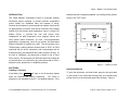
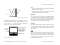
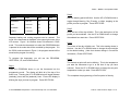
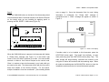
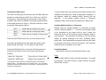
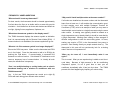
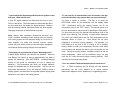
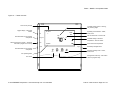
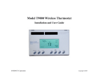
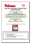
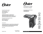
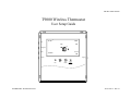
Pub No. 12401-012210 T9000 Wireless Thermostat User Setup Guide 11: 20 AM F/C COOL Th OFF Day O Program Run Set Point Fan Auto 70 O Light Clock Fan ENERNET Corporation Up Down Heat Cool Copyright 2010 ENERNET CORPORATION IS NOT RESPONSIBLE FOR ANY RADIO OR TV INTERFERENCE CAUSED BY UNAUTHORIZED MODIFICATIONS TO THIS EQUIPMENT. SUCH MODIFICATIONS COULD VOID THE USER’S AUTHORITY TO OPERATE THE EQUIPMENT. ENERNET CORPORATION PROVIDES THIS PUBLICATION “AS IS” WITHOUT WARRANTY OF ANY KIND, EITHER EXPRESS OR IMPLIED, INCLUDING, BUT NOT LIMITED TO, THE IMPLIED WARRANTIES OF MERCHANTABILITY OR FITNESS FOR A PARTICULAR PURPOSE. THIS EQUIPMENT COMPLIES WITH PART 15 OF THE FCC RULES. OPERATION IS SUBJECT TO THE FOLLOWING TWO CONDITIONS: (1) THIS DEVICE MAY NOT CAUSE HARMFUL INTERFERENCE, AND (2) THIS DEVICE MUST ACCEPT ANY INTERFERENCE RECEIVED, INCLUDING INTERFERENCE THAT MAY CAUSE UNDESIRED OPERATION. THIS MANUAL MAY CONTAIN TECHNICAL INACCURACIES AND/OR TYPOGRAPHICAL ERRORS. CHANGES ARE PERIODICALLY MADE TO THIS MANUAL, WHICH ARE INCORPORATED IN LATER EDITIONS. THE ORIGINAL EQUIPMENT MANUFACTURER (OEM) MUST ENSURE THAT FCC LABELING REQUIREMENTS ARE MET. THIS INCLUDES A CLEARLY VISIBLE LABEL ON THE OUTSIDE OF THE FINAL PRODUCT ENCLOSURE THAT DISPLAYS THE FOLLOWING: CONTAINS FCC ID: TGD12400/IC: 6120A-12400 ENERNET CORPORATION MAY MAKE CHANGES AND IMPROVEMENTS TO THE PRODUCT(S) AND/OR PROGRAMS DESCRIBED IN THIS PUBLICATION AT ANY TIME WITHOUT NOTICE. IN NO EVENT WILL ENERNET CORPORATION BE LIABLE FOR DAMAGES, INCLUDING LOST PROFITS, LOST SAVINGS OR OTHER INCIDENTAL OR CONSEQUENTIAL DAMAGES ARISING OUT OF THE USE OF OR INABILITY TO USE SUCH PRODUCT, EVEN IF ENERNET CORPORATION OR AN APPROVED RESELLER HAS BEEN ADVISED OF THE POSSIBILITY OF SUCH DAMAGES, OR FOR ANY CLAIM BY ANY OTHER PARTY. E N E R N E T Corporation 307 Dewittshire Road, Syracuse, New York 13214 Phone: (315) 449-0839 Fax: (315) 449-3056 T9000 — MODEL 124 Operation Guide INTRODUCTION batteries become completely depleted, the heating/cooling system The T9000 Wireless Temperature Control is a two-part wireless will go to the” OFF” state. thermostat system designed to provide precision temperature control without the installation labor and expense of wiring. Powered by AA batteries, the thermostat can operate continuously for approximately 18 months, and can be mounted in any suitable location that will provide good temperature control. A large LCD display (Figure 1) provides the user with current room 11: 20 F/C COOL Th OFF Day O Program temperature, set point temperature, time, program interval, and other system status information. (In hotel / non-programmable applications, programming, clock set up buttons and associated Run Set Point O Fan Auto Fan 70 Clock Light display information is typically not used.) The second part of the Fan T9000 system is called a Remote Control Node or “RCN”. An RCN Up Down Heat Cool interfaces with the HVAC equipment, and communicates with its thermostat using unlicensed 900 MHz, radio frequency energy. At the time of installation, the thermostat is linked to one or more RCN controls. The thermostat and RCN that have been linked will not interfere with, or be affected by any other thermostat or RCN in adjacent rooms, apartments, or neighboring homes. Figure 1 — T9000 Front View BATTERIES Replacing Batteries Installing / Changing A low battery icon - + will light on the thermostat display when the batteries are nearing exhaustion. The T9000 is designed to use standard AA size 1.5 volt alkaline batteries. If the © 2010 ENERNET Corporation • www.enernetcorp.com • 315-449-0839 To open the thermostat, use both hands, press the two push-tabs on the bottom of the thermostat housing with your thumbs while pulling the front of the thermostat away from the base - Figure 2. Pub No. 12401-012210 / Page 3 of 16 T9000 — MODEL 124 Operation Guide Note: Do not mix old and new batteries. When batteries are changed, replace them all at the same time. Front Cover Base Plate Programmed data for heating, cooling and time of day will be retained when batteries are removed or depleted. Latches MOUNTING Find a suitable location for mounting your thermostat, preferably Figure 2 — Opening Thermostat an interior wall, centrally located within the conditioned space at about 5' above the floor. Try not to locate the thermostat in a place where it could be exposed to heat such as warm air vents or The T9000 operates with either 2 or 4 AA batteries. Four (4) in a place where it could be exposed to direct sunlight. batteries double the time between battery changes (the average user can expect 1 to 1.5 years of battery life). Batteries are paired, one set on top of the other (see Figure 3). Wall-Mount The T9000 back mounting plate provides six (6) mounting holes. The upper and lower holes on the vertical centerline will match up Thermostat opened back Circuit Board Set A Set A Set B Set B Thermostat will operate on either Set A, Set B or both. When changing, replace with all new batteries. Never use a mix of old and new. Battery orientation is critical. with screw positions of a standard electrical switch box or drywall mounting ring. Step 1 Remove the back plate from the thermostat housing, (Figure 2) and use it to mark locations for mounting holes. While operation of the thermostat is not affected by orientation, we recommend using a level across the top or side of the base plate to ensure a Figure 3 — Battery Location © 2010 ENERNET Corporation • www.enernetcorp.com • 315-449-0839 professional installed appearance. Pub No. 12401-012210 / Page 4 of 16 T9000 — MODEL 124 Operation Guide Step 2 COOL Drill 3/8” holes and insert drywall fasteners (#6 screws recommended) and fasten the back plate to the wall. Mode of operation O Back Stand Set Point Fan status Located on the back of the housing is a built-in hinged stand support. This feature permits the thermostat to stand on a flat surface such as a table or shelf, in the event that permanent mounting to a wall is not desired. Fan Auto 70 O Set Point Figure 5 — General Operation Display Four buttons located on the left side of the thermostat (Figure 1) control display of temperature in either Fahrenheit or Celsius, programming, clock setup and control of whether the thermostat is BUTTONS A four button cluster is located on the front of the T9000. Fan Up Down Heat Cool Figure 4 — Front Button Cluster under manual or program control. F / C - Toggles Fahrenheit Celsius display Program set up button Run – Sets program or manual mode of operation Clock set up button These buttons are used in adjusting fan operation, changing the BACKLIGHT set point temperature up or down and changing the operating A single button on the right side of the thermostat activates the mode of the thermostat. (Figure 13 provides definition of all button display backlight. When pressed, the backlight will illuminate the and display items.) display briefly and turn off. Figure 5 shows the display items that are changed by these four buttons in normal operation. If other buttons are pressed immediately after the backlight button, the display will stay illuminated until a few seconds after all button activity has ended. Note that the UP, DOWN and HEAT/COOL buttons are also used Backlighting takes significant energy from the batteries and should in setting the clock, programming the thermostat and linking to be used sparingly. nodes — covered later in this manual. noticeably reduce battery life. © 2010 ENERNET Corporation • www.enernetcorp.com • 315-449-0839 Frequent use of the backlight function will Pub No. 12401-012210 / Page 5 of 16 T9000 — MODEL 124 Operation Guide — IF USING A NON-PROGRAMMABLE MODEL THERMOSTAT — PLEASE SKIP THE CLOCK AND PROGRAMMING SECTIONS. CONTINUE ON PAGE 9 INSTALLING AND REMOVING NODES Step 3 One of the seven day icons (Mo, Tu, We, Th, Fr, Sa, Su) will now blink, press UP or DOWN until the correct day icon is displayed and press HEAT/COOL. SETTING THE CLOCK Step 4 In all set up modes the T9000 will blink the display item you are about to change. The UP and DOWN buttons change settings, the HEAT/COOL button is used to move to the next item. To set the clock, you will use the buttons marked CLOCK, UP, Press the CLOCK button to keep all clock changes you've made and resume normal operation. THERMOSTAT PROGRAMMING The T9000 provides four program periods: Morning, Day, Evening, DOWN, and HEAT/COOL. and Night. The time and temperature can be set for each period. Upon initial power up the T9000 loads time and temperature Step 1 Press the CLOCK Button. The hour digits will blink. Press the UP or DOWN button to change the hour. Note that AM / PM will program default parameters for weekday and weekend days. The default program parameters conform to Energy Star change as you roll the hour past 12. Be sure to set the hour guidelines and are a good point from which to start. properly for AM or PM. Press the HEAT/COOL button to keep the settings are: hour you've just set and to move to minutes. WEEKDAY DEFAULT PROGRAM TIMES AND TEMPERATURES Period Time Heat Cool MORNING 6:00 AM 70 75 button to change to the desired minute. When the correct minute DAY 8:00 AM 62 83 is flashing press HEAT/COOL. EVENING 6:00 PM 70 75 NIGHT 10:00 PM 62 78 Step 2 The Minute digits will now be blinking. Press the UP or DOWN © 2010 ENERNET Corporation • www.enernetcorp.com • 315-449-0839 Default Pub No. 12401-012210 / Page 6 of 16 T9000 — MODEL 124 Operation Guide WEEKEND DEFAULT PROGRAM TIMES AND TEMPERATURES Step 2 Period Time Heat Cool Next the Morning period will blink. Use the UP or DOWN button to MORNING 8:00 AM 70 75 toggle through Morning, Day, Evening, or Night, stopping at the DAY 10:00 AM 62 83 EVENING 6:00 PM 70 75 NIGHT 11:00 PM 62 78 period you want to program. Press HEAT/COOL. Step 3 Next, the hour of the day will blink. This is the starting hour of the period you have selected. Use the UP or DOWN button to change Separate heating and cooling programs can be entered. The the selected hour start time. Press HEAT/COOL. mode of the thermostat is displayed in the upper right corner of the LCD screen. Figure 1 for instance shows a thermostat in COOL mode. The mode the thermostat is in when the PROGRAM button is pressed is the mode that will be controlled by that program. If in the COOL mode as shown in Figure 1, the program entered will be stored as the program for cooling. To program the thermostat, you will use the PROGRAM, HEAT/COOL, UP, and DOWN buttons. Step 1 Press the PROGRAM button to put the thermostat into the Step 4 The minute of the day will blink next. This is the starting minute in the hour. Use the UP or DOWN button to change the minute digits to the desired setting. (Note that minutes change in five-minute increments.) Press HEAT/COOL. Step 5 The desired set point will now be blinking. This is the temperature you want the thermostat to go to at the time of day you have selected. Press the UP or DOWN button to change the set point temperature to what you want. Press HEAT/COOL. programming mode. The display will blink all of the day of the week icons. Pressing the UP or DOWN button will toggle between This completes the programming of the first period of the day. (weekday) icons and the (weekend) icons. Ensure the display is blinking the days you want to program. Press HEAT/COOL. © 2010 ENERNET Corporation • www.enernetcorp.com • 315-449-0839 Pub No. 12401-012210 / Page 7 of 16 T9000 — MODEL 124 Operation Guide Step 6 RUN BUTTON – Program / Manual Operation If you started with the Morning time period, the next period, Day, The RUN button toggles the thermostat between manual operating will now be blinking. Follow steps two, three, four, and five above mode and program operating mode. When in the program mode for each period you wish to program. your thermostat responds to the times and temperatures programmed. NAVIGATING You can quickly step through to a specific item you want to change Figure 6 shows a thermostat running in program mode. One of by pressing the HEAT/COOL button until what you want to change the four periods, in this case “Day”, is displayed, letting you know is flashing. When the item you want to change is flashing, use the which period of the day the program is in. When in manual mode UP or DOWN button to adjust. as shown in Figure 7, the period of the day is not displayed. Instead, the word “Hold” will be displayed above the Set Point EXITING PROGRAM MODE temperature, indicating the thermostat is holding that temperature. Pressing the PROGRAM button at anytime will exit out of the programming mode, save your changes to memory and return you In manual mode you can adjust to the desired temperature using to normal thermostat operation. the UP and DOWN buttons, and the thermostat will maintain that temperature until you change it again. 11: 20 AM HEAT Th Day 11: 20 AM O HEAT Th OFF Set Point Fan Auto 71 O Hold Set Point Figure 6 – Program Mode Display Fan Auto 70 O Figure 7 – Manual Mode Display © 2010 ENERNET Corporation • www.enernetcorp.com • 315-449-0839 Pub No. 12401-012210 / Page 8 of 16 T9000 — MODEL 124 Operation Guide CHANGING TEMPERTATURE WHILE RUNNING A PROGRAM thermostat to it’s RCN(s) if the thermostat batteries are replaced or You can always change the temperature up or down while a after a power outage. program is running. However, when the program moves to the next period, the programmed set point temperature for that period Installing Nodes will take effect. For instance, assume the current program period If multiple installation teams are installing and linking is Evening, with a programmed temperature of 70°, and the next thermostats at the same time, coordinate the activity to avoid period, Night, is programmed for 65°, scheduled to start at 11:00 the possibility of installers simultaneously attempting to PM. If during the Evening time period you desired the space to be perform the linking process. Because this is an RF system, warmer, you could press the UP button to raise the temperature installers in nearby rooms where it is possible RF overlap set point. The thermostat will hold that temperature until the next could exist run the risk of interfering with each other. program period, at which point the temperature will adjust to the Installation and linking activity going on around a system programmed temperature set point for that period. In this case the already installed will not interfere with it. Night period is set for 11:00 PM and 65°. Refer to Figure 8 for inside thermostat button and jumper locations INSTALLING AND REMOVING NODES A T9000 thermostat and Remote Control Node will not operate as a system until they are linked together through the installation process. The linking process binds one or more control nodes to a thermostat so that they will communicate with each other as a control system. Up to eight nodes can be linked to a single thermostat. Until linked, a control node will not operate. Once linked, a control node will only respond to its specific thermostat. The thermostat and RCN that have been linked will not interfere with or be affected by any other thermostat or RCN in adjacent and functions. Step 1 Press the SW4-INSTALL button inside the thermostat. The display will change to the Install Session screen shown in Figure 9, with the ‘Install’ Icon blinking. Note: The display always blinks the item that is active and can be changed. rooms, apartments, or neighboring homes. Linking information is stored in non-volatile memory — It is not necessary to re-link the © 2010 ENERNET Corporation • www.enernetcorp.com • 315-449-0839 Pub No. 12401-012210 / Page 9 of 16 T9000 — MODEL 124 Operation Guide Internal T9000 buttons SW12-RESET SW4-INSTALL SW9-LINK Press HEAT/COOL to select Install. PB1-NETWORK PB1-NETWORK Used to uninstall the thermostat from node(s) it has been linked to. HEAT COOL SW12-RESET Master Reset – Returns thermostat to all factory defaults. JP3 - Program Install Node SW4-INSTALL Starts an installation session. JP4 – Non Program Set A Set A Set B Set B SW9-LINK Used to Link the thermostat to control nodes. Figure 9 – Install Setup Display Step 3 The node number digits will now flash. Use the UP button to set SW12-RESET SW9-LINK JP3 = Programmable JP4 = Non-Programmable number 0 – 7. If this is the first node or only node to be installed to this thermostat leave the node number at zero. PB1-NETWORK Program Jumper SW4-INSTALL Press the HEAT/COOL button to select the node number. Step 4 Figure 8 – Internal Buttons Step 2 The UP button on the front of the thermostat is used to toggle between the following two choices: Install — Install a Node Remove — Uninstall ALL Nodes (The Remove option will be discussed later.) © 2010 ENERNET Corporation • www.enernetcorp.com • 315-449-0839 After selecting the node number, the HEAT and COOL icon will flash in the upper right hand corner of the display (Figure 9). No change is needed when installing the model 122 RCN. Press the HEAT/COOL button. At this point all selections have been made and nothing on the display should be blinking. You are now ready to install a node. Pub No. 12401-012210 / Page 10 of 16 T9000 — MODEL 124 Operation Guide Step 5 note on page 9.) Press the SW9-LINK button on the back of the thermostat printed information is exchanged, the “Please Wait” message is circuit board and within 5-seconds activate a Link Service Request extinguished and a “Good” message will appear as shown in on the control node you are installing by applying power or Figure 11. Once the thermostat finds its node, linking pressing the PB3, RESET / LINK button (Figure 10). Install Node Network Microcontroller 916.5 MHz PB3 Transceiver HEAT COOL D5 RESET / LINK G1 D3 D4 PB1 G2 HEAT COOL G3 O/B W Please Wait Y Install Node Good Output Indicators PB2 CONFIG G1 G2 G3 W O/B Y C R Figure 11 – Install - Link Display Figure 10 – Model 122 PTAC Wireless Control Node If another node is to be installed to this thermostat, press the When the SW9-LINK button is pressed, the thermostat will display HEAT/COOL button again. The ‘Install’ icon will flash. As was a “Please Wait” message (see Figure 11) in the bottom right done previously press the HEAT/COOL button (Step Two). The corner of the LCD while it searches for a node. You have several node number will begin blinking, increment the number by one seconds to initiate a Link Service Request at the control node. using the UP button and continue with the remaining steps. When Often it is easiest to have the thermostat in your hand while you all nodes are installed press the SW4-INSTALL button to close the are near by the node. The thermostat will link with the first node it installation session and return to normal thermostat operation. hears that initiates a Link Service Request. For this reason, multiple installations must be coordinated. (See Installing Nodes © 2010 ENERNET Corporation • www.enernetcorp.com • 315-449-0839 Pub No. 12401-012210 / Page 11 of 16 T9000 — MODEL 124 Operation Guide Linking Other Node Types If for any reason there was a problem encountered during the final The model 103 wall-plug node and the model 105 JBOX node can installation and linking step, a “Bad” message will be displayed. If be linked to a thermostat as a HEAT only, COOL only or HEAT & this happens, repeat the ‘Installing Nodes’ process from the COOL control. After selecting the node number in step 3 above, beginning. the HEAT and COOL icon will flash in the upper right hand corner Installation Reset’ (covered later) and repeat the install process. If the problem persists, perform a ‘Thermostat of the display as shown in Figure 9. Press the UP button to scroll through the following three choices: HEAT — Install node as a heating only control COOL — Install node as a cooling only control HEAT COOL — Install node as a heating & cooling control Installing Multiple Nodes to a Thermostat Multiple nodes are typically installed to a thermostat by linking each as a different number 0 – 7. If a node is not sending a signal to the thermostat for any reason such as loss of power, the thermostat will turn off the antenna symbol indicating a break in communication. The thermostat will attempt to find the missing Press the HEAT/COOL button when you have what you want. node(s) by sending messages more often, increasing battery power drain. Some applications may warrant linking all the nodes At this point all selections have been made and nothing on the as the same node number, node 00 for instances. See Frequently display should be blinking. You are ready to install a node. Asked Questions for guidance on this topic. Press the SW9-LINK button on the back of the thermostat and Uninstalling Nodes activate a Link Request on the control node by the following The procedure to remove will uninstall all nodes at once. methods: Model 103 - Plug Node Plug unit into a 115vac outlet* Model 105 - JBOX Node Apply Power or press PB1* * The model 103 Plug node does not provide access to a Link Service Request button. The JBOX RCN is a line-voltage device. Only a qualified technician should open the enclosure to access PB1. All others should use the power up method only. © 2010 ENERNET Corporation • www.enernetcorp.com • 315-449-0839 Step 1 Press the SW4-INSTALL button inside the thermostat. The Install Icon will flash. Press the UP button, to select ‘Remove’ and press HEAT/COOL to select. Pub No. 12401-012210 / Page 12 of 16 T9000 — MODEL 124 Operation Guide Step 2 pressed). Press the SW9-LINK button in the thermostat. Within 5-seconds effect. Otherwise, the PB1-NETWORK button will have no activate a Link Service Request on any control node linked to the thermostat. “Please Wait” message (see Figure 11) is displayed Note: while linking information is removed, the “Good” message appears A thermostat that does not have a node linked to it will display when complete (Figure 11). “Install Node” when in normal operation mode (Figure 12). Once a node is linked to the thermostat, this message will no longer be Thermostat Installation Reset displayed. If you repeatedly have difficulty linking a node, perform the following: Step 1 11: 20 Press the SW4-INSTALL button inside the thermostat. The Install Icon will flash. You only need to begin the installation session to F/C COOL Th O Install Mode perform this reset. Run Step 2 OFF Day Program Set Point O Fan Auto 70 Light Clock Press and hold the PB1-NETWORK button (see Figure 8) on the Fan Up Down Heat Cool inside of the thermostat board for approximately two seconds. No response is displayed while in the Install Session screen, however, all previous installation records will be wiped from thermostat memory. You can continue from this point with the installation procedure. PB1-NETWORK will only reset the thermostat installation database when the thermostat is in the Figure 12 – unlinked Display Installation Session screen (SW4-INSTALL button has been © 2010 ENERNET Corporation • www.enernetcorp.com • 315-449-0839 Pub No. 12401-012210 / Page 13 of 16 T9000 — MODEL 124 Operation Guide FREQUENTLY ASKED QUESTIONS “Where should I locate my thermostat?” For best results, the thermostat should be located approximately five feet above the floor on an inside wall in an area with good air circulation. Avoid drafts from air ducts and windows and heat from sun light, lighting fixtures, appliances, fireplaces, etc. “What does the antenna symbol on the display mean?” “Why would I install multiple nodes as the same number?” If all nodes are installed as the same number and the thermostat hears from at least one, it will consider the communication good. A hotel meeting room with multiple Packaged Terminal Air Conditioner (PTAC) units is an example of when you may want to install multiple control nodes to a single thermostat using the same node number. A meeting room typically should be treated as a single temperature zone; thereby ideally it should be controlled by The T9000 thermostat displays the antenna symbol as indication a single thermostat. Meeting room seating is often arranged in that it is communicating with its Remote Control Node (RCN). If different configurations to suite the event taking place. At times, communication is not established, the antenna symbol will go out. seating may require a PTAC to be disconnected from power to prevent it from blowing directly on people seated close by. The “What do I do if the antenna symbol is no longer displayed?” thermostat in this case will not continuously look for a missing Ensure the RCN has power. Make sure the thermostat and RCN node if that one unit is powered off. are in fact linked. Force the thermostat to talk to its RCN(s) by pushing the FAN button. If communication is successful the “When my a/c turns off, I can’t immediately make it run antenna icon will turn back on. Coincidental RF interference could again?” cause a temporary loss of communication. In virtually all such This is normal. What you are experiencing is called an anti short- cases, the interference is temporary. cycle delay. Because of high pressure in the air conditioning compressor system, it’s not a good idea to start your air “Can I run multiple heating or cooling loads such as electric conditioner immediately after it has just shut down. The T9000 baseboard heating and a window air conditioner with one prevents this from happening by imposing a 3-minute delay. T9000 thermostat?” Yes. In fact one T9000 thermostat can control up to eight (8) RCNs with each being given different node numbers. © 2010 ENERNET Corporation • www.enernetcorp.com • 315-449-0839 Pub No. 12401-012210 / Page 14 of 16 T9000 — MODEL 124 Operation Guide “I just installed the thermostat and the antenna symbol comes “If I am away for an extended time such as vacation, how do I and goes. What should I do?” set the thermostat so my system does not run excessively?” A poor RF signal between the thermostat and one or more You have a couple of choices. RCN’s is the cause. The further away the thermostat and RCN HEAT/COOL button on the thermostat until the display reads are from each other, the weaker the signal becomes. Distance “OFF." (Particularly during the heating season, we do not and also building material, particularly metal may block signals. recommend going to the “OFF” mode.) The second option is to Changing the position of the thermostat may help. put your thermostat in manual mode by pressing the RUN button. The first is to press the You know that you are in the manual mode because none of the Note: Always seek competent professional electrical and period icons, Morning, Day, Evening, or Night will be displayed. HVAC contractor assistance when working with your heating The ‘Hold” icon located above the Set Point temperature will be and cooling system and the electrical wiring in your home or displayed (Refer to Figure 7). other property. For safety and warranty reasons, always temperature to minimize system operation. consult with your HVAC contractor and the original equipment could adjust to a set point of 85º in cooling or 65º in heating, manufacturer before making changes to the equipment. staying mindful of what your temperature selection could affect Next, adjust the set point For example, you such as plants and animals that stay in your home while you are “The display on my thermostat is blank. What happened?” away. During the cooling season, consider humidity as well as A blank display indicates your batteries are depleted. When the indoor temperature. When your air conditioner runs it not only Low Battery icon comes on there is approximately one week of cools the air, it also removes moisture, lowering humidity. High battery life remaining. humidity can encourage mold growth. (See BATTERIES - Installing/Changing section of this guide for information on how to change the batteries.) We recommend that when you change batteries, “Can I use another T9000 thermostat without interference?” always use batteries that you know are fresh. Use four (4) new Yes. A T9000 thermostat and its RCN(s) will talk between high quality AA batteries. If you are using the T9000 to control a themselves, but will never respond to or control another heating system, we recommend as a general practice putting fresh thermostat in adjacent rooms, apartments, or neighboring homes. batteries in at the start of the heating season. © 2010 ENERNET Corporation • www.enernetcorp.com • 315-449-0839 Pub No. 12401-012210 / Page 15 of 16 T9000 — MODEL 124 Operation Guide Figure 13 — T9000 Overview Time and day of week Indicates program period – Morning, Day, Evening, Night Toggles display - Fahrenheit Celsius 11: 20 AM F/C Puts thermostat into the program setup mode Starts and stops the program – Holds Set Point when program is not running OFF Day RF connection with a control node O Program Run Operating mode indication - HEAT, COOL, OFF COOL Th Indicates holding of Set Point temperature – See Run button Hold Set Point Fan Auto 70 O Current Set Point temperature Light Clock Puts thermostat into the program setup mode Fan Up Down Heat Cool Momentary backlight button Changes operating mode – HEAT, COOL, OFF Fan operating status Fan control © 2010 ENERNET Corporation • www.enernetcorp.com • 315-449-0839 Changes Set Point temp - Also used in clock and program setup Pub No. 12401-012210 / Page 16 of 16