1
USER’
USER’S MANUAL
LG PROGRAMMABLE LOGIC CONTROLLER
GLOFA-GM
Instruction / Programming
LG Industrial Systems
Table of Contents
Ch 1. Overview
1.1. Characteristics of IEC 1131-3 Language .........................................................1-1
1.2. Type of Language ..............................................................................................1-1
Ch 2. The Structure of Software
2.1. Overview...............................................................................................................2-1
2.2. Project ..................................................................................................................2-1
2.3. Configuration ........................................................................................................2-1
2.3.1. Resource ...................................................................................................2-2
2.3.1.1. Program ..........................................................................................2-2
2.3.1.2. Resource Global Variable ...............................................................2-2
2.3.1.3. Task ................................................................................................2-3
2.3.2. Configuration Global Variable ....................................................................2-4
2.3.3. Access Variable .........................................................................................2-4
Ch 3. Common Elements
3.1. Expression............................................................................................................3-1
3.1.1. Identifiers ...................................................................................................3-1
3.1.2. Data Expression ........................................................................................3-1
3.1.2.1. Numbers .........................................................................................3-2
3.1.2.2. Character String ..............................................................................3-2
3.1.2.3. Time Letters ....................................................................................3-2
3.1.2.3.1. Duration.................................................................................. ..... 3-2
3.1.2.3.2. Time of Day and Date ............................................................ ..... 3-3
3.2. Data Type .............................................................................................................3-4
3.2.1. Basic Data Type.........................................................................................3-4
3.2.2. Data Type Hierarchy Chart ........................................................................3-5
3.2.3. Initial Value ................................................................................................3-5
3.2.4. Data Type Structure...................................................................................3-6
3.3. Variable ................................................................................................................3-8
3.3.1. Variable Expression...................................................................................3-8
3.3.2. Variable Declaration...................................................................................3-9
3.3.3. Reserved Variable........................................................................................... 3-12
I
Table of Contents
3.4. Reserved Word ..................................................................................................3-17
3.5. Program Type.....................................................................................................3-18
3.5.1. Function ...................................................................................................3-18
3.5.2. Function Block .........................................................................................3-19
3.5.3. Program ...................................................................................................3-20
Ch 4. SFC (Sequential Function Chart)
4.1. Overview...............................................................................................................4-1
4.2. SFC Structure.......................................................................................................4-1
4.2.1. Step............................................................................................................4-1
4.2.2. Transition ...................................................................................................4-2
4.2.3. Action .........................................................................................................4-2
4.2.4. Action Qualifier ..........................................................................................4-3
4.3. Extension Regulation............................................................................................4-8
4.3.1. Serial Connection.......................................................................................4-8
4.3.2. Selection Branch........................................................................................4-8
4.3.3. Parallel Branch (Simultaneous Branch).....................................................4-9
4.3.4. Jump ..........................................................................................................4-9
Ch 5. IL (Instruction List)
5.1. Overview ............................................................................................................5-1
5.2. Current Result: CR.............................................................................................5-1
5.3. Instructions.........................................................................................................5-2
5.3.1. Label........................................................................................................5-2
5.3.2. Modifier....................................................................................................5-2
5.3.3. Basic Operation.......................................................................................5-3
5.3.3.1. Basic Operator..............................................................................5-5
5.4. Calling of Function and Function Block............................................................5-24
II
Table of Contents
Ch 6. LD (Ladder Diagram)
6.1. Overview...............................................................................................................6-1
6.2. Bus Line................................................................................................................6-1
6.3. Connection Line....................................................................................................6-2
6.4. Contact .................................................................................................................6-3
6.5. Coil .......................................................................................................................6-4
6.6. Calling of Function and Function Block ................................................................6-5
Ch 7. Function and Function Block
7.1. Function................................................................................................................7-1
7.1.1. Type Conversion Function .........................................................................7-1
7.1.2. Arithmetic Function ....................................................................................7-8
7.1.2.1. Numerical Operation Function with One Input ................................7-8
7.1.2.2. Basic Arithmetic Function ...............................................................7-8
7.1.3. Bit Array Function ......................................................................................7-9
7.1.3.1. Bit-shift Function .............................................................................7-9
7.1.3.2. Bit Operation Function ....................................................................7-9
7.1.4. Selection Function .....................................................................................7-9
7.1.5. Data Exchange Function ...........................................................................7-9
7.1.6. Comparision Function..............................................................................7-10
7.1.7. Character String Function........................................................................7-10
7.1.8. Time/Time of Day/Date and Time of Day Function .................................7-11
7.1.9. System Control Function .........................................................................7-11
7.1.10. Data Manipulation Function ...................................................................7-12
7.1.11. Stack Operation Function ......................................................................7-12
7.2. MK (MASTER-K) Function ...............................................................................7-13
7.3. Array Operation Function ...................................................................................7-13
7.4. Basic Function Block ..........................................................................................7-13
7.4.1. Bistable Function Block ...........................................................................7-13
7.4.2. Edge Detection Function Block................................................................7-13
7.4.3. Counter ....................................................................................................7-14
7.4.4. Timer........................................................................................................7-14
7.4.5. Other Function Block .................................................................................... 7-14
III
Table of Contents
Ch 8. Basic Function/Function Block Library
8.1 Basic Function Library.................................................................................................. 8-1
ABS .................................................................................................................8-2
ACOS ................................................................................................................8-3
ADD .................................................................................................................8-4
ADD_TIME ........................................................................................................8-5
AND...................................................................................................................8-6
ARY_TO_STRING ............................................................................................8-7
ASIN ..................................................................................................................8-8
ATAN.................................................................................................................8-9
BCD_TO_*** ...................................................................................................8-10
BOOL_TO_*** .................................................................................................8-11
BYTE_TO_***..................................................................................................8-12
CONCAT .........................................................................................................8-13
CONCAT_TIME ..............................................................................................8-14
COS.................................................................................................................8-15
DATE_TO_*** .................................................................................................8-16
DELETE ..........................................................................................................8-17
DI.....................................................................................................................8-18
DINT_TO_***...................................................................................................8-20
DIREC_IN........................................................................................................8-22
DIREC_O ........................................................................................................8-25
DIV ..................................................................................................................8-27
DIV_TIME........................................................................................................8-28
DT_TO_*** ......................................................................................................8-29
DWORD_TO_***.............................................................................................8-30
EI .....................................................................................................................8-32
EQ ...................................................................................................................8-33
ESTOP ............................................................................................................8-34
EXP .................................................................................................................8-35
EXPT ...............................................................................................................8-36
FIND ................................................................................................................8-37
GE ...................................................................................................................8-38
GT ...................................................................................................................8-39
INSERT ...........................................................................................................8-40
INT_TO_*** .....................................................................................................8-41
LE ....................................................................................................................8-43
LEFT................................................................................................................8-44
LEN .................................................................................................................8-45
LIMIT ...............................................................................................................8-46
LINT_TO_*** ..............................................................................................8-47
IV
Table of Contents
LN ...............................................................................................................8-49
LOG ............................................................................................................8-50
LREAL_TO_***...........................................................................................8-51
LT ...............................................................................................................8-53
LWORD_TO_***.........................................................................................8-54
MAX............................................................................................................8-56
MID .............................................................................................................8-57
MIN .............................................................................................................8-58
MOD ...........................................................................................................8-59
MOVE .........................................................................................................8-60
MUL ............................................................................................................8-61
MUL_TIME .................................................................................................8-62
MUX ...........................................................................................................8-63
NE
...........................................................................................................8-64
NOT ............................................................................................................8-65
NUM_TO_STRING.....................................................................................8-66
OR..............................................................................................................8-67
REAL_TO_***.............................................................................................8-68
REPLACE...................................................................................................8-70
RIGHT ........................................................................................................8-72
ROL ............................................................................................................8-73
ROR ...........................................................................................................8-74
SEL.............................................................................................................8-75
SHL.............................................................................................................8-76
SHR ............................................................................................................8-77
SIN..............................................................................................................8-78
SINT_TO_*** ..............................................................................................8-79
SQRT .........................................................................................................8-81
STOP..........................................................................................................8-82
STRING_TO_***.........................................................................................8-83
STRING_TO_ARY .....................................................................................8-85
SUB ............................................................................................................8-86
SUB_DATE ................................................................................................8-87
SUB_DT .....................................................................................................8-88
SUB_TIME .................................................................................................8-89
SUB_TOD ..................................................................................................8-90
TAN ............................................................................................................8-91
TIME_TO_***..............................................................................................8-92
TOD_TO_***...............................................................................................8-93
TRUNC.......................................................................................................8-94
UDINT_TO_*** ...........................................................................................8-95
UINT_TO_*** .............................................................................................8-97
V
Table of Contents
ULINT_TO_***......................................................................................................8-99
USINT_TO_*** ...................................................................................................8-101
WDT_RST..........................................................................................................8-103
WORD_TO_***...................................................................................................8-105
XOR ..................................................................................................................8-106
8.2 Application Function Library ..................................................................................... 8-107
ARY_ASC_TO_BCD ..........................................................................................8-108
ARY_ASC_TO_BYTE ........................................................................................8-110
ARY_AVE_***.....................................................................................................8-112
ARY_BCD_TO_ASC ..........................................................................................8-114
ARY_BYTE_TO_ASC ........................................................................................8-116
ARY_CMP_*** ....................................................................................................8-118
ARY_FLL_***......................................................................................................8-120
ARY_MOVE........................................................................................................8-122
ARY_ROT_C_***................................................................................................8-124
ARY_SCH_*** ....................................................................................................8-126
ARY_SFT_C_*** ................................................................................................8-128
ARY_SWAP_*** .................................................................................................8-130
ASC_TO_BCD ...................................................................................................8-132
ASC_TO_BYTE..................................................................................................8-133
BCD_TO_ASC ...................................................................................................8-134
BIT_BYTE ..........................................................................................................8-135
BMOV_***...........................................................................................................8-136
BSUM_*** ...........................................................................................................8-138
BYTE_BIT ..........................................................................................................8-139
BYTE_TO_ASC..................................................................................................8-140
BYTE_WORD ....................................................................................................8-141
DEC_***..............................................................................................................8-142
DECO_***...........................................................................................................8-143
DEG_*** .............................................................................................................8-144
DIS_*** ...............................................................................................................8-145
DWORD_LWORD..............................................................................................8-147
DWORD_WORD................................................................................................8-148
ENCO_B,W,D,L .................................................................................................8-149
GET_CHAR........................................................................................................8-150
INC_B,W,D,L......................................................................................................8-151
LWORD_DWORD..............................................................................................8-152
MCS ...................................................................................................................8-153
MCSCLR ............................................................................................................8-155
MEQ ...................................................................................................................8-156
PUT_CHAR ........................................................................................................8-158
VI
Table of Contents
RAD_*** ..............................................................................................................8-159
ROTATE_A_*** ..................................................................................................8-160
ROTATE_C_*** ..................................................................................................8-163
RTC_SET ...........................................................................................................8-165
SEG ....................................................................................................................8-168
SHIFT_A_***.......................................................................................................8-170
SHIFT_C_*** ......................................................................................................8-173
SWAP_***...........................................................................................................8-175
UNI_*** ...............................................................................................................8-176
WORD_BYTE.....................................................................................................8-178
WORD_DWORD................................................................................................8-179
XCHG_*** ...........................................................................................................8-180
8.3 Basic Function Block Library .....................................................................................8-182
CTD ....................................................................................................................8-183
CTU ....................................................................................................................8-185
CTUD..................................................................................................................8-187
F_TRIG...............................................................................................................8-189
RS .......................................................................................................................8-190
R_TRIG ..............................................................................................................8-191
SEMA..................................................................................................................8-192
SR .......................................................................................................................8-195
TOF ....................................................................................................................8-196
TON ....................................................................................................................8-198
TP .......................................................................................................................8-200
8.4 Application Function Block Library ............................................................................8-202
CTR ....................................................................................................................8-203
DUTY ..................................................................................................................8-205
FIFO_*** .............................................................................................................8-207
LIFO_***..............................................................................................................8-211
SCON .................................................................................................................8-215
TMR....................................................................................................................8-218
TMR_FLK ...........................................................................................................8-220
TMR_UINT .........................................................................................................8-222
TOF_RST ...........................................................................................................8-224
TOF_UINT ..........................................................................................................8-226
TON_UINT..........................................................................................................8-228
TP_RST ..............................................................................................................8-230
TP_UINT.............................................................................................................8-232
TRTG..................................................................................................................8-234
TRTG_UINT .......................................................................................................8-236
VII
1. Overview
1. Overview
This instruction describes languages that support GM1~GM7 (GLOFA PLC).
GLOFA PLC is based on the standard language of IEC (International Electrotechnical Commission).
1.1 Characteristics of IEC 1131-3 Language
The characteristics of IEC language newly introduced are as follows:
▷
Available to support several data types.
▷
The introduction of program elements such as functions, function blocks etc. enables the bottomup design and top-down design and the structural creation of PLC program.
▷
The program created by the user shall be stored like as a library system so that it can be used in
other environment, which enables to reuse the software.
▷
Available to support various languages so that the user can select the optimal language suitable for
the environment to apply.
1.2 Type of Language
The PLC language standardized by IEC consists of two illustrated languages, two character languages
and SFC.
▷
Illustrated languages
a) LD (Ladder Diagram): A graphical language that is based on the relay ladder logic
b) FBD (Function Block Diagram): A graphical language for depicting signal and data flows through
function blocks - re-usable software elements
▷
Character language
a) IL (Instruction List): A low-level 'assembler like' language that is based on similar instruction list
languages.
b) ST (Structured Text): A high-level language of PASCAL type
▷
SFC (Sequential Function Chart): A graphical language for depicting sequential behavior of a
control system. It is used for defining control sequences that are time- and event-driven.
1-1
1. Overview
The languages supported by GLOFA PLC at present are IL, LD and SFC.
Choose the language to use
1-2
2. The Structure of Software
2. The Structure of Software
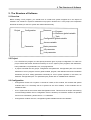
2.1 Overview
Before making a PLC program, you should have an overall PLC system mapped out in the aspect of
software. The overall PLC system is defined as one project in GLOFA PLC. In the project, all composition
elements necessary for the PLC system are defined hierarchically.
Project
Configuration
Resource
Program
Resource global variable
Task
Configuration global variable
Access variable
Parameter
Basic parameter
I/O parameter
Link parameter
2.2 Project
▷
For a GLOFA PLC program, the first priority should be given to project configuration. To make one
project means that all the elements necessary for a PLC system (scan programs, task definitions,
basic parameters, I/O parameters, etc.) are programmed.
▷
A project is divided into two groups: configuration and parameter. Configuration part is for several
definitions of a PLC program such as global variable, program, task definition and their interrelation.
Parameter part is for setting parameters necessary for a PLC system operation. In this book, we
deal with “Configuration part.” For parameter part, please refer to “GMWIN User’s Manual.”
2.3 Configuration
▷
Configuration means a PLC system. It consists of a base, a CPU module, I/O modules and special
modules and so on. Generally one PLC system has one CPU module; 4 CPU modules can be
installed in GM1.
▷
A PLC system has its own name called Configuration name. This becomes its unique name during
communicating between PLCs. Configuration name is limited up to maximum 8 letters in alphabet
and for more information, please refer to 3.1.1 Identifiers.
▷
Configuration contains resource, configuration global variables and access variables.
2-1
2. The Structure of Software
2.3.1 Resource
▷
Resource means one CPU module. And it is available to define 4 resources in the GM1
Configuration. For GM2 ~ GM5, only one resource is available to define. This resource has its own
name that is also used for communication. The resource name is limited up to 8 letters in alphabet
and it complies with 3.1.1 Identifiers.
▷
Resource has programs, resource global variables and task definitions.
2.3.1.1 Program
▷
It is an application program that is actually executed on PLC. In GLOFA PLC, it is available to
create several application programs for one resource and set program conditions to run. For
example, you can make programs as follows: program A is a general scan program; program B is a
program executed once in a second; program C is an event program that is executed with certain
inputs. These conditions to execute the program are called “Task.” Users should make an
application program as well as set the conditions (task definitions). Unless task definitions are set,
this program will be regarded as a scan program.
Reference
Scan program: application program that repeats a series of execution from the start to the end after
reading input data from input modules, and writing the results in output modules.
▷
A program has its instance name. This instance contains data to be executed in this program.
Reference
For the instance, refer to 3.5.2. Function Block.
2.3.1.2 Resource Global Variable
▷
The variables defined in resource global variable can be used in any program of the resource. All
the data to be shared among programs are defined in resource global variables.
▷
If users want to use resource global variables in their programs, variables are supposed to be
declared as VAR_EXTERNAL.
Reference
For a variable type, refer to 3.3.2 Variable Declaration.
2-2
2. The Structure of Software
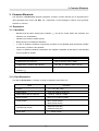
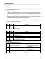
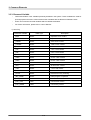
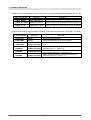
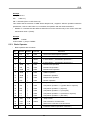
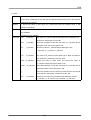
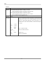
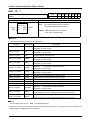
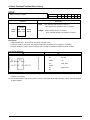
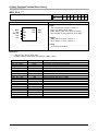
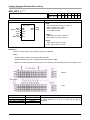
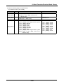
2.3.1.3 Task
▷
Task means a condition to execute a program. Task definitions contain designation of program
execution condition and priority.
▷
There are 3 types of program execution conditions as follows:
1) Single: executes once if the setting condition is satisfied. The condition is set as a name of
BOOL variable.
2) Interval: executes periodically per a setting time. The condition is set as elapsed time value.
Refer to ‘3.1.2.3.1 Duration’ for how to set the elapsed time value.
3)
Interrupt: executes once if the contact of an interrupt card is ON. The condition is set as the
contact number of an interrupt card.
Execution conditions
Setting
Description
Single
%IX0.0.1
Executes once if input contact point %IX0.0.1 is ON.
Interval
T#1S
Executes per second
Interrupt
4
Executes once if the contact (#4) of an interrupt card
is ON.
▷
The priority is from 0 to 7. Priority 0 is the highest priority. When scheduling, the task with the
highest priority is executed first. And if there are some tasks with the same priority, they’re
executed in execution-condition-occur order.
▷
The task used by the reservation in system contains _ERR_SYS, _H_INIT and _INIT task.
_ERR_SYS: System Error (available in GM1, 2)
_H_INIT: Hot Restart
_INIT: Cold/Warm Restart
2-3
2. The Structure of Software
2.3.2 Configuration Global Variable
▷
The variables defined in Configuration Global Variables can be used in any resource program. All
the data to be shared among resources are defined in Configuration Global Variable.
▷
If users want to use configuration global variables in their programs, variables are supposed to be
declared as VAR_EXTERNAL.
Reference
For a variable type, refer to 3.3.2 Variable Declaration.
▷
Configuration global variable can be defined only in GM1 that can have several resources.
2.3.3 Access Variable
The variable defined in Access Variable can be used in other PLC system.
Reference
For the use of access variable, refer to the User’s Manual (Communication part).
2-4
3. Common Elements
3. Common Elements
The elements of GLOFA PLC program (programs, functions, function blocks) can be programmed in
other languages such as IL, LD, SFC, etc., respectively. Those languages, however, have grammar
elements in common.
3.1. Expression
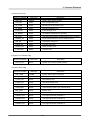
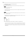
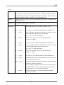
3.1.1. Identifiers
▷
Alphabet and all letters starting with underline (_), and all the mixed letters with numbers and
underlines can be identifiers.
▷
Identifiers are used as variable names.
▷
Blank (space) is not allowed in identifiers.
▷
In case of variables, identifiers are generally 16 letters of the alphabet while input/output variable
and instance, 8 letters of the alphabet.
▷
There’s no difference between small letters and capitals in alphabet; all the letters of the alphabet
are recognized as capitals.
Types
Examples
Capital letters and numbers
IW210, IW215Z, QX75, IDENT
Capital letters, numbers and underline
LIM_SW_2, LIMSW5, ABCD, AB_CD
Capital letters and numbers starting with the
_MAIN, _12V7, _ABCD
underline (_)
3.1.2. Data Expression
The data in GLOFA PLC is: numbers, a string of characters, time letters, etc.
Types
Examples
Integer
-12, 0, 123_456, +986
Real number
-12.0, 0.0, 0.456, 3.14159_26
Real number with an exponent
-1.34E-12, 1.0E+6, 1.234E6
Binary number
2#1111_1111, 2#1110_0000
8#377 (decimal 255)
Octal number
8#340 (decimal 224)
16#FF (decimal 255)
Hexadecimal number
16#E0 (decimal 224)
BOOL data
0, 1, TRUE, FALSE
3-1
3. Common Elements
3.1.2.1. Numbers
▷
There are integer and real numbers.
▷
Discontinuous underline (_) can be placed between numbers and it doesn’t have any meaning.
▷
Decimal complies with general decimal literal expression and if there is a decimal point, this will be
real numbers.
▷
In case of expressing exponent, plus/minus signs can be used. The letter ‘E’ standing for the
exponent does not distinguish capitals from small letters.
▷
When using real numbers with exponents, the followings are not allowed.
Ex) 12E-5 ( ×)
▷
12.0E-5 ( ○)
Integer includes binary, octal, hexadecimal numbers, not to mention decimal, which can be
distinguished by placing # in front of each number.
▷
0 ~ 9 and A ~ F are used (including small letters a ~ f) in expressing hexadecimal.
▷
Not available to have plus/minus signs in expressing hexadecimal.
▷
Boolean data may be expressed as an integer 0 or 1.
3.1.2.2. Character String
▷
Character string covers all the letters surrounded with single inverted commas.
▷
The length is limited up to 16 letters in case of character string constant and for an initialization
case it does within 30 letters.
Ex)
‘CONVEYER’
3.1.2.3. Time Letters
▷
Time letters are classified into these: 1) Duration data which is calculating and controlling the
elapsed time of a controlling event; 2) Time of Day and Date data which is displaying the time of the
starting/ending point of a controlling event.
3.1.2.3.1. Duration
▷
Duration data starts with the reserved word, 'T#' or 't#'.
▷
Several data types such as date (d), hour (h), minute (m), second (s) and millisecond (ms) should
be written in order and duration date can start with any unit among them. Millisecond (ms), the
minimum unit can be omitted but don’t skip the medium unit between duration units.
▷
Not allowed to use the underline (_).
▷
Duration data can overflow at the maximum unit, if any, and the data with a decimal point is
available except ‘ms’. It does not exceed T#49d17h2m47s295ms (32bits by ‘ms’ unit).
▷
The data is limited to the third decimal place in the second unit (s).
▷
Decimal point is not available at ‘ms’ unit.
3-2
3. Common Elements
▷
Capital and small letters are both available.
Content
Examples
T#14ms, T#14.7s, T#14.7m, T#14.7h
Duration (no underline)
t#14.7d, t#25h15m, t#5d14h12m18s356ms
3.1.2.3.2. Time of Day and Date
▷
There are three types expressing ‘Time of Day and Date’ as follows: Date; Time of Day; Date and
Time.
Content
Prefix as a reserved word
Date prefix
D#
Time of Day prefix
TOD#
Date and Time prefix
DT#
▷
The starting point of date is January 1st, 1984.
▷
There's a limit on 'Time of Day’ and ‘Date and Time', which is up to the third decimal place in the
‘ms’ unit.
▷
The overflow is not allowed for all the units when expressing ‘Time of Day’ and ‘Date and Time’.
Content
Examples
D#1984-06-25
Date
d#1984-06-25
TOD#15:36:55.36
Time of Day
tod#15:36:55.369
DT#1984-06-25-15:36:55.36
Date and Time
dt#1984-06-25-15:36:55.369
3-3
3. Common Elements
3.2 . Data Type
Data has a data type to show its character.
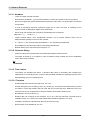
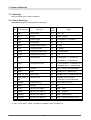
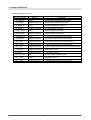
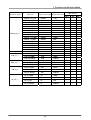
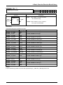
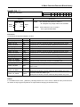
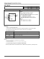
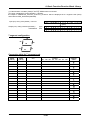
3.2.1. Basic Data Type
GLOFA PLC supports the following basic data types.
No
Reserved Word
Data Type
Size
Range
(bits)
1
SINT
Short Integer
8
-128 ~ 127
2
INT
Integer
16
-32768 ~ 32767
3
DINT
Double Integer
32
-2147483648 ~ 2147483647
4
LINT
Long Integer
64
-2 ~ 2 -1
5
USINT
Unsigned Short Integer
8
0 ~ 255
6
UINT
Unsigned Integer
16
0 ~ 65535
7
UDINT
Unsigned Double Integer
32
0 ~ 4294967295
8
ULINT
Unsigned Long Integer
64
0 ~ 2 -1
9
REAL
Real Numbers
32
-3.402823E38 ~ -1.401298E-45
63
63
64
1.401298E-45 ~ 3.402823E38
10
LREAL
Long Real Numbers
64
-1.7976931E308 ~-4.9406564E-324
4.9406564E-324 ~ 1.7976931E308
11
TIME
Duration
32
T#0S ~ T#49D17H2M47S295MS
12
DATE
Date
16
D#1984-01-01 ~ D#2163-6-6
13
TIME_OF_DAY
Time of Day
32
TOD#00:00:00 ~ TOD#23:59:59.999
14
DATE_AND_TI
Date and Time
64
DT#1984-01-01-00:00:00 ~
ME
DT#2163-12-31-23:59:59.999
15
STRING
Character String
30*8
Limited within 30 letters.
16
BOOL
Boolean
1
0, 1
17
BYTE
Bit String of Length 8
8
16#0 ~ 16#FF
18
WORD
Bit String of Length 16
16
16#0 ~ 16#FFFF
19
DWORD
Bit String of Length 32
32
16#0 ~ 16#FFFFFFFF
20
LWORD
Bit String of Length 64
64
16#0 ~ 16#FFFFFFFFFFFFFFFF
※ LINT, ULINT, REAL, LREAL, LWORD are available in GM1 and GM2 only.
3-4
3. Common Elements
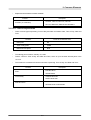
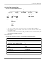
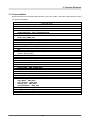
3.2.2. Data Type Hierarchy Chart
Data types used in GLOFA PLC are as follows:
ANY
ANY_NUM
ANY_BIT
ANY STRING
LWORD (GM1,2)
ANY_REAL
ANY_INT
(GM1,2)
LINT (GM1,2) WORD
LREAL
DINT
REAL
INT
ANY_DATE
TIME
ATE_AND_TIME
DWORD
DATE
TIME_OF_DAY
BYTE
BOOL
SINT
ULINT (GM1,2)
UDINT
UINT
USINT
▷
LINT, ULINT, LWORD and ANY_REAL (LREAL, REAL) are available in GM1 and GM2 only.
▷
Data expressed as ANY_NUM includes LREAL, REAL, LINT, DINT, INT, SINT, ULINT, UDINT,
UINT, USINT hereafter.
▷
For example, if a data type is expressed as ANY_BIT in GM3, it can use one of the following data
types: DWORD, WORD, BYTE and BOOL.
3.2.3. Initial Value
If an initial value of data were not assigned, it would be automatically assigned as below.
Data Type
Initial Value
SINT, INT, DINT, LINT
0
USINT, UINT, UDINT, ULINT
0
BOOL, BYTE, WORD, DWORD, LWORD
0
REAL, LREAL
0.0
TIME
T#0s
DATE
D#1984-01-01
TIME_OF_DAY
TOD#00:00:00
DATE_AND_TIME
DT#1984-01-01-00:00:00
STRING
' ' (empty string)
3-5
3. Common Elements
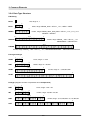
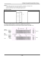
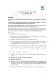
3.2.4. Data Type Structure
# Bit String
BOOL
1 bit, range: 0, 1
7
0
BYTE
8 bits, range: 2#0000_0000 ~ 2#1111_1111, 16#00 ~ 16#FF
15
87
0
WORD
16 bits, range: 2#0000_0000 _0000_0000 ~ 2#1111_1111_1111_1111
16#0000 ~ 16#FFFF
31
16 15
0
DWORD
32 bits, range: 2#0000_...000 ~ 2#1111_...111
16#00000000 ~ 16#FFFFFFFF
63
32 31
0
LWORD
64 bits, range: 2#0000_...000 ~ 2#1111_...111, 16#0000000000000000 ~ 16#FFFFFFFFFFFFFFFF
# Unsigned Integer
7
0
USINT
8 bits, range: 0 ~ 255
15
87
0
UINT
16 bits, range: 0 ~ 65,535
31
16 15
0
UDINT
32 bits, range: 0 ~ 4,294,967,295
63
32 31
0
ULINT
64
64 bits, range: 0 ~ 2 -1
# Integer (Negative number is expressed as 2's Complement.)
7
0
SINT
8 bits, range: -128 ~ 127
15
87
0
INT
16 bits, range: -32,768 ~ 32,767
31
16 15
0
DINT
32 bits, range: -2,147,483,648 ~ 2,147,483,647
63
32 31
LINT
63
63
64 bits, range: -2 ~ 2 -1
3-6
0
3. Common Elements
# Real (based on the IEEE Standard 754-1984)
31 30
23 22
REAL
SExponent
LREAL
S
0
32 bits, range: ±1.401298E-45 ~ ±3.402823E38
Fraction
Exponent
Fraction
63 62
52 51
0
64 bits, range: ±4.9406564E-324 ~ ±1.7976931E308
- S: sign (If it’s 0, the data is a positive number; otherwise, a negative number).
e-127
- Exponent: exponent of 2 (2
: for REAL, e=b30b29...b23; for LREAL, e=b62b61...b52).
- Fraction: a decimal fraction (Fraction: for REAL, f=b22b21...b0; for LREAL, e=b51b52...b0).
# Time
31
0
TIME
32 bits, range: 0 ~ 4,294,967,295ms
T#49d17h2m47s295ms
# Date
63
DT
48 47
32 31
0000000000000000
DATE
TOD
64bits, range: DT#1984-01-01-00:00:00 ~
15
0
DT#2163-12-31-23:59:59.999
0
DATE
16bits, range: D#1984-01-01 ~ D#2163-6-6
31
0
TOD
32bits, range: TOD#00:00:00 ~ TOD#23:59:59.999
#BCD
7
43
1
(BYTE)
0
0
10
10
3
2
15
(WORD)
87
10
10
31
0
1
10
24 23
7
(DWORD)
8bits, range: 0 ~ 99
10
6
10
10
16bits, range: 0 ~ 9999
16 15
5
10
63
(LWORD)
0
4
10
87
3
2
10 10
0
1
0
10
10
9
8
48 47
15
14
10 10
13
10
12
32bits, range: 0 ~ 99,999,999
32 31
11
10 10
10
10 10
10
16 15
7
10
6
10
5
10
4
10
0
3
10
2
10
1
10
0
10
64bits, range: 0 ~ 9,999,999,999,999,999
3-7
3. Common Elements
3.3. Variable
A variable, data used in the program, has its own value. ‘Variable’ means something that can vary such
as an input/output of PLC, memory, etc.
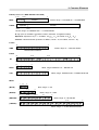
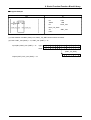
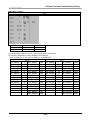
3.3.1. Variable Expression
▷
Variables can be expressed in two ways: one is to give a name to a data element using an identifier
(Variable by Identifier) and the other is to directly assign a memory address or an input/output of
PLC to a data element (Direct Variable).
▷
A variable by identifier should be unique within its ‘effective scope’ (program area where the
variable was declared) in order to distinguish it from other variables.
▷
A direct variable is expressed as one, which starts with the percent sign (%) followed by the
‘location prefix’, a prefix of the data size, and more than one unsigned integer numbers divided by a
period (.). The prefix are shown as below:
Location prefix
No.
Prefix
Meaning
1
Ⅰ
Input Location
2
Q
Output Location
3
M
Memory Location
Size prefix
No.
Prefix
Meaning
1
X
1 bit size
2
None
1 bit size
3
B
1 BYTE (8 bits) size
4
W
1 WORD (16 bits) size
5
D
1 DOUBLE WORD (32 bits) size
6
L
1 LONG WORD (64 bits) size
Expression format
%[Location Prefix][Size Prefix] n1.n2.n3
Ⅰ, Q
No.
n1
M
Base number (starting from “0”)
n1 data according to [size prefix]
(starting from “0”)
n2
Slot number (starting from “0”)
n2 bit of n1 data (starting from “0”):
available to omit
n3
n3 data according to the [size prefix]
(starting from “0”)
3-8
Not used.
3. Common Elements
Examples
th
%QX3.1.4 or %Q3.1.4
4 output of no.1 slot on no.3 base (1bit)
%Ⅰ
Ⅰ W2.4.1
1 word input of no.4 slot on no.2 base (16bits)
%MD48
48 double word memory
%MW40.3
3 bit of 40 word memory
st
th
rd
th
(Internal memory doesn’t have a base or slot number.)
▷
Small letter is not allowed as a prefix.
▷
A variable without a size prefix is treated as 1 bit.
▷
Direct variables are available to use without a variable declaration.
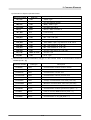
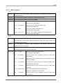
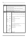
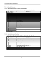
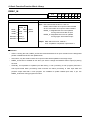
3.3.2. Variable Declaration
▷
Program elements (programs, functions, function blocks, etc) have declaration parts to edit their
variables to use.
▷
Users should declare variables first to use them in the program elements.
▷
The contents of a variable declaration are as follows:
1) Variable types: how to declare variables?
Variable types
Description
VAR
General variable available to read/write
VAR_RETAIN
Retaining (data-keeping) variable
VAR_CONSTANT
Read Only Variable
VAR_EXTERNAL
Declaration to use the variable declared as VAR_GLOBAL
Reference
When declaring Resource Global Variable and Configuration Global Variable, variable formats are
VAR_GLOBAL, VAR_GLOBAL_RETAIN, and VAR_GLOBAL_CONSTANT; VAR_EXTERNAL is not
available for them.
2) Data type: sets a variable data type.
3) Memory allocation: assigns memory for a variable.
Auto: the compiler sets a variable location automatically (Automatic Allocation Variable).
Assign (AT): a user sets a variable location, using a direct variable (Direct Variable).
3-9
3. Common Elements
Reference
The location of Automatic Allocation Variable is not fixed. If variable VAL1, for example, was
declared as BOOL, it is not fixed in the internal memory; the compiler and linker fix its location. If the
program is compiled again after modification, the location may change.
The merit of Automatic Allocation Variable is that users don’t have to care the location of the internal
variables because its location is not overlapped as long as a variable name is different from others.
It is recommended not to use Direct Variable except %Ⅰ
Ⅰ and %Q because the location of a variable
is fixed and it could be overlapped in a wrong-used case.
▷
Initial Value Assignment: assigns an initial value. A variable is set with an initial value as is shown in
‘3.2.3. Initial Value’ if not assigned.
Reference
The initial value is not assigned when it comes to VAR_EXTERNAL.
In case of ‘Variable Declaration’, you cannot assign an initial value to %Ⅰ
Ⅰ or %Q variables.
▷
You can declare variable VAR_RETAIN that keeps its data in case of power failure. Rules are:
1) ‘Retention Variable’ retains its data when the system is set as ‘Warm Restart’.
2) In case of ‘Cold Restart’, variables are initialized as the initial values set by users or the basic initial
values as are shown in ‘3.2.3 Initial Value’.
▷
Variables, which are not declared as VAR_RETAIN, are to be initialized as the initial values set by a
user or the basic initial values in case of Warm or Cold Restart’.
Reference
Variables, which are assigned as %I or %Q, are not to be declared as VAR_RETAIN or
VAR_CONSTANT.
▷
Users can declare variables 'Array' with Elementary Data Type. When declaring the Array Variable,
users are supposed to set Data Type and Array Size; ‘String’ among Elementary Data Type is not
allowed.
▷
Effective scope of variable declaration, the area which is available to use the variable, is limited to
the program where variables are declared. And users can't use variables declared in other program
in the above area. On the contrary, users can get an access to 'Global Variable' from other program
elements by declaring it as 'VAR_EXTERNAL': 'Configuration Global Variable' can be used in all
program elements of all resources; 'Resource Global Variable' can be used in all program elements
of the very resource.
3-10
3. Common Elements
Examples of Variable Declaration
Variable Name
Variable Kind
Data Type
Initial Value
I_VAL
VAR
INT
BIPOLAR
VAR_RETAIN
REAL
Auto
LIMIT_SW
VAR
BOOL
%IX1.0.2
GLO_SW
VAR_EXTERNAL
DWORD
Auto
READ_BUF
VAR
ARRAY OF INT[10]
Auto
3-11
1234
Memory Allocation
Auto
3. Common Elements
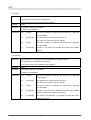
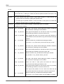
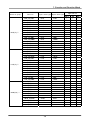
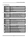
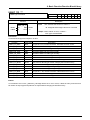
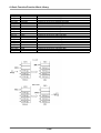
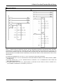
3.3.3. Reserved Variable
▷
‘Reserved Variable’ is the variables previously declared in the system. These variables are used for
special purposes and users cannot declare other variables with the Reserved Variable names.
▷
Users can use these reserved variables without variable declaration.
▷
For further information, please refer to ‘User’s Manual’.
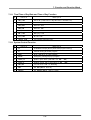
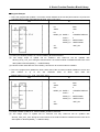
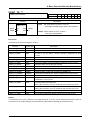
1) User Flag
Reserved Variable
Data Type
Description
_ERR
BOOL
Operation error contact
_LER
BOOL
Operation error latch contact
_T20MS
BOOL
20ms clock contact
_T100MS
BOOL
100ms clock contact
_T200MS
BOOL
200ms clock contact
_T1S
BOOL
1 sec. clock contact
_T2S
BOOL
2 sec. clock contact
_T10S
BOOL
10 sec. clock contact
_T20S
BOOL
20 sec. clock contact
_T60S
BOOL
60 sec. clock contact
_ON
BOOL
All time ON contact
_OFF
BOOL
All time OFF contact
_1ON
BOOL
1 scan ON contact
_1OFF
BOOL
1 scan OFF contact
_STOG
BOOL
Reversal at every scanning
_INIT_DONE
BOOL
Initial program completion
_RTC_DATE
DATE
Current date of RTC
_RTC_TOD
TOD
Current time of RTC
_RTC_WEEK
UINT
Current day of RTC
3-12
3. Common Elements
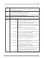
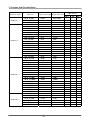
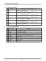
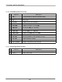
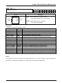
2) System Error Flag
Reserved Variable
Data Type
Description
_CNF_ER
WORD
System error (Heavy trouble)
_CPU_ER
BOOL
CPU configuration error
_IO_TYER
BOOL
Module type inconsistency error
_IO_DEER
BOOL
Module installation error
_FUSE_ER
BOOL
Fuse shortage error
_IO_RWER
BOOL
I/O module read/write error (trouble)
_SP_IFER
BOOL
Special/communication module interface error (trouble)
_ANNUN_ER
BOOL
Heavy trouble detection error of external device
_WD_ER
BOOL
Scan Watch-Dog error
_CODE_ER
BOOL
Program code error
_STACK_ER
BOOL
Stack Overflow error
_P_BCK_ER
BOOL
Program error
3) System Error Release Flag
Reserved Variable
_CNF_ER_M
Data Type
BYTE
Description
System error (heavy trouble) release
4) System Alarm Flag
Reserved variable
Data type
Description
_CNF_WAR
WORD
System Alarm (Alarm message)
_RTC_ERR
BOOL
RTC data error
_D_BCK_ER
BOOL
Data backup error
_H_BCK_ER
BOOL
Hot restart unable error
_AB_SD_ER
BOOL
Abnormal Shutdown
_TASK_ERR
BOOL
Task conflict (normal cycle, external task)
_BAT_ERR
BOOL
Battery error
_ANNUN_WR
BOOL
Light trouble detection of external device
_HSPMT1_ER
BOOL
Over high-speed link parameter 1
_HSPMT2_ER
BOOL
Over high-speed link parameter 2
_HSPMT3_ER
BOOL
Over high-speed link parameter 3
_HSPMT4_ER
BOOL
Over high-speed link parameter 4
3-13
3. Common Elements
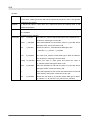
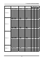
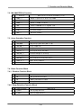
5) Detailed System Error Flag
Reserved variable
Data type
Description
_IO_TYER_N
UINT
Module type inconsistency slot number
_IO_TYERR
ARRAY OF BYTE
Module type inconsistency location
_IO_DEER_N
UINT
Module installation slot number
_IO_DEERR
ARRAY OF BYTE
Module installation location
_FUSE_ER_N
UINT
Fuse shortage slot number
_FUSE_ERR
ARRAY OF BYTE
Fuse shortage slot location
_IO_RWER_N
UINT
I/O module read/write error slot number
_IO_RWERR
ARRAY OF BYTE
I/O module read/write error slot location
_ANC_ERR
ARRAY OF UINT
Heavy trouble detection of external device
_ANC_WAR
ARRAY OF UINT
Light trouble detection of external device
_ANC_WB
ARRAY OF BOOL
Alarm message detection bit map of external device
_TC_BMAP
ARRAY OF BOOL
Task conflict mark
_TC_CNT
ARRAY OF UINT
Task conflict counter
_BAT_ER_TM
DT
Battery voltage drop-down time
_AC_F_CNT
UINT
Shutdown counter
_AC_F_TM
ARRAY OF DT
Instantaneous service interruption history
3-14
3. Common Elements
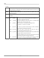
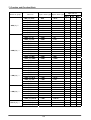
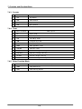
6) Information of System Operation Status
Reserved variable
Description
Data type
_CPU_TYPE
UINT
System Type
_VER_NUM
UINT
PLC O/S Version number
_MEM_TYPE
UINT
Memory module type
_SYS_STATE
WORD
PLC mode and status
_RST_TY
BYTE
Restart mode information
_INIT_RUN
BIT
Initializing
_SCAN_MAX
UINT
Max. scan time (ms)
_SCAN_MIN
UINT
Min. scan time (ms)
_SCAN_CUR
UINT
Current scan time (ms)
_STSK_NUM
UINT
Task number requiring execution time check
_STSK_MAX
UINT
Max. task execution time (ms)
_STSK_MIN
UINT
Min. task execution time (ms)
_STSK_CUR
UINT
Current task execution time (ms)
_RTC_TIME
ARRAY OF BYTE
Current time
_SYS_ERR
UINT
Error type
7) Communication Module Information Flag [n is a slot number where a communication module is
installed (n = 0 ~ 7)]
Reserved variable
Data type
Description
_CnVERNO
UINT
Communication module version number
_CnTXECNT
UINT
Communication transmit error
_CnRXECNT
UINT
Communication receive error
_CnSVCFCNT
UINT
Communication service process error
_CnSCANMX
UINT
Max. communication scan time (1ms unit)
_CnSCANAV
UINT
Average communication scan time (1ms unit)
_CnSCANMN
UINT
Minimum communication scan time (1ms unit)
_CnLINF
UINT
Communication module system information
_CnCRDER
BOOL
Communication module system error (Error = 1)
_CnSVBSY
BOOL
Lack of common RAM resource (Lack = 1)
_CnIFERR
BOOL
Interface error (error = 1)
_CnINRING
BOOL
Communication in ring (IN_RING = 1)
3-15
3. Common Elements
8) Remote I/O Control Flag [m is a slot number where a communication module is installed (m = 0 ~ 7)]
Reserved variable
_FSMm_RESET
Data type
Description
Remote Ⅰ/O station reset control (reset = 1)
BOOL (able to write)
_FSMm_IO_RESET BOOL(able to write)
Output reset control of remote I/O station (reset = 1)
_FSMm_st_no
Station number of corresponding remote I/O station
USINT (able to write)
9) Detailed High-speed Link Information Flag [m is a high-speed link parameter number (m = 1, 2, 3, 4)]
Reserved variable
Data type
Description
_HSmRLINK
BOOL
HS RUN_LINK information
_HSmLTRBL
BOOL
_HSmSTATE
ARRAY OF BOOL
_HSmMOD
ARRAY OF BOOL
_HSmTRX
ARRAY OF BOOL
_HSmERR
ARRAY OF BOOL
Abnormal information of HS (Link Trouble)
General communication status information of k data
block
Station mode information of k data block at HS link
parameter (Run = 1, Other = 0)
Communication status information of k data block at HS
link parameter (Normal = 1, Abnormal = 0)
Station status information of k data block at HS link
parameter (Normal = 0, Error = 1)
3-16
3. Common Elements
3.4. Reserved Word
Reserved words are previously defined words to use in the system. And these reserved words cannot
be used as an identifier.
Reserved words
ACTION ... END_ACTION
ARRAY ... OF
AT
CASE ... OF ... ELSE ... END_CASE
CONFIGURATION ... END_CONFIGURATION
Name of data type
DATE#, D#
DATE_AND_TIME#, DT#
EXIT
FOR ... TO ... BY ... DO ... END_FOR
FUNCTION ... END_FUNCTION
FUNCTION_BLOCK ... END_FUNCTION_BLOCK
Name of function block
IF ... THEN ... ELSIF ... ELSE ... END_IF
OK
Operator (IL language)
Operator (ST language)
PROGRAM
PROGRAM ... END_PROGRAM
REPEAT ... UNTIL ... END_REPEAT
RESOURCE ... END_RESOURCE
RETAIN
RETURN
STEP ... END_STEP
STRUCTURE ... END_STRUCTURE
T#
TASK ... WITH
TIME_OF_DAY#, TOD#
TRANSITION ... FROM... TO ... END_TRANSITION
TYPE ... END_TYPE
VAR ... END_VAR
VAR_INPUT ... END_VAR
VAR_OUTPUT ... END_VAR
VAR_IN_OUT ... END_VAR
VAR_EXTERNAL ... END_VAR
VAR_ACCESS ... END_VAR
VAR_GLOBAL ... END_VAR
WHILE ... DO ... END_WHILE
WITH
3-17
3. Common Elements
3.5. Program Type
▷
There are three types of program: function, function block and program.
▷
It is not available to call its own program in the program (reflexive call is prohibited).
3.5.1. Function
▷
A function has one output.
Example
If there is function A that is to add input IN1 and IN2 and then add 100 to the sum of IN1 and IN2. and
the output 1 <= IN1 + IN2 + 100, this function will be correct. However, if the above function has one
more output (output 2 <= IN1 + IN2 * 100), this will not be a function because it has 2 outputs: output 1
and output 2.
▷
A function does not have data to preserve its state inside. This means if an input is constant, an
output value should be constant, which is a function.
Example
If there is function B whose contents are
Output 1 <= IN1 + IN2 + Val
Val <= output1 (where, Val is an internal variable),
This cannot be a function as there is internal variable Val. To have an internal variable means that an
output will be different even if there is a same input. Output 1 value is subject to change because of
Val variable even if the value of IN1 and IN2 are constant as is shown on the above. Compared with
the above function A, function A will have output 1 value (150) when IN1 is 20 and IN2 is 30. This
shows that the output value will be constant if inputs are constant.
▷
An internal variable of a function is not available to have an initial value.
▷
Users can’t declare a function as VAR_EXTERNAL and use it.
▷
It is not available to use direct variables inside the function.
▷
A function will be called by program elements and used.
▷
Data transfer from program composition elements, which call the function, to the function will be
executed through an input of a function.
3-18
3. Common Elements
Example
SHL function is a basic function that shifts input IN to the left as many as N bit number and produces
it as an output. Program composition elements call SHL function, assigning a value of TEST variable
to input IN and a value of NO variable to input N. The result will be stored in OUTPUT variable.
▷
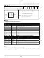
A function is inserted into a library for use.
▷
It is not available to call a function block or a program inside the function.
▷
A function has a variable whose name is the same as that of the function and whose data type is
the same as the data type of the result of the function. This variable is automatically created when
making a function, and the result value of the function will be written in the output.
Example
If a function name is WEIGH and a data type of a result value is WORD, a variable whose name is
WEIGH and whose data type is WORD will be automatically created inside the function. Users can
store the result of function in variable WEIGH.
ST
WEIGH
(example in IL)
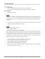
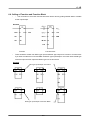
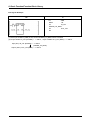
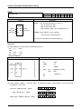
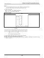
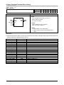
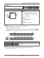
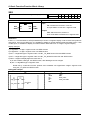
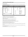
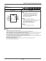
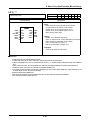
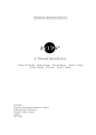
3.5.2 Function Block
▷
A function block has several outputs.
▷
A function block has data inside. A function block should declare the instance as it declares
variables before using them. Instance is a set of variables used in a function block. A function block
should have its data memory to preserve the output value as well as variables used inside, which is
called as “instance.” A program is a kind of a function block and also needs to declare “instance.”
However, users cannot call a program inside a program or a function block for use, contrary to a
function block.
▷
In order to use the output value of a function block, it is required to place a period (.) between the
name of instance and the output name.
3-19
3. Common Elements
Example
Instance name
T1
TON
IN
Q
PT
ET
Output
Input
General examples of a function block are Timer and Counter. On-delay timer function block is TON
and this is executed if IN is ON after users declare T1 as “instance.” In order to use timer output
contact and duration value, it is required to place a period (.) between the name of instance and the
output name. In case of a timer function block, the output contact and the elapsed time value for the
instance are T1.Q and T1.ET respectively because the output contact name is Q and the elapsed
time contact name is ET. The output value of a function is a return value by calling a function while
the output value of a function block is fixed for the instance.
▷
Users cannot declare a direct variable inside a function block. However, users can use a direct
variable declared as Global Variable and allocated according to ‘Assign (AT)’ after declaring it as
VAR_EXTERNAL.
▷
A function block is inserted into a library for use.
▷
It is not available to call a program inside the function block.
3.5.3 Program
▷
Users can use a program after declaring an instance like a function block.
▷
It is available to use direct variables in the program.
▷
A program does not have input/output variables.
The calling of a program is defined in the resource.
3-20
4. SFC
4. SFC (Sequential Function Chart)
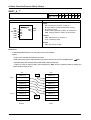
4.1. Overview
▷
SFC is a structured language that extends an application program in the form of flow chart
according to the processing sequence, using a PLC language.
▷
SFC splits an application program into step and transition, and provides how to connect them each
other. Each step is related to action and each transition is related to transition condition.
▷
As SFC should contain the state information, only program and function block among program
types are available to apply this SFC.
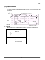
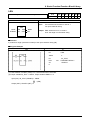
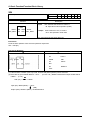
▷
Type
Initial step
Action name
Action
Step
Selection
branch
Transition
Jump
Transition name
Parallel
branch
Label
Qualifier
4.2. SFC Structure
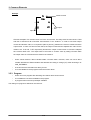
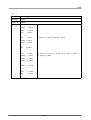
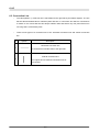
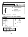
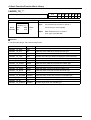
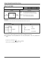
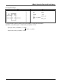
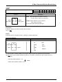
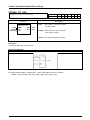
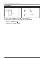
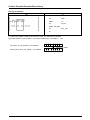
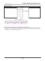
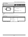
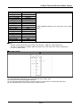
4.2.1. Step
▷
Step indicates a sequence control unit by connecting the action.
▷
When step is in an active state, the attached content of action will be executed.
▷
The initial step is one to be activated first.
Initial step
Transition condition
Step
▷
If a next transition condition of activated initial step (S1) is established, step 1 (S1) that is currently
activated becomes deactivated and Step 2 (S2) connected to S1 becomes activated.
4-1
4. SFC
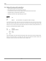
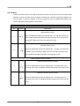
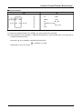
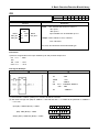
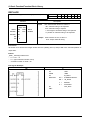
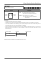
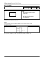
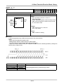
4.2.2. Transition
▷
Transition indicates the execution condition between steps.
▷
A transition condition should be described as a PLC language such as IL or LD.
The result of a transition condition should always be a BOOL type and the variable name should be
TRANS for any transition.
▷
In case that the result of transition condition is 1, the current step is deactivated and the next step is
activated.
▷
There must be a transition between step and step.
TRAN1
The content of TRAN1
When TRANS is on, S1 will be deactivated and S2 activated.
TRANS is the internally declared variable.
A transition condition of all transition should be output in TRANS variable.
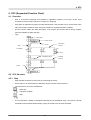
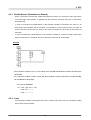
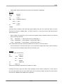
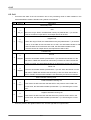
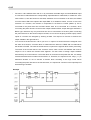
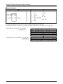
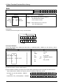
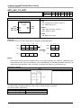
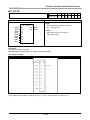
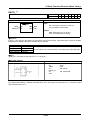
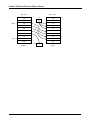
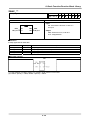
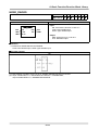
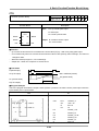
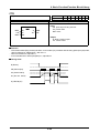
4.2.3. Action
▷
Each step is able to connect up to two actions.
▷
The step without action is regarded as a waiting action and it is required to wait until the next
transition condition will be 1.
▷
Action is composed of PLC language such as IL or LD and the content of action will be executed
while the step is activated.
▷
Action qualifier will be used to control action.
▷
When action becomes deactivated state after activating, the contact output in action will be 0.
However, S, R, function and function block output retain their state before they become nonactivating.
4-2
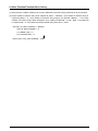
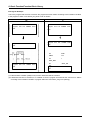
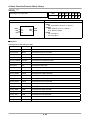
4. SFC
The content of ACTION1
The content of ACTION2
- ACTION1 will be executed only when S1 is activated.
- ACTION2 will be executed until S1 meets R qualifier after activated.
It goes on executing even if S1 is deactivated.
- When action is deactivated, this action is Post Scanned and then passes to the next step.
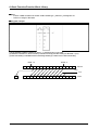
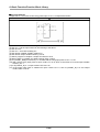
Reference
Post Scan
When action is deactivated, this action is scanned again.
As it is scanned as if there were a contact (contact with the value of 0) in the beginning part of an action
program, the program output, which is composed of contacts, will be 0.
Function, function block, S, R output etc., are not included.
In this figure, as the contact of postscan is 0, C and %Q0.0.0 will be 0.
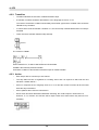
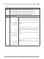
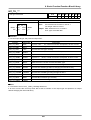
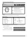
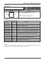
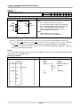
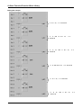
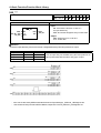
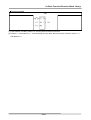
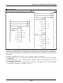
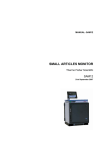
4.2.4. Action Qualifier
▷
Whenever action is used, action qualifier will be followed.
▷
The action of step defines an executing point and time according to the assigned qualifier.
▷
Types of action qualifier are as follows:
4-3
4. SFC
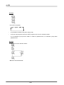
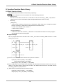
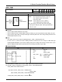
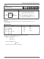
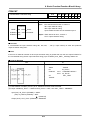
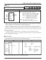
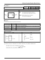
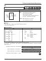
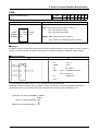
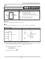
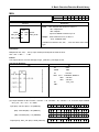
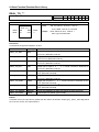
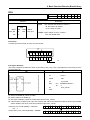
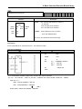
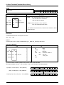
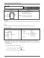
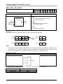
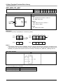
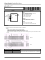
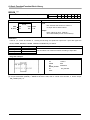
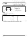
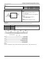
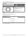
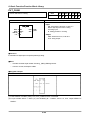
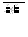
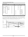
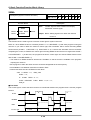
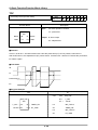
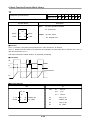
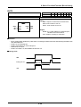
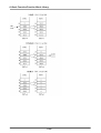
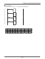
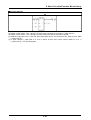
1) N (Non-Stored)
Action is executed only when the step is activated.
Active state
Step connected
by N
Action
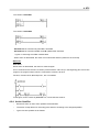
2) S (Set)
It continues the action after the step is deactivated (until the action is reset by R qualifier).
Step connected
by S
Action
Step connected
by R
Step connected
by S
Action
Step connected
by R
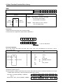
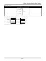
3) R (Overriding Reset)
It terminates the execution of an action previously started with the S, SD, SL or DS qualifier.
4-4
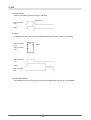
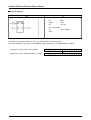
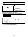
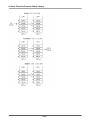
4. SFC
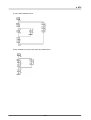
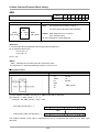
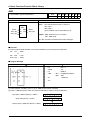
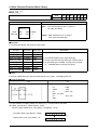
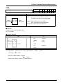
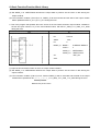
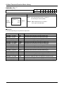
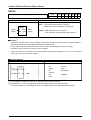
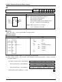
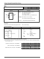
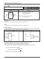
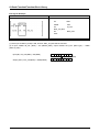
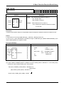
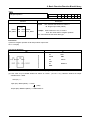
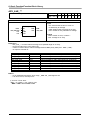
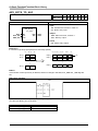
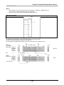
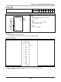
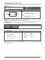
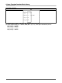
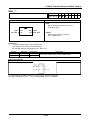
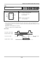
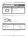
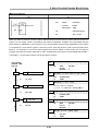
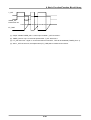
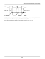
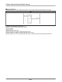
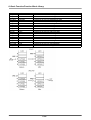
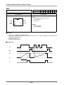
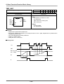
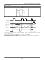
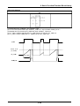
4) L (Time Limited)
It start the action when the step becomes active and continue until the step goes inactive or a set
time elapses.
Step connected
by L
Action
Step connected
by L
Action
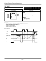
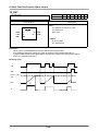
5) D (Time Delayed)
Start a delay timer when the step becomes active - after the time delay the action starts (if step still
active) and continues until deactivated.
Step connected
by D
Action
Step connected
by D
Action
4-5
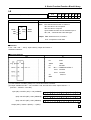
4. SFC
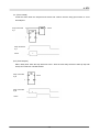
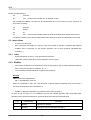
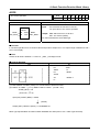
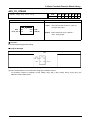
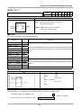
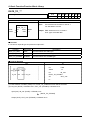
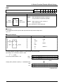
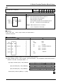
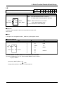
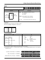
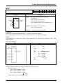
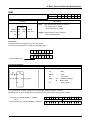
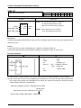
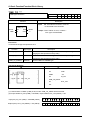
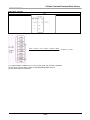
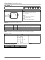
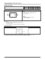
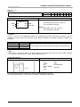
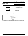
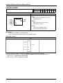
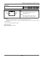
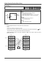
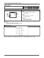
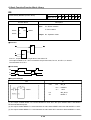
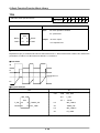
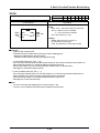
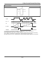
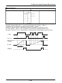
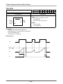
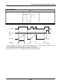
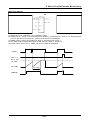
6) P (Pulse)
It starts the action when the step becomes active and executes the action only once.
Step connected
by P
Action
Step connected
by P
1 scan
Action
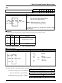
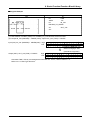
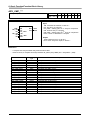
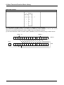
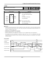
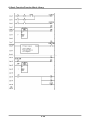
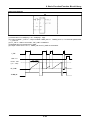
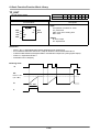
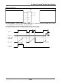
7) SD (Stored & Time Delayed)
It starts a delay timer when the step becomes active - after the time delay, the action starts and
continues until reset (regardless of step activation/deactivation).
Step connected
by SD
Action
Step connected
by R
Step connected
by SD
Action
Step connected
by R
4-6
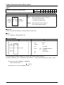
4. SFC
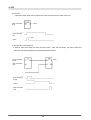
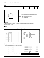
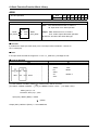
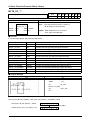
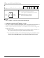
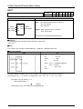
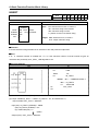
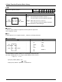
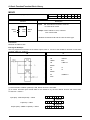
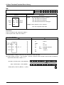
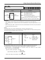
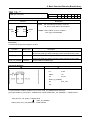
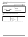
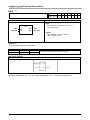
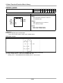
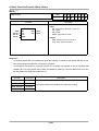
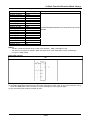
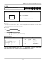
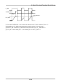
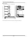
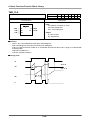
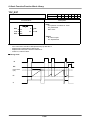
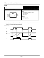
8) DS (Delayed & Stored)
It starts a delay timer when the step becomes active - after the time delay the action starts (if step
still active) and continues until reset by R qualifier.
Step connected
by DS
Action
Step connected
by R
Step connected
by DS
Action
Step connected
by R
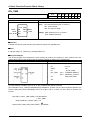
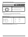
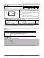
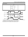
9) SL (Stored & Timed Limited)
It starts the action when the step becomes active and continues for a set time or until the action is
reset (regardless of step activation/deactivation).
Step connected
by SL
Action
Step connected
by R
Step connected
by SL
Action
Step connected
by R
4-7
4. SFC
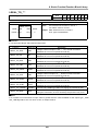
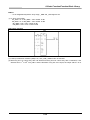
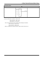
4.3. Extension Regulation
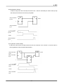
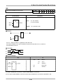
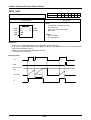
4.3.1. Serial Connection
▷
2 steps are always divided by transitions without connecting directly.
▷
Step always divides 2 transitions without connecting directly.
[correct example]
▷
[wrong example]
For the transition between steps connected by serial, the lower step will be activated if the upper
step is active and the transition condition connected to the next is 1.
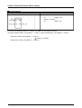
4.3.2. Selection Branch
▷
When a processor executes a selection branch, the processor finds the first path with a true
transition in the order of the program scan and executes the steps and transitions in that path. If
more than one path in a selection branch goes true at the same time, the processor chooses the
left-most path. The following example shows a typical scan sequence.
Example
* In case that the transition condition of T1 is 1,
the order of activation will be S1 -> S2 -> S3.
* In case that the transition condition of T4 is 1,
the order of activation will be S1 -> S4 -> S3.
* In case that the transition condition of T5 is 1,
the order of activation will be S1 -> S5 -> S3.
If the transition conditions are 1 at the same time, the processor chooses the left-most path.
* In case that the transition condition of T1 and T4 is 1 at the same time,
the order of activation will be S1 -> S2 -> S3.
* In case that the transition condition of T4 and T5 is 1 at the same time,
the order of activation will be S1 -> S4 -> S3.
4-8
4. SFC
4.3.3. Parallel Branch (Simultaneous Branch)
▷
When a processor executes the parallel (simultaneous) branch, the processor scans the branch
from left-to-right, top-to-bottom. It appears that the processor executes each path in the branch
simultaneously.
▷
In case of connecting by parallel branch, if the transition condition connected to the next is 1, all
steps tied to this transition will be activated. The extension of each branch will be the same as
serial connection. At this time, the steps in the state of activation are as many as the number of
branches.
▷
In case of combining in parallel branch, if the transition condition is 1 when the state of all the last
steps of each branch is activated, the step connected to the next will be activated.
Example
- If the transition condition of T1 is 1 when S1 is active, S2, S6 and S8 will be activated and S1 will be
deactivated.
- If the transition condition of T4 is 1 when S4, S7 and S8 are activated, S5 will be activated and S4,
S7 and S8 will be deactivated.
* The order of activation
S1-+->S2-->S3-->S4--+->S5
+->S6-->S7---------+
+->S8----------------+
4.3.4. Jump
▷
If the transition condition connected to the next is 1 after the last step of SFC is activated, the initial
step of SFC will be activated.
4-9
4. SFC
Example
* The order of activation
S1
S2
S3
▷
It is possible to extend to the place using a jump.
▷
Jump can only be place at the end of SFC program or the end of a selection branch.
It is not allowed to jump into the inside or outside of parallel branch; it is allowed to jump within
parallel branch.
Example
1) Jump at the end of selection branch
- S2 will be activated after S5.
4-10
4. SFC
2) Jump within parallel branch
3) Not available to jump into the inside of parallel branch..
4-11
4. SFC
MEMO
4-12
5. IL
5. IL (Instruction List)
5.1. Overview
▷
IL is a low-level 'assembler like' language.
▷
IL is applicable to simple PLC systems.
▷
Type
Label
45
46
THERE:
LDN
START
(* Switch input reading *)
Operand
Line No.
Operator
Identifier
Comment
5.2. Current Result: CR
▷
In IL, there is a register that stores an operation result by that time, which is called “CR (current
result)”.
▷
Only one CR exists in IL.
▷
CR is able to be any data type.
▷
The operator that puts a certain value to CR and determines its data type is LD (Load).
Example
LD %IX0.0.0 is to put the value of %IX0.0.0 to the CR. Now, the data type of CR is BOOL because the
data type expressed as X is BOOL. If variable VAL is declared as INT and is written as LD VAL, it
writes the value of VAL to CR and the data type of CR is INT.
▷
ST operator stores the current result (CR) in a variable.
Example
If variable VAL is declared as INT and is written as ST VAL, this means that CR is stored in variable
VAL. At this time, the data type of CR should be INT. Unless CR is an INT type, an error occurs when
compiling.
5-1
5. IL
Please read the following:
LD
%IX0.0.0
ST
VAL
(assume that variable VAL is declared as INT)
CR is assigned as BOOL in the first row and declared as INT in the second row, which results in an
error when compiling.
LD
%IX0.0.0
ST
START
LD
20
ST
VAL
(assume that variable START is declared as BOOL and variable VAL as INT)
The above example is executed normally because the data type to store CR respectively is the same.
5.3. Instructions
▷
IL is a list of instructions.
▷
Each instruction must begin on a new line, and must contain an operator, completed with optional
modifiers and, if necessary, for the specific operation, one or more operands, separated with
commas (',').
5.3.1. Label
▷
A label followed by a colon (':') may precede the instruction.
▷
Labels are used as operands for some operations such as jumps.
5.3.2. Modifier
▷
The modifier character must complete the name of the operator, with no blank characters between
them. There’re three types of modifiers: N, (, C.
▷
The N modifier indicates a Boolean negation of the operand.
Example
ANDN %IX2.0.0 is interpreted as:
CR <= CR AND NOT %IX2.0.0
When N is attached to JMP, CAL and RET with no blank character between them, this means it
executes the instruction when CR is BOOL 0.
▷
Modifier ‘(‘ delays the operation of an operator until it meets operator ‘)’.
As there is only one CR in IL, it is available to execute the delayed operation: CR is kept while other
operations are executed and after that, operation will be done with the stored CR value.
Type
Characteristic
Semantics
(
Modifier
Operation is delayed.
)
Operator
Evaluation deferred operation used with ‘(‘
5-2
5. IL
Example
AND(
%IX1.0.0
OR
%IX2.0.0 )
CR <= CR AND (%IX1.0.0 OR %IX2.0.0)
This means that the execution of AND will be delayed until ‘)’ appears. After the operation inside the
parentheses, %IX1.0.0 OR %IX2.0.0, is executed, the operation with the result will be done.
▷
Modifier ‘C’ indicates that the attached instruction must be executed only if the current result has
the Boolean value 1 (TRUE).
Example
JMPC
THERE
If CR is BOOL 1, jump to THERE.
5.3.3. Basic Operator
▷
Basic operators are as follows:
No.
Operator Modifier
Operand
Semantics
1
LD
N
Data
Set current results equal to operand
2
ST
N
Data
Store current results to operand
3
S
BOOL
If CR is BOOL 1, set Boolean Operand to 1
R
BOOL
If CR is BOOL 1, set Boolean Operand to 0
4
AND
N,(
Data
Boolean AND operation
5
OR
N,(
Data
Boolean OR operation
6
XOR
N,(
Data
Boolean XOR operation
7
ADD
(
Data
Addition operation
8
SUB
(
Data
Subtraction operation
9
MUL
(
Data
Multiplication operation
10
DIV
(
Data
Division operation
11
GT
(
Data
Comparison operation: > (greater than)
12
GE
(
Data
Comparison operation: >= (greater than or equal to)
13
EQ
(
Data
Comparison operation: = (equal to)
14
NE
(
Data
Comparison operation: <> (not equal)
15
LE
(
Data
Comparison operation: <= (less than or equal to)
16
LT
(
Data
Comparison operation: < (less than)
17
JMP
C, N
Label
Jump to label
18
CAL
C, N
Name
Call a function or function block
19
RET
C, N
20
)
Return from a function or function block
Evaluation deferred operation used with ‘(‘
5-3
5. IL
▷
Operators from no. 4 to 16 execute the following functions:
CR <== CR Operation Operand
After executing the operation made between CR and operand value is done, it stores the result in CR.
Example
AND %IX1.0.0 is interpreted as follows:
CR <= CR AND %IX1.0.0
▷
Comparison operator stores its Boolean result in CR after a comparison operation made between
CR and the right operand.
Example
For GT %MW10, if CR is greater than the value of internal memory word 10, the value of CR will be
BOOL 1. Otherwise it will be 0.
▷
The data type of CR is not modified by most of the operation instructions. However, in case of
comparison operators, a data type of CR is changed.
Example
(a)
LD
VAL
EQ
GROSS
(b)
AND
%IX0.0.0
(c)
ST
START
(d)
(assume that variable START is declared as BOOL, and variable VAL and GROSS as INT)
At (a) row, the INT value of VAL is put in CR. At (b) row, after comparing the CR to INT value of
GROSS, if the value is same, it puts BOOL 1 in CR; if not, CR is BOOL 0. At this time, a data type
of CR changes from INT to BOOL. Accordingly, instructions of (c) and (d) rows are normal without
making an error.
5-4
5. IL
5.3.3.1. Basic Operator
(1) LD
Meaning
It loads a value in the current result. A data type of CR changes according to the
operand data type.
Modifier
N: If the operand is BOOL, it negates its value and loads it in CR.
Operand
All the data types including constant are available.
Examples
LD
TRUE
The value of BOOL 1 is loaded in CR.
The data type of CR is BOOL.
LD
INT_VALUE
The value of INT_VALUE is loaded in CR.
The data type of CR is INT.
LD
T#1S
T#1S, time constant, is loaded in CR.
The data type of CR is TIME.
LDN
B_VALUE
The value of B_VALUE is negated and is loaded in CR.
The data type of CR is BOOL.
(2) ST
Meaning
It stores the current result (CR) in a variable (operand).
The data type of both CR and operand should be the same. The current result is not
modified by this operation.
Modifier
N: If CR is BOOL, it negates its value and stores it in the operand. At this time, the
value of CR does not change.
Operand
All the data types except constant are available.
Its data type should be the same as that of CR.
Examples
LD
FALSE
The value of BOOL 0 is loaded in CR.
The data type of CR is BOOL.
ST
B_VALUE1
Stores the value of CR in variable B_VALUE1 of which data
type is BOOL.
STN
B_VALUE2
Negates the value of CR and stores it in B_VALUE2 of which
data type is BOOL.
LD
INT_VALUE
The value of INT_VALUE that is INT variable is loaded in CR.
The data type of CR is INT.
ST
I_VALUE1
Stores the value of CR in variable I_VALUE1 of which data
type is INT.
LD
D#1995-12-25
Date constant D#1995-12-25 is loaded in CR.
At this time, a data type of CR is DATE.
ST
D_VALUE1
Stores the value of CR in variable D_VALUE1 of which data
type is DATE.
5-5
5. IL
(3) S (Set)
Meaning
If CR is BOOL 1, the operand value of which data type is BOOL will be 1.
No operation is processed if CR is BOOL 0.
The current result is not modified by this operation.
Modifier
None
Operand
Only BOOL data type is available.
Constant is not available.
Examples
LD
FALSE
The value of BOOL 0 is loaded in CR. At this time, a data type
of CR is BOOL.
S
B_VALUE1
No operation is processed because CR is 0.
The value of B_VALUE1 does not change.
LD
TRUE
The value of BOOL 1 is loaded in CR. At this time, a data type
of CR is BOOL.
S
B_VALUE2
As CR is 1, the value of B_VALUE2 whose data type is BOOL
will be 1.
(4) R (Reset)
Meaning
If CR is BOOL 1, the operand value whose data type is BOOL will be 0.
No operation is processed if CR is BOOL 0.
The current result is not modified by this operation.
Modifier
None
Operand
Only BOOL data type is available.
Constant is not available.
Examples
LD
FALSE
The value of BOOL 0 is loaded in CR. At this time, a data type
of CR is BOOL.
R
B_VALUE1
No operation is processed because CR is 0.
The value of B_VALUE1 does not change.
LD
TRUE
The value of BOOL 1 is loaded in CR. At this time, a data type
of CR is BOOL.
R
B_VALUE2
As CR is 1, the value of B_VALUE2 whose data type is BOOL
will be 0. The value of CR does not change.
ST
B_VALUE3
The value of CR (Boolean 1) is stored in B_VALUE3 whose
data type is BOOL.
5-6
5. IL
(5) AND
Meaning
After logical AND operation for CR and the operand value, stores the operation result in
CR. At this time, a data type of both CR and the operand should be the same. The
operand value does not change.
Modifier
N: If the operand data type is BOOL, logical AND operation is made between the
operand value and CR after negating the operand value.
(: If a data type of operand is BOOL, moves CR value in other place for a while and
stores the operand value in CR (deferred operation).
Operand
Only BOOL, BYTE, WORD, DWORD, LWORD data types are available.
Constant is also available.
Examples
LD
B_VALUE1
The value of B_VALUE1 whose data type is BOOL is loaded in
CR. At this time, a data type of CR is BOOL.
AND
B_VALUE2
After logical AND operation for CR and the value of B_VALUE2
whose data type is BOOL, stores the result in CR.
ANDN B_VALUE3
After negating the value of B_VALUE3, logical AND operation is
made between CR and the value of B_VALUE3 whose data type
is BOOL.
ST
B_VALUE4
Stores CR value in B_VALUE4 whose data type is BOOL.
B_VALUE4 <== B_VALUE1 AND B_VALUE2 AND NOT (B_VALUE3)
LD
W_VALUE1
The value of W_VALUE1 whose data type is WORD is loaded in
CR. At this time, a data type of CR is WORD.
AND
W_VALUE2
After logical AND operation for CR and the value of W_VALUE2
whose data type is WORD, stores the result in CR.
ST
W_VALUE3
Stores CR value in W_VALUE3 whose data type is WORD.
W_VALUE3 <== W_VALUE1 AND W_VALUE2
LD
B_VALUE1
The value of B_VALUE1 whose data type is BOOL is loaded in
CR. At this time, a data type of CR is BOOL.
AND(
B_VALUE2
Moves CR value in other place and stores the value of
B_VALUE2 whose data type is BOOL in CR.
OR
B_VALUE3
After logical OR operation for CR and the value of B_VALUE3
whose data type is BOOL, stores the result in CR.
)
After logical AND operation for the current CR value and the
moved CR value stored in other place, stores the result in CR.
ST
B_VALUE4
Stores CR value in B_VALUE4 whose data type is BOOL.
B_VALUE4 <== B_VALUE1 AND (B_VALUE2 OR B_VALUE3)
5-7
5. IL
(6) OR
Meaning
After logical OR operation for CR and the operand value, stores the operation result in
CR. At this time, a data type of both CR and the operand should be the same. The
operand value does not change.
Modifier
N: If the operand data type is BOOL, logical AND operation is made between the
operand value and CR after negating the operand value.
(: If a data type of operand is BOOL, moves CR value in other place for a while and
stores the operand value in CR (deferred operation).
Operand
Only BOOL, BYTE, WORD, DWORD, LWORD data types are available.
Constant is also available.
Examples
LD
B_VALUE1
The value of B_VALUE1 whose data type is BOOL is loaded in
CR. At this time, a data type of CR is BOOL.
OR
B_VALUE2
After logical OR operation for CR and the value of B_VALUE2
whose data type is BOOL, stores the result in CR.
ORN
B_VALUE3
After negating the value of B_VALUE3, logical OR operation is
made between CR and the value of B_VALUE3 whose data type
is BOOL.
ST
B_VALUE4
Stores CR value in B_VALUE4 whose data type is BOOL.
B_VALUE4 <== B_VALUE1 OR B_VALUE2 OR NOT (B_VALUE3)
LD
W_VALUE1
The value of W_VALUE1 whose data type is WORD is loaded in
CR. At this time, a data type of CR is WORD.
OR
W_VALUE2
After logical AND operation for CR and the value of W_VALUE2
whose data type is WORD, stores the result in CR.
ST
W_VALUE3
Stores CR value in W_VALUE3 whose data type is WORD.
W_VALUE3 <== W_VALUE1 OR W_VALUE2
LD
B_VALUE1
The value of B_VALUE1 whose data type is BOOL is loaded in
CR. At this time, a data type of CR is BOOL.
OR(
B_VALUE2
Moves CR value in other place and stores the value of
B_VALUE2 whose data type is BOOL in CR.
AND
B_VALUE3
After logical AND operation for CR and the value of B_VALUE3
whose data type is BOOL, stores the result in CR.
After logical OR operation for the current CR value and the
)
moved CR value stored in other place, stores the result in CR.
ST
B_VALUE4
Stores CR value in B_VALUE4 whose data type is BOOL.
B_VALUE4 <== B_VALUE1 OR (B_VALUE2 AND B_VALUE3)
5-8
5. IL
(7) XOR
Meaning
After logical XOR operation for CR and the operand value, stores the operation result in
CR. At this time, a data type of both CR and the operand should be the same. The
operand value does not change.
Modifier
N: If the operand data type is BOOL, logical AND operation is made between the
operand value and CR after negating the operand value.
(: If a data type of operand is BOOL, moves CR value in other place for a while and
stores the operand value in CR (deferred operation).
Operand
Only BOOL, BYTE, WORD, DWORD, LWORD data types are available.
Constant is also available.
Examples
LD
B_VALUE1
The value of B_VALUE1 whose data type is BOOL is loaded in
CR. At this time, a data type of CR is BOOL.
XOR
B_VALUE2
After logical XOR operation for CR and the value of B_VALUE2
whose data type is BOOL, stores the result in CR.
XORN
B_VALUE3 After negating the value of B_VALUE3, logical XOR operation is
made between CR and the value of B_VALUE3 whose data type
is BOOL.
ST
B_VALUE4
Stores CR value in B_VALUE4 whose data type is BOOL.
B_VALUE4 <== B_VALUE1 XOR B_VALUE2 XOR NOT (B_VALUE3)
LD
W_VALUE1
The value of W_VALUE1 whose data type is WORD is loaded in
CR. At this time, a data type of CR is WORD.
XOR
W_VALUE2
After logical XOR operation for CR and the value of W_VALUE2
whose data type is WORD, stores the result in CR.
ST
W_VALUE3
Stores CR value in W_VALUE3 whose data type is WORD.
W_VALUE3 <== W_VALUE1 XOR W_VALUE2
LD
B_VALUE1
The value of B_VALUE1 whose data type is BOOL is loaded in
CR. At this time, a data type of CR is BOOL.
XOR(
B_VALUE2
Moves CR value in other place and stores the value of
B_VALUE2 whose data type is BOOL in CR.
AND
B_VALUE3
After logical AND operation for CR and the value of B_VALUE3
whose data type is BOOL, stores the result in CR.
After logical XOR operation for the current CR value and the
)
moved CR value stored in other place, stores the result in CR.
ST
B_VALUE4
Stores CR value in B_VALUE4 whose data type is BOOL.
B_VALUE4 <== B_VALUE1 XOR (B_VALUE2 AND B_VALUE3)
5-9
5. IL
(8) ADD
Meaning
After addition operation for CR and the operand value, stores the operation result in CR.
At this time, a data type of both CR and the operand should be the same. The operand
value does not change.
Modifier
(: Moves CR value in other place for a while and stores the operand value in CR
(deferred operation).
Operand
Only SINT, INT, DINT, LINT, USINT, UINT, UDINT, ULINT, REAL, LREAL data types
are available.
Constant is also available.
Examples
LD
I_VALUE1
The value of I_VALUE1 whose data type is INT is loaded in CR.
At this time, a data type of CR is INT.
ADD
I_VALUE2
After ADD operation for CR and the value of I_VALUE2 whose
data type is INT, stores the result in CR.
ST
I_VALUE3
Stores CR value in I_VALUE3 whose data type is INT.
I_VALUE3 <== I_VALUE1 + I_VALUE2
LD
D_VALUE1
The value of D_VALUE1 whose data type is DINT is loaded in
CR. At this time, a data type of CR is DINT.
ADD(
D_VALUE2
Moves CR value in other place and stores the value of
D_VALUE2 whose data type is DINT in CR.
DIV
D_VALUE3
After DIV operation for CR and the value of D_VALUE3 whose
data type is DINT, stores the result in CR.
After ADD operation for the current CR value and the moved CR
)
value stored in other place, stores the result in CR.
ST
D_VALUE4
Stores the CR value in D_VALUE4 whose data type is DINT.
D_VALUE4 <== D_VALUE1 + (D_VALUE2 / D_VALUE3)
5-10
5. IL
(9) SUB
Meaning
After subtraction operation for CR and the operand value, stores the operation result in
CR. At this time, a data type of both CR and the operand should be the same. The
operand value does not change.
Modifier
(: Moves CR value in other place for a while and stores the operand value in CR
(deferred operation).
Operand
Only SINT, INT, DINT, LINT, USINT, UINT, UDINT, ULINT, REAL, LREAL data types
are available.
Constant is also available.
Examples
LD
I_VALUE1
The value of I_VALUE1 whose data type is INT is loaded in CR.
At this time, a data type of CR is INT.
SUB
I_VALUE2
After SUB operation for CR and the value of I_VALUE2 whose
data type is INT, stores the result in CR.
ST
I_VALUE3
Stores CR value in I_VALUE3 whose data type is INT.
I_VALUE3 <== I_VALUE1 - I_VALUE2
LD
D_VALUE1
The value of D_VALUE1 whose data type is DINT is loaded in
CR. At this time, a data type of CR is DINT.
SUB(
D_VALUE2
Moves CR value in other place and stores the value of
D_VALUE2 whose data type is DINT in CR.
MUL
D_VALUE3
After MUL operation for CR and the value of D_VALUE3 whose
data type is DINT, stores the result in CR.
After SUB operation for the current CR value and the moved CR
)
value stored in other place, stores the result in CR.
ST
D_VALUE4
Stores the CR value in D_VALUE4 whose data type is DINT.
D_VALUE4 <== D_VALUE1 - (D_VALUE2 X D_VALUE3)
5-11
5. IL
(10) MUL
Meaning
After multiplication operation for CR and the operand value, stores the operation result in
CR. At this time, a data type of both CR and the operand should be the same. The
operand value does not change.
Modifier
(: Moves CR value in other place for a while and stores the operand value in CR
(deferred operation).
Operand
Only SINT, INT, DINT, LINT, USINT, UINT, UDINT, ULINT, REAL, LREAL data types are
available.
Constant is also available.
Examples
LD
I_VALUE1
The value of I_VALUE1 whose data type is INT is loaded in CR.
At this time, a data type of CR is INT.
MUL
I_VALUE2
After MUL operation for CR and the value of I_VALUE2 whose
data type is INT, stores the result in CR.
ST
I_VALUE3
Stores CR value in I_VALUE3 whose data type is INT.
I_VALUE3 <== I_VALUE1 X I_VALUE2
LD
D_VALUE1
The value of D_VALUE1 whose data type is DINT is loaded in
CR. At this time, a data type of CR is DINT.
MUL(
D_VALUE2
Moves CR value in other place and stores the value of
D_VALUE2 whose data type is DINT in CR.
SUB
D_VALUE3
After SUB operation for CR and the value of D_VALUE3 whose
data type is DINT, stores the result in CR.
After MUL operation for the current CR value and the moved CR
)
value stored in other place, stores the result in CR.
ST
D_VALUE4
Stores the CR value in D_VALUE4 whose data type is DINT.
D_VALUE4 <== D_VALUE1 X (D_VALUE2 - D_VALUE3)
5-12
5. IL
(11) DIV
Meaning
After division operation for CR and the operand value, stores the operation result in CR.
At this time, a data type of both CR and the operand should be the same. The operand
value does not change.
Modifier
(: Moves CR value in other place for a while and stores the operand value in CR
(deferred operation).
Operand
Only SINT, INT, DINT, LINT, USINT, UINT, UDINT, ULINT, REAL, LREAL data types
are available.
Constant is also available.
Examples
LD
I_VALUE1
The value of I_VALUE1 whose data type is INT is loaded in CR.
At this time, a data type of CR is INT.
DIV
I_VALUE2
After DIV operation for CR and the value of I_VALUE2 whose
data type is INT, stores the result in CR.
ST
I_VALUE3
Stores CR value in I_VALUE3 whose data type is INT.
I_VALUE3 <== I_VALUE1 / I_VALUE2
LD
D_VALUE1
The value of D_VALUE1 whose data type is DINT is loaded in
CR. At this time, a data type of CR is DINT.
DIV(
D_VALUE2
Moves CR value in other place and stores the value of
D_VALUE2 whose data type is DINT in CR.
ADD
D_VALUE3
After ADD operation for CR and the value of D_VALUE3 whose
data type is DINT, stores the result in CR.
After DIV operation for the current CR value and the moved CR
)
value stored in other place, stores the result in CR.
ST
D_VALUE4
Stores the CR value in D_VALUE4 whose data type is DINT.
D_VALUE4 <== D_VALUE1 / (D_VALUE2 + D_VALUE3)
5-13
5. IL
(12) GT
Meaning
After comparison operation for CR and the operand value, stores the BOOL result in
CR. CR will be 1 only if CR is greater than operand. A data type of both CR and the
operand should be the same. The operand value does not change. After operation, a
data type of CR will be BOOL regardless of the operand data type.
Modifier
(: Moves CR value in other place for a while and stores the value of operand in CR
(deferred operation).
Operand
All the data types except ARRAY are available.
Constant is also available.
In case that I_VAL1 = 50, I_VAL2 = 100 IVAL_3 = 70,
Examples
LD
I_VAL1
The value of I_VAL1 whose data type is INT is loaded in CR.
GT
I_VAL2
After comparison operation for CR and the value of I_VAL2
whose data type is INT, stores the result in CR.
(As I_VAL1 < I_VAL2, CR will be 0)
ST
B_VAL1
Stores CR value in B_VAL1 whose data type is BOOL.
B_VAL1 <== FALSE
LD
I_VAL2
The value of I_VAL2 whose data type is INT is loaded in CR.
GT
I_VAL1
After comparison operation for CR and the value of I_VAL1
whose data type is INT, stores the result in CR.
(As I_VAL1 < I_VAL2, CR will be 1)
ST
B_VAL2
Stores CR value in B_VAL2 whose data type is BOOL.
B_VAL2 <== TRUE
LD
I_VAL1
The value of I_VAL1 whose data type is INT is loaded in CR.
GT(
I_VAL2
Moves CR value in other place and stores the value of I_VAL2
whose data type is INT in CR.
SUB
I_VAL3
After SUB operation for CR and the value of I_VAL3 whose data
type is INT, stores the result in CR.
After comparison operation for the current CR value and the
)
moved CR value stored in other place, stores the result in CR.
(As the stored CR > current CR, CR will be 1)
ST
B_VAL3
Stores the CR value in B_VAL3 whose data type is BOOL.
B_VAL3 <== TRUE
5-14
5. IL
(13) GE
Meaning
After comparison operation for CR and the operand value, stores the BOOL result in
CR. CR will be 1 only if CR is greater than operand. A data type of both CR and the
operand should be the same. The operand value does not change. After operation, a
data type of CR will be BOOL regardless of the operand data type.
Modifier
(: Moves CR value in other place for a while and stores the value of operand in CR
(deferred operation).
Operand
All the data types except ARRAY are available.
Constant is also available.
In case that I_VAL1 = 50, I_VAL2 = 100 IVAL_3 = 70,
Examples
LD
I_VAL1
The value of I_VAL1 whose data type is INT is loaded in CR.
GE
I_VAL2
After comparison operation for CR and the value of I_VAL2
whose data type is INT, stores the result in CR.
(As I_VAL1 < I_VAL2, CR will be 0)
ST
B_VAL1
Stores CR value in B_VAL1 whose data type is BOOL.
B_VAL1 <== FALSE
LD
I_VAL2
The value of I_VAL2 whose data type is INT is loaded in CR.
GE
I_VAL1
After comparison operation for CR and the value of I_VAL1
whose data type is INT, stores the result in CR.
(As I_VAL1 < I_VAL2, CR will be 1)
ST
B_VAL2
Stores CR value in B_VAL2 whose data type is BOOL.
B_VAL2 <== TRUE
LD
I_VAL1
The value of I_VAL1 whose data type is INT is loaded in CR.
GE(
I_VAL2
Moves CR value in other place and stores the value of I_VAL2
whose data type is INT in CR.
SUB
I_VAL3
After SUB operation for CR and the value of I_VAL3 whose data
type is INT, stores the result in CR.
After comparison operation for the current CR value and the
)
moved CR value stored in other place, stores the result in CR.
(As the stored CR > current CR, CR will be 1)
ST
B_VAL3
Stores the CR value in B_VAL3 whose data type is BOOL.
B_VAL3 <== TRUE
5-15
5. IL
(14) EQ
Meaning
After comparison operation for CR and the operand value, stores the BOOL result in
CR. CR will be 1 only if CR is greater than operand. A data type of both CR and the
operand should be the same. The operand value does not change. After operation, a
data type of CR will be BOOL regardless of the operand data type.
Modifier
(: Moves CR value in other place for a while and stores the value of operand in CR
(deferred operation).
Operand
All the data types except ARRAY are available.
Constant is also available.
In case that I_VAL1 = 50, I_VAL2 = 100 IVAL_3 = 50,
Examples
LD
I_VAL1
The value of I_VAL1 whose data type is INT is loaded in CR.
EQ
I_VAL2
After comparison operation for CR and the value of I_VAL2
whose data type is INT, stores the result in CR.
(As I_VAL1 < I_VAL2, CR will be 0)
ST
B_VAL1
Stores CR value in B_VAL1 whose data type is BOOL.
B_VAL1 <== FALSE
LD
I_VAL1
The value of I_VAL2 whose data type is INT is loaded in CR.
EQ
I_VAL3
After comparison operation for CR and the value of I_VAL1
whose data type is INT, stores the result in CR.
(As I_VAL1 = I_VAL3, CR will be 1)
ST
B_VAL2
Stores CR value in B_VAL2 whose data type is BOOL.
B_VAL2 <== TRUE
LD
I_VAL1
The value of I_VAL1 whose data type is INT is loaded in CR.
EQ(
I_VAL2
Moves CR value in other place and stores the value of I_VAL2
whose data type is INT in CR.
SUB
I_VAL3
After SUB operation for CR and the value of I_VAL3 whose data
type is INT, stores the result in CR.
After comparison operation for the current CR value and the
)
moved CR value stored in other place, stores the result in CR.
(As the stored CR = current CR, CR will be 1)
ST
B_VAL3
Stores the CR value in B_VAL3 whose data type is BOOL.
B_VAL3 <== TRUE
5-16
5. IL
(15) NE
Meaning
After comparison operation for CR and the operand value, stores the BOOL result in
CR. CR will be 1 only if CR is greater than operand. A data type of both CR and the
operand should be the same. The operand value does not change. After operation, a
data type of CR will be BOOL regardless of the operand data type.
Modifier
(: Moves CR value in other place for a while and stores the value of operand in CR
(deferred operation).
Operand
All data types except ARRAY are available.
Constant is also available.
In case that I_VAL1 = 50, I_VAL2 = 100 IVAL_3 = 50,
Examples
LD
I_VAL1
The value of I_VAL1 whose data type is INT is loaded in CR.
NE
I_VAL3
After comparison operation for CR and the value of I_VAL2
whose data type is INT, stores the result in CR.
(As I_VAL1 = I_VAL3, CR will be 0)
ST
B_VAL1
Stores CR value in B_VAL1 whose data type is BOOL.
B_VAL1 <== FALSE
LD
I_VAL1
The value of I_VAL2 whose data type is INT is loaded in CR.
NE
I_VAL2
After comparison operation for CR and the value of I_VAL1
whose data type is INT, stores the result in CR.
(As I_VAL1 <> I_VAL2, CR will be 1)
ST
B_VAL2
Stores CR value in B_VAL2 whose data type is BOOL.
B_VAL2 <== TRUE
LD
I_VAL1
The value of I_VAL1 whose data type is INT is loaded in CR.
NE(
I_VAL2
Moves CR value in other place and stores the value of I_VAL2
whose data type is INT in CR.
SUB
I_VAL3
After SUB operation for CR and the value of I_VAL3 whose data
type is INT, stores the result in CR.
After comparison operation for the current CR value and the
)
moved CR value stored in other place, stores the result in CR.
(As the stored CR = current CR, CR will be 0)
ST
B_VA3
Stores the CR value in B_VAL3 whose data type is BOOL.
B_VAL2 <== FALSE
5-17
5. IL
(16) LE
Meaning
After comparison operation for CR and the operand value, stores the BOOL result in
CR. CR will be 1 only if CR is greater than operand. A data type of both CR and the
operand should be the same. The operand value does not change. After operation, a
data type of CR will be BOOL regardless of the operand data type.
Modifier
(: Moves CR value in other place for a while and stores the value of operand in CR
(deferred operation).
Operand
All data types except ARRAY are available.
Constant is also available.
In case that I_VAL1 = 50, I_VAL2 = 100 IVAL_3 = 70,
Examples
LD
I_VAL2
The value of I_VAL2 whose data type is INT is loaded in CR.
LE
I_VAL1
After comparison operation for CR and the value of I_VAL1
whose data type is INT, stores the result in CR.
(As I_VAL1 < I_VAL2, CR will be 0)
ST
B_VAL1
Stores CR value in B_VAL1 whose data type is BOOL.
B_VAL1 <== FALSE
LD
I_VAL1
The value of I_VAL1 whose data type is INT is loaded in CR.
LE
I_VAL2
After comparison operation for CR and the value of I_VAL2
whose data type is INT, stores the result in CR.
(As I_VAL1 < I_VAL2, CR will be 1)
ST
B_VAL2
Stores CR value in B_VAL2 whose data type is BOOL.
B_VAL2 <== TRUE
LD
I_VAL1
The value of I_VAL1 whose data type is INT is loaded in CR.
LE(
I_VAL2
Moves CR value in other place and stores the value of I_VAL2
whose data type is INT in CR.
SUB
I_VAL3
After SUB operation for CR and the value of I_VAL3 whose data
type is INT, stores the result in CR.
After comparison operation for the current CR value and the
)
moved CR value stored in other place, stores the result in CR.
(As the stored CR
ST
B_VA3
> current CR, CR will be 0)
Stores the CR value in B_VAL3 whose data type is BOOL.
B_VAL2 <== FALSE
5-18
5. IL
(17) LT
Meaning
After comparison operation for CR and the operand value, stores the BOOL result in
CR. CR will be 1 only if CR is greater than operand. A data type of both CR and the
operand should be the same. The operand value does not change. After operation, a
data type of CR will be BOOL regardless of the operand data type.
Modifier
(: Moves CR value in other place for a while and stores the value of operand in CR
(deferred operation).
Operand
All data types except ARRAY are available.
Constant is also available.
In case that I_VAL1 = 50, I_VAL2 = 100 IVAL_3 = 70,
Examples
LD
I_VAL2
The value of I_VAL2 whose data type is INT is loaded in CR.
LT
I_VAL1
After comparison operation for CR and the value of I_VAL1
whose data type is INT, stores the result in CR.
(As I_VAL1 < I_VAL2, CR will be 0)
ST
B_VAL1
Stores CR value in B_VAL1 whose data type is BOOL.
B_VAL1 <== FALSE
LD
I_VAL1
The value of I_VAL1 whose data type is INT is loaded in CR.
LT
I_VAL2
After comparison operation for CR and the value of I_VAL2
whose data type is INT, stores the result in CR.
(As I_VAL1 < I_VAL2, CR will be 1)
ST
B_VAL2
Stores CR value in B_VAL2 whose data type is BOOL.
B_VAL2 <== TRUE
LD
I_VAL1
The value of I_VAL1 whose data type is INT is loaded in CR.
LT(
I_VAL2
Moves CR value in other place and stores the value of I_VAL2
whose data type is INT in CR.
SUB
I_VAL3
After SUB operation for CR and the value of I_VAL3 whose data
type is INT, stores the result in CR.
After comparison operation for the current CR value and the
)
moved CR value stored in other place, stores the result in CR.
(As the stored CR
ST
B_VA3
> current CR, CR will be 0)
Stores the CR value in B_VAL3 whose data type is BOOL.
B_VAL2 <== FALSE
5-19
5. IL
(18) JMP
Meaning
Jumps to the specified label.
Modifier
C: If CR whose data type is BOOL is TRUE (1), it jumps to the specified label.
If CR whose data type is BOOL is FALSE (0), it does not jump to the specified label
but executes the next instruction.
N: If CR whose data type is BOOL is FALSE (0), it jumps to the specified label.
If CR whose data type is BOOL is TRUE (1), it does not jump to the specified label
but executes the next instruction.
If there is no modifier, it jumps to the label regardless of CR value.
Operand
Label defined in the same IL program.
This is a program that stores the value of I_VAL1 or I_VAL2 in
Examples
I_VAL3 according to the value of B_VAL1 whose data type is
BOOL.
LD
B_VAL1
The value of B_VAL1 whose data type is BOOL is loaded in
CR.
JMPC
THERE1
If CR is 1, it jumps to THERE1 label; if CR is 0, it executes the
next instruction.
LD
I_VAL1
CR <== I_VAL1
JMP
THERE2
Jumps to THERE2 label unconditionally.
THERE1 label
THERE1:
LD
I_VAL2
<== I_VAL2
THERE2 label
THERE2:
ST
CR
I_VAL3
I_VAL3 <== CR
This is a program that executes SEL function if the value of
B_VAL2 whose data type is BOOL is 1.
LD
B_VAL2
CR <== B_VAL2
JMPN
THERE3
If CR is 0 (FALSE), it jumps to THERE3 label.
LD
B_VALUE
CR <== B_VALUE
Calls SEL function.
SEL
G:=
CURRENT
RESULT
IN1:= I_VAL1
IN2:= I_VAL2
ST
THERE3:
I_VAL3
I_VAL3 <== CR
THERE3 label
5-20
5. IL
(19) CAL
Meaning
Calls the function block whose name is described in the operand section.
Modifier
C: if CR whose data type is BOOL is TRUE (1), it calls a function block.
If CR whose data type is BOOL is FALSE (0), it does not call a function block.
N : if CR whose data type is BOOL is FALSE (0), it calls a function block.
If CR whose data type is BOOL is TRUE (1), it does not call a function block.
If there is no modifier, it calls a function block regardless of CR.
Operand
Function block name
This is a program that if the value of B_VAL1 whose data
Examples
type is BOOL is 1(TRUE), calls the TON (on-delay timer).
LD
B_VAL1
The value of B_VAL1 whose data type is BOOL is loaded in
CR.
CALC TON
TIMER1
IN:= T_INPUT
If CR is 1, it calls the on-delay timer, TON whose instance is
TIMER1.
PT:= PRE_TIME
This is a program that calls the CTU, (up counter), if the
value of B_VAL2 whose data type is BOOL is 0 (FALSE).
LD
B_VAL2
The value of B_VAL2 whose data type is BOOL is loaded in
CR.
CALN CTU
COUNT1
CU:= B_UP
R:=
If CR is 1, it calls the CTU (up counter) whose instance is
COUNT1.
B_RESET
PV:= 100
This is a program that calls the CTD (down-counter)
regardless of CR.
CAL
CTD
COUNT2
Calls the CTD (down-counter) whose instance is COUNT2.
CD:= B_DOWN
LD:= B_LDV
PV:= 300
5-21
5. IL
(20) RET
Meaning
Returns from a function or function block.
Modifier
C: if CR whose data type is BOOL is TRUE (1), it returns.
If CR whose data type is BOOL is FALSE (0), it does not return.
N: if CR whose data type is BOOL is FALSE (0), it returns.
If CR whose data type is BOOL is TRUE (1), it does not return.
If there is no modifier, it returns regardless of CR.
Operand
None
This is a function that stores the result in I_VAL3 after MUL
Examples
operation for the value of I_VAL1 whose data type is INT and the
value of I_VAL2 whose data type is INT. At this time, if an
operation error occurs in MUL operation, it returns after storing 0
in I_VAL3.
LD
I_VAL1
MUL
I_VAL2
ST
I_VAL3
LD
_ERR
If CR is 0, instance will return.
RETN
LD
0
ST
I_VAL3
RET
CR <== system error flag
I_VAL3 <== 0
Returns unconditionally.
5-22
5. IL
(21)
)
Meaning
Evaluation deferred operation used with ‘(‘.
Modifier
None
Operand
None
Examples
LD
I_VAL1
ADD
I_VAL2
MUL
I_VAL3
ST
I_VAL4
LD
I_VAL1
ADD(
I_VAL2
MUL
I_VAL3
I_VAL4 <== (I_VAL1 + IVAL2) X I_VAL3
I_VAL4 <== I_VAL1 + (IVAL2 X I_VAL3)
)
ST
I_VAL4
LD
L_VAL1
L_VAL7 <== (L_VAL1 + (L_VAL2 X (L_VAL3 - L_VAL4 ) +
ADD(
L_VAL2
L_VAL5)) / L_VAL6
MUL(
L_VAL3
SUB
L_VAL4
)
ADD
L_VAL5
)
DIV
L_VAL6
ST
L_VAL7
5-23
5. IL
5.4. Calling of Function and Function Block
▷
Calls a function using its name as an operator.
▷
When calling a function, CR is stored as the first input.
▷
If a function has more than one input, assign the input value and then call a function.
▷
The output value of a function will be stored in CR.
▷
A data type of CR will be the output data type a function.
Example
LD
VAL
SIN
ST
RESULT
(VAL and RESULT are regarded as a REAL data type)
If you store the value of VAL in CR at the first row and call SIN function at the second row, then the CR
value will be stored in SIN function as a first input. And it does not need other inputs because SIN
function has only one input, and the output value will be stored in CR after executing SIN function. At
the third row, CR will be stored in RESULT variable.
LD
SEL
ST
%IX0.0.0
G:=
CURRENT RESULT
IN0:=
VAL1
IN1:=
VAL2
VAL3
This is the example of a function that has several inputs. CR is set at the first row and is loaded in SEL
function as a first input value. If you assign each value for the rest inputs and call SEL function, the
result will be stored in CR and CR value will be stored in variable VAL3.
5-24
5. IL
▷
JMP (JMPN, JMPC) instructions are used to call a function conditionally.
Example
LD
%IX0.0.0
JMPN
THERE
LD
I_VAL1
ADD
IN1:=
CURRENT RESULT
IN2:=
I_VAL2
IN3:=
I_VAL3
ST
I_VAL4
THERE:
%IX0.0.0 value is loaded in CR whose data type is BOOL at the first row. And if the value is 0 at the
second row, it jumps to THERE: label.
If %IX0.0.0 value is 1, it does not execute JMP instruction but
does the next row.
▷
When calling a function block, CAL is used as an operator and the instance name as an operand
that is previously declared.
▷
CAL
INSTANCE
/* call a function block unconditionally. */
CALN
INSTANCE
/* if CR is BOOL 0, call a function block. */
CALC
INSTANCE
/* if CR is BOOL 1, call a function block. */
Here, INSTANCE should be previously declared as an instance of a function block.
▷
CR is not loaded in a function block input. So it is required to assign all the input values necessary
for a function block. Besides output value is not stored in CR.
Example
On-Delay Timer function block
LD
CALC
LD
ST
%IX0.0.0
TON
TIMER0
IN:=
%IX0.1.2
PT:=
T#200S
TIMER0.Q
%QX1.0.2
(assume that TIMER0 is declared as an instance of TON)
On-delay timer has 2 inputs and calls it after assigning its input values, respectively. If users want to
use the result values, they can do it like the fifth row in the above program because the result values
are stored in TIMER0.Q and TIMER0.ET respectively.
5-25
5. IL
MEMO
5-26
6. LD
6. LD (Ladder Diagram)
6.1. Overview
▷
LD program represents PLC program through graphic signs such as coil or contact used in relay
logic diagram.
▷
Configuration
Line no.
Function block
Rung comment
Function
Label
Coil
Rung
Contact
Horizontal link
Jump label
Vertical link
l bus line
Left
Right bus line
6.2.
Bus Line
▷
Bus line as power line is placed vertically on both left and right sides on LD graphic diagram.
No.
1
Symbol
Description
Left bus line
Its value is always 1 (BOOL).
2
Right bus line
The value is not fixed.
6-1
6. LD
6.3. Connection Line
▷
The value (BOOL 1) of left bus line is transmitted to the right side by the ladder diagram. The line
that has the transmitted value is called as 'power flow line' or 'connection line' which is connected to
a contact or coil. Power flow line has always a BOOL value and there's only one power flow line in
one rung that is connected by lines.
▷
There are two types of a connection line of LD: horizontal connection line and vertical connection
line.
No.
Symbol
Description
Horizontal connection line
1
It transmits the left side value to the right side.
Vertical connection line
2
It’s logical OR of horizontal connection lines of
its left side.
6-2
6. LD
6.4. Contact
▷
'Contact' transmits a value to the right horizontal connection line, which is the result of logical AND
operation of these: the state of left horizontal connection line, Boolean input/output related to the
current contact, or memory variables. It does not change the value of variable itself related to the
contact. Standard contact symbols are as follows:
Static contact
No.
Symbol
Description
Normally open contact
***
1
When the addressed memory bit (marked with ***) is ON, the instruction is
TRUE, which transmits the state of the left connection line to the right one.
Otherwise the state of the right connection line is OFF.
Normally closed contact
***
2
/
When the addressed memory bit (marked with ***) is OFF, the instruction
is TRUE, which transmits the state of the left connection line to the right
one. Otherwise the state of the right connection line is OFF.
State transition-sensing contact
Positive transition-sensing contact
***
3
P
When the addressed memory bit (marked with ***) that was OFF in the
previous scan is ON, it maintains ON state during one scan (current scan).
Negative transition-sensing contact
***
4
N
When the addressed memory bit (marked with ***) that was ON in the
previous scan is OFF, it maintains ON state during just one scan (current
scan).
6-3
6. LD
6.5. Coil
▷
Coil stores the state of the left connection line or the processing result of state transition in the
associated BOOL variable. Standard coil symbols are as follows:
No.
Symbol
Description
Momentary Coils
Coil
***
1
()
When the rung is TRUE, the addressed memory bit (marked with ***) is set ON.
If the bit controls an output device, that output device will be ON.
Negated coil
***
2
(/)
When the rung is TRUE, the addressed memory bit (marked with ***) is set OFF.
That is, if the state of left connection line is OFF, the associated variable is ON
and if the state of left connection line is ON, the associated variable is OFF.
If the bit controls an output device, that output device will be OFF.
Latched Coils
Set coil
***
3
(S)
It sets the associated variable (marked with ***) to ON when the left link is in the
ON state or TRUE and remains set until reset by a Reset coil. When the left link
is OFF or FALSE, the associated variable is not affected by the Set coil element.
Reset coil
4
***
(R)
It sets the associated variable (marked with ***) to OFF when the left link is in the
ON state or TRUE and remains reset until set by a Set coil. When the left link is
OFF or FALSE, the associated variable is not affected by the Reset coil element.
State Transition-sensing Coils
Positive transition-sensing coil
5
***
(P)
If the state of its left connection that was OFF in the previous scan is ON in the
current scan, the associated variable (marked with ***) is ON during the current
scan.
Negative transition-sensing coil
6
***
(N)
If the state of its left connection that was ON in the previous scan is OFF in the
current scan, the associated variable (marked with ***) is ON during the current
scan.
▷
Coils are placed in the rightmost side of LD, of which right side is a right bus line.
6-4
6. LD
6.6. Calling of Function and Function Block
▷
▷ The connection to a function and function block will be done by putting suitable data or variable
to their input/output.
Example
Function
▷
Function block
There should be at least one BOOL-type input and BOOL-type output in a function or function block
if you want to enable them. EN and ENO are BOOL-type input/output in a function while a data type
of the first input and first output are BOOL-type in a function block.
Example
Bool type input/output of Function
Bool type input/output of Function Block
6-5
6. LD
▷
Function in LD is different from that of IL. By convention the ladder logic connected Boolean input
to a function is called EN and the corresponding output Boolean is called ENO, or enable out. If the
value of EN is 1, then the function is executed, otherwise it is not executed. In all cases, the default
is for the value of EN to be copied to the output ENO. If, for whatever reason, an error occurs in the
execution of a function, the function is responsible to set ENO to FALSE (BOOL 0). EN is
connected to the power flow line but ENO doesn't have to be connected to it. However, when
connecting the power flow line to the function output instead of ENO, output data type should be a
BOOL type. Note that only one power flow line can be connected to a function (when connecting
the power flow line to the function output not ENO, do not connect anything to ENO output). All the
inputs of a function are assigned by entering its data. The output of a function is stored at the
output variable in the right side of it.
▷
You can use a function block in LD as you do in IL. Inputs of a function block are assigned much
the same as a function. A function block is called when the left link is TRUE and not called when
the left link is FALSE. The value of the left link IN is copied to the right link Q for further processing.
The name of the function block is the "instance" name, which can be user-defined and must be
unique to LD in which the function block appears. You don't have to assign output variables
because they are in the instance. If a function block is connected to the power flow line, it is always
executed because there is neither EN nor ENO in it. Therefore, it is required to use Jump (-->>) to
determine whether or not to execute a function block according to the logic result. When
connecting the power flow line to the function block, it is required to connect it to the input/output of
which data type is BOOL.
Example
6-6
6. LD
▷
You can place a function and function block in any place of LD. It is available to make a program by
connecting the power flow line to their output and then putting the contact to that.
Example
▷
Only one power flow line can be connected to a function or function block.
Example
6-7
6. LD
MEMO
6-8
7. Function and Function Block
7. Function and Function Block
It’s a list of function and function block. For each function and function block, please refer to the next
chapter.
7.1. Function
7.1.1. Type Conversion Function
It converts each input data type into an output data type.
Function group
ARY_ASC_TO_***
ARY_BYTE_TO_***
ARY_BCD_TO_***
ASC_TO_***
BCD_TO_***
TRUNC
REAL_TO_***
LREAL_TO_***
Function
ARY_ASC_TO_BYTE
ARY_ASC_TO_BCD
ARY_BYTE_TO_ASC
ARY_BCD_TO_ ASC
ASC_TO_BCD
ASC_TO_BYTE
BCD_TO_SINT
BCD_TO_INT
BCD_TO_DINT
BCD_TO_LINT
BCD_TO_USINT
BCD_TO_UINT
BCD_TO_UDINT
BCD_TO_ULINT
BCD_TO_ASC
TRUNC
REAL_TO_SINT
REAL_TO_INT
REAL_TO_DINT
REAL_TO_LINT
REAL_TO_USINT
REAL_TO_UINT
REAL_TO_UDINT
REAL_TO_ULINT
REAL_TO_DWORD
REAL_TO_LREAL
LREAL_TO_SINT
LREAL_TO_INT
LREAL_TO_DINT
LREAL_TO_LINT
LREAL_TO_USINT
Input data type Output data type
WORD (ASCII)
WORD (ASCII)
BYTE
BYTE (BCD)
BYTE (BCD)
WORD (BCD)
BYTE (BCD)
WORD (BCD)
DWORD (BCD)
LWORD (BCD)
BYTE (BCD)
WORD (BCD)
DWORD (BCD)
LWORD (BCD)
BYTE (BCD)
REAL
LREAL
REAL
REAL
REAL
REAL
REAL
REAL
REAL
REAL
REAL
REAL
LREAL
LREAL
LREAL
LREAL
LREAL
7-1
BYTE
BYTE (BCD)
WORD (ASCII)
WORD (ASCII)
USINT
UINT
SINT
INT
DINT
LINT
USINT
UINT
UDINT
ULINT
WORD
DINT
LINT
SINT
INT
DINT
LINT
USINT
UINT
UDINT
ULINT
DWORD
LREAL
SINT
INT
DINT
LINT
USINT
Application
GMR 2
GM3
GM4 7
○
○
○
○
○
○
○
○
○
○
○
○
○
○
○
○
○
○
○
○
○
○
○
○
○
○
○
○
○
○
○
○
○
○
○
○
○
○
○
○
○
○
○
○
○
○
○
○
○
○
○
○
○
○
○
○
○
○
7. Function and Function Block
Function group
LREAL_TO_***
SINT_TO_***
INT_TO_***
Function
LREAL_TO_UINT
LREAL_TO_UDINT
LREAL_TO_ULINT
LREAL_TO_LWORD
LREAL_TO_REAL
SINT_TO_INT
SINT_TO_DINT
SINT_TO_LINT
SINT_TO_USINT
SINT_TO_UINT
SINT_TO_UDINT
SINT_TO_ULINT
SINT_TO_BOOL
SINT_TO_BYTE
SINT_TO_WORD
SINT_TO_DWORD
SINT_TO_LWORD
SINT_TO_BCD
SINT_TO_REAL
SINT_TO_LREAL
INT_TO_SINT
INT_TO_DINT
INT_TO_LINT
INT_TO_USINT
INT_TO_UINT
INT_TO_UDINT
INT_TO_ULINT
INT_TO_BOOL
INT_TO_BYTE
INT_TO_WORD
INT_TO_DWORD
INT_TO_LWORD
INT_TO_BCD
INT_TO_REAL
INT_TO_LREAL
Input data type Output data type
LREAL
LREAL
LREAL
LREAL
LREAL
SINT
SINT
SINT
SINT
SINT
SINT
SINT
SINT
SINT
SINT
SINT
SINT
SINT
SINT
SINT
INT
INT
INT
INT
INT
INT
INT
INT
INT
INT
INT
INT
INT
INT
INT
7-2
UINT
UDINT
ULINT
LWORD
REAL
INT
DINT
LINT
USINT
UINT
UDINT
ULINT
BOOL
BYTE
WORD
DWORD
LWORD
BYTE (BCD)
REAL
LREAL
SINT
DINT
LINT
USINT
UINT
UDINT
ULINT
BOOL
BYTE
WORD
DWORD
LWORD
WORD (BCD)
REAL
LREAL
Application
GMR 2
○
○
○
○
○
○
○
○
○
○
○
○
○
○
○
○
○
○
○
○
○
○
○
○
○
○
○
○
○
○
○
○
○
○
○
GM3
GM4 7
○
○
○
○
○
○
○
○
○
○
○
○
○
○
○
○
○
○
○
○
○
○
○
○
○
○
○
○
○
○
○
○
○
○
○
○
○
○
○
○
7. Function and Function Block
Function group
DINT_TO_***
LINT_TO_***
USINT_TO_***
Function
DINT_TO_SINT
DINT_TO_INT
DINT_TO_LINT
DINT_TO_USINT
DINT_TO_UINT
DINT_TO_UDINT
DINT_TO_ULINT
DINT_TO_BOOL
DINT_TO_BYTE
DINT_TO_WORD
DINT_TO_DWORD
DINT_TO_LWORD
DINT_TO_BCD
DINT_TO_REAL
DINT_TO_LREAL
LINT_TO_SINT
LINT_TO_INT
LINT_TO_DINT
LINT_TO_USINT
LINT_TO_UINT
LINT_TO_UDINT
LINT_TO_ULINT
LINT_TO_BOOL
LINT_TO_BYTE
LINT_TO_WORD
LINT_TO_DWORD
LINT_TO_LWORD
LINT_TO_BCD
LINT_TO_REAL
LINT_TO_LREAL
USINT_TO_SINT
USINT_TO_INT
USINT_TO_DINT
USINT_TO_LINT
USINT_TO_UINT
USINT_TO_UDINT
USINT_TO_ULINT
USINT_TO_BOOL
USINT_TO_BYTE
USINT_TO_WORD
USINT_TO_DWORD
USINT_TO_LWORD
Input data type Output data type
DINT
DINT
DINT
DINT
DINT
DINT
DINT
DINT
DINT
DINT
DINT
DINT
DINT
DINT
DINT
LINT
LINT
LINT
LINT
LINT
LINT
LINT
LINT
LINT
LINT
LINT
LINT
LINT
LINT
LINT
USINT
USINT
USINT
USINT
USINT
USINT
USINT
USINT
USINT
USINT
USINT
USINT
7-3
SINT
INT
LINT
USINT
UINT
UDINT
ULINT
BOOL
BYTE
WORD
DWORD
LWORD
DWORD (BCD)
REAL
LREAL
SINT
INT
DINT
USINT
UINT
UDINT
ULINT
BOOL
BYTE
WORD
DWORD
LWORD
LWORD (BCD)
REAL
LREAL
SINT
INT
DINT
LINT
UINT
UDINT
ULINT
BOOL
BYTE
WORD
DWORD
LWORD
Application
GMR 2
○
○
○
○
○
○
○
○
○
○
○
○
○
○
○
○
○
○
○
○
○
○
○
○
○
○
○
○
○
○
○
○
○
○
○
○
○
○
○
○
○
○
GM3
○
○
GM4 7
○
○
○
○
○
○
○
○
○
○
○
○
○
○
○
○
○
○
○
○
○
○
○
○
○
○
○
○
○
○
○
○
○
○
○
○
7. Function and Function Block
Function group
USINT_TO_***
UINT_TO_***
UDINT_TO_***
ULINT_TO_***
Function
USINT_TO_BCD
USINT_TO_REAL
USINT_TO_LREAL
UINT_TO_SINT
UINT_TO_INT
UINT_TO_DINT
UINT_TO_LINT
UINT_TO_USINT
UINT_TO_UDINT
UINT_TO_ULINT
UINT_TO_BOOL
UINT_TO_BYTE
UINT_TO_WORD
UINT_TO_DWORD
UINT_TO_LWORD
UINT_TO_BCD
UINT_TO_REAL
UINT_TO_LREAL
UINT_TO_DATE
UDINT_TO_SINT
UDINT_TO_INT
UDINT_TO_DINT
UDINT_TO_LINT
UDINT_TO_USINT
UDINT_TO_UINT
UDINT_TO_ULINT
UDINT_TO_BOOL
UDINT_TO_BYTE
UDINT_TO_WORD
UDINT_TO_DWORD
UDINT_TO_LWORD
UDINT_TO_BCD
UDINT_TO_REAL
UDINT_TO_LREAL
UDINT_TO_TOD
UDINT_TO_TIME
ULINT_TO_SINT
ULINT_TO_INT
ULINT_TO_DINT
ULINT_TO_LINT
ULINT_TO_USINT
ULINT_TO_UINT
Input data type Output data type
USINT
USINT
USINT
UINT
UINT
UINT
UINT
UINT
UINT
UINT
UINT
UINT
UINT
UINT
UINT
UINT
UINT
UINT
UINT
UDINT
UDINT
UDINT
UDINT
UDINT
UDINT
UDINT
UDINT
UDINT
UDINT
UDINT
UDINT
UDINT
UDINT
UDINT
UDINT
UDINT
ULINT
ULINT
ULINT
ULINT
ULINT
ULINT
7-4
BYTE (BCD)
REAL
LREAL
SINT
INT
DINT
LINT
USINT
UDINT
ULINT
BOOL
BYTE
WORD
DWORD
LWORD
WORD (BCD)
REAL
LREAL
DATE
SINT
INT
DINT
LINT
USINT
UINT
ULINT
BOOL
BYTE
WORD
DWORD
LWORD
DWORD (BCD)
REAL
LREAL
TOD
TIME
SINT
INT
DINT
LINT
USINT
UINT
Application
GMR 2
○
○
○
○
○
○
○
○
○
○
○
○
○
○
○
○
○
○
○
○
○
○
○
○
○
○
○
○
○
○
○
○
○
○
○
○
○
○
○
○
○
○
GM3
○
GM4 7
○
○
○
○
○
○
○
○
○
○
○
○
○
○
○
○
○
○
○
○
○
○
○
○
○
○
○
○
○
○
○
○
○
○
○
○
○
○
○
○
○
○
○
○
○
○
○
7. Function and Function Block
Function group
ULINT_TO_***
BOOL_TO_***
BYTE_TO_***
WORD_TO_***
Function
ULINT_TO_UDINT
ULINT_TO_BOOL
ULINT_TO_BYTE
ULINT_TO_WORD
ULINT_TO_DWORD
ULINT_TO_LWORD
ULINT_TO_BCD
ULINT_TO_REAL
ULINT_TO_LREAL
BOOL_TO_SINT
BOOL_TO_INT
BOOL_TO_DINT
BOOL_TO_LINT
BOOL_TO_USINT
BOOL_TO_UINT
BOOL_TO_UDINT
BOOL_TO_ULINT
BOOL_TO_BYTE
BOOL_TO_WORD
BOOL_TO_DWORD
BOOL_TO_LWORD
BOOL_TO_STRING
BYTE_TO_SINT
BYTE_TO_INT
BYTE_TO_DINT
BYTE_TO_LINT
BYTE_TO_USINT
BYTE_TO_UINT
BYTE_TO_UDINT
BYTE_TO_ULINT
BYTE_TO_BOOL
BYTE_TO_WORD
BYTE_TO_DWORD
BYTE_TO_LWORD
BYTE_TO_STRING
BYTE_TO_ASC
WORD_TO_SINT
WORD_TO_INT
WORD_TO_DINT
WORD_TO_LINT
WORD_TO_USINT
WORD_TO_UINT
Input data type Output data type
ULINT
ULINT
ULINT
ULINT
ULINT
ULINT
ULINT
ULINT
ULINT
BOOL
BOOL
BOOL
BOOL
BOOL
BOOL
BOOL
BOOL
BOOL
BOOL
BOOL
BOOL
BOOL
BYTE
BYTE
BYTE
BYTE
BYTE
BYTE
BYTE
BYTE
BYTE
BYTE
BYTE
BYTE
BYTE
BYTE
WORD
WORD
WORD
WORD
WORD
WORD
7-5
UDINT
BOOL
BYTE
WORD
DWORD
LWORD
LWORD (BCD)
REAL
LREAL
SINT
INT
DINT
LINT
USINT
UINT
UDINT
ULINT
BYTE
WORD
DWORD
LWORD
STRING
SINT
INT
DINT
LINT
USINT
UINT
UDINT
ULINT
BOOL
WORD
DWORD
LWORD
STRING
WORD (ASCII)
SINT
INT
DINT
LINT
USINT
UINT
Application
GMR 2
○
○
○
○
○
○
○
○
○
○
○
○
○
○
○
○
○
○
○
○
○
○
○
○
○
○
○
○
○
○
○
○
○
○
○
GM3
GM4 7
○
○
○
○
○
○
○
○
○
○
○
○
○
○
○
○
○
○
○
○
○
○
○
○
○
○
○
○
○
○
○
○
○
○
○
○
○
○
○
○
○
○
○
○
○
○
○
○
○
○
○
○
○
○
○
○
7. Function and Function Block
Function group
WORD_TO_***
DWORD_TO_***
LWORD_TO_***
LWORD_TO_***
STRING_TO_***
Function
WORD_TO_UDINT
WORD_TO_ULINT
WORD_TO_BOOL
WORD_TO_BYTE
WORD_TO_DWORD
WORD_TO_LWORD
WORD_TO_DATE
WORD_TO_STRING
DWORD_TO_SINT
DWORD_TO_INT
DWORD_TO_DINT
DWORD_TO_LINT
DWORD_TO_USINT
DWORD_TO_UINT
DWORD_TO_UDINT
DWORD_TO_ULINT
DWORD_TO_BOOL
DWORD_TO_BYTE
DWORD_TO_WORD
DWORD_TO_LWORD
DWORD_TO_REAL
DWORD_TO_TIME
DWORD_TO_TOD
DWORD_TO_STRING
LWORD_TO_SINT
LWORD_TO_INT
LWORD_TO_DINT
LWORD_TO_LINT
LWORD_TO_USINT
LWORD_TO_UINT
LWORD_TO_UDINT
LWORD_TO_ULINT
LWORD_TO_BOOL
LWORD_TO_BYTE
LWORD_TO_WORD
LWORD_TO_DWORD
LWORD_TO_LREAL
LWORD_TO_DT
LWORD_TO_STRING
STRING _TO_SINT
STRING _TO_INT
STRING _TO_DINT
Input data type Output data type
WORD
WORD
WORD
WORD
WORD
WORD
WORD
WORD
DWORD
DWORD
DWORD
DWORD
DWORD
DWORD
DWORD
DWORD
DWORD
DWORD
DWORD
DWORD
DWORD
DWORD
DWORD
DWORD
LWORD
LWORD
LWORD
LWORD
LWORD
LWORD
LWORD
LWORD
LWORD
LWORD
LWORD
LWORD
LWORD
LWORD
LWORD
STRING
STRING
STRING
7-6
UDINT
ULINT
BOOL
BYTE
DWORD
LWORD
DATE
STRING
SINT
INT
DINT
LINT
USINT
UINT
UDINT
ULINT
BOOL
BYTE
WORD
LWORD
REAL
TIME
TOD
STRING
SINT
INT
DINT
LINT
USINT
UINT
UDINT
ULINT
BOOL
BYTE
WORD
DWORD
LREAL
DT
STRING
SINT
INT
DINT
Application
GMR 2
○
○
○
○
○
○
○
○
○
○
○
○
○
○
○
○
○
○
○
○
○
○
○
○
○
○
○
○
○
○
○
○
○
○
○
○
○
○
○
○
○
○
GM3
○
GM4 7
○
○
○
○
○
○
○
○
○
○
○
○
○
○
○
○
○
○
○
○
○
○
○
○
○
○
○
○
○
○
○
○
○
○
○
○
○
○
○
○
○
7. Function and Function Block
Function group
STRING_TO_***
NUM_TO_STRING
TIME_TO_***
DATE_TO_***
TOD_TO_***
DT_TO_***
Function
Input data type Output data type
Application
STRING _TO_LINT
STRING _TO_USINT
STRING _TO_UINT
STRING _TO_UDINT
STRING _TO_ULINT
STRING _TO_BOOL
STRING _TO_BYTE
STRING _TO_WORD
STRING _TO_DWORD
STRING _TO_LWORD
STRING _TO_REAL
STRING _TO_LREAL
STRING _TO_DT
STRING _TO_DATE
STRING _TO_TOD
STRING _TO_TIME
NUM_TO_STRING
TIME_TO_UDINT
TIME_TO_DWORD
TIME_TO_STRING
DATE_TO_UINT
DATE_TO_WORD
DATE_TO_STRING
STRING
STRING
STRING
STRING
STRING
STRING
STRING
STRING
STRING
STRING
STRING
STRING
STRING
STRING
STRING
STRING
ANY_NUM
TIME
TIME
TIME
DATE
DATE
DATE
LINT
USINT
UINT
UDINT
ULINT
BOOL
BYTE
WORD
DWORD
LWORD
REAL
LREAL
DT
DATE
TOD
TIME
STRING
UDINT
DWORD
STRING
UINT
WORD
STRING
GMR 2
○
○
○
○
○
○
○
○
○
○
○
○
○
○
○
○
○
○
○
○
○
○
○
TOD_TO_UDINT
TOD
UDINT
○
○
○
TOD_TO_DWORD
TOD
DWORD
○
○
○
TOD_TO_STRING
TOD
STRING
○
○
○
DT_TO_LWORD
DT
LWORD
○
DT_TO_DATE
DT
DATE
○
○
○
DT_TO_TOD
DT
TOD
○
○
○
DT_TO_STRING
DT
STRING
○
○
○
7-7
GM3
GM4 7
○
○
○
○
○
○
○
○
○
○
○
○
○
○
○
○
○
○
○
○
○
○
○
○
○
○
○
○
○
○
○
○
○
○
○
○
7. Function and Function Block
7.1.2. Arithmetic Function
7.1.2.1. Numerical Operation Function with One Input
It supports GMR, GM1, GM2 (Note: ABS function supports GM3, GM4, GM6, GM7).
No.
Function
General function
1
ABS
2
SQRT
Logarithm
3
LN
4
LOG
5
EXP
Trigonometric function
6
SIN
7
COS
8
TAN
9
ASIN
10
ACOS
11
ATAN
Angle function
12
RAD_REAL
13
RAD_LREAL
14
DEG_REAL
15
DEG_LREAL
Description
Absolute value operation
Calculate SQRT (Square root operation)
Natural logarithm operation
Base 10 logarithm operation
Natural exponential operation
Sine operation
Cosine operation
Tangent operation
Arc Sine operation
Arc Cosine operation
Arc Tangent operation
Convert degree into radian
Convert radian into degree
7.1.2.2. Basic Arithmetic Function
EXPT supports GMR, GM1, GM2 only; XCHG_*** supports GM3, GM4, GM6, GM7.
No.
Function
Description
Operation function of which input number (n) can be extended up to 8.
1
ADD
Addition (OUT <= IN1 + IN2 + ... + INn)
2
MUL
Multiplication (OUT <= IN1 * IN2 * ... * INn)
Operation function of which input number is fixed.
3
SUB
Subtraction (OUT <= IN1 - IN2)
4
DIV
Division (OUT <= IN1 / IN2)
5
MOD
Calculate remainder (OUT <= IN1 Modulo IN2)
IN2
6
EXPT
Exponential operation (OUT <= IN1 )
7
MOVE
Copy data (OUT <= IN)
Input data exchange
8
XCHG_***
Exchanges two input data
7-8
7. Function and Function Block
7.1.3. Bit Array Function
7.1.3.1. Bit-shift Function
No.
Function
Description
1
SHL
Shift left
2
SHR
Shift right
3
SHIFT_C_***
Shift with Carry
4
ROL
Rotate left
5
ROR
Rotate right
6
ROTATE_C_***
Rotates a designated direction
7.1.3.2. Bit Operation Function
No.
Function
Description (n can be extended up to 8)
1
AND
Logical AND (OUT <= IN1 AND IN2 AND ... AND INn)
2
OR
Logical OR (OUT <= IN1 OR IN2 OR ... OR INn)
3
XOR
Exclusive OR (OUT <= IN1 XOR IN2 XOR ... XOR INn)
4
NOT
Reverse logic (OUT <= NOT IN1)
7.1.4. Selection Function
No.
Function
Description (n can be extended up to 8)
1
SEL
Selection from two inputs
2
MAX
Produces a maximum value among input IN1, …, INn
3
MIN
Produces a minimum value among input IN1, …, INn
4
LIMIT
Limits upper and lower boundary
5
MUX
Selection from multiple inputs
7.1.5. Data Exchange Function
No.
1
2
Function
Description
SWAP_BYTE
Swaps upper nibble for lower nibble data.
SWAP_WORD
Swaps upper byte for lower byte data.
SWAP_DWORD
Swaps upper word for lower word data.
SWAP_LWORD
Swaps upper double word for lower double word data.
ARY_SWAP_BYTE
Swaps upper/lower nibble of byte elements.
ARY_SWAP_WORD
Swaps upper/lower byte of WORD elements.
ARY_SWAP_DWORD
Swaps upper/lower WORD of DWORD elements.
ARY_SWAP_LWORD
Swaps upper/lower DWORD of LWORD elements.
7-9
7. Function and Function Block
7.1.6. Comparison Function
No.
1
Function
GT
Description (n can be extended up to 8)
‘Greater than’ comparison
OUT <= (IN1>IN2) & (IN2>IN3) & ... & (INn-1 > INn)
2
GE
‘Greater than or equal to’ comparison
OUT <= (IN1>=IN2) & (IN2>=IN3) & ... & (INn-1 >= INn)
3
EQ
‘Equal to’ comparison
OUT <= (IN1=IN2) & (IN2=IN3) & ... & (INn-1 = INn)
4
LE
'Less than or equal to' comparison
OUT <= (IN1<=IN2) & (IN2<=IN3) & ... & (INn-1 <= INn)
5
LT
‘Less than’ comparison
OUT <= (IN1<IN2) & (IN2<IN3) & ... & (INn-1 < INn)
6
NE
‘Not equal to’ comparison
OUT <= (IN1<>IN2) & (IN2<>IN3) & ... & (INn-1 <> INn)
7.1.7. Character String Function
No.
Function
Description
1
LEN
Find a length of a character string
2
LEFT
Take a left side of a string
3
RIGHT
Take a right side of a string
4
MID
Take a middle side of a string
5
CONCAT
Concatenate the input character string in order
6
INSERT
Insert a string
7
DELETE
Delete a string
8
REPLACE
Replace a string
9
FIND
Find a string
7-10
7. Function and Function Block
7.1.8. Time/Time of Day/Date and Time of Day Function
No.
Function
Description
1
ADD_TIME
Add time (Time/time of day/date and time addition)
2
SUB_TIME
Subtract time
SUB_DATE
Subtract date
SUB_TOD
Subtract TOD
SUB_DT
Subtract DT
3
MUL_TIME
Multiply time
4
DIV_TIME
Divide time
5
CONCAT_TIME
Concatenate date with TOD
7.1.9. System Control Function
No.
Function
Description
1
DI
Invalidates interrupt (Not to permit task program starting)
2
EI
Permits running for a task program
3
STOP
Stop running by a task program
4
ESTOP
Emergency running stop by a program
5
DIREC_IN
Update input data (available for GM1
6
DIREC_O
Updates output data (available in GM1
7
WDT_RST
Initialize a timer of watchdog
8
MCS
Set MCS (Master Control)
9
MCSCLR
Set MCSCLR (Master Control Clear)
7-11
GM7)
GM7)
7. Function and Function Block
7.1.10. Data Manipulation Function
No.
Function
Description
1
MEQ_***
Compare whether two inputs are equal after masking
2
DIS_***
Data distribution
3
UNI_***
Unite data
4
BIT_BYTE
Combine 8 bits into one byte
5
BYTE_BIT
Divide one byte into 8 bits
6
BYTE_WORD
Combine two bytes into one WORD
7
WORD_BYTE
Divide one WORD into two bytes
8
WORD_DWORD
Combine two WORD data into DWORD
9
DWORD_WORD
Divide DWORD into 2 WORD data
10
DWORD_LWORD
Combine two DWORD data into LWORD
11
LWORD_DWORD
Divide LWORD into two DWORD data
12
GET_CHAR
Get one character from a character string
13
PUT_CHAR
Puts a character in a string
14
STRING_TO_ARY
Convert a string into a byte array
15
ARY_TO_STRING
Convert a byte array into a string
7.1.11. Stack Operation Function
No.
Function
Description
1
FIFO_***
First In First Out
2
LIFO_***
Last In First Out
7-12
7. Function and Function Block
7.2. MK (MASTER-K) Function
No.
Function
Description (n can be extended up to 8)
1
ENCO_***
Output a position of On bit by number
2
DECO_***
Turn a selected bit on
3
BSUM_***
Output a number of On bit
4
SEG
Convert BCD/HEX into 7-segment code
5
BMOV_***
Move part of a bit string
6
INC_***
Increase IN data
7
DEC_***
Decrease IN data
7.3. Array Operation Function
No.
Function
Description
1
ARY_MOVE
Copy array-typed data (OUT <= IN)
2
ARY_CMP_***
Array comparison
3
ARY_SCH_***
Array search
4
ARY_FLL_***
Filling an array with data
5
ARY_AVE_***
Find an average of an array
6
ARY_SFT_C_***
Array bit shift left with carry
7
ARY_ROT_C_***
Bit rotation of array with carry
8
SHIFT_A_***
Shift array elements
9
ROTATE_A_***
Rotates array elements
7.4. Basic Function Block
7.4.1. Bistable Function Block
No.
Function Block
Description
1
SR
Set preference bistable
2
RS
Reset preference bistable
3
SEMA
Semaphore
7.4.2. Edge Detection Function Block
No.
Function Block
Description
1
R_TRIG
Rising edge detector
2
F_TRIG
Falling edge detector
7-13
7. Function and Function Block
7.4.3. Counter
No.
Function Block
Description
1
CTU
Up Counter
2
CTD
Down Counter
3
CTUD
Up/Down Counter
4
CTR
Ring Counter
7.4.4. Timer
No.
Function Block
Description
1
TP
Pulse Timer
2
TON
On-Delay Timer
3
TOF
Off-Delay Timer
4
TMR
Integrating Timer
5
TP_RST
TP with reset
6
TRTG
Retriggerable Timer
7
TOF_RST
TOF with reset
8
TON_UNIT
TON with integer setting
9
TOF_UNIT
TOF with integer setting
10
TP_UNIT
TP with integer setting
11
TMR_UNIT
TMR with integer setting
7.4.5. Other Function Block
No.
Function Block
Description
1
SCON
Step Controller
2
DUTY
Scan setting On/Off
7-14
8. Basic Function/Function Block Library
8. Function/Function Block Library
8.1 Basic Function Library
This chapter describes the basic function library respectively.
POINT
▷
When a function error occurs, please refer to the following instruction.
Function error
If an error occurs when a function is run, ENO will be 0 and, the error flag ( _ERR, _LER) will be 1.
Unless an error occurs, ENO will be equal to EN (EN and ENO are used in LD only).
▷
Error flag
_ERR (Error)
- After function execution of which error is described, _ERR value will be changed as follows:
(There’s no change in _ERR value as long as there’s no function error.)
- In case of an operation error, it will be 1.
- In other cases, it will be 0.
_LER (Latched Error)
- In case of an error after execution, _LER will be 1 and maintained until the end of the program.
- It is possible to write 0 in the program.
Program Example
This is a program that moves VALUE1 data to OUT_VAL without executing SUB function if an ADD
function error occurs.
(1) An error occurs in ADD function when its two inputs are as follows:
Input (IN1): VALUE1 (SINT) = 100 (16#64)
(IN2): VALUE2 (SINT) = 50 (16#32)
Output (OUT): OUT_VAL (SINT) = -106 (16#96)
(2) As an output value is out of range of its data type, the abnormal value will be stored in the OUT_VAL
(SINT). At this time, ENO of ADD function will be 0 and SUB function will not be executed, and the
error flag (_ERR and _LER) will be on.
(3) _ERR will be on and MOVE function will be executed.
Input (IN1): VALUE1 (SINT)
= 100 (16#64)
Output (OUT): OUT_VAL (SINT) = 100 (16#64)
8-1
8. Basic Function/Function Block Library
ABS
Model
GMR
GM1 GM2 GM3
GM4 GM6 GM7
Application
●
●
●
Absolute value operation
Function
●
●
EN: executes the function in case of 1
IN: input value of absolute value operation
ABS
ANY_NUM
●
Description
Input
BOOL
●
EN
ENO
BOOL
IN
OUT
ANY_NUM
Output
ENO: without an error, it will be 1
OUT: absolute value
IN, OUT should be the same data type.
Function
It converts input IN into its absolute value and produces output OUT.
|X|, an absolute value of X is,
If X>=0, |X| = X,
If X<0, |X| = -X.
OUT = IN
Error
_ERR, _LER flags are set when input IN is a minimum value.
Ex) If IN value is –128 and its data type is SINT, an error occurs.
Program Example
LD
IL
LD
%I0.0.0
JMPN
AL
LD
VALUE
ABS
ST
ABS_VALUE
AL :
(1) If the transition condition (%I0.0.0) is on, ABS function will be executed.
(2) If VALUE = -7, ABS_VALUE = -7 = 7.
If VALUE = 200, ABS_VALUE = 200 = 200.
Input (IN): VALUE (INT) = -7
1
1
1
1
1
1
1
1
1
1
1
1 1 0 0
(16#FFF9)
1
0
0
0
0
0
0 0 1 1
(16#0007)
1
(ABS)
Output (OUT): ABS_VALUE (INT) = 7
0
0
0
0
0
0
The negative number of INT type is represented as the 2's compliment form (refer to 3.2.4. Data Type
Structure)
8-2
8. Basic Function/Function Block Library
ACOS
Model
GMR
GM1 GM2 GM3
Application
●
●
Arc Cosine operation
Function
EN: executes the function in case of 1
IN: input value of Arc Cosine operation
ACOS
ANY_REAL
●
Description
Input
BOOL
GM4 GM6 GM7
EN
ENO
IN
OUT
BOOL
ANY_REAL
Output
ENO: without an error, it will be 1
OUT: Arc Cosine (radian)
IN, OUT should be the same data type.
Function
It converts input IN into its Arc Cosine value and produces output OUT. The output range is between 0 and π.
OUT = ACOS (IN).
Error
Unless an IN value is between -1.0 and 1.0, _ERR, _LER flags are set.
Program Example
LD
IL
LD
%M0
JMPN
LL
LD
INPUT
ACOS
ST
RESULT
LL :
(1) If the transition condition (%M0) is on, ACOS function will be executed.
(2) If INPUT is 0.8660... (√ 3 / 2), RESULT will be 0.5235... (π/6 rad = 30°).
ACOS (√3 / 2) = π/6
(COS π/6 = √ 3 / 2)
Input (IN1): INPUT (REAL) = 0.866
(ACOS)
Output (OUT): RESULT (REAL) = 5.23499966E-01
REAL type representation is based on IEEE Standard 754-1984 (refer to 3.2.4. Data Type Structure).
8-3
8. Basic Function/Function Block Library
ADD
Model
GMR
GM1 GM2 GM3
GM4 GM6 GM7
Application
●
●
●
Addition
Function
IN1 O UT
ANY_NUM
IN2
●
IN1: value to be added
ENO
ANY_NUM
●
EN: executes the function in case of 1
ADD
EN
●
Description
Input
BOOL
●
IN2: value to add
BOOL
Input variable number can be extended up to 8
ANY_NUM
Output
ENO: without an error, it will be 1
OUT: added value
IN1, IN2, ..., OUT should be the same data type.
Function
It adds input variables up (IN1, IN2, ..., and INn, n: input number) and produces output OUT.
OUT = IN1 + IN2 + ... + INn
Error
When the output value is out of its data type, _ERR, _LER flags are set.
Program Example
LD
IL
LD
%M0
JMPN
CA
LD
VALUE1
ADD
IN1:=
CURRENT RESULT
IN2:=
VALUE2
IN3:=
VALUE3
ST
OUT_VAL
CA :
(1) If the transition condition (%M0) is on, ADD function will be executed.
(2) If input variable VALUE1 = 300, VALUE2 = 200, and VALUE3 = 100,
output variable OUT_VAL = 300 + 200 + 100 = 600.
Input (IN1): VALUE1 (INT) = 300 (16#012C)
0
0
0
0
0
0
0
1
0 0 1
+ (ADD)
0
1
1
0
0
(IN2): VALUE2 (INT) = 200 (16#00C8)
0
0
0
0
0
0
0
0
1 1 0
+ (ADD)
0
1
0
0
0
(IN2): VALUE3 (INT) = 100 (16#0064)
0
0
0
0
0
0
0
0
0
1
1
0
0
1
0
0
(OUT): OUT_VAL (INT) = 600 (16#0258)
0
0
0
0
0
0
1
0
0
1
0
1
1
0
0
0
8-4
8. Basic Function/Function Block Library
ADD_TIME
Model
GMR
GM1 GM2 GM3
GM4 GM6 GM7
Application
●
●
●
Time Addition
Function
TIME
●
●
EN: executes the function in case of 1
IN1: reference time, time of date
ADD_TIME
TIME/TOD/DT
●
Description
Input
BOOL
●
EN
ENO
BOOL
IN1
OUT
TIME/TOD/DT
IN2
Output
IN2: time to add
ENO: without an error, it will be 1
OUT: added result of TOD or time
IN1, IN2, and OUT should be the same data type:
If IN1 type is TIME_OF_DAY, OUT type will be also
TIME_OF_DAY.
Function
▷ If IN1 is TIME, added TIME will be an output.
▷ If IN1 is TIME_OF_DAY, it adds TIME to reference TIME_OF_DAY and produces output TIME_OF_DAY.
▷ If IN1 is DATE_AND_TIME, the output data type will be DT (Date and Time of Day) adding the time to the
standard date and time of day.
Error
▷ If an output value is out of range of related data type, _ERR, _LER flag will be set.
▷ An error occurs: 1) when the result of adding the time and the time is out of range of TIME data type
T#49D17H2M47S295MS; 2) the result of adding TOD (Time of Day) and the time exceeds 24hrs; 3) the
result of adding the date and DT (Date and the Time of Day) exceeds the year, 2083.
Program Example
LD
IL
LD
%I0.1.0
JMPN
ABC
LD
ADD_TIME
START_TIME
IN1:=
CURRENT RESULT
IN2:=
WORK_TIME
ST
ABC :
(1) If the transition condition (%I0.1.0) is on, ADD_TIME function will be executed.
(2) If START_TIME is TOD#08:30:00 and WORK_TIME is T#2H10M20S500MS,
END_TIME will be TOD#10:40:20.5.
Input (IN1): START_TIME (TOD) = TOD#08:30:00
+ (ADD_TIME)
(IN2): WORK_TIME (TIME) = T#2H10M20S500MS
Output (OUT): END_TIME (TOD) = TOD#10:40:20.5
8-5
END_TIME
8. Basic Function/Function Block Library
AND
Model
GMR
GM1 GM2 GM3
GM4 GM6 GM7
Application
●
●
●
Logical AND (Logical multiplication)
Function
EN: executes the function in case of 1
IN1: input 1
AND
EN
ANY_BIT
IN1
ANY_BIT
IN2
●
Description
Input
BOOL
●
ENO
BOOL
OUT
ANY_BIT
IN2: input 2
Input variables can be extended up to 8.
Output
ENO: without an error, it will be 1
OUT: AND result
IN1, IN2, and OUT should be all the same data type.
Function
It performs logical AND operation on the input variables by bit and produces output OUT.
IN1
1111 ..... 0000
&
IN2
1010 ..... 1010
OUT 1010 ...... 0000
Program Example
LD
IL
LD
%I0.1.1
JMPN
AA
LD
%MB10
AND
IN1:=
CURRENT RESULT
IN2:=
ABC
ST
%QB0.0.0
AA :
(1) If the transition condition (%I0.1.1) is on, AND function will be executed.
(2) If INI = %MB10 and IN2 = ABC, the result of AND will be shown in OUT (%QB0.0.0).
Input (IN1): %MB10 (BYTE) = 16#CC
1
1
0
(IN2): ABC (BYTE) = 16#F0
1
1
1
1
0
1
1
0
0
0
Output (OUT): %QB0.0.0 (BYTE) = 16#C0
8-6
0 1 1
& (AND)
0
0
0
0
0
0
0
0
●
●
8. Basic Function/Function Block Library
ARY_TO_STRING
MODEL
GMR
GM1 GM2 GM3
GM4 GM6 GM7
Application
●
●
●
Converts a byte array into a string
Function
Input
EN
IN1
●
●
●
Description
ARY_TO_STRING
ARY_TO_STRING
BOOL
BYTE_ARY
●
ENO
OUT
EN: executes the function in case of 1
IN: byte array input
BOOL
STRING
Output
ENO: without an error, it will be 1
OUT: string output
Function
It converts a byte array input into a string.
Program Example
LD
(1) If the transition condition (%M2) is on, BYTE_STRING function will be executed.
(2) Input variable INPUT is converted into string-type variable OUTPUT.
For example, if INPUT is 16#{22(“), 47(G), 4D(M), 34(4), 2D(-), 43(C), 50(P), 55(U), 41(A), 22(“)}, the
RESULT will be “GM4-CPUA”.
8-7
8. Basic Function/Function Block Library
ASIN
Model
GMR
GM1 GM2 GM3
Application
●
●
Arc Sine operation
Function
GM4 GM6 GM7
●
Description
Input
EN: executes the function in case of 1
IN: input value of Arc Sine operation
ASIN
BOOL
ANY_REAL
EN
ENO
BOOL
IN
OUT
ANY_REAL
Output
ENO: without an error, it will be 1
OUT: radian output value after operation
IN and OUT should be the same data type.
Function
It produces an output (Arc Sine value) of IN. The output value is between -π/2 and π/2.
OUT = ASIN (IN)
Error
If an input value exceeds the range from -1.0 to 1.0, _ERR and _LER flags are set.
Program Example
LD
IL
LD
JMPN
LD
%M0
AAA
INPUT
ASIN
ST
RESULT
AAA :
(1) If the transition condition (%M0) is on, ASIN function will be executed.
(2) If INPUT variable is 0.8660.... (√ 3 /2), the RESULT will be 1.0471.... (π/3 radian = 60°).
ASIN (√ 3 / 2) = π/3
Therefore, SIN (π/3) = √ 3 /2
Input (IN1): INPUT (REAL) = 0.866
(ASIN)
Output (OUT): RESULT (REAL) = 1.04714680E+00
8-8
8. Basic Function/Function Block Library
ATAN
Model
GMR
GM1 GM2 GM3
Application
●
●
Arc Tangent operation
Function
EN: executes the function in case of 1
IN: Input value of Arc Tangent operation
ATAN
ANY_REAL
●
Description
Input
BOOL
GM4 GM6 GM7
EN
ENO
BOOL
IN
OUT
ANY_REAL
Output
ENO: without an error, it will be 1
OUT: radian output value after operation
IN, OUT should be the same data type.
■ Function
It produces an output (Arc Tangent value) of IN value. The output value is between -π/2 and π/2.
OUT = ATAN (IN)
■ Program Example
LD
IL
LD
JMPN
LD
%M0
AA
INPUT
ATAN
ST
AA :
(1) If the transition condition (%M0) is on, ATAN function will be executed.
(2) If INPUT = 1.0, then output RESULT will be:
RESULT = π/4 = 0.7853...
ATAN (1) = π/4
(TAN (π/4) = 1)
Input (IN1): INPUT (REAL) = 1.0
(ATAN)
Output (OUT): RESULT (REAL) = 7.85398185E-01
8-9
RESULT
8. Basic Function/Function Block Library
BCD_TO_***
Model
GMR
GM1 GM2 GM3
GM4 GM6 GM7
Application
●
●
●
Converts BCD data into an integer number
Function
●
EN: executes the function in case of 1
IN: ANY_BIT (BCD)
BCD_TO_***
ANY_BIT
●
Description
Input
BOOL
●
EN
ENO
BOOL
IN
OUT
***
Output
ENO: without an error, it will be 1
OUT: type-converted data
Function
It converts input IN type and produces output OUT.
Function
Input type
Output type
Description
BCD_TO_SINT
BYTE
SINT
BCD_TO_INT
WORD
INT
BCD_TO_DINT
DWORD
DINT
It converts BCD data into an output data type.
BCD_TO_LINT
LWORD
LINT
It coverts only when the input date type is a BCD value.
BCD_TO_USINT
BYTE
USINT
BCD_TO_UINT
WORD
UINT
If an input data type is WORD, only the part of its data
(0 ~16#9999) will be normally converted.
BCD_TO_UDINT DWORD
UDINT
BCD_TO_ULINT
ULINT
LWORD
Error
If IN is not a BCD data type, then the output will be 0 and _ERR, _LER flags will be set.
Program Example
LD
IL
LD
%M0
JMPN
ABC
LD
BCD_VAL
BCD_TO_SINT
ST
OUT_VAL
ABC :
(1) If the transition condition (%M0) is on, BCD_TO_*** function will be executed.
(2) If BCD_VAL (BYTE) = 16#22 (2#0010_ 0010),
then the output variable OUT_VAL (SINT) = 22 (2#0001_ 0110).
Input (IN1): BCD_VAL (BYTE) = 16#22
0
0
1
0
0
0
1
0
(BCD_TO_SINT)
Output (OUT): OUT_VAL (SINT) = 22
0
0
8-10
0
1
0
1
1
0
●
8. Basic Function/Function Block Library
BOOL_TO_***
Model
GMR
GM1 GM2 GM3
GM4 GM6 GM7
Application
●
●
●
BOOL type conversion
Function
●
●
●
●
Description
Input
EN: executes the function in case of 1
IN: bit to convert (1 bit)
BOOL_TO_***
BOOL
EN
ENO
BOOL
BOOL
IN
OUT
***
Output
ENO: without an error, it will be 1.
OUT: type-converted data
Function
It converts input IN type and produces output OUT.
Function
Output
Description
type
BOOL_TO_SINT
SINT
BOOL_TO_INT
INT
BOOL_TO_DINT
DINT
If the input value (BOOL) is 2#0, it produces the integer number ‘0’ and
BOOL_TO_LINT
LINT
if it is 2#1, it does the integer number ‘1’ according to the output data
BOOL_TO_USINT
USINT
type.
BOOL_TO_UINT
UINT
BOOL_TO_UDINT
UDINT
BOOL_TO_ULINT
ULINT
BOOL_TO_BYTE
BYTE
BOOL_TO_WORD
WORD
BOOL_TO_DWORD DWORD
BOOL_TO_LWORD
LWORD
BOOL_TO_STRING
STRING
It converts BOOL into the output data type of which upper bits are filled
with 0.
It converts BOOL into a STRING type, which will be ‘0’ or ‘1’.
Program Example
LD
IL
LD
%M0
JMPN
ABC
LD
BOOL_VAL
BOOL_TO_BYTE
ST
OUT_VAL
ABC :
(1) If the transition condition (%M0) is on, BOOL_TO_*** function will be executed.
(2) If input BOOL_VAL (BOOL) = 2#1, then output OUT_VAL (BYTE) = 2#0000_ 0001.
Input (IN1): BOOL_VAL (BOOL) = 2#1
1
(BOOL_TO_SINT)
Output (OUT): OUT_VAL (BYTE) = 16#1
0
8-11
0
0
0
0
0
0
1
8. Basic Function/Function Block Library
BYTE_TO_***
Model
GMR
GM1 GM2 GM3
GM4 GM6 GM7
Application
●
●
●
BYTE type conversion
Function
●
●
●
Description
Input
EN: executes the function in case of 1
BYTE_TO_***
IN: bit string to convert (8 bits)
BOOL
EN
ENO
BOOL
BYTE
IN
OUT
***
Output
ENO: without an error, it will be 1.
OUT: type-converted data
Function
It converts input IN type and produces output OUT.
Function
Output type
Description
BYTE _TO_SINT
SINT
Converts into SINT type without changing its internal bit array.
BYTE _TO_INT
INT
Converts into INT type filling the upper bits with 0.
BYTE _TO_DINT
DINT
Converts into DINT type filling the upper bits with 0.
BYTE _TO_LINT
LINT
Converts into LINT type filling the upper bits with 0.
BYTE _TO_USINT
USINT
Converts into USINT type without changing its internal bit array.
BYTE _TO_UINT
UINT
Converts into UINT type filling the upper bits with 0.
BYTE _TO_UDNT
UDINT
Converts into UDINT type filling the upper bits with 0.
BYTE _TO_ULINT
ULINT
Converts into ULINT type filling the upper bits with 0.
BYTE _TO_BOOL
BOOL
Takes the lower 1 bit and converts it into BOOL type.
BYTE _TO_WORD
WORD
Converts into WORD type filling the upper bits with 0.
BYTE _TO_DWORD
DWORD
Converts into DWORD type filling the upper bits with 0.
BYTE _TO_LWORD
LWORD
Converts into LWORD type filling the upper bits with 0.
BYTE _TO_STRING
STRING
Converts the input value into STRING type.
Program Example
LD
IL
LD
%M10
JMPN
LLL
LD
IN_VAL
BYTE_TO_SINT
ST
OUT_VAL
LLL :
(1) If the transition condition (%M10) is on, BYTE_TO_SINT function will be executed.
(2) If IN_VAL (BYTE) = 2#0001_1000, OUT_VAL (SINT) = 24 (2#0001_1000).
Input (IN1): IN_VAL (BYTE) = 16#18
0
0
0
1
1
0
0
0
(BYTE_TO_SINT)
Output (OUT): OUT_VAL (SINT) = 24
0
0
8-12
0
1
1
0
0
0
●
8. Basic Function/Function Block Library
CONCAT
Model
GMR
GM1 GM2 GM3
GM4 GM6 GM7
Application
●
●
●
Concatenates a character string
Function
●
●
●
●
Description
Input
EN: executes the function in case of 1
IN1: input character string
CONCAT
IN2: input character string
BOOL
EN
ENO
BOOL
STRING
IN1
OUT
STRING
STRING
IN2
Input variable number can be extended up to 8.
Output
ENO: without an error, it will be 1.
OUT: output character string
Function
It concatenates the input character string IN1, IN2, IN3, …, INn (n: input number) in order and produces
output character string OUT.
Error
If the sum of character number of each input character string is greater than 30, then the output CONCAT is
the concatenate string of each input character string (up to 30 letters), and _ERR, _LER flags will be set.
Program Example
LD
IL
LD
%0.2.1
JMPN
THERE
LD
CONCAT
IN_TEXT1
IN1:=
CURRENT RESULT
IN2:=
IN_TEXT2
ST
OUT_TEXT
THERE :
(1) If the transition condition (%I0.2.1) is on, CONCAT function will be executed.
(2) If input variable IN_TEXT1 = ‘ABCD’ and IN_TEXT2 = ‘DEF’, then OUT_TEXT = ‘ABCDDEF’.
Input (IN1): IN_TEXT1 (STRING) = ‘ABCD’
(IN2): IN_TEXT2 (STRING) = ‘DEF’
(CONCAT)
Output (OUT): OUT_TEXT (STRING) = ‘ABCDDEF’
8-13
8. Basic Function/Function Block Library
CONCAT_TIME
Model
GMR
GM1 GM2 GM3
GM4 GM6 GM7
Application
●
●
●
Concatenates date and time of day
Function
●
●
●
Description
Input
CONCAT_TIME
BOOL
●
EN: executes the function in case of 1
IN1: date data input
EN
ENO
BOOL
DATE
IN1
OUT
DT
TOD
IN2
IN2: Time of day data input
Output
ENO: without an error, it will be 1.
OUT: DT (Date and Time of Day) output
Function
It concatenates IN1 (date) and IN2 (time of day) and produces output OUT (DT).
Program Example
LD
IL
LD
JMPN
%M1
AA
LD
CONCAT_TIME
START_DATE
IN1:=
CURRENT RESULT
IN2:=
START_TIME
ST
AA :
(1) If the transition condition (%M1) is on, CONCAT_TIME function will be executed.
(2) If START_DATE = D#1995-12-06 and START_TIME = TOD#08:30:00,
then, output START_DT = DT#1995-12-06-08:30:00.
Input (IN1): START_DATE1 (DATE) = D#1995-12-06
(CONCAT_TIME)
(IN2): START_TIME (TOD) = TOD#08:30:00
Output (OUT): START_DT (DT) = DT#1995-12-06-08:30:00
8-14
START_DT
8. Basic Function/Function Block Library
COS
Model
GMR
GM1 GM2 GM3
Application
●
●
Cosine operation
Function
EN: executes the function in case of 1
IN: radian input value of Cosine operation
COS
ANY_REAL
●
Description
Input
BOOL
GM4 GM6 GM7
EN
ENO
BOOL
IN
OUT
ANY_REAL
Output
ENO: without an error, it will be 1.
OUT: result value of Cosine operation
IN and OUT should be the same data type.
Function
It produces IN’s Cosine operation value.
OUT = COS (IN)
Program Example
LD
IL
LD
JMPN
LD
%I0.1.3
CCC
INPUT
COS
ST
RESULT
CCC :
(1) If the transition condition (%I0.1.3) is on, COS function will be executed.
(2) If input INPUT = 0.5235 (π/6 rad = 30°), output RESULT = 0.8660 ... (√ 3 /2).
COS (π/6) = √ 3/2 = 0.866
Input (IN1): INPUT (REAL) = 0.5235
(COS)
Output (OUT): RESULT (REAL) = 8.66074800E-01
8-15
8. Basic Function/Function Block Library
DATE_TO_***
Model
GMR
GM1 GM2 GM3
GM4 GM6 GM7
Application
●
●
●
Date type conversion
Function
●
Description
Input
EN: executes the function in case of 1
IN: date data to convert
DATE_TO_***
BOOL
EN
ENO
BOOL
DATE
IN
OUT
***
Output
ENO: without an error, it will be 1.
OUT: type-converted data
Function
It converts an input IN type and produces output OUT.
Function
●
Output type
Description
DATE_TO_UINT
UINT
Converts DATE into UINT type.
DATE_TO_WORD
WORD
Converts DATE into WORD type.
DATE_TO_STRING
STRING
Converts DATE into STRING type.
Program Example
LD
IL
LD
JMPN
LD
%M0
LL
IN_VAL
DATE_TO_STRING
ST
OUT_VAL
LL :
(1) If the transition condition (%M0) is on, DATE_TO_STRING function will be executed.
(2) If IN_VAL (DATE) = D#1995-12-01, OUT_VAL (STRING) = D#1995-12-01.
Input (IN1): IN_VAL (DATE) = D#1995-12-01
(DATE_TO_STRING)
Output (OUT): OUT_VAL (STRING) = ‘D#1995-12-01’
8-16
●
●
8. Basic Function/Function Block Library
DELETE
Model
GMR
GM1 GM2 GM3
GM4 GM6 GM7
Application
●
●
●
Deletes a character string
Function
●
●
Input
EN: executes the function in case of 1
IN: input character string
BOOL
EN
ENO
BOOL
L: length of character string to delete
STRING
IN
OUT
STRING
P: position of character string to delete
L
INT
P
●
Description
DELETE
INT
●
Output
ENO: without an error, it will be 1.
OUT: output character string
Function
After deleting a character string (L) from the P character of IN, produces output OUT.
Error
If P≤ 0 or L< 0, or
If P > character number of IN, _ERR and _LER flags will be set.
Program Example
LD
IL
LD
%I0.0.0
JMPN
KKK
LD
DELETE
ST
IN_TEXT
IN:=
CURRENT RESULT
L:=
LENGTH
P:=
POSITION
OUT_TEXT
KKK :
(1) If the transition condition (%I0.0.0) is ON, DELETE function will be executed.
(2) If input variable IN_TEXT = ‘ABCDEF’, LENGTH = 3, and POSITION = 3, then OUT_TEXT (STRING) will
be ‘ABF’.
Input (IN): IN_TEXT (STRING) = ‘ABCDEF’
(L): LENGTH (INT) = 3
(P): POSITION (INT) = 3
(DELETE)
Output (OUT): OUT_VAL (STRING) = ‘ABF’
8-17
8. Basic Function/Function Block Library
DI
Invalidates task program (Not to permit task program
starting)
Model
GMR
GM1 GM2 GM3
GM4 GM6 GM7
Application
●
●
●
Function
●
●
●
●
Description
Input
EN: executes the function in case of 1
REQ: requires to invalidate task program starting
DI
BOOL
EN
ENO
BOOL
BOOL
REQ
OUT
BOOL
Output
ENO: without an error, it will be 1.
OUT: If DI is executed, it will be 1.
Function
▷ If EN = 1 and REQ = 1, it stops a task program (single, interval, interrupt).
▷ Once DI function is executed, a task program does not start even if REQ input is 0.
▷ In order to start a task program normally, please use ‘EI’ function.
▷ If you want to partially stop the task program for the troubled part, (otherwise, miss the continuity of
operation process due to the execution of other task program), it is available to use this function.
▷ The task programs created while its execution is not invalidated will be executed according to task
program types as follows:
- Single task: it will be executed after 'EI' function or current-running task program execution. In his
case, it repeats a task program as many as the state of single variable changes.
- Interval task, interrupt: Interval task, interrupt: the task occurred when it is not permitted to execute
will be executed after 'EI' function or the current-running task program execution. But, if it occurs
more than 2 times, TASK_ERR is ON and TC_CNT (the number of task collision) is counted.
8-18
8. Basic Function/Function Block Library
Program Example
This is the program that controls the task program increasing the value per second by using DI (Invalidates
task program) and EI (permits running for task program).
LD
IL
(1) Scan program (TASK program control)
(1) Scan program (TASK program control)
LDN
%M100
JMPN
KK
LD
%I0.1.14
DI
ST
DI_OK
KK :
LDN
%M100
JMPN
LL
LD
%I0.1.15
EI
ST
EI_OK
LL :
(2) Task program increasing by executing per second.
(2) Task program increasing by executing per
second
LDN
%M1
JMPN
MM
LD
%IW0.0.0
MOVE
ST
%MW100
MM :
(1) If REQ (assigned as direct variable %I0.1.14) of DI is on, DI function will be executed and output DI_OK will
be 1.
(2) If DI function is executed, the task program to be executed per second stops.
(3) If REQ (assigned as direct variable %I0.1.15) of EI is on, EI function will be executed and output EI_OK will
be 1.
(4) If EI function is executed, the task program stopped due to function DI will restart.
8-19
8. Basic Function/Function Block Library
DINT_TO_***
Model
GMR
GM1 GM2 GM3
GM4 GM6 GM7
Application
●
●
●
Invalidates task program (Not to permit task program
starting)
Function
DINT
●
●
●
Description
Input
DINT_TO_***
BOOL
●
EN
ENO
BOOL
IN
OUT
***
EN: executes the function in case of 1
IN: double integer value to convert
Output
ENO: without an error, it will be 1.
OUT: type-converted data
■ Function
It converts Input IN type and produces output OUT.
Function
DINT_TO_SINT
Output type
SINT
Description
If input is -128 ~ 127, normal conversion.
Except this, an error occurs.
If input is -32768 ~ 32767, normal conversion.
DINT_TO_INT
INT
DINT_TO_LINT
LINT
DINT_TO_USINT
USINT
DINT_TO_UINT
UINT
DINT_TO_UDINT
UDINT
DINT_TO_ULINT
ULINT
DINT_TO_BOOL
BOOL
Takes the low 1 bit and converts into BOOL type.
DINT_TO_BYTE
BYTE
Takes the low 8 bit and converts into BYTE type.
DINT_TO_WORD
WORD
Takes the low 18 bit and converts into WORD type.
DINT_TO_DWORD
DWORD
Converts into DWORD type without changing the internal bit array.
DINT_TO_LWORD
LWORD
Converts into LWORD type filling the upper bytes with 0.
DINT_TO_BCD
DWORD
DINT_TO_REAL
REAL
DINT_TO_LREAL
LREAL
Except this, an error occurs.
Converts normally into LINT type.
If input is 0 ~ 255, normal conversion.
Except this, an error occurs.
If input is 0 ~ 65535, normal conversion.
Except this, an error occurs.
If input is 0 ~ 2147483647, normal conversion.
Except this, an error occurs.
If input is 0 ~ 2147483647, normal conversion.
Except this, an error occurs.
If input is 0 ~ 99,999,999, normal conversion.
Except this, an error occurs.
Converts DINT into REAL type.
During conversion, an error caused by the precision may occur.
Converts DINT into LREAL type.
During conversion, an error caused by the precision may occur.
Error
If a conversion error occurs, _ERR, _LER flags will be set.
When an error occurs, it takes as many lower bits as the bit number of the output type and produces an
output without changing the internal bit array.
8-20
8. Basic Function/Function Block Library
Program Example
LD
IL
LD
%M1
JMPN
LSB
LD
DINT_VAL
DINT_TO_SINT
ST
SINT_VAL
LSB :
(1) If the transition condition (%M1) is on, DINT_TO_SINT function will be executed.
(2) If INI = DINT_VAL (DINT) = -77, SINT_VAL (SINT) = -77.
Input (IN1): DINT_VAL (DINT) = -77
upper
1
1
1
1
1
1
1
1
1
1
1
1
1
1
1
1
lower
1
1
1
1
1
1
1
1
1
0
1
1
0
0
1
1
1
1
(DINT_TO_SINT)
1
Output (OUT): OUT_VAL (SINT) = -77
8-21
0
1
1
0
0
8. Basic Function/Function Block Library
DIREC_IN
Update input data
Function
USINT
BASE
USINT
SLOT
ENO
OUT
DWORD
MASK_L
DWORD
MASK_H
GM1 GM2 GM3
GM4 GM6 GM7
Application
●
●
●
●
●
●
●
EN: executes the function in case of 1
BASE: base number of an input module installed
DIREC_IN
EN
GMR
Description
Input
BOOL
Model
SLOT: slot number of an input module installed
BOOL
MASK_L: designates bits not to be updated
BOOL
among lower 32-bit data of input
MASK_H: designates bits not to be updated
among upper 32-bit data of input
Output
ENO: without an error, it will be 1.
OUT: if update is completed, output will be 1.
Function
▷ If EN is 1 during the scan, DIREC_IN function reads 64-bit data of an input module from the designated
position of BASE and SLOT and updates them.
▷ At this time, only the actual contacts of an input module will be updated in the image scope.
▷ DIREC_IN function is available to use when you want to change the ON/OFF state of input (%I) during
the scan.
▷ Generally, it's impossible to update input data during 1 scan (executing a scan program) because a
scan-synchronized batch processing mode executes the batch processing to read input data and
produce output data after a scan program. It's available to update related input data, if you use
DIREC_IN function during program execution.
8-22
8. Basic Function/Function Block Library
Program Example
1. This is the program that updates a 16-contact module installed in the 4th slot (slot number is 3) of the 3rd
extension base of which input data are 2# 1010_1010_1110_1011.
LD
IL
LD
%M0
JMPN
ABC
LD
3
DIREC_IN
BASE:=
CURRENT RESULT
SLOT:=
3
MASK_L:=
16#FFFF0000
MASK_H:=
16#FFFF0000
ST
REF_OK
ABC :
(1) If the input condition (%M0) is on, function DIREC_IN will be executed.
(2)
The
image
scope
to
update
will
be
%IW3.3.0
and
%IW3.3.0
will
be
updated
with
2#1010_1010_1110_1011 during the scan because a 16-contact module is installed and the lower 16-bit
data update is allowed (MASK_L = 16#FFFF0000).
(3) It doesn't matter what data are set in MASK_H because a 16-contact module is installed.
2. This is the program that updates the lower 16-bit data of the 32-contact module installed in the 4th slot
(slot
number
is
3)
of
the
3rd
extension
base
of
which
input
data
are
2#0000_0000_1111_1111_1100_1100_0011_0011.
LD
IL
LD
%M0
JMPN
ABC
LD
DIREC_IN
ST
3
BASE:=
CURRENT RESULT
SLOT:=
3
MASK_L:=
16#FFFF0000
MASK_H:=
16#FFFFFFFF
REF_OK
ABC :
(1) If input condition (%M0) is on, function DIREC_IN will be executed.
(2) The image scope to update will be %ID3.3.0 but only %IW3.3.0 will be updated with
2#1100_1100_0011_0011 during the scan because a 16-contact module is installed and the lower 16-bit
data update is allowed (MASK_L = 16#FFFF0000).
8-23
8. Basic Function/Function Block Library
3. This is the program that updates the lower 48-bit data of the 64-contact module installed in the 4th slot
(slot number is 3) of the 3rd extension base of which input data are 16#0000_FFFF_AAAA_7777
(2#0000_0000_0000_0000_1111_1111_1111_1111_1010 _1010_1010_1010_0111_0111_0111_0111).
LD
IL
LD
%M0
JMPN
ABC
LD
DIREC_IN
3
BASE:=
CURRENT RESULT
SLOT:=
3
MASK_L:=
16#00000000
MASK_H:=
16#FFFF0000
ST
REF_OK
ABC :
(1) If the input condition (%M0) is on, function DIREC_IN will be executed.
(2) The installed module is a 64-contact module and the image scope to update will be %IL3.3.0 (%ID3.3.0
and ID3.3.1).
%ID3.3.0 will be updated because the lower 32-bit data update is allowed (MASK_L = 16#00000000).
%IW3.3.2 of %ID3.3.1 will be updated because only the lower 16-bit data update (among upper 32 bits) is
allowed (MASK_H = 16#FFFF0000).
Accordingly, the data update of the image scope is as follows:
%IL3.3.0
%ID3.3.0
%IW.3.3.0: 2#0111_0111_0111_0111
%IW.3.3.1: 2#1010_1010_1010_1010
%ID3.3.1
%IW3.3.2: 2#1111_1111_1111_1111
%IW3.3.3: maintains the previous value
(3) If the input update is completed, output REF_OK will be 1.
8-24
8. Basic Function/Function Block Library
DIREC_O
Model
GMR
GM1 GM2 GM3
GM4 GM6 GM7
Application
●
●
●
Update output data
Function
BOOL
EN
ENO
BOOL
USINT
BASE
OUT
BOOL
USINT
SLOT
DWORD
MASK_H
●
●
EN: executes the function in case of 1
BASE: base number of an input module installed
DIREC_O
MASK_L
●
Description
Input
DWORD
●
SLOT: slot number of an input module installed
MASK_L: designates bits not to be updated
among lower 32-bit data of output
MASK_H: designates a bit not to update
Output
among upper 32-bit data of output
ENO: without an error, it will be 1.
OUT: If update is completed, output will be 1.
Function
▷ If EN is 1 during the scan, DIREC_O function reads 64-bit data of an output module from the designated
position of BASE and SLOT and updates the unmasked (MASK (0)) data.
▷ DIREC_O is available to use when you want to change the ON/OFF state of output (%Q) during the scan.
▷ Generally, it's impossible to update input data during 1 scan (executing a scan program) because a scansynchronized batch processing mode executes the batch processing to read input data and produce output
data after a scan program.
▷ It's available to update related output data, if you use DIREC_O function during program execution.
▷ If the base/slot number is wrong or it is not available to write data normally in an output module, ENO and
OUT are '1' (without an error, it will be 1).
Program Example
1. This is the program that produces output data 2#0111_0111_0111_0111 in a 16-contact relay output
module installed in the 5th slot (slot number is 4) of the 2nd extension base.
LD
IL
LD
JMPN
AAA
LD
2
DIREC_O
ST
AAA :
(1) Input the slot and base number in which an output module installed.
8-25
%I0.0.0
BASE: =
CURRENT RESULT
SLOT: =
4
MASK_L: =
16#FFFF0000
MASK_H: =
16#FFFFFFFF
REF_OK
8. Basic Function/Function Block Library
(2) Set MASK_L as 16#FFFF0000 because the output data to produce are the lower 16 bits among the
output contacts.
(3) If the transition condition (%I0.0.0) is on, DIREC_O will be executed and the data of the output module
will be updated as 2#0111_0111_0111_0111 during the scan.
2. This is the program that updates the lower 24 bits of the 32-contact transistor output module, installed in
the 5th slot (slot number is 4) of the 2nd extension base, with 2#1111_0000_1111_0000_1111_0000
during the scan.
LD
IL
LD
JMPN
LD
DIREC_O
ST
%I0.0.0
AAA
2
BASE:=
CURRENT RESULT
SLOT:=
4
MASK_L:=
16#FF000000
MASK_H:=
16#FFFFFFFF
REF_OK
AAA:
(1) Input the slot and base number in which an output module installed.
(2) Set MASK_L as 16#FF000000 because the output data to produce are the lower 24 bits among the
output contacts.
(3) If the transition condition (%I0.0.0) is off, function DIREC_O will be executed and the data of the output
module will be updated as 2#□□□□_□□□□_1111_0000_1111_0000_1111_0000 during the scan.
Maintains the previous value.
8-26
8. Basic Function/Function Block Library
DIV
Model
GMR
GM1 GM2 GM3
GM4 GM6 GM7
Application
●
●
●
Division
Function
●
●
●
Description
Input
EN: executes the function in case of 1
IN1: the value to be divided (dividend)
DIV
BOOL
●
EN
ENO
BOOL
ANY_NUM
IN1
OUT
ANY_NUM
ANY_NUM
IN2
IN2: the value to divide (divisor)
Output
ENO: without an error, it will be 1.
OUT: the divided result (quotient)
The variable connected to IN1, IN2 and OUT should be all the
same data type.
Function
It divides IN1by IN2 and produces an output omitting decimal fraction from the quotient.
OUT = IN1/IN2
IN1
IN2
OUT
7
2
3
7
-2
-3
-7
2
-3
-7
-2
3
7
0
×
Remarks
Decimal fraction omitted.
Error
Error
If the value to divide (divisor) is ‘0’, _ERR, _LER flags will be set.
Program Example
LD
IL
LD
%I0.0.0
JMPN
LL
LD
VALUE1
DIV
IN1:=
CURRENT RESULT
IN2:=
VALUE2
ST
OUT_VAL
LL :
(1) If the transition condition (%I0.0.0) is on, DIV function will be executed.
(2) If input VALUE1 = 300 and VALUE2 = 100, then output OUT_VAL = 300/100 = 3.
Input (IN1): VALUE1 (INT) = 300 (16#012C)
0
0
0
0
0
0
0
1
0
0
1
0
1
1
0
0
/ (DIV)
(IN2): VALUE2 (INT) = 100 (16#0064)
0
0
0
0
0
0
0
0
0
1
1
0
0
1
0
0
Output (OUT): OUT_VAL (INT) = 3 (16#3)
0
0
0
0
0
0
0
0
0
0
0
0
0
0
1
1
8-27
8. Basic Function/Function Block Library
DIV_TIME
Time division
Model
GMR
GM1 GM2 GM3
GM4 GM6 GM7
Application
●
●
●
Function
●
●
●
Description
Input
EN: executes the function in case of 1
IN1: Time to divide
DIV_TIME
BOOL
EN
ENO
BOOL
TIME
IN1
OUT
TIME
ANY_NUM
●
IN2: The value to divide
Output
IN2
ENO: without an error, it will be 1.
OUT: divided result time
Function
It divides IN1 (time) by IN2 (number) and produces output OUT (divided time).
Error
If a divisor (IN2) is 0, _ERR and _LER flags will be set.
Program Example
This is the program that calculates the time required to produce one product in some product line if the
working time of day is 12hr 24min 24sec and product quantity of a day is 12 in a product line.
LD
IL
LD
%I0.1.0
JMPN
SS
LD
TOTAL_TIME
DIV_TIME
IN1:=
IN2:=
ST
CURRENT RESULT
PRODUCT_COUNT
TIME_PER_PRO
SS :
(1) If the transition condition (%I0.1.0) is on, DIV_TIME function will be executed.
(2) If it divides TOTAL_TIME (T#12H24M24S) by PRODUCT_COUNT (12), the time required to produce one
product TIME_PER_PRO (T#1H2M2S) will be an output. That is, it takes 1hr 2min 2sec to produce one
product.
Input (IN1): TOTAL_TIME (TIME) = T#12H24M24S
/
(DIV_TIME)
(IN2): PRODUCT_COUNT (INT) = 12
Output (OUT): TIME_PER_PRO (TIME) = T#1H2M2S
8-28
8. Basic Function/Function Block Library
DT_TO_***
Model
GMR
GM1 GM2 GM3
GM4 GM6 GM7
Application
●
●
●
DT type conversion
Function
●
●
EN: executes the function in case of 1
IN: date and time of day data to convert
DT_TO_***
DT
●
Description
Input
BOOL
●
EN
ENO
BOOL
IN
OUT
***
Output
ENO: without an error, it will be 1.
OUT: type-converted data
Function
It converts Input IN type and produces output OUT.
Function
DT_TO_LWORD
Output type
LWORD
Description
Converts DT into LWORD type.
(The inverse conversion is available as there is no internal data change).
DT_TO_DATE
DATE
Converts DT into DATE type.
DT_TO_TOD
TOD
Converts DT into TOD type.
DT_TO_STRING
STRING
Converts DT into STRING type.
Program Example
LD
IL
LD
JMPN
LD
%M20
L
IN_VAL
DT_TO_DATE
ST
OUT_VAL
L:
(1) If the transition condition (%M20) is on, DT_TO_DATE function will be executed.
(2) If input IN_VAL (DT) = DT#1995-12-01-12:00:00, output OUT_VAL (DATE) = D#1995-12-01.
Input (IN1): IN_VAL (DT) = DT#1995-12-01-12:00:00
(DT_TO_DATE)
Output (OUT): OUT_VAL (DATE) = D#1995-12-01
8-29
8. Basic Function/Function Block Library
DWORD_TO_***
DWORD type conversion
Function
Model
GMR
GM1 GM2 GM3
GM4 GM6 GM7
Application
●
●
●
●
●
●
●
Description
Input
EN: executes the function in case of 1
IN: bit string to convert (32bit)
DWORD_TO_***
BOOL
EN
ENO
BOOL
DWORD
IN
OUT
***
Output
ENO: without an error, it will be 1.
OUT: type-converted data
Function
It converts Input IN type and produces output OUT.
Function
Output type
Description
DWORD _TO_SINT
SINT
Takes the lower 8 bits and converts into SINT type.
DWORD _TO_INT
INT
Takes the lower 16 bits and converts into INT type.
DWORD _TO_DINT
DINT
Converts into DINT type without changing the internal bit array.
DWORD _TO_LINT
LINT
Converts into LINT type filling the upper bits with 0
DWORD _TO_USINT
USINT
Takes the lower 8 bits and converts into USINT type.
DWORD _TO_UINT
UINT
Takes the lower 16 bits and converts into UINT type.
DWORD _TO_UDINT
UDINT
Converts into UDINT type without changing the internal bit array.
DWORD _TO_ULINT
ULINT
Converts into ULINT type filling the upper bits with 0.
DWORD _TO_BOOL
BOOL
Takes the lower 1 bit and converts into BOOL type.
DWORD _TO_BYTE
BYTE
Takes the lower 8 bits and converts into BYTE type.
DWORD _TO_WORD
WORD
Takes the lower 16 bits and converts into WORD type.
DWORD _TO_LWORD
LWORD
Converts into LWORD type filling the upper bits with 0.
DWORD _TO_REAL
REAL
Converts into REAL type without changing the internal bit array.
DWORD _TO_TIME
TIME
Converts into TIME type without changing the internal bit array.
DWORD _TO_TOD
TOD
Converts into TOD type without changing the internal bit array.
DWORD _TO_STRING
STRING
Changes input value into decimal and converts into STRING type.
8-30
8. Basic Function/Function Block Library
Program Example
LD
IL
LD
%M0
JMPN
AA
LD
IN_VAL
DWORD_TO_WORD
ST
OUT_VAL
AA :
(1) If the transition condition (%M0) is on, DWIRD_TO_TOD function will be executed.
(2) If output IN_VAL (DWORD) = 16#3E8 (1000), output OUT_VAL (TOD) = TOD#1S.
Input (IN1): IN_VAL (DWORD) = 16#3E8(1000)
High
Low
0
0
0
0
0
0
0
0
0
0
0
0
0
0
0
0
0
0
0
0
0
0
1
1 1 1 1 0 1 0 0 0
Converts a data type only
without changing a data
(internal bit array state)
Output (OUT): OUT_VAL(TOD) = TOD#1S
High
Low
0
0
0
0
0
0
0
0
0
0
0
0
0
0
0
0
0
0
0
0
0
0
1
1
1
1
1
0
1
0
0
0
Calculates TIME, TOD by converting decimal into MS unit. That is, 1000 is 1000ms = 1s.
Refer to 3.2.4. Data Type Structure.
8-31
8. Basic Function/Function Block Library
EI
Model
GMR
GM1 GM2 GM3
GM4 GM6 GM7
Application
●
●
●
Permits running for task program
Function
●
●
●
●
Description
Input
EN: executes the function in case of 1
REQ: requires to permit running for task program
EI
BOOL
EN
ENO
BOOL
BOOL
REQ
OUT
BOOL
Output
ENO: without an error, it will be 1.
OUT: If EI is executed, an output will be 1.
Function
▷ If EN is 1 and REQ input is 1, task program blocked by 'DI' function starts normally.
▷ Once 'EI' command is executed, task program starts normally even if REQ input is 0.
▷ Task programs created when they are not permitted to operate will be executed after 'EI' function or the
current-running task program execution.
Program Example (refer to DI)
LD
IL
LD
JMPN
LD
%I0.0.0
LSB
EN_TASK
EI
ST
LSB :
If EN_TASK is 1, a task program starts normally.
If EI function permits running for a task program, output EN_OK will be 1.
.
8-32
EN_OK
8. Basic Function/Function Block Library
EQ
Model
GMR
GM1 GM2 GM3
GM4 GM6 GM7
Application
●
●
●
‘Equal to’ comparison
Function
●
●
●
Description
Input
EN: executes the function in case of 1
IN1: the value to be compared
EQ
BOOL
●
EN
ENO
BOOL
ANY
IN1
OUT
BOOL
ANY
IN2
IN2: The value to compare
Input variable number can be extended up to 8.
IN1, IN2, ... should be the same type.
Output
ENO: without an error, it will be 1.
OUT: comparison result value
Function
If IN1 = IN2 = IN3 ... = INn (n : input number), output OUT will be 1.
In other cases, OUT will be 0.
Program Example
LD
IL
LD
%I0.1.0
JMPN
AA
LD
VALUE1
EQ
IN1:=
CURRENT RESULT
IN2:=
VALUE2
IN3:=
VALUE3
ST
%Q0.0.1
AA :
(1) If the transition condition (%I0.1.0) is on, EQ function will be executed.
(2) If VALUE1 = 300, VALUE2 = 300, VALUE3 = 300 (comparison result VALUE1 = VALUE2 = VALUE3),
output %Q0.0.1 = 1.
Input (IN1): VALUE1 (INT) = 300 (16#012C)
0
0
0
0
0
0
0
1
0
0
1
0
1
1
0
0
= (EQ)
(IN2): VALUE2 (INT) = 300 (16#012C)
0
0
0
0
0
0
0
(IN3): VALUE1 (INT) = 300 (16#012C)
0
0
0
0
0
0
0
Output (OUT): %Q0.0.1 (BOOL) = 1 (16#1)
1
0 0 1 0 1 1 0 0
= (EQ)
1 0 0 1 0 1 1 0 0
1
8-33
8. Basic Function/Function Block Library
ESTOP
Model
GMR
GM1 GM2 GM3
GM4 GM6 GM7
Application
●
●
●
Emergency running stop by program
Function
●
●
●
●
Description
Input
EN: executes the function in case of 1
REQ: requires the emergency running stop
ESTOP
BOOL
EN
ENO
BOOL
BOOL
REQ
OUT
BOOL
Output
ENO: without an error, it will be 1.
OUT: If ESTOP is executed, an output will be 1.
Function
▷ If transition condition EN is 1 and the signal to require the emergency running stop by program REQ is 1,
program operation stops immediately and returns to STOP mode.
▷ In case that a program stops by 'ESTOP' function, it does not start despite of power re-supply.
▷ If operation mode moves from STOP to RUN, it restarts.
▷ If 'ESTOP' function is executed, the running program stops during operation; if it is not a cold restart
mode, an error may occur when restarts.
Program Example
LD
IL
LD
JMPN
LD
%I0.2.0
SSS
ACCIDENT
ESTOP
(ST
DUMMY)
SSS :
(1) If the transition condition (%I0.2.0) is on, ESTOP function will be executed.
(2) If ACCIDENT = 1, the running program stops immediately and returns to STOP mode.
In case of emergency, it is available to use it as a double safety device with mechanical interrupt.
8-34
8. Basic Function/Function Block Library
EXP
Model
GMR
GM1 GM2 GM3
GM4 GM6 GM7
Application
●
●
●
Natural exponential operation
Function
●
●
EN: executes the function in case of 1
IN: input value of exponent operation
EXP
ANY_REAL
●
Description
Input
BOOL
●
EN
ENO
BOOL
IN
OUT
ANY_REAL
Output
ENO: without an error, it will be 1.
OUT: result value
IN, OUT should be the same data type.
Function
It calculates the natural exponent with exponent IN and produces output OUT.
IN
OUT = e
Program Example
LD
IL
LD
%M5
JMPN
JJ
LD
INPUT
EXP
ST
RESULT
JJ :
(1) If the transition condition (%M5) is on, EXP function will be executed.
(2) If INPUT is 2.0, RESULT will be 7.3890…
2.0
e
= 7.3890.....
Input (IN1): INPUT (REAL) = 2.0
High
0
0
0
0
0
0
0
0
0
0
0
Low
0
0
0
0
0
0
1
1
1
1
1
0
0
0
0
0
0 1 0 0 0
(16#40000000)
(EXP)
Output (OUT): RESULT (REAL) = 7.38905621E+00
High
Low
0
0
0
0
0
0
0
0
0
0
0
0
0
0
0
0
0
0
0
0
0
0
1
1
1
1
1
0
1
0
0
0
(16#40EC7326)
8-35
8. Basic Function/Function Block Library
EXPT
Model
GMR
GM1 GM2 GM3
Application
●
●
Exponential operation
Function
ANY_REAL
IN1
ANY_NUM
IN2
EN: executes the function in case of 1
IN1: real number
EXPT
EN
●
Description
Input
BOOL
GM4 GM6 GM7
ENO
OUT
IN2: exponent
BOOL
ANY_REAL
Output
ENO: without an error, it will be 1.
OUT: result value
IN1 and OUT should be the same data type.
Function
It calculates IN1 with exponent IN2 and produces output OUT.
IN2
OUT = IN1
Error
If an output is out of range of related data type, _ERR and _LER flags will be set.
Program Example
LD
IL
LD
%I0.1.0
JMPN
LSB
LD
EXPT
ST
IN_VAL
IN1:=
CURRENT RESULT
IN2:=
VALUE
OUT_VAL
LSB :
(1) If the transition condition (%I0.1.0) is on, ‘EXPT’ exponential function will be executed.
3
(2) If input IN_VAL = 1.5, VALUE = 3, output OUT_VAL = 1.5 = 1.5 ×1.5 ×1.5 = 3.375.
Input (IN1): IN_VAL (REAL) = 1.5
(IN2): VALUE (INT) = 3
(EXPT)
Output (OUT): OUT_VAL (REAL) = 3.37500000E+00
8-36
8. Basic Function/Function Block Library
FIND
Model
GMR
GM1 GM2 GM3
GM4 GM6 GM7
Application
●
●
●
Finds a character string
Function
Input
EN
STRING
IN1
STRING
IN2
●
●
●
Description
EN: executes the function in case of 1
IN1: input character string
FIND
BOOL
●
ENO
BOOL
OUT
INT
IN2: character string to find
Output
ENO: without an error, it will be 1.
OUT: location of character string to be found
Function
It finds the location of character string IN2 from input character string IN1. If the location is found, it shows a
position of a first character of character string IN2 from character string IN1. Otherwise, output will be 0.
Program Example
LD
IL
LD
%I0.1.1
JMPM
XYZ
LD
IN_TEXT1
FIND
IN1:=
CURRENT RESULT
IN2:= IN_TEXT2
ST
POSITION
XYZ :
(1) If the transition condition (%I0.1.1) is on, FIND function will be executed.
(2) If input character string IN_TEXT1=‘ABCEF’ and IN_TEXT2=‘BC’, then output variable POSITION = 2.
nd
(3) The first location of IN_TEXT2 (‘BC’) from input character string IN_TEXT1 (‘ABCEF’) is 2 .
Input (IN1): IN_TEXT1 (STRING) = ‘ABCEF’
(FIND)
(IN2): IN_TEXT2 (STRING) = ‘BC’
Output (OUT): POSITION (INT) = 2
8-37
8. Basic Function/Function Block Library
GE
Model
GMR
GM1 GM2 GM3
GM4 GM6 GM7
Application
●
●
●
‘Greater than or equal to’ comparison
Function
ANY
IN1
ANY
IN2
●
●
EN: executes the function in case of 1
IN1: the value to be compared
GE
EN
●
Description
Input
BOOL
●
ENO
IN2: the value to compare
BOOL
OUT
Input variable number can be extended up to 8.
BOOL
IN1, IN2, ... should be the same data type.
Output
ENO: without an error, it will be 1.
OUT: comparison result value
Function
If IN1 ≥ IN2 ≥ IN3... ≥ INn (n: input number), an output will be 1.
Otherwise it will be 0.
Program Example
LD
IL
LD
%M77
JMPN
YY
LD
VALUE1
GE
IN1=
CURRENT RESULT
IN2=
VALUE2
IN3=
VALUE3
ST
%Q0.0.1
YY:
(1) If the transition condition (%M77) is on, GE function will be executed.
(2) If input variable VALUE1 = 300, VALUE3 = 200, comparison result will be VALUE1 ≥ VALUE2 ≥ VALUE3.
The output %Q0.01 = 1.
Input (IN1): VALUE1 (INT) = 300 (16#012C)
0
0
0
0
0
0
0
1
0
0
1
0
1
1
0
0
≥ (GE)
(IN2): VALUE2 (INT) = 200 (16#00C8)
0
0
0
0
0
0
0
(IN3): VALUE3 (INT) = 100 (16#0064)
0
0
0
0
0
0
0
Output (OUT): %Q0.0.1 (BOOL) = 1 (16#1)
0
1 1 0 0 1 0 0 0
≥ (GE)
0 0 1 1 0 0 1 0 0
1
8-38
8. Basic Function/Function Block Library
GT
Model
GMR
GM1 GM2 GM3
GM4 GM6 GM7
Application
●
●
●
‘Greater than’ comparison
Function
ANY
IN1
ANY
IN2
ENO
OUT
●
●
EN: executes the function in case of 1
IN1: the value to be compared
GT
EN
●
Description
Input
BOOL
●
IN2: the value to compare
BOOL
Input variable number can be extended up to 8.
BOOL
IN1, IN2, ... should be the same data type.
Output
ENO: without an error, it will be 1.
OUT: comparison result value
Function
If IN1 > IN2 > IN3... > INn (n: input number), an output will be 1.
Otherwise it will be 0.
Program Example
LD
IL
LD
%M0
JMPN
AAA
LD
VALUE1
GT
IN1:=
CURRENT RESULT
IN2:=
VALUE2
IN3:=
VALUE3
ST
%Q0.0.1
AAA :
(1) If the transition condition (%M0) is on, GT function will be executed.
(2) If input variable VALUE1 = 300, VALUE2 = 200, and VALUE3 = 100, comparison result will be VALUE1 >
VALUE2 > VALUE3. The output %Q0.0.1 = 1.
Input (IN1): VALUE1 (INT) = 300 (16#012C)
0
0
0
0
0
0
0
1
0
0 1
> (GT)
0
1
1
0
0
(IN2): VALUE2 (INT) = 200 (16#00C8)
0
0
0
0
0
0
0
0
1
1 0
> (GT)
0
1
0
0
0
(IN3): VALUE3 (INT) = 100 (16#0064)
0
0
0
0
0
0
0
0
0
0
0
1
0
0
Output (OUT): %Q0.0.1 (BOOL) = 1 (16#1)
1
1
1
8-39
8. Basic Function/Function Block Library
INSERT
Model
GMR
GM1 GM2 GM3
GM4 GM6 GM7
Application
●
●
●
Inserts a character string
Function
EN
Input
STRING
IN1
STRING
IN2
INT
ENO
●
●
EN: executes the function in case of 1
IN1: character string to be inserted
BOOL
OUT
●
Description
INSERT
BOOL
●
IN2: character string to insert
STRING
P: position to insert a character string
P
Output
ENO: without an error, it will be 1.
OUT: output character string
Function
It inserts character string IN2 after the P character of IN1 and produces output OUT.
Error
If P ≤ 0, ‘character number of variable IN1’ < P, or if the character number of result exceeds 30 (just 30
characters are produced), then _ERR, _LER flags will be set.
Program Example
LD
IL
LD
%M0
JMPN
AA
LD
IN_TEXT1
INSERT
ST
IN1:=
IN2:=
IN_TEXT2
P:=
POSITION
OUT_TEXT
AA:
(1) If the transition condition (%M0) is on, INSERT function will be executed.
(2) If input variable IN_TEXT1 = ‘ABCD’, IN_TEXT2 = ‘XY’, and POSITON = 2,
output variable OUT_TEXT = ‘ABXYCD’.
Input (IN1): IN_TEXT1 (STRING) = ‘ABCD’
(IN2): IN_TEXT2 (STRING) = ‘XY’
(P): POSITION (INT) = 2
(FIND)
Output (OUT): OUT_TEXT = ‘ABXYCD’
8-40
CURRENT RESULT
8. Basic Function/Function Block Library
INT_TO_***
INT type conversion
Function
INT
GMR
GM1 GM2 GM3
GM4 GM6 GM7
Application
●
●
●
●
●
●
●
Description
INT_TO_***
BOOL
Model
EN
ENO
BOOL
IN
OUT
***
Input
EN: executes the function in case of 1
Output
IN: integer value to convert
ENO: without an error, it will be 1.
OUT: type-converted data
Function
It converts input IN type and produces output OUT.
Function
Output type
Description
INT_TO_SINT
SINT
If input is -128 ~ 127, normal conversion. Except this, an error occurs.
INT_TO_DINT
DINT
Converts into DINT type normally.
INT_TO_LINT
LINT
Converts into LINT type normally.
INT_TO_USINT
USINT
If input is 0 ~ 255, normal conversion. Except this, an error occurs.
INT_TO_UINT
UINT
If input is 0 ~ 32767, normal conversion. Except this, an error occurs.
INT_TO_UDINT
UDINT
If input is 0 ~ 32767, normal conversion. Except this, an error occurs.
INT_TO_ULINT
ULINT
If input is 0 ~ 32767, normal conversion. Except this, an error occurs.
INT_TO_BOOL
BOOL
Takes the lower 1 bit and converts into BOOL type.
INT_TO_BYTE
BYTE
Takes the lower 8 bits and converts into BYTE type.
INT_TO_WORD
WORD
Converts into WORD type without changing the internal bit array.
INT_TO_DWORD
DWORD
Converts into DWORD type filling the upper bits with 0.
INT_TO_LWORD
LWORD
Converts into LWORD type filling the high bit with 0.
INT_TO_BCD
WORD
If input is 0~9,999, normal conversion. Except this, an error occurs.
INT_TO_REAL
REAL
Converts INT into REAL type normally.
INT_TO_LREAL
LREAL
Converts INT into LREAL type normally.
Error
If a conversion error occurs, _ERR _LER flags will be set.
If an error occurs, take as many lower bits as the bit number of the output type and produces an output
without changing the internal bit array.
8-41
8. Basic Function/Function Block Library
Program Example
LD
IL
LD
%M0
JMPN
AAA
LD
IN_VAL
INT_TO_WORD
ST
OUT_WORD
AAA:
(1) If the input condition (%M0) is on, INT_TO_WORD function will be executed.
(2) If input variable IN_VAL (INT) = 512 (16#200), output variable OUT_WORD (WORD) = 16#200.
Input (IN1): IN_VAL (INT) = 512 (16#200)
0
0
0
0
0
0
1
0
0
0
0
0
0
0
0
0
0
0
(INT_TO_WORD)
Output (OUT): OUT_WORD (WORD) = 16#200
0
8-42
0
0
0
0
0
1
0
0
0
0
0
0
0
8. Basic Function/Function Block Library
LE
Model
GMR
GM1 GM2 GM3
GM4 GM6 GM7
Application
●
●
●
'Less than or equal to' comparison
Function
●
●
●
Description
Input
EN: executes the function in case of 1
IN1: the value to be compared
LE
BOOL
●
EN
ENO
BOOL
ANY
IN1
OUT
BOOL
ANY
IN2
IN2: the value to compare
Input variable number can be extended up to 8.
IN1, IN2, ...should be the same data type.
Output
ENO: without an error, it will be 1.
OUT: comparison result value
Function
If IN1 ≤ IN2 ≤ IN3... ≤ INn (n: input number), output OUT will be 1.
Otherwise it will be 0.
Program Example
LD
IL
LD
%M0
JMPN
BBB
LD
VALUE1
LE
IN1:=
CURRENT RESULT
IN2:=
VALUE2
IN3:=
VALUE3
ST
%Q0.0.1
BBB:
(1) If the transition condition (%M0) is on, LE function will be executed.
(2) If input variable VALUE1 = 150, VALUE2 = 200, and VALUE3 = 250, output %Q0.0.1 = 1
(VALUE1 ≤ VALUE2 ≤ VALUE3).
Input (IN1): VALUE1 (INT) = 150 (16#0096)
0
0
0
0
0
0
0
0
1 0
≤ (LE)
0
1
0
1
1
0
(IN2): VALUE2 (INT) = 200 (16#00C8)
0
0
0
0
0
0
0
0
1 1
≤ (LE)
0
0
1
0
0
0
(IN3): VALUE1 (INT) = 250 (16#0064)
0
0
0
0
0
0
0
0
1
0
0
1
0
0
Output (OUT): %Q0.0.1 (BOOL) = 1 (16#1)
0
1
1
8-43
8. Basic Function/Function Block Library
LEFT
Model
GMR
GM1 GM2 GM3
GM4 GM6 GM7
Application
●
●
●
Takes the left side of a character string
Function
STRING
INT
●
●
●
Description
Input
LEFT
BOOL
●
EN
ENO
BOOL
IN
OUT
STRING
L
EN: executes the function in case of 1
IN: input character string
L: length of character string
Output
ENO: without an error, it will be 1.
OUT: output character string
Function
It takes a left character string (L) of IN and produces output OUT.
Error
If L < 0, _ERR and _LER flags will be set.
Program Example
LD
IL
LD
%M0
JMPN
FF
LD
IN_TEXT
LEFT
ST
IN:=
CURRENT RESULT
L:=
LENGTH
OUT_TEXT
FF:
(1) If the transition condition (%M0) is on, function LEFT function will be executed.
(2) If input variable IN_TEXT = ‘ABCDEFG’ and LENGTH = 3, output character string OUT_TEXT = ‘ABC’.
Input (IN1): IN_TEXT (STRING) = ‘ABCDEFG’
(IN2): LENGTH (INT) = 3
(LEFT)
Output (OUT): OUT_TEXT (STRING) = ‘ABC’
8-44
8. Basic Function/Function Block Library
LEN
Model
GMR
GM1 GM2 GM3
GM4 GM6 GM7
Application
●
●
●
Finds a length of a character string
Function
EN: executes the function in case of 1
IN: input character string
LEN
STRING
EN
IN
ENO
OUT
●
Description
Input
BOOL
●
BOOL
INT
Output
ENO: without an error, it will be 1.
OUT: the length of a character string
Function
It produces a length (character number) of the input character string (IN).
Program Example
LD
IL
LD
%M0
JMPN
II
LD
LEN
IN_TEXT
IN:=
ST
II:
(1) If the transition condition (%M0) is on, LEN function will be executed.
(2) If input variable IN_TEXT = ‘ABCD’, output variable LENGTH = 4.
Input (IN1): IN_TEXT (STRING) = ‘ABCD’
(LEN)
Output (OUT): LENGTH (INT) = 4
8-45
CURRENT RESULT
LENGTH
●
●
8. Basic Function/Function Block Library
LIMIT
Model
GMR
GM1 GM2 GM3
GM4 GM6 GM7
Application
●
●
●
Limits upper and lower boundary
Function
●
●
●
●
Description
Input
EN: executes the function in case of 1
MN: minimum value
LIMIT
BOOL
EN
ENO
BOOL
ANY
MN
OUT
ANY
ANY
IN
ANY
MX
IN: the value to be limited
MX: maximum value
Output
ENO: without an error, it will be 1.
OUT: value in the range
MN, IN, MX, OUT should be the same data type.
Function
▷ If input IN value is between MN and MX, the IN will be an output.
That is, if MN ≤ IN ≤ MX, OUT = IN
▷ If input IN value is less than MN, MN will be an output. That is, if IN < MN, OUT = MN.
▷ If input IN value is greater than MX, MX will be an output. That is, if IN > MX, OUT = MX
Program Example
LD
IL
LD
%M0
JMPN
MM
LD
LIMIT
LIMIT_LOW
MN:=
CURRENT RESULT
IN :=
IN_VALUE
MX:=
LIMIT_HIGH
ST
MM:
OUT_VAL
(1) If the transition condition (%M0) is on, LIMIT function will be executed.
(2) Output variable OUT_VAL for lower limit input LIMIT_LOW, upper limit input (LIMIT_HIGH) and limited
value input IN_VALUE will be as follows:
LIMIT_LOW
IN_VALUE
LIMIT_HIGH
OUT_VAL
1000
2000
3000
2000
1000
500
3000
1000
1000
4000
3000
3000
Input (MN): LIMIT_LOW (INT) = 1000
(IN): IN_VALUE (INT) = 4000
(MX): IN_VALUE (INT) = 3000
(LIMIT)
Output (OUT): OUT_VAL (INT) = 3000
8-46
8. Basic Function/Function Block Library
LINT_TO_***
Model
GMR
GM1 GM2 GM3
Application
●
●
LINT type conversion
Function
GM4 GM6 GM7
●
Description
Input
EN: executes the function in case of 1
IN: long integer value to convert
LINT_TO_***
BOOL
EN
ENO
BOOL
LINT
IN
OUT
***
Output
ENO: without an error, it will be 1.
OUT: type converted data
Function
It converts input IN type and produces output OUT.
Function
Output type
Description
If input is -128 ~ 127, normal conversion. Otherwise an error occurs.
LINT_TO_SINT
SINT
LINT_TO_INT
INT
LINT_TO_DINT
DINT
If input is -2
LINT_TO_USINT
USINT
If input is 0~ 255, normal conversion. Otherwise an error occurs.
LINT_TO_UINT
UINT
If input is 0~ 65,535, normal conversion. Otherwise an error occurs.
LINT_TO_UDINT
UDINT
If input is 0 ~ 2 -1, normal conversion. Otherwise an error occurs.
LINT_TO_ULINT
ULINT
If input is 0 ~ 2 -1, normal conversion. Otherwise an error occurs.
LINT_TO_BOOL
BOOL
Takes the lower 1 bit and converts into BOOL type.
LINT_TO_BYTE
BYTE
Takes the lower 8 bits and converts into BYTE type.
LINT_TO_WORD
WORD
Takes the lower 16 bits and converts into WORD type.
LINT_TO_DWORD
DWORD
Takes the lower 32 bits and converts into DWORD type.
LINT_TO_LWORD
LWORD
Converts into LWORD type without changing the internal bit array.
LINT_TO_BCD
LWORD
LINT_TO_REAL
REAL
LINT_TO_LREAL
LREAL
If input is –32,768~ 32,767, normal conversion.
Otherwise an error occurs.
31
31
~ 2 -1, normal conversion. Otherwise an error occurs.
32
63
If input is 0~9,999,999,999,999,999, normal conversion.
Otherwise an error occurs.
Converts LINT into REAL type.
During the conversion, an error caused by the precision may occur.
Converts LINT into LREAL type.
During the conversion, an error caused by the precision may occur.
Error
If a conversion error occurs, _ERR and _LER flags will be set.
If an error occurs, take as many lower bits as the bit number of the output type and produces an output
without changing the Internal bit array.
8-47
8. Basic Function/Function Block Library
Program Example
LD
IL
LD
%I0.0.0
JMPN
AAA
LD
IN_VAL
LINT_TO_DINT
ST
OUT_VAL
AAA:
(1) If the input condition (%I0.0.0) is on, LINT_TO_DINT function will be executed.
(2) If input variable IN_VAL (LINT) = 123_456_789, output variable OUT_VAL (DINT) = 123_456_789.
Input (IN1): IN_VAL (LINT) = 123,456,789
(16#75BCD15)
0
0
0
0
0
0
0
0
0
0
0
0
0
0
0
0
0
0
0
0
0
0
0
0
0
0
0
0
0
0
0
0
0
0
0
0
0
1
1
1
0
1
0
1
1
0
1
1
1
1
0
0
1
1
0
1
0
0
0
1
0
1
0
1
(LINT_TO_DINT)
Output (OUT): OUT_VAL (DINT) = 123,456,789
0
0
0
0
0
1
1
1
0
1
0
1
1
0
1
1
1
1
0
0
1
1
0
1
0
0
0
1
0
1
0
1
(16#75BCD15)
8-48
8. Basic Function/Function Block Library
LN
Model
GMR
GM1 GM2 GM3
Application
●
●
Natural logarithm operation
Function
GM4 GM6 GM7
●
Description
Input
EN: executes the function in case of 1
IN: input value of natural logarithm operation
LN
BOOL
ANY_REAL
Output
EN
ENO
BOOL
IN
OUT
ANY_REAL
ENO: without an error, it will be 1.
OUT: natural logarithm value
IN, OUT should be the same data type.
Function
It finds a natural logarithm value of IN and produces output OUT.
OUT = ln IN
Error
If an input is 0 or a negative number, _ERR and _LER flags will be set.
Program Example
LD
IL
LD
JMPN
LD
%M0
AE
INPUT
LN
ST
AE:
(1) If the transition condition (%M0) is on, LN function will be executed.
(2) If input variable INPUT is 2.0, output variable RESULT will be 0.6931 ....
ln (2.0) = 0.6931...
Input (IN1): INPUT (REAL) = 2.0
(LN)
Output (OUT): RESULT (REAL) = 6.93147182E-01
8-49
RESULT
8. Basic Function/Function Block Library
LOG
Model
GMR
GM1 GM2 GM3
Application
●
●
Base 10 Logarithm operation
Function
EN: executes the function in case of 1
IN: input value of common logarithm operation
LOG
ANY_REAL
●
Description
Input
BOOL
EN
ENO
BOOL
IN
OUT
ANY_REAL
Output
END: without an error, it will be 1.
OUT: the value of common logarithm operation
IN, OUT should be the same data type.
Function
It finds the value of Base 10 Logarithm of IN and produces output OUT.
OUT = log10 IN = log IN
Error
If input value IN is 0 or a negative number, _ ERR and _LER flags will be set.
Program Example
LD
IL
LD
JMPN
LD
%M0
BB
INPUT
LOG
ST
BB:
(1) If the transition condition (%M0) is on, LOG function will be executed.
(2) If input variable INPUT is 2.0, output variable RESULT will be 0.3010 ..…
log10 (2.0)
GM4 GM6 GM7
= 0.3010...
Input (IN1): INPUT (REAL) = 2.0
(LOG)
Output (OUT): RESULT (REAL) = 3.01030010E-01
8-50
RESULT
8. Basic Function/Function Block Library
LREAL_TO_***
LREAL type conversion
Model
GMR
GM1 GM2 GM3
Application
●
●
Function
LREAL
EN
ENO
IN
OUT
●
Description
LREAL_TO_***
BOOL
GM4 GM6 GM7
BOOL
***
Input
EN: executes the function in case of 1
Output
IN: LREAL value to convert
ENO: without an error, it will be 1.
OUT: type converted data
Function
It converts input IN type and produces output OUT.
Function
Output type
LREAL_TO_SINT
SINT
LREAL_TO_INT
INT
LREAL_TO_DINT
DINT
Description
If integer number of input is -128 ~ 127, normal conversion.
Otherwise an error occurs (decimal round off).
If integer number of input is -32768 ~ 32767, normal conversion.
Otherwise an error occurs (decimal round off).
31
If integer number of input is -2
Otherwise an error occurs (decimal round off).
63
LREAL_TO_LINT
LINT
LREAL_TO_USINT
USINT
LREAL_TO_UINT
UINT
31
~ 2 -1, normal conversion.
If integer number of input is -2
63
~ 2 -1, normal conversion.
Otherwise an error occurs (decimal round off).
If integer number of input is 0 ~ 255, normal conversion.
Otherwise an error occurs (decimal round off).
If integer number of input is 0 ~ 65,535, normal conversion.
Otherwise an error occurs (decimal round off).
32
LREAL_TO_UDINT
UDINT
LREAL_TO_ULINT
ULINT
LREAL_TO_LWORD
LWORD
LREAL_TO_REAL
REAL
If integer number of input is 0 ~ 2 -1, normal conversion.
Otherwise an error occurs (decimal round off).
64
If integer number of input is 0 ~ 2 -1, normal conversion.
Otherwise an error occurs (decimal round-off).
Converts into LWORD type without changing the internal bit array.
Converts LREAL into REAL type normally.
During the conversion, an error caused by the precision may occur.
Error
If an overflow occurs because an input value is greater than the value available for the output type, _ERR
and _LER flags will be set. If an error occurs, an output will be 0.
8-51
8. Basic Function/Function Block Library
Program Example
LD
IL
LD
LREAL_VAL
LREAL_TO_REAL
ST
REAL_VAL
(1) If the input condition (%M0) is on, LREAL_TO_REAL function will be executed.
(2) If input variable LREAL_VAL (LREAL) = -1.34E-12, output variable REAL_VAL (REAL)= -1.34E-12.
Input (IN1): LREAL_VAL (LREAL) = -1.34E-12
(LREAL_TO_REAL)
Output (OUT): REAL_VAL (REAL) = -1.34E-12
8-52
8. Basic Function/Function Block Library
LT
Model
GMR
GM1 GM2 GM3
GM4 GM6 GM7
Application
●
●
●
‘Less than’ comparison
Function
ANY IN1
●
●
EN: executes the function in case of 1
IN1: the value to be compared
LT
EN
●
Description
Input
BOOL
●
ENO
OUT
IN2: the value to compare
BOOL
Input variable number can be extended up to 8.
BOOL
IN1, IN2, ...should be the same data type.
ANY IN2
Output
ENO: without an error, it will be 1.
OUT: comparison result value
Function
If IN1 < IN2 < IN3... < INn (n: input number), output value OUT will be 1.
Otherwise output OUT will be 0.
Program Example
LD
IL
LD
%M0
JMPN
AA
LD
VALUE1
LT
IN1:=
CURRENT RESULT
IN2:=
VALUE2
IN3:=
VALUE3
ST
%Q0.0.1
AA:
(1) If the transition condition (%M0) is on, LT function will be executed.
(2) If input variable VALUE1 = 100, VALUE2 = 200, and VALUE3 = 300, output %Q0.0.1 = 1.
Input (IN1): VALUE1 (INT) = 100 (16#0064)
0
0
0
0
0
0
0
0 0 1
< (LT)
1
0
0
1
0
0
(IN2): VALUE2 (INT) = 200 (16#00C8)
0
0
0
0
0
0
0
0 1 1
< (LT)
0
0
1
0
0
0
(IN3): VALUE3 (INT) = 300 (16#012C)
0
0
0
0
0
0
0
1
1
0
1
1
0
0
Output (OUT): %Q0.0.1 (BOOL) = 1 (16#1)
0
0
1
8-53
8. Basic Function/Function Block Library
LWORD_TO_***
LWORD type conversion
Function
Model
GMR
GM1 GM2 GM3
Application
●
●
GM4 GM6 GM7
●
Description
Input
LWORD_TO_***
BOOL
EN
ENO
BOOL
LWORD
IN
OUT
***
EN: executes the function in case of 1
IN: bit string to convert (64bit)
Output
ENO: without an error, it will be 1.
OUT: type-converted data
Function
It converts input IN type and produces output OUT.
Function
Description
Output type
LWORD _TO_SINT
SINT
Takes the lower 8 bits and converts into SINT type.
LWORD _TO_INT
INT
Takes the lower 16bits and converts into INT type.
LWORD _TO_DINT
DINT
Takes the lower 32bits and converts into DINT type.
LWORD _TO_LINT
LINT
Converts into LINT type without changing the internal bit array.
LWORD _TO_USINT
USINT
Takes the lower 8 bits and converts into USINT type.
LWORD _TO_UINT
UINT
Takes the lower 16 bits and converts into UINT type.
LWORD _TO_UDINT
UDINT
Takes the lower 32bits and converts into UDINT type.
LWORD _TO_ULINT
ULINT
Converts into ULINT type without changing the internal bit array.
LWORD _TO_BOOL
BOOL
Takes the lower 1 bit and converts into BOOL type.
LWORD _TO_BYTE
BYTE
Takes the lower 8 bits and converts into BYTE type.
LWORD _TO_WORD
WORD
Takes the lower 16 bits and converts into WORD type.
LWORD _TO_DWORD
DWORD
Takes the lower 32 bits and converts into DWORD type.
LWORD _TO_LREAL
LREAL
Converts LWORD into LREAL type.
LWORD _TO_DT
DT
Converts into DT type without changing the internal bit array.
LWORD _TO_STRING
STRING
Converts input value into STRING type.
8-54
8. Basic Function/Function Block Library
Program Example
LD
IL
LD
JMPN
LD
%M0
PPP
IN_VAL
LWORD_TO_LINT
ST
OUT_VAL
PPP:
(1) If the input condition (%M0) is on, LWORD_TO_LINT function will be executed.
(2) If input variable IN_VAL (LWORD) = 16#FFFFFFFFFFFFFFFF, output variable OUT_VAL (LINT) will be
-1 (16#FFFFFFFFFFFFFFFF).
Input (IN1): IN_VAL (LWORD) = 16#FFFFFFFFFFFFFFFF
(LWORD_TO_LINT)
Output (OUT): OUT_VAL (LINT) = -1
8-55
8. Basic Function/Function Block Library
MAX
Model
GMR
GM1 GM2 GM3
GM4 GM6 GM7
Application
●
●
●
Maximum value
Function
●
●
●
Description
Input
EN: executes the function in case of 1
IN1: the value to be compared
MAX
BOOL
●
EN
ENO
BOOL
ANY
IN1
OUT
ANY
ANY
IN2
IN2: the value to compare
Input variable number can be extended up to 8.
Output
ENO: without an error, it will be 1.
OUT: maximum value among input
IN1, IN2,…, OUT should be the same data type.
Function
It produces the maximum value among input IN1, IN2,..., INn (n: input number).
Program Example
LD
IL
LD
%M0
JMPN
GG
LD
VALUE1
MAX
IN1:=
CURRENT RESULT
IN2:=
ST
VALUE2
OUT_VALUE
GG:
(1) If the transition condition (%M0) is on, MAX function will be executed.
(2) As the result of comparing input variable (VALUE1 = 100 and VALUE2 = 200), maximum value is 200.
Output OUT_VAL will be 200.
Input (IN1): VALUE1 (INT) = 100 (16#0064)
0
0
0
0
0
0
0
(IN2): VALUE2 (INT) = 200 (16#00C8)
0
0
0
0
0
0
0
0
1
0
0
0
0
0
0
0
0
1
Output (OUT): OUT_VAL (INT) = 200 (16#00C8)
8-56
0 0 1
(MAX)
1
0
0
1
0
0
1
0
0
1
0
0
0
1
0
0
1
0
0
0
8. Basic Function/Function Block Library
MID
Model
GMR
GM1 GM2 GM3
GM4 GM6 GM7
Application
●
●
●
Takes the middle part of a character string
Function
●
●
●
●
Description
Input
EN: executes the function in case of 1
IN: input character string
MID
BOOL
EN
ENO
BOOL
STRING
IN
OUT
STRING
INT
L
INT
P
L: the length of character string to output
P: starting location of character string to output
Output
ENO: without an error, it will be 1.
OUT: output character string
Function
It produces a character string (L) of IN from the P character.
Error
If (character number of variable IN) < P, P <= 0 or L < 0, then _ERR and _LER flags will be set.
Program Example
LD
IL
LD
%I0.0.0
JMPN
MM
LD
MID
IN_TEXT
IN:=
CURRENT RESULT
L: =
LENGTH
P: =
POSITION
ST
OUT_TEXT
MM:
(1) If the transition condition (%I0.0.0) is on, MID function will be executed.
(2) If input character string IN_TEXT = ‘ABCDEFG’, the length of character string LENGTH = 3, and starting
location of character starting POSITION = 2, output variable OUT_TEXT = ‘BCD’.
Input (IN): IN_TEXT1 (STRING) = ‘ABCDEFG’
(L): LENGTH (INT) = 3
(P): POSITION (INT) = 2
(MID)
Output (OUT): OUT_TEXT = ‘BCD’
8-57
8. Basic Function/Function Block Library
MIN
Model
GMR
GM1 GM2 GM3
GM4 GM6 GM7
Application
●
●
●
Minimum value
Function
ANY
IN1
ANY
IN2
●
●
EN: executes the function in case of 1
IN1: value to be compared
MIN
EN
●
Description
Input
BOOL
●
ENO
BOOL
OUT
ANY
IN2: value to compare
Input variable number can be extended up to 8
Output ENO: without an error, it will be 1
OUT: minimum value among input values
IN1, IN2, ..., OUT should be all the same data type.
n Function
Produces the minimum value among input IN1, IN2, ... , INn (n: input number).
n Program Example
LD
IL
LD
%M100
JMPN
BBB
LD
VALUE1
MIN
IN1:= CURRENT RESULT
IN2:=
VALUE2
ST
OUT_VALUE
BBB:
(1) If the transition condition (%M100) is ON, MIN function is executed.
(2) The output is OUT_VALUE = 100 because its minimum value is 100 as the result of comparing VALUE1 =
100 to VALUE2 = 200.
Input (IN1): VALUE1 (INT) = 100 (16#0064)
0
0
0
0
0
0
0
0
0
1
1
0
0
1
0
0
(MIN)
(IN2): VALUE2 (INT) = 200 (16#00C8)
Output (OUT): OUT_VAL (INT) = 100 (16#0064)
0
0
0
0
0
0
0
0
1
1
0
0
1
0
0
0
0
0
0
0
0
0
0
0
0
1
1
0
0
1
0
0
8-58
8. Basic Function/Function Block Library
MOD
Model
GMR
GM1 GM2 GM3
GM4 GM6 GM7
Application
●
●
●
Dividing result (remainder)
Function
●
●
●
Description
Input
EN: executes the function in case of 1
IN1: dividend
MOD
BOOL
●
EN
ENO
BOOL
ANY_INT
IN1
OUT
ANY_INT
ANY_INT
IN2
IN2: divisor
Output ENO: without an error, it will be 1
OUT: dividing result (remainder)
IN1, IN2, ..., OUT should be all the same data type.
n Function
Divides IN1 by IN2 and outputs its remainder as OUT.
OUT = IN1 - (IN1/IN2) ×IN2 (if IN2 = 0, OUT = 0)
IN1
7
7
-7
-7
7
IN2
2
-2
2
-2
0
OUT
1
1
-1
-1
0
n Program Example
LD
IL
LD
%M100
JMPN
BB
LD
VALUE1
MOD
IN1:=
CURRENT RESULT
IN2:=
ST
VALUE2
OUT_VAL
BB:
(1) If the transition condition (%M100) is ON, MOD function is executed.
(2) If the dividend VALUE1 = 37 and the divisor VALUE2 = 10, the remainder value OUT_VAL is 7 as a result of
dividing 37 by 10.
0
0
0
0
0
0
0
0
0
0
0
0
1
0
1
(IN2): VALUE2 (INT) = 10 (16#000A)
0
0
0
0
0
0
0
0
0
(MOD)
0 0 0
1
0
1
0
Output (OUT): OUT_VAL (INT) = 7 (16#0007)
0
0
0
0
0
0
0
0
0
0
0
1
1
1
Input (IN1): VALUE1 (INT) = 37 (16#0025)
8-59
1
0
0
8. Basic Function/Function Block Library
MOVE
Model
GMR
GM1 GM2 GM3
GM4 GM6 GM7
Application
●
●
●
Data movement (Copy data)
Function
●
●
EN: executes the function in case of 1
IN: value to be moved
MOVE
ANY
●
Description
Input
BOOL
●
EN
ENO
BOOL
IN
OUT
ANY
Output ENO: without an error, it will be 1
OUT: moved value
Variables connected to IN and OUT are the same type.
n Function
Moves an IN value to OUT.
n Program Example
This is a program that transfers the 8-contact inputs %I0.0.0~%I0.0.7 to the variable D and then moves them
to output %Q0.4.0~%Q0.4.7.
LD
IL
LD
%M100
JMPN
AAA
LD
%IB0.0.0
MOVE
ST
D
LD
D
MOVE
ST
%QB0.4.0
AAA:
(1) If the transition condition (%M100) is ON, MOVE function is executed.
(2) It moves 8-contact input module data to the variable D by the first MOVE function and moves them
to %Q0.4.0~%Q0.4.7.
Input (IN1): %IB0.0.0 (BYTE) = 16#18
D (BYTE) = 16#18
0
0
0
1
1
0
0
0
1
1
0
0
0
(MOVE)
0 0 0
(MOVE)
Output (OUT): %QB0.4.0 (BYTE) = 16#18
0
8-60
0
0
1
1
0
0
0
8. Basic Function/Function Block Library
MUL
Model
GMR
GM1 GM2 GM3
GM4 GM6 GM7
Application
●
●
●
Multiplication
Function
●
●
●
Description
Input
EN: executes the function in case of 1
IN1: multiplicand
MUL
BOOL
●
EN
ENO
BOOL
ANY_NUM
IN1
OUT
ANY_NUM
ANY_NUM
IN2
IN2: multiplier
Input is available to extend up to 8.
Output
ENO: without an error, it will be 1
OUT: multiplied value
Variables connected to IN1, IN2, ..., OUT are all the same data
type.
n Function
Multiplies an IN1, IN2,..., INn (n: input number) and outputs the result as OUT.
OUT = IN1 ×IN2 ×... ×INn
n Error
If an output value is out of its data-type range, _ERR and _LER flags are set.
n Program Example
LD
IL
LD
%M0
JMPN
ABC
LD
VALUE1
MUL
IN1:=
CURRENT RESULT
IN2:=
VALUE2
IN3:=
VALUE3
ST
OUT_VAL
ABC:
(1) If the transition condition (%M0) is ON, MUL function is executed.
(2) If input variables of MUL function, VALUE1 = 30, VALUE2 = 20, VALUE3 = 10, then the output variable
OUT_VAL = 30 ×20 ×10 = 6000.
Input (IN1): VALUE1 (INT) = 30 (16#001E)
0
0
0
0
0
0
0
0
0
0
1
1
1
1
0
(IN2): VALUE2 (INT) = 20 (16#0014)
0
0
0
0
0
0
0
0
0
+ (MUL)
0 0 1
0
1
0
0
(IN3): VALUE3 (INT) = 10 (16#000A)
0
0
0
0
0
0
0
0
0
+ (MUL)
0 0 0
1
0
1
0
Output (OUT): OUT_VAL (INT) = 6000 (16#1770)
0
0
0
1
0
1
1
1
0
1
0
0
0
0
8-61
0
1
1
8. Basic Function/Function Block Library
MUL_TIME
Time multiplication
Model
GMR
GM1 GM2 GM3
GM4 GM6 GM7
Application
●
●
●
Function
●
●
●
●
Description
Input
EN: executes the function in case of 1
IN1: time to be multiplied
MUL_TIME
BOOL
EN
ENO
BOOL
TIME
IN1
OUT
TIME
ANY_NUM
IN2
IN2: multiplying value
Output ENO: without an error, it will be 1
OUT: multiplied result
n Function
Multiplies the IN1 (time) by IN2 (number) and outputs the result time as OUT.
n Error
If an output value is out of its TIME-data range, _ERR and _LER flags are set.
n Program Example
This is the program that sets the required working time: the average estimated time per unit product is 20min
2sec and the number of product to produce a day is 20 in one product line.
LD
IL
LD
%M0
JMPN
LD
MUL_TIME
ABC
UNIT_TIME
IN1:=
CURRENT RESULT
IN2:=
ST
PRODUCT_COUNT
TOTAL_TIME
ABC:
(1) Write input variable (IN1: the estimated time per unit product) UNIT_TIME: T#20M2S.
(2) Write input variable (IN2: quantity of production) PRODUCT_COUNT: 20.
(3) Write TOTAL_TIME to the output variable (OUT: total required working time).
(4) If the transition condition (%M0) is on, T#6H40M40S will be produced in output TOTAL_TIME.
Input (IN1): UNIT_TIME (TIME) = T#20MS2S
(MUL_TIME)
(IN2): PRODUCT_COUNT (INT) = 16#18
Output (OUT): TOTAL_TIME (TIME) = T#6H40M40S
8-62
8. Basic Function/Function Block Library
MUX
Model
GMR
GM1 GM2 GM3
GM4 GM6 GM7
Application
●
●
●
Selection from multiple inputs
Function
EN
ENO
BOOL
K
OUT
ANY
ANY
IN0
ANY
IN1
●
●
EN: executes the function in case of 1
K: selection
MUX
INT
●
Description
Input
BOOL
●
IN0: the value to be selected
IN1: the value to be selected
Input variable number can be extended up to 8
Output ENO: without an error, it will be 1.
OUT: the selected value
IN0, IN1, ..., OUT should be the same time.
n Function
Selects one among several inputs (IN0, IN1, …, INn) with K value and produces it.
If K = 0, IN0 will be an output; if K = 1, IN1 will be an output; if K = n, INn will be an output.
n Error
If K is greater than or equal to the number of input variable INn, then IN0 will be an output and _ERR, _LER
flags will be set.
n Program Example
LD
IL
LD
%M0
JMPN
ABC
LD
S
MUX
K:=
IN0:=
VALUE0
IN1:=
VALUE1
IN2:=
VALUE2
ST
ABC:
(1) If the transition condition (%M0) is on, MUX function will be executed.
(2) Input variable is selected by selection variable S and is moved to OUT.
Input (K): S (INT) = 2
(IN0): VALUE0 (WORD) = 16#11
(IN1): VALUE1 (WORD) = 16#22
(IN2): VALUE2 (WORD) = 16#33
(MUX)
Output (OUT): OUT_VAL (WORD) = 16#33
8-63
CURRENT RESULT
OUT_VAL
8. Basic Function/Function Block Library
NE
Model
GMR
GM1 GM2 GM3
GM4 GM6 GM7
Application
●
●
●
‘ Not equal to’ comparison
Function
ANY
IN1
ANY
IN2
●
●
EN: executes the function in case of 1
IN1: The value to be compared
NE
EN
●
Description
Input
BOOL
●
ENO
BOOL
OUT
BOOL
IN2: The value to be compared
IN1, IN2 should be the same data type.
Output ENO: without an error, it will be 1.
OUT: the compared result value
n Function
If IN1 is not equal to IN2, output OUT will be 1.
If INI is equal to IN2, output OUT will be 0.
n Program Example
LD
IL
LD
%I0.0.0
JMPN
PP
LD
VALUE1
NE
IN1:=
CURRENT RESULT
IN2:=
VALUE2
ST
%Q0.0.1
PP:
(1) If the transition condition (%I0.0.0) is on, NE function will be executed.
(2) If input variable VALUE1 = 300, VALUE2 = 200 (the compared result VALUE1 and VALUE2 are different),
output result value will be %Q0.0.1 = 1.
Input (IN1): VALUE1 (INT) = 300 (16#012C)
0
0
0
0
0
0
0
1
0
0
1
0
1
1
0
0
0
1
0
0
0
(NE)
(IN2): VALUE2 (INT) = 200 (16#0C8)
0
0
Output (OUT): %Q0.0.1 (BOOL) = 1 (16#1)
0
0
0
0
0
0
1
1
0
1
8-64
8. Basic Function/Function Block Library
NOT
Model
GMR
GM1 GM2 GM3
GM4 GM6 GM7
Application
●
●
●
Reverse Logic (Logic inversion)
Function
●
●
●
●
Description
Input
EN: executes the function in case of 1
IN: the value to be logically inverted
NOT
BOOL
EN
ENO
BOOL
ANY_BIT
IN
OUT
ANY_BIT
Output
ENO: without an error, it will be 1
OUT: the inversed (NOT) value
IN, OUT should be the same data type.
n Function
It inverts the IN (by bit) and produces output OUT.
IN
1100 ..... 1010
OUT 0011 ..... 0101
n Program Example
LD
IL
LD
%M0
JMPN
AAA
LD
%MB10
NOT
IN:=
CURRENT RESULT
ST
%QB0.0.0
AAA:
(1) If the transition condition (%M0) is on, NOT function will be executed.
(2) If NOT function is executed, input data value of %MB10 will be inversed and will be written in %QB0.0.0.
Input (IN1): %MB10 (BYTE) = 16#CC
1
1
0
0
1
1
0
0
(NOT)
Output (OUT): %QB0.0.0 (BYTE) = 16#33
0
0
1
8-65
1
0
0
1
1
8. Basic Function/Function Block Library
NUM_TO_STRING
Model
GMR
GM1 GM2 GM3
GM4 GM6 GM7
Application
●
●
●
Converts number to a character string
Function
●
●
EN: executes the function in case of 1
IN: input data to be converted to STRING
NUM_TO_STRING
BOOL
●
Description
Input
ANY_NUM
●
EN
ENO
BOOL
IN
OUT
STRING
Output ENO: without an error, it will be 1.
OUT: converted data (character)
n Function
It converts the numeric data of IN to the character data and produces output OUT.
n Program Example
LD
IL
LD
JMPN
LD
%M0
AAA
IN_VALUE
NUM_TO_STRING
ST
OUT_STRING
(1) If the transition condition (%M0) is ON, function NUM_TO_STRING will be executed.
(2) If IN_VALUE (INT) = 123, OUT_STRING will be ‘123’; if IN_VALUE (REAL) = 123.0, OUT_STRING will be
‘1.23E2’.
Input (IN1): IN_VALUE (INT) = 123
(NUM_TO_STRING)
Output (OUT): OUT_STRING (STRING) = ‘123’
8-66
8. Basic Function/Function Block Library
OR
Model
GMR
GM1 GM2 GM3
GM4 GM6 GM7
Application
●
●
●
Logical OR
Function
●
●
●
●
Description
Input
EN: executes the function in case of 1
IN1: input 1
OR
BOOL
IN2: input 2
EN
ENO
BOOL
ANY_BIT
IN1
OUT
ANY_BIT
ANY_BIT
IN2
Input variables can be extended up to 8.
Output ENO: without an error, it will be 1.
OUT: OR result
IN1, IN2, OUT should be all the same data type.
n Function
It performs a logical OR on the input variables by bit and produces output OUT.
IN1 1111 ..... 0000
OR
IN2 1010 ..... 1010
OUT 1111 ...... 1010
n Program Example
LD
IL
LD
%M0
JMPN
AAA
LD
%MB10
OR
IN1:=
CURRENT RESULT
IN2:=
ABC
ST
%QB0.0.0
(1) If the transition condition (%M0) is on, function OR will be executed.
(2) The result of a logic sum (OR) for %MB10 = 11001100 and ABC = 11110000 will be produced in %QB0.0.0
= 11111100.
Input (IN1): %MB10 (BYTE) = 16#CC
(IN2): ABC (BYTE) = 16#F0
Output (OUT): %QB0.0.0 (BYTE) = 16#FC
1 1
0
1
1
Logical OR operation
1 1 0 0 0 0
1
1
1
8-67
0
1
1
1
1
1
0
0
0
0
8. Basic Function/Function Block Library
REAL_TO_***
Model
GMR
GM1 GM2 GM3
Application
●
●
REAL type conversion
Function
GM4 GM6 GM7
●
Description
Input
REAL_TO_***
BOOL
EN
ENO
BOOL
REAL
IN
OUT
***
EN: executes the function in case of 1
IN: the REAL value to be converted
Output
ENO: without an error, it will be 1.
OUT: type-converted data
n Function
It converts the IN type and outputs it as OUT.
Function
REAL_TO_SINT
Output type
SINT
Description
If integer part of input is -128 ~ 127, normal conversion. Otherwise an
error occurs. (Decimals round-off)
REAL_TO_INT
INT
If integer part of input is -32768 ~ 32767, normal conversion. Otherwise
an error occurs. (Decimals round-off)
REAL_TO_DINT
DINT
If integer part of input is -231 ~ 231-1, normal conversion. Otherwise an
error occurs. (Decimals round-off)
REAL_TO_LINT
LINT
If integer part of input is -263 ~ 263-1, normal conversion. Otherwise an
error occurs. (Decimals round-off)
REAL_TO_USINT
USINT
If integer part of input is 0 ~ 255, normal conversion. Otherwise an error
occurs. (Decimals round-off)
REAL_TO_UINT
UINT
If integer part of input is 0 ~ 65,535, normal conversion. Otherwise an
error occurs. (Decimals round-off)
REAL_TO_UDINT
UDINT
If integer part of input is 0 ~ 232-1, normal conversion. Otherwise an error
occurs. (Decimals round-off)
REAL_TO_ULINT
ULINT
If integer part of input is 0 ~ 264-1, normal conversion. Otherwise an error
occurs. (Decimals round-off)
REAL_TO_DWORD
DWORD
Converts into DWORD type without changing the internal bit array.
REAL_TO_LREAL
LREAL
Converts REAL into LREAL type normally.
n Error
If overflow occurs (an input value is greater than the value to be stored in output type), _ERR, _LER flags will be
set. If an error occurs, the output will be 0.
8-68
8. Basic Function/Function Block Library
n Program Example
LD
IL
LD
JMPN
LD
%M0
AAA
REAL_VAL
REAL_TO_DINT
ST
DINT_VAL
(1) If the transition condition (%M0) is ON, function REAL_TO_DINT will be executed.
(2) If REAL_VAL (REAL type) = 1.234E4, DINT_VAL (DINT) = 12340.
Input (IN1): REAL_VAL(REAL) = 1.234E4
(REAL_TO_DINT)
Output (OUT): DINT_VAL(DINT) = 12340
8-69
8. Basic Function/Function Block Library
REPLACE
Model
GMR
GM1 GM2 GM3
GM4 GM6 GM7
Application
●
●
●
Replace a string (Character string replacement)
Function
BOOL
EN
ENO
BOOL
STRING
IN1
OUT
STRING
STRING
IN2
INT
P
●
●
EN: executes the function in case of 1
IN1: character string to be replaced
REPLACE
L
●
Description
Input
INT
●
IN2: character string to replace
L: the length of character string to be replaced
P: position of character string to be replaced
Output
ENO: without an error, it will be 1.
OUT: output character string
n Function
Its function is to remove the L-length charter from IN1 (starting from P) and put IN2 in the removed position as
output OUT.
n Error
_ERR, _LER flags will be set if:
▷ P ≤ 0 or L < 0
▷ P > (input character number of IN1)
▷ character number of result > 30
n Program Example
LD
IL
LD
%M0
JMPN
MBC
LD
REPLACE
IN_TEXT1
IN1:=
IN2: =
ST
ABC:
8-70
CURRENT RESULT
IN_TEXT2
L: =
LENGTH
P: =
POSITION
OUT_TEXT
8. Basic Function/Function Block Library
(1) If the transition condition (%M0) is ON, function REPLACE (character string replacement) will be executed.
(2) If input variable of character string to be replaced IN_TEXT1 = `ABCDEF`, input variable of character string to
replace IN_TEXT2 = `X`, input variable of character string length to be replaced LENGTH = 3 and input
variable of character string position designation to be replaced POSITION = 2, then ‘BCD’ of IN_TEXT will
be replaced with ‘X’ of IN_TEXT2 and output variable OUT_TEXT will be ‘AXET’.
Input (IN1): IN_TEXT1 (STRING) = `ABCDEF`
(IN2): IN_TEXT2 (STRING) = `X`
(L): LENGTH (INT) = 3
(P): POSITION (INT) = 2
Output (OUT): OUT_TEXT (STRING) = `AXET`
8-71
8. Basic Function/Function Block Library
RIGHT
Model
GMR
GM1 GM2 GM3
GM4 GM6 GM7
Application
●
●
●
To take the right of character string
Function
●
●
●
Description
Input
EN: If EN is 1, function executes.
IN: input character string
RIGHT
BOOL
●
L: length of character string
EN
ENO
BOOL
STRING
IN
OUT
STRING
INT
L
Output
ENO: without an error, it will be 1.
OUT: output character string
n Function
It takes a right L-length character string of IN and produces output OUT.
n Error
If L < 0, _ERR and _LER flags will be set.
n Program Example
IL
LD
%I0.0.0
JMPN
AAA
LD
IN_TEXT
RIGHT
IN:=
CURRENT RESULT
L: =
LENGTH
ST
OUT_TEXT
AAA:
(1) If the transition condition (%I0.0.0) is on, function RIGHT (to take the right of character string) will be
executed.
(2) If character string declared as input variable IN_TEXT = `ABCDEFG` and the length of character string to
output LENGTH = 3, output character string variable OUT_TEXT = `EFG`.
Input (IN1): IN_TEXT (STRRING) = `ABCDEFG`
(L): LENGTH (INT) = 3
(RIGHT)
Output (OUT): OUT_TEXT (STRRING) = `EFG`
8-72
8. Basic Function/Function Block Library
ROL
Model
GMR
GM1 GM2 GM3
GM4 GM6 GM7
Application
●
●
●
Rotate to left
Function
ANY_BIT
IN
INT
N
●
●
EN: executes the function in case of 1
IN: the value to be rotated
ROL
EN
●
Description
Input
BOOL
●
ENO
BOOL
OUT
ANY_BIT
N: bit number to rotate
Output ENO: without an error, it will be 1
OUT: the rotated value
n Function
It rotates input IN to the left as many as N bit number.
1
0
1
0
0
0
1
1
1
0
0
0
1
1
1
0
N
n Program Example
This is the program that rotates the value of input data (1100_1100_1100_1100:16#CCCC) to the left by 3 bits if
input %I0.0.0 is on.
LD
IL
LD
%I0.0.0
JMPN
PPP
LD
IN_VALUE
ROL
IN:=
N:=
CURRENT RESULT
3
ST
OUT_VALUE
PPP:
(1) Set input variable IN_VALUE to rotate.
(2) Set the value to be rotated (3).
(3) Set output variable to output the rotated data value as OUT_VALUE.
(4) If the transition condition (%I0.0.0) is ON, function ROL will be executed and a data bit set as input variable
will be rotated to the left by 3 bits and produces output OUT_VALUE.
Input (IN1): IN_VALUE (WORD) = 16#CCCC
(N):
1
1
0
0
1
1
0
0
1
3
Output (OUT): OUT_VALUE (WORD) = 16#6666
1
0
0
1
1
0
0
0
0
1
1
0
(ROL)
0
1
8-73
1
0
0
1
1
0
0
1
1
8. Basic Function/Function Block Library
ROR
Model
GMR
GM1 GM2 GM3
GM4 GM6 GM7
Application
●
●
●
Rotate to right
Function
Input
EN
ENO
ANY_BIT
IN
OUT
INT
N
●
●
●
Description
ROR
BOOL
●
EN: executes the function in case of 1
IN: the value to be rotated
BOOL
N: bit number to rotate
ANY_BIT
Output
ENO: without an error, it will be 1.
OUT: the rotated value
n Function
It rotates input IN to the right as many as N bit number.
1
0
1
0
0
0
1
1
1
0
0
0
1
1
1
0
N
n Program Example
This is the program that rotates input data value (1110001100110001: 16#E331) to the right by 3 bits if
input %I0.0.0 is ON.
LD
IL
LD
%I0.0.0
JMPN
PO
LD
IN_VALUE1
ROR
IN1:=
CURRENT RESULT
N:=
3
ST
OUT_VALUE
PO
(1) Set input variable of a data value to rotate as IN_VALUE1.
(2) Insert bit number 3 into bit number input N.
(4) If the transition condition (%I0.0.0) is ON, function ROR (rotate Right) will be executed and data bit set as
input variable will be rotated to the right by 3 bits and produces output OUT_VALUE.
Input (IN1): IN_VALUE1 (WORD) = 16#E331
1
1
1
0
0
0
1
1
0
(N): 3
Output (OUT): OUT_VALUE(WORD) = 16#3C66
0
1
1
0
0
0
1
0
0
1
1
0
(ROR)
0
8-74
0
1
1
1
1
0
0
0
1
1
8. Basic Function/Function Block Library
SEL
Model
GMR
GM1 GM2 GM3
GM4 GM6 GM7
Application
●
●
●
Selection from two inputs
Function
EN
ENO
G
OUT
ANY
IN0
ANY
IN1
●
EN: executes the function in case of 1
G: selection
SEL
BOOL
●
Description
Input
BOOL
●
IN0: the value to be selected
BOOL
IN1: the value to be selected
ANY
Output
ENO: without an error, it will be 1
OUT: the selected value
IN1, IN2, OUT should be all the same type.
n Function
If G is 0, IN0 will be an output and if G is 1, IN1 will be an output.
n Program Example
LD
IL
LD
%M0
JMPN
PPP
LD
S
SEL
G:=
CURRENT RESULT
IN1:=
VALUE1
IN2:=
VALUE2
ST
%QW0.0.0
PPP:
(1) If the transition condition (%M0) is ON, function SEL will be executed.
(2) If S = 1 and VALUE1 = 16#1110, VALUE2 = 16#FF00, then output variable %QW0.0.0 = 16#FF0.
Input (G): S = 1
(IN0): VALUE1 (WORD) = 16#1110
(IN1): VALUE2(WORD) = 16#FF00
(SEL)
Output (OUT): %QW0.0.0 (WORD) = 16#FF00
8-75
●
8. Basic Function/Function Block Library
SHL
Model
GMR
GM1 GM2 GM3
GM4 GM6 GM7
Application
●
●
●
Shift Left
Function
●
●
●
●
Description
Input
EN: If EN is 1, function is executed.
IN: bit string to be shifted
SHL
BOOL
EN
ENO
BOOL
ANY_BIT
IN
OUT
ANY_BIT
INT
N
N: bit number to be shifted
Output
ENO: without an error, it will be 1
OUT: the shifted value
n Function
It shifts input IN to the left as many as N bit number.
N number bit on the rightmost of input IN will be filled with 0.
1
0
1
0
0
0
1
1
1
0
0
0
1
1
0
0
N will be filled with 0.
n Program Example
This is the program that shifts input data value (1100_1100_1100_1100:16#CCCC) to the left by 3 bits if
input %I0.0.0 is ON.
LD
IL
LD
%I0.0.0
JMPN
ABC
LD
IN_VALUE
SHL
IN:=
CURRENT RESULT
N:=
3
ST
OUT_VALUE
ABC:
(1) Set the input variable IN_VALUE (11001110:16#CE).
(2) Insert bit number 3 into N.
(3) If the transition condition (%Z0.0.0) is ON, function SHL (shift Left) will be executed and data bit set as input
variable shifts to the left by 3 bits and produces output OUT_VALUE.
Input (IN1): IN_VALUE (WORD) = 16#CCCC
1
1
0
0
1
1
0
0
(N): 3
Output (OUT): OUT_VALUE (WORD) =16#6660
1
1
0
0
1
1
0
0
1
1
0
0
0
0
0
(SHL)
0
8-76
1
1
0
0
1
1
0
0
8. Basic Function/Function Block Library
SHR
Model
GMR
GM1 GM2 GM3
GM4 GM6 GM7
Application
●
●
●
Shift Right
Function
●
●
●
●
Description
Input
EN: executes the function in case of 1
IN: bit string to be shifted
SHR
BOOL
EN
ENO
BOOL
ANY_BIT
IN
OUT
ANY_BIT
INT
N
N: bit number to be shifted
Output ENO: without an error, it will be 1.
OUT: the shifted value
n Function
It shifts input IN to the right as many as N bit number.
N number bit on the leftmost of input IN will be filled with 0.
1
0
1
0
0
1
1
0
1
0
1
1
1
1
1
0
N will be filled with 0.
n Program Example
LD
IL
LD
%M0
JMPN
AAA
LD
IN_VALUE
SHR
IN:=
CURRENT RESULT
N:=
SHIFT_NUM
ST
OUT_VALUE
(1) If the transition condition (%M0) is on, function SHL (Shift Left) will be executed.
(2) Data bit set as input variable shift to the right by 3 bits and produces outputs OUT_VALUE.
Input (IN1): IN_VALUE (WORD) = 16#E331
1
1
1
0
0
0
1
1
0
(N): 3
Output (OUT): OUT_VALUE (WORD) = 16#1C66
0
1
1
0
0
0
1
0
0
1
1
0
(SHR)
0
8-77
0
0
1
1
1
0
0
0
1
1
8. Basic Function/Function Block Library
SIN
Model
GMR
GM1 GM2 GM3
GM4 GM6 GM7
Application
●
●
●
Sine operation
Function
EN
ENO
IN
OUT
●
●
EN: executes the function in case of 1
IN: input value of Sine operation (radian)
SIN
BOOL
●
Description
Input
ANY_REAL
●
BOOL
ANY_REAL
Output
ENO: without an error, it will be 1
OUT: Sine operation result value
IN, OUT should be the same data type.
n Function
Finds the Sine operation value of IN and produces output OUT.
OUT = SIN (IN)
n Program Example
LD
IL
LD
%I0.0.0
JMPN
PPP
LD
INPUT
SIN
ST
RESULT
PPP:
(1) If the transition condition (%I0.0.0) is ON, function SIN (Sine operation) will be executed.
(2) If the value of input variable INPUT is 1.0471 .... (π/3 rad = 60°), RESULT declared as output variable will be
0.8660 .... (√ 3 /2 ).
SIN (π/3) = √ 3 /2 = 0.8660
Input (IN1): INPUT (REAL) = 1.0471
(SIN)
Output (OUT): RESULT (REAL) = 8.65976572E-01
8-78
8. Basic Function/Function Block Library
SINT_TO_***
SINT type conversion
Model
GMR
GM1 GM2 GM3
GM4 GM6 GM7
Application
●
●
●
Function
●
●
●
●
Description
Input
SINT_TO_***
BOOL
EN
ENO
BOOL
SINT
IN
OUT
***
EN: executes the function in case of 1
IN: short Integer value
Output ENO: without an error, it will be 1.
OUT: type-converted data
n Function
It converts the IN type and outputs it as OUT.
Function
Output type
Description
SINT_TO_INT
INT
Converts into INT type normally.
SINT_TO_DINT
DINT
Converts into DINT type normally.
SINT_TO_LINT
LINT
Converts into LINT type normally.
SINT_TO_USINT
USINT
If input is 0 ~ 127, normal conversion. Otherwise an error occurs.
SINT_TO_UINT
UINT
If input is 0 ~ 127, normal conversion. Otherwise an error occurs.
SINT_TO_UDINT
UDINT
If input is 0 ~ 127, normal conversion. Otherwise an error occurs.
SINT_TO_ULINT
ULINT
If input is 0 ~ 127, normal conversion. Otherwise an error occurs.
SINT_TO_BOOL
BOOL
Takes the lower 1 bit and converts into BOOL type.
SINT_TO_BYTE
BYTE
Converts into BYTE type without changing the internal bit array.
SINT_TO_WORD
WORD
Converts into WORD type filling the upper bits with 0.
SINT_TO_DWORD
DWORD
Converts into DWORD type filling the upper bits with 0.
SINT_TO_LWORD
LWORD
Converts into LWORD type filling the upper bits with 0.
SINT_TO_BCD
BYTE
If input is 0 ~ 99, normal conversion. Otherwise an error occurs.
SINT_TO_REAL
REAL
Converts SINT into REAL type normally.
SINT_TO_LREAL
LREAL
Converts SINT into LREAL type normally.
n Error
If a conversion error occurs, _ERR and _LER flags will be set. If an error occurs, take the lower bits as many as
bit number of output type and output it without changing the internal bit array.
8-79
8. Basic Function/Function Block Library
n Program Example
LD
IL
LD
%M0
JMPN
AAA
LD
IN_VAL
SINT_TO_BCD
ST
BCD_VAL
AAA:
(1) If the input condition (% M0) is ON, function SINT_TO_BCD will be executed.
(2) If input variable IN_VAL (SINT) = 64 (2#0100_0000), output variable OUT_VAL (BCD type) = 16#64
(2#0110_0100).
Input (IN1): IN_VAL(SINT) = 64(16#40)
0
1
0
0
0
0 0 0
(SINT_TO_BCD)
Output (OUT): OUT_VAL(BCD) = 16#64(16#64)
0
1
1
0
0
1
8-80
0
0
8. Basic Function/Function Block Library
SQRT
Model
GMR
GM1 GM2 GM3
Application
●
●
Calculate SQRT (Square root operation)
Function
EN: executes the function in case of 1
IN: input value of square root operation
SQRT
BOOL
EN
ENO
IN
OUT
●
Description
Input
ANY_REAL
GM4 GM6 GM7
BOOL
ANY_REAL
Output ENO: without an error, it will be 1.
OUT: square root value
IN, OUT should be the same data type.
n Function
It finds the square root value of IN and output it as OUT.
OUT = √ IN
n Error
If the value of IN is a negative number, _ERR and _LER flag will be set.
n Program Example
LD
IL
LD
%M0
JMPN
AAA
LD
INPUT
SQRT
ST
RESULT
AAA:
(1) If the transition condition (%M0) is ON, function SQRT (square root operation) will be executed.
(2) If the value of input variable declared as INPUT is 9.0, RESULT declared as output variable will be 3.0.
√ 9.0 = 3.0
Input (IN1): INPUT (REAL) = 9.0
(SQRT)
Output (OUT): RESULT (REAL) = 3.0
8-81
8. Basic Function/Function Block Library
STOP
Model
GMR
GM1 GM2 GM3
GM4 GM6 GM7
Application
●
●
●
Stop running by program
Function
●
●
●
●
Description
Input
EN: executes the function in case of 1
RE: requires the operation stop by program
STOP
BOOL
EN
ENO
BOOL
BOOL
REQ OUT
BOOL
Output
ENO: without an error, it will be 1.
OUT: If STOP function is executes, it will be 1.
n Function
▷ If EN and REQ are 1, stop running and return to STOP mode.
▷ If function 'STOP' is executed, the program stops after completing scan program in executing.
▷ Program restarts in case of power re-supply or the change of operation mode from STOP to RUN.
n Program Example
LD
IL
LD
JMPN
LD
%I0.0.0
PT
LOG_OUT
STOP
ST
SHUT_OFF
PT:
(1) If the transition condition (%I0.0.0) and LOG_OUT is 1, it becomes to STOP mode after completing the scan
program in executing.
(2) It is recommended to turn off the power of PLC in the stable state after executing 'STOP' function declared
as input variable.
8-82
8. Basic Function/Function Block Library
STRING_TO_***
STRING type conversion
Function
STRING
GMR
GM1 GM2 GM3
GM4 GM6 GM7
Application
●
●
●
●
●
Description
Input
STRING_TO_***
BOOL
Model
EN
ENO
BOOL
IN
OUT
***
EN: If EN is 1, function converts.
IN: character string
Output ENO: without an error, it will be 1.
OUT: type-converted data
n Function
Converts the IN type and outputs it as OUT.
Function
Output type
Description
STRING _TO_SINT
SINT
Converts STRING into SINT type.
STRING _TO_INT
INT
Converts STRING into INT type.
STRING _TO_DINT
DINT
Converts STRING into DINT type.
STRING _TO_LINT
LINT
Converts STRING into LINT type.
STRING _TO_USINT
USINT
Converts STRING into USINT type.
STRING _TO_UINT
UINT
Converts STRING into UINT type.
STRING _TO_UDINT
UDINT
Converts STRING into UDINT type.
STRING _TO_ULINT
ULINT
Converts STRING into ULINT type.
STRING _TO_BOOL
BOOL
Converts STRING into BOOL type.
STRING _TO_BYTE
BYTE
Converts STRING into BYTE type.
STRING _TO_WORD
WORD
Converts STRING into WORD type.
STRING _TO_DWORD
DWORD
Converts STRING into DWORD type.
STRING _TO_LWORD
LWORD
Converts STRING into LWORD type.
STRING _TO_REAL
REAL
Converts STRING into REAL type.
STRING _TO_LREAL
LREAL
Converts STRING into LREAL type.
STRING _TO_DT
DT
Converts STRING into DT type.
STRING _TO_DATE
DATE
Converts STRING into DATE type.
STRING _TO_TOD
TOD
Converts STRING into TOD type.
STRING _TO_TIME
TIME
Converts STRING into TIME type.
n Error
If input character type does not match with output data type, _ERR and _LER flags will be set.
8-83
●
●
8. Basic Function/Function Block Library
n Program Example
LD
IL
LD
%M0
JMPN
ZZ
LD
IN_VAL
STRING_TO_REAL
ST
OUT_VAL
ZZ:
(1) If the input condition (%M0) is ON, function STRING_TO_REAL will be executed.
(2) If input variable IN_VAL (STRING) = ‘-1.34E12’, output variable OUT_VAL (REAL) = -1.34E12.
Input (IN1): IN_VAL (STRING) = ‘-1.34E12’
(STRING_TO_REAL)
Output (OUT): OUT_VAL (REAL) = -1.34E12
8-84
8. Basic Function/Function Block Library
STRING_TO_ARY
Convert a string into a byte array
Function
ARY
EN
IN1
IN2
GMR
GM1 GM2 GM3
GM4 GM6 GM7
Application
●
●
●
●
Description
Input
STRING_TO_
BOOL
STRING
BYTE_ARY
Model
ENO
OUT
BOOL
BOOL
EN: If EN is 1, function converts.
IN: string input
Output ENO: without an error, it will be 1.
OUT: dummy output
In/Out IN2: converted byte array output
n Function
It converts a string into 30 byte arrays.
n Program Example
LD
(1) If the transition condition (%M2) is on, STRING_BYTE function is executed.
(2) If input variable INPUT is “GM4-CPUA”, In/Out variable BYTE_ARY is as follows:
16#{22(“), 47(G), 4D(M), 34(4), 2D(-), 43(C), 50(P), 55(U), 41(A), 22(“)}.
8-85
●
●
●
8. Basic Function/Function Block Library
SUB
Model
GMR
GM1 GM2 GM3
GM4 GM6 GM7
Application
●
●
●
Subtraction
Function
●
●
●
●
Description
Input
EN: executes the function in case of 1
IN1: the value to be subtracted
SUB
BOOL
EN
ENO
BOOL
ANY_NUM
IN1
OUT
ANY_NUM
ANY_NUM
IN2
IN2: the value to subtract
Output ENO: without an error, it will be 1.
OUT: the subtracted result value
The variables connected to IN1, IN2 and OUT should be all the
same data type.
n Function
It subtracts IN2 from IN1 and outputs it as OUT.
OUT = IN1 —IN2
n Error
If output value is out of range of related data type, _ERR and _LER flags will be set.
n Program Example
LD
IL
LD
%M0
JMPN
AAA
LD
VALUE1
SUB
IN1:=
CURRENT RESULT
IN2:=
VALUE2
ST
OUT_VAL
AAA:
(1) If the transition condition (%M0) is ON, function SUB will be executed.
(2) If input variables VALUE1 = 300, VALUE2 = 200, OUT_VAL will be 100 after operation.
Input (IN1): VALUE1 (INT) = 300 (16#012C)
0
0
0
0
0
0
0
1
0
0 1 0
- (SUB)
1
1
0
0
(IN2): VALUE2 (INT) = 200 (16#00C8)
0
0
0
0
0
0
0
1
1
0
0
0
1
0
0
0
Output (OUT): OUT_VAL (INT) = 100 (16#0064)
0
0
0
0
0
0
0
0
1
1
0
0
0
1
0
0
8-86
8. Basic Function/Function Block Library
SUB_DATE
Model
GMR
GM1 GM2 GM3
GM4 GM6 GM7
Application
●
●
●
Date subtraction
Function
ENO
DATE
IN1
OUT
DATE
IN2
●
●
EN: executes the function in case of 1
IN1: standard date
SUB_DATE
EN
●
Description
Input
BOOL
●
IN2: the date to subtract
BOOL
TIME
Output
ENO: without an error, it will be 1.
OUT: produces the difference between two dates
as time data.
n Function
It subtracts IN2 (specific date) from IN1(standard date) and outputs the difference between two dates as OUT.
n Error
If output value is out of range (TIME data type), _ERR and _LER flags will be set.
An error occurs: 1) when date difference exceeds the range of TIME data type (T#49D17H2M47S295MS); 2) the
result of date operation is a negative number.
n Program Example
LD
IL
LD
%I0.0.0
JMPN
PPP
LD
SUB_DATE
CURRENT_DATE
IN1:=
IN2:=
ST
CURRENT RESULT
START_DATE
WORK_DAY
PPP:
(1) If the transition condition (%I0.0.0) is ON, function SUB_DATE will be executed.
(2) If input variable CURRENT_DATE is D#1995-12-15 and START_DATE is D#1995-11-1, the working days
declared as output variable WORK_DAY will be T#44D.
Input (IN1): CURRENT_DATE (DATE) = D#1995-12-15
(SUB_DATE)
(IN2): START_DATE (DATE) = D#1995-11-1
Output (OUT): WORK_DAY (TIME) = T#44D
8-87
8. Basic Function/Function Block Library
SUB_DT
Model
GMR
GM1 GM2 GM3
GM4 GM6 GM7
Application
●
●
●
Date and Time subtraction
Function
DATE_AND_TIME
IN1
DATE_AND_TIME
IN2
ENO
OUT
●
●
EN: executes the function in case of 1
IN: standard date and time of day
S UB_DT
EN
●
Description
Input
BOOL
●
IN2: date and time of day to subtract
BOOL
TIME
Output ENO: without an error, it will be 1.
OUT: the subtracted result time
n Function
It subtracts IN2 (specific date and time of day) from IN1 (standard date and time of day) and outputs the time
difference as OUT.
n Error
If output value is out of range of TIME data type, _ERR and _LER flags will be set.
If the result of date and time of day subtraction operation is a negative number, an error occurs.
n Program Example
LD
IL
LD
%M0
JMPN
PPP
LD
SUB_DT
CURRENT_DT
IN1:=
IN2:=
ST
CURRENT RESULT
START_DT
WORK_TIME
PPP:
(1) If the transition condition (%M0) is ON, function SUB_DT (Time and Date subtraction) will be executed.
(2) If the current date and time of day CURRENT_DT is DT#1995-12-15-14:30:00 and the starting date and the
time of day to work START_DT is DT#1995-12-13-12:00:00, the continuous working time declared as output
variable WORK_TIME will be T#2D2H30M.
Input (IN1): CURRENT_DT (DT) = DT#1995-12-15-14:30:00
(SUB_DATE)
(IN2): START_DT (DT) = DT#1995-12-13-12:00:00
Output (OUT): WORK_TIME (TIME) = T#2D2H30M
8-88
8. Basic Function/Function Block Library
SUB_TIME
Model
GMR
GM1 GM2 GM3
GM4 GM6 GM7
Application
●
●
●
Time subtraction
Function
TIME,TOD,DT
IN1
TIME
ENO
OUT
●
●
EN: executes the function in case of 1
IN1: standard time of day
SUB_TIME
EN
●
Description
Input
BOOL
●
BOOL
TIME,TOD,DT
IN2: the time to subtract
Output ENO: without an error, it will be 1.
OUT: the subtracted result time or time of day
IN2
OUT data type is the same as the input IN1 type.
That is, if IN1 type is TIME, OUT type should be TIME.
n Function
▷ If IN1 is TIME, it subtracts the time from the standard time and produces OUT (time difference).
▷ If IN1 is TIME_OF_DAY, it subtracts the time from the standard time of day and outputs the time of a day
as OUT.
▷ If IN1 is DATE_AND_TIME, it subtracts the time from the standard date and the time of day and produces
the date and the time of day as OUT.
n Error
If the output value is out of range of related data type, _ERR and _LER flags will be set.
If the result subtracting the time from the standard time is a negative number or the result subtracting the time
from the time of day is a negative number, an error occurs.
n Program Example
LD
IL
LD
%I0.0.0
JMPN
AAA
LD
SUB_TIME
TARGET_TIME
IN1:= CURRENT RESULT
IN2:=
ST
ELAPSED_TIME
TIME_TO_GO
AAA:
(1) If the transition condition (%I0.0.0) is ON, function SUB_TIME (time subtraction) will be executed.
(2) If total working time declared as input variable TARGET_TIME is T#2H30M, the elapsed time
ELAPSED_TIME is T#1H10M30S300MS, the remaining working time declared as output variable
TIME_TO_GO will be T#1H19M29S700MS.
Input (IN1): TARGET_TIME (TIME) = T#2H30M
(SUB_TIME)
(IN2): ELAPSED_TIME (TIME) = T#1H10M30S300MS
Output (OUT): TIME_TO_GO (TIME) = T#1H19M29S700MS
8-89
8. Basic Function/Function Block Library
SUB_TOD
Model
GMR
GM1 GM2 GM3
GM4 GM6 GM7
Application
●
●
●
TOD Subtraction
Function
ENO
TIME_OF_DAY
IN1
OUT
TIME_OF_DAY
IN2
●
●
EN: executes the function in case of 1
IN1: standard time of day
S UB_TOD
EN
●
Description
Input
BOOL
●
IN2: the time of day to subtract
BOOL
TIME
Output ENO: without an error, it will be 1.
OUT: the subtracted result time
n Function
It subtracts the IN2 (specific time of day) from IN1 (standard time of day) and outputs the time difference as
OUT.
n Error
If the result subtracting the time of day from the time of day is a negative number, an error occurs.
n Program Example
LD
IL
LD
%I0.0.0
JMPN
AAA
LD
SUB_TOD
END_TIME
IN1:=
IN2:=
ST
CURRENT RESULT
START_TIME
WORK_TIME
AAA:
(1) If the transition condition (%I0.0.0) is ON, function SUB_TOD (time of day subtraction) will be executed.
(2) If END_TIME declared as input variable is TOD#14:20:30.5 and the starting time to work START_TIME is
TOD#12:00:00,
the
required
time
to
work WORK_TIME declared as output variable will be
T#2H20M30S500MS.
Input (IN1): END_TIME (TOD) = TOD#14:20:30.5
(SUB_TOD)
(IN2): START_TIME (TOD) = TOD#12:00:00
Output (OUT): WORK_TIME (TIME) = T#2H20M30S500MS
8-90
8. Basic Function/Function Block Library
TAN
Model
GMR
GM1 GM2 GM3
GM4 GM6 GM7
Application
●
●
◑
Tangent Operation
●
* Applied only in GM4-CPUC among GM4 series
Function
Description
Input
EN: executes the function in case of 1
IN: tangent input value (radian)
TAN
BOOL
EN
ENO
BOOL
ANY_REAL
IN
OUT
ANY_REAL
Output
ENO: without an error, it will be 1
OUT: the result value of Tangent operation
IN, OUT should be the same data type.
n Function
It performs Tangent operation of IN and produces output OUT.
OUT = TAN (IN)
n Program Example
LD
IL
LD
%M0
JMPN
BBB
LD
INPUT
TAN
ST
RESULT
BBB:
(1) If the transition condition (%M0) is ON, function TAN (Tangent operation) will be executed.
(2) If the value of input variable declared as INPUT is 0.7853... (π/4 rad = 45°), RESULT declared as output
variable will be 1.0000.
TAN (π/4) = 1
Input (IN1): INPUT (REAL) = 0.7853
(TAN)
Output (IN2): RESULT (REAL) = 9.99803722E-01
8-91
8. Basic Function/Function Block Library
TIME_TO_***
Model
GMR
GM1 GM2 GM3
GM4 GM6 GM7
Application
●
●
●
TIME type conversion
Function
EN
ENO
IN
OUT
●
●
EN: executes the function in case of 1
IN: time data to be converted
TIME_TO_***
TIME
●
Description
Input
BOOL
●
BOOL
***
Output ENO: without an error, it will be 1
OUT: type-converted data
n Function
It converts the IN type and produces OUT.
Function
Output type
TIME_TO_UDINT
UDINT
Description
Converts TIME into UDINT type. It converts only data type without
changing the data (internal bit array state).
TIME_TO_DWORD
DWORD
Converts TIME into DWORD type. It converts only data type without
changing the data (internal bit array state).
TIME_TO_STRING
STRING
Converts TIME into STRING type.
n Program Example
LD
IL
LD
%M0
JMPN
AA
LD
IN_VAL
TIME_TO_UDINT
ST
OUT_VAL
AA:
(1) If the transition condition (%M0) is ON, function TIME_TO_UDINT will be executed.
(2) If input variable IN_VAL (TIME) = T#120MS, output variable OUT_VAL (UDINT) = 120.
Input (IN1): IN_VAL (TIME) = T#120MS (16#78)
0
0
0
0
0
0
0
0
0
1
1
1
1
0
0
0
(TIME_TO_UDINT)
Output (OUT): OUT_VAL (UDINT) = 120 (16#78)
0
0
8-92
0
0
0
0
0
0
0
1
1
1
1
0
0
0
8. Basic Function/Function Block Library
TOD_TO_***
Model
GMR
GM1 GM2 GM3
GM4 GM6 GM7
Application
●
●
●
TOD type conversion
Function
●
●
EN: executes the function in case of 1
IN: time of a day data to be converted
TOD_TO_***
EN
ENO
BOOL
IN
OUT
***
TOD
●
Description
Input
BOOL
●
Output ENO: without an error, it will be 1
OUT: type-converted data
n Function
It converts the IN type and outputs it as OUT.
Function
Output type
TOD_TO_UDINT
UDINT
Description
Converts TOD into UDINT type.
Converts only data type without changing a data (internal bit array state).
TOD_TO_DWORD
DWORD
Converts TOD into DWORD type.
Converts only data type without changing a data (internal bit array state).
TOD_TO_STRING
STRING
Converts TOD into STRING type.
n Program Example
LD
IL
LD
JMPN
LD
% M0
AA
IN_VAL
DATE_TO_STRING
ST
OUT_VAL
AA:
(1) If the transition condition (%M0) is ON, function TOD_TO_STRING will be executed.
(2) If input variable IN_VAL (TOD) = TOD#12:00:00, output variable OUT_VAL (STRING) = ‘TOD#12:00:00’.
Input (IN1): IN_VAL (TOD) = TOD#12:00:00
(TOD_TO_STRING)
Output (IN2): OUT_VAL (STRING) = ‘TOD#12:00:00’
8-93
8. Basic Function/Function Block Library
TRUNC
Model
GMR
GM1 GM2 GM3
GM4 GM6 GM7
Application
●
●
●
Set TRUNC (Round off the decimal fraction of IN and
converts into integer number)
Function
EN
IN
ENO
OUT
●
●
EN: executes the function in case of 1
IN: REAL value to be converted
TRUNC
BOOL
●
Description
Input
ANY_REAL
●
BOOL
Output ENO: without an error, it will be 1.
ANY_INT
OUT: the Integer converted value
n Function
Function
TRUNC
Input type
Output type
Description
REAL
DINT
Round off the decimal fraction of input IN and outputs
LREAL
LINT
the Integer value as OUT.
n Error
_ERR, _LER flags will be set: 1) if the converted value is greater than maximum value of data type connected to
OUT; 2) if the variable connected to OUT is Unsigned Integer and the converted output value is a negative
number, the output is 0.
n Program Example
LD
IL
LD
REAL_VALUE
TRUNC
ST
INT_VALUE
(1) If the transition condition (%M0) is ON, function TRUNC will be executed.
(2) If input variable REAL_VALUE (REAL) = 1.6, output variable INT_VALUE (INT) = 1.
If REAL_VALUE (REAL) = -1.6, INT_VALUE (INT) = -1.
Input (IN1): REAL_VALUE (REAL) = 1.6
(TRUNC)
Output (OUT): INT_VALUE (INT) =
1
8-94
8. Basic Function/Function Block Library
UDINT_TO_***
UDINT type conversion
Model
GMR
GM1 GM2 GM3
GM4 GM6 GM7
Application
●
●
●
Function
Input
EN
UDINT
IN
●
●
EN: executes the function in case of 1
IN: Unsigned Double Integer value to be converted
ENO
OUT
●
Description
UDINT_TO_***
BOOL
●
BOOL
***
Output ENO: without an error, it will be 1
OUT: type-converted data
n Function
It converts the IN type and outputs it as OUT.
Function
Output type
Description
UDINT_TO_SINT
SINT
If input is 0~127, normal conversion. Otherwise an error occurs.
UDINT_TO_INT
INT
If input is 0~32767, normal conversion. Otherwise an error occurs.
UDINT_TO_DINT
DINT
If input is 0~2,147,483,64, normal conversion. Otherwise an error
occurs.
UDINT_TO_LINT
LINT
Converts UDINT into LINT type normally.
UDINT_TO_USINT
USINT
If input is 0~255, normal conversion. Otherwise an error occurs.
UDINT_TO_UINT
UINT
If input is 0~65535, normal conversion. Otherwise an error occurs.
UDINT_TO_ULINT
ULINT
Converts UDINT into ULINT type normally.
UDINT_TO_BOOL
BOOL
Takes the lower 1 bit and converts into BOOL type.
UDINT_TO_BYTE
BYTE
Takes the lower 8 bits and converts into BYTE type.
UDINT_TO_WORD
WORD
Takes the lower 16 bits and converts into WORD type.
UDINT_TO_DWORD
DWORD
Converts into DWORD type without changing the internal bit array.
UDINT_TO_LWORD
LWORD
Converts into LWORD type filling the upper bits with 0.
UDINT_TO_BCD
DWORD
If input is 0 ~ 99,999,999, normal conversion.
Otherwise an error occurs.
UDINT_TO_REAL
REAL
Converts UDINT into REAL type.
During the conversion, an error caused by the precision may occur.
UDINT_TO_LREAL
LREAL
Converts UDINT into LREAL type.
During the conversion, an error caused by the precision may occur.
UDINT_TO_TOD
TOD
Converts into TOD type without changing the internal bit array.
UDINT_TO_TIME
TIME
Converts into TIME type without changing the internal bit array.
n Error
If a conversion error occurs, _ERR and _LER flags will be set. If an error occurs, take the lower bits as many as
a bit number of an output data type and produces the output without changing the internal bit array.
8-95
8. Basic Function/Function Block Library
n Program Example
IL
LD
LD
%M0
JMPN
ZZ
LD
IN_VAL
UDINT_TO_TIME
ST
OUT_VAL
ZZ:
(1) If the input condition (%M0) is ON, function UDINT_TO_TIME will be executed.
(2) If input variable IN_VAL (UDINT) = 123, output variable OUT_VAL (TIME) = T#123MS.
Input (IN1): IN_VAL (UDINT) = 123
Output (OUT): OUT_VAL (TIME) = T#123MS
8-96
8. Basic Function/Function Block Library
UINT_TO_***
UINT type conversion
Model
GMR
GM1 GM2 GM3
GM4 GM6 GM7
Application
●
●
●
Function
EN
UINT
IN
Input
ENO
OUT
●
●
●
Description
UINT_TO_***
BOOL
●
EN: executes the function in case of 1
IN: Unsigned Integer value to be converted
BOOL
***
Output ENO: without an error, it will be 1
OUT: type-converted data
n Function
It converts the IN type and outputs it as OUT.
Function
Output type
Description
UINT_TO_SINT
SINT
UINT_TO_INT
INT
If input is 0~32,767, normal conversion. Otherwise an error occurs.
UINT_TO_DINT
DINT
Converts UINT into UDINT type normally.
UINT_TO_LINT
LINT
Converts UINT into ULINT type normally.
UINT_TO_USINT
USINT
If input is 0~255, normal conversion. Otherwise an error occurs.
UINT_TO_UDINT
UDINT
Converts UINT into UDINT type normally.
UINT_TO_ULINT
ULINT
Converts UINT into ULINT type.
UINT_TO_BOOL
BOOL
Takes the lower 1 bit and converts into BOOL type.
UINT_TO_BYTE
BYTE
Takes the lower 8 bits and converts into BYTE type.
UINT_TO_WORD
WORD
Converts into WORD type without changing the internal bit array.
UINT_TO_DWORD
DWORD
Converts into DWORD type filling the upper bits with 0.
UINT_TO_LWORD
LWORD
Converts into LWORD type filling the upper bits with 0.
UINT_TO_BCD
BCD
If input is 0~99,999,999, normal conversion. Otherwise an error occurs.
UINT_TO_REAL
REAL
Converts UINT into REAL type.
UINT_TO_LREAL
LREAL
Converts UINT into LREAL type.
UNIT_TO_DATE
DATE
Converts into DATE type without changing the internal bit array.
If input is 0~127, normal conversion. Otherwise an error occurs.
n Error
If a conversion error occurs, _ERR and _LER flags will be set. If error occurs, it takes as many lower bits as a
bit number of output type and produces an output without changing its internal bit array.
8-97
8. Basic Function/Function Block Library
n Program Example
LD
IL
LD
%M0
JMPN
PO
LD
IN_VAL
UINT_TO_WORD
ST
OUT_VAL
PO:
(1) If the input condition (%M0) is ON, function UINT_TO_WORD will be executed.
(2) If input variable IN_VAL (UINT) = 255 (2#0000_0000_1111_1111),
output variable OUT_VAL (WORD) = 2#0000_0000_1111_1111.
Input (IN1): IN_VAL (UINT) = 255
0
0
0
0
0
0
0
0
1
1
1
1
1
1
1
1
(UINT_TO_WORD)
Output (OUT): OUT_VAL (WORD) = 16#FF
0
0
8-98
0
0
0
0
0
0
1
1
1
1
1
1
1
1
8. Basic Function/Function Block Library
ULINT_TO_***
ULINT type conversion
Model
GMR
GM1 GM2 GM3
Application
●
●
Function
EN
ULINT
IN
ENO
●
Description
Input
ULINT_TO_***
BOOL
GM4 GM6 GM7
IN: Unsigned Long Integer value to be converted
BOOL
OUT
EN: executes the function in case of 1
***
Output
ENO: without an error, it will be 1
OUT: type-converted data
n Function
It converts the IN type and outputs it as OUT.
Function
Output type
Description
ULINT_TO_SINT
SINT
If input is 0~127, normal conversion. Otherwise an error occurs.
ULINT_TO_INT
INT
If input is 0~32,767, normal conversion. Otherwise an error occurs.
ULINT_TO_DINT
DINT
If input is 0~231-1, normal conversion. Otherwise an error occurs.
ULINT_TO_LINT
LINT
If input is 0~263-1, normal conversion. Otherwise an error occurs.
ULINT_TO_USINT
USINT
If input is 0~255, normal conversion. Otherwise an error occurs.
ULINT_TO_UINT
UINT
If input is 0~65,535, normal conversion. Otherwise an error occurs.
ULINT_TO_UDINT
UDINT
If input is 0~232-1, normal conversion. Otherwise an error occurs.
ULINT_TO_BOOL
BOOL
Takes the lower 1 bit and converts into BOOL type.
ULINT_TO_BYTE
BYTE
Takes the lower 8 bits and converts into BYTE type.
ULINT_TO_WORD
WORD
Takes the lower 16 bits and converts into WORD type.
ULINT_TO_DWORD
DWORD
Takes the lower 32 bits and converts into DWORD type.
ULINT_TO_LWORD
LWORD
Converts into LWORD type without changing the internal bit array.
ULINT_TO_BCD
BCD
If input is 0~9,999,999,999,999,999, normal conversion. Otherwise an
error occurs.
ULINT_TO_REAL
REAL
ULINT_TO_LREAL
LREAL
Converts ULINT into REAL type.
During the conversion, an error caused by the precision may occur.
Converts ULINT into LREAL type.
During the conversion, an error caused by the precision may occur.
n Error
If a conversion error occurs, _ERR and _LER flags will be set. If error occurs, it takes as many lower bits as a
bit number of output type and produces an output without changing its internal bit array.
8-99
8. Basic Function/Function Block Library
n Program Example
IL
LD
LD
JMPN
LD
%M0
PP
IN_VAL
ULINT_TO_LINT
ST
OUT_VAL
PP:
(1) If the input condition (%M0) is ON, function ULINT_TO_LINT will be executed.
(2) If input variable IN_VAL (ULINT) = 123,567,899, then output variable OUT_VAL (LINT) = 123,567,899.
Input (IN1): IN_VAL (ULINT) = 123,567,899
(ULINT_TO_LINT)
Output (OUT): OUT_VAL (LINT) = 123,567,899
8-100
8. Basic Function/Function Block Library
USINT_TO_***
USINT type conversion
Model
GMR
GM1 GM2 GM3
GM4 GM6 GM7
Application
●
●
●
Function
EN
USINT
IN
ENO
OUT
●
●
●
Description
Input
USINT_TO_***
BOOL
●
EN: executes the function in case of 1
IN: Unsigned Short Integer value to be converted
BOOL
***
Output ENO: without an error, it will be 1
OUT: type-converted data
n Function
It converts the IN type and outputs it as OUT.
Function
Output type
Description
USINT_TO_SINT
SINT
If input is 0~127, normal conversion. Otherwise an error occurs.
USINT_TO_INT
INT
Converts USINT into INT type normally.
USINT_TO_DINT
DINT
Converts USINT into DINT type normally.
USINT_TO_LINT
LINT
Converts USINT into LINT type normally.
USINT_TO_UINT
UINT
Converts USINT into UINT type normally.
USINT_TO_UDINT
UDINT
Converts USINT into UDINT type normally.
USINT_TO_ULINT
ULINT
Converts USINT into ULINT type normally.
USINT_TO_BOOL
BOOL
Takes the lower 1 bit and converts into BOOL type.
USINT_TO_BYTE
BYTE
Converts into BYTE type without changing the internal bit array.
USINT_TO_WORD
WORD
Converts into WORD type filling the upper bits with 0.
USINT_TO_DWORD
DWORD
Converts into DWORD type filling the upper bits with 0.
USINT_TO_LWORD
LWORD
Converts into LWORD type filling the upper bits with 0.
USINT_TO_BCD
BCD
If input is 0 ~ 99, normal conversion. Otherwise an error occurs.
USINT_TO_REAL
REAL
Converts USINT into REAL type.
USINT_TO_LREAL
LREAL
Converts USINT into LREAL type.
n Error
If a conversion error occurs, _ERR and _LER flags will be set. If error occurs, it takes as many lower bits as a
bit number of output type and produces an output without changing its internal bit array.
8-101
8. Basic Function/Function Block Library
n Program Example
LD
IL
LD
%M0
JMPN
LL
LD
IN_VAL
USINT_TO_SINT
ST
OUT_VAL
LL:
(1) If the input condition (%M0) is ON, function ULINT_TO_SINT will be executed.
(2) If input variable IN_VAL (USINT) = 123, output variable OUT_VAL (SINT) = 123.
Input (IN1): IN_VAL (USINT) = 123 (16#7B)
0
1
1
1
1
0
1
1
1
1
0
1
1
(ULINT_TO_SINT)
Output (OUT): OUT_VAL (SINT) = 123 (16#7B)
8-102
0
1
0
8. Basic Function/Function Block Library
WDT_RST
Initialize Watch_Dog timer
Model
GMR
GM1 GM2 GM3
GM4 GM6 GM7
Application
●
●
●
Function
●
●
●
●
Description
Input
EN: executes the function in case of 1
REQ: requires to initialize watchdog timer
WDT_RST
BOOL
EN
ENO
BOOL
BOOL
REQ
OUT
BOOL
Output
ENO: without an error, it will be 1
OUT: After Watch_Dog timer initialization,
output will be 1.
n Function
▷ It resets Watch-Dog Timer among the programs.
▷ Available to use in case that scan time exceeds Watch-Dog Time set by the condition in the program.
▷ If scan time exceeds the scan Watch_Dog Time, please, change the scan time with the setting value of
scan Watch_Dog Timer in the ‘Basic Parameters’ of GMWIN.
▷ Care must be taken so that either the time from 0 line of program to WDT_RST function T1 or the time from
WDT_RST function to the time by the end of program T2 does not exceed the setting value of scan
Watch_Dog Timer.
Program starting
T1
WDT-RST
Program Ending
T2
WDT_RST function is available to use several times during 1 scan.
8-103
8. Basic Function/Function Block Library
n Program Example
This is the program that the time to execute the program becomes 300ms according to the transition condition
in the program of which scan Watch_Dog timer is set as 200ms.
LD
IL
Program that has 300MS scan
Program that has 300MS scan
time.
time.
Program that has 150MS scan
Program that has 150MS scan
time.
time.
LD
JMPN
LD
%M0
FG
1
WDT_RST
ST
Program that has 150MS scan
WDT_OK
FG:
Program
that has 150MS scan
time.
time.
(1) If the transition condition (%M0) is ON, function WDT-RST will be executed.
(2) If WDT-RST function is executed, it is available to set the program that extends the scan time to 300ms
according to the transition condition of program within the scan Watch_Dog Time (200mg).
8-104
8. Basic Function/Function Block Library
WORD_TO_***
Model
GMR
GM1 GM2 GM3
GM4 GM6 GM7
Application
●
●
●
WORD type conversion
Function
WORD
●
●
●
Description
Input
WORD_TO_***
BOOL
●
EN
ENO
BOOL
IN
OUT
***
EN: executes the function in case of 1
IN: Bit string to be converted (16 bit)
Output
ENO: without an error, it will be 1
OUT: type-converted data
n Function
It converts the IN type and outputs it as OUT.
Function
Output type
Description
WORD _TO_SINT
SINT
Takes the lower 8 bits and converts into SINT type.
WORD _TO_INT
INT
Converts into INT type without changing the internal bit array.
WORD _TO_DINT
DINT
Converts into DINT type filling the upper bits with 0.
WORD _TO_LINT
LINT
Converts into LINT type filling the upper bits with 0.
WORD _TO_USINT
USINT
Takes the lower 8 bits and converts into SINT type.
WORD _TO_UINT
UINT
Converts into INT type without changing the internal bit array.
WORD _TO_UDINT
UDINT
Converts into DINT type filling the upper bits with 0.
WORD _TO_ULINT
ULINT
Converts into LINT type filling the upper bits with 0.
WORD _TO_BOOL
BOOL
Takes the lower 1 bit and converts into BOOL type.
WORD _TO_BYTE
BYTE
Takes the lower 8 bits and converts into SINT type.
WORD _TO_DWORD
DWORD
Converts into DWORD type filling the upper bits with 0.
WORD _TO_LWORD
LWORD
Converts into LWORD type filling the upper bits with 0.
WORD _TO_DATE
DATE
Converts into DATE type without changing the internal bit array.
WORD _TO_STRING
STRING
Converts WORD into STRING type.
n Program Example
LD
IL
LD
%M0
JMPN
P0
LD
IN_VAL
WORD_TO_INT
ST
OUT_VAL
PO:
(1) If the input condition (%M0) is ON, function WORD-TO-INT will be executed.
(2) If input variable IN_VAL (WORD) = 2#0001_0001_0001_0001, output variable OUT_VAL (INT) = 4096 + 256
+ 16 + 1 = 4,369.
Input (IN1): IN_VAL (WORD) = 16#1111
0
0
0
1
0
0
0
1
0
0
0
1
0
0
0
1
0
1
(WORD-TO-INT)
Output(OUT): OUT_VAL(INT) = 4,369 (16#1111)
0
0
8-105
0
1
0
0
0
1
0
0
0
1
0
0
8. Basic Function/Function Block Library
XOR
Model
GMR
GM1 GM2 GM3
GM4 GM6 GM7
Application
●
●
●
Exclusive OR
Function
●
●
●
●
Description
Input
EN: executes the function in case of 1
IN1: the value to be XOR
XOR
IN2: the value to be XOR
BOOL
EN
ENO
BOOL
ANY_BIT
IN1
OUT
ANY_BIT
ANY_BIT
IN2
Input variable number can be extended up to 8.
Output ENO: without an error, it will be 1.
OUT: the result of XOR operation
IN1, IN2, OUT should be all the same data type.
n Function
Do XOR operation for IN1 and IN2 per bit and produces OUT.
IN1
1111 ..... 0000
XOR
IN2
1010 ..... 1010
OUT
0101 ..... 1010
n Program Example
LD
IL
LD
%M0
JMPN
ZZ
LD
%MB10
XOR
IN1:=
CURRENT RESULT
IN2:=
ABC
ST
%QB0.0.0
ZZ:
(1) If the transition condition (%M0) is ON, function XOR will be executed.
(2) If input variable %MB10 = 11001100, ABC = 11110000, the result of XOR operation for two inputs will
be %QB0.0.0 = 00111100.
Input (IN1): %MB10 (BYTE) = 16#CC
(IN2): ABC (BYTE) = 16#F0
Output (OUT): %QB0.0.0 (BYTE) = 16#3C
1
1
0
0
1
1
1
1
0
0
1
1
8-106
1
1
(XOR)
0 0
1
1
0
0
0
0
0
0
8. Basic Function/Function Block Library
8.2 Application Function Library
This chapter describes application function library (MASTER-K and others).
8-107
8. Basic Function/Function Block Library
ARY_ASC_TO_BCD
Model
Converts ASCII array into BCD array
GMR GM1 GM2 GM3 GM4 GM6 GM7
Application ●
Function
●
●
●
●
●
Description
Input
EN: executes the function in case of 1
IN1: ASCII Array input
ARY_ASC_T
O_BCD
BOOL
WORD_ARY
BYTE_ARY
●
ENO
OUT
EN
IN1
IN2
BOOL
BOOL
Output
ENO: without an error, it will be 1
OUT: Dummy output
In/Out
IN2: BCD Array output
n Function
It converts a word array input (ASCII data) to a byte array output (BCD data).
B15 B12 B11
B8 B7
B4 B3
B0
0
3
1
IN1[1]
3
8
3
IN1[n]
3
3
3
B0
IN2[0]
0
1
9
IN2[1]
8
9
4
IN2[n]
3
‘1’
…
3
B4 B3
…
IN1[0]
B7
4
n Error
▷ If the number of each input array is different, there’s no change in IN2 data, and _ERR and _LER flags are set.
▷ If the elements of IN1 array are not between 0 and 9 (hexadecimal), its responding elements of IN2 array are
16#00 (while other elements of IN1 are normally converted), and _ERR and _LER flags are set.
n Program example
LD
(1) If the transition condition (%M0) is on, ARY_ASC_TO_BCD function is executed.
(2) If the input ASC_ARY data is:
ASC_ARY[0]
3031H
ASC_ARY[1]
3839H
ASC_ARY[2]
3334H
8-108
8. Basic Function/Function Block Library
In/Out BCD_ARY data is as follows:
BYTE_ARY[0]
BYTE_ARY[1]
BYTE_ARY[2]
01H
89H
34H
8-109
8. Basic Function/Function Block Library
ARY_ASC_TO_BYTE
Model
Converts ASCII array into BYTE array
GMR GM1 GM2 GM3 GM4 GM6 GM7
Application ●
Function
●
●
●
●
Input
EN: executes the function in case of 1
IN1: ASCII Array input
O_BYTE
BOOL
BOOL
ENO
OUT
EN
IN1
IN2
●
Description
ARY_ASC_T
BOOL
WORD_ARY
BYTE_ARY
●
Output
ENO: without an error, it will be 1
OUT: Dummy Output
In/Out
IN2: BYTE Array Output
n Function
It converts a word array input (ASCII data) to a byte array output (hexadecimal).
B15 B12 B11
B8 B7
B4 B3
B0
4
4
1
IN1[1]
3
3
4
IN1[n]
3
2
3
B0
IN2[0]
4
A
6
IN2[1]
3
F
9
IN2[n]
2
‘A’
…
3
B4 B3
…
IN1[0]
B7
9
n Error
▷ If the number of each input array is different, there’s no change in IN2 data, and _ERR and _LER flags are set.
▷ If the elements of IN1 array are not between 0 and F (hexadecimal), its responding elements of IN2 array are 0
(while other elements of IN1 are normally converted), and _ERR and _LER flags are set.
n Program example
LD
(1) If the transition condition is (%M0) is on, ARY_ASC_TO_BYTE function is executed.
(2) If Input ASC_ARY is as below:
ASC_ARY[0]
3441H
ASC_ARY[1]
3346H
ASC_ARY[2]
3239H
8-110
8. Basic Function/Function Block Library
In/Out BYTE_ARY data is as follows:
BYTE_ARY[0]
BYTE_ARY[1]
BYTE_ARY[2]
4AH
3FH
29H
8-111
8. Basic Function/Function Block Library
ARY_AVE_***
Model
Finds an average of an array
GMR GM1 GM2 GM3 GM4 GM6 GM7
Application ●
Function
BOOL
ANY_NUM_ARY
INT
INT
ARY_AVE
ENO
EN
IN
OUT
INDX
LEN
●
●
●
●
●
Description
Input
EN: executes the function in case of 1
IN: data array for average
INDX: starting point to average in an array
LEN: number of array elements for average
BOOL
ANY_NUM
Output
ENO: without an error, it will be 1
OUT: average of an array
n Function
▷ ARY_AVE_*** function finds an average for a specified length of an array .
▷ Input and output array is the same type.
▷ If LEN is a minus value, it finds an average between INDX (Array index) and ‘INDX – |LEN|’.
▷ Its output is rounded off.
Function
ARY_AVE_SINT
ARY_AVE_INT
ARY_AVE_DINT
ARY_AVE_LINT
ARY_AVE_USINT
ARY_AVE_UINT
ARY_AVE_UDINT
ARY_AVE_ULINT
ARY_AVE_REAL
ARY_AVE_LREAL
Output type
SINT
INT
DINT
LINT
USINT
UINT
UDINT
ULINT
REAL
LREAL
Description
Finds an average for SINT value (decimal is rounded off)
Finds an average for INT value (decimal is rounded off)
Finds an average for DINT value (decimal is rounded off)
Finds an average for LINT value (decimal is rounded off)
Finds an average for USINT value (decimal is rounded off)
Finds an average for UINT value (decimal is rounded off)
Finds an average for UDINT value (decimal is rounded off)
Finds an average for ULINT value (decimal is rounded off)
REAL.
LREAL.
n Error
▷ If it is designated beyond the array range, _ERR and _LER flags are set.
▷ If an error occurs, the output is 0.
※ An error occurs when:
INDX < 0 or INDX > max. number of IN
INDX + LEN > max. number of IN
8-112
●
8. Basic Function/Function Block Library
n Program example
LD
9563 + 18764 + 7765 + 29215 + 21004 + 10048
= 16044 .83 = 16045
6
(1) If input transition condition (%I1.1.6) is on, ARY_AVE_INT function is executed.
(2) If an array is as the above, it finds an average between INDX 3 and 9.
(3) The output value is rounded off.
8-113
8. Basic Function/Function Block Library
ARY_BCD_TO_ASC
Model
Converts BCD array into ASCII array
GMR GM1 GM2 GM3 GM4 GM6 GM7
Application ●
Function
●
●
●
●
●
Description
Input
EN: executes the function in case of 1
IN1: BCD array input
ARY_BCD_T
O_ASC
BOOL
BYTE_ARY
WORD_ARY
●
ENO
OUT
EN
IN1
IN2
BOOL
BOOL
Output
ENO: without an error, it will be 1
OUT: dummy output
In/Out
IN2: ASCII array output
n Function
It converts a byte array input (BCD) to a word array (ASCII).
B7
B4 B3
IN1[1]
8
IN1[n]
4
B15 B12 B11
B8 B7
B4 B3
B0
1
IN2[0]
3
0
3
1
9
IN2[1]
3
8
3
9
5
IN2[n]
3
4
3
5
‘1’
…
0
B0
…
IN1[0]
n Error
▷ If the number of each input array is different, there's no change in IN2 data, and _ERR and _LER flags are set.
▷ If the elements of IN1 array are not between 0 and 9 (hexadecimal), its responding elements of IN2 array are
16#3030 ("00") (while other elements of IN1 are normally converted), and _ERR and _LER flags are set.
n Program example
LD
(1) If the transition condition (%M0) is on, ARY_BCD_TO_ASC function is executed.
(2) If the input BCD_ARY is as below:
BYTE_ARY[0]
01H
BYTE_ARY[1]
89H
BYTE_ARY[2]
45H
8-114
8. Basic Function/Function Block Library
The In/out ASC_ARY is as follows:
ASC_ARY[0]
ASC_ARY[1]
ASC_ARY[2]
3031H
3839H
3435H
8-115
8. Basic Function/Function Block Library
ARY_BYTE_TO_ASC
Model
Converts BYTE array into ASCII array
GMR GM1 GM2 GM3 GM4 GM6 GM7
Application ●
Function
●
●
●
Input
EN: executes the function in case of 1
IN1: BYTE array input
TO_ASC
ENO
OUT
EN
IN1
IN2
●
Description
ARY_BYTE_
BOOL
BYTE_ARY
WORD_ARY
●
Output
ENO: without an error, it will be 1
OUT: Dummy output
BOOL
BOOL
In/Out
IN2: ASCII Array Output
n Function
It converts a byte array input (HEX) to a word array (ASCII).
B7
B4 B3
B0
B15
B12 B11
B8 B7
B4 B3
B0
4
A
IN2[0]
3
4
4
1
IN1[1]
3
F
IN2[1]
3
3
4
6
IN2[n]
IN1[n]
2
3
2
3
9
‘A’
…
…
IN1[0]
9
n Error
If the number of each input array is different, there's no change in IN2 data, and _ERR and _LER flags are
set.
n Program example
LD
(1) If the transition condition (%M0) is on, ARY_BYTE_TO_ASC function is executed.
(2) If the input BYTE_ARY is as below:
BYTE_ARY[0]
BYTE_ARY[1]
BYTE_ARY[2]
4AH
3FH
29H
8-116
●
8. Basic Function/Function Block Library
The output ASC_ARY is as follows:
ASC_ARY[0]
ASC_ARY[1]
ASC_ARY[2]
3441H
3346H
3239H
8-117
8. Basic Function/Function Block Library
ARY_CMP_***
Model
Array comparison
GMR GM1 GM2 GM3 GM4 GM6 GM7
Application ●
Function
BOOL
ANY_ARY
INT
ANY_ARY
INT
INT
●
●
●
●
●
Description
ARY_CMP
ENO
EN
IN1
OUT
IN1_INDX
IN2
IN2_INDX
LEN
BOOL
BOOL
Input
EN: executes the function in case of 1
IN1: first array to compare
st
IN1_INDX : starting point in 1 array for comparison
IN2: second array to compare
nd
IN2_INDX : starting point in 2 array for comparison
LEN: number of elements to compare
Output
ENO: without an error, it will be 1
OUT: if two arrays are equal, it will be 1
n Function
▷ It compare two arrays whether they have the same value.
▷ If LEN is minus, it compare two arrays between IN*_INDX (Array INDX) and “Array INDX – |LEN|”.
Function
ARY_CMP_BOOL
ARY_CMP_BYTE
ARY_CMP_WORD
ARY_CMP_DWORD
ARY_CMP_LWORD
ARY_CMP_SINT
ARY_CMP_INT
ARY_CMP_DINT
ARY_CMP_LINT
ARY_CMP_USINT
ARY_CMP_UINT
ARY_CMP_UDINT
ARY_CMP_ULINT
ARY_CMP_REAL
ARY_CMP_LREAL
ARY_CMP_TIME
ARY_CMP_DATE
ARY_CMP_TOD
ARY_CMP_DT
●
Input array
type
BOOL
BYTE
WORD
DWORD
LWORD
SINT
INT
DINT
LINT
USINT
UINT
UDINT
ULINT
REAL
LREAL
TIME
DATE
TOD
DT
Description
Compares two BOOL Arrays.
Compares two BYTE Arrays.
Compares two WORD Arrays.
Compares two DWORD Arrays.
Compares two LWORD Arrays.
Compares two SINT Arrays.
Compares two INT Arrays.
Compares two DINT Arrays.
Compares two LINT Arrays.
Compares two USINT Arrays.
Compares two UINT Arrays.
Compares two UDINT Arrays.
Compares two ULINT Arrays.
Compares two REAL Arrays.
Compares two LREAL Arrays.
Compares two TIME Arrays.
Compares two DATE Arrays.
Compares two TOD Arrays.
Compares two DT Arrays.
8-118
8. Basic Function/Function Block Library
n Error
▷ If it is designated beyond the array range, _ERR and _LER flags are set.
※ An error occurs when:
IN1_INDX < 0 or IN1_INDX > max. number of IN1
IN2_INDX < 0 or IN2_INDX > max. number of IN2
IN1_INDX + LEN ≥ max. number of IN1
IN2_INDX + LEN ≥ max. number of IN2
n Program example
LD
(1) If the input transition condition (%M0) is on, ARY_CMP_TIME function is executed.
(2) When IN_ARY1 is a time array with 100 elements and IN_ARY2 is a time array with 10 elements, if the
th
th
elements from 11 to 20 of IN_ARY1 and the elements of IN_ARY 2 are equal, the output %Q1.3.2 is on.
8-119
8. Basic Function/Function Block Library
ARY_FLL_***
Model
Filling an array with data
GMR GM1 GM2 GM3 GM4 GM6 GM7
Application ●
Function
BOOL
ANY
ANY_ARY
INT
INT
ARY_FLL_***
ENO
EN
DATA
OUT
IN
INDX
LEN
●
●
●
●
Description
BOOL
BOOL
Input
EN: executes the function in case of 1
DATA: the data to fill an array
INDX: starting point of an array to be filled
LEN: number of array elements to be filled
Output
ENO: without an error, it will be 1
OUT: without an error, it will be 1
In/Out
IN: an array to be filled
n Function
▷ It fills an array with the input data.
▷ If LEN is minus, it fills an array from INDX to “INDX – |LEN|”.
Function
ARY_FLL_BOOL
ARY_FLL_BYTE
ARY_FLL_WORD
ARY_FLL_DWORD
ARY_FLL_LWORD
ARY_FLL_SINT
ARY_FLL_INT
ARY_FLL_DINT
, ARY_FLL_LINT
ARY_FLL_USINT
ARY_FLL_UINT
ARY_FLL_UDINT
ARY_FLL_ULINT
ARY_FLL_REAL
ARY_FLL_LREAL
ARY_FLL_TIME
ARY_FLL_DATE
ARY_FLL_TOD
ARY_FLL_DT
●
In/Out Array type
BOOL
BYTE
WORD
DWORD
LWORD
SINT
INT
DINT
LINT
USINT
UINT
UDINT
ULINT
REAL
LREAL
TIME
DATE
TOD
DT
Description
Fills a BOOL Array with the input data.
Fills a BYTE Array with the input data.
Fills a WORD Array with the input data.
Fills a DWORD Array with the input data.
Fills a LWORD Array with the input data.
Fills a SINT Array with the input data.
Fills a INT Array with the input data.
Fills a DINT Array with the input data.
Fills a LINT Array with the input data.
Fills a USINT Array with the input data.
Fills a UINT Array with the input data.
Fills a UDINT Array with the input data.
Fills a ULINT Array with the input data.
Fills a REAL Array with the input data.
Fills a LREAL Array with the input data.
Fills a TIME Array with the input data.
Fills a DATE Array with the input data.
Fills a TOD Array with the input data.
Fills a DT Array with the input data.
8-120
●
8. Basic Function/Function Block Library
n Error
▷ If it is designated beyond the array range, _ERR and _LER flags are set.
▷ If an error occurs, there’s no change in arrays and OUT is off.
※ An error occurs when:
INDX < 0 or INDX > max. element number of IN
INDX + LEN ≥ max. element number of IN
n Program example
LD
(1) If input condition (%M0) is on, ARY_FLL_INT function is executed.
(2) It fills 4 elements of IN_ARY starting from INDX with 34.
(3) If LEN is 9, it is beyond the array range and an error occurs; _ERR and _LER flags are set and the output
(%Q1.13.15) is on.
8-121
8. Basic Function/Function Block Library
ARY_MOVE
Model
Array move
GMR GM1 GM2 GM3 GM4 GM6 GM7
Application ●
펑
션
설
●
●
●
●
●
●
명
Input
BOOL
INT
ANY_ARRAY
ANY_ARRAY
INT
INT
ARY_MOVE
ENO
EN
MOVE_NUM
OUT
IN1
IN2
IN1_INDX
IN2_INDX
BOOL
BOOL
EN : executes the function in case of 1
MOVE_NUM: array number to move
IN1: array variable to move (STRING type, unavailable)
IN2: array variable to be moved
(STRING type, unavailable)
IN1_INDX: starting pointer of array to move
IN2_INDX: starting pointer of array to be moved
Output
ENO: without an error, it will be 1
OUT: without an error, it will be 1
n Function
▷ If EN is 1, it moves IN1 data to IN2.
▷ It copies MOVE_NUM elements of IN1 (from IN1_INDX) and pastes it in IN2 (from IN2_INDX).
▷ IN1 and IN2 are the same data type (The number of each array can be different).
▷ The data size is as follows:
Data size
Variable type
1 Bit
BOOL
8 Bit
BYTE, SINT, USINT
16 Bit
WORD / INT / UINT / DATE
32 Bit
DWORD / DINT / UDINT / TIME / TOD
64 Bit
DT
n Error
▷ An error occurs when IN1 and IN2 data size are different.
▷ An error occurs when:
1) the array number of IN1 Array < (IN1_INDX + MOVE_NUM)
2) the array number of IN2 Array < (IN2_INDX + MOVE_NUM)
Then ARY_MOVE function is not executed, OUT is 0, ENO is off and _ERR and _LER flags are set.
8-122
8. Basic Function/Function Block Library
n Program example
LD
Variable name
ARY_SRC
ARY_DES
Variable type
INT
WORD
Array number
10
15
(1) If the transition condition (A) is on, ARY_MOVE function is executed.
(2) It moves 5 elements from ARY_SRC[5] to ARY_DES[10].
Now the data type of ARY_DES is WORD, it’s hexadecimal.
Before
After
ARY_SRC[0]
0
ARY_DES[0]
16#0
ARY_SRC[0]
0
ARY_DES[0]
16#0
ARY_SRC[1]
11
ARY_DES[1]
16#1
ARY_SRC[1]
11
ARY_DES[1]
16#1
ARY_SRC[2]
22
ARY_DES[2]
16#2
ARY_SRC[2]
22
ARY_DES[2]
16#2
ARY_SRC[3]
33
ARY_DES[3]
16#3
ARY_SRC[3]
33
ARY_DES[3]
16#3
ARY_SRC[4]
44
ARY_DES[4]
16#4
ARY_SRC[4]
44
ARY_DES[4]
16#4
ARY_SRC[5]
55
ARY_DES[5]
16#5
ARY_SRC[5]
55
ARY_DES[5]
16#5
ARY_SRC[6]
66
ARY_DES[6]
16#6
ARY_SRC[6]
66
ARY_DES[6]
16#6
ARY_SRC[7]
77
ARY_DES[7]
16#7
ARY_SRC[7]
77
ARY_DES[7]
16#7
ARY_SRC[8]
88
ARY_DES[8]
16#8
ARY_SRC[8]
88
ARY_DES[8]
16#8
ARY_SRC[9]
99
ARY_DES[9]
16#9
ARY_SRC[9]
99
ARY_DES[9]
16#9
ARY_DES[10]
16#A
ARY_DES[10]
16#37
ARY_DES[11]
16#B
ARY_DES[11]
16#42
ARY_DES[12]
16#C
ARY_DES[12]
16#4D
ARY_DES[13]
16#D
ARY_DES[13]
16#58
ARY_DES[14]
16#E
ARY_DES[14]
16#63
8-123
8. Basic Function/Function Block Library
ARY_ROT_C_***
Model
Bit rotation of array with carry
GMR GM1 GM2 GM3 GM4 GM6 GM7
Application ●
Function
EN
SRC
STRT
END
N
CYO
●
●
●
●
●
Description
ARY_ROT_C_***
BOOL
ANY_BIT_ARY
UINT
UINT
UINT
BOOL_ARY
●
ENO
OUT
BOOL
BOOL
Input
EN: executes the function in case of 1
STRT: starting bit to rotate
END: ending bit to rotate
N: number to rotate
Output
ENO: without an error, it will be 1
OUT: without an error, it will be 1
In/Out
SRC: Source Array to rotate
CYO: output Carry bit Array
n Function
▷ It rotates as many bits of array elements as they’re specified.
▷ Setting:
- Scope: it sets a rotation scope with STRT and END.
- Rotation direction and time: it rotates N times from STRT to END.
- Output: the result is stored in ANY_BIT_ARY and a bit array data from END to STRT is written at CYO.
Before
After
Function
ARY_ROT_C_BYTE
ARY_ROT_C_WORD
ARY_ROT_C_DWORD
ARY_ROT_C_LWORD
In/out Array type
BYTE
WORD
DWORD
LWORD
Description
It rotates elements of an array as many bits as they’re
specified.
8-124
8. Basic Function/Function Block Library
n Error
▷ If the number of SRC and CYO Arrays are different, _ERR and _LER flags are set.
▷ If STRT and END are out of bit range of SRC, an error occurs.
▷ When an error occurs, there’s no change in SRC and CYO.
n Program example
LD
(1) If the input condition (%M2) is on, ARY_ROT_C_WORD function is executed.
(2) It rotates 2 times the bit (from 4 to 13 bit) arrays of SRC_ARY from STRT to END.
(3) The result is stored at SRC_ARY and the carry bit arrays are written in CYO BOOL Array.
(Before)
SRC_ARY : 16#F7F7
16#E3E3
16#C1C1
16#8080
(N)
:
2
(After)
SRC_ARY : 16#FDF7
16#E8F3
16#C071
16#8020
CYO
:
2#1100
Before
After
8-125
8. Basic Function/Function Block Library
ARY_SCH_***
Model
Array search
GMR GM1 GM2 GM3 GM4 GM6 GM7
Application ●
Function
BOOL
ANY
ANY_ARY
INT
INT
ARY_SCH
ENO
EN
DATA
OUT
IN
P
N
●
●
●
●
●
●
Description
BOOL
BOOL
Input
EN: executes the function in case of 1
DATA: data to search
IN: array to search
Output
ENO: without an error, it will be 1
OUT: if it finds, it will be 1
In/Out
P: first position of an object array
N: total number of array elements equal to an
object
n Function
It finds an equal value of input in arrays and produces its first position and total number. When it finds at least one
which is equal to an object in arrays, OUT is 1.
Function
ARY_SCH_BOOL
ARY_SCH_BYTE
ARY_SCH_WORD
ARY_SCH_DWORD
ARY_SCH_LWORD
ARY_SCH_SINT
ARY_SCH_INT
ARY_SCH_DINT
ARY_SCH_LINT
ARY_SCH_USINT
ARY_SCH_UINT
ARY_SCH_UDINT
ARY_SCH_ULINT
ARY_SCH_REAL
ARY_SCH_LREAL
ARY_SCH_TIME
ARY_SCH_DATE
ARY_SCH_TOD
ARY_SCH_DT
Input Array type
BOOL
BYTE
WORD
DWORD
LWORD
SINT
INT
DINT
LINT
USINT
UINT
UDINT
ULINT
REAL
LREAL
TIME
DATE
TOD
DT
Description
Search in BOOL Array.
Search in BYTE Array.
Search in WORD Array.
Search in DWORD Array.
Search in LWORD Array.
Search in SINT Array.
Search in INT Array.
Search in DINT Array.
Search in LINT Array.
Search in USINT Array.
Search in UINT Array.
Search in UDINT Array.
Search in ULINT Array.
Search in REAL Array.
Search in LREAL Array.
Search in TIME Array.
Search in DATE Array.
Search in TOD Array.
Search in DT Array.
8-126
8. Basic Function/Function Block Library
n Program example
LD
(1) If the input condition (%M1) is on, ARY_SCH_BYTE function is executed.
(2) When IN_ARY is a 10-byte array, if you search for “22h” in this array, three bytes are found as the above.
(3) The result is: 1) 1, the first position of an array, is stored at POS; 2) 3, the total number, is stored at NUM.
The total number is 3, so the output %Q1.3.0 is on.
8-127
8. Basic Function/Function Block Library
ARY_SFT_C_***
Model
Array bit shift left with carry
GMR GM1 GM2 GM3 GM4 GM6 GM7
Application ●
Function
BOOL
BOOL_ARY
ANY_BIT_ARY
UINT
UINT
UINT
UINT
ARY_SFT_C_***
ENO
EN
CY1
OUT
SRC
STRT
END
N
CYO
●
●
●
●
●
●
Description
BOOL
BOOL
Input
EN: executes the function in case of 1
CYI: Input Carry bit Array
STRT: starting bit to shift
END: ending bit to shift
N: bit number to shift
Output
ENO: without an error, it will be 1
OUT: without an error, it will be 1
In/Out
SRC: Source Array to shift
CYO: Output Carry bit Array after shift
n Function
▷ It shifts as many bits of array elements as they’re specified.
▷ Setting:
- Scope: it sets a shifting scope with STRT and END.
- Shifting direction and time: it shifts N times from STRT to END.
- Input data: it fills the empty bits with input data (CYI).
- Output: the result is stored in ANY_BIT_ARY and an overflowing bit array data from END is written
at CYO.
Before
After
Function
ARY_SFT_C_BYTE
ARY_SFT_C_WORD
ARY_SFT_C_DWORD
ARY_SFT_C_LWORD
In/Out Array type
BYTE
WORD
DWORD
LWORD
Description
It shifts as many bits of array elements as they’re specified.
8-128
8. Basic Function/Function Block Library
n Error
▷ If the number of CYI, SRC and CYO Array are different, _ERR and _LER flags are set.
▷ An error occurs if STRT and END are out of SRC range.
▷ When an error occurs, there’s no change in SRC and CYO.
n Program example
LD
(1) If input condition (%M2) is on, ARY_SFT_C_WORD function is executed.
(2) It shifts a bit array (from 4 to 13 bit) of SRC 3 times from STRT to END.
(3) The bit array after shifting is filled with CYI (2#0011).
(4) It produces its shifting result at SRC_ARY and a carry bit array is written at CYO.
(Before)
CYI: 2#0011
SRC_ARY: 16#F7F7
16#E3E3
16#C1C1
16#8080
(N):
Before
3
(After)
SRC_ARY: 16#C6F7
16#C473
16#F831
16#B810
CYO: 2#1110
After
8-129
8. Basic Function/Function Block Library
ARY_SWAP_***
Model
Upper/lower elements swapping of an array
GMR GM1 GM2 GM3 GM4 GM6 GM7
Application ●
Function
EN
IN1
IN2
●
●
Input
EN: executes the function in case of 1
IN1: array input
ENO
OUT
BOOL
BOOL
Output
ENO: without an error, it will be 1
OUT: Dummy output
In/Out
IN2: array output after swapping
n Function
It swaps upper/lower elements after dividing an array.
Function
●
Description
ARY_SWAP_***
BOOL
ANY_BIT_ARY
ANY_BIT_ARY
●
Input type
Description
ARY_SWAP_BYTE
BYTE
Swaps upper/lower nibble of byte elements.
ARY_SWAP_WORD
WORD
Swaps upper/lower byte of WORD elements.
ARY_SWAP_DWORD
DWORD
Swaps upper/lower WORD of DWORD elements.
ARY_SWAP_LWORD
LWORD
Swaps upper/lower DWORD of LWORD elements.
n Error
_ERR and _LER flags are set if two arrays are different; there’s no change in an IN2 array.
n Program example
LD
(1) If the transition condition (%M0) is on, ARY_SWAP_WORD function is executed.
(2) If IN_ARY data is as below:
IN_ARY[0]
12ABH
IN_ARY[1]
23BCH
IN_ARY[2]
34CDH
8-130
●
●
8. Basic Function/Function Block Library
OUT_ARY data is as follows:
OUT_ARY[0]
OUT_ARY[1]
OUT_ARY[2]
AB12H
BC23H
CD34H
8-131
8. Basic Function/Function Block Library
ASC_TO_BCD
Model
Converts ASCII to BCD
GMR GM1 GM2 GM3 GM4 GM6 GM7
Application ●
Function
EN
IN1
ENO
OUT
●
●
●
●
Description
Input
EN: executes the function in case of 1.
IN: ASCII input
ASC_TO_BCD
BOOL
WORD
●
BOOL
BYTE
Output
ENO: without an error, it will be 1
OUT: BCD output
n Function
It converts two ASCII data into two-digit BCD (Binary Coded Decimal) data.
n Error
If IN is not hexadecimal number between 0 ~ 9, the output is 16#00 and _ERR and _LER flags will be set.
n Program example
LD
(1) If the transition condition (%M0) is on, ASC_TO_BCD function is executed.
(2) If input variable ASCII_VAL (WORD) = 16#3732 = “72”, output variable BCD_VAL (BYTE) = 16#72.
8-132
●
8. Basic Function/Function Block Library
ASC_TO_BYTE
Model
Converts ASCII to BYTE data
GMR GM1 GM2 GM3 GM4 GM6 GM7
Application ●
Function
EN
IN1
●
●
●
●
Description
Input
EN : executes the function in case of 1.
IN
: ASCII input
ASC_TO_BYTE
BOOL
WORD
●
ENO
OUT
BOOL
BYTE
Output
ENO : without an error, it will be 1
OUT : BYTE Output
n Function
It converts two ASCII data to 2-digit hexadecimal (HEX).
n Error
If IN is not between ‘0’ and ‘F’, its output is 0 and _ERR/_LER flags are set.
n Program example
LD
(1) If the transition condition (%M0) is on, ASC_TO_BYTE function is executed.
(2) If input ASCII_VAL (WORD) = 16#4339, output BYTE_VAL (BYTE) = 16#C9.
8-133
●
8. Basic Function/Function Block Library
BCD_TO_ASC
Model
Converts BCD to ASCII data
GMR GM1 GM2 GM3 GM4 GM6 GM7
Application ●
Function
EN
IN1
ENO
OUT
●
●
●
Description
Input
EN: executes the function in case of 1.
IN: BCD input
BCD_TO_ASC
BOOL
BYTE
●
BOOL
WORD
Output
ENO: without an error, it will be 1
OUT: ASCII Output
n Function
It converts two BCD data to two ASCII data.
n Error
If IN is not between 0 and 9, its output is 16#3030 (“00”) and _ERR/_LER flags are set.
n Program example
LD
(1) If the transition condition (%M0) is on, BCD_TO_ASC function is executed.
(2) If input BCD_VAL (BYTE) = 16#85, output ASCII_VAL (WORD) = 16#3835 = “85”.
8-134
●
●
8. Basic Function/Function Block Library
BIT_BYTE
Model GMR GM1 GM2 GM3 GM4 GM6 GM7
Combines 8 bits into BYTE
Application ●
Function
EN
IN1
IN1
IN1
IN1
IN1
IN1
IN1
IN1
●
●
●
Description
Input
EN: executes the function in case of 1.
IN1 ~ IN8: Bit input
BIT_BYTE
BOOL
BOOL
BOOL
BOOL
BOOL
BOOL
BOOL
BOOL
BOOL
●
ENO
OUT
BOOL
BYTE
Output
ENO: without an error, it will be 1
OUT: Byte output
n Function
It combines 8 bits into one byte.
IN8: MSB (Most Significant Bit), IN1: LSB (Least Significant Bit)
n Program example
LD
(1) If the transition condition (%M3) is on, BIT_BYTE function is executed.
(2) If 8 input are (from INPUT1 to INPUT 8) {0,1,1,0,1,1,0,0}, OUTPUT (BYTE) = 2#00110110.
8-135
●
●
8. Basic Function/Function Block Library
BMOV_***
Moves part of a bit string
Model
GMR GM1 GM2 GM3 GM4 GM6 GM7
Application ●
Function
●
●
●
●
●
●
Description
Input
BOOL
B,W,D,L
B,W,D,L
INT
INT
INT
BMOV_***
ENO
EN
IN1
OUT
IN2
IN1_P
IN2_P
N
BOOL
B,W,D,L
EN : executes the function in case of 1.
IN1: String data having bit data to be combined
IN2: String data having bit data to be combined
IN1_P: Start bit position on IN1 set data
IN2_P: Start bit position on IN2 set data
N: Bit number to be combined
Output
ENO: without an error, it will be 1
OUT: Combined bit string data output
n Function
▷If EN is 1, it takes N bits of IN1 starting from the IN1_P bit and moves it to IN2 starting from IN2_P bit.
▷If N1 = 1111 0000 1111 0000, IN2 = 0000 1010 1010 1111, IN1_P = 4, IN2_P = 8, N = 4, then output data
is 0000 1111 1010 1111. Input data types are B (BYTE), W (WORD), D (DWORD), L (LWORD);
L (LWORD) are available for GM1/2. You can use one of functions (‘ENCO_B’, ‘ENCO_W’, ‘ENCO_D’,
‘ENCO_L’ ) according to input data.
n Error
If IN1_P and IN2_P exceed the data range or N is negative or N bit of IN1_P and IN2_P exceeds the data
range, _ERR and _LER flags are set.
n Program example
LD
IL
LD
JMPN
LD
BMOV_W
ST
LSB :
8-136
%M0
LSB
SOURCE
IN1:=
CURRENT RESULT
IN2:=
DESTINE
IN1_P:= 0
IN2_P:= 8
N:=
4
DESTINE
8. Basic Function/Function Block Library
(1) If the transition condition (%M0) is on, BMOV_W function is executed.
(2) If input SOURCE = 2#0101 1111 0000 1010, DESTINE = 2#0000 0000 0000 0000, IN1_ P = 0, IN2_P = 8,
N = 4, then the result DESTINE is 2#0000 1010 0000 0000.
Input (IN1): SOURCE (WORD) = 16#5F0A
(IN2): DESTINE (WORD) = 16#0000
(IN1_ P) = 0
(IN2_P) = 8
(N) = 4
0 1 0 1 1 1
0 0 0 0 0 0
1 1
0 0
0
0
0
0
0
0
0
0
1
0
0
0
1
0
0
0
0
0
0
0
0
( BMOV_W)
Output (OUT): DESTINE (WORD) = 16#0A00
0
0
8-137
0
0
1 0
1 0
0
0
0
8. Basic Function/Function Block Library
BSUM_***
Counts on-bit number of input
Model
GMR GM1 GM2 GM3 GM4 GM6 GM7
Application ●
Function
●
●
●
●
Input
ENO
OUT
EN
IN
●
Description
BSUM_*
BOOL
B,W,D,L
●
EN: executes the function in case of 1.
IN: input data to detect ON bit
BOOL
INT
Output
ENO: without an error, it will be 1
OUT: Result data (sum of on-bit number)
n Function
If EN is 1, it counts bit number of 1 among IN bit string and produces output OUT. Input data types are
BYTE, WORD, DWORD, LWORD. LWORD is available only for GM1/2.
FUNCTION
BSUM_BYTE
BSUM _WORD
BSUM _DWORD
BSUM _LWORD
IN type
BYTE
WORD
DWORD
LWORD
Description
You can select one of these functions according to input data.
n Program example
LD
IL
LD
%I0.0.0
JMPN
AAA
LD
SWITCHS
BSUM_WORD
ST
ON_COUNT
AAA:
(1) If the transition condition (%M0) is on, BSUM_WORD function is executed.
(2) If input SWITCHS (WORD) = 2#0000 0100 0010 1000, then it counts on-bit number, 3. So the output
ON_COUNT (INT) = 3.
8-138
8. Basic Function/Function Block Library
BYTE_BIT
Model
Divides byte into 8 bits
GMR GM1 GM2 GM3 GM4 GM6 GM7
Application ●
Function
EN
IN
Q01
Q02
Q03
Q04
Q05
Q06
Q07
Q08
●
●
●
Description
Input
EN: executes the function in case of 1.
IN: byte input
BYTE_BIT
BOOL
BYTE
BOOL
BOOL
BOOL
BOOL
BOOL
BOOL
BOOL
BOOL
●
ENO
OUT
BOOL
BOOL
Output
ENO: without an error, it will be 1
OUT: Dummy output
In/Out
QO1~8: bit output
n Function
It divides one byte into 8 bits (QO1~QO2).
QO8: MSB (Most Significant Bit), QO1: LSB (Least Significant Bit)
n Program example
LD
(1) If the transition condition (%M0) is on, BYTE_BIT function is executed.
(2) If INPUT = 16#AC = 2#10101100, it distributes INPUT from Q01 to Q08 in order.
The order is 2#{0, 0, 1, 1, 0, 1, 0, 1}.
8-139
●
●
8. Basic Function/Function Block Library
BYTE_TO_ASC
Model
Converts byte into ASCII
GMR GM1 GM2 GM3 GM4 GM6 GM7
Application ●
Function
EN
IN1
ENO
OUT
●
●
●
Description
Input
EN: executes the function in case of 1.
IN: BYTE input
BYTE_TO_ASC
BOOL
BYTE
●
BOOL
WORD
Output
ENO: without an error, it will be 1
OUT: ASCII output
n Function
▷ It converts 2-digit hexadecimal into two ASCII data.
Ex) 16#12 -> 3132
▷ In case of 16#A~F, it produces ASCII data for character.
n Program example
LD
(1) If the transition condition (%M0) is on, BYTE_TO_ASC function is executed.
(2) If input BYTE_VAL (BYTE) = 16#3A, output ASCII_VAL (WORD) = 16#3341 = ‘3’, ‘A’.
8-140
●
●
8. Basic Function/Function Block Library
BYTE_WORD
Model
Combines 2 bytes into WORD
GMR GM1 GM2 GM3 GM4 GM6 GM7
Application ●
Function
EN
LOW
HIGH
●
●
●
Description
Input
EN: executes the function in case of 1.
LOW: lower BYTE Input
HIGH: upper BYTE Input
BYTE_WORD
BOOL
BYTE
BYTE
●
ENO
OUT
BOOL
WORD
Output
ENO: without an error, it will be 1
OUT: WORD output
n Function
It combines two bytes into one word.
LOW: lower byte input, HIGH: upper byte input
n Program example
LD
(1) If the transition condition (%M3) is on, BYTE_WORD function is executed.
(2) If input BYTE_IN1 = 16#56 and BYTE_IN2 = 16#AD, output variable OUTPUT = 16#AD56.
8-141
●
●
8. Basic Function/Function Block Library
DEC_***
Decrease IN data by 1 bit
Model
GMR GM1 GM2 GM3 GM4 GM6 GM7
Application ●
●
설
Function
ENO
OUT
EN
IN
●
●
●
●
명
Input
DEC_***
BOOL
ANY_BIT
●
EN: executes the function in case of 1.
IN: input data to decrease
BOOL
ANY_BIT
Output
ENO: without an error, it will be 1
OUT: result data
n Function
If EN is 1, it produces an output after decreasing bit-string data of IN by 1.
Even though the underflow occurs, an error won’t occur and if the result is 16#0000, then the output result
data is 16#FFFF.
Input data types are BYTE, WORD, DWORD and LWORD. LWORD is available only for GM1/2.
FUNCTION
DEC_BYTE
DEC_WORD
DEC_DWORD
DEC_LWORD
IN/OUT type
BYTE
WORD
DWORD
LWORD
Description
You can select one of these functions according to in/out data type.
n Program example
LD
IL
LD
JMPN
LD
DEC_WORD
ST
KKK:
%M0
KKK
%MW100
%MW20
(1) If the transition condition (%M0) is on, DEC_WORD function is executed.
(2) If input variable %MW100 = 16#0007 (2#0000 0000 0000 0111), output variable %MW20 = 16#0006
(2#0000 0000 0000 0110).
8-142
8. Basic Function/Function Block Library
DECO_***
Model
Decodes the designated bit position
GMR GM1 GM2 GM3 GM4 GM6 GM7
Application ●
Function
ENO
OUT
EN
IN
●
●
●
●
●
Description
Input
DECO_***
BOOL
INT
●
EN: executes the function in case of 1.
IN: input data for decoding
BOOL
ANY_BIT
Output
ENO: without an error, it will be 1
OUT: decoding result data
n Function
If E N is 1, it turns on ‘the designated position bit of output bit-string data’ according to the value of IN, and
produces an output. Output data types are BYTE, WORD, DWORD and LWORD. LWORD is available only
for GM1/2.
FUNCTION
DECO_BYTE
DECO_WORD
DECO_DWORD
DECO_LWORD
OUT type
BYTE
WORD
DWORD
LWORD
Description
You can select one of these functions according to output data type.
n Error
If input data is a negative number or bit position data is out of output-type range, (in case of DECO_WORD,
it’s more than 16), then OUT is 0 and _ERR/_LER flags are set.
n Program example
LD
IL
LD
JMPN
LD
DECO_WORD
ST
AAA:
%M0
AAA
ON_POSITION
(1) If the transition condition (%M0) is on, DECO_WORD function is executed.
(2) If ON_POSITON (INT) = 5, then RELAYS (WORD) = 2#0000 0000 0010 0000.
8-143
RELAYS
8. Basic Function/Function Block Library
DEG_***
Model
Converts radian into degree
GMR GM1 GM2 GM3 GM4 GM6 GM7
Application ●
Function
EN
IN
●
Description
Input
EN: executes the function in case of 1.
IN: radian input
DEG
BOOL
ANY_REAL
●
ENO
OUT
BOOL
ANY_REAL
Output
ENO: without an error, it will be 1
OUT: degree output
n Function
It converts radian input into degree output.
Function
DEG_REAL
DEG_LREAL
Input type
REAL
LREAL
Output type
REAL
LREAL
Description
It converts input (radian) into output (degree).
n Program example
LD
(1) If the transition condition (%M0) is on, DEG_LREAL function is executed.
(2) If input variable RAD_VAL = 1.0, then output variable DEG_VAL = 5.7295779513078550e+001.
8-144
8. Basic Function/Function Block Library
DIS_***
Model
Data distribution
GMR GM1 GM2 GM3 GM4 GM6 GM7
Application ●
Function
BOOL
ANY_BIT
INT_ARY
ANY_BIT_ARY
●
●
●
●
●
●
Description
DIS_***
ENO
EN
IN1
OUT
SEG
IN2
BOOL
BOOL
Input
EN: executes the function in case of 1.
IN1: input data
SEG: designated bit array for data distribution
Output
ENO: without an error, it will be 1
OUT: Dummy Output
In/Out
IN2: distributed WORD-array Output
n Function
It distributes input data over IN2 after segmenting input data by bit number set by SEG.
Function
DIS_BYTE
DIS_WORD
DIS_DWORD
DIS_LWORD
Input type
BYTE
WORD
DWORD
LWORD
Description
It segments IN1 input by bit number set by SEG and produces IN2 array.
n Error
If the sum of designated number of SEG exceeds input variable bit number, _ERR/_LER flags are set.
8-145
8. Basic Function/Function Block Library
n Program example
LD
(1) If the transition condition (%M0) is on, DIS_WORD function is executed.
(2) If input variable WORD_IN = 16#3456, SEG_ARY = {3, 4, 5, 4}, then, output variable DIS_DATA is:
DIS_DATA[0] = 16#0006
DIS_DATA[1] = 16#000A
DIS_DATA[2] = 16#0008
DIS_DATA[3] = 16#0003
8-146
8. Basic Function/Function Block Library
DWORD_LWORD
Model
Combines two DWORD data into LWORD
GMR GM1 GM2 GM3 GM4 GM6 GM7
Application ●
Function
EN
LOW
HIGH
●
Description
Input
EN: executes the function in case of 1.
LOW: lower DWORD Input
HIGH: upper DWORD Input
DWORD_LWORD
BOOL
DWORD
DWORD
●
ENO
OUT
BOOL
LWORD
Output
ENO: without an error, it will be 1.
OUT: LWORD Output
Function
It combines 2 DWORD data into one LWORD data.
LOW: lower DWORD Input, HIGH: upper DWORD Input
Program example
LD
(1) If the transition condition (%M11) is on, DWORD_LWORD function is executed.
(2) If input variable INPUT1 = 16#1A2A3A4A5A6A7A8A and INPUT2 = 16#8C7C6C5C4C3C2C1C, then,
output variable RESULT = 16#8C7C6C5C4C3C2C1C1A2A3A4A5A6A7A8A.
8-147
8. Basic Function/Function Block Library
DWORD_WORD
Model
Divides DWORD into 2 WORD data
GMR GM1 GM2 GM3 GM4 GM6 GM7
Application ●
Function
EN
IN
LOW
HIGH
●
●
●
Description
Input
EN: executes the function in case of 1.
IN: DWORD Input
DWORD_WORD
BOOL
DWORD
WORD
WORD
●
ENO
OUT
BOOL
BOOL
Output
ENO: without an error, it will be 1.
OUT: Dummy Output
In/Out
LOW: lower WORD Output
HIGH: upper WORD Output
Function
It divides one DWORD into two WORD data.
LOW: lower WORD Output, HIGH: upper WORD Output
Program example
LD
(1) If the transition condition (%M5) is on, DWORD_WORD function is executed.
(2) If input variable INPUT = 16#11223344AABBCCDD, then,
WORD_OUT1 = 16#AABBCCDD and WORD_OUT2 = 16#11223344.
8-148
●
●
8. Basic Function/Function Block Library
ENCO_***
Model
Encodes the on-bit position of IN
GMR GM1 GM2 GM3 GM4 GM6 GM7
Application ●
Function
●
●
●
●
Input
ENO
OUT
EN
IN
●
Description
ENCO_***
BOOL
ANY_BIT
●
EN: executes the function in case of 1.
IN: input data to be encoded
BOOL
INT
Output
ENO: without an error, it will be 1
OUT: result data after encoding
■ Function
If EN is 1, the output is the highest on-bit position among IN bit string. Input data types are BYTE, WORD,
DWORD and LWORD. LWORD is available only for GM1/2.
FUNCTION
ENCO_BYTE
ENCO_WORD
ENCO_DWORD
ENCO_LWORD
IN type
BYTE
WORD
DWORD
LWORD
Description
You can select one of these functions according to the input data type.
■ Error
_ERR and _LER flags are set and OUT is –1 if no bit is 1.
■ Program example
LD
IL
LD
JMPN
LD
ENCO_W
ST
AAA:
%M0
AAA
SWITCHS
ON_POSITION
(1) If the transition condition (%M0) is on, ENCO_WORD function is executed.
(2) If SWITCHS (WORD) = 2#0000 1000 0000 0010, then, the highest on-bit position is 11. Therefore, output
ON_POSITON (INT) is ‘11’.
8-149
8. Basic Function/Function Block Library
GET_CHAR
Model
Gets one character from a character string
GMR GM1 GM2 GM3 GM4 GM6 GM7
Application ●
Function
EN
IN
N
●
●
●
●
●
Description
Input
EN: executes the function in case of 1.
IN: STRING input
N: position in a character STRING
GET_CHAR
BOOL
STRING
INT
●
ENO
OUT
BOOL
BYTE
Output
ENO: without an error, it will be 1.
OUT: Byte Output
Function
It extracts one byte from a character STRING starting from N.
Error
▷ _ERR/_LER flags are set if N exceeds the number of byte in STRING.
▷ If an error occurs, the output is 16#00.
Program example
LD
(1) If the transition condition (%M0) is on, GET_CHAT function is executed.
th
(2) When input INPUT (STRING) = “LG GLOFA PLC”, if you extract 4 character from this string, output
variable OUTPUT is 16#47 (“G”).
8-150
8. Basic Function/Function Block Library
INC_***
Model
Increase IN data by 1
GMR GM1 GM2 GM3 GM4 GM6 GM7
Application ●
Function
●
●
●
●
Input
ENO
OUT
EN
IN
●
Description
INC_***
BOOL
ANY_BIT
●
EN: executes the function in case of 1.
IN: Input data to increase
BOOL
ANY_BIT
Output
ENO: without an error, it will be 1
OUT: result data after increase
■ Function
If EN is 1, it increases IN bit string data by 1 and produces an output.
An error does not occur when there’s an overflow; the result is 16#0000 in case of 16#FFFF.
Input data types are BYTE, WORD, DWORD and LWORD. LWORD is available only for GM1/2.
FUNCTION
INC_BYTE
INC_WORD
INC_DWORD
INC_LWORD
IN/OUT type
BYTE
WORD
DWORD
LWORD
Description
You can select one of these functions according to the data type.
■ Program example
LD
IL
LD
JMPN
LD
INC_WORD
ST
AAA:
(1) If the transition condition (%M0) is on, INC_WORD function is executed.
(2) If input variable %MW100 = 16#0007 (2#0000 0000 0000 0111), then
output variable %MW100 = 16#0008(2#0000 0000 0000 1000).
8-151
%M0
BBB
%MW100
%MW100
8. Basic Function/Function Block Library
LWORD_DWORD
Model
Divides LWORD into two DWORD data
GMR GM1 GM2 GM3 GM4 GM6 GM7
Application ●
Function
BOOL
LWORD
DWORD
DWORD
LWORD_DWORD
ENO
EN
IN
OUT
LOW
HIGH
●
●
Description
Input
EN: executes the function in case of 1.
IN: LWORD Input
BOOL
BOOL
Output
ENO: without an error, it will be 1.
OUT: Dummy Output
In/Out
LOW: lower DWORD Output
HIGH: upper DWORD Output
Function
▷ It divides one LWORD into two DWORD data.
LOW: lower DWORD Output, HIGH: upper DWORD Output
Program example
LD
(1) If the transition condition (%M10) is on, LWORD_DWORD function is executed.
(2) If the input variable INPUT = 16#AAAABBBBCCCCDDDDABCDABCDABCDABCD, then,
DWO_OUT1 = 16#ABCDABCDABCDABCD
DWO_OUT2 = 16#AAAABBBBCCCCDDDD.
8-152
8. Basic Function/Function Block Library
MCS
Model
Master Control
GMR GM1 GM2 GM3 GM4 GM6 GM7
Application ●
Function
●
●
●
●
●
●
Description
Input
MCS
BOOL
INT
EN
NUM
ENO
OUT
EN: executes the function in case of 1.
NUM: Nesting (0~15)
BOOL
BOOL
Output
ENO: If MCS is executed, it will be 1
OUT: Dummy (always 0)
Function
▷ If EN is on, MCS function is executed and the program between MCS and MCSCLR function is
normally executed.
▷ If EN is off, the program between MCS and MCSCLR function is executed as follows:
Instruction
Timer
Counter
Coil
Negated coil
Set coil, reset coil
Function, function block
Description
Current value (CV) becomes 0 and the output (Q) becomes off.
Output (Q) becomes off and CV retains its present state.
All becomes off.
All becomes off.
All retains its current value.
All retains its current value.
▷ Even when EN is off, scan time is not shortened because the instructions between MCS and MCSCLR
function are executed as the above.
▷ Nesting is available in MCS. That is to say, Master Control is divided by Nesting (NUM). You can set up
Nesting (NUM) from 0 to 15 and if you set it more than 16, MCS is not executed normally.
Note: if you use MSC without ‘MCSCLR’, MCS function is executed till the end of the program.
8-153
8. Basic Function/Function Block Library
Program example
If A is on, it’s executed.
If A and
executed
B
If A, B,
executed.
and
are
on,
it’s
C
are
on,
it’s
If A and B are on, it’s executed
If A is on, it’s executed.
If A, B,
executed.
8-154
and
C
are
on,
it’s
8. Basic Function/Function Block Library
MCSCLR
Model
Master Control Clear
GMR GM1 GM2 GM3 GM4 GM6 GM7
Application ●
Function
●
●
●
●
●
●
Description
Input
MCSCLR
BOOL
INT
EN
NUM
ENO
OUT
EN: executes the function in case of 1.
NUM: Nesting (0~15)
BOOL
BOOL
Output
ENO: if MCSCLR is executed, it will be 1
OUT: if MCSCLR is executed, it will be 1
Function
▷ It clears Master Control instruction. And it indicates the end of Master Control.
▷ If MCSCLR function is executed, it clears all the MCS instructions which are less than or equal to
Nesting (NUM).
* There’s no contact before MCSCLR function.
Program example
Refer to the MCS function example.
8-155
8. Basic Function/Function Block Library
MEQ_***
Model
Masked Equal
GMR GM1 GM2 GM3 GM4 GM6 GM7
Application ●
Function
EN
IN1
IN2
MASK
ENO
OUT
●
●
●
●
●
Description
MEQ
BOOL
ANY_BIT
ANY_BIT
ANY_BIT
●
BOOL
BOOL
Input
EN: executes the function in case of 1.
IN1: Input1
IN2: Input2
MASK: input data to mask
Output
ENO: without an error, it will be 1.
OUT: when equal, it will be 1
Function
▷ It compares whether two input variables are equal after masking. If it masks an 8-bit variable with 2#11111100,
then, lower 2 bits are excluded when it compares input values.
▷ It’s available to see whether or not specific bits are on in a variable. For example, in case of comparing 8-bit
variables, IN1 is an input variable, IN2 is 16#FF, and MASK for masking is a bit array 2#00101100. If IN1 and
IN2 after masking are equal, then output OUT is 1.
Function
Input type
MEQ_BYTE
BYTE
MEQ_WORD
WORD
MEQ_DWORD
DWORD
MEQ_LWORD
LWORD
Description
It compares whether two variables are equal after making.
8-156
8. Basic Function/Function Block Library
Program example
LD
(1) If the transition condition (%M0) is on, MEQ_BYTE function is executed.
(2) Input variable INPUT1 (BYTE) = 2#01011100
INPUT2 (BYTE) = 2#01110101
MASK (BYTE) = 2#11010110
Then, the comparing bits of input variables after masking are as follows:
INPUT1 (BYTE) = 2#01010100
INPUT2 (BYTE) = 2#01010100
INPUT1 and INPUT2 are equal, therefore, output contact %Q1.3.20 is on.
8-157
8. Basic Function/Function Block Library
PUT_CHAR
Model
Puts a character in a string
Application
GMR GM1 GM2 GM3 GM4 GM6 GM7
●
Function
EN
DATA
IN
N
ENO
OUT
●
●
●
●
●
Description
Input
EN: executes the function in case of 1.
DATA: Byte input to insert a string
IN: string input
N: setting position in a string
PUT_CHAR
BOOL
BYTE
STRING
INT
●
BOOL
BYTE
Output
ENO: without an error, it will be 1.
OUT: string output
■ Function
It overwrites one byte input on a specific position (N) string.
■ Error
▷ If N value exceeds a byte number of a string, _ERR/_LER flags are set.
▷ If an error occurs, the output is 16#00.
■ Program example
LD
(1) If the transition condition (%M1) is on, PUT_CHAR function is executed.
(2) If input variable INPUT = 16#41 (“A”) and STRING_IN = “TOKEN”, and N = 2, then, output RESULT is
“TAKEN”.
8-158
8. Basic Function/Function Block Library
RAD_***
Model
Converts degree into radian
GMR GM1 GM2 GM3 GM4 GM6 GM7
Application ●
Function
EN
IN
●
Description
Input
EN: executes the function in case of 1.
IN: degree Input
RAD
BOOL
ANY_REAL
●
ENO
OUT
BOOL
ANY_REAL
Output
ENO: without an error, it will be 1.
OUT: radian output
Function
▷ It converts a degree value ( °) into a radian value.
▷ If the degree is over 360°, its converts normally.
For example, if input is 370°, output is 370° - 360° = 10°.
Function
RAD_REAL
RAD_LREAL
Input type
REAL
LREAL
Output type
REAL
LREAL
Description
It converts a degree value ( °) into a radian value.
Program example
LD
(1) If the transition condition (%M0) is on, RAD_REAL function is executed.
(2) If input variable DEG_VAL = 127( °), its output RAD_VAL = 2.21656823.
8-159
8. Basic Function/Function Block Library
ROTATE_A_***
Model
Rotates array elements
GMR GM1 GM2 GM3 GM4 GM6 GM7
Application ●
Function
BOOL
ANY_ARY
UINT
UINT
INT
ROTATE_A_***
ENO
EN
SRC
OUT
STRT
END
N
●
●
●
●
●
●
Description
BOOL
STRING
Input
EN: executes the function in case of 1.
N: element number to rotate
STRT: starting position to rotate in an array block
END: ending position to rotate in an array block
Output
ENO: without an error, it will be 1
OUT: overflowing data
In/Out
SRC: array block to rotate
Function
▷ It rotates designated elements of an array block in the chosen direction.
▷ Setting:
- Scope: STRT and END set a data array to rotate
- Rotation direction and time: rotates N times in the chosen direction set by STRT and END (STRT
END)
- Input data setting: fills an empty element after rotation with Input data (IN)
- Output: the result is written at ANY_ARY designated by SRC, and the data to rotate from END to
STRT is written at OUT.
STRT : 1
END : 7
SRC
SRC
ARRAY(0)
ARRAY(0)
ARRAY(1)
ARRAY(1)
ARRAY(2)
ARRAY(2)
ARRAY(3)
ARRAY(3)
ARRAY(4)
ARRAY(4)
ARRAY(5)
ARRAY(5)
ARRAY(6)
ARRAY(6)
ARRAY(7)
ARRAY(7)
ARRAY(8)
ARRAY(9)
ARRAY(8)
OUT
ARRAY(9)
N=2
Before
After
8-160
8. Basic Function/Function Block Library
Function
ROTATE_A_BOOL
ROTATE_A_BYTE
ROTATE_A_WORD
ROTATE_A_DWORD
ROTATE_A_LWORD
ROTATE_A_SINT
ROTATE_A_INT
ROTATE_A_DINT
ROTATE_A_LINT
ROTATE_A_USINT
ROTATE_A_UINT
ROTATE_A_UDINT
ROTATE_A_ULINT
ROTATE_A_REAL
ROTATE_A_LREAL
ROTATE_A_TIME
ROTATE_A_DATE
ROTATE_A_TOD
ROTATE_A_DT
In/Out array type
BOOL
BYTE
WORD
DWORD
LWORD
SINT
INT
DINT
LINT
USINT
UINT
UDINT
ULINT
REAL
LREAL
TIME
DATE
TOD
DT
Description
It rotates designated elements of an array block in the chosen
direction.
Error
▷ If STRT or END exceed the range of SRC array element, _ERR/_LER flags are set.
▷ If an error occurs, there’s no change in SRC and output OUT is the initial value of each variable type
(i.e. INT=0, TIME=T#0S).
Program example
LD
(1) If input condition (%M2) is on, ROTATE_A_BYTE function is executed.
(2) It rotates designated elements (from 2nd to 8th elements) of SRC_ARY in the chosen direction set by
STRT and END (from index 8 to index 2): refer to the diagram on the opposite page.
(3) The overflowing data (16#44) is written at OUT.
8-161
8. Basic Function/Function Block Library
END : 2
STRT : 8
SRC_ARY
SRC_ARY
16#11
16#11
16#22
16#22
16#33
16#55
16#44
16#66
16#55
16#77
16#66
16#88
16#77
16#99
16#88
16#33
16#99
16#44
16#AA
16#AA
OUT
Before
44
After
N=3
8-162
8. Basic Function/Function Block Library
ROTATE_C_***
Model
Rotates a designated bit array of SRC bit arrays
GMR GM1 GM2 GM3 GM4 GM6 GM7
Application ●
Function
BOOL
ANY_BIT
UINT
UINT
UINT
ROTATE_C_***
ENO
EN
SRC
OUT
STRT
END
N
●
●
●
●
●
●
Description
BOOL
BOOL
Input
EN: executes the function in case of 1.
STRT: starting bit position of SRC bit array to
rotate
END: ending bit position of SRC bit array to
rotate
N: bit number to shift
Output
ENO: without an error, it will be 1
OUT: carry output
In/Out
SRC: variable for rotation
Function
▷ It rotates a designated bit array of SRC bit arrays in the chosen direction.
▷ Setting:
- Scope: STRT and END set a bit data to rotate.
- Rotation direction and time: rotates N times in the chosen direction set by STRT and END (STRT
END)
- Output: the result is written at ANY_ARY designated by SRC, and the data to rotate from END to STRT is
written at OUT.
STRT:0
END:12
B15 B14 B13 B12 B11 B10 B9 B8 B7 B6 B5 B4 B3 B2 B1 B0
Before
N=1
OUT
B15 B14 B13 B12 B11 B10 B9 B8 B7 B6 B5 B4 B3 B2 B1 B0
Function
ROTATE_C_BYTE
ROTATE_C_WORD
ROTATE_C_DWORD
ROTATE_C_LWORD
SRC type
BYTE
WORD
DWORD
LWORD
After
Description
It rotates a designated bit array of SRC bit arrays N times in the
chosen direction.
Error
▷ If STRT or END exceed the bit number of SRC variable type, _ERR and _LER flags are set.
▷ There’s no change in SRC data.
8-163
8. Basic Function/Function Block Library
Program example
LD
(1) If the transition condition (%M2) is on, ROTATE_C_WORD function is executed.
(2) It rotates the designated bit array, from STRT (13) to END (3), of SRC (16#A5A5) 2 times in the chosen
direction set by STRT and END (from STRT to END): refer to the diagram as below.
(3) The result data after rotation is written at SRC (16#896D), and the overflowing bit (0) is written at OUT.
END: 3
STRT: 13
1
0
1
0
0
1
0
1
1
0
1
0
0
1
0
Before
1
N=2
OUT
0
1
0
0
0
1
0
0
1
0
8-164
1
1
0
1
1
0
1
After
8. Basic Function/Function Block Library
RTC_SET
Model
Writes Time data
GMR GM1 GM2 GM3 GM4 GM6 GM7
Application ●
Function
●
●
●
●
●
●
Description
Input
BOOL
ANY
RTC_SET
DONE
REQ
STAT
DATA
REQ: executes the function with rising pulse input
DATA: TIME data to input
BOOL
USINT
Output
DONE: without an error, it will be 1
STAT: If an error occurs, an error code is written
Function
▷ It writes RTC data to Clock Device with a rising pulse input.
Example Variable
Content
Variable
Content
DATA[0] Last 2-digit number of years
16#01
DATA[4]
Minutes
DATA[1]
Months
16#03
DATA[5]
Seconds
DATA[2]
Dates
16#15
DATA[6]
Days
DATA[3]
Hours
16#18
DATA[7] First 2-digit number of years
* The above example is “2001-03-15 18:30:45, Thursday”.
* Days are indicated as follows: Mon (0), Tue (1), Wed (2), Thu (3), Fri (4), Sat (5), Sun (6).
▷ The above DATA variables are declared as array Byte variables and set as BCD data.
Example
16#30
16#45
16#03
16#20
Error
If CPU does not support RTC function or RTC data is out of range, the output is 0 and the error code is
written at STAT.
Error code
00
01
02
Description
No error
No RTC module installed.
* GM6: GM6-CPUB and GM6-CPUC support RTC.
* GM7: G7E-RTCA should be installed.
Wrong RTC data. Example: 14 (Months) 32 (Dates) 25 (Hours)
* Modify RTC data.
Program example
Its RTC data is 1999-01-17 11:53:24, Sunday.
(1) When SET_SW is on, RTC_SET function block renews or modifies the SET_data (RTC data).
8-165
8. Basic Function/Function Block Library
(2) Variable setting is shown as below.
(3) You can set each TIME data using MOVE function.
8-166
8. Basic Function/Function Block Library
(4) Use the following flags to read RTC data.
e.g. 1998-12-22 19:37:46, Tuesday
Flag
_RTC_TOD
Type
TOD
UINT
_RTC_WEEK
_RTC_DATE
_RTC_ERR
_RTC_TIME[n]
* n: 0 ~ 7
DATE
BOOL
BCD
Description
Current time of RTC
Current day of RTC
*(0: Mon, 1: Tue, 2: Wed, 3: Thu, 4: Fri,
5: Sat, 6: Sun)
Current date of RTC
(1984-01-01 ~ 2083-12-31)
When RTC data is wrong, it is 1.
BCD data of current time of RTC
_RTC _TIME[0]: Last 2-digit number of years
_RTC _TIME[1]: Months
_RTC _TIME[2]: Dates
_RTC _TIME[3]: Hours
_RTC _TIME[4]: Minutes
_RTC _TIME[5]: Seconds
_RTC _TIME[6]: Days
_RTC _TIME[7]: First 2-digit number of years
Days ( 0: Mon, 1: Tue, 2: Wed, 3: Thu, 4: Fri,
5: Sat, 6: Sun)
8-167
Data
TOD#19:37:46
1
D#1998-12-22
0
_RTC _TIME[0]: 16#98
_RTC _TIME[1]: 16#12
_RTC _TIME[2]: 16#22
_RTC _TIME[3]: 16#19
_RTC _TIME[4]: 16#37
_RTC _TIME[5]: 16#46
_RTC _TIME[6]: 16#1
_RTC _TIME[7]: 16#19
8. Basic Function/Function Block Library
SEG
Model
Converts BCD or HEX into 7 segment display code
GMR GM1 GM2 GM3 GM4 GM6 GM7
Application ●
Function
●
●
●
●
Input
ENO
OUT
EN
IN
●
Description
SEG
BOOL
WORD
●
EN: executes the function in case of 1.
IN: Input data to covert into 7 segment code
BOOL
DWORD
Output
ENO: without an error, it will be 1.
OUT: result data converted into 7 segment data
Function
If EN is 1, it converts BCD or HEX (hexadecimal) of IN into 7 segment display code as below and produces
output OUT. If an input is BCD type, it is available to display a number between 0000 and 9999. And in case
of HEX input, it's available to display a number between 0000 and FFFF on 4-digit 7 segment display.
Display example
1) 4-digit BCD -> 4-digit 7 segment code: use SEG function
2) 4-digit HEX -> 4-digit 7 segment code: use SEG function
3) INT -> 4-digit BCD-type 7 segment code: use INT_TO_BCD function first and SEG function
4) INT -> 4-digit HEX-type 7 segment code: use INT_TO_WORD function first and SEG function
5) When 7 segment display digits are more than 4,
A) in case of BCD, HEX type, use SEG function, after dividing them into 4 digits.
B) INT -> 8-digit BCD-type 7 segment code:
Divide INT by 10,000 and convert ‘quotient’ and ‘remainder’ into upper/lower 4-digit 7 segment code
using INT_TO_BCD and SEG function.
Program example
LD
IL
LD
JMPN
LD
SEG
ST
BBB:
8-168
%M0
BBB
BCD_DATA
SEG_PATTERN
8. Basic Function/Function Block Library
(1) If the transition condition (%M0)이 On하면 SEGfunction is executed.
(2) If input variable BCD_DATA (WORD) = 16#1234,
the output is ‘2#00000110_01011011_01001111_01100110’ which is displayed as a 7 segment code (1234)
and written at SEG_PATTERN (DWORD).
Input (IN1): BCD_DATA (WORD) = 16#1234
Output (OUT): SEG_PATTERN (DWORD) =
16#065B4F66
0 0 0 1 0 0 1 0 0 0 1 1 0 1 0 0
(SEG)
0 0 0 0 0 1 1 0 0 1 0 1 1 0 1 1
upper
lower
0 1 0 0 1 1 1 1 0 1 1 0 0 1 1 0
7 segment configuration
B0
B5
B1
B6
B4
B3
B2
Conversion table for 7 segment code
Input
(BCD)
Input
(HEX)
INT
0
0
1
Output
B7
B6
B5
B4
B3
B2
B1
B0
0
0
0
1
1
1
1
1
1
1
1
0
0
0
0
0
1
1
0
2
2
2
0
1
0
1
1
0
1
1
3
3
3
0
1
0
0
1
1
1
1
4
4
4
0
1
1
0
0
1
1
0
5
5
5
0
1
1
0
1
1
0
1
6
6
6
0
1
1
1
1
1
0
1
7
7
7
0
0
1
0
0
1
1
1
8
8
8
0
1
1
1
1
1
1
1
9
9
9
0
1
1
0
1
1
1
1
A
10
0
1
1
1
0
1
1
1
B
11
0
1
1
1
1
1
0
0
C
12
0
0
1
1
1
0
0
1
D
13
0
1
0
1
1
1
1
0
E
14
0
1
1
1
1
0
0
1
F
15
0
1
1
1
0
0
0
1
8-169
Display
Data
0
1
2
3
4
5
6
7
8
9
A
B
C
D
E
F
8. Basic Function/Function Block Library
SHIFT_A_***
Model
Shifts array elements
GMR GM1 GM2 GM3 GM4 GM6 GM7
Application ●
Function
BOOL
ANY
ANY_ARY
UINT
UINT
UINT
SHIFT_A_***
ENO
EN
IN
OUT
SRC
STRT
END
N
●
●
●
●
●
●
Description
BOOL
ANY
Input
EN: executes the function in case of 1.
IN: Input data to empty element after shifting
N: number to shift
STRT: starting position to shift in an array block
END: ending position to shift in an array block
Output
ENO: without an error, it will be 1
OUT: overflowing data
In/Out
SRC: array block to shift
Function
▷
It shifts designated elements of an array block in the chosen direction.
▷
Setting
- Scope: STRT and END set a data array to rotate.
- Shifting direction and time: rotates N times in the chosen direction set by STRT and END (STRT
END)
- Input data setting: fills an empty element after shifting with input data (IN).
- Output: the result is written at ANY_ARY designated by SRC, and the overflowing data by shifting from
END to STRT is written at OUT.
SRC
ARRAY(0)
STRT : 1
END : 7
SRC
IN
ARRAY(0)
ARRAY(1)
ARRAY(1)
ARRAY(2)
ARRAY(2)
ARRAY(3)
ARRAY(3)
ARRAY(4)
ARRAY(4)
ARRAY(5)
ARRAY(5)
ARRAY(6)
ARRAY(6)
ARRAY(7)
ARRAY(7)
ARRAY(8)
ARRAY(9)
ARRAY(8)
OUT
ARRAY(9)
N=2
Before
After
8-170
8. Basic Function/Function Block Library
Function
SHIFT_A_BOOL
SHIFT_A_BYTE
SHIFT_A_WORD
SHIFT_A_DWORD
SHIFT_A_LWORD
SHIFT_A_SINT
SHIFT_A_INT
SHIFT_A_DINT
SHIFT_A_LINT
SHIFT_A_USINT
SHIFT_A_UINT
SHIFT_A_UDINT
SHIFT_A_ULINT
SHIFT_A_REAL
SHIFT_A_LREAL
SHIFT_A_TIME
SHIFT_A_DATE
SHIFT_A_TOD
SHIFT_A_DT
In/Out Array Type
BOOL
BYTE
WORD
DWORD
LWORD
SINT
INT
DINT
LINT
USINT
UINT
UDINT
ULINT
REAL
LREAL
TIME
DATE
TOD
DT
Description
It shifts designated elements of an array block in the chosen
direction.
Error
▷ If STRT or END exceed the range of SRC array element, _ERR and _LER flags are set.
▷ If an error occurs, there’s no change in SRC and output OUT is the initial value of each variable type
(i.e. INT=0, TIME=T#0S).
Program example
LD
(1) If the input condition (%M2) is on, SHIFT_A_INT function is executed.
(2) It shifts designated elements (from 2nd to 8th elements) of SRC_ARY.
(3) It shifts three times the designated elements.
(4) The empty elements after shifting, from array index 2 to array index 3, are filled with input ‘555’.
(5) The overflowing data (1234), carry output, is written at OUT.
8-171
8. Basic Function/Function Block Library
SRC_ARY
STRT : 2
END : 8
SRC_ARY
000
IN
000
111
555
111
222
555
333
555
444
555
555
222
1234
333
777
444
888
555
999
999
Before
OUT 1234
After
N=3
8-172
8. Basic Function/Function Block Library
SHIFT_C_***
Model
Shift with Carry
GMR GM1 GM2 GM3 GM4 GM6 GM7
Application ●
Function
BOOL
BOOL
ANY_BIT
UINT
UINT
UINT
SHIFT_C_***
ENO
EN
CY1
OUT
SRC
STRT
END
N
●
●
●
●
●
●
Description
BOOL
ANY
Input
EN: executes the function in case of 1.
CYI: Carry Input
STRT: starting bit position of SRC bit array to shift
END: ending bit position of SRC bit array to shift
N: bit number to shift
Output
ENO: without an error, it will be 1
OUT: carry output
In/Out
SRC: variable for shifting
Function
▷ It shifts a designated bit array of SRC bit arrays N times in the chosen direction.
▷ Setting:
- Scope: STRT and END set a bit data to shift.
- Shifting direction and time: shifts N times from STRT to END.
- Input data setting: fills empty bit after shifting with input data (CYI).
- Output: the result is written at ANY_BIT designated by SRC, and the overflowing bit data by shifting from
END to STRT is written at OUT.
Function
SHIFT_C_BYTE
SHIFT_C_WORD
SHIFT_C_DWORD
SHIFT_C_LWORD
SRC type
BYTE
WORD
DWORD
LWORD
Description
It shifts a designated bit array of SRC bit arrays N times.
8-173
8. Basic Function/Function Block Library
Error
▷ If STRT or END exceed the bit number of SRC variable type, _ERR and _LER flags are set.
▷ There’s no change in SRC data.
Program example
LD
(1) If the transition condition (%M2) is on, SHIFT_C_WORD function is executed.
(2) 16#A5A5 is shifted from STRT to END by 2 bits and the empty bits after shifting are filled with 1 (CYI).
(3) SRC after shifting is 16#969D and the overflowing bit data (0) is written at OUT after 2-bit shifting.
STRT: 3
END: 13
1
0
1
0
0
1
0
1
1
0
1
0
0
1
0
1
Before
N=2
CYI
0
1
0
0
1
0
1
1
0
1
8-174
0
0
1
1
1
0
1
After
8. Basic Function/Function Block Library
SWAP_***
Model
Swaps upper data for lower data
GMR GM1 GM2 GM3 GM4 GM6 GM7
Application ●
Function
EN
IN
●
●
Input
EN: executes the function in case of 1.
IN: Input
ENO
OUT
BOOL
ANY_BIT
Output
ENO: without an error, it will be 1.
OUT: swapped data
Function
It swaps upper data for lower data.
Function
SWAP_BYTE
SWAP_WORD
SWAP_DWORD
SWAP_LWORD
●
Description
SWAP
BOOL
ANY_BIT
●
Input type
BYTE
WORD
DWORD
LWORD
Description
Swaps upper nibble for lower nibble data.
Swaps upper byte for lower byte data.
Swaps upper word for lower word data.
Swaps upper double word for lower double word data.
Program example
LD
(1) If the transition condition (%M0) is on, SWAP_BYTE function is executed.
(2) If INPUT (BYTE) = 16#5F, RESULT (BYTE) = 16#F5.
8-175
●
●
8. Basic Function/Function Block Library
UNI_***
Model
Unites data
GMR GM1 GM2 GM3 GM4 GM6 GM7
Application ●
Function
EN
IN
SEG
●
●
●
●
●
Description
UNI_***
BOOL
ANY_BIT_ARY
INT_ARY
●
ENO
OUT
BOOL
ANY_BIT
Input
EN: executes the function in case of 1.
IN: input data array
SEG: bit-number-designate array to unite data
Output
ENO: without an error, it will be 1
OUT: united data
Function
It unites an input data array from the lower bit to a designated bit set by SEG and produces an output.
Function
UNI_BYTE
UNI_WORD
UNI_DWORD
UNI_LWORD
▷
▷
Input type
BYTE
WORD
DWORD
LWORD
Output type
BYTE
WORD
DWORD
LWORD
Description
It cuts an input array into bit data set by SET and produces an
output (united data) with the same array type of input.
If the sum of value set by SEG exceeds the bit number of input data type, _ERR and _LER flags are set.
If the number of arrays of IN and SEG is different, output OUT is 0 and _ERR and _LER flags are set.
8-176
8. Basic Function/Function Block Library
Program example
LD
(1) If the transition condition (%M0) is on, UNI_WORD function is executed.
(2) If input IN_ARY and SEG_ARY are as below,
IN_ARY[0]
A3B5
SEG_ARY[0]
3
IN_ARY[1]
B4C6
SEG_ARY[1]
4
IN_ARY[2]
C5D7
SEG_ARY[2]
7
IN_ARY[3]
D6E8
SEG_ARY[3]
2
output RESULT = 2#00 1010111 0110 101 = 16#2BB5.
8-177
8. Basic Function/Function Block Library
WORD_BYTE
Model
Divides WORD into two bytes
GMR GM1 GM2 GM3 GM4 GM6 GM7
Application ●
Function
BOOL
WORD
BYTE
BYTE
WORD_BYTE
ENO
EN
IN
OUT
L0W
HIGH
●
●
●
●
Description
Input
EN: executes the function in case of 1.
IN: WORD Input
BOOL
BOOL
Output
ENO: without an error, it will be 1.
OUT: dummy output
In/Output
LOW: lower BYTE output
HIGH: upper BYTE output
Function
▷ It divides one word data into two byte data.
LOW: lower byte output, HIGH: upper byte output
Program example
LD
(1) If the transition condition (%M3) is on, WORD_BYTE function is executed.
(2) If input variable INPUT is 16#ABCD, then BYTE_OUT1 = 16#CD and BYTE_OUT2 = 16#AB.
8-178
●
●
8. Basic Function/Function Block Library
WORD_DWORD
Model
Combines two WORD data into DWORD
GMR GM1 GM2 GM3 GM4 GM6 GM7
Application ●
Function
BOOL
WORD
WORD
WORD_DWORD
ENO
EN
OUT
LOW
HIGH
●
●
●
●
Description
Input
EN: executes the function in case of 1.
LOW: lower WORD input
HIGH: upper WORD input
BOOL
DWORD
Output
ENO: without an error, it will be 1.
OUT: DWORD output
Function
It combines two WORD data into one DWORD.
LOW: lower WORD input, HIGH: upper WORD input
Program example
LD
(1) If the transition condition (%IX1.1.5) is on, WORD_DWORD function is executed.
(2) If input variable INPUT1 = 16#10203040 and INPUT2 = 16#A0B0C0D0,
output variable RESULT = 16#A0B0C0D010203040.
8-179
●
●
8. Basic Function/Function Block Library
XCHG_ ***
Model
Exchanges two input data
GMR GM1 GM2 GM3 GM4 GM6 GM7
Application ●
Function
EN
IN1
IN2
●
●
BOOL
BOOL
ENO
OUT
Input
EN: executes the function in case of 1.
Output
ENO: Without an error, it will be 1.
OUT: Dummy Output
In/Out
IN1: In/Output 1
IN2: In/Output 2
Function
Exchanges input1 data with input2 data.
Function
●
Description
XCHG
BOOL
ANY
ANY
●
In/Out type
Description
XCHG_BOOL
BOOL
Exchanges two BOOL input data.
XCHG_BYTE
BYTE
Exchanges two BYTE input data.
XCHG_WORD
WORD
Exchanges two WORD input data.
XCHG_DWORD
DWORD
Exchanges two DWORD input data.
XCHG_LWORD
LWORD
Exchanges two LWORD input data.
XCHG_SINT
SINT
Exchanges two SINT input data.
XCHG_INT
INT
Exchanges two INT input
XCHG_DINT
DINT
Exchanges two DINT input data.
XCHG_LINT
LINT
Exchanges two LINT input data.
XCHG_USINT
USINT
Exchanges two USINT input data.
XCHG_UINT
UINT
Exchanges two UINT input data.
XCHG_UDINT
UDINT
Exchanges two UDINT input data.
XCHG_ULINT
ULINT
Exchanges two ULINT input data.
XCHG_REAL
REAL
Exchanges two REAL input data.
XCHG_LREAL
LREAL
Exchanges two LREAL input data.
XCHG_TIME
TIME
Exchanges two TIME input data.
XCHG_DATE
DATE
Exchanges two DATE input data.
XCHG_TOD
TOD
Exchanges two TOD input data.
XCHG_DT
DT
Exchanges two DT input data.
XCHG_STRING
STRING
Exchanges two STRING input data.
8-180
●
●
8. Basic Function/Function Block Library
Program example
LD
(1) If the transition condition (%M0) is on, XCHG_BOOL function is executed.
(2) If INPUT1 = 0 and INPUT2 = 1, it will exchange two input data. After the function execution, INPUT1 = 1
and INPUT2 = 0.
8-181
8. Basic Function/Function Block Library
8.3 Basic Function Block Library
1.
This chapter describes basic function blocks respectively.
2.
It’s much easier to apply function block library to your program after grasping the general of function
blocks.
8-182
8. Basic Function/Function Block Library
CTD
Model
Down Counter (function block)
GMR GM1 GM2 GM3 GM4 GM6 GM7
Application
Function block
BOOL
LD
INT
PV
●
●
●
●
●
CD: down counter pulse input
LD: loads a preset value
CTD
CD
●
Description
Input
BOOL
●
Q
BOOL
CV
INT
PV: preset value
Output
Q: down counter output
CV: current value
Function
▷ Down counter function block CTD decreases the current value (CV) by 1 with every rising pulse input.
▷ CV decreases only when CV is more than the minimum value of INT (-32768); after reaching it, CV does
not change its value.
▷ When LD is 1, PV is loaded into CV (CV=PV).
▷ Output Q is 1 when CV is 0 or a negative number.
Time Chart
LD (preset value input)
CD (down counter input)
PV setting
CV (current value)
Max. coefficient
(-32768)
0
Q (down counter output)
8-183
8. Basic Function/Function Block Library
Program Example
This is the program that sets the output contact (%O0.3.0) when the down counter pulse input enters the
input contact (%I0.1.14) five times.
LD
IL
CAL
CTD
COUNT_0
CD
%I0.1.14
LD
_1ON
PV
5
LD
COUNT_D.Q
ST
COUNT_Q
LD
COUNT_D.CV
ST
COUNT_CV
LD
COUNT_Q
S
%Q0.3.0
(1) Register the name of CTD function block (COUNT_D).
(2) Make the input contact (%I0.1.14) attached to CD.
(3) Make the flag _10N (1 scan ON contact) that loads PV into CV.
(4) Set the PV value as 5.
(5) Set the CV value as the random output variable (COUNT_CV).
(6) Set the Q value as the random output variable (COUNT_Q).
(7) Compile and write your program to the PLC after completing the program.
(8) After writing, change the PLC mode (Stop -> Run).
(9) If program runs, PV 5 will be loaded into CV (Count_CV).
(10) The current value CV (COUNT_CV) decreases by 1 when the pulse input enters the input contact
(%I0.1.14).
(11) When the down counter pulse input enters the input contact (%I0.1.14) five times, CV (COUNT_CV) will
be 0 and Q (COUNT_CV) 1
(12) If Q (COUNT_Q) is 1, the output contact (%Q0.3.0) will be set.
8-184
8. Basic Function/Function Block Library
CTU
Model
Up Counter (function block)
GMR GM1 GM2 GM3 GM4 GM6 GM7
Application
Function Block
●
●
●
●
●
●
●
Description
Input
CU: up counter pulse input
R: reset input
PV: loads a preset value
CTU
BOOL
CU
BOOL
R
INT
PV
Q
BOOL
Output
CV
INT
Q: increase counter output
CV: current value
■ Function
▷ Up counter function block CTU increases the current value (CV) by 1 with every rising pulse input.
▷ CV increases only when CV is less than the maximum value of INT (32767); after reaching it, CV does not
change its value.
▷ When the reset input (R) is 1, CV is cleared (0).
▷ Output Q is 1 when CV is equal to or more than PV.
■ Time Chart
R (Reset input)
CU (CTU input)
Max. coefficient (32767)
PV (preset value)
CV (current value)
Q (CTU output)
■ Program Example
This is the program that sets the output contact (%O0.3.1) when the increase counter pulse input enters the
input contact (%I0.1.15) ten times.
LD
IL
CAL
8-185
CTU
COUNT_U
CU
%I0.1.15
R
%I0.1.5
PV
10
LD
COUNT_V.Q
ST
COUNT_Q
LD
COUNT_CV.Q
ST
COUNT_CV
LD
COUNT_Q
S
%Q0.3.0
8. Basic Function/Function Block Library
(1) Register the name of CTU function block (COUNT_U).
(2) Make the input contact %I0.1.15 attached to CU.
(3) Set the PV value as 10.
(4) Assign input contact %I0.1.5 to the reset input R.
(5) Set the CV value as the random output variable (COUNT_CV).
(6) Set the Q value as the random output variable (COUNT_Q).
(7) Compile and write your program to the PLC after completing the program.
(8) After writing, change the PLC mode (Stop - Run).
(9) The current value CV (COUNT_CV) increases by 1 when the pulse input enters the input contact
(%I0.1.15).
(10) When the up counter pulse input enters the input contact (%I0.1.15) ten times, CV (COUNT_CV) will be
10 and Q (COUNT_CV) 1
(12) If Q (COUNT_Q) is 1, the output contact (%Q0.3.0) will be set.
8-186
8. Basic Function/Function Block Library
CTUD
Model
Up/Down Counter (function block)
GMR GM1 GM2 GM3 GM4 GM6 GM7
Application
Function Block
●
●
●
●
●
●
●
Description
Input
CU: up counter pulse input
CD: down counter pulse input
CTUD
R: reset
BOOL
CU
QU
BOOL
BOOL
CD
QD
BOOL
BOOL
R
BOOL
LD
INT
PV
CV
INT
LD: loads a preset value
PV: preset value
Output
QU: up counter output
QD: down counter output
CV: current value
■ Function
▷ Up/Down counter function block CTUD increases the current value (CV) by 1 with every rising up-counter
pulse input (CU) and decreases CV by 1 with every rising down-counter pulse input (CD). Note that CV is
between -32768 and 32767 (INT).
▷ When LD is 1, PV is loaded into CV (CV=PV).
▷ When the reset input R is 1, CV is cleared (0).
▷ When CV reaches PV, the output QV is 1; when CV is 0 or a negative integer, the output QD is 1.
▷ The operation for each input signal is executed in order of R > LD > CU > CD. Note that if the input
signals are fed to the input (CU, CD, R, and LD) of CTUD at the same time, the operation of CTU follows
the above priority.
Time Chart
LD (loading PV)
R (reset)
CU (CTU input)
CD (CTD input)
PV(preset value)
CV (current value)
0
QU (CTU output)
QD (CTD output)
8-187
8. Basic Function/Function Block Library
Program Example
LD
IL
CAL
CTUD
INS_CUD
CU:=
%I0.1.0
CD:=
%I1.1.0
R :=
%M0
LD:=
%M1
PV:=
STACK_MAX
LD
INS_CUD.QU
ST
STACK_FULL
LD
INS_CUD.QD
ST
STACK_EMPTY
LD
INS_CU.CV
ST
STORED_NUMBER
Conditions are: the temporary loading part STACK_MAX is 100; IN is 1 with every material-input signal while
OUT is 1 with every material-output signal. If the material input process is faster than the material-output one
and every material is loaded so that the STACK_MAX is equal to or more than 100, then QU is 1
(STACK_FULL = 1); if there's no material left in the loading part, QD is 1 (STACK_EMPTY = 1). At the
STORED_NUMBER, the number of remaining material in the loading part is shown.
%M1
%M0
%I0.1.0
%I1.1.0
STACK_MAX (100 EA)
STORED_NUMBER
0
STACK_FULL
STACK_EMPTY
8-188
8. Basic Function/Function Block Library
F_TRIG
Model
Falling Edge Detection (function block)
Application
Function Block
GM1 GM2 GM3 GM4 GM6 GM7
●
●
●
●
●
●
Description
Input
CLK: input signal
F_TRIG
BOOL
CLK
Q
BOOL
Output
Q: falling edge detection result
Function
The output Q of function block F_TRIG is 1 with the falling pulse input to CLK. And 1 scan later, without
further falling pulse input, the output Q is 0 ever after.
Time Chart
CLK
Q
→
←
(1 scan or F_TRIG execution time)
Program Example
LD
IL
CAL
F_TRIG
INS_FT
CLK:=
%I0.0.0
LD
INS_FT.Q
ST
FALL_DETECT
If the input variable (%I0.0.0) changes from 1 to 0, while detecting its state, the output variable
FALL_DETECT will be 1. And 1 scan later, the output variable FALL_DETECT will be 0.
8-189
8. Basic Function/Function Block Library
RS
Model
Reset Priority Bistable (function block)
GMR GM1 GM2 GM3 GM4 GM6 GM7
Application
Function Block
Input
S
BOOL
R1
●
●
●
●
●
●
Description
R1: Reset condition
RS
BOOL
●
S: Set condition
Q1
BOOL
Output
Q1: Operation result
■ Function
&
R1
S
Q1
Q1
≥1
If R1 is 1, output Q1 will be 0 regardless of the state of S.
The output variable Q1 is 1 when it maintains the previous state, R1 is 0, and S is 1, it will be 1.
The initial state of Q1 is 0.
■ Time Chart
R1
S
Q1
■ Program Example
LD
IL
CAL
RS
INS_R
R1: =
RESET1
S: =
SET1
LD
INS_R.Q1
ST
RESULT
(1) The output variable RESULT is 0 and maintains its value when the input variables SET1 and RESET1
become simultaneously ON.
(2) The output variable RESULT is 0 and maintains its value when RESET1 becomes ON and SET1 is OFF.
(3) The output variable RESULT is 1 and maintains its value when SET1 becomes ON and RESET1 is OFF,
8-190
8. Basic Function/Function Block Library
R_TRIG
GMR GM1 GM2 GM3 GM4 GM6 GM7
Model
Rising Edge Detection (function block)
Application
Function Block
CLK
Input
Q
●
●
●
●
●
●
Description
R_TRIG
BOOL
●
CLK: input signal
BOOL
Output
Q: rising edge detection result
■ Function
The output Q of function block R_TRIG is 1 with the rising pulse input to CLK. And 1 scan later, without
further falling pulse input, the output Q is 0 ever after.
■ Time Chart
CLK
Q
→
← (1 scan or R_TRIG execution time)
■ Program Example
LD
IL
CAL
R_TRIG
INS_RT
CLK: =
IN_SIGNAL
LD
INS_RT.Q
ST
RISE_DETECT
If the input variable IN_SIGNAL changes from 0 to 1, while detecting its state, the output variable
RISE_DETECT will be 1. And 1 scan later, the output variable RISE_DETECT will be 0.
8-191
8. Basic Function/Function Block Library
SEMA
Model
Semaphore (System resource allocation)
GMR GM1 GM2 GM3 GM4 GM6 GM7
Application
Function Block
BOOL
RELEASE
●
●
●
●
●
CLAIM: signal to claim a resource monopoly
RELEASE: release signal
SEMA
CLAIM
●
Description
Input
BOOL
●
BUSY
BOOL
Output
BUSY: waiting signal not to obtain the claimed
resource
■ Function
This function block is used to get an exclusive control right for system resources.
BUSY is 1 when SEMA function is executed (CLAIM = 1 or 0, RELEASE = 0) and other program is using the
resource. If you want to obtain the resource control right, wait until BUSY will be 0 after executing SEMA
function block (CLAIM = 1, RELEASE = 0). When BUSY is 0, it controls the associate resource and after
completing the control, it transfers the control right executing SEMA function block once again with CLAIM =
0 and RELEASE = 1. (At this time, the program that has the control right can execute SEMA function block
with CLAIM = 0 and RELEASE = 1)
y The instance of SEMA should be declared as "GLOBAL" so that its access is available in the programs
requiring the resource.
y Each program to claim the same resource should be designated as the same priority.
y Not available to use between multi-CPU modules in GM1.
y Internal execution structure of SEMA function block
VAR
X : BOOL : = 0 ;
END_VAR
BUSY : = X ;
IF
CLAIM
ELSIF
THEN
RELEASE
X:=1;
THEN
BUSY : = 0; X : = 0 ;
END_IF
■ Time Chart
The access right to control the same resource is transferred between the program block A and the program
block B.
A
A
B
CLAIM
A
B
B
A
RELEASE
BUSY
Control right
A used
B used
8-192
A used
B used
8. Basic Function/Function Block Library
■ Program Example
LD
IL
CAL
SEMA
PRINTER
CLAIM:=
RELEASE:=
START
END
LD
PRINTER.BUSY
ST
NOT_AVAIL
When you want to produce a printer output in different program blocks with the printer attached to the PLC
system, you can easily control it by declaring the instance 'PRINTER' 'GLOBAL' and using SEMA function
block named as 'PRINTER' in each program. If you execute SEMA function block (PRINTER), when START
is 1 and END is 0, and claim the right to control the printer, while the printer is used in other program block,
BUSY is 1. If the printer is not used in other program block, BUSY will be 0, which means you can start the
program to produce the printer output with it. After completing the print control, execute SEMA with START =
0 and END = 1 so that other program can get the right to control it.
VAR_EXTERNAL
PRINTER: SEMA
END_VAR
S1
S1
CAL
N
T1
CLAIM_PT
T1
N
T2
P
REL_PRT
T2
PRT_END; print completion check
S3
RE_PRT
T3
transfer
SEMA
CLAIM:=
RELEASE:=
printer
PRINTER
0
1
RE_PRT; printer request again
LD
ST
8-193
PRINTER_DONE
TRANS
REL_PRT;
CAL
T3
PRINTER.BUSY
TRANS
PRINTING; printer output
LD
ST
S3
PRINTER
1
0
Printer control program
If print is completed, PRINT_DONE:=1
PRINTING
PRT_END
SEMA
CLAIM:=
RELEASE:=
PT_AVAIL; printer control right check
LDN
ST
PT_AVAIL
S2
S2
CLAIM_PT; claim the printer control right
PRT_REQ
TRANS
control
8. Basic Function/Function Block Library
8-194
8. Basic Function/Function Block Library
SR
GMR GM1 GM2 GM3 GM4 GM6 GM7
Model
Set Priority Bistable (function block)
Application
Function Block
S1
Input
BOOL
R
Q1
●
●
●
●
●
Description
SR
BOOL
●
S1: set condition
R: reset condition
BOOL
Output
Q1: operation result
■ Function
S1
R
Q1
≥1
Q1
&
If S1 is 1, output Q1 will be 1 regardless of the state of R.
The output variable Q1 is 0 and it maintains the previous state when S1 is 0, and R is 1.
The initial state of Q1 is 0.
■ Time Chart
S1
R
Q1
■ Program Example
LD
IL
CAL
SR
INS_S
S1: =
SET1
R: =
RESET1
LD
INS_S.Q1
ST
RESULT
(1) If input variable SET1 becomes 1, output variable RESULT will be ON.
(2) The output variable RESULT becomes 0 when input variable SET1 becomes 0 and RESET1 ON.
8-195
●
8. Basic Function/Function Block Library
TOF
GMR GM1 GM2 GM3 GM4 GM6 GM7
Model
OFF Delay Timer (function block)
Application
Function Block
●
●
●
●
●
●
●
Description
Input
IN: timer operation condition
PT: preset time
TOF
BOOL
IN
Q
BOOL
TIME
PT
ET
TIME
Output
Q: timer output
ET: elapsed time
■ Function
If IN is 1, Q will be 1. And after IN becomes 0 and the preset time (PT) of TOF passes, Q becomes 0.
After IN becomes 0, the elapsed time (ET) will be shown. If IN becomes 1 before ET reaches the preset time,
ET will be 0 again.
■ Time Chart
IN
Q
PT
PT
Preset time PT
ET
■ Program Example
LD
IL
CAL
TOF
INS_TOF
INS_TOF
IN: =
T_OFF
TOF
PT: =
T#10S
T_OFF
IN
Q
TIMER_OK
LD
INS_TOF.Q
T#10S
PT
ET
ET_TIME
ST
TIMER_OK
LD
INS_TOF.ET
ST
ET_TIME
8-196
8. Basic Function/Function Block Library
T_OFF
TIMER_OK
10s
Preset time 10s
ET_TIME
(1) Output variable TIMER_OK is 1 when input variable T_OFF becomes 1.
(2) TIMER_OK is 0 only if 10 seconds passes after T_OFF becomes 0.
(3) If T_OFF becomes 1 again in 10 seconds after it turned OFF, TOF will be initialized (TIMER_OK is 1).
(4) After T_OFF becomes 0, the elapsed time (ET_TIME) will be measured and shown.
8-197
8. Basic Function/Function Block Library
TON
GMR GM1 GM2 GM3 GM4 GM6 GM7
Model
ON Delay Timer (function block)
●
Application
Function Block
●
●
●
●
●
●
Description
Input
IN: timer operation condition
PT: preset time
TON
BOOL
IN
Q
BOOL
TIME
PT
ET
TIME
Output
Q: timer output
ET: elapsed Time
■ Function
Elapsed time (ET) is measured and shown after IN becomes 1. When IN becomes 0 before ET reaches the
preset time, ET will be 0. If IN becomes 0 after Q is 1, Q will be 0.
■ Time Chart
IN
Q
PT
Preset time PT
ET
■ Program Example
LD
IL
CAL
INS_TON
TON
TON
INS_TON
IN: =
T_ON
PT: =
T#10S
T_ON
IN
Q
TIMER_OK
LD
INS_TON.Q
T#10S
PT
ET
ET_TIME
ST
TIMER_OK
LD
INS_TON.ET
ST
ET_TIME
8-198
8. Basic Function/Function Block Library
T_ON
TIMER_OK
10s
Preset time10s
ET_TIME
(1) The output TIMER_OK = 1 ten seconds later after the input T_ON is asserted (T_ON = 1).
(2) Elapsed time ET_TIME is measured and shown after the input T_ON becomes 1.
(3) When T_ON = 0 before ET_TIME reaches the preset time (10s), ET_TIME will be 0.
(4) If T_ON = 0 after TIMER_OK = 1, then TIMER_OK = 0 and ET_TIME = 0.
8-199
8. Basic Function/Function Block Library
TP
Model
Pulse timer (function block)
GMR GM1 GM2 GM3 GM4 GM6 GM7
Application
Function Block
●
●
●
●
●
●
●
Description
Input
IN: timer operation condition
PT: preset time
TP
BOOL
IN
TIME
PT
Q
BOOL
ET
TIME
Output
Q: timer output
ET: elapsed Time
■ Function
If IN = 1, Q will be 1 only during the preset time PT; if ET reaches PT, Q will be 0.
If IN = 1, elapsed time ET starts to be measured and maintains its value after when it reaches PT; if IN = 0
after ET reaches PT, ET = 0.
The state of IN doesn't matter while ET is measured (increased).
■ Time Chart
IN
Q
PT
Preset time PT
ET
■ Program Example
LD
IL
CAL
TP
INS_TP
INS_TP
IN: =
T_TP
TP
PT: =
T#10S
T_TP
IN
Q
TIMER_OK
LD
INS_TP.Q
T#10S
PT
ET
ET_TIME
ST
TIMER_OK
LD
INS_TP.ET
ST
ET_TIME
8-200
8. Basic Function/Function Block Library
T_TP
TIMER_OK
10s
Preset time 10s
ET_TIME
(1) TIMER_OK is 1 during 10 seconds after input T_TP was asserted (T_TP = 1). While ET_TIME increases
during 10 seconds, the state of input T_TP doesn't affect TIMER_OK.
(2) ET_TIME increases when it reaches T#10S and then it becomes 0 when T_TP = 0.
8-201
8. Basic Function/Function Block Library
8.4 Application Function Block Library
1. This chapter describes each application function block library (MASTER-K and others).
2. It’s much easier to apply function block library to your program after grasping the general of function
blocks.
8-202
8. Basic Function/Function Block Library
CTR
Model
Application
Ring Counter
Function Block
Description
CTR
BOOL
INT
BOOL
CD
PV
RST
Q
CV
GMR GM1 GM2 GM3 GM4 GM6 GM7
● ● ● ● ● ● ●
BOOL
INT
Input
CD: pulse input of Ring Counter
PV: preset value
RST: reset
Output
Q: Ring Counter output
CV: current value
Function
CTR function block (Ring Counter) functions: current value (CV) increases with the rising pulse input (CD) and if,
after CV reaches PV, CD becomes 1, then CV is 1.
▷ When CV reaches PV, output Q is 1.
▷ If CV is less than PV or reset input (RST) is 1, output Q is 0.
▷
Timing Chart
R (Reset)
CD (Pulse input)
PV (Preset Value)
CV (Current Value)
Q (CTR Output)
8-203
8. Basic Function/Function Block Library
Program Example
Output %Q1.3.1 is on with 10-time rising pulse input of %I1.1.0 is depicted as below.
LD
(1) Define CTR function block as INS_CTR.
(2) Set %I1.1.0 to the input contact of CD referring to the above.
(3) Set 10 to PV.
(4) Set %I1.1.10 to RST resetting CV.
(5) Set random variable COUNT_NUM to CV.
(6) Set random output variable COUNT_Q to Q.
(7) After a program is complete, compile and write it to PLC.
(8) When ‘Write’ is complete, do ‘Mode Change’ (Stop Æ Run).
(9) CV (COUNT_NUM) increases by 1 in number with the rising input pulse of %I1.1.0, CD
(10) With 10-time rising input pulse of input contact, CV is 10 which is the same as PV and output variable
COUNT_Q is 1.
(11) If Q (COUNT_Q) is 1, output contact %Q1.3.0 is on.
(12) If the rising input pulse is loaded into input contact %I1.1.0, then Q (COUNT_Q) is 0 and output
contact %Q1.3.0 is off.
8-204
8. Basic Function/Function Block Library
DUTY
Model
Application
Scan setting On/Off
Function Block
Description
DUTY
BOOL
INT
INT
REQ
SON
SOFF
DONE
OUT
GMR GM1 GM2 GM3 GM4 GM6 GM7
● ● ● ● ● ● ●
BOOL
BOOL
Input
REQ: requires to execute the function block
SON: scan number to turn on
SOFF: scan number to turn off
Output
DONE: it is 1 when REQ is on and both input
variables are not less than 0.
OUT: output is 1 during on scan time
Function
▷
▷
▷
▷
▷
DUTY function block produces a pulse which is on during the SON scan time and off during the SOFF scan
time while REQ is on.
If SON = 0, OUT is always off.
If SON > 0 and SOFF = 0, OUT is always on.
If REQ is off, OUT is off.
If SON < 0 or SOFF < 0, then DONE is off and OUT is 0.
Timing Chart
REQ
Timing Pulse
SON Scan
OUT
8-205
SOFF Scan
8. Basic Function/Function Block Library
Program Example
If input contact %I1.1.0 is set, output contact %Q1.3.0 is on during 3 scan times and off during 4 scan times.
LD
(1) Define DUTY function block as DUTY_C.
(2) Set %I1.1.0 to REQ (the input contact) of DUTY.
(3) Set 3 to SON.
(4) Set 4 to SOFF.
(5) Set %Q1.3.0 to output OUT.
(6) After a program is complete, compile and write it to PLC.
(7) When ‘Write’ is complete, do ‘Mode Change’ (Stop Æ Run).
(8) If input contact %I1.1.0 is on, output contact %Q1.3.0 is on during 3 scan times and off during 4 scan times.
8-206
8. Basic Function/Function Block Library
FIFO_***
Model
Application
Load/Unload data to FIFO stack
(First In First Out)
Function Block
Description
FIFO
BOOL
ANY
ANY_ARY
BOOL
BOOL
BOOL
REQ
IN
FIFO
LOAD
UNLD
RST
DONE
OUT
PNT
FULL
EMTY
GMR GM1 GM2 GM3 GM4 GM6 GM7
● ● ● ● ● ● ●
BOOL
ANY
INT
BOOL
BOOL
Input
REQ: requires to execute the function block
IN: input data to be stored at FIFO stack
LOAD: FB is on the input mode, if it’s on.
UNLD: FB is on the output mode, if it’s on,
RST: pointer value reset
Output
DONE: it’s 1 after first execution
OUT: on output mode, it’s the data from FIFO stack
PNT: pointer for input data of FIFO stack
FULL: if FIFO stack is full, it’s 1
EMTY: if FIFO stack is empty, it’s 1
In/Output
FIFO: array used as FIFO stack
Function
▷
▷
▷
▷
▷
▷
▷
▷
▷
It loads IN to FIFO or unloads data from FIFO.
If Input and Output mode are set at the same time, it executes In/Output simultaneous.
If data is unloaded from FIFO, then the output is the lowest element of stack, the rest elements are shifts, PNT
value is decreased by 1, and the element position of PNT is cleared (0).
If RST is loaded to FIFO, PNT is initialized as 0, EMTY is on and all the data of FIFO stack are cleared as 0.
The stack number is the input array number set by In/Output variable FIFO.
If you want to keep the data of FIFO array variables and FIFO function block instance in case that power is off
or power failure occurs, set them as 'RETAIN'.
Reset functions without REQ input.
PNT shows the position of IN to be loaded next time, or the number of pointers to be loaded.
If it’s on the input mode, output OUT is 0.
8-207
8. Basic Function/Function Block Library
Function
FIFO_Q
FIFO_B
FIFO_W
FIFO_DW
FIFO_LW
FIFO_SI
FIFO_I
FIFO_DI
FIFO_LI
FIFO_USI
FIFO_UI
FIFO_UDI
FIFO_ULI
FIFO_R
FIFO_LR
FIFO_TM
FIFO_DAT
FIFO_TOD
FIFO_DT
FIFO variable type
BOOL
BYTE
WORD
DWORD
LWORD
SINT
INT
DINT
LINT
USINT
UINT
UDINT
ULINT
REAL
LREAL
TIME
DATE
TOD
DT
Description
It functions as FIFO for BOOL-type data
It functions as FIFO for BYTE-type data
It functions as FIFO for WORD-type data
It functions as FIFO for DWORD-type data
It functions as FIFO for LWORD-type data
It functions as FIFO for SINT-type data
It functions as FIFO for INT-type data
It functions as FIFO for DINT-type data
It functions as FIFO for LINT-type data
It functions as FIFO for USINT-type data
It functions as FIFO for UINT-type data
It functions as FIFO for UDINT-type data
It functions as FIFO for ULINT-type data
It functions as FIFO for REAL-type data
It functions as FIFO for LREAL-type data
It functions as FIFO for TIME-type data
It functions as FIFO for DATE-type data
It functions as FIFO for TOD-type data
It functions as FIFO for DT-type data
8-208
8. Basic Function/Function Block Library
Program Example
LD
FIFO_*** function block is used as the above. The two examples of the above execute the same operation.
The left one is a program which executes input and output functions at the same time to use only one
function block while the right one is a program which executes input and output functions independently to
use input function and output function respectively. Note that the instance name should be the same on the
right program.
(1) If the input conditions (%I1.1.0, %I1.1.1, %I1.1.15) are on, FIFO_INT is executed.
(2) If input contact %I1.1.0 is on, load function is executed. 5555 is loaded to FIFO stack and PNT_INDEX
increased by 1.
(3) If input contact %I1.1.1 is on, unload function is executed. 1111 is unloaded from FIFO stack and
PNT_INDEX decreased by 1.
(4) If input contact %I1.1.15 is on, reset function is executed. All the stack of FIFO is cleared as 0,
PNT_INDEX is initialized as 0 and EMTY_FLAG is on.
8-209
8. Basic Function/Function Block Library
8-210
8. Basic Function/Function Block Library
LIFO_***
Model
Application
Load/Unload data to LIFO stack
(Last In First Out)
Function Block
Description
LIFO
BOOL
ANY
ANY_ARY
BOOL
BOOL
BOOL
REQ
IN
LIFO
LOAD
UNLD
RST
DONE
OUT
PNT
FULL
EMTY
GMR GM1 GM2 GM3 GM4 GM6 GM7
● ● ● ● ● ● ●
BOOL
ANY
INT
BOOL
BOOL
Input
REQ: requires to execute the function block
IN: input data to be stored at LIFO stack
LOAD: FB is on the input mode, if it’s on
UNLD: FB is on the output mode, if it’s on
RST: pointer value reset
Output
DONE: it’s 1 after first execution
OUT: on output mode, it’s the data from LIFO stack
PNT: pointer for input data of LIFO stack
FULL: if LIFO stack is full, it’s 1
EMTY: if LIFO stack is empty, it’s 1
In/Output
LIFO: array used as LIFO stack
Function
▷
▷
▷
▷
▷
▷
▷
▷
▷
It loads IN to LIFO or unloads data from LIFO.
If LOAD and UNLD are on at the same time, input IN is produced as output OUT.
If data is unloaded from LIFO by unload function of LIFO_***, unloaded data is deleted in stack and initialized
as 0.
If RST is loaded to LIFO, PNT is initialized as 0, EMTY is on and all the data of LIFO stack are cleared as 0.
The stack number is the array number set by In/Output variable LIFO.
If you want to keep the data of LIFO array variables and LIFO function block instance in case that power is off
or power failure occurs, set them as 'RETAIN'.
Reset functions without REQ input.
PNT shows the position of IN to be loaded next time, or the number of pointers to be loaded.
If it's on the input mode, output OUT is 0.
8-211
8. Basic Function/Function Block Library
Function
LIFO_Q
LIFO_B
LIFO_W
LIFO_DW
LIFO_LW
LIFO_SI
LIFO_I
LIFO_DI
LIFO_LI
LIFO_USI
LIFO_UI
LIFO_UDI
LIFO_ULI
LIFO_R
LIFO_LR
LIFO_TM
LIFO_DAT
LIFO_TOD
LIFO_DT
FIFO variable type
BOOL
BYTE
WORD
DWORD
LWORD
SINT
INT
DINT
LINT
USINT
UINT
UDINT
ULINT
REAL
LREAL
TIME
DATE
TOD
DT
Description
It functions as LIFO for BOOL-type data
It functions as LIFO for BYTE-type data
It functions as LIFO for WORD-type data
It functions as LIFO for DWORD-type data
It functions as LIFO for LWORD-type data
It functions as LIFO for SINT-type data
It functions as LIFO for INT-type data
It functions as LIFO for DINT-type data
It functions as LIFO for LINT-type data
It functions as LIFO for USINT-type data
It functions as LIFO for UINT-type data
It functions as LIFO for UDINT-type data
It functions as LIFO for ULINT-type data
It functions as LIFO for REAL-type data
It functions as LIFO for LREAL-type data
It functions as LIFO for TIME-type data
It functions as LIFO for DATE-type data
It functions as LIFO for TOD-type data
It functions as LIFO for DT-type data
8-212
8. Basic Function/Function Block Library
Program Example
LD
LIFO_*** function block is used as the above. The two examples of the above execute the same operation.
The left one is a program which executes input and output functions at the same time to use only one
function block while the right one is a program which executes input and output functions independently to
use input function and output function respectively. Note that the instance name should be the same on the
right program.
(1) If the input conditions (%I1.1.0, %I1.1.1, %I1.1.15) are on, LIFO_TM is executed.
(2) If input contact %I1.1.0 is on, load function is executed. T#55S is loaded to LIFO stack and PNT_INDEX
increased by 1.
(3) If input contact %I1.1.1 is on, unload function is executed. T#55S is unloaded from LIFO stack and
PNT_INDEX decreased by 1.
(4) If input contact %I1.1.15 is on, reset function is executed. All the stack of LIFO is cleared as T#0S,
PNT_INDEX is initialized as 0 and EMTY_FLAG is on.
8-213
8. Basic Function/Function Block Library
8-214
8. Basic Function/Function Block Library
SCON
Model
Application
Step Controller
Function Block
BOOL
BOOL
INT
SCON
DONE
REQ
S
ST_0/JP_1
CUR_S
SET
GMR GM1 GM2 GM3 GM4 GM6 GM7
● ● ● ● ● ● ●
Description
BOOL
BOOL_ARY
INT
Input
REQ: if it’s 1, the function block is executed
S/O: if 0, SET function is enabled;
if 1, OUT function is enabled.
SET: step number (0 ~ 99)
Output
DONE: without an error, it will be 1
S: produces an set bit array
CUR_S: produces a current step number
Function
▷ Setting of step controller group
- The instance name of function block is the name of step controlling group.
(Examples of FB declaration: S00, G01, Manu1
Examples of step contacts: S00.S[1], G01.S[1], Manu1.S[1])
In case of SET function (ST_0/JP_1 = 0)
- In the same step controller group, the present step number can be on when the previous step number is on.
- If the present step number is on, it keeps its state even when the input is off.
- Only one step number is on even when several input conditions are on at the same time.
- If Sxx.S[0] is on, all the SET output is cleared.
▷
In case of JUMP function (ST_0/JP_1 = 1)
- In the same step controller group, only one step number is on, even when several input conditions are on.
- If input conditions are on at the same time, last programmed one is produced.
- If the present step number is on, it keeps its state even when the input is off.
- If Sxx.S[0] is on, it returns to its first step.
▷
Error
▷ An error occurs when step setting (SET) is out of its range (0 ~ 99).
▷ If an error occurs, DONE is off and step output maintains its previous step.
8-215
8. Basic Function/Function Block Library
Program Example
In case of SET function (ST_0/JP_1 = 0), using SC1 group
SC1
SCON
REQ
DONE
%M1
Row 0
Row 1
0
ST_0
JP_1
Row 2
1
SET
Row 3
%M2
Row 4
REQ
Row 5
0
Row 6
2
Row 7
Row 8
SC1
SCON
DONE
ST_0
JP_1
SET
0
ST_0
JP_1
Row 10
3
SET
Row 11
Row 16
0
0
S_BIT[0]
S
%M3
%M0
S_BIT
input condition
to clear SC1
CUR_
S
S
S_BIT
CUR_
S
SC1
SCON
REQ
DONE
%M0
Row 12
Row 15
%M2
CUR_
S
Row 9
Row 14
%M1
S_BIT
SC1
SCON
REQ
DONE
%M3
Row 13
S
ST_0
JP_1
SET
S
S_BIT
S_BIT[1]
CUR_
S
%Q0.0.0
S_BIT[1]
%Q0.0.1
S_BIT[2]
%Q0.0.2
S_BIT[3]
%Q0.0.3
Row 17
Row 18
S_BIT[2]
S_BIT[2]
Row 19
Step control produces an output when the previous step is on and its present condition is on.
8-216
8. Basic Function/Function Block Library
Program Example
In case of JUMP function (ST_0/JP_1 = 1), using SC2 group (last input priority)
SC2
SCON
REQ
DONE
%M0
Row 0
1
Row 1
Row 2
1
ST_0
JP_1
SET
Row 3
%M1
Row 4
REQ
Row 5
1
Row 6
23
Row 7
Row 8
SC2
SCON
DONE
ST_0
JP_1
SET
Row 9
1
ST_0
JP_1
Row 10
98
SET
Row 11
Row 13
1
0
%M1
On
On
On
On
S
S_O
CUR_
S
S
S_O
CUR_
S
SC2
SCON
REQ
DONE
%M3
Row 12
NO
1
2
3
4
S_O
SC2
SCON
REQ
DONE
%M2
Row 14
S
CUR_
S
%M2
Off
On
On
On
ST_0
JP_1
SET
%M3
Off
Off
On
On
S
S_0
CUR_
S
%M4
Off
Off
Off
On
S_O[1]
O
S_O[23]
S_O[98]
S_O[0]
O
O
O
8-217
8. Basic Function/Function Block Library
TMR
Model
Application
Integration Timer
Function Block
Description
TMR
BOOL
TIME
BOOL
IN
PT
RST
GMR GM1 GM2 GM3 GM4 GM6 GM7
● ● ● ● ● ● ●
Q
BOOL
ET
TIME
Input
IN: operation condition for Timer
PT: preset time
RST: reset
Output
Q: timer output
ET: elapsed time
Function
When IN is 1, elapsed time is produced at ET.
Even if IN is 0 before ET reaches PT, ET keeps its value. If IN is 1 again, elapsed time is produced at ET
integrating its previous value.
▷ If ET reaches PT, Q is 1..
▷ If RST is 1, Q and ET are 0.
▷
▷
Timing Chart
IN
RST
PT
ET
PT
Q
8-218
8. Basic Function/Function Block Library
Program Example
LD
T_TMR
%I1.1.12
10s
ET_TIME
10s
TIMER_OK
(1) If 10 seconds passes after input variable T_TMR is 1, output variable TIMER_OK is 1.
(2) Elapsed time is produced at ET_TIME after T_TMR is 1.
(3) ET_TIME keeps its value even if T_TMR is 0 before ET_TIME reaches its preset time 10 seconds.
(4) If T_TMR is 1, elapsed time is produced at ET_TIME integrating its previous value.
(5) If input contact %I1.1.12 is 1, elapsed time ET_TIME and output variable TIMER_OK are all cleared.
8-219
8. Basic Function/Function Block Library
TMR_FLK
Model
Application
TMR with Flicker
Function Block
Description
TMR_FLK
BOOL
TIME
TIME
IN
ON
OFF
GMR GM1 GM2 GM3 GM4 GM6 GM7
● ● ● ● ● ● ●
Q
BOOL
ET
TIME
Input
IN: operation condition for Timer
ON: TON setting time
OFF: TOF setting time
Output
Q: Timer output
ET: elapsed time
Function
If IN is 1, Q is 1 and maintains its value during TON setting time.
After TON setting time set by ON, Q is 0 during TOF setting time.
If IN is 0, it stops its function of either on or off operation and keeps its time. If IN is 1 again, it is executed with
its previous data.
▷ Output Q is 0 while IN is 0.
▷ If ON is 0, output Q is always 0.
▷
▷
▷
Timing Chart
IN
ON Time
ON
OFF
ON Time
OFF Time
OFF Time
Q
8-220
8. Basic Function/Function Block Library
Program Example
LD
(1) If input variable T_TMR_FRK is 1, TMR_FRK function block is executed.
(2) Output contact %QX1.1.5 is 1 during 5 seconds set by ON after input variable T_TMR_FRK is 1.
(3) Output contact %QX1.1.5 is 0 during 2 seconds set by OFF after 5 seconds set by ON.
(3) TON time (ON) when Q is 1 and TOF time (OFF) when Q is 0 are produced at ET_TIME by turns while
T_TMR_FRK is 1.
(4) If input variable T_TMR_FRK is 0, then it keeps its time and output contact %QX1.1.5 is 0. If
T_TMR_FRK is 1, it is executed again.
8-221
8. Basic Function/Function Block Library
TMR_UNIT
Model
Application
TMR with integer setting
Function Block
Description
TMR_FRK
BOOL
UINT
UINT
BOOL
IN
PT
UINT
RST
GMR GM1 GM2 GM3 GM4 GM6 GM7
● ● ● ● ● ● ●
Q
BOOL
ET
UDINT
Input
IN: operation condition for Timer
PT: preset time
UNIT: time unit of setting time
RST: reset input
Output
Q: timer output
ET: elapsed time
Function
Elapsed time is produced at ET after IN is 1.
Even if IN is 0 before ET reaches PT, ET keeps its value. If IN is 1 again, elapsed time is produced at ET
integrating its previous value.
▷ Q is 1 when elapsed time reaches preset time.
▷ If RST is 1, Q and ET are 0.
▷ Setting time is PT x UNIT (ms).
▷
▷
Timing Chart
IN
RST
Setting Time
(PT ×UNIT)
ET
PT×UNIT
Q
8-222
8. Basic Function/Function Block Library
Program Example
LD
(1) Setting time is PT x UNIT[ms] = 10 x 1000[ms] = 10[s].
(2) Output variable TIMER_OK is 1, if 10 seconds passes after input variable T_TMR is 1.
(3) Elapsed time is produced at ET_TIME after input variable T_TMR is 1.
(4) Even if T_TMR is 0 before ET_TIME reaches preset time 10 seconds, ET_TIME keeps its value.
(5) If input variable T_TMR is 1 again, elapsed time is produced at ET integrating its previous value.
(6) If input contact %IX1.1.5 is 1, elapsed time ET_TIME and output contact TIMER_OK are all cleared.
T_TMR
%IX1.1.5
Setting Time
(10000ms)
ET_TIME
10×1000
TIMER_OK
8-223
8. Basic Function/Function Block Library
TOF_RST
Model
Application
TOF with Reset
Function Block
Description
TOF_RST
BOOL
TIME
BOOL
IN
PT
RST
GMR GM1 GM2 GM3 GM4 GM6 GM7
● ● ● ● ● ● ●
Q
BOOL
ET
TIME
Input
IN: operation condition for Timer
PT: preset time
RST: reset
Output
Q: Timer output
ET: elapsed time
Function
▷
▷
▷
▷
Q is 1 when IN is 1 and Q is 0 after preset time (PT) after IN is 0.
Elapsed time is produced at ET after IN is 0.
Elapsed time is 0 if IN is 1 before ET reaches PT.
If RST is 1, Q and ET are 0.
Timing Chart
IN
RST
PT
Preset Time
(PT)
ET
Q
8-224
8. Basic Function/Function Block Library
Program Example
LD
T_TOF_RST
%IX1.1.15
10s
Preset Time
(10s)
ET_TIME
TIMER_OK
(1) If input variable T_TOF_RST is 1, output variable TIMER_OK is 1. And TIMER_OK is 0 after 10 seconds
after T_TOF_RST is 0.
(2) If T_OF_RST is 1 within 10 seconds after it turns off, TOF_RST is initialized.
(3) Elapsed time is produced at ET_TIME.
(4) If input contact %IX1.1.15 is 1, elapsed time ET_TIME and output contact TIMER_OK are all cleared.
8-225
8. Basic Function/Function Block Library
TOF_UINT
Model
Application
TOF with integer setting
Function Block
Description
TOF_UINT
BOOL
UINT
UINT
BOOL
IN
PT
UINT
RST
Q
BOOL
ET
UDINT
Input
IN: operation condition for Timer
PT: preset time
UNIT: time unit of setting time
RST: reset
Output
Q: Timer output
ET: elapsed time
Function
Q is 1 when IN is 1. And Q is 0, if setting time (PT) passes after IN is 0.
Elapsed time is produced at ET after IN is 0.
If IN is 1 before ET reaches PT, ET is 0.
If RST is 1, Q and ET are 0.
▷ Setting time is PT x UNIT (ms).
▷
▷
▷
▷
Timing Chart
IN
RST
GMR GM1 GM2 GM3 GM4 GM6 GM7
● ● ● ● ● ● ●
PT×UNIT
Preset Time
(PT ×UNIT)
ET
Q
8-226
8. Basic Function/Function Block Library
Program Example
LD
(1) Preset time PT x UNIT[ms] = 10 x 1000[ms] = 10[s].
(2) If input variable T_TOF is 1, output variable TIMER_OK is 1. TIMER_OK is 0, if 10 seconds passes after
T_TOF is 0.
(3) If T_TOF is 1 within 10 seconds, TOF_UINT is initialized.
(4) Elapsed time is produced at ET_TIME.
(5) If input contact %IX1.1.5 is 1, TIMER_OK and ET_TIME are all cleared.
T_TOF
%IX1.1.5
10×1000
Preset Time
(10 ×1000)
ET_TIME
TIMER_OK
8-227
8. Basic Function/Function Block Library
TON_UINT
Model
Application
TON with integer setting
Function Block
Description
Input
IN: operation condition for Timer
PT: preset time
UNIT: time unit of setting time
TON_UNIT
BOOL
TIME
UNIT
IN
PT
UNIT
Q
BOOL
ET
TIME
Output
Q: timer output
ET: elapsed time
Function
▷ Elapsed time is produced at ET after IN is 1.
▷ Elapsed time ET is 0, if IN is 0 before ET reaches PT.
▷ Q is 0, if IN is 0 after Q is 1.
▷ Preset time is PT x UNIT[ms].
Timing Chart
IN
Preset Time
(PT ×UNIT)
ET
GMR GM1 GM2 GM3 GM4 GM6 GM7
● ● ● ● ● ● ●
PT×UNIT
Q
8-228
8. Basic Function/Function Block Library
Program Example
LD
(1) Preset time is PT x UNIT[s] = 10 x 1000[s] = 10[s].
(2) If 10 seconds passes after input variable T_TON is on, output variable TIMER_OK is 1.
(3) Elapsed time is produced at ET_TIME after input variable T_TON is on.
(4) If T_TON is 0 before elapsed time ET_TIME reaches 10 seconds, ET_TIME is 0.
(5) If T_TON is 0 after TIMER_OK is 1, TIMER_OK and ET_TIME are 0.
T_TON
Preset Time
(10,000ms)
ET_TIME
10×1000
TIMER_OK
8-229
8. Basic Function/Function Block Library
TP_RST
Model
Application
TP with Reset
GMR GM1 GM2 GM3 GM4 GM6 GM7
● ● ● ● ● ● ●
Function Block
Description
TP_RST
BOOL
TIME
BOOL
IN
PT
RST
Q
BOOL
ET
TIME
Input
IN: operation condition for Timer
PT: preset time
RST: reset
Output
Q: timer output
ET: elapsed time
Function
▷ If IN is 1, Q is 1. And if elapsed time reaches preset time, timer output Q is 0.
▷ ET increases its value from when IN is 1, keeps its value at PT and is cleared when IN is 0.
▷ It doesn't matter whether IN changes its state or not while timer output Q is 1 (during a pulse output).
▷ If RST is 1, output Q and ET are 0.
Timing Chart
IN
RST
Preset Time
(PT)
ET
PT
Q
8-230
8. Basic Function/Function Block Library
Program Example
LD
T_TP_RST
%I1.1.12
Preset Time
(10s)
ET_TIME
10s
TIMER_OK
(1) If input variable T_TP_RST is 1, output variable TIMER_OK is 1. And 10 seconds later, TIMER_OK is 0.
Once TP_RST timer is executed, input T_TP_RST doesn't matter.
(2) ET_TIME value increases and stops at 10S. And if T_TP_RST is 0, it is 0.
(3) If input contact %I1.1.12 is 1, TIIMER_OK and ET_TIME are all cleared.
8-231
8. Basic Function/Function Block Library
TP_UINT
Model
Application
TP with integer setting
GMR GM1 GM2 GM3 GM4 GM6 GM7
● ● ● ● ● ● ●
Function Block
Description
TP_UINT
BOOL
UINT
UINT
BOOL
IN
PT
UINT
RST
Q
BOOL
ET
UDINT
Input
IN: operation condition for Timer
PT: preset time
UNIT: time unit of setting time
RST: reset
Output
Q: timer output
ET: elapsed time
Function
If IN is 1, Q is 1. And if elapsed time reaches preset time, timer output Q is 0.
ET increases its value from when IN is 1, keeps its value at PT and is cleared when IN is 0.
It doesn't matter whether IN changes its state or not while timer output Q is 1 (during a pulse output).
▷ If RST is 1, output Q and ET are 0.
▷ Preset time is PT x UNIT[ms].
▷
▷
▷
Timing Chart
IN
RST
Preset Time
(PT×UNIT)
ET
PT×UNIT
Q
8-232
8. Basic Function/Function Block Library
Program Example
LD
(1) Preset time is PT x UNIT[s] = 10 x 1000[s] = 10[s].
(2) If input variable T_TP is 1, output variable TIMER_OK is 1. And 10 seconds later, TIMER_OK is 0. Once
TP_UINT timer is executed, input T_TP doesn't matter.
(3) ET_TIME value increases and stops at 10000. And if T_TP is 0, it is 0.
(4) If input contact %IX1.1.5 is 1, TIMER_OK and ET_TIME are all cleared.
T_TP
%IX1.1.5
Preset Time
(10,000ms)
ET_TIME
10×1000
TIMER_OK
8-233
8. Basic Function/Function Block Library
TRTG
Model
Application
Retriggerable Timer
GMR GM1 GM2 GM3 GM4 GM6 GM7
● ● ● ● ● ● ●
Function Block
Description
TRTG
BOOL
TIME
BOOL
IN
PT
RST
Q
BOOL
ET
TIME
Input
IN: operation condition for Timer
PT: preset time
RST: reset
Output
Q: timer output
ET: elapsed time
Function
If IN is 1, Q is 1. And if elapsed time reaches preset time, timer output Q is 0.
If IN turns on again before elapsed time reaches preset time, then elapsed time is set as 0 and increased
again. And if it reaches PT, Q is 0.
▷ If RST is 1, timer output Q and elapsed time ET are 0.
▷
▷
Timing Chart
IN
RST
Preset Time
(PT)
ET
PT
Q
8-234
8. Basic Function/Function Block Library
Program Example
LD
T_TRTG
%I1.1.15
Preset Time
(10s)
ET_TIME
10s
TIMER_OK
(1) TIMER_OK is 1 during 10 seconds after input variable T_TRTG becomes 1 from 0. If T_TRTG becomes
1 from 0 after timer is executed, ET_TIME is set as 0 and increased again.
(2) TIMER_OK is 1 during 10 seconds even when T_TRTG becomes 0 from 1.
(3) ET_TIME value increases and stops at T#10S. And it is 0 when T_TRTG is 0.
(4) If input contact %I1.1.15 is 1, TIMER_OK and ET_TIME are all cleared.
8-235
8. Basic Function/Function Block Library
TRTG_UINT
Model
Application
TRTG with integer setting
GMR GM1 GM2 GM3 GM4 GM6 GM7
● ● ● ● ● ● ●
Function Block
Description
TRTG_UINT
BOOL
UINT
UINT
BOOL
IN
PT
UINT
RST
Q
BOOL
ET
UDINT
Input
IN: operation condition for Timer
PT: preset time
UNIT: time unit of setting time
RST: reset
Output
Q: timer output
ET: elapsed time
Function
If IN is 1, Q is 1. And if elapsed time reaches preset time, timer output Q is 0.
If IN turns on again before elapsed time reaches preset time, then elapsed time is set as 0 and increased
again. And if it reaches PT, Q is 0.
▷ If RST is 1, timer output Q and elapsed time ET are 0.
▷ Preset time is PT x UNIT[ms].
▷
▷
Timing Chart
IN
RST
Preset Time
(PT)
ET×UNIT
PT×UNIT
Q
8-236
8. Basic Function/Function Block Library
Program Example
LD
(1) Preset time is PT x UNIT[ms] = 10 x 1000[ms] = 10[s].
(2) TIMER_OK is 1 during 10 seconds after input variable T_TRTG becomes 1 from 0. If T_TRTG becomes
1 from 0 after timer is executed, ET_TIME is set as 0 and increased again.
(3) TIMER_OK is 1 during 10 seconds even when T_TRTG becomes 0 from 1.
(4) ET_TIME value increases and stops at 10000. And it is 0 when T_TRTG is 0.
(5) If input contact %IX1.1.5 is 1, TIMER_OK and ET_TIME are all cleared.
T_TRTG
%IX1.1.5
Preset Time
(10,000ms)
ET×TIME
10×1000
TIMER_OK
8-237