1
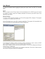
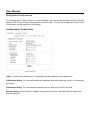
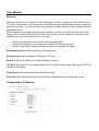
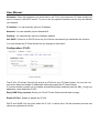
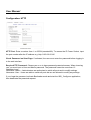
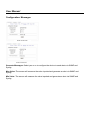
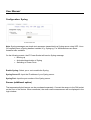
IP Power Socket
Manual
English
LINDY No. 32672/32673 IP Controlled Power Socket
www.lindy.com
© LINDY ELECTRONICS LIMITED & LINDY-ELEKTRONIK GMBH - FIRST EDITION (July 2012)
User Manual
Introduction
Thank you for purchasing the LINDY IP Controlled Power Socket. This product allows you to
control the power of your devices over an IP based network. Simply connect to a power supply and
your local network then configure the device via a web interface. Once configured, the device can
be switched using the buttons on the housing via SNMP commands or by customer created
applications.
A web interface allows you to configure the device as well as review the energy consumption and
other information. An additional temperature sensor and humidity sensor can be connected to
provide more detailed information. Each port also has a watchdog function.
Package Contents
•
•
•
IP Controlled Power Socket
CD-ROM containing software and user manual
This User Manual
Operating Instructions
Connect the IP Power Socket to the power and wait for it to boot. The LED will flash red/green
while booting and then stay red when ready to proceed. Connect one end of the Ethernet cable to
the Ethernet port of the IP Power Socket and the other end to an Ethernet port on your network.
Then connect the power cables from your device to the IP Power Socket.
LED Status
• Red: The device is not connected to Ethernet
• Orange: The device is connected to Ethernet but the TCP/IP settings are not assigned
• Green: The device is connected to Ethernet and it is ready to use
• Blinking red/green: The device is in Bootloader mode
Configuration
Bootloader Mode
In Bootloader mode it is possible to disable password function, update the firmware and restore the
default settings using the GBL_Config.exe program.
To activate Bootloader mode, press the button while restarting the device. If the device is already
running, press “select” and “OK” for 3 seconds. The Bootloader mode will be indicated by the
“BOOT-LDR” name change in the window of the GBL_Config.exe application.
User Manual
To restart the firmware without toggling the power ports, press “select” and “OK” for 3 seconds
again.
DHCP
When you switch on the IP Power Socket it will automatically look for a DHCP server and request
an available IP address. Check the IP address allocated to the device by the DHCP server is the
same after every reboot.
Network Settings
To edit the network properties manually you will need the program GBL_Config.exe. This program
is available on our website www.LINDY.com.
Activate Bootloader and run the GBL_Config.exe application. The program will automatically look
for any connected devices and display their network configuration.
If the displayed IP address matches the factory settings (192.168.0.2), there is either no DHCP
server available on the network or no free IP address could be allocated.
Enter a free IP address and then enter the Netmask address. Then save the changes by clicking on
Program Device→SaveConfig.
You must restart the IP Power Socket for any changes to take effect. Then click on Search and the
new network configuration details will be displayed.
User Manual
Configuration via web interface
To configure the IP Power Socket via a web interface, open an internet browser and input http://IP
address of IP Power Socket/ and presenter and then login. To enter the configuration menu, click
Configuration on the upper left of the screen.
Configuration: Power Ports
IPower Control Plus
Label: A name with a maximum of 15 characters can be entered for each power port.
Initialisation Status: You can define the ports switching state after powering up (on, off, remember
last state).
Initialisation Delay: You can delay the switching on of a port by up to 8191 seconds.
Repower Delay: If this function is enabled, the power port can be reactivated after a stated time
from switching off.
User Manual
Watchdog
Electrical devices can be observed while Watchdog is running. Watchdog sends ICMP pings or
TCP pings to the device, if the pings are not answered during a defined delay (timed or pings) the
power port will reset. You can also restart any attached crashed systems or NAS systems using the
Watchdog function.
When watchdog is activated it sends a ping and waits for a reply. During this time the text will be
orange. When it receives the first ping the text will turn green. When a power port has been reset
Watchdog will send a ping and wait for its first reply.
•
•
•
Green text: Watchdog is active and is receiving ping replies
Orange text: Watchdog is activating and is waiting for the first ping reply
Red text: Watchdog is active and does not receive ping replies any longer
Enable Watchdog: Activate Watchdog on this power port.
Watchdog type: Switch between ICMP ping or TCP ping.
Host IP: Enter the IP address you want Watchdog to monitor.
TCP Port: Enter the TCP port number when using TCP pings. When using ICMP pings a TCP port
number is not needed.
Ping interval: Enter the interval time between two pings.
Ping retry: Enter how many times a ping should be repeated before the power port is reset.
Configuration: IP Address
IPower Control Plus
User Manual
Hostname: Enter the Hostname you would like to use. This is the name the IP Power Socket will
use to connect to the DHCP server. Try not to use any special characters as this may de-stabilise
your network.
IP Address: You can manually input an IP address.
Netmask: You can manually input a Netmask ID.
Gateway: You can manually input the Gateway address.
Use DHCP: If there is no DHCP server on your LAN we recommend you deactivate this function.
You must restart the IP Power Socket for any changes to take effect.
Configuration: IP ACL
IPower Control Plus
The IP ACL (IP Access Control List) acts as an IP filter for your IP Power Socket. You can set it so
only active hosts and subnet IP addresses listed can access the IP Power Socket.
If you have locked yourself out by mistake, activate Bootloader mode and start the GBL_Config.exe
application, then deactivate IP ACL.
Reply ICMP-Ping requests: Select yes if the IP Power Socket should react to pings.
Enable IP Filter: Enable or disable the IP ACL.
DHCP and SNMP will only work when the IP ACL is active and if all the necessary servers and
clients are registered in this list.
User Manual
Configuration: HTTP
IPower Control Plus
HTTP Port: Enter a number from 1 to 65534 (standard:80). To access the IP Power Socket, input
the port number after the IP address e.g. http://192.168.0.2:80
Check Password on Start Page: If activated, the user must enter the password before logging in
to the web interface.
Require HTTP Password: Choose yes or no to have password protected access. When choosing
yes, you must input a User and Admin password. The password cannot be more than 15
characters long.
Username: Admin – Administrators are authorised to switch all ports and to modify settings.
Username: User – Users are able to switch all ports but are not allowed to modify any settings.
If you forget the password, activate Bootloader mode and start the GBL_Config.exe application,
then deactivate the password request.
User Manual
Configuration: Messages
IPower Control Plus
IPower Control Plus
Generate Messages: Select yes or no to configure the device to send alerts via SNMP and
Syslog.
Max Value: The sensor will measure the value inputted and generate an alert via SNMP and
Syslog.
Min Value: The sensor will measure the value inputted and generate an alert via SNMP and
Syslog.
User Manual
Configuration: Syslog
IPower Control Plus
Note: Syslog messages are simple text messages transmitted to a Syslog server using UDP. Linux
OS regularly have a Syslog daemon installed, e.g. Syslog-ng. For Windows there are some
freeware tools available.
On the following events, the IP Power Socket will send a Syslog message:
• Booting up
• Activation/deactivation of Syslog
• Switching of Power Ports
Enable Syslog: Select yes or no to enable the Syslog.
Syslog Server IP: Input the IP address of your Syslog server.
Syslog Port: Input the port number of the Syslog server.
Sensor (additional option)
The temperature/hybrid sensor can be purchased separately. Connect the sensor to the DIN socket
on the front of the device. When connected, the most recent measurement will be displayed in the
login window.
User Manual
Temperature sensor
Cable length
2m
Connection
Mini DIN
Measurement
-20°C - +100°C ±2°C (max) and ±1°C (typical)
Hybrid sensor
Cable length
2m
Connection
Mini DIN
Measurement
-20 - +80 Grad, ± 0,5°C / Moisture 0-100%
±3%
Firmware update
To update to the latest firmware start the device in Bootloader mode and start the GBL_Config.exe
application. When the program is running, the devices in the network will be listed on the left of the
screen. Select the device to be updated, click on Program Device Firmware Update and navigate to
the location of the new firmware.
Please contact LINDY for the latest version of the firmware and GBL_Config.exe.
CE/FCC & Recycling Information
CE Certification
This equipment complies with the requirements relating to Electromagnetic Compatibility Standards EN55022/EN55024
and the further standards cited therein. It must be used with shielded cables only.
It has been manufactured under the scope of RoHS compliance.
CE Konformitätserklärung
Dieses Produkt entspricht den einschlägigen EMV Richtlinien der EU für IT-Equipment und darf nur zusammen mit
abgeschirmten Kabeln verwendet werden.
Diese Geräte wurden unter Berücksichtigung der RoHS Vorgaben hergestellt.
Die formelle Konformitätserklärung können wir Ihnen auf Anforderung zur Verfügung stellen
LINDY Herstellergarantie – Hinweis für Kunden in Deutschland
LINDY gewährt für dieses Produkt über die gesetzliche Regelung in Deutschland hinaus eine zweijährige Herstellergarantie ab Kaufdatum. Die detaillierten Bedingungen dieser Garantie finden Sie auf der LINDY Website aufgelistet bei
den AGBs.
WEEE (Waste of Electrical and Electronic Equipment),
Recycling of Electronic Products
Europe, United Kingdom
In 2006 the European Union introduced regulations (WEEE) for the collection and recycling of all waste electrical and
electronic equipment. It is no longer allowable to simply throw away electrical and electronic equipment. Instead, these
products must enter the recycling process.
Each individual EU member state has implemented the WEEE regulations into national law in slightly different ways.
Please follow your national law when you want to dispose of any electrical or electronic products. More details can be
obtained from your national WEEE recycling agency.
Germany / Deutschland
Die Europäische Union hat mit der WEEE Direktive Regelungen für die Verschrottung und das Recycling von Elektround Elektronikprodukten geschaffen. Diese wurden im Elektro- und Elektronikgerätegesetz – ElektroG in deutsches
Recht umgesetzt. Dieses Gesetz verbietet das Entsorgen von entsprechenden, auch alten, Elektro- und
Elektronikgeräten über die Hausmülltonne! Diese Geräte müssen den lokalen Sammelsystemen bzw. örtlichen
Sammelstellen zugeführt werden! Dort werden sie kostenlos entgegen genommen. Die Kosten für den weiteren
Recyclingprozess übernimmt die Gesamtheit der Gerätehersteller.
France
En 2006, l'union Européenne a introduit la nouvelle réglementation (DEEE) pour le recyclage de tout équipement
électrique et électronique.
Chaque Etat membre de l’ Union Européenne a mis en application la nouvelle réglementation DEEE de manières
légèrement différentes. Veuillez suivre le décret d’application correspondant à l’élimination des déchets électriques ou
électroniques de votre pays.
Italy
Nel 2006 l’unione europea ha introdotto regolamentazioni (WEEE) per la raccolta e il riciclo di apparecchi elettrici ed
elettronici. Non è più consentito semplicemente gettare queste apparecchiature, devono essere riciclate. Ogni stato
membro dell’ EU ha tramutato le direttive WEEE in leggi statali in varie misure. Fare riferimento alle leggi del proprio
Stato quando si dispone di un apparecchio elettrico o elettronico.
Per ulteriori dettagli fare riferimento alla direttiva WEEE sul riciclaggio del proprio Stato.
LINDY No. 32672_3
st
1 Edition July 2012
www.lindy.com