1
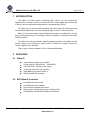
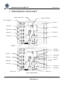
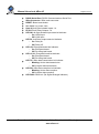
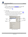
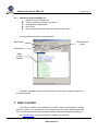
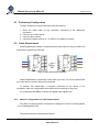
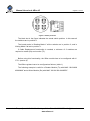
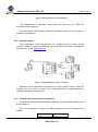
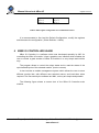
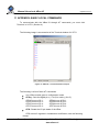
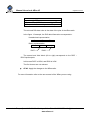
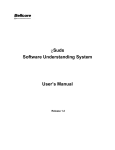
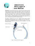
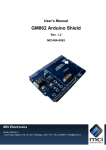
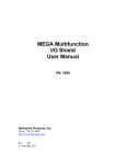
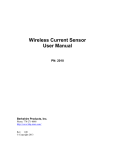
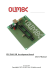
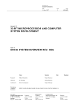
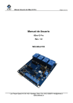
User’s Manual
XBee IO
Rev. A
MCI-MA-0085
MCI Electronics
www.olimex.cl
Luis Thayer Ojeda 0115. Of. 402 ▪ Santiago, Chile ▪ Tel. +56 2 3339579 ▪ [email protected]
MCI Ltda.
Luis Thayer Ojeda 0115. Of 402
Santiago, Chile
www.olimex.cl
Tel: +56 2 3339579
Fax: +56 2 3350589
® MCI Ltda. 2011
Attention: Any changes and modifications done to the device will void its warranty
unless expressly authorized by MCI.
Código Manual: MCI – MA - 0085
Manual Usuario de XBee IO
Página 3 de 23
1
INTRODUCTION ............................................................................................ 5
2
FEATURES .................................................................................................... 5
2.1
XBee IO ................................................................................................... 5
2.2
MCI XBeeIO Controller ............................................................................ 5
3
USER INTERFACE / DEVICE PARTS............................................................ 6
4
X-CTU ............................................................................................................ 8
4.1
4.1.1
5
5.1
Preliminary Configuration....................................................................... 10
5.2
Cable Replacement ............................................................................... 10
5.3
Module configuration for Cable Replacement ..................................... 10
Local and Remote Control ..................................................................... 12
5.3.1
Local Control ...................................................................................... 12
5.3.2
Remote Control .................................................................................. 13
5.3.3
Remote and Local Control Configuration............................................ 13
XBEE IO CONTROLLER USAGE................................................................. 14
6.1
Read and Write in XBee IO boards ........................................................ 15
6.2
Adding and removing custom remote modules ...................................... 16
6.2.1
6.3
7
Starting to work with XBee IO............................................................... 9
XBEE IO BOARD............................................................................................ 9
5.2.1
6
X-CTU usage ........................................................................................... 8
Adding a new remote module ............................................................. 16
External XML file usage ......................................................................... 18
6.3.1
Creation of a new file ......................................................................... 18
6.3.2
Pre-existing file loading ...................................................................... 19
6.4
Save changes to non-volatile memory ................................................... 19
6.5
Update Time change ............................................................................. 19
ELECTRICAL CHARACTERISTICS ............................................................. 20
Luis Thayer Ojeda 0115 Of. 402 ▪ Santiago, Chile ▪ Tel. +56 2 3339579 ▪ [email protected]
www.olimex.cl
Manual Usuario de XBee IO
Página 4 de 23
8
MECHANICHAL CHARACTERISTICS ......................................................... 20
9
PROBLEM SOLVING ................................................................................... 21
10
DOCUMENT HISTORY ................................................................................ 21
11
APPENDIX: BASIC LOCAL COMMANDS .................................................... 22
Luis Thayer Ojeda 0115 Of. 402 ▪ Santiago, Chile ▪ Tel. +56 2 3339579 ▪ [email protected]
www.olimex.cl
Manual Usuario de XBee IO
Página 5 de 23
1 INTRODUCTION
The XBee IO module allows controlling lights, valves, etc, and reading the
digital state of switches, sensors or any remote dry contact signal without the need
of wiring, doing complicated configurations or programming a device.
The XBee IO can communicate wirelessly with other XBee IO modules through
its embedded XBee radio, so it can manage a great number of remote devices.
XBee IO also allows doing Cable Replacement simply and effectively, and it’s
easily configurable using AT commands, when connected to a computer with serial
RS232 interface.
The XBee IO Controller software was developed specially for the XBee IO, and
allows reading and controlling a great number of XBee IO modules through its
intuitive graphics user interface.
There’s also a library available in C#, for Microsoft Windows.
2 FEATURES
2.1 XBee IO
4 opto-isolated inputs up to 24VDC
4 relay outputs (10A/250VAC - 10A/30VDC)
9-35 VDC/VAC - 500mA power supply.
4 switches for IN/OUT pin selection.
XBee/XBee Pro socket (Series 1).
DB9 Serial RS232 connector
2.2 MCI XBeeIO Controller
Local/Remote relay control.
Local/Remote input readings.
User module management system.
Simple and intuitive graphics user interface (GUI).
Compatibility with Microsoft Windows XP/Vista/7.
Luis Thayer Ojeda 0115 Of. 402 ▪ Santiago, Chile ▪ Tel. +56 2 3339579 ▪ [email protected]
www.olimex.cl
Manual Usuario de XBee IO
Página 6 de 23
3 USER INTERFACE / DEVICE PARTS
RS232 Serial Port
XBee Connector
CH1-4 Switchs
RL OUT 1
Opto IN 1
RL OUT 2
Opto IN 2
RL OUT 3
Opto IN 3
Opto IN 4
RL OUT 4
RESET
Vcc Jack
LED RL 1
LED RL 2
LED IN 1
LED RSSI
LED IN 2
LED RX
LED TX
LED IN 3
LED IN 4
LED RL 3
LED RL 4
LED +5V
LED +3.3V
Figure 1: XBee IO board.
Luis Thayer Ojeda 0115 Of. 402 ▪ Santiago, Chile ▪ Tel. +56 2 3339579 ▪ [email protected]
www.olimex.cl
Manual Usuario de XBee IO
Página 7 de 23
RS232 Serial Port: RS232 Communications Serial Port.
XBee Connector: XBee radio connector.
RESET: Board reset button.
Vcc Jack: Vcc power Jack.
Opto IN 1-4: Opto-isolated inputs 1-4.
RL OUT 1-4: Relay Outputs 1-4.
LED IN 1-4: Opto-isolated input state led indicator.
o On: HIGH Input.
o Off: LOW input.
LED RL 1-4: Relay output state led indicator.
o On: Relay on.
o Off: Relay off.
LED +5V: Energized board led indicator.
o On: Energized board.
o Off: De-energized board.
LED +3.3V: Energized board led indicator.
o On: Energized board.
o Off: De-energized board.
LED TX: XBee data transmission led indicator.
o Blinking: Active data transmission.
o Off: Inactive data transmission.
LED RX: XBee Data reception led indicator.
o Blinking: Active data reception.
o Off: Inactive data reception.
LED RSSI: RSSI led. (Rx Signal Strength Indicator)
Luis Thayer Ojeda 0115 Of. 402 ▪ Santiago, Chile ▪ Tel. +56 2 3339579 ▪ [email protected]
www.olimex.cl
Manual Usuario de XBee IO
Página 8 de 23
4 X-CTU
X-CTU is a software developed by Digi International which allows working
graphically with XBee, and also includes a console for AT commands. X-CTU
allows configuring the XBee registers in a very simple and intuitive way.
X-CTU can be downloaded here.
4.1 X-CTU usage
XBee IO is programmed via its built-in serial connector. A software like X-CTU
could be used to do this, or HyperTerminal, through AT commands.
The XBee IO module has three basic functionalities: Cable Replacement, Local
Control and Remote Control. These topics will be explained in section 5.
The following image shows the X-CTU main window.
Modem
Configuration
Terminal
Label
Test/Query
button
Serial Port
Selection
Figure 2: X-CTU main window.
Luis Thayer Ojeda 0115 Of. 402 ▪ Santiago, Chile ▪ Tel. +56 2 3339579 ▪ [email protected]
www.olimex.cl
Manual Usuario de XBee IO
4.1.1
Página 9 de 23
Starting to work with XBee IO
Select the correct Serial Port.
Test the module by clicking Test/Query.
Click Modem Configuration.
Click Read.
After changes have been done, click Write to save them.
A configuration example is shown herewith:
Show Defaults
button
Write button
Read button
XBee
module
registers
Figure 3: XBee IO configuration.
The XBee registers can be easily modified by clicking them and selecting one of
the listed options.
5 XBEE IO BOARD
The XBee IO module was designed to provide 3 basic functionalities to satisfy
different needs. The modules can be configured act as Cable Replacement and
both local and remote (wireless) modules can be controlled through the serial port.
An XBee Explorer connected to the PC could be used as well.
Luis Thayer Ojeda 0115 Of. 402 ▪ Santiago, Chile ▪ Tel. +56 2 3339579 ▪ [email protected]
www.olimex.cl
Manual Usuario de XBee IO
Página 10 de 23
5.1 Preliminary Configuration
To begin using the module a few steps must be followed:
1. Place the XBee radio on the connector, according to the silkscreen
orientation.
2. Connect dry contact inputs
3. Connect relay outputs.
4. Connect the power source (9 - 35 VDC) to the XBee IO module.
5.2 Cable Replacement
Cable Replacement makes a reception board relay output to copy the state of a
transmission board input relay pin.
Figure 4: Cable Replacement schematic.
Cable Replacement is especially useful when you have 2 or more modules and
you want them to act as if they were connected.
To achieve this functionality a computer connected to the device is not
necessary. After the configuration the modules will be working on their own.
It is noteworthy that XBee IO works with digital input signals only.
5.2.1
Module configuration for Cable Replacement
The XBee IO board includes 4 switches to change the module to Writing Mode
(Tx) or Reading Mode (Rx).
The switch positions are defined as follows:
Luis Thayer Ojeda 0115 Of. 402 ▪ Santiago, Chile ▪ Tel. +56 2 3339579 ▪ [email protected]
www.olimex.cl
Manual Usuario de XBee IO
Página 11 de 23
Figure 5: Switch positions.
The black dot in the figure indicates the actual switch position. In this case all
the switches are in position 0.
The board works in Reading Mode if all the switchs are in position 0, and in
Writing Mode if all are in position 1.
If Cable Replacement functionality is needed, a minimum of 2 modules are
required: a reader (Rx) and a writer (Tx).
Before using this functionality, the XBee module has to be configured with XCTU. (section 4)
The XBee registers has to be configured as follows: (table 1)
The following example is valid for a Reader Module (Tx) with MAC “0013A200
406628A9” and a Writer Module (Rx) with MAC “0013A 200 40662B72”.
Luis Thayer Ojeda 0115 Of. 402 ▪ Santiago, Chile ▪ Tel. +56 2 3339579 ▪ [email protected]
www.olimex.cl
Manual Usuario de XBee IO
Página 12 de 23
Output Module (MAC: 0013A200
406628A9)
ID = 3332
DH = 13A200
DL = 40662B72
D8 = 0
D7 = 4
D6 = 4
D5 = 4
D4 = 4
D3 = 4
D2 = 4
D1 = 4
D0 = 4
IT = 14
IC = FF
IR = FF
IA = FFFF
PT = 0
RP = 0
Input Module (MAC: 0013A200
40662B72)
ID = 3332
DH = 13A200
DL = 406628A9
D8 = 0
D7 = 3
D6 = 3
D5 = 3
D4 = 3
D3 = 3
D2 = 3
D1 = 3
D0 = 3
IT = 14
IC = FF
IR = FF
IA = FFFF
PT = 0
RP = 0
Table 1: XBee register configuration for Cable Replacement.
5.3 Local and Remote Control
The following configurations allow to control modules through the serial port
included in the board.
5.3.1
Local Control
This configuration allows the user to control the output relay states and to read
the opto-isolated input states of the board connected to the computer.
Luis Thayer Ojeda 0115 Of. 402 ▪ Santiago, Chile ▪ Tel. +56 2 3339579 ▪ [email protected]
www.olimex.cl
Manual Usuario de XBee IO
Página 13 de 23
Figure 6: Serial Port local Control schematic.
This configuration is especially useful when you have only one XBee IO,
connected to the computer.
Command line AT commands or XBee IO Controller (section 7) can be used to
control a local XBee IO.
5.3.2
Remote Control
This configuration is the most powerful, as it allows the user to control a great
number of XBee IO remote modules through a local XBee IO module connected to
the computer. (or an XBee Explorer)
Figure 7: Serial Port Remote Control schematic.
Remote Control is especially useful when you have a great number of XBee IO
modules and you want to control them and read their pin states separately,
remotely through their wireless link.
5.3.3
Remote and Local Control Configuration
If remote/local control functionalities are required, all the modules switches must
be at position 0.
Also, it is necessary to configure the XBee registers with X-CTU (section 4) as
follows:
D8 = 0
D3 = 3
D7 = 4
D2 = 3
Luis Thayer Ojeda 0115 Of. 402 ▪ Santiago, Chile ▪ Tel. +56 2 3339579 ▪ [email protected]
www.olimex.cl
Manual Usuario de XBee IO
Página 14 de 23
D6 = 4
D5 = 4
D4 = 4
D1 = 3
D0 = 3
AP = 1
Table 3: XBee register configuration for Local/Remote Control.
It is recommended to first load the Default Configuration, modify the registers
and then save the configuration. (Show Defaults -> Write)
6 XBEE IO CONTROLLER USAGE
XBee IO Controller is a software which was developed specially by MCI for
controlling the XBee IO module. It has a graphics user interface which enables the
user to control a great number of XBee IO modules in a very simple and intuitive
way.
The program allows to control the relays states and to read the states of the
opto-isolated inputs of the selected module. (local or remote)
It also includes a module management system which allows the user to store
different module lists, with different user selected names, and load them when
required. The files used by the software are XML, so they are simple and portable.
The following figure shows a screen shot of the XBee IO Controller main
window:
Luis Thayer Ojeda 0115 Of. 402 ▪ Santiago, Chile ▪ Tel. +56 2 3339579 ▪ [email protected]
www.olimex.cl
Manual Usuario de XBee IO
Página 15 de 23
Module
Management
System
Module
Selection
Port
Selection
Save changes
to non volatile
memory
Open/Close
Port
Update Time
Modifications
ON/OFF Relay
buttons
Figure 8: XBee IO Controller main window.
It is important to mention that before using the program, Microsoft .NET
Framework 4 must be correctly installed on the computer. You can get it here.
6.1 Read and Write in XBee IO boards
To work with XBee IO Controller a few steps must be followed:
1. Select the desired serial port at the upper left corner of the window.
2. Click Open/Close Port.
3. Select the module to use. Only the local module will be listed initially.
The program updates the state of the LEDs in the screen automatically every 5
seconds (default value). This time interval can be changed if required by changing
its value in the upper left corner of the window. (Update Time [s])
Luis Thayer Ojeda 0115 Of. 402 ▪ Santiago, Chile ▪ Tel. +56 2 3339579 ▪ [email protected]
www.olimex.cl
Manual Usuario de XBee IO
Página 16 de 23
To turn on and off the relays of the selected module, simply click the
corresponding RL1-RL4 button at the right part of the window.
6.2 Adding and removing custom remote modules
To access the module edition menu, click the Modules label.
Figure 9: Module Edition window.
The interface has text fields for the alias (name) and the MAC address of the
module. This enables the user to fill in the parameters only once and then forget
about them. To use the module later the user can simply select it by its alias from
the module list menu when required.
Every time a new module is added, the software will automatically save its data
on in an external XML file.
The modules can also be edited or even deleted if necessary
6.2.1
Adding a new remote module
-
-
Select New Module…
Enter a name (any) and the Serial Address High (SH) and Serial Address
Low (SL) numbers. These numbers can be seen through X-CTU or directly
on the back of the XBee radio. (figure 11)
Click Save.
Luis Thayer Ojeda 0115 Of. 402 ▪ Santiago, Chile ▪ Tel. +56 2 3339579 ▪ [email protected]
www.olimex.cl
Manual Usuario de XBee IO
Página 17 de 23
Figure 10: SH and SL on the back of the XBee radio.
The added modules will be stored to the hard drive, and could be used the next
time you open the program.
Figure 11: Adding an example module.
To remove a module just select it and then click Remove.
Luis Thayer Ojeda 0115 Of. 402 ▪ Santiago, Chile ▪ Tel. +56 2 3339579 ▪ [email protected]
www.olimex.cl
Manual Usuario de XBee IO
Página 18 de 23
6.3 External XML file usage
The program works with XML files to store the custom modules: An alias
(custom name) is associated to every MAC direction.
The user can create different module lists, for example for different industrial
plants, and load the corresponding file in situ.
Also, the software includes a file management system which enables the user to
create new files or load pre-existing files.
It is important to mention that the program uses a default file Modules.xml. The
program will try to find the file every time the program is executed. If it is not found,
the program will create a new one in the folder where the executable file is located.
6.3.1
Creation of a new file
-
Click Modules.
Select New File…
Enter a name for the new file and then accept.
After the previous steps a new default file is created.
Figure 12: Creation and Load of external XML files.
Luis Thayer Ojeda 0115 Of. 402 ▪ Santiago, Chile ▪ Tel. +56 2 3339579 ▪ [email protected]
www.olimex.cl
Manual Usuario de XBee IO
Página 19 de 23
If you want to use pre-existent files, you will have to load them by clicking Load
File…
6.3.2
Pre-existing file loading
-
Click Modules.
Click Load File…
Select the desired file and then accept.
The program will load to memory all the modules stored in the file, for their use
with the graphics user interface.
6.4 Save changes to non-volatile memory
The software includes the capability of writing the relay outputs states to the
non-volatile memory of the XBee. This enables the module to “remember” the
states of its pins after a reset or power supply failures.
To save changes to the non-volatile memory click Save Changes. The program
will show an “Ok” message if the command succeeded.
6.5 Update Time change
After a serial port is opened, the program will start to read the states of the optoisolated input pins of the selected module, constantly. The time interval is given by
the Update Time parameter.
The default value of the Update Time parameter is 5 [s], but it can be changed
in the textbox at the left corner of the window, whenever required.
Only values between 1 and 999[s] are valid.
Luis Thayer Ojeda 0115 Of. 402 ▪ Santiago, Chile ▪ Tel. +56 2 3339579 ▪ [email protected]
www.olimex.cl
Manual Usuario de XBee IO
Página 20 de 23
7 ELECTRICAL CHARACTERISTICS
Power supply voltage range: 9-35 VDC/VAC
Average power consumption: ~50mA idle. ~250 mA with the 4 relays ON. (@
9V)
8 MECHANICHAL CHARACTERISTICS
Dimensions 100x80 [mm]
Luis Thayer Ojeda 0115 Of. 402 ▪ Santiago, Chile ▪ Tel. +56 2 3339579 ▪ [email protected]
www.olimex.cl
Manual Usuario de XBee IO
Página 21 de 23
9 PROBLEM SOLVING
Most frequent problems:
The board stops responding in AT command mode:
Send a +++ command to reactivate it. The XBee radio goes to low power
mode after 10 [s] if no commands are received. (Default time)
The board does not respond to 802.15.4 frames:
Check that the API mode is activated with X-CTU (AP=1)
The board does not turn on/off a relay:
Check the CH1-CH4 switch positions.
10 DOCUMENT HISTORY
Revision Date
Edited by
1.0
March 7, 2011
Carlos Apablaza B
1.1
September 15, 2011
Eduard Martin
Description/Changes
Initial Version of the
Document
Correction of cable
replacement
configuration
Luis Thayer Ojeda 0115 Of. 402 ▪ Santiago, Chile ▪ Tel. +56 2 3339579 ▪ [email protected]
www.olimex.cl
Manual Usuario de XBee IO
Página 22 de 23
11 APPENDIX: BASIC LOCAL COMMANDS
To communicate with the XBee IO through AT commands, you must click
Terminal, in X-CTU. (Section 4)
The following image is a screenshot of the Terminal window of X-CTU.
Figure 13: XBee IO – X-CTU Interaction example.
The following is a list of basic AT commands.
+++: XBee module goes to configuration mode.
ATDxy : Sets the digital pin x ( 0 to 8) in mode y (0 to 5)
ATD45 turns on RL 1.
ATD44 turns off RL 1.
ATD55 turns on RL 3.
ATD54 turns off RL 3.
ATD65 turns on RL 4.
ATD64 turns off RL 4.
ATD75 turns on RL 2.
ATD74 turns off RL 2.
ATIS: Reads the I/O pin states of the XBee.
ATIS returns 3 registers in hexadecimal codification, with the following
format:
Luis Thayer Ojeda 0115 Of. 402 ▪ Santiago, Chile ▪ Tel. +56 2 3339579 ▪ [email protected]
www.olimex.cl
Manual Usuario de XBee IO
Página 23 de 23
Number of samples<CR>
channel mask<CR>
DIO data<CR> (If DIO lines are enabled<CR>
<CR> (end of data noted by extra <CR>)
The returned DIO data value is the state of the pins of the XBee radio.
In the figure 13 example, the DIO data information corresponds to:
Hexadecimal representation
0
7
F
Binary representation
0000 0111
DIO7
1111
DIO0
The second and third block (left to right) corresponds to the DIO7 –
DIO0 input/outputs.
In this case DIO7 is HIGH, and DIO0 is LOW.
The first 4 zeros are not relevant.
ATAC: Apply the changes to the XBee radio.
For more information refer to the user manual of the XBee you are using.
Luis Thayer Ojeda 0115 Of. 402 ▪ Santiago, Chile ▪ Tel. +56 2 3339579 ▪ [email protected]
www.olimex.cl