1
Active@ UNDELETE User Guide
| Contents | 2
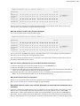
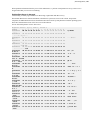
Contents
Legal Statement.........................................................................................................5
Active@ UNDELETE overview.............................................................................. 6
Getting started with Active@ UNDELETE........................................................... 7
Active@ UNDELETE views and windows......................................................................................................... 8
Recovery Explorer view....................................................................................................................................... 8
Welcome view.................................................................................................................................................... 10
Using Active@ UNDELETE..................................................................................11
Recover deleted files and folders....................................................................................................................... 12
Recover files and folders from existing volume....................................................................................12
Recover files from deleted (damaged) partitions................................................................................... 17
Recover files by their signatures............................................................................................................22
Working with a corrupted RAID........................................................................................................... 23
Recover detected files.............................................................................................................................24
Decrypt recovered files...........................................................................................................................25
Restore partitions................................................................................................................................................ 27
Scan for deleted partitions and files by their signatures........................................................................27
Work with device scan results............................................................................................................... 29
Edit the boot sector template in detected partition................................................................................ 31
Restore detected partition....................................................................................................................... 32
Using scan results............................................................................................................................................... 33
Preserve scan results...............................................................................................................................34
Stop and resume interrupted scan.......................................................................................................... 35
File preview............................................................................................................................................ 36
File filter toolbar control........................................................................................................................ 38
Filter detected partitions by certainty.....................................................................................................39
Search for deleted files and folders................................................................................................................... 40
Search results view................................................................................................................................. 42
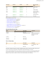
File signatures..................................................................................................................................................... 43
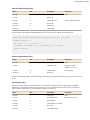
Custom (user defined) file signature templates......................................................................................43
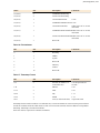
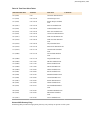
Supported file signatures........................................................................................................................ 51
Working with disk images................................................................................................................................. 54
Create a Disk Image............................................................................................................................... 55
Open Disk Image....................................................................................................................................57
Verify Disk Image.................................................................................................................................. 59
Using virtual storages......................................................................................................................................... 59
Create virtual disk...................................................................................................................................59
Virtual partitions..................................................................................................................................... 60
Virtual RAID.......................................................................................................................................... 63
Active@ UNDELETE wizards overview..............................................................66
File recovery wizards......................................................................................................................................... 66
Recover deleted files wizard.................................................................................................................. 66
| Contents | 3
Recover files detected by their signatures wizard................................................................................. 68
Recover files from a damaged partition wizard.....................................................................................70
Recover files from a formatted partition wizard....................................................................................72
Recover files from a deleted partitions wizard...................................................................................... 74
Recover files from a physical disk wizard.............................................................................................76
Disk image wizards............................................................................................................................................ 76
Create a disk image wizard.................................................................................................................... 76
Open a disk image wizard......................................................................................................................78
Verify a disk image wizard.................................................................................................................... 79
Partition management wizards............................................................................................................................81
Restore a deleted partition wizard..........................................................................................................81
Create a new partition wizard................................................................................................................ 82
Create a virtual RAID wizard............................................................................................................................ 83
Advanced tools........................................................................................................ 86
Disk Editor.......................................................................................................................................................... 86
Opening disks, volumes (logical drives) and files with Disk Editor..................................................... 86
Working with editor............................................................................................................................... 88
Using Templates..................................................................................................................................... 97
Disk Editor tools and views................................................................................................................. 101
Searching in Disk Editor...................................................................................................................... 104
Partition Manager..............................................................................................................................................107
Initialize new disk (physical device)....................................................................................................107
Partition manipulation...........................................................................................................................108
Disk editing...........................................................................................................................................112
File Organizer................................................................................................................................................... 114
Organize files in a view....................................................................................................................... 115
File Organizer view.............................................................................................................................. 116
Create custom file organizing rule....................................................................................................... 117
File renaming patterns by file type...................................................................................................... 118
File attributes and meta tags................................................................................................................ 119
Forensic Report.................................................................................................................................................122
Investigate volumes.............................................................................................................................. 123
Appendix................................................................................................................ 126
Searching patterns.............................................................................................................................................126
Application log..................................................................................................................................................126
Property views.................................................................................................................................................. 128
Hardware diagnostic file...................................................................................................................................129
Application preferences........................................................................................130
Knowledge Base.................................................................................................... 136
Knowledge Base overview............................................................................................................................... 136
Hardware and Disk Organization..................................................................................................................... 136
Hard Disk Drive Basics........................................................................................................................136
Master Boot Record (MBR).................................................................................................................138
Partition Table.......................................................................................................................................140
Disk arrays (RAID's)........................................................................................................................................ 144
Logical Disk Manager (LDM) overview......................................................................................................... 145
File Systems...................................................................................................................................................... 146
Windows NT File System (NTFS).......................................................................................................146
| Contents | 4
File System (FAT)................................................................................................................................ 155
Extended File System (exFAT)............................................................................................................167
Data Recovery Concept.................................................................................................................................... 183
File Recovery Process.......................................................................................................................... 183
Partition Recovery Process................................................................................................................... 190
Glossary.............................................................................................................................................................199
Uninstall Active@ UNDELETE.......................................................................... 202
| Legal Statement | 5
Legal Statement
Copyright © 2015, LSOFT TECHNOLOGIES INC. All rights reserved. No part of this documentation may be
reproduced in any form or by any means or used to make any derivative work (such as translation, transformation, or
adaptation) without written permission from LSOFT TECHNOLOGIES INC.
LSOFT TECHNOLOGIES INC. reserves the right to revise this documentation and to make changes in content from
time to time without obligation on the part of LSOFT TECHNOLOGIES INC. to provide notification of such revision
or change.
LSOFT TECHNOLOGIES INC. provides this documentation without warranty of any kind, either implied or
expressed, including, but not limited to, the implied warranties of merchantability and fitness for a particular purpose.
LSOFT may make improvements or changes in the product(s) and/or the program(s) described in this documentation
at any time.
All technical data and computer software is commercial in nature and developed solely at private expense. As
the User, or Installer/Administrator of this software, you agree not to remove or deface any portion of any legend
provided on any licensed program or documentation contained in, or delivered to you in conjunction with, this User
Guide.
LSOFT.NET logo is a trademark of LSOFT TECHNOLOGIES INC.
| Active@ UNDELETE overview | 6
Active@ UNDELETE overview
Active@ UNDELETE is an advanced data recovery tool designed to recover data lost or deleted data, or even
information from formatted hard disks.
Active @ UNDELETE is a software application designed to help you restore your lost data from deleted files,
folders or even partitions.
Main Features short list
•
•
•
•
•
•
•
•
•
•
Recover deleted files and folders.
Detect deleted partitions and restore them or recover data from them.
Create a Disk Image for safe data restoration.
Perform an Advanced Scan and organize the result using Scan Result view.
Restore data from damaged RAID-system drives.
Work and recover data form dynamic RAID.
Manage existing partitions or create new once using Partition Manager tool.
Edit disk content with the advanced Disk Editor tool.
Preview files before restoring.
Supports HDD's larger then 2TB.
List of supported File Systems
•
•
•
•
•
•
•
•
•
NTFS
NTFS + EFS
FAT
FAT32
exFAT
Mac OS HFS+
Linux Ext2/Ext3/Ext4
Unix UFS
BtrFS
General system requirements
•
•
•
•
•
•
•
Windows 10, Windows 8, Windows 7, Windows 2000, Windows 2003, Windows Server 2008, Windows XP,
WinPE
Administrators privileges required to install and run software
Pentium processor or compatible
60 MB available on hard disk
2048 MB of RAM or more
Internet Explorer 8 or later, Google Chrome, Mozilla Firefox 1.0 or later
Mouse or other pointing device
| Getting started with Active@ UNDELETE | 7
Getting started with Active@ UNDELETE
Active@ UNDELETE is designed to explore and browse all data storage devices on your computer in different ways
to find and recover lost data. All information in the application is organized in tabbed views that provide easy access
to information for different purposes.
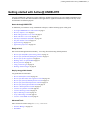
New to Active@ UNDELETE?
To familiarize you with the Active@ UNDELETE workspace, read the following topics in this guide:
•
•
•
•
•
•
•
•
Active@ UNDELETE views and windows on page 8
Recovery Explorer view on page 8
Work with logical drive scan results on page 16
Work with device scan results on page 19
Search for deleted files and folders on page 40
File filter toolbar control on page 38
Application log on page 126
Application preferences on page 130
Ready to Use?
Start with essential application functionality - recovering files and restoring deleted partitions.
•
•
•
•
•
•
•
Recover files and folders from existing volume on page 12
Recover files from deleted (damaged) partitions on page 17
Recover files by their signatures on page 22
Working with a corrupted RAID on page 23
Restore partitions on page 27
Using virtual storages on page 59
Working with disk images on page 54
Step-by-step guided wizards
Use guided tools for main tasks
•
•
•
•
•
•
•
•
•
•
•
Recover deleted files wizard on page 66
Recover files detected by their signatures wizard on page 68
Recover files from a formatted partition wizard on page 72
Recover files from a deleted partitions wizard on page 74
Recover files from a physical disk wizard on page 76
Restore a deleted partition wizard on page 81
Create a new partition wizard on page 82
Create a disk image wizard on page 76
Open a disk image wizard on page 78
Verify a disk image wizard on page 79
Create a virtual RAID wizard on page 83
Advanced Tools
Move forward for advance using of Active@ UNDELETE:
•
•
Partition Manager on page 107
Disk Editor
| Getting started with Active@ UNDELETE | 8
•
•
File Organizer on page 114
Forensic Report on page 122
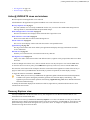
Active@ UNDELETE views and windows
Brief description of main application views and tools
All information in the application is organized in tabbed views. Four of the main views are:
Recovery Explorer view on page 8
The main (default) view of Active@ UNDELETE. In this view you can see all available Data Storage Devices
and Logical Drives, Assembled RAIDs and opened Disk Images.
Work with logical drive scan results on page 16
The Drive Scan Result View displays all files detected after a logical drive scan.
Work with device scan results on page 19
Shows scan results made in context of Data Storage Device.
Search results view on page 42
This view is used to display search results after the search in corresponded context.
Application log on page 126
This log screen monitors each action taken by the application and displays messages, notifications and other
service information.
Welcome view on page 10
Summary view with main tools, wizards and recent activity shortcuts.
File Organizer view on page 116
Utility view used to collect detected files from different sources, organize in file groups (folder) and recover them
all at once.
To browse through each of these views, click on each tab in turn. You may also open a view from the View menu.
To close the current view at any time, press CTRL+F4. To open any closed view, select it from the View menu.
The status bar, at the bottom of the workspace shows the current status of the application or status of the activity in
progress. When Active@ UNDELETE is idle and ready to perform an operation, the status displays "Ready".
To toggle the status bar click View > Status Bar.
Note: When you run Active@ UNDELETE, the application gathers information about disks and partitions
available to the system. During this preliminary operation, the status bar displays "Initializing..." and
application prevents most other operations from starting. Application Log View shows detailed information
about the initialization stage.
To modify the information displayed in columns in a table list, right-click any column header and select or clear
columns from context menu.
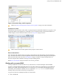
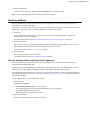
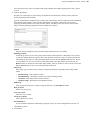
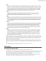
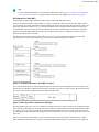
Recovery Explorer view
Active@ UNDELETE is an advanced data recovery tool designed to recover data lost or deleted data, or even
information from formatted hard disks.
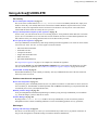
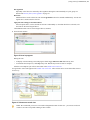
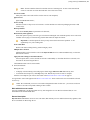
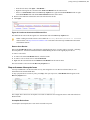
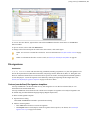
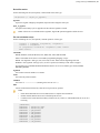
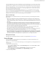
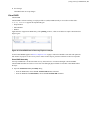
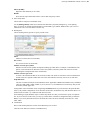
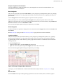
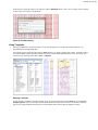
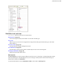
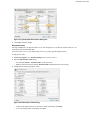
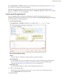
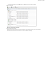
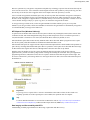
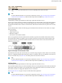
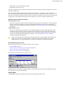
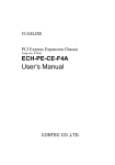
The main view in Active@ UNDELETE is Recovery Explorer view. This is the default view that you see after the
application starts. It displays the hierarchical structure of all devices and drives, Virtual RAIDs or virtual devices and
opened disk images. Scan results also appear here if you scan a device. To collapse or expand an item in this tree,
click the arrow sign next to the item name.
| Getting started with Active@ UNDELETE | 9
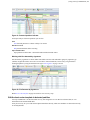
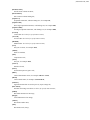
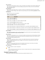
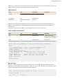
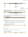
Figure 1: Recovery Explorer example
Recovery Explorer shows its content in several modes, that can be switched by view's toolbar drop-down menu button
View.
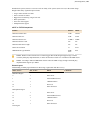
Expert Device View (default)
At this mode, all available data storage devices with logical drives are present.
Local Drive View
At this mode, only accessible logical drives are present.
Partition View
Use this mode to show hierarchy of data storage devices partitioning (including extended partitions on MBR
devices).
Enhanced View
At this mode, all available Data Storage Devices with hierarchy of partitions and logical drives are present; Use
this mode for advanced features, such as Advanced Device Scan or Virtual Partition Management.
Show system drive
Hides or shows system drive for safety reason.
Show Local Network
Hides or shows shared network data storage resources.
To perform an action on any item (data storage device, logical drive etc.) select this and choose a command from:
•
•
•
Toolbar at the top of the view;
Menu Actions;
or from the right-click context menu.
The Properties Panel displays default properties for each selected item. Updates to these properties appear
dynamically along with commands and activities performed in the workspace. To toggle the Properties Pane click
View > Properties pane. Read Property views on page 128 for more info.
| Getting started with Active@ UNDELETE | 10
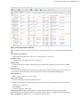
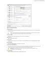
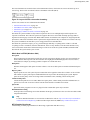
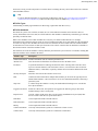
Welcome view
Active@ UNDELETE is an advanced data recovery tool designed to recover data lost or deleted data, or even
information from formatted hard disks.
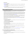
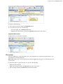
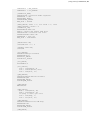
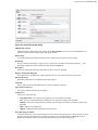
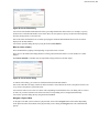
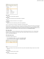
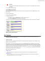
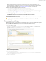
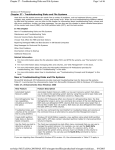
This view appears when application starts and contains shortcut buttons for main tools, wizards and recent activity
shortcuts divided in groups for easy access to Active@ UNDELETE features at application start.
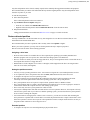
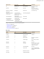
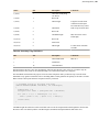
Figure 2: Default welcome view
Getting started
Contains most general starting points for file recovery and partition restoration.
Data Recovery Wizards
As it stated, on this page user can start file recovery wizards designed for different scenarios.
Partition Management
Allows to open Partition Manager or start wizards to create or format partitions.
Disk Image Management
Let to run wizards to create, open or verify disk images.
Advanced Tools
Advanced tools like open disks in Disk Editor, create Virtual RAID or decrypt files.
Support
Customer support and documentation.
Version Info
Contains version history and information about recent updates.
Recent files
Group of shortcut links to open recently used Disk Images, sessions or saved scan results.
| Using Active@ UNDELETE | 11
Using Active@ UNDELETE
File recovery
Recover deleted files and folders on page 12
This is one of the essential features of Active@ UNDLETE. To recover accidentally deleted files, simply scan
the drive where they were deleted, then browse scan results in familiar Windows-explorer like browser, search
and filter results, select required files and recover them to safe location. You can preview scan results first to
confirm that the detected files are exactly the once you need.
Scan for deleted partitions and files by their signatures on page 18
In some cases, you seek files from drives are not existing anymore - those partitions either deleted or overwritten
by new one. It is still chance to recover some files in such condition! You have to located deleted partitions first
and scan them as they are existing partitions and recover all detected files you need;
Recover files by their signatures on page 22
Active@ UNDELETE can find files by their unique format specification (signature) even if file can not be found
in Partition File Table. For now, we can recognise various file formats:
•
•
•
•
•
•
Microsoft Office Documents.
Formatted Text files.
Compressed Archives.
Images and Camera Raw files.
Music and Videos.
QuickTime Multimedia files.
See Supported file signatures on page 51 for complete list of default file signatures.
User can create custom, user defined File Signature Templates to be used to detect files during low level disk
scan by customized file signatures. See Custom (user defined) file signature templates on page 43 for details.
Virtual RAID Assembly on page 63
Disassembled RAID array can be virtually recreated by Active@ UNDELETE and some of the files located on
these array can be recovered;
Partition restoration and management
Restore detected partition on page 32
You partition is gone? Accidentally deleted by user or by malicious software it is still chance it can be restored if
not overwritten yet. Scan hard disk for deleted partition and use Restore command to get your partition back! We
recommend you to restore your important data first;
Rollback partition changes on page 111
If all your manipulation with hard disk partitioning was made by using Active@ UNDELETE you can rollback
(e.g. undo) all changes you have made in few clicks.
Partition Manager on page 107
By using small Partition Manager module in Active@ UNDELETE you can execute basic partition
manipulation such as creation, formatting and delete. It can be useful during partition recovery operations;
Disk Images
Working with disk images on page 54
We advice to create Disk Image of a drive you work with before any actual recovery or partition restoration. It
may prevent loosing data in accidental writing of cumulative hardware malfunction;
| Using Active@ UNDELETE | 12
Advanced tools
Edit boot sectors on page 112
For advanced operations, you can manipulate partition table and boot sector attributes by using template dialogs;
Disk Editor on page 86
Advanced and integrated in Active@ UNDELETE environment disk editor - read and write data on low level.
File preview on page 36
To confirm that the file you have detected is exactly the file you seek, you can use File Preview feature before the
actual recovery. It also helps to confirm file integrity first. Some restriction applies for DEMO version;
Recover deleted files and folders
Active@ UNDELETE is an advanced data recovery tool designed to recover data lost or deleted data, or even
information from formatted hard disks.
In nutshell, file recovery requires scan of disk for deleted files first, review scan results and at the end - recover
selected files to safe location. Scan can be applied on existing logical drive (or volume) in case when file was simply
deleted for any reason. For more complex cases, when files were on deleted or damaged partition, a disk itself must
be scanned for these deleted partition first, then in its turn scan detected partitions for files. And finally in the most
difficult case, when files were lost on damaged or undetectable partition or even from unpartitioned disk at all, disk
surface must be scanned for deleted files by using unique files signatures.
Some times your RAID controller dismount HDD array and you loosing access to your data. In this case, you can
attach disks from array directly to the motherboard, use Active@UNDELETE to assemble virtual RAID from these
disks and scan volumes on assembled array for files and recover them to safe location.
Some times files needs to be recovered from encrypted source to some intermediate data storage that not supports
encryption (e.g. FAT32 formatted Flash card). For that you can use Decrypt recovered files on page 25 tool for a
final recovery touch.
Recover files from existing volumes
Use this method for simplest file recovery. Recommended for most cases. Recover files by their signatures can be
also applied for better results.
Recover files from deleted (damaged) partitions
If files where lost on deleted (damaged) partition
Recover files by their signatures
Use this technique to recover files from formatted partition or from unallocated (unpartitions) space on disk.
Recover files from broken RAID
Create Virtual RAID from disassembled disks to be able to scan them for deleted (unaccessable) files and
folders,s
You can also restore entire partition, if its was deleted and detected in a good shape for recovery. However we are
strongly recommend to recover files first to another location.
If you have a difficulties to determine the best scenarios, try Active@ UNDELETE wizards overview on page 66 self guided step-by-step set of tools.
After you can see partitions on a device, the file recovery process consists of three stages.
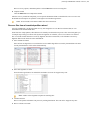
Recover files and folders from existing volume
Active@ UNDELETE is an advanced data recovery tool designed to recover data lost or deleted data, or even
information from formatted hard disks.
In most used cases, files needs to be recovered from existing disk volumes (logical drives) after accidental deletion or
due to software malfunction. To recover detected files:
1. Scan volume
| Using Active@ UNDELETE | 13
In order to recover deleted files from existing logical drives (volumes) the must be scanned first individually or
several at once. For exact volume scan procedure read: Scan a volume (logical drive) for deleted files on page
13.
2. Analyze Scan Results
A Logical Drive scan result appears in the Work with logical drive scan results on page 16 where results can
be reviewed and files selected for recovery.
File Grouping - detected files can be grouped for better analyzing by using the Group By drop-down menu in the
toolbar. Detected files can be grouped by:
•
•
•
File Extensions;
By Associated Applications;
By Date (Created Date, Modified Date and Accessed or Deleted Date);
Search and Filtering - detected files can be filtered by name, extension or deleted status by using the File filter
toolbar control on page 38. For more narrow results Search for deleted files and folders on page 40 can be
used.
3. Recover files
You may recover damaged or deleted files and folders directly from any view that presents files, such us:
•
•
•
Work with logical drive scan results on page 16;
Work with device scan results on page 19
Search results view on page 42.
Files also can be organized in groups before actual recovery by using File Organizer on page 114 tool.
For more information about file recovery options read: Recover detected files on page 24 article.
4. Repeat [optional]
Repeat steps 1-3 for different volumes using different scan attributes for better results if necessary.
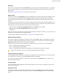
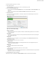
Scan a volume (logical drive) for deleted files
Active@ UNDELETE is an advanced data recovery tool designed to recover data lost or deleted data, or even
information from formatted hard disks.
Scanning logical drives is a required step for recovering files and folders. During the scan all deleted (and existing)
file and folders are detected. The results of a logical drive scan are displayed in a separate tabbed views: Volume scan
result view.
Detected partitions, after disk scan, can be scanned in they turn in a same manner as live volumes (logical drives).
Read Scan for deleted partitions and files by their signatures on page 18for details.
| Using Active@ UNDELETE | 14
To scan a volume (logical drive):
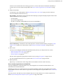
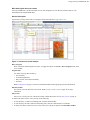
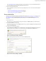
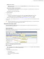
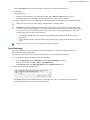
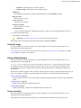
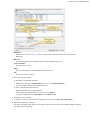
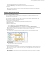
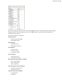
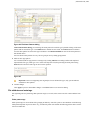
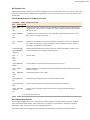
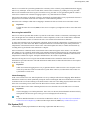
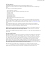
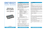
1. Initiate volume scan
From Recovery explorer:
•
•
•
Click Undelete Files button in view's toolbar or
Select logical drive and click Scan button in view's toolbar or
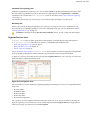
Use context menu Scan command
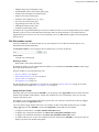
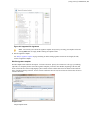
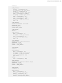
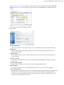
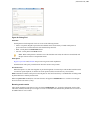
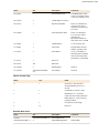
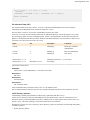
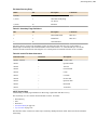
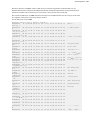
Figure 3: Initiate volume scan
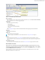
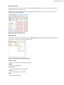
Then Scan Volumes dialog should appear.
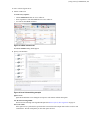
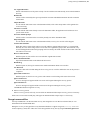
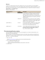
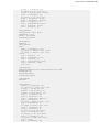
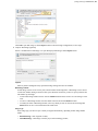
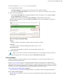
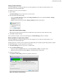
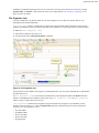
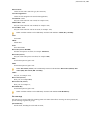
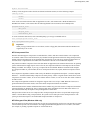
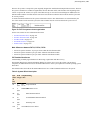
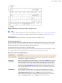
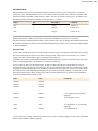
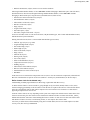
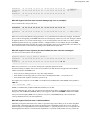
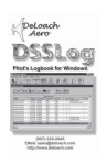
2. Specify scan attributes
Figure 4: Scan Volume dialog example
Ignore errors
Ignore Read and Write errors during the scan process and continue without interruption.
Use advanced scan algorithm
Slower but more thorough scan algorithm. Required for Recover files by their signatures on page 22.
Save scan results
If this option is on, a path must be specified where scan results with a unique name will be saved for each
scanned drive. Provide valid path if you have this option selected.
| Using Active@ UNDELETE | 15
File signatures
Optionally select files to be detected by their signatures during the scan individually or by file group. For
details read: Recover files by their signatures on page 22
Drives list
Additional drives can be selected to scan on the Logical Drives list to be scanned simultaneously. At least one
logical drive (volume) must be selected.
Apply the same settings to all selected drives
All scan options above, can be selected for each drive individually or, when this check box is selected, to be
the same for all selected logical drives.
Click Scan to initiate scan of selected logical drives (volumes).
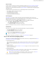
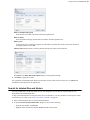
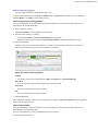
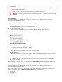
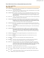
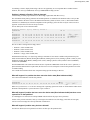
3. Scan selected volumes
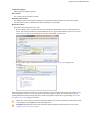
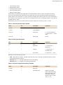
Figure 5: Scan in progress
During the scan:
•
•
To display or hide scanning events and progress details toggle More\Less Info button at any time.
To terminate the scan process, click Stop at any time. Results may be not accurate or complete.
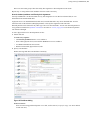
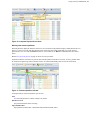
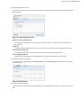
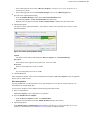
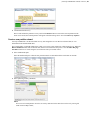
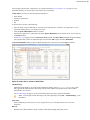
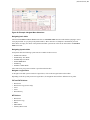
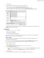
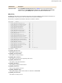
After the scan completes you will see scan results in the Volume scan result view.
A Logical Drive scan result appears in the Volume scan result view where results can be reviewed and files selected
for recovery.
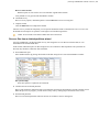
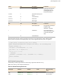
Figure 6: Volume scan result view
Note: We recommend you to save scan results to designated location for later use - you can use saved scan
results to save time on repeated scanning of same volume.
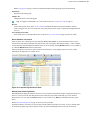
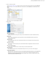
| Using Active@ UNDELETE | 16
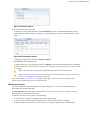
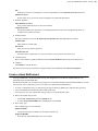
Work with logical drive scan results
Active@ UNDELETE is an advanced data recovery tool designed to recover data lost or deleted data, or even
information from formatted hard disks.
General description
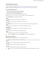
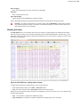
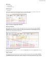
Logical drive (volume) scan results view displays all files detected after a logical drive scan.
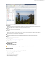
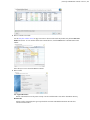
Figure 7: Volume scan result example
Drive Navigator
Show or hide left-sided navigation tree pane. To toggle this option use Layout > Drive Navigator menu from
view's toolbar.
Organize files
Use feature to group detected files by:
•
•
•
•
File extension;
Associated application;
Date (created, accessed and modified);
and more.
Read File Organizer on page 114 article for detailed information about grouping sets and customization.
File filter toolbar
This control is used to filter files in scan result. Read File filter toolbar control on page 38 for usage
information.
File preview
File preview is used to preview content and visually validate file before recovery File preview on page 36.
To make scan results easier to read, you may do the following:
•
•
•
To sort the list by a column in ascending order, click the column header.
To sort the list by the same column in descending order, click the column header a second time.
To show a list that is reduced in size by a filter, select one of the preset options in the File Filter toolbar.
| Using Active@ UNDELETE | 17
Search in folders
If volume contains too many files or location of required files is unknown use Search for deleted files and folders
on page 40 feature - more advanced way to find files by their attributes and name patterns then simple filtering
of contents of a scan. Search results will be shown in separate tabbed view and files can be recovered directly from
search result as well.
To initiate search select context folder or drive (to search through content of all volume) and either:
•
•
•
•
Select Action > Search command from main menu
Click Search button in view's toolbar
Use context menu Search command or
Use F3 keyboard shortcut for the same effect
Use File Organizer
File Organizer view on page 116 feature can be used to collect files from different sources (scans) in one
hierarchical collection and recovered in one batch applied the same recovering attributes for all selected file, like
naming convention or file attributes. To add file from scan result to File Organizer:
1. Select files in scan results using CTRL and SHIFT keyboard keys for multiple selection and
2. • Select Action > Add to File Organizer command from main menu
• Click Add to File Organizer button in view's toolbar or
• Use Add to File Organizer command from context menu
Repeat these commands if necessary for the same or for different file sources (scan results).
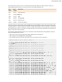
Use Disk Editor
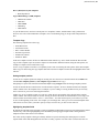
Files in this view can be edited in advanced hexadecimal Disk Editor. To open file in Disk Editor:
•
•
Click Open in Disk Editor button in view's toolbar or
Use Open in Disk Editor command in context menu
To view file record click Inspect File Record button in toolbar or use
Tip: It is recommended to save scan results for later use.
When you have found all files you looking for - proceed to Recover detected files on page 24.
Recover files from deleted (damaged) partitions
If lost files were on deleted or damaged partition, then procedure of file recovery is slightly different then Recover
files and folders from existing volume on page 12.
1. Scan disk (physical drive)
Apply scan directly on physical drive (disk), ignoring its logical structure in order to detect deleted (damaged)
partition. For exact scan procedure read: Scan for deleted partitions and files by their signatures on page 18
article.
2. Analyse scan results
A disk scan result appears in the Work with device scan results on page 19 view where results can be reviewed
and files selected for recovery.
3. Scan detected partitions
Detected partition can must be scanned in a same manner as existing volumes. Follow recommendations in
Recover files and folders from existing volume on page 12 article to continue.
Note: If files was detected already by their signatures no further steps are necessary - use Recover
detected files on page 24 procedure to recover detected files to the safe location.
4. Review results and recover detected files.
| Using Active@ UNDELETE | 18
Review in scan results group of files detected by their signatures or detected partition scan results.
Repeat steps 1-3 using different scan attributes for better results if necessary.
Scan for deleted partitions and files by their signatures
Active@ UNDELETE is an advanced data recovery tool designed to recover data lost or deleted data, or even
information from formatted hard disks.
A physical device is an installed hard disk, Flash card, external USB disk or any device that holds data. It can be
scanned in order to detect deleted (damaged) partitions or files by their signatures at the same time.
Detected partition can be scanned as any other logical drive for files and folders. You can scan detected partition to
verify partition content before partition restoration or to be able to recover (copy) files to safe location if partition
was deleted or damaged.
To scan a physical device for deleted partitions or files:
1. Initiate disk scan
From Recovery explorer:
• Click Restore partitions button in view's toolbar or
• Select a disk (physical device) item and click Scan button in view's toolbar or
• Use Scan command from context menu
• Double-click and disk (physical device) node
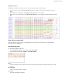
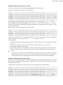
2. Specify scan attributes
Define scan range and other scan attributes if necessary.
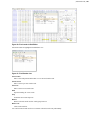
Figure 8: Disk Scan dialog
Scan area selector
Select scan area using predefined options: entire disk, unallocated only or specific range - use arrow markers
to mark scan area;
| Using Active@ UNDELETE | 19
Note: Scan area markers shown first and last sectors of scanning area. To enter exact start and end
sectors to scan click on sector label and enter exact value in text field;
Save Scan results
Enter path, where scan results will be saved as soon as scan completed;
Ignore Errors
Ignore disk Read/Write Errors;
Sectors to skip
Amount of sectors to skip in case of read errors. Use this attribute to avoid scan prolonging on massive bad
sectors arrays.
Detect partitions
Select desired File System of a partitions to be detected;
Detect files by their signatures
Select this option to specify exact file types to be detected during the scan. With this option, device scan reads
each disk sector trying to reconstruct any possible data related to unique file format.
Important: Turn this option off when you only want to detect and restore partition - it will
significantly save your scanning time.
Scan results filter
Define scan results refining filter by partition integrity status.
Multiple drive selection
Additional disks can be selected to scan on the Physical disks list to be scanned simultaneously. At least one
disk must be selected.
Apply the same settings to all selected devices
All scan options above, can be selected for each drive individually or, when this check box is selected, to be
the same for all selected logical drives.
Click Scan to initiate scan of selected disks.
3. Scan selected disks
During the scan:
•
•
To display or hide scanning events and progress details toggle More\Less Info button at any time.
To terminate the scan process, click Stop at any time. Results may be not accurate or complete.
After the scan completes you will see scan results in the Work with device scan results on page 19.
A Logical Drive scan result appears in the Device scan result view where results can be reviewed and files selected
for recovery.
Note: We recommend you to save scan results to designated location for later use - you can use saved scan
results to save time on repeated scanning of same volume.
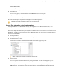
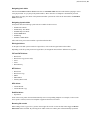
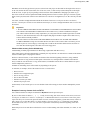
Work with device scan results
Active@ UNDELETE is an advanced data recovery tool designed to recover data lost or deleted data, or even
information from formatted hard disks.
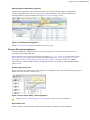
General description
Physical device scan view is used to review scan results, that includes partitions and files detected by signature, after
device scan made on data storage device.
| Using Active@ UNDELETE | 20
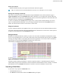
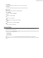
Figure 9: Interrupted Physical Device Scan
Device scan history
Show or hide device scan tree panel used for navigation of left side of a view. Use Layout > Device scan history
menu commands from view's toolbar to toggle this option.
Organize files
Use feature to group detected files by:
•
•
•
•
File extension;
Associated application;
Date (created, accessed and modified);
and more.
Read File Organizer on page 114 article for detailed information about grouping sets and customization.
Expand All
Expand all scan result groups
Collapse All
Collapse all items to scan result groups
Tip: It is highly recommended to save scan results for later use: Using scan results on page 33
Re-scan
Context data storage device (disk) can be rescanned with different attributes and scan boundaries. All new
results will appear in a same view under new scan result group for better results comparison and organization for
recovery.
Save and load scan results
Scan results can be saved individual for later use. Read Preserve scan results on page 34 article for details.
Device Partition view control
In Device Scan view, scanned devices represented by Device view control. For each selected scan, Device View
control shows scan progress indicator: blue stripe means scan is incomplete and solid green stripe - scan is complete
for selected range. All interrupted (incomplete) scans can be resumed by clicking Resume button in view's toolbar or
by command Resume Scan in item context menu.
If detected partition is selected, its relative position and scanned size is also displayed on Device View Control
indicating is this partition is recoverable or not.
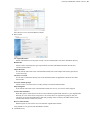
| Using Active@ UNDELETE | 21
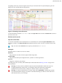
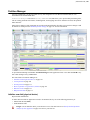
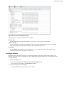
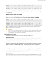
Figure 10: Complete Physical Device Scan
Working with detected partitions
Detected partitions displayed with their status to be recovered and overall partition integrity. When partition Recover
Status is "Can be recovered" then this partition can be restored as part of disk partitioning. To restore detected
partition select it in view and click Restore button in view's toolbar or use Restore command from item's context
menu.
Read Restore detected partition on page 32 article for exact procedure.
If partition cannot be restored by any reason, data from this partition still can be recovered. To do so, partition must
be scanned (as regular Logic Drive) and files needs to be selected individually and recovered to safe location.
Figure 11: Detected partition indicator
For deeper analysis of detected partition you can also:
Scan
Scan detected partition to evaluate validity if its content.
Edit boot records
Edit partition attributes before restoring.
Open in Disk Editor
Open partition in Disk Editor - advanced hexadecimal build-in disk editor.
| Using Active@ UNDELETE | 22
Working with files detected by signatures
Files detected by signatures are shown under related disk scan item and combined in groups by signature type
(default). Original file names can not be recovered due to feature limitations, however they can generated in
meaningful pattern by using file attribute meta tags in File Organizer on page 114 tool.
Figure 12: File Detected by signatures
Read Recover detected files on page 24 article for exact recovery steps.
Recover files by their signatures
Active@ UNDELETE is an advanced data recovery tool designed to recover data lost or deleted data, or even
information from formatted hard disks.
Files on hard drive can be detected by their unique file signatures. Active@ UNDELETE can detect these files (see
Supported file signatures on page 51 for exact list of file types) during Scan a volume (logical drive) for deleted
files on page 13 or Scan for deleted partitions and files by their signatures on page 18. In first case, scanning
will be limited by volume boundaries when by scanning physical disk, you can specify custom boundaries of disk
surface to scan.
Volume (logical drive) scan
During volume of scan you have to select file signatures on scan dialog and they will be detected (if any) among other
deleted or live files on selected volume(s) only.
Figure 13: Scan volume dialog - add file signatures
Note: See Scan a volume (logical drive) for deleted files on page 13 for more information.
Physical disk scan
Files by signatures can be also detected during scan of disk surface not limited by volume boundaries.
| Using Active@ UNDELETE | 23
Figure 14: Scan disk dialog - add file signatures
Note: See Scan for deleted partitions and files by their signatures on page 18 for more information.
Evaluate scan results
Detected files (if any) are shown in scan result view grouped in special virtual folder named Files by Signatures. Due
to particular qualities of this algorithm, it is impossible to recover original file names, date and other attributes. To
evaluate integrity of some of the detected files you can use File preview on page 36 feature.
Note: Amount of selected files signatures directly impacts on total scan time.
Recover detected flies
Files, detected by their signatures can be recovered in a same manner as other detected files. The main differences
only - file names. Due to nature of detection algorithm all names for that files generated during the scan and original
names can not be discovered. You can use File Organizer on page 114 feature to assign meaningful names for
these files using internal file attributes (meta tags) or simple renaming patterns.
Read Recover detected files on page 24 article for exact recovery procedure.
Working with a corrupted RAID
Active@ UNDELETE is an advanced data recovery toolset allows to reconstruct damaged or broken RAIDS.
If you have a corrupted RAID configuration and one or more drives in the array are damaged, you can combine the
healthy drives together with the damaged drives in a virtual disk array (Virtual RAID). If the damaged drives are
inaccessible, you can substitute a "dummy" drive as a replacement. Active@ UNDELETE simulates the RAID
assembly and you can scan this virtual array as a logical device.
To get access to the files on damaged raid and recover them follow:
1. Create virtual RAID
| Using Active@ UNDELETE | 24
Use Virtual RAID Assembly on page 63 procedure to create virtual array. You can create unlimited number of
arrays with different attributes and disk combinations for better access.
2. Recover files from RAID assembly
After Virtual RAID is created you can use one of the methods below to retrieve files from assembled RAID to
safe location:
•
•
•
Recover files and folders from existing volume on page 12
Recover files from deleted (damaged) partitions on page 17
Recover files by their signatures on page 22
Recover detected files
You may recover damaged or deleted files and folders directly from the Recovery Explorer view on page 8, Work
with logical drive scan results on page 16, Work with device scan results on page 19 and Search for deleted
files and folders on page 40. Recovering deleted files and folders is one of the essential features of Active@
UNDELETE.
1. Select files in a view
Select files in any view mentioned above using cursor selection (Use Shift or Ctrl keys for mutli-selection).
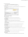
2. Open File and Folder recovery dialog
After files are selected in a view, click Recover button in view's toolbar or use Recover command from context
menu or use Ctrl+R shortcut.
3. Confirm recovery location and attributes
By default File recovery dialog appears in simplified form - in most of the cases default recovery settings are
sufficient for file recovery. However, to use advanced options click More Recovery Options button.
Figure 15: File Recovery dialog - simplified
Enter destination path where file will be recovered and click Recover button.
Figure 16: File recovery dialog - extended
| Using Active@ UNDELETE | 25
Use original file names
Names of detected files will be preserved only if no file with the same name already exists in the destination
directory.
Rename files
All files will be renamed by their given specified file root name and added enumeration ID. File extensions
remain intact.
Unique file name
If a file with the same name exists in the destination folder, a file with a unique name will be generated to
avoid overwriting.
Ask before overwrite
If a file with the same name already exists in the destination folder, the application will ask the user for a
specific action to take.
Overwrite without prompt
All files will be overwritten in the event if they already exist in the destination folder.
Skip existing files
If a file with the same name exists in the destination folder, recovery of a new file will be skipped.
Create Folder Structure
When this option is selected files will be recovered with their original folder structures e.g. original folder
hierarchy as it was on the storage source. In case files were organized in groups (date, file extensions, or by
an associated application) then such groupings will be created by the folder structure in the location where the
files will be recovered to.
Recover Name Streams
With this option on, files will be recovered with their original name streams.
Browse destination folder
Opens the destination folder in the default OS file browser.
Detailed Log
With this option on, the log file contains more detailed information about recovered files.
Use Disk Lock
The source disk will be locked during the file recovery process. It will be unlocked as soon as the process is
completed.
Ignore Disk Lock Errors
With this option on, the file recovery process will continue even if locking of the source device fails.
Ignore Write Errors
No error messages will appear and all write errors will be ignored during the recovery process.
Ignore Read Errors
No error messages will appear and all read errors will be ignored during the recovery process.
Click Recover button to begin file recovery.
4. Observe recovery process
Observe recovery process and verify recovered files in destination folder. Repeat recovery process if necessary.
If files were recovered successfully they will appear in destination folder. Repeat steps 1-3 if necessary.
Decrypt recovered files
Active@ UNDELETE is an advanced data recovery tool designed to recover data lost or deleted data, or even
information from formatted hard disks.
During the recovery of encrypted files to any destination that doesn’t support encryption, Active@ UNDELETE
creates temporary (*.EFS) files. These files can be decrypted later at any time by using the File Decryption Tool.
| Using Active@ UNDELETE | 26
1. Open the Decrypt Files dialog
• Use the command tools and select Decrypt Files from the main menu.
• From the Tools tab in the command bar, choose the Decrypt Files command.
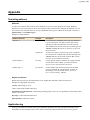
2. Add files to decrypt
Add temporary recovered encrypted files (*.efs) or open the Decrypted Files log (*.txt) created during recovery by
using the Add button.
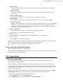
Figure 17: Decrypt files dialog box
Delete temporary files
All temporary recovered encrypted source files will be deleted after decryption.
Browse Destination
The folder where files will be decrypted will be opened by the default OS files browser.
Create Detailed Log
The log files will contain more detailed information about the forthcoming process.
Use Disk Lock
The source disk will be locked during the file recovery process. The disk will be unlocked as soon as the
process is completed.
Ignore Disk Lock Errors
With this option on, the file recovery process will continue even if locking of the source device fails.
Ignore Write Errors
No error messages will appear and all write errors will be ignored during the recovery process.
Ignore Read Errors
No error messages will appear and all read errors will be ignored during the recovery process.
Generate unique file name
If a file with the same name exists in the destination folder, then a file with a unique name will be generated to
avoid overwriting.
Ask before overwrite
If a file with a certain name already exists in the destination folder, the application will ask the user for a
specific action to take.
Overwrite without prompt
All files will be overwritten even if they already exist in the destination folder.
Skip existing files
If a file with the same name already exists in the destination folder, recovery of that file will be skipped.
| Using Active@ UNDELETE | 27
3. Decrypt selected files
Set other options if necessary and then click the Decrypt button to complete the task.
When process completes decrypted files will appear in destination folder.
Restore partitions
Active@ UNDELETE is an advanced data recovery tool designed to recover data lost or deleted data, or even
information from formatted hard disks.
If you cannot see partitions on your device, or if you know that partitions are missing, you may first scan a device to
find partitions. Restoring a deleted or damaged partition can be done in three stages:
1. Scan disk
Scan a physical device individually or several at once for a deleted or damaged partitions. Usually, only
unallocated space needs to be scanned.
For details about scanning read: Scan for deleted partitions and files by their signatures on page 18.
2. Evaluate scan results
Review scan results and analyse detected partition integrity (restoration status) and validity. Use partition filter
and preliminary partition scan to examine detected partitions before restoration.
For details read: Work with device scan results on page 19
3. Restore partition
Restore deleted partition at previous location.
For detailed reference read: Restore detected partition on page 32
Scan for deleted partitions and files by their signatures
Active@ UNDELETE is an advanced data recovery tool designed to recover data lost or deleted data, or even
information from formatted hard disks.
A physical device is an installed hard disk, Flash card, external USB disk or any device that holds data. It can be
scanned in order to detect deleted (damaged) partitions or files by their signatures at the same time.
Detected partition can be scanned as any other logical drive for files and folders. You can scan detected partition to
verify partition content before partition restoration or to be able to recover (copy) files to safe location if partition
was deleted or damaged.
To scan a physical device for deleted partitions or files:
1. Initiate disk scan
From Recovery explorer:
• Click Restore partitions button in view's toolbar or
• Select a disk (physical device) item and click Scan button in view's toolbar or
• Use Scan command from context menu
• Double-click and disk (physical device) node
2. Specify scan attributes
Define scan range and other scan attributes if necessary.
| Using Active@ UNDELETE | 28
Figure 18: Disk Scan dialog
Scan area selector
Select scan area using predefined options: entire disk, unallocated only or specific range - use arrow markers
to mark scan area;
Note: Scan area markers shown first and last sectors of scanning area. To enter exact start and end
sectors to scan click on sector label and enter exact value in text field;
Save Scan results
Enter path, where scan results will be saved as soon as scan completed;
Ignore Errors
Ignore disk Read/Write Errors;
Sectors to skip
Amount of sectors to skip in case of read errors. Use this attribute to avoid scan prolonging on massive bad
sectors arrays.
Detect partitions
Select desired File System of a partitions to be detected;
Detect files by their signatures
Select this option to specify exact file types to be detected during the scan. With this option, device scan reads
each disk sector trying to reconstruct any possible data related to unique file format.
Important: Turn this option off when you only want to detect and restore partition - it will
significantly save your scanning time.
Scan results filter
Define scan results refining filter by partition integrity status.
| Using Active@ UNDELETE | 29
Multiple drive selection
Additional disks can be selected to scan on the Physical disks list to be scanned simultaneously. At least one
disk must be selected.
Apply the same settings to all selected devices
All scan options above, can be selected for each drive individually or, when this check box is selected, to be
the same for all selected logical drives.
Click Scan to initiate scan of selected disks.
3. Scan selected disks
During the scan:
•
•
To display or hide scanning events and progress details toggle More\Less Info button at any time.
To terminate the scan process, click Stop at any time. Results may be not accurate or complete.
After the scan completes you will see scan results in the Work with device scan results on page 19.
A Logical Drive scan result appears in the Device scan result view where results can be reviewed and files selected
for recovery.
Note: We recommend you to save scan results to designated location for later use - you can use saved scan
results to save time on repeated scanning of same volume.
Work with device scan results
Active@ UNDELETE is an advanced data recovery tool designed to recover data lost or deleted data, or even
information from formatted hard disks.
General description
Physical device scan view is used to review scan results, that includes partitions and files detected by signature, after
device scan made on data storage device.
Figure 19: Interrupted Physical Device Scan
Device scan history
Show or hide device scan tree panel used for navigation of left side of a view. Use Layout > Device scan history
menu commands from view's toolbar to toggle this option.
Organize files
Use feature to group detected files by:
•
•
•
•
File extension;
Associated application;
Date (created, accessed and modified);
and more.
| Using Active@ UNDELETE | 30
Read File Organizer on page 114 article for detailed information about grouping sets and customization.
Expand All
Expand all scan result groups
Collapse All
Collapse all items to scan result groups
Tip: It is highly recommended to save scan results for later use: Using scan results on page 33
Re-scan
Context data storage device (disk) can be rescanned with different attributes and scan boundaries. All new
results will appear in a same view under new scan result group for better results comparison and organization for
recovery.
Save and load scan results
Scan results can be saved individual for later use. Read Preserve scan results on page 34 article for details.
Device Partition view control
In Device Scan view, scanned devices represented by Device view control. For each selected scan, Device View
control shows scan progress indicator: blue stripe means scan is incomplete and solid green stripe - scan is complete
for selected range. All interrupted (incomplete) scans can be resumed by clicking Resume button in view's toolbar or
by command Resume Scan in item context menu.
If detected partition is selected, its relative position and scanned size is also displayed on Device View Control
indicating is this partition is recoverable or not.
Figure 20: Complete Physical Device Scan
Working with detected partitions
Detected partitions displayed with their status to be recovered and overall partition integrity. When partition Recover
Status is "Can be recovered" then this partition can be restored as part of disk partitioning. To restore detected
partition select it in view and click Restore button in view's toolbar or use Restore command from item's context
menu.
Read Restore detected partition on page 32 article for exact procedure.
If partition cannot be restored by any reason, data from this partition still can be recovered. To do so, partition must
be scanned (as regular Logic Drive) and files needs to be selected individually and recovered to safe location.
| Using Active@ UNDELETE | 31
Figure 21: Detected partition indicator
For deeper analysis of detected partition you can also:
Scan
Scan detected partition to evaluate validity if its content.
Edit boot records
Edit partition attributes before restoring.
Open in Disk Editor
Open partition in Disk Editor - advanced hexadecimal build-in disk editor.
Working with files detected by signatures
Files detected by signatures are shown under related disk scan item and combined in groups by signature type
(default). Original file names can not be recovered due to feature limitations, however they can generated in
meaningful pattern by using file attribute meta tags in File Organizer on page 114 tool.
Figure 22: File Detected by signatures
Read Recover detected files on page 24 article for exact recovery steps.
Edit the boot sector template in detected partition
Active@ UNDELETE is an advanced data recovery tool designed to recover data lost or deleted data, or even
information from formatted hard disks.
It may be necessary for you to edit detected partition attributes directly when some attributes are detected incorrectly
or need adjustments.
| Using Active@ UNDELETE | 32
Any detected partition can be cloned (virtually copied) before manually altering partition attributes and properties.
We recommend that you edit the clone rather than directly edit the original partition. Any detected partition can be
cloned as any times as you want.
To edit detected partition:
1. Select detected partition
Select a detected partition in the scan results tree.
2. Open Edit Boot Sector Template dialog box
• From the view toolbar click Edit Boot Records button
• Right-click the selected partition and click Edit Boot Records... from the context menu.
3. Edit partition attributes
Change partition attributes as needed. Read Edit boot sectors on page 112 article for details.
Restore detected partition
Active@ UNDELETE is an advanced data recovery tool designed to recover data lost or deleted data, or even
information from formatted hard disks.
We recommend that you restore a partition with a certainty status of Acceptable or higher.
Before you restore a partition, you may clone or edit the partition directly to adjust its properties.
Here are some rules to follow when restoring a partition:
Assigning a drive letter
•
•
•
Be aware of the location of executable files or files required by the operating system. Many MS-DOS and
Windows programs refer to a specific drive letter when describing a path to executable files.
Drives A: and B: are usually reserved for floppy disk drives, but you can assign these letters to removable drives if
the computer does not have a floppy disk drive.
Hard disk drives in the computer receive letters C through Z, while mapped network drives are assigned drive
letters in reverse order (Z through B).
Setting the partition as active
•
•
•
•
•
•
•
•
•
You may set only a primary partition as active. You cannot set a logical drive (an extended partition) as active.
To set a partition as active, the partition must have an MBR (Master Boot Record) as the first sector.
A computer can only have one active partition per disk.
The name commonly used for the partition that contains the start-up files is the boot partition. The name
commonly used for the partition that contains the operating system files is the system partition.
The system partition can never be part of a striped volume, spanned volume, or RAID-5 volume.
The system partition must be a primary partition that has been marked as active for start-up purposes. It must be
located on the disk that the computer accesses when starting up the system.
There can be only one active system partition on a disk at a time.
You may have multiple basic disks and each disk can have one active partition. However, the computer will only
start from one specific disk. If you want to use another operating system, you must first mark its system partition
as active before restarting the computer.
You cannot mark an existing dynamic volume as active. However, you can convert a basic disk containing the
active partition to a dynamic disk. After the disk is converted, the partition becomes a simple volume that is active.
If the active partition is not the current system or boot partition it becomes a simple volume and loses its entry in
the partition table. Therefore it can no longer be active.
Extended partition
•
A computer can only have one extended partition per physical disk device.
| Using Active@ UNDELETE | 33
•
You cannot create an extended partition on a disk if it already has four primary partitions.
Restore partition
1. Select partition to restore
Select a detected partition in the Work with device scan results on page 19. Consider partition recovery status
and overlapping with existing once.
2. Initiate partition restore
To open the Restore Partition dialog, do one of the following:
•
•
From the toolbar click the Restore Partition button or use the command action Restore Partition from the
main menu.
Right-click the selected item and click the Restore Partition command from the context menu.
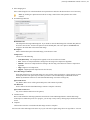
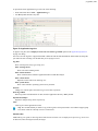
Figure 23: Restore partition dialog
Assign Drive Letter
To assign a drive letter to the recovered partition, select a letter from the drop-down list.
Make restored partition Active
To set this partition as active, check the Make restored partition Active check box.
Create Extended Partition
Before a partition is restored, unallocated space can be set as an extended partition by checking the Create
Extended Partition check box.
3. Click Restore button
If partition restore successfully it should become accessible for default OS file explorer.
Using scan results
Active@ UNDELETE is an advanced data recovery tool designed to recover data lost or deleted data, or even
information from formatted hard disks.
Scan results of physical disks (storages) or logical drives (volumes) are shown in dedicated tabbed views, that has
advanced tools to analyse, sort and organize the results and preserve (save) them for later use.
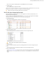
After you have completed a device scan, a Scan Results branch appears in the Recovery Explorer tree. Detected
partitions are listed in order of their certainty of recovery.
| Using Active@ UNDELETE | 34
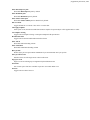
There are 12 attributes that define a partition. In some cases, the application cannot be certain that the found item
actually is a partition. The rating in the order of certainty depends on how many attributes are found and what
condition they are in. You may perform the following actions on partitions in the Scan Results branch:
•
•
•
Stop and resume interrupted scan on page 35
Filter detected partitions by certainty on page 39
Save and Load scan results
Preserve scan results
Active@ UNDELETE is an advanced data recovery tool designed to recover data lost or deleted data, or even
information from formatted hard disks.
It can take a long time to run a default disk scan or a low level disk scan. Because you are dealing with a large volume
of information, you might not be able to review all the data in one session.
So that you do not have to scan a volume or physical disk again, you can save and re-use valuable scan results.
You can save Scan Results branch or make a separate save for each disk scan or save all scans set for a particular
device.
Scan results are saved with the file extension .scaninfo.
Warning: Save a scan results file to a physical drive that is different from the drive that was scanned.
Remember: Due to continuous activity on disk (volume) data saved in scan results become none
synchronous with actual information on disk and become obsolete. Using old saved scan results may lead to
unpredicted behaviour.
Preserving and using scan results for volumes and physical disks is slightly different.
Volume scan results
Physical disk scan results
Save Scan Results
1. To save the entire Scan Results branch, select the branch.
2. To save a device node, select it under Scan Results.
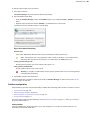
3. Right-click the selected node and click Save Scan Result from the context menu. The Save Scan Result dialog
appears with the default path and a suggested file name.
4. To change the file path, browse to a different folder.
5. To change the file name, enter a name in the file name field.
6. Click Save.
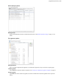
Load Scan Results
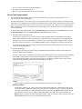
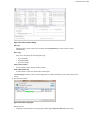
1. To open the Load Scan Results dialog, do one of the following:
| Using Active@ UNDELETE | 35
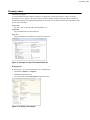
From the File menu, click Open > Scan Result…
Right-click the logical drive node and click Load Scan Result from the context menu.
If there is a Scan Results branch in the Recovery Explorer tree, right-click the Scan Results branch or rightclick a Scan Results node and click Load Scan Result from the context menu.
2. Browse to the folder that contains the scan result file and select the file.
3. Click Open.
•
•
•
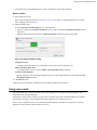
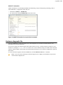
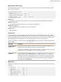
Figure 24: Load scan shortcuts on Welcome View
The data from the scan results file appears in a Scan Results node in the Recovery Explorer tree.
Note: Loading scan results feature is not available in Active@ UNDELETE Freeware or Standard
edition. Please visit http://www.active-undelete.com to read more about Active@ UNDELETE Professional
and Ultimate editions
Remove Scan Results
Data in the Scan Results branch is copied from the original physical device. You may remove any node – including
detected partitions - from the Scan Results branch without harming the data on the original physical device.
To remove scan results:
1. To remove the entire Scan Results branch, select the branch.
2. To remove a device node, select it under Scan Results.
3. Right-click the selected node and click Remove Scan Result from the context menu.
The selected node is removed from the Recovery Explorer tree.
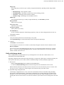
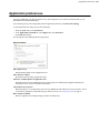
Stop and resume interrupted scan
Active@ UNDELETE is an advanced data recovery tool designed to recover data lost or deleted data, or even
information from formatted hard disks.
To stop a physical device scan at any time, press Stop. After you stop a scan, a Scan Results branch appears in the
Recovery Explorer tree.
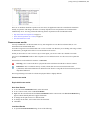
The example above shows how incomplete scan results are indicated. An icon appears next to each node in the Scan
Results branch.
Incomplete Device Scan
An incomplete (interrupted) device scan can be resumed at any time.
| Using Active@ UNDELETE | 36
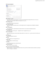
To resume a terminated scan:
1. Select a device scan result under the Scan Results branch.
2. To resume the scan, do one of the following:
•
•
From the toolbar, click the Resume Scan button.
Right-click the selected device scan and click Resume Scan from the context menu.
Completed Device Scan
A completed device scan cannot be resumed.
File preview
Active@ UNDELETE is an advanced data recovery tool designed to recover data lost or deleted data, or even
information from formatted hard disks.
File Preview allows you to view the contents of an image file (jpg, bmp, gif, png etc.) or document before you
recover the file.
To open the File Preview panel from any view, do one of the following:
•
•
•
Double-click an image file.
Right-click an image file and click File Preview from the context menu.
Select an image file and click File Preview from the main toolbar.
| Using Active@ UNDELETE | 37
Preview mode
Default preview mode can be selected either as Hexadecimal or Rendered, in which case file will be shown as an
image (for graphics files) or rendered by one of the registered file previewers.
Font size
Select size of the font for hexadecimal mode;
Auto-follow
With this option on files, selected in context source, will be previewed automatically. Toggle this option off if for
any reason file preview causes delays in file navigation.
Info
In this mode, all registered previewers and supported graphics formats in current system will be shown.
Recover
Recover previewed file to safe location.
Add to File Organizer
Add previewed file to File Organizer on page 114 tool.
Inspect file record
Inspect file record in Disk Editor.
Open in Disk Editor
Edit selected file in Disk Editor.
Note: If the preview file is not an image file, it appears in hexadecimal and text mode.
Supported file types
By default, File preview can preview contents of following file types:
•
•
•
•
•
Microsoft Windows bitmap image file [.bmp];
GIF File Format [.gif]
ICO File Format[.ico]
JPEG File Interchange Format [.jpeg]
JPG File Interchange Format[.jpg]
| Using Active@ UNDELETE | 38
•
•
•
•
•
•
•
•
•
Multiple-image Network Graphics [.mng]
Portable Bitmap Utilities File Format [.pbm, .pgm]
Portable Network Graphics File Format [.png]
Netpbm color image format [.ppm]
Scalable Vector Graphics File [.svg, .svgz]
Truevision TGA File Format [.tga]
Tagged Image File Format [.tif, .tiff]
Monochrome bitmap forma [.xbm]
X Window System image [.xpm]
In windows OS, if registered document previewers are available, File Preview use OS-integrated file preview engines
and allows to preview files such as MS Office Documents, RTF texts, PDF document or even small media files.
Supported file types for preview are vary for each operating system. Use Info toolbar's toggle to show all registered
File Previewers.
File filter toolbar control
Active@ UNDELETE is an advanced data recovery tool designed to recover data lost or deleted data, or even
information from formatted hard disks.
The File Filter toolbar is used to organize files in related control - file list or file browser.
Case sensitive
Consider case in file filtering
Hide Empty Folders
Hides folders, if their has no filtered files.
By default, the results of a scan contain all files and folders. Use commands in the File filter toolbar to make a large
list of files smaller and easier to read.
File Filter Toolbar is used in the following views:
•
•
•
•
Recovery Explorer view on page 8
Work with logical drive scan results on page 16
Search results view on page 42
File Organizer view on page 116
The filtered result may be applicable over an entire list (for example in Search results view on page 42) of within
a selected folder (for example in Recovery Explorer view on page 8).
Using File Filter Toolbar
Enter filter pattern in text field and press ENTER key on keyboard pr click Apply Filter button in toolbar. File filter
toolbar accepts wildards in filter patterns. Toolbar also remembers the user's search history so the user can easily
repeat his search at any time.
For example, if you want to find PNG files on the specific drive you will need to select that drive and type *.png in
the toolbar and click on Apply Filter button.
Use semi-column to apply multiple filter criteria, for example: to filter in only PNG and JPG files type in toolbar
*.png;*.jpg and press either ENTER or click on the Apply Filter on the right side of the toolbar.
•
•
•
•
To display an unfiltered list, click Show All Files and Folders button.
To display only existing files and folders, click Show only existing Files and Folders button.
To display only deleted files and folders, click Show only deleted Files and Folders button.
To further reduce the size of a list, enter a pattern in File Filter field and press ENTER key on keyboard. The list
displays only those files that match the pattern.
| Using Active@ UNDELETE | 39
Wildcards
A wildcard is a character that can be used as a substitute for any of a class of characters in a search. Wildcard
characters are often used in place of one or more characters when you do not know what the real character is or you
do not want to enter the entire name. In Active@ UNDELETE three types of wildcard are used: star or asterisk(*),
question mark (?) and number sign (#).
Examples of using wildcards:
Wildcard character
Example
Description
Asterisk (*)
docum*
Use the asterisk as a substitute for zero or more characters
if you are looking for a file that you know what it starts
with and you cannot remember the rest of the file name.
The example locates all files of any file type that begin with
"docum" including documents.txt, document_01.doc and
documentum.doc.
docum*.doc
To narrow the search to a specific type of file, include the
file extension. The example locates all files that begin with
"docum" and have the file name extension .doc, such as
document_01.doc and documentum.doc.
Question mark (?)
doc?.doc
Use the question mark as a substitute for a single character
in a file name. In the example, you will locate the file
docs.doc or doc1.doc but not documents.doc.
Number sign (#)
doc_###.doc
Use the number sign (also known as the pound or hash
sign) as a substitute for a single number in a name. In
the example, you will locate the file doc_012.doc or
doc_211.doc but not doc_ABS.doc.
Filter detected partitions by certainty
Active@ UNDELETE is an advanced data recovery tool designed to recover data lost or deleted data, or even
information from formatted hard disks.
After you complete a scan, detected partitions are listed in order of their certainty status based on attributes and
validation level. To make a long list of partitions easier to read, remove partitions with a status of Bad and lower
using a filter. To filter detected partitions:
1. Select scan result
In the Device scan results view select a scan result node with detected partitions.
2. Open the Filter Detected Partition dialog:
• From the toolbar, click Partition Filter.
• Right-click the partition and click Partition Filter from the context menu.
3. Set filter values
| Using Active@ UNDELETE | 40
Filter by Partition File System
Select the file system that will remain in the filtered partition list.
Filter by Status
Select the partition integrity statuses that will remain in the filtered partition list.
Filter by Size
To restrict the size of a partition to display, click the Filter by Partition Size check box and enter the lowest
and highest partition size in MB.
Advanced tab filtering will let you filter a partition with specific NTFS or FAT attributes.
Press Reset in the Filter Detected Partition dialog to cancel partition filtering.
4. Click Filter to apply filter criteria
List of partitions with attributes that matches selected filter criteria will be shown in result view. Use Reset filter
command to return partition list to original state.
Search for deleted files and folders
Active@ UNDELETE is an advanced data recovery tool designed to recover data lost or deleted data, or even
information from formatted hard disks.
To help you find deleted files in a long list of files from a scanned drive, you may search the list with specific search
criteria and review results in a Search for deleted files and folders on page 40.
1. Select a scanned logical drive or scanned detected partition
2. To open the Search for Files and Folders dialog box, do one of the following:
•
•
From the main toolbar, click Search.
Right-click the selected item and click Search from the context menu.
| Using Active@ UNDELETE | 41
3. Provide general search criteria
Enter search criteria in Look for and other search options (if required) and click Search button to start searching in
selected location.
Figure 25: General Search Options
Recursive search in subdirectories
Use this option to search the root level of the drive and all sub folders. To search only the root folder, clear
this check box.
Match case
To display files that match upper and lower case letters in the Look for field, select the Match case check box.
Search among existing only
To display only files that are not deleted, select the Search among existing only check box.
Search among deleted only
To display only files that are deleted or damaged, select the Search among deleted only check box.
4. Set date search criteria [optional]
To display files by a specified date, in the Date Criteria tab, in the Date Type drop-down list, choose a type and
select a date range.
Figure 26: Date Criteria
5. Set file size criteria [optional]
To display files by a specified file size, in the Size tab, select Small, Medium or Large, or specify the size range in
KB.
| Using Active@ UNDELETE | 42
Figure 27: File Size Criteria
6. Set file attributes criteria [optional]
To display files based on file attributes in, the File Attributes tab select file attributes that should be present
(Include Files and Folders Attributes) or otherwise exempt (Exclude Files or Folders with Attributes) in search
result.
Figure 28: File Attributes Criteria
To change all settings back to defaults, click Restore Defaults.
7. Click Search to start searching process
To display disk image events and progress details, click Details. To terminate the searching process, click Stop
at any time. In this case search results may be not accurate or complete. After the search is done, a Search Results
view appears.
Note: You may repeat a search many times and refine the search criteria for better results.
Note: See Searching patterns on page 126 for details how to set search criteria. You may use File filter
toolbar control on page 38 to improve search results.
After search complete, Search results view on page 42 must appear with search results (if any for provided
criteria). You can repeat steps form 1 to 4 for desired effect.
Search results view
Active@ UNDELETE is an advanced data recovery tool designed to recover data lost or deleted data, or even
information from formatted hard disks.
The Search Results view appears after you perform a Search for deleted files and folders on page 40. The top
panel displays the results of the search in a list.
To make this list easier to read, you may do the following:
•
•
•
To sort the list by a column in ascending order, click the column header.
To sort the list by the same column in descending order, click the column header a second time.
To show a list that is reduced in size by a filter, select one of the preset options in the File Filter toolbar.
| Using Active@ UNDELETE | 43
To recover an item in this list, right-click the item and choose Recover from the context menu or click Recover
button in toolbar.
To preview an item, select it and click File Preview.
To change search criteria and repeat the search at the same location, click Search Again.
Note: You can create a custom filter for this list. For more information see File filter toolbar control on page
38.
Note: For information about how to start a search, see Search for deleted files and folders on page 40
File signatures
Introduction
Active@ UNDELETE comes with more than fifty predefined (internally programmed, very fast) file signatures to be
used to detect particular files (MS Office Documents, many Image formats, ZIP archives, MP3, etc. during disk scan.
However sometimes advanced users need to detect more specific file formats, not being defined in default signatures
set. For that purpose - custom file signature can be defined by defining file beginning and file length criteria. See
Custom (user defined) file signature templates on page 43 article for details.
Custom (user defined) file signature templates
Active@ UNDELETE is an advanced data recovery tool designed to recover data lost or deleted data, or even
information from formatted hard disks.
Active@ UNDELETE offers advanced tools to define user's templates for signatures to be analyzed. Signatures can
be defined using extended definition language RegExp (Regular Expressions).
To define custom signature template:
1. Open Preferences dialog
Click Tools > Preferences command to open Preferences dialog
2. Add new custom signature
•
•
Click Add button to define new custom file signature.
Click Import button to load (import) custom file signature from script file (*.ini format). See Custom file
signature size script on page 46 for details.
| Using Active@ UNDELETE | 44
Figure 29: Supported file signatures
Note: You can edit your custom file signature template at any time by selecting your template in list and
clicking Edit button or simply double-clicking on template's name.
3. Edit file signature template
Use Edit file signature template on page 44 dialog to define starting signature criteria ans file length (file end)
criteria of signature template.
Edit file signature template
Provide template name and brief description - for future references. Specify file extension of a file type you defining
(optional). To completely define custom file signature template you need to enter Header (beginning of the file) and
Footer (end of the file) criteria using RegExp syntax. Header criteria could be more then one and all of them must be
met to consider beginning of the file. Footer's criteria could more then one too, but at least one of them must be met to
consider end of file.
Template name
Unique template name.
| Using Active@ UNDELETE | 45
Template description
Brief template description (optional)
File extension
File extension for this template (optional)
Beginning of File Criteria
List of RegEx criteria, considered as beginning of file combined as AND statements. Not earlier then and Not
later then specifies limits of defined criteria in the beginning of a file template.
End of File Criteria
End of files can be determined in two ways:
•
By list of RegEx criteria, considered as end of file combined as OR statements. In case of missing file footer
criteria, end of file will be taken by defined Maximum file size. Append after attribute specifies size of end of
a file. File size is used in case of missing file end criteria. By default its 65535 bytes.
•
By using simple script to calculate end of file. See Custom file signature size script on page 46 for
reference.
Defined custom file signatures templates are stored in INI files in user's selected locations and will be loaded at every
consequent application starts. You can also import such custom signature template files created by other users by
clicking Import button and specifying full path to custom file signatures template file in opened dialog. See Custom
file signature size script on page 46 for details.
Note: Also you can specify Custom File signature template from Volume (logical Drive) Scan dialog or Disk
Scan dialog by clicking Add button near file signatures list.
Important: Regular Expressions can be used while defining signature headers and footers. Please check
RegExp syntax on a web for examples .
| Using Active@ UNDELETE | 46
Custom file signature size script
Custom signatures file size calculation syntax.
Custom (User Defined) File Signatures are saved in text file and can be edited by using simple text editor (like
notepad) or by using Active@ UNDELETE tool: Custom (user defined) file signature templates on page 43.
User defined template reference
•
•
•
Empty lines and lines starting with semicolon are ignored
Sections order and lines order in sections are not important
Letter case is not important (except RegExp fields)
Section TEMPLATES - required and contains fields numbering from one;
TEMPLATE### - points to the section where signature template is described (numbered from one).
Section Template Header - required and contains fields:
BEGIN
required. Points to the section describing begin of the signature file
FOOTER
non required. Points to the section describing end of the signature file
MAX_SIZE
non required. Maximum file size to force file-end, if no file-end signature is detected. By default it is 64Kb
GROUP
non required. If missed - template goes to User Defined templates group by default
DESCRIPTION
non required. This is a descriptive name of user template being displayed on a screen
EXTENSION
non required. This is a file extension to be assigned and displayed
SCRIPT
non required. Refers to the section where size of the file being calculated
Note: If field SCRIPT is present, then field FOOTER is ignored in template header section.
Beginning of the file section
Section describing file beginning (required), contains fields of the same type:
<signature> = <offset_start> | <offset_end>
signature
expression (regular or Reg Exp-compatible). Expression max length is 1024 bytes
offset_start
acceptable minimal signature offset from the beginning of the file
offset_end
acceptable maximum signature offset from the beginning of the file
Note: If there are several fields listed in signature beginning, logical AND operation applied to confirm file
start.
| Using Active@ UNDELETE | 47
End of file section
Section describing file end (not required), contains fields of the same type:
<signature> [= <bytes_to_append>]
signature
expression (regular or RegExp-compatible). Expression max length is 1024 bytes
bytes_to_append
not required. How many bytes to append to the file after the signature is found
Note: If there are several fields listed in signature, logical OR operation applied to define file end.
File size calculation script
Section calculating file size (not required), contains operators of four types:
<result> = <command> (<argument>, <argument>)
<result> = <argument>
IF (<argument> <condition> <argument>) GOTO <label>
GOTO <label>
commands
READ, ENDIAN, SUM, SUB, MUL, DIV, SHR, SHL, AND, OR and XOR
Most of commands are the same as in assembler programming language, except:
READ - first argument - data type (size) to be read, second - offset from the beginning of the file
ENDIAN - first argument - data type (size), second - expression, which byte order will be swapped
First argument for commands READ and ENDIAN must be one of reserved data types: BYTE, WORD,
DWORD, QWORD
argument
can be either a named variable or a constant
result
can be the only named variable
condition
can be one of : < <= == >= > != (meaning is the same as in C++)
label
consists of label name followed by colon and it can precede any operator
Note:
•
•
•
Label named EXIT has been reserved and instructs to complete the calculations
Named variable SIZE has been reserved and keeps the file size
Constants can be in Decimal form, Binary (followed by 'b'), Octal ('o'), and Hexadecimal ('h') or can be a
text string
[TEMPLATES]
TEMPLATE1 =
TEMPLATE2 =
TEMPLATE3 =
TEMPLATE4 =
TEMPLATE5 =
TEMPLATE6 =
TEMPLATE7 =
TEMPLATE8 =
TEMPLATE9 =
PRIMITIVE_HTML
PRIMITIVE_JPG
QBW_HEADER
CHM_HEADER
SWF_HEADER
PST_HEADER
MRW_HEADER
MID_HEADER
CAB_HEADER
| Using Active@ UNDELETE | 48
TEMPLATE10 = BMP_HEADER
TEMPLATE11 = DJV_HEADER
[PRIMITIVE_HTML]
DESCRIPTION = Primitive HTML Signature
EXTENSION = html
BEGIN=HTML_BEGIN
FOOTER=HTML_FOOTER
MAX_SIZE = 655360
[HTML_BEGIN] <html = 0 | 512 <head = 0 | 1024
[HTML_FOOTER] </html> = 2
[PRIMITIVE_JPG]
BEGIN=BEGIN.TEST.JPG
GROUP = Images and Camera RAW files
DESCRIPTION = Primitive JPG files
FOOTER=FOOTER-.TEST.JPG
EXTENSION = test.jpg
MAX_SIZE = 3221225472
[BEGIN.TEST.JPG]
\xFF\xD8\xFF = 0 | 0
[FOOTER-.TEST.JPG]
\xFF\xD9
[DJV_HEADER]
DESCRIPTION=DjVu Document
EXTENSION=djvu
BEGIN=DJV_BEGIN
SCRIPT=DJV_SCRIPT
[DJV_BEGIN]
AT&TFORM=0|0
[DJV_SCRIPT]
size = read(dword, 8)
size = endian(dword, size)
size = sum(size, 12)
[QBW_HEADER]
DESCRIPTION=QuickBooks Document
EXTENSION=qbw
BEGIN=QBW_BEGIN
SCRIPT=QBW_SCRIPT
[QBW_BEGIN]
MAUI=96|96
[QBW_SCRIPT]
data = read(dword, 36)
temp = read(dword, 52)
if (temp <= data) goto exit
size = sum(temp, 1)
size = shl(size, 10)
[CHM_HEADER]
DESCRIPTION=Microsoft CHM Help
EXTENSION=chm
BEGIN=CHM_BEGIN
SCRIPT=CHM_SCRIPT
[CHM_BEGIN]
| Using Active@ UNDELETE | 49
ITSF=0|0
[CHM_SCRIPT]
version = read(dword, 4)
if (version == 0) goto exit
header = read(dword, 8)
if (header <= 1Ch) goto exit
temp = read(qword, header)
if (temp != 1FEh) goto exit
temp = sum(header, 8)
size = read(qword, temp)
temp = sum(header, 10h)
if (size > temp) goto exit
size = 0
[SWF_HEADER]
DESCRIPTION=Adobe Flash SWF
EXTENSION=swf
BEGIN=SWF_BEGIN
SCRIPT=SWF_SCRIPT
[SWF_BEGIN]
FWS=0|0
[SWF_SCRIPT]
data = read(byte, 3)
if (data <= 10h) goto exit
size = read(dword, 4)
if (size <= 8) goto exit
size = 0
[PST_HEADER]
DESCRIPTION = Outlook Archive
EXTENSION = pst
BEGIN = PST_BEGIN
SCRIPT = PST_SCRIPT
[PST_BEGIN]
!BDN=0|0
[PST_SCRIPT]
data = read(byte, 10)
if (data == 0Eh) goto valid
if (data != 17h) goto exit
size = read(dword, 184)
goto exit
valid:
size = read(dword, 168)
[MRW_HEADER]
DESCRIPTION = Minolta Camera Images
EXTENSION = mrw
BEGIN = MRW_BEGIN
SCRIPT = MRW_SCRIPT
[MRW_BEGIN]
\x00MRM=0|0
[MRW_SCRIPT]
data = read(dword, 4)
if (data == 0) goto exit
width = read(word, 24)
if (width == 0) goto exit
width = endian(word, width)
| Using Active@ UNDELETE | 50
height = read(word, 26)
if (height == 0) goto exit
height = endian(word, height)
pixel = read(byte, 32)
if (pixel == 0) goto exit
pixel = mul(pixel, width)
pixel = mul(pixel, height)
pixel = div(pixel, 8)
size = endian(dword, data)
size = sum(size, pixel)
size = sum(size, 8)
[MID_HEADER]
DESCRIPTION = MIDI Audio
EXTENSION = mid
BEGIN = MID_BEGIN
SCRIPT=MID_SCRIPT
[MID_BEGIN]
MThd=0|0
[MID_SCRIPT]
next:
temp = read(dword, size)
if (temp == "MThd") goto valid
if (temp != "MTrk") goto exit
valid:
size = sum(size, 4)
temp = read(dword, size)
size = sum(size, 4)
temp = endian(dword, temp)
size = sum(size, temp)
goto next
[CAB_HEADER]
DESCRIPTION=Microsoft Compressed Archive CAB
EXTENSION=cab
BEGIN=CAB_BEGIN
SCRIPT=CAB_SCRIPT
[CAB_BEGIN]
MSCF=0|0
[CAB_SCRIPT]
version = read(word, 24)
if (version != 103h) goto exit
folders = read(word, 26)
folders = mul(folders, 8)
folders = sum(folders, 36)
files = read(word, 28)
files = mul(files, 16)
files = sum(files, folders)
temp = read(dword, 16)
if (temp < folders) goto exit
temp = read(dword, 8)
if (temp <= files) goto exit
flags = read(word, 30)
flags = and(flags, 4)
if (flags == 0) goto skip
flags = read(dword, 36)
if (flags != 20) goto skip
flags = read(dword, 44)
if (flags < temp) goto skip
size = flags
temp = read(dword, 48)
| Using Active@ UNDELETE | 51
skip:
size = sum(temp, size)
[BMP_HEADER]
DESCRIPTION = Bitmap Images BMP
EXTENSION = bmp
BEGIN=BMP_BEGIN
SCRIPT=BMP_SCRIPT
[BMP_BEGIN]
BM=0|0
[BMP_SCRIPT]
width = read(dword, 12h)
if (width == 0) goto exit
height = read(dword, 16h)
if (height == 0) goto exit
pixel = read(word, 1ch)
if (pixel == 1) goto valid
if (pixel == 4) goto valid
if (pixel == 8) goto valid
if (pixel == 16) goto valid
if (pixel == 24) goto valid
if (pixel != 32) goto exit
valid:
pixel = mul(pixel, width)
pixel = mul(pixel, height)
pixel = div(pixel, 1000b)
rastr_size = read(dword, 22h)
if (rastr_size < pixel) goto exit
rastr_offset = read(dword, 0Ah)
if (rastr_offset < 38) goto exit
rastr_offset = sum(rastr_offset, rastr_size)
size = read(dword, 2)
if (size >= rastr_offset) goto exit
size = 0
Supported file signatures
Photos & Images
•
•
•
•
•
•
•
•
•
•
Bitmap Image [*.bmp]
Paintbrush Bitmap Image [*.pcx]
JPEG Image [*.jpg]
Icon File [*.ico]
Windows Animated Cursor [*.ani]
Graphical Interchange Format [*.gif]
Portable Network Graphics [*.png]
Multiple-image Network Graphics [*.mng]
CorelDRAW Image [*.cdr]
Tagged Image [*.tif]
Camera Raw Files
•
•
•
•
Canon Raw Image [*.cr2]
Canon Raw CIFF Image [*.crw]
Digital Negative Image [*.dng]
Fuji FinePix Raw Image [*.raf]
| Using Active@ UNDELETE | 52
•
•
•
•
•
•
•
•
•
•
•
•
•
•
•
•
•
Hasselblad 3F Raw Image [*.3fr]
Kodak Photo-Enhancer [*.kdc]
Kodak RAW Image [*.dcr]
Konica Minolta Raw Image [*.mrw]
Leaf Aptus Raw Image [*.mos]
Leica Raw Image [*.raw]
Mamiya Raw Image [*.mef]
Nikon Raw Image [*.nef]
Olympus Raw Image [*.orf]
Panasonic LX3/LX5 Raw Image [*.rw2]
Pentax Raw Image [*.pef]
Seiko Epson Raw Image [*.erf]
Sigma Raw Image [*.x3f]
Sony Digital Camera Image [*.arw]
Sony SR2 Raw Image [*.sr2]
Sony SRF Raw Image [*.srf]
Samsung Raw Image [*.srw]
Video Files
•
•
•
•
•
•
•
•
•
•
•
•
•
•
Advanced Systems Format [*.asf]
Audio Video Interleave [*.avi]
Autodesk Animation [*.fli]
Autodesk Animation Pro [*.flc]
Flash Video File [*.flv]
Matroska Video File [*.mkv]
MPEG Video File [*.mpeg]
MPEG (RIFF) File [*.mpg]
MPEG Transport Stream [*.mts]
Material Exchange Format File [*.mxf]
Red Core Digital Cinema Camera [*.r3d]
Rich Media Format File [*.rm]
Rich Media Format File (VBR) [*.rmvb]
Windows Media Video [*.wmv]
Music & Audio Files
•
•
•
•
•
•
•
•
•
•
•
•
•
•
Simple Audio File [*.au]
Audio Interchange File [*.aiff]
Compressed Audio Interchange File [*.aifc]
Advanced Audio Coding File [*.aac]
Monkey's Lossless Audio File [*.ape]
Free Lossless Audio Codec [*.flac]
MIDI File [*.mid]
Synthetic Music Mobile File [*.mmf]
MP3 Audio File [*.mp3]
Ogg Vorbis Compressed Audio [*.ogg]
Rich Music Format File [*.ra]
WAVE Audio File [*.wav]
Windows Media Audio File [*.wma]
WavPack Correction Audio Stream [*.wvc]
| Using Active@ UNDELETE | 53
QuickTime Multimedia
•
•
•
•
•
•
•
•
•
•
•
•
•
•
•
•
•
•
•
QuickTime 3G2 Multimedia File [*.3g2]
QuickTime 3GP Multimedia File [*.3gp]
QuickTime CDC Multimedia File [*.cdc]
QuickTime DRM Multimedia File [*.dcf]
QuickTime F4V Multimedia File [*.f4v]
QuickTime JP2 Multimedia File [*.jp2]
QuickTime JPA Multimedia File [*.jpa]
QuickTime JPM Multimedia File [*.jpm]
QuickTime JPX Multimedia File [*.jpx]
QuickTime M4A Multimedia File [*.m4a]
QuickTime M4B Multimedia File [*.m4b]
QuickTime M4P Multimedia File [*.m4p]
QuickTime M4V Multimedia File [*.m4v]
QuickTime MAF Multimedia File [*.maf]
QuickTime MOV Multimedia File [*.mov]
QuickTime MP4 Multimedia File [*.mp4]
QuickTime MPG Multimedia File [*.mpg]
QuickTime MQV Multimedia File [*.mqv]
QuickTime SDV Multimedia File [*.sdv]
Electronic Books
•
•
•
•
DjVu eBook Image File [*.djvu]
FictionBook 2.0 File [*.fb2]
Microsoft eBook Format [*.lit]
Rocket eBook File [*.rb]
Compressed Archives
•
•
•
•
•
•
•
•
•
•
7-Zip File Archive [*.7z]
ARC File Archive [*.arc]
ARJ File Archive [*.arj]
Windows Cabinet Archive File [*.cab]
GNU Zipped File Archive [*.gz]
LZH File Archive [*.lzh]
TAR Archive File [*.tar]
WinRAR File Archive [*.rar]
Zipped File Archive [*.zip]
ZOO File Archive [*.zoo]
Microsoft Office & OpenOffice documents
•
•
•
•
•
•
•
•
•
Microsoft Word Document [*.doc]
Microsoft Word Open XML Document [*.docx]
Microsoft Access Database [*.mdb]
Microsoft Excel Spreadsheet [*.xls]
Microsoft Excel Open XML Document [*.xlsx]
OpenDocument Text Document [*.odt]
PowerPoint Presentation [*.ppt]
PowerPoint Open XML Presentation [*.pptx]
Personal Information Store [*.pst]
| Using Active@ UNDELETE | 54
•
•
•
•
•
•
•
•
•
Crystal Report [*.rpt]
Visio Drawing [*.vsd]
XML Paper Specification [*.xps]
Other OLE-container [*.ole]
OpenDocument Graphics [*.odg]
OpenDocument Presentation [*.odp]
OpenDocument Spreadsheet [*.ods]
OpenDocument Formula [*.odf]
OpenDocument Database [*.odb]
Adobe Files
•
•
•
•
Adobe Acrobat Document [*.pdf]
Adobe Photoshop Document [*.psd]
Adobe Shockwave Flash [*.swf]
Adobe After Effect Project [*.aep]
FileMaker Platform
•
•
•
•
FileMaker Pro 3.0 File [*.fp3]
FileMaker Pro Database [*.fp5]
FileMaker Pro Ver.7+ Database [*.fp7]
FileMaker Pro Document [*.fmp12]
Formatted Text Files
•
•
•
•
Hypertext Markup [*.htm]
Compiled HTML Help [*.chm]
Extensible Markup Language Document [*.xml]
Rich Text Format [*.rtf]
Miscelanious
•
•
•
•
•
•
QuickBooks Data File [*.qbw]
CDFS Disk Image [*.iso]
Stereolitography [*.stl]
AutoCAD Drawing Database [*.dwg]
Maxon Cinema 4D [.c4d]
FireBird Database [.fdb]
Working with disk images
Active@ UNDELETE is an advanced data recovery tool designed to recover data lost or deleted data, or even
information from formatted hard disks.
Definition
Disk Image is a copy of your logical drive or physical device that is stored in one file. This can be useful when you
want to backup the contents of the whole drive, and restore it or work with it later. Before you start recovering the
deleted files, it may be a good idea to create a Disk Image for this drive, if you have enough space at another drive.
Why? Because if you do something wrong while recovering the files (for example, recovering them onto the same
drive could destroy their contents), you still will be able to recover these deleted files and folders from the Disk Image
that you have wisely created.
| Using Active@ UNDELETE | 55
Active@ UNDELETE provides extensive functionality to operate with Disk Images. You can create image of either
Logical disk, Device or Partition. Save it as one large file or split on image chunks with size you prefer for later use.
When you creating Disk Image, it stores in at least two files: one is Configuration file with file extension .DIM and
the second - actual image body file. If you decide to save disk image chopped on peaces (chunks) then image body
files can be as many as its required to save data.
Here is an example: If you save a raw disk image with the name MyImage, the application creates a file named
MyImage.dim. This is the configuration file. Data is stored in a file named MyImage.dim.001. If more than
one file is created, the next file is named MyImage.dim.002, and so on. The data file can be split in several files –
chunks that can be useful if you want to save the Disk Image on a CD or Data DVD.
When to use Disk Image
Raw disk images are very helpful in a data recovery. Here are some reasons why a raw disk image can be used for
data recovery:
•
•
•
•
•
Data recovery technologies are based on searching the unused space on a partition for traces of deleted, lost or
damaged files and folders. So-called "unused space" on a partition is not recognized by the file system and is not
saved to a regular disk image. However, this space does contain valuable data information and it is saved to a raw
disk image.
The uncompressed raw disk image file contains a sequence of sectors that is unchanged from the original. There
are no headers or other application-specific identifiers added. As a result, the raw disk image can be viewed by
any data rescue software as a mirror of your drive. If the integrity of the data on your live disk is questionable, you
may want to experiment with the data on the partition image instead.
If file size is an issue, a compressed raw image may be used. Active@ UNDELETE is an example of data
recovery software which can work with both compressed and uncompressed raw images.
Raw images have no regard for the file system type. During the raw disk image recording process, all sectors are
backed up. An image of any partition can be restored by using Active@ Disk Image software.
If you want the data from a file to be restored from the disk image to the same exact location as they were before,
then use a raw disk image. A regular image saves all current data but restores files to different sectors, allowing
the partition to shrink or grow, depending on the size of the replaced file. In a regular situation, you should not be
concerned about partition size. If the partition size is important, however, a raw image is the solution.
Working with disk images
Disk image can be created directly from Recovery Explorer or by using dedicated Disk Image Wizards.
Create a Disk Image
Active@ UNDELETE is an advanced data recovery tool designed to recover data lost or deleted data, or even
information from formatted hard disks.
Using Active@ UNDELETE you can create a Disk Image of a volume (logical drive) or a disk (physical device). To
create disk image:
1. Open the Create Disk Image dialog
From the Recovery Explorer toolbar, click Create Disk Image button or use command Actions > Create
Disk Image from main menu;
• Right-click the selected item and click Create Disk Image command from the context menu.
• From the Disk Images tab in Command Bar, choose Open Disk Image command;
2. Specify Disk Image attributes
•
| Using Active@ UNDELETE | 56
Figure 30: Create Disk Image dialog
Multiple disk selection
Additional areas on other disks can be selected in the Physical Disks list to be processed simultaneously. At
least one selection must be made to begin disk image creation.
Disk Control
Use markers that indicates the first and last sectors on this control to specify an area to image.
Destination
Provide location of Disk Image configuration file. To browse to the path, click the ellipsis button […]. All
Disk Image chunk files will be created in the same folder with DIM file.
Description
Enter a brief description about this disk image for future reference. Optional.
Replace existing disk image files
If this option is set, all chunk files will be replaced with a new once if their file names are the same.
Ignore R\W Errors
Ignore Read and Write errors during the disk image creation.
Lock Disk
Source disk will be locked until Disk Image creation is complete or aborted;
Ignore Disk Lock Errors
Any errors related to disk lock will be ignored;
Compression
Choose one of the following:
•
•
•
•
•
None [Raw Data] - No compression is applied, sectors are stored in raw format.
Fast - Sectors are compressed before storing to the file using a fast compression algorithm.
Medium - Sectors are compressed before storing to the file using a slow but more effective compression
algorithm.
High - High level of compression;
Highest - Highest possible compression level ill be used;
Store Disk Image in chunks
Select this check box to save the Disk Image as a series of files with a specified size. Choose the file size from
the drop-down list. This option may be useful if you want to write the Disk Image to CD-ROMs or DVDROMs. By default this check box is cleared and the Disk Image is stored in one large file;
| Using Active@ UNDELETE | 57
Click Create Image button to initiate disk image creation process with selected parameters
3. Create image
During the process:
•
•
To display or hide scanning events and progress details toggle More\Less Info button at any time.
To terminate the process, click Stop at any time. Results may be not accurate or complete.
As a result, you will have one or several (depends on creation preferences) disk image files in your destination folder.
Note: The file extension for a Disk Image configuration file is .DIM by default.
Important: The Destination Path for a Disk Image file must always be on another drive. File systems such
as FAT16 and FAT32 do not support file sizes larger than 2GB and 4GB respectively. With these file systems
it is not possible to create a Disk Image file for a drive as it is likely to grow larger than the size limit. The
solution in this case is to do one of the following:
•
•
Use a Destination Path drive that is formatted using Windows NT, Windows 2000, Windows XP and
using NTFS;
Create a Disk Image that is split into chunks of an appropriate size, keeping within the limits set by the file
system;
Tip: Use Create a disk image wizard on page 76 for the same purpose.
Open Disk Image
Active@ UNDELETE is an advanced data recovery tool designed to recover data lost or deleted data, or even
information from formatted hard disks.
You may open a Disk Image to browse for files and folders or to scan for deleted files and folders.
1. To open the Open Disk Image dialog, do one of the following:
• From the Disk Images tab in Command Bar, choose Open Disk Image command;
• From the main toolbar, click File > Open > Open Disk Image.
• From Welcome View, click Open Disk Image button in Default Actions group;
2. Open disk image using Configuration file
Use Browse button to locate .DIM (Disk Image Configuration) file. Once it selected, file ill be opened and
presented with detailed preview of Disk Image information.
| Using Active@ UNDELETE | 58
Click OK to open disk image or click Compose button to alter disk image configuration (see next step).
3. Compose Disk Image [optional]
If there is no DIM file for Disk Image or to open third party Disk Images click Compose button.
Caption
Enter any label to distinguish newly opened disk image among other devices and disks.
Disk Image Chunks
A Disk Image consists of one or many files, which contains actual image data. A Disk Image can be cut into
several files (chunks) during creation for better space allocation. In this list you have to specify all these files
which make ups the image.
•
•
•
To add a Disk Image chunk to the list click the Add New button and use browse for a file dialog to select
a file.
To remove a Disk Image chunk, select this chunk in the list and click the Remove button.
To modify the order of Disk Image chunks, select any chunk you wish to relocate and use the Up and
Down buttons to move a selected chunk in the chunk stack.
Image Type
Select image type you about to open. Usually it assigned automatically, depending on Disk Image chunks
added.
•
•
Raw Disk Image - Raw fragment of a disk;
LSoft Disk Image - Disk Image created by any LSoft Technology product;
| Using Active@ UNDELETE | 59
•
•
Virtual PC - Disk Images from Virtual PC software;
VM Ware Image - Disk Images from VM Ware software;
Media Type
Select appropriate media type. Usually it assign automatically. Use Fixed Disk by default.
Bytes per Sector
Enter sector size in bytes;
Sectors per Track
Enter track size in sectors;
Tracks per Cylinder
Enter cylinder size in tracks;
Save DIM File as...
In case of manual composition of Disk Image properties you may save final configuration file for later use;
4. Confirm and open disk image
Click OK to open Disk Image.
Important: Use Open a disk image wizard on page 78 for the same purpose.
If disk image opens successfully then disk image node appears in Recovery Explorer.
Verify Disk Image
Active@ UNDELETE is an advanced data recovery tool designed to recover data lost or deleted data, or even
information from formatted hard disks.
Created Disk Images can be verified for integrity check by using Verify a disk image wizard on page 79 or simply
opened in Recovery Explorer and evaluated.
Using virtual storages
Active@ UNDELETE is an advanced data recovery tool designed to recover data lost or deleted data, or even
information from formatted hard disks.
Active@ UNDELETE allows you to create virtual entities for better access - virtual disks and virtual partitions
to emulate the real once without affecting data on physical devices. Thus, user can emulate actual physical disk
by assigning different values of disk geometry properties and read data from device with different sequence and
interpretation.
Besides direct emulation of physical disk or partition (volume) user can use disks (or part of them) and disk images to
create virtual RAIDS - emulation of real physical disk array that allows to read data from disassembled RAID.
Create virtual disk on page 59
Using virtual disk will let you access actual data by using alternated disks geometry without a single modification
on disk
Virtual partitions on page 60
Emulates disk partitioning for advanced data access.
Virtual RAID on page 63
Virtual disk assembly - emulation of real RAID controller for data access.
Create virtual disk
Active@ UNDELETE is an advanced data recovery tool designed to recover data lost or deleted data, or even
information from formatted hard disks.
Virtual disks can be used to mock real physical device with altering their attributes such as bytes per sector.
| Using Active@ UNDELETE | 60
To create virtual disk in Active@ UNDELETE proceed as follows:
1. Select physical disk to emulate
In Partition Manager select physical device item in devices list or in Disk Navigator;
Select physical disk Recovery Explorer. Use Expert device view, Partition view or Enhanced view modes;
2. Open Create virtual disk dialog
•
•
•
•
Click Create Virtual Disk button in Partition Manager or in Recovery Explorer or use command Actions >
Create Virtual Disk from main menu;
Right-click the selected item and click Create Virtual Disk command from the context menu.
Enter disk caption to label new virtual disk in Recovery Explorer, sector size and boundaries of used space of
actual physical disk.
Figure 31: Create virtual disk dialog
Caption
Assign text label for virtual disk to recognize in Recovery Explorer. Optional.
Sector size
Sector size in bytes. By default original physical disk sector size is used.
First and last sector
Select virtual disk boundaries, by default - entire original physical disk is used.
3. Click Create button
Tip: You can create any number of virtual disks and they are saved in application session for later use.
Virtual disk should appear in Recovery Explorer in group of Virtual Devices and Arrays.
Virtual partitions
Active@ UNDELETE is an advanced data recovery tool designed to recover data lost or deleted data, or even
information from formatted hard disks.
Unlike Create virtual disk on page 59 a virtual logical partition emulates a real logical drive or partition using a
assigned geometry values. If you have a logical drive that is recognized by Windows and you cannot access the data
in that drive, you may be able to gain access to your data by creating a virtual partition copy and change its attributes
to gain an access. Active@ UNDELETE allows you following actions with virtual partitions:
Create virtual copy of existing partition on page 61
Create virtual copy of real partition changing any attribute of its geometry without affecting disk partitioning.
Create virtual partition on page 61
Besides a copy of real partition or volume you can create custom partition linked to any physical device without
changing data.
| Using Active@ UNDELETE | 61
Edit virtual partition on page 62
You can change attributes of virtual partition at any time.
To delete virtual partition select it in Recovery Explorer and click Delete button in toolbar or use context menu
command Delete or click Del key for the same purpose.
Create virtual copy of existing partition
Active@ UNDELETE is an advanced data recovery tool designed to recover data lost or deleted data, or even
information from formatted hard disks.
1. Select a partition (volume)
In Recovery Explorer, select a logical drive or a partition.
2. Open the Create Virtual Copy dialog
• Use command Actions > Create Virtual Partition from main menu
• Right-click the selected item and click Create Virtual Partition command from the context menu.
3. Adjust dialog options
Partition to copy will be selected automatically. Use sliders to specify partition boundaries - offset and size.
Mouse click on partition box will select virtual partition boundaries.
Figure 32: Create virtual copy dialog
Caption
Text label to mark created virtual partition in Recovery Explorer or in Partition Manager.
File system
Select file one of the supported file systems: FAT, FAT 32 or NTFS.
First sector
Offset of virtual partition in sectors or in MB.
Size
Size of virtual partition in sectors or in MB.
4. Click Create button
After command is complete, newly created virtual partition will appear in Recovery Explorer ready for applicable
actions, such as volume scan etc.
Create virtual partition
Active@ UNDELETE is an advanced data recovery tool designed to recover data lost or deleted data, or even
information from formatted hard disks.
To create virtual partition in Active@ UNDELETE proceed as follows:
1. Select disk (physical device)
| Using Active@ UNDELETE | 62
Select a disk (physical device) node in Recovery Explorer. Use Expert Device View, Partition View or
Enhanced View modes.
• Select a disk (physical device) node Partition Manager device list or in Disk Navigator tree.
2. Open the Create Virtual Partition dialog
•
• From the Partition Manager toolbar click Create Virtual Partition button.
• Use command Actions > Create Virtual Partition from main menu
• Right-click the selected item and click Create Virtual Partition command from the context menu.
3. Adjust dialog options
Use sliders to specify partition boundaries - offset and size. Mouse click on partition box will select virtual
partition boundaries.
Figure 33: Create virtual partition dialog
Caption
Text label to mark created virtual partition in Recovery Explorer or in Partition Manager.
File system
Select file one of the supported file systems: FAT, FAT 32 or NTFS.
First sector
Offset of virtual partition in sectors or in MB.
Size
Size of virtual partition in sectors or in MB.
4. Click Create button
After command is complete, newly created virtual partition will appear in Recovery Explorer ready for applicable
actions, such as volume scan etc.
Edit virtual partition
Active@ UNDELETE is an advanced data recovery tool designed to recover data lost or deleted data, or even
information from formatted hard disks.
Virtual partition properties can be changed without affecting actual data on disk.
1. Select a virtual partition
In Recovery Explorer, select a logical drive or a partition.
2. Open the Edit Boot Sector Template
• From the Recovery Explorer toolbar, click Edit Partition.
• Right-click the selected item and click Modify Partition from the context menu.
3. Adjust dialog options
In the Edit Boot Sector Template dialog, make changes to the Boot Sector Primary and Boot Sector Copy
separately or simultaneously. See the Edit boot sectors on page 112 dialog for details.
| Using Active@ UNDELETE | 63
4. Save changes
Click Save button to accept changes
Virtual RAID
Virtual RAID
Virtual RAID is software mocking or real physical drives (disks) RAID assembly to access data on these disks.
Active@ UNDELETE supports all major RAID types:
•
•
•
Stripe RAID-0
Mirror RAID-1
RAID-5
Application also supports non-RAID arrays, like spanning of drives, when several disks are simple concatenated in a
single big one.
Figure 34: Virtual RAID item in Recovery Explorer example
Created virtual RAIDS appears in Recovery Explorer view on page 8 and can be handled as real disks with partitions
and volumes for purpose of file recovery. Due to nature of these objects, partition restoration on them is impossible.
Virtual RAID Assembly
Active@ UNDELETE is an advanced data recovery toolset allows to reconstruct damaged or broken RAIDS.
Virtual RAID assemblies are used to recover files from damaged physical RAID. To assemble virtual RAID follow
the steps:
1. Open the Virtual Disk Array Assembly dialog
•
•
From the Tools menu, choose Create Virtual RAID (RAID) command.
From the Tools tab in Command Bar, choose Create Virtual RAID command.
| Using Active@ UNDELETE | 64
RAID Type
RAID type. See article: Disk arrays (RAID's) on page 144 for information about how to select proper
RAID type.
Block size
Size of stripe block in bytes. Applicable only for stripe or RAID-5 array types.
Sectors per Block
Size of a block in sectors
Offset
Offset of selected disk area from beginning if a disk in sectors.
Size
Size of selected area in sectors.
2. Select and order source disks
To add disks to virtual RAID Assembly:
•
•
Double-click a disk in the Available disks list to move it to the Selected disks list.
Use check marks to add disk to the Selected disks list.
To remove disks from Selected disks list:
• Double-click a disk in the Selected disks list.
• Click a disk in the Selected disks list. To remove it, click Remove.
• To remove all disks from the Selected disks list, click Remove All.
3. Define disks order (optional)
To change the order of a disk in the Selected disks list, select it and click Move Up or Move Down.
4. Adjust disks boundaries (optional)
For each selected disks offset and size can be defined to specify part of a disk used in RAID assembly. By default
entire disk is used in disk array.
| Using Active@ UNDELETE | 65
Note: For each selected disk, used disk range can be set individually.
Tip: Click on disk partition or unallocated space to select entire partition or unallocated space to disk
range for RAID assembly.
5. Specify the virtual array type
Select one of the supported RAID types:
• Simple volume;
• Spanned array;
• Mirror (RAID-1);
• Stripe (RAID-0);
• RAID-5 (left asynchronous) - default value;
• RAID-5 (left synchronous);
• RAID-5 (right asynchronous);
• RAID-5 (right synchronous);
6. Set additional options (if required)
In stripe block size text box specify the stripe block size in kilobytes (Stripe and RAID-5 arrays only).
For RAID5 select a proper parity layout from drop-down list box. See Disk arrays (RAID's) on page 144 for
parity layout reference.
7. Click Create Virtual RAID button
•
•
The Processing… dialog appears.
Note: To display creation events and progress details, click Details.
Note: To terminate the creation process, click Stop at any time. Results may be not accurate or complete
As a result, assembled virtual RAID must appear in Recovery Explorer view as a device, ready for scan or other
actions applicable for virtual devices.
If a virtual disk array is not created, or if it is created with errors, return to 1 and try again with different disks, or with
a different disk order and RAID options.
| Active@ UNDELETE wizards overview | 66
Active@ UNDELETE wizards overview
Active@ UNDELETE is an advanced data recovery tool designed to recover data lost or deleted data. Various
wizards will help you perform recovery task fast and easy.
Active@ UNDELETE Wizards are sets of step-by-step guided tools that help you to accomplish different
recovery and disk management tasks.
Wizards can be started at any time from:
•
•
•
Main application's menu Wizards;
From Welcome View or
From sliding Command Bar on lefts side of a main view.
Active@ UNDELETE has following wizards:
File Recovery Wizards
These wizards are used to recover files lost in different circumstances.
•
•
•
•
•
•
Recover deleted files wizard on page 66
Recover files detected by their signatures wizard on page 68
Recover files from a deleted partitions wizard on page 74
Recover files from a formatted partition wizard on page 72
Recover files from a damaged partition wizard on page 70
Recover files from a physical disk wizard on page 76
Partition Management Wizards
•
•
Create a new partition wizard on page 82
Restore a deleted partition wizard on page 81
Disk Image Wizards
•
•
•
Create a disk image wizard on page 76
Open a disk image wizard on page 78
Verify a disk image wizard on page 79
Advanced
•
Create a virtual RAID wizard on page 83
File recovery wizards
Recover deleted files wizard
Active@ UNDELETE is an advanced data recovery tool designed to recover data lost or deleted data, or even
information from formatted hard disks.
A wizard designed to recover accidentally deleted files from existing logical drives.
1. Select Logical Drives
Select at least one logical drive to scan for deleted files.
2. Scan
Scan selected logical drives for deleted files and folders. The scan can be stopped at any time.
| Active@ UNDELETE wizards overview | 67
3. Review volume scan results
Use the File filter toolbar control on page 38 to narrow down search results. By default, only deleted Files and
Folders are shown. To view all files detected on scanned devices, click the Reset filter to default button in the
toolbar.
Select file(s) to recover and click Next to continue.
4. Recover Files
Use original file names
Names of detected files will be preserved only if no file with that name exists in the destination directory.
Rename files
All files will be renamed by their given specified file root name and added enumeration ID. The file's
extension remains intact.
Unique file name
If a file with the same name exists in the destination folder, files with a unique name will be generated to
avoid overwriting.
Ask before overwrite
If a file with a certain name already exists in the destination folder, the application will ask the user what
action to take.
Overwrite without prompt
All files will be overwritten in the event they already exist in the destination folder.
Skip existing files
If file with the same name exists in the destination folder, the recovery of a new file will be skipped.
Create Folder Structures
When this option is selected, files will be recovered with their original folder structures e.g. the original folder
hierarchy as it was on the source storage device. In case the files were organized in groups (by date, file
extensions, or an associated application), then such groupings will be created by the folder structure in the
location where the files will be recovered to.
| Active@ UNDELETE wizards overview | 68
Recover Name Streams
With this option on, files will be recovered with their original named streams.
Verify default recovery options and click Next to continue.
5. Confirm Recovery
Review recovery options, destination path etc. and click Recover to start recovering files.
6. Complete wizard
Click the Finish button to complete the Wizard.
After the recovery wizard has completed, you can open the destination folder to which the files were recovered. Use
the default OS File Explorer or repeat the wizard again to scan another logical drive.
Note: All scan results will remain available after the wizard closes.
Recover files detected by their signatures wizard
Active@ UNDELETE is an advanced data recovery tool designed to recover data lost or deleted data, or even
information from formatted hard disks.
Some files has unique patterns, allowed them to be found by advanced scan process. This Wizard will guide you via
simple steps to help you to detect files by File Signature. It will allow you to review and recover detected files. To run
this Wizard - click Recover Files by Signature from the Wizards menu, or click Recover Files by Signature button in
Tools Tab in Command Bar.
1. Select Logical Drives
Select at least one Logical Drive to scan for deleted files by File Signatures.
2. Select File Signatures to detect
Scan selected Logical Drives for deleted files and folders. Scan can be stopped at any time.
Note: Number of File Signatures impacts the scanning time.
3. Confirm and Scan
Review scan options and initiate scan process by clicking Scan button. The scan can be stopped at any time.
4. Review volume scan results
Use the File filter toolbar control on page 38 to narrow down search results. By default, only deleted Files and
Folders are shown. To view all files detected on scanned devices, click the Reset filter to default button in the
toolbar.
| Active@ UNDELETE wizards overview | 69
Select file(s) to recover and click Next to continue.
5. Recover Files
Use original file names
Names of detected files will be preserved only if no file with that name exists in the destination directory.
Rename files
All files will be renamed by their given specified file root name and added enumeration ID. The file's
extension remains intact.
Unique file name
If a file with the same name exists in the destination folder, files with a unique name will be generated to
avoid overwriting.
Ask before overwrite
If a file with a certain name already exists in the destination folder, the application will ask the user what
action to take.
Overwrite without prompt
All files will be overwritten in the event they already exist in the destination folder.
Skip existing files
If file with the same name exists in the destination folder, the recovery of a new file will be skipped.
Create Folder Structures
When this option is selected, files will be recovered with their original folder structures e.g. the original folder
hierarchy as it was on the source storage device. In case the files were organized in groups (by date, file
extensions, or an associated application), then such groupings will be created by the folder structure in the
location where the files will be recovered to.
Recover Name Streams
With this option on, files will be recovered with their original named streams.
Verify default recovery options and click Next to continue.
6. Confirm Recovery
| Active@ UNDELETE wizards overview | 70
Review recovery options, destination path etc. and click Recover to start recovering files.
7. Complete wizard
Click the Finish button to complete the Wizard.
After the recovery wizard has completed, you can open the destination folder to which the files were recovered. Use
the default OS File Explorer or repeat the wizard again to scan another logical drive.
Note: All scan results will remain available after the wizard closes.
Recover files from a damaged partition wizard
Active@ UNDELETE is an advanced data recovery tool designed to recover data lost or deleted data, or even
information from formatted hard disks.
The Recover Files from a Damaged Partition Wizard allow to recover files by their signatures from damaged
(corrupted) partition those which in most cases are inaccessible by operating system.
1. Scan damaged partitions
Select at least one damaged partition (volume) to scan missing files.
2. Select File Signatures to detect
Scan selected Logical Drives for deleted files and folders. Scan can be stopped at any time.
Note: Number of File Signatures impacts the scanning time.
3. Confirm and Scan
Review scan options and initiate scan process by clicking Scan button. The scan can be stopped at any time.
4. Scan
Scan selected logical drives for deleted files and folders. The scan can be stopped at any time.
5. Review volume scan results
Use the File filter toolbar control on page 38 to narrow down search results. By default, only deleted Files and
Folders are shown. To view all files detected on scanned devices, click the Reset filter to default button in the
toolbar.
| Active@ UNDELETE wizards overview | 71
Select file(s) to recover and click Next to continue.
6. Recover Files
Use original file names
Names of detected files will be preserved only if no file with that name exists in the destination directory.
Rename files
All files will be renamed by their given specified file root name and added enumeration ID. The file's
extension remains intact.
Unique file name
If a file with the same name exists in the destination folder, files with a unique name will be generated to
avoid overwriting.
Ask before overwrite
If a file with a certain name already exists in the destination folder, the application will ask the user what
action to take.
Overwrite without prompt
All files will be overwritten in the event they already exist in the destination folder.
Skip existing files
If file with the same name exists in the destination folder, the recovery of a new file will be skipped.
Create Folder Structures
When this option is selected, files will be recovered with their original folder structures e.g. the original folder
hierarchy as it was on the source storage device. In case the files were organized in groups (by date, file
extensions, or an associated application), then such groupings will be created by the folder structure in the
location where the files will be recovered to.
Recover Name Streams
With this option on, files will be recovered with their original named streams.
Verify default recovery options and click Next to continue.
7. Confirm Recovery
| Active@ UNDELETE wizards overview | 72
Review recovery options, destination path etc. and click Recover to start recovering files.
8. Complete wizard
Click the Finish button to complete the Wizard.
After the recovery wizard has completed, you can open the destination folder to which the files were recovered. Use
the default OS File Explorer or repeat the wizard again to scan another logical drive.
Note: All scan results will remain available after the wizard closes.
Recover files from a formatted partition wizard
Active@ UNDELETE is an advanced data recovery tool designed to recover data lost or deleted data, or even
information from formatted hard disks.
Some files have unique patterns, allowed them to be found by an advanced scan process. This wizard will guide you
via simple steps to help you to detect files by their file signature. It will allow you to review and recover detected
files. To run this wizard click Recover Files by Signature from the wizards menu, or click the Recover Files by
Signature button in the Tools tab in the command bar.
1. Select formatted volumes
Select at least one logical drive to scan from the list of available logical drives sorted by formatted date. The most
recently formatted drive will be selected automatically.
2. Select File Signatures to detect
Scan selected Logical Drives for deleted files and folders. Scan can be stopped at any time.
Note: Number of File Signatures impacts the scanning time.
3. Confirm and Scan
Review scan options and initiate scan process by clicking Scan button. The scan can be stopped at any time.
4. Review volume scan results
| Active@ UNDELETE wizards overview | 73
Use the File filter toolbar control on page 38 to narrow down search results. By default, only deleted Files and
Folders are shown. To view all files detected on scanned devices, click the Reset filter to default button in the
toolbar.
Select file(s) to recover and click Next to continue.
5. Recover Files
Use original file names
Names of detected files will be preserved only if no file with that name exists in the destination directory.
Rename files
All files will be renamed by their given specified file root name and added enumeration ID. The file's
extension remains intact.
Unique file name
If a file with the same name exists in the destination folder, files with a unique name will be generated to
avoid overwriting.
Ask before overwrite
If a file with a certain name already exists in the destination folder, the application will ask the user what
action to take.
Overwrite without prompt
All files will be overwritten in the event they already exist in the destination folder.
Skip existing files
If file with the same name exists in the destination folder, the recovery of a new file will be skipped.
Create Folder Structures
When this option is selected, files will be recovered with their original folder structures e.g. the original folder
hierarchy as it was on the source storage device. In case the files were organized in groups (by date, file
extensions, or an associated application), then such groupings will be created by the folder structure in the
location where the files will be recovered to.
| Active@ UNDELETE wizards overview | 74
Recover Name Streams
With this option on, files will be recovered with their original named streams.
Verify default recovery options and click Next to continue.
6. Confirm Recovery
Review recovery options, destination path etc. and click Recover to start recovering files.
7. Complete wizard
Click the Finish button to complete the Wizard.
After the recovery wizard has completed, you can open the destination folder to which the files were recovered. Use
the default OS File Explorer or repeat the wizard again to scan another logical drive.
Note: All scan results will remain available after the wizard closes.
Recover files from a deleted partitions wizard
Active@ UNDELETE is an advanced data recovery tool designed to recover data lost or deleted data, or even
information from formatted hard disks.
In this wizard, unallocated spaces on data storage devices are scanned for deleted partitions. After partitions are
detected, they should be scanned for files and folders.
1. Scan unallocated space
Select unallocated area by placing check marks in the data storage devices tree and click Next to continue.
File system lookup
Select File System of a partitions to be detected
2. Confirm and scan for deleted partitions
Review and confirm the unallocated space scan parameters and click the Scan button to start the scanning process.
While the process is in progress, you can cancel it at any time by clicking Stop at the bottom of the screen.
3. Scan detected partitions
Review list of detected partitions and select at least one of them to scan for missing files.
| Active@ UNDELETE wizards overview | 75
4. Review volume scan results
Use the File filter toolbar control on page 38 to narrow down search results. By default, only deleted Files and
Folders are shown. To view all files detected on scanned devices, click the Reset filter to default button in the
toolbar.
Select file(s) to recover and click Next to continue.
5. Recover Files
Use original file names
Names of detected files will be preserved only if no file with that name exists in the destination directory.
Rename files
All files will be renamed by their given specified file root name and added enumeration ID. The file's
extension remains intact.
| Active@ UNDELETE wizards overview | 76
Unique file name
If a file with the same name exists in the destination folder, files with a unique name will be generated to
avoid overwriting.
Ask before overwrite
If a file with a certain name already exists in the destination folder, the application will ask the user what
action to take.
Overwrite without prompt
All files will be overwritten in the event they already exist in the destination folder.
Skip existing files
If file with the same name exists in the destination folder, the recovery of a new file will be skipped.
Create Folder Structures
When this option is selected, files will be recovered with their original folder structures e.g. the original folder
hierarchy as it was on the source storage device. In case the files were organized in groups (by date, file
extensions, or an associated application), then such groupings will be created by the folder structure in the
location where the files will be recovered to.
Recover Name Streams
With this option on, files will be recovered with their original named streams.
Verify default recovery options and click Next to continue.
6. Confirm Recovery
Review recovery options, destination path etc. and click Recover to start recovering files.
7. Complete wizard
Click the Finish button to complete the Wizard.
After the recovery wizard has completed, you can open the destination folder to which the files were recovered. Use
the default OS File Explorer or repeat the wizard again to scan another logical drive.
Note: All scan results will remain available after the wizard closes.
Recover files from a physical disk wizard
Active @ UNDELETE file recovery wizards [draft]
This wizard is a universal guided tool that allows the recovery of files from detected partitions or data storage devices
where files are detected by file signatures.
Disk image wizards
Create a disk image wizard
Active UNDELETE is an advanced data recovery tool designed to recover data lost or deleted data, or even
information from formatted hard disks.
This wizard guides you through simple steps to create a Disk Image of a data storage device or a logical drive.
A Disk Image is a single file or a series of files that stores all the data from your logical drive or physical device as
a mirror image. Having a Disk Image can be useful when you want to back up the contents of the whole drive, and
restore it or work with it later.
When the Create Disk Image Wizard starts for the first time, the first screen describes the process. Clear the Show
this dialog next time? check box to avoid seeing this screen the next time you create a Disk Image.
To start the Create Disk Image Wizard, do one of the following:
•
•
From the Wizards menu, click Create Disk Image
Select Disk Image tab in the Command Bar and click Create Disk Image
| Active@ UNDELETE wizards overview | 77
1. Select imaging area
Select a data storage device in the hierarchical device/partition tree and select the desired device area if necessary.
Note: By clicking on a partition item in the device map, control of the entire partition area will be
selected.
2. Set Disk Image attributes
Destination Path
The full path for the single Disk Image file. If you decide to store the Disk Image file in chunks, this path will
be used to store all files. You have the option to use the default path, enter a new path or click Browse and
navigate to the folder that will store the Disk Image.
Description
Enter a detailed description of the Disk Image you are about to create.
Compression
Choose one of the following:
•
•
•
•
•
None [Raw Data] - No compression is applied, sectors are stored in raw format.
Fast - Sectors are compressed before storing to the file using a fast compression algorithm.
Medium - Sectors are compressed before storing to the file using a slow but more effective compression
algorithm.
High - High level of compression;
Highest - Highest possible compression level ill be used;
Store Disk Image as chunks:
Select this check box to save the Disk Image as a series of files with a specified size. Choose the file size from
the drop-down list. This option may be useful if you want to write the Disk Image to CD-ROMs or DVDROMs. By default this check box is cleared and the Disk Image is stored in one large file;
Ignore R/W Errors
Any Read or Write errors will be ignored and process will continue if possible;
Use Disk Lock
Source disk will be locked until Disk Image creation is complete or aborted;
Ignore Disk Lock Errors
Any errors related to disk lock will be ignored;
3. Confirm actions
Review and confirm the disk image parameters and click the Create Disk Image button to start the disk image
creation process. While the process is in progress, you can stop it at any time by clicking Stop at the bottom of the
screen.
4. Complete
Click Finish to close the wizard when the disk image creation is complete.
You can work with a disk image in the same way as you work with a regular storage device or logical drive. You can:
| Active@ UNDELETE wizards overview | 78
•
•
•
Scan it as a device for deleted or damaged partitions.
Scan logical drives and search for files.
Recover or copy files and folders to another safe location.
Open a disk image wizard
Active UNDELETE is an advanced data recovery tool designed to recover data lost or deleted data, or even
information from formatted hard disks.
This Wizard will guide you via simple steps to open a Disk Image that was previously created. You can open a Disk
Image based on a configuration file or compose a Disk Image from raw chunks. These chunks may be created by third
party software. After a Disk Image is opened you are able to work with it as you would work with a regular Logical
Drive or Data Storage Device. You can scan an opened Disk Image, view its contents, and recover files and folders
from the Disk Image.
To start the Open Disk Image Wizard - run the Open Disk Image menu command from the Wizards menu, or click
the Open Disk Image button on the Disk Image Tab Command Bar on the left side.
1. Open Disk Image configuration file
A Disk Image Configuration File is a file, used to store all information about a created Disk Image including
disk geometry and annotation labels. A Disk Image configuration File is created during the Create Disk Image
procedure. You can select a Disk Image to be opened by specifying its Disk Image Configuration File. Type the
full path to this file in the edit box or use the Browse button to open a standard browse dialog to select this file.
You can skip this step in order to assemble a Disk Image manually from chunks supplying all necessary options
yourself by clicking Next button
2. Compose Disk Image
Skip this step if disk image was opened using a configuration file (information is already entered), otherwise
specify all parameters here manually.
Typically, a Disk Image Configuration File is used to open a Disk Image. This file contains necessary information
about the Disk Image geometry, labels and other information. Nevertheless, a Disk Image can be open by
specifying actual files (chunks) of an image and other options. This dialog can be also used to open raw Disk
Images created by third party applications (such as WinHex for example)
Caption
Enter any label to distinguish newly opened disk image among other devices and disks.
Disk Image Chunks
A Disk Image consists of one or many files, which contains actual image data. A Disk Image can be cut into
several files (chunks) during creation for better space allocation. In this list you have to specify all these files
which make ups the image. To Add a Disk Image chunk to the list click the Add New button and use browse
for a file dialog to select a file. To Remove a Disk Image chunk, select this chunk in the list and click the
Remove button. To modify the order of Disk Image chunks, select any chunk you wish to relocate and use the
Up and Down buttons to move a selected chunk in the chunk stack.
| Active@ UNDELETE wizards overview | 79
Image Type
Select image type you about to open. Usually it assigned automatically, depending on Disk Image chunks
added.
•
•
•
•
Raw Disk Image - Raw fragment of a disk;
LSoft Disk Image - Disk Image created by any LSoft Technology product;
Virtual PC - Disk Images from Virtual PC software;
VM Ware Image - Disk Images from VM Ware software;
Media Type
Select appropriate media type. Usually it assign automatically. Use Fixed Disk by default.
Bytes per Sector
Enter sector size in bytes;
Sectors per Track
Enter track size in sectors;
Tracks per Cylinder
Enter cylinder size in tracks;
Save DIM File as...
In case of manual composition of Disk Image properties you may save final configuration file for later use;
Click Next to continue.
3. Confirmation
Verify and confirm parameters for the disk image to be opened.
Click Open Disk Image to read the Disk Image structure and open the Disk Image.
4. Complete
Click Finish to close the Wizard.
A new storage device and one or several drives (if detected) will appear in the list of devices and drives in the
Recovery Explorer.
You can work with an opened Disk Image the same way as you work with a regular storage device or logical
drive, i.e. scan device for deleted/damaged partitions, scan drives and search for files, recover/copy files and
folders to another safe location, etc..
Verify a disk image wizard
Active UNDELETE is an advanced data recovery tool designed to recover data lost or deleted data, or even
information from formatted hard disks.
Disk image validation insures that a data storage disk image or a logical drive disk image is consistent internally and
can be opened. We advise you to use this wizard to validate disk images created by third party applications.
1. Start wizard
•
•
Run the Verify Disk Image menu command from the Tools menu
or click the Validate Disk Image button on the disk image tab in the command bar on the left side.
When the Restore Partition wizard starts for the first time, the first screen describes the process. Clear the “Show
this page next time?” check box to avoid seeing this screen the next time you run this wizard.
2. Open Disk Image configuration file
A Disk Image configuration File is a file, used to store all information about a created Disk Image including
disk geometry and annotation labels. A Disk Image configuration File is created during the Create Disk Image
procedure. You can select a Disk Image to be opened by specifying its Disk Image Configuration File. Type in
the full path to this file in the edit box or use the browse button to open a 'Browse for file" dialog and to select this
file.
| Active@ UNDELETE wizards overview | 80
You can skip this step in order to assemble a Disk Image manually from chunks supplying all necessary options
yourself.
3. Compose Disk Image
Skip this step if disk image was opened using a configuration file (information is already entered), otherwise
specify all parameters here manually.
Typically, a Disk Image Configuration File is used to open a Disk Image. This file contains necessary information
about the Disk Image geometry, labels and other information. Nevertheless, a Disk Image can be open by
specifying actual files (chunks) of an image and other options. This dialog can be also used to open raw Disk
Images created by third party applications (such as WinHex for example)
Caption
Enter any label to distinguish newly opened disk image among other devices and disks.
Disk Image Chunks
A Disk Image consists of one or many files, which contains actual image data. A Disk Image can be cut into
several files (chunks) during creation for better space allocation. In this list you have to specify all these files
which make ups the image. To Add a Disk Image chunk to the list click the Add New button and use browse
for a file dialog to select a file. To Remove a Disk Image chunk, select this chunk in the list and click the
Remove button. To modify the order of Disk Image chunks, select any chunk you wish to relocate and use the
Up and Down buttons to move a selected chunk in the chunk stack.
Image Type
Select image type you about to open. Usually it assigned automatically, depending on Disk Image chunks
added.
•
•
•
•
Raw Disk Image - Raw fragment of a disk;
LSoft Disk Image - Disk Image created by any LSoft Technology product;
Virtual PC - Disk Images from Virtual PC software;
VM Ware Image - Disk Images from VM Ware software;
Media Type
Select appropriate media type. Usually it assign automatically. Use Fixed Disk by default.
Bytes per Sector
Enter sector size in bytes;
Sectors per Track
Enter track size in sectors;
Tracks per Cylinder
Enter cylinder size in tracks;
Save DIM File as...
In case of manual composition of Disk Image properties you may save final configuration file for later use;
Click Next to continue.
4. Confirmation
| Active@ UNDELETE wizards overview | 81
Verify and confirm parameters for the disk image to be opened.
Click Verify Disk Image to read the Disk Image structure and initiaite verification process.
5. Complete
When verification is completed you will see verification report indicating current integrity of your Disk Image.
Click Finish to close the Wizard.
Partition management wizards
Restore a deleted partition wizard
Active@ UNDELETE is an advanced data recovery tool designed to recover data lost or deleted data, or even
information from formatted hard disks.
This wizard guides you through simple steps to help you to detect and restore deleted or damaged partitions. The
Restore Partition wizard guides you through three processes:
1. Detecting deleted or damaged partitions.
2. Analyzing the content of a detected partition and optionally modifying its geometry.
3. Restoring the partition.
1. Start Restore Partition wizard
•
•
From the Wizards menu, click Restore Deleted Partitions command.
Select the Partition Management tab in the command bar and click Restore Deleted Partitions.
When the Restore Partition wizard starts for the first time, the first screen describes the process. Clear the “Show
this page next time?” check box to avoid seeing this screen the next time you run this wizard.
2. Scan unallocated space
Select unallocated area by placing check marks in the data storage devices tree and click Next to continue.
File system lookup
Select File System of a partitions to be detected
3. Confirm and scan for deleted partitions
Review and confirm the unallocated space scan parameters and click the Scan button to start the scanning process.
While the process is in progress, you can cancel it at any time by clicking Stop button at the bottom of the screen.
4. Review scan results
Select the partition to restore from the list of detected partitions and, if partition can be restored, click the Next
button to continue.
| Active@ UNDELETE wizards overview | 82
5. Confirm Partition Recovery
Review and confirm the partition recovery and click the Restore button to restore the selected partition. If the
action is successful, the restored partition will appear in the data storage device area of the Recovery Explorer.
Create a new partition wizard
Active@ UNDELETE is an advanced data recovery tool designed to recover data lost or deleted data, or even
information from formatted hard disks.
This wizard guides you through simple steps to help you to create a new partition on a data storage device. When the
Restore Partition wizard starts for the first time, the first screen describes the process. Clear the Show this page
next time? check box to avoid seeing this screen the next time you run this wizard.
1. Select Unallocated Space
Select the unallocated space where the new partition must be created and click the Next button to continue.
2. Select partition geometry (attributes)
Offset
First sector of created partition. It can be set exact by numerical value entered in text box or by moving left
slider in Device Map control;
| Active@ UNDELETE wizards overview | 83
Size
Partition size can be set in megabytes or in sectors, depending on state of Measure in Sectors check box;
Measure in sectors
Set this option on, to use sectors instead of megabytes as partition measurements;
3. Partition Attributes
Mark Partition as Active
Newly created partition will be set as Active Partition
Assign Drive letter
For Primary Partition or Logical Drive on extended partition drive letter can be assigned from the list of
available in the system drive letters
4. Format Partition
This step is optional. Click set so Do not format new partition and click Next button to continue.
Volume Label
Enter distinctive volume label;
File System
Select on of the file system supported;
Allocation unit size
Allocation unit size depends on File System selected. Leave Default for mots of the cases;
5. Confirm Actions
Review and confirm new partition attributes and click Create Partition button to initiate creation process.
6. Complete
Click Finish to close the Wizard.
If wizard was successful, a new partition will appear under corresponded disk item in Recovery Explorer.
Create a virtual RAID wizard
Active@ UNDELETE is an advanced data recovery tool designed to recover data lost or deleted data, or even
information from formatted hard disks.
This Wizard will guide you via simple steps to help you to re-assemble a damaged or disassembled RAID set to create
a Virtual Disk Array. It will allow you to review and recover data located on the RAID set.
•
•
•
To create a Virtual Disk Array you must specify the type of disk array (RAID type), disks and array geometry.
You can manipulate the number and order of disks in the array.
You can specify your own Virtual Disk Array geometry or accept the default values.
1. Run Create Virtual Array wizard
• click Create Virtual Array from the Wizards menu,
• or click Create Virtual RAID button in Tools tab in Command Bar.
2. Select Array Type
Select a RAID type to be reconstructed:
Spanned Volume
Composed of disk space located on several disks consecutively.
Stripe Set (RAID0)
Stores data in stripes distributed on two or more disks.
| Active@ UNDELETE wizards overview | 84
Mirror (RAID1)
Duplicates data identically on two disks.
RAID5
Stores data in stripes distributed on three or more disks with parity control.
3. Select Array Disks
Choose disks to compose a Virtual Disk Array.
Use the [Damaged Disk] virtual device instead of the disk that is physically damaged (e.g. a non spinning
disk), or is known to contains invalid information. Some RAIDs types (Mirror, RAID5) allow you to recover
information even if one of the disks is lost this way.
4. Disk Options
Choose default geometry options or specify custom values.
Offset
Address of selected area on current disk;
Size, sectors
Size of selected area on current disk;
Number of Tracks per Cylinder
Number of tracks in each cylinder on all platters making up a hard disk. For example, if a hard disk has four
platters, each with 600 tracks, then there will be 600 cylinders, and each cylinder will consist of 8 tracks
(assuming that each platter has tracks on both sides).
Number of Sectors per Track
A Sector is the smallest unit that can be accessed on a disk. The tracks are concentric circles around the disk
and the sectors are segments within each circle. This value indicates how many sectors are on each track.
Stripe Block size
The Size of a block in kilobytes used for RAID creation. Applicable to RAID-0 and RAID-5 arrays. Standard
values are 32Kb, 64Kb, 128Kb, 256Kb. If you are not sure - try all standard sizes consecutively and you will
most likely find the proper one.
Arrange disks in the Virtual Disk Array using the Up and Down buttons. If you do not know the particular disk
order, try all possible configurations: write down the current order, assemble the array and check the data in it. If
the data is not accessible - try a different order until one works.
Some RAID types (Span, RAID5) require a certain stripe block size, thus you will need to specify it in Options
box. If you are not sure of this value, you may try to find it in the Controller's configuration utility (Controller's
BIOS), or you can try different block sizes and check the results. The most commonly used values are: 32kb,
64kb, 128kb.
5. Confirmation
Review and confirm parameters for the Virtual Disk Array to be created
Click the Create button to create the Virtual Disk Array.
| Active@ UNDELETE wizards overview | 85
6. Complete
Click the Finish button to complete the Wizard.
If the RAID was reconstructed successfully, otherwise you will see error messages.
A new virtual data storage device and one or several drives (if detected) will appear in the list of devices and drives in
the Recovery Explorer.
You can work with reconstructed RAID sets the same way as you work with a regular storage device or logical drive,
i.e. scan device for deleted/damaged partitions, scan drives and search for files, recover/copy files and folders to
another safe location, etc...
| Advanced tools | 86
Advanced tools
Active@ UNDELETE is an advanced data recovery tool designed to recover data lost or deleted data, or even
information from formatted hard disks.
Major Active@ UNDELETE tools are:
Disk Editor
Advanced tool for viewing and low-level editing raw data of physical disks, partitions and volumes, contents of
any file type and file records.
Partition Manager on page 107
Explore and edit disk partitioning, including create, format and delete partitions, edit disk entries and more.
File Organizer
Organize files collected from different sources in groups before recovery.
Forensic Report on page 122
Investigate recent user's activity related to modified or deleted files.
Disk Editor
Overview
Active@ Disk Editor is advanced tool for viewing and editing raw data of physical disks, partitions and
volumes, contents of any file type and file records. Disk Editor uses a simple, low-level disk viewer which displays
information in binary and text modes at the same time. You can use this view to analyze the contents of data storage
structure elements such as:
•
•
•
•
•
Hard disk drives (disks);
Partitions;
Volumes (Logical drives);
File records on volume;
Files;
Warning: As with any advanced tool, use extreme caution with the Disk Editor. Changes that you make
may affect disk structure integrity. You must be certain that the changes you make are in line with correct
data structures before you save changes.
Disk Editor Preferences
Disk Editor memorize its state and when closed those settings are preserved. The settings saved are view options and
geometry of windows.
Read Application preferences on page 130 for detailed information.
Saving Changes
Unless stated otherwise, all modifications made in the Disk Editor are stored in memory. Changes are written to the
drive when you click Save. Read Working with editor on page 88 article for more information.
Opening disks, volumes (logical drives) and files with Disk Editor
Active@ UNDELETE is an advanced data recovery tool designed to recover data lost or deleted data, or even
information from formatted hard disks.
| Advanced tools | 87
You can open a physical disk, a logical drive, or a partition from the Recovery Explorer view on page 8. If you
performed scanning, you can also open a file from the list of found files.
In Disk Editor you can view and edit following disk objects:
•
•
•
•
Physical Disk
Volume (Logical Drive)
Partition
File
To open an object, do one of the following:
•
•
•
•
Select an object in a list of disk objects. You may select a physical drive, a partition, or a logical drive. If you
performed scanning before, you can also select a file.
Click the Open in Disk Editor button in a toolbar.
Alternatively, right click on a disk object and select Open in Disk Editor from a context menu. You can also use
the Ctrl+H shortcut.
In Welcome view on page 10 select tab Advanced Tools and then click Open Disk command. In appeared dialog
select physical disk, volume or unallocated space item and click OK to open selected in Disk Editor.
In Open in Disk Editor dialog use filter to adjust disk object list, select an item an click Open to continue.
Figure 35: Open disk or volume in Disk Editor
Add Disk Image
Mount disk image made by one of the LSoft Technologies utilities, such as Active@ UNDLETE or by third
party applications. When mounted, disk image content will be added to navigation tree and will be loaded
automatically t next session.
See Open Disk Image on page 57 for more information about Disk Image options and attributes.
Note: You can open (mount) disk image at any time separately by using File > Add Disk Image... from
main menu.
Item's filter
Filters editable objects such as disks, volumes (logical drives), files or all disk objects at once for easier
navigation.
Refresh
Refreshes list of disks and their content. Could be useful while changing removable devices.
| Advanced tools | 88
Show navigator
Show or hide navigation (tree) pane on a left side of the dialog.
Properties
Show or hides properties pane
Open as Read Only
Toggles default object read only state opened for editing
Open in Disk Editor dialog shows detailed information about the selected object in the property panel.
Warning: As with any advanced tool, use extreme caution with the Disk Editor. Changes that you make
may affect disk structure integrity. You must be certain that the changes you make are in line with correct
data structures before you save changes.
Working with editor
The Disk Editor allows you to edit the content of a selected part of an opened object. By default, the Disk Editor
shows the content of an object in a Read Only mode that prevents accidental modifications. In Edit mode, you can
change the content of the opened file or disk and all modifications are stored in memory. Changes are written to the
drive when you click Save.
Figure 36: Disk Editor tab - editing volume example
To toggle between Read Only and Edit modes, do one of the following:
•
•
From the Disk Editor toolbar, choose Edit > Allow Edit content.
Right-click in the edit pane choose Allow Edit content from the context menu.
When you copy selected text from the edit pane to the clipboard, you may store it there in one of two formats using
the following commands:
•
•
Copy - selected data is copied into the clipboard as binary.
Copy Formatted - selected data is copied as formatted text suitable to paste into a text editor.
| Advanced tools | 89
Navigation
After you have opened an object with the Disk Editor, you may navigate by scrolling block by block, or by jumping
directly to specific addresses. You may jump to disk system records such as the boot sector (primary and copy) or a
partition table.
Read Subject navigation and information on page 93 articles for more.
Data selection
In order to select data in the Disk Editor Area, click and hold down the left mouse button and start dragging to select
an area. The selected area background will be highlighted. Release the mouse to finish selecting. You can select
an area bigger than will fit into the screen by dragging the mouse beyond the top or bottom edge of the hex editor
window.
The alternative way to make a selection is to define a beginning and an end of the block. This method might be more
convenient when a large area has to be selected in order to simply select data in a particular range. Move the cursor to
the position where you want the selection to start and do one of the following:
•
•
•
Select the menu command Edit > Beginning of block from the Edit menu in the toolbar.
Right click and select Edit > Beginning of block from a context menu.
Press Ctrl+1.
Move the cursor to the end of the desired selection and set the end of a selection in a similar way. If you need to select
all the data, you can use the Select All command instead.
To apply massive changes to selection (block) use Filling a selection on page 96 feature.
Working with the clipboard
Select an area of data as described above and either select the command Edit > Copy or press Ctrl+C. The selected
area will be copied into the clipboard in binary format. If you later want to insert it into a text editor, use the Copy
Formatted command instead. It will copy data as a formatted text.
When you copy selected text from the edit pane to the clipboard, you may store it there in one of three formats:
•
•
•
Binary – hexadecimal representation of selected data
Text – text representation of selected data
Display – formatted hexadecimal and text representation of selected data (as it appears in the editor)
Note: Please note that you can copy a maximum of 1MB of data into the clipboard.
Pasting data from the clipboard
If you copied data into the clipboard, you can paste it into a different place by moving the cursor to the position where
you want the data to be copied. Use the command Edit > Paste or press Ctrl+V.
If you copied a text into the clipboard in a text editor, it will be pasted into the Disk Editor as text. Otherwise, the
data will be copied as binaries.
Saving Changes
Unless stated otherwise, all modifications made in the Hex Editor are stored in memory. Changes are written to the
drive when you click Save.
Edit physical disks
To navigate to the disk system records of a physical disk, click on the Navigate button in the toolbar. Depending
on the partition scheme and contents of the physical disk you are editing, the Navigate menu will contain different
options.
| Advanced tools | 90
Navigating basic disks
After the Go to Offset and Go to Sector items there is a Partition Table menu item which allows jumping to sector
0 of a physical disk. As you jump to the partition table, a Master Boot Record template is automatically selected.
If the disk is not empty, the names of the partitions and their system areas will be in sub menus below the Partition
Table menu item.
Navigating dynamic disks
For dynamic disks the following system areas are available for direct access:
•
•
•
•
•
•
LDM Private Header
LDM Primary TOC Block
LDM Backup TOC Block
LDM VMDB Block
LDM KLog
LDM First VBLK Block
After each access point a sector number is specified in the brackets.
Edit logical drives
To navigate to the disk system records of a logical drive, click on the Navigate button in the toolbar.
Depending on the file system present in a logical drive, the navigation menu will have different access points.
FAT and FAT32 drives
•
•
•
•
•
Boot Sector
Boot Sector Copy (FAT32 only)
FAT1
FAT2
Root Directory
NTFS drives
•
•
•
•
•
Boot Sector
Boot Sector Copy
$MFT
$MFT Mirror
Arbitrary MFT record
HFS+ drives
•
•
Volume Header
Volume Header Copy
Ext2/Ext3 drives
•
Superblock
Some of the access points when used automatically select a corresponding template. For example, if a boot sector
access point is selected, a boot sector template is applied to the boot sector offset.
Browsing file records
When editing volume (logical drive) you also can navigate file records. To activate this feature toggle on Browse
File Entries button in toolbar. By selecting file or folder in file's tree editor's pane will automatically repositions
| Advanced tools | 91
to beginning of file entry record. If recognised, file can be previewed in File Preview pane and Property pane will
display file's most common attributes and properties.
Figure 37: Browsing volume file entries
To open selected file in separate Disk Editor either click Open File button in toolbar or Double click on selected
file for the same result.
Edit files and file records
Open file in Disk Editor
To open file in Disk Editor select it Scan Result view or Search Result view and click Open in Disk Editor button
to edit file's contents or use Inspect File Record command to edit file's record. You may use context menu for same
result.
Tip: You can use the Ctrl+H shortcut to open any selected item in Disk Editor.
Editing file
Disk Editor allows to edit file in several view modes:
Disk mode
File presented as raw data in context of physical data storage (disk)
Partition Mode
File presented as data on parent logical structure - partition or volume (logical drive )
File mode
Single file - seamless ray file contents.
File editing is the same as with any other editable object in Disk Editor. Read Working with editor on page 88 for
more information.
Warning: For safety reason, by default all objects are opened in Disk Editor as Read Only to prevent
accidental modifications. In Edit mode, you can change content of the opened file or disk and all
modifications are stored in memory. Changes are written to the drive when you click Save.
Warning: As with any advanced tool, use extreme caution with the Disk Editor. Changes that you make
may affect disk structure integrity. You must be certain that the changes you make are in line with correct
data structures before you save changes.
| Advanced tools | 92
Inspect file record
Information about file in File Table could be viewed for file by doing one of the following:
•
•
•
Select file in browser and click Inspect File Record button in toolbar or use the same command from context
menu;
While editing file in Disk Editor click Inspect File Record button in view's toolbar
While editing volume (logical drive) click Browse File Records in view's toolbar to open File Records navigation
pane.
Figure 38: File record on NTFS
Use data templates to inspect file record. Depending on file system, they can be named as file record templates,
directory entries or superblocks.
File Cluster Chain view
To open the File Cluster Chain View:
•
•
from the Disk Editor toolbar, choose View > File Cluster Chain
form main menu choose View > Window > File Cluster Chain
Go to
Go to selected cluster of cluster chain. Same effect can by achieved by double-clicking on cluster entry in cluster
chain list.
Go to Previous
Go to previous cluster chain in sequence
Go to Next
Go to next cluster chain in sequence.
| Advanced tools | 93
Subject navigation and information
Active@ UNDELETE is an advanced data recovery tool designed to recover data lost or deleted data, or even
information from formatted hard disks.
Basic Navigation
After you have opened an object with the Disk Editor, you may navigate by scrolling block by block, or by jumping
directly to specific addresses. You may jump to disk system records such as the boot sector (primary and copy) or a
partition table.
Use the Navigate button in the toolbar to jump to a specific area in the open object.
When you navigate to an access point through the Navigate menu or jump to a specific offset or sector, those
addresses are stored in a stack. You can move backward and forward to the previous locations by using the Back and
Forward commands located in the Disk Editor Toolbar.
The selections that appear depend on the type of object that you are editing.
Direct Navigation
No matter what object is opened for editing, the first two menu items in the Navigate menu will be Go to Offset and
Go to Sector.
Read Move to offset on page 93 and Move to sector (cluster) on page 94 articles for more information.
Logical navigation
After you have opened an object with Hex Editor, you may navigate by scrolling block by block, or by “jumping”
directly to specific addresses. You may jump to disk system records, such as the boot sector (primary and copy)
or partition table. In a file’s cluster chain list, you may jump to the first cluster of a continuous cluster chunk when
working with a file.
To open the Navigate menu:
•
•
In the Hex Editor toolbar, open the Navigate drop-down menu.
Right-click in the editor pane and open the Navigate sub menu in the context menu.
The selections that appear depend on the type of object that you are editing.
Figure 39: Example. Navigate Menu Selections
Use Property view and SMART Info for detailed information about subject attributes - Property views on page
128.
Move to offset
The Go to Offset menu opens a dialog allowing specification of an exact location (offset) in the disk to jump to.
| Advanced tools | 94
Figure 40: Go to Offset dialog
You can use both decimal and hexadecimal values, preceding hexadecimal values with 0x. For example, to specify
location 512 as a hexadecimal number, enter 0x200. There are also options to specify an offset from the beginning,
from the current position, or from the end.
Next to the offset edit field there are two labels specifying the minimum and maximum allowed vales for offsets
displayed as decimal numbers.
You can also open this dialog directly by using the shortcut Ctrl+Shift+G.
Move to sector (cluster)
This command allows jumping to the beginning of a specified sector or cluster.
There are two edit fields in this dialog that allow entering a desired location either as a sector number or a cluster
number.
The Cluster edit field is available only for logical disks and greyed out for all other objects.
Figure 41: Go to Sector dialog
As with the offset dialog, you can also use both decimal and hexadecimal numbers.
Next to the edit field is the range of allowed values in brackets. Notice that not all sectors correspond to clusters, but
every cluster corresponds to a particular sector.
You can enter either a sector value or a cluster value. Depending on which field is active, the dialog will use a sector
or cluster. If you enter a number in the cluster edit field, a corresponding sector is displayed automatically.
You can also open this dialog directly using the shortcut Ctrl+G.
Navigate a Physical Disk
To navigate to the disk system records of a physical disk, click on the Navigate button in the toolbar. Depending
on the partition scheme and contents of the physical disk you are editing, the Navigate menu will contain different
options.
| Advanced tools | 95
Figure 42: Example. Navigate Menu Selections
Navigating basic disks
After the Go to Offset and Go to Sector items there is a Partition Table menu item which allows jumping to sector
0 of a physical disk. As you jump to the partition table, a Master Boot Record template is automatically selected.
If the disk is not empty, the names of the partitions and their system areas will be in sub menus below the Partition
Table menu item.
Navigating dynamic disks
For dynamic disks the following system areas are available for direct access:
•
•
•
•
•
•
LDM Private Header
LDM Primary TOC Block
LDM Backup TOC Block
LDM VMDB Block
LDM KLog
LDM First VBLK Block
After each access point a sector number is specified in the brackets.
Navigate a Logical Drive
To navigate to the disk system records of a logical drive, click on the Navigate button in the toolbar.
Depending on the file system present in a logical drive, the navigation menu will have different access points.
FAT and FAT32 drives
•
•
•
•
•
Boot Sector
Boot Sector Copy (FAT32 only)
FAT1
FAT2
Root Directory
NTFS drives
•
•
•
•
•
Boot Sector
Boot Sector Copy
$MFT
$MFT Mirror
Arbitrary MFT record
| Advanced tools | 96
HFS+ drives
•
•
Volume Header
Volume Header Copy
Ext2/Ext3 drives
•
Superblock
Some of the access points when used automatically select a corresponding template. For example, if a boot sector
access point is selected, a boot sector template is applied to the boot sector offset.
Figure 43: Example. Navigate Menu Selections
Browsing File Entries
When editing volume (logical drive) you also can navigate file records. To activate this feature toggle on Browse
File Entries button in toolbar. By selecting file or folder in file's tree editor's pane will automatically repositions
to beginning of file entry record. If recognised, file can be previewed in File Preview pane and Property pane will
display file's most common attributes and properties.
Figure 44: Browsing volume file entries
To open selected file in separate Disk Editor either click Open File button in toolbar or Double click on selected
file for the same result.
Filling a selection
You can fill a selection with an arbitrary text or binary data. Make a selection first, then right click Edit > Fill block.
The Fill Block dialog allows entering either text or hex value patterns which will be used to fill the selection. Patterns
are used in a loop until the whole selection is filled. For example, if you need to fill a selection with 0 bytes, just enter
| Advanced tools | 97
00 into the Hex values edit field. If you want fill it with an 'ERASED' pattern, enter it as a text and it will be repeated
as many times as necessary to fill the block.
Figure 45: Fill Block dialog
Using Templates
Active@ UNDELETE is an advanced data recovery tool designed to recover data lost or deleted data, or even
information from formatted hard disks.
You can edit system records (like boot sectors, MBR, MFT etc.) by using a template tool window. Template window
is a small dockable window normally located to the left from main Disk Editor editing area. If it is not visible, you
can turn it on by selecting toolbar menu View > Templates.
Applying a template
In order to apply a template to the desired offset, move the cursor to the location and use Edit menu command Set
Template position. You can select this command either from Edit toolbar menu or from a context menu. The next
step select a required template from the list box with template names in the toolbar of templates window.
| Advanced tools | 98
When you are jumping to particular system areas using Navigate menu, the corresponding template might be applied
automatically. This is true for templates like boot sectors, MBR or MFT record but not all access points have a
template associated with them.
The following templates are supported:
Partition records
•
•
Master Boot Record (MBR)
GUID Partition table
NTFS templates
•
•
NTFS Boot Sector
NTFS MFT File Record
FAT templates
•
•
•
FAT Boot Sector
FAT32 Boot Sector
FAT Directory Entry
exFAT templates
•
•
exFAT Boot Sector
exFAT Directory Entry
Hierarchical File System (HFS+) templates
•
•
•
HFS+ Volume Header
HFS+ Catalog Node
HFS+ File Record
Linux Extended File System templates
•
•
Ext2/Ext3/Ext4 Boot Sector
Ext2/Ext3/Ext4 Inode
Unix File System (UFS) templates
•
•
UFS Superblock
UFS Inode
| Advanced tools | 99
B-tree (BtrFS) File System templates
•
BtrFS Superblock
Logical Disk Manager (LDM) templates
•
•
•
•
•
LDM Private Header
LDM TOC
LDM VMDB
LDM Klog
LDM VBLK
As you edit data in Hex, ASCII or Unicode pane or in Templates window, modified data is fully synchronized
between views. After each modification a template view is recalculated giving you an up-to-date interpretation of
data.
Template Copy
The following templates have their copy:
•
•
•
•
•
•
NTFS Boot Sector
FAT32 Boot Sector
HFS+ Volume Header
Ext2/Ext3 super block
LDM Private Header
LDM TOC Block
In this case template window will have an additional column named Copy Value which contains the data from the
copy record. Template copies are useful to compare record located in different locations using the same pattern, for
example to compare a boot record with its copy.
In case of Copy template its location is set separately from a main record using the same pattern. If the main template
and its copy are intersecting, the copy template data will be shown in template window but not highlighted in the main
edit area.
Setting template position
In order to set a template position or change an existing one move the cursor to desired location and use Edit menu
command Set Template position (or Set Template Copy Position for its copy).
Navigating to a system area which has an attached template using Navigate menu also changes template position.
In order to facilitate the movement between records located in sequence, use arrow buttons located in the template
window toolbar next to the templates list. For example, if you are editing or viewing an MFT record you can easily
move to the next or previous record using those buttons.
Another way to set a template position is to enter new offset directly into template offset edit field in the template
window toolbar. One of those fields are used for entering an offset of the main record and another is for its copy. The
format of offset used in offset field is <sector:>:<sector offset>. You don't need to specify sector offset if you want
to move to the beginning of the sector. For example, you can simply enter 100 to go to sector 100 and template offset
will be shown as 100:0, but if you need to specify 128 byte in sector 100, you have to enter 100:128.
Highlighting template fields
By default all individual fields of template record are highlighted in Disk Editor main area (in hexadecimal and ASCII
columns only). This coloring highlighting can be disabled by clicking Toggle template fields coloring button in
template window toolbar next to arrow buttons.
The colors used by template coloring are arbitrary and have no specific meaning, their main purpose is to make
separate fields visible and distinguish from each other. Actually, a palette of several colors is chosen and colors are
| Advanced tools | 100
used in a circle. When you select a field in the template window, the current field is also highlighted in hex editing
area with bold field frame.
When you move a mouse cursor above colored field in editing area, the name and value of the corresponding field is
also shown in a tooltip.
Navigating around template fields
You can set the cursor (current position) to a particular field in a template by double clicking it. If you double click
in Name, Offset or Value column, the position inside the main record is selected, but if you click inside Copy Value
column, the navigation is performed to the field in template copy.
Please note, that in Edit mode double clicking inside of Value or Copy Value starts editing of the field instead of
navigating to that field.
Editing using template
Double click in the Value or Copy Value column to start editing the field (make sure that Allow Edit Content is
enabled).
Some of the fields are edited according to the mask and will not allow to enter invalid values. For example, you
cannot enter the number bigger than 65535 when editing a 2-byte field or invalid date when editing a date.
To exit the editing of the field with saving the result of edit, press Enter or click to another field. To exit editing
without saving the result and revert to original value, press Esc.
Some of the templates fields depend on other fields. When a template is selected, an initial parsing occurs. If some of
the fields contain invalid values, the further parsing of the record might be not possible and parsing will be stopped at
this point, resulting in incomplete record. As an example lets take an MFT record. The record header is always parsed,
but if it contains invalid fields or update sequence, attributes will not be parsed. The same is true when parsing an
attribute - if an error occurs, the further parse is canceled and no subsequent attributes are added to the record.
Furthermore, the whole set of fields for the template might depend on some field values. For example, FAT Directory
Entry template will show a Short File Name Entry fields or Long File Name depending on the value of the flags.
Hyperlinks in templates
Many templates contain hyperlinks allowing navigate easily to important data points.
For example, MFT records contain links to first cluster in data runs and MBR provides links to partitions.
| Advanced tools | 101
Disk Editor tools and views
Disk Editor delivers several tools for advanced users:
Data Inspector on page 101
Tool-view interpret currently selected data to several most used data types.
File preview
Allows to preview content of a file. Supports basic image formats and registered document types, such as MS
Office, PDF's etc.
File cluster chain on page 102
Provides advanced navigation through file structure.
Active Bookmarks on page 103
Provides ability to mark certain locations on edited subject to faster access and navigation.
Searching in Disk Editor on page 104
Enhanced search within edited content.
Data Inspector
The Data Inspector is a small viewing tool that provides the service of “inspecting” (or interpreting) data currently
selected in the edit pane. The Data Inspector lets you view the type of data you have selected. This can help you
interpret data as displayed in Disk Editor.
To open the Data Inspector, from the Disk Editor toolbar, choose View > Data Inspector;
| Advanced tools | 102
Copy Value
Copy value of selected field to clipboard.
Copy Field
Copy entire selected field (value and field name) to clipboard.
Copy All
Copy all name and value fields in a view to clipboard.
Big Endian
Toggle between little endian and big endian value representation.
Use view context menu to execute these commands for selected item (field).
The Data Inspector window is dockable and its location can be changed by clicking on the window title and dragging
it to the new one. If the Data Inspector window is sharing its space with other tool views, you can change its relative
position by left clicking and dragging the window tab. You can close the window by clicking on the [X] button in the
top right corner of the window and reopen it again using the View menu in the Disk Editor Toolbar.
File cluster chain
File cluster chain is one of the essential approach to analyse file data integrity and file recovery/ To help navigate
through the content of an open file, file's cluster chain, shown sequence number, offset and size of each chain, is
displayed in File Cluster Chain view.
File Cluster Chain view
To open the File Cluster Chain View:
•
•
from the Disk Editor toolbar, choose View > File Cluster Chain
form main menu choose View > Window > File Cluster Chain
Go to
Go to selected cluster of cluster chain. Same effect can by achieved by double-clicking on cluster entry in cluster
chain list.
Go to Previous
Go to previous cluster chain in sequence
Go to Next
Go to next cluster chain in sequence.
| Advanced tools | 103
Active Bookmarks
Bookmarks allow you to save the current cursor location and quickly return to it later on. You may also give a name
to a bookmark to make orientation easier.
Bookmarks are shown in the tool window called Bookmarks. If the Bookmarks window is closed you can open it
using the menu View > Bookmarks.
Figure 46: Open bookmarks view
Bookmark view
All bookmark for currently edited object are listed in Bookmark view. Bookmark will be saved for next session use if
edited object is saved or left open before application exit.
Figure 47: Bookmarks and Bookmarks view
Toggle bookmark
Add or remove bookmark at current cursor position
Rename
Rename selected bookmark
Go to previous
Move (jump) cursor to previous bookmark
Go to next
Move (jump) cursor to next bookmark
Delete
Delete selected bookmark
| Advanced tools | 104
Disable all bookmarks
Disable bookmarks, thus they will be ignored in bookmark's shortcut navigation.
Tip: Use context menu for selected bookmark for the same set of commands as in view's toolbar.
Placing and removing a bookmark
Move cursor to position of interest in the Disk Editor and press Ctrl+F2 in order to add a bookmark or toggle a
Toggle a Bookmark button in the Bookmark view toolbar. Alternatively, you can right click in the hex editor and
select a command from a context menu. The bookmark position is shown with a light blue box in the Disk Editor and
also added to the list of bookmarks in the Bookmarks view.
To remove a bookmark, press Ctrl+F2 while having the cursor over the position of that bookmark. You can also
remove a bookmark from the Bookmarks view by selecting a bookmark in the list and clicking Delete button in a
toolbar. The delete function can also be selected from a context menu.
Going to a bookmark
If you have defined bookmarks, pressing F2 will move your current position to the next enabled bookmark in the list.
You can also right click a bookmark and select the Next bookmark command from a context menu. Another option is
to double click a bookmark name in the Bookmarks window.
Editing bookmarks
Bookmarks are named automatically when they are placed. You can rename a bookmark in the Bookmarks window
to give it some meaningful name. To do so make a single mouse click on the bookmark name and edit it. Press Enter
to accept your changes or Esc to cancel editing and revert to the original name. You can also rename a bookmark by
right-clicking on it and selecting the Rename command from a context menu.
All bookmarks are highlighted in Disk Editor view for easy
navigation
Figure 48: Bookmarks in Editor view
Sometimes instead of deleting a bookmark it is useful to temporarily disable it. A disabled bookmark will not be
counted when moving to the next bookmark. Uncheck a bookmark in the Bookmarks window to disable it. To disable
all bookmarks at once click Disable all bookmarks in a toolbar or select this command in a context menu.
Searching in Disk Editor
To search text or byte sequence in Disk Editor view :
•
•
Click Ctrl+F shortcut key or
Use Find button in Disk Editor's toolbar then Find text dialog will appear.
| Advanced tools | 105
Figure 49: Dialog Find
Find what
Search pattern to find. Required. Can be set in one of the following formats:
•
•
•
ANSI - text pattern, Regular expressions and wildcards can be used. History of ANSI search patters is
preserved for next sessions and can be selected from drop-down list.
HEX - search pattern in hexadecimal format.
Unicode - search pattern in Unicode format.
Note: When search pattern is entered in one of the find what text fields, the other two related fields will
interpret entered value in correspondent format.
Find options
Regular expressions and wildcards can provide even greater search capabilities.
Search direction will specify search direction from the current cursor position.
Per block search
When this option is on, then search applies on per block fragments of context object. This method could be useful
to search for repeated pattern, for instance at certain position (offset) in each and every sector (block).
Find command will initiate search process and will pause at first search result entry. Use Next button on dialog or F3
keyboard shortcut to continue paused search.
When using Find All command, list of all search entries will appear in Find Results view. Use this list to navigate
between search result entries (if any).
Browsing search results
After search completed, result entries (if any) are listed in Find Results view, grouped in subsequent search results,
with offset (address) and short preview snippet. To focus on individual search result entry double-click on it in list or
use Goto button in view's toolbar.
| Advanced tools | 106
Figure 50: Find results in Disk Editor
All search results are highlighted in Disk Editor view.
Figure 51: Find Results view
Goto location
Move cursor and position Disk Editor view on selected search result
Goto Previous
Move cursor to previous search result
Goto Next
Move cursor to next search result
Find
Open Find dialog for a new search
Stop
Terminate current search process
Remove
Remove selected search result or search group from list
Remove All
Clear search result list
Use context menu in Find result view to interact with each search entry individually.
| Advanced tools | 107
Partition Manager
Active@ UNDELETE is an advanced data recovery tool designed to recover data lost or deleted data, or even
information from formatted hard disks.
Partition Manager is advanced Active@ UNDELETE tool, that allows you to perform disk partitioning tasks,
such as creating partitions and volumes, formatting them, and assigning drive letters. Initialize raw disk, edit partition
tables and more.
Most of these changes to disk partitioning are recorded in dedicated backup files thus at any time these changes could
be rollback at certain point. See Rollback partition changes on page 111 for more information.
To open Partition Manager click Tools > Partition Managerin main application menu or use shortcut Ctrl+M at any
time when running Active@ UNDELETE.
The main features of Partition Manager are:
•
•
•
•
•
•
Initialize new disk (physical device) on page 107
Create partition on page 108
Format partition on page 111
Resize a partition or logical drive (volume) on page 110
Edit boot sectors on page 112
Edit partition table on page 113
Initialize new disk (physical device)
Physical Disks Initialization
To make disk accessible for application it needs to be initialized first by one of the following partition style:
•
•
Master Boot Record (MBR);
GUID Partition Table
Danger: Do not initialize disk if you are about to recover lost data from it! Use Scan for deleted partitions
and files by their signatures on page 18 to retrieve your files fist.
| Advanced tools | 108
To initialize physical disk proceed as follows:
1. Select disk to initialize
In Partition Manager select not-initialized Disk (Physical Disk).
2. Open the Initialize Disk dialog
•
•
From the Partition Manager toolbar click Initialize button or use command Actions > Initialize... from main
menu;
Right-click the selected item and click Initialize... command from the context menu.
Confirm disk selection and other options in opened dialog.
Figure 52: Initialize Disk dialog
Partition style
Select either MBR (Master Boot Record) or GPT (GUID Partition Table) partition style.
Note: GPT partition style is not supported by older versions of Windows. It is recommended for
disks larger then 2TB. For all other purposes we recommend to use MBR partition style
Create typical bootstrap code
Default generic bootstrap code will be written if this option is on.
Clear primary partition table
Primary partition table records will be cleared.
Warning: It is highly recommended to not clear primary partition table in case of restoring deleted
or damaged disk partitioning.
3. Click OK to complete disk initialization
After disk initialization it should be visible and accessible in Partition Manager for other actions, such as Create
partition on page 108 and more.
Partition manipulation
Partition Manager provides essential functionality to handle disk partitioning under windows environment, such as:
•
•
•
•
Create partition on page 108
Change partition attributes on page 110
Resize a partition or logical drive (volume) on page 110
Format partition on page 111
One of the unique feature of Partition Manager is Rollback partition changes on page 111 - ability to revert any if
the actions mentioned above.
Create partition
Active@ UNDELETE is an advanced data recovery tool designed to recover data lost or deleted data, or even
information from formatted hard disks.
| Advanced tools | 109
To create new partition (logical drive or volume):
1. Select partition location
In Partition Manager select a disk (physical device) or unallocated space node.
2. Open the Create New Partition dialog
From the toolbar click Create New Partition button or use command Actions > Create New Partition... from
main menu.
• Right-click the selected item and click Create New Partition command from the context menu.
3. Adjust dialog options
•
Use sliders to specify partition boundaries - offset and size. Mouse click on unallocated space will select it to
utilize all space available.
Figure 53: Create Partition dialog
Primary or Extended
Partition can be created as Primary partition (of number of available Primary partitions are not exceeded) or
as Extended partition.
Sector Offset
First sector of created partition. It can be set exact by numerical value entered in text box or by moving left
slider in Device View control;
Partition Size
Partition size can be set in megabytes or in sectors, depending on state of Measure in Sectors check box;
Mark Partition as Active
Newly created partition will be set as Active Partition;
Assign Drive letter
For Primary Partition or Logical Drive on extended partition drive letter can be assigned from the list of
available in the system drive letters;
Volume label
Text label of partition (disk). This field can be blank
File System
Select file one of the supported file systems: FAT, FAT 32 or NTFS.
Unit Allocation Size
Depending on selected file system and total partition (disk) size available allocated unit size may be different.
Default value of unit size is recommended.
4. Click Create button to create new partition
After partition created, it should appear in Partition Manager available for other actions like formatting.
| Advanced tools | 110
Change partition attributes
Active@ UNDELETE is an advanced data recovery tool designed to recover data lost or deleted data, or even
information from formatted hard disks.
To change logical drive (partition) attributes:
1. Select volume
In Partition Manager, select a logical drive (partition) node.
2. Open the Partition Attributes dialog
•
•
From the Partition Manager toolbar click Change Attributes button or use command Actions > Change
Attributes from main menu;
Right-click the selected item and click Change Attributes from the context menu.
Figure 54: Create Partition dialog
Select new drive letter from drop-down list of available drive letters and enter volume label if necessary.
3. Click OK to complete changes
After command is complete, volume item should appear in Partition Manager with new attributes.
Resize a partition or logical drive (volume)
Active@ UNDELETE is an advanced data recovery tool designed to recover data lost or deleted data, or even
information from formatted hard disks.
Existing logical drive (volume) can be extended to use unallocated space available right after that partition or shrunk
to utilize unused space. To resize Logical Drive (Partition):
1. In Partition Manager select a Logical Drive (volume) node.
2. Open the Resize Volume dialog:
• From the toolbar click Resize button or use command Actions > Resize... from main menu.
• Right-click the selected item and click Resize... command from the context menu.
3. Define new partition size
Using Resize Volume dialog to define new partition (volume) size
Figure 55: Resize Volume dialog
| Advanced tools | 111
Resize options
Use radio buttons to expand to use maximum space available or shrink to last used cluster. Use custom option
to define exact new size of partition.
Note: Use device control drug'n'release feature to set approximate partition size.
Warning: Logical drive (volume) resize is not part of Rollback feature - all changes are final and can not
be undone.
4. Click Resize to complete changes
Format partition
Active@ UNDELETE is an advanced data recovery tool designed to recover data lost or deleted data, or even
information from formatted hard disks.
To format volume (partition):
1. Select volume
In Partition Manager select a Logical Drive (Partition) node.
2. Open the Format Partition dialog
•
•
From the toolbar click Format button or use command Actions > Format... from main menu.
Right-click the selected item and click Format... command from the context menu.
3. Adjust dialog options
Figure 56: Format Partition dialog
Volume label
Text label of partition (disk). This field can be blank
File System
Select file one of the supported file systems: FAT, FAT 32 or NTFS.
Unit Allocation Size
Depending on selected file system and total partition (disk) size available allocated unit size may be different.
Default value of unit size is recommended.
4. Click Format button to start formatting process
Danger: All data on formatting Logical Drive (partition) will be lost! Backup all your valuable data
before formatting.
When formatting is complete, volume item should appear in Partition Manager with new attributes and file system.
Rollback partition changes
Active@ UNDELETE is an advanced data recovery tool designed to recover data lost or deleted data, or even
information from formatted hard disks.
Some critical partition layout changes made to a physical device are backed up by default. Users can rollback these
changes at any point by using the Rollback Partition Changes tool. These changes are:
•
•
•
Initialize disk
Create partition
Format partition
| Advanced tools | 112
•
Delete partition
To open the Rollback Partition Changes dialog, do one of the following:
•
•
•
From the Tools menu, choose the Rollback Partition Changes command.
From the Tools tab in Command Bar, choose the Rollback Partition Changes command.
For a selected physical device (disk) node use the context menu Rollback Partition Changes command.
To rollback changes made to a physical device, select a restore point in the chronologically ordered list and click the
Roll Back button to complete the changes.
Disk editing
Disk editing in Partition Manager includes:
•
•
•
Edit boot sectors on page 112
Edit partition table on page 113
Convert MBR and GPT disks on page 114
These features available not only from Partition Manager itself, but also from any other view that uses partition of
hard drives in a same manner as in Partition Manager view.
Edit boot sectors
Active@ UNDELETE is an advanced data recovery tool designed to recover data lost or deleted data, or even
information from formatted hard disks.
Primary Boot Sector and Copy Boot Sector (if applicable) can be edited and synchronized by individual fields.
Active@ UNDELETE provide "suggested" boot sector with most appropriate values for reference.
To Edit (synchronize) boot sectors:
1. Select logical drive (partition)
In Partition Manager or Recovery Explorer select a logical drive (partition) node.
2. Open the Edit Boot Sectors dialog
From the toolbar click Edit Boot Records button or use command Actions > Edit Boot Records... from main
menu;
• Right-click the selected item and click Edit Boot Records... command from the context menu.
3. Edit boot sectors
•
Use radio buttons near the value fields to select and click OK button to confirm changes.
| Advanced tools | 113
Figure 57: Synchronize Boot sectors dialog box
4. Click OK to complete changes
Edit partition table
Active@ UNDELETE is an advanced data recovery tool designed to recover data lost or deleted data, or even
information from formatted hard disks.
You can edit Disk system records (MFT, Boot sector etc.) by using specially designed forms.
To edit partition table:
1. In Recovery Explorer or in Partition Manager select a physical device
2. Open the Edit Partition Table dialog:
• Use command Actions > Partition Table... from main menu;
• Right-click the selected item and click Partition Table command from the context menu.
3. Change desired fields to appropriate values
Figure 58: Edit Partition Table dialog
•
•
To discard all changes and restore all values to fields in the dialog, click Reset.
To save all changes made in the dialog, click Save.
| Advanced tools | 114
Warning:
Saving incorrect values might render the partition useless. You may not undo changes that you make in
this dialog.
4. Click OK to complete changes
Convert MBR and GPT disks
For freshly initialized (empty) physical disk partition style can be changed at any time from MBR to GPT or from
GPT to MBR.
To convert partition style:
1. Select disk in Partition Manager
2. Change partition style
•
•
Use Actions > Convert to MBR [GPT] command from main menu or
Use Convert to MBR [GPT] command from context menu
If conversion is successful, then device partitioning will be changed and property label will indicate new attribute.
Figure 59: Disk partitioning style
File Organizer
Active@ UNDELETE is an advanced data recovery tool designed to recover data lost or deleted data, or even
information from formatted hard disks.
Feature overview
File Organizer is advanced feature designed to group and rename files, using their system attributes or meta
attributes, before actual recovery.
Every file has system attributes like date (Accessed, Created and Modified), file type (defined by extension) and
associated with that file type registered application. These attributes can be used to generate new file name or folder
(group) for every file with the same attribute. In addition to system attributes some files, mostly media or images may
contain meta fields such as artist name, title, album name and others. File Organizer also use these meta fields
to group files in a folder with same attribute. Thus, File Organizer operates file organizing rules which defines
folder grouping hierarchy and file renaming rules.
This feature presented in two ways:
Toolbar control
Drop-down menu in file manipulated views, such as scan results, for easy file grouping and renaming.
Tabbed tool view
Specially designed tool view where files can be collected from different sources and organized, renamed or
regrouped, before batch recovery to safe location.
| Advanced tools | 115
Customize file organizing rules
In addition to predefined file organizing rules, user can define custom file grouping and renaming rules and use them
in a same manner as predefined. To create or edit custom file organizing rule select Organize Files > Customize
command in view's toolbar where File Organizer is used. for more detail, read: Create custom file organizing
rule on page 117.
User-defined (custom) rules once created in any view becomes available in all other views ready to use.
Renaming files
Names of files can also be changed (optional) by file organizing rule using file name pattern, applicable for every
processing file or by individually applied file name pattern, depending on file type. For more information read File
renaming patterns by file type on page 118.
Important: Changing file names does not affect actual files on disk - its only "virtual" file name changes.
Organize files in a view
Organize Files feature is used to group files by their attributes or renaming them by using name pattern in
File Recovery wizards and in all views of Active @ UNDELETE that manipulates files:
•
•
•
Work with logical drive scan results on page 16
Work with device scan results on page 19
Search results view on page 42
For files detected by their signatures Organize Files feature could be very useful for applying meaningful name
for every file and grouping them in folders with names generated based on file's meta tags and attributes.
To apply file organizing rule simply select it from drop-down Organize Files menu. File organizing rule can be also
applied on folder or a group from context menu.
Figure 60: File Organizer menu
Files in presented view can be organized by applying grouping and renaming rule. There are several predefined rules
ready to use:
•
•
•
•
•
By Created Date
By Modified Date
By Accessed Date
By File Extensions
By Associated Application
File organizing rule can be applied for all files presented in current view or for specific file folder or file group. To
apply file organizing rule for all files in a view use toolbar drop-down button Organize Files and to apply rule for a
folder or a file group - use context menu command Organize.
| Advanced tools | 116
In addition to predefined organizing rules user can create their own rules, preserved between sessions, by clicking
Organize Files > Customize... drop down menu from view's toolbar. Read Create custom file organizing rule on
page 117 article for details.
File Organizer view
Active@ UNDELETE is an advanced data recovery tool designed to recover data lost or deleted data, or even
information from formatted hard disks.
File Organizer is utility view that helps to organize files (regroup and/or rename) using their system or meta
attributes from different sources (for instance scan and search results) to recover them all at once to selected location.
To add files to File Organizer view:
1. Select files or folders in scan result view;
2. In context menu select Add to File Organizer command;
Figure 61: File Organizer view
All selected files will be added to File Organizer, excluding duplicates. You can repeat commands above and add files
from different sources.
In File Organizer view you can remove unwanted files by selecting them and then click Remove button in
toolbar or click Clear button in toolbar to remove files from File Organizer view. Use File Organizer
feature to group o rename files before recovery.
File Organizer is advanced tool designed to group and rename files, using their system attributes or meta
attributes, before actual recovery. Click on Organize Files drop down menu and select one of the predefined file
organizing rules to group files in a view:
•
•
•
•
•
By Created Date
By Modified Date
By Accessed Date
By File Extension
By Application
| Advanced tools | 117
Select Organize Files > Customize command to create and apply custom file organizing rule. Read Create custom
file organizing rule on page 117 for more information.
When all files grouped and renamed as desired, select location to recover files and change default options if
necessary. Click Recover All button in right bottom corner or click Recover All button in toolbar to recover all files
from File Organizer view to one location.
Create custom file organizing rule
Active @ UNDELETE can use custom file organizing rules to group or\and rename files before recovery.
In addition to predefined file organizing rules user can create custom rules in File Organizer dialog and either apply
(run) it immediately or use from context menu.
1. Open File Organizer dialog
Click Organize Files > Customize command in view's toolbar where File Organizer is used.
Figure 62: File Organizer dialog
Caption
Assign text label for virtual disk to recognize in Recovery Explorer. Optional.
File renaming rules
User can decide to leave files as-is (default value) or rename every one of them by using file name pattern
(see: File attributes and meta tags on page 119) or choose to rename every file by file name pattern
associated with file type (see: File renaming patterns by file type on page 118).
First and last sector
Select virtual disk boundaries, by default - entire original physical disk is used.
2. Create new file organizing rule by
• Double click on gray item labeled <Double-click to create new folder rule> at the bottom of rule list
• or click Add new rule button in dialog's toolbar;
3. Add folder patterns
| Advanced tools | 118
Double click on child elements in edited rules to open drop-down control with folder pattern choices. Each
following folder pattern depends on previous choice. E.g. if media file pattern selected then all following pattern
choices will be relevant to media files. See File attributes and meta tags on page 119 for more info.
4. Set file rename rule (optional) by selecting one of the option:
Leave default Use original file name option selected to skip file renaming;
Select Use file name pattern and enter file name pattern to rename all files in rule or
Select Rename by File Type option to rename all files in rule by renaming patterns associated with supported
file types. See File renaming patterns by file type on page 118 for details.
5. Confirm and apply changes
•
•
•
Click Run button to apply and execute selected rule or click Apply button to save changes.
After rule is created, it will be automatically added to drop-down Organize Files menu in all related views and appear
in context menu for file folders or file groups.
Note: Using file meta attributes for grouping or renaming may seriously impact file organizing
performance.
File renaming patterns by file type
By applying file organizing rule applicable files can be renamed by using file name pattern specific to each supported
File Type. In File Name Patterns dialog user can review and modify these patterns if necessary.
1. Open File Organizer dialog
To modify file renaming patters for specific file time open File Organizer dialog first. Click Organize Files >
Customize command in view's toolbar where File Organizer is used.
Figure 63: File Organizer dialog
2. Open File Name Patterns dialog
To open File Name Patterns dialog click File Type Patterns button or in case of Rename by File Type option
selected - click Modify button for a same result.
3. Change file name patterns
| Advanced tools | 119
Figure 64: File Name Patterns dialog
In File Name Patterns dialog you can change file name pattern for each file type by double clicking on file name
pattern field for desired file type or click Edit button in toolbar for same result. Click Reset button in toolbar to
reset file name pattern for selected file type to defaults or click Restore Defaults to reset all file name patterns to
their default values.
You can edit file name patterns for every file in a group at once by editing group pattern.
4. Add User File Type pattern
User can add custom file type pattern to existing list by clicking Add button in dialogs toolbar and completed
required fields: file type (either type it in or select from drop down list) and providing file name pattern using
Insert button to insert file name tags at current cursor position.
Figure 65:
Important: Due to not supporting meta tag analysis for user defined file types, only system attributes
available for name patterns
5. Confirm changes
Click Apply to preserve intermediate changes or click Save button to save and close dialog.
File attributes and meta tags
File organizing rule uses pattern tags that represents single (or several) values retrieved as file or meta attribute from
file.
Folder pattern tags
Folder pattern tags are used to define file's grouping in folders by same file system or meta attributes. Each following
folder pattern depends on previous choice. E.g. if media file pattern selected then all following pattern choices will be
relevant to media files.
| Advanced tools | 120
File Extensions
Collects all files with a same file type (file extension);
Associated Application
Collects all files assigned to the same default application;
Created Date - Year
Full year of date when file was created, for example: 2014;
Modified Date - Year
Full year of date when file was modified, for example: 2014;
Accessed Date - Year
Full year of date when file was last accessed, for example: 2014;
Note: Each date attribute can be additionally structured with attributes: Month, Day, Weekday.
Artist
Artist name
Album
Album name
Genre
Genre literal name
Date Taken (YYYY-MM-DD)
Full date when picture was taken, for example: 2014-05-23;
Date Taken (YYYY)
Full year of date when picture was taken, for example: 2014;
Make
Literal transcription of genre code.
Model
Literal transcription of genre code.
Note: Date Taken (YYYY) can be additionally structured with attributes: Date Taken (Month), Date
Taken (DD), Date Taken (DD - Weekday).
Author
Full year, for example: 2014;
Date Created (YYYY)
Short year, for example: 2014;
Date Last Saved (YYYY)
Short year, for example: 14;
Date Month-Day
Literal transcription of genre code.
Note: Each date attribute can be additionally structured with attribute: Date Month-Day.
File name tags
File name tags are used to defile file renaming pattern. File name editor allows insert tags at cursor position and
present name tags organized in groups:
{File Full Name}
Full file name, including file suffix and extension;
| Advanced tools | 121
{File Base Name}
Full file name without extension;
{File Extension}
File extension without leading dot;
{Sequence #}
Sequential enumerator, without leading zero, for example: 89;
{Sequence 00#}
Three digit sequential enumerator, with leading zero, for example: 089;
{Sequence 000#}
Four digit sequential enumerator, with leading zero, for example: 0089;
{Created}
Created date. See below for specific Date Formats;
{Accessed}
Accessed date. See below for specific Date Formats;
{Modified}
Modified date. See below for specific Date Formats;
{Year}
Full year of release, for example: 2014;
{Album}
Name of an album;
{Title}
Composition's title;
{Artist}
Full year, for example: 2014;
{Track #}
Number of track;
{Genre}
Literal transcription of genre code;
{Make}
Camera manufacturer name, for example: Nikon or Canon;
{Model}
Camera model name, for example: Canon EOS M;
{Software}
Application name that was used to process (export) image file;
{Date Taken}
Full date when image was taken. See below for specific Date Formats;
{Width}
Horizontal dimension of an image;
{Height}
Vertical dimension of an image;
{Author}
Document's author name;
{Title}
Document's Title (if any);
| Advanced tools | 122
{Created Date}
Date when document was created. See below for specific Date Formats;
{Saved Date}
Date when document was last saved. See below for specific Date Formats;
Date formats
Each date tag can be presented in any of following format:
{YYYY-MM-DD}
Full date, for example: 2014-05-23;
{YYYY}
Full year, for example: 2014;
{YY}
Short year, for example: 14;
{MM}
Month short form, for example: 11 for November;
{Month}
Month literal form, for example: November;
{DD}
Day of a month, for example: 23;
Forensic Report
Active@ UNDELETE is an advanced data recovery tool designed to recover data lost or deleted data, or even
information from formatted hard disks.
Forensic Report is an advanced tool designed to collect files based on local user activity time frames. Files can
be collected by the following date types:
•
•
•
By created date
By modified date
By accessed date
When Forensic Report view opens, it will automatically parse local Windows Log records to collect
information about user sessions. Each following Forensic Scan will group files under corresponding user session time
frame.
| Advanced tools | 123
Figure 66: Forensic investigation results
Scan logical drives (volumes) to complete Forensic Report.
Forensic Scan
Use this command to investigate local volumes. See Investigate volumes on page 123 for details.
Forensic Lookup
Use this command to re-populate local Windows Event Log. After log parsing completes, all previous volume
scans will be analyzed again and the results will be shown in Forensic Report view.
Save Report
Use Save Report command to save your findings to a text file. From the context menu, detected files can be
inspected, opened in Disk Editor, previewed, and more.
Investigate volumes
During the scan all deleted and existing files will that match defined criteria will be collected and grouped by User
Sessions. The results (report) of a logical drive scan are displayed in a separate tabbed view. To create forensic report
of a logical drive(s):
1. Open Forensic Report tool
• From the Command bar click Tools tab and then Forensic Report button.
• From main menu click Tools > Forensic Reportcommand.
2. Open the Investigate volumes dialog box
•
Click the Forensic Scan button from the view's toolbar.
| Advanced tools | 124
Figure 67: Scan volumes dialog
Date type
Additional drives can be selected to be scanned on the Logical Drives list. These will be scanned
simultaneously.
Date range
Files can be collected by the following date types:
•
•
•
By Created Date
By Modified Date
By Accessed Date
Skip scanned volumes
Use this option to ignore already scanned volumes.
Collect deleted files only
Use this option to collect only deleted files in final report.
Click Investigate to initiate scans of selected logical drives (volumes) and analyze scan result based on users’
activity.
3. Scan selected volumes
Figure 68: Scan in progress
During the scan:
•
To display or hide scanning events and progress details toggle More\Less Info button at any time.
| Advanced tools | 125
• To terminate the scan process, click Stop at any time. Results may be not accurate or complete.
4. Review scan results
Figure 69: Volume scan result view
5. Save Forensic report (optional)
Final reports can be stored in a plain text file that contains lists of detected files grouped by user sessions, detailed
information about scanned drives, and other user activities from Windows Event Log.
| Appendix | 126
Appendix
Searching patterns
Wildcards
A wildcard is a character that can be used as a substitute for any of a class of characters in a search. Wildcard
characters are often used in place of one or more characters when you do not know what the real character is or you
do not want to enter the entire name. In Active@ UNDELETE three types of wildcard are used: star or asterisk(*),
question mark (?) and number sign (#).
Examples of using wildcards:
Wildcard character
Example
Description
Asterisk (*)
docum*
Use the asterisk as a substitute for zero or more characters
if you are looking for a file that you know what it starts
with and you cannot remember the rest of the file name.
The example locates all files of any file type that begin with
"docum" including documents.txt, document_01.doc and
documentum.doc.
docum*.doc
To narrow the search to a specific type of file, include the
file extension. The example locates all files that begin with
"docum" and have the file name extension .doc, such as
document_01.doc and documentum.doc.
Question mark (?)
doc?.doc
Use the question mark as a substitute for a single character
in a file name. In the example, you will locate the file
docs.doc or doc1.doc but not documents.doc.
Number sign (#)
doc_###.doc
Use the number sign (also known as the pound or hash
sign) as a substitute for a single number in a name. In
the example, you will locate the file doc_012.doc or
doc_211.doc but not doc_ABS.doc.
Regular expressions
Regular expressions are special search patterns, more capable then wildcards to define search criteria.
Examples of using regular expressions:
^\d\d?$ - match integers 0 to 99
^\S+$ - match strings without white space
\b(mail|letter|correspondence)\b - match strings containing 'mail' or 'letter' or 'correspondence' but only match whole
words i.e. not 'email'
&(?!amp;) - match ampersands but not &
\b(Eric|Eirik)\b - match Eric or Eirik
Application log
This log view monitors each action taken by the application and displays messages, notifications and other service
information. Use the messages in this screen to observe and further understand the flow of the recovery process.
| Appendix | 127
To open and activate Application log view do one of the following:
•
•
From main menu choose View > Application Log or
Use F8 keyboard shortcut at any time
Figure 70: Application log view
To prepare a log file, turn on Display Trace Events and Write Log on Disk options in the Application preferences
on page 130 dialog.
It is best to save the log file to a physical disk that is different from the disk that holds the deleted data. By doing this,
you reduce the risk of writing over the data that you are trying to recover.
Log filter
Show or hide specific entry types in log view:
Show warning entries
Show non-critical warning entries
Show advanced entries
Show advanced entries related to application behaviour and data analysis
Show console entries
Duplicate console entries into main log view
Show system entries
Show entries related to operating system activity and state
Font size
Change size of mono-space font used in log view for better experience
Write log on Disk
Writes log entries in dedicated file on disk, located in application directory. Off by default.
Expand and Collapse
Expand or collapse all log entries respectively
Clear
Clear log for current application sessions
Tip: We recommend that you attach a copy of the log file to all requests made to our technical support group.
The entries in this file will help us resolve certain issues.
Console view
Additional log view (pane) to show log entries related to active feature view to display active process (e.g. file recover
or disk scan) entries and urgent (critical) messages.
| Appendix | 128
Property views
Selected item properties
To show detailed information about any subject of an application, such as disk, partition, volume, file etc use
information views. In general, when open it follows selection changes and show information about selected item
automatically. Besides only displaying valuable data it also allows to copy that information into clipboard by using
context menu commands.
Copy Value
copy only value of selected field in the information view
Copy Field
Copy formatted name and value field pair
Copy All
Copy all information as formatted set of name and value pairs.
Figure 71: Example of copied information about file
Property view
To show property view for selected item do one of the following:
•
•
•
Click View > Windows > Properties
Click F4 keyboard short cut or
Use context menu command Properties for the same effect
Figure 72: Property view example
| Appendix | 129
S.M.A.R.T. Information
Another information view that displays SMART (Self-Monitoring, Analysis and Reporting Technology) data of
selected hard drive, if supported. To show this view:
•
•
Click View > Windows > SMART Info
Use context menu command SMART Info for the same effect
Figure 73: SMART information for physical device example
Hardware diagnostic file
Active@ UNDELETE is an advanced data recovery tool designed to recover data lost or deleted data, or even
information from formatted hard disks.
If you want to contact our technical support staff for help with file recovery, a file that contains a summary of your
local devices is helpful. Active@ UNDELETE allows you to create a summary listing file in XML format. This data
format is “human-readable” and can help our technical support staff analyze your computer configuration or point out
disk failures.
To create a hardware diagnostic file from the File menu, click Save Hardware Info As... command.
Note: To save time when contacting our technical support staff, we highly recommend that you provide us
with a hardware diagnostic file.
| Application preferences | 130
Application preferences
Active@ UNDELETE is an advanced data recovery tool designed to recover data lost or deleted data, or even
information from formatted hard disks.
You can change many of the settings that affect the application's behavior in the Preferences dialog.
To open the Preferences dialog, do one of the following:
•
•
•
From the Tools menu, select Preferences.
In the Application Command bar select Support tab, click Preferences.
Press F10 keyboard key.
See description of each tabbed preferences page below
General settings
Show splash screen
Enable\Disable splash screen at application start.
Show Welcome window
Show\Hide welcome dialog at application start.
Check for available updates at application start
Each time when Active@ UNDELETE starts it will request for available update\upgrade and prompt for
download if newer version is available for download.
Auto load last saved session
When this option is on, at application start Active@ UNDELETE will load latest saved session state, such as
environment configuration, opened Disk Images and Scan Results. See Using scan results on page 33
Reset wizards to default
Restores original wizard settings and page sequence to default state.
| Application preferences | 131
Environment options
Show "How to..." pane
Show\Hide left side context help panel. Context help will automatically changed when active view (tab) is
changed to show related hints and brief description of every view.
Show Property pane
Show\Hide selected item property pane.
Show S.M.A.R.T. pane
Show\Hide SMART information pane for selected physical device. Displayed only for SMART compatible
devices.
Show command bar
Show\Hide right side command bar that contains shortcuts to most usable commands and actions.
Show Output pane
Show\Hide output (console) pane — simplified version of Application Log view.
Show view info pane
Show\Hide property pane contains attribute and properties for current view, e.g. search criteria for search result
view.
Show Status bar
Show\Hide application status bar
GUI style
Switch global look-n-feel application style.
Toolbar style
Toggles toolbar icon and text styling.
Use sound
Enable\Disable application sound notifications.
Show preview pane
Show file preview pane by default
Show preview pane in hexadecimal mode
When this option is on, file preview by default will be always shown in hexadecimal mode without any attempt to
load it as an image or a document.
| Application preferences | 132
Recovery Explorer options
Show system files
Show\Hide system files in Recovery explorer. In most of the cases these files are not recoverable.
Show no ready devices
Show\Hide devices that has not read state and can not be scanned.
Show Logical Drive scan dialog by default
When this option is OFF, double click logical drive (volume) node in Recover Explorer view will initiate scan
with default (most usable) options. Only when CTRL button is pressed down at the same time or this option is
off, Scan Volume dialog will appear and let you to change scan options.
Default disk initialization
Specify devices type that will be initialized at each application start and will be displayed in Recovery Explorer.
Save log file to disk
Enable\Disable saving log entries to the file. Use Default log path to specify log file.
Disk Editor options
Auto load objects
Load (open) edited objects in Disk Editor at each application start if they present in system.
Open as Read Only
Open objects in Read Only mode by default.
| Application preferences | 133
Show Data Inspector pane
Show\Hide Data Inspector pane by default
Show Bookmark pane
Show\Hide Bookmark pane by default
Show Cluster Chain pane
Show\Hide Cluster Chain pane for edited files by default.
File view mode
Toggles default file view mode - files can be viewed as data
Auto apply template
If this option is ON, then most suitable data structure template for opened object will be applied and set visible.
Use template coloring
Toggle between template coloring or transparent template fields presentation.
Hexadecimal offset
Toggle between decimal and hexadecimal offset format
Show ASCII
Show\Hide ASCII decoding column
Show UNICODE
Show\Hide UNICODE decoding column
Bytes per line
Defines bytes per line representation. Minimum 8 bytes and maximum 255 bytes per line.
Lines per wheel scroll
Number of lines on each single mouse wheel scroll action.
Pages per scroll
Pages to scroll on each PageUp or PageDown keyboard button action.
Font name
List of mono-space font faces available in system to use in Disk Editor view.
Font size
Toggle between relative font size.
| Application preferences | 134
Device backups options
Backup location
Define individually Physical Device (disk) backup file location. See Rollback partition changes on page 111 for
details.
File signatures options
File signatures list
Review available (supported) file signatures. User defined file signatures (if any) are shown in separate group.
Add file signature
Click Add button to add user define file signature. See Custom (user defined) file signature templates on page 43.
Edit file signature
Click Edit button when custom file signature is selected or double click custom file signature node to open edit
dialog.
| Application preferences | 135
Import Custom file signatures
Click Import button to import custom file signatures define in third party configuration file.
| Knowledge Base | 136
Knowledge Base
Knowledge Base overview
Active@ UNDELETE is an advanced data recovery tool designed to recover data lost or deleted data, or even
information from formatted hard disks.
To understand underlying mechanisms of data storage and logical organization, data recovery and analysis, the
following topics will give essential concepts:
Understanding Hardware and Disk Organization
Basic information about Hard Disk Drives (HDD) and low-level disk organization.
Understanding File System (FAT)
The FAT file system is a simple file system originally designed for small disks and simple folder structures.
The FAT file system is named for its method of organization, the File Allocation Table, which resides at the
beginning of the volume. To protect the volume, two copies of the table are kept, in case one becomes damaged.
In addition, the file allocation tables and the root folder must be stored in a fixed location so that the files needed
to start the system can be correctly located.
Understanding File System (NTFS)
The Windows NT file system (NTFS) provides a combination of performance, reliability, and compatibility not
found in the FAT file system. It is designed to quickly perform standard file operations such as read, write, and
search — and even advanced operations such as file-system recovery — on very large hard disks.
Data Recovery Concept on page 183
Basic introduction and underlying mechanisms of data recover.
Understanding Recovery Process
Describes basic approaches and techniques of File and Folder recovery process.
Understanding Partition Recovery Process
Describes most common partition failures and techniques of their recovery.
Hardware and Disk Organization
Understanding of underlying mechanisms of data storage, organization and data recovery.
Here you can get some information about Hard Disk Drives (HDD) and low-level disk organization:
•
•
•
Hard Disk Drive Basics on page 136
Master Boot Record (MBR) on page 138
Partition Table on page 140
Hard Disk Drive Basics
Understanding of underlying mechanisms of data storage, organization and data recovery.
A hard disk is a sealed unit containing a number of platters in a stack. Hard disks may be mounted in a horizontal or
a vertical position. In this description, the hard drive is mounted horizontally. Electromagnetic read/write heads are
positioned above and below each platter. As the platters spin, the drive heads move in toward the center surface and
out toward the edge. In this way, the drive heads can reach the entire surface of each platter.
Each disk consists of platters, rings on each side of each platter called tracks, and sections within each track called
sectors. A sector is the smallest physical storage unit on a disk, almost always 512 bytes in size.
Figure below illustrates a hard disk with two platters. The remainder of this section describes the terms used on the
figure.
| Knowledge Base | 137
Figure 74: Two plated hard disk
The cylinder/head/sector notation scheme described in this section is slowly being eliminated. All new disks use some
kind of translation factor to make their actual hardware layout appear as something else, mostly to work with MSDOS and Windows 95.
Tracks and Cylinders
On hard disks, the data are stored on the disk in thin, concentric bands called tracks. There can be more than a
thousand tracks on a 3½ inch hard disk. Tracks are a logical rather than physical structure, and are established when
the disk is low-level formatted. Track numbers start at 0, and track 0 is the outermost track of the disk. The highest
numbered track is next to the spindle. If the disk geometry is being translated, the highest numbered track would
typically be 1023. Next figure shows track 0, a track in the middle of the disk, and track 1023.
A cylinder consists of the set of tracks that are at the same head position on the disk. In a figure below, cylinder 0
is the four tracks at the outermost edge of the sides of the platters. If the disk has 1024 cylinders (which would be
numbered 0-1023), cylinder 1023 consists of all of the tracks at the innermost edge of each side.
Most disks used in personal computers today rotate at a constant angular velocity. The tracks near the outside of the
disk are less densely populated with data than the tracks near the center of the disk. Thus, a fixed amount of data can
be read in a constant period of time, even though the speed of the disk surface is faster on the tracks located further
away from the center of the disk.
Modern disks reserve one side of one platter for track positioning information, which is written to the disk at the
factory during disk assembly. It is not available to the operating system. The disk controller uses this information
to fine tune the head locations when the heads move to another location on the disk. When a side contains the track
position information, that side cannot be used for data. Thus, a disk assembly containing two platters has three sides
that are available for data.
Sectors and Clusters
Each track is divided into sections called sectors. A sector is the smallest physical storage unit on the disk. The data
size of a sector is always a power of two, and is almost always 512 bytes.
Each track has the same number of sectors, which means that the sectors are packed much closer together on tracks
near the center of the disk. Next figure shows sectors on a track. You can see that sectors closer to the spindle
are closer together than those on the outside edge of the disk. The disk controller uses the sector identification
information stored in the area immediately before the data in the sector to determine where the sector itself begins.
| Knowledge Base | 138
Figure 75: Clusters and sectors
As a file is written to the disk, the file system allocates the appropriate number of clusters to store the file's data.
For example, if each cluster is 512 bytes and the file is 800 bytes, two clusters are allocated for the file. Later, if you
update the file to, for example, twice its size (1600 bytes), another two clusters are allocated.
If contiguous clusters (clusters that are next to each other on the disk) are not available, the data are written elsewhere
on the disk, and the file is considered to be fragmented. Fragmentation is a problem when the file system must search
several different locations to find all the pieces of the file you want to read. The search causes a delay before the file
is retrieved. A larger cluster size reduces the potential for fragmentation, but increases the likelihood that clusters will
have unused space.
Using clusters larger than one sector reduces fragmentation, and reduces the amount of disk space needed to store the
information about the used and unused areas on the disk.
The stack of platters rotate at a constant speed. The drive head, while positioned close to the center of the disk reads
from a surface that is passing by more slowly than the surface at the outer edges of the disk. To compensate for this
physical difference, tracks near the outside of the disk are less-densely populated with data than the tracks near the
center of the disk. The result of the different data density is that the same amount of data can be read over the same
period of time, from any drive head position.
The disk space is filled with data according to a standard plan. One side of one platter contains space reserved for
hardware track-positioning information and is not available to the operating system. Thus, a disk assembly containing
two platters has three sides available for data. Track-positioning data is written to the disk during assembly at the
factory. The system disk controller reads this data to place the drive heads in the correct sector position.
Master Boot Record (MBR)
Understanding of underlying mechanisms of data storage, organization and data recovery.
The Master Boot Record, created when you create the first partition on the hard disk, is probably the most important
data structure on the disk. It is the first sector on every disk. The location is always track (cylinder) 0, side (head) 0,
and sector 1.
The Master Boot Record contains the Partition Table on page 140 for the disk and a small amount of executable
code. On x86-based computers, the executable code examines the Partition Table, and identifies the system partition.
The Master Boot Record then finds the system partition's starting location on the disk, and loads an copy of its
Partition Boot Sector into memory. The Master Boot Record then transfers execution to executable code in the
Partition Boot Sector.
Note:
Although there is a Master Boot Record on every hard disk, the executable code in the sector is used only if
the disk is connected to an x86-based computer and the disk contains the system partition.
Figure below shows a hex dump of the sector containing the Master Boot Record. The figure shows the sector in two
parts. The first part is the Master Boot Record, which occupies the first 446 bytes of the sector. The disk signature
(FD 4E F2 14) is at the end of the Master Boot Record code. The second part is the Partition Table on page 140.
Physical Sector: Cyl 0, Side 0, Sector 1
| Knowledge Base | 139
00000000: 00
.3.....|..P.P..
00000010: BF
................
00000020: B3
...<.t..<.u.....
00000030: CB
.u......L.......
00000040: CB
.t..<.t.....<.t.
00000050: 56
V.......^.......
00000060: BB
..|...W.._s.3...
00000070: 4F
Ou...........}.=
00000080: 55
U.u.....|..Inval
00000090: 69
partition tab
000000A0: 6C
le.Error loading
000000B0: 20
operating syste
000000C0: 6D
m.Missing operat
000000D0: 69
system...E..
000000E0: 00
................
000000F0: 00
................
00000100: 00
................
00000110: 00
................
00000120: 00
................
00000130: 00
................
00000140: 00
................
00000150: 00
................
00000160: 00
................
00000170: 00
................
00000180: 00
................
00000190: 00
................
000001A0: 00
................
000001B0: 00
.........N......
000001C0: 01
.....?...QB....
000001D0: 41
A....,.B...>....
000001E0: C1
.-....0.........
33 C0 8E D0 BC 00 7C
-
8B F4 50 07 50 1F FB FC
00 06 B9 00 01 F2 A5
-
EA 1D 06 00 00 BE BE 07
04 80 3C 80 74 0E 80
-
3C 00 75 1C 83 C6 10 FE
75 EF CD 18 8B 14 8B
-
4C 02 8B EE 83 C6 10 FE
74 1A 80 3C 00 74 F4
-
BE 8B 06 AC 3C 00 74 0B
BB 07 00 B4 0E CD 10
-
5E EB F0 EB FE BF 05 00
00 7C B8 01 02 57 CD
-
13 5F 73 0C 33 C0 CD 13
75 ED BE A3 06 EB D3
-
BE C2 06 BF FE 7D 81 3D
AA 75 C7 8B F5 EA 00
-
7C 00 00 49 6E 76 61 6C
64 20 70 61 72 74 69
-
74 69 6F 6E 20 74 61 62
65 00 45 72 72 6F 72
-
20 6C 6F 61 64 69 6E 67
6F 70 65 72 61 74 69
-
6E 67 20 73 79 73 74 65
00 4D 69 73 73 69 6E
-
67 20 6F 70 65 72 61 74
6E 67 20 73 79 73 74
-
65 6D 00 00 80 45 14 15
00 00 00 00 00 00 00
-
00 00 00 00 00 00 00 00
00 00 00 00 00 00 00
-
00 00 00 00 00 00 00 00
00 00 00 00 00 00 00
-
00 00 00 00 00 00 00 00
00 00 00 00 00 00 00
-
00 00 00 00 00 00 00 00
00 00 00 00 00 00 00
-
00 00 00 00 00 00 00 00
00 00 00 00 00 00 00
-
00 00 00 00 00 00 00 00
00 00 00 00 00 00 00
-
00 00 00 00 00 00 00 00
00 00 00 00 00 00 00
-
00 00 00 00 00 00 00 00
00 00 00 00 00 00 00
-
00 00 00 00 00 00 00 00
00 00 00 00 00 00 00
-
00 00 00 00 00 00 00 00
00 00 00 00 00 00 00
-
00 00 00 00 00 00 00 00
00 00 00 00 00 00 00
-
00 00 00 00 00 00 00 00
00 00 00 00 00 00 00
-
00 00 00 00 00 00 00 00
00 00 00 00 00 00 00
-
FD 4E F2 14 00 00 80 01
00 06 0F 7F 96 3F 00
-
00 00 51 42 06 00 00 00
97 07 0F FF 2C 90 42
-
06 00 A0 3E 06 00 00 00
2D 05 0F FF 92 30 81
-
0C 00 A0 91 01 00 00 00
id
ing
| Knowledge Base | 140
000001F0: C1 93 01 0F FF A6 D0 12
...........N..U.
-
0E 00 C0 4E 00 00 55 AA
Important: Viruses Can Infect the Master Boot Record
Many destructive viruses damage the Master Boot Record and make it impossible to start the computer from
the hard disk. Because the code in the Master Boot Record executes before any operating system is started, no
operating system can detect or recover from corruption of the Master Boot Record. You can use, for example,
the DiskProbe program on Windows NT Workstation Resource Kit CD to display the Master Boot Record,
and compare it to the Master Boot Record shown above. There are also utilities on the Microsoft Windows
Resource Kits that enable you to save and restore the Master Boot Record.
Tip:
For more detailed information see resource kits on Microsoft's web site http://www.microsoft.com/windows/
reskits/webresources/default.asp or Microsoft Developers Network (MSDN) http://msdn.microsoft.com
Partition Table
Understanding of underlying mechanisms of data storage, organization and data recovery.
The information about primary partitions and an extended partition is contained in the Partition Table, a 64-byte data
structure located in the same sector as the Master Boot Record (MBR) on page 138 (cylinder 0, head 0, sector 1).
The Partition Table conforms to a standard layout that is independent of the operating system. Each Partition Table
entry is 16 bytes long, making a maximum of four entries available. Each entry starts at a predetermined offset from
the beginning of the sector, as follows:
•
•
•
•
Partition 1 0x01BE (446)
Partition 2 0x01CE (462)
Partition 3 0x01DE (478)
Partition 4 0x01EE (494)
The last two bytes in the sector are a signature word for the sector and are always 0x55AA.
The next figure is a printout of the Partition Table for the disk shown in a Master Boot Record (MBR) on page 138
earlier in this chapter. When there are fewer than four partitions, the remaining fields are all zeros.
000001B0:
000001C0:
000001D0:
000001E0:
000001F0:
01
41
C1
C1
00
97
2D
93
06
07
05
01
0F
0F
0F
0F
7F
FF
FF
FF
96
2C
92
A6
3F
90
30
D0
00
42
81
12
-
00
06
0C
0E
00
00
00
00
51
A0
A0
C0
42
3E
91
4E
06
06
01
00
00
00
00
00
80
00
00
00
55
01
00
00
00
AA
..
.....?...QB.....
A....,.B...>....
.-....0.........
...........N..U.
The following table describes each entry in the Partition Table. The sample values correspond to the information for
partition 1.
Table 1: Partition Table Fields
Byte Field SampleMeaning
Offset Length Value
00
BYTE 0x80
Boot Indicator. Indicates whether the partition is the system partition. Legal values are: 00 =
Do not use for booting. 80 = System partition.
01
BYTE 0x01
Starting Head.
02
6 bits 0x01
Starting Sector. Only bits 0-5 are used. Bits 6-7 are the upper two bits for the Starting
Cylinder field.
03
10
bits
Starting Cylinder. This field contains the lower 8 bits of the cylinder value. Starting cylinder
is thus a 10-bit number, with a maximum value of 1023.
0x00
| Knowledge Base | 141
Byte Field SampleMeaning
Offset Length Value
04
BYTE 0x06
System ID. This byte defines the volume type. In Windows NT, it also indicates that a
partition is part of a volume that requires the use of the HKEY_LOCAL_MACHINE
\SYSTEM\DISK Registry subkey.
05
BYTE 0x0F
Ending Head.
06
6 bits 0x3F
Ending Sector. Only bits 0-5 are used. Bits 6-7 are the upper two bits for the Ending
Cylinder field.
07
10
bits
08
DWORD
3F 00 Relative Sector.
00 00
12
DWORD
51 42 Total Sectors.
06 00
0x196 Ending Cylinder. This field contains the lower 8 bits of the cylinder value. Ending cylinder
is thus a 10-bit number, with a maximum value of 1023.
The remainder of this section describes the uses of these fields. Definitions of the fields in the Partition Table is the
same for primary partitions, extended partitions, and logical drives in extended partitions.
Boot Indicator Field
The Boot Indicator field indicates whether the volume is the system partition. On x-86-based computers, only one
primary partition on the disk should have this field set. This field is used only on x86-based computers. On RISCbased computers, the NVRAM contains the information for finding the files to load.
On x86-based computers, it is possible to have different operating systems and different file systems on different
volumes. For example, a computer could have MS-DOS on the first primary partition and Windows 95, UNIX, OS/2,
or Windows NT on the second. You control which primary partition (active partition in FDISK) to use to start the
computer by setting the Boot Indicator field for that partition in the Partition Table.
System ID Field
For primary partitions and logical drives, the System ID field describes the file system used to format the volume.
Windows NT uses this field to determine what file system device drivers to load during startup. It also identifies the
extended partition, if there is one defined.
Table 2: System ID field description
Value
Meaning
0x01
12-bit FAT primary partition or logical drive. The number of sectors in the volume is fewer
than 32680.
0x04
16-bit FAT primary partition or logical drive. The number of sectors is between 32680 and
65535.
0x05
Extended partition. See section titled "Logical Drives and Extended Partitions," presented
later in this chapter, for more information.
0x06
BIGDOS FAT primary partition or logical drive.
0x07
NTFS primary partition or logical drive.
Figure presented earlier in this section, has examples of a BIGDOS FAT partition, an NTFS partition, an extended
partition, and a 12-bit FAT partition.
| Knowledge Base | 142
If you install Windows NT on a computer that has Windows 95 preinstalled, the FAT partitions might be shown as
unknown. If you want to be able to use these partitions when running Windows NT, your only option is to delete the
partitions.
OEM versions of Windows 95 support the following four partition types for FAT file systems that Windows NT
cannot recognize.
Value
Meaning
0x0B
Primary Fat32 partition, using interrupt 13 (INT 13) extensions.
0x0C
Extended Fat32 partition, using INT 13 extensions.
0x0E
Extended Fat16 partition, using INT 13 extensions.
0x0F
Primary Fat16 partition, using INT 13 extensions.
When you create a volume set or a stripe set, Disk Administrator sets the high bit of the System ID field for
each primary partition or logical drive that is a member of the volume. For example, a FAT primary partition or
logical drive that is a member of a volume set or a stripe set has a System ID value of 0x86. An NTFS primary
partition or logical drive has a System ID value of 0x87. This bit indicates that Windows NT needs to use the
HKEY_LOCAL_MACHINE\SYSTEM\DISK Registry subkey to determine how the members of the volume set or
stripe set relate to each other. Volumes that have the high bit set can only be accessed by Windows NT.
When a primary partition or logical drive that is a member of a volume set or a stripe set has failed due to write errors
or cannot be accessed, the second most significant bit is set. The System ID byte is set to C6 in the case of a FAT
volume, or C7 in the case of an NTFS volume.
Note:
If you start up MS-DOS, it can only access primary partitions or logical drives that have a value of 0x01,
0x04, 0x05, or 0x06 for the System ID. However, you should be able to delete volumes that have the other
values. If you use a MS-DOS-based low-level disk editor, you can read and write any sector, including ones
that are in NTFS volumes.
On Windows NT Server, mirror sets and stripe sets with parity also require the use of the Registry subkey
HKEY_LOCAL_MACHINE\SYSTEM\DISK to determine how to access the disks.
Starting and Ending Head, Sector, and Cylinder Fields
On x86-based computers, the Starting and Ending Head, Cylinder, and Sector fields on the start-up disk are very
important for starting up the computer. The code in the Master Boot Record uses these fields to find and load the
Partition Boot Sector.
The Ending Cylinder field in the Partition Table is ten bits long, which limits the maximum number of cylinders
that can be described in the Partition Table to 1024. The Starting and Ending Head fields are one byte long, which
limits this field to the range 0 – 255. The Starting and Ending Sector field is 6 bits long, limiting its range to 0 – 63.
However, sectors start counting at 1 (versus 0 for the other fields), so the maximum number of sectors per track is 63.
Since current hard disks are low-level formatted with the industry standard 512-byte sector size, the maximum
capacity disk that can be described by the Partition Table can be calculated as follows:
MaxCapacity = (sector size) x (sectors per track) x (cylinders) x (heads)
Substituting the maximum possible values yields:
512 x 63 x 1024 x 256 = 8,455,716,864 bytes or 7.8 GB
The maximum formatted capacity is slightly less than 8 GB.
However, the maximum cluster size that you can use for FAT volumes when running Windows NT is 64K, when
using a 512 byte sector size. Therefore, the maximum size for a FAT volume is 4 GB.
If you have a dual-boot configuration with Windows 95 or MS-DOS, FAT volumes that might be accessed when
using either of those operating systems are limited to 2 GB. In addition, Macintosh computers that are viewing
| Knowledge Base | 143
volumes on a computer running Windows NT cannot see more than 2 GB. If you try to use a FAT volume larger than
2 GB when running MS-DOS or Windows 95, or access it from a Macintosh computer, you might get a message that
there are 0 bytes available. The same limit applies to OS/2 system and boot partitions.
The maximum size of a FAT volume on a specific computer depends on the disk geometry, and the maximum
values that can fit in the fields described in this section. The next table shows the typical size of a FAT volume when
translation is enabled, and when it is disabled. The number of cylinders in both situations is 1024.
Translation mode
NumberSectors Maximum
of
per
size
heads track for
system
or
boot
partition
Disabled
64
32
1 GB
Enabled
255
63
4 GB
Note:
RISC-based computers do not have a limit on the size of the system or boot partitions.
If a primary partition or logical drive extends beyond cylinder 1023, all of these fields will contain the
maximum values.
Relative Sectors and Number of Sectors Fields
For primary partitions, the Relative Sectors field represents the offset from the beginning of the disk to the beginning
of the partition, counting by sectors. The Number of Sectors field represents the total number of sectors in the
partition. For a description of these fields in extended partitions, see the section Logical Drives and Extended
Partitions.
Windows NT uses these fields to access all partitions. When you format a partition when running Windows NT, it
puts data into the Starting and Ending Cylinder, Head, and Sector fields only for backward compatibility with MSDOS and Windows 95, and to maintain compatibility with the BIOS interrupt (INT) 13 for start-up purposes.
Logical Drives and Extended Partitions
When more than four logical disks are required on a single physical disk, the first partition should be a primary
partition. The second partition can be created as an extended partition, which can contain all the remaining
unpartitioned space on the disk.
Note:
A primary partition is one that can be used as the system partition. If the disk does not contain a system
partition, you can configure the entire disk as a single, extended partition.
Some computers create an EISA configuration partition as the first partition on the hard disk.
Windows NT detects an extended partition because the System ID byte in the Partition Table entry is set to 5. There
can be only one extended partition on a hard disk.
Within the extended partition, you can create any number of logical drives. As a practical matter, the number of
available drive letters is the limiting factor in the number of logical drives that you can define.
When you have an extended partition on the hard disk, the entry for that partition in the Partition Table (at the end of
the Master Boot Record) points to the first disk sector in the extended partition. The first sector of each logical drive
in an extended partition also has a Partition Table, which is the last 66 bytes of the sector. (The last two bytes of the
sector are the end-of-sector marker.)
These are the entries in an extended Partition Table:
| Knowledge Base | 144
•
•
•
The first entry is for the current logical drive.
The second entry contains information about the next logical drive in the extended partition.
Entries three and four are all zeroes.
This format repeats for every logical drive. The last logical drive has only its own partition entry listed. The entries
for partitions 2-4 are all zeroes.
The Partition Table entry is the only information on the first side of the first cylinder of each logical drive in the
extended partition. The entry for partition 1 in each Partition Table contains the starting address for data on the
current logical drive. And the entry for partition 2 is the address of the sector that contains the Partition Table for the
next logical drive.
The use of the Relative Sector and Total Sectors fields for logical drives in an extended partition is different than
for primary partitions. For the partition 1 entry of each logical drive, the Relative Sectors field is the sector from the
beginning of the logical drive that contains the Partition Boot Sector. The Total Sectors field is the number of sectors
from the Partition Boot Sector to the end of the logical drive.
For the partition 2 entry, the Relative Sectors field is the offset from the beginning of the extended partition to the
sector containing the Partition Table for the logical drive defined in the Partition 2 entry. The Total Sectors field is the
total size of the logical drive defined in the Partition 2 entry.
Note:
If a logical drive is part of a volume set, the Partition Boot Sector is at the beginning of the first member of
the volume set. Other members of the volume set have data where the Partition Boot Sector would normally
be located.
Tip:
For more detailed information see resource kits on Microsoft's web site http://www.microsoft.com/windows/
reskits/webresources/default.asp or Microsoft Developers Network (MSDN) http://msdn.microsoft.com
Disk arrays (RAID's)
Redundant array of independent disks (RAID)
Redundant array of independent disks (RAID) is a storage technology that combines multiple disk drive components
into a logical unit. Data is distributed across the drives in one of several ways called "RAID levels", depending on
what level of redundancy and performance (via parallel communication) is required.
RAID types
RAID-0
This technique has striping but no redundancy of data. It offers the best performance but no fault-tolerance.
RAID-1
This type is also known as disk mirroring and consists of at least two drives that duplicate the storage of data.
There is no striping. Read performance is improved since either disk can be read at the same time. Write
performance is the same as for single disk storage. RAID-1 provides the best performance and the best faulttolerance in a multi-user system.
RAID-2
This type uses striping across disks with some disks storing error checking and correcting (ECC) information. It
has no advantage over RAID-3.
RAID-3
This type uses striping and dedicates one drive to storing parity information. The embedded error checking (ECC)
information is used to detect errors. Data recovery is accomplished by calculating the exclusive OR (XOR) of the
information recorded on the other drives. Since an I/O operation addresses all drives at the same time, RAID-3
cannot overlap I/O. For this reason, RAID-3 is best for single-user systems with long record applications.
| Knowledge Base | 145
RAID-4
This type uses large stripes, which means you can read records from any single drive. This allows you to take
advantage of overlapped I/O for read operations. Since all write operations have to update the parity drive, no I/O
overlapping is possible. RAID-4 offers no advantage over RAID-5.
RAID-5
This type includes a rotating parity array, thus addressing the write limitation in RAID-4. Thus, all read and write
operations can be overlapped. RAID-5 stores parity information but not redundant data (but parity information
can be used to reconstruct data). RAID-5 requires at least three and usually five disks for the array. It's best for
multi-user systems in which performance is not critical or which do few write operations.
Parity tables
Left Synchronous
0
5
6
P
1
4
P
11
2
P
7
10
P
3
8
9
0
3
6
P
1
4
P
9
2
P
7
10
P
5
8
11
P
5
6
11
0
P
7
10
1
4
P
9
2
3
8
P
P
3
6
9
0
P
7
10
1
4
P
11
2
5
8
P
Left Asynchronous
Right Synchronous
Right Asynchronous
Logical Disk Manager (LDM) overview
Understanding of underlying mechanisms of data storage, organization and data recovery.
Dynamic disks provide features that basic disks do not, such as the ability to create volumes that span multiple disks
(spanned and striped volumes), and the ability to create fault tolerant volumes (mirrored and RAID-5 volumes). All
volumes on dynamic disks are known as dynamic volumes.
There are five types of dynamic volumes:
| Knowledge Base | 146
Simple
A dynamic volume made up of disk space from a single dynamic disk. A simple volume can consist of a single
region on a disk or multiple regions of the same disk that are linked together. If the simple volume is not a system
volume or boot volume, you can extend it within the same disk or onto additional disks. If you extend a simple
volume across multiple disks, it becomes a spanned volume. You can create simple volumes only on dynamic
disks. Simple volumes are not fault tolerant, but you can mirror them to create mirrored volumes on computers
running the Windows 2000 Server or Windows Server 2003 families of operating systems.
Spanned
A dynamic volume consisting of disk space on more than one physical disk. You can increase the size of a
spanned volume by extending it onto additional dynamic disks. You can create spanned volumes only on
dynamic disks. Spanned volumes are not fault tolerant and cannot be mirrored.
Striped
A dynamic volume that stores data in stripes on two or more physical disks. Data in a striped volume is allocated
alternately and evenly (in stripes) across the disks. Striped volumes offer the best performance of all the volumes
that are available in Windows, but they do not provide fault tolerance. If a disk in a striped volume fails, the data
in the entire volume is lost. You can create striped volumes only on dynamic disks. Striped volumes cannot be
mirrored or extended.
Mirrored
A fault-tolerant volume that duplicates data on two physical disks. A mirrored volume provides data redundancy
by using two identical volumes, which are called mirrors, to duplicate the information contained on the volume.
A mirror is always located on a different disk. If one of the physical disks fails, the data on the failed disk
becomes unavailable, but the system continues to operate in the mirror on the remaining disk. You can create
mirrored volumes only on dynamic disks on computers running the Windows 2000 Server or Windows Server
2003 families of operating systems. You cannot extend mirrored volumes.
RAID-5
A fault-tolerant volume with data and parity striped intermittently across three or more physical disks. Parity is
a calculated value that is used to reconstruct data after a failure. If a portion of a physical disk fails, Windows
recreates the data that was on the failed portion from the remaining data and parity. You can create RAID-5
volumes only on dynamic disks on computers running the Windows 2000 Server or Windows Server 2003
families of operating systems. You cannot mirror or extend RAID-5 volumes. In Windows NT 4.0, a RAID-5
volume was known as a striped set with parity.
Mirrored and RAID-5 volumes are fault tolerant and are available only on computers running Windows 2000 Server,
Windows 2000 Advanced Server, Windows 2000 Datacenter Server, or the Windows Server 2003 family of operating
systems. You can, however, use a computer running Windows XP Professional to remotely create mirrored and
RAID-5 volumes on these operating systems.
Regardless of whether the dynamic disk uses the master boot record (MBR) or GUID partition table (GPT) partition
style, you can create up to 2,000 dynamic volumes, although the recommended number of dynamic volumes is 32 or
less.
For information about how to manage dynamic volumes, see Manage dynamic volumes.
File Systems
Windows NT File System (NTFS)
Understanding of underlying mechanisms of data storage, organization and data recovery.
The Windows NT file system (NTFS) provides a combination of performance, reliability, and compatibility not found
in the FAT file system. It is designed to quickly perform standard file operations such as read, write, and search —
and even advanced operations such as file-system recovery — on very large hard disks.
Formatting a volume with the NTFS file system results in the creation of several system files and the Master File
Table (MFT), which contains information about all the files and folders on the NTFS volume.
| Knowledge Base | 147
The first information on an NTFS volume is the Partition Boot Sector, which starts at sector 0 and can be up to 16
sectors long. The first file on an NTFS volume is the Master File Table (MFT).
Figure 76: Layout of NTFS volume after formatting
See the next sections for more information about NTFS:
•
•
•
•
NTFS Partition Boot Sector on page 147
NTFS Master File Table (MFT) on page 150
NTFS File Types on page 151
Data Integrity and Recoverability with NTFS on page 154
The NTFS file system includes security features required for file servers and high-end personal computers in a
corporate environment. The NTFS file system also supports data access control and ownership privileges that are
important for the integrity of critical data. While folders shared on a Windows NT computer are assigned particular
permissions, NTFS files and folders can have permissions assigned whether they are shared or not. NTFS is the only
file system on Windows NT that allows you to assign permissions to individual files.
The NTFS file system has a simple, yet very powerful design. Basically, everything on the volume is a file and
everything in a file is an attribute, from the data attribute, to the security attribute, to the file name attribute. Every
sector on an NTFS volume that is allocated belongs to some file. Even the file system metadata (information that
describes the file system itself) is part of a file.
What's New in NTFS5 (Windows 2000)
Encryption
The Encrypting File System (EFS) provides the core file encryption technology used to store encrypted files on
NTFS volumes. EFS keeps files safe from intruders who might gain unauthorized physical access to sensitive,
stored data (for example, by stealing a portable computer or external disk drive).
Disk quotas
Windows 2000 supports disk quotas for NTFS volumes. You can use disk quotas to monitor and limit disk-space
use.
Reparse points
Reparse points are new file system objects in NTFS that can be applied to NTFS files or folders. A file or folder
that contains a reparse point acquires additional behaviour not present in the underlying file system. Reparse
points are used by many of the new storage features in Windows 2000, including volume mount points.
Volume mount points
Volume mount points are new to NTFS. Based on reparse points, volume mount points allow administrators to
graft access to the root of one local volume onto the folder structure of another local volume.
Sparse files
Sparse files allow programs to create very large files but consume disk space only as needed.
Distributed link tracking
NTFS provides a link-tracking service that maintains the integrity of shortcuts to files as well as OLE links within
compound documents.
Tip:
For more detailed information see resource kits on Microsoft's web site http://www.microsoft.com/windows/
reskits/webresources/default.asp or Microsoft Developers Network (MSDN) http://msdn.microsoft.com
NTFS Partition Boot Sector
Understanding of underlying mechanisms of data storage, organization and data recovery.
| Knowledge Base | 148
Next table describes the boot sector of a volume formatted with NTFS. When you format an NTFS volume, the
format program allocates the first 16 sectors for the boot sector and the bootstrap code.
Byte
Offset
Field
Length
Field Name
0x00
3 bytes
Jump Instruction
0x03
LONGLONG
OEM ID
0x0B
25 bytes
BPB
0x24
48 bytes
Extended BPB
0x54
426 bytes Bootstrap Code
0x01FE
WORD
End of Sector Marker
On NTFS volumes, the data fields that follow the BPB form an extended BPB. The data in these fields enables Ntldr
(NT loader program) to find the master file table (MFT) during startup. On NTFS volumes, the MFT is not located in
a predefined sector, as on FAT16 and FAT32 volumes. For this reason, the MFT can be moved if there is a bad sector
in its normal location. However, if the data is corrupted, the MFT cannot be located, and Windows NT/2000 assumes
that the volume has not been formatted.
The following example illustrates the boot sector of an NTFS volume formatted while running Windows 2000. The
printout is formatted in three sections:
•
•
•
Bytes 0x00– 0x0A are the jump instruction and the OEM ID (shown in bold print).
Bytes 0x0B–0x53 are the BPB and the extended BPB.
The remaining code is the bootstrap code and the end of sector marker (shown in bold print).
Physical Sector: Cyl 0, Side 1, Sector 1
00000000: EB 52 90
00 .R.NTFS ........
00000010: 00 00 00
00000020: 00 00 00
00 ........J.......
00000030: 04 00 00
00 ........T.......
00000040: F6 00 00
1C ...........t..t.
00000050: 00 00 00
00000060: 8E D8 E8
00 ..........3.....
00000070: 10 E8 53
$..
00000080: 08 CD 13
66 ...s......f...@f
00000090: 0F B6 D1
0F .....?.......Af.
000000A0: B7 C9 66
000000B0: 16 24 00
000000C0: 74 04 FE
000000D0: 03 06 1C
000000E0: 00 66 50
000000F0: 0F 85 0C
00000100: B4 42 8A
00000110: 66 58 66
00000120: 66 F7 F1
00000130: 1A 00 86
00000140: 01 02 CD
4E 54 46 53 20 - 20 20 20 00 02 08 00
00 00 F8 00 00 - 3F 00 FF 00 3F 00 00 00 ........?...?...
00 80 00 80 00 - 4A F5 7F 00 00 00 00
00 00 00 00 00 - 54 FF 07 00 00 00 00
00 01 00 00 00 - 14 A5 1B 74 C9 1B 74
00 FA 33 C0 8E - D0 BC 00 7C FB B8 C0 07.....3.....|....
16 00 B8 00 0D - 8E C0 33 DB C6 06 0E
00 68 00 0D 68 - 6A 02 CB 8A 16 24 00 B4 ..S.h..hj....
73 05 B9 FF FF - 8A F1 66 0F B6 C6 40
80 E2 3F F7 E2 - 86 CD C0 ED 06 41 66
F7
CD
06
00
06
00
16
58
FE
D6
13
E1
13
14
66
53
E8
24
1F
C2
8A
0F
66
72
00
3B
66
B3
00
EB
8A
16
82
A3
0F
C3
06
68
FF
16
2D
CA
24
19
20
81
66
20
10
80
1F
66
66
00
00
-
00
FB
60
00
00
3E
8B
33
8B
8A
8C
C3
55
1E
0F
01
14
F4
D2
D0
E8
C0
B4
AA
06
82
00
00
CD
66
66
C0
05
41
75
66
3A
80
00
13
0F
C1
E4
20
BB
09
A1
00
3E
0F
66
B7
EA
06
00
AA
F6
10
1E
14
84
58
0E
10
0A
8E
55
C1
00
66
00
61
5B
18
F7
CC
C0
8A
01
66
6A
00
00
07
00
36
B8
66
..f..f. ...A..U.
.$...r...U.u....
t......f`..f...f
....f;. ...:..fj
.fP.Sfh.....>...
........>.....a.
.B..$......fX[..
fXfX.-f3.f......
f......f..f....6
......$.........
........... ...f
| Knowledge Base | 149
00000150:
00000160:
00000170:
00000180:
00000190:
000001A0:
000001B0:
000001C0:
000001D0:
to
000001E0:
000001F0:
FF
C3
B4
EB
20
0D
6E
6D
20
06
A0
01
F2
65
0A
67
70
43
10
F8
8B
C3
72
4E
00
72
74
00
01
F0
0D
72
54
0D
65
72
FF
E8
AC
0A
6F
4C
0A
73
6C
0E
09
3C
41
72
44
4E
73
2B
0E
00
00
20
20
52
54
65
41
00
A0
74
64
6F
20
4C
64
6C
-
0F
FB
09
69
63
69
44
00
74
85
01
B4
73
63
73
52
0D
2B
6F
E8
0E
6B
75
20
20
0A
44
FF
03
BB
20
72
6D
69
50
65
07
00
07
72
72
69
73
72
6C
1F
FB
00
65
65
73
20
65
20
66
EB
CD
61
64
73
63
73
74
61
FE
10
64
00
69
6F
73
6F
..........o...fa
................
.....<.t........
.....A disk read
error occurred.
..NTLDR is missi
ng...NTLDR is co
mpressed...Press
Ctrl+Alt+Del
20 72 65 73 74 61 72 74 - 0D 0A 00 00 00 00 00 00 restart........
00 00 00 00 00 00 00 00 - 83 A0 B3 C9 00 00 55 AA ..............U.
The following table describes the fields in the BPB and the extended BPB on NTFS volumes. The fields starting
at 0x0B, 0x0D, 0x15, 0x18, 0x1A, and 0x1C match those on FAT16 and FAT32 volumes. The sample values
correspond to the data in this example.
Table 3: BIOS Parameter Block and Extended BIOS Parameter Block Fields
Byte Field SampleField Name
Offset Length Value
0x0B WORD 0x0002 Bytes Per Sector
0x0D BYTE 0x08
Sectors Per Cluster
0x0E WORD 0x0000 Reserved Sectors
0x10
3
0x000000
always 0
BYTES
0x13
WORD 0x0000 not used by NTFS
0x15
BYTE 0xF8
0x16
WORD 0x0000 always 0
0x18
WORD 0x3F00 Sectors Per Track
Media Descriptor
0x1A WORD 0xFF00Number Of Heads
0x1C DWORD
0x3F000000
Hidden Sectors
0x20
DWORD
0x00000000
not used by NTFS
0x24
DWORD
0x80008000
not used by NTFS
0x28
LONGLONG
0x4AF57F0000000000
Total Sectors
0x30
LONGLONG
0x0400000000000000
Logical Cluster Number for the file $MFT
0x38
LONGLONG
0x54FF070000000000
Logical Cluster Number for the file $MFTMirr
0x40
DWORD
0xF6000000
Clusters Per File Record Segment
0x44
DWORD
0x01000000
Clusters Per Index Block
0x48
LONGLONG
0x14A51B74C91B741C
Volume Serial Number
0x50
DWORD
0x00000000
Checksum
Protecting the Boot Sector
Because a normally functioning system relies on the boot sector to access a volume, it is highly recommended that
you run disk scanning tools such as Chkdsk regularly, as well as back up all of your data files to protect against data
loss if you lose access to a volume.
| Knowledge Base | 150
Tip:
For more detailed information see resource kits on Microsoft's web site http://www.microsoft.com/windows/
reskits/webresources/default.asp or Microsoft Developers Network (MSDN) http://msdn.microsoft.com
NTFS Master File Table (MFT)
Understanding of underlying mechanisms of data storage, organization and data recovery.
Each file on an NTFS volume is represented by a record in a special file called the master file table (MFT). NTFS
reserves the first 16 records of the table for special information. The first record of this table describes the master file
table itself, followed by a MFT mirror record. If the first MFT record is corrupted, NTFS reads the second record
to find the MFT mirror file, whose first record is identical to the first record of the MFT. The locations of the data
segments for both the MFT and MFT mirror file are recorded in the boot sector. A duplicate of the boot sector is
located at the logical center of the disk.
The third record of the MFT is the log file, used for file recovery. The seventeenth and following records of the
master file table are for each file and directory (also viewed as a file by NTFS) on the volume.
Figure 77: Simplified illustration of the MFT structure
The master file table allocates a certain amount of space for each file record. The attributes of a file are written to the
allocated space in the MFT. Small files and directories (typically 1500 bytes or smaller), such as the file illustrated in
next figure, can entirely be contained within the master file table record.
Figure 78: MFT Record for a Small File or Directory
This design makes file access very fast. Consider, for example, the FAT file system, which uses a file allocation table
to list the names and addresses of each file. FAT directory entries contain an index into the file allocation table. When
you want to view a file, FAT first reads the file allocation table and assures that it exists. Then FAT retrieves the file
by searching the chain of allocation units assigned to the file. With NTFS, as soon as you look up the file, it's there for
you to use.
Directory records are housed within the master file table just like file records. Instead of data, directories contain
index information. Small directory records reside entirely within the MFT structure. Large directories are organized
| Knowledge Base | 151
into B-trees, having records with pointers to external clusters containing directory entries that could not be contained
within the MFT structure.
Tip:
For more detailed information see resource kits on Microsoft's web site http://www.microsoft.com/windows/
reskits/webresources/default.asp or Microsoft Developers Network (MSDN) http://msdn.microsoft.com
NTFS File Types
Understanding of underlying mechanisms of data storage, organization and data recovery.
NTFS File Attributes
The NTFS file system views each file (or folder) as a set of file attributes. Elements such as the file's name, its
security information, and even its data, are all file attributes. Each attribute is identified by an attribute type code and,
optionally, an attribute name.
When a file's attributes can fit within the MFT file record, they are called resident attributes. For example,
information such as filename and time stamp are always included in the MFT file record. When all of the information
for a file is too large to fit in the MFT file record, some of its attributes are non-resident. The non-resident attributes
are allocated one or more clusters of disk space elsewhere in the volume. NTFS creates the Attribute List attribute to
describe the location of all of the attribute records.
Next table lists all of the file attributes currently defined by the NTFS file system. This list is extensible, meaning that
other file attributes can be defined in the future.
Attribute Type
Description
Standard Information Includes information such as timestamp and link count.
Attribute List
Lists the location of all attribute records that do not fit in the MFT record.
File Name
A repeatable attribute for both long and short file names. The long name of the file can be
up to 255 Unicode characters. The short name is the 8.3, case-insensitive name for the file.
Additional names, or hard links, required by POSIX can be included as additional file name
attributes.
Security Descriptor
Describes who owns the file and who can access it.
Data
Contains file data. NTFS allows multiple data attributes per file. Each file typically has one
unnamed data attribute. A file can also have one or more named data attributes, each using a
particular syntax.
Object ID
A volume-unique file identifier. Used by the distributed link tracking service. Not all files
have object identifiers.
Logged Tool Stream
Similar to a data stream, but operations are logged to the NTFS log file just like NTFS
metadata changes. This is used by EFS.
Reparse Point
Used for volume mount points. They are also used by Installable File System (IFS) filter
drivers to mark certain files as special to that driver.
Index Root
Used to implement folders and other indexes.
Index Allocation
Used to implement folders and other indexes.
Bitmap
Used to implement folders and other indexes.
Volume Information
Used only in the $Volume system file. Contains the volume version.
Volume Name
Used only in the $Volume system file. Contains the volume label.
| Knowledge Base | 152
NTFS System Files
NTFS includes several system files, all of which are hidden from view on the NTFS volume. A system file is one used
by the file system to store its metadata and to implement the file system. System files are placed on the volume by the
Format utility.
Table 4: Metadata Stored in the Master File Table
System File
MFT Purpose of the File
File
Name Record
Master $Mft
file
table
0
Contains one base file record for each file and folder on an NTFS volume. If the allocation
information for a file or folder is too large to fit within a single record, other file records are
allocated as well.
Master $MftMirr
1
file
table
2
A duplicate image of the first four records of the MFT. This file guarantees access to the
MFT in case of a single-sector failure.
Log
file
$LogFile
2
Contains a list of transaction steps used for NTFS recoverability. Log file size depends on
the volume size and can be as large as 4 MB. It is used by Windows NT/2000 to restore
consistency to NTFS after a system failure.
Volume$Volume
3
Contains information about the volume, such as the volume label and the volume version.
Attribute$AttrDef4
definitions
A table of attribute names, numbers, and descriptions.
Root $
file
name
index
The root folder.
5
Cluster $Bitmap6
bitmap
A representation of the volume showing which clusters are in use.
Boot $Boot 7
sector
Includes the BPB used to mount the volume and additional bootstrap loader code used if the
volume is bootable.
Bad $BadClus
8
cluster
file
Contains bad clusters for the volume.
Security$Secure9
file
Contains unique security descriptors for all files within a volume.
Upcase $Upcase10
table
Converts lowercase characters to matching Unicode uppercase characters.
NTFS $Extend11
extension
file
Used for various optional extensions such as quotas, reparse point data, and object
identifiers.
12–15 Reserved for future use.
NTFS Multiple Data Streams
NTFS supports multiple data streams, where the stream name identifies a new data attribute on the file. A handle
can be opened to each data stream. A data stream, then, is a unique set of file attributes. Streams have separate
opportunistic locks, file locks, and sizes, but common permissions.
This feature enables you to manage data as a single unit. The following is an example of an alternate stream:
| Knowledge Base | 153
myfile.dat:stream2
A library of files might exist where the files are defined as alternate streams, as in the following example:
library:file1
:file2
:file3
A file can be associated with more than one application at a time, such as Microsoft ® Word and Microsoft ©
WordPad. For instance, a file structure like the following illustrates file association, but not multiple files:
program:source_file
:doc_file
:object_file
:executable_file
To create an alternate data stream, at the command prompt, you can type commands such as:
echo text>program:source_file
more <program:source_file
Important:
When you copy an NTFS file to a FAT volume, such as a floppy disk, data streams and other attributes not
supported by FAT are lost.
NTFS Compressed Files
Windows NT/2000 supports compression on individual files, folders, and entire NTFS volumes. Files compressed
on an NTFS volume can be read and written by any Windows-based application without first being decompressed by
another program. Decompression occurs automatically when the file is read. The file is compressed again when it is
closed or saved. Compressed files and folders have an attribute of C when viewed in Windows Explorer.
Only NTFS can read the compressed form of the data. When an application such as Microsoft® Word or an operating
system command such as copy requests access to the file, the compression filter driver decompresses the file before
making it available. For example, if you copy a compressed file from another Windows NT/2000–based computer
to a compressed folder on your hard disk, the file is decompressed when read, copied, and then recompressed when
saved.
This compression algorithm is similar to that used by the Windows 98 application DriveSpace 3, with one important
difference — the limited functionality compresses the entire primary volume or logical volume. NTFS allows for the
compression of an entire volume, of one or more folders within a volume, or even one or more files within a folder of
an NTFS volume.
The compression algorithms in NTFS are designed to support cluster sizes of up to 4 KB. When the cluster size is
greater than 4 KB on an NTFS volume, none of the NTFS compression functions are available.
Each NTFS data stream contains information that indicates whether any part of the stream is compressed. Individual
compressed buffers are identified by “holes” following them in the information stored for that stream. If there is a
hole, NTFS automatically decompresses the preceding buffer to fill the hole.
NTFS provides real-time access to a compressed file, decompressing the file when it is opened and compressing it
when it is closed. When writing a compressed file, the system reserves disk space for the uncompressed size. The
system gets back unused space as each individual compression buffer is compressed.
NTFS Encrypted Files (Windows 2000 only)
The Encrypting File System (EFS) provides the core file encryption technology used to store encrypted files on NTFS
volumes. EFS keeps files safe from intruders who might gain unauthorized physical access to sensitive, stored data
(for example, by stealing a portable computer or external disk drive).
| Knowledge Base | 154
EFS uses symmetric key encryption in conjunction with public key technology to protect files and ensure that only the
owner of a file can access it. Users of EFS are issued a digital certificate with a public key and a private key pair. EFS
uses the key set for the user who is logged on to the local computer where the private key is stored.
Users work with encrypted files and folders just as they do with any other files and folders. Encryption is transparent
to the user who encrypted the file; the system automatically decrypts the file or folder when the user accesses. When
the file is saved, encryption is reapplied. However, intruders who try to access the encrypted files or folders receive an
"Access denied" message if they try to open, copy, move, or rename the encrypted file or folder.
To encrypt or decrypt a folder or file, set the encryption attribute for folders and files just as you set any other
attribute. If you encrypt a folder, all files and subfolders created in the encrypted folder are automatically encrypted. It
is recommended that you encrypt at the folder level.
NTFS Sparse Files (Windows 2000 only)
A sparse file has an attribute that causes the I/O subsystem to allocate only meaningful (nonzero) data. Nonzero data
is allocated on disk, and non-meaningful data (large strings of data composed of zeros) is not. When a sparse file is
read, allocated data is returned as it was stored; non-allocated data is returned, by default, as zeros.
NTFS deallocates sparse data streams and only maintains other data as allocated. When a program accesses a sparse
file, the file system yields allocated data as actual data and deallocated data as zeros.
NTFS includes full sparse file support for both compressed and uncompressed files. NTFS handles read operations on
sparse files by returning allocated data and sparse data. It is possible to read a sparse file as allocated data and a range
of data without retrieving the entire data set, although NTFS returns the entire data set by default.
With the sparse file attribute set, the file system can deallocate data from anywhere in the file and, when an
application calls, yield the zero data by range instead of storing and returning the actual data. File system application
programming interfaces (APIs) allow for the file to be copied or backed as actual bits and sparse stream ranges. The
net result is efficient file system storage and access. Next figure shows how data is stored with and without the sparse
file attribute set.
Important:
If you copy or move a sparse file to a FAT or a non-Windows 2000 NTFS volume, the file is built to its
originally specified size. If the required space is not available, the operation does not complete.
Tip:
For more detailed information see resource kits on Microsoft's web site http://www.microsoft.com/windows/
reskits/webresources/default.asp or Microsoft Developers Network (MSDN) http://msdn.microsoft.com
Data Integrity and Recoverability with NTFS
Understanding of underlying mechanisms of data storage, organization and data recovery.
| Knowledge Base | 155
NTFS is a recoverable file system that guarantees the consistency of the volume by using standard transaction logging
and recovery techniques. In the event of a disk failure, NTFS restores consistency by running a recovery procedure
that accesses information stored in a log file. The NTFS recovery procedure is exact, guaranteeing that the volume is
restored to a consistent state. Transaction logging requires a very small amount of overhead.
NTFS ensures the integrity of all NTFS volumes by automatically performing disk recovery operations the first time a
program accesses an NTFS volume after the computer is restarted following a failure.
NTFS also uses a technique called cluster remapping to minimize the effects of a bad sector on an NTFS volume.
Important:
If either the master boot record (MBR) or boot sector is corrupted, you might not be able to access data on the
volume.
Recovering Data with NTFS
NTFS views each I/O operation that modifies a system file on the NTFS volume as a transaction, and manages each
one as an integral unit. Once started, the transaction is either completed or, in the event of a disk failure, rolled back
(such as when the NTFS volume is returned to the state it was in before the transaction was initiated).
To ensure that a transaction can be completed or rolled back, NTFS records the suboperations of a transaction in a log
file before they are written to the disk. When a complete transaction is recorded in the log file, NTFS performs the
suboperations of the transaction on the volume cache. After NTFS updates the cache, it commits the transaction by
recording in the log file that the entire transaction is complete.
Once a transaction is committed, NTFS ensures that the entire transaction appears on the volume, even if the disk
fails. During recovery operations, NTFS redoes each committed transaction found in the log file. Then NTFS locates
the transactions in the log file that were not committed at the time of the system failure and undoes each transaction
suboperation recorded in the log file. Incomplete modifications to the volume are prohibited.
NTFS uses the Log File service to log all redo and undo information for a transaction. NTFS uses the redo
information to repeat the transaction. The undo information enables NTFS to undo transactions that are not complete
or that have an error.
Important:
NTFS uses transaction logging and recovery to guarantee that the volume structure is not corrupted. For this
reason, all system files remain accessible after a system failure. However, user data can be lost because of a
system failure or a bad sector.
Cluster Remapping
In the event of a bad-sector error, NTFS implements a recovery technique called cluster remapping. When Windows
2000 detects a bad-sector, NTFS dynamically remaps the cluster containing the bad sector and allocates a new cluster
for the data. If the error occurred during a read, NTFS returns a read error to the calling program, and the data is lost.
If the error occurs during a write, NTFS writes the data to the new cluster, and no data is lost.
NTFS puts the address of the cluster containing the bad sector in its bad cluster file so the bad sector is not reused.
Important:
Cluster remapping is not a backup alternative. Once errors are detected, the disk should be monitored closely
and replaced if the defect list grows. This type of error is displayed in the Event Log.
Tip:
For more detailed information see resource kits on Microsoft's web site http://www.microsoft.com/windows/
reskits/webresources/default.asp or Microsoft Developers Network (MSDN) http://msdn.microsoft.com
File System (FAT)
Understanding of underlying mechanisms of data storage, organization and data recovery.
| Knowledge Base | 156
The FAT file system is a simple file system originally designed for small disks and simple folder structures. The FAT
file system is named for its method of organization, the File Allocation Table, which resides at the beginning of the
volume. To protect the volume, two copies of the table are kept, in case one becomes damaged. In addition, the file
allocation tables and the root folder must be stored in a fixed location so that the files needed to start the system can
be correctly located.
A volume formatted with the FAT file system is allocated in clusters. The default cluster size is determined by the
size of the volume. For the FAT file system, the cluster number must fit in 16 bits and must be a power of two.
Figure 79: FAT file system volume organization
See the next sections for more information about FAT:
FAT Partition Boot Sector on page 156
FAT File Allocation Table on page 158
FAT Root Folder on page 158
FAT Folder Structure on page 159
FAT32 Features on page 160
•
•
•
•
•
Main differences between FAT12, FAT16, FAT32
•
•
•
FAT12 file system contains 1.5 bytes per cluster within the file allocation table.
FAT16 file system contains 2 bytes per cluster within the file allocation table.
FAT32 file system includes 4 bytes per cluster within the file allocation table.
FAT Partition Boot Sector
Understanding of underlying mechanisms of data storage, organization and data recovery.
The Partition Boot Sector contains information that the file system uses to access the volume. On x86-based
computers, the Master Boot Record use the Partition Boot Sector on the system partition to load the operating system
kernel files.
Next table describes the fields in the Partition Boot Sector for a volume formatted with the FAT file system.
Table 5: System ID field description
Byte Field SampleMeaning
Offset Length Value
(in
hex)
00
3
bytes
EB
Jump instruction
3C 90
03
8
bytes
MSDOS5.0
OEM Name in text
0B
25
bytes
BIOS Parameter Block
24
26
bytes
Extended BIOS Parameter Block
3E
448
bytes
Bootstrap code
1FE
2
bytes
0x55AAEnd of sector marker
| Knowledge Base | 157
Table 6: BIOS Parameter Block and Extended BIOS Parameter Block Fields
Byte Field SampleMeaning
Offset Length Value
0x0B WORD 0x0002 Bytes per Sector. The size of a hardware sector. For most disks in use in the United States,
the value of this field is 512.
0x0D BYTE 0x08
Sectors Per Cluster. The number of sectors in a cluster. The default cluster size for a volume
depends on the volume size and the file system.
0x0E WORD 0x0100 Reserved Sectors. The number of sectors from the Partition Boot Sector to the start of the
first file allocation table, including the Partition Boot Sector. The minimum value is 1. If the
value is greater than 1, it means that the bootstrap code is too long to fit completely in the
Partition Boot Sector.
0x10
BYTE 0x02
Number of file allocation tables (FATs). The number of copies of the file allocation table on
the volume. Typically, the value of this field is 2.
0x11
WORD 0x0002 Root Entries. The total number of file name entries that can be stored in the root folder of
the volume. One entry is always used as a Volume Label. Files with long filenames use up
multiple entries per file. Therefore, the largest number of files in the root folder is typically
511, but you will run out of entries sooner if you use long filenames.
0x13
WORD 0x0000 Small Sectors. The number of sectors on the volume if the number fits in 16 bits (65535).
For volumes larger than 65536 sectors, this field has a value of 0 and the Large Sectors field
is used instead.
0x15
BYTE 0xF8
0x16
WORD 0xC900Sectors per file allocation table (FAT). Number of sectors occupied by each of the file
allocation tables on the volume. By using this information, together with the Number of
FATs and Reserved Sectors, you can compute where the root folder begins. By using the
number of entries in the root folder, you can also compute where the user data area of the
volume begins.
0x18
WORD 0x3F00 Sectors per Track. The apparent disk geometry in use when the disk was low-level
formatted.
Media Type. Provides information about the media being used. A value of 0xF8 indicates a
hard disk.
0x1A WORD 0x1000 Number of Heads. The apparent disk geometry in use when the disk was low-level
formatted.
0x1C DWORD
3F 00 Hidden Sectors. Same as the Relative Sector field in the Partition Table.
00 00
0x20
DWORD
51 42 Large Sectors. If the Small Sectors field is zero, this field contains the total number of
06 00 sectors in the volume. If Small Sectors is nonzero, this field contains zero..
0x24
BYTE 0x80
Physical Disk Number. This is related to the BIOS physical disk number. Floppy drives
are numbered starting with 0x00 for the A disk. Physical hard disks are numbered starting
with 0x80. The value is typically 0x80 for hard disks, regardless of how many physical disk
drives exist, because the value is only relevant if the device is the startup disk.
0x25
BYTE 0x00
Current Head. Not used by the FAT file system.
0x26
BYTE 0x29
Signature. Must be either 0x28 or 0x29 in order to be recognized by Windows NT.
0x27
4
bytes
0x2B 11
bytes
CE 13 Volume Serial Number. A unique number that is created when you format the volume.
46 30
NO
Volume Label. This field was used to store the volume label, but the volume label is now
NAME stored as special file in the root directory.
| Knowledge Base | 158
Byte Field SampleMeaning
Offset Length Value
0x36
8
bytes
FAT16 System ID. Either FAT12 or FAT16, depending on the format of the disk.
Tip:
For more detailed information see resource kits on Microsoft's web site http://www.microsoft.com/windows/
reskits/webresources/default.asp or Microsoft Developers Network (MSDN) http://msdn.microsoft.com
FAT File Allocation Table
Understanding of underlying mechanisms of data storage, organization and data recovery.
The FAT file system is named for its method of organization, the file allocation table, which resides at the beginning
of the volume. To protect the volume, two copies of the table are kept, in case one becomes damaged. In addition,
the file allocation tables must be stored in a fixed location so that the files needed to start the system can be correctly
located.
The file allocation table contains the following types of information about each cluster on the volume (see example
below for FAT16):
•
•
•
•
Unused (0x0000)
Cluster in use by a file
Bad cluster (0xFFF7)
Last cluster in a file (0xFFF8-0xFFFF)
There is no organization to the FAT folder structure, and files are given the first available location on the volume.
The starting cluster number is the address of the first cluster used by the file. Each cluster contains a pointer to the
next cluster in the file, or an indication (0xFFFF) that this cluster is the end of the file. These links and end of file
indicators are shown below.
Figure 80: Example of File Allocation Table
This illustration shows three files. The file File1.txt is a file that is large enough to use three clusters. The second file,
File2.txt, is a fragmented file that also requires three clusters. A small file, File3.txt, fits completely in one cluster. In
each case, the folder entry (see folder entry for details) points to the first cluster of the file.
Tip:
For more detailed information see resource kits on Microsoft's web site http://www.microsoft.com/windows/
reskits/webresources/default.asp or Microsoft Developers Network (MSDN) http://msdn.microsoft.com
FAT Root Folder
Understanding of underlying mechanisms of data storage, organization and data recovery.
The root folder contains an entry for each file and folder on the root. The only difference between the root folder and
other folders is that the root folder is on a specified location on the disk and has a fixed size (512 entries for a hard
disk, number of entries on a floppy disk depends on the size of the disk).
See FAT Folder Structure on page 159 topic for details about folder organization.
Tip:
For more detailed information see resource kits on Microsoft's web site http://www.microsoft.com/windows/
reskits/webresources/default.asp or Microsoft Developers Network (MSDN) http://msdn.microsoft.com
| Knowledge Base | 159
FAT Folder Structure
Understanding of underlying mechanisms of data storage, organization and data recovery.
Folders have set of 32-byte Folder Entries for each file and sub-folder contained in the folder (see example figure
below).
The Folder Entry includes the following information:
•
•
•
•
•
•
•
•
•
Name (eight-plus-three characters)
Attribute byte (8 bits worth of information, described later in this section)
Create time (24 bits)
Create date (16 bits)
Last access date (16 bits)
Last modified time (16 bits)
Last modified date (16 bits.)
Starting cluster number in the file allocation table (16 bits)
File size (32 bits)
There is no organization to the FAT folder structure, and files are given the first available location on the volume.
The starting cluster number is the address of the first cluster used by the file. Each cluster contains a pointer to the
next cluster in the file, or an indication (0xFFFF) that this cluster is the end of the file. See File Allocation Table for
details.
The information in the folder is used by all operating systems that support the FAT file system. In addition,
Windows NT can store additional time stamps in a FAT folder entry. These time stamps show when the file was
created or last accessed and are used principally by POSIX applications.
Because all entries in a folder are the same size, the attribute byte for each entry in a folder describes what kind of
entry it is. One bit indicates that the entry is for a sub folder, while another bit marks the entry as a volume label.
Normally, only the operating system controls the settings of these bits.
A FAT file has four attributes bits that can be turned on or off by the user — archive file, system file, hidden file, and
read-only file.
File names on FAT Volumes
Beginning with Windows NT 3.5, files created or renamed on FAT volumes use the attribute bits to support long file
names in a way that does not interfere with how MS-DOS or OS/2 accesses the volume. Whenever a user creates
a file with a long file name, Windows creates an eight-plus-three name for the file. In addition to this conventional
entry, Windows creates one or more secondary folder entries for the file, one for each 13 characters in the long
file name. Each of these secondary folder entries stores a corresponding part of the long file name in Unicode.
Windows sets the volume, read-only, system, and hidden file attribute bits of the secondary folder entry to mark it as
part of a long file name. MS-DOS and OS/2 generally ignore folder entries with all four of these attribute bits set, so
these entries are effectively invisible to these operating systems. Instead, MS-DOS and OS/2 access the file by using
the conventional eight-plus-three file name contained in the folder entry for the file.
Figure below shows all of the folder entries for the file Thequi~1.fox, which has a long name of The quick
brown.fox. The long name is in Unicode, so each character in the name uses two bytes in the folder entry. The
attribute field for the long name entries has the value 0x0F. The attribute field for the short name is 0x20.
| Knowledge Base | 160
Figure 81: Example of Folder Entries for the long file name
Tip:
For more detailed information see resource kits on Microsoft's web site http://www.microsoft.com/windows/
reskits/webresources/default.asp or Microsoft Developers Network (MSDN) http://msdn.microsoft.com
FAT32 Features
Understanding of underlying mechanisms of data storage, organization and data recovery.
File System Specifications
FAT32 is a derivative of the File Allocation Table (FAT) file system that supports drives with over 2GB of storage.
Because FAT32 drives can contain more than 65,526 clusters, smaller clusters are used than on large FAT16 drives.
This method results in more efficient space allocation on the FAT32 drive.
The largest possible file for a FAT32 drive is 4GB minus 2 bytes.
The FAT32 file system includes four bytes per cluster within the file allocation table. Note that the high 4 bits of the
32-bit values in the FAT32 file allocation table are reserved and are not part of the cluster number.
Boot Sector and Bootstrap Modifications
Modifications
Description
Reserved Sectors
FAT32 drives contain more reserved sectors than FAT16 or FAT12 drives. The number of
reserved sectors is usually 32, but can vary.
Boot Sector
Modifications
Because a FAT32 BIOS Parameter Block (BPB), represented by the BPB structure, is larger
than a standard BPB, the boot record on FAT32 drives is greater than 1 sector. In addition,
there is a sector in the reserved area on FAT32 drives that contains values for the count of
free clusters and the cluster number of the most recently allocated cluster. These values are
members of the BIGFATBOOTFSINFO structure which is contained within this sector.
These additional fields allow the system to initialize the values without having to read the
entire file allocation table.
Root Directory
The root directory on a FAT32 drive is not stored in a fixed location as it is on FAT16
and FAT12 drives. On FAT32 drives, the root directory is an ordinary cluster chain. The
A_BF_BPB_RootDirStrtClus member in the BPB structure contains the number of
the first cluster in the root directory. This allows the root directory to grow as needed. In
addition, the BPB_RootEntries member of BPB is ignored on a FAT32 drive.
| Knowledge Base | 161
Modifications
Description
Sectors Per FAT
The A_BF_BPB_SectorsPerFAT member of BPB is always zero on a FAT32 drive.
Additionally, the A_BF_BPB_BigSectorsPerFat and A_BF_BPB_BigSectorsPerFatHi
members of the updated BPB provide equivalent information for FAT32 media.
BPB (FAT32)
The BPB for FAT32 drives is an extended version of the FAT16/FAT12 BPB. It contains identical information to a
standard BPB, but also includes several extra fields for FAT32 specific information.
This structure is implemented in Windows OEM Service Release 2 and later.
A_BF_BPB
STRUC
A_BF_BPB_BytesPerSector
A_BF_BPB_SectorsPerCluster
A_BF_BPB_ReservedSectors
A_BF_BPB_NumberOfFATs
A_BF_BPB_RootEntries
A_BF_BPB_TotalSectors
A_BF_BPB_MediaDescriptor
A_BF_BPB_SectorsPerFAT
A_BF_BPB_SectorsPerTrack
A_BF_BPB_Heads
A_BF_BPB_HiddenSectors
A_BF_BPB_HiddenSectorsHigh
A_BF_BPB_BigTotalSectors
A_BF_BPB_BigTotalSectorsHigh
A_BF_BPB_BigSectorsPerFat
A_BF_BPB_BigSectorsPerFatHi
A_BF_BPB_ExtFlags
A_BF_BPB_FS_Version
A_BF_BPB_RootDirStrtClus
A_BF_BPB_RootDirStrtClusHi
A_BF_BPB_FSInfoSec
A_BF_BPB_BkUpBootSec
A_BF_BPB_Reserved
A_BF_BPB
ENDS
DW
DB
DW
DB
DW
DW
DB
DW
DW
DW
DW
DW
DW
DW
DW
DW
DW
DW
DW
DW
DW
DW
DW
?
?
?
?
?
?
?
?
?
?
?
?
?
?
?
?
?
?
?
?
?
?
6 DUP (?)
A_BF_BPB_BytesPerSector
The number of bytes per sector.
A_BF_BPB_SectorsPerCluster
The number of sectors per cluster.
A_BF_BPB_ReservedSectors
The number of reserved sectors, beginning with sector 0.
A_BF_BPB_NumberOfFATs
The number of File Allocation Tables.
A_BF_BPB_RootEntries
This member is ignored on FAT32 drives.
A_BF_BPB_TotalSectors
The size of the partition, in sectors.
A_BF_BPB_MediaDescriptor
The media descriptor. Values in this member are identical to standard BPB.
A_BF_BPB_SectorsPerFAT
The number of sectors per FAT.
| Knowledge Base | 162
Note: This member will always be zero in a FAT32 BPB. Use the values from A_BF_BPB_BigSectorsPerFat
and A_BF_BPB_BigSectorsPerFatHi for FAT32 media.
A_BF_BPB_SectorsPerTrack
The number of sectors per track.
A_BF_BPB_Heads
The number of read/write heads on the drive.
A_BF_BPB_HiddenSectors
The number of hidden sectors on the drive.
A_BF_BPB_HiddenSectorsHigh
The high word of the hidden sectors value.
A_BF_BPB_BigTotalSectors
The total number of sectors on the FAT32 drive.
A_BF_BPB_BigTotalSectorsHigh
The high word of the FAT32 total sectors value.
A_BF_BPB_BigSectorsPerFat
The number of sectors per FAT on the FAT32 drive.
A_BF_BPB_BigSectorsPerFatHi
The high word of the FAT32 sectors per FAT value.
A_BF_BPBExtFlags
Flags describing the drive. Bit 8 of this value indicates whether or not information written to the active FAT will
be written to all copies of the FAT. The low 4 bits of this value contain the 0-based FAT number of the Active
FAT, but are only meaningful if bit 8 is set. This member can contain a combination of the following values.
Value
Description
BGBPB_F_ActiveFATMsk
Mask for low four bits.
(000Fh)
BGBPB_F_NoFATMirror
Mask indicating FAT mirroring state. If set, FAT mirroring is disabled. If clear, FAT
(0080h)
mirroring is enabled.
* Bits 4-6 and 8-15 are reserved.
A_BF_BPB_FS_Version
The file system version number of the FAT32 drive. The high byte represents the major version, and the low byte
represents the minor version.
A_BF_BPB_RootDirStrtClus
The cluster number of the first cluster in the FAT32 drive's root directory.
A_BF_BPB_RootDirStrtClusHi
The high word of the FAT32 starting cluster number.
A_BF_BPB_FSInfoSec
The sector number of the file system information sector. The file system info sector contains a
BIGFATBOOTFSINFO structure. This member is set to 0FFFFh if there is no FSINFO sector. Otherwise, this
value must be non-zero and less than the reserved sector count.
A_BF_BPB_BkUpBootSec
The sector number of the backup boot sector. This member is set to 0FFFFh if there is no backup boot sector.
Otherwise, this value must be non-zero and less than the reserved sector count.
A_BF_BPB_Reserved
Reserved member.
| Knowledge Base | 163
BIGFATBOOTFSINFO (FAT32)
Contains information about the file system on a FAT32 volume. This structure is implemented in Windows OEM
Service Release 2 and later.
BIGFATBOOTFSINFO STRUC
bfFSInf_Sig
bfFSInf_free_clus_cnt
bfFSInf_next_free_clus
bfFSInf_resvd
BIGFATBOOTFSINFO ENDS
DD
DD
DD
DD
?
?
?
3 DUP (?)
bfFSInf_Sig
The signature of the file system information sector. The value in this member is FSINFOSIG (0x61417272L).
bfFSInf_free_clus_cnt
The count of free clusters on the drive. Set to -1 when the count is unknown.
bfFSInf_next_free_clus
The cluster number of the cluster that was most recently allocated.
bfFSInf_resvd
Reserved member.
FAT Mirroring
On all FAT drives, there may be multiple copies of the FAT. If an error occurs reading the primary copy, the file
system will attempt to read from the backup copies. On FAT16 and FAT12 drives, the first FAT is always the primary
copy and any modifications will automatically be written to all copies. However, on FAT32 drives, FAT mirroring
can be disabled and a FAT other than the first one can be the primary (or "active") copy of the FAT.
Mirroring is enabled by clearing bit 0x0080 in the extdpb_flags member of a FAT32 Drive Parameter Block (DPB)
structure, DPB.
Mirroring
Description
When Enabled (bit
0x0080 clear)
With mirroring enabled, whenever a FAT sector is written, it will also be written to every
other FAT. Also, a mirrored FAT sector can be read from any FAT.
A FAT32 drive with multiple FATs will behave the same as FAT16 and FAT12 drives with
multiple FATs. That is, the multiple FATs are backups of each other.
When Disabled (bit
0x0080 set)
With mirroring disabled, only one of the FATs is active. The active FAT is the one specified
by bits 0 through 3 of the extdpb_flags member of DPB. The other FATs are ignored.
Disabling mirroring allows better handling of a drive with a bad sector in one of the FATs.
If a bad sector exists, access to the damaged FAT can be completely disabled. Then, a new
FAT can be built in one of the inactive FATs and then made accessible by changing the
active FAT value in extdpb_flags.
DPB (FAT32)
The DPB was extended to include FAT32 information. Changes are effective for Windows 95 OEM Service Release
2 and later.
DPB STRUC
dpb_drive
dpb_unit
dpb_sector_size
dpb_cluster_mask
dpb_cluster_shift
dpb_first_fat
dpb_fat_count
DB
DB
DW
DB
DB
DW
DB
?
?
?
?
?
?
?
| Knowledge Base | 164
dpb_root_entries
dpb_first_sector
dpb_max_cluster
dpb_fat_size
dpb_dir_sector
dpb_reserved2
dpb_media
ifdef NOTFAT32
dpb_first_access
else
dpb_reserved
endif
dpb_reserved3
dpb_next_free
dpb_free_cnt
ifndef NOTFAT32
extdpb_free_cnt_hi
extdpb_flags
extdpb_FSInfoSec
extdpb_BkUpBootSec
extdpb_first_sector
extdpb_max_cluster
extdpb_fat_size
extdpb_root_clus
extdpb_next_free
endif
DPB ENDS
DW
DW
DW
DW
DW
DD
DB
?
?
?
?
?
?
?
DB
?
DB
?
DD
DW
DW
?
?
?
DW
DW
DW
DW
DD
DD
DD
DD
DD
?
?
?
?
?
?
?
?
?
dpb_drive
The drive number (0 = A, 1 = B, and so on).
dpb_unit
Specifies the unit number. The device driver uses the unit number to distinguish the specified drive from the other
drives it supports.
dpb_sector_size
The size of each sector, in bytes.
dpb_cluster_mask
The number of sectors per cluster minus 1.
dpb_cluster_shift
The number of sectors per cluster, expressed as a power of 2.
dpb_first_fat
The sector number of the first sector containing the file allocation table (FAT).
dpb_fat_count
The number of FATs on the drive.
dpb_root_entries
The number of entries in the root directory.
dpb_first_sector
The sector number of the first sector in the first cluster.
dpb_max_cluster
The number of clusters on the drive plus 1. This member is undefined for FAT32 drives.
dpb_fat_size
The number of sectors occupied by each FAT. The value of zero indicates a FAT32 drive. Use the value in
extdpb_fat_size instead.
dpb_dir_sector
The sector number of the first sector containing the root directory. This member is undefined for FAT32 drives.
| Knowledge Base | 165
dpb_reserved2
Reserved member. Do not use.
dpb_media
Specifies the media descriptor for the medium in the specified drive.
reserved
Reserved member. Do not use.
dpb_first_access
Indicates whether the medium in the drive has been accessed. This member is initialized to -1 to force a media
check the first time this DPB is used.
dpb_reserved3
Reserved member. Do not use.
dpb_next_free
The cluster number of the most recently allocated cluster.
dpb_free_cnt
The number of free clusters on the medium. This member is 0FFFFh if the number is unknown.
extdpb_free_cnt_hi
The high word of free count.
extdpb_flags
Flags describing the drive. The low 4 bits of this value contain the 0-based FAT number of the Active FAT. This
member can contain a combination of the following values.
Value
Description
BGBPB_F_ActiveFATMsk
Mask for low four bits.
(000Fh)
BGBPB_F_NoFATMirror
Do not mirror active FAT to inactive FATs.
(0080h)
Bits 4-6 and 8-15 are reserved.
extdpb_FSInfoSec
The sector number of the file system information sector. This member is set to 0FFFFh if there is no FSINFO
sector. Otherwise, this value must be non-zero and less than the reserved sector count.
extdpb_BkUpBootSec
The sector number of the backup boot sector. This member is set to 0FFFFh if there is no backup boot sector.
Otherwise, this value must be non-zero and less than the reserved sector count.
extdpb_first_sector
The first sector of the first cluster.
extdpb_max_cluster
The number of clusters on the drive plus 1.
extdpb_fat_size
The number of sectors occupied by the FAT.
extdpb_root_clus
The cluster number of the first cluster in the root directory.
extdpb_next_free
The number of the cluster that was most recently allocated.
| Knowledge Base | 166
Partition Types
The following are all the valid partition types and their corresponding values for use in the Part_FileSystem member
of the s_partition structure.
Table 7: Partition Types
Value
Description
PART_UNKNOWN
(00h)
Unknown
PART_DOS2_FAT
(01h)
12-bit FAT
PART_DOS3_FAT
(04h)
16-bit FAT. Partitions smaller than 32MB.
PART_EXTENDED
(05h)
Extended MS-DOS Partition
PART_DOS4_FAT
(06h)
16-bit FAT. Partitions larger than or equal to 32MB.
PART_DOS32 (0Bh) 32-bit FAT. Partitions up to 2047GB.
PART_DOS32X
(0Ch)
Same as PART_DOS32 (0Bh), but uses Logical Block Address Int 13h extensions.
PART_DOSX13
(0Eh)
Same as PART_DOS4_FAT (06h), but uses Logical Block Address Int 13h extensions.
PART_DOSX13X
(0Fh)
Same as PART_EXTENDED (05h), but uses Logical Block Address Int 13h extensions.
s_partition (FAT32)
s_partition
STRUC
Part_BootInd
Part_FirstHead
Part_FirstSector
Part_FirstTrack
Part_FileSystem
Part_LastHead
Part_LastSector
Part_LastTrack
Part_StartSector
Part_NumSectors
s_partition
ENDS
DB
DB
DB
DB
DB
DB
DB
DB
DD
DD
?
?
?
?
?
?
?
?
?
?
Part_BootInd
Specifies whether the partition is bootable or not. This value could be set to PART_BOOTABLE (80h), or
PART_NON_BOOTABLE(00h). The first partition designated as PART_BOOTABLE is the boot partition. All
others are not. Setting multiple partitions to PART_BOOTABLE will result in boot errors.
Part_FirstHead
The first head of this partition. This is a 0-based number representing the offset from the beginning of the disk.
The partition includes this head.
| Knowledge Base | 167
Part_FirstSector
The first sector of this partition. This is a 1-based, 6-bit number representing the offset from the beginning of the
disk. The partition includes this sector. Bits 0 through 5 specify the 6-bit value; bits 6 and 7 are used with the
Part_FirstTrack member.
Part_FirstTrack
The first track of this partition. This is an inclusive 0-based, 10-bit number that represents the offset from the
beginning of the disk. The high 2 bits of this value are specified by bits 6 and 7 of the Part_FirstSector member.
PartFileSystem
Specifies the file system for the partition.
Table 8: Acceptable values
Value
Description
PART_UNKNOWN(00h)
Unknown.
PART_DOS2_FAT(01h)
12-bit FAT.
PART_DOS3_FAT(04h)
16-bit FAT. Partition smaller than 32MB.
PART_EXTENDED(05h)
Extended MS-DOS Partition.
PART_DOS4_FAT(06h)
16-bit FAT. Partition larger than or equal to 32MB.
PART_DOS32(0Bh) 32-bit FAT. Partition up to 2047GB.
PART_DOS32X(0Ch)Same as PART_DOS32(0Bh), but uses Logical Block Address Int 13h extensions.
PART_DOSX13(0Eh)Same as PART_DOS4_FAT(06h), but uses Logical Block Address Int 13h extensions.
PART_DOSX13X(0Fh)
Same as PART_EXTENDED(05h), but uses Logical Block Address Int 13h extensions.
Part_LastHead
The last head of the partition. This is a 0-based number that represents the offset from the beginning of the disk.
The partition includes the head specified by this member.
Part_LastSector
The last sector of this partition. This is a 1-based, 6-bit number representing offset from the beginning of the disk.
The partition includes the sector specified by this member. Bits 0 through 5 specify the 6-bit value; bits 6 and 7
are used with the Part_LastTrack member.
Part_LastTrack
The last track of this partition. This is a 0-based, 10-bit number that represents offset from the beginning of
the disk. The partition includes this track. The high 2 bits of this value are specified by bits 6 and 7 of the
Part_LastSector member.
Part_StartSector
Specifies the 1-based number of the first sector on the disk. This value may not be accurate for extended
partitions. Use the Part_FirstSector value for extended partitions.
Part_NumSectors
The 1-based number of sectors in the partition.
Note:
Values for head and track are 0-based. Sector values are 1-based. This structure is implemented in Windows
OEM Service Release 2 and later.
Extended File System (exFAT)
Understanding of underlying mechanisms of data storage, organization and data recovery.
| Knowledge Base | 168
Extended File System (exFAT) is a successor of FAT family of file systems (FAT12/16/32). It has similar design
though renders many significant improvements:
•
•
•
•
•
•
Larger volume and file size limits
Native Unicode file names
Bigger boot area allowing a larger boot code
Better performance
Time zone offset support
OEM parameters support
exFAT vs. FAT32 Comparison
Feature
FAT32
exFAT
Maximum Volume Size
8 TB*
128 PB
Maximum File Size
4 GB
16 EB
Maximum Cluster Size
32 KB ** 32 MB
Maximum Cluster Count
228
232
Maximum File Name Length
255
255
Date/Time resolution
2s
10 ms
MBR Partition Type Identifier
0x0B,
0x0C
0x07
Notice: Windows cannot format FAT32 volumes bigger than 32GB, though itsupports larger volumes
created by third party implementations; 16 TB is the maximum volume size if formatted with 64KB cluster
Notice: According to Microsoft KB184006 clusters cannot be 64KB or larger, though some third party
implementations support up to 64KB.
Volume Layout
Understanding of underlying mechanisms of data storage, organization and data recovery.
Offset, sectors
Size, sectors
Block
0
1
Boot Sector
1
8
Extended Boot Sectors
9
1
OEM Parameters
10
1
Reserved
11
1
Boot Checksum
12
1
Boot Sector
13
8
Extended Boot Sectors
21
1
OEM Parameters
22
1
Reserved
23
1
Boot Checksum
Main Boot Region
Backup Boot Region
FAT Region
Comments
| Knowledge Base | 169
Offset, sectors
Size, sectors
Block
Comments
24
FatOffset - 24
FAT Alignment
Boot Sectors contain
FatOffset
FatOffset
FatLength
First FAT
Boot Sectors contain
FatOffset and FatLength
FatOffset + FatLength
FatLength
Second FAT
For TexFAT only
FatOffset + FatLength *
NumberOfFats
ClusterHeapOffset –
(FatOffset + FatLength *
NumberOfFats)
Cluster Heap Alignment
ClusterHeapOffset
ClusterCount *
2^SectorsPerClusterShift
Cluster Heap
ClusterHeapOffset
+ ClusterCount *
2^SectorsPerClusterShift
VolumeLength –
(ClusterHeapOffset
+ ClusterCount *
2^SectorsPerClusterShift)
Excess Space
Data Region
Navigate to detailed volume specification using following links:
Boot Sector on page 169
Extended Boot Sector on page 170
OEM Parameters on page 171
Boot Checksum on page 171
File Allocation Table (FAT) on page 172
•
•
•
•
•
Boot Sector
Offset
Size
Description
Comments
0 (0x00)
3
JumpBoot
0xEB7690
3 (0x03)
8
FileSystemName
"EXFAT "
11 (0x0B)
53
MustBeZero
64 (0x40)
8
PartitionOffset
In sectors; if 0, shall be
ignored
72 (0x48)
8
VolumeLength
Size of exFAT volume in
sectors
80 (0x50)
4
FatOffset
In sectors
84 (0x54)
4
FatLength
In sectors. May exceed the
required space in order to
align the second FAT
88 (0x58)
4
ClusterHeapOffset
In sectors
92 (0x5C)
4
ClusterCount
2^32-11 is the maximum
number of clusters could be
described
96 (0x60)
4
RootDirectoryCluster
100 (0x64)
4
VolumeSerialNumber
| Knowledge Base | 170
Offset
Size
Description
Comments
104 (0x68)
2
FileSystemRevision
as MAJOR.minor, major
revision is high byte, minor
is low byte; currently 01.00
106 (0x6A)
2
VolumeFlags (see below)
108 (0x6C)
1
BytesPerSectorShift
Power of 2. Minimum 9
(512 bytes per sector),
maximum 12 (4096 bytes
per sector)
109 (0x6D)
1
SectorsPerCluster Shift
Power of 2. Minimum
0 (1 sector per cluster),
maximum 25 –
BytesPerSectorShift, so
max cluster size is 32 MB
110 (0x6E)
1
NumberOfFats
2 is for TexFAT only
111 (0x6F)
1
DriveSelect
Extended INT 13h drive
number; typically 0x80
112 (0x70)
1
PercentInUse
0..100 – percentage of
allocated clusters rounded
down to the integer 0xFF –
percentage is not available
113 (0x71)
7
Reserved
120 (0x78)
390
BootCode
510 (0x1FE)
2
BootSignature
0xAA55
512 (0x200)
2^BytesPerSectorShift 512
ExcessSpace
Not used
Table 9: Volume Flags
Offset
Size
Field
0
1
ActiveFat 0 - First FAT and
Allocation Bitmap are active, 1 Second .
1
1
VolumeDirty (0-clean, 1-dirty)
2
1
MediaFailure (0 – no failures
reported or they already marked as
BAD clusters) 1- some read/write
operations failed)
3
1
ClearToZero (no meaning)
4
12
Reserved
Extended Boot Sector
Offset
Size
Description
0 (0x00)
2^BytesPerSectorShift - 4
ExtendedBootCode
2^BytesPerSectorShift - 4
4
ExtendedBootSignature
Comments
0xAA550000
| Knowledge Base | 171
Whole sector is used for boot code except last 4 bytes used for signature in each sector. If Extended Boot Sector is not
used, it should be filled with 0x00. Extended signature must be preserved.
OEM Parameters
Offset
Size
Description
0 (0x00)
48
Parameters[0]
…
…
…
432 (0x1B0)
48
Parameters[9]
480 (0x01E0)
2^BytesPerSectorShift 480
Reserved
Comments
OEM parameters are ignored by Windows but can be used by OEM implementations. OEMs can define their own
parameters with unique GUIDs. All unused Parameters fields must be described as unused by GUID_NULL in
ParameterType.
This structure must be preserved during exFAT formatting, except in the case of secure wipe.
Table 10: OEM Parameter Record
Offset
Size
Description
Comments
0x00
16
ParameterType
OEM defined GUID ,
GUID_NULL indicate that
parameter value is not used
0x10
32
ParameterValue
OEM specific
#define OEM_FLASH_PARAMETER_GUID 0A0C7E46-3399-4021-90C8-FA6D389C4BA2
struct
{
GUID OemParameterType; //Value is OEM_FLASH_PARAMETER_GUID
UINT32 EraseBlockSize; //Erase block size in bytes
UINT32 PageSize;
UINT32 NumberOfSpareBlocks;
UINT32 tRandomAccess; //Random Access Time in nanoseconds
UINT32 tProgram;
//Program time in nanoseconds
UINT32 tReadCycle;
//Serial read cycle time in nanoseconds
UINT32 tWriteCycle;
//Write Cycle time in nanoseconds
UCHAR Reserved[4];
}
FlashParameters;
Boot Checksum
This sector contains a repeating 32-bit checksum of the previous 11 sectors. The checksum calculation excludes
VolumeFlags and PercentInUse fields in Boot Sector (bytes 106, 107, 112). The checksum is repeated until the end of
the sector. The number of repetitions depends on the size of the sector.
UINT32 BootChecksum(const unsigned char data[], int bytes)
{
UINT32 checksum = 0;
for (int i = 0; i < bytes; i++)
| Knowledge Base | 172
{
if (i == 106 || i == 107 || i == 112)
continue;
checksum = (checksum << 31) | (checksum >> 1) + data[i];
}
return checksum;
}
File Allocation Table (FAT)
File Allocation Table (FAT) may contain 1 or 2 FATs, as defined in NumberOfFats field. ActiveFat field in
VolumeFlags in the Main Boot Sector determines which FAT is active.
The first cluster is cluster 2, as in FAT32. Each FatEntry represents one cluster
In exFAT, FAT is not used for tracking an allocation; an Allocation Bitmap is used for this purpose. FAT is only
used for keeping chains of clusters of fragmented files. If a file is not fragmented, FAT table does not need to be
updated. A Stream Extensions Directory Entry should be consulted to determine if the FAT chain is valid or not. If
FAT chain is not valid, it does not need to be zeroed.
Offset
Size
Description
Comments
0 (0x00)
4
FatEntry[0]
Media type (should be
0xFFFFFFF8)
4 (0x04)
4
FatEntry[1]
Must be 0xFFFFFFFF
8 (0x08)
4
FatEntry[2]
First cluster
…
…
…
…
(ClusterCount + 1) * 4
4
FatEntry[ClusterCount + 1] Last cluster
(ClusterCount + 2) * 4
Remainder of sector
ExcessSpace
Valid values of FAT entries:
0x00000002
ClusterCount +1 (max 0xFFFFFFF6) – next cluster in the chain
0xFFFFFFF7
bad cluster
0xFFFFFFF8
media descriptor
0xFFFFFFFF
end of file (EOF mark)
Value 0x00000000 does not mean the cluster is free, it is an undefined value.
The second FAT table (presents only in TexFAT) is located immediately after the first one and has the same size.
exFAT Directory Structure
Understanding of underlying mechanisms of data storage, organization and data recovery.
exFAT uses tree structure to describe relationship between files and directories. The root of the directory tree is
defined by directory located at RootDirectoryCluster. Subdirectories are single-linked to there parents. There is no
special (.) and (..) directories pointing to itself and to parent like in FAT16/FAT32.
Each directory consists of a series of directory entries. Directory entries are classified as critical/benign and primary/
secondary as follows:
•
Primary Directory Entries
| Knowledge Base | 173
•
•
•
•
•
Critical Primary Entries
Benign Primary Entries
Secondary Directory Entries
Critical Secondary Entries
Benign Secondary Entries
Critical entries are required while benign entries are optional. Primary directory entries correspond to the entries
in file system and describe main characteristics. Secondary directory entries extend the metadata associated with a
primary directory entry end follow it. A group of primary/secondary entries make up a directory entry set describing a
file or directory. The first directory entry in the set is a primary directory entry. All subsequent entries, if any, must be
secondary directory entries.
Each directory entry derives from Generica Directory Entry template. Size of directory entry is 32 bytes.
Table 11: Generic Directory Entry Template
Offset
Size
Description
Comments
0 (0x00)
1
EntryType (see below)
1 (0x01)
19
CustomDefined
20 (0x14)
4
FirstCluster
0 – no cluster allocation
2..ClusterCount+1 – cluster
index
24 (0x18)
8
DataLength
In bytes
Comments
Table 12: Enty Types description
Bits
Size
Description
0-4
5
Code
5
1
Importance
0 – Critical entry, 1 –
Benign entry
6
1
Category
0 – Primary entry, 1 –
Secondary entry
7
1
In use status
0 – Not in use, 1 – In use
EntryType can have the following values:
0x00 – End Of Directory marker. All other fields in directory entry are invalid. All subsequent directory entries
are also End Of Directory markers
0x01-0x7F (InUse = 0). All other fields in this entry are not defined
0x81-0xFF (InUse = 1). Regular record with all fields defined.
•
•
•
Table 13: Generic Primary Directory Entry Template
Offset
Size
Description
0 (0x00)
1
EntryType
1 (0x01)
1
SecondaryCount
Comments
Number of secondary
entries which immediately
follow this primary entry
and together comprise a
directory entry set. Valid
value is 0..255
| Knowledge Base | 174
Offset
Size
Description
Comments
2 (0x02)
2
SetChecksum
Checksum of all directory
entries in the given set
excluding this field. See
EntrySetCheckSum().
4 (0x04)
2
GeneralPrimaryFlags (see
below)
6 (0x06)
14
CustomDefined
20 (0x14)
4
FirstCluster
24 (0x18)
8
DataLength
Bits
Size
Description
Comments
0
1
AllocationPossible
0-not possible (FirstCluster
and DataLength
undefined), 1-possible
1
1
NoFatChain
0-FAT cluster chain is
valid 1-FAT cluster chain
is not used (contiguous
data)
2
14
CustomDefined
All critical primary directory entries are located in root directory (except file directory entries). Benign primary
directory enries are optional. If one benign primary entry is not recognized, all directory entry set is ignored.
// data points to directory entry set in memory
UINT16 EntrySetChecksum(const unsigned char data[], int secondaryCount)
{
UINT16 checksum = 0;
int bytes = (secondaryCount + 1) * 32;
for (int i = 0; i < bytes; i++)
{
if (i == 2 || i == 3)
continue;
checksum = (checksum << 15) | (checksum >> 1) + data[i];
}
return checksum;
}
exFAT Defined Directory Entries
Understanding of underlying mechanisms of data storage, organization and data recovery.
Main exFAT directory entries defined in table below:
Table 14: Defined Directory Entries list
EntryType
Primary
Critical
Code
Directory Entry
Name
0x81
boolean: yes
boolean: yes
1
Allocation Bitmap
0x82
boolean: yes
boolean: yes
2
Up-case Table
| Knowledge Base | 175
EntryType
Primary
Critical
Code
Directory Entry
Name
0x83
boolean: yes
boolean: yes
3
Volume Label
0x85
boolean: yes
boolean: yes
5
File
0xA0
boolean: yes
boolean: no
0
Volume GUID
0xA1
boolean: yes
boolean: no
1
TexFAT Padding
0xA2
boolean: yes
boolean: no
2
Windows CE Access
Control Table
0xC0
boolean: no
boolean: yes
0
Stream Extension
0xC1
boolean: no
boolean: yes
1
File Name
Read about Directory entries below:
Allocation Bitmap Directory Entry on page 175
Up-Case Table Directory Entry on page 176
Volume Label Directory Entry on page 176
File Directory Entry on page 176
Volume GUID Directory Entry on page 178
TexFAT Padding Directory Entry on page 179
Windows CE Access Control Table Directory Entry on page 179
Stream Extension Directory Entry on page 179
File Name Directory Entry on page 181
•
•
•
•
•
•
•
•
•
Allocation Bitmap Directory Entry
Offset
Size
Description
Comments
0 (0x00)
1
Entry type
0x81
1 (0x01)
1
BitmapFlags (see below)
Indicates which Allocation
Bitmap the given entry
describes
2 (0x02)
18
Reserved
20 (0x14)
4
First Cluster
24 (0x18)
8
Data Length
Bits
Size
Description
Comments
0
1
BitmapIdentifier
0 – 1st bitmap, 1 - 2nd
bitmap
1
7
Reserved
Table 15: Bitmap Flags
The number of bitmaps and therefore a number of Bitmap Allocation entries is equal to the number of FATs. In case
of TexFAT two FATs are used and bit 0 of Flags indicates which bitmap and FAT are referred.
The First Allocation Bitmap shall be used in conjunction with the First FAT and the Second Allocation Bitmap shall
be used with the Second FAT. ActiveFat field in Boot Sector defines which FAT and Allocation Bitmap are active.
Bitmap size in bytes must be a number of clusters in the volume divided by 8 and rounded up.
| Knowledge Base | 176
Up-Case Table Directory Entry
Offset
Size
Description
Comments
0 (0x00)
1
Entry type
0x82
1 (0x01)
3
Reserved1
4 (0x04)
4
TableChecksum
8 (0x08)
12
Reserved2
20 (0x14)
4
FirstCluster
24 (0x18)
8
DataLength
Up-case Table checksum
The checksum is calculated against DataLength bytes of Up-case Table according to the following code:
UINT32 UpCaseTableChecksum(const unsigned char data[], int bytes)
{
UINT32 checksum = 0;
for (int i = 0; i < bytes; i++)
checksum = (checksum << 31) | (checksum >> 1) + data[i];
return checksum;
}
Volume Label Directory Entry
Offset
Size
Description
Comments
0 (0x00)
1
Entry type
0x83
1 (0x01)
1
CharacterCount
Length in Unicode
characters (max 11)
2 (0x02)
22
VolumeLabel
Unicode string
24 (0x18)
8
Reserved
If volume is formatted without a label, the Volume Label Entry will be present but Entry Type will be set to 0x03 (not
in use).
File Directory Entry
File directory entry describes files and directories. It is a primary critical directory entry and must be immediately
followed by 1 Stream Extension directory entry and from 1 to 17 File Name directory entries. Those 3-19 directory
entries comprise a directory entry set describing a single file or a directory.
Offset
Size
Description
Comments
0 (0x00)
1
Entry type
0x85
1 (0x01)
1
SecondaryCount
Must be from 2 to 18
2 (0x02)
2
SetChecksum
4 (0x04)
2
FileAttributes (see below)
6 (0x06)
2
Reserved1
8 (0x08)
4
CreateTimestamp
| Knowledge Base | 177
Offset
Size
Description
Comments
12 (0x0C)
4
LastModifiedTimestamp
16 (0x10)
4
LastAccessedTimestamp
20 (0x14)
1
Create10msIncrement
21 (0x15)
1
LastModified10msIncrement 0..199
22 (0x16)
1
CreateTimezoneOffset
23 (0x17)
1
LastModifiedTimezoneOffsetOffset from UTC in 15 min
increments
24 (0x18)
1
LastAccessedTimezoneOffsetOffset from UTC in 15 min
increments
25 (0x19)
7
Reserved2
Bits
Size
Description
0
1
ReadOnly
1
1
Hidden
2
1
System
3
1
Reserved1
4
1
Directory
5
1
Archive
6
10
Reserved2
0..199
Offset from UTC in 15 min
increments
Table 16: File Attributes
Comments
Table 17: Timestamp Format
Bits
Size
Description
Comments
0-4
5
Seconds (as number of 2second intervals)
0..29 29 represents 58
seconds
5-10
6
Minutes
0..59
11-15
5
Hour
0..23
16-20
5
Day
1..31
21-24
4
Month
1..12
25-31
7
Year (as offset from 1980)
0 represents 1980
Timestamp format records seconds as 2 seconds intervals, so 10ms increments are used to increase precision from 2
seconds to 10 milliseconds. The valid values are from 0 to 199 in 10ms intervals which are added to correspondent
timestamp. Timestamp is recorded in local time.
Time zone offset is expressed in 15 minutes increments.
| Knowledge Base | 178
Table 18: Time Zone Offset Tablet
TimezoneOffset field
TZ Offset
Time Zone
128 (0x80)
UTC
Greenwich Standard Time
132 (0x84)
UTC+01:00
Central Europe Time
136 (0x88)
UTC+02:00
Eastern Europe Standard
Time
140 (0x8C)
UTC+03:00
Moscow Standard Time
144 (0x90)
UTC+04:00
Arabian Standard Time
148 (0x94)
UTC+05:00
West Asia Standard Time
152 (0x98)
UTC+06:00
Central Asia Standard Time
156 (0x9C)
UTC+07:00
North Asia Standard Time
160 (0xA0)
UTC+08:00
North Asia East Standard
Time
164 (0xA4)
UTC+09:00
Tokyo Standard Time
168 (0xA8)
UTC+10:00
West Pacific Standard Time
172 (0xAC)
UTC+11:00
Central Pacific Standard
Time
176 (0xB0)
UTC+12:00
New Zealand Standard
Time
180 (0xB4)
UTC+13:00
Tonga Standard Time
208 (0xD0)
UTC-12:00
Dateline Standard Time
212 (0xD4)
UTC-11:00
Samoa Standard Time
216 (0xD8)
UTC-10:00
Hawaii Standard Time
220 (0xDC)
UTC-09:00
Alaska Standard Time
224 (0xE0)
UTC-08:00
Pacific Standard Time
228 (0xE4)
UTC-07:00
Mountain Standard Time
232 (0xE8)
UTC-06:00
Central Standard Time
236 (0xEC)
UTC-05:00
Eastern Standard Time
240 (0xF0)
UTC-04:00
Atlantic Standard time
242 (0xF2)
UTC-03:30
Newfoundland Standard
Time
244 (0xF4)
UTC-03:00
Greenland Standard Time
248 (0xF8)
UTC-02:00
Mid-Atlantic Standard
Time
252 (0xFC)
UTC-01:00
Azores Standard Time
Comments
Volume GUID Directory Entry
In following table presented a benign primary directory entry and may not present in a file system.
| Knowledge Base | 179
Offset
Size
Description
Comments
0 (0x00)
1
EntryType
0xA0
1 (0x01)
1
SecondaryCount
Must be 0x00
2 (0x02)
2
SetChecksum
4 (0x04)
2
GeneralPrimaryFlags (See
below)
6 (0x06)
16
VolumeGuid
22 (0x16)
10
Reserved
All values are valid
except null GUID
{00000000-0000-0000-0000-00000000000
Table 19: Primary Flags Definitions
Bits
Size
Description
Comments
0
1
AllocationPossible
Must be 0
1
1
NoFatChain
Must be 0
2
14
CustomDefined
TexFAT Padding Directory Entry
Offset Size
Description
Comments
0
1
(0x00)
EntryType
0xA1
1
31
(0x01)
Reserved
Remember:
exFAT 1.00 does not define TexFAT Padding directory entry. TexFAT Padding directory entries are only
valid in the first cluster of directory and occupy every directory entry of the cluster. The implementations
should not move TexFAT Padding directory entries.
Windows CE Access Control Table Directory Entry
Offset Size
Description
Comments
0
1
(0x00)
EntryType
0xA2
1
31
(0x01)
Reserved
Remember:
exFAT 1.00 does not define Windows CE Access Control Table Directory Entry.
Stream Extension Directory Entry
Offset
Size
Description
Comments
0 (0x00)
1
EntryType
0xC0
| Knowledge Base | 180
Offset
Size
Description
Comments
1 (0x01)
1
GeneralSecondaryFlags
(see below)
2 (0x02)
1
Reserved1
3 (0x03)
1
NameLength
Length of Unicode name
contained in subsequent
File Name directory entries
4 (0x04)
2
NameHash
Hash of up-cased file name
6 (0x06)
2
Reserved2
8 (0x08)
8
ValidDataLength
16 (0x10)
4
Reserved3
20 (0x14)
4
FirstCluster
24 (0x18)
8
DataLength
For directories maximum
256 MB
Must be between 0 and
DataLength
Table 20: Secondary Flags Definitions
Bits
Size
Description
Comments
0
1
AllocationPossible
Must be 1
1
1
NoFatChain
2
14
CustomDefined
Stream Extension directory entry must immediately follow the File directory entry in the set. It could be only one
Stream Extension entry in the set. If NoFatChain flag is set, all allocated clusters are contiguous.
The NameHash field facilitates the purpose of fast file name comparison and is performed on up-cased file name.
NameHash verify against a mismatch, however matching hashes cannot guarantee the equality of file names. If name
hashes match, a subsequent full name comparison must be performed.
// fileName points to up-cased file name
UINT16 NameHash(WCHAR *fileName, int nameLength)
{
UINT16 hash = 0;
unsigned char *data = (unsigned char *)fileName;
for (int i = 0; i < nameLength * 2; i++)
hash = (hash << 15) | (hash >> 1) + data[i];
}
return hash;
ValidDataLength determines how much actual data written to the file. Implementation shall update this field as data
has been written. The data beyond the valid data length is undefined and implementation shall return zeros.
| Knowledge Base | 181
File Name Directory Entry
Offset
Size
Description
Comments
0 (0x00)
1
EntryType
0xC1
1 (0x01)
1
GeneralSecondaryFlags
(see below)
2 (0x02)
30
FileName
Table 21: Secondary Flags Definitions
Bits
Size
Description
Comments
0
1
AllocationPossible
Must be 0
1
1
NoFatChain
Must be 0
2
14
CustomDefined
File Name directory entries must immediately follow the Steam Extension directory entry in the number of
NameLength/15 rounded up. The maximum number of File Name entries is 17, each can hold up to 15 Unicode
characters and the maximum file name length is 255. Unused portion of FileName field must be set to 0x0000.
Table 22: Invalid File Name Characters
Character Code
Character
0x0000 – 0x001F
Description
Control codes
0x0022
“
Quotation mark
0x002A
*
Asterisk
0x002F
/
Forward slash
0x003A
:
Colon
0x003C
<
Less than
0x003E
>
Greater than
0x003F
?
Question mark
0x005C
\
Back slash
0x007C
|
Vertical bar
exFAT Cluster Heap
Understanding of underlying mechanisms of data storage, organization and data recovery.
The cluster heap is a set of clusters which hold data in exFAT. It contains:
•
•
•
•
•
Root Directory
Files
Directories
Allocation Bitmap on page 182
Up-case Table on page 182
The allocation status of clusters in cluster heap is tracked by Bitmap Allocation Table which itself located inside the
cluster heap.
| Knowledge Base | 182
Allocation Bitmap
Allocation Bitmap keeps track of the allocation status of clusters. FAT does not serve this purpose as in FAT16/
FAT32 file system. Allocation Bitmap consists of a number of 8 bit bytes which can be treated as a sequence of bits.
Each bit in bitmap corresponds to a data cluster. If it has a value of 1, the cluster is occupied, if 0 - the cluster is free.
The least significant bit of bitmap table refers to the first cluster, i.e. cluster 2.
Offset
Size
Description
Comments
0x00
1
1st byte
Clusters 2-9
0x01
1
2nd byte
Clusters 10-17
0x02
1
3rd byte
Clusters 18-25
…
Bitmap allocation table resides in cluster heap and referred by Bitmap Directory entry in root directory.
In TexFAT could be 2 Bitmap Allocation tables, otherwise there will be only one bitmap. The NumberOfFats field in
Boot Sectors determines the number of valid Allocation Bitmap directory entries in the root directory and the number
of Allocation Bitmaps.
Up-case Table
Up-case table contains data used for conversion from lower-case to upper-case characters. File Name Directory Entry
uses Unicode characters and preserves case when storing file name. exFAT itself is case insensitive, so it needs to
compare file names converted to the upper-case during search operations.
Normally Up-case table is located right after Bitmap Allocation table but can be placed anywhere is the cluster heap.
It has a corresponding primary critical directory entry in the root directory.
Up-case Table is an array of Unicode characters, an index of which represents the Unicode characters to be upcased and the value is the target up-cased character. The Up-case Table shall contain at least 128 mandatory Unicode
mappings. If implementation supports only mandatory 128 characters it may ignore the rest of Up-case Table. When
up-casing file names such implementation shall up-case only characters from the mandatory 128 characters set and
leave other characters intact. When comparing file names which are different only by characters in non-mandatory
set, those file names shall be treated as equal.
Index
Value
Comments
0x0000
0x0000
0x0001
0x0001
0x0002
0x0002
…
…
..
0x0041
0x0041
‘A’ is mapped into itself (identity
mapping)
0x0042
0x0042
‘B’ is mapped into itself
..
..
..
0x061
0x041
‘a’ is mapped into ‘A’ (non-identity
mapping)
0x062
0x0042
‘b’ is mapped into ‘B’
..
..
..
Up-case Table can be written in compressed format where the series of identity mappings is represented with 0xFFFF
followed by the number of identity mappings.
| Knowledge Base | 183
Mandatory First 128 Up-case Table Entries
Index | Table Entries
________________________________________________________________________________________
0000
000E
0010
001E
0020
002E
0030
003E
0040
004E
0050
005E
0060
004E
0070
007E
- 0000
000F
- 0010
001F
- 0020
002F
- 0030
003F
- 0040
004F
- 0050
005F
- 0060
004F
- 0050
007F
0001 0002 0003 0004 0005 0006 0007 0008 0009 000A 000B 000C 000D
0011 0012 0013 0014 0015 0016 0017 0018 0019 001A 001B 001C 001D
0021 0022 0023 0024 0025 0026 0027 0028 0029 002A 002B 002C 002D
0031 0032 0033 0034 0035 0036 0037 0038 0039 003A 003B 003C 003D
0041 0042 0043 0044 0045 0046 0047 0048 0049 004A 004B 004C 004D
0051 0052 0053 0054 0055 0056 0057 0058 0059 005A 005B 005C 005D
0041 0042 0043 0044 0045 0046 0047 0048 0049 004A 004B 004C 004D
0051 0052 0053 0054 0055 0056 0057 0058 0059 005A 007B 007C 007D
Remember:
Non-identity mappings are highlighted in bold.
Mandatory First 128 Up-case Table Entries in compressed format
Index | Table Entries
________________________________________________________________________________________
0000 - FFFF 0061 0041 0042 0043 0044 0045 0046 0047 0048 0049 004A 004B 004C
004D 004E
0010 - 004F 0050 0051 0052 0053 0054 0055 0056 0057 0058 0059 005A FFFF
0005
The first highlighted group describes that first 0x0061 characters (0x0000-0x0060) have identity mappings. The next
character after it (0x0061) maps to 0x0041 etc. until the next compressed group is encountered.
Remember:
The first highlighted in bold group describes that first 0x0061 characters (0x0000-0x0060) have identity
mappings. The next character after it (0x0061) maps to 0x0041 etc. until the next compressed group is
encountered.
Data Recovery Concept
Understanding of underlying mechanisms of data storage organization and data recovery.
Software recovery algorithms in nutshell:
Understanding File Recovery Process
Describes basic approaches and techniques of File and Folder recovery process.
Understanding Partition Recovery Process
Describes most common partition failures and techniques of their recovery.
File Recovery Process
Understanding of underlying mechanisms of data storage, organization and data recovery.
| Knowledge Base | 184
File recovery process can be briefly described as drive or folder scanning to find deleted entries in Root Folder (FAT)
or Master File Table (NTFS) then for the particular deleted entry, defining clusters chain to be recovered and then
copying contents of these clusters to the newly created file.
Different file systems maintain their own specific logical data structures, however basically each file system:
•
•
Has a list or catalogue of file entries, so we can iterate through this list and entries, marked as deleted
Keeps for each entry a list of data clusters, so we can try to find out set of clusters composing the file
After finding out the proper file entry and assembling set of clusters, composing the file, read and copy these clusters
to another location.
Step by Step with examples:
•
•
•
Disk scan for deleted entries on page 184
Define clusters chain for the deleted entry on page 187
Clusters chain recovery for the deleted entry on page 189
However, not every deleted file can be recovered, there are some assumptions, for sure:
•
•
•
First, we assume that the file entry still exists (not overwritten with other data). The less the files have been
created on the drive where the deleted file was resided, the more chances that space for the deleted file entry has
not been used for other entries.
Second, we assume that the file entry is more or less safe to point to the proper place where file clusters are
located. In some cases (it has been noticed in Windows XP, on large FAT32 volumes) operating system damages
file entries right after deletion so that the first data cluster becomes invalid and further entry restoration is not
possible.
Third, we assume that the file data clusters are safe (not overwritten with other data). The less the write operations
have been performed on the drive where deleted file was resided, the more chances that the space occupied by data
clusters of the deleted file has not been used for other data storage.
Important:
As general advices after data loss:
1. DO NOT WRITE ANYTHING ONTO THE DRIVE CONTAINING YOUR IMPORTANT DATA
THAT YOU HAVE JUST DELETED ACCIDENTALLY! Even data recovery software installation could
spoil your sensitive data. If the data is really important to you and you do not have another logical drive to
install software to, take the whole hard drive out of the computer and plug it into another computer where data
recovery software has been already installed or use recovery software that does not require installation, for
example recovery software which is capable to run from bootable floppy.
2. DO NOT TRY TO SAVE ONTO THE SAME DRIVE DATA THAT YOU FOUND AND TRYING
TO RECOVER! When saving recovered data onto the same drive where sensitive data is located, you can
intrude in process of recovering by overwriting FAT/MFT records for this and other deleted entries. It's better
to save data onto another logical, removable, network or floppy drive.
Disk scan for deleted entries
Understanding of underlying mechanisms of data storage, organization and data recovery.
Disk Scanning is a process of low-level enumeration of all entries in the Root Folders on FAT12, FAT16, FAT32 or
in Master File Table (MFT) on NTFS, NTFS5. The goal is to find and display deleted entries.
In spite of different file/folder entry structure for the different file systems, all of them contain basic file attributes like
name, size, creation and modification date/time, file attributes, existing/deleted status, etc...
Given that a drive contains root file table and any file table (MFT, root folder of the drive, regular folder, or even
deleted folder) has location, size and predefined structure, we can scan it from the beginning to the end checking each
entry, if it's deleted or not and then display information for all found deleted entries.
Note:
| Knowledge Base | 185
Deleted entries are marked differently depending on the file system. For example, in FAT any deleted entry,
file or folder has been marked with ASCII symbol 229 (OxE5) that becomes first symbol of the entry. On
NTFS deleted entry has a special attribute in file header that points whether the file has been deleted or not.
Example of scanning folder on FAT16
1. Existing folder MyFolder entry (long entry and short entry)
Offset
0 1 2 3 4 5 6 7
8 9 A B C D E F
-----------------------------------------------------------------------------0003EE20
41 4D 00 79 00 46 00 6F 00 6C 00 0F 00 09 64 00
AM.y.F.o.l....d.
0003EE30
65 00 72 00 00 00 FF FF FF FF 00 00 FF FF FF FF
e.r...yyyy..yyyy
0003EE40
4D 59 46 4F 4C 44 45 52 20 20 20 10 00 4A C4 93
MYFOLDER
..JA“
0003EE50
56 2B 56 2B 00 00 C5 93 56 2B 02 00 00 00 00 00
V+V+..A“V+......
2. Deleted
0003EE60
0003EE70
0003EE80
0003EE90
file MyFile.txt entry (long
E5 4D 00 79 00 46 00 69 00
2E 00 74 00 78 00 74 00 00
E5 59 46 49 4C 45 20 20 54
56 2B 56 2B 00 00 EE 93 56
4. Existing file
0003EEA0
53 45
.??“
0003EEB0
56 2B
0003EEC0
00 00
0003EED0
00 00
entry
6C 00
00 00
58 54
2B 03
and short entry)
0F 00 BA 65 00
00 FF FF FF FF
20 00 C3 D6 93
00 33 B7 01 00
aM.y.F.i.l...?e.
..t.x.t.....yyyy
aYFILE TXT .AO“
V+V+..i“V+..3·..
Setuplog.txt entry (the only short entry)
54 55 50 4C 4F 47 54 58 54 20 18 8C F7 93
SETUPLOGTXT
56 2B 00 00 03 14
00 00 00 00 00 00
00 00 00 00 00 00
V+V+....G+..?3..
................
................
47 2B 07 00 8D 33 03 00
00 00 00 00 00 00 00 00
00 00 00 00 00 00 00 00
This folder contains 3 entries, one of them is deleted. First entry is an existing folder MyFolder. Second one is a
deleted file MyFile.txt Third one is an existing file Setuplog.txt.
First symbol of the deleted file entry is marked with E5 symbol, so Disk Scanner can assume that this entry has been
deleted.
Example of scanning folder on NTFS5 (Windows 2000):
For our drive we have input parameters:
•
•
•
•
•
•
Total Sectors 610406
Cluster size 512 bytes
One Sector per Cluster
MFT starts from offset 0x4000, non-fragmented
MFT record size 1024 bytes
MFT Size 1968 records
Thus we can iterate through all 1968 MFT records, starting from the absolute offset 0x4000 on the volume looking for
the deleted entries. We are interested in MFT entry 57 having offset 0x4000 + 57 * 1024 = 74752 = 0x12400 because
it contains our recently deleted file "My Presentation.ppt"
Below MFT record number 57 is displayed:
Offset
0 1 2 3 4 5 6 7
8 9 A B C D E F
-----------------------------------------------------------------------------00012400
46 49 4C 45 2A 00 03 00 9C 74 21 03 00 00 00 00
FILE*...?
t!.....
00012410
47 00 02 00 30 00 00 00 D8 01 00 00 00 04 00 00
G...0...O.......
00012420
00 00 00 00 00 00 00 00 05 00 03 00 00 00 00 00
................
00012430
10 00 00 00 60 00 00 00 00 00 00 00 00 00 00 00
....`...........
00012440
48 00 00 00 18 00 00 00 20 53 DD A3 18 F1 C1 01
H....... SY?.nA.
00012450
00 30 2B D8 48 E9 C0 01 C0 BF 20 A0 18 F1 C1 01
.0+OHeA.A? .nA.
| Knowledge Base | 186
00012460
20 53 DD
00012470
00 00 00
00012480
00 00 00
00012490
30 00 00
000124A0
5A 00 00
000124B0
20 53 DD
000124C0
20 53 DD
000124D0
00 00 00
000124E0
20 00 00
000124F0
52 00 45
00012500
54 00 69
00012510
00 00 00
00012520
05 00 00
00012530
20 53 DD
00012540
20 53 DD
00012550
00 00 00
00012560
13 01 4D
..M.y. .P.r.e.s.
00012570
65 00 6E
00012580
2E 00 70
..p.p.t.ˆ...H...
00012590
01 00 00
................
000125A0
6D 00 00
m.......@.......
000125B0
00 DC 00
.U.......U......
000125C0
00 DC 00
000125D0
FF FF FF
000125E0
00 00 00
000125F0
00 00 00
...............
00012600
00 00 00
A3
00
00
00
00
A3
A3
00
00
00
00
00
00
A3
A3
00
00
18
00
00
78
18
18
18
00
00
53
6F
00
00
18
18
00
79
00
00
00
00
00
01
01
00
00
00
00
00
01
01
00
00
00
SY?.nA. .......
................
................
0...x...........
Z...............
SY?.nA. SY?.nA.
SY?.nA. SY?.nA.
................
.........M.Y.P.
R.E.S.~.1...P.P.
T.i.o.n.0...ˆ...
........h.......
........ SY?.nA.
SY?.nA. SY?.nA.
SY?.nA.........
........ .......
00 74 00 61 00
00 70 00 74 00
74 00 69 00 6F 00 6E 00
80 00 00 00 48 00 00 00
e.n.t.a.t.i.o.n.
00 00 00 04 00
00 00 00 00 00 00 00 00
00 00 00 00 00
40 00 00 00 00 00 00 00
00 00 00 00 00
00 DC 00 00 00 00 00 00
00
FF
00
00
31
00
00
00
00
82
00
00
F1
00
00
00
00
F1
F1
00
00
00
00
00
00
F1
F1
00
00
00
79
00
00
C1
00
00
00
01
C1
C1
00
00
7E
6E
02
05
C1
C1
00
20
00
47
00
00
01
00
00
00
00
01
01
00
00
00
00
00
00
01
01
00
00
00
11
00
00
00 00 00 00 00
20
00
00
00
05
20
20
00
0C
31
30
68
20
20
00
20
50
00
00
00
00
00
53
53
00
02
00
00
00
53
53
00
00
00
6E
00
00
00
00
00
00
00
00
DD
DD
00
4D
2E
00
00
DD
DD
00
00
72
EB
00
00
00
00
00
00
00
00
A3
A3
00
00
00
00
00
A3
A3
00
00
00
C4
00
00
00
00
02
00
00
00
18
18
00
59
50
80
18
18
18
00
00
65
04
00
00
00
00
01
00
00
00
F1
F1
00
00
00
00
00
F1
F1
00
00
00
00
00
00
00
00
00
00
03
05
C1
C1
00
50
50
00
01
C1
C1
00
00
73
00
00
00
03
00
00
00
00
.U......1neA....
yyyy‚yG.........
................
................
00 00 00 00 00 00 00 00
................
MFT Record has pre-defined structure. It has a set of attributes defining any file of folder parameters.
MFT Record begins with standard File Record Header (first bold section, offset 0x00):
•
•
•
•
•
•
•
•
•
•
•
•
"FILE" identifier (4 bytes)
Offset to update sequence (2 bytes)
Size of update sequence (2 bytes)
$LogFile Sequence Number (LSN) (8 bytes)
Sequence Number (2 bytes)
Reference Count (2 bytes)
Offset to Update Sequence Array (2 bytes)
Flags (2 bytes)
Real size of the FILE record (4 bytes)
Allocated size of the FILE record (4 bytes)
File reference to the base FILE record (8 bytes)
Next Attribute Id (2 bytes)
The most important information for us in this block is a file state: deleted or in-use. If Flags (in red color) field has bit
1 set, it means that file is in-use. In our example it is zero, i.e. file is deleted.
Starting from 0x48, we have Standard Information Attribute (second bold section):
•
•
•
•
File Creation Time (8 bytes)
File Last Modification Time (8 bytes)
File Last Modification Time for File Record (8 bytes)
File Access Time for File Record (8 bytes)
| Knowledge Base | 187
•
DOS File Permissions (4 bytes) 0x20 in our case Archive Attribute
Following standard attribute header, we have File Name Attribute belonging to DOS name space, short file names,
(third bold section, offset 0xA8) and again following standard attribute header, we have File Name Attribute
belonging to Win32 name space, long file names, (third bold section, offset 0x120):
•
•
•
•
•
•
•
•
File Reference to the Parent Directory (8 bytes)
File Modification Times (32 bytes)
Allocated Size of the File (8 bytes)
Real Size of the File (8 bytes)
Flags (8 bytes)
Length of File Name (1 byte)
File Name Space (1 byte)
File Name (Length of File Name * 2 bytes)
In our case from this section we can extract file name, "My Presentation.ppt", File Creation and Modification times,
and Parent Directory Record number.
Starting from offset 0x188, there is a non-resident Data attribute (green section).
•
•
•
•
•
•
•
•
•
•
•
•
•
•
•
•
Attribute Type (4 bytes) (e.g. 0x80)
Length including header (4 bytes)
Non-resident flag (1 byte)
Name length (1 byte)
Offset to the Name (2 bytes)
Flags (2 bytes)
Attribute Id (2 bytes)
Starting VCN (8 bytes)
Last VCN (8 bytes)
Offset to the Data Runs (2 bytes)
Compression Unit Size (2 bytes)
Padding (4 bytes)
Allocated size of the attribute (8 bytes)
Real size of the attribute (8 bytes)
Initialized data size of the stream (8 bytes)
Data Runs ...
In this section we are interested in Compression Unit size (zero in our case means non-compressed), Allocated and
Real size of attribute that is equal to our file size (0xDC00 = 56320 bytes), and Data Runs (see the next topic).
Define clusters chain for the deleted entry
Understanding of underlying mechanisms of data storage, organization and data recovery.
To define clusters chain we need to scan drive, going through one by one all file (NTFS) clusters or free (FAT)
clusters belonging (presumably) to the file until we reach the file size equals to the total size of the selected clusters.
If the file is fragmented, clusters chain will be composed of several extents in case of NTFS or we take clusters
bypassing occupied ones in case of FAT.
Location of these clusters can vary depending on file system. For example, file deleted on FAT volume has its first
cluster in its Root entry, the other clusters can be found in File Allocation Table. On NTFS each file has _DATA_
attribute that describes "data runs". Disassembling data runs to "extents" for each extent we have start cluster offset
and number of clusters in extent, so enumerating extents, we can compose file's cluster chain.
You can try to define clusters chain manually, using low-level disk editors, however it's much simpler to use data
recovery tools, like Active@ UNDELETE.
| Knowledge Base | 188
Example of defining clusters chain on FAT16
Lets continue examine an example for deleted file MyFile.txt from the previous topic.
The folder, we scanned before contains a record for this file:
Offset
0 1 2 3 4 5 6 7
8 9 A B C D E F
-----------------------------------------------------------------------------0003EE60
E5 4D 00 79 00 46 00 69 00 6C 00 0F 00 BA 65 00
aM.y.F.i.l...?e.
0003EE70
2E 00 74 00 78 00 74 00 00 00 00 00 FF FF FF FF
..t.x.t.....yyyy
0003EE80
E5 59 46 49 4C 45 20 20 54 58 54 20 00 C3 D6 93
aYFILE TXT .AO“
0003EE90
56 2B 56 2B 00 00 EE 93 56 2B 03 00 33 B7 01 00
V+V+..i“V+..3·..
We can calculate size of the deleted file based on root entry structure. Last four bytes are 33 B7 01 00 and
converting them to decimal value (changing bytes order), we get 112435 bytes. Previous 2 bytes (03 00) are the
number of the first cluster of the deleted file. Repeating for them the conversion operation, we get number 03 - this is
the start cluster of the file.
What we can see in the File Allocation Table at this moment?
Offset
0 1 2 3 4 5 6 7
8 9 A B C D E F
-----------------------------------------------------------------------------00000200
F8 FF FF FF FF FF 00 00 00 00 00 00 00 00 08 00
oyyyyy..........
00000210
09 00 0A 00 0B 00 0C 00 0D 00 FF FF 00 00 00 00
..........yy....
00000220
00 00 00 00 00 00 00 00 00 00 00 00 00 00 00 00
................
Zeros! And it is good in our case - it means that these clusters are free, i.e. most likely our file was not overwritten by
other file's data. Now we have chain of clusters 3, 4, 5, 6 and ready to recover it.
Some explanations:
•
•
•
we started looking from offset 6 because each cluster entry in FAT16 takes 2 bytes, our file starts from 3rd cluster,
i.e. 3*2=6.
we considered 4 clusters because cluster size on our drive is 32 Kb, our file size is 112, 435 bytes, i.e.
3clusters*32Kb = 96Kb plus a little bit more.
we assumed that this file was not fragmented, i.e. all clusters were located consequently. We need 4 clusters, we
found 4 free consecutive clusters, so this assumption sounds reasonable, although in real life it may be not true.
Note:
There are a lot of cases where the file's data can not be successfully recovered, because clusters chain can not
be defined. Most of them occur when you write another data (files, folders) on the same drive where deleted
file located. You'll see these warnings while recovering data using, for example Active@ UNDELETE.
Example of defining clusters chain on NTFS
When recovering on NTFS part of DATA attribute called Data Runs give us location about file clusters. In most cases
DATA attribute is stored inside MFT record, so if we found MFT record for the deleted file, most likely we'll be able
to determine cluster's chain.
In example below DATA attribute is marked with a green color. Data Runs inside, marked as Bold.
Offset
0 1 2 3 4 5 6 7
8 9 A B C D E F
-----------------------------------------------------------------------------00012580
2E 00 70 00 70 00 74 00 80 00 00 00 48 00 00 00
..p.p.t.€...H...
00012590
01 00 00 00 00 00 04 00 00 00 00 00 00 00 00 00
................
000125A0
6D 00 00 00 00 00 00 00 40 00 00 00 00 00 00 00
m.......@.......
000125B0
00 DC 00 00 00 00 00 00 00 DC 00 00 00 00 00 00
.U.......U......
000125C0
00 DC 00 00 00 00 00 00 31 6E EB C4 04 00 00 00
.U......1neA....
000125D0
FF FF FF FF 82 79 47 11 00 00 00 00 00 00 00 00
yyyy‚yG.........
| Knowledge Base | 189
Data Runs need to be decrypted. First byte (0x31) shows how many bytes are allocated for the length of the run (0x1
in our case) and for the first cluster offset (0x3 in our case). Next, we take one byte (0x6E) that points to the length
of the run. Next, we pick up 3 bytes pointing to the start cluster offset (0xEBC404). Changing bytes order we get
first cluster of the file 312555 (equals 0x04C4EB). Starting from this cluster we need to pick up 110 clusters (equals
0x6E). Next byte (0x00) tells us that no more data runs exist. Our file is not fragmented, so we have the only one data
run.
Lets check, isn't there enough information about the file data? Cluster size is 512 bytes. We have 110 clusters,
110*512 = 56320 bytes. Our file size was defined as 56320 bytes, so we have enough information now to recover the
file clusters.
Important:
1. DO NOT WRITE ANYTHING ONTO THE DRIVE CONTAINING YOUR IMPORTANT DATA THAT
YOU HAVE JUST DELETED ACCIDENTALLY!Even data recovery software installation could spoil
your sensitive data. If the data is really important to you, and you do not have another logical drive to install
software to, take whole hard drive out of the computer and plug into another computer where data recovery
software has been already installed.
2. DO NOT TRY TO SAVE ONTO THE SAME DRIVE DATA THAT YOU FOUND AND TRYING
TO RECOVER!While saving recovered data onto the same drive where sensitive data was located, you can
intrude in process of recovering by overwriting FAT records for this and other deleted entries. It's better to
save data onto another logical, removable, network or floppy drive.
Clusters chain recovery for the deleted entry
Understanding of underlying mechanisms of data storage, organization and data recovery.
After clusters chain is defined, automatically or manually, the only task left is to read and save contents of the defined
clusters to another place verifying their contents.
We have a chain of clusters; we can calculate each cluster offset from the beginning of the drive, using standard
formulas. After that we copy amount of data equals to the cluster size, starting from the calculated offset into the
newly created file. For the last one we copy not all cluster, but reminder from the file size minus number of copied
clusters multiplied by cluster size.
Formulas for calculating cluster offset could vary depending on file system.
To calculate, for example, offset of the cluster for FAT we need to know:
•
•
•
•
•
•
Boot sector size
Number of FAT supported copies
Size of one copy of FAT
Size of main root folder
Number of sectors per cluster
Number of bytes per sector
On the NTFS, we have linear space so we can calculate cluster offset simply as cluster number multiplied by cluster
size.
Example of recovery clusters chain on FAT16
Lets continue examine an example for deleted file MyFile.txt from the previous topics.
By now we have chain of clusters 3, 4, 5, 6 ready for recovering. Our cluster consists of 64 sectors, sector size
is 512 bytes, so cluster size is: 64*512 = 32,768 bytes = 32 Kb First data sector is 535 (we have 1 boot sector, plus 2
copies of FAT by 251 sectors each, plus root folder 32 sectors, total 534 occupied by system data sectors). Clusters 0
and 1 do not exist, so first data cluster is 2. Cluster number 3 is next to cluster 2, i.e. is located 64 sectors behind
the first data sector (535). i.e. 535 + 64 = 599 sector, equal offset of 306,668 byte from the beginning of the drive
(0x4AE00).
With a help of low-level disk editor on the disk we can see our data starting with offset 0x4AE00, or 3 cluster, or 599
sector:
| Knowledge Base | 190
Offset
0 1 2 3 4 5 6 7
8 9 A B C D E F
-----------------------------------------------------------------------------0004AE00
47 55 49 20 6D 6F 64 65 20 53 65 74 75 70 20 68
GUI mode Setup h
0004AE10
61 73 20 73 74 61 72 74 65 64 2E 0D 0A 43 3A 5C
as started...C:\
0004AE20
57 49 4E 4E 54 5C 44 72 69 76 65 72 20 43 61 63
WINNT\Driver Cac
All we need to do is just copy 112,435 bytes starting from this place because clusters chain is consecutive. If it was
not - we would need to re-calculate offset of each found cluster, and copy 3 times by 64*512 = 32768 bytes starting
from each cluster offset, and then from the last cluster copy reminder: 14,131 bytes that is calculated as 112,435 bytes
- (3 * 32768 bytes).
Example of recovery clusters chain on NTFS
In our example we just need to pick up 110 clusters starting from the cluster 312555.
Cluster size is 512 byte, so the offset of the first cluster would be 512 * 312555 = 160028160 = 0x0989D600
Offset
0 1 2 3 4 5 6 7
8 9 A B C D E F
-----------------------------------------------------------------------------0989D600
D0 CF 11 E0 A1 B1 1A E1 00 00 00 00 00 00 00 00
ÐÏ.ࡱ.á........
0989D610
00 00 00 00 00 00 00 00 3E 00 03 00 FE FF 09 00
........>...þÿ..
0989D620
06 00 00 00 00 00 00 00 00 00 00 00 01 00 00 00
................
0989D630
69 00 00 00 00 00 00 00 00 10 00 00 6B 00 00 00
i...........k...
0989D640
01 00 00 00 FE FF FF FF 00 00 00 00 6A 00 00 00
....þÿÿÿ....j...
0989D650
FF FF FF FF FF FF FF FF FF FF FF FF FF FF FF FF
ÿÿÿÿÿÿÿÿÿÿÿÿÿÿÿÿ
Here is our data. What's left to do is just reading from this point 110 clusters (56320 bytes) and then copy them to
another location. Data recovery is complete now.
Important:
DO NOT SAVE ONTO THE SAME DRIVE DATA THAT YOU FOUND AND TRYING TO RECOVER!
process of recovering by overwriting FAT records for this and other deleted entries. It's better to save data
onto another logical, removable, network or floppy drive.
Partition Recovery Process
Understanding of underlying mechanisms of data storage, organization and data recovery.
System Boot Process
In some cases, the first indication of a problem with hard drive data is a refusal of the machine to perform a bootstrap
startup. For the machine to be able to start properly, the following conditions must apply:
•
•
Master Boot Record (MBR) exists and is safe
Partition Table exists and contains at least one active partition
If the above is in place, executable code in the MBR selects an active partition and passes control there, so it can start
loading the standard files (COMMAND.COM, NTLDR, ... ) depending on the file system type on that partition.
If these files are missing or corrupted it will be impossible for the OS to boot - if you have ever seen the famous
"NTLDR is missing ..." error, you understand the situation.
When using Active@ UNDELETE, the recovery software accesses the damaged drive at a low level, bypassing the
standard system boot process (this is the same as if you instructed the computer to boot from another hard drive).
Once the computer is running in this recovery environment, it will help you to see all other files and directories on the
drive and allow you to copy data to a safe place on another drive.
Partition Visibility
A more serious situation exists if your computer will start and cannot see a drive partition or physical drive (see Note
below). For the partition or physical drive to be visible to the Operating System the following conditions must apply:
| Knowledge Base | 191
•
•
Partition/Drive can be found via Partition Table
Partition/Drive boot sector is safe
If the above conditions are true, the OS can read the partition or physical drive parameters and display the drive in the
list of the available drives.
If the file system is damaged (Root, FAT area on FAT12/FAT16/FAT32, or system MFT records on NTFS) the
drive's content might not be displayed and we might see errors like "MFT is corrupted", or "Drive is invalid" ... If this
is the case it is less likely that you will be able to restore your data. Do not despair, as there may be some tricks or tips
to display some of the residual entries that are still safe, allowing you to recover your data to another location.
Partition recovery describes two things:
Physical partition recovery
The goal is to identify the problem and write information to the proper place on the hard drive so that the partition
becomes visible to the OS again. This can be done using manual Disk Editors along with proper guidelines or
using recovery software, designed specifically for this purpose. Active@ Partition Recovery software implements
this approach.
Virtual partition recovery
The goal is to determine the critical parameters of the deleted/damaged/overwritten partition and render it open
to scanning in order to display its content. This approach can be applied in some cases when physical partition
recovery is not possible (for example, partition boot sector is dead) and is commonly used by recovery software.
This process is almost impossible to implement it manually. Active@ UNDELETE, Active@ UNERASER
software both implement this approach.
Note: If your computer has two operating systems and you choose to start in Windows 95/98 or ME, these
operating systems cannot see partitions that are formatted for NTFS. This is normal operation for these
operating systems. To view NTFS partitions, you must be in a Windows NT/2000/XP environment.
Other Partition Recovery Topics
These topics related to the recovery of partitions apply to any file system:
•
•
•
•
Damaged MBR on page 191
Partition is deleted or Partition Table is damaged on page 194
Partition Boot Sector is damaged on page 196
Missing or Corrupted System Files on page 198
For these topics the following disk layout will be used:
The figure shows a system with two primary partitions (C:(NTFS) and H:(FAT)) and one extended partition having
two logical drives (D: (FAT) and E:(NTFS))
Damaged MBR
Understanding of underlying mechanisms of data storage, organization and data recovery.
| Knowledge Base | 192
The Master Boot Record (MBR) will be created when you create the first partition on the hard disk. It is very
important data structure on the disk. The Master Boot Record contains the Partition Table for the disk and a small
amount of executable code for the boot start. The location is always the first sector on the disk.
The first 446 (0x1BE) bytes are MBR itself, the next 64 bytes are the Partition Table, the last two bytes in the sector
are a signature word for the sector and are always 0x55AA.
For our disk layout we have MBR:
Physical Sector: Cyl
000000000
33 C0 8E
uP.P.u?.|
000000010
BF 1B 06
±.
000000020
38 2C 7C
8,|.u.??.aoI.‹.‹
000000030
EE 83 C6
i??.It.8,to?..N¬
000000040
3C 00 74
%
000000050
96 8A 46
SF.?.<.t.?.<.t.
000000060
3A C4 75
UP?
000000070
41 CD 13
u.oA.t
000000080
0B 8A E0
f.?
000000090
0A 00 B8
0000000A0
25 03 4E
>?}U
0000000B0
AA 74 5A
0000000C0
8A 98 91
0000000D0
D5 4F 74
OOta3AI.e?......
0000000E0
56 33 F6
V3oVVRP.SQ?..V‹o
0000000F0
50 52 B8
d.r
000000100
0A 40 75
o^AetI
000000110
6E 76 61
partition
000000120
20 74 61
loa
000000130
64 69 6E
s
000000140
79 73 74
op
000000150
65 72 61
system..
000000160
00 00 00
................
000000170
00 00 00
................
000000180
00 00 00
...‹u.W‹oE......
000000190
00 00 00
................
0000001A0
00 00 00
................
0000001B0
00 00 00
€.
0000001C0
01 00 07
0, Side 0, Sector 1
D0 BC 00 7C FB 50 07 50 1F FC BE 1B 7C
3AZ??.|
50 57 B9 E5 01
F3 A4 CB BE BE 07 B1 04
?..PW?a.o¤E??.
09 75 15 83 C6
10 E2 F5 CD 18 8B 14 8B
10 49 74 16 38
2C 74 F6 BE 10 07 4E AC
FA BB 07 00 B4
0E CD 10 EB F2 89 46 25
<.tu»..?.I.eo‰F
04 B4 06 3C 0E
74 11 B4 0B 3C 0C 74 05
–
2B 40 C6 46 25
06 75 24 BB AA 55 50 B4
:Au+@?F%.u$»?
58 72 16 81 FB
55 AA 75 10 F6 C1 01 74
AI.Xr.?uU?
88 56 24 C7 06
A1 06 EB 1E 88 66 04 BF
.Sa?V$C.?.e.?
01 02 8B DC 33
02 CD 13 72 29
C9 83 FF 05 7F 03 8B 4E
BE 46 07 81 3E FE 7D 55
..?..‹U3E?y..‹N
%.N.I.r)?F.?
83 EF 05 7F DA
52 99 03 46 08
E4 33 C0 CD 13
85 F6 75 83 BE 27 07 EB
13 56 0A E8 12 00 5A EB
EB B8 00 00 00 00 00 00
?tZ?i.U…ou??'.e
S?‘R™.F..V.e..Ze
56 56 52 50 06
53 51 BE 10 00 56 8B F4
00 42 8A 56 24
CD 13 5A 58 8D 64 10 72
PR?.BSV$I.ZX?
01 42 80 C7 02
E2 F7 F8 5E C3 EB 74 49
[email protected]€C.a?
6C 69 64 20 70
61 72 74 69 74 69 6F 6E
nvalid
62 6C 65 00 45
72 72 6F 72 20 6C 6F 61
table.Error
67 20 6F 70 65
72 61 74 69 6E 67 20 73
ding operating
65 6D 00 4D 69
73 73 69 6E 67 20 6F 70
ystem.Missing
74 69 6E 67 20
73 79 73 74 65 6D 00 00
erating
00 00 00 00 00
00 00 00 00 00 00 00 00
00 00 00 00 00
00 00 00 00 00 00 00 00
8B FC 1E 57 8B
F5 CB 00 00 00 00 00 00
00 00 00 00 00
00 00 00 00 00 00 00 00
00 00 00 00 00
00 00 00 00 00 00 00 00
00 00 00 00 00
A6 34 1F BA 00 00 80 01
........¦4.?..
FE 7F 3E 3F 00
00 00 40 32 4E 00 00 00
...?>?...@2N...
| Knowledge Base | 193
0000001D0
41 3F 06 FE 7F 64 7F 32
0000001E0
41 65 0F FE BF 4A 25 83
W.fa8...
0000001F0
00 00 00 00 00 00 00 00
..............U?
4E 00 A6 50 09 00 00 00
57 00 66 61 38 00 00 00
A?.?d2N.¦P....
Ae.??J%?
00 00 00 00 00 00 55 AA
What will happen if the first sector has been damaged (by virus, for example)?
Lets overwrite the first 16 bytes with zeros.
000000000
00 00 00 00 00 00 00 00
................
000000010
BF 1B 06 50 57 B9 E5 01
±.
00 00 00 00 00 00 00 00
F3 A4 CB BE BE 07 B1 04
?..PW?a.o¤E??.
When we try to boot after hardware testing procedures, we see just blank screen without any messages. It means the
piece of code at the beginning of the MBR could not be executed properly. That’s why even error messages could not
be displayed. However, if we boot from the floppy, we can see FAT partition, files on it and we are able to perform
standard operations like file copy, program execution... It happens because in our example only part of the MBR
has been damaged which does not allow the system to boot properly. However, the partition table is safe and we can
access our drives when we boot from the operating system installed on the other drive.
What will happen if sector signature (last word 0x55AA) has been removed or damaged?
Lets write zeros to the location of sector signature.
Physical Sector: Cyl 0, Side 0, Sector 1
0000001E0
41 65 0F FE BF 4A 25 83 57 00 66 61 38 00 00 00
W.fa8...
0000001F0
00 00 00 00 00 00 00 00 00 00 00 00 00 00 00 00
................
Ae.??J%?
When we try to boot now, we see an error message like "Operating System not found".
Thus the first thing if computer does not boot is to run Disk Viewer and check the first physical sector on HDD,
whether it looks like valid MBR or not:
•
•
•
check, may be it's filled up with zeros or any other single character
check whether error messages (like you can see above "Invalid partition table"...) are present or not
check whether disk signature (0x55AA) is present or not
The simplest way to repair or re-create MBR is to run Microsoft's standard utility called FDISK with a parameter /
MBR, like
A:\> FDISK.EXE
/MBR
FDISK is a standard utility included in MS-DOS, Windows 95, 98, ME.
If you have Windows NT / 2000 / XP, you can boot from start-up floppy disks or CD-ROM, choose repair option
during setup, and run Recovery Console. When you are logged on, you can run FIXMBR command to fix MBR.
Also you can use third party MBR recovery software or if you've created MBR backup, restore it from there
(Active@ Partition Recovery has such capabilities).
What will happen if the first sector is bad/unreadable?
Most likely we'll get the same black screen, which we got when trying to boot. When you try to read it using Disk
Viewer/Editor you should get an error message saying that sector is unreadable. In this case recovery software is
unable to help you to bring HDD back to the working condition, i.e. physical partition recovery is not possible. The
only thing that can be done is to scan and search for partitions (i.e. perform virtual partition recovery), and in case
| Knowledge Base | 194
if something is found - display them and give the user an opportunity to save important data to another location.
Software, like Active@ UNDELETE, Active@ UNERASER will help you here.
Partition is deleted or Partition Table is damaged
Understanding of underlying mechanisms of data storage, organization and data recovery.
The information about primary partitions and extended partition is contained in the Partition Table, a 64-byte data
structure, located in the same sector as the Master Boot Record (cylinder 0, head 0, sector 1). The Partition Table
conforms to a standard layout, which is independent of the operating system. The last two bytes in the sector are a
signature word for the sector and are always 0x55AA.
For our disk layout we have Partition Table:
Physical Sector: Cyl
0000001B0
€.
0000001C0
01 00 07
0000001D0
41 3F 06
0000001E0
41 65 0F
W.fa8...
0000001F0
00 00 00
..............U?
0, Side 0, Sector 1
80 01
FE 7F 3E 3F 00
FE 7F 64 7F 32
FE BF 4A 25 83
00 00 40 32 4E 00 00 00
4E 00 A6 50 09 00 00 00
57 00 66 61 38 00 00 00
00 00 00 00 00
00 00 00 00 00 00 55 AA
..............
...?>?...@2N....
A?.?d2N.¦P......
Ae.??J%?
We can see three existing and one empty entries:
•
•
•
•
Partition 1, offset 0x01BE (446)
Partition 2, offset 0x01CE (462)
Partition 3, offset 0x01DE (478)
Partition 4 - empty, offset 0x01EE (494)
Each Partition Table entry is 16 bytes long, making a maximum of four entries available. Each partition entry has
fields for Boot Indicator (BYTE), Starting Head (BYTE), Starting Sector (6 bits), Starting Cylinder (10 bits), System
ID (BYTE), Ending Head (BYTE), Ending Sector (6 bits), Ending Cylinder (10 bits), Relative Sector (DWORD),
Total Sectors (DWORD).
Thus the MBR loader can assume the location and size of partitions. MBR loader looks for the "active" partition, i.e.
partition that has Boot Indicator equals 0x80 (the first one in our case) and passes control to the partition boot sector
for further loading.
Lets consider the situations which cause computer to hang up while booting or data loss.
What will happen if no partition has been set to the Active state (Boot Indicator=0x80)?
Lets remove Boot Indicator from the first partition:
0000001B0
0000001C0 01 00 07 FE 7F 3E 3F
00 01
00 00 00 40 32 4E 00 00 00
...............
...?>?...@2N...
When we try to boot now, we see an error message like "Operating System not found". It means that the loader cannot
determine which partition is system and active to pass control to.
What will happen if partition has been set to the Active state (Boot Indicator=0x80) but there are no
system files on that partition?
(it could happen if we had used for example FDISK and selected not the proper active partition).
Loader will try to boot from there, fails, try to boot again from other devices like floppy, and if fails to boot again,
we'll see an error message like "Non-System Disk or Disk Error".
What will happen if partition entry has been deleted?
If it has been deleted, next two partitions will move one line up in the partition table.
| Knowledge Base | 195
Physical Sector: Cyl 0, Side 0, Sector 1
0000001B0
€.
0000001C0
41 3F 06
0000001D0
41 65 0F
W.fa8...
0000001E0
00 00 00
................
0000001F0
00 00 00
..............U?
80 00
FE 7F 64 7F 32
FE BF 4A 25 83
00 00 00 00
4E 00 A6 50 09 00 00 00
57 00 66 61 38 00 00 00
..............
A?.?d2N.¦P......
Ae.??J%?
00 00 00 00 00 00 00 00 00
00 00 00 00 00
00 00 00 00 00 00 55 AA
If we try to boot now, the previous second (FAT) partition becomes the first and the loader will try to boot from it.
And if it's not a system partition, we'll get the same error messages.
What will happen if partition entry has been damaged?
Let's write zeros to the location of the first partition entry.
Physical Sector: Cyl 0, Side 0, Sector 1
0000001B0
€.
0000001C0
00 00 00
................
0000001D0
41 3F 06
0000001E0
41 65 0F
W.fa8...
0000001F0
00 00 00
..............U?
80 00
00 00 00 00 00
00 00 00 00 00 00 00 00
FE 7F 64 7F 32
FE BF 4A 25 83
4E 00 A6 50 09 00 00 00
57 00 66 61 38 00 00 00
00 00 00 00 00
00 00 00 00 00 00 55 AA
..............
A?.?d2N.¦P......
Ae.??J%?
If we try to boot now, the MBR loader will try to read and interpret zeros (or other garbage) as partition parameters
and we'll get an error message like "Missing Operating System".
Thus, the second step in partition recovery is to run Disk Viewer and to make sure that the proper partition exists in
the partition table and has been set as active.
How can recovery software help you in the above-mentioned scenarios?
1. Discover and suggest you to choose the partition to be active (even FDISK does so).
2. Discover and suggest you to choose the partition to be active.
3. Perform a free disk space scan to look for partition boot sector or remaining of the deleted partition information in
order to try to reconstruct Partition Table entry for the deleted partition.
4. Perform all disk space scan to look for partition boot sector or remaining of the damaged partition information in
order to try to reconstruct Partition Table entry for the damaged partition entry.
Why partition boot sector is so important?
Because if recovery software finds it, all necessary parameters to reconstruct partition entry in the Partition Table are
there. (see Partition Boot Sector is damaged on page 196 topic for details).
What would happen if partition entry had been deleted then recreated with other parameters and reformatted?
In this case, instead of the original partition entry we would have a new one and everything would work fine except
that later on we could recall that we had some important data on the original partition. If you've created MBR,
Partition Table, Volume Sectors backup (for example, Active@ Partition Recovery and Active@ UNERASER can
do it) before, you can virtually restore it back and look for your data (in case if it has not been overwritten with new
data yet). Some advanced recovery tools also have an ability to scan disk surface and try to reconstruct the previously
| Knowledge Base | 196
deleted partition information from the pieces of left information (i.e. perform virtual partition recovery). However it is
not guaranteed that you can recover something.
Partition Boot Sector is damaged
Understanding of underlying mechanisms of data storage, organization and data recovery.
The Partition Boot Sector contains information, which the file system uses to access the volume. On personal
computers, the Master Boot Record uses the Partition Boot Sector on the system partition to load the operating system
kernel files. Partition Boot Sector is the first sector of the Partition.
For our first NTFS partition we have boot sector:
Physical Sector: Cyl
Offset
0 1 2
000000000
EB 5B 90
.....
000000010
00 00 00
.....o..?.y.?...
000000020
00 00 00
2N.....
000000030
5B 43 01
[C........'.....
000000040
02 00 00
.........iFA.GA.
000000050
00 00 00
.............u3A
000000060
8E D0 BC
A.ZOC.T..
000000070
00 C7 06
[...?..
000000080
8E C0 2B
+Ue..h..hf.EPS
000000090
51 52 06
T.f....f3Of
0000000A0
0F B7 0E
A?.Z.f‹
0000000B0
D0 66 C1
X.
0000000C0
A1 18 00
[
0000000D0
00 50 B4
±.O?.6Z.
0000000E0
8B CA 86
€I.Xr*.
0000000F0
06 54 00
[.v.Aa
000000100
05 8C C2
ZAeS.ZY[XA?
000000110
59 01 EB
9.e..?
000000120
AD 01 E8
¬<.t.?.»
000000130
07 00 CD
disk
000000140
72 65 61
occur
000000150
72 65 64
kerne
000000160
6C 20 66
missin
000000170
67 20 66
disk.
0, Side 1, Sector 1
3 4 5 6 7
8 9 A B C D E F
4E 54 46 53 20 20 20 20 00 02 01 00 00
e[?NTFS
00 00 F8 00 00
3F 00 FF 00 3F 00 00 00
00 80 00 80 00
3F 32 4E 00 00 00 00 00
00 00 00 00 00
1F 19 27 00 00 00 00 00
00 08 00 00 00
10 EC 46 C4 00 47 C4 0C
00 00 00 00 00
00 00 00 00 00 FA 33 C0
00 7C FB B8 C0
07 8E D8 C7 06 54 00 00
Z??.|u?
56 00 00 00 C7
06 5B 00 10 00 B8 00 0D
.C.V...C.
DB E8 07 00 68
00 0D 68 66 02 CB 50 53
ZA
66 A1 54 00 66
03 06 1C 00 66 33 D2 66
QR.f?
18 00 66 F7 F1
FE C2 88 16 5A 00 66 8B
.·...f?n?
EA 10 F7 36 1A
00 88 16 25 00 A3 58 00
?fAe.?6..?.%.?
2A 06 5A 00 40
3B 06 5B 00 76 03 A1 5B
?..*.Z.@;.[.v.?
02 8B 16 58 00
B1 06 D2 E6 0A 36 5A 00
.P?.‹.X.
E9 8A 36 25 00
B2 80 CD 13 58 72 2A 01
‹E†eS6%.?
83 16 56 00 00
29 06 5B 00 76 0B C1 E0
.T.?.V..).
03 D0 8E C2 EB
8A 07 5A 59 5B 58 C3 BE
.?A.?
08 BE E3 01 EB
03 BE 39 01 E8 09 00 BE
Y.e.?a.e.?
03 00 FB EB FE
AC 3C 00 74 09 B4 0E BB
-.e..ue?
10 EB F2 C3 1D
00 41 20 64 69 73 6B 20
..I.eoA..A
64 20 65 72 72
6F 72 20 6F 63 63 75 72
read error
2E 0D 0A 00 29
00 41 20 6B 65 72 6E 65
red....).A
69 6C 65 20 69
73 20 6D 69 73 73 69 6E
l file is
72 6F 6D 20 74
68 65 20 64 69 73 6B 2E
g from the
....€.€.?
| Knowledge Base | 197
000000180
0D 0A
fi
000000190
6C 65
discon
0000001A0
74 69
tiguous....3.Ins
0000001B0
65 72
systemdis
0000001C0
6B 65
restar
0000001D0
74 0D
system...
0000001E0
00 17
com
0000001F0
70 72
pressed.......U?
00 25 00 41 20 6B
65 72 6E 65 6C 20 66 69
...%.A kernel
20 69 73 20 74 6F
6F 20 64 69 73 63 6F 6E
le is too
67 75 6F 75 73 2E
0D 0A 00 33 00 49 6E 73
74 20 61 20 73 79
73 74 65 6D 20 64 69 73
ert a
74 74 65 20 61 6E
64 20 72 65 73 74 61 72
kette and
0A 74 68 65 20 73
79 73 74 65 6D 2E 0D 0A
t..the
00 5C 4E 54 4C 44
52 20 69 73 20 63 6F 6D
...\NTLDR is
65 73 73 65 64 2E
0D 0A 00 00 00 00 55 AA
The printout is formatted in three sections:
•
•
•
Bytes 0x00– 0x0A are the jump instruction and the OEM ID (shown in bold print).
Bytes 0x0B–0x53 are the BIOS Parameter Block (BPB) and the extended BPB. This block contains such essential
parameters as:
• Bytes Per Sector (WORD, offset 0x0B),
• Sectors Per Cluster (BYTE, offset 0x0D),
• Media Descriptor (BYTE, offset 0x15),
• Sectors Per Track (WORD, offset 0x18),
• Number of Heads (WORD, offset 0x1A),
• Hidden Sectors (DWORD, offset 0x1C),
• Total Sectors (LONGLONG, offset 0x28), etc...
The remaining code is the bootstrap code (that is necessary for the proper system boot) and the end of sector
marker (shown in bold print).
This sector is so important on NTFS, for example, duplicate of the boot sector is located on the disk.
Boot Sector for FAT looks different, however its BPB contains parameters similar to the above mentioned. There is
no extra copy of this sector stored anywhere, so recovery on FAT is as half as less successful than on NTFS.
What will happen if Partition Boot Sector is damaged or bad/unreadable?
Lets fill up with zeros several lines of Partition Boot Sector:
000000000
00 00 00
................
000000010
00 00 00
................
000000020
00 00 00
................
000000030
00 00 00
................
000000040
00 00 00
................
000000050
00 00 00
................
000000060
8E D0 BC
A.ZOC.T..
00 00 00 00 00
00 00 00 00 00 00 00 00
00 00 00 00 00
00 00 00 00 00 00 00 00
00 00 00 00 00
00 00 00 00 00 00 00 00
00 00 00 00 00
00 00 00 00 00 00 00 00
00 00 00 00 00
00 00 00 00 00 00 00 00
00 00 00 00 00
00 00 00 00 00 00 00 00
00 7C FB B8 C0
07 8E D8 C7 06 54 00 00
Z??.|u?
If we try to boot, we'll see "Non System Disk” or “Disk Error..". After we fail to load from it and from floppy,
partition becomes not bootable.
| Knowledge Base | 198
Because a normally functioning system relies on the boot sector to access a volume, it is highly recommended that
you run disk-scanning tools such as Chkdsk regularly, as well as back up all of your data files to protect against data
loss in case you lose access to the volume.
Tools like Active@ Partition Recovery and Active@ UNERASER allow you to create backup of MBR, Partition
Table and Volume Boot Sectors so that if for some reason it fails to boot, you can always restore your partition
information and have an access to files/folders on that partition.
What to do if this sector is damaged?
•
•
•
If we do have backup of the whole disk or MBR/Boot Sectors we can try to restore it from there.
If we do not have backup, in case of NTFS we could try to locate a duplicate of Partition Boot Sector and get
information from there.
If duplicate boot sector is not found, only virtual partition recovery might be possible if we can determine critical
partition parameters such as Sectors per Cluster, etc..
How can we fix NTFS boot sector using standard Windows NT/2000/XP tools?
On NTFS copy of boot sector is stored at the middle or at the end of the Volume.
You can boot from start-up floppy disks or CD-ROM, choose repair option during setup, and run Recovery Console.
When you are logged on, you can run FIXBOOT command to try to fix boot sector.
How can recovery software help you in this situation?
•
•
•
It can backup MBR, Partition Table and Boot Sectors and restore them in case of damage
It can try to find out duplicate boot sector on the drive and re-create the original one or perform virtual data
recovery based on found partition parameters
Some advanced techniques allow assuming drive parameters even if duplicate boot sector is not found (i.e.
perform virtual partition recovery) and give the user virtual access to the data on the drive to be able to copy them
to the safer location.
Missing or Corrupted System Files
Understanding of underlying mechanisms of data storage, organization and data recovery.
For Operating System to boot properly, system files required to be safe.
In case of Windows 95 / 98 / ME, these files are msdos.sys, config.sys, autoexec.bat, system.ini, system.dat, user.dat,
etc.
In case of Windows NT / 2000 / XP these files are: NTLDR, ntdetect.com, boot.ini,located at the root folder of
the bootable volume, Registry files (i.e., SAM, SECURITY, SYSTEMand SOFTWARE), etc.
If these files have been deleted, corrupted, damaged by virus, Windows will be unable to boot. You'll see error
messages like "NTLDR is missing ...".
So, the next step in recovery process is to check the existence and safety of system files (for sure, you won't able to
check them all, but you must check at least NTLDR, ntdetect.com, boot.ini which cause most of problems).
To do it in Windows 95 / 98 / ME - you can boot in Command Prompt Mode, or from the bootable floppy and
check system files in the command line or with a help of third party recovery software.
To do it in Windows NT / 2000 / XP, you can use Emergency Repair Process, Recovery Console or third party
recovery software.
Emergency Repair Process
To proceed with Emergency Repair Process, you need Emergency Repair Disk (ERD). This disk is recommended to
create after you install and customize Windows. To create it, use the "Backup" utility from System Tools. You
can use the ERD to repair damaged boot sector, damaged MBR, repair or replace missing or damaged NT Loader
(NTLDR) and ntdetect.com files.
| Knowledge Base | 199
If you do not have an ERD, the emergency repair process can attempt to locate your Windows installation and start
repairing your system, but it may not be able to do so.
To run the process, boot from Windows bootable disks or CD, and choose Repair option when system suggests you
to proceed with installation or repairing. Then press R to run Emergency Repair Process and choose Fast or Manual
Repair option. Fast Repair is recommended for most users, Manual Repair - for Administrators and advanced users
only.
If the emergency repair process is successful, your computer will automatically restart and you should have a working
system
Recovery Console
Recovery Console is a command line utility similar to MS-DOS command line. You can list and display folder
content, copy, delete, replace files, format drives and perform many other administrative tasks.
To run Recovery Console, boot from Windows bootable disks or CD and choose Repair option, when system suggests
you to proceed with installation or repairing and then press C to run Recovery Console. You will be asked to which
system you want to log on to and then for Administrator's password, and after you logged on - you can display
drive's contents, check the existence and safety of critical files and, for example, copy them back if they have been
accidentally deleted.
Recovery Software
Third party recovery software in most cases does not allow you to deal with system files due to the risk of further
damage to the system, however you can use it to check for the existence and safety of these files, or to perform virtual
partition recovery.
Glossary
Dynamic Disk
A dynamic storage made out of whole or part of physical disk to increase performance and reliability
Extended Partition
A hard disk may contain only one extended partition; the extended partition can be subdivided into multiple logical
partitions. In DOS/Windows systems, each logical partition may then be assigned an additional drive letter.
File Signature
Set of unique file properties, that allows
Virtual partition
A virtual copy of a volume (logical drive) using a defined geometry that emulates a real logical drive or partition
Virtual disk
A virtual copy of a physical disk using a defined disk geometry that uses real physical disk as a source but access it
Virtual RAID array
Software layer that sits above assembled physical disks that were part of a hardware RAID system.
boot record
See MBR.
boot partition
Name commonly used for the partition that contains the start-up files.
| Knowledge Base | 200
boot sector
Part of a hard disc, floppy disc, or similar data storage device that contains code for bootstrapping programs (usually,
but not necessarily, operating systems) stored in other parts of the disc.
data storage device
See physical device.
disk geometry
Set of disk attributes that specify format, partitioning etc. of a disk
drive letter
Abstraction at the user level to distinguish one disk or partition from another. For example, the path C:\WINDOWS
\represents a directory WINDOWS on the partition represented by C:.
FAT (File Allocation Table)
File that contains the records of every other file and directory in a FAT-formatted hard disk drive. The operating
system needs this information to access the files. There are FAT32, FAT16 and FAT versions.
file system
Method in which files are named and where they are placed logically for storage and retrieval in a computer. Under
scope of this document, one of the Microsoft Windows file systems, such as FAT12, FAT16, FAT32 and NTFS.
logical drive
Partitioned space on a physical device.
partition (disk)
Hard disk's storage space divided into independent parts.
physical device
Device for storing data, that can be connected internally (Hard Drive) or externally (USB Flash card, USB Hard
Drive).
physical device geometry
see Disk Geometry
MBR (Master Boot Record)
All disks start with a boot sector. When you start the computer, the code in the MBR executes before the operating
system is started. The location of the MBR is always track (cylinder) 0, side (head) 0, and sector 1. The MBR
contains a file system identifier.
MFT or MFT records (Master File Table)
File that contains the records of every other file and directory in an NTFS-formatted hard disk drive. The operating
system needs this information to access the files.
system partition
Name commonly used for the partition that contains the operating system files.
Virtual RAID Virtual Disk Array
Software layer that sits above assembled physical disks that were part of a hardware RAID system.
| Knowledge Base | 201
volume boot record
First sector of a data storage device that has not been partitioned, or the first sector of an individual partition on a data
storage device that has been partitioned. It contains code to load and invoke the operating system (or other standalone
program) installed on that device or within that partition.
| Uninstall Active@ UNDELETE | 202
Uninstall Active@ UNDELETE
How to uninstall Active@ UNDELETE.
Active@ UNDELETE software package comes with a standard installer\uninstaller accessible from the Control
Panel.
To uninstall the software:
1.
2.
3.
4.
Open Control Panel;
Navigate Programs & Features > Uninstall or change a program;
Select Active@ UNDELETE section and click Uninstall or just double click it;
Click Yes to confirm uninstall process;