1
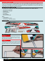
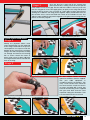
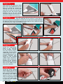
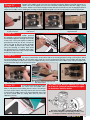
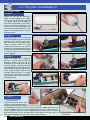
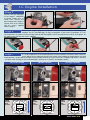
Electric Motor Installation
ELECTRIC MOTOR FITTING
Stage 1
Remove the pre-fitted IC engine
mount (4 bolts with spring washers
and washers). The mount and bolts
are no longer required but retain
the washers. Remove the battery
access hatch and remove the
captive nuts from behind the engine
mounting bulkhead. These will be
re-used to fit the electric motor.
1.1. Remove the engine mount screws
1.2. Remove the factory-fitted captive nuts
2.1. Mark the bulkhead for the motor mount
2.2. Drill the bulkhead for the mounting screws
Stage 2
By using the large fuel tank neck
location hole as a centre, mark the
positions of the mounting screws
on the bulkhead using the mounting
plate as a guide. If you are fitting
the recommended KMS motor
(quantum 4120/05), the two upper
holes for the IC mount are re-used
and only the lower ones need to be
drilled. Drill the mounting holes in
the bulkhead using a 5mm drill.
Stage 3
You will need to supply spacing
stand-offs for the motor you
have chosen. Motor lengths and fitting dimensions vary a lot
from make to make. For the KMS Quantum 4120/05 motor
they need to be 35mm long, 12mm wide with a 4.1mm internal
bore. For these spacers, you will need 45mm M4 bolts. You
can re-use the washers and spring washers from the original
mount. An optional spacer/screw kit is available with all that
you need for the KMS motor. Fix the captive nuts in the back
of new bulkhead holes and fit the motor using the screws
and washers detailed above (or appropriate to your motor).
Tighten the bolts so that the captive nuts are fully home in the
bulkhead. Do not let the wood of the bulkhead be crushed.
Stage 4
Fit the backplate of the spinner to the
propeller driver, then the propeller,
washer and nut. Note – The trailing
edge of the propeller should be in
contact with the small moulded posts
on the backplate. This is to align the
propeller with the cutouts in the spinner
cone. Make sure the main fixing nut
is securely tightened. Fix the spinner
cone to the backplate with the two self
tapping screws provided with it.
3.1. Fit the motor mount to the
motor
Stage 5
Complete the motor installation by
feeding the motor wires through the
hole in the bulkhead and into the
battery bay.
3.2. Fit the motor to the bulkhead
to use some more Velcro tape on the
face of the tray and the underside of the
battery (just 25mm is enough) to stop the
battery sliding. We also recommend fixing
a couple of balsa spacer blocks to the
rear of the bulkhead to prevent the battery
touching the captive mounting nuts and
bolts if it moves forward. Set the operation
of the motor/ESC by reference  to the ESC
instructions.
5.1. Motor wires go through the bulkhead
Stage 6
4.1. Fit the spinner backplate and propeller
12
Irvine Tutor 40 II
Mount the ESC (Electronic Speed
Controller) to the fuselage side using
adhesive foam tape. The battery is
retained in the tray by the Velcro
straps provided. It is a good idea
6.1. Attach your ESC with double sided tape