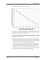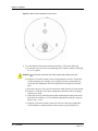
1
Trillium Seismometer User Guide Nanometrics Inc. Kanata, Ontario Canada © 2002–2004 Nanometrics Inc. All Rights Reserved. Trillium Seismometer User Guide The information in this document has been carefully reviewed and is believed to be reliable. Nanometrics, Inc. reserves the right to make changes at any time without notice to improve the reliability and function of the product. No part of this publication may be reproduced, stored in a retrieval system or transmitted, in any form or by any means, electronic, mechanical, photocopying, recording, or otherwise, without the prior written permission of Nanometrics Inc. Nanometrics, Inc. 250 Herzberg Road Kanata, Ontario, Canada K2K 2A1 Tel (613)592-6776 Fax (613)592-5929 Email [email protected] Part number 13912R10 Release date 2004-07-14 Contents Figures . . . . . . . . . . . . . . . . . . . . . . . . . . . . . . . . . . . . . . . . . . . . . . . . . . . . . . . . . . iii Tables . . . . . . . . . . . . . . . . . . . . . . . . . . . . . . . . . . . . . . . . . . . . . . . . . . . . . . . . . . v Chapter 1 Introduction . . . . . . . . . . . . . . . . . . . . . . . . . . . . . . . . . . . . . . . . . . . . . . . . . . . . . . 1 Chapter 2 Preparation. . . . . . . . . . . . . . . . . . . . . . . . . . . . . . . . . . . . . . . . . . . . . . . . . . . . . . . 3 2.1 Site Selection. . . . . . . . . . . . . . . . . . . . . . . . . . . . . . . . . . . . . . . . . . . . . . . . . . . . . . . . . . . . 2.2 Pier Construction . . . . . . . . . . . . . . . . . . . . . . . . . . . . . . . . . . . . . . . . . . . . . . . . . . . . . . . . . 2.2.1 Concrete Selection . . . . . . . . . . . . . . . . . . . . . . . . . . . . . . . . . . . . . . . . . . . . . . . . . . . . . . 2.2.2 Vault Wall Decoupling. . . . . . . . . . . . . . . . . . . . . . . . . . . . . . . . . . . . . . . . . . . . . . . . . . . . 2.3 Thermal Insulation . . . . . . . . . . . . . . . . . . . . . . . . . . . . . . . . . . . . . . . . . . . . . . . . . . . . . . . . 2.4 Cable Design . . . . . . . . . . . . . . . . . . . . . . . . . . . . . . . . . . . . . . . . . . . . . . . . . . . . . . . . . . . . 3 3 3 4 4 4 Chapter 3 Installation . . . . . . . . . . . . . . . . . . . . . . . . . . . . . . . . . . . . . . . . . . . . . . . . . . . . . . . 7 3.1 3.2 3.3 3.4 3.5 Unpacking . . . . . . . . . . . . . . . . . . . . . . . . . . . . . . . . . . . . . . . . . . . . . . . . . . . . . . . . . . . . . . 7 Orientation and Levelling . . . . . . . . . . . . . . . . . . . . . . . . . . . . . . . . . . . . . . . . . . . . . . . . . . . 7 Mass Centring (Optional). . . . . . . . . . . . . . . . . . . . . . . . . . . . . . . . . . . . . . . . . . . . . . . . . . . 8 Sensor Cable . . . . . . . . . . . . . . . . . . . . . . . . . . . . . . . . . . . . . . . . . . . . . . . . . . . . . . . . . . . 11 Checklist . . . . . . . . . . . . . . . . . . . . . . . . . . . . . . . . . . . . . . . . . . . . . . . . . . . . . . . . . . . . . . 11 Chapter 4 Operation . . . . . . . . . . . . . . . . . . . . . . . . . . . . . . . . . . . . . . . . . . . . . . . . . . . . . . . 13 4.1 External Connector . . . . . . . . . . . . . . . . . . . . . . . . . . . . . . . . . . . . . . . . . . . . . . . . . . . . . . 4.2 Power. . . . . . . . . . . . . . . . . . . . . . . . . . . . . . . . . . . . . . . . . . . . . . . . . . . . . . . . . . . . . . . . . 4.3 Output Signals . . . . . . . . . . . . . . . . . . . . . . . . . . . . . . . . . . . . . . . . . . . . . . . . . . . . . . . . . . 4.4 Frequency Response. . . . . . . . . . . . . . . . . . . . . . . . . . . . . . . . . . . . . . . . . . . . . . . . . . . . . 4.5 Self-Noise . . . . . . . . . . . . . . . . . . . . . . . . . . . . . . . . . . . . . . . . . . . . . . . . . . . . . . . . . . . . . 4.6 Calibration . . . . . . . . . . . . . . . . . . . . . . . . . . . . . . . . . . . . . . . . . . . . . . . . . . . . . . . . . . . . . 4.7 State-Of-Health . . . . . . . . . . . . . . . . . . . . . . . . . . . . . . . . . . . . . . . . . . . . . . . . . . . . . . . . . 4.8 Troubleshooting . . . . . . . . . . . . . . . . . . . . . . . . . . . . . . . . . . . . . . . . . . . . . . . . . . . . . . . . . 4.8.1 Fuse Replacement . . . . . . . . . . . . . . . . . . . . . . . . . . . . . . . . . . . . . . . . . . . . . . . . . . . . . 13 13 13 15 16 17 17 18 18 Appendix A Specifications . . . . . . . . . . . . . . . . . . . . . . . . . . . . . . . . . . . . . . . . . . . . . . . . . . . . 21 Appendix B Connector Pinout . . . . . . . . . . . . . . . . . . . . . . . . . . . . . . . . . . . . . . . . . . . . . . . . . 23 Appendix C Generic Sensor Cable . . . . . . . . . . . . . . . . . . . . . . . . . . . . . . . . . . . . . . . . . . . . . 25 i Contents ii Figures 3-1 3-2 3-3 4-1 4-2 4-3 Good sensor alignment example . . . . . . . . . . . . . . . . . . . . . . . . . . . . . . . . . . . . . . . . . . . . . . . 8 Mass position by expected operating temperature . . . . . . . . . . . . . . . . . . . . . . . . . . . . . . . . . . 9 Mass position adjustment access screws. . . . . . . . . . . . . . . . . . . . . . . . . . . . . . . . . . . . . . . . 10 Sensor axis orientations . . . . . . . . . . . . . . . . . . . . . . . . . . . . . . . . . . . . . . . . . . . . . . . . . . . . . 14 Nominal frequency response . . . . . . . . . . . . . . . . . . . . . . . . . . . . . . . . . . . . . . . . . . . . . . . . . 16 Self noise . . . . . . . . . . . . . . . . . . . . . . . . . . . . . . . . . . . . . . . . . . . . . . . . . . . . . . . . . . . . . . . . 17 iii Figures iv Tables 4-1 4-2 A-1 A-2 A-3 A-4 A-5 B-1 C-1 C-2 Axis orientation and polarity of XYZ outputs. . . . . . . . . . . . . . . . . . . . . . . . . . . . . . . . . . . . . . Poles and zeroes . . . . . . . . . . . . . . . . . . . . . . . . . . . . . . . . . . . . . . . . . . . . . . . . . . . . . . . . . . Performance specifications . . . . . . . . . . . . . . . . . . . . . . . . . . . . . . . . . . . . . . . . . . . . . . . . . . Operation specifications . . . . . . . . . . . . . . . . . . . . . . . . . . . . . . . . . . . . . . . . . . . . . . . . . . . . . Physical specifications . . . . . . . . . . . . . . . . . . . . . . . . . . . . . . . . . . . . . . . . . . . . . . . . . . . . . . Power specifications. . . . . . . . . . . . . . . . . . . . . . . . . . . . . . . . . . . . . . . . . . . . . . . . . . . . . . . . Environmental specifications . . . . . . . . . . . . . . . . . . . . . . . . . . . . . . . . . . . . . . . . . . . . . . . . . Connector pinout . . . . . . . . . . . . . . . . . . . . . . . . . . . . . . . . . . . . . . . . . . . . . . . . . . . . . . . . . . Generic sensor cable wiring for CBL13942R2 . . . . . . . . . . . . . . . . . . . . . . . . . . . . . . . . . . . . Generic sensor cable wiring for XYZ/UVW ± outputs of CBL13942R1 . . . . . . . . . . . . . . . . . 13 15 21 21 21 22 22 23 25 26 v Tables vi Chapter 1 Introduction Trillium is a three-component, force-balance broadband seismometer suitable for portable and fixed applications. It operates over a wide temperature range without manual recentring, and has very low power consumption. The extended response at higher frequencies makes it ideal for local and regional networks as well as volcano hazard monitoring and aftershock studies. Trillium uses a symmetrical triaxial arrangement of the sensing elements. The design uses fewer parts and ensures the same frequency response for vertical and horizontal outputs, and is less susceptible to rapid changes in temperature. Data output can be remotely switched between XYZ and UVW, allowing calibration of the elements independently of the electronics. UVW may be continuously recorded, if desired. Please read carefully the appropriate sections of this manual before transporting, storing, installing, or operating Trillium. If you need technical support, please submit your request by email or fax. Include a full explanation of the problem and supporting data, to help us direct your request to the most knowledgeable person for reply. Email: [email protected] FAX: To: Support (613) 592-5929 13912R10 2004-07-14 Trillium Seismometer User Guide 1 Chapter 1: Introduction 2 Trillium Seismometer User Guide 13912R10 2004-07-14 Chapter 2 Preparation This section provides preinstallation guidelines for Trillium. These guidelines are intended to help achieve the best possible performance, but are not necessary for all types of study (e.g. short-period) or site. 2.1 Site Selection There is no substitute for a geological survey when it comes to site selection, so that the structures over which the sensor is to be installed are known. Low porosity is important as water seepage through the rock can cause tilts which overwhelm the seismic signal at long periods. Clay soils and to a lesser extent sand are especially bad in this sense. A seismic sensor should be installed on bedrock whenever possible, and as far away as possible from sources of cultural noise such as roads, dwellings and other tall structures. 2.2 Pier Construction It is recommended that piers be rectangular (rather than round) whenever possible. This means that rigid foam insulation boxes can be easily made to fit. The pier should be 2" to 4" thick. The surface area should be sized to accommodate the sensors and associated cabling as well as any foam insulation boxes which are to be used. The surface of the pier should be as smooth and level as possible and clear of debris. 2.2.1 Concrete Selection The concrete used in a seismic pier should be as homogeneous as possible to avoid inducing tilts due to differing thermal coefficients of expansion. Therefore no aggregate should be used and the concrete should be free of air bubbles. Since strength is not a concern in a seismic pier no steel reinforcing is needed. The recommended mixture is 50% Portland cement and 50% sieved sand (see Uhrhammer et. al., 1997). After the concrete is poured it should be shaken to allow trapped bubbles to escape. The concrete will have sufficiently hardened to set up the sensor after 13912R10 2004-07-14 Trillium Seismometer User Guide 3 Chapter 2: Preparation 24 hours. However the pier may still generate spurious signals as the concrete cures which can take two to four weeks. 2.2.2 Vault Wall Decoupling When setting up the forms for the concrete be sure to include a gap between the edge of the concrete and the walls of the vault. This decoupling of the pier from the vault wall is important because otherwise wind or other non-seismic forces acting on the walls can be transferred to the pier causing it to tilt or twist, obscuring the desired seismic signal. These signals are mostly long-period and so this is less critical for shortperiod installations. 2.3 Thermal Insulation All broadband sensors are sensitive to temperature variations. Even at a very temperature-stable site, they must have some form of thermal insulation. Insulation serves to attenuate the ambient temperature variations, to isolate the sensor from drafts, and to localise and minimise air convection currents. We have repeatedly seen in our testing the critical importance of thermal insulation to long period noise performance with a variety of sensors and sites. We recommend a five-sided box constructed using rigid polystyrene or polyisocyanuratic foam insulation. Rigid foam is more portable and not as messy as styrofoam peanuts or fibreglass batting. The insulation should be at least 2" thick. Depending on the temperature stability of the site, additional or thicker boxes may be used. Joints should be glued using polystyrene adhesive or polyurethane resin, taking care to leave no gaps for drafts to enter through. Alternatively, rigid foam insulation with foil on one side can be used. There are two advantages to this kind of foam: it has a higher insulation resistance, and the joints can be made using packing tape which is quicker and less messy than glue. Adhesive 0.5" thick weatherstripping can be used to ensure a good seal between the bottom edge of the box and the pier. Be sure to cut a groove in the bottom of one edge of the box to allow the sensor cable to exit at the appropriate point. Because thermal insulation boxes are so light it is important to hold it firmly in place with something heavy. A brick works well for this purpose. Insulation boxes constructed of rigid foam must generally be constructed before visiting the site, but unfortunately they can be unwieldy to transport. In some cases, for example when a vault must be entered through a narrow doorway or for boreholes, other methods of thermal insulation will have to be considered. 2.4 Cable Design See Appendix B for connector pinouts. Sensor cables should be designed for good EMI shielding. This is most easily accomplished using double-shielded twisted-pair cable. The twisted pairs provide magnetic shielding, an inner shield grounded at the digitiser provides good electric field shield- 4 Trillium Seismometer User Guide 13912R10 2004-07-14 Chapter 2: Preparation ing, and a continuous outer shield provides good high-frequency RF shielding. The outer shield should be earthed at the digitiser for safety. The digital ground (DGND) must be used for the return currents of the control signals (CAL_SIG, U_CALEN, V_CALEN, W_CALEN, UVW and ACC). Note that the analog ground (AGND) is connected to chassis ground (CHGND) inside Trillium, so if these signals are already connected at the digitiser, AGND should not be connected through the cable or else a ground loop will be created. 13912R10 2004-07-14 Trillium Seismometer User Guide 5 Chapter 2: Preparation 6 Trillium Seismometer User Guide 13912R10 2004-07-14 Chapter 3 Installation Once the vault has been prepared, use the following procedures to install the Trillium. Provided at the end is a checklist for quality control at a typical installation. 3.1 Unpacking Trillium is shipped in a very sturdy triple-wall coated cardboard box with custom-cut cushioning foam. Open the box and set aside the user manual, maintenance kit and the top four layers of foam to completely expose the sensor. To minimize the possibility of damaging the sensor, do not remove it from the box until it is ready to be placed directly on the pier. Be sure to save the foam in case the sensor needs to be shipped again. 3.2 Orientation and Levelling Two methods of alignment are possible with Trillium: vertically scribed marks on the north-south axis and 3/8" diameter holes on the east-west axis. Levelling is accomplished using the three adjustable-height feet with lock nuts and the levelling bubble on the cover. The bubble accuracy is 0.5° per 2mm. While the sensor will operate properly with the bubble anywhere inside the black ring on the level, the bubble should be perfectly centred to avoid having to recentre the masses. The simplest way to align Trillium is using the north-south marks. Draw a line on the pier parallel to north-south. Take Trillium out of its box and place it gently down on the pier aligned approximately to north-south. Unlock the feet as required to level the sensor, and then lock them again by threading the lock nut up until it engages firmly with the base. It may be necessary to hold the body of the levelling foot still while locking the nut to avoid disturbing the levelness of the sensor. Now align the sensor precisely to north-south. It is very important to use the reflection of the line scribed on the pier in the sensor cover as an indication of misalignment and parallax. If the reflection of the pier line in the cover is at all curved, this is an indicator of parallax, i.e. you are not sighting the alignment marks from vertically above. If the pier line, its reflection, and the alignment marks in the base are not perfectly in line, then the sensor is misaligned (see Figure 3-1). 13912R10 2004-07-14 Trillium Seismometer User Guide 7 Chapter 3: Installation Figure 3-1 Good sensor alignment example After aligning the sensor to north-south, you may find that the sensor may need to be relevelled and then realigned. Note that for the most precise alignment possible two 3/8" diameter holes aligned to east-west are provided in the sensor base. However the north-south alignment marks will be precise enough for most installations. 3.3 Mass Centring (Optional) The Trillium masses are centred at the factory at 20°C. If the sensor is level, it will operate over the range ±35°C (–15°C to 55°C) without recentring. If the sensor is not levelled accurately then the operational temperature range will be reduced. Different operating ranges can be achieved by recentring the masses at different temperatures. For example, to achieve operation from –20°C to 50°C the masses should be centred at 15°C, or set on an offset at 20°C so that it will be centred at 15°C. Use the graph in Figure 3-2 to determine the offset. 8 Trillium Seismometer User Guide 13912R10 2004-07-14 Chapter 3: Installation Figure 3-2 Mass position by expected operating temperature The clip level below the corner frequency will be reduced at the temperature extremes. For example, a mass position of 2V results in a reduction of clip level below the lower corner frequency which is 6dB lower than normal. For these reasons, after temperature has stabilized in a new installation, it is good practice to physically recentre the boom. This maximizes the dynamic range of the sensor below the lower corner frequency. This procedure is simple, requiring only a 1.5mm hex screwdriver with a long shaft (provided in the Trillium maintenance kit) and any 2.5mm hex wrench or screwdriver: 1. Wait at least 4 hours for the temperature of the sensor case to come to equilibrium with the temperature of the vault before performing this procedure. 2. Measure the voltage on the mass position outputs of the three sensor channels. This can be easily accomplished when the digitiser is a Trident, by using a laptop running the Nanometrics user interface. If the mass positions are all within the range ±0.4V, then there is no need for recentring; otherwise continue to step 3. 3. Set the sensor in short-period response mode by shorting the ACC control signal to ground. This is also easily done using the Trident user interface. 13912R10 2004-07-14 Trillium Seismometer User Guide 9 Chapter 3: Installation Figure 3-3 Mass position adjustment access screws 4. For each channel with a mass position greater than ±0.4V, do the following: a) Locate the access seal screw corresponding to the channel of interest using Figure 3-3 as a guide. Caution Do not remove more than one of the access seal screws at any one time. b) Using the 2.5 mm hex wrench, remove the appropriate seal screw. Inspect the O-ring for damage (for example, cuts or pitting), and get a replacement seal screw from the maintenance kit if the original seal screw appears to be damaged. c) Place the seal screw where it will remain clean while the mass is being centred. d) Insert the 1.5 mm hex screwdriver straight down the hole to where it engages with the screw head. e) Adjust the screw by small increments while monitoring the mass position outputs until it is less than ±0.2 V. Note that the adjustment sensitivity is approximately 1turn = 1volt. f) Using the 2.5 mm hex wrench, replace the seal screw. Be sure to tighten the screw until there is metal-to-metal contact to ensure a good airtight seal. 10 Trillium Seismometer User Guide 13912R10 2004-07-14 Chapter 3: Installation 3.4 Sensor Cable Install the sensor cable. The cable should be strain-relieved to the pier at some point close to the sensor. This can be accomplished with tie-wraps and tie-wrap anchors, or with a heavy object. Ensure that the digitiser case is solidly earthed, and that the outer shield of the cable and the sensor case are thereby earthed. 3.5 Checklist The following checklist can be used as an aid when installing Trillium: Pier is clear of debris Sensor is level Sensor is aligned to north Sensor feet are locked Sensor serial number is noted Cable is connected to the sensor and the digitiser Cable is strain-relieved to the pier Cable is not touching the sensor case Thermal insulation is in place Thermal insulation is not touching the sensor or cables Thermal insulation is weighted down 13912R10 2004-07-14 Trillium Seismometer User Guide 11 Chapter 3: Installation 12 Trillium Seismometer User Guide 13912R10 2004-07-14 Chapter 4 Operation This section gives operating parameters and instructions for Trillium. 4.1 External Connector The Trillium connector is a 19-pin male military circular type hermetic connector. The pinout is given in Appendix B. 4.2 Power Trillium can be powered from 9V to 36V. Under normal operation the power consumption is approximately 0.6W. On startup the power may briefly rise to 1W. For very long cables, be sure to account for the resistive voltage drop due to the cable itself. For example 100m of 24AWG wire has a resistance of approximately 8.4Ω. Therefore on startup if the input voltage at the Trillium is 9V then the resistive drop due the peak current of 110mA will be 1.8V so the supply voltage must be at least 10.8V. 4.3 Output Signals A control signal switches the Trillium output signal to either UVW output or XYZ output. The “natural” sensor output is UVW; in this mode the outputs represent the actual motion of the masses of the three sensor components. The “conventional” sensor output is XYZ; in this mode the outputs represent horizontal and vertical motion. See Table 4-1 for the polarities of the XYZ outputs and their correspondence to the directions of the compass. Table 4-1 Axis orientation and polarity of XYZ outputs 13912R10 2004-07-14 Axis Orientation Positive voltage represents ... X east-west ... case motion to east Y north-south ... case motion to north Z vertical ... case motion upwards Trillium Seismometer User Guide 13 Chapter 4: Operation The UVW outputs are selected by shorting the UVW input to ground. If this input is left floating, then the XYZ outputs are selected. To understand the difference between the UVW and XYZ outputs, refer to Figure 4-1. The sensor axes have been designed so that they are identical and so that the directions in which they sense motion are orthogonal. Furthermore the U axis was chosen to be aligned with the east-west axis when projected into the horizontal plane. Figure 4-1 Sensor axis orientations Z V Y U W X This arrangement results in the following transformation equations: 2 0 u 1 v = ------- ⋅ – 1 3 6 w –1 – 3 x 1 y = ------- ⋅ 6 z 2 x ⋅ y 2 z 2 (EQ 1) 2 –1 –1 0 2 u ⋅ 3 – 3 v w 2 2 (EQ 2) The first equation is implemented mechanically in the orientation of Trillium’s individual sensor axes. The second equation is implemented electronically when Trillium is in XYZ mode. 14 Trillium Seismometer User Guide 13912R10 2004-07-14 Chapter 4: Operation Alternatively, seismic data may be digitised with Trillium in UVW mode and the transformation to horizontal and vertical signals implemented optionally when the data is processed. This allows for studies and calibrations where both UVW and XYZ data are required. 4.4 Frequency Response The nominal poles ( p n ), zeroes ( z n ), normalization factor ( k ), and normalization frequency of the Trillium are shown in Table 4-2. These parameters define the transfer function according to this equation: ∏ ( s + zn ) V⋅s n - ---------F(s) = S sensor ⋅ k ⋅ --------------------------m ( s + pn ) (EQ 3) ∏ n Table 4-2 Poles and zeroes Zeroes Nominal values Units 0 0 51.5 rad/s –272 ±218i Poles 56.5 rad/s –0.1111 ±0.1111i Normalization Factor 133310 Normalization Frequency 1 Hz The passband sensitivity is 1500V·s/m. The transfer function is approximately flat from 40s to 50Hz and rolls off at 40dB/decade below the lower corner frequency, as shown in Figure 4-2. 13912R10 2004-07-14 Trillium Seismometer User Guide 15 Chapter 4: Operation Figure 4-2 Nominal frequency response 66 64 62 Magnitude (dB wrt 1 V·s/m) 60 58 56 54 52 50 48 46 180 135 90 Phase (°) 45 0 -45 -90 -135 -180 10 -2 10 -1 10 0 10 1 10 2 Frequency (Hz) 4.5 Self-Noise Typical Trillium self-noise is plotted in Figure 4-3. Curves indicating Peterson’s new high- and low-noise models are included for reference. 16 Trillium Seismometer User Guide 13912R10 2004-07-14 Chapter 4: Operation Figure 4-3 Self noise -90 NHNM NLNM Trillium 40 -100 -110 PSD (dB m /s /Hz) -120 2 4 -130 -140 -150 -160 -170 -180 -190 -3 10 10 -2 -1 10 Frequency (Hz) 10 0 10 1 4.6 Calibration Calibration inputs are provided to allow for relative calibration of the sensor across frequency and over time. Since Trillium is a symmetric triaxial sensor, calibration must be performed on the individual sensor axes (UVW) rather than the horizontal and vertical outputs (XYZ). Individual axis outputs can be digitized by placing the sensor in UVW mode. This mode is activated by shorting the UVW input to ground. Each axis has a separate enable signal (U_CALEN, V_CALEN, W_CALEN) which is activated by shorting it to ground. All axes use a common input signal (CAL_SIG) which has a sensitivity of 0.010m/s2/V. 4.7 State-Of-Health Mass position outputs are provided to monitor the effect of tilt and temperature on the spring which sets the rest position of the boom. As with the calibration signals, they represent the state of the individual sensor axes (UVW) rather than the horizontal and vertical outputs (XYZ). The mass positions are zeroed at the factory at room temperature with Trillium perfectly level. 13912R10 2004-07-14 Trillium Seismometer User Guide 17 Chapter 4: Operation These outputs can be used to infer how much power the integrator is consuming to centre the boom, as well as whether the clip level of the instrument below the lower corner frequency is being reduced significantly. If the mass positions are all within the range ±0.4V, then there is no need for recentring. Otherwise follow the procedure in section 3.3 “Mass Centring (Optional)” on page 8. 4.8 Troubleshooting 4.8.1 Fuse Replacement The Trillium electronics on earlier models (up to serial number 179) are protected by a replaceable input fuse. Replacement fuses are provided in the maintenance kit that was shipped with the sensor. (Newer models—serial number 180 and higher—have a selfresetting fuse that does not need to be replaced.) The simplest way to check if the fuse is blown is to apply 12V across the input terminals using a power supply with a built-in current meter. If no current is drawn by the sensor then the fuse needs to be replaced. Since broadband seismometer mechanics are very sensitive to the presence of contamination such as dust, Trillium is assembled in a cleanroom environment. Fuse replacement should be performed in a cleanroom. If one is not available, return the sensor to the factory for maintenance. There is a desiccant inside the sensor case which must be replaced after exposure to moisture in the atmosphere. To limit exposure to moisture, fuse replacement must be done quickly, no more than 15 minutes total. To replace the fuse: 1. Remove the connector jam nut. 2. Remove the 3 screws in the top of the cover. Inspect the O-rings for cuts or pitting and set them aside. Make sure the circuit board drops a short distance down onto 3 standoffs (not yet visible). 3. With the sensor standing on its feet at the edge of a benchtop, remove the 12 screws which fasten the base to the cover. Carefully lift the cover straight up. 4. The fuse is located beside the main connector. Using needle-nose pliers remove the blown fuse and insert the new one. 5. Inspect the connector and base O-rings for damage and make sure they are seated correctly. 6. Carefully lower the cover over the mechanics and electronics. Again with the sensor at the edge of a benchtop, thread the 12 base screws finger tight only. At this point it may be desirable to turn the sensor upside-down to make it easier to torque the screws so that the base O-ring is fully compressed. 7. Use the 3 cover screws to pull the electronics up against the inside of the cover and then tighten them until metal-to-metal contact is felt. 8. Replace the connector jam nut. 18 Trillium Seismometer User Guide 13912R10 2004-07-14 Chapter 4: Operation Apply power to the sensor and check that the current stays below 125mA. When the sensor is level the power should be 0.6W. If the problem persists contact Nanometrics support (see Chapter 1, “Introduction”). 13912R10 2004-07-14 Trillium Seismometer User Guide 19 Chapter 4: Operation 20 Trillium Seismometer User Guide 13912R10 2004-07-14 Appendix A Specifications This section lists the specifications of Trillium. Table A-1 Performance specifications Parameter Specification Midband Generator Constant 1500V·s/m Clip Level 16V peak-to-peak differential Lower Corner Frequency 0.025Hz Lower Corner Damping relative to Critical 0.707 Upper Corner Frequency 50Hz Table A-2 Operation specifications Parameter Specification Measurement Axis Orientation symmetric triaxial Output Axis Orientation vertical, north, east Displacement Transducer Type capacitive Feedback Type coil-magnet Mass Lock none required Mass Centring optional manual Calibration Enable separate UVW enables Control Inputs open-drain active-low Table A-3 Physical specifications 13912R10 2004-07-14 Parameter Specification Base Diameter 22cm Maximum Height Including Feet 18cm Total Weight 11kg Connector 19-pin military circular Trillium Seismometer User Guide 21 Appendix A: Specifications Table A-4 Power specifications Parameter Specification Input Voltage Range 9V to 36V Maximum Power Consumption (when level) 0.6W Overvoltage Protection included Short-circuit Protection 0.125A fuse (replaceable) 0.3A fuse (self-resetting) Reverse Voltage Protection series diode Table A-5 Environmental specifications 22 Parameter Specification Operating Temperature Range –20°C to 50°C Operating Range Without Recentring ±35°C Trillium Seismometer User Guide 13912R10 2004-07-14 Appendix B Connector Pinout The Trillium connector is a 19-pin male military circular type hermetic connector. The pinout is given in Table B-1. Table B-1 Connector pinout 13912R10 2004-07-14 Pin Name L Z+/W+ M Z–/W– N Y+/V+ A Y–/V– P X+/U+ B X–/U– T CAL_SIG K U_CALEN J V_CALEN U W_CALEN E U_MP F V_MP S W_MP Function Type vertical (W axis) output north/south (V axis) output 16Vpeak-to-peak differential east/west (U axis) output calibration signal input 13.6kΩ input impedance calibration enable inputs active-low open-drain mass position outputs ±4.5V single-ended N/A V AGND analog ground H +PWR power input G –PWR power return D UVW enable single-ended UVW instead of differential XYZ outputs C ACC enable short-period response for testing and mass centring R DGND digital ground N/A shell CHASSIS for shielding and safety N/A 9V to 36V DC isolated active-low open-drain Trillium Seismometer User Guide 23 Appendix B: Connector Pinout 24 Trillium Seismometer User Guide 13912R10 2004-07-14 Generic Sensor Cable Appendix C A generic sensor cable may have been shipped with your sensor. Table C-1 is the wiring key for the standard cable (Nanometrics part number CBL13942R2). This table can be used as a reference when wiring the generic sensor cable end to a digitiser connector. Note If you are using the earlier version of the generic sensor cable (Nanometrics part number CBL13942R1), refer to Table C-2 for the wiring of the XYZ/UVW ± outputs; these are in inverse order to the standard cable. The rest of the wiring is the same as for CBL13942R2 shown in Table C-1. Table C-1 Generic sensor cable wiring for CBL13942R2 From Conn Pin To Name Conn Name Colour Run P1 L Z+/W+ P2 CH1+ RED 1 P1 M Z–/W– P2 CH1– BLK 1 P2 CH1GND DRAIN 1 P1 N Y+/V+ P2 CH2+ WHT 2 P1 A Y–/V– P2 CH2– BLK 2 P2 CH2GND DRAIN 2 P1 P X+/U+ P2 CH3+ GRN 3 P1 B X–/U– P2 CH3– BLK 3 P2 CH3GND DRAIN 3 P1 T CAL_SIG P2 CAL1+ BLU 4 P1 U W_CALEN P2 CAL1–/CTRL4 BLK 4 SHELL P2 SHELL DRAIN 4 P1 P1 P1 P1 P1 J V_CALEN P2 CAL2–/CTRL5 YEL 5 P1 K U_CALEN P2 CAL3–/CTRL6 BLK 5 P1 SHELL P2 SHELL DRAIN 5 P1 S W_MP P2 EXT_SOH1 BRN 6 P1 F V_MP P2 EXT_SOH2 BLK 6 SHELL P2 SHELL DRAIN 6 U_MP P2 EXT_SOH3 ORG 7 P1 P1 13912R10 2004-07-14 Pin Wire E Trillium Seismometer User Guide 25 Appendix C: Generic Sensor Cable Table C-1 Generic sensor cable wiring for CBL13942R2 (Continued) From To Conn Pin Name Conn P1 V AGND P1 SHELL +BAT P1 P1 H P1 G P1 Pin Wire Run Name Colour CH1GND BLK 7 P2 SHELL DRN 7 P2 SEN+12V RED 8 –BAT P2 SENRTN WHT 8 SHELL P2 SHELL DRAIN 8 P1 D UVW P2 CTRL1 RED 9 P1 C ACC P2 CTRL2 GRN 9 P1 R DGND P2 DGND DRAIN 9 SHELL P2 SHELL BRAID P1 Table C-2 Generic sensor cable wiring for XYZ/UVW ± outputs of CBL13942R1 From To Pin Name Conn Name Colour P1 L Z+/W+ P2 CH1+ BLK 1 P1 M Z–/W– P2 CH1– RED 1 P2 CH1GND DRAIN 1 P1 N Y+/V+ P2 CH2+ BLK 2 P1 A Y–/V– P2 CH2– WHT 2 P2 CH2GND DRAIN 2 P1 P X+/U+ P2 CH3+ BLK 3 P1 B X–/U– P2 CH3– GRN 3 P2 CH3GND DRAIN 3 P1 P1 26 Run Conn P1 Trillium Seismometer User Guide Pin Wire 13912R10 2004-07-14