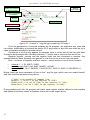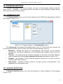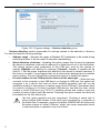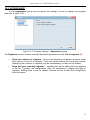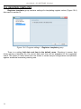
1
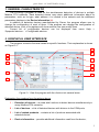
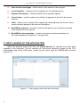
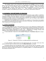
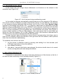
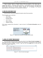
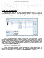
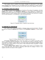
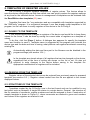
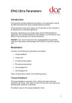
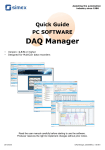
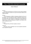
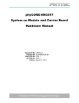
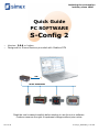
Assisting the automation
industry since 1986
Quick Guide
PC SOFTWARE
S-Config 2
•
•
Version: 2.0.6 or higher
Designed for Simex devices provided with Modbus RTU
USB
RS-485 / MODBUSRTU
Read the user's manual carefully before starting to use the unit or software.
Producer reserves the right to implement changes without prior notice.
2012.12.20
S-Config 2_QGUSXEN_v.1.00.002
Quick Guide - PC SOFTWARE S-Config 2
CONTENTS
1. GENERAL CHARACTERISTIC...................................................................................................................3
2. GRAPHICAL USER INTERFACE...............................................................................................................3
3. FIRST LAUNCH OF THE APPLICATION...................................................................................................4
4. SCANNING THE NETWORK OF DEVICES...............................................................................................5
4.1. DETECTION MODE...........................................................................................................................5
4.2. READDRESSING MODE...................................................................................................................6
5. RELATED PRODUCTS...............................................................................................................................6
6. DEVICE INFORMATION..............................................................................................................................7
7. AREA OF EVENT MESSAGES..................................................................................................................7
8. THE LIST OF REGISTERS.........................................................................................................................8
8.1. THE LIST OF REGISTERS VIEWS...................................................................................................8
8.2. SEARCHING REGISTERS................................................................................................................9
8.3. CHANGING THE REGISTER VALUE...............................................................................................9
8.4. READING FROM THE DEVICE.......................................................................................................10
8.5. WRITING TO THE DEVICE.............................................................................................................10
9. TEMPLATES OF REGISTER VALUES....................................................................................................11
9.1. SAVING TO THE TEMPLATE.........................................................................................................11
9.2. READING FROM THE TEMPLATE.................................................................................................11
9.3. STRUCTURE OF THE TEMPLATE.................................................................................................11
10. PROGRAM SETTINGS...........................................................................................................................13
10.1. COMMUNICATION.........................................................................................................................13
10.2. DEVICES DETECTION..................................................................................................................13
10.3. APPEARANCE...............................................................................................................................15
10.4. REGISTERS TEMPLATES............................................................................................................16
Explanation of symbols used in the manual:
!
i
2
This symbol denotes especially important characteristics of the software operation.
Read any information regarding this symbol carefully.
This symbol indicates additional information that may help operate the program.
Quick Guide - PC SOFTWARE S-Config 2
1. GENERAL CHARACTERISTIC
The S-Config 2 program is used for the simultaneous detection of devices in multiple
Modbus RTU networks. Each detected device may return additional information about its
parameters, such as its type, what address it is located in the network and the additional
parameters displays in the Device information (4).
In addition to detection devices manufactured by Simex, the program allows user to
change the configuration of most of them. If the program can change the configuration of
detected device, a list of its registers will show and the user can modify them.
Current list of configurable devices can be displayed from menu Help >
Supported devices... > Configurable devices.
2. GRAPHICAL USER INTERFACE
The program consists of several areas for specific functions. Their explanation is shown
on Figure 2.1.
9
8
1
2
11
3
7
6
4
10
5
Figure 2.1. View the program with the division into several areas
Explanation the numbers from the picture above:
1 – Detection of devices – an area with functions to detect devices simultaneously in
many Modbus RTU networks;
2 – List of devices – a list of detected devices with division to the COM ports;
3 – List of related products – contains a list of products associated with
selected device;
4 – Device information – provides additional information read from the device;
3
Quick Guide - PC SOFTWARE S-Config 2
5 – Area of event messages – allows user to view events of the program;
6 – List of registers – displays a list of registers for the selected device;
7 – Register information – contains details of the selected register;
8 – List of views – used for reduce the visibility of registers on the list 6 by chosen
criterion;
9 – Filter – allows user to quickly find a register by narrowing down the list 6 to items
contain entered phrase in the name or description;
10 – Read/Write registers – provides functions that allows user to perform read and
write operations on the device;
11 – Read/Write value templates – contains functions to perform operations on
the value templates of registers (*.scg type files);
3. FIRST LAUNCH OF THE APPLICATION
When the program launch first time, the List of devices (2) contains only serial ports
available in the computer. This list contains all COM ports physically located on the PC's
motherboard and virtual COM ports created by the driver such as USB/RS-485 converter
(Figure 3.1).
Figure 3.1. The program state after the first launch
4
Quick Guide - PC SOFTWARE S-Config 2
The program doesn't have information what devices are available at any of the listed
ports. The first thing that user should do is to set parameters of the COM ports to be scanned.
To do this, go to the settings using the menu Tools > Settings..., select the position
Communication, uncheck unused ports and adjust the parameters of the rest. For more
information on port settings see section 10.1. . After completion and apply settings, the
program is ready to start searching for devices. This process is discussed in section 4. .
4. SCANNING THE NETWORK OF DEVICES
The program has the ability to scan the network of devices in two modes. In detection
mode the program searches networks on selected or all displayed COM ports by checking the
availability of device at each address and if any is detected, the program will automatically
recognize it and add to the list. In the readdressing mode the user can assign unique address
in an automatic way to all devices on the network.
Regardless of the selected scan mode, after the completion of this process, the program
will create a list of devices that will be saved to the time of next scan. Last saved devices list is
also remembered if the program will restart.
4.1. DETECTION MODE
This mode allows the user to find all devices in one or more networks by scanning each
address of Modbus RTU protocol. In order to accelerate the network scanning, this process is
done independently for each COM port. The range of addresses that will be tested, user can
specify in the settings described in section 10.2. . Regardless of settings, devices with
addresses FEh (254) and FFh (255 or 0) are always tried to discover.
To start detection of devices on all available COM ports, click [Detect all] button (Figure
4.1).
Figure 4.1. Detection of devices in multiple networks simultaneously
It is also possible to detect devices on the selected port only. To do this, click one of the
ports on the list, open its context menu and click [Start detection] command.
All detected devices are automatically saved. If some devices were not detected, it may
mean that responses that they sends reach to the program too late, so user can try to increase
the time for response of the quick detection or completely disable it. For detailed description of
this feature see section 10.2. .
5
Quick Guide - PC SOFTWARE S-Config 2
4.2. READDRESSING MODE
In this mode user can assign unique addresses to all devices on the network in the
automatic way (Figure 4.2).
Figure 4.2. List of devices during readdressing mode
In this mode the program automatically searches devices on the network at FFh address.
Once such a device is detected, program automatically assign it a new address. The program
is not checking existing addresses and set them one by one of the range Address range
specified in the settings (see section 10.2. ). For devices, where there is a possibility to set the
address using its configuration menu (e.g. SIMPACT series devices), should set it to FFh (255)
and wait until S-Config 2 detects such device. If it is impossible to set the device address to
FFh, it can also achieved by set the address 00h. Once detected one device, the program is
ready to detect another on FFh (or 00h) address. User must ensure that no more than one
device at a time has address FFh (or 00h). Otherwise, none of the devices is detected and in
extreme cases it can lead to damage their RS-485 interfaces.
Devices that don't have the keyboard, should have a special button that allows user to
force set FFh address. Brand new devices of this type have set FEh address, which protects
them from the automatic readdressing.
To readdress such device user must:
1. set the device in detection mode by pressing and holding for a few seconds (until
LED lights up) button to force the address;
2. then release the button;
3. after about 1 second, that button was released, the device should return to its normal
mode (running state) with new assigned address.
5. RELATED PRODUCTS
If computer is connected to the Internet and was selected one of the devices on the list, it
will show a panel containing a list of related products (Figure 5.1).
Figure 5.1. List of related products
6
Quick Guide - PC SOFTWARE S-Config 2
These products relate to selected device and are products of the same type or
cooperating products. Information about products is downloaded from the manufacturer's
website. By clicking on the selected product, user can open informative web page with
downloadable resources like manuals, software updates, etc. The language of the opened
page depends on the settings of the manufacturer's website.
6. DEVICE INFORMATION
Some devices can provide detailed information about their properties.
This information are in particular:
device type
•
serial number
•
firmware version
•
type of inputs
•
type of outputs
•
number of relays
•
If the device supports this information, it can be found in the Product Information area (4)
(Figure 6.1).
Figure 6.1. Additional information returned by the device
7. AREA OF EVENT MESSAGES
Any information that the program doing are printed in the Area of event messages (3).
This makes possible to identify any problems and anomalies in communication with devices.
By default, this area is hidden. To show it, user can click the [Log] button on the lower left
area of the program (Figure 7.1).
Figure 7.1. Area of event messages
7
Quick Guide - PC SOFTWARE S-Config 2
If appears an event that requires the user attention, such as communication error, this
area will show automatically.
Information appearing here are also saved into the “EventLog.txt” file, which is located in
the main directory of the program.
8. THE LIST OF REGISTERS
After the network scan, user can select one of detected devices. If there is a device for
which the program can change its configuration, that after selected it, the S-Config 2 program
tries automatically read its current values of registers (Figure 8.1). This process may take a
while because the program must read values of all registers available for the device, but later
writing changes entered by the user may affect modified registers only, what is much faster
process.
Figure 8.1. List of registers and their values read from the selected device
Each of the displayed register consists of a short name, which may include a register
number compatible with the manual of the device. Displaying these numbers can be turned off
from the program settings (see section 10.3. ). Besides the name, each register has a current
value and unit. When the user selects any of them, he will see more detailed information, such
as the scope for value changes and more extensive description of the function which it serves.
It appears in the Register information (7).
8.1. THE LIST OF REGISTERS VIEWS
Devices often contain quite large number of registers. Most of them are rarely used. To
help user set-up, the program has the ability to hide displaying much advanced registers or
registers with other criteria. This is done by using the List of views (8).(Figure 8.2).
8
Quick Guide - PC SOFTWARE S-Config 2
Figure 8.2. The list of registers views
The list of views contains predefined criteria which registers are displayed. The user can't
define its own views.
8.2. SEARCHING REGISTERS
In order to easily find registers of interest to user, a program can narrow the list to only
registers that contain typed phrase. Searching is done in the names of registers and their
descriptions. The size of typed characters in the Filter field doesn't matter (Figure 8.3).
Figure 8.3. Example of display registers which contain the “out” phrase
8.3. CHANGING THE REGISTER VALUE
To modify the value of register user should click inside the Value column. This will open
specific editor different for various types of registers (Figure 8.4).
Figure 8.4. Different editors for various types of registers
Values possible to set are depending on the selected register. During modification of
numerical values by using the keyboard, should pay attention to the possible range of
changes, which is shown in the Register information (7).
9
Quick Guide - PC SOFTWARE S-Config 2
If the register value is modified, the program changes its texts format. If user makes
many changes and he change his mind, the program gives him possibility to restore them by
clicking [Undo] button. Undo function works until the next read or write registers to the device.
8.4. READING FROM THE DEVICE
To read the entire device configuration in the form of the values of its registers, click the
[Read] button located in the Read/Write registers (3) area (Figure 8.5). Executing this
command will update values of all registers in the program regardless they are visible or not.
Between values in various registers there are software connections and because to maintain
their full synchronization, is not possible to read only selected ones.
Figure 8.5. Reading values of registers from the device
8.5. WRITING TO THE DEVICE
After modify values of selected registers, changes can be saved to the device. This can
be done by clicking the [Write] button located in the Read/Write registers (3) area (Figure
8.6).
Figure 8.6. Writing changed values of registers to the device
Unchecked Changed only option cause that values of all registers will write to the
device, regardless they have changed or not. Unchecking this option is especially useful if
user wants to configure multiple devices of the same type using prepared template without
read every time current values of every device. More information about templates of values
can be found in section 9. .
Checking Read all after writing causes reading current values of all registers of the
device after each write. This option is especially useful when the change of value in one
register can affect on values in other registers.
10
Quick Guide - PC SOFTWARE S-Config 2
9. TEMPLATES OF REGISTER VALUES
The S-Config 2 program supports templates of register values. This feature allows to
save the device configuration as files from which user can quickly restore the registers settings
at any time for the selected device. Access to management of templates can be obtained from
the Read/Write value templates (11) area.
Template files have the *.scg extension and are compatible with templates supported by
the “SMConfig” program. It is convenient because if user has already made templates in this
program, he can use them to modify registers of the device in the S-Config 2.
9.1. SAVING TO THE TEMPLATE
If user makes appropriate changes in registers of the device and would like to keep these
values for the future, it can be done by saving the current state of registers as a template of
values.
To do this, click the [Save...] button. A dialogue box appears for specify the template
name and location to save it. Template name is suggested by the program and includes the
device type and the date and time of saving, what protects user against accidental overwriting
existing file.
i
Automatically adding the date and time part to the filename can be disabled in the
program settings (see section 10.4. ).
!
In the template are stored values of all registers that can be changed on the device,
regardless that at the time of writing are shown on the list or not. It's also not
required to write changes to the device before saving to the template file.
Appropriate modifications of registers will be included.
9.2. READING FROM THE TEMPLATE
Register values of the selected device can be restored from previously saved or prepared
template (see section 9.3. ). Register values loaded from the file are applied to the current
displayed values.
9.3. STRUCTURE OF THE TEMPLATE
Templates created by the S-Config 2 are in the text format and can be modified in any
text editor such as Notepad. A single file relates to a single device. General, the structure of
the file consists of comments, register numbers and values assigned to them. Construction of
sample template is shown in Figure 9.1, where comments are marked in green and numbers
and values of the registers are marked in red.
11
Quick Guide - PC SOFTWARE S-Config 2
Device
description
Name and version
of the program
Creation tmestamp
of tempate
Device
identifier
Register name
Register number
Register value
Figure 9.1. Content of *.scg file type created by S-Config 2
From the perspective of read the template by the program, are important only rows with
red values. Additionally is checked the device ID (if any exists) to alert the user when he try to
open a template intended for another device.
Comments in the file may appear as separate lines or at the end of the line with data.
Comment always begin with a double character “/” (slash) and is valid until the end of line.
Register number, comma and the register value are one command to execute. Any
spaces between these elements are ignored. In one line can be at most one command.
Both – numbers of registers and their values – can be written in one of three formats:
•
•
•
decimal: 1, 3, 35, 43975, 31886
hexadecimal: 0x001, 0x3, 0x23, 0xABC7, 0x7c8E
binary: 0b0001, 0b11, 0b100011, 0b1010101111000111, 0b0111110010001110
Below, there are some examples of lines in the *.scg file type, which user can create himself,
and then load the template to any device.
// This is an example of comment line
0x0010,1 // write 1 to the register 16 (10h)
0x0011,0x12 // write 18 (12h) to the register 17 (11h)
0x00A,0b11 // write 3 (11b) to the register 10 (0Ah)
During reading such file, the program will check each register number defined in the template
and update only those values to registers, that occur in the target device.
12
Quick Guide - PC SOFTWARE S-Config 2
10. PROGRAM SETTINGS
To adapt the program to the user needs, can enter to the program settings using the
menu Tools... > Settings.... The settings window consists of several separate logical groups,
which are discussed in subsections.
10.1. COMMUNICATION
In Communication group can be found settings of the COM ports parameters used by
the program (Figure 10.1).
Figure 10.1. Program settings – Communication group
The Used ports list contains all available ports in the PC. Ports which are checked, will
be used by the program. Each of them can have individual settings, such as:
Baudrate – defines the speed of communication with devices on the network.
•
Devices with set different speed will not be detected and configure them will not be
possible.
Timeout – the waiting time for a device response. In the case of devices detection
•
may be replaced by setting Quick detection of devices discussed in section 10.2. .
Repeats – the number of retries that the program should do if an error occurs in
•
communication with a device.
Data format – specifies a frame format of the data used for communication. This
•
parameter is for information only.
10.2. DEVICES DETECTION
In Devices detection group can be found settings on various subjects of the program
(Figure 10.2).
13
Quick Guide - PC SOFTWARE S-Config 2
Figure 10.2. Program settings – Devices detection group
Devices detection section responsible for settings related to the detection of devices.
You can find here the following settings:
Address range – Specifies the range of Modbus RTU addresses to be tested during
•
searching devices or will be used for automatic readdressing.
Quick detection of devices – Enabling this option causes that the time for response
•
the device in detection mode will be reduced to a fixed timeout set in the field below.
This setting ignores some parameters of the COM port, such as the number of
repeats (Repeats) and waiting for response (Timeout). Number of repeats will be
fixed to 1. Set the proper response time affects for the speed of network scanning. If
this time is too short, it may happen that not all devices are detected and in extreme
cases nothing. The user should then increase the timeout or disable this option.
Prevent creation of new COM ports for devices of the same type – When the user
•
connects to the computer a new USB device or change its USB port, the system will
recognize it as a device that had not been installed previously and will run the
installation wizard of new drivers. It creates a new virtual COM port. Sometimes there
is a need to configure in S-Config 2 multiple USB devices, one after the other, which
creates a virtual COM port (e.g. SPT-61), installing drivers and create a new port
number for each of them would be tedious. Checking this option causes the driver will
be installed for the first device only.
!
14
Use this option carefully and only temporarily. Checking it cause lack of
using multiple USB devices of the same type connected to a computer at
the same time For example, several converters USB/RS-485 will be seen by
the same number of virtual COM port, which can cause unexpected errors
in communication or operation only one of them.
Quick Guide - PC SOFTWARE S-Config 2
10.3. APPEARANCE
In the Appearance group can be adjust the settings of how to display the program
elements (Figure 10.3).
Figure 10.3. Program settings – Appearance group
The Registers section contains settings that affect appearance of the List of registers (6):
•
•
Show the numbers of registers – turns on/off displaying of register numbers inside
their names on the list of registers. If the user rarely reaches for the device manual,
displaying the numbers of registers may be unnecessary, so they can be hidden.
Show and pool read-only registers – enabling this option adds read-only registers
to the list. Typically, the configuration does not necessary to display this type of
registers. Adding them to the list causes increase of time to read the configuration
from the device.
15
Quick Guide - PC SOFTWARE S-Config 2
10.4. REGISTERS TEMPLATES
Registers templates group contains settings for templating register values (Figure 10.4)
discussed in section 9. .
Figure 10.4. Program settings – Registers templates group
There is a setting Add date and time to the default name. Checking it causes, that
during saving a template file, the current date and time will be appended to the suggested
name. This option is useful when the user wants to create unique configurations and protects
against accidental overwriting existing one.
16
Quick Guide - PC SOFTWARE S-Config 2
System requirements:
- Operating system: Windows XP (32-bit) or later
- processor Pentium/AMD 600 MHz or faster
- 128 MB of RAM or more
- 50 MB or more free disk space
- monitor with min. resolution SVGA (800x600)
- CD-ROM or DVD-ROM
- keyboard and pointing device (e.g. mouse)
17
Quick Guide - PC SOFTWARE S-Config 2
18
Quick Guide - PC SOFTWARE S-Config 2
19
SIMEX Sp. z o.o.
ul. Wielopole 7
80-556 Gdańsk
Poland
tel.: (+48 58) 762-07-77
fax: (+48 58) 762-07-70
http://www.simex.pl
e-mail: [email protected]