1
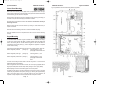
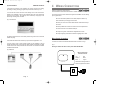
4344R12.qxd
03/09/99 11:09
Page 2
GARDTEC 800 Series
IMPORTANT!
Input:
AC230V +/-10% ~50Hz 200mA Max. 49W Max
Nominal Temp Range: 0 - 50°C
Gardtec 800 Series Metal Versions
For Indoor Use Only
Gardtec 800 Series Plastic Versions
For Indoor Use Only
This equipment is intended only for use as a Security Alarm Control Panel. Adequate ventilation
away from heat and humidity must be provided. The unit must be fixed securely to a nonflammable surface using suitable fixings.
All mains wiring must be to BS7671 (1992) IEEE wiring regulations (or appropriate international
regulatory standards). See Mains Supply Connection section within this manual for more
detailed instructions.
All wiring must be protected from sharp or jagged edges.
All Low voltage (alarm) wiring must be to the appropriate international regulatory standards and
comply to good wiring practice.
Replacement fuses should be of the same type and rating conforming to IEC 127.
1 INTRODUCTION
The Gardtec 800 Series of control panels consists of two main parts, The master
control panel and the keypad(s). The master control panel is a blank end station if the
metal version is used or, the keypad may be mounted on board if the polycarbonate
version is used with standard type keypads. Various zone wiring modes may be used
taking the maximum number of zones available on any one system to 80 zones with 3
areas for the Gardtec 840, 32 zones for the Gardtec 816 and 16 zones for the Gardtec
800. Zone expansion is via flexible zone expander cards on all models except the
Gardtec 800.
Ample room is provided within the master control panel housing for all the system
wiring, Mains connections, Digicom, Modem or Red-Care communicator (fitting inside
the metal version only) and a 7Ah SLA battery.
Uploading/Downloading capabilities are possible on all models within the range
through the Gardtec 800 Series Modem and the Gardtec Remote Software Package
for a P.C. Facility is also provided for direct connection to a P.C via the Gardtec 800
Series Modem Patch Lead.
The capabilities of the Gardtec 800 Series of control panels are endless and we
strongly recommend that all the manuals (both engineer and user) are read and
understood before any installation of the system is carried out. You will find that a little
time spent now understanding the Gardtec 800 Series will prove to be a great time
saver for the future.
It must be stressed that the Gardtec 840 is one system that is capable of being
split into three areas. Under no circumstances should you regard it as three
separate systems.
The maximum current draw from the unit for all output combinations must not exceed 1Amp.
The unit is intended for use with a suitable re-chargeable lead acid battery permanently
connected to the appropriate terminals.
All documentation and manuals must be thoroughly read by suitably qualified installation
personnel prior to installation.
The unit has no user serviceable parts inside. Internal access should only be by suitably qualified personnel.
Gardtec 800 Series Metal Versions
The unit must be Earthed. It is the responsibility of the installation engineer to ensure that the
earth connection to the unit lid is good on completion of the installation or after service.
Any references to Area Setting or Area
Functions contained in this manual relate to
the Gardtec 840 ONLY.
Gardtec 800 Series Plastic Versions
Provision is provided for an earth connection within the mains input connector block, this connection is for protection of the wiring only and is not functional for the unit.
Page 2
Page 3