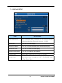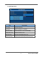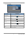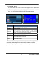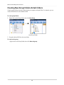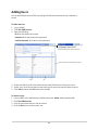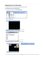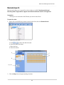
1
DIGITAL VIDEO RECORDER
USER GUIDE
4 / 8 CHANNELS
VER V1.0(C11)
• Thank you for purchasing this Digital Video Recorder.
• Before using the Digital Video Recorder, please ensure that you read and
understand the User Guide.
• Please store the User Guide at an easily accessible location.
• Before connecting and installing any third party cameras, monitors, alarms and
computers, please refer to the appropriate instruction manual for proper operation.
.. SAFETY PRECAUTIONS
CAUTION:
TO REDUCE THE RISK OF ELECTRIC SHOCK, DO NOT REMOVE COVER (OR BACK).
NO USER SERVICEABLE PARTS INSIDE. REFER SERVICING TO QUALIFIED
SERVICE PERSONNEL.
The lightning flash with arrowhead symbol, within an equilateral
triangle, is intended to alert the user to the presence of un insulated
“dangerous voltage” within the product’s enclosure that may be of
sufficient magnitude to constitute a risk of electric shock to persons.
The exclamation point within an equilateral triangle is intended to alert
the user to the presence of important operating and maintenance
(servicing) instructions in the literature accompanying the appliance.
WARNING:
TO PREVENT FIRE OR ELECTRIC SHOCK HAZARD,
DO NOT EXPOSE THIS APPLIANCE TO RAIN OR MOISTURE.
1
DIGITAL VIDEO RECORDER
Contents
Disclaimer ............................................................................................... 4
Warning ................................................................................................... 4
Caution .................................................................................................... 6
Preventing Malfunction .......................................................................... 6
Package Contents .................................................................................. 7
1. Front Panel ...................................................................................................... 8
2. Rear Panel Connectors .................................................................................. 9
3. Remote Controller ........................................................................................ 10
II. INSTALLATION & CONNECTIONS .................................................. 11
1. Camera, Monitor, Microphone, Alarm sensor and Power cord ................. 11
2. PC system requirement for Network connection. ...................................... 14
III. OPERATIONS ................................................................................... 15
1. LIVE MODE ................................................................................................... 15
2. PLAYBACK MODE ........................................................................................ 18
3. PTZ MODE .................................................................................................... 19
IV. MAIN MENU...................................................................................... 20
1. RECORD SETUP .......................................................................................... 21
1.1. RECORD SETUP ........................................................................................ 21
1.2. QUALITY & FRAME RATE SETUP ............................................................ 22
2. EVENT SETUP .............................................................................................. 23
2.1. MOTION SETUP .............................................................................................................23
2.2. MOTION AREA SETUP ..................................................................................................24
2.3. SENSOR SETUP ............................................................................................................25
3. SCHEDULE SETUP ....................................................................................... 26
3.1. SCHEDULE SETUP .................................................................................... 26
3.2. SCHEDULE RECORD SETUP ................................................................... 27
3.3. HOLIDAY SETUP ........................................................................................ 27
4. CAMERA SETUP .......................................................................................... 28
5. PTZ SETUP ................................................................................................... 29
6. NETWORK SETUP ....................................................................................... 30
6.1. DHCP .......................................................................................................... 30
6.2. STATIC IP .................................................................................................... 31
6.3. ADSL ........................................................................................................... 31
6.4. HTTP SETUP .............................................................................................. 32
6.5. DDNS SETUP ............................................................................................. 33
2
DIGITAL VIDEO RECORDER
6.6. MAIL SETUP ............................................................................................... 34
7. SYSTEM SETUP ........................................................................................... 35
7.1. DISPLAY SETUP......................................................................................... 36
7.2. DATE/TIME SETUP ..................................................................................... 37
7.3. DEVICE SETUP .......................................................................................... 38
7.4. AV OUTPUT SETUP ................................................................................... 39
7.5. ACCOUNT SETUP ...................................................................................... 40
8. UTILITIES ...................................................................................................... 41
V. BACKUP & SEARCH ........................................................................ 43
1. BACKUP SETUP ........................................................................................... 43
2. SEARCH SETUP ........................................................................................... 44
2.1. EVENT SEARCH......................................................................................... 44
2.2. TIME SEARCH ............................................................................................ 46
Appendix 1: SPECIFICATION ........................................................................... 47
Appendix 2: EMS S/W....................................................................................... 49
Appendix 3: REMOTE VIEW ON MAC ............................................................. 86
Appendix 4: REMOTE VIEW ON PC ................................................................ 92
Appendix 5: MOBILE APPLICATION ............................................................... 94
3
DIGITAL VIDEO RECORDER
Disclaimer
z The information in this manual is believed to be accurate and reliable as of the date of
publication. The information contained herein is subject to change without notice. Revisions or
New editions to this publication may be issued to incorporate such change
z We makes no warranties for damages resulting from corrupted or lost data due to a mistaken
operation or malfunction of the Digital Video Recorder, the software, the hard drives, personal
computers, peripheral devices, or unapproved/unsupported devices.
Warning
z Do not cover the ventilation opening or slots on the outer casing. To prevent the appliance
from overheating, provide at least two inches of air space around the vent and the slots.
z Do not drop metallic parts through slots. This could permanently damage the Digital Video
Recorder. Immediately turn the DVR’s power off or unplug the power cord from the power
outlet. Contact a qualified service personnel authorized by your equipment distributor
z Do not attempt to disassemble or alter any part of the equipment that is not expressly
described in this guide. Disassembly or alteration may result in high voltage electrical shock.
Qualified service personnel authorized by your equipment distributor should conduct internal
inspections, alterations and repairs.
z Stop operating the equipment immediately if it emits smoke or noxious fumes. Failure to do
so may result in fire or electrical shock. Immediately turn the DVR’s power off, remove the
power cable from the power outlet. Confirm that smoke and fume emissions have ceased.
Please consult your DVR distributor.
z Stop operating the equipment if a heavy object is dropped or the casing is damaged. Do not
strike or shake. Failure to do so may result in fire or electrical shock. Immediately turn the
DVR’s power off or unplug the power cord from the power outlet. Please consult your DVR
distributor.
z Do not allow the equipment come into contact with, or become immersed in, water or other
liquids. Do not allow liquids to enter the interior. The DVR has not been waterproofed. If
the exterior comes into contact with liquids or salt air, wipe it dry with a soft, absorbent cloth.
In the event that the water or other foreign substances enter the interior, immediately turn the
DVR’s Power off or unplug the power cord from the power outlet. Continued use of the
equipment may result in fire or electrical shock. Please consult your DVR distributor.
4
DIGITAL VIDEO RECORDER
z Do not use substances containing alcohol, benzene, thinners or other flammable substances
to clean or maintain the equipment. The use of these substances may lead to fire. Use a
dry cloth on a regular periodic basis and wipe away the dust and dirt that collects on the
device. In dusty, humid or greasy environments, the dust that collects around the ventilation
or the slots on the outer casing over long periods of time may become saturated with humidity
and short-circuit, leading to fire.
z Do not cut, damage, alter or place heavy items on the power cord. Any of these actions may
cause an electrical short circuit, which may lead to fire or electrical shock.
z Do not handle the device or power cord if your hands are wet. Handling it with wet hands
may lead to electrical shock.
When unplugging the cord, ensure that you hold the solid
portion of the plug. Pulling on the flexible portion of the cord may damage or expose the wire
and insulation, creating the potential for fires or electrical shocks.
z Use only the recommended power accessories. Use of power sources not expressly
recommended for this equipment may lead to overheating, distortion of the equipment, fire,
electrical shock or other hazards.
z Do not place the batteries near a heat source or expose them to direct flame or heat. Neither
should you immerse them in water. Such exposure may damage the batteries and lead to
the leakage of corrosive liquids, fire, electrical shock, explosion or serious injury.
z Do not attempt to disassemble, alter or apply heat to the batteries. There is serious risk of
injury due to an explosion. Immediately flush with water any area of the body, including the
eyes and mouth, or clothing that comes into contact with the inner contents of the battery. If
the eyes or mouth contact these substances, immediately flush with water and seek medical
assistance from a medical professional.
z Avoid dropping or subjecting the batteries to severe impacts that could damage the casings.
It could lead to leakage and injury.
z Do not short-circuit the battery terminals with metallic objects, such as key holders. It could
lead to overheating, burns and other injuries.
z The supplied power supply and power cord are designed for exclusive use with the Digital
Video Recorder. Do not use it with other products or batteries. There is a risk of fire and
other hazards.
5
DIGITAL VIDEO RECORDER
Caution
z Do not operate the appliance beyond its specified temperature, humidity or power source
ratings.
Do not use the appliance in an extreme environment where there is high
temperature or high humidity. Use the device at temperatures within +0°C - +40°C (32°F 104°F) and humidity below 90 %. The normal operating power source for this device is DC
12V 50/60Hz.
Preventing Malfunction
z Avoid Strong Magnetic Fields. Never place the DVR in close Proximity to electric motors or
other equipment generating strong electromagnetic fields. Exposures to strong magnetic fields
may cause malfunctions or corrupt image data.
z Avoid Condensation Related Problems. Moving the equipment rapidly between hot and cold
temperatures may cause condensation (water droplets) to form on its external and internal
surfaces. You can avoid this by placing the equipment in an airtight, resalable plastic bag and
letting it adjust to temperature changes slowly before removing it from the bag.
z If Condensation forms inside the Digital Video Recorder. Stop using the equipment
immediately if you detect condensation. Continued use may damage the equipment. Remove
the power cord from the power outlet and wait until the moisture evaporates completely before
resuming use.
CAUTION
- Risk of Explosion if Battery is replaced by an Incorrect Type. Dispose of Used Batteries
According to the Instructions.
- The socket-outlet shall be installed near the equipment and shall be easily accessible
6
DIGITAL VIDEO RECORDER
Package Contents
Please check the package and contents for visible damage. If any components are damaged or
missing, do not attempt to use the unit, contact the supplier immediately. If the unit must be
returned, it must be shipped in the original packing box.
CONTENTS
QUANTITY
DIGITAL VIDEO RECORDER
1 UNIT
CLIENT SOFTWARE CD
REMARK
1
(INCLUDED USER MANUAL)
REMOTE CONTROLLER
1
BATTERY (COIN-CR2025)
1
AC Adapter
1
POWER CORD
1
QUICK GUIDE
1
7
DIGITAL VIDEO RECORDER
I.CONTROLS
1. Front Panel
①
② ③④ ⑤
1) USB port : Connect a USB memory stick or HDD for light backups of video
files to devices, or for firmware upgrades.
2) Remote control signal receiver : Do not block the receiver port on the
unit. Doing so many cause the remote controller ti function improperly.
3) LED NET : NET will be yellow during connecting on the network.
4) LED REC : REC will be red during recording.
5) LED PWR : PWR will be green when the system on.
8
DIGITAL VIDEO RECORDER
2. Rear Panel Connectors
4CH
8CH
1)
RS-485 : For connecting to PTZ camera
2)
RELAY (ALARM OUT 1) : For connecting alarm out relays.
3)
SENSOR (ALARM IN 1~4 , 1~8) : For connecting alarm inputs.
4)
POWER : DC power Jack
5)
MONITOR (Composite Output) : BNC standard composite video output connector.
SPOT : Spot out connector
6)
CAM1~4, 1~8 : BNC input (Camera 1~4, 1~8) connectors
7)
AUDIO Input
8)
SPEAKER (Output) connectors : RCA
9)
VGA out connector
10)
LAN (RJ-45 Ethernet Port) : For connecting to remote PC via Ethernet network.
11)
USB (2.0) : Connect USB mouse or USB external memory devices. To upgrade F/W,
connect USB memory stick.
.
9
DIGITAL VIDEO RECORDER
3. Remote Controller
10
DIGITAL VIDEO RECORDER
II. INSTALLATION & CONNECTIONS
1. Camera, Monitor, Microphone, Alarm sensor and Power cord
1-1. System Configuration Diagram
The following illustration is showing the fully installed system.
11
DIGITAL VIDEO RECORDER
1-2. CAMERA
This product can be installed up to 4~8 cameras.
Connect cameras to the VIDEO IN (BNC) on the back panel of the system.
To connect a PTZ camera, connect the PTZ camera’s control line to the RS-485 TX+,
RS-485 TX- terminal and connect the video output to one out of VIDEO IN on the back panel
of the product.
12
DIGITAL VIDEO RECORDER
1.3 AUDIO
The system has one channel audio input and output. If you wish to record and playback
audio signal, connect the proper audio device (microphone) to the AUDIO IN and speaker to
the AUDIO OUTPUT (See illustration below).
1.4 MONITOR
There are three video outputs (1-BNC, 1-VGA) on the rear panel of the system.
Connect monitors depending on your application.
1- BNC for Spot composite video output (Or Main composite video output as option).
1- VGA output.
13
DIGITAL VIDEO RECORDER
2. PC system requirement for Network connection.
(a) Pentium-4 2.0GHz or higher
(b) 256MB System Memory
(c) 1,024 x 768 Display Resolution, 32 Bit color
(d) Windows XP, VISTA, Windows 7
(e) Spare 10/100-BaseT Ethernet Port
(f) Microsoft DirectX 9.0c
It is recommended to have DirectX 9.0c version in Client PC. DirectX 9.0c is available for
download from Microsoft homepage
(www.microsoft.com/windows/directx)
<Disclaimer>
The remote viewing on network connection may not work on all personal computers due
to difference in personal settings and hardware configurations.
14
DIGITAL VIDEO RECORDER
III. OPERATIONS
To turn on the DVR, connect the power to the port on the rear panel. When the DVR is
powered on, the Live Viewing screen will appear after showing “SYSTEM STARTS” on the
colour bar for about 30 seconds.
1. LIVE MODE
1)
SETUP :
(1)
/ Main Menu : To open Main Menu
(2)
/ Search Setup : Search Setup (Refer to )
(3)
/ Backup : Backup Menu ( )
(4)
/ PTZ Control : PTZ Mode
15
DIGITAL VIDEO RECORDER
2) Record On/OFF
/ Record On/Off
3) PLAY BACK
/ Playback
4) Display Setup :
(1)
/ Pause : Frezz display in the live mode.
(2)
/ PIP : Picture-In-Picture
(3)
/ Zoom : Zoom.
(4)
/ Auto-Seq : Auto Sequency. Click right mouse button, it will be escaped.
(5)
/ Lock : Lock the authorization to operate SETUP, Record On/Off and PLAY
BACK.
5)
Full Screen
/ Full Screen
6)
Quad Display
/ Quad Display
7)
9-Channel Display (only for 8CH)
/ 9-Channel Display
16
DIGITAL VIDEO RECORDER
8) Status Bar
: Shows the percentage of current using space on the hard disk.
(1)
(Ex. 99% means 99% of all HDD’s capacity are used and only 1% is remained.)
(2)
: Shows the date(DD/MM/YY as default), day of the week and time (24
Hours clock as default).
(3)
: Shows status of all channels.
(Notice : Indicate
, if detected video loss on specific channels.)
(4)
: Indicate recording is on.
(5)
: Indicate shcedule recording is on.
(6)
/
(7)
: Indicate lock is actived.
(8)
: Indicate network is connected.
(9)
: Indicate USB is connected.
: Indicate audio is enable / disable.
(10)
: Indicate display is frozen on the live mode.
(11)
: Indicate Auto-sequency is activated.
(12)
: Indicate PTZ is activated.
(13)
: Indicate Motion detected on the channel.
(14)
: Indicate Alaram trigerred on the channel.
17
DIGITAL VIDEO RECORDER
2. PLAYBACK MODE
Press the PLAY button on the remote controller or click
.
1)
/
: Play / Pause
2)
: STOP and return to Live mode.
3)
: Fast Reverse. Increase reverse playback speed 2X, 4X, 8X, 16X, 32X and
64X.
4)
: Increase reverse playback speed 2X, 4X, 8X, 16X, 32X and 64X.
5)
: Increase slow playback speed 1/2X, 1/4X and 1/8X.
6)
: Full screen display
7)
: Quad display
8)
: 9 channel display (only for 8CH)
9)
10)
: Zoom-in display. Click to activate / inactivate Zoom and increase X1 to X8.
: Save a snap image of current monitoring image
18
DIGITAL VIDEO RECORDER
3. PTZ MODE
To activate Pan/Tilt/Zoom control, press
1)
2)
of the SETUP in the live mode.
: Select to cancel all PTZ operation.
: Set PRESET number. (1 ~ 255).
3)
: Go to the preset position.
4)
: Save current PTZ location at set preset number.
5)
: Press to activate Tour.
6)
: Press to activate PIP. (Notice : Customized function for specific protocol.)
7)
: Press to activate Freeze. (Notice : Customized function for specific protocol.)
8)
: Press to activate ZOOM. (Notice : Customized function for specific protocol.)
9)
: Control PTZ in 360º as wish to move.
10)
: Press +/- to zoom in and out.
11)
: Press +/- to focus in and out.
12)
: Press +/- to iris open and close.
13)
: Aux 1 ~ 8. “AUTO” key + Number”(1 ~ 8) Key.
14)
: Press to backup ((Notice : Customized function for specific protocol.)
(Notice : Some of these functions may not be available depending on PTX protocol.)
19
DIGITAL VIDEO RECORDER
IV. MAIN MENU
To enter the Main Menu, you will need to select account and user password.
(Notice : default as “Admin” and “000000”.)
1)
2)
3)
4)
/
: Switch between numeric and alphabetic characters.
: Press to cancel setup and choose other user accounts.
: Space key. Press to make spaces.
: To identify the password and enter the setup if the password is verified.
5)
: Switch between capital and small letters.
6)
: Back space key. To delete the last letter.
20
DIGITAL VIDEO RECORDER
1. RECORD SETUP
1.1.
RECORD SETUP
ITEM
ADJUSTMENT
Select STOP to stop recording or OVERWRITE to reuse the HDD
when HDD is full
HDD FULL
「Stop」:Stop Recording
「Overwrite」:Start to overwrite that begin from the oldest data of
HDD, and continue to record.
OSD position X
Setup OSD X axis
OSD position Y
Set up OSD y axis
OSD position setup
Set up OSD axis
Video Preservation
Setup the video preservation period. Recorded video will be deleted
automatically after expiry of preservation period.
Quality & Frame Rate
Setup
Setup the quality and frame rate for each channel under normal
recording and event recording type.
(Notice : OSD on RECORD SETUP is only for RECORD DATA and once it sets, it
should not be modified afterward.)
21
DIGITAL VIDEO RECORDER
1.2.
QUALITY & FRAME RATE SETUP
ITEM
Normal setup/
event setup
ADJUSTMENT
Select recording mode
Specify the record picture resolution for each camera.
Resolution
CIF : 360x240(NTSC) / 360X288(PAL)
FIELD : 720x240(NTSC) / 720X288(PAL)
FRAME : 720x480(NTSC) / 720X576(PAL)
Check/uncheck the box enable/disable selected channel recording.
No.
Quality
(Notice : if you select options on the top of No., including Resolution,
Quality and F/S, they are commonly applied to all channels.
Specify the record picture quality for each camera.
ULTRA → SUPER → HIGH → MIDDLE → LOW
FPS
Select recording frame rate for each camera.
Auto
Assign each channel with its maximum accessible fps
(Notice : If you set Normal or Event as AUTO, it will be automatically selected as View
Normal or View Event.)
22
DIGITAL VIDEO RECORDER
2. EVENT SETUP
2.1.
MOTION SETUP
ITEM
ADJUSTMENT
When motion detect,the number of seconds continuous alarm.
Alarm Duration(Seconds)
(DURATION : 1 ~ 60 sec)
Set Enable / Disable. If Enable, it will display full screen of motion
Motion Popup
detected channel.
1~8 (or 1~4 on 4CH)
You can setup independently for each channel.
Enable
Check the box to Enable/Disable motion detection for each channel.
Drag the white bar or press
Sensitivity
to set up Sensitivity from
0 to 10 for each channel. The lower value you set the higher
sensitivity it will be.
Motion Area Setup
Enter to setup motion detection area
Apply to All
Press the button to apply same setting on all channels.
23
DIGITAL VIDEO RECORDER
2.2.
MOTION AREA SETUP
The motion detection has been divided into 22x15 grids. The default detection area i
s full screen as it marked in transparent for local DVR and purple for remote access.
Areas deselected for motion detection are marked in red for both local and remote site.
ITEM
ADJUSTMENT
Mask Mouse Selection
Switch between “select” and “deselect” for cursor-dragging function
All Area Detection
Select entire screen as detection area.
Mask All Area
Deselect entire detection area.
Continue
Continue setup
Exit & Save
Save setup and leave
Exit & Discard
Cancel setup and leave
24
DIGITAL VIDEO RECORDER
2.3.
SENSOR SETUP
ITEM
Alarm Duration
Sensor Popup
ADJUSTMENT
When alarm detected, for the number of seconds alarm will be
continuous.
When sensor detected, will be displayed full screen.
1~8 (or 1~4 on 4CH)
Set each alarm inputs, 1~8 (1~4 on 4CH) independently.
Polarity
Specify the type of alarm input. Select N.O / N.C / OFF.
All Off
Set All alarm inputs as not used.
All N.O
Set All alarm inputs as N.O. (Normal Open).
All N.C
Set All alarm inputs as N.C. (Normal Close).
25
DIGITAL VIDEO RECORDER
3. SCHEDULE SETUP
Set for recording modes in a daily or weekly with events, as normal, motion
and sensor.
3.1.
SCHEDULE SETUP
ITEM
ADJUSTMENT
Page
Each page provides 10 schedules for setup. 5 pages in total.
Holiday Setup
Enter to setup holiday, up to 50 days, other than weekends.
Normal / Motion / Sensor
Select recording modes on schedule.
26
DIGITAL VIDEO RECORDER
3.2.
SCHEDULE RECORD SETUP
Click on the time on the left side. The setup menu will be displayed. You
can have detail setup by dates, Time and event.
3.3.
HOLIDAY SETUP
Setup the holiday schedule on each month as maximum 50 days.
27
DIGITAL VIDEO RECORDER
4. CAMERA SETUP
ITEM
1 ~ 8 (or 1~4 on 4CH)
Covert
Sharpness
Brightness
Contrast
Saturation
ADJUSTMENT
You can setup independently for each channel.
Check the box to Enable/Disable mask function for LIVE
mode
Drag the bar or press
to adjust Sharpness of your
camera from value 0 to 15. The default value is 1.
Drag the bar or press
to adjust Brightness of your
camera from value 0 to 255. The default value is 128.
Drag the bar or press
to adjust Contrast of your
camera from value 0 to 255. The default value is 100.
Drag the bar or press
to adjust Saturation of your
camera from value 0 to 255. The default value is 128.
Drag the bar or press
Hue
to adjust Hue of your
camera from value 0 to 255. The default value is 128.
(Notice : This function doesn’t support at PAL system.)
Name
Set up name of each channel
Audio Input volume for CH1 under LIVE mode and
Volume
recording mode can be adjusted.
(Notice : only 1 CH can be adjusted on 4 / 8CH Model.)
28
DIGITAL VIDEO RECORDER
5. PTZ SETUP
The DVR allows users to control PTZ functions of your camera. To enable PTZ
function, the 485 cable should be connected to the RS-485 port of DVR.
ITEM
ADJUSTMENT
Enable PTZ
Click the box to Enable/Disable PTZ function for each channel.
Protocol
Set up the protocol of PTZ cam. The supported protocols are
PELCO-P, PELCO-D, KND, LI-LIN, SAMSUNG, LG, AV TECH.
PTZ ID
Click or press
to set up PTZ ID. The valid ID value is from 1
~ 64.
Baud Rate
Select Baud Rate for PTZ from 2400, 4800, 9600,19200
RS-485 ID
Select RS-485 ID from 1 to 64
RS-485 Baud Rate
Select RS-485 Baud Rate from 2400. 4800, 9600,19200
29
DIGITAL VIDEO RECORDER
6. NETWORK SETUP
There are three ways to connect to the network as followed.
6.1. DHCP
When DHCP is selected, IP address will be assigned by DHCP server automati
cally.
ITEM
ADJUSTMENT
IP Address
Enter IP address provided by ISP
Subnet Mask
Enter IP address of Subnet Mask provided by ISP
Gateway
Enter IP address of Gate way provided by ISP
30
DIGITAL VIDEO RECORDER
6.2. STATIC IP
Select static IP for network connection, the following information is required.
ITEM
ADJUSTMENT
IP Address
Enter IP address provided by ISP
Subnet Mask
Enter IP address of Subnet Mask provided by ISP
Gateway
Enter IP address of Gate way provided by ISP
Enter DNS address provided by ISP.
DNS
(Note: The correct DNS address must be entered for DDNS function)
6.3. ADSL
Select ADSL for network connection, the following information is required.
ITEM
ADJUSTMENT
User ID
Enter user ID provided by ISP
Password
Enter password provided by ISP
31
DIGITAL VIDEO RECORDER
6.4. HTTP SETUP
ITEM
Enable HTTP Server
Port
ADJUSTMENT
Check to enable HTTP server. Users can remotely access into
the DVR over the network if the HTTP function is activated.
Enter a valid port value from 1 up to 65000. The default value is
7000.
Auto
Assign each channel with its maxima accessible fps
No.
Chanel number
Specify the picture resolution for each camera sending by
network.
Resolution
QCIF : 180x120(NTSC) / 180X144(PAL)
CIF : 360x240(NTSC) / 360X288(PAL)
(Notice : If you select options on the top of No., including Resolution,
Quality and F/S, they are commonly applied to all channels.
Quality
FPS
Set up record quality. There are below basic, basic, normal, high,
highest
Set up record FPS
32
DIGITAL VIDEO RECORDER
6.5. DDNS SETUP
ITEM
Enable DDNS
DDNS Server
Domain Name
User ID
Password
DDNS Test
ADJUSTMENT
Enable/disable DDNS function.
Enter the registered SMTP Server.
dyndns.org : Public DDNS server
dvrhost.com : DDNS server supporting by manufacturer
Enter the completed registered SMTP Server.
dyndns.org : username.dvrdns.com
dvrhost.com : hostname.dvrhost.com (automatically displayed)
(Ex. If the user name is h.264 and you choose dyndns as your
server, you should enter : h.264.dyndns.org)
Enter user ID.
Enter password.
Check the registered status of hostname to dvrhost.com.
(Not available on dyndns.org)
33
DIGITAL VIDEO RECORDER
6.6. MAIL SETUP
When events (VLOSS, MOTION) occur, email will be sent to the receiver account
automatically.
ITEM
Enable E-mail Notification
SMTP Server
ADJUSTMENT
Check the box to enable/disable E-mal Notification function.
Enter to set up SMTP Server name.
(Varies according to the user)
User Name
Enter to set up User Name.
Password
Enter to set up Password.
Sender E-mail
Enter to set up e-mail address of receivers.
Enter to select events to send out E-mail notifications when
Trigger Event
below circumstances happen: Motion, Sensor and Vloss
(Video Loss).
Receiver E-mail
Enter to set up e-mail addresses for up to 10 receivers
individually.
34
DIGITAL VIDEO RECORDER
7. SYSTEM SETUP
ITEM
DVR Name
DVR Location
ADJUSTMENT
The name of DVR will be shown when users login from
remote access.
The location of DVR will be shown when users login from
remote access
Language
Click or press ▼ to select OSD language.
Display Setup
Enter to set up Display
Date/Time Setup
Enter to set up Date/Time
Device Setup
Enter to set up Buzzer & Relay and AV Output
Spot Setup
Enter to set up Spot
Account Setup
Set each user’s password and authorization including admin
and 4 users.
35
DIGITAL VIDEO RECORDER
7.1. DISPLAY SETUP
ITEM
Auto-Seq Interval
ADJUSTMENT
Set up duration time in seconds for the interval between
channels under Auto-Seq mode. (Interval : 1~ 999)
Show OSD
Turn On / Off OSD display
Show DVR Status
Turn On / Off DVR illustration and record status display
Show Date/Time
Turn On / Off date and time display
Show Channel Name
Turn On / Off channel name display
Video system
Select video system type. AUTO, NTSC and PAL.
Border Color
Set up the color of border in LIVE , PLAYBACK mode.
(Red, Green, Blue)
36
DIGITAL VIDEO RECORDER
7.2. DATE/TIME SETUP
ITEM
ADJUSTMENT
Hour Format
12HOURS/ 24HOURS
Date Format
MM-DD-YY/DD-MM-YY/YY-MM-DD
Date/Time Position
Choose the position of Time and Date display
Change Date & Time
Setup time and date of DVR
Time Zone Setup
Set up GMT and Daylight Saving Time.
Internet Time Setup
Setup automatic synchronization with internet server
37
DIGITAL VIDEO RECORDER
7.3. DEVICE SETUP
ITEM
ADJUSTMENT
Buzzer & Relay Setup
Into the buzzer and relay (alarm output) setup.
Key Tone
Set Enable / Disable. If Enable, the system will “beep”
whenever a button is pressed on the remote control or
clicked on the mouse. Default by Enable.
Buzzer
Set Enable / Disable. If Enable, buzzer will operate
whenever the alarm is triggered for HDD Error, Video
Loss, Motion and Sensor.
Relay
Set Enable / Disable. If Enable, relay will operate
whenever the alarm is triggered for HDD Error, Video
Loss, Motion and Sensor.
38
DIGITAL VIDEO RECORDER
7.4. AV OUTPUT SETUP
ITEM
VGA Resolution
ADJUSTMENT
Set up resolution of VGA output.
(800 x 600, 1024 x 768, 1280 x 1024)
Drag the bar or press
Brightness
to adjust Brightness of
your camera from value 0 to 255. The default value is
128.
Contrast
Drag the bar or press
camera from value 0 to 255. The default value is 100.
Drag the bar or press
Saturation
to adjust Contrast of your
to adjust Saturation of
your camera from value 0 to 255. The default value is
128.
Drag the bar or press
Hue
to adjust Hue of your
camera from value 0 to 255. The default value is 128.
(Notice : This function doesn’t support at PAL system.)
Volume
Audio Out volume under LIVE mode and recording
mode can be adjusted.
39
DIGITAL VIDEO RECORDER
7.5. ACCOUNT SETUP
The Account Setup menu is used to provide role-based permission independently
setting for each user (maximum of 4 users) to access DVR over network. The default
admin account and password is “admin” and “000000”
(Notice : The default password remains the same after firmware upgrade)
ITEM
ADJUSTMENT
No.
Check to activate the user’s account.
Username
Set up username
Set up password for each user. Password is 8-digits required
Password
and can be mixed by letters and numbers with case-sensitive.
Letters can be mixed with capitals or lowercases.
Permissions
Change Admin
Password
Picture
Set up Permissions for each user
Change administrator’s password
Change user’s picture
The Account Setup is set to provide individual user (maximum of 4 users) role-based
permissions, including access to Setup menu, Network operation, PTZ function,
Playback, Utility, Backup, Password expiry date and Mask on specific channels while
playing back.
40
DIGITAL VIDEO RECORDER
8. UTILITIES
ADJUSTMENT
ITEM
Select to enter hard disk initialization menu. Please
stop recording before entering this menu. Enter the
menu, system will show all the data (model, volume )
HDD Initialization
of HDD that installed in DVR. Check the HDD you’d
like to initialize then press “Start”. HDD initialization
is successful when the status shows “Succeed”
41
DIGITAL VIDEO RECORDER
Clean up all data on USB. Enter USB initialization
USB Initialization
and press YES to clean up all data on your USB.
The
initialization
is
done
when
it’s
showed
“Succeed”.
System Recovery
Restore system default values
Reset System Events
Reset all the recording events in DVR.
Copy configuration to a USB device. There will be a
Copy Setup to USB
file named 「sdvr_conf.dat」 on your USB.
Download configuration from a USB device into
Download Setup from USB
DVR.
Upgrade DVR through USB.
Please
Upgrade
stop
recording
and
backup
setup
configuration before upgrading.
System will reboot automatically when the upgrade
is completed.
DVR system Information including F/W version, IP
address, MAC address and HDD status.
Information
(Notice : DO NOT TURN OFF POWER OR UNPLUG USB DEVICE DURING THE
UPGRADE as it may cause incomplete firmware upgrade and damage to the DVR.)
42
DIGITAL VIDEO RECORDER
V. BACKUP & SEARCH
1. BACKUP SETUP
User can backup any segment of recorded data in a specified time frame. To do so,
either a CD R/W or storage device, like USB, must be connected to the DVR. The format
of backup file is IRF file that can be played by both “Ifileplay” and “CMS”
ADJUSTMENT
ITEM
From
The start time of backup file
To
The end time of backup file
Device
Select USB or PC as the backup device
Free Space
Refresh
The available space in your backup device. (not available for PC
backup)
Recalculate the available space of backup device. (not available for PC
backup)
Required Space
Show the size of the backup file
Calculate
Calculate the size of backup file
Start backup operation.
Start
Be sure to calculate the size of backup file BEFORE operating backup.
(Notice : Do not unplug the USB device or turn off the DVR during the backup process to
avoid unrecoverable error.)
43
DIGITAL VIDEO RECORDER
2. SEARCH SETUP
ADJUSTMENT
ITEM
Event Search
Enter event search menu to playback by event log.
Time Search
Enter time search menu to playback data by Time search calendar.
File Search
Enter file search menu to playback backup recording data by
external device, such as USB or external HDD.
2.1. EVENT SEARCH
If there is recording data for an event, press “enter”, or left click on mouse to playback
the recording data.
44
DIGITAL VIDEO RECORDER
ADJUSTMENT
ITEM
Criteria
Setup conditions of event search
Page
Switch between pages of events
Date/Time
Date/time when event occurred.
Event type, defined as following
Event Type
Info
MOTION
Motion Detected
Video Loss
Video Loss
Remote Login
user log-in over the network
Remote Logout
user log-out over the network
Power On
DVR Power on
HDD Full
HDD Space FULL
HDD Error
Detect HDD error
Reboot
DVR Reboot
The channel where event occurs or login user
The amount of events can be numerous. Therefore, you can facilitate event sorti
ng by setting up “criteria”. Setup “start time” and “end time” for event search, then
the search result will be limited to this specific period of time. Only checked event
s and channels will be sorted in event search.
45
DIGITAL VIDEO RECORDER
2.2. TIME SEARCH
TIME SEARCH can search for the specific time of recording data to playback. Pr
ess “Enter” or left click on the desired date to playback. Note that dates with reco
rding data are marked with a red square “ □ “System will start playing back accor
ding to the date you selected. Calendar will be shown by using mouse to click on
“year” and “month”.
Click “date” to display recording time of that specific date with time bar. You can
change time (hour/minute/second) or click on a specific time of time bar by mouse
then press “ok”. DVR will playback the selected recording data
46
DIGITAL VIDEO RECORDER
Revised at January 2012
Specifications
Video Input
4CH / 8CH
4 (8)
Video Output
VGA, SPOT-OUT, Composite (Selectable)
Compression
H.264
Live Display Resolution
Alarm In/Out(Relay)
Operating System
System Control
Live Display Speed
Maximum
NTSC 720*480, PAL 720*576
4 / 1, 8 / 1
EMBEDDED LINUX
IR Remote Controller, Remote software, Mouse
Real Time
NTSC 4(8)
720x480 : 120fps (120fps), 720x240 : 120fps (240fps), 260x240 : 120fps (240fps )
PAL 4(8)
720x480 : 100fps (100fps), 720x240 : 100fps (200fps), 260x240 : 100fps (200fps)
Recording Speed
Audio Record
1 IN, 1 Out
Features
Display
Display Mode
Recording Mode
Recording Method
Recording Adjustments
Motion Detection
Search Mode
Playback Modes
Multi-tasking
Mobile Application
Watermark
Brightness, Contrast, Color Adjustment Per Channel
Picture In Picture, Zoom In (Digital, 2X ~ 8X)
Manual, Schedule, Alarm, Motion
5 Levels of Compression Rate / Record Frame Rate Adjustment
Pre-Alarm: 10 sec/ Post-Alarm: 1 sec. ~60 sec.
Per Channel
22*15
Grids (SET)
Date & Time, Camera , Alarm / Motion
Forward & Reverse: Pause, Slow playback, 2X, 4X, 8X, 16X, 32X, 64X
Simultaneous Live Display/ Playback, Record or Back-up, Remote Transmission
Symbian, Win Mobile, Black Berry, iPhone, Android phone
Provided
Back Up
USB Flash Memory Stick, External HDD
Interface
RS485, Ethernet(10/100 Base-T), USB 2.0
HDD
1 INTERNAL HDD
Network
LAN, WAN, Internet,
Remote
Internet Explorer
47
DIGITAL VIDEO RECORDER
WEEE Symbol Information
Correct Disposal of This Product
(Waste Electrical & Electronic Equipment)
(Applicable in the European Union and other European countries with separate
collection systems)
This marking shown on the product or its literature, indicates, that it should not
be disposed with other household wastes at the end of its working life. To
prevent possible harm to the environment or human health from uncontrolled
waste disposal, please separate this from other types of wastes and recycle it
responsibly to promote the sustainable reuse of material resources.
Household users should contact either the retailer where they purchased this
product, or their local government office, for details of where and how they can
take this item for environmentally safe recycling.
Business users should contact their supplier and check the terms and
conditions of the purchase contract. This product should not be mixed with
other commercial wastes for disposal.
48
DIGITAL VIDEO RECORDER
Appendix 2. EMS SOFTWARE EMS is a central management software that allows you to view and manage up to 300 DVRs. System Requirements Your system must meet the system requirements below: Minimum system requirements Recommended system requirements · Windows XP SP 1 · Windows XP SP 1 · Pentium 4, 2.4Ghz · Pentium 4, 3.0 Ghz · 512 MB RAM · 1GB RAM · 64 MB AGP video card · 256 MB, PCI-E video card · 1024 x 768 monitor resolution · 1600 x 1200 monitor resolution · Direct X 7.0 · Direct X 9.0 · 100MB Ethernet LAN · 100MB Ethernet LAN · 10 GB free storage space · 40 GB free storage space Prerequisites · DVR must have access to the Internet or Local Area Network (LAN) 49 EMS Central Management Software Installing EMS To install EMS: 1. Insert the software CD, and click the Install EMS. 2. Double-click the EMS setup file. NOTE: You may receive installation warnings. This is normal. Accept the security warnings to continue. 3. Follow the on-screen instructions to install the software. 4. Click Yes to restart the computer when prompted. 50 Starting EMS To start EMS: · Double-click the EMS icon ( ) on the desktop.
· The default user ID and password is “admin” and “0”
Adding a DVR from the local area network (LAN) Once you open EMS, you can add a DVR. To add a DVR to EMS: 1. Click Device. 2. Click Scan to locate connected DVRs on the network. DVRs that were discovered on the LAN NOTE: By default, when adding a DVR from the LAN, the DVR name will automatically be named the last 3 digits of the IP address. Scan button 51 EMS Central Management Software 3. Click on the DVR you wish to add to EMS, and then click Apply>OK. · The DVR appears on the left panel. Apply Ok If you have changed the default password of the DVR, you must select the DVR from the list, then manually re-enter the new password in the Password field, and then click Apply and then OK. 4. Click on the DVR you want to connect, and click the Offline button. 2. Click the Offline button 1. Select the DVR you want to connect. 5. Double-click the name of the DVR to connect to the system. Double-click to connect to DVR NOTE: To add another DVR from the network, you must click the Online button to disconnect the DVR. Then repeat steps 1-5 to add the new DVR. 52 Adding a DVR using a DDNS address If you have DVR systems that have DDNS set up, you can add them to EMS. Prerequisites · Check “Domain Name” on DVR menu (Utility / Information) To add a DVR using a DDNS address: 1. Make sure the DVRs have been disconnected from EMS. Click Device. Device 2. In the Device manager window, click Add. Add 3. Beside the Type drop-down menu, select DVR. 53 EMS Central Management Software 4. Enter the following into the blank fields: · Name: Enter the DVR name of your choice. · IP/DDNS: Enter the DVR’s DDNS address (for example K045G7C.dvrhost.com) · Port: Enter the DVR’s port number · User:Enter the DVR’s user name (by default, admin) · Password:Enter the DVR’s password (by default, 000000) Enter the DVR name Enter the DVR’s Port number Enter the DVR’s DDNS address Enter the DVR’s user name Enter the DVR’s password 5. Click Apply>Ok. Ok Apply
54 EMS Central Management Software 6. Click the Offline button to connect to the DVR. Double-click the DVR icon to begin viewing. 1. Click the Offline button 2. Double-click DVR icon Final Result Once you have added the DVR, you can add multiple DVRs and view them in the tab. To switch DVR, click on the tabs near the top of the window. Click the tab to switch DVR 55 Adding a Virtual DVR A virtual DVR allows you to add video sources from multiple DVRs, into one main window. Example In the example below, multiple video sources from two DVRs are grouped into the Virtual DVR. 1 2 3
4 5 6
7 8 9
A 3
B
6 D 4
DVR # 1
Video feed from DVR #1 8 G C
A B C
Virtual DVR DVR # 2 D E F
(Combined video feeds from DVR #1 & DVR #2) G H I
Video feed from DVR #2 Prerequisites · Ensure the DVRs are online, and connected to EMS. To add a Virtual DVR: 1. Click the New VDVR button ( ). 56 EMS Central Management Software 2. Double-click the virtual DVR icon in the tree menu on the left. Virtual DVR icon 3. Click the + symbol to expand the DVR menu tree. Click the + symbol to expand menu tree 4. Drag the desired camera into the Virtual DVR window. NOTE: You can drag the camera into any desired channel in the virtual DVR. Example Drag Drag Drag 5. Repeat step 3-4 as required for different DVRs. 57 EMS Central Management Software Creating New Group Folders & Sub folders Creating group folders and sub-folders helps you organize multiple DVRs. For example, you can create a new folder for each different DVR. To create group folders: 1. Right-click on the Group folder, then click New Group. New Group folder 2. Drag the desired DVR into the new folder. To create a sub-group: · Right-click on the Group folder, then click New sub group. 58 EMS Central Management Software Configuring General System Settings To configure general system settings: 1. Open EMS to access the Login window and then click Setup (Or, click File> Setup once you are logged in to EMS) Setup 2. Configure the following in the Setup menu: · OSD Setup: Configure the on-screen display items that you want to appear in the channel (i.e. camera name, time, frame rate etc.). · Password: Change the EMS login name and password. Enter your desired ID (user name) and password, and then click OK to save your settings. · Miscellaneous: Select the items you wish to enable: · Check Watermark: Not Supported · Keep Opened Window: Automatically re-opens the windows that were closed after you restart the program. · E-Map Link Event: When selected, the E-map will open pop-up windows when an event occurs (setup required). · De-interlace: Not Supported · Sequence Time: Enter the sequence time of each DVR. · Alert Window Time: Enter the amount of time the Alert window remains on screen. · Video Standard: Select from NTSC or PAL video output. · Video Render: Select the DirectX type of your system. Select VMR7 if your system uses Direct X 7.0. Select VMR9 if your system uses Direct X 9.0. · Video Channel: Select the maximum amount of DVR channels that the software displays. Choose Max 16 for 16 maximum channels, Max 64 for 64 maximum channels. · Download Folder: Select the download destination on your hard drive. The download folder stores saved videos and images. Click the browse button ( ) to select the default download directory. 59 Adding Users You can add multiple users to EMS, specifying the DVR menus that each user is allowed to access. To add a new user: 1. Log in to EMS. 2. Click File>EMS Account. 3. Enter the following: · ID: Enter the desired user name. · Password: Enter the desired user password. · Confirm Password: Re-enter the user password. Select the DVR the user will have access to Select the menus the user will have access to Add OK 4. Under the DVR list, click the checkbox to select the DVR the user will have access to. 5. Under ’Uses’ click the checkbox to select the type of menus the user will have access to. 6. Click Add and then click OK to save your settings. To remove a user: 1. Log in to EMS as the administrator (default user name: admin, default password: 0) 2. Click File>EMS Account. 3. Click the user name that you wish to remove. 4. Click the Del button to remove the user. 60 Recording Video to the hard drive EMS allows you to record video to your local hard drive. The amount of video that you can record depends on the size of your computer’s hard drive. To record video: 1. During live view, click the Rec button ( ). The Rec button turns red. NOTE: If you want to capture a single channel of video, double-click the channel to view the channel in full screen mode, then click the Rec button. NOTE: If you want to capture all channels, ensure that you are viewing the DVR in split screen mode, and then click the Rec button. 2. Click the Rec button ( ) again to stop recording. NOTE: The file is saved into the default save directory of the EMS software. To locate the save directory of the video files, click File>Setup, and look under Download Folder to determine where the file is saved. 61 Playing back recorded video The video is saved as a proprietary file that is playable only by EMS. To play back previously recorded video files: 1. From the main window, click File>File Playback. 2. Click the Open button. Open button 3. Select the desired file you wish to play and click Open. Open button 4. Use the video playback controls to watch the video. 62 EMS Central Management Software Remote Search Remote search allows you to search for archived video on the DVR. Note that only Normal Recording mode is supported for support search. Motion and Alarm search is not supported. Prerequisite · Ensure you are connected to the DVR that you wish to search from. To search for video: 1. Right-click on the DVR that you wish to search video from, then click Remote Search. 2. To search for the video: a. Click to select the desired month. b. Select the date of the video. c. Select the hour. d. Select the minute. A C D B Play button 3. Click the Play button to begin watching the video. 63 EMS Central Management Software Video Playback Controls Once the video begins to play, use the video controls to manipulate video playback. Use the playback controls to control video speed Select hour Select minute Video speed slider Local Search Local search allows you to search for video stored locally on the computer hard drive. Prerequisite Ensure you are connected to the DVR that you wish to search from. To search for videos stored on your hard drive: 1. Right-click on the DVR that you wish to search video from, then click Local Search. 64 2. To search for the video: a. Click to select the desired month. b. Select the date of the video. c. Select the hour. d. Select the minute A C D B Play button 3. Click the Play button to begin watching the video. Saving Video Files You can save the proprietary video files to your local hard drive from the Search menu. The video file ends in a .cms extension, and requires EMS for playback. To save video files from the search menu: 1. Select the month, date, and time of the video. Save As button 2. Click the Save As button. 3. Select the desired save directory, and click OK to save the file. 65 Converting video files to AVI Converting proprietary .CMS video files to AVI allows you to play the video on a computer that does not have the EMS software. Prerequisite · Make sure that you are in the Local Search menu (Right-click on the DVR, and click Local Search) To convert video files to .AVI: 1. Select the month, date, and time of the video. Select camera checkbox AVI Convert button 2. Select the checkbox beside the camera you wish to back up video from. 3. Click the browse button ( ) and select the file output directory. 4. Click the AVI Convert button. · EMS converts the file, and stores it in the output directory. Click the browse button to select save directory 66 EMS Central Management Software Schedule Backup You can schedule regular backup of video to your local hard drive. The schedule can be configured to back up 24 hours of video, or during a specified time only. Prerequisite · 3GB of hard drive space (backup will not function if there is less than 3GB) · DVRs must be in offline mode To configure Schedule Backup settings: 1. Click the DVR that you wish to configure. 2. Click the Device button ( ). Device button 3. Select On to enable schedule backup. Select channels you wish to back up 4. Select Daily to back up 24 hours of video to your hard drive. Go to step 6. · Select Hourly to back up every hour of video to your hard drive. Go to step 5. 67 5. In the Minute drop-down menu, enter how many minutes the system should wait before recording. For example, if you enter 10 minutes, the system will backup video footage from 8:10 a.m to 9:10 a.m. 6. In the Hour drop-down menu, enter the time you wish to begin backup. For example, if you enter 5:00pm (05:00hr), the backup will start at 5:00pm, and end at 4:49am (the next day). Enter the hourly time in 24-hour format. 7. Select the channels that you wish to enable schedule backup. Select channels you wish to back up 8. Click Apply and then click OK to save your settings. 68 EMS Central Management Software Taking Screen Captures You can capture screen shots as JPeg or Bitmap images (JPG or BMP). To take a screen capture: 1. During live view, click Capture ( ). Click the Print button to print the image to a printer. 2. Click the Save As button. Enter the desired picture name, and select the desired save directory, and then click Save. NOTE: To take a screen capture of a full-screen, double-click the desired channel, then click the Capture button. Viewing File Download Status To check the download status of your video files: 1. Connect to the DVR you wish to check the video status on. 2. Click on Tools>Download>Status. 3. To cancel the download, click Cancel. 69 Changing viewing modes To change the viewing modes of EMS: 1. Log in to EMS, and connect to a DVR. 2. Click ( )to change the viewing mode (single-channel, quad-channel etc). Click to change viewing modes Sequencing If you monitor multiple DVRs, you can have each tab change continuously. This process is called sequencing. You can perform sequencing as long as you have two or more DVRs. Virtual DVR’s work with sequencing as well. Prerequisite · Log in to two or more DVRs To start a sequence: · Click the Sequence button ( ). Sequence button The two DVR tabs will continually switch between eachother NOTE: To change the sequence time, click File>Setup. Under "Miscellaneous", enter the desired sequence time in seconds, and click Ok. 70 EMS Central Management Software E-Map The E-Map feature allows you to visually map your cameras over a Jpeg image. Example Camera list From the camera list, you can drag the camera icon over the Jpeg image Prerequisite · Ensure the DVRs are online. To set up an E-Map: 1. Click the E-Map button ( ). E-Map button 71 Jpeg image of a house blueprint 2. Click File>Background. Locate the file you wish to import, and then click Open. 3. Drag the desired cameras from the camera list, over the image. TIP: You can also drag the DVR icon and E-MAP icon over the image. Drag Tip: Drag To rotate the camera, right-click on the camera, and click Rotate. Click the desired turning position to rotate the camera icon. E-Map Setup To configure the E-Map setup menu: 1. Click File>E-Map Setup. 2. Configure the following: · Title: Change the camera title. · Show Description: Show/hide camera name. · Lock: Locks the camera position. · Description color: Change e-map font color. 3. Click Ok to save your settings. 72 EMS Central Management Software Viewing video on E-Map Once you have mapped your cameras on E-Map, you can view, and search channels from the E-Map directly. To view live video on E-Map: · Double-click on the desired camera icon to open live view. Configuring E-Map camera settings Live channel To configure E-Map camera settings: 1. Right-click on the camera you wish to configure. 2. Configure the following: · Description Edit: Edit the camera name on the E-Map. · Remote Search: Opens the video search menu. · Live: Opens a live view window of the camera. · Property: View DVR properties. Right-click on the camera to open camera sub-menu options. · Rotate: Rotates the camera icon in the E-Map. 73 EMS Central Management Software Zooming into the E-Map · To zoom into the E-Map, click the Zoom In / Zoom Out buttons ( ). Zoom In/ Zoom Out Removing camera icon in the E-Map · Select the camera icon in the e-map, and click the Remove Item button ( ). Remove Item Adding Multiple E-Maps To add multiple E-Maps: · Right-click the Group folder, and click New E-Map. To remove the E-Map: · Right-click on the E-Map, and then click Remove. Tip: After you have created a second E-Map, you can drag the E-Map icon over a Jpeg image in the E-Map. 74 EMS Central Management Software Viewing DVR Health To view the status of the DVR: 1. Select the DVR on the menu tree on the left. 2. Click the Health button ( ). Closing windows To close open tabs: · Click the Close button, and select Close or Close All. Locking Windows · To prevent the tab from being dragged, click the Tab Unlock button. 75 EMS Central Management Software DVR Log The DVR log allows you to check events that occurred in the DVR, such as hard drive malfunction, video loss, motion detection, and alarm settings. To access the DVR log: 1. Connect to the DVR that you wish to view the log from. 2. Right-click on the DVR, and click Log. 3. Configure the following: · Begin & End: Specify the start and end date and time. · Query: Select the event type you wish to search for Enter the start and stop date and time Select an event type from the drop-down menu Search button 4. Click Search to populate results. NOTE: Select the event and click the Export button to export the log as a text file. The log allows you to see any events logged by the DVR (i.e motion loss etc.). 76 EMS Central Management Software EMS System Log The EMS log allows you to view video events that occurred in the system (i.e motion and camera loss events). Prerequisite: · Ensure the DVR(s) are online and connected to EMS To view the system log: 1. Click the EMS Log button EMS Log button 2. Configure the following settings: · Begin: Enter the Month, Date, Year, and time you wish to begin to search the log. · End: Enter the Month, Date, Year, and time you wish the log search to stop. · Channel: Enter the channel number you wish to search. Playback screen Begin / End Channel Playback controls Search results Search button 3. Click the Search button. · A list of results populate. Double-click the event in the search results to begin event playback. Use the playback controls to control playback speed. 77 EMS Central Management Software PTZ To activate the PTZ control, click the PTZ button ( ). NOTE: You must select the channel that has a PTZ camera before using PTZ controls. Pan & Tilt Zoom In
Zoom Out Focus In Auto Focus Focus Out Open Iris Auto Iris Close Iris Go to Preset Auto Tour Save Preset Custom 2 Custom 1 Custom 3 Auto Pan Auto Tilt Auto Pan Speed Down Menu Call Speed Up Escape PTZ Power Setting PTZ Pre-Sets 1. Click the Pan & Tilt buttons to move the camera to the desired position. 2. Click the Save Preset button ( and then click Ok. ). Enter the desired pre-set number (between 0 - 9999) To access a pre-set · Click the Go to Preset button ( ). Enter the pre-set number, and then click Ok. 78 EMS Central Management Software System Setup To access the full system setup menu: 1. Right-click on the DVR you wish to configure. Setup 2. Click Setup from the sub-menu to access the full Setup menu. NOTE: The menu structure is identical to the menu structure on the local DVR. 79 EMS Central Management Software Configuring Post Event Action Tab The Post Event Action tab allows your system to alert you when an alarm event triggers the DVR. For example, when the system detects motion from an input device, the computer speakers plays a sound to alert you. Or, you can have the EMS software alert you with a pop-up window when motion is detected. Setting up Post Event Actions on a NO/NC Device Prerequisites (If setting up NO/NC Devices) · Connect the input device into the alarm block in the rear panel of the DVR. · Ensure you have the correct settings for the device (N/O , N/C), and that you have correctly configured the settings in the DVR menu. · Ensure the DVRs are online. To configure the Post Event Action tab: 1. Expand the menu tree under the desired DVR that you wish to configure. 2. Under Alarm Input, right-click the number block that your device is connected into. 3. Click Post Event Action. Right-click on the device you wish to configure 4. Configure the following: · Events: Select Alarm Input ON or Alarm Input OFF · Command: Select from Play Sound or None. 80 EMS Central Management Software · Parameter: Select the desired alert sound you want the computer to play. Click here to configure the Command and Parameter settings 5. Click Apply and then OK to save your settings. 6. Under Alarm Output, right-click the light bulb icon, and click Control. 7. Click Alarm Output On or Alarm Output Off. This depends on your device type (N/O or N/C). 8. Click Apply and then OK to save your settings. When an alarm is triggered, the system will play a sound on the computer. 81 EMS Central Management Software Setting message pop-up notifications You can configure EMS to produce message pop-up windows when an event occurs. To configure EMS to produce message pop-up events: 1. Expand the menu tree under the desired DVR that you wish to configure. 2. Right-click on the camera you wish to set alerts for, and click Post Event Action. 3. In the Events drop-down menu, select the type of event that will trigger EMS to produce a pop-up window when an event is detected. 4. In the Device drop-down menu, select the System. 5. Under the Sub Type drop-down menu, select Window. Under the Command drop-down menu, select Alert Window. 6. Click Apply and then click OK. 82 EMS Central Management Software Result When the camera detects motion, a pop-up window appears on the bottom-right corner of the screen to alert you. Setting Video pop-up notifications You can configure EMS to produce video pop-up windows when an event occurs. To configure EMS to produce video pop-up events: 1. Expand the menu tree under the desired DVR that you wish to configure. 2. Right-click on the camera you wish to set alerts for, and click Post Event Action. 83 EMS Central Management Software 3. In the Events drop-down menu, select the type of event that will trigger EMS to produce a pop-up window when an event is detected. 4. In the Device drop-down menu, select the name of your DVR. 5. Under the Sub Type drop-down menu, select Camera. 6. Under Sub No., select the channel number you wish to appear as a pop-up alert. 7. Under Command, select Live Video. 8. Click Apply and then click OK to save your settings. Result When the camera detects motion, a pop-up window appears with live video. 84 EMS Central Management Software Running EMS on multiple monitors EMS can support a maximum of 8 monitors on a single system. Running 8 monitors is extremely resource intensive. The recommended system specifications is listed below. If your system does not meet the requirements below, you may experience slow system performance. Minimum system recommendations to run EMS on multiple monitors · Intel Core i5 or i7 processor · 6 GB of RAM · A motherboard that can support up to four (4) PCI-E video cards · Geforce 9500 GT video card,1GB or greater To run EMS on multiple monitors: 1. Connect to EMS. Open the desired DVR’s / E-Maps etc. that you wish to view. 2. Drag the desired tabs to a different monitor. 3. Repeat as required. Drag the tab out to move it into a different screen. Final Result 85 Remote Viewing on the Mac Appendix 3 : REMOTE VIEWING ON THE MAC You can remotely connect and configure your DVR using the Safari browser in Mac OSX 10.6 or above. Prerequisites · Port 80 (or whichever port your system is using) must be port forwarded to your router · The DVR must have internet access Step 1 of 2: Installing iDVR: 1. In the address bar, enter your system’s IP address or Domain Name followed by :80 — for example, http://192.168.1.1:80 or http://K045R53D.dvrhost.com:80 NOTE: You MUST include http:// in order to access your system. 2. Click Download DVR Remote Desktop (Mac OSX 10.6 or above). Wait for the file to download. · The file saves into your Download folder. 3. Double-click the file to extract the contents. The file extracts into the iDVR icon ( ). 86 Remote Viewing on the Mac Step 2 of 2: Configure and launch iDVR 1. Double-click the iDVR icon to start the program. 2. Enter the following: · IP: Enter the local IP address of the DVR or DDNS address in full (i.e. K045R53D.dvrhost.com:80). · Port: Enter the system’s port number. · User Name: Enter the DVR’s user name (by default, admin). · Password: Enter the DVR’s password (by default, 000000). Enter the DVR’s IP address or DDNS address Enter the DVR port number (default, port 80) Enter the DVR’s user name (default: admin) Enter the DVR’s password (default: 000000) 3. Click Connect. The system connects to your DVR. Click the LQ / HQ button to switch between LQ (low quality) and HQ (high quality) video streaming NOTE: The interface and functionality is identical to the local menu. 87 Remote Viewing on the PC Appendix 4 : REMOTE VIEWING ON THE PC Along with the EMS remote client software, you can also view your system remotely using Internet Explorer (version 7 or later recommended). Remote viewing through Internet Explorer allows for viewing from up to three simultaneous connections. NOTE: Remote viewing is only compatible with Internet Explorer. Mozilla Firefox, Opera, Safari and other browsers are not supported. Prerequisites · Port 80 (or whichever port your system is using) must be port forwarded to your router · The DVR must have internet access · You must have a DDNS address to log in remotely To view your system using Internet Explorer: 1. Open Internet Explorer. 2. In the address bar, enter your system’s IP address or your DDNS domain followed by :80 — for example, http://192.168.1.1:80 or http://K045R53D.dvrhost.com:80
NOTE: You MUST include http:// in order to access your system. 3. Enter the system user name and password (by default admin / 000000). Click OK to log in. 4. Click Internet Explorer 6,7,8. 88 Remote Viewing on the PC 5. Click the warning bar and select Install This Add-on for All Users on This Computer. 6. Click Install to continue. 7. Live viewing starts after the software installs. NOTE: The interface and functionality is identical to the local menu. 89 Mobile Connectivity Appendix 5 : MOBILE CONNECTIVITY The LR Series is compatible with the iPhone/iPad, Blackberry, and Android Devices. iPhone /iPad MobileCMSmini is an iPhone/ iPad app that allows you to remotely view your LR series DVR. Compatible Devices · iPhone 3GS, iPhone 4, iPod Touch (3rd and 4th generation), iPad · iOS 4.1 or later · LR series DVR Prerequisites · Port 80 (or whichever port your system is using) must be port forwarded to your router · The DVR must have internet access · You must have a DDNS address to log in remotely · An iTunes account NOTE: You will need to create an iTunes account before you can download the app. An iTunes store account requires a valid credit card number. The MobileCMS mini app is free of charge.
To download the app: 1. Search for MobileCMS mini in the iTunes App store. Download either the iPhone or iPad version of the app. Follow the onscreen instructions to install the app. Starting MobileCMS mini · Tap on the MobileCMS mini icon ) to start the app. 90 Mobile Connectivity Configuring MobileCMS mini Once you have installed the application, enter your DVR‘s information to connect remotely. Step 1 of 2: Enter your DVR information To enter your DVR information into MobileCMS mini 1. Tap the ( ) button + button 2. Enter the following: · DVR Name: Enter the desired DVR name. · Host: Enter your DDNS address (ie :K045R53D.dvrhost.com) · Port: Enter your DVR’s port number · User Name: Enter your DVR’s user name (by default, admin) · Password: Enter your DVR’s password (by default, 000000) My LR DVR K045R53D.dvrhost.com:
80 admin 3. Tap Save. 91 Mobile Connectivity Step 2 of 2: Connect to your DVR To connect to your DVR: 1. Tap the name of the DVR you wish to connect to. NOTE: To erase an account, swipe your finger across the name of the DVR you wish to delete. Next, tap the Delete button. MobileCMS mini features and functions Touch to open PTZ menu (PTZ camera must be configured in DVR)
Swipe finger hereto change channels Touch to open Alarm Relay menu 92 Touch to lock/ unlock screen orientation Mobile Connectivity Controlling PTZ cameras To control connected PTZ cameras: 1. Select the channel that has the PTZ camera connected. 2. Tap the PTZ button ( ). Drag your finger to pan and tilt camera Open iris Exit Lock screen orientation Close iris Focus Focus Set Preset Go to Preset 3. Perform one of the following: · Pan and tilt: Drag your finger on the main viewing window to pan and tilt the camera. · Zoom: Pinch your finger on the screen to zoom in or out. Changing views during normal viewing During live view: · Change channels: Swipe your finger across the screen. · Quad view: Pinch your finger on the screen. 93 Mobile Connectivity Configuring the Relay menu To open the alarm relay menu: 1. Tap the relay button ( ) Trigger button Select relay duration 2. Select the relay duration, and tap Trigger to activate the relay. Configuring Presets The PTZ preset menu allows you to store and go to PTZ presets. To set a preset: 1. Move the PTZ camera to the desired viewing area. 1. Tap the preset button ( ). 2. Enter a preset number and tap Set. Go Set To go to a preset: 1. Tap the Go to preset button ( ). 2. Enter the preset number that you wish to go to, and then tap Go. 94 Mobile Connectivity Android-based devices MobileCMS mini is an Android app that allows you to remotely view your DVR. NOTE: MobileCMS mini is capable of viewing only. NOTE: These instructions are based on the HTC Wildfire smartphone. For specific installation instructions, consult your smartphone’s user’s manual. Compatible Devices · Android OS (2.1 and above, touch screen models only) · LR Series DVR Prerequisites · Port 80 (or whichever port your system is using) must be port forwarded to your router · The DVR must have internet access · You must have a DDNS address to log in remotely · An Android Market account NOTE: You will need to create an Android Market account to download the app. Installation Steps 1. Search for MobileCMS mini in the Android Market. Follow the on-screen instructions to install the app.
Search for Mobile CMS mini Starting MobileCMS mini · Tap on the MobileCMS mini icon ) to start the app. Tap on the Digi iMobile Touch Pro icon () to start the app. 95 Mobile Connectivity Configuring MobileCMS mini Step 1 of 2: Enter your DVR information To configure MobileCMS mini 1. Tap New. 2. Enter the following: · DVR: Enter the desired DVR name. · Address: Enter your DDNS address (ie :K045R53D.dvrhost.com) · Port: Enter your DVR’s port number · User: Enter your DVR’s user name (by default, admin) · Password:Enter your DVR’s password (by default, 000000) · jpeg or h264: Select H264 (recommended) or jpeg. My LR DVR K045R53D.dvrhost.com
80
admin
Select H264 or jpeg Save 3. Tap Save. Step 2 of 2: Connect to your DVR 1. Tap the name of your DVR to connect. Tap the name of your DVR 96 Mobile Connectivity MobileCMS mini features and functions Tap to open login window Tap to change to quad view Tap to change channels
97 Tap to change video streaming method (h.264 recommended) Mobile Connectivity Blackberry "Connection h.264" is Blackberry app that allows you to remotely view your DVR. NOTE: Connection h.264 is capable of viewing only. Compatible Devices · Blackberry 9000, 9700, 9800 · Blackberry Desktop Manager 4.6 and above · LR Series DVR Prerequisites · Port 80 (or whichever port your system is using) must be port forwarded to your router · The DVR must have internet access · You must have a DDNS address to log in remotely · Download and install Blackberry Desktop Manger 4.6 or greater Before you start · Obtain your Blackberry’s APN (Access Point Name) from your service provider, and enable APN on your Blackberry. 98 Mobile Connectivity Enabling APN (Access Point Name) In order for the app to run, you must enable APN (Access Point Name) on your Blackberry. Contact your service provider for your Blackberry’s APN name. To enable APN: 1. Press the Menu button ( 2. Open the Options menu. ). Options folder 3. Select Advanced Options > TCP/IP 4. Select the checkbox beside APN Settings to enable APN. Example APN address 5. Beside APN, enter your APN. You must obtain the APN from your local service provider. 6. Exit to save your settings. 99 Mobile Connectivity Step 1 of 3: Install the .alx file to your Blackberry To install Connection h.264 to your Blackberry: 1. The Blackberry remote application can be provided by CBC Co, Ltd. 2. Extract the zip files to a folder. The zip file contains two files, one ending in .alx and one in .cod. 3. Connect your Blackberry to a the computer using a USB cable. 4. Launch Blackberry Desktop Manager. 5. Click on Application Loader. 6. Under Add/Remove Applications, click Start. 7. Locate and open the .alx file you extracted. 8. Click Next to install the software.
Step 2 of 3: Configure "Connection h.264" 1. Launch the Connection h.264 app (usually in the Downloads folder). Connection H.264 app 2. Press the Menu button ( ) and click Add. 100 Mobile Connectivity 3. Enter the following: · NAME: Enter the desired DVR name. · IP: Enter the DVR’s local IP address or DDNS address (i.e :K045R53D.dvrhost.com)) · PORT: Enter the DVR’s port number. · ACCOUNT: Enter your DVR’s user name (by default, admin). · PASSWORD: Enter your DVR’s password (by default, 000000). 4. Press the Menu button ( ) and select OK. Step 3 of 3: Log in to your DVR To log in to your DVR: 1. Select the name of your DVR, press the Menu button ( 101 ) and select Login. Mobile Connectivity Functions and features Changing channels 1. During live view, press the Menu button ( ) to open the sub-menu. 2. Select Single, then select the desired channel. Viewing in full screen 1. During live view, press the Menu button ( ) to open the sub-menu. 2. Select Size>Fit Screen. Changing viewing orientation To change the screen orientation from portrait to landscape: 1. During live view, press the Menu button ( ) to open the sub-menu. 2. Select Rotate. 102