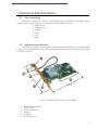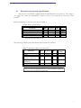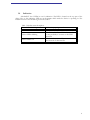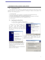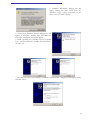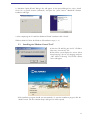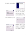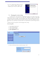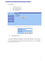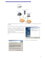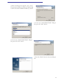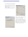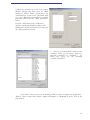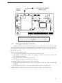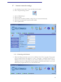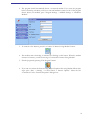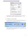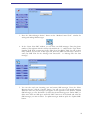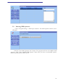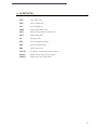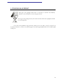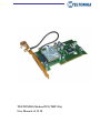
1
TELTONIKA ModemPCI (TMP-10x)
User Manual v2.1.1.18
TABLE OF CONTENTS
Table of contents..........................................................................................................................................2
Attention! .......................................................................................................................................................3
Legal notice....................................................................................................................................................3
Introduction ..................................................................................................................................................4
1.
Package contents...............................................................................................................................5
2.
Technical specifications ...................................................................................................................6
2.1
Data transferring ..........................................................................................................................6
2.2
Mechanical specifications............................................................................................................6
1.3
Electrical and operating specifications......................................................................................7
1.4
Indication ......................................................................................................................................8
3.
Modem installation and setup.........................................................................................................9
3.1
Connecting to a PC......................................................................................................................9
3.2
Installing the modem driver .......................................................................................................9
3.3
Installing the “Modem Control Tool”................................................................................... 11
3.4
Changing the security settings................................................................................................. 13
3.5
Controlling a server .................................................................................................................. 14
3.6
Setting up an Internet connection .......................................................................................... 19
3.7
Internet connection settings .................................................................................................... 20
3.7.1
Connecting to the Internet ............................................................................................. 20
3.8
Sending Short Text Messages (SMS)...................................................................................... 22
3.9
Selecting GSM operators ......................................................................................................... 24
4.
Acronyms........................................................................................................................................ 25
5.
Technical support .......................................................................................................................... 26
2
ATTENTION!
Do not disassemble the device.
All wireless devices for data transferring are susceptible to
interference, which could affect performance.
Only qualified personnel may install or repair this product.
Your device is not water-resistant. Keep it dry.
LEGAL NOTICE
Copyright © 2006 TELTONIKA Ltd.
All rights reserved. Reproduction, transfer, distribution or storage of part or all of the contents in this
document in any form without the prior written permission of TELTONIKA Ltd is prohibited.
Other product and company names mentioned herein may be trademarks or trade names of their
respective owners.
3
INTRODUCTION
In this document, you will find a detailed description how to install and to use the
“ModemPCI” modem as well as software to operate it.
“ModemPCI” is a device designed for data transmission via GSM Network. The Modem is
designed to be mounted into the motherboard of a PC. Once the device is mounted into the
motherboard you can access the Internet and send SMS messages. “ModemPCI” supports the
following data-bearers: EDGE, GPRS, CSD, CSF, HSCSD, and SMS. The device can function as a
“watchdog” timer, watching over the PC temperature and van velocity.
4
1. PACKAGE CONTENTS
“ModemPCI” is supplied to clients in a cardboard box with all of the contents, which are
needed for the connection to a PC and operation of the device.
1) Cardboard box.
2) “ModemPCI” modem.
3) CD with User’s Guide and drivers.
4) External GSM antenna (special orders only).
5) “Reset” cable.
Notice: The manufacturer does not supply the SIM card, which is mandatory for setting up a
connection to the GSM network! The SIM card may be purchased from your GSM service supplier!
If any of the components is missing please contact your local distributor. The position of the
modem usage has no influence on safety.
5
2. TECHNICAL SPECIFICATIONS
2.1
Data transferring
“ModemPCI” supports these bearers of the GSM Network. It depends on the GSM operator
and data transfer capacity in the chosen GSM Network, which data type is used.
• EDGE 6 class.
• GPRS 10 class.
• HSCSD.
• CSD.
• CSF.
• SMS.
2.2
Mechanical specifications
“ModemPCI” modem is a board, which is mounted into the motherboard of a PC. The modem
is connected to the motherboard using a PCI connector. External dimensions and measures of the unit
are shown in picture 1.
6
21.7
1
2
5
121
3
4
119.9
1 Pict. An external look and measures of the modem
1.
2.
3.
4.
5.
6.
External antenna adapter.
„Reset“ button.
Socket for SIM card.
Indicator.
PCI adapter.
Ground connector.
6
1.3
Electrical and operating specifications
The power for the modem is supplied from the Motherboard’s PCI connector. The voltage is
+5V
. A PC, which the “ModemPCI” modem is going to be connected to, must have a PCI
interface.
Electrical parameters of the device are shown in Table 1.
Table 1. Device specifications
Parameter
Min
Power supply Voltage
Average Power consumption
Maximum Power consumption 1
+5
1
Typical
Max
+5
2
10
Measr.
Units
V
W
W
Does not last more than 1.2 ms
The operating conditions and other characteristics are shown in Table 2.
Table 2. Operating conditions and other data.
Parameter
Weight
Recommended
operating temperature
Marginal operating
temperature
Storage temperature
Min
Nominal
Max
100±5
+25
Measr.
Units
g
ºC
-25
+35
ºC
-40
+85
ºC
Notice: The device may malfunction in the case if the environment conditions do
not conform to those provided in this paragraph!
7
1.4
Indication
“ModemPCI” has 2 LEDs in one for indication. The LED is located on the top part of the
device. Due to this indicating LED we can determine which mode the device is operating in. The
indication status of the modem is given in the Table 3.
Table 3. Modem status description.
Green LED is blinking
Green LED is on
Yellow LED is blinking
Yellow LED is on
Modem is preparing to work
The device is ready to use
No SIM card inside, no PIN code entered
or any possibility to connect to the GSM
Network
The device has successfully connected to
the Network for data transfer
8
3. MODEM INSTALLATION AND SETUP
3.1
Connecting to a PC
The “ModemPCI” device and all of its components can be connected to the PC only by a person
qualified for this job, who will be responsible for connecting the modem and the quality of the
connection. The connecting steps are:
1)
2)
3)
4)
5)
6)
3.2
Turn Off your PC.
Insert SIM card into the mode. Make sure, the SIM card is pushed inside till it fixes.
Mount the “ModemPCI” modem into the Motherboard of a PC.
Ground by fixing “ModemPCI” with gudgeon (4mm diameter) with spacer to PC block.
Connect an external GSM antenna to the “ModemPCI” board.
Turn on the PC.
Installing the modem driver
Turn your PC on and wait until the OS boots.
Insert the CD supplied in the cardboard package into CD ROM.
1. “Windows XP” OS will automatically detect a
new device “PCI Simple Communications
Controller”. “Found New Hardware Wizard”
dialogue box will appear. In the opened dialogue
box, select “No, not this time” and press the
“Next” button.
2. “Found New Hardware Wizard” dialogue box
will appear. In the opened dialogue box, select
„Install from a list or specific location (Advanced)“
and press the “Next” button.
3. “Found New Hardware Wizard” dialogue box
will appear. In the opened dialogue box, select
“Include this location in the search” where the
installation files are
(\Drivers\ModemPCI\Windows\ WindowsXP)
and press the “Next” button”.
9
4. “Hardware Installation” dialogue box will
appear. Stating that there hasn’t been any
“Windows Logo” testing performed for the
driver, select “Continue Anyway”.
5. “Found New Hardware Wizard” dialogue box will
appear. A successful „NetMos 9835 PCI Multi-I/O
Controller” installation message will appear;
6. Install a parallel port (“NetMos PCI ECP Parallel
Port”) and two serial ports (“NetMos PCI Serial Port”)
the same way.
7. After the ports have been installed, a “Hardware Update Wizard” dialogue box will appear. Select
and click “Next”.
10
8. “Hardware Update Wizard” dialogue box will appear. In the opened dialogue box, select „Install
from a list or specific location (Advanced)“ and press the „Next“ button. “ModemPCI modem
installation will begin.
9. After completing the “Found New Hardware Wizard” installation click “Finish”.
Windows 2000 OS: follow the Windows XP installation steps (1 – 9).
3.3
Installing the “Modem Control Tool”
1. Take the CD and Plug into the PC CD Drive.
Then start “Autorun.exe” file.
2. Wait till the system displays the screen “Select
Setup Language” choose your language and press
„OK“ button. Following TELTONIKA Home
screen will appear;
3. The installation program should start automatically. To start the installation progress click the
“Install” button. The first “Modem Setup” dialogue box will be opened;
11
4. Press the “Next” button in the opened box. A
second “Modem Setup” dialogue box will appear;
5. You can select a preferable driver installation
way in the dialogue box. When “Typical”
installation is chosen, a standard driver will be
installed. When “Custom” installation is
chosen, you can install separate driver
components and view the driver installation
folder. When “Complete” installation is
selected, a complete driver installation will take
place. It is recommended to select a “Custom”
installation. The third “Modem Setup” dialogue
box will be opened;
6. “Modem Setup” dialogue box will appear.
Press “Install” in the opened dialogue;
7. “Modem Setup” dialogue box will appear.
Enter the dial-up settings in the dialogue box.
The dial-up settings are automatically read from
a *.ini file on the CD. Should the parameter
fields appear empty, the user has to fill them in
by him self. He can obtain the dial-up settings
from his GSM operator. When all of the
necessary fields have been filled, click the
“Next” button;
12
8. A new „Modem Setup “dialogue box will
state a successful „Modem Control Tool“
installation process. Press the „Finish” button.
3.4
Changing the security settings
For SIM security, a unique PIN (Personal Identification Number) is used. Before starting using
GSM network services, it is necessary to enter a PIN code. “ModemPCI” supports two main GSM
security modes: “PIN code enabled”, “PIN code disabled”. When “PIN code enabled” mode is chosen,
the PIN code will be requested each time the modem is turned on. If the mode „Disabled“ is chosen,
PIN code has to be entered just once and this will not be required further on when turning the device
on.
“Modem Control Tool” program is used for changing security settings.
Deactivating PIN:
1)
2)
3)
4)
5)
Start “Modem Control Tool”.
Select “Program Settings”.
Select “Security Settings”.
Select “PIN Request Disable”.
Press “Update Date”.
6) Enter your PIN code in the new window and press “OK”.
13
Activating PIN:
3.5
1)
2)
3)
4)
5)
Start “Modem Control Tool”.
Select “Program Settings”.
Select “Security Settings”.
Select “PIN Request Enable”.
Press “Update Data”.
6)
Enter your PIN code in the new window and press “OK”.
Controlling a server
“ModemPCI” modem could be applied as a “watchdog” timer and restart a server, should it not
respond within a predefined time. “ModemPCI” provides an additional Internet connection channel
for servers. System administrators could use this safe connection channel for server configuration.
Also you can control a COM port of a server directly from your PC. It also gives you the possibility
to send SMS messages from your PC.
14
The administrator himself can restart a server. In order to make these following steps should be
performed:
First you have to install a Nokia 12 Configuration driver, instructions on how to do this below:
1) Click the “Nokia 12 Configurator” driver
installation file “Nokia12Configurator2_62.exe”
on the CD “Drivers” catalogue. Once the file has
been started, the first “Install Shield Wizard”
dialogue box will appear.
2) Press the “Next” button in the opened dialogue
box.
3) Press “Yes” in the new dialogue box.
15
4) When the dialogue box appears, press “Next”.
If you press the “Browse” button, you will be able
to choose the driver installation folder by yourself.
5) In the next “Install Shield Wizard” dialogue
box, press the “Next” button.
6) In the next “Install Shield Wizard” dialogue
box, press the “Next” button.
7) Press the “Finish” button in the new dialogue
box.
16
How to configure the “Nokia 12 Configurator”?
1) Start the “Nokia 12 Configurator”. Select
“File/Module Configuration” in the main
configuration window. A “Module Configuration”
dialogue box will appear.
2) Press the “Read parameters” button and select
“General IO” and then press “Write parameters”.
3) Select “User Control Module” in the main
window of “Nokia 12 Configurator”. “User
Control Module” window will appear.
4) Press the “Read parameters” button on the
“Initialize” tab in the opened window. Once this
has been done, “Identifier” identification name
(f.e. “opa”) will show up in the “Message
Identifier” field. You can change this
identification name by clicking on the “Change”
button. Press the “Write parameters” button, then
a new identification name will be entered;
17
5) Select the “Security” tab in the “User Control
Module” dialogue box. Then press the “Read
parameters” button. Enter a password in the
“Authentication” section in the “Password” field
(f. e. “opa”). Retype the password in the “Confirm
password” field. Press the “Write parameters”
button.
Press the “Add” button in the “Authorized
number” section and add phone number of the
administrator that will control the server and press
the “Write parameters” button.
7) In the “User Control Mode” window, in the
“Aliasing” section you can create a name of a
rebooting command (f.e. “Perkrauti”).
To
reboot the server, use the command
“OUTPUT_INVER 7”.
If you want to reboot your server by sending an SMS, you have to connect two special wires “Reboot” cable to main board “Reset” adapter and adapter of “ModemPCI” device. Look at the
picture below.
18
Before connecting or disconnecting this “Reboot” cable you have
to turn off your PC and disconnect it from the power supply
network!!
3.6
Setting up an Internet connection
Before connecting to the Internet we recommend you to consult with your local GSM provider.
They should provide you with the detailed information regarding the Internet settings of your device.
In this chapter we will provide you with general information on how to prepare and set up your PC for
the Internet connection.
Before you proceed, make sure that:
• You have got a GSM SIM card with activated data transferring service.
• “ModemPCI” is ready to work – SIM card is pushed in, the device is properly connected to the
PC, the drivers are installed.
• Dial-up networking is installed on your PC (OS).
• TCP/IP protocol support is installed on your PC (OS).
“ModemPCI” supports two different types of data transferring:
• GPRS/EDGE packet data transfer. In this case you have to know the APN, user name and
password.
• CSD/HSCSD data transfer. You have to know the phone number of a dial-up server.
If GPRS/EDGE for data transfer is used, you have to set up an APN (Access Point Name)
19
3.7
Internet connection settings
1) Start “Modem Control Tool”. Enter the PIN code if needed.
2) Press “Program Settings” button.
3)
4)
5)
6)
7)
Select “GPRS Settings”.
Enter the APN.
Enter the ISP and Phone number [*99#], if they not entered automatically.
Enter the User name and User password if needed.
Press “Update Data”.
3.7.1
Connecting to the Internet
1. When the dial-up connection is set start the “Modem Control Tool” program. The program
can be started from the PC desktop (or “Start → Programs → Modem Control Tool →
Modem Control Tool”) by clicking on the shortcut. When the shortcut will is clicked,
“Modem Control Tool” dialogue box will be opened. If the PIN control code is set on your
SIM card, the program will ask you to enter the PIN code.
20
2. The program should automatically detect a connected modem. If you start the program
before connecting a modem, you have to wait until modem is ready to work. If the program
doesn’t detect your modem, press “Program Settings → Modem Settings → Autodetect
Modem”.
3. To connect to the Internet, press the “Connect To Internet Using Modem” button:
4. The modem starts connecting to Internet after clicking on this button. When the modem
connects to Internet, you will see message “Connected To Internet Using Modem”.
5. Exit the program by pressing “Exit Program” button:
6. If you can not connect the Internet using Internet Explorer after using Modem follow these
steps: press “Start → Settings → Control Panel → Internet Options”. Select the box
“Connections” in the “Internet Properties” dialogue box.
21
7. Select the dial-up icon in the “Dial-up and Virtual Private Network settings” field and press
the “Set Default” button, then chose “Always dial my default connection” and press the
“Apply” and “OK “ buttons. Now try to connect to the Internet again.
3.8
Sending Short Text Messages (SMS)
1. It is possible to send and receive short text messages (SMS) using “ModemPCI”. Before using
that “ModemPCI” function it is obligatory to disconnect from the Internet. This can be
performed by clicking on the “Disconnect From Internet” button;
2. Before sending SMS messages you have to check the number of messages sending center.
Press “Program Settings” and “SMS Settings”. The number of messages sending center
should be entered in the window of “SMS Settings”. If not, enter it manually. You can ask
your GSM operators for this number;
22
3. Press the “Short Messages Service” button on the “Modem Control Tool” window for
writing and reading SMS messages:
4. In the “Create New SMS” window, you can write your SMS messages. Enter the phone
number of the recipient with the country code without the “+” symbol in the “Type Phone
Number” field. Write your message in the “Place Your Text Below” field. You can see how
many symbols you have left on the right side, above the SMS text field. Press “Send” to
send your SMS. Wait for the “Message Sent Successful” or “Message Was Not Sent
message”;
5. You can also read your incoming, sent and unsent SMS messages. Press the “Short
Messages Service” and the “Unread” button. You will see a list of all unread messages.
When you select one, the message’s text appears on the right side of the window. All read
SMS messages go to the Read menu. To delete the selected message press “Delete SMS”, to
delete more than one SMS press and hold “Shift” button on the keyboard and select the
SMS messages you want to delete. To update messages windows press the “Update SMS“
button.
23
3.9
Selecting GSM operators
Choose “Program Settings → GSM Oper. Selection.” The GSM Operator Selection screen
will appear
Click the “Get GSM Operators List” button. The program will show all available GSM
operators. Click “Select Available GSM Operator” button after you choose your desirable operator
and the desirable operator will be chosen.
24
4. ACRONYMS
APN
Access Point Name
CSD
Circuit Switched Data
CSF
Circuit Switched Fax
GPRS
General Packet Radio Service
GSM
Global System for Mobile communications
LED
Light Emitting Diode
OS
Operating System
PIN
Personal Identification Number
SIM
Subscriber Identity Module
SMS
Short Message Service
TCP/IP
Transmission Control Protocol/Internet Protocol
EDGE
Enhanced Data rates for GSM Evolution
HSCSD
Height speed Circuit Switched Data
25
5. TECHNICAL SUPPORT
This sign on the package means that it is necessary to read the User Manual,
which is on the CD before you start using the device.
This sign on the package means, that used electronic and electric equipment should
be stored separately.
If you face some problems using the device, which you are not able to solve by yourself, you
are always welcome to contact our technical support by email: [email protected]. We would be glad
to help you.
26