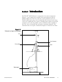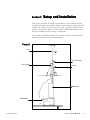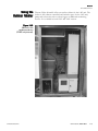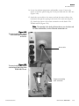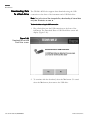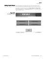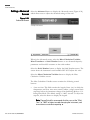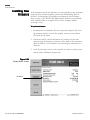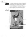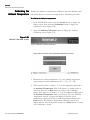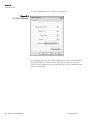
1
TEOM® 1405-D:
Dichotomous Ambient Particulate Monitor
42-010977
Revision A.000 15Feb2008
This documentation contains trade secrets and confidential information proprietary to Thermo Fisher Scientific.
The software supplied with the instrumentation, documentation and any information contained therein may not
be used, duplicated or disclosed to anyone, in whole or in part, other than as authorized in a fully executed
Thermo Fisher Scientific End User License Agreement or with the express written permission of Thermo Fisher
Scientific.
© 2007 Thermo Fisher Scientific. All rights reserved.
TEOM®, is registered trademarks of Thermo Fisher Scientific. Other trademarks are the property of their
respective holders.
Mention of specific product names (other than Thermo Fisher Scientific products) in this manual does not
constitute an endorsement or recommendation by Thermo Fisher Scientific of that equipment.
Warranty
Seller warrants that the Products will operate substantially in conformance with Seller’s published
specifications, when subjected to normal, proper and intended usage by properly trained personnel, for 12
months from date of installation or 13 months from date of shipment, whichever is less (the “Warranty Period”).
Seller agrees during the Warranty Period, provided it is promptly notified in writing upon the discovery of any
defect and further provided that all costs of returning the defective Products to Seller are pre-paid by Buyer, to
repair or replace, at Seller’s option, defective Products so as to cause the same to operate in substantial
conformance with said specifications. Replacement parts may be new or refurbished, at the election of Seller.
All replaced parts shall become the property of Seller. Shipment to Buyer of repaired or replacement Products
shall be made in accordance with the provisions of Section 5 of the Terms and Conditions of Sale agreement.
Lamps, fuses, bulbs and other expendable items, including the dryers, are expressly excluded from the warranty
under Section 9 of the Terms and Conditions of Sale agreement. Seller’s sole liability with respect to equipment,
materials, parts or software furnished to Seller by third party suppliers shall be limited to the assignment by
Seller to Buyer of any such third party supplier’s warranty, to the extent the same is assignable. In no event shall
Seller have any obligation to make repairs, replacements or corrections required, in whole or in part, as the
result of (i) normal wear and tear, (ii) accident, disaster or event of force majeure, (iii) misuse, fault or
negligence of or by Buyer, (iv) use of the Products in a manner for which they were not designed, (v) causes
external to the Products such as, but not limited to, power failure or electrical power surges, (vi) improper
storage of the Products or (vii) use of the Products in combination with equipment or software not supplied by
Seller. If Seller determines that Products for which Buyer has requested warranty services are not covered by the
warranty hereunder, Buyer shall pay or reimburse Seller for all costs of investigating and responding to such
request at Seller’s then prevailing time and materials rates. If Seller provides repair services or replacement parts
that are not covered by the warranty provided in Section 9 of the Terms and Conditions of Sale agreement.,
Buyer shall pay Seller therefore at Seller’s then prevailing time and materials rates. With respect to spare parts,
the above-referenced warranty applies, however, such warranty is limited to ninety (90) days from the date of
shipment.
ANY INSTALLATION, MAINTENANCE, REPAIR, SERVICE, RELOCATION OR ALTERATION TO
OR OF, OR OTHER TAMPERING WITH, THE PRODUCTS PERFORMED BY ANY PERSON OR
ENTITY OTHER THAN SELLER WITHOUT SELLER’S PRIOR WRITTEN APPROVAL, OR ANY USE
OF REPLACEMENT PARTS NOT SUPPLIED BY SELLER, SHALL IMMEDIATELY VOID AND
CANCEL ALL WARRANTIES WITH RESPECT TO THE AFFECTED PRODUCTS. THE
OBLIGATIONS CREATED BY THIS SECTION TO REPAIR OR REPLACE A DEFECTIVE PRODUCT
SHALL BE THE SOLE REMEDY OF BUYER IN THE EVENT OF A DEFECTIVE PRODUCT.
EXCEPT AS EXPRESSLY PROVIDED IN THIS SECTION 9, SELLER DISCLAIMS ALL WARRANTIES,
WHETHER EXPRESS OR IMPLIED, ORAL OR WRITTEN, WITH RESPECT TO THE PRODUCTS,
INCLUDING WITHOUT LIMITATION ALL IMPLIED WARRANTIES OF MERCHANTABILITY OR
FITNESS FOR ANY PARTICULAR PURPOSE. SELLER DOES NOT WARRANT THAT THE
PRODUCTS ARE ERROR-FREE OR WILL ACCOMPLISH ANY PARTICULAR RESULT.
Safety Notice
Repair of instrumentation manufactured by Thermo Scientific should only be attempted by properly trained
service personnel, and should only be conducted in accordance with the Thermo Scientific system
documentation. Do not tamper with this hardware. High voltages may be present in all instrument enclosures.
Use established safety precautions when working with this instrument.
The seller cannot foresee all possible modes of operation in which the user may attempt to use this
instrumentation. The user assumes all liability associated with the use of this instrumentation. The seller further
disclaims any responsibility for consequential damages. Use of this product in any manner not intended by the
manufacturer will void the safety protection provided by the equipment, and may damage the equipment and
subject the user to injury.
Preface
Equipment Rating
The following information can be used to determine the power service
requirements of this product.
Line Voltage
440VA, 47-63 Hz
IMPORTANT. Disconnect the power cord from the power source
(output) while servicing the instrument to prevent electrical hazard. ▲
Environmental Ranges — The instrument and its sample pump must be
installed in a weather-sheltered location that is heated in the winter and air
conditioned in the summer.
Note. There may be hazardous line (wire) accessible inside the
enclosure. ▲
Installation Category — Category 11
FUSES
Ref Designation
Current Rating
Location
Main Fuse (2)
T, 4A, 250VAC
Input Module
F201
F, 5A, 250VAC
Power Distribution Board
F202
F, 4A, 250VAC
Power Distribution Board
F203
F, 1A, 250VAC
Power Distribution Board
F204
F, 2A, 250VAC
Power Distribution Board
F201-F206
F, 2A, 125VAC
Head Controller Board
F401-402
T, 6.3 250VAC
FDMS Board
VI OPERATING GUIDE, TEOM 1405-D
THERMO FISHER SCIENTIFIC
Preface
Electrical/Safety
Certifications
The product has been tested and has been documented to be in compliance
with the following U.S. and Canadian safety standards:
UL Standard 61010-1:2004 2nd Edition
CAN/CSA C22.2 No. 1010-1:2004 2nd Edition
Thermo Fisher Scientific certifies that this product operates in compliance
with the EC Directive 89/336/EEC in reference to electrical emissions
and immunity. Specifically, the equipment meets the requirements of EN
61326-1:1998 for Immunity and Emissions. In addition, the hardware has
been tested for personal or fire safety hazards in accordance with
EN61010-1:2001 (Safety) in fulfillment of EC Directive 73/23/EEC.
Disposal of the
Instrument
This product is required to comply with the European Union’s Waste
Electrical & Electronic Equipment (WEEE) Directive 2002/96/EC. It is
marked with the WEEE symbol.
Thermo Fisher Scientific has contracted with one or more recycling/
disposal companies in each EU Member State, and this product should be
disposed of or recycled through them. Further information on Thermo
Fisher Scientific’s compliance with these Directives, the recyclers in your
country, and information on Thermo Fisher Scientific products which may
assist the detection of substances subject to the RoHS Directive are
available at: www.thermo.com/WEEERoHS.
THERMO SCIENTIFIC
OPERATING GUIDE, TEOM 1405-D
VII
Preface
Service Information
When you purchase Thermo Scientific products, you can depend on quality
products and expert service. We know that your product’s performance is
critical to your business, and that you require it to deliver timely and
reliable data. We are dedicated to helping you realize a maximum value in
your technology investment by providing a high level of personal attention,
premium technical assistance, and fast reliable response. Thermo Scientific
offers a full suite of warranty and service contract programs designed to
meet your specific support needs and keep your instrumentation operating
at peak performance. Contact:
Thermo Scientific
27 Forge Parkway
Franklin, Ma 02038
www.thermo.com
Section
Revision List
As Thermo Scientific’s instrumentation changes, so do our operating
manuals. However, these changes may affect only one aspect of an
instrument, while leaving the instrument as a whole unchanged. To explain
these individual changes to our customers, Thermo Scientific will update
only those sections of its operating manuals that are affected by the
instrument updates or improvements.
To help our customers keep track of the changes to the 1405-DF monitor
and its operating guide, following is a list of the sections with their
respective revision numbers:
Section Number and Description
VIII OPERATING GUIDE, TEOM 1405-D
Revision Number
Section 1: Introduction
A.000
Section 2: Setup and Installation
A.000
Section 3: Basic Operation
A.000
Section 4: Screens and Settings
A.000
Section 5: Maintenance and Calibration Procedures
A.000
Appendix A: Troubleshooting
A.000
Appendix B: Serial Communication
A.000
THERMO SCIENTIFIC
Preface
Table of Contents
Section 1 Introduction .......................................................................................... 1-1
Overview of Manual ................................................................................... 1-3
Application Range ........................................................................................ 1-4
Theory of Operation ................................................................................... 1-5
Mass Transducer Operation........................................................................ 1-6
Mass Flow Controllers ................................................................................. 1-9
Section 2 Setup and Installation .......................................................................... 2-1
Installation Considerations ......................................................................... 2-2
Standard System Hardware ......................................................................... 2-3
Pump Connections ....................................................................................... 2-4
Adjusting the Flow Splitter ......................................................................... 2-6
Assembling the Tripod ................................................................................. 2-8
Installing the Inlet and Impactor ................................................................ 2-9
Applying Power to the Instrument .......................................................... 2-16
Restarting the Instrument ......................................................................... 2-18
Turning Off the Instrument ..................................................................... 2-18
Using the Outdoor Shelter ........................................................................ 2-19
Section 3 Basic Operation ................................................................................... 3-1
Starting the Instrument................................................................................ 3-2
Performing a Leak Check ............................................................................ 3-4
Storing Data .................................................................................................. 3-8
Downloading Data ..................................................................................... 3-10
Installing ePort ........................................................................................... 3-11
Connecting to the TEOM 1405-D Unit ................................................. 3-16
Finding Instruments On a Network ........................................................ 3-20
Setting Up for Manual Data Downloads ................................................ 3-22
Setting Up for Automatic Data Downloads .......................................... 3-24
Performing a Data Download .................................................................. 3-26
Downloading Data To a Flash Drive ...................................................... 3-28
Viewing Downloaded Data ...................................................................... 3-30
User I/O Connections ............................................................................... 3-31
USER I/O Pin Assignments .................................................................... 3-32
Section 4 Screens and Settings ........................................................................... 4-1
TEOM Data Screen ..................................................................................... 4-2
Operating Mode ............................................................................................ 4-6
System Status Screen ................................................................................... 4-8
Instrument Conditions Screen .................................................................. 4-10
Flows Screen ............................................................................................... 4-13
Flow Rates Screen ...................................................................................... 4-14
Flow Control Screen .................................................................................. 4-15
Instrument Temperatures Screen ............................................................. 4-18
Analog Inputs Screen ................................................................................. 4-19
THERMO SCIENTIFIC
OPERATING GUIDE, TEOM 1405-D
IX
Preface
Settings Screen ............................................................................................ 4-20
System Screen ............................................................................................. 4-22
Analog & Digital Outputs Screen ........................................................... 4-24
Analog Outputs Screen ............................................................................. 4-25
Contact Closure Screen ............................................................................. 4-26
RS232 Screen .............................................................................................. 4-27
Settings Advanced Screen ......................................................................... 4-28
Service Screen ............................................................................................. 4-30
Instrument Control Screen ........................................................................ 4-32
Service Advanced Screen.......................................................................... 4-33
Installing New Firmware ........................................................................... 4-34
Section 5 Maintenance and Calibration Procedures .......................................... 5-1
Periodic Maintenance .................................................................................. 5-1
Maintenance Wizards ................................................................................... 5-2
Filter Loading ................................................................................................ 5-4
TEOM Filter Replacement ......................................................................... 5-4
Changing the TEOM Filters ....................................................................... 5-6
Advanced Filter Change ............................................................................ 5-13
Conditioning the TEOM Filters .............................................................. 5-15
Cleaning the PM-10 Inlet .......................................................................... 5-16
Cleaning the Virtual Impactor .................................................................. 5-20
Exchanging In-Line Filters ........................................................................ 5-22
Cleaning the Air Inlet ................................................................................. 5-26
Audit/Calibration Procedures .................................................................. 5-28
Auditing the System ................................................................................... 5-31
Calibrating the Ambient Temperature .................................................... 5-32
Calibrating the Ambient Pressure ............................................................ 5-33
Auditing the Flow Rates............................................................................ 5-34
Calibrating the Flow Rates........................................................................ 5-40
Calibrating the Analog Outputs ............................................................... 5-46
Verifying the Calibration Constant .......................................................... 5-52
Appendix A Troubleshooting ................................................................................... A-1
Converting Decimal/Hexadecimal Numbers ......................................... A-3
Deciphering Status Codes .......................................................................... A-4
Example ........................................................................................................ A-4
Appendix B Serial Communication ......................................................................... B-1
AK Protocol .................................................................................................. B-1
X OPERATING GUIDE, TEOM 1405-D
THERMO SCIENTIFIC
Section 1
Introduction
The TEOM® 1405-D Monitor is composed of two major components
(Figure 1-1): the sample inlet assembly with virtual impactor and the
TEOM 1405-D unit. The user enters the system parameters into the
TEOM 1405-D unit using a color touchscreen that is located on the front
of the unit. Additionally, the system is furnished with software for personal
computers (a PC with an updated version of Windows XP is required) to
allow the user to download data and update instrument firmware. The
instrument does not require a dedicated computer to function in the field.
Figure 1-1.
Schematic of typical installation.
Inlet
Virtual impactor
Flow splitter
Tripod
TEOM 1405-D
THERMO FISHER SCIENTIFIC
OPERATING GUIDE, TEOM 1405-D
1-1
S ECTION 1
INTRODUCTION
The sensor unit contains the two mass measurement hardware systems that
monitor particles that continuously accumulate on the system’s
exchangeable TEOM filters. PM-Coarse and PM-2.5 particulate, split by a
virtual impactor, each accumulate on the system’s exchangeable TEOM
filters. By maintaining a flow rate of 1.67 l/min through the coarse sample
flow channel and 3 l/min through the PM-2.5 sample channel, and
measuring the total mass accumulated on each of the TEOM filters, the
device can calculate the mass concentration of both the PM-2.5 and PMCoarse sample streams in near real-time.
1-2 OPERATING GUIDE, TEOM 1405-D
THERMO FISHER SCIENTIFIC
S ECTION 1
INTRODUCTION
Overview of Manual
This manual describes the installation and operation of the TEOM 1405-D
Monitor. Follow the setup instructions contained in Section 2 and before
attempting to operate the unit.
This manual is divided into five sections. Sections 1 and 2 explain the
system’s hardware, while later sections describe the system’s software and
the setup and operation of the monitor. The following list provides an
overview of the topics handled in each section of the manual:
Section 1: Introduction
This section provides an overview of the TEOM 1405-D Monitor, as well
as the theory of operation of the instrument’s mass transducer.
Section 2: Setup and Installation
This section describes how to set up and install the system’s hardware and
sampling system.
Section 3: Basic Operation
This section provides instructions on how to turn on the instrument and
initiate a sampling run. It also explains how to download data and how to
leak check the instrument.
Section 4: Screens and Settings
This section explains how to set up the instrument’s firmware and its
operating modes.
Section 5: Maintenance and Calibration Procedures
This section describes the routine maintenance and verification procedures
for the TEOM 1405-D Monitor.
Appendix A: Troubleshooting
Appendix includes the information on deciphering status codes and as well
as key schematics for troubleshooting purposes.
Appendix B: Serial Communication
This appendix includes information on the instrument’s program register
codes and built-in AK protocol.
THERMO FISHER SCIENTIFIC
OPERATING GUIDE, TEOM 1405-D
1-3
S ECTION 1
INTRODUCTION
Application Range
The TEOM 1405-D Monitor is a real-time device used for measuring the
particulate matter mass concentration of particulate matter of both PMCoarse and PM-2.5.
TEOM instruments are the only filter-based mass monitors that measure
the mass of particulate matter suspended in gas streams in real time. This is
made possible through the use of an inertial mass transducer patented in
the U.S. and internationally by Thermo Scientific.
The monitor is ideally suited for applications demanding real-time air
particulate matter monitoring in outdoor, indoor or industrial settings. It
calculates mass concentration, mass rate and the total mass accumulation
on the TEOM filter under the following conditions:
Flow rate through sample inlet
PM-2.5 flow rate
PM-Coarse flow rate
Temperature of sample stream
Particulate matter mass concentration
1-4 OPERATING GUIDE, TEOM 1405-D
16.7 l/min (1 m3/hr)
3 l/min
1.67 l/min
30º C
less than 5 µg/m3 to several
g/m3
THERMO FISHER SCIENTIFIC
S ECTION 1
INTRODUCTION
Theory of Operation
The TEOM 1405-D Monitor is a true “gravimetric” instrument that draws
(then heats) ambient air through two filters at constant flow rate,
continuously weighing the filter and calculating near real-time mass
concentrations of both PM-2.5and PM-Coarse particulate matter. In
addition, the instrument computes the 1-hour, 8-hour, 12-hour and 24-hour
averages of the mass concentration for both types of particulate.
Analog outputs are available to transmit the measurements to a user’s data
acquisition system. An RS232 port allows for serial communication. The
instrument’s internal storage buffer can store a large amount of data for
later viewing or downloading over a network connection. A USB
connection allows easy downloads to a portable USB flash drive.
THERMO FISHER SCIENTIFIC
OPERATING GUIDE, TEOM 1405-D
1-5
S ECTION 1
INTRODUCTION
Mass TTransducer
ransducer
Operation
The weighing principle used in the the tapered element oscillating
microbalance (TEOM) mass transducers (Figure 1-2) is similar to that of a
laboratory microbalance in that the mass change detected by the sensor is
the result of the measurement of a change in a parameter (in this case,
frequency) that is directly coupled via a physical law (or from first
principles).
Figure 1-2.
Schematic of mass transducer.
1-6 OPERATING GUIDE, TEOM 1405-D
THERMO FISHER SCIENTIFIC
S ECTION 1
INTRODUCTION
The tapered element at the heart of the mass detection system is a hollow
tube, clamped on one end and free to oscillate at the other. An
exchangeable TEOM filter cartridge is placed over the tip of the free end.
The sample stream is drawn through this filter, and then down the tapered
element. This flow is maintained at a constant volume by a mass flow
controller that is corrected for local temperature and barometric pressure.
The tapered element oscillates precisely at its natural frequency, much like
the tine of a tuning fork. An electronic control circuit senses this oscillation
and, through positive feedback, adds sufficient energy to the system to
overcome losses. An automatic gain control circuit maintains the
oscillation at a constant amplitude. A precision electronic counter
measures the oscillation frequency with a 10-second sampling period.
The tapered element is, in essence, a hollow cantilever beam with an
associated spring rate and mass. As in any spring-mass system, if additional
mass is added, the frequency of the oscillation decreases. This can be seen
by observing the frequency on the display of the TEOM 1405-DF unit
(Section 4), and operating the monitor both with and without a filter in
place.
In a spring-mass system the frequency follows the equation:
f = (K / M)0.5
where:
f =
K =
M =
frequency
spring rate
mass
K and M are in consistent units. The relationship between mass and change
in frequency can be expressed as:
dm = K 0
1
1
2 −
2
f1
f0
where:
dm =
K0 =
f0 =
f1 =
THERMO FISHER SCIENTIFIC
change in mass
spring constant (including mass conversions)
initial frequency (Hz)
final frequency (Hz)
OPERATING GUIDE, TEOM 1405-D
1-7
S ECTION 1
INTRODUCTION
When this equation is rearranged, you can solve for the spring constant, K0:
K0 =
dm
1
1
− 2
2
f1
f0
Thus, K0 (the calibration constant for the instrument) can be easily
determined by measuring the frequencies with and without a known mass
(pre-weighed TEOM filter cartridge).
1-8 OPERATING GUIDE, TEOM 1405-D
THERMO FISHER SCIENTIFIC
S ECTION 1
INTRODUCTION
Mass Flow
Controllers
The mass flow controllers (MFCs) in the TEOM 1405-D Monitor are
internally calibrated for a standard temperature and pressure of 25° C and 1
Atmosphere (1013.2 millibars or 760 mm Hg). For passive flow control, the
user must enter the seasonal average temperature (Ave. Temp.) and
average barometric pressure (Ave. Pres.) at the measurement site to allow
the instrument to sample at the correct volumetric flow rate (Section 4).
The microprocessor calculates the correct mass flow set point
(Flow_RateSTP) with this information using the following formula:
FlowSPPassive = FlowSPVol ×
PAVG Temp STD + 273.15
×
PSTD Temp AVG + 273.15
where:
FlowSPPASSIVE =
Control set point to mass flow controller (equivalent
flow at 25° C and 1 Atmosphere)
FlowSPVol
=
Volumetric flow rate set point (l/min)
TempAVG
=
Average temperature entered by the user (°C)
TempSTD
=
Standard temperature (25°C)
PAVG
=
Seasonal average barometric pressure entered by the
user (Atmospheres, where 1 Atmosphere = 1013.2
millibars or 760 mm Hg)
PSTD
=
Standard pressure (1 Atm)
Alternately, Active flow control can be set up to automatically measure the
ambient temperature and pressure using the hardware supplied.
Note. When using actual conditions for active volumetric flow control,
substitute the actual (local) temperature and pressure as measured by the
instrument for the average temperature and pressure variables in
equation above. ▲
THERMO FISHER SCIENTIFIC
OPERATING GUIDE, TEOM 1405-D
1-9
S ECTION 1
INTRODUCTION
PM-10 mass concentration data reported to the U.S. EPA must be
referenced to standard cubic meters of air based on a standard temperature
and pressure of 25° C and 1 Atmosphere (atm), respectively. For the
instrument to report mass concentrations according to this EPA standard,
the user must ensure that the standard temperature (Std. Temp.) and
standard pressure (Std. Pres.) entered in the instrument equal 25° C and 1
Atmosphere (Section 4). These are the default values for the instrument.
Flow_RateEPA = Flow_RateSTP ×
Std. Temp. + 273.15
1 atm
×
273.15
Std. Pres.
The flow rates referenced internally by the instrument to 0° C are
converted to EPA standard conditions.
Note. When reporting concentrations to actual conditions, the system
must be set for “Active” flow control (Section 4). This will ensure that the
monitor uses the current actual values for temperature and pressure in
the equation above. ▲
1-10 OPERATING GUIDE, TEOM 1405-D
THERMO FISHER SCIENTIFIC
Section 2
Setup and Installation
This section describes the setup and installation of the TEOM 1405-D,
including the pump, flow splitter, tripod, virtual impactor, sample tube and
sample inlet. After you have set up the system, you must perform a leak
check on the monitor (Section 3) and install a TEOM filter (Section 5) in
the mass transducer before starting a sample run.
If you want to install the monitor in an outdoor location, consult Thermo
Scientific for specific site recommendations.
Figure 2-1.
1405-D.
Inlet
Virtual impactor
Flow splitter
Tripod
FDMS tower
TEOM 1405-D
THERMO FISHER SCIENTIFIC
OPERATING GUIDE, TEOM 1405-D
2-1
S ECTION 2
SETUP AND INSTALLATION
Installation
Considerations
The TEOM 1405-D may be located in any convenient indoor location
which is maintained between 8° and 25° C (46° to 77° F). The user must
run two sampling tubes through the roof of the monitoring site (refer to the
inlet installation instructions later in this section). The entrance to the
sample inlet must be 1.8 to 2.1 m (70 to 82 inches) above the roof.
Although the TEOM monitor is inherently rugged, it is a precision
instrument. The user will obtain the best operating conditions and longest
instrument life when the unit is not exposed to extremes of weather. Filter
exchange, in particular, may be best accomplished by a technician
operating in an indoor environment where there is no possibility of rain or
snow contaminating the filter.
Be sure to install the ambient temperature/humidity sensor. If you do not
install the ambient temperature/humidity sensor, you must set the
instrument to “Passive” flow control (Section 4) or the mass flow
controller will attempt to control the sample flow as if the ambient
temperature is absolute zero.
The sample lines for the PM-2.5 and PM-Coarse channels should proceed
in a straight, vertical line from the PM-10 inlet and virtual impactor to the
inlet of the unit.
To achieve the best results, locate the TEOM sensor unit in an
environment with relatively slow temperature fluctuations. Avoid sampling
locations with direct exposure to sunlight or that are in close proximity to a
heating or air-conditioning outlet. To avoid condensation in the sample
tubing, Thermo Scientific strongly recommends that the user insulate the
sample tube extensions with pipe insulation when operating the instrument
in areas of high humidity.
2-2 OPERATING GUIDE, TEOM 1405-D
THERMO FISHER SCIENTIFIC
S ECTION 2
SETUP AND INSTALLATION
Standard System
Hardware
THERMO FISHER SCIENTIFIC
The TEOM 1405-D Monitor is supplied with the following components:
1405-D TEOM unit
Temperature/humidity sensor and cable, 10 m
3/8" green tubing for bypass flow, 10 m
3/8" green tubing to pump, 5 m (16.5 ft)
5 Sample tubing extensions, 1 m (40")
1 Sample tubing extension, .79 m (31")
Box of 20 TEOM filter cartridges (Pallflex TX40)
Filter exchange tool
1 small filter element
1 large bypass filter element
Flow splitter
PM-10 inlet
Sample inlet tube
Virtual impactor
Water trap filter assembly
Flow audit adapter/leak check kit
Vacuum pump
2 Operating Manuals (one hard copy, one on CD)
Quick Start Guide
Pre-filter/silicone tubing
OPERATING GUIDE, TEOM 1405-D
2-3
S ECTION 2
SETUP AND INSTALLATION
Pump Connections
Follow these steps to attach the pump:
1. Locate and cut the piece of the 15m green tubing into two pieces —
one about (but not less than) 5m (the lengths may be precut). (The
typical setup has 5m of tubing for the pump and 10m for the bypass
line.)
2. Push the one end of the 5m pump tubing into the fitting on the vacuum
pump (Figure 2-2).
Figure 2-2.
Vacuum pump.
3. Install the other end of the 5m length of pump tubing into the pump
connection on the back of the TEOM 1405-D unit (Figure 2-3).
Figure 2-3.
Back of TEOM 1405-D unit
To water trap filter
Pump connection
Bypass filter
2-4 OPERATING GUIDE, TEOM 1405-D
THERMO FISHER SCIENTIFIC
S ECTION 2
SETUP AND INSTALLATION
4. Mount the water trap filter assembly near the 1405 unit (Figure 2-4).
Figure 2-4.
Water trap filter assembly.
Quick-connect fitting
Water trap filter
Note. Drain the water trap as needed. ▲
5. From the 10m length of tubing for the bypass line, cut a piece of tubing
long enough to reach from the water trap filter to the bypass filter on
the back of the 1405 unit (Figure 2-3 and 2-4). Install the tubing into
the quick-connect fittings on the water trap filter and bypass filter.
6. Insert one end of the remaining section of bypass tubing into the quickconnect fitting at the end of the coiled piece of tubing connected to the
water trap filter.
Note. The other end of the bypass tubing will be connected to the
bypass connection on the flow splitter when you assemble and
install the sample inlet and virtual impactor (following section). ▲
7. Select a location on the pump tubing to install the vacuum gauge. It
should allow the gauge to be easily monitored (Thermo Scientific
suggests a location about half a meter from where the tubing is installed
in the pump connection on the back of the unit.) Cut the tubing and
install the two ends into the quick-connect fittings on the vacuum
gauge.
Note. Thermo Scientific strongly recommends that you use the
vacuum pump provided with the unit. If you choose to install a
different pump, it must be oil-free and able to maintain a 21" Hg
vacuum at a flow of 16.67 l/min. ▲
THERMO FISHER SCIENTIFIC
OPERATING GUIDE, TEOM 1405-D
2-5
S ECTION 2
SETUP AND INSTALLATION
Adjusting the
Flow Splitter
An isokinetic flow splitter (Figures 2-5 and 2-6) is used in combination
with an automatic flow controller to divide the PM-2.5/bypass flow into
two components after the air stream passes through the size-selective inlet
and virtual impactor. The two sample flow components are the PM-2.5
flow (3 l/min) that flows to the PM-2.5 TEOM mass transducer, and the
bypass flow (12 l/min). The PM-Coarse flow (1.67 l/min) moves in a
straight line through the virtual impactor into the top of the 1405-D.
The 1405-D is designed to have the sample tube installed 6-inches from
the top of the flow splitter for ease of installation. It MUST be between
5.75 and 6.25 inches from the top of the flow splitter.
Figure 2-5.
Flow splitter.
2-6 OPERATING GUIDE, TEOM 1405-D
THERMO FISHER SCIENTIFIC
S ECTION 2
SETUP AND INSTALLATION
The shorter length (31-inch) sample tube must be installed into the flow
splitter.
To set up the flow splitter assembly:
1. Locate the flow splitter (Figures 2-5 and 2-6).
2. Loosen the 1/2-inch sample tube fastener nut and slide the short (31inch) sample tube down into the flow splitter so that the top of the
installed sample tube (or flow adapter) is 15.5 cm (6") from the top of
the flow splitter (it must be between 5.75 and 6.25 inches from the top
of the flow splitter) (Figure 2-7).
3. Tighten the 1/2-inch sample tube nut. Ensure that the top of the flow
adapter remains 6 inches from the top of the flow splitter (Figure 2-7).
Figure 2-6.
Bottom of the flow splitter.
Flow splitter
Bypass tube
1/2-inch sample tube nut
Sample tube
Figure 2-7.
Measuring the distance from the
top of the sample tube to the top
of the flow splitter.
THERMO FISHER SCIENTIFIC
OPERATING GUIDE, TEOM 1405-D
2-7
S ECTION 2
SETUP AND INSTALLATION
Assembling the
Tripod
An optional tripod is available for installation on the roof of a sampling
building.
To assemble the tripod:
1. Locate a tripod foot and pull off the rubber leg holder, if one is
attached.
2. Place one leg of the tripod onto the tripod foot.
3. Place a metal bracket over the rubber base of the tripod leg and into
the two slots on the tripod foot (Figure 2-8). Ensure that the bracket is
placed over the rubber base on the end of the tripod leg.
Figure 2-8.
Placing the metal bracket on the
tripod foot.
4. Insert a plain washer then a lock washer onto each threaded end of the
bracket, then install the nuts on the threaded ends of the bracket and
tighten them with a 3/8" (or adjustable) wrench.
Note. Hand-tighten both nuts on the bracket before tightening
them with the wrench to ensure that the bracket is positioned
properly on the tripod leg and tripod foot. ▲
5. Repeat steps 1 through 4 for each leg of the tripod.
2-8 OPERATING GUIDE, TEOM 1405-D
THERMO FISHER SCIENTIFIC
S ECTION 2
SETUP AND INSTALLATION
Installing the Inlet
and Impactor
To install the inlet and virtual impactor:
1. Set the 1405-D unit on a bench or other support directly below the
location of the inlet on the roof of the sampling structure (Figure 2-1).
In its finished state, the entrance to the sample inlet must be 1.8 to
2.1 m (70 to 82 inches) above the roof
2. Install the assembled flow splitter into the tripod and lightly tighten the
knob to ensure the flow splitter stays in place (Figure 2-9).
Figure 2-9.
Bottom of the flow splitter.
Flow splitter
Sample tube
THERMO FISHER SCIENTIFIC
OPERATING GUIDE, TEOM 1405-D
2-9
S ECTION 2
SETUP AND INSTALLATION
3. Measure and mark two points 1 3/4 inches on center on the roof
directly above the two 1/2-inch sample lines on the top of the
instrument.
Note. In this example, a hole was cut in the roof to
accommodate a 4-inch PVC pipe and seal. The cap of the PVC
pipe was then drilled to accommodate the sample lines. ▲
4. Drill the holes in the roof for the two 1/2-inch sample lines and
another hole for the 3/8-inch bypass line tubing. (The bypass tubing
may also be run through a window or other opening.)
Note. The holes for the 1/2-sample lines MUST BE DRILLED
1 3/4-INCHES ON CENTER directly above the sample lines on the
top of the instrument. ▲
5. Set the tripod on the roof above the 1405 unit and adjust the legs so
the top of the tripod is above the roof opening.
Figure 2-10.
Installing the sample tubes and
bypass line through the roof.
Flow splitter (with bypass)
Sample tube extensions
(1 3/4-inch centers)
2-10 OPERATING GUIDE, TEOM 1405-D
THERMO FISHER SCIENTIFIC
S ECTION 2
SETUP AND INSTALLATION
6. Install the virtual impactor on the top of the flow splitter (Figure 2-11).
7. Install one of the 1/2-inch sample tube extensions into the coarse
sample fitting on the virtual impactor. It must be fully seated into the
fitting.
Note. The coarse flow channel is the right channel as you face
the instrument, with the 1/2-inch Swagelok connection on the
bottom of the virtual impactor. The 1/2-inch sample tube will run
parallel to the PM-2.5/bypass channel of the flow splitter just next
to the tripod, and when attached should be even with the bottom
of the sample tube in the flow splitter. ▲
8. Install the sample inlet tube on the top of the virtual impactor (Figure
2-11).
Figure 2-11.
Virtual impactor and sample
inlet tube.
Sample inlet tube
Virtual impactor
Flow splitter
Coarse sample tube
THERMO FISHER SCIENTIFIC
OPERATING GUIDE, TEOM 1405-D
2-11
S ECTION 2
SETUP AND INSTALLATION
9. Set the inlet on top of the sample inlet tube and adjust the tripod so the
entrance to the sample inlet is 1.8 to 2.1 m (70 to 82 inches) above the
roof (Figure 2-12).
Note. This measurement may vary based on the inlet height
required by the local regulatory agency. ▲
Figure 2-12.
Inlet installed.
Inlet entrance
Inlet
1.8 to 2.1 m
above the
roof
Sample tube
2-12 OPERATING GUIDE, TEOM 1405-D
THERMO FISHER SCIENTIFIC
S ECTION 2
SETUP AND INSTALLATION
10. Center the tripod over the roof holes. Measure and cut the sample tube
extensions from the top of the instrument, making sure to clean and
deburr the cut ends of the sample tube extensions. Install them through
the roof and connect the left (PM-2.5 channel) sample tube to the flow
splitter sample tube and the right (PM-Coarse channel) sample tube to
the sample tube installed into the virtual impactor.
Note. The flow splitter and coarse sample tube extension should
be seated firmly into the bottom of the virtual impactor (Figure 213). ▲
Figure 2-13.
Coarse sample tube, flow splitter
and virtual impactor installed.
Sample tube extension
(coarse channel)
Flow splitter extension tube
(PM-2.5 channel)
THERMO FISHER SCIENTIFIC
OPERATING GUIDE, TEOM 1405-D
2-13
S ECTION 2
SETUP AND INSTALLATION
11. Connect the green bypass tubing attached to the back of the instrument
to the bypass fitting on the flow splitter using the 3/8-inch Swagelok
fitting (Figure 2-14).
Figure 2-14.
Bypass tubing and sample tubes
installed
Sample tube extension
(coarse channel)
Bypass connection
Flow splitter extension tube
(PM-2.5 channel)
2-14 OPERATING GUIDE, TEOM 1405-D
THERMO FISHER SCIENTIFIC
S ECTION 2
SETUP AND INSTALLATION
12. Locate the ambient temperature and humidity sensor. Connect the
sensor to the flow splitter using the U-bolt provided with the system
(Figure 2-15).
13. Attach the sensor cable to the sensor and run the sensor cable to the
instrument through an opening in the roof or through a window. Attach
the sensor to the sensor connection on the back of the TEOM 1405-D
unit (Figure 2-16).
14. Fasten the tripod feet to the roof. The length and type of fasteners
depends on the type of roof surface. The tripod feet also may be
attached to a pallet or 3/4" marine plywood, with the pallet or plywood
secured by concrete blocks or sand bags.
Figure 2-15.
Temperature/humidity sensor
installed on flow splitter.
Flow splitter
Temperature/humidity
sensor
U-bolt
Figure 2-16.
Temperature/humidity sensor
connection of the back of the
TEOM 1405-D unit.
Temperature/humidity
cable connection
THERMO FISHER SCIENTIFIC
OPERATING GUIDE, TEOM 1405-D
2-15
S ECTION 2
SETUP AND INSTALLATION
Applying Power
to the Instrument
The TEOM 1405-D unit accepts all voltage inputs between 85 and 240
volts AC. The unit should be connected to an appropriate, code-approved,
grounded electrical outlet for the sampler location. The connection should
be easily accessible. Contact a qualified electrician if there is doubt as to
whether the power service for the instrument is adequate.
To turn on the monitor:
1. Install an appropriate power cord into the universal power connection
on the back of the instrument at the appropriate voltage.
Note. DO NOT attempt to bypass the grounding requirements for
the unit. ▲
Figure 2-17.
Power connection
on back of unit.
2. Install the other end of the power cord into an appropriate, easily
accessible, grounded, code-approved electrical outlet.
Note. Contact a qualified electrician if there is doubt as to
whether the power service for the instrument is adequate. ▲
2-16 OPERATING GUIDE, TEOM 1405-D
THERMO FISHER SCIENTIFIC
S ECTION 2
SETUP AND INSTALLATION
3. Press the “POWER” switch on the front panel of the control unit
(Figure 2-18). The unit will begin its startup routine. After a few
moments, the Title screen will appear on the control unit’s display and
then the TEOM Data (Main) screen. Refer to Sections 3 and 4 for
information on the instrument’s software screens.
4. Plug the pump into an appropriate power source to draw a sample
stream through the system.
Figure 2-18.
Power switch.
Power switch
The TEOM Data screen will show a warning message (Section 4) because
the flow rates and temperatures are outside of tolerance ranges. The
warning may remain active during the first 30 minutes after the power
switch is pressed while the monitor warms up. The status warning icon
automatically disappears after all flow rates and temperatures reach
tolerance ranges. The monitor waits until the flow rates and temperatures
stabilize within a narrow range before starting data collection. This ensures
the validity of all data points computed by the system.
Note. Upon initial instrument start up, the values in the mass
concentration fields are the running averages that are accumulated until
a 1-hour time period has passed. The values are visible to provide the
user with an indication that the instrument is functioning, after instrument
power up or reset. These raw values are used for internal calculations
only. ▲
THERMO FISHER SCIENTIFIC
OPERATING GUIDE, TEOM 1405-D
2-17
S ECTION 2
SETUP AND INSTALLATION
Turning Off the
Instrument
If the instrument needs to be turned off, turn the power switch on the front
of the unit to off (0).
Note. Wait at least 1 minute after shutdown before reapplying power to
the unit.
The instrument may also be restarted without turning it off.
Restarting the
Instrument
To restart the instrument:
1. In the Service screen (Section 4), select the Instrument Control
button to display the Instrument Control screen (Figure 2-19).
2. Select the Reboot button.
Figure 2-19.
Instrument Control screen.
2-18 OPERATING GUIDE, TEOM 1405-D
THERMO FISHER SCIENTIFIC
S ECTION 2
SETUP AND INSTALLATION
Using the
Outdoor Shelter
Thermo Fisher Scientific offers an outdoor shelter for the 1405 unit. The
shelter is fully climate controlled and includes space for the 1405 unit,
pump and accessories such as a data logger or additional monitoring
devices. It is available in both 120V and 240V version.
Figure 2-20.
1405 unit in the
outdoor enclosure
(FDMS unit pictured).
THERMO FISHER SCIENTIFIC
OPERATING GUIDE, TEOM 1405-D
2-19
S ECTION 2
SETUP AND INSTALLATION
To install the 1405 unit in an outdoor shelter:
1. Before placing the 1405 unit or pump into the enclosure, install a 3/8inch elbow fitting provided with the outdoor enclosure into the quick
connect-fitting inside the pump compartment, where the pump tubing
goes through the bulkhead into the enclosure. Install the other 3/8-inch
elbows into the pump connection on the back of the 1405 unit and into
the connection on the pump (Figures 2-21, 2-22 and 2-23)).
Figure 2-21.
Enclosure.
Pump compartment
bulkhead connection
Figure 2-22 (left).
Back of the 1405 unit.
Pump connections
Figure 2-23 (right).
Pump.
2-20 OPERATING GUIDE, TEOM 1405-D
THERMO FISHER SCIENTIFIC
S ECTION 2
SETUP AND INSTALLATION
2. Install the water trap filter and bracket into the two pre-drilled holes on
the side of the pump compartment (Figure 2-24).
Figure 2-24.
Water trap filter.
Pump compartment
bulkhead connection
3. Cut a 14-inch (.35m) piece of tubing from the 3-foot section that came
with the enclosure package. Place the pump in the enclosure, and
connect the elbow fitting on the pump (Figure 2-23) to the elbow
fitting on the inside of the pump compartment using the 14-inch piece
of tubing.
4. Locate and cut the piece of the 15m green tubing, that came in the
1405 packaging, into two pieces — one about (but not less than) 5m.
5. Install the one end of the 5m pump tubing into the quick-connect
fitting on the outside bulkhead wall of the pump compartment (behind
the water trap filter, Figure 2-24).
6. Place the 1405 unit into the enclosure install the other end of the 5m
tubing that is connected to the bulkhead into the quick-connect elbow
fitting for the pump connection on the back of the 1405 unit (Figure 222).
THERMO FISHER SCIENTIFIC
OPERATING GUIDE, TEOM 1405-D
2-21
S ECTION 2
SETUP AND INSTALLATION
7. Select a location on the pump tubing to install the vacuum gauge. It
should allow the gauge to be easily monitored (Thermo Scientific
suggests a location about half a meter from where the tubing is installed
in the pump connection on the back of the unit.) Cut the tubing and
install the two ends into the quick-connect fittings on the vacuum
gauge.
8. From the 10m length of tubing for the bypass line, cut a piece of tubing
long enough to reach from the water trap filter to the bypass filter on
the back of the 1405 unit (Figure 2-22 and 2-24). Install the tubing into
the quick-connect fittings on the water trap filter and bypass filter.
Note. The bypass tubing will be connected to the bypass
connection on the flow splitter and to the water trap when you
assemble and install the sample inlet and virtual impactor on top
of the enclosure later in this section. ▲
9. Ensure that the shorter sample tube is properly installed in the flow
splitter (refer to “Adjusting the Flow Splitter” earlier in this section).
10. Install the sample tube from the flow splitter (PM 2.5 channel) through
the left, front roof opening (as you face the instrument). Install a
standard, 1m sample tube through the right, front fitting in the roof of
the enclosure (Figures 2-25 and 2-26).
Figure 2-25 (left).
Sample connections inside
enclosure.
Figure 2-26 (right).
Sample connections on top of
the enclosure.
PM 2.5 (short)
sample tube
Coarse (1m)
sample tube
2-22 OPERATING GUIDE, TEOM 1405-D
THERMO FISHER SCIENTIFIC
S ECTION 2
SETUP AND INSTALLATION
11. Install the adjustable elbow fitting and male swivel fitting from the
enclosure package onto the piece of 19-inch section of pipe that came
with the enclosure. Lightly tighten the screws. Install the elbow fitting
and support pipe onto the flow splitter and enclosure top (Figure 2-27).
Slide the support pipe up or down until the flow splitter is sitting
plumb, then attach the arm to the shelter and tighten all the screws on
Figure 2-27.
the support arm.
Support pipe connections.
Adjustable elbow
fitting
Flow splitter
Support pipe
Male swivel
fitting
THERMO FISHER SCIENTIFIC
OPERATING GUIDE, TEOM 1405-D
2-23
S ECTION 2
SETUP AND INSTALLATION
12. Install the virtual impactor on the top of the flow splitter and the
coarse sample fitting. The flow splitter and coarse sample tube must be
fully seated into the impactor (Figure 2-28).
Note. The coarse flow channel is the right channel as you face
the instrument, with the 1/2-inch Swagelok connection on the
bottom of the virtual impactor. ▲
Figure 2-28.
Virtual impactor,
temperature/humidity sensor
and sample tubes.
Virtual impactor
Temperature/humidity
sensor
Flow splitter
Coarse sample tube
Bypass connection
13. Cut a piece of tubing from the remaining section of bypass tubing (step
8) long enough to reach from the bypass connection to the top of the
1405 unit. The section should be long enough to include a loop (Figure
2-28) to ensure there will be no kinks in the line when it enters the
enclosure. Connect the bypass tubing to the bypass fitting on the flow
splitter using the 3/8-inch Swagelok fitting (Figure 2-28). Insert the
other end through the fitting on the roof (Figure 2-26) and into the
enclosure about 4 to 6 inches. Connect the coiled tubing from the
water trap filter to the bypass line near the top of the shelter with the
quick-connect fitting. Ensure that the coiled water trap tubing is
vertical (Figure 2-20).
2-24 OPERATING GUIDE, TEOM 1405-D
THERMO FISHER SCIENTIFIC
S ECTION 2
SETUP AND INSTALLATION
14. Locate the ambient temperature and humidity sensor. Connect the
sensor to the flow splitter using the U-bolt provided with the 1405 unit
(Figure 2-28).
15. Attach the sensor cable to the sensor and run the sensor cable to the
instrument through the opening in the back of the enclosure (Figure 229). Attach the sensor to the sensor connection on the back of the
TEOM 1405-D (Figure 2-30).
Note. The opening in the back of the enclosure can also be used
for other connections, such as Ethernet connections. ▲
Figure 2-29.
Temperature/humidity sensor
cable entering the outdoor
enclosure.
Sensor cable
Figure 2-30.
Temperature/humidity sensor
connection of the back of the
TEOM 1405-DF unit.
Temperature/humidity
cable connection
THERMO FISHER SCIENTIFIC
OPERATING GUIDE, TEOM 1405-D
2-25
S ECTION 2
SETUP AND INSTALLATION
16. Install the sample inlet tube on top of the virtual impactor. Install the
inlet (Figure 2-31).
Figure 2-31.
Outdoor enclosure with
inlet installed.
Inlet
Note. Drain the water trap as needed. ▲
Note. Thermo Scientific strongly recommends that you use the
vacuum pump provided with the unit. If you choose to install a
different pump, it must be oil-free and able to maintain a 21" Hg
vacuum at a flow of 16.67 l/min. ▲
2-26 OPERATING GUIDE, TEOM 1405-D
THERMO FISHER SCIENTIFIC
Section 3
Basic Operation
This sections describes the steps to begin data collection with the TEOM
1405-D monitor, as well as leak check the instrument and download data.
The instrument will not begin collecting data until the operating mode
message in the status bar reads “Fully Operational” (Figure 3-1). Users
must install clean, conditioned filters in the unit prior to sampling. Users
can select flow rate, data and other settings while waiting for the unit to
become fully operational.
Figure 3-1.
TEOM Data screen with
“Fully Operational” message.
Status bar
THERMO FISHER SCIENTIFIC
OPERATING GUIDE, TEOM 1405-D
3-1
S ECTION 3
BASIC OPERATION
Starting the
Instrument
To program the instrument and begin collecting data:
1. Perform a leak check (refer to the following section for leak check
information).
2. Install a TEOM filter into the mass transducer on both TEOMs
(Section 5).
3. When in the System Status screen, ensure that the serial number listed
for the instrument matches the serial number on the back of the unit.
4. When in the Instrument Conditions screen, select the Flows button to
display the Flows screen. Select the Flow Rates button to select the
desired flow rates for the PM-2.5, PM-Coarse and Bypass flow
channels. Select the Flow Control button to select the desired flow
control (“Active” or Passive”) and the desired standard and average
temperatures and pressures. (Refer to Section 4 for more information
on screens and settings.)
5. When in the Settings screen, select the System button, then the Set
Time button to set the current date and time. (Refer to Section 4 for
more information on screens and settings.)
6. When in the Settings screen, select the Advanced button, then the
Mass Transducer K0 Constants button to confirm the current K0
settings of the PM-2.5 and PM-Coarse TEOMs. The numbers
programmed into the unit must match the K0 constants on the label
near the mass transducer. (Refer to Section 4 for more information on
screens and settings.)
7. When in the Settings screen, select the Data Storage button to display
the Data Storage screen. Confirm the desired data is selected to be
logged by the instrument. (Refer to “Storing Data” later in this section
for more information on selecting storage variables.)
8. If you will be setting up the unit to receive an analog input, to transmit
analog outputs, or setting up the unit’s contact closure circuits, refer to
Section 4 for information on the screens and settings used for these
parameters.
3-2 OPERATING GUIDE, TEOM 1405-D
THERMO FISHER SCIENTIFIC
S ECTION 3
BASIC OPERATION
9. If you will be using the password function to control access to the
unit’s operation, refer to Section 4 for information on setting up the
password function.
10. Select the TEOM Data button to display the TEOM Data screen. The
instrument will begin collecting data when the mode status window
displays a “Fully operational” message.
Note. Upon initial instrument start up, the values in the mass
concentration fields are the running averages that are
accumulated until a 1-hour time period has passed. The values
are visible to provide the user with an indication that the
instrument is functioning, after instrument power up or reset.
These raw values are used for internal calculations only. ▲
THERMO FISHER SCIENTIFIC
OPERATING GUIDE, TEOM 1405-D
3-3
S ECTION 3
BASIC OPERATION
Performing a
Leak Check
The TEOM 1405-D should be leak-checked once a month or as needed.
The system comes with flow audit/leak check adapters for the 1 1/4-inch
flow splitter, 1/2-inch coarse sample tube and the 3/8-inch bypass line.
The Leak Check Wizard compares the measured difference between the
units “zero” flow with the vacuum disconnected and flow through the
instrument with the inlet blocked (which should also be zero). The leak
check passes if the PM-Coarse and PM-2.5 flows are within 0.15 l/min and
the bypass flow is within 0.60 l/min of their “zero” value with the vacuum
disconnected.
Note. The Leak Check Wizard automatically disables the switching valve
during a leak check. Performing a leak check without the wizard can
damage the switching valve. ▲
To perform a leak check:
1. In the 1405 TEOM Data screen, select the Service button to display
the Service screen, then select the Verification button to display the
Verification screen.
2. Select the Leak Check button to display the Leak Check Wizard
screen (Figure 3-2).
Figure 3-2.
Leak Check Wizard start
screen.
3-4 OPERATING GUIDE, TEOM 1405-D
THERMO FISHER SCIENTIFIC
S ECTION 3
BASIC OPERATION
3. The Remove the TEOM filters screen will display. Remove the two
TEOM filters from the transducer to ensure they aren’t damaged during
the leak check procedure. Select the Next > button.
4. The Disconnect Vacuum Line screen will display. Remove the main
vacuum line (pump) connected to the pump from the back of the unit
(Figure 3-3). Select the Next > button.
Figure 3-3.
Back of TEOM 1405-D unit.
Pump connection
5. The Stabilizing screen will display. Allow 1 minute for the flows to
stabilize then select the Next > button.
6. The Reconnect Vacuum Line screen will display. Reinstall the pump/
vacuum tubing into the back of the unit. Select the Next > button.
THERMO FISHER SCIENTIFIC
OPERATING GUIDE, TEOM 1405-D
3-5
S ECTION 3
BASIC OPERATION
7. The Remove Inlet screen will display. Remove the inlet (Figure 3-4).
Select the Next > button.
Figure 3-4.
Inlet assembly.
Inlet
Figure 3-5.
Leak check adapter.
Sample inlet tube
Valve closed
Leak check
adapter
8. The Attach Audit Adapter screen will display. Attach the leak check/
flow audit adapter to the top of the sample tube.
9. Slowly close the valve on the leak check adapter. Select the Next >
button.
10. The Stabilizing screen will display. Allow 1 minute for the flows to
stabilize then select the Next > button.
11. The Replace Inlet screen will display. Slowly open the leak check valve
to restore flow to the system. Remove the flow audit/leak check
adapter and attach the inlet to the top of the sample inlet tube (Figure
3-4). Select the Next > button.
3-6 OPERATING GUIDE, TEOM 1405-D
THERMO FISHER SCIENTIFIC
S ECTION 3
BASIC OPERATION
12. The Completing the Leak Check Wizard screen will display. If the leak
check passes, a “You have successfully completed the Leak Check”
message will display (Figure 3-6).
Note. If a leak check fails, a fail message will display (Figure 37). Isolate the leak, tighten the appropriate tubing and/or other
connections and attempt the leak check again. ▲
Figure 3-6.
Leak Check Wizard finish
screen with pass message.
Figure 3-7.
Leak Check Wizard finish
screen with fail message.
13. Install a new TEOM filter in the mass transducer (Section 5).
THERMO FISHER SCIENTIFIC
OPERATING GUIDE, TEOM 1405-D
3-7
S ECTION 3
BASIC OPERATION
Storing Data
The unit stores only those variables selected by the user. If instrument
variables are not set up to be logged, THEY WILL NOT BE SAVED.
To select data storage variables:
1. Select the Settings menu button to display the Settings screen (Figure
3-9).
Figure 3-9.
Settings screen.
3-8 OPERATING GUIDE, TEOM 1405-D
THERMO FISHER SCIENTIFIC
S ECTION 3
BASIC OPERATION
2. When in the Settings screen, select the Data Storage button to display
the Data Storage screen (Figure 3-10).
Figure 3-10.
Data Storage screen.
3. When in the Data Storage screen, select the Edit List button to display
the Edit Data Storage screen. Press the names of the variables you wish
to log, up to a maximum of 20. Use the Next Page > and < Previous
Page buttons to scroll through the entire list of variables which can be
stored. Select the OK button when all the desired variables have been
selected.
4. Use the ∨ and ∧ buttons to scroll through the list of selected variables
to ensure that all desired variables are selected.
5. When in the Data Storage screen, select the Storage Interval button to
select the interval for data storage. Enter the desired data storage
interval into the keypad and select the Enter button. For example, if
the storage interval is 10 seconds, every 10 seconds the instrument will
log (save) the data in the selected variables.
6. When all the desired variables are selected and the Storage Interval is
set, select the < Back button to return to the Settings screen.
THERMO FISHER SCIENTIFIC
OPERATING GUIDE, TEOM 1405-D
3-9
S ECTION 3
BASIC OPERATION
Downloading Data
The ePort software allows users to download data from the TEOM 1405D monitor using a personal computer (PC) with the Windows XP operating
system. The monitor must be attached to a local area network (LAN) or
directly to a router using the Ethernet connection on the back of the
instrument (Figure 3-11). In order to use ePort, it must have a valid IP
address.
Note. The PC running ePort MUST have the most up-to-date version of
Windows XP. If you are not sure if the ePort PC has the most recent
Windows XP updates installed, ePort should be installed while the PC is
in a lab or another location where Windows updates can be obtained
using an Internet connection. ▲
Figure 3-11.
Back of instrument.
Ethernet connection
3-10 OPERATING GUIDE, TEOM 1405-D
THERMO FISHER SCIENTIFIC
S ECTION 3
BASIC OPERATION
Installing ePort
Users must first install the ePort software on a personal computer (PC)
connected to the same network as the TEOM 1405-D that data will be
downloaded from. At the same time the ePort software is installed, the
installer will install Microsoft .NET Framework software if the PC does
not already have an up-to-date version of .NET Framework.
To install the ePort software:
1. Locate and double-click on the “setup ePort _XX.exe” file (where
“XX” is the version number)on the software CD that came with the
TEOM 1405-D monitor. The “Welcome to InstallShield Wizard”
screen will display (Figure 3-12).
Figure 3-12.
ePort Welcome to InstallShield
Wizard screen.
2. Select the “Install” button.
3. The wizard will display the software license agreement. Select “Yes,”
then select the Next > button.
THERMO FISHER SCIENTIFIC
OPERATING GUIDE, TEOM 1405-D
3-11
S ECTION 3
BASIC OPERATION
4. The Windows update screen will display (Figure 3-13). If you have
recently updated your Windows XP software, select the Next >
button.
Note. The ePort software MUST be installed on a PC with the
latest Windows XP updates. If you have not updated your
Windows XP system, select the “Cancel” button and use the
Windows Update function of the PC to update the operating
system before attempting to install the ePort software. ▲
Figure 3-13.
Windows Update notice.
5. The Customer Information screen will display. Type in the information
and select the Next > button.
3-12 OPERATING GUIDE, TEOM 1405-D
THERMO FISHER SCIENTIFIC
S ECTION 3
BASIC OPERATION
6. The Ready to Install Program screen will display (Figure 3-14). Select
the Install button.
Figure 3-14.
Ready to Install the Program
screen.
7. The wizard will post messages showing the progress of the installation.
When the process is complete, the Finish screen will display (Figure 315). Select the Finish button.
Figure 3-15.
InstallShield Wizard
Completed screen.
THERMO FISHER SCIENTIFIC
OPERATING GUIDE, TEOM 1405-D
3-13
S ECTION 3
BASIC OPERATION
8. If the PC does not have an up-to-date version of Microsoft .NET
Framework software, the system will automatically begin installing that
software. The Microsoft .NET Framework Welcome screen will display
(Figure 3-16). Select the Next > button.
Figure 3-16.
Microsoft .NET Framework
Welcome screen.
9. Select Install. The system will begin installing the Microsoft .NET
Framework software. The wizard will post progress messages during
the installation.
Note. If the Microsoft .NET Framework software is already
installed on the PC, the wizard will ask you to Repair or Remove
the software. Select Repair to ensure the latest version is installed
on the PC, or select Cancel to skip the Microsoft .NEW Framework
installation. ▲
3-14 OPERATING GUIDE, TEOM 1405-D
THERMO FISHER SCIENTIFIC
S ECTION 3
BASIC OPERATION
10. When the installation is complete, the Setup Complete screen will
display (Figure 3-17). Select the Finish button to complete the ePort
and Microsoft .NET Framework installation.
Figure 3-17.
Microsoft .NET Framework
Setup Complete screen.
THERMO FISHER SCIENTIFIC
OPERATING GUIDE, TEOM 1405-D
3-15
S ECTION 3
BASIC OPERATION
Connecting to the
TEOM 1405-D Unit
When the ePort software is installed, and the TEOM 1405-D unit and the
PC are connected to the same network, the software can connect to the
instrument and download data.
Once you have connected to an instrument (or instruments) and saved a
configuration file, select Open Saved Configuration in the ePort Open
screen to open that configuration and automatically connect to all the
instruments that were saved in that configuration.
To connect to the instrument:
1. Ensure that the PC and the instrument are connected to the same
network using the Ethernet connection on the back of the instrument.
(Refer to the previous section for information on connecting the
instrument to a network.)
2. In the System Status screen of the machine from which you want to
download data, locate and record the IP address (Figure 3-18) of that
unit.
Figure 3-18.
System Status screen.
IP address
3-16 OPERATING GUIDE, TEOM 1405-D
THERMO FISHER SCIENTIFIC
S ECTION 3
BASIC OPERATION
Figure 3-19.
ePort Main screen with Open
screen.
3. Start the ePort PC software, using the icon on the PC desktop or the
Start menu of the PC. The ePort Main screen with the Open screen will
display (Figure 3-19).
4. In the ePort Open screen (Figure 3-19), select create new
configuration. A blank ePort Main screen will display.
THERMO FISHER SCIENTIFIC
OPERATING GUIDE, TEOM 1405-D
3-17
S ECTION 3
BASIC OPERATION
5. Select Instrument then New Instrument from the menu bar at the
top of the ePort Main screen (Figure 3-20).
Figure 3-20.
Selecting New Instrument from
the menu bar.
6. The Add New Instrument screen will display (Figure 3-21). Enter the
IP address, the name assigned to the instrument and the group (if any)
assigned to the instrument and select the OK button.
Figure 3-21.
Add New Instrument screen.
3-18 OPERATING GUIDE, TEOM 1405-D
THERMO FISHER SCIENTIFIC
S ECTION 3
BASIC OPERATION
7. The ePort Main screen will display with the selected instrument
displayed in the top window (Figure 3-22). Repeat the process to add
additional instruments to the list.
8. To save this as a configuration, select File then Save from the menu
bar at the top of the Main screen. The Save As screen will display.
Type in the desired name for the configuration and select Save.
Figure 3-22.
ePort Main screen with
instrument information
displayed.
THERMO FISHER SCIENTIFIC
Note
Note. Once you have connected to an instrument (or instruments)
and saved a configuration file, select Open Saved Configuration
in the ePort Open screen to open that configuration and
automatically connect to all the instruments that were saved in
that configuration. ▲
OPERATING GUIDE, TEOM 1405-D
3-19
S ECTION 3
BASIC OPERATION
Finding Instruments
On a Network
You may use the ePort software to search for all instruments connected to
the local network.
This function will only locate instruments on a local network. To connect
to instruments on other connected networks, you must know the IP
address of the instruments and connect to the unit manually using the New
Instrument function of the software (Figure 3-20). Refer to the previous
section for information on connecting to an instrument off the local
network. Instruments on a network must have a unique IP address, or be
connected through a router.
To locate all instruments on the network:
1. Open the ePort software program and select “Find Samplers” in the
Open screen (Figure 3-19).
Figure 3-23.
ePort Main screen with
“Searching for Instruments...”
message.
3-20 OPERATING GUIDE, TEOM 1405-D
2. The ePort Main screen will display with a “Searching for
Instruments...” message. As instruments are located by the software
they will be added to the list in the Instrument frame on the left side of
the screen (Figure 3-23).
THERMO FISHER SCIENTIFIC
S ECTION 3
BASIC OPERATION
3. All instruments located on the local network will be displayed in the
Instrument frame on the left side of the Main screen. To edit a
displayed instrument or delete an instrument from the list, right-click
on the instrument and select Edit Instrument or Delete Instrument
(Figure 3-24).
Note
Note. To add an instrument from another network connected to
the local network select Instrument then New Instrument from
the menu bar. Refer to the previous section for more information
on manually adding an instrument to the configuration. ▲
Figure 3-24.
Adding or deleting an
instrument from the list.
4. To save this list as a configuration, select File then Save from the
menu bar at the top of the Main screen. The Save As screen will
display. Type in the desired name for the configuration and select Save.
Note
Note. Once you have connected to an instrument (or instruments)
and saved a configuration file, select Open Saved Configuration
in the ePort Open screen to open that configuration and
automatically connect to all the instruments that were saved
in that configuration. ▲
THERMO FISHER SCIENTIFIC
OPERATING GUIDE, TEOM 1405-D
3-21
S ECTION 3
BASIC OPERATION
Setting Up for
Manual Data Downloads
Data can be manually downloaded from the TEOM 1405-D monitor
through the built-in Ethernet connection using the ePort software.
To set up the software to manually download data:
1. Ensure that the PC and the instrument are connected to the same
network using the Ethernet connection on the back of the instrument.
(Refer to the previous section for information on connecting the
instrument to a network.)
2. Use the ePort PC software to connect to the instrument and display the
ePort Main screen (Figure 3-25). (Refer to the previous two sections for
information on connecting to the instrument or instruments.)
Figure 3-25.
ePort Main screen.
3-22 OPERATING GUIDE, TEOM 1405-D
THERMO FISHER SCIENTIFIC
S ECTION 3
BASIC OPERATION
3. Select Download Setup in the Commands window of the ePort Main
screen. The Download Setup Wizard will display (Figure 3-26). Select
the Next > button.
Figure 3-26.
Download Setup Wizard.
4. The Select Data screen will display. Select the data to download (either
all data on the instrument or the data since the last download). Select
the Next > button.
5. The Select Location screen will display. Use the Browse button to
select a location for the data file downloaded by the software. Select
the Next > button.
6. The Download Type screen will display. Select manual downloads.
Select the Next > button.
7. The Completing the Download Setup Wizard screen will display. Select
the Finish button.
THERMO FISHER SCIENTIFIC
OPERATING GUIDE, TEOM 1405-D
3-23
S ECTION 3
BASIC OPERATION
Setting Up for
Automatic Data
Downloads
Users can set up automatic downloads for the TEOM 1405-D monitor
using the ePort software.
To set up the software to automatically download data:
1. Ensure that the PC and the instrument are connected to the same
network using the Ethernet connection on the back of the instrument.
(Refer to the previous section for information on connecting the
instrument to a network.)
2. Use the ePort PC software to connect to the instrument and display the
ePort Main screen (Figure 3-25). (Refer to the previous sections for
information on connecting to the instrument or instruments.)
3. Select Download Setup in the Commands window of the ePort Main
screen. The Download Setup Wizard will display (Figure 3-26). Select
the Next > button.
4. The Select Data screen will display. Select the data to download (either
all data on the instrument or the data since the last download). Select
the Next > button.
5. The Select Location screen will display. Use the Browse button to
select a location for the data file downloaded by the software. Select
the Next > button.
6. The Download Type screen will display. Select automatic downloads.
Select the Next > button.
3-24 OPERATING GUIDE, TEOM 1405-D
THERMO FISHER SCIENTIFIC
S ECTION 3
BASIC OPERATION
7. The Download Schedule screen will display (Figure 3-27). Select a
starting date and time, and a download frequency (daily, weekly,
hourly). Select the Next > button.
Figure 3-27.
Download Setup Wizard.
8. The Completing the Download Setup Wizard screen will display. Select
the Finish button.
THERMO FISHER SCIENTIFIC
OPERATING GUIDE, TEOM 1405-D
3-25
S ECTION 3
BASIC OPERATION
Performing a
Data Download
To download data:
1. Ensure that the PC and the instrument are connected to the same
network using the Ethernet connection on the back of the instrument.
(Refer to the Connecting to the TEOM 1405-D Unit section for
information on connecting the instrument to a network.)
2. Use the ePort PC software to connect to the instrument and display the
ePort Main screen (Figure 3-24). (Refer to the Connecting to the
TEOM 1405-D Unit section for information on connecting to the
instrument.)
Figure 3-24.
ePort Main screen.
3-26 OPERATING GUIDE, TEOM 1405-D
Note
Note. Once you have connected to an instrument (or instruments)
and saved a configuration file, select Open Saved Configuration
in the ePort Open screen to open that configuration and
automatically connect to all the instruments that were saved in
that configuration. ▲
THERMO FISHER SCIENTIFIC
S ECTION 3
BASIC OPERATION
3. Select Download Data in the Commands window of the ePort Main
screen. The Download Data screen will display (Figure 3-25).
Figure 3-25.
Download Data screen.
4. Select the Begin Download button. The ePort software will download
data based on the settings created in the Download Setup wizard.
(Refer to the previous section for information on setting up
downloads.) The message window will display a “Downloading Data”
message while the software is downloading data from the instrument.
When the download is complete, it will display a “Download
Complete” message. Select the Done button to exit the Download
Data screen.
THERMO FISHER SCIENTIFIC
OPERATING GUIDE, TEOM 1405-D
3-27
S ECTION 3
BASIC OPERATION
Downloading Data
To a Flash Drive
The TEOM 1405-D also supports data downloads using the USB
connection on the front of the instrument and a USB flash drive.
Note. Due to the size of the storage buffer, downloading all stored data
may take 30 minutes or more. ▲
To download data using the USB connection:
1. Plug a flash drive into the USB connection on the front of the
instrument. The Download Data to USB Flash Drive screen will
display (Figure 3-26).
Figure 3-26.
Download Data to USB
Flash Drive screen.
2. To continue with the download, select the Yes button. To cancel
select the No button, then remove the USB drive.
3-28 OPERATING GUIDE, TEOM 1405-D
THERMO FISHER SCIENTIFIC
S ECTION 3
BASIC OPERATION
3. The Select Data screen will display (Figure 3-27). Select the From the
beginning button to download all the data on the instrument. Select
the From last download button to download only the data stored
since the last data download. Select the OK button.
Figure 3-27.
Select Data screen.
4. The instrument will display a “downloading data” message and begin
transferring data to the USB drive.
Note. Do not remove the USB drive from the instrument while the
data is downloading. ▲
5. When the data download is complete, the instrument will display a
“Download complete” message and display the file name as it is stored
on the USB flash drive. (The file name format is the instrument serial
number followed by a date/time stamp.) Remove the USB flash drive
and select the OK button to continue.
THERMO FISHER SCIENTIFIC
OPERATING GUIDE, TEOM 1405-D
3-29
S ECTION 3
BASIC OPERATION
Viewing
Downloaded Data
Data files are downloaded and saved as “.csv” files (.txt files through USB)
that can be opened and viewed with Microsoft Excel. The file name format
is the instrument serial number followed by a date/time stamp.
The data files will be saved to the folder selected using the Download
Setup Wizard. Refer to the Setting Up for a Data Download section for
information on setting up a data folder. The default folder location is:
Figure 3-28.
Data .csv file opened in Excel.
3-30 OPERATING GUIDE, TEOM 1405-D
C:\Program Files\Thermo\ePort\Data
THERMO FISHER SCIENTIFIC
S ECTION 3
BASIC OPERATION
User I/O
Connections
The TEOM 1405-D allows users additional analog input and analog and
digital output capabilities using the 25-pin “USER I/O” connector on the
back of the instrument.
The female 25-pin USER I/O connector (Figures 3-29) has connections
for eight analog output, four analog input and two digital output (contact
closure) connections.
Figure 3-29.
USER I/O connector.
Thermo Fisher Scientific offers a 25-pin male connector manufactured by
Phoenix Contact that can be wired to match to the USER I/O connector
on the back of the instrument. (Figure 3-30).
Figure 3-30.
25-pin connector.
THERMO FISHER SCIENTIFIC
OPERATING GUIDE, TEOM 1405-D
3-31
S ECTION 3
BASIC OPERATION
USER I/O
Pin Assignments
Wire the desired analog input, analog output or digital output connections
to the Phoenix Contact 25-pin male connector according to the
manufacturer’s instructions and the pin assignments of the TEOM 1405
(Figure 3-31and Table 3-1).
Figure 3-31.
1405 USER I/O pin
assignments.
Table 3-1.
1405 USER I/O pin
assignments.
3-32 OPERATING GUIDE, TEOM 1405-D
Channel
Pin
Channel
Pin
Analog output 1
1
Analog output 1 ground
14
Analog output 2
2
Analog output 2 ground
15
Analog output 3
3
Analog output 3 ground
16
Analog output 4
4
Analog output 4 ground
16
Analog output 5
17
Analog output 5 ground
5
Analog output 6
18
Analog output 6 ground
5
Analog output 7
6
Analog output 7 ground
19
Analog output 8
7
Analog output 8 ground
19
Analog input 1
20
Analog input 1 ground
8
Analog input 2
21
Analog input 2 ground
9
Analog input 3
22
Analog input 3 ground
10
Analog input 4
23
Analog input 4 ground
11
Digital I/O 1+
24
Digital I/O 1-
12
Digital I/O 2+
25
Digital I/O 2-
13
THERMO FISHER SCIENTIFIC
S ECTION 3
BASIC OPERATION
When the 25-pin Phoenix Contact connector is attached to the unit with
the wired digital or analog device connections, the inputs/outputs must be
set up using the TEOM 1405 software screens:
When in the Instrument Conditions screen, select the Analog Inputs
button to set up the analog inputs (1-4) and convert the incoming voltage
to the desired scale. The analog inputs are self-calibrating.
When in the Settings screen, select the Analog & Digital Outputs screen
to set up the analog outputs (1-8) and digital outputs (contact closures 12):
•
When in the Analog & Digital Outputs screen, select the Analog Outputs
button to set a minimum and maximum value for the output for the desired
output channel. Refer to Section 5 for information on calibrating the
analog outputs.
•
When in the Analog & Digital Outputs screen, select the Contact Closure
button to select a variable, operator and compare value for the desired
contact closure channel (1-2).
Refer to Section 4 for complete information on setting the inputs/outputs
in the Analog Inputs and Analog & Digital Outputs screens.
THERMO FISHER SCIENTIFIC
OPERATING GUIDE, TEOM 1405-D
3-33
S ECTION 3
BASIC OPERATION
Notes
3-34 OPERATING GUIDE, TEOM 1405-D
THERMO FISHER SCIENTIFIC
Section 4
Screens and Settings
This section describes the screens shown in the instrument software and
the system’s operating modes, as well as how to change instrument
settings.
When the instrument is started, it will display the Title screen for a few
seconds (Figure 4-1) after the initialization process.
Figure 4-1.
Title screen.
The Title screen includes the instrument model and the firmware version of
the instrument.
THERMO FISHER SCIENTIFIC
OPERATING GUIDE, TEOM 1405-D
4-1
S ECTION 4
SCREENS AND SETTINGS
TEOM Data Screen
After the Title screen, the TEOM Data screen will automatically display
(Figure 4-2). The TEOM Data screen shows the basic operating
information, as well as status conditions and the instrument operating
mode. The TEOM Data screen can be displayed by selecting the TEOM
Data button in any of the other four main screens (System Status,
Instrument Conditions, Settings, Service).
Figure 4-2.
TEOM Data screen with menu
buttons, status and operating and
lock modes highlighted.
MENU BAR/
MENU BUTTONS
SCREEN INFO
STATUS BAR
Instrument mode
Status conditions/
warning(s)
Lock mode
Current date/time
The TEOM Data screen includes menu buttons allowing users to access
the other main screens. The status bar at the bottom of the screen displays
operating information, including the current operating mode, lock mode
and date and time, as well as the current status (“Normal” or
“Warning(s)”).
Note. Upon initial instrument start up, the values in the mass
concentration fields are the running averages that are accumulated until
a 1-hour time period has passed. The values are visible to provide the
user with an indication that the instrument is functioning, after instrument
power up or reset. These raw values are used for internal calculations
only. ▲
4-2 OPERATING GUIDE, TEOM 1405-D
THERMO FISHER SCIENTIFIC
S ECTION 4
SCREENS AND SETTINGS
The TEOM Data screen contains the following information:
•
MC (µg/m3): This field contains the mass concentration values for the PM2.5 and PM-Coarse channels, as well as the PM-10 average. The unit
calculates the mass concentration (MC) value by subtracting the Ref MC
from the Base MC. This is a one-hour average updated every 6 minutes.
This value cannot be changed by the user.
•
01-Hr MC (µg/m3): This field contains the 1-hour mass concentration
averages for the PM-2.5 and PM-Coarse channels, as well as the PM-10
average. This is a sliding average that is updated every 60 minutes on the
hour. This value cannot be changed by the user.
•
08-Hr MC (µg/m3): This field contains the XX-hour mass concentration
averages for the PM-2.5 and PM-Coarse channels, as well as the PM-10
average. The user may set value to any whole number greater than 1. This
is a sliding average that is updated every 60 minutes on the hour. This value
cannot be changed by the user.
Note
Note. Mass concentration averages of less than 24 hours can be
averaged using data logging equipment to compute sliding 24hour averages and 24-hour averages that do not necessarily start
and end at midnight, as well as averages on other user-defined
time scales. ▲
THERMO FISHER SCIENTIFIC
•
12-Hr MC (µg/m3): This field contains the 12-hour mass concentration
averages for the PM-2.5 and PM-Coarse channels, as well as the PM-10
average. This is a sliding average that is updated every 60 minutes on the
hour. This value cannot be changed by the user.
•
24-Hr MC (µg/m3): This field contains the 24-hour mass concentration
averages for the PM-2.5 and PM-Coarse channels, as well as the PM-10
average. This is a sliding average that is updated every 60 minutes on the
hour. This value cannot be changed by the user.
•
Frequency: This field contains the oscillating frequency of the tapered
element (TE) in the mass transducer. This value varies from one TEOM
1405-D unit to another, but generally ranges between 150 and 400 Hz.
This value cannot be changed by the user.
•
Noise: This field contains the mass transducer’s performance. This value
should be less than “0.10” after the system has been in Operating Mode
4 for at least 30 minutes. This value cannot be changed by the user.
OPERATING GUIDE, TEOM 1405-D
4-3
S ECTION 4
SCREENS AND SETTINGS
•
4-4 OPERATING GUIDE, TEOM 1405-D
Filter loading: This field contains the filter loading percentage (Section 5).
It indicates the portion of the TEOM filter’s total capacity that has been
used. The instrument will always show a nonzero value even if no filter is
mounted in the mass transducer. New filters generally exhibit filter loading
percentages of 15% to 30% at a flow rate of 3 l/min, and less at lower flow
rates. TEOM filter cartridges must be exchanged before this value reaches
100% to ensure the validity of the data generated by the instrument. At
some point above 100%, the main flow drops below its set point. If the
filter loading percentage is higher than 30% when a new TEOM filter is
placed on the mass transducer, or if the lifetime of consecutive TEOM
filter cartridges becomes noticeably shorter, inspect the in-line filters for
the PM-2.5 and coarse flow lines (Section 5) and replace them, if
necessary.
THERMO FISHER SCIENTIFIC
S ECTION 4
SCREENS AND SETTINGS
Users enter values into the settings screens using a number keypad (Figure
4-3). Select the button for the value that needs to be changed, such as
setpoints for flow rates, temperatures or pressures, and a keypad will
automatically display. The keypad will display the current setpoint and the
current value (when applicable). Enter the value into the keypad, then
select the Enter button to set the value or press the Cancel button to exit
the keypad screen and return to the screen.
Figure 4-3.
Number entry keypad showing
current value and setpoint.
THERMO FISHER SCIENTIFIC
OPERATING GUIDE, TEOM 1405-D
4-5
S ECTION 4
SCREENS AND SETTINGS
Operating Mode
The TEOM 1405-D Monitor displays its current operating mode in the
lower left-hand corner of TEOM Data screen (Figure 4-2) and most of the
other instrument screens.
The unit’s operating modes (Figure 4-2) are defined as follows:
4-6 OPERATING GUIDE, TEOM 1405-D
•
Stabilizing: This operating mode indicates that the unit has not begun to
compute mass values, because the monitor’s temperatures and flow rates
are stabilizing. The temperatures and flow rates must remain within a very
narrow range of values for 30 minutes before the instrument enters the next
operating mode. The monitor always starts in Stabilizing Mode when it is
turned on or reset.
•
Collecting Data: This operating mode indicates that the unit has begun to
collect data records, but the monitor has not yet computed its first mass
concentration value.
•
Computing Data: This operating mode indicates that the unit has computed
the first mass concentration value.
•
Fully operational: This operating mode indicates that the unit is fully
operational. The monitor normally resides in this mode. All mass values
are being computed by the instrument.
•
Setup Mode: When the unit is in this operating mode, it continues to draw
a sample flow and maintain operational temperatures but it does not
collect any data. Certain operating parameters such as temperatures and
flow rates can be changed only in this mode, because doing so during data
collection would adversely affect the quality of the data. The instrument
will automatically prompt the user to enter the Setup Mode when changing
a temperature, flow or other adjustable value. After the new value is
entered and saved, it will automatically return to one of the four regular
operating modes above. If several parameters need to be changed, the user
can enter the Setup Mode manually, avoiding the warning prompts when
changing each variable. To manually enter the Setup Mode, select the
Instrument Control button in the Service screen (page 4-30). In the
Instrument Control screen (page 4-32), press the Setup button. When the
unit is in the Setup Mode, the user can change all of the system’s
parameters. To manually leave the Setup Mode and start data collection,
when in the Instrument Control screen, select the Run button.
THERMO FISHER SCIENTIFIC
S ECTION 4
SCREENS AND SETTINGS
•
THERMO FISHER SCIENTIFIC
Stop All Mode: Certain situations may arise in which the user may want to
turn off all temperatures and flows in the instrument. To enter the Stop All
Mode, select the Instrument Control button in the Service screen (page
4-30). In the Instrument Control screen select the Stop button (page 4-32).
When the unit is in this operating mode, it suspends operation of the
instrument. In this mode, data collection ceases, flow rates in the system
drop to zero, and the output to the temperature circuits is turned off. Also,
the monitor will reset its system variables to the original values that were
set by the user. However, this does not set the unit to its default
parameters. The instrument will remain in the Stop All Mode until you
select the Run button in the Instrument Control screen.
OPERATING GUIDE, TEOM 1405-D
4-7
S ECTION 4
SCREENS AND SETTINGS
System Status
Screen
The current status condition is located in the status bar at the bottom of
the TEOM Data screen (Figure 4-4), and most other instrument screens. If
there are no status conditions, the field at the bottom of the screen will
read “Normal status” (Figure 4-4). If there are status conditions present,
the field at the bottom of the screen will read “Warning(s)” and a warning
triangle will appear in the instrument title bar at the top of the screen
(Figure 4-5). In data files, status codes are reported as decimal/
hexadecimal numbers (Appendix A).
Figure 4-4.
TEOM Data screen with
“Normal status” message.
Figure 4-5.
TEOM Data screen with
“Warning(s)” message and
warning triangle.
4-8 OPERATING GUIDE, TEOM 1405-D
THERMO FISHER SCIENTIFIC
S ECTION 4
SCREENS AND SETTINGS
Whenever a status warning is displayed, select the System Status button
to display the System Status screen (Figure 4-6). The System status screen
provides basic operating information and access to the list of the current
active status warnings.
Figure 4-6.
System Status screen.
To view the current status warnings, select the View Warnings button or
touch the warning triangle (or the title bar) when it is visible in any screen.
The Warnings screen will display (Figure 4-7). Select the < Previous
Warning and Next Warning > buttons to view the status warnings.
Figure 4-7.
Warnings screen.
THERMO FISHER SCIENTIFIC
OPERATING GUIDE, TEOM 1405-D
4-9
S ECTION 4
SCREENS AND SETTINGS
Instrument
Conditions Screen
The Instrument Conditions button displays the Instrument Conditions
screen (Figure 4-8), and provides access to several temperature and flow
settings and the current ambient air conditions for the instrument.
Figure 4-8.
Instrument Conditions screen.
When in the Instrument Conditions screen, select the Ambient
Conditions, Instrument Temperatures, Flows, and Analog Inputs
buttons to reach the desired screens (Figure 4-9).
4-10 OPERATING GUIDE, TEOM 1405-D
THERMO FISHER SCIENTIFIC
THERMO FISHER SCIENTIFIC
Case Tem perature
Cap Tem perature
Air tube tem perature (PM 2.5, coarse)
E dit Case tem p
set point
E dit P M -2.5 flow
set point
E dit Cap tem p set
point
F lo w s
E dit bypass flow
set point
P M-2.5 flow rate
Coarse flow rate
B ypass flow rate
Total flow
OPERATING GUIDE, TEOM 1405-D
Input channel 1
input channel 2
input channel 3
input channel 4
E dit P M -2.5 cooler
tem p set point
E dit S td P ressure
S et point
E dit A vg Tem p S et
point
E dit A vg P ressure
S et point
E dit coarse cooler
tem p set point
B ase M C (P M-2.5, coarse)
R ef MC (P M -2.5, coarse)
30-m in B ase M C (PM -2.5, coarse)
D ryer Tem p (P M -2.5, coarse)
D ryer dew point (P M-2.5, coarse)
C ooler T em p (P M-2.5, coarse)
C urrent valve position
F DM S
P assive or A ctive
Report to A ctual or S tandard C onditions
Flo w C on tro l
E dit analog input
channel settings
A nalog
A nalog
A nalog
A nalog
An alog Inp ut
In stru m en t
Co nd ition s
E dit S td Tem p S et
point
E dit coarse flow
set point
E dit coarse air
tube tem p set
point
Flow R ates
E dit P M-2.5 air tube
tem p set point
Instrum en t Tem peratures
A m bient
A m bient
A m bient
A m bient
T em perature
P ressure
D ew P oint
RH
Am bient Co nd ition s
O ptions always displayed and active:
O ptions which are hidden when not available:
Leg end
S ECTION 4
SCREENS AND SETTINGS
Figure 4-9.
Screens accessible through the
Instrument Conditions screen.
4-11
S ECTION 4
SCREENS AND SETTINGS
The Ambient Conditions screen (Figure 4-10) shows the current ambient
conditions for the monitor.
Figure 4-10.
Ambient Conditions screen.
The Ambient Conditions screen contains the following information:
4-12 OPERATING GUIDE, TEOM 1405-D
•
Ambient Temperature. This field contains the current ambient temperature (°C) at the site. This value cannot be edited and will be correct only
when the ambient temperature/humidity sensor is properly installed.
•
Ambient Pressure. This field contains the current ambient pressure (atm)
at the site. This value cannot be edited.
•
Ambient Dew Point. This field contains the current ambient dew point
(°C) at the site. This value cannot be edited and will be correct only when
the ambient temperature/humidity sensor is properly installed.
•
Ambient Relative Humidity. This field contains the current ambient
pressure (atm) at the site. This value cannot be edited and will be correct
only when the ambient temperature/humidity sensor is properly installed.
THERMO FISHER SCIENTIFIC
S ECTION 4
SCREENS AND SETTINGS
Flows Screen
The Flows screen (Figure 4-11) offers access to the flow rates and flow
controls of the unit.
Figure 4-11.
Flows screen.
Select the Flow Rates button to view or adjust the instrument’s flow rates.
Select the Flow Control button to view or adjust the units standard
temperature and pressure settings or select active or passive flow control.
The TEOM 1405-D Monitor uses mass flow controllers to ensure a
constant and precise flow through the instrument. The mass flow
controllers use the actual (active volumetric flow control setting) or average
(passive volumetric flow control setting) temperature and pressure values to
regulate the volumetric flow through the system. The active volumetric
flow control setting directs the unit to use the actual ambient temperature
and pressure to regulate the volumetric flow through the system. The
passive volumetric flow control setting directs the unit to use the average
temperature and pressure values to regulate the volumetric flow through
the system. Refer to the following sections for information on setting flow
rates and flow controls.
THERMO FISHER SCIENTIFIC
OPERATING GUIDE, TEOM 1405-D
4-13
S ECTION 4
SCREENS AND SETTINGS
Flow Rates Screen Select the Flow Rates button in the Flows screen to display the Flow
Rates screen (Figure 4-12). This screen allows users to adjust the flow rates
for the PM-Coarse, PM-2.5 and bypass flow channels.
Figure 4-12.
Interior of lower compartment.
The Flow Rates screen contains the following controls buttons:
4-14 OPERATING GUIDE, TEOM 1405-D
•
PM-2.5 path flow rate. This field contains the current value of the PM-2.5
path flow rate (l/min). The default setting is 3 l/min. To view or adjust the
setpoint, select the button to display the keypad (Figure 4-3). The current
value can not be edited.
•
Coarse path flow rate. This field contains the current value of the PM-Coarse
path flow rate (l/min). The default setting is 1.67 l/min. To view or adjust
the setpoint, select the button to display the keypad (Figure 4-3). The
current value can not be edited.
•
Bypass flow rate. This field contains the current value of the bypass flow rate.
The default setting is 12 l/min. To view or adjust the setpoint, select the
button to display the keypad (Figure 4-3). The current value can not be
edited.
•
Total flow. This field contains the current value of the total flow rate of the
instrument (l/min). The current value can not be edited.
THERMO FISHER SCIENTIFIC
S ECTION 4
SCREENS AND SETTINGS
Flow Control Screen Select the Flow Control button in the Flows screen to display the Flow
Control screen (Figure 4-13). This screen allows users to adjust the flow
control method.
Figure 4-13.
Flow Control screen.
The Flow Control screen contains the following control buttons:
THERMO FISHER SCIENTIFIC
•
Volumetric Flow Control (Active or Passive). These buttons allow the user to
select “active” (using actual temperature and pressure) or “passive” (using
average temperature and pressure) to adjust the flow.
•
Report to the following conditions: (Actual or Standard). These buttons allow the
user to select “Actual” reporting (the mass concentration measured per
actual volume sampled through the inlet) or “Standard” reporting (the
mass concentration adjusted based on a set standard temperature and
pressure).
•
Standard temperature. This field contains the standard temperature (°C)
setting. The default setting is 25° C. To adjust the setpoint, select the
button to display the keypad (Figure 4-3).
•
Average temperature. This field (visible only when passive is selected)
contains the average temperature (°C) setting for passive flow control. The
default setting is 25° C. To adjust the setpoint, select the button to display
the keypad (Figure 4-3).
•
Standard pressure. This field contains the standard pressure (atm) setting.
The default setting is 1 atm. To adjust the setpoint, select the button to
display the keypad (Figure 4-3).
OPERATING GUIDE, TEOM 1405-D
4-15
S ECTION 4
SCREENS AND SETTINGS
•
Average pressure. This field (visible only when passive is selected) contains
the average pressure (atm) setting for passive flow control. The default
setting is 1 atm. To adjust the setpoint, select the button to display the
keypad (Figure 4-3).
The instrument is delivered with the following temperature and pressure
settings:
Standard temperature 25° C
Average temperature 25° C
Standard pressure 1 atmosphere (atm)
Average pressure 1 atmosphere (atm)
The user must choose how they want the monitor to control the volumetric
flow: actively or passively:
• Active Flow Control uses actual ambient pressure and ambient
temperature from instrument sensors to set the flow rates
• Passive Flow Control uses operator input ambient temperature and
ambient pressure to control flow. At their discretion, operators can
input seasonal average temperature and pressure.
To select active flow control, select the Active flow control button (Figure
4-13). To use the actual temperature and pressure to control the volumetric
flow, you must install the ambient temperature/humidity sensor The
instrument’s mass flow controllers measure flow on a mass basis. All of the
size-selective inlets, including the PM-10 inlet, operate on a constant
volumetric flow basis.
If the user chooses to use passive flow control, they must select the Passive
flow control button (Figure 4-13). The average temperature and average
pressure, used by the instrument, may vary with season and altitude. If the
user wants the unit to use the average temperature and pressure to control
the volumetric flow, they should manually adjust the average temperature
and average pressure settings as climatic conditions change. The user
usually has to adjust the average pressure only once for the average
barometric pressure at the sampling site (i.e., station pressure — not
adjusted to sea level). However, the user generally must adjust the average
temperature periodically (often 4 times per year) in accordance with
changing average ambient temperatures.
4-16 OPERATING GUIDE, TEOM 1405-D
THERMO FISHER SCIENTIFIC
S ECTION 4
SCREENS AND SETTINGS
The mass concentration is reported based on the volume sampled through
the TEOM inlet. It can be reported in terms of the mass collected per
actual volume sampled through the inlet or reported in terms of mass
collected per standard volume sampled through the inlet.
If the user chooses to set the unit to report the mass concentration levels to
Actual conditions, they must select the Active flow control button (Figure
4-13). This will cause the monitor to use the actual ambient temperature
and ambient pressure in its flow rate calculations.
If the user chooses to set the unit to report the mass concentration levels to
Standard conditions, they must set the standard temperatures and
pressures to the appropriate standard regulatory values.
THERMO FISHER SCIENTIFIC
OPERATING GUIDE, TEOM 1405-D
4-17
S ECTION 4
SCREENS AND SETTINGS
Instrument
Temperatures Screen
The Instrument Temperatures screen (Figure 4-14) shows the current
temperatures of the unit.
Figure 4-14.
Instrument Temperatures screen.
The Instrument Temperatures screen contains the following control
buttons:
4-18 OPERATING GUIDE, TEOM 1405-D
•
Cap temperature. This field contains the current value of the temperature
(°C) of the mass transducer’s cap. The default setting is 30° C. To view or
adjust the setpoint, select the button to display the keypad (Figure 4-3).
DO NOT adjust this value without contacting Thermo Scientific.
•
Case temperature. This field contains the current value of the temperature
(°C) of the mass transducer case. The default setting is 30° C. To view or
adjust the setpoint, select the button to display the keypad (Figure 4-3).
DO NOT adjust this value without contacting Thermo Scientific.
•
PM-2.5 air tube temp. This field contains the current value of the temperature (°C) of the PM-2.5 air stream. The default setting is 30° C. To view
or adjust the setpoint, select the button to display the keypad (Figure 4-3).
DO NOT adjust this value without contacting Thermo Scientific.
•
PM-Coarse air tube temp. This field contains the current value of the
temperature (°C) of the PM-Coarse air stream. The default setting is 30°
C. To view or adjust the setpoint, select the button to display the keypad
(Figure 4-3). DO NOT adjust this value without contacting Thermo
Scientific.
THERMO FISHER SCIENTIFIC
S ECTION 4
SCREENS AND SETTINGS
Analog Inputs Screen
The Analog Inputs screen (Figure 4-15) gives the current values of the
units four analog input channels. The inputs accept 0-5 VDC, and can be
converted to a desired scale. Select the Analog Input #1, Analog Input
#2, Analog Input #3, or Analog Input #4 buttons to convert the analog
input to a desired scale.
Figure 4-15.
Analog Inputs screen.
THERMO FISHER SCIENTIFIC
OPERATING GUIDE, TEOM 1405-D
4-19
S ECTION 4
SCREENS AND SETTINGS
Settings Screen
The Settings button displays the Settings screen (Figure 4-16), and
provides access to system, data and advanced settings for the instrument.
Figure 4-16.
Settings screen.
When in the Settings screen, select the System, Analog & Digital
Outputs, Data Storage and Advanced buttons to reach the desired
screens (Figure 4-17).
Note. Refer to Section 3 for information on using the Data Storage button
to select variables for data storage. ▲
4-20 OPERATING GUIDE, TEOM 1405-D
THERMO FISHER SCIENTIFIC
THERMO FISHER SCIENTIFIC
Set Time
System
Network
Configuration
Contact closure
Options always displayed and active:
Options which are hidden when not available:
Legend
Password
protection
Analog outputs
Analog & Digital
Outputs
Display
RS232 Mode
AK station code
AK channel #
RS232
Variable list
Storage interval
Data Storage
Date format
Edit variable list
Decimal Symbol
Settings
OPERATING GUIDE, TEOM 1405-D
Constant A
Constant B
Advanced
System wait time
XX-Hr value
Mass Calculation
Variables
Edit storage
interval
Mass Transducer
K0 Constants
Edit
serial number
Serial Number
Advanced
S ECTION 4
SCREENS AND SETTINGS
Figure 4-17.
Screens accessible through the
Settings button.
4-21
S ECTION 4
SCREENS AND SETTINGS
System Screen
The System screen (Figure 4-18) allows users to set the basic configuration
of the unit.
Figure 4-18.
System screen.
When in the System screen:
4-22 OPERATING GUIDE, TEOM 1405-D
•
Set Time. Select the Set Time button to enter the current time and date.
•
Password Protection. Select the Password Protection button to initiate
High Lock or Low Lock mode. In Low Lock mode, the user can view all
instrument screens and can change the operating mode to perform filter
changes. High Lock mode means the user cannot view any screens other
than the TEOM Data screen. The user can also set the password using this
button.
•
Network Configuration. Select the Network Configuration button to
determine whether the unit’s Internet Protocol (IP) address will be
selected automatically or entered manually. If the user wishes to specify an
IP address, the user must enter both the correct IP address and the Subnet
mask for the system.
•
Display. Select the Display button to choose the preferred viewing mode
of the instrument screen: white background with black text or black
background with white text.
THERMO FISHER SCIENTIFIC
S ECTION 4
SCREENS AND SETTINGS
THERMO FISHER SCIENTIFIC
•
Decimal Symbol. Select the Decimal Symbol button to choose whether to
separate decimal numbers with a period (“.”) or a comma (“,”). The unit
must be restarted for this change to take effect.
•
Date Format. Select the Date Format button to choose whether to display
the date in the “Month/Day/Year” or the “Day/Month/Year” format.
The unit must be restarted for this change to take effect.
OPERATING GUIDE, TEOM 1405-D
4-23
S ECTION 4
SCREENS AND SETTINGS
Analog & Digital
Outputs Screen
The Analog & Digital Outputs screen (Figure 4-19) allows users to set the
basic parameters of the unit.
Figure 4-19.
Analog & Digital Outputs screen.
When in the Analog & Digital Outputs screen, select the Analog Outputs
or Contact Closure buttons to set up the analog output and contact
closure functions. Select the RS232 button to set up the unit for serial
connections using RPComm or other programs using AK protocol.
4-24 OPERATING GUIDE, TEOM 1405-D
THERMO FISHER SCIENTIFIC
S ECTION 4
SCREENS AND SETTINGS
Analog Outputs Screen Select the Analog Outputs button to display the Analog Outputs screen
(Figure 4-20). In the Analog Outputs screen, use the buttons to select a
variable, and set a minimum and maximum value for the output for the
desired output channel (1-8). Refer to Section 5 for information on
calibrating the analog outputs.
Figure 4-20.
Analog Outputs screen.
THERMO FISHER SCIENTIFIC
OPERATING GUIDE, TEOM 1405-D
4-25
S ECTION 4
SCREENS AND SETTINGS
Contact Closure Screen Select the Contact Closure button to display the Contact Closure screen
(Figure 4-21). When in the Contact Closure screen, use the buttons to
select a variable, operator and compare value for the desired contact
closure channel (1-2).
Figure 4-21.
Contact Closure screen.
4-26 OPERATING GUIDE, TEOM 1405-D
THERMO FISHER SCIENTIFIC
S ECTION 4
SCREENS AND SETTINGS
RS232 Screen Select the RS232 button to display the RS232 screen (Figure 4-22). The
RS232 screen allows users to set up the serial port for communication with
the RP Comm software, or AK protocol.
Figure 4-22.
RS232 screen.
THERMO FISHER SCIENTIFIC
OPERATING GUIDE, TEOM 1405-D
4-27
S ECTION 4
SCREENS AND SETTINGS
Settings Advanced
Screen
Select the Advanced button to display the Advanced screen (Figure 4-24),
which allows users to adjust the advanced settings of the unit.
Figure 4-23.
Advanced Screen
When in the Advanced screen, select the Mass Calculation Variables,
Mass Transducer or Serial Number buttons to set advanced frequency
parameters and check K0 constants or the serial number.
Select the Serial Number button to display the Serial Number screen. The
screen shows the instrument’s serial number. DO NOT adjust this value.
Select the Mass Calculation Variables button to display the Mass
Calculation Variables screen.
The Mass Calculation Variables screen contains the following control
buttons:
•
System wait time. This field contains the length of time (sec) in which the
temperatures and flow rates must remain (within a range around their
setpoints) before the instrument changes from Stabilizing Mode to Collecting Data Mode. The default setting is “1800” seconds. To adjust the
setpoint, select the button to display the keypad.
Note. Thermo Scientific recommends that the user set the “Wait
Time” to “1000” or higher to avoid damaging the instrument, and
to maintain accurate data reporting. ▲
4-28 OPERATING GUIDE, TEOM 1405-D
THERMO FISHER SCIENTIFIC
S ECTION 4
SCREENS AND SETTINGS
•
Frequency gate time. The basis of mass change is raw frequency. Raw
frequency is calculated by comparing cycle counts of a highly stable 10
megahertz (Mhz) clock to the cycle counts of the oscillating tapered
element (TE). The gate time controls how often the comparisons are
made. To adjust the setpoint, select the button to display the keypad. DO
NOT adjust this value without contacting Thermo Scientific.
•
Frequency wait time. This field contains the time interval (sec) after a valve
position change before the instrument begins collecting frequency data.
The default setting is 90 seconds. To adjust the setpoint, select the button
to display the keypad. DO NOT adjust this value without contacting
Thermo Scientific.
•
Mass averaging time. This field contains the time interval (sec) at which the
monitor switches the sample between the base mode and the reference
mode (Section 1). To adjust the setpoint, select the button to display the
keypad. DO NOT adjust this value without contacting Thermo Scientific.
•
XX-Hr MC. This field contains the XX-Hr MC parameter. This value gives
the user a choice of averaging times (hours) shown on the Main screen,
following the 1-hour mass concentration average. The default value for
this parameter is “8,” which causes the monitor to compute 8-hour
averages. The user can set an averaging time of any whole hour greater than
1 hour for this parameter. To adjust the setpoint, select the button to
display the keypad.
Select the Mass Transducer K0 Constants button to display the Mass
Transducer K0 Constants screen.
The Mass Transducer K0 Constants screen contains the following
information:
•
PM-2.5 TEOM K0. This field contains the calibration constant, K0 (K0)
(Section 1), for the PM 2.5 (left) TEOM.
•
PM-Coarse TEOM K0. This field contains the calibration constant, K0 (K0)
(Section 1), for the PM-Coarse (right) TEOM.
Note. You can find your monitor’s K0 numbers on the label located on the
mass transducer (under the insulation). Each TEOM 1405-D monitor has a
unique K0 for each of the two TEOMs in the unit. The constants listed in
the Mass Transducer K0 Constants screen must match the value shown
on the label near the mass transducer, or the mass concentration data
will be incorrect. To adjust the values, select the button to display the
keypad. ▲
THERMO FISHER SCIENTIFIC
OPERATING GUIDE, TEOM 1405-D
4-29
S ECTION 4
SCREENS AND SETTINGS
Service Screen
The Service button displays the Service screen (Figure 4-24) and provides
access to maintenance and verification wizards and procedures, as well as
advanced troubleshooting and service tools.
Figure 4-24.
Service screen.
When in the Service screen, select the Maintenance, Verification,
Calibration, Install/Uninstall Accessories, Advanced and Instrument
Control buttons to reach the desired screens (Figure 4-25).
Note. Refer to Section 5 for information on the Maintenance, Verification,
Calibration and Install/Uninstall Accessories screens and other screens
accessible through those buttons. ▲
4-30 OPERATING GUIDE, TEOM 1405-D
THERMO FISHER SCIENTIFIC
THERMO FISHER SCIENTIFIC
Options always displayed and active:
Options which are hidden when not available:
Legend
Clean Coolers
Flow Audit
Clean switching
valve
Instrument Audit
Replace TEOM
Filters
Maintenance
Schedule
Maintenance
Leak Check
Verification
Calibration
Schedule
Mass Transducer
K0 Verification
Calibration
Analog Output
Calibration
PM-2.5 TEOM
Coarse TEOM
Cap Heater
Case Heater
Air Tube Heat (PM2.5,coarse)
Flow (PM-2.5,
coarse, bypass)
Cooler (PM-2.5,
coarse)
Enable/Disable
Instrument
Functions
Run
Setup
Stop
Reboot
Instrument Control
Flow Calibration
Install/Uninstall
Accessories
Ambient
Calibration
Service
Test FDMS valve
Advanced
Firmware
versions
S ECTION 4
SCREENS AND SETTINGS
Figure 4-25.
Screens accessible through the
Service screen.
OPERATING GUIDE, TEOM 1405-D
4-31
S ECTION 4
SCREENS AND SETTINGS
Instrument Control
Screen
Select the Instrument Control button to display the Instrument Control
screen (Figure 4-26). The Instrument Control screen allows users to change
the unit operating mode and restart or shut down the instrument..
Figure 4-26.
Instrument Control screen.
When in the Instrument Control screen, select the Run, Setup, Stop,
Reboot or Shut Down buttons to change the instrument operating mode.
The Instrument Control screen contains the following control buttons:
4-32 OPERATING GUIDE, TEOM 1405-D
•
Run. This button returns the instrument to normal operating mode (Fully
Operational). Refer to the beginning of this section for more information
on operating modes.
•
Setup. This button manually puts the instrument in Setup Mode. Refer to
the beginning of this section for more information on operating modes.
•
Stop. This button manually puts the instrument in Stop All Mode. Refer to
the beginning of this section for more information on operating modes.
•
Reboot. This button IMMEDIATELY restarts the instrument. Pressing the
button returns the unit to Stabilizing Mode and will require the full warmup period before restarting data collection
THERMO FISHER SCIENTIFIC
S ECTION 4
SCREENS AND SETTINGS
Service Advanced
Screen
Select the Advanced button to display the Advanced screen (Figure 4-27).
The Advanced screen allows users to manually adjust the status,
temperatures or flows of several instrument components.
Figure 4-27.
Advanced screen.
Only qualified service personnel should attempt to adjust these settings.
Contact Thermo Scientific before adjusting any of these settings.
THERMO FISHER SCIENTIFIC
OPERATING GUIDE, TEOM 1405-D
4-33
S ECTION 4
SCREENS AND SETTINGS
Installing New
Firmware
If the instrument needs new firmware, it can be uploaded to the instrument
using the ePort software regularly used for data downloading. Refer to
Section 3 for information on installing and starting the ePort software.
New versions of the TEOM 1405-D instrument software are periodically
made available either on computer CD or on the company website
(www.rpco.com).
To install new firmware:
1. Download the new firmware file onto a personal computer (PC) from
the company website or locate the updated version on the software
CD. Note the file name.
2. Ensure that the PC and the instrument are connected to the same
network using the Ethernet connection on the back of the instrument.
(Refer to Section 3 for information on connecting the instrument to a
network.)
3. In the System Status screen of the machine you want to update, locate
and record the IP address (Figure 4-29).
Figure 4-29.
System Status screen.
IP address
4-34 OPERATING GUIDE, TEOM 1405-D
THERMO FISHER SCIENTIFIC
S ECTION 4
SCREENS AND SETTINGS
4. Use the ePort PC software to connect to the instrument (refer to
Section 3 for information on connection to the instrument.)
5. In the ePort Main screen (Figure 4-30), select Upgrade Instrument
Figure 4-30.
Software.
ePort Main screen.
Note
Note. Data will not be collected during the upload procedure and
the instrument will be restarted. ▲
THERMO FISHER SCIENTIFIC
OPERATING GUIDE, TEOM 1405-D
4-35
S ECTION 4
SCREENS AND SETTINGS
6. The Thermo 1405 Installer Wizard screen will display (Figure 4-31).
Select the Next > button.
Figure 4-31.
Thermo 1405 Installer screen.
7. The Software File screen will display. Select the Browse button to
locate and select the file from the CD or the file that was downloaded
from the company website. When the file is selected, it will display in
the window below “Choose the File to Upload.” Select the Next >
button.
4-36 OPERATING GUIDE, TEOM 1405-D
THERMO FISHER SCIENTIFIC
S ECTION 4
SCREENS AND SETTINGS
8. The Upload Software screen will display (Figure 4-32). The software
will restart the instrument then install the firmware. The “Upload
Progress” bar will show the status of the upload. When the process is
complete, select the Next > button.
Figure 4-32.
Upload Software screen.
Note
Note. It may take several minutes to upload the new firmware,
depending on the speed of the uploading PC and the speed of the
network. During the upload, the TEOM 1405-D instrument touch
screen will display a text message, then a scrolling cursor to
indicate progress. ▲
THERMO FISHER SCIENTIFIC
OPERATING GUIDE, TEOM 1405-D
4-37
S ECTION 4
SCREENS AND SETTINGS
9. The Software Upload Completed screen will display (Figure 4-33).
Select the Finish button. Close ePort and return to normal operation.
Figure 4-33.
Software Upload Completed
screen.
Note
Note. The instrument will restart automatically after the firmware
is uploaded. ▲
4-38 OPERATING GUIDE, TEOM 1405-D
THERMO FISHER SCIENTIFIC
Section 5
Periodic
Maintenance
Maintenance and
Calibration Procedures
Thermo Scientific recommends the following regular maintenance
procedures for the TEOM 1405-D:
Replace the TEOM filters
Replace the PM-Coarse and PM-2.5
TEOM filters when the filter loading
percentage (displayed in the Main
screen) nears 100% or every 30 days.
Clean the sample inlet
Clean the sample inlet that is mounted
on the tripod each time that you replace
a TEOM filter (every 30 days).
Clean the virtual impactor
Clean the virtual impactor every time
you replace the TEOM filters (every 30
days).
Replace the in-line filters
Replace the PM-2.5 and PM-Coarse flow
in-line filters and the bypass in-line filter
every 6 months, or as necessary.
Clean the air inlet system
Clean the air inlet system inside the mass
transducer once a year, or as necessary.
Rebuild the sample pump
Rebuild the sample pump once every 18
months, or as necessary. The pump
rebuild kit (59-008630) contains
instructions for rebuilding the pump.
These maintenance intervals are guidelines. Requirements for routine
maintenance are site-specific, and may vary from one location to another.
THERMO FISHER SCIENTIFIC
OPERATING GUIDE, TEOM 1405-D
5-1
S ECTION 5
MAINTENANCE AND CALIBRATION PROCEDURES
Maintenance Wizards
The TEOM 1405-D software allows users to step through the periodic
maintenance procedures. Select the Service button to display the Service
screen. When in the Service screen, select the Maintenance button to
display the Maintenance screen.
Figure 5-1.
TEOM Data screen.
Figure 5-2.
1405 Service screen.
5-2 OPERATING GUIDE, TEOM 1405-D
THERMO FISHER SCIENTIFIC
S ECTION 5
MAINTENANCE AND CALIBRATION PROCEDURES
Figure 5-3.
1405 Maintenance screen.
THERMO FISHER SCIENTIFIC
OPERATING GUIDE, TEOM 1405-D
5-3
S ECTION 5
MAINTENANCE AND CALIBRATION PROCEDURES
TEOM Filter
Replacement
The 1405-D TEOM filters for the PM-2.5 and PM-Coarse flows need to be
changed periodically before filter loading can affect the flow, or at least
every 30 days. Change the PM-2.5 and PM-Coarse filters at the same time.
Note. Change the filters at least every 30 days. The PM-2.5 and PMCoarse filters should be changed at the same time. ▲
The filter loading percentage value indicates the percentage of the TEOM
Filter Loading filter’s total capacity that has been used. You can check the TEOM filter
loading percentage on the monitor’s TEOM Data screen (Figure 5-4).
Because this value is determined by the pressure drop of the main sample
flow line, the instrument always shows a non-zero value even if no TEOM
filter is mounted in the mass transducer. New TEOM filters generally
exhibit filter loading percentages of 15% to 30% at a main flow rate of 3 l/
min, and less at lower flow rates.
TEOM filters must be replaced before the filter loading percentage reaches
Figure 5-4.
TEOM Data screen.
100% to ensure the quality of the data generated by the instrument. At
some point above 100%, the main flow drops below its set point.
If the filter loading percentage is higher than 30% (at a main flow rate of 3
l/min) when a new TEOM filter is placed on the mass transducer, or if the
lifetime of consecutive TEOM filters becomes noticeably shorter, you may
need to replace the in-line filter. Refer to “Exchanging the In-Line Filters”
later in this section.
5-4 OPERATING GUIDE, TEOM 1405-D
THERMO FISHER SCIENTIFIC
S ECTION 5
MAINTENANCE AND CALIBRATION PROCEDURES
Filters should be stored inside the unit for easy access and to keep them
dry and warm.
TEOM filter life depends upon the nature and concentration of the
particulate matter sampled, as well as the flow rate settings. TEOM filters
must be replaced when the filter loading value approaches 100%. This
generally corresponds to a total mass accumulation on the filter of
approximately 3-5 mg. TEOM filter life at a main flow rate of 3 l/min is
generally 21 days at an average PM-10 concentration of 50 µg/m3. TEOM
filter life is longer at lower flow rates because the particulate matter
accumulation on the TEOM filter is slower.
TEOM filters must be replaced before the filter loading percentage on the
status line of the Main screen reaches 100%. When the filter loading
percentage is greater than 90%, the unit will trigger a status condition. You
must replace the 47 mm filter every time that you replace a TEOM filter.
Note. Do not handle new TEOM filters with your fingers. Use the filter
exchange tool provided with the instrument to replace filters. ▲
THERMO FISHER SCIENTIFIC
OPERATING GUIDE, TEOM 1405-D
5-5
S ECTION 5
MAINTENANCE AND CALIBRATION PROCEDURES
Changing the TEOM Filters To install a TEOM filter:
1. Ensure that the filter exchange tool is clean and free of any
contamination that might be transferred to the TEOM filter.
2. In the 1405 TEOM Data screen, select the Service button to display
the Service screen, then select the Maintenance button to display the
Maintenance screen (Figure 5-3).
3. Select the Replace TEOM Filters button to start the TEOM Filter
Replacement Wizard (Figure 5-5). Select the Next > button to begin
the procedure.
Note. If you are an experienced user and comfortable with
changing TEOM filters, select the Advanced User Mode button to
stop the movement of the mass transducer and proceed with a
quick exchange procedure. Refer to the next section for a
complete explanation of the Advanced User Mode for filter
changes. ▲
Figure 5-5.
TEOM Filter Replacement Wizard
starting screen.
5-6 OPERATING GUIDE, TEOM 1405-D
THERMO FISHER SCIENTIFIC
S ECTION 5
MAINTENANCE AND CALIBRATION PROCEDURES
4. The Open Mass Transducer screen will display. Open the door of the
sampler.
5. Pull the TEOM latch toward you to open the transducer latch.
6. With the mass transducer unlatched, swing the bottom of the mass
transducer downward, exposing the tapered elements (TE) (Figure 5-6).
Select the Next > button.
Figure 5-6.
Opening the mass transducer.
TEOM filters
Conditioned TEOM filters
7. The Remove Old Filters screen will display. Carefully insert the lower
fork of the filter exchange tool under one of the used TEOM filter so
that the filter disk is between the fork and the upper tab of the filter
exchange tool (Figure 5-7). The tines of the fork should straddle the
hub of the filter base.
Figure 5-7.
Opening the mass transducer.
8. Gently pull straight up, lifting the TEOM filter from the tapered
element (TE). Do not twist or tilt the filter exchange tool from side-toside while removing the filter from the TE. This will damage the TE.
THERMO FISHER SCIENTIFIC
OPERATING GUIDE, TEOM 1405-D
5-7
S ECTION 5
MAINTENANCE AND CALIBRATION PROCEDURES
9. Repeat the removal procedure for the second used TEOM filter. Select
the Next > button.
10. The Replace Filters screen will display. Pick up a new, conditioned
TEOM filter from one of the filter holders with the filter exchange tool
so that the filter disk lies between the fork and the upper tab of the tool
and the hub of the filter lies between the tines of the fork (Figures 5-8
and 5-9).
Note. TEOM filters must be preconditioned to avoid excessive
moisture buildup prior to their use in the system. Refer to the next
section. ▲
Note. Do not touch the filter with your fingers while picking it up
with the filter exchange tool. ▲
11. Hold the filter exchange tool in line with the tapered element (Figures
5-8 and 5-9) and lightly place the hub of the filter onto the tip of the
tapered element. Select the Next > button.
Figure 5-8.
Placing the filter on the tapered
element.
5-8 OPERATING GUIDE, TEOM 1405-D
THERMO FISHER SCIENTIFIC
S ECTION 5
MAINTENANCE AND CALIBRATION PROCEDURES
12. The Seat Filters screen will display. Gently press down on the TEOM
filter to ensure that it is seated properly (Figure 5-9).
13. Remove the filter exchange tool by slowly retracting it until it clears the
filter (Figure 5-9). Do not disturb the filter.
14. Place the bottom of the filter exchange tool on top of the TEOM filter
(Figures 5-9) and apply downward pressure (approximately 0.5 kg or 1
lb) to seat the filter firmly in place.
Figure 5-9.
Placing the filter on the tapered
element.
15. Repeat the installation procedure for the other new TEOM filter.
Select the Next > button.
16. The Precondition Filters screen will display. Place new TEOM filters
on the conditioning posts on the mass transducer. (Refer to the next
section for more information on conditioning filters.) Select the
Next > button.
17. The Close Instrument screen will display. Raise the mass transducer to
the closed position and fasten the holding rod onto the latch plate.
18. Close and latch the door to the sensor unit. Keep the door open for as
short a time as possible to minimize the temperature change in the
system. Select the Next > button.
THERMO FISHER SCIENTIFIC
OPERATING GUIDE, TEOM 1405-D
5-9
S ECTION 5
MAINTENANCE AND CALIBRATION PROCEDURES
19. The system will automatically test the two newly installed TEOM
filters to ensure they are firmly seated. The system will display a screen
with the wait time (Figure 5-11).
Figure 5-11.
Stabilizing screen.
20. If the system is unable to obtain a stable frequency for one or both of
the filters, it will display a screen telling which filter (or filters) needs to
be re-seated (Figure 5-12). Otherwise, the filter change is complete (go
to step 23).
Figure 5-12.
Re-seat Filters screen.
5-10 OPERATING GUIDE, TEOM 1405-D
THERMO FISHER SCIENTIFIC
S ECTION 5
MAINTENANCE AND CALIBRATION PROCEDURES
21. If the filters need to be re-seated, open the door to the sampler and the
mass transducer and press straight down on the appropriate TEOM
filter(s) with the bottom of the filter exchange tool (Figure 5-9). This
ensures that the filters are properly seated. Close the mass transducer
and sensor unit door. Select the Next > button
22. The system will again display the waiting screen while it is testing for
stable frequencies. If it still cannot obtain a frequency for one or both
of the filters, it will prompt the user to re-seat the filters a second time.
If it still cannot obtain a stable frequency, the procedure will prompt to
replace the filters or post a fail message (Figures 5-14 and 15)
23. When the frequencies are stable, the system will display the Completing
the TEOM Filter Replacement Wizard screen (Figure 5-13). Select the
Finish > button.
Figure 5-13.
Finish screen with successfully
completed message.
THERMO FISHER SCIENTIFIC
OPERATING GUIDE, TEOM 1405-D
5-11
S ECTION 5
MAINTENANCE AND CALIBRATION PROCEDURES
Note. If the system still cannot detect a stable frequency for one
or both of the filters, it will display a “filter could be damaged”
message, and prompt for replacement of one or both of the
filters (Figure 5-14). If the system fails to establish the frequency
again, the filter change procedure will fail completely and
recommend appropriate service (Figure 5-15). ▲
Figure 5-14.
Try Another Filter message.
Figure 5-15.
Fail/service message.
5-12 OPERATING GUIDE, TEOM 1405-D
THERMO FISHER SCIENTIFIC
S ECTION 5
MAINTENANCE AND CALIBRATION PROCEDURES
Advanced Filter Change For experienced users who are comfortable with the filter change
operation, the monitor offers an advanced filter change mode. When the
users selects the advanced mode in the TEOM Filter Replacement starting
screen, (Figure 5-5), the system automatically stops the TEOM filters and
displays a screen to prompt the filter change operation (Figure 5-16).
Figure 5-16.
Advanced filter change screen.
When the screen displays, change the filters and select the Next > button.
The finished screen will display (Figure 5-17).
Figure 5-17.
Wizard complete message.
THERMO FISHER SCIENTIFIC
OPERATING GUIDE, TEOM 1405-D
5-13
S ECTION 5
MAINTENANCE AND CALIBRATION PROCEDURES
Note. The advanced filter wizard DOES NOT automatically check the
frequency. Users MUST ensure that the frequency is stable in order to
ensure valid test data. Look at the change in the TE’s oscillating frequency
on the TEOM Data screen (Figure 5-18). The last two digits of the reading
will fluctuate (due to noise) and the rest will remain steady. If more than
the last two digits fluctuate in this reading, this indicates that the TEOM
filter is loose. Re-seat the filter and check the frequency again.
Figure 5-18.
TEOM Data screen.
5-14 OPERATING GUIDE, TEOM 1405-D
THERMO FISHER SCIENTIFIC
S ECTION 5
MAINTENANCE AND CALIBRATION PROCEDURES
Conditioning the TEOM Filters TEOM filters must be preconditioned to avoid excessive moisture buildup
prior to their use in the system.
To precondition the TEOM filters:
1. Place two TEOM filters on the TEOM filter holders of the mass
transducer (Figure 5-19) to condition the filters.
2. When it is time to install a new TEOM filter, use a conditioned filter
from one of the filter holders.
3. Replace the conditioned TEOM filter that was on the filter holder with
a new filter.
Figure 5-19.
Conditioned TEOM Filters.
Conditioned filter
Conditioned filter
Note. Extra filters should be stored inside the carrier box, in the interior of
the unit near the mass transducer to ensure they are at or near the
appropriate temperature and humidity level for sampling. ▲
THERMO FISHER SCIENTIFIC
OPERATING GUIDE, TEOM 1405-D
5-15
S ECTION 5
MAINTENANCE AND CALIBRATION PROCEDURES
Cleaning the
PM-10 Inlet
The PM-10 inlet should be cleaned every time the TEOM filter is changed,
or as necessary. To clean the unit you will need an ammonia-based generalpurpose cleaner, cotton swabs, a small soft-bristle brush, paper towels,
distilled water, silicone-based stopcock grease, a small screwdriver, a small
adjustable wrench and a pocket knife
To clean/maintain the PM-10 inlet:
1. Remove rain jar from the inlet and the inlet from the sample tube.
Unscrew the top acceleration assembly from the lower collector
assembly (Figure 5-24).
Figure 5-24.
Top of inlet assembly.
Top plate
Lower plate
O-ring
Nozzle
2. Mark the top plate deflector cone and lower plate with a pencil to
facilitate proper orientation when reassembling, then use a Phillips
screwdriver to remove the four pan head screws from the top of the top
plate (Figure 5-24). Lift the top plate off the four threaded, spacer
standoffs and set aside.
3. Clean the insect screen (with brush or water) then dry.
4. Using a general-purpose cleaner and paper towel, clean the deflector
cone on the inside of the top plate.
5-16 OPERATING GUIDE, TEOM 1405-D
THERMO FISHER SCIENTIFIC
S ECTION 5
MAINTENANCE AND CALIBRATION PROCEDURES
5. Clean the internal wall surface of the acceleration assembly (Figure 525).
Note
Note. Ensure the acceleration nozzle is clean. If not, use a cotton
swab and cleaner to remove any contamination. ▲
Figure 5-25.
Interior wall of inlet.
6. Inspect the large diameter, impactor nozzle O-ring for damage or wear
(Figure 5-24). Replace it, if necessary. Apply a thin film of silicone
grease to the O-ring. Also, apply a light coating of silicone grease to the
aluminum threads of the upper acceleration assembly.
7. Using a general-purpose cleaner with a paper towel, clean the collector
assembly walls and plate (Figure 5-26).
Note. Most of the contamination in the inlet is usually found on
the collector plate. ▲
Figure 5-26.
Inside of inlet collector
assembly.
Collector plate
Weep hole
Vent tube
THERMO FISHER SCIENTIFIC
OPERATING GUIDE, TEOM 1405-D
5-17
S ECTION 5
MAINTENANCE AND CALIBRATION PROCEDURES
8. Clean the three vent tubes (Figure 5-26). You may need to use a cotton
swab to clean these vent tubes.
9. Clean the bottom side of the collector assembly (Figure 5-27). Inspect
the two inlet tube-sealing O-rings for damage or wear. If necessary,
replace the O-rings.
Figure 5-27.
Bottom of collector assembly
with O-rings.
O-ring
O-ring
10. Clean the weep hole in the collector plate where the moisture runs out
to the moisture trap (Figure 5-26).
11. Clean the rain jar. Inspect the rain jar cover’s brass nipple fitting to
ensure that it is secure and free from blockages (Figure 5-28).
Figure 5-28.
Rain jar cover.
5-18 OPERATING GUIDE, TEOM 1405-D
THERMO FISHER SCIENTIFIC
S ECTION 5
MAINTENANCE AND CALIBRATION PROCEDURES
12. Apply a light coating of silicone grease to the O-rings (Figure 5-27) to
ensure that a seal is made when they are reinstalled on the flow splitter.
13. Clean the lower collector assembly’s threads to ensure a tight seal when
the two halves are reassembled.
14. Reassemble the top and bottom inlet assemblies until the threads
tighten. Hand-tighten only.
15. Reinstall the insect screen and align the top plate markings with the
lower plate markings. Install the top plate onto the lower plate and
tighten the four pan-head screws.
16. Place a light coating of silicone grease on the gasket inside the cap of
the rain jar. This will ensure a leak-free fit. Reinstall the rain jar.
17. Place the inlet on the flow splitter. Take care not to damage the
internal O-rings.
THERMO FISHER SCIENTIFIC
OPERATING GUIDE, TEOM 1405-D
5-19
S ECTION 5
MAINTENANCE AND CALIBRATION PROCEDURES
Cleaning the
Virtual Impactor
Tools/materials required:
Ammonia-based, general-purpose cleaner
O-ring grease
Phillips screwdriver
To clean and maintain the virtual impactor:
1. Remove the inlet from the top of the system, then remove the virtual
impactor from the flow splitter coarse sample tube (Figures 5-28).
2. Remove the 1 1/4-inch sample tube that connects the inlet to the
impactor (Figures 5-28).
3. Remove the four screws on each corner of the bottom section of the
virtual impactor. Separate its body from its base plate (Figures 5-29).
4. Remove the three screws that hold the top of the virtual impactor to
the body (Figures 5-28 and 5-29).
Figure 5-28.
Inlet assembly and
virtual impactor.
Inlet
Sample tube
Virtual impactor
Flow splitter and
coarse sample tube
5-20 OPERATING GUIDE, TEOM 1405-D
THERMO FISHER SCIENTIFIC
S ECTION 5
MAINTENANCE AND CALIBRATION PROCEDURES
5. Use water and a mild detergent to wash the inside surfaces of the body,
top and bottom sections of the impactor. A general-purpose cleaner can
be used, if necessary.
6. Inspect all O-rings in each section of the virtual impactor for damage
and replace them, if necessary. Apply a thin coating of O-ring lubricant
onto the O-rings, if necessary.
7. Install the base to the body using the four screws that were removed in
step 3 (Figure 5-29).
8. Install the top onto the body using the three screws that were removed
in step 4 (Figure 5-29).
9. Install the adapter tube into the top of the virtual impactor, install the
impactor on the flow splitter, and install the inlet on the top of the
adapter tube (Figures 5-28).
Figure 5-29.
Virtual impactor.
Top
Body
Bottom
THERMO FISHER SCIENTIFIC
OPERATING GUIDE, TEOM 1405-D
5-21
S ECTION 5
MAINTENANCE AND CALIBRATION PROCEDURES
Exchanging
In-Line Filters
The small PM-2.5- and PM-Coarse-flow in-line filters (32-010745) and the
large bypass flow filter (32-010755) should be changed every 6 months or
as necessary. They are located on the back of the unit (Figure 5-29). These
filters prevent contamination from reaching the flow controllers. For
convenience, replace the large in-line filters immediately following one of
the regularly-scheduled TEOM filter exchanges. This allows you to
exchange the in-line filters during the 30-minute flow and temperature
stabilization period.
Figure 5-29.
Back of 1405 unit.
Bypass filter
PM-Coarse flow filter
5-22 OPERATING GUIDE, TEOM 1405-D
PM-2.5 flow
filter
THERMO FISHER SCIENTIFIC
S ECTION 5
MAINTENANCE AND CALIBRATION PROCEDURES
To exchange the in-line filters:
1. Unplug the sample pump.
2. Unscrew and remove the small filter covers for both the PM-2.5 and
PM-Coarse flow channels on the back of the unit (Figure 5-30).
Figure 5-30.
Removing the fine and coarse
filter covers.
3. Unscrew the filter mounts for both the PM-2.5 and the PM-Coarse flow
channels (Figure 5-31).
Figure 5-31.
Removing the filter mounts.
THERMO FISHER SCIENTIFIC
OPERATING GUIDE, TEOM 1405-D
5-23
S ECTION 5
MAINTENANCE AND CALIBRATION PROCEDURES
4. Slide the filter cartridges off the mounts and install new cartridges onto
the mounts (Figure 5-32).
Figure 5-32.
Filter cartridge and mount.
Mount
Filter cartridge
5. Install the mounts into the unit, then install the covers.
6. Unscrew and remove the large filter cover from the bypass flow
channel on the back of the unit (Figure 5-33).
Figure 5-33.
Bypass in-line filter.
Large filter cover
5-24 OPERATING GUIDE, TEOM 1405-D
THERMO FISHER SCIENTIFIC
S ECTION 5
MAINTENANCE AND CALIBRATION PROCEDURES
7. Unscrew the filter mount for the bypass flow channel.
8. Slide the large filter cartridge off the mount and install a new cartridge
onto the mount (Figure 5-34).
Figure 5-34.
Bypass filter mount with clean
and dirty filter cartridges.
Clean filter cartridge
Dirty filter cartridge
9. Install the mount into the unit, then install the cover for the bypass
flow.
10. Plug in the sample pump and return to normal operation.
THERMO FISHER SCIENTIFIC
OPERATING GUIDE, TEOM 1405-D
5-25
S ECTION 5
MAINTENANCE AND CALIBRATION PROCEDURES
Cleaning the Air Inlet
You must clean the heated air inlet in the TEOM 1405-D once a year to
remove the buildup of particulate matter on its inner walls. You can order a
tapered bristle brush that is appropriate for cleaning the air inlet system
from Thermo Scientific. You will need a piece of plastic or another
protective material; soapy water, alcohol or freon solution; a 1/2-inch (or
adjustable) wrench and a soft brush to clean the air inlet.
Follow these steps to clean the air inlet system:
1. Turn off the TEOM 1405-D unit.
2. Open the door of the unit (Figure 535) and locate the thermistors in
the top of the mass transducer assembly.
Figure 5-35.
Thermistors on top of mass
transducer.
Thermistors
3. Using the 1/2-inch wrench, remove the thermistors from the top of the
mass transducer assembly.
Note
Note. The thermistors have short thread depths. Installation/
removal should take 1 1/2 to 2 1/2 turns. ▲
4. Open the mass transducer (refer to the Replacing the TEOM Filters
section earlier in this chapter for instructions on opening the mass
transducer).
5-26 OPERATING GUIDE, TEOM 1405-D
THERMO FISHER SCIENTIFIC
S ECTION 5
MAINTENANCE AND CALIBRATION PROCEDURES
5. Place a piece of plastic or another protective material over the exposed
TEOM filters.
6. Using a soapy water, alcohol or freon solution, clean the entire air inlet
(Figure 5-36). A soft brush may be used to remove particulate matter
on the insides of the walls.
Figure 5-36.
Air inlets.
Nozzles
7. Allow the air inlet to dry.
8. Remove the protective material from the exposed TEOM filter.
9. Close the mass transducer and latch the latch.
10. Install the air thermistors into the cap of the mass transducer assembly
and tighten lightly with the wrench.
11. Close and latch the door to the unit. Keep the door open for as short a
time as possible to minimize the temperature change in the system.
12. Turn on the TEOM 1405-D unit.
THERMO FISHER SCIENTIFIC
OPERATING GUIDE, TEOM 1405-D
5-27
S ECTION 5
MAINTENANCE AND CALIBRATION PROCEDURES
Audit/Calibration
Procedures
Thermo Scientific recommends the following regular maintenance
procedures for the TEOM 1405-D:
Ambient temperature Audit/calibrate the ambient temperature
measurement once per month. The
temperature must be calibrated before a flow
calibration
.
Ambient pressure
Audit/calibrate the ambient pressure
measurement once per month. The pressure
must be calibrated before a flow calibration
.
5-28 OPERATING GUIDE, TEOM 1405-D
Flow
Audit/calibrate the PM-2.5, PM-Coarse and
bypass flows once a month.
Leak check
Perform a leak check once a month or as
necessary (refer to Section 3 for leak check
instructions).
Analogy outputs
Calibrate the analog output channels once a
year or as necessary, for example any time
the voltage range setting is changed.
Mass transducer
Audit the calibration of the mass transducer
once a year.
THERMO FISHER SCIENTIFIC
S ECTION 5
MAINTENANCE AND CALIBRATION PROCEDURES
The TEOM 1405-D software allows users to step through the standard
calibration and audit procedures. Select the Service button to display the
Service screen. When in the Service screen, select the Verification or
Calibration buttons to display the Verification and Calibration screens
(Figure 5-49 and 5-50).
Figure 5-49.
Calibration screen.
Figure 5-50.
Verification screen.
THERMO FISHER SCIENTIFIC
OPERATING GUIDE, TEOM 1405-D
5-29
S ECTION 5
MAINTENANCE AND CALIBRATION PROCEDURES
Users enter values into the calibration screens using a number keypad
(Figure 5-51). Whenever the user is prompted to enter a value, such as an
externally measured temperature, pressure or flow rate, the calibration
wizard will automatically display a keypad. Enter the value into the keypad
as instructed by the wizard, then select the Enter button to set the value or
press the Cancel button to exit the keypad screen and return to the wizard.
Figure 5-51.
Number entry keypad.
5-30 OPERATING GUIDE, TEOM 1405-D
THERMO FISHER SCIENTIFIC
S ECTION 5
MAINTENANCE AND CALIBRATION PROCEDURES
Auditing the System
Users can instantly audit all of the instruments functions through a single
software screen. When in the Verification screen, select the Instrument
Audit button to display the Instrument Audit screen (Figure 5-52).
The Instrument Audit screen shows the temperature, flow and other values
that can be audited by the user. Placing a temperature or barometer in the
desired location, allows users to audit those values compared to an external
measurement device. Flows can be individually audited for accuracy using
the flow audit wizard. For changing or “calibrating” the values, refer to the
following sections. Refer to the flow, temperature and pressure calibration
section for information on how to attach external measurement devices to
the TEOM 1405-D unit.
Figure 5-52.
Instrument Audit screen.
THERMO FISHER SCIENTIFIC
OPERATING GUIDE, TEOM 1405-D
5-31
S ECTION 5
MAINTENANCE AND CALIBRATION PROCEDURES
Calibrating the
Ambient TTemperature
emperature
Perform the ambient air temperature calibration, pressure calibration and
leak check (Section 3) before executing the flow calibration procedure.
To calibrate the ambient air temperature:
1. In the TEOM Data screen, select the Service button to display the
Service screen, then select the Calibration button to display the
Calibration screen (Figure 5-49).
2. Select the Ambient Calibration button to display the Ambient
Calibration screen (Figure 5-53).
Figure 5-53.
Ambient Calibration screen.
3. Determine the current temperature (°C) at the ambient temperature
sensor using an external thermometer, [°C = 5/9 x (°F - 32)].
4. If the measured value is within ± 2° C of the temperature displayed in
the Ambient Temperature: field of the button, no further action is
necessary. Select the < Back button to return to the Calibration
screen. If the value is not within ± 2° C of the temperature displayed in
the Ambient Temperature: field of the button, select the Ambient
Temperature: button. A keypad will display. Enter the actual
temperature as measured by the external thermometer and press the
Enter button. The Ambient Temperature Calibration screen will
display with the new entered value. Select the < Back button to return
to the Calibration screen.
5-32 OPERATING GUIDE, TEOM 1405-D
THERMO FISHER SCIENTIFIC
S ECTION 5
MAINTENANCE AND CALIBRATION PROCEDURES
Calibrating the
Ambient Pressure
Perform the ambient air temperature calibration, pressure calibration and
leak check (Section 3) before executing the flow calibration procedure.
To calibrate the ambient pressure:
1. In the TEOM Data screen, select the Service button to display the
Service screen, then select the Calibration button to display the
Verification & Calibration screen (Figure 5-49).
2. Select the Amibent Calibration button to display the Ambient
Calibration screen (Figure 5-54).
Figure 5-54.
Ambient Calibration screen.
3. Determine the current ambient pressure in atmospheres (absolute
pressure, not corrected to sea level).
4. If the measured value is within ± 0.01 atm of the pressure displayed in
the Ambient Pressure: field of the button, no further action is
necessary. Select the < Back button to return to the Calibration
screen. If the value is not within ± 0.01 atm of the pressure displayed
in the Ambient Pressure: field of the button, select the Ambient
Pressure: button. A keypad will display. Enter the actual pressure as
measured by the external device and press the Enter button. The
Ambient Pressure Calibration screen will display with the new entered
value. Select the < Back button to return to the Calibration screen.
THERMO FISHER SCIENTIFIC
OPERATING GUIDE, TEOM 1405-D
5-33
S ECTION 5
MAINTENANCE AND CALIBRATION PROCEDURES
Auditing the
Flow Rates
To audit the PM-2.5, course or bypass flow:
1. In the TEOM Data screen, select the Service button to display the
Service screen, then select the Verification button to display the
Verification screen (Figure 5-50).
2. Select the Flow Audit button to begin the Flow Audit Wizard (Figure
5-55). Select the Next > button.
Figure 5-55.
Flow Audit Wizard.
5-34 OPERATING GUIDE, TEOM 1405-D
THERMO FISHER SCIENTIFIC
S ECTION 5
MAINTENANCE AND CALIBRATION PROCEDURES
3. The Select a Flow Audit Device screen will display. Select a flow audit
device. Select “Direct Flow Device” to audit the flow using a direct
flow measuring device (reading “l/min” adjusted for temperature and
pressure) such as the Streamline Pro. Select “FTS” to audit the flow
using the FTS system. FTS users will enter the device calibration
constant and the change in pressure from the FTS. Select the “Next >”
button.
4. The Select Flow to Audit screen will display. Select which flow to
audit. Press the “Next > “ button.
Note
Note. If you selected the FTS option in the previous screen, you
will be prompted to enter the correct calibration constants before
proceeding with the audit (Figure 5-56). ▲
Figure 5-56.
Enter FTS Constants screen.
THERMO FISHER SCIENTIFIC
OPERATING GUIDE, TEOM 1405-D
5-35
S ECTION 5
MAINTENANCE AND CALIBRATION PROCEDURES
5. The Connect Flow Audit Device screen will display. Attach a flow
meter to the appropriate flow channel:
a. To audit the PM-2.5 flow channel, remove the inlet, inlet tube and
virtual impactor and attach the 1 1/4-inch flow adapter/meter to
the top of the flow splitter (Figure 5-57). Disconnect the bypass
line from the side of the flow splitter (don’t let it fall to the ground)
and cap the bypass fitting with the 3/8-inch Swagelok cap provided
with the system (Figure 5-58).
Figure 5-57.
Flow adapter/meter attached to
the flow splitter.
Flow meter/adapter
Figure 5-58.
Bypass line capped.
Bypass cap
5-36 OPERATING GUIDE, TEOM 1405-D
THERMO FISHER SCIENTIFIC
S ECTION 5
MAINTENANCE AND CALIBRATION PROCEDURES
b. To audit the PM-Coarse flow channel, remove the inlet, inlet
tube and virtual impactor and connect the 1/2-inch Swagelok flow
audit adapter to the top of the 1/2-inch coarse flow inlet. Connect
the flow meter/adapter to the flow audit adapter (Figure 5-59).
c. To audit the bypass flow channel, remove the bypass line from
the flow splitter and connect the 3/8-inch flow adapter to the green
tubing of the bypass line. Connect the flow meter/adapter to the
flow audit adapter.
When the flow meter is attached, select the Next > button.
Figure 5-59.
Flow adapter attached to the
1/2-inch coarse flow inlet
1/2-inch flow adapter
THERMO FISHER SCIENTIFIC
OPERATING GUIDE, TEOM 1405-D
5-37
S ECTION 5
MAINTENANCE AND CALIBRATION PROCEDURES
6. The Measure Flow screen will display. Allow the flow to stabilize. When
the flow is stable, press the flow button and enter the reading from the
flow device. Select the Next > button.
7. The Flow Audit Results screen will display the difference between the
flow rate of the instrument and the flow rate on the measurement
device (Figure 5-60). If the difference is less than 10 percent, you may
adjust the flow rate to reflect the value on the audit device. Select the
Yes button to adjust the flow based on the results of the flow audit.
Select the No button to leave the original flow settings in place. Select
the Next > button to return to the Select Flow screen and audit
another flow channel.
Figure 5-60.
Flow Audit Results screen.
8. The Select Flow to Audit screen will display again. The flow channel
that was just audited will be “grayed out” on the screen to show it was
audited during this session. If you want to audit another flow channel,
select another channel and follow steps 3 - 8 (and the wizard) to
complete additional flow channels. Otherwise, ensure that no flow
channel buttons are selected, and select the Next > button.
Note
Note. If the difference is more than 10 percent, the flow will fail
the audit and the unit requires a leak check/flow calibration
(Figure 5-62. ▲
5-38 OPERATING GUIDE, TEOM 1405-D
THERMO FISHER SCIENTIFIC
S ECTION 5
MAINTENANCE AND CALIBRATION PROCEDURES
9. The Completing the Flow Audit Wizard screen will display (Figure 561). Remove the flow meter and flow adapter(s) and install the virtual
impactor, inlet tube and inlet. Ensure all lines, including the bypass, are
reconnected. Select the Finish button to exit the wizard and return to
the Verification, or select the < Back button to move backward one
step in the procedure.
Figure 5-61.
Finish screen with flow audit
results.
Figure 5-62.
Finish screen with a failed audit.
THERMO FISHER SCIENTIFIC
OPERATING GUIDE, TEOM 1405-D
5-39
S ECTION 5
MAINTENANCE AND CALIBRATION PROCEDURES
Calibrating the
Flow Rates
Perform the ambient air temperature calibration, pressure calibration and
leak check (Section 3) before executing the flow calibration procedure. To
calibrate (or audit) the PM-2.5, PM-Coarse and bypass flows, you will need
a 1 1/4-inch flow adapter, a 1/2-inch Swagelok flow adapter, a 3/8-inch
Swagelok flow adapter and a flow measurement device.
The reference flow meter, such as a bubble meter, dry gas meter, or mass
flow meter should have been recently calibrated to a primary standard, and
should have an accuracy of ±1% at 3 l/min and 16.67 l/min, and a
pressure drop of less than 0.07 bar (1 psi). If you are using a mass flow
meter, you must make any necessary corrections to translate this reading to
volumetric l/min at the current ambient temperature and barometric
pressure. No adjustment is necessary in the case of a volumetric flow
meter. Thermo Scientific offers the Streamline Pro Multi-Cal system (57008887) to measure volumetric flow measurements.
Note. To audit the total flow, you will need a 1 1/4-inch flow adapter.
Remove the inlet and attach the flow adapter and meter to the top of the
inlet tube (Figure 5-63). ▲
Figure 5-63.
Flow meter/adapter attached to
top of inlet tube for total flow
audit.
Flow meter/adapter
Inlet tube
5-40 OPERATING GUIDE, TEOM 1405-D
THERMO FISHER SCIENTIFIC
S ECTION 5
MAINTENANCE AND CALIBRATION PROCEDURES
To calibrate the fine, course or bypass flow:
1. In the TEOM Data screen, select the Service button to display the
Service screen, then select the Calibration button to display the
Calibration screen (Figure 5-49).
2. Select the Flow Calibration button to start the Flow Calibration
Wizard (Figure 5-64). Select the Next > button to begin the procedure.
Figure 5-64.
Welcome to the Flow
Calibration Wizard screen.
3. The Select a Flow Calibration Device screen will display. Select a flow
audit device. Select “Direct Flow Device” to audit the flow using a
direct flow measuring device (reading “l/min” adjusted for temperature
and pressure) such as the Streamline Pro. Select “FTS” to audit the
flow using the FTS system. FTS users will enter the device calibration
constant and the change in pressure from the FTS. Select the “Next >”
button.
4. The Select Flow to Calibrate screen will display. Select the Calibrate
PM-2.5 Flow, Calibrate PM-Coarse Flow or Calibrate Bypass Flow
button to calibrate the selected flow. Select the Next > button.
THERMO FISHER SCIENTIFIC
OPERATING GUIDE, TEOM 1405-D
5-41
S ECTION 5
MAINTENANCE AND CALIBRATION PROCEDURES
5. The wizard will prompt you to attach a flow meter to the appropriate
flow channel:
a. To calibrate the PM-2.5 flow channel, remove the inlet, inlet tube
and virtual impactor and attach the 1 1/4-inch flow adapter/meter
to the top of the flow splitter (Figure 5-65). Disconnect the bypass
line from the side of the flow splitter (don’t let it fall to the ground)
and cap the bypass fitting with the 3/8-inch Swagelok cap provided
with the system (Figure 5-66).
Figure 5-65.
Flow adapter/meter attached to
the flow splitter.
Flow meter/adapter
Figure 5-66.
Bypass line capped.
Bypass cap
5-42 OPERATING GUIDE, TEOM 1405-D
THERMO FISHER SCIENTIFIC
S ECTION 5
MAINTENANCE AND CALIBRATION PROCEDURES
b. To calibrate the PM-Coarse flow channel, remove the inlet, inlet
tube and virtual impactor and connect the 1/2-inch Swagelok flow
audit adapter to the top of the 1/2-inch coarse flow inlet. Connect
the flow meter/adapter to the flow audit adapter (Figure 5-67).
Figure 5-67.
Flow adapter attached to the
1/2-inch coarse flow inlet
1/2-inch flow adapter
c. To calibrate the bypass flow channel, remove the bypass line from
the flow splitter and connect the 3/8-inch flow adapter to the green
tubing of the bypass line. Connect the flow meter/adapter to the
flow audit adapter.
When the flow audit device is attached to the correct channel, select
the Next > button.
THERMO FISHER SCIENTIFIC
OPERATING GUIDE, TEOM 1405-D
5-43
S ECTION 5
MAINTENANCE AND CALIBRATION PROCEDURES
6. The wizard will display a screen that shows the current low-setpoint
flow rate (as measured by the instrument) in the TEOM flow rate:
button (Figure 5-68). Allow the flow to stabilize. Select the TEOM flow
rate: button and enter the current flow rate (to two decimal places) as
measured by the flow meter into the number pad and select the Enter
button. The newly entered flow rate will display in the TEOM flow
rate: button. Select the Next > button.
Figure 5-68.
Flow Calibration screen.
7. The wizard will display a screen that shows the current high-setpoint
flow rate (as measured by the instrument) in the TEOM flow rate:
button. Allow the flow to stabilize. Select the TEOM flow rate: button
and enter the current flow rate (to two decimal places) as measured by
the flow meter into the number pad and select the Enter button. The
newly entered flow rate will display in the TEOM flow rate: button.
Select the Next > button.
8. The wizard will display a screen that shows the current setpoint flow
rate (as measured by the instrument) in the TEOM flow rate: button.
Allow the flow to stabilize. Select the TEOM flow rate: button and enter
the current flow rate (to two decimal places) as measured by the flow
meter into the number pad and select the Enter button. The newly
entered flow rate will display in the TEOM flow rate: button. Select
the Next > button.
5-44 OPERATING GUIDE, TEOM 1405-D
THERMO FISHER SCIENTIFIC
S ECTION 5
MAINTENANCE AND CALIBRATION PROCEDURES
9. After the third flow value has been entered, the Select Flow to
Calibrate screen will display again. The flow channel that was just
calibrated will be “grayed out” on the screen to show it was calibrated
during this calibration session. If you want to calibrate another flow
channel, select another channel and follow steps 4 - 9 (and the wizard)
to complete additional flow channels. Otherwise, ensure that no flow
channel buttons are selected, and select the Next > button.
10. The Completing the Flow Calibration Wizard screen will display Figure
5-69). Remove the flow meter and flow adapter(s) and install the
virtual impactor, inlet tube and inlet. Ensure all lines, including the
bypass, are reconnected. Select the Finish button to exit the wizard
and return to the Calibration screen, or select the < Back button to
move backward one step in the procedure.
Note. If you want to audit the total flow rate following the
calibration procedure, see Figure 5-63. ▲
Figure 5-69.
Completing the Flow
Calibration Wizard screen.
THERMO FISHER SCIENTIFIC
OPERATING GUIDE, TEOM 1405-D
5-45
S ECTION 5
MAINTENANCE AND CALIBRATION PROCEDURES
Calibrating the
Analog Outputs
The Analog Output Calibration Wizard allows users to calibrate the eight
analog output channels to either 0-1 VDC or 0-5 VDC.
Note. Always wear appropriate anti-static devices when working with
the system electronics. ▲
To calibrate the analog outputs:
1. Attach an antistatic wrist strap to your wrist. Attach the other end of
the wrist strap to the chassis of the control unit to discharge any static
electricity while working on the unit.
Note. Always wear appropriate anti-static devices when working
with the system electronics. ▲
2. Open the door to the unit (Figure 5-70) and locate the interface board
mounted to the bottom of the unit.
Figure 5-70.
1405-D unit with left door
open.
Interface board
5-46 OPERATING GUIDE, TEOM 1405-D
THERMO FISHER SCIENTIFIC
S ECTION 5
MAINTENANCE AND CALIBRATION PROCEDURES
3. Locate the analog outputs jumpers and test points located at the front
of the board and ensure that the jumper for the channel you are
calibrating is set to the correct voltage limit (Figures 5-71 and 5-72).
Note. Set the jumper on the right and middle posts (pictured) for
0-1 VDC and over the middle and left posts for 0-5 VDC. ▲
Figure 5-71.
Front of interface board with
jumpers and testpoints
highlighted.
Jumper
Test point
Label
Ground test point
Figure 5-72.
Close-up of setting guide.
Setting guide
THERMO FISHER SCIENTIFIC
OPERATING GUIDE, TEOM 1405-D
5-47
S ECTION 5
MAINTENANCE AND CALIBRATION PROCEDURES
4. In the 1405 Data screen, select the Service button to display the
Service screen, then select the Calibration button to display the
Calibration screen (Figure 5-49).
5. Select the Analog Output Calibration button to start the Analog
Output Calibration Wizard (Figure 5-73). Select the Next > button to
begin the procedure.
Figure 5-73.
Welcome to the Analog Output
Calibration Wizard screen.
6. The Select Channel to Calibrate screen will display (Figure 5-74).
Select which analog output channel you want to calibrate. Select the
Next > button.
Figure 5-74.
Select Channel to
Calibrate screen.
5-48 OPERATING GUIDE, TEOM 1405-D
THERMO FISHER SCIENTIFIC
S ECTION 5
MAINTENANCE AND CALIBRATION PROCEDURES
7. The Select Analog Output Range screen will display (Figure 5-75). Set
the voltage range for the analog output. Select the Next > button.
Note. Ensure that the voltage range selected for the analog output
channel matches the jumper voltage setting for the analog output
channel (step 3). ▲
Figure 5-75.
Select Analog Output
Range screen
8. The Connect Meter screen will display (Figure 5-76). Locate the test
point (Figure 5-71) for the analog output being calibrated and attach a
voltmeter set to VDC to the test point and to the ground test point on
the board. Select the Next > button.
Figure 5-76.
Connect Meter screen.
THERMO FISHER SCIENTIFIC
OPERATING GUIDE, TEOM 1405-D
5-49
S ECTION 5
MAINTENANCE AND CALIBRATION PROCEDURES
9. The Measure Low Setting screen will display (Figure 5-77). Compare
the reading on the volt meter to the reading on the screen. If the
readings are different, select the Current reading: button to display
the number keypad and enter the current reading, and press the Enter
button. Select the Next > button.
Figure 5-77.
Measure Low Setting screen.
10. The Measure High Setting screen will display (Figure 5-78). Compare
the reading on the volt meter to the reading on the screen. If the
readings are different, select the Current reading: button to display
the number keypad and enter the current reading, and press the Enter
button. Select the Next > button.
Figure 5-78.
Measure High Setting screen.
5-50 OPERATING GUIDE, TEOM 1405-D
THERMO FISHER SCIENTIFIC
S ECTION 5
MAINTENANCE AND CALIBRATION PROCEDURES
11. The Select Channel to Calibrate screen will display again. The channel
that was just calibrated will be “grayed out” on the screen to show it
was calibrated during this calibration session. If you want to calibrate
another analog output channel, select another channel then the Next >
button and follow steps 1 - 9 (and the wizard) to complete additional
channels. Otherwise, ensure that no Analog Output Channel buttons
are selected, and select the Next > button.
12. The Completing the Analog Output Calibration Wizard screen will
display (Figure 5-79). Select the Finish button to exit the wizard and
return to the Verification & Calibration screen, or select the < Back
button to move backward one step in the procedure.
Figure 5-79.
Completing the Analog Output
Calibration Wizard screen.
THERMO FISHER SCIENTIFIC
OPERATING GUIDE, TEOM 1405-D
5-51
S ECTION 5
MAINTENANCE AND CALIBRATION PROCEDURES
Verifying the
Calibration Constant
The calibration of the mass transducer in the TEOM 1405-D Monitor is
determined by the mass transducer’s physical mechanical properties. Under
normal circumstances, the calibration does not change materially over the
life of the instrument. Contact Thermo Scientific if the results of the
verification procedure fails. You can locate the original calibration constant
on the “Instrument Checkout Record” or the “Final Test Record”
documents that are shipped from the factory with the instrument.
Before the TEOM 1405-D is shipped to the customer, it is calibrated with
new, pre-weighed TEOM filters installed in its mass transducer as a
calibration weight. Because the mass of the filter cartridge with particulate
matter differs from the mass of a new filter cartridge by only a small
fraction, calibrating the system with a calibration mass equivalent to the
filter mass allows all measurements to be made at essentially the same
operating point as the original calibration. Refer to Section 1 for a detailed
explanation of how the calibration constant, K0, is derived.
To audit/verify the K0 numbers requires a mass calibration verification kit
(59-002107), which includes a pre-weighed filter, a filter exchange tool,
desiccant and a humidity indicator, and the pre-filter with tubing that was
supplied with the unit.
Note. Refill kits for the mass calibration verification kit are available from
Thermo Scientific (59-002019). ▲
5-52 OPERATING GUIDE, TEOM 1405-D
THERMO FISHER SCIENTIFIC
S ECTION 5
MAINTENANCE AND CALIBRATION PROCEDURES
To confirm the system’s K0 calibration:
1. Confirm that the PM-2.5 and PM-Coarse K0 numbers entered into the
instrument and the PM-2.5 and PM-Coarse K0 numbers on the plates
on the mass transducer are the same. The K0 numbers entered into the
unit can be found in the Audit screen (Figure 5-52)
2. Ensure the instrument is at the normal operating temperature and
condition.
3. Ensure that the pre-weighed filter in the kit matches the humidity
conditions for the test, as shown on the card provided with the kit.
Note. If the filter does not match the conditions listed on the
humidity indicator, follow the instructions provided with the kit to
dry the filter to an acceptable level. ▲
4. In the TEOM Data screen, select the Service button to display the
Service screen, then select the Calibration button to display the
Calibration screen (Figure 5-49).
5. Select the Mass Transducer K0 Verification button to start the K0
Verification Wizard (Figure 5-80). Select the Next > button to begin
the procedure.
Figure 5-80.
Welcome to K0 Verification
Wizard screen.
THERMO FISHER SCIENTIFIC
OPERATING GUIDE, TEOM 1405-D
5-53
S ECTION 5
MAINTENANCE AND CALIBRATION PROCEDURES
6. The Select TEOM screen will display (Figure 5-81). Select the channel
(PM-2.5 or PM-Coarse) for which the K0 number will be verified.
Select the Next > button.
Note. The following screens show a “fine” K0 verification.
Figure 5-81.
Select TEOM screen.
7. The Install Pre-Filter screen will display (Figure 5-82). Remove the
inlet and install the flow audit adapter onto the sample inlet tube, then
install the pre-filter assembly (the filter and short length of silicone
tubing) onto the flow audit adapter (Figure 5-83). Select the Next >
button.
Figure 5-82.
Install Pre-Filter screen.
5-54 OPERATING GUIDE, TEOM 1405-D
THERMO FISHER SCIENTIFIC
S ECTION 5
MAINTENANCE AND CALIBRATION PROCEDURES
Figure 5-83.
TEOM 1405 inlet assembly.
Inlet
Inlet sample tube
THERMO FISHER SCIENTIFIC
OPERATING GUIDE, TEOM 1405-D
5-55
S ECTION 5
MAINTENANCE AND CALIBRATION PROCEDURES
8. The Remove Sample Filter screen will display. Open the mass
transducer and remove the standard TEOM filter from the PM-2.5
(left) side of the mass transducer. (Refer to the section on installing/
removing TEOM filter for assistance on removing the filter.) Close the
mass transducer (without installing another filter). Select the Next >
button.
Note. DO NOT use the calibration filter exchange tool for
installing or removing ANY filter other than the pre-weighed
calibration filter. ▲
9. The Stabilizing screen will display (Figure 5-84). While the instrument
waits to mesaure the frequency of the system with no TEOM filter
installed, a countdown timer on the screen will show the progress of
the stabilization step. When the stabilization “Complete” message
displays, select the Next > button.
Figure 5-84.
Stabilizing screen.
5-56 OPERATING GUIDE, TEOM 1405-D
THERMO FISHER SCIENTIFIC
S ECTION 5
MAINTENANCE AND CALIBRATION PROCEDURES
10. The Enter Filter Weight screen will display (Figure 5-85). Select the
Filter Weight: button. The keypad will display. Enter the weight of the
pre-weighed filter into the system and press the Enter button to save
the value and exit the keypad. Select the Next > button.
Figure 5-85.
Enter Filter Weight screen.
THERMO FISHER SCIENTIFIC
OPERATING GUIDE, TEOM 1405-D
5-57
S ECTION 5
MAINTENANCE AND CALIBRATION PROCEDURES
11. The Install Calibration Filter screen will display (Figure 5-86). Correctly
install and properly seat the pre-weighed calibration/verification filter
onto the PM-2.5 (left) side of the mass transducer using the calibration
filter exchange tool. (Follow the instructions for changing a filter earlier
in this section.) Select the Next > button.
Note. DO NOT use the calibration filter exchange tool for
installing or removing ANY filter other than the pre-weighed
calibration filter. ▲
Figure 5-86.
Install Calibration Filter screen.
12. The Stabilizing screen will display while the instrument waits for the
frequency of the TEOM calibration filter. A countdown timer on the
screen will show the progress of the stabilization step (Figure 5-84).
When the stabilization “Complete” message displays, select the
Next > button.
Note. If the frequency doesn’t stabilize, the wizard will display a
screen with instructions to re-seat the filter. Re-seat the filter and
select the Next > button. The Stabilizing screen will display. If the
unit is unable find a stable frequency the second time, the unit
will fail the K0 audit (Figure 5-90). ▲
5-58 OPERATING GUIDE, TEOM 1405-D
THERMO FISHER SCIENTIFIC
S ECTION 5
MAINTENANCE AND CALIBRATION PROCEDURES
13. The Replace Sample Filter screen will display (Figure 5-87). Remove
the calibration filter with the calibration filter removal tool. Correctly
install and properly seat a new TEOM filter onto the PM-2.5 (left) side
of the mass transducer using the regular filter exchange tool. (Follow
the instructions for changing a filter earlier in this section.) Select the
Next > button.
Note. DO NOT use the calibration filter exchange tool for
installing or removing ANY filter other than the pre-weighed
calibration filter. ▲
Note. If the frequency doesn’t stabilize, the wizard will display a
screen with instructions to re-seat the filter. Re-seat the filter and
select the Next > button. The Stabilizing screen will display. If the
unit is unable find a stable frequency the second time, the unit
will fail the K0 audit (Figure 5-90). ▲
Figure 5-87.
Replace Sample Filter screen.
THERMO FISHER SCIENTIFIC
OPERATING GUIDE, TEOM 1405-D
5-59
S ECTION 5
MAINTENANCE AND CALIBRATION PROCEDURES
14. The Select TEOM screen will display again (Figure 5-88). The channel
that was just verified will be “grayed out” on the screen to show it was
verified during this verification session. If you want to verify the other
TEOM K0 number, select the other K0 channel and then the Next >
button. Follow steps 6 - 14 (and the wizard) to complete the other K0
verification. Otherwise, ensure that no K0 buttons are selected, and
select the Next > button.
Figure 5-88.
Select TEOM screen.
5-60 OPERATING GUIDE, TEOM 1405-D
THERMO FISHER SCIENTIFIC
S ECTION 5
MAINTENANCE AND CALIBRATION PROCEDURES
15. When the final verification has been performed, the Completing the K0
Verification Wizard screen will display. The screen will display either a
pass (Figure 5-89) or a fail (Figure 5-90) message for each K0 number.
Select the Finish button.
Note. If one or both of the K0 verifications fail, repeat the
procedure for that K0 number. If the verification fails again,
contact Thermo Scientific. ▲
Figure 5-89.
Completing to K0 Verification
Wizard screen with a
pass message.
Figure 5-90.
Completing the K0 Verification
Wizard screen with a
fail message.
THERMO FISHER SCIENTIFIC
OPERATING GUIDE, TEOM 1405-D
5-61
S ECTION 5
MAINTENANCE AND CALIBRATION PROCEDURES
Notes
5-62 OPERATING GUIDE, TEOM 1405-D
THERMO FISHER SCIENTIFIC
Appendix A
TTroubleshooting
roubleshooting
The current status condition is located in the status bar at the bottom of
the TEOM Data screen (Section 4), and most other instrument screens. In
data files, however, status codes are reported as decimal/hexadecimal
numbers). The decimal number reported by the unit must be compared to
the list of status codes (Table A-1). If the exact decimal code does not
appear in the list, multiple status codes are present, and the decimal must
be converted to hexadecimal number in order to determine which codes are
being reported by the unit.
Note. The status code list in this section (Table A-1) shows codes for
both single and dual 1405 systems, as well as those equipped with the
FDMS system. ▲
THERMO FISHER SCIENTIFIC
OPERATING GUIDE, TEOM 1405-D
A-1
A PPENDIX A
TROUBLESHOOTING
Table A-1. 1405-D Status Codes
Code
Warning
0 x4000 0 0 0 0
%RH High Side A
0x20000000
Dryer A
536,870,912
>2
0x10000000
Cooler A
268,435,456
> 0.5 C deviation
0x08000000
Exchange Filter A
134,217,728
> 90
0x04000000
Flow A
67,108,864
> 10% deviation
0x02000000
Heaters Side A
33,554,432
> 2% deviation
0x01000000
Mass Transducer A
16,777,216
frequency < 10 Hz
0x00400000
%RH High Side B
4,194,304
>= 98%
0x00200000
Dryer B
2,097,152
>2
0x00100000
Cooler B
1,048,576
> 0.5 C deviation
0x00080000
Exchange Filter B
524,288
> 90
0x00040000
Flow B
262,144
> 10% deviation
0x00020000
Heaters Side B
131,072
> 2% deviation
0x00010000
Mass Transducer B
65,536
frequency < 10 Hz
0x00004000
User I/O Device
16,384
0x00002000
FDMS Device
8,192
0x00001000
Head 1
4,096
0x00000800
Head 0
2,048
0x00000400
MFC 1 Device
1,024
0x00000200
MFC 0 Device
512
0x00000100
System Bus
256
0x00000080
Vacuum Pressure
128
(Ambient - Vac) < 0.1 atm
0x00000040
Case or Cap Heater
64
> 2% deviation
0x00000020
FDMS Valve
32
0x00000010
Bypass Flow
16
> 10% deviation
0x00000004
Database
4
Unable to log to the database
0x00000002
Enclosure Temp
2
temperature exceeds 60 C
0x00000001
Power Failure
1
A-2 OPERATING GUIDE, TEOM 1405-D
Decimal
1,073,741,824
Reason for warning
>= 98%
THERMO FISHER SCIENTIFIC
A PPENDIX A
TROUBLESHOOTING
Converting
Decimal/Hexadecimal
Numbers
The easiest way to convert the decimal numbers reported by the unit is to
use the calculator on a Windows-based PC.
To convert a decimal status code to a hexadecimal number:
1) Open the Windows calculator (it’s located in Accessories under All
Programs in the Start menu.
2) Select View, then Scientific to open the scientific-style calculator.
3) Select Dec to choose the decimal calculator option, and then enter the
decimal status number into the calculator
4) Select Hex to choose the hexadecimal calculator option. The new
number displayed in the calculator is the hexadecimal number you will
use to decipher the status code list.
Note. To convert a hexadecimal to a decimal number, select Hex
Hex,
type in the hexadecimal number then select Dec
Dec. ▲
To properly use the hexadecimal numbers converted from the decimal data
download, separate the converted number and the status codes on the table
into place holders: the “one’s,” “ten’s,” “100’s,” “1,000’s,” “10,000’s,” and
“100,000’s” and the “1,000,000’s” place. Each “place” in the converted
code will have a hexadecimal digit. Each hexadecimal digit (0 -F) in each
place will have a unique status code (or set of status codes) that go with it.
Table A-2.
Hex digits and status codes.
THERMO FISHER SCIENTIFIC
Decimal Number
Hex Number
Code (Sum of Codes)
0
0
0
1
1
H(1)
2
2
H(2)
3
3
H(1), (H)2
4
4
H(4)
5
5
H(1), H(4)
6
6
H(2), H(4)
7
7
H(1), H(2), H(4)
8
8
H(8)
9
9
H(1), H(8)
10
A
H(2), H(8)
11
B
H(1), H(2), H(8)
12
C
H(4), H(8)
13
D
H(1), H(4), H(8)
14
E
H(2), H(4), H(8)
15
F
H(1), H(2), H(4), H(8)
OPERATING GUIDE, TEOM 1405-D
A-3
A PPENDIX A
TROUBLESHOOTING
Deciphering
Status Codes
When the unit shows more than one status code, it adds the codes together
and displays them as a decimal sum. For example, if the unit displays a
Memory status code (listed as hexadecimal number “(H)1” on the
instrument’s specific status code table) and a Valve A status code (listed as
hexadecimal number “(H)4” on the instrument’s specific status code table)
at the same time, the two status codes (when downloaded) would be
displayed as the decimal number “5.”
The decimal number “5” must then be converted back to hexadecimal (in
this case also “5”) to match the status code table. Only two status codes
would add up to a value of 5 (Table A-2). By looking at instrument’s
specific table and breaking down the downloaded status codes, you will be
able to decipher which status codes the unit has displayed. Repeat the
operation for each place in the hexadecimal code (10’s, 100’s, etc.).
Example
For example, decipher the following decimal status code (8433666) for an
instrument with the given example status code table (Table A-3).
First convert the decimal status code downloaded from the monitor to a
hexadecimal number using the Windows (or another scientific) calculator:
8433666= (H)80B002
Table A-3. Example status code table
Code
Warning
Code
Warning
&H1
Flash Memory
&H4000
Leak on Loop A
&H 2
Power Switch (TPIC)
&H8000
Leak on Loop B
&H4
Valve A
&H10000
Audit Failure
&H8
Valve B
&H20000
System Reset
&H10
Filter A Temperature
&H40000
Power Failure
&H20
Filter B Temperature
&H80000
Sample volume low
&H40
Heater A Temperature
&H100000
Meter Out of Range (>98%)
&H80
Heater B Temperature
&H400000
AC Voltage Out of Bounds
&H800
External Sample Tube Temperature
&H800000
Sensor Comm Problem
&H1000
Serial Port Problem
&H10000000
Pinch Valve
&H2000
Line Printer Problem
A-4 OPERATING GUIDE, TEOM 1405-D
THERMO FISHER SCIENTIFIC
A PPENDIX A
TROUBLESHOOTING
•
In the “one’s” place of the status code, a status code of “2” is displayed.
In the “one’s” place of the status code table, the “2” status code matches
the (H)2 “Power Switch (TPIC)” status code. This is one of the status
codes that the unit is displaying in its status code.
•
In the “ten’s” place of the status code, there are no (0) status codes
displayed.
•
In the “100’s” place of the status code, there are no (0) status codes
displayed.
•
In the “1,000’s” place of the status code, a status code of “B” is displayed.
Because there are no status codes in the status code table that match this
number, the numbers needs to be broken down further. Convert “B” to a
decimal number using Table A-2 — which converts B to “11.” Next, look
at the status code table to decipher the status code. In the “1,000’s” place
of the table, there are three status codes that, when added together, will
total 11: (H)1000 “Serial Port Problem,” (H)2000 “Line Printer Problem”
and (H)8000 “Leak on Loop B.” These are three more of the status codes
that the unit is displaying in its status code.
•
In the “10,000’s” place of the status code, there are no (0) status codes
displayed.
•
In the “100,000’s” place of the status code (800000), a status code of
“800000” is displayed, which matches: (H)800000: “Sensor Comm Problem.”
•
In the “1,000,000’s” place of the status code, there are no (0) status codes
displayed.
Therefore, the downloaded status code “8433666” ((H)80B002) breaks
down into the following status codes, according to the example status code
table:
(H)2 “Power Switch (TPIC)”
(H)1000 “Serial Port Problem”
(H)2000 “Line Printer Problem”
(H)8000 “Leak on Loop B”
(H)800000: “Sensor Comm Problem.”
THERMO FISHER SCIENTIFIC
OPERATING GUIDE, TEOM 1405-D
A-5
A PPENDIX A
TROUBLESHOOTING
Notes
A-6 OPERATING GUIDE, TEOM 1405-D
THERMO FISHER SCIENTIFIC
Appendix B
Serial Communication
The TEOM 1405 Monitor supports AK Protocol. This protocol permits a
locally or remotely located computer to obtain information electronically
from the unit. These protocols are described in this appendix.
AK Protocol
The AK Protocol allows the user to query the present value of any system
variable remotely, and allows the user to change those system variable
values. The user also can download information from the internal data
logger. The RPComm software program uses this protocol for two-way
communication directly to a personal computer or through a modem.
The following AK Protocol commands are presented in detail on the
following pages:
THERMO FISHER SCIENTIFIC
•
AREG (Ask Register Command). The user can query the TEOM
1405 Monitor for the current value of any system variable.
•
EREG (Enter Register Command). The user can assign a new value
to any system variable. Great care must be taken when using this
command, as the value of variables should only be changed when the
monitor is in the appropriate operating mode.
•
SFxx (Set Function xx Command). The user can send commands
using the <RUN> key and the <DATA STOP> key to the instrument.
Each command is designated by a two-digit code, xx.
•
ASTO (Ask Storage Command). The user can download a specified
number of records from the internal data logger from the current
position of the data storage pointer. The location of this storage pointer
may be defined by the SSTO command. The values on each line of
output are delimited by commas.
•
SSTO (Set Storage Command). The user can change the location of
the data storage pointer in the internal data logger, and is used in
conjunction with the ASTO command described above. The data
storage pointer is always located immediately after the last record
transmitted through the RS232 port via the AK Protocol. If the circular
buffer overwrites this location or if the ASTO or SSTO commands
have not been used, the data storage pointer is positioned at the oldest
record in the internal data logger.
OPERATING GUIDE, TEOM 1405-D
B-1
A PPENDIX B
SERIAL COMMUNICATION
For AK communication, the COM port settings are:
Figure B-1.
AL COM Port Settings.
The following pages list the common PRC codes and show how RS-Para 1
through RS-Para 4 are defined in the AK Protocol, and also detail the
format of the transmission and response messages of the commands listed
on the previous page.
B-2 OPERATING GUIDE, TEOM 1405-D
THERMO FISHER SCIENTIFIC
A PPENDIX B
SERIAL COMMUNICATION
Table B-1. 1405-D Main PRC Codes
PRC Code
Description
PRC Code
Description
00 1
Serial Number
305
TEOM B Flow
00 7
Operating Mode
319
TEOM B Current Air Temperature
008
Status Condition
325
TEOM B Filter Loading Percentage
0 47
Current Case Temperature
328
TEOM B Mass Concentration
058
Current Cap Temperature
332
TEOM B 1-Hour Average Mass Concentration
0 61
Current Ambient Temperature
333
TEOM B XX-Hour Average Mass Concentration
063
Current Ambient Relative Humidity
334
TEOM B 12-Hour Average Mass Concentration
064
Ambient Dew Point
335
TEOM B 24-Hour Average Mass Concentration
066
Current Ambient Pressure
336
TEOM B Mass Rate
090
Bypass Flow
340
TEOM B Frequency
096
Vacuum Pump Pressure
341
TEOM B Noise
217
TEOM A Flow
353
Total Mass Concentration
231
TEOM A Current Air Temperature
355
Total 1-Hour Average Mass Concentration
237
TEOM A Filter Loading Percentage
356
Total XX-Hour Average Mass Concentration
240
TEOM A Mass Concentration
357
Total 12-Hour Average Mass Concentration
2 44
TEOM A 1-Hour Average Mass Concentration
358
Total 24-Hour Average Mass Concentration
245
TEOM A XX-Hour Average Mass Concentration
246
TEOM A 12-Hour Average Mass Concentration
247
TEOM A 24-Hour Average Mass Concentration
248
TEOM A Mass Rate
252
TEOM A Frequency
253
TEOM A Noise
Note. TEOM A is the PM-2.5 channel, TEOM B is the PM-Coarse channel. ▲
THERMO FISHER SCIENTIFIC
OPERATING GUIDE, TEOM 1405-D
B-3
A PPENDIX B
SERIAL COMMUNICATION
AK Protocol
Ask Register Command (AREG)
COM 2-WAY SETTINGS
RS-Para 1
52 ASCII code for the 1-digit Station Number (for example "4": 052). The Station Number is always 1 digit in length.
RS-Para 2
75048
ASCII code representation of the 2-digit Channel Number (for example: "K0": 075, 048). The Channel Number is
always 2 digits in length.
RS-Para 3
13010
Optional: Up to 3 ASCII codes can be added to response from the instrument. In this case, <CR> and <LF> (ASCII
codes 013 and 010) are appended to the response. Enter 0 if nothing is to be appended.
RS-Para 4
0 Not used.
Transmission to Instrument
Byte
Example
1
<STX>
2
4
3
A
4
R
Description
Response from Instrument
B
No Err
Error
ASCII code 002.
1
<STX>
<STX>
1-digit Station Number, RS-Para 1.
2
4
4
3
A
A
4
R
R
Ask Register command.
ASCII code 002.
1-digit Station Number, RS-Para 1.
4-digit Ask Register command.
5
E
5
E
E
6
G
6
G
G
7
<space>
7
<space>
<space>
8
K
9
0
10
<space>
11
9
Space.
Description
Space.
2-digit Channel Number as defined
by RS Para 2.
8
0
0
9
<space>
<space>
Space.
10
9
S
Program Register Code of the
variable whose value is being
requested. The PRC may be up to 3
digits long. Do not right-fill if the
PRC is less than 3 characters long.
11
E
12
<ETX>
Program Register Code of the variable
whose value is being requested. The
PRC may be up to 3 digits long and is
not right-filled in the response.
13
<space>
<CR>
Space.
ASCII code 003.
14
9
<LF>
15
15
7
16
16
4
17
17
.
18
18
3
19
19
8
12
13
14
<ETX>
B-4 OPERATING GUIDE, TEOM 1405-D
Number of current status conditions.
Space.
Current value of the variable referenced
by the Ask Register command.
NOTE: This value can be of varying
length.
THERMO FISHER SCIENTIFIC
A PPENDIX B
SERIAL COMMUNICATION
AK Protocol
Ask Register Command (AREG) (continued)
Transmission to Instrument
Byte
Example
Description
Response from Instrument
B
No Err
20
20
<ETX>
21
21
<CR>
22
22
<LF>
23
23
24
Description of Status Codes (PRC 008)
24
25
1
2
4
8
16
25
26
27
Mass Transducer
Temperature
Flow Rate
Filter Exchange
Voltage
Description
ASCII code 003.
Up to 3 digits appended to the end of
the response transmission, according to
the entry for RS-Para 3.
26
27
28
28
29
29
30
30
31
31
32
32
33
33
34
34
35
35
36
36
37
37
38
38
39
39
40
40
41
41
42
42
43
43
44
44
45
45
46
46
THERMO FISHER SCIENTIFIC
Error
OPERATING GUIDE, TEOM 1405-D
B-5
A PPENDIX B
SERIAL COMMUNICATION
AK Protocol
Enter Register Command (EREG)
COM 2-WAY SETTINGS
RS-Para 1
52 ASCII code for the 1-digit Station Number (for example "4": 052). The Station Number is always 1 digit in length.
RS-Para 2
75048
ASCII code representation of the 2-digit Channel Number (for example: "K0": 075, 048). The Channel Number is
always 2 digits in length.
RS-Para 3
13010
Optional: Up to 3 ASCII codes can be added to response from the instrument. In this case, <CR> and <LF> (ASCII
codes 013 and 010) are appended to the response. Enter 0 if nothing is to be appended.
RS-Para 4
0 Not used.
Transmission to Instrument
Byte
Example
1
<STX>
2
4
3
E
4
R
Description
Response from Instrument
B
No Err
Error
ASCII code 002.
1
<STX>
<STX>
1-digit Station Number, RS-Para 1.
2
4
4
3
E
E
4
R
R
Enter Register command.
E
5
E
E
6
G
6
G
G
7
<space>
7
<space>
<space>
8
K
9
0
10
<space>
11
6
12
3
13
14
<space>
15
2
16
3
17
8
18
0
19
<ETX>
ASCII code 002.
1-digit Station Number, RS-Para 1.
4-digit Enter Register command.
5
Space.
Description
2-digit Channel Number, as defined
by RS Para 2.
8
0
0
9
<space>
<space>
Space.
10
6
S
Program Register Code of the
variable whose value is being
requested. The PRC may be up to 3
digits long. Do not right-fill if the
PRC is less than 3 characters long.
11
3
E
12
13
Space.
Space.
Number of current status conditions.
Space.
<ETX>
Program Register Code of the variable
whose value was entered. The PRC
may be 1 to 3 digits long and is not
right-filled in the response.
<ETX>
<CR>
ASCII code 003.
14
<CR>
<LF>
New value to be entered for variable
referenced by Program Register
Code in bytes 11 to 13 above.
15
<LF>
NOTE: The value entered may be of
varying length, and is not restricted
to 4 bytes.
17
ASCII code 003.
19
B-6 OPERATING GUIDE, TEOM 1405-D
16
Up to 3 digits appended to the end of
the response transmission, according to
the entry for RS-Para 3.
18
THERMO FISHER SCIENTIFIC
A PPENDIX B
SERIAL COMMUNICATION
AK Protocol
Set Function Command (SFxx)
RS-Para 1
52 ASCII code for the 1-digit Station Number (for example "4": 052). The Station Number is always 1 digit in length.
RS-Para 2
75048
ASCII code representation of the 2-digit Channel Number (for example: "K0": 075, 048). The Channel Number is
always 2 digits in length.
RS-Para 3
13010
Optional: Up to 3 ASCII codes can be added to response from the instrument. In this case, <CR> and <LF> (ASCII
codes 013 and 010) are appended to the response. Enter 0 if nothing is to be appended.
RS-Para 4
0 Not used.
Transmission to Instrument
Byte
Example
1
<STX>
2
4
3
S
4
F
5
x
6
x
7
<space>
8
K
9
0
10
<ETX>
Description
B
No Err
Error
ASCII code 002.
1
<STX>
<STX>
1-digit Station Number, RS-Para 1.
2
4
4
3
S
S
4
F
F
5
x
x
6
x
x
7
<space>
<space>
Set Function command, where xx
represents a 2-digit code between
00 and 32. These codes are defined
below.
Space.
2-digit Channel Number, as defined
by RS Para 2.
8
0
0
9
<ETX>
<space>
ASCII code 003.
10
<CR>
S
11
<LF>
E
LISTING OF FUNCTION CODES (xx):
03
06
09
17
25
26
<Run>
<Data Stop>
<F1>
<F5>
<Stop All>
Set Time
Response from Instrument
12
<ETX>
13
<CR>
14
<LF>
Description
ASCII code 002.
1-digit Station Number, RS-Para 1.
4-digit Set Function command, with the
2-digit xx code corresponding to the
function that was set.
Space.
Number of current status conditions.
Space.
Upto 3 digits appended to the end of
the response transmission, according to
the entry for RS-Para 3.
15
16
To Set Time Remotely:
17
1) Ensure that the instrument is in the Stop Mode.
2) Transmit the proper values in PRCs 2 through 6.
3) Execute the SF26 command.
18
19
THERMO FISHER SCIENTIFIC
OPERATING GUIDE, TEOM 1405-D
B-7
A PPENDIX B
SERIAL COMMUNICATION
AK Protocol
Ask Storage Command (ASTO)
COM 2-WAY SETTINGS
RS-Para 1
52 ASCII code for the 1-digit Station Number (for example "4": 052). The Station Number is always 1 digit in length.
RS-Para 2
75048
ASCII code representation of the 2-digit Channel Number (for example: "K0": 075, 048). The Channel Number is
always 2 digits in length.
RS-Para 3
13010
Optional: Up to 3 ASCII codes can be added to response from the instrument. In this case, <CR> and <LF> (ASCII
codes 013 and 010) are appended to the response. Enter 0 if nothing is to be appended.
RS-Para 4
0 Not used.
Transmission to Instrument
Byte
Example
1
<STX>
2
4
3
A
4
S
Description
Response from Instrument
B
No Err
Error
ASCII code 002.
1
<STX>
<STX>
1-digit Station Number, RS-Para 1.
2
4
4
3
A
A
4
S
S
Ask Storage command.
ASCII code 002.
1-digit Station Number, RS-Para 1.
4-digit Ask Storage command.
5
T
5
T
T
6
O
6
O
O
7
<space>
7
<space>
<space>
8
K
9
0
10
<space>
11
5
12
0
Space.
Description
2-digit Channel Number, as defined
by RS Para 2.
8
0
0
9
<space>
<space>
Space.
10
3
S
The number of records to be
downloaded from the instrument's
storage. Downloading begins at the
storage marker, which can be set
using the SSTO command.
11
1
E
12
13
ASCII code 003.
Space.
Number of current status conditions.
Space.
<ETX>
Records to be downloaded from
storage. This can be smaller than
requested number due to end of file.
Storage Marker moved to after last
record transmitted. Not right-filled.
<ETX>
<CR>
ASCII code 003.
14
<CR>
<LF>
15
15
<LF>
16
16
17
17
18
18
19
19
13
14
<ETX>
B-8 OPERATING GUIDE, TEOM 1405-D
Up to 3 digits appended to the end of
the response transmission, according to
the entry for RS-Para 3.
The instrument then transmits the number of storage records shown
in response bytes10 through 12 above. Each record is followed by
<CR><LF>.
THERMO FISHER SCIENTIFIC
A PPENDIX B
SERIAL COMMUNICATION
AK Protocol
Set Storage Marker Command (SSTO)
COM 2-WAY SETTINGS
RS-Para 1
52 ASCII code for the 1-digit Station Number (for example "4": 052). The Station Number is always 1 digit in length.
RS-Para 2
75048
ASCII code representation of the 2-digit Channel Number (for example: "K0": 075, 048). The Channel Number is
always 2 digits in length.
RS-Para 3
13010
Optional: Up to 3 ASCII codes can be added to response from the instrument. In this case, <CR> and <LF> (ASCII
codes 013 and 010) are appended to the response. Enter 0 if nothing is to be appended.
RS-Para 4
0 Not used.
Transmission to Instrument
Byte
Example
1
<STX>
2
4
3
S
4
S
Description
Response from Instrument
B
No Err
Error
ASCII code 002.
1
<STX>
<STX>
1-digit Station Number, RS-Para 1.
2
4
4
3
S
S
4
S
S
Set Storage Marker command.
T
5
T
T
6
O
6
O
O
7
<space>
7
<space>
<space>
8
K
9
0
10
<space>
11
B
12
13
14
15
16
<ETX>
2-digit Channel Number, as defined
by RS Para 2.
8
0
0
9
<ETX>
<space>
Space.
10
<CR>
S
New location of the Storage Marker.
B:move to beginning of storage
buffer. E: move to end of storage
buffer. Enter positive numbers, such
as 250, to move forward by 250
records, and negative numbers, such
as -1000, to move backwards by
1000 records. Do not right fill.
11
<LF>
E
15
ASCII code 003.
16
12
<ETX>
13
<CR>
14
<LF>
17
17
18
18
19
19
THERMO FISHER SCIENTIFIC
ASCII code 002.
1-digit Station Number, RS-Para 1.
4-digit Set Storage Marker command.
5
Space.
Description
Space.
Number of current status conditions.
ASCII code 003.
Up to 3 digits appended to the end of
the response transmission, according to
the entry for RS-Para 3.
OPERATING GUIDE, TEOM 1405-D
B-9
A PPENDIX B
SERIAL COMMUNICATION
AK Protocol
Response if Command Addressed to Instrument is Unrecogniz able
COM 2-WAY SETTINGS
RS-Para 1
52 ASCII code for the 1-digit Station Number (for example "4": 052). The Station Number is always 1 digit in length.
RS-Para 2
75048
ASCII code representation of the 2-digit Channel Number (for example: "K0": 075, 048). The Channel Number is
always 2 digits in length.
RS-Para 3
13010
Optional: Up to 3 ASCII codes can be added to response from the instrument. In this case, <CR> and <LF> (ASCII
codes 013 and 010) are appended to the response. Enter 0 if nothing is to be appended.
RS-Para 4
0 Not used.
Transmission to Instrument
Byte
Example
Description
Response from Instrument
B
No Err
Error
1
1
<STX>
2
2
4
3
3
?
4
4
?
5
5
?
6
6
?
7
7
<space>
8
8
0
9
9
<space>
10
10
S
11
11
E
12
12
<ETX>
13
13
<CR>
14
14
<LF>
15
15
16
16
17
17
18
18
19
19
B-10 OPERATING GUIDE, TEOM 1405-D
Description
ASCII code 002.
1-digit Station Number, RS-Para 1.
Question marks inserted in place of
unrecognizable command.
Space.
Number of current status conditions.
Space.
Syntax error.
ASCII code 003.
Up to 3 digits appended to the end of
the response transmission, according to
the entry for RS-Para 3.
THERMO FISHER SCIENTIFIC