1
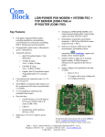
COM-5404SOFT
IP ROUTER / GATEWAY & DHCP SERVER
for GbE
VHDL SOURCE CODE OVERVIEW
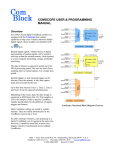
Overview
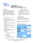
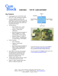
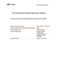
This IP router gateway connects a local IP network
(LAN) with a remote network (WAN) over a
continuous link.
The routing is based on the destination IP address.
FPGA
from WAN
via demod.
COM-5404SOFT
IP ROUTER
GATEWAY
to WAN
via modulator
Service management, ARP, PING, co-located
DHCP server, HDLC frame encapsulation, V.35
scrambling. These components are easily selected 'a
la carte' for custom applications.
Ancillary components are also included for TCP or
UDP remote monitoring and control, test signal
generation and bit error rate measurement.
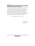
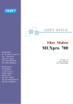
Typical application is to bridge islands of IP-based
networks through satellite / wireless / cable
modems:
o UDP video streaming
o
o
Video
streaming
source
10/100/1000
Ethernet MAC
e.g. COM-5401SOFT
RGMII/GMII
10/100/1000
Ethernet PHY IC
LAN
IP datacasting
Two-way IP communications
Video
streaming
client
LAN
UDP
LAN
UDP
IP Router
Gateway
IP Router
Gateway
130021
The COM-5404SOFT source code is designed to
support 1Gbps throughputs when instantiated in
low-cost FPGAs.
Complies with IPv4 routers specifications RFC1812
The following protocols are implemented in
modular VHDL components: IP forwarding, IP
routing, differentiated services for Quality Of
Modulator
cable/
wireless/
satellite
link
Demodulator
130020
One-way video streaming over UDP
Support for both 8-bit parallel and 1-bit serial
modem interfaces.
MSS • 845 Quince Orchard Boulevard Ste N • Gaithersburg, Maryland 20878-1676 • U.S.A.
Telephone: (240) 631-1111 Facsimile: (240) 631-1676
www.ComBlock.com
© MSS 2016
Issued 7/23/2016
The code is written specifically for IEEE 802.3
Ethernet packet encapsulation (RFC 894), IPv4
protocols.
The code interfaces seamlessly with the
COM-5401SOFT Tri-mode 10/100/1000 Mbps
Ethernet MAC for the MAC / PHY layers
implementation. However, the MAC interface is
generic and simple enough to interface with any
Ethernet MAC component with minimum glue
logic.
The component’s very efficient implementation
makes it suitable for instantiations within a small
FPGA. The baseline IP router uses 28% of a Xilinx
Spartan-6 LX45.
Principle of operation
Concept
The IP frame maximum size (maximum
transmission unit (MTU)) is 1500 bytes. No
datagram fragmentation is necessary nor used.
The IP frames are then encapsulated within a bitserial or byte-wise HDLC frame, one packet per
frame. A 16-bit CRC is inserted at the end of each
frame to detect errors upon reception. HDLC
encoding transmits empty frames when no payload
data is available.
Bit-serial HDLC frames can be subsequently
scrambled with a V.35 scrambler to ensure balance
between 0's and 1's and guarantee bit transitions (for
a well behaved modulated spectrum and to assist
demodulator acquisition when applicable).
The resulting stream is then sent to the WAN over a
continuous link, typically using a modem.
The COM-5404 forwards IP frames from a RJ-45
10/100/1000 Mbps LAN interface to a clocksynchronous modem interface and vice versa. The
interface can be 1-bit serial or 8-bit parallel.
The reverse process is performed at the receiving
end. Erroneous packets which do not pass the CRC
test are rejected.
The IP frames received over the LAN are stripped
of their link layer information: Ethernet source
address, destination address and type are removed,
keeping only the IP fields.
IP forwarding
TCP, UDP, ICMP and IGMP packets are processed
since they are transmitted as IP datagrams.
Non IP frames are rejected.
IP frames whose Time-To-Live field has reached
zero are discarded. For the other packets, the TTL is
decremented.
Limited broadcasts (those with destination IP
address 255.255.255.255) are not forwarded.
The COM-5404 implements Differentiated Services
(DiffServ) whereby IP forwarding from LAN to
WAN is prioritized on the basis of the IP frame
DSCP field. Five queues handle different traffic
classes, including Expedited Forwarding (EF) for
low-loss, low-latency, low-jitter frames and four
Assured Forwarding (AF1-AF4) classes. Frames are
discarded without notification if the associated
queue is full.
The forwarding rules are specified in the RFC1812
document “Requirements for IP Version 4 Routers”.
The decision to forward a LAN IP frame to the
remote WAN is based solely on the destination IP
address. To determine whether a frame is destined
to a local (LAN) or remote (WAN) IP address, the
router compares the masked destination address
(Destination IP address & subnet mask) with the
masked router address
(IP router own IP address & subnet mask). When
this comparison is false, the IP frame is forwarded
to the WAN.
Example:
(a) Router IP address: 192.68.0.2
(b) Router subnet mask: 255.255.255.0
(c) Frame destination IP address is 74.54.97.66
Masked frame destination: 74.54.97.0
Masked router address: 192.68.0.0
Since the masked destination does not match the
masked router address, the frame is not for a local
destination. Consequently the router will forward
the frame to the WAN.
2
Differentiated services
The router also prioritizes IP forwarding based on
the IP header differentiated services code point
(DSCP).
A forwarded IP frame is sent to one of five queues
depending on its DSCP:
Queue 4 is for low-loss, low-latency, low-jitter, and
assured bandwidth service. It is associated with
“Expedited Forwarding” per-hop behavior.
The recommended DSCP value for EF is `101110'
(see RFC-2474)
Queues 0-3 are associated with “Assured
Forwarding” per-hop behavior (see RFC-2597)
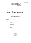
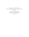
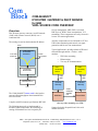
In addition to assigning IP addresses, the DHCP
server informs clients about important network
management parameters such as gateway and DNS.
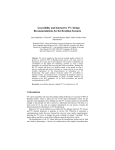
MAC
INTERFACE
DHCP
SERVER
ARP
REPLY
MAC
Receive
Interface
PACKET
PARSING
REMOTE
MONITORING
& CONTROL
INTERFACE
PING
REPLY
ROUTING
TABLE
UDP_TX
ARP
REQUEST
TCP_RXBUF
UDP_RX
Users can select the link bandwidth apportionment
among the five queues.
TCP_TXBUF
TCP
SERVER
TCP_TX
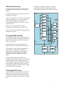
IP routing (WAN-TO-LAN)
The stream received over the link undergoes V.35
descrambling and HDLC decoding to reconstruct IP
frames. Erroneous frames which do not pass the
CRC test are rejected.
Valid IP frames are re-encapsulated inside an
Ethernet packet, one IP frame per Ethernet packet.
The IP address – MAC address relationships are
stored within a routing table to expedite the
Ethernet packet construction. The routing table
includes up to 512 local IP addresses, with
associated 48-bit MAC address and 'freshness'
stamp.
IP
FORWARDING
DIFFSERV
QUEUING
IP
ROUTING
MAC
Transmit
Interface
Arbitration
HDLC
ENCODING
HDLC
DECODING
V.35
SCRAMBLING
V.35
SCRAMBLING
WAN / MODEM
INTERFACE
140005
When the routing table has no information
regarding the destination IP address, it will attempt
to find out by means of an Address Resolution
Protocol (ARP) query-reply transaction. The router
will broadcast an ARP request asking “whois the
destination IP address?” and will wait for the ARP
reply with the MAC information.
Co-located DHCP server
A built-in DHCP server automatically assigns IP
addresses to local IP clients, for ease of network
management. The addresses are taken from a pool
of contiguous IP addresses and leased for a limited
time.
3
Target Hardware
The code is written in generic VHDL so that it can
be ported to a variety of FPGAs. The code was
developed and tested on a Xilinx Spartan-6 FPGA.
It can be easily ported to any Xilinx series 7,
Virtex-6, Spartan-6, Virtex-5 FPGAs and other
FPGAs capable of running at 125 MHz or above.
Device Utilization Summary
Device: Xilinx Spartan-6
8-bit modem interface
No DHCP server
HDLC disabled
No remote monitoring & control
Flip Flops (registers)
LUTs
Block RAM/FIFO
DSP48A1s
GCLKs
DCMs/PLLs
2033
3443
33
0
2
0
8-bit modem interface
DHCP server instantiated
HDLC disabled
No remote monitoring & control
Flip Flops (registers)
LUTs
Block RAM/FIFO
DSP48A1s
GCLKs
DCMs/PLLs
3496
5327
35
0
2
0
8-bit modem interface
DHCP server instantiated
HDLC enabled
No remote monitoring & control
Flip Flops (registers)
LUTs
Block RAM/FIFO
DSP48A1s
GCLKs
DCMs/PLLs
3963
6306
39
0
2
0
8-bit modem interface
DHCP server instantiated
HDLC enabled
1 TCP server for remote
monitoring & control
Flip Flops (registers)
LUTs
Block RAM/FIFO
DSP48A1s
GCLKs
DCMs/PLLs
5254
8155
47
0
2
0
1-bit serial modem interface
DHCP server instantiated
HDLC enabled
V.35 scrambling enabled
1 TCP server for remote
monitoring & control
Flip Flops (registers)
LUTs
Block RAM/FIFO
DSP48A1s
GCLKs
DCMs/PLLs
4073
5948
39
1
2
0
Smaller footprints can be achieved by reducing the
number of block RAMs used for implementing the
differentiated services within the
IP_FORWARDING.vhd component (currently set
at 32 block RAMs).
4
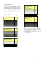
Interfaces
CLK
SYNC_RESET
LAN / MAC
MAC_TX_DATA[7:0]
MAC_TX_DATA_VALID
MAC_TX_SOF
MAC_TX_EOF
MAC_TX_CTS
MAC_RX_DATA[7:0]
MAC_RX_DATA_VALID
MAC_RX_SOF
MAC_RX_EOF
CONFIGURATION
MAC_ADDR[47:0]
IPv4_ADDR[31:0]
SUBNET_MASK[31:0]
GATEWAY[31:0]
ROUTER config.
DHCP_SERVER config.
DIFFSERV config.
Configuration
The key configuration parameters are brought to the
interface so that the user can change them
dynamically at run-time. Other, more arcane,
parameters are fixed at the time of VHDL synthesis.
WAN / MODEM
WAN_TX_DATA[7:0]
WAN_TX_DATA_VALID
WAN_TX_SOF
WAN_TX_EOF
WAN_TX_CTS
Pre-synthesis configuration parameters
WAN_RX_DATA[7:0]
WAN_RX_DATA_VALID
WAN_RX_SOF
WAN_RX_EOF
WAN_RX_CTS
The following configuration parameters are set
prior to synthesis in the com5404.vhd top level
component generic section.
Configuration
Description
parameters in
com5404.vhd generic
section
REMOTE M&C
TCP_RX_DATA[7:0]
TCP_RX_DATA_VALID
TCP_RX_RTS
TCP_RX_CTS
DHCP server
HDLC codec
TCP_TX_DATA[7:0]
TCP_TX_DATA_VALID
TCP_TX_CTS
140006
Interface groups
WAN data width
This interface comprises four primary I/O groups:
LAN/MAC interface (direct connection to COM5401SOFT MAC core or equivalent), remote
Monitoring & Control interface, WAN/modem
interface and controls.
All signals are clock synchronous with a userselected clock CLK (it does not have to be the same
as the PHY clock). To guarantee a 1 Gbps
throughput, a minimum 125 MHz clock speed is
required.
All interfaces are buffered by internal elastic buffers
in both transmit and receive directions.
Flow control signals Clear-To-Send (CTS) and
Ready-To-Send (RTS) help regulate data
throughput and avoid overflow/underflow
conditions.
Monitoring & Control
TCP server
Monitoring & Control
UDP server
DHCP_SERVER_EN
‘1’ to instantiate a DHCP
server
HDLC_EN
Instantiate ('1') the HDLC
encoder and decoder within.
Also applies to the V.35
scrambler/descrambler
WAN_NBITS
configures for either 1-bit
serial or 8-bit parallel WAN
interface
-MUST be set to 8-bit parallel
when HDLC is not
instantiated (HDLC_EN = '0')
REMOTE_MC_TCP.
‘1’ to instantiate a TCP server
at port 1028 for conveying
monitoring and control
messages from a remote
user/client.
‘0’ otherwise
REMOTE_MC_UDP.
‘1’ to instantiate a UDP
server at port 1029 for
receiving control messages
from a remote user/client.
‘0’ otherwise
5
Run-time configuration parameters
The user can set and modify the following controls
at run-time. All controls are
synchronous with the user-supplied
global CLK.
IP router run-time
Description
configuration
MAC address
MAC_ADDR(47:0)
This network node 48-bit MAC
address. The user is responsible
for selecting a unique ‘hardware’
address for each instantiation.
Natural bit order: enter
x0123456789ab for the MAC
address 01:23:45:67:89:ab
It is essential that this input
matches the MAC address used
by the MAC/PHY.
IPv4 address
Local IP address. 4 bytes for
IPv4_ADDR(31:0)
IPv4.
Byte order:
(MSB)192.68.1.30(LSB)
Subnet Mask
Subnet mask to assess whether
SUBNET_MASK(31:0) an IP address is local (LAN) or
remote (WAN)
Byte order:
(MSB)255.255.255.0(LSB)
Gateway IP address
The router will forward IP
GATEWAY_IP(31:0)
frames from the WAN to this
gateway when the destination IP
is not local
Byte order:
(MSB)192.68.1.1(LSB)
Controls
bit 0: enable(1)/disable(0) HDLC
CONTROL(15:0)
encoding [1 or 8-bit format]
bit 1: enable(1)/disable(0) V.35 bit
serial scrambling [applies to 1bit serial format only]
bit 8: enable(1)/disable(0)
HDLC decoding [1 or 8-bit
format]
bit 9: enable(1)/disable(0) V.35
bit serial descrambling [applies
to 1-bit serial format only]
DHCP server runtime configuration
Description
DHCP server enable
enable(1)/disable(0) DHCP
server at run-time. Requires
DHCP_SERVER to be
instantiated through
DHCP_SERVER_EN
The DHCP server IP pool starts
at this address. The 3 upper
address bytes are
DHCP_SERVER_EN2
DHCP server IP pool
start address
DHCP_SERVER_IP_
MIN_LSB
DHCP server IP pool
size
DHCP_SERVER_NIPs
Lease time
DHCP_SERVER_
LEASE_TIME
Gateway address
DHCP_ROUTER
IPv4_ADDR(31:8)
In order to avoid conflicts, it is
best to select a start address
above this router own Ipv4
address.
Number of IP addresses in the
DHCP server IP pool.
Maximum: 253-IPv4_ADDR(7:0)
Lease time, in seconds, of IP
addresses assigned to DHCP
clients.
The DHCP server informs its
clients of a gateway to the
WAN. In most cases, this is the
co-located router IP address
IPv4_ADDR
DNS address
DHCP_SERVER_DNS
The DHCP server informs its
clients of a domain name server
DNS address.
Limitations
This software does not support the following:
- IEEE 802.3/802.2 encapsulation, RFC
1042, only the most common Ethernet
encapsulation.
Only one gateway is supported at any given time.
Software Licensing
The COM-5404SOFT is supplied under the
following key licensing terms:
1. A nonexclusive, nontransferable license to
use the VHDL source code internally, and
2. An unlimited, royalty-free, nonexclusive
transferable license to make and use products
incorporating the licensed materials, solely in
bitstream format, on a worldwide basis.
The complete VHDL/IP Software License
Agreement can be downloaded from
http://www.comblock.com/download/softwarelicense.pdf
6
Configuration Management
The current software revision is 1c.
Directory
Contents
/
Project files for various Xilinx ISE
versions.
/doc
Specifications, user manual,
implementation documents
/src
.vhd source code, .ucf constraint files,
.pkg packages.
One component per file.
Testbenches
/sim
/bin
/use_example
Xilinx-specific code
The VHDL source code is written in generic VHDL
with one Xilinx primitive (dual-port block RAM).
No Xilinx CORE is used.
Top-Level VHDL hierarchy
.ngc, .bit, .mcs configuration files
use example, .ngc for Spartan-6 and
instantiation template
Test components (pseudo random binary
sequence generator, bit error rate
measurement, stream to packets
segmentation, etc) are in directory
\use_example\src
Key file:
Xilinx ISE project file: com-5404_ISE144.xise
VHDL development environment
The VHDL software was developed using the
following development environment:
(a) Xilinx ISE 14.4 with XST as synthesis tool
(b) Xilinx ISE Isim as VHDL simulation tool
Ready-to-use Hardware
The project in the use_example folder is ready-touse with the following off-the-shelf hardware :
COM-1500 FPGA + ARM + DDR2
SODIMM + NAND + USB2 development
platform
COM-5102 1-Port 10/100/1000 Mbps
Ethernet Transceiver
The code is stored with one, and only one,
component per file.
The root entity (highlighted above) is
COM5404.vhd. It contains instantiations of the IP
router, DHCP server, TCP server and ancillary
components.
The root also includes the following components:
-
The PACKET_PARSING.vhd component
parses the received packets from the MAC
and efficiently extracts key information
relevant for multiple protocols. Parsing is
done on the fly without storing data.
Instantiated once.
-
The ARP.vhd component detects ARP
requests and assembles an ARP response
Ethernet packet for transmission to the
MAC. Instantiated once.
-
The PING.vhd component detects ICMP
echo (ping) requests and assembles a ping
echo Ethernet packet for transmission to the
MAC. Instantiated once.
7
-
The WHOIS2.vhd component generates an
ARP request (broadcast) packet requesting
that the target identified by its IP address
responds with its MAC address.
-
The ARP_CACHE3.vhd component is a
shared database storing up to 512 IP
addresses with their associated 48-bit MAC
addresses and a ‘freshness’ timestamp. An
arbitration circuit is used to arbitrate the
routing request from multiple transmit
instances. Instantiated once.
-
The IP_FORWARDING.vhd component
filters those LAN IP frames with remote
destination and queues them in five priority
queues awaiting transmission to the WAN.
-
The HDLC_SERIAL_2TX.vhd component
encapsulates IP frames for transmission
over a bit-serial continuous link. It also
inserts empty frames when no payload data
is waiting for transmission. A 16-bit CRC
field is appended to each frame for error
detection at the receiving end.
-
-
-
The HDLC_SERIAL_2RX.vhd component
processes the received bit-serial continuous
stream. It restores the IP frames by
removing the HDLC frame encapsulation
after verifying the frame integrity (valid
CRC, etc).
The HDLC_BYTE_TX.vhd component
encapsulates IP frames for transmission
over a byte-wide continuous data link. It
also inserts empty frames when no payload
data is waiting for transmission. A 16-bit
CRC field is appended to each frame for
error detection at the receiving end.
The HDLC_BYTE_RX.vhd component
processes the received byte-wide
continuous stream. It restores the IP frames
by removing the HDLC frame
encapsulation after verifying the frame
integrity (valid CRC, etc).
-
The V35SCRAMBLER.vhd component can
be configured as scrambler or descrambler.
It complies with the V.35 and Intelsat
IESS-308 standards.
-
The IP_ROUTING.vhd component converts
8-bit parallel stream from WAN to LAN IP
packets. Each incoming IP frame received
from the WAN is stored temporarily in one
of the NBUFS buffers until routing
information (namely the destination MAC
address) is received from the
ARP_CACHE3.vhd routing table. When
this happens, the IP frame is encapsulated
into an Ethernet frame and sent to the LAN.
-
The TCP_SERVER.vhd component is one
of four components implementing a TCP
server for remote monitoring and control.
It awaits one TCP connection at port 1028
from a remote client. It essentially handles
the TCP state machine of a TCP server:
initially listening for connection requests
from remote TCP clients, establishing and
tearing down the connections and managing
flow control while the connections are
established.
-
The TCP_TX.vhd component formats TCP
tx frames, including all layers: TCP, IP,
MAC/Ethernet.
-
The TCP_TXBUF.vhd component stores
TCP tx payload data in individual elastic
buffers, one for each transmit stream. The
buffer size is configurable prior to synthesis
as NBUFS*16Kbits RAM blocks.
-
The TCP_RXBUFNDEMUX2.vhd
component demultiplexes several TCP rx
streams and stores data in elastic buffers.
Data bytes are received in sequence without
gaps or backtracking.
Additional components are also provided for use
during system integration or tests.
-
LFSR11P.vhd generates a pseudo-random
binary stream PRBS11 for use during
throughput and bit error rate tests. It is
capable of generating 1 Gbps (8 bit per
clock @ 125 MHz).
-
BER2.vhd synchronizes with a received
data stream and counts bit errors. It is also
capable of working at 1 Gbps.
8
VHDL simulation
Several complex testbenches (tb*.vhd) are located
in the /sim directory. However, these testbenches
simulate complex environments (end-to-end TCP
client/server connections) and require additional
components such as TCP server, TCP client and
DHCP client. There is no simple standalone
testbench.
Clock / Timing
The software uses one synchronous clock CLK. The
clock should be at least 125 MHz in order to take
full advantage of the Gbit Ethernet speed. The code
can operate properly at less than 125 MHz, albeit at
reduced throughput.
The code is written to run at 125 MHz on a Xilinx
Spartan-6 –2 speed grade.
9
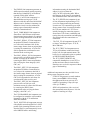
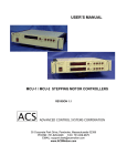
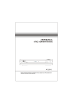
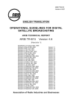
Network Administration
GbE LAN
Simple network administration
DHCP server
assigned
dynamic IP
addresses
GbE LAN
synchronous
serial link
(cable,
satellite, etc)
172.16.1.10
static IP
172.16.1.1
172.16.1.11
172.16.1.12
COM-5404
Gateway1
DHCP server enabled
Base IP address:
172.16.1.10
COM-5404
Gateway2
192.68.0.20
192.68.0.21
DHCP server enabled
Base IP address:
192.68.0.20
172.16.1.13
Network devices
configured as
"DHCP enabled"
(dynamic IP addresses
are assigned automatically
by a DHCP server)
static IP
192.68.0.2
192.68.0.22
192.68.0.23
Gateway3
static IP
192.68.0.1 192.68.0.24
GbE LAN
Network devices
configured as
"DHCP enabled"
(dynamic IP addresses
are assigned automatically
by a DHCP server)
Internet
The diagram above illustrates a simple network administration scheme, whereby only gateways are administered
with fixed (static) IP addresses. The other network devices automatically fetch their network configuration (IP
address, subnet mask, DNS) from a DHCP server, like the one in the COM-5404.
For example, a PC running Microsoft’s Windows
operating system would be configured as per the right
panel:
10
ComBlock Compatibility List
FPGA development platform
COM-1500 FPGA + DDR2 SODIMM socket + ARM development platform
COM-1700 Low-power compact development Platform FPGA + ARM + DACs + ADCs + VGA +
GbE LAN + USB2+ NAND + TCXO + RS422
Network adapter
COM-5401 4-port 10/100/1000 Mbps Ethernet Transceivers
COM-5102 Gigabit Ethernet + HDMI interface
Software
COM-5401SOFT Tri-mode 10/100/1000 Mbps Ethernet MAC. VHDL source code.
ComBlock Ordering Information
COM-5404SOFT IP ROUTER GATEWAY & DHCP SERVER for GbE, VHDL SOURCE CODE
ECCN: 5E001.b.4
MSS • 845 Quince Orchard Boulevard Ste N •
Gaithersburg, Maryland 20878-1676 • U.S.A.
Telephone: (240) 631-1111
Facsimile: (240) 631-1676
E-mail: [email protected]
LAN = Local Area Network
WAN = Wide Area Network
M&C = Monitoring & Control
11