1
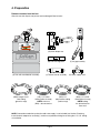
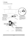
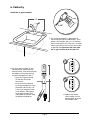
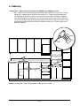
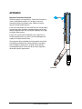
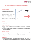
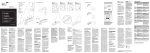
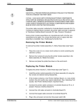
STATFlow Direct-to-Drain System
™
For use with STATIM® 2000 and STATIM 5000 Autoclaves
STATFlow Installation Guide and Operator’s Manual 95-113193 Rev 2.0. Copyright 2012 SciCan Ltd. All rights reserved.
• Installation Guide and
Operator’s Manual
Table of Contents
1. Introduction ................................................................................................................. 1
2. Important Information ................................................................................................. 1
3. Installation Overview ................................................................................................... 2
4. Preparation .................................................................................................................. 4
5. Plumbing Modifications .............................................................................................. 5
6. Cabinetry Modifications .............................................................................................. 6
7. Connecting Tubing ...................................................................................................... 8
8. Getting Started .......................................................................................................... 10
9. Maintenance .............................................................................................................. 11
10. Troubleshooting ....................................................................................................... 11
Specifications
STATFlow Direct-to Drain System
Tank material
Polyethylene regrind
Tank dimensions
19.3 cm x 19.3 cm x 27.3 cm (7.6 in x 7.6 in x 10.75 in)
Tank volume
5.7 L (1.5 gallon)
Tank weight with water
6.8 kg (15 lbs)
Cold water connectionConnection for 1/4” OD tubing required
(not supplied, to be done by plumber)
Inlet water pressure
1 - 7 bar (14.5-101.5 psi)
Ambient operating temperature and humidity 5°C - 40°C (41°F - 104°F);
80% max. humidity
Max. altitude
2000 m
For additional information:
Manufactured by:
SciCan Ltd.
1440 Don Mills Road,
Toronto, ON M3B 3P9
CANADA
Phone: (416) 445-1600
Fax: (416) 445-2727
Toll free: 1-800-870-7777
SciCan, Inc.
701 Technology Drive
Canonsburg, PA15317
USA
Phone: (724) 820-1600
Fax: (724) 820-1479
Toll Free: (800) 572-121
U.S. service information
United States: 1-800-572-1211
Email: [email protected]
Canada: [email protected]
USA: [email protected]
STATIM is a registered trademark and STATFlow and “Your Infection Control Specialist” are trademarks of SciCan Ltd.
STATFlow is manufactured by SciCan Ltd. under license from Vista Research Group, LLC. Patent pending.
SciCan STATFlow
1. Introduction
About the STATFlow Direct-to-Drain System
The STATFlow Direct-to-Drain system replaces the need for a STATIM condenser/waste bottle by cooling
the exhaust water from STATIM 2000 and STATIM 5000 autoclaves and automatically sending it directly
down the drain.
About this Installation Guide and User Manual
This manual was created as a reference for the installation of the STATFlow Direct-to-Drain System and
to provide information to users concerning the care and operation of the system.
If you have a question about the unit you are installing, please contact your local SciCan representative.
Any installation of the STATFlow must observe the plumbing code criteria as specified by the
municipality or region governing the installation site.
Recommendation: kit to be installed by a service professional.
2. Important information
Warnings and Precautions
The details of installing and operating your STATFlow system are all contained within this manual.
Installation and maintenance instructions should be followed for the system to perform as designed.
The STATFlow system is designed specifically to function with STATIM 2000/5000 and
STATIM G4 2000/5000 (available in Canada only). It is not designed for use with other models
or products. Using it with other models or products may result in damage to equipment or
plumbing infrastructure.
Do not permit any person other than certified personnel to supply parts for, service, install or
maintain your STATFlow system. SciCan will not be liable for incidental, special or consequential
damages caused by any maintenance or services performed on the STATFlow system by a third
party, or for the use of equipment or parts manufactured by a third party, including lost profits,
any commercial loss, economic loss, or loss arising from personal injury.
Ensure correct water tank height
As a non-pressurized system, the STATFlow must be installed so that the top of water tank is below
the lowest point on the air gap assembly and above the connection to drain. Typically this will
require elevating the water tank. If a STATFlow system is installed without respecting these relative
heights, it may not function properly.
Perform tests
When the installation is complete, turn on the water supply and check for leaks. If there are no
leaks, run three consecutive cycles with the STATIM. Check for leaks and watch the tubing to
ensure water is draining correctly.
Page 1
3. Installation overview
Side view
STATIM
F
YEL
O
RED
N
M
FLOW
200
RED
H
RED
BLU
J
Q
P
C
BLU
B
D
L
BLU
G
K
A
Hot
Cold
Page 2
GRN
E
3. Installation overview
F
Top view
STATIM
O
N
YEL
GRN
J
BLU
BLU
G
K
M
P
Q
C
D
BLU
W
FLO
200
L
RED
B
E
A
RED
COLD WATER
H
RED
Page 3
4. Preparation
Remove contents from the box.
Check to see that all parts are present and undamaged. Box includes:
(G) Drain adapter tee
FLOW
200
(A) Tank with manifold/coil assembly
(GRN) Length of 3/8”
clear tubing
(green tie wrap)
(M) Flow rate regulator
(F) Air gap assembly
(J) Thermal sensor assembly
(H) Water supply valve
(YEL) 1/4” Teflon
tubing (yellow tie wrap)
NOTE: similar to
(BLU) – do not confuse
(RED) 1/4”
polyurethane tubing
(red tie wrap)
(BLU) 1/4” LLDPE
tubing (blue tie wrap)
NOTE: tubing
has printed text on
outer wall
NOTE: Connection needed to tap into the cold water supply is not included (see Section ‘Plumbing.
Install the drain adapter tee assembly’), installer must provide a fitting for receiving the 1/4” O.D. tubing
at installation.
Page 4
RED
5. Plumbing
Install the drain adapter tee assembly.
RED
RED
1. Tap the cold water
supply line and connect
a 3” to 4” section of ¼”
clear tubing (RED) to the
water supply valve (H).
2. Attach water supply valve
(H) by pushing the clear ¼”
tubing (RED) into the pressure
fitting. Be certain the valve is
in the closed position with the
blue lever at 90-degrees to
the valve.
RED
NOTE: Connection needed
to tap into cold water
supply is not included.
Installer must provide a
fitting for receiving the ¼”
OD tubing at installation.
G
1” minimum
Hot
H
Cold
Page 5
3. Measure the drain adapter tee
assembly for placement on the
drain assembly. Cut and remove
a section of the drain assembly
above the P-trap. Install the
drain adapter tee (G) as low as
possible, while maintaining a
minimum 1” offset from the drain.
6. Cabinetry
Install the air gap assembly.
OR
1-1/4”
1. The air gap assembly (F) is designed to fit
into the sprayer hole of standard sinks. If this
option is not available, drill a 1-1/4” diameter
hole in the lip of the sink. If the sink is an under
mount style, drill the hole as close to the edge
as possible. It is important that water from
the air gap assembly drain into the sink.
8
2. On the air gap assembly (F), pull
upwards on the chrome cover to
remove the top. Then remove the top
threaded nut and washer, leaving
the lower threaded nut in place.
• Insert the air gap assembly
(F) into hole from under
the counter.
• Place the washer followed
by the top threaded nut at top
of threads and turn only 2 to
3 times (just enough to catch
a few threads). Then tighten
the air gap assembly from
OR
underneath the counter using
the bottom threaded nut.
F
4
3. Replace the chrome
cover making sure the
opening does not reveal
the overflow outlet.
OR
Page 6
F
6. Cabinetry
4. Route the ¼” Teflon exhaust tubing from the STATIM to the STATFlow system.
• Drill ½” holes in the cabinetry between the STATIM and the STATFlow system. Use ¼” Teflon
tubing (YEL) supplied with the STATFlow. Be certain the ¼” Teflon tubing runs down from
the STATIM to the STATFlow system. The entry hole into the cabinet housing the STATFlow
tank should be higher than the top of the tank (see section ‘Starting and using the STATFlow
system’ for tank placement). When possible, tubing should not have any level sections where
water draining from the STATIM can collect. Avoid areas where the ¼” Teflon tubing can be
pinched by drawers.
1/2”
STAT IM
STATFlow
YEL
NOTE: extra long (16ft / 4.9m) tubing available as spare part (ol-1134685)
Page 7
7. Connecting tubing
IMPORTANT INFORMATION
• All tubing cuts must be even and clean.
• All fittings are a push-to-connect design, except the barbs on the brass water valve.
• Use a twisting motion when pushing tubing into fitting to ensure ends are fully inserted.
• Do NOT use any lubricants other than clean water. Moisten the tubing ends with water
before inserting into fittings if lubrication is needed.
• Cut tubing to allow sufficient length so that no tubing line is tight or stressed and so that
tank assembly can be moved within the cabinet.
• Tubing connecting to drain should be as short as possible and must not droop, loop or
sag in a way that would form a trap that can cause flow resistance.
• Ensure that flow is not impeded by kinked or bent tubes.
1. Fill the water tank.
C
• Remove the manifold and coil assembly
(C) from the water tank (A).
• Fill tank completely. Place the
full water tank under the sink.
A
Page 8
7. Connecting tubing
F
STATIM
O
N
YEL
GRN
J
BLU
BLU
G
K
M
P
BLU
Q
C
D
W
FLO
200
L
RED
B
E
A
RED
COLD WATER
H
RED
2. Connect the water supply to the water tank. Using ¼” clear tubing (RED), connect one end to the
water coolant valve (H) by pushing tubing into the push-to-connect fitting and the other end to the top
of the fitting on the brass valve (B) of the water tank (warm the tubing with hot water and make sure
the tubing is pushed down so that it is flush with the top of the steel hex nut).
3. Connect the air gap to the water tank.
• Using a section of ¼” clear tubing (RED), push one end into the smaller ¼” leg (N) of air gap
assembly (F) and the other end into the flow rate regulator (M). The arrow on the flow rate
regulator should be pointing towards the air gap assembly.
• Cut another section of ¼” clear tubing (RED). Push one end into the flow rate regulator and the
other end onto the side fitting on the brass valve (B) of the water tank (warm the tubing with hot
water and make sure the tubing is pushed all the way onto the fitting).
• Using the larger diameter 3/8” clear tubing (GRN), connect the 3/8” inlet fitting on the large leg
(O) of the air gap assembly (F) to the coolant inlet fitting (E) on the water tank.
4. Connect the STATIM exhaust to the manifold. Connect the ¼” Teflon tubing (YEL) from the STATIM
exhaust to the white Kynar inlet fitting (P) on the top of the manifold. Be sure that this tube does not
kink when installed or when moving the STATIM.
5. Connect the manifold to the drain. Remove the tubing loop on the drain adapter tee (G) and connect
a section of ¼” LLDPE tubing (BLU) from the outlet fitting (Q) on the manifold to the upper input (L) on
the drain adapter tee. Cut this ¼” LLDPE tubing (BLU) and insert the in-line thermal sensor (J) oriented
with the arrow pointing towards the drain and the black gasket closest to the drain.
6. Connect the water tank overflow port to the drain. Use ¼” LLDPE tubing (BLU) and connect the
overflow port (D) on the water tank (A) to the lower input (K) on the drain adapter tee.
Page 9
8. Getting started
IMPORTANT INFORMATION
Ensure correct water tank height
As a non-pressurized system, the STATFlow must be installed so that the top of water tank
is below the lowest point on the air gap assembly and above the connection to the drain.
Typically this will require elevating the water tank. A STATFlow system installed without
respecting these relative heights may not function properly.
Starting and using the STATFlow system
1. Turn on the water supply and check for leaks.
2. Slowly open the water supply valve (H) to the STATFlow system and check for leaks.
3. Prime the system by inserting a small screwdriver in the hole at the base
of the water tank’s brass valve (B) and pushing up on the poppet valve.
The system is primed when water can be seen leaving the overflow valve
through the tubing to the drain adapter tee.
4. Set the water tank in an elevated position above the drain connections
on the P-trap to ensure proper drainage. The correct height will vary
with each installation. What is most important is to ensure the top of the
water tank is LOWER than the air gap assembly legs and ABOVE the drain
points in the drain adapter tee.
B
5. When the installation is complete, turn on the water supply and check
for leaks. If there are no leaks, run 3 consecutive cycles with the STATIM.
Check for leaks and watch tubing to ensure that the water is draining correctly.
6. Use the STATFlow system. Since the STATFlow system is designed as a low-maintenance,
automatic alternative to using condenser/waste bottles, once it is properly primed it will function
without operator input. Beyond periodic visual inspections of the tubing, there is nothing an
operator must do to ensure continued and safe operation.
Page 10
9. Maintenance
The STATFlow Direct-to-Drain system is designed to require minimum maintenance. However, it is
recommended that operators periodically verify that the tubing and connections are free of mineral
deposits and not compromised in any way. The system includes several failsafe devices designed to
stop the flow of exhaust water from the STATIM in the event of a problem.
Operator
Every 6 monthsCheck clear tubing for mineral deposits. Visually inspect all connections
to ensure there are no leaks.
Technician
Once a year
Visually inspect system checking for leaks.
10. Troubleshooting
ProblemCause/solution
System is not draining
• Ensure water supply valve is in ON position.
• Check for blockages in tubing.
• Check water level in tank.
STATIM is displaying cycle fault 10 or 11
• Exhaust port is blocked. Check for kinks in tubing from
Statim to STATFlow system (drawers pinching line, etc…)
• Check that water is draining.
Water is coming out of air gap assembly / there is water on the counter • Ensure sink is not plugged.
• Raise water tank so that top of tank is above the drain point
and below the air gap as described in Chapter 8: Getting Started.
Water tank is bloated
• Raise water tank so that top of tank is above the drain point
and below the air gap as described in Chapter 8: Getting Started.
Check the connections on the barb – ensure that water supply
is attached to the top barb and the flowrate regulator/air gap is
attached to the side barb.
Water leaking under counter
• Check all tubing connections.
• Push in all connections to ensure tubing is solidly engaged.
Page 11
APPENDIX
Backflow Prevention Overview
Airflow
STATFlow employs an air gap that is a totally non-mechanical
means of backflow prevention. The air gap is a physical
separation between the potable water supply line and the
non-pressurized condensing tank.
In the event of backflow from the STATFlow tank, the potentially
contaminated water would be expelled through the drain hole
and discharged into the sink (see Section Cabinetry for air gap
installation requirements).
If there were suction from the potable water supply line, air
would be pulled into the city source since the opening of the
supply line is above the drain hole.
The air gap has been certified by the International Association
of Plumbing and Mechanical Officials (IAPMO) as compliant
with the product’s performance standard and the Uniform
Plumbing Code (UPC). Please refer to your local regulations
for location specific requirements.
Backflow
SciCan STATFlow Appendix