1
SifoWorks D-Series 3.04 Firewall
User Manual
OD1300UME01-1.3
NOTICE
No part of this document may be reproduced or transmitted in any form or by any means, electronic or mechanical, for any purpose,
without receiving written permission from O2Security.
O2Security and its subsidiaries reserve the right to make changes to their documents and/or products or to discontinue any product
or service without notice, and advise customers to obtain the latest version of relevant information to verify, before placing orders,
that information being relied on is current and complete. All products are sold subject to the terms and conditions of sale supplied at
the time of order acknowledgement, including those pertaining to warranty, patent infringement, and limitation of liability.
O2Security warrants performance of its products to the specifications applicable at the time of sale in accordance with O2Security’s
standard warranty. Testing and other quality control techniques are utilized to the extent O2Security deems necessary to support this
warranty. Specific testing of all parameters of each device is not necessarily performed, except those mandated by government
requirements.
Customer acknowledges that O2Security products are not designed, manufactured or intended for incorporation into any systems or
products intended for use in connection with life support or other hazardous activities or environments in which the failure of the
O2Security products could lead to death, bodily injury, or property or environmental damage ("High Risk Activities"). O2Security
hereby disclaims all warranties, and O2Security will have no liability to Customer or any third party, relating to the use of O2Security
products in connection with any High Risk Activities.
Any support, assistance, recommendation or information (collectively, "Support") that O2Security may provide to you (including,
without limitation, regarding the design, development or debugging of your circuit board or other application) is provided "AS IS."
O2Security does not make, and hereby disclaims, any warranties regarding any such Support, including, without limitation, any
warranties of merchantability or fitness for a particular purpose, and any warranty that such Support will be accurate or error free or
that your circuit board or other application will be operational or functional. O2Security will have no liability to you under any legal
theory in connection with your use of or reliance on such Support.
Information in this document is subject to change without notice.
©2008 O2Security Ltd. All rights reserved. O2Security is a subsidiary of O2Micro International Ltd. (NASDAQ:
OIIM, SEHK: 0457). O2Security is a trademark and SifoWorks is a registered trademark of O2Micro
International Ltd.
Table of Contents
1 Product Overview .........................................................................................................................1
1.1 What is SifoWorks? .........................................................................................2
1.2 SifoWorks’Hardware Specifications ....................................................................2
1.3 What can SifoWorks Do?..................................................................................5
1.4 System Specifications ................................................................................... 13
2 Getting started .............................................................................................................................15
2.1 SifoWorks Deployment Topology ..................................................................... 16
2.2 Basic System Operations ............................................................................... 19
2.3 SifoWorks User Interface ............................................................................... 23
2.4 Task List...................................................................................................... 33
2.5 Device Quick Configuration Guide ................................................................... 38
3 Network Configuration .............................................................................................................41
3.1 Overview..................................................................................................... 43
3.2 Setting up the Basic Network Settings ............................................................. 43
3.3 Configuring Network Address Translation ......................................................... 59
3.4 Setting up DHCP Service ............................................................................... 69
3.5 Configuring PPPoE Connections....................................................................... 73
3.6 Specifying DNS Servers ................................................................................. 76
3.7 Configuring DDNS ........................................................................................ 76
3.8 Managing IP-MAC Bindings ............................................................................ 78
3.9 Managing the ARP Tables ............................................................................... 82
4 Firewall Rule Management.......................................................................................................85
4.1 Overview..................................................................................................... 86
4.2 Managing Filter Rules .................................................................................... 87
4.3 Managing Local Rules .................................................................................... 99
4.4 Managing Content Filtering Rules .................................................................. 101
5 Intrusion Detection and Prevention......................................................................................109
5.1 Overview................................................................................................... 110
5.2 Configuring and Enabling IDP ....................................................................... 110
5.3 Upgrade IDP Rules...................................................................................... 116
6 Virtual Private Networks.........................................................................................................117
6.1 Overview................................................................................................... 118
6.2 Configuring IPsec VPN Connections ............................................................... 120
6.3 Configuring PPTP VPN Connections................................................................ 141
6.4 Configuring L2TP VPN Connections ................................................................ 144
7 Advanced Functions .................................................................................................................147
7.1 Overview................................................................................................... 148
7.2 Setting Up QoS Services.............................................................................. 148
7.3 Limiting IP Traffic ....................................................................................... 152
7.4 Activating High Availability ........................................................................... 157
7.5 Configuring IDS Services ............................................................................. 163
7.6 Upgrade Intelligent Recognized Protocols (IRP) ............................................... 174
8 Log Management.......................................................................................................................175
8.1 Overview................................................................................................... 176
8.2 Managing Log Servers ................................................................................. 178
8.3 Configuring Log Attributes ........................................................................... 179
8.4 Exporting Log ............................................................................................ 179
8.5 Customizing Log Filter Criteria and Log Format ............................................... 180
8.6 Setting up Email Alerts................................................................................ 181
8.7 Viewing Logs ............................................................................................. 182
9 System Settings .........................................................................................................................183
9.1 Overview................................................................................................... 184
9.2 Managing Administrator Accounts ................................................................. 184
9.3 Setting Up Basic System Configuration .......................................................... 189
9.4 Import/Export Configuration File................................................................... 191
9.5 Upgrade System Software ........................................................................... 192
9.6 Connect to a Network Management System.................................................... 193
9.7 Configuring Timeout Values.......................................................................... 200
10 System Maintenance ..............................................................................................................203
10.1 Overview ................................................................................................. 204
10.2 Monitoring Sessions and Online Users .......................................................... 204
10.3 Viewing Reports ....................................................................................... 206
10.4 Performing Network Diagnostics.................................................................. 212
10.5 Restoring System Settings ......................................................................... 214
11 Device Deployment Example ...............................................................................................217
11.1 Network Topology and Company Requirements ............................................. 218
11.2 Configuration Flowchart ............................................................................. 222
11.3 Phase 1 – Configuring the Basic Network Settings ......................................... 223
11.4 Phase 2 – Configuring NAT ......................................................................... 227
T
11.5 Phase 3 – Defining Filter Rules.................................................................... 229
11.6 Phase 4 – Configuring VPN ......................................................................... 243
11.7 Phase 5 – Setting up IDS ........................................................................... 249
1
Chapter
Product Overview
1
This chapter includes the following sections:
z
What is SifoWorks?
Briefly introduces the SifoWorks firewall device and lists the various
device models in the product series.
z
What does SifoWorks Look Like?
Displays the physical SifoWorks device box. This section also
introduces the various device ports and the LED indicator lights.
z
What can SifoWorks Do?
Introduces the main functions of the SifoWorks firewall.
z
System Specifications
Contains information on the various SifoWorks devices’ performance
and capacity indexes, device dimensions, power supply requirements,
operating environment and reliability factor.
For an overall understanding of the SifoWorks firewall, please refer to this
chapter.
User Manual for SifoWorks D-Series Firewall
1
OD1300UME01-1.3
Chapter 1 Product Overview
1.1 What is SifoWorks?
O2Security’s new generation firewall product, SifoWorks, is a multifunctional security gateway system equipped with the best data packet
handling capability in the industry. SifoWorks also supports various other
security mechanisms such as firewall, IPsec VPN, content filtering etc.,
providing security on higher network levels, and thus enhancing the
overall security of user’s networks.
The SifoWorks D-series family includes the following device models:
z
SifoWorks D100
z
SifoWorks D200
z
SifoWorks D300
The term “SifoWorks” is used in this document to refer to all the above
models.
1.2 SifoWorks’ Hardware Specifications
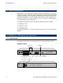
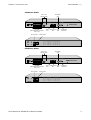
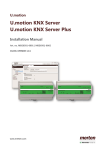
1.2.1 Device Box
The figures below show the physical device of each SifoWorks models.
SifoWorks D100
(FE0~FE7)
Network LEDs
FE0
FE1
FE2
FE3
FE4
FE5
FE6
FE7
R
2
0 1 2 3
SifoWorks D100
Breathing Life into SecurityTM
4 5 6 7
10M/100M
Self-adaptive Ethernet Ports
(FE0~FE7)
Power Socket
2
Read/Write
LED
MGT1
ADSL
Port
MGT0
Management Power
LED
Port
CONSOLE
Management
Serial Port
Power Switch
User Manual for SifoWorks D-Series Firewall
Chapter 1 Product Overview
OD1300UME01-1.3
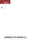
SifoWorks D200
(FE0~FE7)
Network LEDs
FE0
FE1
FE2
FE3
FE4
FE5
FE6
FE7
R
2
Read/Write
LED
0 1 2 3
SifoWorks D200
Breathing Life into SecurityTM
4 5 6 7
10M/100M
Self-adaptive Ethernet Ports
(FE0~FE7)
Power Socket
MGT1
ADSL
Port
CONSOLE
MGT0
Management Power
LED
Port
Management
Serial Port
Power Switch
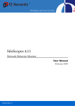
SifoWorks D300
(FE0~FE7)
Network LEDs
FE0
FE1
FE2
FE3
R
2
Read/Write
LED
0 1 2 3
SifoWorks D300
Breathing Life into SecurityTM
FE4
FE5
FE6
FE7
4 5 6 7
10M/100M
Self-adaptive Ethernet Ports
(FE0~FE7)
Power Socket
MGT1
ADSL
Port
MGT0
Management Power
LED
Port
CONSOLE
Management
Serial Port
Power Switch
User Manual for SifoWorks D-Series Firewall
3
OD1300UME01-1.3
Chapter 1 Product Overview
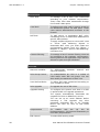
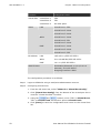
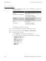
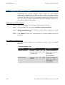
1.2.2 Device Ports
Name
Explanation
Type
FE0 – FE7
10M/100M self-adaptive Ethernet
ports
RJ-45
For connection to networks with
10M/100M speed to monitor and
filter data packets
MGT1
Used for ADSL connections. The
device can be connected to the
Internet using PPPoE via a ADSL
modem
RJ-45
MGT0
To connect to an administrative PC
via a standard network cable for
system configuration
RJ-45
Monitor ports are also used as the
heartbeat monitoring port under HA
mode
CONSOLE
RS232 serial port. A serial cable is
used to connect this port to an
administrative PC. The system can
then be configured using a hyperterminal program.
DB-9
Please configure as follows when
establishing a connection via hyper
terminal:
Bits per second: 9600
Data bits: 8
Parity: None
Stop bits: 1
4
User Manual for SifoWorks D-Series Firewall
Chapter 1 Product Overview
OD1300UME01-1.3
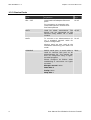
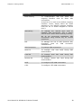
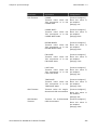
1.2.3 Device LED
Name
Status
Explanation
Power LED
On
Device is receiving power from the
source normally
Off
Device is off or not receiving power
from the source normally
Flickering
Device
is
currently
read/write operations
Off
Device is not performing
read/write operations
On
Corresponding network port (FE0 –
FE7) is connected to a network
Flickering
Data is being transmitted via the
corresponding network port (FE0 –
FE7)
Off
Corresponding network port (FE0 –
FE7) is not connected to a network
Read/Write LED
Network Port LED
performing
any
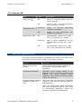
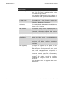
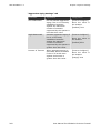
1.3 What can SifoWorks Do?
The main functions provided by SifoWorks are listed in the table below.
Each function is described in detail in the following sections.
Function
Description
Status based access
control
Status-based access control realized via
the security chip embedded within
SifoWorks.
Dynamic port analysis
SifoWorks uses a Helper module on the
application layer to perform dynamic port
analysis. The module supports various
application layer protocols including RTSP,
H.323, FTP, PPTP etc.
Internal address masking
capability via NAT and
PAT
Using NAT and PAT techniques, SifoWorks
is able to mask internal network structure
and addresses.
Users can define SNAT, DNAT and double
NAT rules. SifoWorks selects the port using
an optimization algorithm, raising the
utilization of ports and IP addresses.
User Manual for SifoWorks D-Series Firewall
5
OD1300UME01-1.3
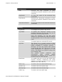
Chapter 1 Product Overview
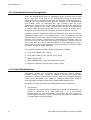
Function
Description
Intelligent Protocol
Recognition
Intelligent protocol recognition effectively
identifies and controls applications that
attempt to communicate with the network
via a non-standard port.
For example, the function can prevent
services using a protocol other than HTTP
from connecting to the network over port
80, controlling downloads using P2P clients
or IM messaging etc.
DOS/DDOS defense
SifoWorks defends the network against
DOS/DDOS attacks by:
z
Using the SYN cookie mechanism to
perform authentication for TCP-based
applications
z
For applications based on other protocols,
SifoWorks uses a mechanism based on
the source IP address
Content filter
SifoWorks supports the filtering of data on
the application layer for the HTTP, email
and FTP protocols
Rich routing capabilities
SifoWorks provides rich routing capabilities
including:
z
3rd layer route forwarding
z
Support for multi-gateway routing
z
Ensuring the continuity of data packets
using route mirroring technology
High performance VPN
engine
SifoWorks provides a high performance
VPN engine, supporting IPsec VPN, PPTP
and L2TP
Multi-gateway access and
load balancing
SifoWorks provides a multi-gateway access
function along with load balancing for
connections and servers.
The system establishes an independent
tunnel for IPsec VPN, providing security
and redundancy for connections between
branch networks without compromising the
firewall’s performance. This ensures that
information can be transmitted securely
within the company.
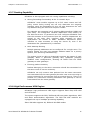
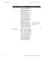
6
Comprehensive, multilevel flow control
SifoWorks helps to achieve comprehensive
flow control by combining SifoWorks’ IP
rate limit function together with IRP
(Intelligent Recognized Protocols) and QoS.
High Availability (HA)
SifoWorks supports the high availability
(HA) mode: AS (Active-Standby)
User Manual for SifoWorks D-Series Firewall
Chapter 1 Product Overview
OD1300UME01-1.3
1.3.1 Status-based Access Control
Status based access control over packet transmission within a network is
the firewall’s basic functionality. This is achieved using a high density
security chip embedded within SifoWorks. When SifoWorks receives a
packet, it first checks if there is any session information corresponding to
this packet. The system then decides whether to forward this packet
directly or continuing matching it against the security rules based on the
result of this check.
Session establishment for TCP transmission requires a three-way
handshake. A similar mechanism is used for other protocols such as UDP
and ICMP. Status based control over sessions reduces network attacks
and enables SifoWorks to dynamically allow related connections to pass
through the system.
1.3.2 Dynamic Interface Analysis
Certain protocols establish multiple independent data links. For example,
the FTP protocol establishes separate data tunnels and command tunnels.
First, a command tunnel is established. When users send a file request
command via this tunnel, the FTP server and client negotiate the data
tunnel’s attributes, including source and destination interfaces, via the
command tunnel. A data tunnel will then be established between server
and client. Since the source and destination interfaces are dynamically
assigned, the firewall cannot be pre-configured to accept such
connections. Furthermore, the firewall must also be able to accept all
related connections.
SifoWorks’ Helper module effectively identifies the attributes of related
connections and notifies the security chip to establish a sub data link.
Packets received by SifoWorks through the data tunnel will thus be
accepted. The Helper module also performs NAT on the packet’s payload.
SifoWorks’ Helper module includes support for various application layer
protocols such as RTSP, H.323, FTP, PPTP etc.
1.3.3 Internal Address Masking Capability Based on NAT and PAT
For most enterprises, the number of public IP addresses allocated is far
less than the number required to assign an IP to each internal PC. Also,
enterprises want to mask their internal IP addresses to avoid exposing
their internal network structure to attacks by hackers. SifoWorks resolve
the above 2 issues using the NAT and PAT technologies.
SifoWorks allows users to define SNAT, DNAT and Double NAT rules, using
an optimization algorithm to enhance the utilization of ports and IP
addresses.
User Manual for SifoWorks D-Series Firewall
7
OD1300UME01-1.3
Chapter 1 Product Overview
1.3.4 Intelligent Protocol Recognition
There are standardized ports for application layer services such as port
80 for HTTP, port 21 for FTP etc. For enterprises wishing to restrict their
employees from accessing the Internet, the simplest method would be to
close port 80, thus denying HTTP packets. However, new developments
now enable users to customize the port number used for HTTP
applications. Furthermore, several P2P software dynamically determines
which port number to use. Thus, allowing and denying the transmission
of specific data through the firewall is now no longer a simple issue.
SifoWorks thus introduces an intelligent protocol recognition function.
Intelligent protocol recognition effectively identifies and controls services
transmitting data over a non-standard port, such as replacing port 80
with port 90 for HTTP. This enforces effective control over the use of such
services. For example, preventing the transmission of packets sent via
port 80 but are not using the HTTP protocol effectively restricts services
from using port 80 such as P2P downloads and IM messaging. Using a
port/protocol system, the intelligent protocol recognition function is able
to identify and block illegal data flow.
This function supports a wide number of protocols including:
z
HTTP, FTP, SOCKS, SSH, Telnet
z
TFTP, VNC, RTSP, H.323, SIP, IM_HTTP_Proxy
z
SMTP, POP3, IMAP
z
AIM, MSNMessenger, QQ, YahooMessenger, Popo
z
Bittorrent, Edonkey, MUTE, FOXY, Kugoo, Xunlei
1.3.5 DoS/DDoS Defense
DOS/DDOS attacks are a common threat faced by network security
systems. Using viruses, trojans or malwares, hackers can manipulate
machines to initiate such attacks by simply sending a command. Network
usage will be disrupted if the firewall is unable to differentiate between
such machines and legal users when a DOS/DDOS attack occurs.
SifoWorks provides the following DOS/DDOS defense mechanisms:
z
TCP protocol
SifoWorks uses a SYN cookie mechanism to perform authentication. A
packet is identified as a legal data flow if it is successfully
authenticated via this mechanism. The system will then check the
packet against sessions or rules. Otherwise, the packet is identified as
an illegal data flow and dropped.
8
User Manual for SifoWorks D-Series Firewall
Chapter 1 Product Overview
z
OD1300UME01-1.3
UDP and other protocols
SifoWorks uses an overall record mechanism based on source IP. Each
record includes the connection speed, total connection number, traffic
etc. SifoWorks allows for more than 1M of source IP records.
For example, 2 web servers, providing HTTP services of up to 200M
each are set up in the network. When a hacker initiates a DOS/DDOS
attack on the server, the large amount of fake IP rapidly takes up the
server’s bandwidth, thus denying other accesses to the servers. When
SifoWorks’ DOS/DDOS defense is deployed, the system restricts all
connections from the fake IPs, thus ensuring that the server has
sufficient bandwidth to provide services to legal users.
With the two mechanisms above, SifoWorks greatly reduces the threat of
DOS/DDOS attacks.
SifoWorks is able to detect and protect your network against the following
types of attacks:
z
SYN Flood
z
TCP scan
z
Ping Sweep
z
Ping Flood
z
UDP Flood
z
UDP scan
z
ARP Attack
z
TearDrop
z
Bonk
z
Boink
z
Nestea
z
Newtear
z
Syndrop
z
Jolt2
z
Oshare
z
1234
z
Ping of death
z
Saihyousen
z
Smurf Attack
z
Land-based Attack
z
WinNuke
User Manual for SifoWorks D-Series Firewall
9
OD1300UME01-1.3
Chapter 1 Product Overview
1.3.6 Content Filter
Traditional firewalls support access control on the TCP/IP layer but not on
application layer data. Packets with legitimate TCP and IP information but
containing illegitimate data will still be allowed to pass through the
network.
Therefore, other than control over packets on the TCP/IP layer,
enterprises also wish to filter packets based on application data.
SifoWorks supports application layer content filtering for the following
protocols:
z
HTTP
SifoWorks supports filtering of HTTP content based on URL,
commands, and keywords; is able to restrict multi-thread
downloading and supports removal of scripts such as Active-X,
Javascripts, Java applet and cookie.
z
Email
SifoWorks supports email content filtering based on SMTP server,
recipient mail addresses, sender mail addresses, email subject, mail
body keywords, mail attachment, mail size and the number of
recipients.
z
FTP
SifoWorks supports the filtering of FTP data based on file name,
keywords and commands. Multi-thread downloading of FTP files can
also be denied.
10
User Manual for SifoWorks D-Series Firewall
Chapter 1 Product Overview
OD1300UME01-1.3
1.3.7 Routing Capability
SifoWorks is also equipped with rich routing capabilities including:
z
Strong forwarding functionality at the 3rd network layer
SifoWorks’ route module supports up to 512 static routes and 247
policy routes. Policy routing can not only determine the outgoing
interface using the destination IP, but can also determine the next
hop address using the source IP and port number.
For example, an enterprise has 2 outgoing WAN interfaces (ADSL and
optic fiber). The enterprise’s research department relies heavily on
the Internet service. IT personnel can thus configure SifoWorks such
that the accesses to the Internet from the research department are
routed to the optic fiber interface while accesses by other
departments are routed to ADSL. SifoWorks determines which
interface to route accesses to using the source IP, even if the
destination URL (destination IP) is identical.
z
Multi-Gateway Routing
Multiple gateway addresses can be configured for a single route. The
system selects the next hop gateway address based on a priority
system, thus achieving load balancing.
The system must be able to dynamically monitor the status of each
gateway. When a particular gateway fails, SifoWorks promptly
modifies route configurations, directing all traffic from the failed
gateway to other gateways.
z
Ensuring packet continuity
Packets belonging to the same connection should be transmitted via
the same route to ensure continuity.
SifoWorks not only ensures that packets from the same connection
are transmitted via the same gateway but also uses route mirroring to
ensure continuity for connections from an external source. That is, all
packets of a connection entering SifoWorks from gateway A will be
transmitted from the same gateway.
1.3.8 High Performance VPN Engine
SifoWorks’ high performance VPN engine supports IPsec VPN, PPTP VPN
and L2TP VPN.
The system supports the DES, 3DES and AES encryption algorithms, MD5
and SHA1 authentication algorithms. The DES and AES modules are
equipped with up to 200Mbps processing capability.
IPsec VPN also supports AH, ESP and AH+ESP modes.
User Manual for SifoWorks D-Series Firewall
11
OD1300UME01-1.3
Chapter 1 Product Overview
1.3.9 Multi-Gateway Access and Load Balancing
Using its routing function (“1.3.7 Routing Capability”), SifoWorks is able
to support multi-gateway access. This in turn equips SifoWorks with the
capability of achieving load balancing between multiple connections and
servers.
As the system establishes independent tunnels for IPsec VPN, it provides
security and redundancy for connections between the company’s branch
networks without compromising the firewall’s performance. This ensures
that information can be transmitted securely within the company.
SifoWorks is also able to balance traffic load among multiple servers via
DNAT (Destination Network Address Translation) rules. For example,
multiple Web servers are set up to provide services externally at the
same time. Using a round-robin or priority weight system, SifoWorks can
distribute traffic among these servers. A “Sticky” option is also available
in SifoWorks, ensuring that requests from the same host are processed
by the same server.
z
Round-robin
External connection requests will be assigned to the servers in a
round-robin manner. If “Sticky” is enabled, the system will establish a
relationship between source and destination addresses using the hash
algorithm. The connection is then assigned to the next available
server.
z
Priority weight
All servers are assigned with a priority weight value. External
connection requests are then distributed to the servers according to
their priority. Servers with larger priority weight will be assigned with
a larger number of requests.
1.3.10 Comprehensive Flow Control
SifoWorks IP rate limit can operate in conjunction with the IRP
(Intelligent Recognized Protocols) and QoS functions, providing a wellrounded flow control comprising of 3 layers:
12
z
Enable IRP and QoS functions in filter rules to achieve overall flow
control based on protocols.
z
In the IP rate limit function, define a “Subnet” type limit. This
achieves a 2nd level of flow control for entire subnets.
z
In the IP rate limit function, define “Host” type limits to achieve flow
control over individual hosts.
User Manual for SifoWorks D-Series Firewall
Chapter 1 Product Overview
OD1300UME01-1.3
1.3.11 High Availability (HA)
SifoWorks includes a HA function to ensure network reliability supporting
the HA-AS (Active Standby) mode.
In AS mode, configuration information such as rules, objects, routes and
sessions will be synchronized on both master and slave device. When the
master device fails, all network services will be automatically re-directed
to the slave device.
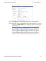
1.4 System Specifications
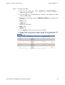
1.4.1 Device Performance and Capacity
The following table lists the various performance and capacity indexes of
the SifoWorks device.
Index
Value
Firewall Performance
z
D100 – 200Mbps
z
D200 – 450Mbps
z
D300 – 600Mbps
z
D100 – 150Mbps
z
D200/D300 – 200Mbps
VPN Performance
Number of Concurrent
Sessions
1,200,000
Session Establishment Rate
per Second
6,000
Number of Security Policies
z
D100 – 4000
z
D200/D300 – 8000
Number of Customizable
Security Domains
8
Packet Latency
5µs – 13µs
User Manual for SifoWorks D-Series Firewall
13
OD1300UME01-1.3
Chapter 1 Product Overview
1.4.2 Device Dimensions
The following table details the physical dimensions of the SifoWorks
device.
Index
Value
Length x Breadth
x Height
428mm x 358mm x 47mm
Weight
5kg
1.4.3 Power
The following table lists the power supply requirements of the SifoWorks
device.
Index
Value
Voltage
90V – 260V
Frequency
50Hz – 60Hz
1.4.4 Operating Environment
The physical operating environment requirements of the SifoWorks device
are detailed in the table below.
Index
Value
Operational Temperature
0ºC – 40ºC
Non-operational Temperature
-10ºC – 70ºC
Humidity
10% – 90%
1.4.5 Reliability Index
The following table shows the reliability index of the SifoWorks devices.
14
Index
Value
MBTF (Mean Time Between Failure)
100,000h
User Manual for SifoWorks D-Series Firewall
2
Chapter
Getting started
2
This chapter comprises of the following sections:
z
SifoWorks Deployment Topology
Explains the three commonly used deployment modes of SifoWorks
z
Basic System Operations
Describes the basic SifoWorks operations including system login and
logout. This section also describes the procedure to add, edit and
delete records where a record refers to an object, administrator
account, filter rule etc. that is stored and displayed using lists on the
system.
z
SifoWorks User Interface
Describes the SifoWorks UI (user interface) and the various system
menu options
z
Task List
Lists the various tasks a SifoWorks administrator may need to
perform when managing the system and network activities.
z
Device Quick Configuration Guide
Displays a flowchart and brief explanation on how to deploy and
configure your SifoWorks device to provide basic functionality in your
existing network.
User Manual for SifoWorks D-Series Firewall
15
OD1300UME01-1.3
Chapter 2 Getting started
2.1 SifoWorks Deployment Topology
By selecting different work mode for the SifoWorks system, you can
deploy SifoWorks using one of three modes: Transparent mode, route
mode and hybrid mode. Each of these modes is explained in detail below.
Note:
Please refer to “3 Network Configuration” for information on setting up
SifoWorks working mode and other network parameters.
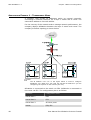
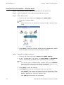
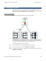
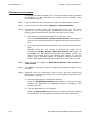
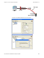
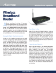
2.1.1 Transparent Mode
Transparent mode is suitable for networks that do not require routing or
NAT address translations. All devices directly connected to SifoWorks are
located within the same network domain. An example would be deploying
SifoWorks between a router and a layer 3 switch. In this mode, no
modifications to the existing network settings are necessary. NAT or
routing via SifoWorks is not required for local network devices.
An example of a network topology deploying SifoWorks in transparent
mode is shown below.
16
User Manual for SifoWorks D-Series Firewall
Chapter 2 Getting started
OD1300UME01-1.3
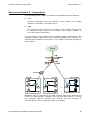
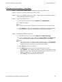
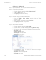
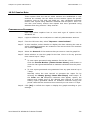
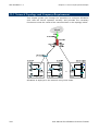
2.1.2 Route Mode
Route mode is suitable for networks that are made up of multiple
domains, with each domain using a different network segment. All data
transmitted between devices in different domains must pass through
SifoWorks for routing or NAT. The figure below shows an example of a
network topology deploying SifoWorks in route mode.
User Manual for SifoWorks D-Series Firewall
17
OD1300UME01-1.3
Chapter 2 Getting started
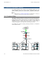
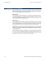
2.1.3 Hybrid Mode
Hybrid mode is suitable in networks that are made up of 2 or more
network domains, where some domains are from different network
segments. Data transmission between domains in different network
segments is handled in the same way as in route mode. The handling
mechanism for data transmission for domains within the same network
segment is identical to that for transparent mode.
An example network topology with SifoWorks deployed in hybrid mode is
shown below:
18
User Manual for SifoWorks D-Series Firewall
Chapter 2 Getting started
OD1300UME01-1.3
2.2 Basic System Operations
2.2.1 System Login
After deploying SifoWorks in your network, SifoWorks administrators can
login to the system’s UI via the Internet Explorer browser (version 6.0 or
later) or the Mozilla Firefox browser (version 1.5 or later).
SifoWorks supports 2 login methods:
z
Traditional Login
Logging into the system via user name and password
z
OTP (One Time Password) Login
Uses a one time password to login to the system. The system
computes a response string based on password and a dynamically
generated challenge string. User password will not be transmitted
over the network, thus ensuring user security.
Note:
OTP login can only be used by users whose account is configured with the
“allow OTP login” attribute and JRE (version 1.6.0 or later) is installed on
the host used to access SifoWorks.
You can request for a login administrator account from the system’s
default administrator (using the “admin” account). Whether your account
is allowed to login via OTP depends on your account settings added by
the default administrator.
Users can login to SifoWorks only if it is within their account’s validity
period.
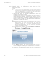
CONFIGURATION PROCEDURE – TRADITIONAL LOGIN
Step 1
Activate your web browser on the administrative PC.
Your administrative PC must be able to access the network where
SifoWorks is deployed in. If your PC is directly connected to SifoWorks via
a cross-over cable, please ensure that your PC’s IP address is within the
same subnet as the IP address of SifoWorks’ administrative interface.
Step 2
In the address bar, enter SifoWorks’ administrative IP address.
If this is the initial login to the system via the management port, please
enter the factory default address “https://172.16.0.1” in your web
browser. For information on modifying SifoWorks’ administrative IP
address, please refer to “3.2 Setting up the Basic Network Settings”.
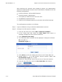
Step 3
A login dialog window will appear. Enter your user name and password in
the respective textboxes.
Step 4
Click [Login] to login to the system.
User Manual for SifoWorks D-Series Firewall
19
OD1300UME01-1.3
Chapter 2 Getting started
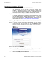
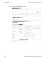
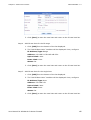
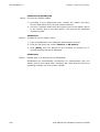
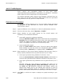
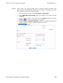
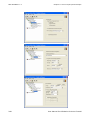
CONFIGURATION PROCEDURE – OTP LOGIN
Step 1
Activate your web browser on the administrative PC.
Your administrative PC must be able to access the network where
SifoWorks is deployed in. If your PC is directly connected to SifoWorks via
a cross-over cable, please ensure that your PC’s IP address is within the
same subnet as the IP address of SifoWorks’ administrative interface.
Step 2
In the address bar, enter SifoWorks’ administrative IP address.
If this is the initial login to the system via the management port, please
enter the factory default address “https://172.16.0.1” in your web
browser. For information on modifying SifoWorks’ administrative IP
address, please refer to “3.2 Setting up the Basic Network Settings”.
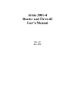
20
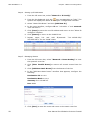
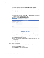
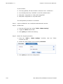
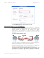
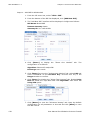
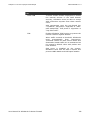
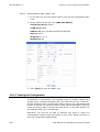
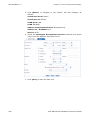
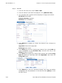
Step 3
A login dialog window will appear. Enter your user name and select “OTP
User”.
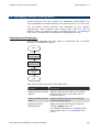
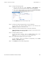
Step 4
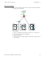
A challenge string will be generated and displayed. Copy the string of
characters between “otp-md5” and “ext” into the Challenge textbox
below. For example, the challenge value is “498 lo1” in the figure below.
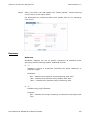
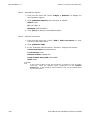
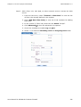
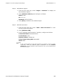
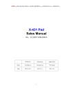
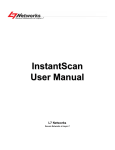
Step 5
Enter your account Password.
Step 6
Click [compute with MD5]. The system will generate a string of
characters in the One-Time Password textbox below.
Step 7
Copy the one-time password generated into the Response textbox
above. Click [Login] to login to SifoWorks
User Manual for SifoWorks D-Series Firewall
Chapter 2 Getting started
OD1300UME01-1.3
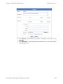
2.2.2 System Logout
From the administrative interface, select “Logout” from the left or click
from the top right corner of the page.
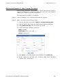
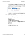
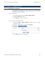
2.2.3 Add Record
This section explains how to add a record, such as an administrator
account, an address object, a service object or a filter rule etc. into the
system.
Note:
This section gives an overall explanation to the procedure to add a record
entry into the system. For detailed information on the various kinds of
records that can be added, please refer to the appropriate sections later
in this manual. For example, you can refer to “9.2 Managing
Administrator Accounts” for information on user account records or “4.2
Managing Filter Rules” for details on filter rule records.
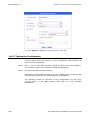
CONFIGURATION PROCEDURE
Step 1
Navigate to the configuration page for the particular type of record from
the left menu bar.
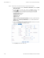
Step 2
Click [Add XX], (XX depends on the type of record you are adding).
Step 3
In the “Add XX” interface displayed, configure the settings accordingly.
Step 4
Click [Save]. The system will add a new record to the corresponding list.
User Manual for SifoWorks D-Series Firewall
21
OD1300UME01-1.3
Chapter 2 Getting started
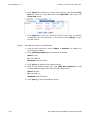
2.2.4 Edit Record
This section explains how to edit an existing record.
Note:
This section gives an overall explanation to the procedure to modify a
record entry in the system. For detailed information on the various kinds
of records, please refer to the appropriate sections later in this manual.
For example, you can refer to “9.2 Managing Administrator Accounts” for
information on user account records or “4.2 Managing Filter Rules” for
details on filter rule records.
CONFIGURATION PROCEDURE
Step 1
Navigate to the configuration page for the particular type of record from
the left menu bar.
Step 2
From the record list, click the
record to be modified.
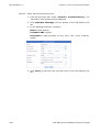
Step 3
From the configuration interface displayed, modify the settings as
required.
Step 4
Click [Save] to save the changes. A success message should be
displayed by the system.
icon in the row corresponding to the
2.2.5 Delete Records
This section explains how to delete a system record.
Note:
This section gives an overall explanation to the procedure to delete a
record entry from the system. For detailed information on the various
kinds of records, please refer to the appropriate sections later in this
manual. For example, you can refer to “9.2 Managing Administrator
Accounts” for information on user account records or “4.2 Managing Filter
Rules” for details on filter rule records.
CONFIGURATION PROCEDURE
22
Step 1
Navigate to the configuration page for the particular type of record from
the left menu bar.
Step 2
From the record list, click the
record to be deleted.
Step 3
From the confirmation popup window, click [OK] to delete the record and
refresh the list.
icon in the row corresponding to the
User Manual for SifoWorks D-Series Firewall
Chapter 2 Getting started
OD1300UME01-1.3
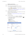
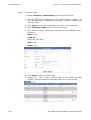
2.3 SifoWorks User Interface
Upon successful login, the SifoWorks administrative UI will be displayed.
SifoWorks’ web UI includes 3 areas:
z
Toolbar
The toolbar is located at the top right corner of the interface and
includes several buttons:
−
−
: Opens a new window loading O2Security’s home page
(http://www.o2security.com)
−
: Opens a new window loading the authentication website
(http://www.us-cert.gov/)
−
: Navigate to the “System Configuration” interface to select
the UI’s display language
−
z
: Opens a new window displaying the system’s online help
: Logout of the SifoWorks system
Menu Bar
The leftmost column of this interface is the menu bar. You can
navigate to the configuration/monitoring interfaces of the various
system functions by selecting the corresponding menu options. The
tables later in this section briefly explain each option.
User Manual for SifoWorks D-Series Firewall
23
OD1300UME01-1.3
Chapter 2 Getting started
z
Operation Window
The right frame of the web UI is the operation window where you can
configure the system, monitor network activities etc. Detailed
information regarding the various system functions can be found in
the later chapters of this manual.
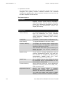
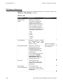
The Menu Options
Menu: Home
-
Displays various system status information
and recent alerts. You can select to manually
refresh the displayed information or set up
the system to automatically refresh the
display periodically.
Menu: System
Admin Setting
To management the user accounts that can
login to SifoWorks UI. This includes
adding/deleting accounts, managing account
access authority, managing login security
attributes etc.
Config File
To import or export system configuration file.
Patch Setting
To upgrade SifoWorks’ software version.
Common Setting
To configure the system’s basic settings such
as web timeout, UI language, system date
and time, web server CA etc.
This interface also allows you to reboot your
device or reset the device’s settings to
factory default.
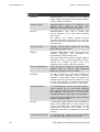
SNMP Setting
If you want to manage SifoWorks using a
network management system, you must use
this interface to complete the SNMP proxy
configuration. “SNMP Trap” and “Auth
Server” are optional configurations.
SNMP Trap
Set up SNMP Trap so that SifoWorks alerts
the specified server if abnormalities in the
device status are detected.
Timeout Setting
Specify timeout values for various SifoWorks
operations including timeout for ICMP, TCP,
UDP connections etc.
Registration Server
Specify the server where a network
management system will automatically
discover this device for management.
You must first enable and configure “SNMP
Setting” for this function to operate properly.
24
User Manual for SifoWorks D-Series Firewall
Chapter 2 Getting started
OD1300UME01-1.3
Auth Server
To configure external authentication servers,
customize the authentication interface and
related security settings.
Other than the default local authentication
method, SifoWorks also supports the use of
RADIUS, LDAP and AD authentication servers
to authenticate users.
Auth Address
Manage the address range of authentication
users
and
the
authentication
server
associated to each range.
A user will only be authenticated by the
authentication server if his IP address is
within the associated address range.
Auth User
Manage the list of authentication users. You
can define three types of authentication
users: filter rule, L2TP and PPTP.
Auth Group
To manage
groups.
authentication
users
using
Menu: Wizard
VPN Wizard
A step-by-step wizard to set up a basic pointto-point IPsec VPN connection.
Filter Rule Wizard
A step-by-step wizard to add a filter rule.
Menu: Monitor
Session
To view session information including source
IP, destination IP, protocol, established time
etc. for each session. You can also manually
terminate selected sessions from this
interface.
Online User
To view all currently online users who have
been
successfully
authenticated.
The
information displayed includes user name,
source IP, online time, and authentication
server. You can also manually disconnect
users from this list.
DHCP Lease
To view all IP addresses assigned to client
ends by DHCP servers, the corresponding
MAC addresses, starting and ending time of
the lease etc.
DHCP servers refer to the DHCP servers
specified on SifoWorks’ network configuration
interface.
User Manual for SifoWorks D-Series Firewall
25
OD1300UME01-1.3
Chapter 2 Getting started
Menu: Object
Address
Add/edit/delete an IP address or IP address
range object to facilitate the creation of filter
rules or VPN connections.
Address Group
Add/edit/delete a group of IP address or IP
address range object to be used when
defining filter rules or VPN connections.
Service
Add/edit/delete TCP, UDP or ICMP type
service objects to be used when defining
filter rules.
By default, the system defines several
hundred commonly used services. You can
add new services customized to your network
requirements.
Service Group
Manage service group objects to be used
when defining filter rules.
MapList
To add a table object made up of a series of
address mappings. This facilitates the
formulation of source NAT rules.
Each map table can contain multiple address
mappings. Hence, using map tables help to
reduce the number of NAT rules. This
optimizes the system’s NAT performance.
Server Load Balance
These objects are applied on destination NAT
(DNAT) rules to achieve load balancing
between multiple servers via DNAT.
Schedule
To add a recurring or one-time schedule to
be used when defining weekly schedule
objects or to be used in filter rules directly to
control the time period during which the rule
is valid. For example, you can add a schedule
to only enable a filter rule from 1-3pm daily.
Weekly Schedule
To add/edit/delete weekly schedule objects.
These objects can be used when defining
filter rules to control the time rules are valid.
For example, you can set up a rule to be
valid only between 1pm-3pm every Monday.
You must use schedule objects when defining
weekly schedule objects.
26
IP Pool
To manage IP pool objects, each containing a
range of IP addresses. IP pool objects are
used to facilitate the configuration of VPN
connections (specifies the range of IP
addresses that can be assigned to the VPN
clients).
Content Filtering Obj
To manage URL, email or keyword objects
used in defining content filtering rules.
User Manual for SifoWorks D-Series Firewall
Chapter 2 Getting started
OD1300UME01-1.3
Menu: Network
Virtual Port Config
To group SifoWorks’ data ports into three
virtual ports.
VLAN Setting
To add and configure VLANs according to
your network topology.
IP Config
To configure the IP address for each VLAN.
You can also modify the administrative IP of
SifoWorks from this interface.
Route Setting
To add static and policy routes
DHCP Setting
To set up SifoWorks as a DHCP server or to
specify DHCP relay servers to provide DHCP
services.
PPPoE Setting
To configure SifoWorks such that it is able to
establish a connection to external networks
via PPPoE.
Note that you must enable PPPoE mode from
the “Advance > PPPoE Mode” interface.
IP-MAC Binding
To manage IP to MAC binding pairs. This
enhances security by preventing the misuse
of IP addresses by illegal hosts.
ARP Setting
To manage the system’s ARP table including
static ARP and dynamic ARP tables. This
reduces security risks caused by ARP
spoofing or IP spoofing.
From this interface, you can manually add
static ARP records or select the records from
the dynamic ARP table and add them to the
static ARP table.
DNS Setting
To specify the IP addresses of the DNS
servers. This equips SifoWorks with domain
name resolution capability.
DDNS Setting
To establish connection with DDNS (Dynamic
Domain Name System) servers to provide
the DDNS service. This allows users to
establish dynamic VPN connections via
PPPoE.
User Manual for SifoWorks D-Series Firewall
27
OD1300UME01-1.3
Chapter 2 Getting started
Menu: Firewall
Filter Rule
To manage a list of filter rules customized
according to your network requirements.
These rules filter data transmitted through
the firewall’s data ports.
Local Rule
To define local rules used to control access to
the SifoWorks system via data ports. These
rules restrict administrative accesses to the
firewall.
NAT Rule
To add source or destination NAT rules,
translating source or destination addresses of
specific data packets.
To apply maplist objects to source NAT rules
or server load balancing objects in
destination NAT rules, you must create the
corresponding objects from the “Object >
MapList” or “Object > Server Load Balancing”
interfaces first.
Content Filtering
To manage a list of content filtering rules set
up according to the company requirements,
filtering data on the application layer that are
allowed to pass through SifoWorks.
Menu: IDP
Network Variables
To differentiate
external networks
Rule Group Control
To enable/disable all rules or a subset of
rules within each IDP rule group. You can
also modify the attributes of each rule.
User-Defined Rules
To define IDP rules customized according to
your company’s needs.
Rule Upgrade
To upgrade the set of IDP rules.
Upgrade Setting
To configure the system such that it is able
to perform IDP rule upgrade operations.
between
internal
and
The system automatically downloads the
upgrade file from an O2Security server.
You can set up an email address before
executing a rule upgrade. Any alert
messages generated due to an upgrade
failure can then be sent to this email
address.
28
Preprocessors
To
enable
and
set
up
the
IP
Defragmentation, TCP Stream Reassembly or
Port Scan preprocessors.
IDP Control
To select IDP working mode.
User Manual for SifoWorks D-Series Firewall
Chapter 2 Getting started
OD1300UME01-1.3
Menu: VPN
IPsec Setting
To enable/disable
outgoing interface
connections.
VPN and
used for
select the
IPsec VPN
Virtual Port 2 is used as the default outgoing
interface. Hence, simply select the VLAN
assigned to the desired outgoing interface
from the list of VLANs assigned to Virtual
Port 2.
Manual Key
To manage the manual keys used to
establish VPN connections. This is mainly
used to test if IPsec VPN is working correctly.
We do not recommend establishing VPN
connections using manual key for normal
operations.
IKE
To manage the list of IKE (Internet Key
Exchange)
used
for
VPN
connection
establishment.
VPN Connection
To manage VPN connections.
Root CA
To manage root
authentication.
CAs
used
during
IKE
Local CA
To manage local
authentication.
CAs
used
during
IKE
Remote CA
To manage remote CAs used during IKE
authentication.
PPTP
To configure PPTP VPN connections.
L2TP
To configure L2TP VPN connections.
User Manual for SifoWorks D-Series Firewall
29
OD1300UME01-1.3
Chapter 2 Getting started
Menu: Advance
QoS Setting
To define QoS priority levels for each virtual
port. This can then be applied to filter rules
to enable the QoS service.
You can also enable/disable QoS and set up
the maximum and guaranteed bandwidth for
each virtual port.
IP Rate Limit
To enable the IP limit function, limiting the
upload and download speeds available for an
individual IP address or a subnet.
HA Setting
To enable/disable HA between two SifoWorks
device. Two SifoWorks devices work in AS
mode if HA is enabled.
IDS Linkage
To provide IDS by setting up the system to
link SifoWorks with a third party IDS device.
Currently, SifoWorks supports IDS devices
from Venus and NSFOCUS.
IDS Setting
To set up SifoWorks’ own IDS function.
PPPoE Mode
Select the PPPoE mode to enable SifoWorks
to connect to external networks via PPPoE.
After enabling PPPoE here, you must then
configure the PPPoE settings accordingly
from the “Network > PPPoE Setting”
interface.
IRP Upgrading
To import an upgrade file to update the IRP
(Intelligent Recognition Protocol) module.
IRP recognizes which protocol is being used
by a particular connection. Applying IRP on
filter rules and QoS allows the system to
block or limit traffic from specific protocols.
However, network protocols are constantly
evolving. Hence, for IRP to be effective, the
system’s IRP module should be regularly
updated to recognize new or modified
protocols.
You can obtain the IRP upgrade patch from
O2Security.
30
User Manual for SifoWorks D-Series Firewall
Chapter 2 Getting started
OD1300UME01-1.3
Menu: Diagnostics
Ping
Executes the Ping command to check
connectivity between SifoWorks and external
networks.
Ping Result
To view the result of the executed Ping
commands.
Trace Route
Executes the Traceroute command to check
connectivity between SifoWorks and external
networks.
Trace Route Result
To view the result of the executed traceroute
commands.
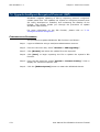
Menu: Log
Log Server
To configure the system’s log server.
Log Global
To specify the maximum number of log
entries to store for each log type. Also set up
the policy for deleting log entries.
From this interface, you can also select
whether to record DNS log, ICMP log and log
all data packets that do not match any filter
rules.
Log Export
To export logs to an external FTP server.
Log Filter
This allows you to specify criteria to filter
logs (for each log type) that are to be stored
locally (LocalDB) or remotely (Server1 –
Server4). You can also specify filter criteria
to select the logs that are to be sent via
email (EmailAlert) or exported to a FTP
server. This allows you to select to store only
the necessary logs.
The
system
further
enhances
user
convenience
when
viewing
logged
information by allowing you to specify the
format of logs for each log type.
Email Alert
To enable and set up the log email alert
function including configuring the email
address to receive log files, the time interval
between each mail send etc.
Admin Log
To search and view administrative logs.
System Log
To search and view system logs.
Security Log
To search and view security logs.
Traffic Log
To search and view traffic logs.
User Manual for SifoWorks D-Series Firewall
31
OD1300UME01-1.3
Chapter 2 Getting started
Menu: Reporter
Reporter Setting
To enable/disable the report monitoring
function and select the elements to be
monitored.
System Status
To view current and history firewall status
report including CPU status, content status
and Ramdisk status information.
Traffic
To view current and history reports on traffic
flow for each data port including each port’s
outgoing, incoming and total traffic flow.
IP Traffic Statistics
To view statistical reports on traffic for each
IP address. These reports allow you to
understand the upload speed, download
speed and total traffic generated by each IP
address.
You can click the icon on the report to
navigate to the interface where you can
change the traffic limit for a particular IP
address.
Session Number
To view current and history reports on the
number of system session. You can also view
the distribution of sessions based on
protocols used.
Session Rate
To view current and history reports showing
the rate of session establishment (in
seconds).
Menu: Logout
-
32
To logout from SifoWorks.
User Manual for SifoWorks D-Series Firewall
Chapter 2 Getting started
OD1300UME01-1.3
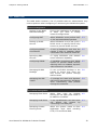
2.4 Task List
The table below contains a list of possible tasks an administrator may
need to perform when configuring or monitoring the SifoWorks system.
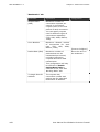
Network Configuration
Setting up the Basic
Network Settings
During the installation of SifoWorks
or when you need to modify
network configurations.
3.2
Configuring NAT
When SifoWorks must perform NAT
on the transmitted data packets.
3.3
Setting up DHCP
Service
When SifoWorks is to be set up as a
DHCP server or specify DHCP relay
servers to provide DHCP services.
3.4
Configuring PPPoE
Connections
To set up SifoWorks such that the
system is able to establish PPPoE
connections with external networks.
3.5
Specifying DNS
Servers
To equip SifoWorks with domain
name resolution capability.
3.6
Configuring DDNS
To establish connections with DDNS
servers to provide DDNS service,
allowing users to establish dynamic
VPN connections via PPPoE.
3.7
Managing IP-MAC
Bindings
To set up IP-MAC bindings in the
system to ensure that users can
only access the system through
allowed hosts.
3.8
Managing the ARP
Tables
To manage the static and dynamic
ARP entries generated by SifoWorks
when transmitting data packets
through the networks.
3.9
Managing Filter Rules
When filter rules for packets
arriving at the data ports need to
be added or modified.
4.2
Managing Local Rules
To set up SifoWorks such that users
can
access
the
system
by
connecting via a data port.
4.3
Managing Content
Filtering Rules
When the system needs to filter
application layer data including
HTTP, FTP and Email data.
4.4
Firewall Rule Management
User Manual for SifoWorks D-Series Firewall
33
OD1300UME01-1.3
Chapter 2 Getting started
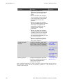
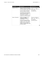
Intrusion Detection and Prevention (IDP)
Configuring and
Enabling IDP
When IDP is to be activated on
SifoWorks.
5.2
Upgrade IDP rules
When the SifoWorks system’s IDP is
based on the Snort system and you
need to update the Snort version.
5.3
Configuring IPsec VPN
Connections
When you want to configure a siteto-site VPN connection or set up an
IPsec VPN connection for remote
accesses.
6.2
Configuring PPTP VPN
Connections
When you want to add PPTP VPN
connections.
6.3
Configuring L2TP VPN
Connections
When you want to configure L2TP
VPN connections.
6.4
Setting Up QoS
Services
When you want to enable QoS,
specifying
maximum
and
guaranteed bandwidth to ensure
quality of service for all data traffic
transmitted through the firewall.
7.2
Limiting IP Traffic
To enable IP limit function such that
the system restricts the upload and
download speeds for specific IP
addresses or subnets.
7.3
Activating High
Availability
When two SifoWorks devices are to
be set up in HA to ensure system
reliability.
7.4
Configuring IDS
Services
To activate SifoWorks’ IDS function
or set up to use a 3rd party IDS
device.
7.5
Upgrade Intelligent
Recognized Protocols
Update the intelligent recognized
protocols function.
7.6
VPN Configuration
Advanced Functions
34
User Manual for SifoWorks D-Series Firewall
Chapter 2 Getting started
OD1300UME01-1.3
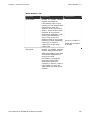
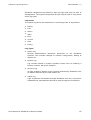
Log Management
Managing Log Servers
When you need to configure the
local and remote log servers
(Server1 – Server 4) or limit the
number of log records that can be
generated per second.
8.2
Configuring Log
Attributes
When you need to control the log
display such as the log levels to be
recorded, select the log levels to
include in email alerts, whether to
log DNS requests etc.
8.3
Exporting Logs
Set up the system to export logs to
the specified FTP server.
8.4
Customizing Log Filter
Criteria and Log
Format
When you need to customize the
filter criteria and format of logs to
be stored via each storage method
(localDB, remote server, email, FTP
export).
8.5
Setting Up Email
Alerts
To set up the system to send email
alerts for specific log entries
including specifying the recipient
addresses
and
time
interval
between the sending of mails etc.
8.6
Viewing Logs
To query and view the admin,
system, security and traffic logs.
8.7
User Manual for SifoWorks D-Series Firewall
35
OD1300UME01-1.3
Chapter 2 Getting started
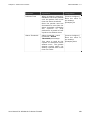
System Settings
Managing
Administrator
Accounts
You should perform this operation if
you want to:
9.2
1. add, edit or delete an existing
admin user account
2. set up attributes such as retry
times, freeze duration for an
account
These operations can only be
performed
by
the
default
administrator account “admin”.
36
Setting up Basic
System Configuration
When you need to set up system
date/time, UI display language,
password recover settings etc.
9.3
Import/Export
Configuration File
When you want to save current
system configurations into a backup
file
or
restore
the
system
configurations from a previously
saved file.
9.4
Upgrade System
Software
When you want to upgrade the
system’s software version.
9.5
Connect to a Network
Management System
When you want to connect the
device to a network management
system to achieve centralized
management.
9.6
Configuring Timeout
Values
When you need to adjust system
timeout configurations to meet your
network requirements or to raise
system performance.
9.7
User Manual for SifoWorks D-Series Firewall
Chapter 2 Getting started
OD1300UME01-1.3
System Maintenance
Monitoring Sessions
and Online Users
To view the list of currently
established sessions and the
authenticated users that are online.
This operation also allows you to
view DHCP lease information.
10.2
Viewing Reports
When you want to enable or disable
report monitoring or view real-time
or history reports of various system
statuses.
10.3
Performing Network
Diagnostics
When you want to execute Ping or
Traceroute commands to check for
network connectivity between
SifoWorks and external networks.
10.4
Restoring System
Settings
When you need to restore the
system’s configurations to factory
default settings, retrieve the
administrative IP or restore the
default administrator password to
the default setting. This operation is
normally performed if you need to
restore the system due to system
failures.
10.5
User Manual for SifoWorks D-Series Firewall
37
OD1300UME01-1.3
Chapter 2 Getting started
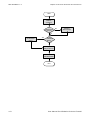
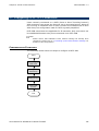
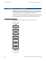
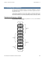
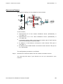
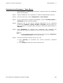
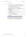
2.5 Device Quick Configuration Guide
The flowchart below shows the recommended configuration procedure to
deploy SifoWorks in your existing network such that the device’s main
functionalities operate properly.
Note:
An application example using this procedure can be found at “11 Device
Deployment Example”.
For details on each configuration task in the following procedure, please
refer to “2.4 Task List” where you can find links to the corresponding
tasks.
38
User Manual for SifoWorks D-Series Firewall
Chapter 2 Getting started
OD1300UME01-1.3
Each operation in this flowchart is briefly explained in the table below.
Operation
Description
Reference
Configuring Basic
Network Parameters
Configure the device’s VPort,
VLAN, IP address and route
settings to connect SifoWorks to
the networks
3.2 Setting up
the Basic
Network
Settings
Configuring NAT
Add SNAT (Source Network
Address Translation) and DNAT
(Destination Network Address
Translation) rules according to
your network requirements.
3.3 Configuring
Network
Address
Translation
If you require a large number of
SNAT rules, you can apply
MapList objects to the rules
instead, reducing the amount of
SNAT rules to be added.
You can also achieve load
balancing
among
multiple
servers by applying server load
balancing objects in DNAT rules.
Setting up Filter
Rules
Set up the filter rules used to
control traffic in the network.
Common types of filter rules
include:
z
IRP (Intelligent Recognized
Protocol)
z
AAA Authentication
Control accesses by users to
be authenticated by local or
remote (RADIUS/LDAP/AD)
authentication servers.
z
Content Filtering
z
QoS
4.2 Managing
Filter Rules
4.4 Managing
Content
Filtering Rules
7.2 Setting Up
QoS Services
In each filter rule, you can
User Manual for SifoWorks D-Series Firewall
z
Specify the incoming and
outgoing interfaces a rule
applies to by selecting Virtual
Port and VLAN.
z
Specify the data packets to
apply a rule using attributes
such as IP address,
authentication user, service or
source MAC address etc.
z
Select whether to “Accept” or
“Drop” data packets matching
the rule.
39
OD1300UME01-1.3
Chapter 2 Getting started
Operation
Configuring VPN
Settings
Description
z
(Optional) Enable the
Intelligent Recognized Protocol
option to control illegal data
flows.
z
If the rule action is “Accept”,
you can apply content filtering
rules to the filter rule to filter
the contents of the data
packets.
z
If the rule action is “Accept”,
you can enable QoS to limit the
maximum and guaranteed
bandwidth available for the
incoming and outgoing
interfaces.
z
If the rule action is “Accept”,
you can specify the maximum
number of concurrent sessions
allowed and limit the number
of connections allowed per host
or network domain.
z
Select a schedule to specify
the time period during which
the rule is effective.
Configure the IPsec VPN, PPTP
VPN and/or L2TP VPN settings to
allow remote users to establish
VPN connections with SifoWorks.
Reference
6.2 Configuring
IPsec VPN
Connections
6.3 Configuring
PPTP VPN
Connections
6.4 Configuring
L2TP VPN
Connections
Setting up IDS
Configure SifoWorks’ own IDS
service or connect the device to
a third-party IDS device to
provide this service.
7.5 Configuring
IDS Services
Note: Detailed explanation of each of the above device functions can be found in
the “Overview” section of the corresponding chapter or in the function’s own
section in this manual.
40
User Manual for SifoWorks D-Series Firewall
3
Chapter
Network Configuration
3
This chapter includes the following sections:
z
Overview
Brief introduction on the various network configuration operations.
z
Setting up the Basic Network Settings
Explains the various network configurations needed to successfully
connect SifoWorks to your network including virtual port, VLAN, IP
address and route configurations.
z
Configuring Network Address Translation
Describes how to add source and/or destination network address
translations.
z
Setting up DHCP Service
Introduces the procedure to set up SifoWorks to act as a DHCP server
or DHCP relay server to provide DHCP services.
z
Configuring PPPoE Connections
Explains, in detail, how to set up SifoWorks to connect to external
networks via PPPoE.
z
Specifying DNS Servers
Explains how to specify IP addresses of DNS servers to equip
SifoWorks with domain name resolution capabilities.
z
Configuring DDNS
Describes the procedure to connect SifoWorks to DDNS servers to
provide DDNS services. This allows users to establish dynamic VPN
connections using the PPPoE access methods.
User Manual for SifoWorks D-Series Firewall
41
OD1300UME01-1.3
Chapter 3 Network Configuration
z
Managing IP-MAC Bindings
Introduces the system’s IP-MAC binding function, preventing IP
addresses from being used by illegal hosts.
z
Managing the ARP Tables
Describes how to manage the static and dynamic ARP tables to
reduce security risks due to ARP/IP spoofing.
Administrators can refer to this chapter when they need to configure
related network settings on the SifoWorks system.
42
User Manual for SifoWorks D-Series Firewall
Chapter 3 Network Configuration
OD1300UME01-1.3
3.1 Overview
Network configuration is a basic module of the SifoWorks system. This
module allows administrators to set up the system to connect to the
network and provide network related services. Administrators must
complete the system’s network configurations according to their actual
network requirements.
To connect SifoWorks to your network correctly, you must first set up the
basic network settings to configure the device’s virtual ports, VLAN, IP
addresses and routes. Please refer to “3.2 Setting up the Basic Network
Settings” for more information.
The remaining sections also describes the procedures to set up SifoWorks
to provide NAT, DHCP services, DNS and DDNS services, IP-MAC binding
mechanism and manage the device’s ARP tables. You can also set up the
device to connect to external networks via PPPoE.
3.2 Setting up the Basic Network Settings
This operation guides you through configuring the device’s virtual ports,
VLANs, IP addresses and routes necessary to connect SifoWorks correctly
in your network.
Virtual Ports
SifoWorks supports up to three virtual ports: Virtual Port 1, Virtual Port 2
and Virtual Port 3. These are not physical ports on the device but are
logical ports used to facilitate the management of the device’s data ports.
Assigning physical data ports to virtual ports allow you to easily manage
the ports when defining filter rules. Filter rules incoming and outgoing
interfaces are defined using virtual ports, thus allowing you to map
multiple physical ports to a single rule. For example, the physical ports
FE0-FE2 are assigned to VPort1 while FE3-FE5 are assigned to VPort2. To
define a filter rule that matches traffic sent from FE0-FE2 to FE3-FE5,
simply select the incoming interface to be VPort1 and the outgoing
interface to be VPort2.
SifoWorks supports 3 virtual ports: Virtual Port 1 (VPort1), Virtual Port 2
(VPort2) and Virtual Port 3 (VPort3). All physical data ports (FE0-FE7)
must be assigned to one of the 3 virtual ports. Each data port can only be
assigned to a single virtual port. Each virtual port can contain multiple
data ports.
User Manual for SifoWorks D-Series Firewall
43
OD1300UME01-1.3
Chapter 3 Network Configuration
VLAN (Virtual Local Area Network)
Virtual local area networks (VLAN) define a logical separation of local
area networks into individual network segments. The main uses of VLANs
include:
z
Separates interfaces
Interfaces assigned to different VLANs can be blocked from
communicating with each other even if the interfaces are on the same
switch. Thus, a single physical switch can be logically viewed as
multiple switches.
z
Enhances network security
VLANs cannot communicate with each other, thus reducing security
risks due to broadcast packets.
z
Facilitate management
VLANs allow administrators to modify the network a user belongs to
via software configuration instead of having to re-arrange the physical
cable connections.
SifoWorks identifies the incoming and outgoing interfaces of a filter rule
using virtual ports and VLANs. Hence, VLANs can be simplified to be used
by SifoWorks to separate network domains of differing security attributes.
A VLAN should be added for each of these domains. Each VLAN is then
assigned to one or more physical SifoWorks data port.
For example, the network domain where the company’s employees are
located should be assigned to 1 VLAN, “LAN”, assigned with the physical
ports FE0 and FE1. The domain where the company’s servers (such as
Web server, mail server etc.) are located is assigned to another VLAN,
“DMZ”, assigned with FE2. A third VLAN, “WAN”, with data port FE3, is
used to identify external networks.
44
User Manual for SifoWorks D-Series Firewall
Chapter 3 Network Configuration
OD1300UME01-1.3
IP, Route and DHCP
According to the actual network environment, you should add IP
addresses to each VLAN and set up SifoWorks to provide DHCP service or
DHCP relay service for each VLAN. You should also add the necessary
static routes and policy routes (if any) for your network.
VLAN IP addresses can be manually added via the system’s UI. You can
also set up SifoWorks to dynamically assign IP address, gateway and DNS
server address information via DHCP. You must enable SifoWorks’ DHCP
Client function for the specific VLAN to dynamically assign IP addresses to.
When enabled:
z
You will be able to view various information including the assigned IP
address, gateway and DNS server etc. Click [Refresh] to view the
status of the connection between the DHCP server and SifoWorks. The
possible status include: “Connecting”, “Connected” and “Failed”. Click
[Release] to release the currently assigned IP address. You can then
manually add another static IP address or select to obtain a new IP
dynamically.
z
When an IP address is dynamically assigned and a static route
specifying the default gateway corresponding to the VLAN has not
been added, SifoWorks automatically adds the gateway address
obtained from the DHCP server as a static route in the “Network >
Route Setting” list.
For
example,
the
dynamic
IP
address
obtained
is
192.168.1.100/255.255.0.0 and the gateway is 192.168.0.1.
SifoWorks will generate a static route using the address 192.168.0.1
as the default gateway for the network segment 0.0.0.0/0.0.0.0.
This operation is not executed if a static route has already been added
prior to the dynamic IP assignment.
z
If the system has been configured to assign DNS information when
assigning dynamic IP addresses and no DNS server address has been
added in the “Network > DNS Setting” interface, the system
automatically sets up SifoWorks DNS setting using the DNS
information obtained.
z
If a VLAN has been configured with the DHCP service (either DHCP
server or DHCP relay server), SifoWorks’ DHCP Client function will not
be effective for this VLAN. Hence, the VLAN cannot be dynamically
assigned with an IP address.
Note:
For details on DNS and DHCP, please refer to “3.6 Specifying DNS
Servers” and “3.4 Setting up DHCP Service” respectively.
You can assign VLAN IP’s manually or dynamically under HA mode. For
details on HA, please refer to “7.4 Activating High Availability”.
Working Mode
SifoWorks supports 3 working modes including transparent mode, route
mode and hybrid mode. When two data ports assigned to different virtual
User Manual for SifoWorks D-Series Firewall
45
OD1300UME01-1.3
Chapter 3 Network Configuration
ports belong to the same VLAN, these two ports are operating in
transparent mode. When two data ports are assigned to different VLANs,
these ports operate in route mode.
z
The system is running in transparent mode if all its data ports are
operating in transparent mode.
z
The system is running in route mode if all its data ports are operating
in route mode.
z
If a portion of the system’s data ports are running in route mode
while another group of ports are running in transparent mode, the
system is operating in hybrid mode.
Access Mode and Trunk Mode
This refers to a VLAN’s working mode. Under access mode, the same data
port can only be assigned to a single VLAN. Under trunk mode, the same
data port can be assigned to multiple VLANs.
Static Routes and Policy Routes
The system supports both static routes and policy routes with policy
routes giving greater flexibility over routing control. The system
prioritizes policy routes.
46
User Manual for SifoWorks D-Series Firewall
Chapter 3 Network Configuration
OD1300UME01-1.3
CONFIGURATION FLOWCHART
The steps to set up the system’s basic network settings are shown in the
flowchart below.
Start
Configuring
Virtual Ports
Configuring
VLANs
Setting up
IP Addresses
Managing
Routes
End
Each step is briefly described in the table below.
Operation
Description
Configuring Virtual Ports
Assigning the data ports to the virtual ports.
Configuring VLANs
Add VLANs and assign data ports to VLANs.
Setting up IP Addresses
Configuring the IP addresses of each VLAN.
This can be static IPs added manually or
dynamic IPs obtained from a DHCP server.
Managing Routes
Adding route information into the system.
User Manual for SifoWorks D-Series Firewall
47
OD1300UME01-1.3
Chapter 3 Network Configuration
APPLICATION EXAMPLE 1 – TRANSPARENT MODE
A company uses private IP addresses within its internal networks,
connecting to external networks via a layer 3 switch and a router. The
external IP address is 210.192.98.220.
For the security of the network and to manage network performance, the
company deploys SifoWorks between the layer 3 switch and router. The
company’s network topology is shown below.
Note:
The IP address “10.1.1.3” in the figure below is used to configure
SifoWorks via a data port. You need not add this IP address if you are
configuring the system via the monitor port only.
SifoWorks is connected to the switch via FE0. SifoWorks is connected to
the router via FE1. The configuration plan is as follows:
48
Parameter
Configuration Value
Virtual Port 1
FE0
Virtual Port 2
FE1
Virtual Port 3
All other ports
VLAN1
FE0, FE1
User Manual for SifoWorks D-Series Firewall
Chapter 3 Network Configuration
OD1300UME01-1.3
Parameter
Configuration Value
IP Address of VLAN1
10.1.1.3/255.255.255.0
Route
-
Note: This example does not require the addition of routes.
The configuration procedure is as follows:
Step 1
Login to SifoWorks via a read/write administrator account.
Step 2
Configuring Virtual Ports
1. From the left menu bar, select “Network > Virtual Port Config”.
2. In this interface, click the [Virtual Port Config] button to display the
“Virtual Port Edit” interface
and
buttons, move port FE0 to Virtual
3. Using the
Port1 and port FE1 to Virtual Port2. Move all other ports to Virtual
Port3.
4. Click [Save] to save the configuration.
User Manual for SifoWorks D-Series Firewall
49
OD1300UME01-1.3
Step 3
Chapter 3 Network Configuration
Configuring VLANs
1. From the left menu bar, select “Network > VLAN Setting” to view
the VLAN list.
2. Click the
icon corresponding to “VLAN1” in the list.
3. The “VLAN Configure” interface will be displayed. Configure as follows:
Virtual Ports: FE0, FE1
MTU: 1500
Status: On
4. Click [Save] to save the configurations.
Step 4
Setting up IP Addresses
1. From the left menu bar, select “Network > IP Config”.
2. From the list of VLANs displayed, click the
“VLAN1”.
icon corresponding to
3. The “Show IP Configure” interface will be displayed. Select the “Static
IP Address” option and click [Add New IP].
4. Enter the IP 10.1.1.3 and Netmask 255.255.255.0.
5. Click [Save] to save the new IP address and return to the “Show IP
Configure” interface.
6. Click [Return] to return to the VLAN IP list.
50
User Manual for SifoWorks D-Series Firewall
Chapter 3 Network Configuration
OD1300UME01-1.3
APPLICATION EXAMPLE 2 – ROUTE MODE
In this example, a company separates its network into 3 domains:
z
LAN
Internal workstation PCs are located in this domain. The subnet
address is 192.168.1.0/255.255.255.0.
z
WAN
The external network (Internet) with IP address 211.192.98.220.
z
DMZ
Internal servers such as web and FTP servers are located in this
domain. The subnet address is 10.1.1.0/255.255.255.0.
For the security of the network and to manage network performance, the
company deploys SifoWorks as the external gateway and connects the 3
network domains to the device. The company’s network topology is
shown below.
Internet
WAN
211.192.98.220
SifoWorks
LAN
192.168.1.1
DMZ
10.1.1.1
LAN Switch
Subnet 1
…
Server Domain
Subnet 2
LAN
Switch
192.168.1.0/24
LAN
Switch
192.168.1.0/24
…
…
LAN
Switch
…
10.1.1.0/24
SifoWorks is connected to LAN via FE0, WAN via FE1 and DMZ via FE2.
The first hop address from the firewall to the Internet is 211.192.98.217.
The configuration plan is shown in the following table.
User Manual for SifoWorks D-Series Firewall
51
OD1300UME01-1.3
Chapter 3 Network Configuration
Parameter
Virtual Port
VLAN
Configuration Value
Virtual Port 1
FE0
Virtual Port 2
FE1
Virtual Port 3
All other ports
LAN
Virtual Port 1: FE0
Virtual Port 2: None
Virtual Port 3: None
WAN
Virtual Port 1: None
Virtual Port 2: FE1
Virtual Port 3: None
DMZ
Virtual Port 1: None
Virtual Port 2: None
Virtual Port 3: FE2
IP Address
LAN
192.168.1.1/255.255.255.0
WAN
211.192.98.220/255.255.255.0
DMZ
10.1.1.1/255.255.255.0
Static Routes
Destination/Netmask: 0.0.0.0/0.0.0.0
Gateway: 211.192.98.217
Outgoing Interface: WAN
The configuration procedure is as follows:
Step 1
Login to SifoWorks using a read/write administrator account.
Step 2
Configuring Virtual Ports
1. From the left menu bar, select “Network > Virtual Port Config”.
2. Click [Virtual Port Config] from the bottom of the virtual port list to
view the “Virtual Port Edit” interface.
and
buttons, move “FE0” to Virtual Port1,
3. Using the
“FE1” to Virtual Port2 and all other ports to Virtual Port3.
4. Click [Save] to save the configuration and return to the Virtual Port
list.
52
User Manual for SifoWorks D-Series Firewall
Chapter 3 Network Configuration
Step 3
OD1300UME01-1.3
Configuring VLANs
1. From the left menu bar, select “Network > VLAN Setting” to
display the list of VLANs.
icon corresponding to “VLAN1” and unselect all data
2. Click the
ports from the VLAN.
3. Return to the VLAN list and click [Add New VLAN] and configure the
following:
Name: LAN
VLAN ID: 2
Select the port “FE0”.
MTU: 1500
Status: Up
4. Click [Save] to save and return to the VLAN list.
5. Repeat steps 2-4 to add two other VLANs for the WAN and DMZ
domains. The resulting list of VLANs is shown in the figure below.
User Manual for SifoWorks D-Series Firewall
53
OD1300UME01-1.3
Step 4
Chapter 3 Network Configuration
Setting up IP Addresses
1. From the left menu bar, select “Network > IP Config”.
2. From the list displayed, click the
icon corresponding to “LAN”. The
system will display the “Show IP Configure” configuration interface.
3. Select “Static IP Address” and Click [Add New IP].
4. In the next interface, configure IP as “192.168.1.1” and netmask
“255.255.255.0”.
5. Click [Save] to save the new IP address and return to the “Show IP
configure” interface.
6. Click [Return] to return to the VLAN IP list.
7. Repeat steps 2-6 and configure “211.192.98.220/255.255.255.0” for
the “WAN” VLAN and “10.1.1.1/255.255.255.0” for the “DMZ” VLAN.
The resulting VLAN IP list is shown below.
Step 5
Managing Routes
1. From the left menu bar, select “Network > Route Setting” to view
the system’s route list.
2. Click [Clear Invalid Route] to remove all unused routes from the
list.
3. Click [Add New Static Route] from the bottom of the list.
4. In the “Add New Static Route” interface that appears, configure the
following:
Destination IP: 0.0.0.0
Destination Mask: 0.0.0.0
Gateway: 211.192.98.217
Dev: WAN
5. Click [Save] to save the route and return to the route list.
54
User Manual for SifoWorks D-Series Firewall
Chapter 3 Network Configuration
OD1300UME01-1.3
APPLICATION EXAMPLE 3 – HYBRID MODE
In this example, the company’s network is separated into two domains:
z
LAN
Internal workstation PCs are located in this domain. The subnet
address is 192.168.1.0/255.255.255.0.
z
WAN
This includes the Internet and a domain where various servers such
as Web and Mail servers are located. The subnet address is
211.192.98.0/255.255.255.0.
For the security of the network and to manage network performance, the
company deploys SifoWorks as the external gateway and connects the
LAN and server domain to the device. The company’s network topology is
shown below.
SifoWorks’ FE0 is connected to the LAN network, FE1 to the Internet and
FE2 to the WAN domain containing the web and mail servers. The first
hop gateway address between the firewall and the Internet is
211.192.98.217. The configuration plan is as follows:
User Manual for SifoWorks D-Series Firewall
55
OD1300UME01-1.3
Chapter 3 Network Configuration
Parameter
Virtual Port
VLAN
Configuration Value
Virtual Port 1
FE0
Virtual Port 2
FE1
Virtual Port 3
All other ports
LAN
Virtual Port 1: FE0
Virtual Port 2: None
Virtual Port 3: None
WAN
Virtual Port 1: None
Virtual Port 2: FE1
Virtual Port 3: FE2
IP Address
LAN
192.168.1.1/255.255.255.0
WAN
211.192.98.220/255.255.255.0
Static Routes
Destination/Netmask: 0.0.0.0/0.0.0.0
Gateway: 211.192.98.217
Outgoing Interface: WAN
The configuration procedure is as follows:
Step 1
Login to SifoWorks via a read/write administrator account.
Step 2
Configuring Virtual Ports
1. From the left menu bar, select “Network > Virtual Port Config”.
2. Click [Virtual Port Config] from the bottom of the virtual port list to
view the “Virtual Port Edit” interface.
and
buttons, move “FE0” to Virtual Port1,
3. Using the
“FE1” to Virtual Port2 and all other ports to Virtual Port3.
4. Click [Save] to save the configuration and return to the Virtual Port
list.
56
User Manual for SifoWorks D-Series Firewall
Chapter 3 Network Configuration
Step 3
OD1300UME01-1.3
Configuring VLANs
1. From the left menu bar, select “Network > VLAN Setting” to
display the list of VLANs.
icon corresponding to “VLAN1” and unselect all data
2. Click the
ports from the VLAN.
3. Return to the VLAN list. Click [Add New VLAN] and configure as
follows:
Name: LAN
VLAN ID: 2
Select the port “FE0”.
MTU: 1500
Status: Up
4. Click [Save] to save and return to the VLAN list.
5. Repeat steps 2-4 to add a “WAN” VLAN. The final VLAN list is shown
in the figure below.
User Manual for SifoWorks D-Series Firewall
57
OD1300UME01-1.3
Step 4
Chapter 3 Network Configuration
Setting up IP Addresses
1. From the left menu bar, select “Network > IP Config”.
2. From the list displayed, click the
icon corresponding to “LAN”. The
system will display the “Show IP Configure” configuration interface.
3. Select “Static IP Address” and click [Add New IP].
4. In the next interface, configure IP as “192.168.1.1” and netmask
“255.255.255.0”.
5. Click [Save] to save the new IP address and return to the “Show IP
configure” interface.
6. Click [Return] to return to the VLAN IP list.
7. Repeat
steps
2-6
and
add
IP/netmask
255.255.255.0” for the “WAN” VLAN.
Step 5
“211.192.98.220/
Managing Routes
1. From the left menu bar, select “Network > Route Setting” to view
the system’s route list.
2. Click [Clear Invalid Route] to remove all unused routes from the
list.
3. Click [Add New Static Route] from the bottom of the list.
4. In the “Add New Static Route” interface that appears, configure the
following:
Destination IP: 0.0.0.0
Destination Mask: 0.0.0.0
Gateway: 211.192.98.217
Dev: WAN
5. Click [Save] to save the route and return to the static route list.
58
User Manual for SifoWorks D-Series Firewall
Chapter 3 Network Configuration
OD1300UME01-1.3
3.3 Configuring Network Address Translation
This section explains how to manage source and destination NAT in
SifoWorks.
Note that your system’s basic network configurations should already be
properly set up. Please refer to “3.2 Setting up the Basic Network
Settings” for information on configuring SifoWorks’ basic network settings.
Source NAT (SNAT)
Performs address translation on the source address of all data packets
matching the rule. Source NAT is mainly used for accesses to the external
networks from internal users.
Destination NAT (DNAT)
Performs address translation on the destination address of all data
packets matching the rule. Destination NAT is mainly used for accesses to
the internal network (such as accesses to an internal web server) from an
external user.
Map List
A maplist object contains a list of multiple address mappings. This object
can be applied on SNAT rules. The system supports up to 10 maplist
objects. Each object can contain a maximum of 1000 address mappings.
As each maplist object can contain multiple address mappings, the use of
these objects can greatly reduce the number of SNAT rules, thus
optimizing system performance. Furthermore, SifoWorks uses the quick
search function to search for matching SNAT rules using maplist objects.
This greatly reduces the search time, further enhancing the performance
of the system.
Hence, we recommend adding SNAT rules that uses maplist objects if
your network requires several source network address translations for
non-continuous IP addresses or port numbers.
User Manual for SifoWorks D-Series Firewall
59
OD1300UME01-1.3
Chapter 3 Network Configuration
Server Load Balancing
SifoWorks is able to balance traffic load on multiple servers via DNAT
rules. You can add up to 10 DNAT rules that apply server load balance
objects. Up to 20 servers can be defined in each object.
The system supports two load balancing mechanisms: round-robin and
server priority. A “Sticky” option is also available in SifoWorks, ensuring
that requests from the same host are processed by the same server.
z
Round-robin
External connection requests will be assigned to the servers in a
round-robin manner. If “Sticky” is enabled, the system will establish a
relationship between source and destination addresses using the hash
algorithm. The connection is then assigned to the next available
server.
z
Server priority
All servers are assigned with a priority weight value. External
connection requests are then distributed to the servers according to
their priority. Servers with larger priority weight will be assigned with
a larger number of requests.
APPLICATION EXAMPLE 1
According to the network topology in “3.2 Setting up the Basic Network
Settings, Application Example 2 – Route Mode” above, you need to add
the following NAT rules:
z
Source NAT from LAN to WAN
The translated source IP is 211.192.98.220, port range is 1025-65535.
z
Destination NAT from WAN to DMZ
The translated destination IP is 10.1.1.2. Destination port number
after translation is 80.
The configuration procedure is as follows:
60
Step 1
Login to SifoWorks using a read/write administrator account.
Step 2
From the left menu bar, select “Firewall > NAT Rule”. The interface
refreshes to display the source NAT rule list (“SNAT” tab) by default.
User Manual for SifoWorks D-Series Firewall
Chapter 3 Network Configuration
Step 3
OD1300UME01-1.3
Add a source NAT rule.
1. From the “SNAT” tab, click [Add New SNAT].
2. In the interface displayed, configure as follows:
Virtual Port From: VPort1
Virtual Port To: VPort2
VLAN From: LAN
VLAN To: WAN
Single IP: 211.192.98.220
Range Port: 1025-65535
3. Click [Save] to save the new SNAT rule and return to the NAT rule
list.
User Manual for SifoWorks D-Series Firewall
61
OD1300UME01-1.3
Step 4
Chapter 3 Network Configuration
Add a destination NAT rule.
1. Back at the “Source NAT” tab interface, click the “Destination NAT”
tab.
2. Click [Add New NAT Rule].
3. In the interface displayed, configure as follows:
Virtual Port From: VPort2
VLAN From: WAN
Address To: 211.192.98.220/255.255.255.255
Service: HTTP
Single IP: 10.1.1.2
Single Port: 80
4. Click [Save] to save the new DNAT rule.
62
User Manual for SifoWorks D-Series Firewall
Chapter 3 Network Configuration
OD1300UME01-1.3
APPLICATION EXAMPLE 2 – MAPLIST
A network administrator needs to add SNAT rules for all LAN to WAN
connections (VPort1 to VPort2) to translate the private IP addresses of all
hosts in the LAN network to two public IP address when accessing the
external network. The internal addresses include:
Original IP address
Translated IP address/Port number
192.168.1.1 – 192.168.1.100
IP: 211.192.98.220
Port: 1025 – 65535
192.168.2.1 – 192.168.2.100
IP: 211.192.98.220
Port: 1025 – 65535
192.168.3.1 – 192.168.3.100
IP: 210.82.98.220
Port: 1025 – 65535
192.168.4.1 – 192.168.4.100
IP: 210.82.98.220
Port: 1025 – 65535
The configuration procedure is as follows:
Step 1
Login to SifoWorks via a read/write administrator account.
Step 2
From the left menu bar, select “Object > MapList”. The list of maplist
objects will be displayed.
User Manual for SifoWorks D-Series Firewall
63
OD1300UME01-1.3
Step 3
Chapter 3 Network Configuration
Add a new maplist object
1. Click [Add New MapList] from the bottom of the maplist object list.
2. Set up the maplist object as follows:
Name: LAN_to_WAN
Original IP: From 192.168.1.1 To 192.168.1.100
Translated IP: From 211.192.98.220 To 211.192.98.220
Translated Port: From 1025 To 65535
3. Click [Save] to save this address mapping.
4. Repeat steps 2 – 3 to add the other 3 address mappings. The final
configuration screen should be similar to the figure below.
5. Click [Return] to return to the maplist object list.
64
User Manual for SifoWorks D-Series Firewall
Chapter 3 Network Configuration
OD1300UME01-1.3
Step 4
From the left menu bar, select “Firewall > NAT Rule”. The “SNAT” tab
displaying the SNAT rule list will be shown.
Step 5
Add a SNAT rule
1. From the SNAT rule list, click [Add New SNAT].
2. Configure the SNAT rule as follows:
Virtual Port From: VPort1
Virtual Port To: VPort2
VLAN From: LAN
VLAN To: WAN
Address From/Specified: All
3. Check the MapList checkbox at the bottom of this interface and
select the maplist object “LAN_to_WAN” from the drop down menu.
The above configuration is illustrated in the figure below.
4. Click [Save] to save the SNAT rule.
User Manual for SifoWorks D-Series Firewall
65
OD1300UME01-1.3
Chapter 3 Network Configuration
APPLICATION EXAMPLE 3 – LOAD BALANCING
The network topology of a company is shown in the figure below. In the
DMZ domain, 5 web servers providing services externally are deployed.
SifoWorks must distribute traffic among these servers according to a
priority weight system. Traffic should be distributed of traffic among Web
Server1 to Web Server5 according to the following percentage:
Server 1 : Server 2 : Server 3 : Server 4 : Server 5
20% : 20% : 25% : 25% : 10%
The “Sticky” option should also be enabled.
Internet
WAN
211.192.98.220
SifoWorks
LAN
192.168.1.1
DMZ
10.1.1.1
Server Domain
Workstation Domain
LAN Switch
…
LAN
Switch
Web Server 1~5
10.1.1.10~10.1.1.14
192.168.1.0/24
The company also requires DNAT to be performed on all accesses from
external sources. External hosts access the HTTP service via the IP
211.192.98.220:80. VPort1, VPort2 and VPort3 correspond to the LAN,
WAN and DMZ domains respectively.
The configuration procedure is as follows:
66
Step 1
Login to SifoWorks via a read/write account.
Step 2
From the left menu bar, select “Object > Server Load Balance”.
User Manual for SifoWorks D-Series Firewall
Chapter 3 Network Configuration
Step 3
OD1300UME01-1.3
Add a new server load balance object
1. From the list of objects displayed, click [Add Server Load Balance].
2. In the “Add Server Load Balance” interface that appears, configure:
Name: Web_Server
Port Translation: From 80 To 80
Load Balance Method: Weight
3. Check the checkbox to enable the Sticky session function.
4. Click “[Add New Server]”. In the Server IP textbox that appears,
enter the IP address of the first web server “10.1.1.10”. In the
adjacent Weight textbox, enter “20”.
5. Repeat (4) to add the remaining 4 web servers. The
configuration interface should be similar to the following figure:
final
6. Click [Save] to save the new server load balance object.
User Manual for SifoWorks D-Series Firewall
67
OD1300UME01-1.3
Chapter 3 Network Configuration
Step 4
From the left menu bar, select “Firewall > NAT Rule”. Click the “DNAT”
tab to view the list of DNAT rules.
Step 5
Add a DNAT rule
1. Click [Add New DNAT].
2. In the configuration interface that displayed, configure as follows:
Virtual Port From: VPort2
VLAN From: WAN
Address From/Predefine: ALL
Address To/Predefine: ALL
3. Check the Server Load Balance checkbox at the bottom of this
interface and select the “Web_Server” object from the drop down
menu.
4. Click [Save] to save the DNAT rule.
68
User Manual for SifoWorks D-Series Firewall
Chapter 3 Network Configuration
OD1300UME01-1.3
3.4 Setting up DHCP Service
You must perform this configuration to set up SifoWorks to provide DHCP
services by either setting up SifoWorks as a DHCP server or using the
system as DHCP relay servers.
DHCP Server
A DHCP server dynamically assigns and manages IP addresses and other
related parameters such as DNS, WINS and gateway to external hosts.
DHCP Relay Server
DHCP relay servers point to a DHCP server located in another subnet,
allowing the server to provide DHCP service to hosts on this subnet.
Note that your system’s basic network configurations should already be
properly set up. Please refer to “3.2 Setting up the Basic Network
Settings” for information on configuring SifoWorks’ basic network settings.
APPLICATION EXAMPLE 1 – DHCP SERVER
As shown in the figure below, SifoWorks provides DHCP services to the
LAN network.
User Manual for SifoWorks D-Series Firewall
69
OD1300UME01-1.3
Chapter 3 Network Configuration
In this network,
z
IP address range available for use by the DHCP service is
192.168.1.10 – 192.168.1.100, and 192.168.1.110 – 192.168.1.200
z
Gateway IP address of the LAN domain is 192.168.1.1/255.255.255.0
z
Default DHCP lease time is 7 days
z
Maximum DHCP lease time is 100 days
z
IP address of the DNS servers are 192.168.1.3 and 192.168.1.4
z
IP address of the WINS servers are 192.168.1.3 and 192.168.1.4
The configuration procedure is as follows:
Step 1
Login to SifoWorks using a read/write administrator account.
Step 2
From the left menu bar, select “Network > DHCP Setting”.
Step 3
icon corresponding to your LAN network’s VLAN from the
Click the
displayed DHCP list.
Step 4
The “Configure DHCP” interface will be displayed. Configure as follows:
DHCP Service Type: DHCP Server
Gateway: 192.168.1.1
Netmask: 255.255.255.0
Default Lease Period: 7 days 0 hours 0 minutes
Max Lease Period: 100 days 0 hours 0 minutes
DNS Server 1: 192.168.1.3
DNS Server 2: 192.168.1.4
WINS Server 1: 192.168.1.3
WINS Server 2: 192.168.1.4
IP Address From: 192.168.1.10
IP Address To: 192.168.1.100
IP Address From: 192.168.1.110
IP Address To: 192.168.1.200
70
User Manual for SifoWorks D-Series Firewall
Chapter 3 Network Configuration
OD1300UME01-1.3
Step 5
Click [Save] to save the configuration and return to the DHCP list.
Step 6
Click the
icon corresponding to the VLAN representing your LAN
network. The DHCP status will be displayed as “Running” in the list as
shown below.
User Manual for SifoWorks D-Series Firewall
71
OD1300UME01-1.3
Chapter 3 Network Configuration
APPLICATION EXAMPLE 2 – DHCP RELAY SERVER
As shown in the network topology below, SifoWorks is set up to provide
DHCP relay services to LAN. IP address of the DHCP server is 10.1.1.3.
The configuration procedure is as follows:
Step 1
Login to SifoWorks using a read/write administrator account.
Step 2
From the left menu bar, select “Network > DHCP Setting”.
Step 3
icon corresponding to the VLAN representing your LAN
Click the
network from the displayed DHCP list.
Step 4
The “Configure DHCP” interface will be displayed. Configure as follows:
DHCP Service Type: DHCP Relay
DHCP Relay Server: 10.1.1.3
Interface: DMZ
72
Step 5
Click [Save] to save the configuration and return to the DHCP list.
Step 6
icon corresponding to the VLAN representing your LAN. The
Click the
DHCP status will be displayed as “Running” in the list as shown below.
User Manual for SifoWorks D-Series Firewall
Chapter 3 Network Configuration
OD1300UME01-1.3
3.5 Configuring PPPoE Connections
To set up SifoWorks such that the device is able to establish connections
with external networks via the PPPoE access method.
PPPoE (Point to Point Protocol over Ethernet) is a widely used Internet
access method. SifoWorks uses the MGT1 port as the interface for PPPoE
connections. Two PPPoE modes are supported including:
z
Common mode
The system processes PPPoE traffic via software. Under this mode,
simply connect the network cable for PPPoE access to the MGT1 port.
As PPPoE traffic is handled by software, this mode ties up a large
amount of system resources. Hence, if PPPoE traffic in your network is
large, we recommend using Fast mode instead.
z
Fast mode
In fast mode, PPPoE traffic is forwarded via hardware by SifoWorks
security chip. Here, you must connect the network cable for PPPoE
accesses to the MGT1 port, then connect a network cable between
MGT0 and FE7.
Up to 50M of traffic is supported under fast mode. As fast mode
forwards PPPoE traffic via hardware, better performance can be
observed under this mode.
Note:
As both MGT0 and MGT1 ports are used in fast mode, administrators
must login to SifoWorks via the FE0 – FE6 data ports.
When configuring filter rules to support PPPoE connections:
z
Under PPPoE common mode, select “PPPoE” in the filter rule’s Virtual
Port From and Virtual Port To parameters. This indicates that the
incoming and outgoing interface is MGT1.
z
Under PPPoE fast mode, select “ADSL_HIGHSPEED” in the filter rule’s
VLAN From and VLAN To parameters to indicate MGT1 as the
incoming and outgoing interface.
When establishing IPsec VPN via PPPoE links:
z
You do not need to specify an outgoing interface under PPPoE
common mode. Simply select “PPPoE” as the Local Interface when
creating the IKE.
z
Under PPPoE fast mode, select “ADSL_HIGHSPEED” as the outgoing
interface.
Note:
For details on configuring filter rules, please refer to “4.2 Managing Filter
Rules”. For details on IPsec VPN configurations, please refer to “6.2
Configuring IPsec VPN Connections”.
User Manual for SifoWorks D-Series Firewall
73
OD1300UME01-1.3
Chapter 3 Network Configuration
CONFIGURATION PROCEDURE – COMMON MODE
Step 1
Connect the network cable for PPPoE access to the MGT1 port.
Step 2
Login to SifoWorks via a read/write administrator account.
Step 3
Select PPPoE mode
1. From the left menu bar, select “Advance > PPPoE Mode”.
2. Select the “Common Mode”.
Note:
Please jump to step 4 if SifoWorks is already working in PPPoE common
mode.
3. Click [Save] to save the settings. SifoWorks will automatically restart.
Please re-login to the system once the system reboots.
Step 4
Establish the PPPoE connection
1. From the left menu bar, select “Network > PPPoE Setting”.
2. In the “Configuration” tab, enter the User Name and Password
used to authenticate SifoWorks when establishing the connection.
Note:
You can also select a schedule/weekly schedule object in the Schedule
drop down menu. The system will attempt to establish / disconnect the
PPPoE connection according to the schedule automatically.
3. Click [Save] to save the settings.
4. Click [Next>] to view the “Connection” tab. Here, you can:
74
−
Click [Start]. The system will begin to dial the connection. Once
connected, you can view various connection information such as IP
address, gateway etc. from the “Monitor” tab.
−
Click [Stop] to disconnect the connection.
User Manual for SifoWorks D-Series Firewall
Chapter 3 Network Configuration
OD1300UME01-1.3
CONFIGURATION PROCEDURE – FAST MODE
Step 1
Connect the network cable for PPPoE access to the MGT1 port.
Step 2
Connect a network cable from MGT0 to FE7.
Step 3
From an available data port (FE0 – FE6), login to SifoWorks using a
read/write administrator account.
Step 4
Select the PPPoE mode
1. From the left menu bar, select “Advance > PPPoE Mode”.
2. Select “Fast Mode”.
Note:
Please jump to step 5 if SifoWorks is already working in PPPoE fast mode.
3. Click [Save] to save the configuration. SifoWorks will automatically
restart. Please re-login to the system once the system reboots.
Step 5
Establish the PPPoE connection
1. From the left menu bar, select “Network > PPPoE Setting”.
2. In the “Configuration” tab, enter the User Name and Password
used to authenticate SifoWorks when establishing the connection.
Note:
You can also select a schedule/weekly schedule object in the Schedule
drop down menu. The system will attempt to establish / disconnect the
PPPoE connection according to the schedule automatically.
3. Click [Save] to save the settings.
4. Click [Next>] to view the “Connection” tab. Here, you can:
−
Click [Start]. The system will begin to dial the connection. Once
connected, you can view various connection information such as IP
address, gateway etc. from the “Monitor” tab.
−
Click [Stop] to disconnect the connection.
User Manual for SifoWorks D-Series Firewall
75
OD1300UME01-1.3
Chapter 3 Network Configuration
3.6 Specifying DNS Servers
To specify the IP addresses of DNS servers to be connected to SifoWorks
so that the system is equipped with domain name resolution capability.
CONFIGURATION PROCEDURE
Step 1
Login to SifoWorks via a read/write administrator account.
Step 2
From the left menu bar, select “Network > DNS Setting”.
Step 3
Enter the IP address of the Primary DNS server.
Step 4
Enter the IP address of the Secondary DNS server.
Step 5
Click [Save] to save the configuration.
3.7 Configuring DDNS
You can connect SifoWorks to a DDNS (Dynamic Domain Name System)
server to provide the DDNS service. This allows users to establish
dynamic VPN connections under the PPPoE access method.
If SifoWorks connects to the Internet via PPPoE, the IP address assigned
to the system changes dynamically each time it establishes a PPPoE
connection. The DDNS service is thus used to resolve static domain
names to dynamic IP addresses.
DDNS service requires cooperation between the server and the client.
Each time the client connects to the Internet and receives a new IP, the
client will inform the DNS server to update the domain name resolution
database. While this client is online, other Internet users accessing this
domain name can thus be pointed to the correct client IP address.
Dynamic VPN connections can be established once DDNS is configured.
For example, in the figure below, SifoWorks A accesses the Internet via a
static IP. SifoWorks B accesses the Internet via PPPoE. Therefore:
76
z
Without DDNS, SifoWorks A will not be able to obtain the IP address
of SifoWorks B. Thus, VPN connections can only be established if
initiated by SifoWorks B.
z
If DDNS is set up, SifoWorks A can obtain the IP address of SifoWorks
B via domain name resolution. Hence, either device will be able to
establish VPN connection with the other.
User Manual for SifoWorks D-Series Firewall
Chapter 3 Network Configuration
OD1300UME01-1.3
CONFIGURATION PROCEDURE
Step 1
Login to SifoWorks using a read/write administrator account.
Step 2
From the left menu bar, select “Network > DDNS Setting”.
Step 3
In the “DDNS Configuration” tab displayed, check to Enable DDNS.
Step 4
From the Service provider drop down menu, select the DDNS service
provider. Enter your registered User Name, Password and the device’s
Domain Name.
DDNS service provider includes: www.3322.org and www.dhs.org.
Step 5
Select the Interface used for DDNS from the drop down menu.
If SifoWorks is using PPPoE fast mode to access the Internet, please
select “ADSL_HIGHSPEED” in the Interface Name parameter.
Step 6
Click [Save] to save the settings.
Step 7
(Optional) You can click the “DDNS Status” tab to view DDNS related
information.
REFERENCE
Related tasks include:
z
3.5 Configuring PPPoE Connections
z
6.2 Configuring IPsec VPN Connections
User Manual for SifoWorks D-Series Firewall
77
OD1300UME01-1.3
Chapter 3 Network Configuration
3.8 Managing IP-MAC Bindings
Binding IP addresses to specific MAC addresses reduces security risks as
users will only be able to access the network via specific host machines.
Some concept explanations are detailed below.
MAC Address
Also known as hardware address or link address, MAC address refers to
the physical address of a network card. MAC address is written into the
network card’s EPROM (Erasable Programmable Read Only Memory) and
acts as the identifier of a network card.
IP Spoofing
This is a complicated network attack that attempts to access protected
hosts illegally. These attack data packets are masqueraded to originate
from trusted addresses, thus tricking firewalls and routers into believing
that the packets are from trusted networks to gain access illegally.
IP addresses of hosts can be easily modified. On the other hand, MAC
addresses are written into the network card itself and are thus difficult to
modify. Hence, binding IP addresses to MAC addresses can help to reduce
IP spoofing attacks.
When SifoWorks receives a data packet, it will first check the packet’s
source IP and MAC addresses against the IP-MAC binding records in its
list. Users can also configure host policies to determine whether to accept
data packets from hosts not included in the ARP tables.
78
User Manual for SifoWorks D-Series Firewall
Chapter 3 Network Configuration
OD1300UME01-1.3
APPLICATION EXAMPLE
In the network topology shown below, we want to bind the IP addresses
of all users in the LAN network.
Internet
WAN
211.192.98.220
SifoWorks
LAN
192.168.1.1
DMZ
10.1.1.1
LAN Switch
Subnet 1
Server Domain
Subnet 2
DHCP Server
10.1.1.3
…
LAN
Switch
192.168.1.0/24
LAN
Switch
192.168.1.0/24
…
…
LAN
Switch
…
10.1.1.0/24
In this network,
z
Range of IP addresses to be binded is 192.168.1.10 – 192.168.1.60
z
Drop all accesses from other IP addresses
z
Enable MAC binding
z
Enable the system to update neighbor’s cache with an update interval
of 10 seconds.
User Manual for SifoWorks D-Series Firewall
79
OD1300UME01-1.3
Chapter 3 Network Configuration
The configuration procedure is as follows:
Step 1
Collect the corresponding MAC addresses for each of the IP addresses in
the range 192.168.1.10 – 192.168.1.60 and record it in a table similar to
the one below.
Note:
SifoWorks automatically adds all static ARP entries into the IP-MAC
binding list and all dynamic ARP entries into the IP-MAC dynamic cache
list. You can select to add IP-MAC pairs in the dynamic cache to the IPMAC binding list.
For more information on ARP, please refer to “3.9 Managing the ARP
Tables”.
IP Address
MAC Address
192.168.1.10
00:14:22:B0:7A:9E
192.168.1.11
00:1C:C3:44:9D:20
…
…
…
…
192.168.1.60
__:__:__:__:__:__
Step 2
Login to SifoWorks via a read/write administrator account.
Step 3
From the left menu bar, select “Network > IP-MAC Binding”.
Step 4
Configure the IP-MAC binding settings
1. From the displayed list (“IP-MAC Binding Setting” tab), click the
icon corresponding to the VLAN representing your LAN network.
2. In the interface displayed, select to “Enable” Source MAC Binding.
“Block” data packets from Undefined Hosts.
3. Click [Save] to save the settings.
80
User Manual for SifoWorks D-Series Firewall
Chapter 3 Network Configuration
Step 5
OD1300UME01-1.3
Set up the static IP-MAC bindings
1. Return to the previous interface and select the “IP MAC Binding Table”
tab to view the current list of IP-MAC bindings.
2. From this list, click [Add New IP-MAC Item].
3. In the configuration interface displayed, enter IP as “192.168.1.10”
and “00:14:22:B0:7A:9B” in the MAC field.
4. Click [Add new IP MAC Binding+] to add a new IP-MAC pair.
5. Repeat step 3 and enter the IP-MAC pair for IP “192.168.1.11”.
6. Repeat steps 4-5 to add all IP-MAC binding pairs according to your IPMAC information table created in step 1 above.
7. Click [OK] to save the configuration.
Step 6
Enable the Update Neighbor’s Cache function
1.
Return to the “Network > IP-MAC Binding” interface and select
the “Update Neighbor’s Cache” tab.
2. Select to Enable the update neighbor’s cache function at an Interval
of “10000” milliseconds.
3. Click [Save] to save the configuration.
User Manual for SifoWorks D-Series Firewall
81
OD1300UME01-1.3
Chapter 3 Network Configuration
3.9 Managing the ARP Tables
This operation helps you to manage your static and dynamic ARP tables,
reducing security risks due to ARP spoofing or IP spoofing. The concepts
relating to this function includes the following.
ARP (Address Resolution Protocol)
Address resolution protocol is used to map an IP address to a MAC
address during the transmission of data packets.
ARP Cache
An ARP cache records IP to MAC mappings in a temporary cache in all
hosts with the TCP/IP protocol installed.
Example: Host A sends data to host B. Before sending a packet, host A
checks its own ARP table for host B’s IP address. If found, host A obtains
host B’s MAC address from the ARP table; otherwise, host A sends a
broadcast packet through the network to obtain host B’s MAC address
and updates it’s own ARP cache accordingly.
ARP cache utilizes an aging mechanism. Any entries that were unused for
a period of time will be removed from the ARP cache.
Dynamic ARP
Dynamic ARP entries are generated during successful address resolutions.
These entries will be automatically removed from the host after a period
of time.
SifoWorks’ dynamic ARP table lists all dynamic ARP entries.
Static ARP
These are ARP entries manually added into the system. Static ARP entries
will not be automatically deleted by the system. Hence, storing static ARP
entries can reduce security risks due to ARP spoof or IP spoof attacks.
You can manually add static ARP into the system from the “Network >
ARP Setting” interface. You can also move selected dynamic ARP entries
to the static ARP table.
82
User Manual for SifoWorks D-Series Firewall
Chapter 3 Network Configuration
OD1300UME01-1.3
CONFIGURATION PROCEDURE
Step 1
Login to SifoWorks via a read/write administrator account.
Step 2
From the left menu bar, select “Network > ARP Setting” to view the
ARP tables.
Step 3
From this interface, you can:
z
Click [Add New Static ARP] to display the “Static ARP Setting”
interface. Enter the IP and MAC addresses and click [OK] to save the
static ARP entry.
z
Click the “Dynamic ARP” tab to view the dynamic ARP table. Select
ARP entries from this table and click [Set to Static] to add the
selected dynamic ARP mappings to the static ARP table.
User Manual for SifoWorks D-Series Firewall
83
4
Chapter
Firewall Rule Management
4
This chapter includes the following sections
z
Overview
Briefly explains the various types of firewall rules including filter rules,
local rules and content filtering rules.
z
Managing Filter Rules
Describes, in detail, how to define filter rules according to your
company’s actual requirements to accurately control the flow of traffic
between the various data ports.
z
Managing Local Rules
Explains how to configure local rules to control accesses to the
SifoWorks system (for configuration and maintenance) via data ports.
z
Managing Content Filtering Rules
Detailed explanation on how to define content filtering rules according
to your company’s requirements, controlling transmitted application
layer packets (including HTTP, FTP and Email packets). This section
also explains the set of special characters that can be used when
defining in the content filtering function.
We recommend reading this chapter if you want to manage the system’s
firewall rules.
User Manual for SifoWorks D-Series Firewall
85
OD1300UME01-1.3
Chapter 4 Firewall Rule Management
4.1 Overview
SifoWorks define 3 types of firewall access control rules.
Filter Rules
These rules determine if packets are allowed to pass through the firewall.
Each filter rule:
z
Identifies the incoming and outgoing interfaces of packets based on
virtual port and VLAN
z
Identifies the data flow according to the packet’s IP address,
authentication user, service or MAC address etc.
z
Specify whether to accept or drop specific traffic using an Action
parameter.
z
Prevents illegal traffic by enabling an optional intelligent recognized
protocol function.
z
Can be configured with content filter rules to filter the contents of the
traffic. This is only configurable if Action is “accept”.
z
Is able to enable QoS to control the guaranteed and maximum
bandwidth allocated to each incoming and outgoing data port. This is
only configurable if Action is “accept”.
z
Is able to limit the number of maximum concurrent connections for
each host or network segment. This is only configurable if Action is
“accept”.
z
Can be configured with a schedule object, specifying when this rule is
effective. For example, a rule can be set up to be effective only
between 1pm – 3pm every Monday.
Local Rules
These rules allow administrators to configure and manage the SifoWorks
system via the network ports. Local rules:
86
z
Identify the incoming interface through virtual port and VLAN
configurations.
z
Identify the data flow based on IP address, service and MAC address.
z
Permits or denies traffic from passing through the firewall through an
Action parameter.
z
Can limit the maximum number of concurrent connections for each
host or network segment. This is only configurable if the rule’s Action
is “accept”.
z
Can be configured with a schedule object, specifying when this rule is
effective. For example, a rule can be set up to be effective only
between 1pm – 3pm every Monday.
User Manual for SifoWorks D-Series Firewall
Chapter 4 Firewall Rule Management
OD1300UME01-1.3
Content Filtering Rules
Content filter rules determine if an application layer data packet (HTTP,
FTP and Email protocols) is allowed to pass through the firewall. Content
filter rules include URL filtering, email filtering, FTP filtering and keyword
filtering.
Content filter rules will only be effective when they are applied on filter
rules.
Before managing any type of firewall rules, please ensure that your
SifoWorks system has been successfully connected to your network by
completing the basic network configuration operation. Please refer to “3.2
Setting up the Basic Network Settings” for details.
4.2 Managing Filter Rules
The SifoWorks system uses a firewall rule list containing a series of
firewall rules. When a packet arrives at the SifoWorks device, the system
matches the packet against this list in a top down fashion. When a
particular rule matches the packet, the system will either:
z
Immediately allow the packet to pass through the firewall if the action
of the matching rule is “accept”;
z
Immediately discards the packet if the action of the matching rule is
“drop”.
Therefore, the positioning of rules in the list affects both the network
operation and system’s performance. You should add and adjust the filter
rule list according to the actual network requirements.
Generally, you are recommended to configure filter rules as follows:
1. Add “accept” filter rules for all external to internal accesses.
2. Add “accept” filter rules for all internal to external accesses.
Please first set up content filtering rules and QoS settings if you intend to
enable these options in any of your filter rules. Please refer to “4.4
Managing Content Filtering Rules” and “7.2 Setting Up QoS Services” for
information on setting up content filtering rules and QoS respectively.
User Manual for SifoWorks D-Series Firewall
87
OD1300UME01-1.3
Chapter 4 Firewall Rule Management
APPLICATION EXAMPLE 1 – INTELLIGENT PROTOCOL RECOGNITION
The network topology used in this example is shown below.
A system administrator wants to set up SifoWorks such that it is able to
enforce the following access control:
z
All external users in the WAN domain can access the web server in
DMZ using the HTTP service
z
All internal LAN users can access the web server in DMZ via the HTTP
service
z
All internal LAN users can access the SMTP server in DMZ via the
SMTP service
z
Enable intelligent recognized protocol to prevent illegal data traffic
z
Log packets that matches any of these filter rules for analysis and
future tracking purposes
The configuration procedure is as follows:
88
Step 1
Login to SifoWorks via a read/write administrator account.
Step 2
From the left menu bar, select “Firewall > Filter Rule” to view the
current list of filter rules.
User Manual for SifoWorks D-Series Firewall
Chapter 4 Firewall Rule Management
Step 3
OD1300UME01-1.3
Add the filter rule to allow WAN users access to the web server.
1. Click [Add New Filter Rule] to display the configuration interface for
adding a new filter rule.
2. Select Action as “Accept”. Click Advanced to display the advanced
options and select to enable Log for this rule.
3. Click [Next>] to display the “Match” tab interface and configure as
follows:
Virtual Port From: VPort2
Virtual Port To: VPort3
VLAN From: WAN
VLAN To: DMZ
Address From/Predefine: All
Address To/Custom(IP/Netmask): 10.1.1.2/255.255.255.255
Service: HTTP
4. Select to enable the Intelligent Recognized Protocol function and
select “http” from the drop down menu. The figure below shows the
above configurations.
5. Click [Save] to save the new filter rule and return to the filter rule
list.
User Manual for SifoWorks D-Series Firewall
89
OD1300UME01-1.3
Step 4
Chapter 4 Firewall Rule Management
Add a filter rule to allow LAN users to access the web server.
1. Click [Add New Filter Rule] to display the configuration interface to
add a new filter rule.
2. Select Action as “Accept”. Click Advanced to display the advanced
options and select to enable Log for this rule.
3. Click [Next>] to view the “Match” tab interface. Configure as follows:
Virtual Port From: VPort1
Virtual Port To: VPort3
VLAN From: LAN
VLAN To: DMZ
Address From/Custom(IP/Netmask): 192.168.1.0/255.255.255.0
Address To/Custom(IP/Netmask): 10.1.1.2/255.255.255.255
Service: HTTP
4. Select to enable the Intelligent Recognized Protocol function and
select “http” from the drop down menu. The figure below shows the
above configurations.
5. Click [Save] to save this filter rule and return to the filter rule list.
90
User Manual for SifoWorks D-Series Firewall
Chapter 4 Firewall Rule Management
Step 5
OD1300UME01-1.3
Add a filter rule to allow LAN users to access the SMTP mail server.
1. Click [Add New Filter Rule] to display the configuration interface to
add a new filter rule.
2. Select Action as “Accept”. Click Advanced to display the advanced
options and select to enable Log for this rule.
3. Click [Next>] to view the “Match” tab interface. Configure as follows:
Virtual Port From: VPort1
Virtual Port To: VPort3
VLAN From: LAN
VLAN To: DMZ
Address From/Custom(IP/Netmask): 192.168.1.0/255.255.255.0
Address To/Custom(IP/Netmask): 10.1.1.3/255.255.255.255
Service: SMTP
4. Select to enable the Intelligent Recognized Protocol function and
select “smtp” from the drop down menu. The figure below shows the
above configurations.
5. Click [Save] to save this filter rule and return to the filter rule list.
User Manual for SifoWorks D-Series Firewall
91
OD1300UME01-1.3
Chapter 4 Firewall Rule Management
APPLICATION EXAMPLE 2 – AAA AUTHENTICATION
The network topology used in this example is shown below.
A system administrator wants to set up SifoWorks such that all users in
the subnet 192.168.1.0/255.255.255.0 must be authenticated before
they can access external networks via HTTP.
The users in this subnet and their authentication information are
tabulated in a table similar to the one below:
User Name
Password
User01
123456
User02
123456
…
…
The configuration procedure is as follows:
Step 1
92
Login to SifoWorks via a read/write administrator account.
User Manual for SifoWorks D-Series Firewall
Chapter 4 Firewall Rule Management
Step 2
OD1300UME01-1.3
Add address object
1. From the left menu bar, select “Object > Address”.
2. Click [Add New Address].
3. In the “Add New Address” interface, configure as follows:
Address Name: ExampleAddress
IP: 192.168.1.0
NetMask: 255.255.255.0
4. Click [Save] to save the address object.
Step 3
Add authentication users
1. From the left menu bar, select “System > Auth User”.
2. Click [Add New Auth User].
3. In the “Add New AuthUser” interface, enter:
User Name: User01
AuthServer: LOCAL
User Attribute: Filterrule
status: Enable
Password: 123456
Confirm Password: 123456
4. Click [Save] to save the authentication user.
5. Repeat steps 2-4 to add the other authentication users.
User Manual for SifoWorks D-Series Firewall
93
OD1300UME01-1.3
Step 4
Chapter 4 Firewall Rule Management
Add authentication user group
1. From the left menu bar, select “System > Auth Group”.
2. Click [Add New Auth User Group].
3. Enter the Auth Group Name “ExampleGroup”. Check the “Filterrule”
Attribute.
4. Select all authentication users added in step 3 above from the
“Available Users” list and click
to assign users to this group.
5. Click [Save] to save the authentication user group.
Step 5
Add authentication address
1. From the left menu bar, select “System > Auth Address”.
2. At the bottom of the list displayed, click [Add New Auth Address].
3. In the “Add New Auth Address” interface, configure as follows:
Name: ExampleAuthAddress
From Address: ExampleAddress
Service: HTTP
Users: ExampleGroup
Note:
Idle Duration refers to the timeout value of users’ access to the Internet
via SifoWorks after authentication. If no Internet access via SifoWorks
was made by the authenticated user for this period of time, the system
will prompt the user to re-authenticate himself.
4. Click [Save] to save the new authentication address.
94
User Manual for SifoWorks D-Series Firewall
Chapter 4 Firewall Rule Management
Step 6
OD1300UME01-1.3
(Optional) Customize authentication interface
1. From the left menu bar, select “System > Auth Server”.
2. Click the “Banner” tab to customize the authentication interface.
3. Here, enter the various messages to be displayed on the user
authentication interface.
4. Click [Save] to save the settings.
Step 7
Add filter rule
1. From the left menu bar, select “Firewall > Filter Rule”.
2. Click [Add New Filter Rule] to view the filter rule addition interface.
3. Select Action as “Accept”. Click Advanced to display the advanced
options and select to enable Log for this rule.
4. Click [Next>] to navigate to the “Match” tab. Here, configure:
Virtual Port From: VPort1
Virtual Port To: VPort2
VLAN From: LAN
VLAN To: WAN
Address From/Authentication: ExampleGroup(Group)
Address To/Predefine: ALL
Service: HTTP
5. Select to enable the Intelligent Recognized Protocol function and
select “http” from the drop down menu. The figure below shows the
above configurations.
6. Click [Save] to save the filter rule.
User Manual for SifoWorks D-Series Firewall
95
OD1300UME01-1.3
Step 8
Chapter 4 Firewall Rule Management
(Optional) Check if the configuration is correct using any of the
authentication users.
Note:
If you can execute this step successfully, you have correctly configured
the system to meet the necessary requirements. Otherwise, please return
to the above steps to check if any errors were made. If the problem
persists, please contact O2Security technical support.
1. Using any PC within the 192.168.1.0/255.255.255.0 subnet and
access the authentication interface.
The authentication interface for authentication users uses the same IP
address as that of SifoWorks management UI. However, the HTTP
protocol is used instead. For example, if SifoWorks management UI
address is “https://192.168.1.1/”, the address of the authentication
interface will be “http://192.168.1.1/”.
Note:
For hosts in subnets that requires authentication before HTTP accesses is
allowed, entering any Internet address into the web browser will
automatically direct the user to the system’s authentication interface.
Upon successful authentication, the user will then be automatically
directed to the entered web address.
2. In the authentication interface, enter the UserName and Password.
3. Click [Auth]. SifoWorks will attempt to authenticate the user. A
success message will be displayed if the authentication is successful.
4. Access other web pages to check that the filter rule is correctly set up.
96
User Manual for SifoWorks D-Series Firewall
Chapter 4 Firewall Rule Management
OD1300UME01-1.3
REFERENCE
Intelligent Protocol Recognition
SifoWorks intelligent recognized protocol function supports the following
types of protocols:
z
HTTP, FTP, SOCKS, SSH, Telnet
z
TFTP, VNC, RTSP, H.323, SIP, IM_HTTP_Proxy
z
SMTP, POP3, IMAP
z
AIM, MSNMessenger, QQ, YahooMessenger, POPO
z
Bittorrent, Edonkey, Mute, Foxy, Kugoo, Xunlei
Additional information on the above protocols:
z
z
Emule and BT
−
SifoWorks
encrypted
encrypted
encrypted
traffic.
is able to block data traffic and apply QoS on nondata packets. However, QoS cannot be applied on
packets. Hence, if the is an excessive amount of
packets, we recommend directly blocking Emule and BT
−
SifoWorks blocks Emule and BT traffic by preventing the client
from obtaining information of seeders from the server. Hence, the
system is unable to block Emule or BT download traffic if seeder
information has already been obtained.
Xunlei
−
Xunlei downloads uses multiple protocols such as FTP, HTTP, BT
and Emule etc. Hence, for HTTP or FTP Xunlei downloads, we
recommend using a combination of FTP and Xunlei protocols to
enforce QoS.
−
For Xunlei downloads using BT and Emule, you should not select
Xunlei when creating the filter rule. Select BT or Emule instead.
User Manual for SifoWorks D-Series Firewall
97
OD1300UME01-1.3
Chapter 4 Firewall Rule Management
AAA Authentication
The AAA module supports up to 1024 local authentication users and 64
authentication groups. Each group can contain up to 512 members.
Group members can be:
z
Local users
z
External authentication servers
z
Users of external authentication servers that are mapped locally
This is used if only a subset of the users on the external
authentication server must be authenticated. To add these users,
navigate to the “System > Auth User > [Add New Auth User]”
interface. Enter the user name and select the corresponding
authentication server. You need not enter password information for
these users.
SifoWorks process filter rules assigned with authentication users in two
phases:
z
Authentication phase
The user enters his authentication information in the authentication
interface. Upon successful authentication, the user will be listed in the
“Online User” list.
z
Authorization phase
The system matches the online user information with filter rules to
assign user authorization. If authentication is required for both source
and destination addresses (that is, “Authentication” is selected for
both Address To and Address From parameters), both users
(source and destination hosts) must be authenticated before the
packet will match the filter rule.
Related Tasks
Operations related to filter rules include:
z
4.4 Managing Content Filtering Rules
z
7.2 Setting Up QoS Services
z
7.6 Upgrade Intelligent Recognized Protocols (IRP)
z
10.2 Monitoring Sessions and Online Users
MAINTENANCE RECOMMENDATIONS
You are recommended to export the current filter rule list ([Export
Rules] button) to a locally saved file before modifying the filter rule list.
98
User Manual for SifoWorks D-Series Firewall
Chapter 4 Firewall Rule Management
OD1300UME01-1.3
4.3 Managing Local Rules
Local rules allow you to control accesses to the SifoWorks system via
data ports. Local rules configuration is not recommended if you do not
require access to the SifoWorks system via data ports.
APPLICATION EXAMPLE
The following network topology is used in this example.
Internet
WAN
211.192.98.220
VPort2
LAN
192.168.1.1
VPort1
SifoWorks
DMZ
10.1.1.1
VPort3
LAN Switch
Subnet 1
Server Domain
Subnet 2
10.1.1.2
…
LAN
Switch
192.168.1.0/24
LAN
Switch
…
…
192.168.1.0/24
LAN
Switch
10.1.1.3
…
10.1.1.0/24
A SifoWorks system administrator wants to be able to manage SifoWorks
via a workstation in the LAN domain. The IP address of this workstation is
192.168.1.10. SifoWorks’ administrative IP is 192.168.1.1.
The configuration procedure is as follows:
Step 1
Login to SifoWorks via a read/write administrator account.
Step 2
From the left menu bar, select “Firewall > Local Rule”.
Step 3
The local rule list will be displayed. From the bottom of this list, click
[Add New Local Rule].
User Manual for SifoWorks D-Series Firewall
99
OD1300UME01-1.3
Chapter 4 Firewall Rule Management
Step 4
Select the rule’s Action as “Accept”.
Step 5
Click [Next>] to view the “Match” tab interface and configure as follows:
Virtual Port From: VPort1
VLAN From: LAN
Address From/Custom(IP/Netmask):192.168.1.10/255.255.255.255
Local Address/Address List: 192.168.1.1
Service: All
Step 6
100
Click [Save] to save the local rule.
User Manual for SifoWorks D-Series Firewall
Chapter 4 Firewall Rule Management
OD1300UME01-1.3
4.4 Managing Content Filtering Rules
Content filtering rules filter contents of application data packets. For
more explanation on content filtering rules, please refer to “4.1 Overview”.
You can define content filtering rules according to your network
requirements. Note, however, that content filter rules will only be
effective when it is selected as part of a packet filter rule. “4.2 Managing
Filter Rules” contains more information on managing filter rules.
CONFIGURATION FLOWCHART
The following flowchart lists the steps to successfully set up content
filtering in the SifoWorks system.
Start
Adding Content
Filtering Objects
Adding Content
Filtering Rules
Applying
Content Filtering
Rules
End
Each step is briefly described in the table below.
Operation
Description
Adding Content Filtering
Objects
Add the objects to be used in the content
filtering rules. This can be URL, mail or
keyword objects.
Adding Content Filtering
Rules
Add the content filtering rules using the
content filtering objects.
Applying Content
Filtering Rules
Apply the content filtering rule within an
“accept” Action filter rule.
For detailed information on managing filter
rules, please refer to “4.2 Managing Filter
Rules”.
User Manual for SifoWorks D-Series Firewall
101
OD1300UME01-1.3
Chapter 4 Firewall Rule Management
APPLICATION EXAMPLE 1 – WEB CONTENT FILTERING
According to the company’s policies, the system administrator wants to
set up SifoWorks to restrict accesses to the following URLs by hosts in
specific subnets.
z
www.sina.com
z
www.sohu.com
z
www.163.com
z
www.china.com
z
www.chinaren.com
z
www.google.cn
The configuration procedure is as follows:
Step 1
Login to SifoWorks via a read/write administrator account.
Step 2
Add a URL content filtering object
1. From the left menu bar, select “Object > Content Filtering Obj”
2. Using a text editor, such as Notepad, create a text file containing a
list of all the above URLs. Save the file as “myURL.txt” as shown in
the figure below.
3. Back in SifoWorks’ URL content filtering object list interface, click
[Add URL Obj].
4. The “Add URL” interface will be displayed. Configure as follows:
Name: myURL
Description: sina, sohu, 163, china, chinaren, google
5. Select File. Click [Browse…] and select the text file containing the
list of URLs created earlier (“myURL.txt”).
102
User Manual for SifoWorks D-Series Firewall
Chapter 4 Firewall Rule Management
OD1300UME01-1.3
6. Click [Save]. The interface will refresh to display a new entry in the
File List.
7. Click [Return] to save this URL object and return to the URL content
filtering object list.
User Manual for SifoWorks D-Series Firewall
103
OD1300UME01-1.3
Step 3
Chapter 4 Firewall Rule Management
Add a web content filtering rule
1. From the left menu bar, select “Firewall > Content Filtering”. The
“Web Filter” tab interface will be displayed.
2. Click [Add Web Filtering] from the bottom of the web filtering rule
list.
3. In the displayed interface, configure:
Name: forbid_popular
Prohibited URL: myURL
Description: forbid accesses to sina, sohu, 163, china, chinaren,
google
4. Click [Save] to save the new rule and return to the web filtering rule
list.
Step 4
Add a new filter rule that applies the “forbid_popular” content filtering
rule as shown in the figure below.
For information on configuring filter rules, please refer to “4.2 Managing
Filter Rules”.
104
User Manual for SifoWorks D-Series Firewall
Chapter 4 Firewall Rule Management
OD1300UME01-1.3
APPLICATION EXAMPLE 2 – MAIL CONTENT FILTERING
Based on the enterprise’s requirements, a system administrator needs to
configure SifoWorks to restrict all mails sent from the mail domains
“@sina.com”, “@sohu.com” and “@163.com”.
The configuration procedure is as follows:
Step 1
Login to SifoWorks via a read/write administrator account.
Step 2
Add a new email content filtering object
1. From the left menu bar, select “Object > Content Filtering Obj”.
2. Click the “Email” tab to view the email content filtering object list.
3. Click [Add Email Obj] from the bottom of the list.
4. In the “Add Email” interface, configure:
Name: myMail
Description: sina, sohu, 163
Email: *@sina.com
5. Click [Save]. This email domain will be added to the Email List.
6. Repeat steps 5-6 to add
(*@sohu.com, *@163.com).
User Manual for SifoWorks D-Series Firewall
the
remaining
two
email
domains
105
OD1300UME01-1.3
Chapter 4 Firewall Rule Management
7. Click [Return] to save this email object and return to the email
content filtering object list.
Step 3
Add a mail content filtering rule
1. From the left menu tree, select “Firewall > Content Filtering”.
2. Click the “Email Filter” tab to display the email content filter rule list.
3. Click [Add Mail Filtering] from the bottom of the list.
4. In the “Add Email Filtering Rule” interface displayed, configure:
Name: forbid_popular
Prohibited Sender: myMail
Description: forbid mail from sina, sohu, 163
5. Click [Save] to save the rule and return to the email filtering rule list.
106
User Manual for SifoWorks D-Series Firewall
Chapter 4 Firewall Rule Management
Step 4
OD1300UME01-1.3
Add a new filter rule that applies the “forbid_popular” content filtering
rule as shown in the figure below.
For information on configuring filter rules, please refer to “4.2 Managing
Filter Rules”.
REFERENCE
Wildcards
SifoWorks supports the use of specific characters as wildcards when
specifying content filtering objects. Wildcards include:
z
“*”
Indicates a string of characters (including the space character) of
arbitrary length.
Examples:
z
−
abc* : Matches any character string beginning with “abc”
−
*abc : matches any character string ending with “abc”
−
*abc* : matches any character string containing “abc”
“?”
Indicates any single character.
Example:
−
abc? : Matches all strings containing 4 characters that begins with
“abc”
User Manual for SifoWorks D-Series Firewall
107
OD1300UME01-1.3
Chapter 4 Firewall Rule Management
Special Character Expressions
SifoWorks also supports a set of special character expressions that allows
administrators to express complicated contents. These expressions
normally made up of a combination of normal and wildcard characters,
matching one more multiple character strings.
The table below lists and explains all special character expressions
supported by SifoWorks.
108
Expression
Explanation
\
Indicates that the character is to be matched as it is
and not as a special character.
^
Matches the starting position of the character string
$
Matches the ending position of the character string
X(x)*
The characters (enclosed in () ) in front of * can
appear 0 or more times. For example, z(o)* will
match “z”, “zo” , “zoo” etc.
X(x)+
The characters (enclosed in () ) in front of + can
appear one or more times. For example, z(o)+ will
match “zo”, “zoo” etc. However, it will not match “z”
X(x)?
The characters (enclosed in () ) in front of ? can
appear 0 or 1 time. For example “do(es)?” will match
“do” or “does”
.
Matches any single character except “\n”. To match
the character set including “\n”, please use “[.\n]”.
(pattern)
Matches “pattern”. All results can be obtained from
the generated Matches set. VBScript uses the
SubMatches set while Visual Basic Scripting Edition
uses the $0…$9 attributes. To match the () brackets,
please use \( and \)
A|B
Matches A or B. For example “z|food” matches either
z or food. “(z|f)ood” will match either “zood” or
“food”
[xyz]
Matches any string containing 1 or more characters
from the character set. For example “[abc]” will
match “plain” since it contains the character “a”.
[a-z]
Matches any string containing 1 or more characters
from this range of characters.
\xN
N is a hexagonal value for the character. For
example, “\x41” will match “A” while “\x041” is
equivalent to “\x04” and “1”. ASCII values of
characters can be used.
User Manual for SifoWorks D-Series Firewall
5
Chapter
Intrusion Detection and Prevention
5
This chapter includes the following:
z
Overview
Briefly introduces SifoWorks’ Intrusion Detection and Prevention (IDP)
module.
z
Configuring and Enabling IDP
Detailed explanation on how to configure and enable IDP.
z
Upgrade IDP Rules
Describes how to upgrade the IDP rule set to the latest version.
Please read this chapter when setting up or modifying the system’s IDP
function.
User Manual for SifoWorks D-Series Firewall
109
OD1300UME01-1.3
Chapter 5 Intrusion Detection and Prevention
5.1 Overview
SifoWorks’ IDP module not only detects intrusion attacks accurately and
effectively, it can also analyze and prevent intrusions according to
network needs.
Warning:
The IDP module ties up a considerable amount of system resources when
activated. Hence, we recommend that you contact O2Security’s technical
support personnel before activating this module.
Enabling this module is not recommended if your network does not
require IDP.
5.2 Configuring and Enabling IDP
This section explains the IDP function and guides you through the steps
to configure and activate IDP on your SifoWorks device.
IDP Work Modes
SifoWorks supports 3 IDP working modes including:
z
Sniffer
This is an attack detection mode. In this mode, the system analyses
data flow to detect intrusions only. The system notifies an
administrator of any detected abnormalities by sending an alert
and/or logging the event.
z
In-line
This is the attack prevention mode. In this mode, the system checks
the data packets for any intrusions. When an abnormality is detected,
the system blocks this data flow to prevent the intrusion.
z
Stop
Disable the IDP module.
IDP Rules
7500 IDP rules are pre-defined by the system, categorized into groups.
You can manually select the rule groups your network requires. You can
also define customize rules for more precise control.
IDP Pre-processors
SifoWorks also supports three pre-processing operations on all traffic
before matching them against the IDP rules to raise system’s
performance and precision. The pre-processors include:
110
User Manual for SifoWorks D-Series Firewall
Chapter 5 Intrusion Detection and Prevention
z
OD1300UME01-1.3
IP Defragmentation
This pre-processor assembles the fragments of a network packet.
z
TCP Stream Reassembly
This pre-processor assembles the payload of multiple packets
belonging to the same TCP connection into one “large” packet before
performing IDP analysis.
z
Port Scan
This pre-processor detects scan attacks on the protected ports. It
automatically sends an alert to the system when such activities are
detected.
Before enabling IDP, please ensure that your SifoWorks system has been
successfully connected to your network by completing the basic network
configuration operation. Please refer to “3.2 Setting up the Basic Network
Settings” for details.
CONFIGURATION FLOWCHART
The configuration steps to configure and activate IDP are illustrated in the
flowchart below.
User Manual for SifoWorks D-Series Firewall
111
OD1300UME01-1.3
Chapter 5 Intrusion Detection and Prevention
Start
Configuring
Network
Variables
Use
Default Rule
Groups?
No
Manage
Rule Groups
Yes
Define
Customized
Rules
Yes
Define
Customized
Rules?
No
Configure the
Pre-processors
Select
IDP Work Mode
End
112
User Manual for SifoWorks D-Series Firewall
Chapter 5 Intrusion Detection and Prevention
OD1300UME01-1.3
Each configuration is briefly introduced in the table below.
Operation
Description
Configuring Network
Variables
Configure the system to differentiate
between internal and external network
addresses.
Manage Rule Groups
Enable entire rule groups or a subset of rules
within a group and modify each rule’s
attributes.
Define Customized
Rules
Add customized IDP rules.
Configure the Preprocessors
Select whether to enable the pre-processors
(IP Defragmentation, TCP Stream
Reassembly, Port Scan) and configure the
corresponding parameters.
Select IDP Work Mode
Specify the IDP working mode.
APPLICATION EXAMPLE
The network topology used in this example is shown below.
Internet
WAN
211.192.98.220
SifoWorks
LAN
192.168.1.1
DMZ
10.1.1.1
LAN Switch
Subnet 1
Server Domain
Subnet 2
DHCP Server
10.1.1.3
…
LAN
Switch
192.168.1.0/24
User Manual for SifoWorks D-Series Firewall
LAN
Switch
192.168.1.0/24
…
…
LAN
Switch
…
10.1.1.0/24
113
OD1300UME01-1.3
Chapter 5 Intrusion Detection and Prevention
After analyzing the network and company’s policies, the administrator
determines that the IDP function must be activated on SifoWorks with the
following configuration:
z
Internal networks: LAN and DMZ domains
z
External network: WAN domain
z
Use system pre-defined rules are to be used
z
No additional customized rules
z
Enable the IP Defragmentation pre-processor with default settings.
The configuration procedure is as follows:
Step 1
Login to SifoWorks using a read/write administrator account.
Step 2
Configure the IDP network variables
1. From the left menu bar, select “IDP > Network Variables”.
2. In the “Home Net” tab, select the User Input radio button to
manually manage the list of internal networks.
3. Click [Add New Home Net].
4. The “Add Home Net” interface will be displayed. Configure as follows:
IP: 192.168.1.0
Netmask Length: 24
5. Click [Save] to save the setting and return to the “Home Net” list.
6. Repeat steps 3 – 5 to add another internal network (DMZ) with
IP/Netmask Length 10.1.1.0/24.
7. Select the “External Net” tab to view the list of external networks.
8. From the top of the list, select the Not Home Net radio button.
114
User Manual for SifoWorks D-Series Firewall
Chapter 5 Intrusion Detection and Prevention
Step 3
OD1300UME01-1.3
Select the IDP rules
1. From the left menu bar, select “IDP > Rule Group Control”.
2. Check the Enable column to select the pre-defined IDP rule groups
that you need to enable.
3. Click [Save] to save the settings.
Step 4
Set up the pre-processor
1. From the left menu bar, select “IDP > Preprocessors” to view the
interface for the “Defragmentation” tab.
2. Select to “Enable” IP Defragmentation.
3. Leave the default settings for all parameters and click [Save] to save
the configuration.
4. Select the “Stream Reassembly” tab and toggle to disable (“Off”) the
TCP stream reassembly pre-processor.
5. Click [Save] to save the settings.
6. Select the “Portscan” tab and toggle to disable (“Off”) the Port scan
pre-processor.
7. Click [Save] to save the settings.
Step 5
Select IDP work mode
1. From the left menu bar, select “IDP > IDP Control”.
2. Enable the IDP state “In-line”.
3. Click [Apply] to save the configuration.
User Manual for SifoWorks D-Series Firewall
115
OD1300UME01-1.3
Chapter 5 Intrusion Detection and Prevention
5.3 Upgrade IDP Rules
Through this function, you can upgrade your system’s IDP pre-defined
rule set to the latest version. The system automatically connects to the
specified O2Security server to obtain the upgrade file.
You should add a notification email address to the system before
performing an IDP upgrade. The system will then able to notify you if the
upgrade failed.
Note:
You can also set up the system to automatically perform an IDP rule
upgrade daily without manual operations from administrators.
CONFIGURATION PROCEDURE
Before performing an IDP rule upgrade, ensure that your SifoWorks
device is able to access external networks.
The configuration procedure is as follows:
Step 1
Login to SifoWorks via a read/write administrator account.
Step 2
(Optional) Specify an email address
1. From the left menu bar, select “IDP > Upgrade Setting”.
2. In this interface, enter the domain name of the SMTP Server used to
send the notification mail, the User Mail Address to send the mail to
and the Password to authenticate SifoWorks with the SMTP server.
3. Click [Save] to save the settings. A success message should be
displayed.
Step 3
Upgrade IDP rules
1. From the left menu column, select “IDP > Rule Upgrade”. The
“Upgrade IDP Rule” interface will be displayed, showing the current
IDP rule version.
2. Click [Upgrade]. An upgrade success message should be displayed
after a few minutes.
3. Click [OK] to return to the “Upgrade IDP Rule” interface. Check to
ensure that the IDP rule version displayed here has been changed.
116
User Manual for SifoWorks D-Series Firewall
6
Chapter
Virtual Private Networks
6
This chapter includes the following:
z
Overview
Briefly introduces SifoWorks high performance VPN engine and
explains basic VPN concepts.
z
Configuring IPsec VPN Connections
Describes how to configure an IPsec VPN connection. Using examples,
this section also introduces how to establish remote access VPN
connections, site to site VPN connections and dynamic VPN
connections based on DDNS.
z
Configuring PPTP VPN Connections
Describes how to configure a PPTP VPN connection.
z
Configuring L2TP VPN Connections
Describes how to configure a L2TP VPN connection.
This chapter is recommended for administrators wanting to configure
SifoWorks’ VPN related settings.
User Manual for SifoWorks D-Series Firewall
117
OD1300UME01-1.3
Chapter 6 Virtual Private Networks
6.1 Overview
SifoWorks provides a high performance VPN engine, supporting IPsec VPN,
PPTP VPN and L2TP VPN. This chapter explains how to set up VPN
connections for each of these 3 types of VPN.
VPN (Virtual Private Network)
This refers to the creation of a temporary and secured connection from a
public network (usually the Internet) to a private network. VPN helps to
extend the company’s internal network boundaries, allowing users on
external networks to access internal resources safely.
The basic functions that a VPN connection should provide include:
z
Data encryption to prevent data, transmitted via the public network,
from being intercepted and leaked.
z
Data and identity authentication to ensure that received data is
complete and legal and to verify users’ identity.
z
Control accesses of different users to different resources.
IPsec (Internet Protocol Security) VPN
IPsec VPN is a commonly used method to establish VPN connections. An
IPsec VPN includes:
z
Transport mode and tunnel mode
Transport mode protects higher layer protocols while tunnel mode
protects the entire IP data packet.
z
Encryption algorithm
SifoWorks supports the DES and 3DES encryption algorithms. DES is
a 64-bit encryption algorithm while 3DES is a 192-bit algorithm. This
also means that 3DES’s encryption strength is three times that of DES.
z
Private key exchange algorithm
SifoWorks includes the DH (Diffe-Hellman key agreement) and RSA
(Rivest, Shamir and Adelman Signatures) private key exchange
algorithms. These algorithms allow the two peers at each end of a
connection to establish a secured shared encryption key via an
unsecured communication tunnel.
118
User Manual for SifoWorks D-Series Firewall
Chapter 6 Virtual Private Networks
z
OD1300UME01-1.3
Verification algorithm
SifoWorks supports the MD5 (Message Digest 5) and SHA-1 (Secure
Hash Algorithm-1) verification algorithms. These algorithms generate
data of a fixed length by processing input data of arbitrary length.
HMAC-MD5
and
HMAC-SHA
are
HMAC
(Hashed
Message
Authentication Codes) strengthened variations of the MD5 and SHA
algorithms. HMAC-MD5 generates an output of length 128-bits while
HMAC-SHA generates output of length 160-bits.
z
IKE (Internet Key Exchange)
Used to verify the peer host at the end of the IPsec connection, and
negotiate IKE SA and IPsec SA security policies.
z
SA (Security Association)
The security association negotiated between two end-points of a
connection determines how to securely transmit data within the
connection via secured services.
An IPsec VPN session goes through 5 main stages:
1. Determines the data packets that must be transmitted via the
secured tunnel;
2. IKE phase one negotiation
The two peers of a connection negotiate an IKE SA to verify the two
peers establishing the IPsec connection. During this phase, a secured
tunnel is also created to be used to negotiate the IPsec SA during IKE
phase two.
3. IKE phase two negotiation
IKE negotiates the IPsec SA parameters and establishes the IPsec SA
between the two connection ends.
4. Data transfer
Establishes the IPsec tunnel for data to be securely transmitted
between the two ends of the connection
5. Terminate the IPsec VPN connection
User Manual for SifoWorks D-Series Firewall
119
OD1300UME01-1.3
Chapter 6 Virtual Private Networks
PPTP (Point to Point Tunneling Protocol) VPN
Implements VPN using the PPTP protocol. PPTP VPN is only suitable for IP
networks. Only 1 tunnel exists between any two end points of a PPTP VPN
connection.
L2TP (Layer 2 Tunneling Protocol) VPN
Implements VPN using the L2TP protocol. L2TP VPN is suitable for various
types of networks including IP, X.25, ATM and frame relay etc. Multiple
tunnels can be established between any two end-points of a L2TP VPN
connection.
Note:
SifoWorks should have already been connected to your network before
configuring VPN. You can refer to “3.2 Setting up the Basic Network
Settings” for details on setting up SifoWorks’ network configurations.
6.2 Configuring IPsec VPN Connections
IPsec VPN is used to achieve two types of connection depending on the
deployment of SifoWorks:
z
Remote access
SifoWorks is deployed only at one end of the VPN connection (such as
the company’s HQ network). This type of VPN connection allows
mobile employees to access the company’s main network remotely.
z
Site-to-site access
Two SifoWorks devices are deployed, one at each end of the VPN
tunnel (such as company HQ and company branch office). Site to site
VPN connections can be used to securely connect branch office
networks to the main network.
Note:
If your network needs to support dynamic VPN connections based on
DDNS, please ensure that you have configured DDNS and PPPoE settings
on SifoWorks. Please refer to “3.7 Configuring DDNS” and “3.5
Configuring PPPoE Connections” for details on DDNS and PPPoE
configurations respectively.
To ensure the reliability of VPN connections, SifoWorks also supports a
VPN backup connection function. The backup connection will be
automatically activated if the main connection is dropped. The figure
below shows an example of a network that applies this function.
Note:
When the main connection is reconnected, the system will switch back to
the main connection from the backup connection. This function is also
supported for connections using the PPPoE access method.
120
User Manual for SifoWorks D-Series Firewall
Chapter 6 Virtual Private Networks
OD1300UME01-1.3
Note that you must add two IKE objects to enable the VPN backup
connection function on SifoWorks. Enable this function from the “Add New
VPN Connection” interface as shown below.
User Manual for SifoWorks D-Series Firewall
121
OD1300UME01-1.3
Chapter 6 Virtual Private Networks
CONFIGURATION FLOWCHART
The flowchart below shows the steps to implement IPsec VPN using
SifoWorks.
Start
Configuring
Basic Network
Settings
Enable VPN
Select Outgoing
Interface
Adding IKE
Use
Certificates?
No
Yes
Adding
Certificates
Adding
Address Objects
Adding VPN
Connections
End
122
User Manual for SifoWorks D-Series Firewall
Chapter 6 Virtual Private Networks
OD1300UME01-1.3
Each of the steps above is briefly introduced in the table below.
Operation
Description
Configuring Basic
Network Settings
Refers to the configuration of virtual ports,
VLANs, IP addresses and routes necessary to
connect SifoWorks to the network. Note that
you should assign the outgoing ports for VPN
connections to virtual Port 2.
For detailed information on how to configure
these settings, please refer to “3.2 Setting
up the Basic Network Settings”.
Enable VPN
N.A.
Select Outgoing
Interface
Select the VLAN (assigned with data ports in
Virtual Port 2) to use these data ports as the
outgoing interface for VPN connections.
Adding Certificates
Add the root CA, local CA and remote CA if
needed for IKE authentication.
Please skip this step if you are using the
shared private key method for IKE
authentication.
Adding IKE
Add the IKE (Internet Key Exchange) used to
establish VPN connections.
Adding Address Objects
Add address objects representing the two
end-points of a VPN connection.
Adding VPN Connections
N.A.
APPLICATION EXAMPLE 1 – REMOTE ACCESS
A system administrator wants to set up SifoWorks to implement IPsec
VPN in the network shown below so as to provide secured remote
accesses to internal resources by mobile employees.
User Manual for SifoWorks D-Series Firewall
123
OD1300UME01-1.3
Chapter 6 Virtual Private Networks
In this network,
z
First hop gateway IP from firewall to Internet is 211.192.98.217
z
Pre-shared private key “123456” is used for authentication
z
IKE phase 1 algorithm is “3des-md5-modp1536”
z
IKE phase 2 algorithm is “esp-3des-md5”
The configuration procedure is as follows:
Step 1
Login to SifoWorks via a read/write administrator account.
Step 2
Enable VPN
1. From the left menu bar, select “VPN > IPSec Setting”.
2. Toggle the VPN module “ON”.
3. Click [Save] to confirm the setting.
Step 3
Select the outgoing interface
1. From the “VPN > IPSec Setting” interface, click the “IPSec
Interface IP” tab.
2. Select the VLAN “WAN” as the outgoing interface.
3. Click [Save] to save the configuration.
124
User Manual for SifoWorks D-Series Firewall
Chapter 6 Virtual Private Networks
Step 4
OD1300UME01-1.3
Add IKE
1. From the left menu bar, select “VPN > IKE”.
2. From the bottom of the IKE list displayed, click [Add New IKE].
3. The “Add New IKE” interface will be displayed. Configure as follows
IKE Name: RemoteIKE
Remote Gateway: Dynamic
NextHop: 211.192.98.217
4. Click [Next>] to display the “Phase One Method” tab. Configure as
follows:
Algorithm: 3des-md5-modp1536
Exchange: main mode
5. Click [Next>] to view the “Authenticate Method” tab. Select PSK and
enter “123456” as the Preshare Key. Re-enter this key in the
Retype textbox to confirm.
6. Click [Next>] to display the “Phase Two Proposal” tab. Enable Using
ESP and select the “esp-3des-md5” ESP Algorithm. Also select the
Using PFS option.
7. Click [Next>] to view the “Advanced Setting” tab. Keep the default
configuration for all parameters in this tab and click [Save] to save
this IKE record.
User Manual for SifoWorks D-Series Firewall
125
OD1300UME01-1.3
Step 5
Chapter 6 Virtual Private Networks
Add address objects
1. From the left menu bar, select “Object > Address” to display the
list of address objects.
2. Click [Add New Address] and configure as follows:
Name: Local
IP: 192.168.1.0
Netmask: 255.255.255.0
3. Click [Save] to add the new address object.
Step 6
Add VPN connection
1. From the left menu bar, select “VPN > VPN Connection” to view
the list of VPN connections.
2. Click [Add New VPN].
3. In the “Add New VPN Connection” interface, configure as follows:
Connection Name: RemoteConnect
Local Subnet: Local
Remote Subnet: roadwarrior
Using Tunnel/Using IKE: RemoteIKE
State: Start
Note:
If the remote subnet of this VPN connection is dynamic (such as mobile
client-end), select the address object “roadwarrior” for the Remote
Subnet field. In this situation, VPN connections can only be initiated from
the remote clients.
126
User Manual for SifoWorks D-Series Firewall
Chapter 6 Virtual Private Networks
OD1300UME01-1.3
4. Click [Save] to add this VPN connection to the list.
APPLICATION EXAMPLE 2 – SITE TO SITE ACCESS
Two SifoWorks devices are deployed by the company, one in its HQ office
network and another in its branch office network. To provide for secured
accesses between the branch and HQ networks, the system
administrators at each network must set up their respective SifoWorks
device such that both devices are connected via a site-to-site VPN
connection.
The network topology is shown below.
In the HQ network, SifoWorksA is deployed. The first hop gateway
address from SifoWorksA to the Internet is 211.192.98.217.
SifoWorksB is deployed at the branch network and the first hop gateway
address connecting SifoWorksB to the Internet is 202.112.11.1.
The site-to-site VPN connection uses pre-shared key authentication. The
pre-shared key is “12345678”. IKE phase one algorithm is “3des-md5modp1536” and the phase two algorithm is “esp-3des-md5”.
The configuration procedure is as follows:
User Manual for SifoWorks D-Series Firewall
127
OD1300UME01-1.3
Chapter 6 Virtual Private Networks
SifoWorksA – HQ Network
Step 1
Login to SifoWorksA via a read/write administrator account.
Step 2
Activate VPN on SifoWorksA
1. From the left menu bar, select “VPN > IPSec Setting”.
2. Toggle the VPN module “On”.
3. Click [Save] to confirm the setting.
Step 3
Select the outgoing interface for SifoWorksA
1. From the “VPN > IPSec Setting” interface, click the “IPSec
Interface IP” tab.
2. Select the VLAN “WAN” as the outgoing interface.
3. Click [Save] to save the configuration.
Step 4
Adding IKE for SifoWorksA
1. From the left menu bar, select “VPN > IKE”.
2. From the bottom of the IKE list displayed, click [Add New IKE].
3. The “Add New IKE” interface will be displayed. Configure as follows:
IKE Name: HQIKE
Remote Gateway: Static
Gateway IP: 202.112.11.222
NextHop: 211.192.98.217
4. Click [Next>] to display the “Phase One Method” tab. Configure
according to the following:
Algorithm: 3des-md5-modp1536
Exchange: main mode
128
User Manual for SifoWorks D-Series Firewall
Chapter 6 Virtual Private Networks
OD1300UME01-1.3
5. Click [Next>] to view the “Authenticate Method” tab. Select PSK and
enter “12345678” as the Preshare Key. Re-enter this key in the
Retype textbox to confirm.
6. Click [Next>] to display the “Phase Two Proposal” tab. Enable Using
ESP and select the “esp-3des-md5” ESP Algorithm. Also select the
Using PFS option.
7. Click [Next>] to view the “Advanced Setting” tab. Keep the default
configuration for all parameters in this tab and click [Save] to save
this IKE record.
Step 5
Add address objects on SifoWorksA
1. From the left menu bar, select “Object > Address” to display the
list of address objects.
2. Click [Add New Address] and configure as follows:
Name: Local
IP: 192.168.1.0
Netmask: 255.255.255.0
3. Click [Save] to add the new address object.
4. Back at the address object list, click [Add New Address] to add
another address object with the following configuration:
Name: Remote
IP: 192.168.2.0
Netmask: 255.255.255.0
5. Click [Save] to save this address object.
User Manual for SifoWorks D-Series Firewall
129
OD1300UME01-1.3
Step 6
Chapter 6 Virtual Private Networks
Add VPN connection on SifoWorksA
1. From the left menu bar, select “VPN > VPN Connection” to view
the list of VPN connections.
2. Click [Add New VPN].
3. In the “Add New VPN Connection” interface, configure as follows:
Connection Name: HQConnect
Local Subnet: Local
Remote Subnet: Remote
Using Tunnel/Using IKE: HQIKE
State: Start
4. Click [Save] to add this VPN connection to the list.
SifoWorksB – Branch Network
Step 7
Login to SifoWorksB via a read/write administrator account.
Step 8
Activate VPN on SifoWorksB
1. From the left menu bar, select “VPN > IPSec Setting”.
2. Toggle the VPN module “On”.
3. Click [Save] to confirm the setting.
130
User Manual for SifoWorks D-Series Firewall
Chapter 6 Virtual Private Networks
Step 9
OD1300UME01-1.3
Select the outgoing interface for SifoWorksB
1. From the “VPN > IPSec Setting” interface, click the “IPSec
Interface IP” tab.
2. Select the VLAN “WAN” as the outgoing interface.
3. Click [Save] to save the configuration.
Step 10
Add IKE for SifoWorksB
1. From the left menu bar, select “VPN > IKE”.
2. From the bottom of the IKE list displayed, click [Add New IKE].
3. The “Add New IKE” interface will be displayed. Configure as follows:
IKE Name: BranchIKE
Remote Gateway: Static
Gateway IP: 211.192.98.220
NextHop: 202.112.11.1
4. Click [Next>] to display
configuration is as follows:
the “Phase One
Method”
tab.
The
Algorithm: 3des-md5-modp1536
Exchange: main mode
5. Click [Next>] to view the “Authenticate Method” tab. Select PSK and
enter “12345678” as the Preshare Key. Re-enter this key in the
Retype textbox to confirm.
User Manual for SifoWorks D-Series Firewall
131
OD1300UME01-1.3
Chapter 6 Virtual Private Networks
6. Click [Next>] to display the “Phase Two Proposal” tab. Enable Using
ESP and select the “esp-3des-md5” ESP Algorithm. Also select the
Using PFS option.
7. Click [Next>] to view the “Advanced Setting” tab. Keep the default
configuration for all parameters in this tab and click [Save] to save
this IKE record.
Step 11
Add address objects on SifoWorksB
1. From the left menu bar, select “Object > Address” to display the
list of address objects.
2. Click [Add New Address] and configure as follows:
Name: Local
IP: 192.168.2.0
Netmask: 255.255.255.0
3. Click [Save] to add the new address object.
4. Back at the address object list, click [Add New Address] to add
another address object with the following configuration:
Name: Remote
IP: 192.168.1.0
Netmask: 255.255.255.0
5. Click [Save] to save this address object.
132
User Manual for SifoWorks D-Series Firewall
Chapter 6 Virtual Private Networks
Step 12
OD1300UME01-1.3
Add VPN connection on SifoWorksB
1. From the left menu bar, select “VPN > VPN Connection” to view
the list of VPN connections.
2. Click [Add New VPN].
3. In the “Add New VPN Connection” interface, configure as follows:
Connection Name: BranchConnect
Local Subnet: Local
Remote Subnet: Remote
Using Tunnel/Using IKE: BranchIKE
State: Start
4. Click [Save] to add this VPN connection to the list.
User Manual for SifoWorks D-Series Firewall
133
OD1300UME01-1.3
Chapter 6 Virtual Private Networks
APPLICATION EXAMPLE 3 – DYNAMIC VPN BASED ON DDNS
The network topology used in this example is shown below.
To ensure that communications between the network at the HQ office and
that at the branch office is secure, the system administrators of each
network needs to set up their SifoWorks to establish site-to-site VPN
connections with the other network.
At the HQ office, the first hop gateway address between SifoWorks and
the Internet is 211.192.98.217.
At the branch office, SifoWorks is connected to the Internet using PPPoE
fast mode. The network’s domain name registered with the DDNS service
is
www.example.com.
VPN
connections
uses
pre-shared
key
authentication with the pre-shared key “12345678”. IKE phase one
algorithm is “3des-md5-modp1536” and the phase two algorithm is “esp3des-md5”.
The configuration procedure is as follows:
SifoWorksA – HQ Network
Step 1
Login to SifoWorks via a read/write administrator account.
Step 2
Enable VPN on SifoWorksA
1. From the left menu bar, select “VPN > IPSec Setting”.
2. Toggle the VPN module “On”.
3. Click [Save] to confirm the setting.
Step 3
Select the outgoing interface for SifoWorksA
1. From the “VPN > IPSec Setting” interface, click the “IPSec
Interface IP” tab.
2. Select the VLAN “WAN” as the outgoing interface.
3. Click [Save] to save the configuration.
134
User Manual for SifoWorks D-Series Firewall
Chapter 6 Virtual Private Networks
Step 4
OD1300UME01-1.3
Adding IKE for SifoWorksA
1. From the left menu bar, select “VPN > IKE”.
2. From the bottom of the IKE list displayed, click [Add New IKE].
3. The “Add New IKE” interface will be displayed. Configure as follows:
IKE Name: HQIKE
Remote Gateway: Dynamic DNS
Domain: www.example.com
NextHop: 211.192.98.217
4. Click [Next>] to display the “Phase One Method” tab. Configure
according to the following:
Algorithm: 3des-md5-modp1536
Exchange: main mode
5. Click [Next>] to view the “Authenticate Method” tab. Select PSK and
enter “12345678” as the Preshare Key. Re-enter this key in the
Retype textbox to confirm.
6. Click [Next>] to display the “Phase Two Proposal” tab. Enable Using
ESP and select the “esp-3des-md5” ESP Algorithm. Also select the
Using PFS option.
7. Click [Next>] to view the “Advanced Setting” tab. Keep the default
configuration for all parameters in this tab and click [Save] to save
this IKE record.
User Manual for SifoWorks D-Series Firewall
135
OD1300UME01-1.3
Step 5
Chapter 6 Virtual Private Networks
Add address objects on SifoWorksA
1. From the left menu bar, select “Object > Address” to display the
list of address objects.
2. Click [Add New Address] and configure as follows:
Name: Local
IP: 192.168.1.0
Netmask: 255.255.255.0
3. Click [Save] to add the new address object.
4. Back at the address object list, click [Add New Address] to add
another address object with the following configuration:
Name: Remote
IP: 192.168.2.0
Netmask: 255.255.255.0
5. Click [Save] to save this address object.
Step 6
Add VPN connection on SifoWorksA
1. From the left menu bar, select “VPN > VPN Connection” to view
the list of VPN connections.
2. Click [Add New VPN].
3. In the “Add New VPN Connection” interface, configure as follows:
Connection Name: HQConnect
Local Subnet: Local
Remote Subnet: Remote
Using Tunnel/Using IKE: HQIKE
State: Start
136
User Manual for SifoWorks D-Series Firewall
Chapter 6 Virtual Private Networks
OD1300UME01-1.3
4. Click [Save] to add this VPN connection to the list.
SifoWorksB – Branch Network
Step 7
Login to SifoWorksB via a read/write administrator account.
Step 8
Activate VPN on SifoWorksB
1. From the left menu bar, select “VPN > IPSec Setting”.
2. Toggle the VPN module “On”.
3. Click [Save] to confirm the setting.
Step 9
Select the outgoing interface for SifoWorksB
1. From the “VPN > IPSec Setting” interface, click the “IPSec
Interface IP” tab.
2. Select the VLAN “ADSL_HIGHSPEED” as the outgoing interface.
3. Click [Save] to save the configurations.
User Manual for SifoWorks D-Series Firewall
137
OD1300UME01-1.3
Step 10
Chapter 6 Virtual Private Networks
Add IKE for SifoWorksB
1. From the left menu bar, select “VPN > IKE”.
2. From the bottom of the IKE list displayed, click [Add New IKE].
3. The “Add New IKE” interface will be displayed. Configure as follows:
IKE Name: BranchIKE
Remote Gateway: Static
Gateway IP: 211.192.98.220
4. Click [Next>] to display
configuration is as follows:
the “Phase One
Method”
tab.
The
Algorithm: 3des-md5-modp1536
Exchange: main mode
5. Click [Next>] to view the “Authenticate Method” tab. Select PSK and
enter “12345678” as the Preshare Key. Re-enter this key in the
Retype textbox to confirm.
6. Click [Next>] to display the “Phase Two Proposal” tab. Enable Using
ESP and select the “esp-3des-md5” ESP Algorithm. Also select the
Using PFS option.
7. Click [Next>] to view the “Advanced Setting” tab. Keep the default
configuration for all parameters in this tab and click [Save] to save
this IKE record.
138
User Manual for SifoWorks D-Series Firewall
Chapter 6 Virtual Private Networks
Step 11
OD1300UME01-1.3
Add address objects on SifoWorksB
1. From the left menu bar, select “Object > Address” to display the
list of address objects.
2. Click [Add New Address] and configure as follows:
Name: Local
IP: 192.168.2.0
Netmask: 255.255.255.0
3. Click [Save] to add the new address object.
4. Back at the address object list, click [Add New Address] to add
another address object with the following configuration:
Name: Remote
IP: 192.168.1.0
Netmask: 255.255.255.0
5. Click [Save] to save this address object.
Step 12
Add VPN connection on SifoWorksB
1. From the left menu bar, select “VPN > VPN Connection” to view
the list of VPN connections.
2. Click [Add New VPN].
3. In the “Add New VPN Connection” interface, configure as follows:
Connection Name: BranchConnect
Local Subnet: Local
Remote Subnet: Remote
Using Tunnel/Using IKE: BranchIKE
State: Start
User Manual for SifoWorks D-Series Firewall
139
OD1300UME01-1.3
Chapter 6 Virtual Private Networks
4. Click [Save] to add this VPN connection to the list.
REFERENCE
Operations related to IPsec VPN connections include:
140
z
3.2 Setting up the Basic Network Settings
z
3.5 Configuring PPPoE Connections
z
3.7 Configuring DDNS
User Manual for SifoWorks D-Series Firewall
Chapter 6 Virtual Private Networks
OD1300UME01-1.3
6.3 Configuring PPTP VPN Connections
Users remotely connected on a PPTP (Point to Point Tunneling Protocol)
VPN connection can access the Internet via an encrypted tunnel. Since all
PCs running on Windows 2000 or later versions are installed with a PPTP
VPN client, the configuration task for PPTP is greatly simplified.
PPTP VPN connections are applicable for IP networks. Only one tunnel can
be established between two peers connected via a PPTP VPN.
Note:
Please ensure that SifoWorks’ basic network setting has already been
configured. Please refer to “3.2 Setting up the Basic Network Settings” for
details on this configuration.
CONFIGURATION FLOWCHART
The flowchart below shows the steps to configure a PPTP VPN.
Start
Adding
VPN Users
Adding VPN
User Group
Adding IP Pool
Configuring
PPTP VPN
Access
End
User Manual for SifoWorks D-Series Firewall
141
OD1300UME01-1.3
Chapter 6 Virtual Private Networks
This table briefly introduces each of the configuration steps.
Operation
Description
Adding VPN Users
To add PPTP VPN connection users.
Adding VPN User
Groups
To manage PPTP VPN connection users using
group objects for configuration convenience.
Adding IP Pool
To define a pool of IP addresses for PPTP VPN
connections. This prevents accesses to the
network via PPTP VPN from illegal users
Configuring PPTP VPN
Access
N.A.
CONFIGURATION PROCEDURE
Step 1
Add VPN users
1. From the left menu bar, select “System > Auth User” to view the
list of authentication users.
2. Click [Add New Auth User] from the bottom of this list.
3. In the displayed interface, enter the user’s User Name and
Password.
4. Select “PPTP” for the User Attribute parameter.
5. Click [Save] to save the new authentication user.
6. Repeat steps 2-5 to add other authentication users.
Step 2
Add VPN user groups
1. From the left menu bar, select “System > Auth Group”.
2. At the bottom of this list, click [Add New Auth User Group].
3. Here, enter the authentication group Name. Select “PPTP” for
Attribute. In Auth Group, select the users from the “Available
Users” list and click the
button to add them to this group.
4. Click [Save] to save the authentication group.
Step 3
Add IP pool
1. From the left menu bar, select “Object > IP Pool”.
2. Click [Add New IP Pool] from the bottom of the IP Pool Object list.
3. Enter the Name of the IP pool object and specify the IP range in the
IP From and IP To textboxes.
4. Click [Save] to save the new IP pool object.
142
User Manual for SifoWorks D-Series Firewall
Chapter 6 Virtual Private Networks
Step 4
OD1300UME01-1.3
Configure PPTP VPN access
1. From the left menu bar, select “VPN > PPTP”.
2. In the “PPTP VPN Access” tab, configure as follows:
State: Start
Encryption: 128bit or 40bit
IP Pool: Select the IP pool object added in the previous step.
User: Select the user group object added in step 2 or the user object
added in step 1.
An example of the above configuration is shown in the figure below.
3. Click [Next>] to display the “Remote Client Parameters” tab.
4. (Optional) Enter the addresses of DNS and WINS servers to be used
by the remote PPTP VPN users.
5. Click [Save] to save the PPTP VPN configurations.
User Manual for SifoWorks D-Series Firewall
143
OD1300UME01-1.3
Chapter 6 Virtual Private Networks
6.4 Configuring L2TP VPN Connections
Remote access users connected via a VPN connection over L2TP (Layer 2
Tunneling Protocol) accesses the internal network via an encrypted tunnel.
Configuration for L2TP VPN is simplified as all PCs running windows 2000
or later operating systems are installed with the L2TP client.
L2TP VPN connections can be established in various types of networks
including IP, X.25, ATM and frame relay networks etc. Multiple tunnels
can be established between two end points of a L2TP VPN connection.
CONFIGURATION FLOWCHART
The flowchart below shows the steps to configure a L2TP VPN.
Start
Activating VPN
Adding
VPN Users
Adding VPN
User Group
Adding IP Pool
Adding IKE
Adding VPN
Connections
Configuring
L2TP VPN
Access
End
144
User Manual for SifoWorks D-Series Firewall
Chapter 6 Virtual Private Networks
OD1300UME01-1.3
This table briefly introduces each of the configuration steps.
Operation
Description
Activating VPN
N.A.
Adding VPN Users
To add L2TP VPN connection users.
Adding VPN User Groups
To manage L2TP VPN connection users
using group objects for configuration
convenience.
Adding IP Pool
To define a pool of IP addresses for L2TP
VPN connections. This prevents accesses to
the network via L2TP VPN from illegal
users
Adding IKE
To add the IKE used to establish L2TP VPN
connections.
Please refer to “6.2 Configuring IPsec VPN
Connections” for details on IKE
configuration.
Adding VPN Connection
To add a VPN connection that uses L2TP.
Please refer to “6.2 Configuring IPsec VPN
Connections” for information on how to add
VPN connections
Configuring L2TP VPN
Access
N.A.
CONFIGURATION PROCEDURE
Step 1
Activate VPN
1. From the left menu bar, select “VPN > IPSec Setting”.
2. In the “IPSec Switch” tab, toggle the VPN module “On”.
3. Click [Save] to save the setting.
Step 2
Add VPN users
1. From the left menu bar, select “System > Auth User” to view the
list of authentication users.
2. Click [Add New Auth User] from the bottom of this list.
3. In the displayed interface, enter the user’s User Name and
Password.
4. Select “L2TP” for the User Attribute parameter.
5. Click [Save] to save the new authentication user.
6. Repeat steps 2-5 to add other authentication users.
User Manual for SifoWorks D-Series Firewall
145
OD1300UME01-1.3
Step 3
Chapter 6 Virtual Private Networks
Add VPN user groups
1. From the left menu bar, select “System > Auth Group”.
2. At the bottom of this list, click [Add New Auth User Group].
3. Here, enter the authentication group Name. Select “L2TP” for
Attribute. In Auth Group, select users from the “Available Users”
list and click the
button to assign them to this group.
4. Click [Save] to save the authentication group.
Step 4
Add IP pool
1. From the left menu bar, select “Object > IP Pool”.
2. Click [Add New IP Pool] from the bottom of the IP Pool Object list.
3. Enter the Name of the IP pool object and specify the IP range in the
IP From and IP To textboxes.
4. Click [Save] to save the new IP pool object.
Step 5
Add IKE
Add the IKE needed to establish L2TP VPN connections. Please disable the
Strict Algorithm Match option when adding IKE. You can refer to “6.2
Configuring IPsec VPN Connections” for more information on IKE
configuration.
Step 6
Add VPN connection
To add a VPN connection record used to implement L2TP VPN. Please
select the L2TP checkbox in the “Add New VPN Connection” interface. For
details on managing VPN connection records, please refer to “6.2
Configuring IPsec VPN Connections”.
Step 7
Configure L2TP VPN access
1. From the left menu bar, select “VPN > L2TP”.
2. In the “L2TP VPN Access” tab, configure as follows:
State: Start
IP Pool: Select the IP pool object added in the step 4.
VPN User: Select the VPN user group object added in step 2 or the
VPN user object added in step 1.
3. Click [Next>] to display the “Remote Client Parameters” tab.
4. (Optional) Enter the addresses of DNS and WINS servers to be used
by the remote L2TP VPN users.
5. Click [Save] to save the L2TP VPN settings.
146
User Manual for SifoWorks D-Series Firewall
7
Chapter
Advanced Functions
7
The following functions are explained in this chapter
z
Overview
Briefly introduces the various advanced functions provided by
SifoWorks including QoS, HA, IDS and IRP update.
z
Setting Up QoS Services
Explains how to set up QoS service on SifoWorks to manage the
bandwidth allocation of various data traffic.
z
Limiting IP Traffic
Explains how to limit the upload and download speeds of individual IP
addresses or subnets.
z
Activating High Availability
Describes the procedure to enable HA using two SifoWorks devices to
enhance system reliability.
z
Configuring IDS Services
Explains how to configure the SifoWorks’ in-built IDS service. Also
introduces the procedure to link SifoWorks to a third-party IDS device
to equip the firewall with the IDS function.
z
Upgrade Intelligent Recognized Protocols (IRP)
Introduces how to update SifoWorks’ IRP module.
Reading this chapter is recommended if you are configuring the system
to provide QoS, IP rate limit, HA, IDS or IRP related services.
User Manual for SifoWorks D-Series Firewall
147
OD1300UME01-1.3
Chapter 7 Advanced Functions
7.1 Overview
SifoWorks’ advanced functions include QoS (quality of service), IP rate
limit, HA (high availability), IDS (Intrusion Detection System) and IRP
(Intelligent Recognized Protocol), helping you better manage your
network’s bandwidth, prevent well-known attacks and enhance system
reliability.
7.2 Setting Up QoS Services
This section explains the QoS function and guides you through an
example on how to configure QoS to manage your network’s bandwidth.
You can define QoS for the virtual ports independently on the SifoWorks
system. Hence, please assign the device’s data ports to each virtual port
logically according to your actual network. For further details on
managing virtual ports, please refer to “3.2 Setting up the Basic Network
Settings”.
Maximum Bandwidth
This refers to the maximum bandwidth allocated to traffic transmitted via
the corresponding virtual port where QoS is enabled. Virtual ports’
maximum bandwidth restriction is immediately effective even if QoS is
not applied on any filter rule.
QoS Priority Levels
Each virtual port includes 4 QoS priority levels (0-3), each configured
with a guaranteed and a maximum bandwidth. A different QoS priority
level for incoming and outgoing interfaces can be selected when applying
QoS onto a filter rule, imposing separate bandwidth limitations on the
two interfaces.
A non-zero maximum and guaranteed bandwidth configuration for QoS
level 0 is taken to be the default values for the corresponding virtual port.
This configuration is effective even if QoS is not applied onto a filter rule.
The maximum bandwidth for any QoS level cannot be higher than the
maximum bandwidth of the virtual port. Maximum bandwidth configured
for QoS levels 1-3 cannot be higher than that for level 0.
148
User Manual for SifoWorks D-Series Firewall
Chapter 7 Advanced Functions
OD1300UME01-1.3
CONFIGURATION FLOWCHART
The flowchart below illustrates the procedure to set up SifoWorks’ QoS
service.
Start
Enable
QoS State
Configure
the Maximum
Bandwidth
Define
QoS Priority
Applying QoS
in Filter Rules
End
Each of the above operations is introduced in the table below.
Operation
Description
Enable QoS State
Activate QoS for some or all virtual ports.
Configure the Maximum
Bandwidth
Specify the maximum bandwidth for each
virtual port.
Define QoS Priority
Set up the bandwidth of each QoS priority
level for the virtual ports.
Applying QoS in Filter
Rules
Select the incoming and outgoing
interfaces’ QoS priority level in filter rules.
For details on configuring filter rules,
please refer to “4.2 Managing Filter Rules”.
User Manual for SifoWorks D-Series Firewall
149
OD1300UME01-1.3
Chapter 7 Advanced Functions
APPLICATION EXAMPLE
In the network topology shown below, a system administrator wants to
apply QoS on all traffic from WAN to DMZ. The maximum and guaranteed
bandwidth for Virtual Port 2 and Virtual Port 3 are 60Mbps and 20Mbps
respectively.
Internet
WAN
211.192.98.220
SifoWorks
LAN
192.168.1.1
DMZ
10.1.1.1
LAN Switch
Subnet 1
Server Domain
Subnet 2
DHCP Server
10.1.1.3
…
LAN
Switch
192.168.1.0/24
LAN
Switch
…
192.168.1.0/24
…
LAN
Switch
…
10.1.1.0/24
The configuration procedure is as follows:
Step 1
150
Login to SifoWorks via a read/write administrator account.
User Manual for SifoWorks D-Series Firewall
Chapter 7 Advanced Functions
Step 2
OD1300UME01-1.3
Enable QoS state for the virtual ports and specify the maximum
bandwidth.
1. From the left menu bar, select “Advance > QoS Setting”.
2. Click the “QOS Status” tab to view the “QoS State” interface. Here,
select the “On” State for VPort2 and VPort3. Set the Max.
Bandwidth for both virtual ports to “100000”.
3. Click [Save] to save the setting.
Step 3
Define QoS priority levels for each virtual port.
1. Select “Advance > QoS Setting” from the left menu bar and click
the “QOS List” tab.
2. Click the “ ” icon corresponding to VPort2 to expand the list to
display virtual port 2’s priority levels.
3. Click the
icon for VPort2’s priority level “1”. In the interface that
displays, enter “60000” and “20000” in the Max. Bandwidth and
Guaranteed Bandwidth textboxes respectively.
4. Click [Save] to save the setting and return to the QoS list.
5. Repeat steps 2-4 to configure the QoS priority level for VPort3. The
resulting QoS list should be similar to the figure below.
User Manual for SifoWorks D-Series Firewall
151
OD1300UME01-1.3
Step 4
Chapter 7 Advanced Functions
Add a filter rule that applies QoS
From the left menu bar, select “Firewall > Filter Rule” to add a new
filter rule for traffic from WAN to DMZ. Enable the QoS advanced rule
option and select the priority level “1” for both the incoming and
outgoing interfaces.
REFERENCE
Please refer to “4.2 Managing Filter Rules” for more information on
adding filter rules.
7.3 Limiting IP Traffic
This function allows you to limit the upload and download bandwidth of
individual IP addresses or entire subnets. This enables you to control the
traffic of specific hosts or subnets, preventing network bandwidth from
being tied up by only a small number of hosts (due to large network
activities such as the usage of BT or P2P softwares). SifoWorks’ IP rate
limit function displays powerful performance as it is handled by the
hardware. IP rate limit targets can include:
z
Specific Host (Type = “Host”)
This is a host corresponding to a specific IP address. SifoWorks can
restrict the upload and download bandwidth of this host.
z
IP Range (Type = “Range”)
All hosts with IP addresses within the specified IP range. SifoWorks
restricts the bandwidth available for all hosts in this group.
152
User Manual for SifoWorks D-Series Firewall
Chapter 7 Advanced Functions
z
OD1300UME01-1.3
Subnet (Type = “Subnet”)
This refers to all hosts with IP addresses belonging to the specified
subnet. SifoWorks controls the bandwidth available for all hosts in this
subnet using one of two modes:
−
Single
In this mode, the upload and download limit is applicable to each
host in the subnet individually.
−
Share
In this mode, the upload and download limit is the total bandwidth
allocated to all hosts in the subnet.
Note that the range for both upload and download limit is 100kbit/s to
100,000,000kbit/s. You can set either limit as “0” to represent unlimited
bandwidth.
SifoWorks is able to limit the traffic flow for up to 400 hosts defined as
either individual hosts (Type = “Host”) or hosts within IP ranges (Type =
“Range”). The system is also able to limit traffic for up to 8 subnets, each
containing up to 512 hosts. The total number of hosts supported by this
function, inclusive of all hosts in subnets, IP ranges and individual hosts,
is 640.
Note:
SifoWorks’ IP rate limit function also supports SNAT. That is, the IP
addresses defined for IP rate limit can be the source address of a host
requiring SNAT.
DNAT is currently not supported by this function. That is, IP rate limit
cannot include the destination addresses of hosts requiring DNAT.
SifoWorks IP rate limit can operate in conjunction with the IRP (Intelligent
Recognized Protocols) and QoS functions, providing comprehensive layer
3 intelligent flow control:
z
Enable IRP and QoS functions in filter rules to achieve overall flow
control based on protocols.
z
In the IP rate limit function, define a “Subnet” type limit. This
achieves a 2nd level of flow control for entire subnets.
z
In the IP rate limit function, define “Host” type limits to achieve flow
control over individual hosts.
User Manual for SifoWorks D-Series Firewall
153
OD1300UME01-1.3
Chapter 7 Advanced Functions
APPLICATION EXAMPLE
A system administrator needs to set up SifoWorks to achieve the
following flow control:
Type
Limit
Subnet:
Share mode. Bandwidth limit for the
entire subnet is:
192.168.1.0/255.255.255.0
z
Upload limit: 20Mbit/s
z
Download limit: 40Mbit/s
IP Range:
For each host in this range:
192.168.2.1 – 192.168.2.20
z
Upload limit: 1Mbit/s
z
Download limit: 1Mbit/s
Host:
For this host:
192.168.2.21
z
Upload limit: 2Mbit/s
z
Download limit: 2Mbit/s
The configuration procedure is as follows:
Step 1
Login to SifoWorks using a read/write administrator account.
Step 2
From the left menu bar, select “Advance > IP Rate Limit”.
Step 3
Add a IP limit for the subnet
1. Click [Add] from the bottom of the list displayed.
2. The “Add IP Rate Limit” interface will be displayed. Here, configure:
IP Address/Type: Subnet
Address: 192.168.1.0
Mask: 255.255.255.0
Upload Limit: 20000
Down Limit: 40000
Mode: Share
Status: On
154
User Manual for SifoWorks D-Series Firewall
Chapter 7 Advanced Functions
OD1300UME01-1.3
3. Click [Save] to save the new limit and return to the IP rate limit list.
Step 4
Add IP rate limit for the IP range
1. Click [Add] from the bottom of the list displayed.
2. The “Add IP Rate Limit” interface will be displayed. Here, configure:
IP Address/Type: Range
Address: 192.168.2.1 To 192.168.2.20
Upload Limit: 1000
Down Limit: 1000
Status: On
3. Click [Save] to save the new limit and return to the IP rate limit list.
Step 5
Add IP rate limit for the single host
1. Click [Add] from the bottom of the list displayed.
2. The “Add IP Rate Limit” interface will be displayed. Here, configure:
IP Address/Type: Host
Address: 192.168.2.21
Upload Limit: 2000
Down Limit: 2000
Status: On
3. Click [Save] to save the new limit and return to the IP rate limit list.
User Manual for SifoWorks D-Series Firewall
155
OD1300UME01-1.3
Step 6
Chapter 7 Advanced Functions
(Optional) Adjust the list of IP rate limits.
SifoWorks matches data packets to the IP rate limits by scanning the list
in a top down manner. You may wish to adjust the position of IP rate
limits in this list according to actual network situation to achieve better
performance.
To adjust the position of an IP rate limit in the list, simply enter the
current index of the limit in the Move From textbox at the bottom of the
list. Enter the position to move this limit to in the adjacent TO textbox
and click [OK].
For example, to move the limit at index “1” to index “3”, simply enter “1”
in the Move From textbox, “3” in the TO textbox and click [OK].
Step 7
Enable IP rate limit
At top of the IP rate limit list, select “On” for the Switch parameter and
click [OK] to enable this function.
REFERENCE
From the system generated bandwidth reports, you can adjust the IP rate
limit configuration according to the network situation. For details on
viewing reports, please refer to “10.3 Viewing Reports”.
156
User Manual for SifoWorks D-Series Firewall
Chapter 7 Advanced Functions
OD1300UME01-1.3
7.4 Activating High Availability
You can set up two SifoWorks device in HA (High availability) to enhance
the reliability of the network. SifoWorks HA function supports the ActiveStandby (AS) mode.
In AS mode, information such as rules, objects, routes and sessions are
synchronized between the master and slave devices. When the master
device fails, network services are automatically routed to the slave device.
CONFIGURATION FLOWCHART – AS MODE
The following flowchart shows the procedure to set up two SifoWorks
devices to work in HA-AS mode.
Start
Set up Admin IP
Configuring
Basic Network
Settings
Master
Configuring
HA Settings
Set up Admin IP
Slave
Configuring
HA Settings
Connect
Network Cables
Master
Activate HA
Slave
Activate HA
End
User Manual for SifoWorks D-Series Firewall
157
OD1300UME01-1.3
Chapter 7 Advanced Functions
The above flowchart is briefly explained in the table below.
Device
Operation
Description
Master
Set up Admin IP
Specify the administrative IP address of
the master SifoWorks device.
Configuring Basic
Network Settings
Set up the virtual port, VLAN, IP address
and route configurations necessary to
connect SifoWorks to your network.
Please refer to “3.2 Setting up the Basic
for
details
on
Network
Settings”
configuring the device’s basic network
settings.
Note that under HA, both static and
dynamic IP address configuration for
VLANs are supported.
Configuring
Settings
Slave
HA
Configure
HA
related
parameters
including local IP, neighbor IP, keepalive
heartbeat and HA timeout etc.
Set up Admin IP
Specify the administrative IP address of
the slave SifoWorks device.
Configuring
Settings
HA
Configure
HA
related
parameters
including local IP, neighbor IP, keepalive
heartbeat and HA timeout etc.
Master &
Slave
Connect Network
Cables
Connect a data cable and a heartbeat
monitoring cable between the master
and slave devices and connect the
devices to the network.
Master
Activate HA
Activate HA on the master device.
Slave
Activate HA
Activate HA on the slave device.
Note: The “Set up Admin IP” operation is a part of the “Configure Basic Network
Settings” operation. This flowchart separates the two for greater clarity.
158
User Manual for SifoWorks D-Series Firewall
Chapter 7 Advanced Functions
OD1300UME01-1.3
APPLICATION EXAMPLE
The network topology in this example is shown below.
In this network,
z
Administrative IP of the master SifoWorks device (SifoWorksA) is
172.168.0.10.
z
Administrative IP of the slave SifoWorks device (SifoWorksB) is
172.168.0.20.
z
A standard network cable connecting the monitor port of both devices
acts as the heartbeat monitoring cable.
z
IP address of LAN domain connected to each devices’ FE0 port is
192.168.1.1.
z
IP address of the WAN domain connected to each devices’ FE1 port is
211.192.98.220.
The configuration procedure is as follows:
Step 1
Disconnect all network cables from the master and slave devices.
You may skip this step if your devices are not yet connected to your
network.
User Manual for SifoWorks D-Series Firewall
159
OD1300UME01-1.3
Chapter 7 Advanced Functions
SifoWorksA – Master Device
Step 2
Login to SifoWorksA via a read/write account.
Step 3
Configure the firewall’s administrative IP as “172.16.0.10”.
1. Select “Network > IP Config” from the left menu bar.
icon corresponding to the “Admin” VLAN in the displayed
2. Click the
list to set up the administrative IP.
Please refer to “3.2 Setting up the Basic Network Settings” for
detailed information on this configuration.
Step 4
Configure the basic network settings
Configure SifoWorksA’s virtual ports, VLAN, IP address and route settings
according to your network requirements.
You can refer to “3.2 Setting up the Basic Network Settings” for details on
this configuration.
Step 5
Configure HA settings
1. From the left menu bar, select “Advance > HA Setting”.
2. At the top right corner of the interface that displays, click “Edit” to
view the “Edit HA” interface.
3. Here, configure as follows:
Act As: Primary
Local IP: 172.16.0.10
Neighbor IP: 172.16.0.20
IP Link Detection Interface: FE0, FE1
4. Click [Save] to save the HA configuration on SifoWorksA.
160
User Manual for SifoWorks D-Series Firewall
Chapter 7 Advanced Functions
OD1300UME01-1.3
SifoWorksB – Slave Device
Step 6
Login to SifoWorksB using a read/write administrator account.
Step 7
Configure the firewall’s administrative IP as “172.16.0.20”.
1. Select “Network > IP Config” from the left menu bar.
icon corresponding to the “Admin” VLAN in the displayed
2. Click the
list to set up the administrative IP.
Please refer to “3.2 Setting up the Basic Network Settings” for
detailed information on this configuration.
Step 8
Configure HA settings
1. From the left menu bar, select “Advance > HA Setting”.
2. At the top right corner of the interface that displays, click “Edit” to
view the “Edit HA” interface.
3. Here, configure as follows:
Act As: Secondary
Local IP: 172.16.0.20
Neighbor IP: 172.16.0.10
IP Link Detection Interface: FE0, FE1
4. Click [Save] to save the HA configuration on SifoWorksB.
User Manual for SifoWorks D-Series Firewall
161
OD1300UME01-1.3
Chapter 7 Advanced Functions
SifoWorksA & SifoWorksB
Step 9
Connect the network cables
1. According to your deployment plan, connect the master and slave
devices’ data ports to the various network domains.
2. Connect a network cable from the monitor port of the master device
to the monitor port of the slave device. This acts as the heartbeat
monitoring cable.
SifoWorksA
Step 10
Activate HA on the master device
1. Login to SifoWorksA via a read/write administrator account.
2. From the left menu bar, select “Advance > HA Setting”.
3. Click [Start] from the bottom of this interface to activate HA. A
success message should be displayed.
SifoWorksB
Step 11
Repeat step 10 to activate HA on SifoWorksB
SifoWorksB will automatically synchronize its configurations with the
master device and reboot after activating HA. Both devices should be
operating normally once the system restarts.
162
User Manual for SifoWorks D-Series Firewall
Chapter 7 Advanced Functions
OD1300UME01-1.3
7.5 Configuring IDS Services
You can configure and enable SifoWorks’ own IDS function or set up the
system to access a third-party IDS system to provide IDS service.
SifoWorks’ IDS function defends against the following types of attacks:
z
SYN Flood
z
TCP Scan
z
Ping Sweep
z
Ping Flood
z
UDP Flood
z
UDP Scan
z
ARP Attack
z
TearDrop
z
Bonk
z
Boink
z
Nestea
z
Newtear
z
SYNDrop
z
Jolt2
z
Oshare
z
1234
z
Ping of Death
z
Saihyousen
z
Smurf Attack
z
Land-based Attack
z
WinNuke
User Manual for SifoWorks D-Series Firewall
163
OD1300UME01-1.3
Chapter 7 Advanced Functions
SifoWorks’ IDS Working Modes
z
Defense Mode
When an attack is detected (that is, packet transmission rate exceeds
the threshold value), SifoWorks automatically drops the connection,
ensuring the security of the protected network.
z
Monitor Mode
SifoWorks sends a notification to administrators but does not drop the
connection from which an attack was detected. The administrators
must manually resolve the issue in the network.
SifoWorks supports third-party IDS devices from the Venus and NSFOCUS
manufacturers. These devices can be linked to SifoWorks to provide IDS.
APPLICATION EXAMPLE
Your company wants to activate SifoWorks’ IDS service to defend against
attacks to the internal network. The requirements are as follows:
z
Automatically drop connections that are detected to be transmitting
attack packets
z
Enable packet rate limit
z
Use system default values for the various protocol connection/packet
establishment rates
z
Disable SYN Proxy
z
Enable defense against Land-based attack and ARP spoof
The configuration procedure is as follows:
Step 1
164
Login to SifoWorks using a read/write administrator account.
User Manual for SifoWorks D-Series Firewall
Chapter 7 Advanced Functions
Step 2
OD1300UME01-1.3
Configure IDS working mode
1. From the left menu bar, select “Advance > IDS Setting”. The
interface for the “Anti-Dos Working Mode” tab will be displayed.
2. Here, select “Defense Mode” as your device’s IDS Anti Flood Mode
and check the Enable Packet Rate Limit checkbox.
3. Click [Next>] to move to the “Source” tab.
Step 3
Configure the defense settings based on source addresses.
In the “Source” tab, keep all default settings for each field and click
[Next>] to display the “Destination” tab.
Step 4
Configure the defense settings based on destination addresses.
In the “Destination” tab, keep all default settings for each field and click
[Next>] to display the “Syn Proxy” tab.
Step 5
Configure SYN Proxy mode
In the “Syn Proxy” interface, select the Never Proxy option. Click
[Next>] to move to the interface for the “Other Attacks” tab.
Step 6
Set up IDS defense against other types of attacks
In this interface, check the checkboxes corresponding to the Land
Attack and ARP Spoof options.
Step 7
Click [Save] to save the IDS configurations.
User Manual for SifoWorks D-Series Firewall
165
OD1300UME01-1.3
Chapter 7 Advanced Functions
UI PARAMETER REFERENCE
The tables below explains the parameters found in the various tabs in the
“Advance > IDS Setting” interface.
“Source” tab
Field Name
Explanation
Request Rate
(PPS)
Maximum number of
connection requests per
second. A connection
request refers to the first
packet of each connection.
Configuration
You can specify request
rate for different types of
connections separately. The
connection types include:
Conn Number
Packet Rate (PPS)
z
TCP
z
UDP
z
ICMP
z
Others
z
Total
Maximum allowed number
of connections for each
type (TCP, UDP, ICMP,
Others, Total).
Maximum number of
packets that can be
transmitted per second,
including connection
requests and other data
transmission.
[How to Configure]
Enter the values in
the textboxes.
This configuration will only
be effective if Enable
Packet Rate Limit is
selected in the “Anti-Dos
Working Mode” tab.
166
From All
Total request rate,
connection number and
packet rate for all source
addresses.
From Single
Source IP Address
The request rate,
connection number and
packet rate for each source
IP address.
User Manual for SifoWorks D-Series Firewall
Chapter 7 Advanced Functions
OD1300UME01-1.3
Field Name
Explanation
Configuration
Defense-Time
When an attack is detected,
SifoWorks will drop packets
until the packet rate is less
than the alarm threshold.
[How to Configure]
Once the packet rate has
decreased to less than the
alarm threshold, SifoWorks
will continue to drop
packets for a period of time
equal to the defense-time.
Alarm-Threshold
Enter the value in
the textbox.
[Example] 2s
Alarm threshold = total
threshold * Alarm
Threshold percentage.
[How to Configure]
This value is used by the
system to determine when
attacks occur. The system
detects normal traffic (no
attack) if packet rate is less
than this value.
[Example] 80%
User Manual for SifoWorks D-Series Firewall
Enter the value in
the textbox.
167
OD1300UME01-1.3
Chapter 7 Advanced Functions
“Destination” tab
Field Name
Explanation
Request Rate
(PPS)
Maximum number of
connection requests per
second. A connection
request refers to the first
packet of each connection.
Configuration
You can specify request
rate for different types of
connections separately
(TCP, UDP, ICMP, Others,
Total)
Conn Number
Packet Rate (PPS)
Maximum allowed number
of connections for each
type (TCP, UDP, ICMP,
Others, Total).
Maximum number of
packets that can be
transmitted per second,
including connection
requests and other data
transmission.
[How to Configure]
Enter the value in
the textboxes.
This configuration will only
be effective if Enable
Packet Rate Limit is
selected in the “Anti-Dos
Working Mode” tab.
To Single Dest IP
Address
168
The request rate,
connection number and
packet rate for individual
destination IP address.
User Manual for SifoWorks D-Series Firewall
Chapter 7 Advanced Functions
OD1300UME01-1.3
Field Name
Explanation
Configuration
Defense-Time
When an attack is detected,
SifoWorks will drop packets
until the packet rate is less
than the alarm threshold.
[How to Configure]
Once the packet rate has
decreased to less than the
alarm threshold, SifoWorks
will
continue
to
drop
packets for a period of time
equal to the defense-time.
Alarm-Threshold
Enter the value in
the textbox.
[Example] 2s
Alarm threshold = total
threshold * Alarm
Threshold percentage.
[How to Configure]
This value is used by the
system to determine when
attacks occur. The system
detects normal traffic (no
attack) if packet rate is less
than this value.
[Example] 80%
User Manual for SifoWorks D-Series Firewall
Enter the value in
the textbox.
169
OD1300UME01-1.3
Chapter 7 Advanced Functions
“Syn Proxy” tab
Field Name
Explanation
Configuration
Syn Proxy Mode
If SYN proxy is enabled,
SYN packets sent from the
clients will not be
forwarded. Instead, the
firewall will act as the
server and send a SYN-ACK
packet to the client. If the
client replies with an ACK
packet, SifoWorks detects
this connection to be valid
and forwards an ACK
packet to the server to
complete the three-way
handshake.
[How to Configure]
Click the radio
button to select the
corresponding
option.
[Range]
z
Never Proxy
z
Proxy the first SYN
packet
z
Always Proxy
z
Proxy only when
detect SYN flood
SYN Proxy modes include:
z
Never Proxy
Do not enable SYN proxy
z
Proxy the first SYN packet
Enable SYN proxy only if
there are no established
connections in the
connection list from the
source address of the SYN
packet. SYN Proxy will
also be enabled if a
connection exists but the
SYN Flood threshold is
exceeded
z
Always Proxy
Enable SYN Proxy for all
TCP SYN packets
z
Proxy only when detect
SYN flood
Only enable SYN Proxy if
a SYN flood is detected.
170
User Manual for SifoWorks D-Series Firewall
Chapter 7 Advanced Functions
OD1300UME01-1.3
“Other Attacks” tab
Field Name
Explanation
Land Attack
Enable or disable defense
against Land attacks.
Land attacks refer to the
sending of TCP SYN packets
continuously from the
attacker to the host being
attack. These packets have
identical IP source and
destination addresses, TCP
source and destination
ports. This causes the
attacked host to send reply
packets to itself repeatedly,
causing it to crash or
reboot due to the large
traffic load.
ARP Spoof
Configuration
[How to Configure]
Check the checkbox
to enable.
Enable or disable defense
against ARP Spoof attacks.
ARP spoof attacks uses fake
IP and MAC addresses to
deceive the ARP
mechanism, generating
large amounts of ARP
packets to choke the
network or achieve “man in
the middle” to carry out
ARP redirection and sniffer
attacks.
User Manual for SifoWorks D-Series Firewall
171
OD1300UME01-1.3
Chapter 7 Advanced Functions
Field Name
Explanation
Smurf
Enable or disable defense
against Smurf attacks.
Configuration
Smurf attacks combine IP
Spoof and ICMP echo-reply
methods to flood the
targeted system with large
amount of network
transmissions, causing the
system to deny services to
other legitimate systems.
Smurf attacks sends large
number of ICMP packets
(mainly reply packets for
the Ping command) to the
broadcast address of a
midware proxy. The IP
address of the host being
attacked is used as the
source IP of these packets.
The midware proxy will
then send the packets to all
hosts in its subnet, causing
the target host to crash.
Replay Attack
[How to Configure]
Check the checkbox
to enable.
Enable or disable defense
against
Replay
attacks.
When enabled, SifoWorks
will be able to identify and
block intercepted packets
sent by the attacker, thus
preventing Replay attacks.
Replay attacks refer to the
sending of packets that
were intercepted by the
attacker, thus allow access
to the resources of the
system being attacked.
172
User Manual for SifoWorks D-Series Firewall
Chapter 7 Advanced Functions
OD1300UME01-1.3
Field Name
Explanation
WinNuke
Enable or disable defense
against WinNuke.
SifoWorks identifies and
blocks encrypted attack
packets, thus preventing
WinNuke attacks.
Configuration
WinNuke attacks involve
sending TCP fragments to
an already connected host
(usually to NetBIOS port
139 configured with the
emergency symbol URG),
resulting in duplicate
NetBIOS fragments. This
causes systems using
Windows to crash.
IP Fragment Attack
(TearDrop/Bonk…)
Enable or disable defense
against IP Fragment type
attacks. The that can be
detected by SifoWorks are:
z
TearDrop
z
Bonk
z
Boink
z
Nestea
z
Newtear
z
Syndrop
z
Jolt2
z
Oshare
z
Saihyousen
z
1234
z
Ping of death
[How to Configure]
Check the checkbox
to enable.
Note:
The IP header of an IP packet
contains two bytes representing the
length of the IP packet. The longest
length of any IP packet is 0xFFFF
(65535bytes). Processing of IP
fragments larger than this length
will cause errors to occur in certain
systems, thus causing the system to
deny services. Also, some systems
will not be able to process IP
fragments if the offset of the
different fragments have been
specifically structured, causing the
systems to crash.
User Manual for SifoWorks D-Series Firewall
173
OD1300UME01-1.3
Chapter 7 Advanced Functions
7.6 Upgrade Intelligent Recognized Protocols (IRP)
SifoWorks supports updating of IRP by importing protocol recognition
update patch files. This updates the system to recognize protocols that
are newly developed or modified, thus enhancing the stability of the
firewall. This section guides you through the procedure to update
SifoWorks’ IRP function.
For more information on the IRP function, please refer to “1.3.4
Intelligent Protocol Recognition”.
CONFIGURATION PROCEDURE
The procedure to update SifoWorks’ IRP function is as follows:
174
Step 1
Login to SifoWorks using a read/write administrator account.
Step 2
From the left menu bar, select “Advance > IRP Upgrading”.
Step 3
Click [Browse] and select the update file to be imported.
Step 4
Click [Save] to begin importing the file to update the system’s IRP
function.
Step 5
From the left menu bar, select “System > Common Setting”. Click to
display the “Advanced Options” tab.
Step 6
Click the [Reboot System] button to restart the SifoWorks device.
User Manual for SifoWorks D-Series Firewall
8
Chapter
Log Management
8
This chapter includes the following sections:
z
Overview
Introduces SifoWorks’ log management function, briefly explaining the
various log levels, log types and the log storage methods.
z
Managing Log Servers
Details how to set up remote log servers (up to 4 remote servers) and
limit the number of log records that can be generated per second.
z
Configuring Log Attributes
Explains the configuration of various log attributes including the
maximum number of logs to store for each log type, log deletion
policy, whether to log DNS/ICMP request and whether to log packets
that did not match any filter rule.
z
Exporting Log
Introduces the log export function to backup logs to FTP servers.
z
Customizing Log Filter Criteria and Log Format
Describes how to customize the filter criteria and format of logs that
are stored locally (LocalDB), remotely (Server 1 – Server 4), sent in
emails (Email Alert) or exported to a FTP server (Export).
z
Setting up Email Alerts
Explains how to enable SifoWorks log email alert function, sending
specific logs to an email address periodically.
z
Viewing Logs
Describes how to view the various types of logs including admin,
system, security and traffic logs.
Please refer to this chapter to understand log related operations.
User Manual for SifoWorks D-Series Firewall
175
OD1300UME01-1.3
Chapter 8 Log Management
8.1 Overview
SifoWorks records and displays comprehensive log information, helping
administrators monitor the system’s status and identify abnormalities in
the network. SifoWorks’ provides 4 ways to store log records:
z
Local Storage (LocalDB)
Store logs using the SifoWorks’ inbuilt hard-disk.
z
Remote Server (Server 1 – Server 4)
SifoWorks can be connected to up to 4 remote log servers at the
same time. For each server, you can specify the IP address, listening
port, log format and the protocol used to transmit the log files. You
can also select the character encoding set used to record logs.
z
Email (Email Alert)
Send log records fulfilling certain criteria to specified email addresses.
z
FTP Server (Export)
Export log files into a FTP server by configuring the export path, log
format and time interval between each export operation.
Using the system’s log filtering mechanism, you can customize the log
filter criteria and format of logs to be stored using each of the storage
methods above.
176
User Manual for SifoWorks D-Series Firewall
Chapter 8 Log Management
OD1300UME01-1.3
SifoWorks categorizes logs based on both log type and level for ease of
management. The system categorizes all logs using a total of 8 log levels
and 4 log types.
Log Levels
The system log levels are listed below in ascending order of importance:
z
Debug
z
Info
z
Notice
z
Warn
z
Error
z
Critical
z
Alert
z
Emerg
Log Types
z
Admin Log
Records administrative operations performed on the SifoWorks
systems. This includes changes to network configuration, adding of
objects etc.
z
System Log
Log records related to system operation status such as enabling a
function module, HA device swap etc.
z
Security Log
All logs related to attacks on the network detected by SifoWorks such
as attacks detected by the IDP module etc.
z
Traffic Log
Logs all packets transmitted through SifoWorks such as a connection
establishment, data packets allowed to pass through the firewall etc.
User Manual for SifoWorks D-Series Firewall
177
OD1300UME01-1.3
Chapter 8 Log Management
8.2 Managing Log Servers
This section explains how to set up connection to up to 4 remote log
servers (Server1 – Server4) for the SifoWorks system. You can also
control log traffic, specifying the maximum number of logs that can be
stored per second.
CONFIGURATION PROCEDURE
Step 1
Login to SifoWorks via a read/write administrator account.
Step 2
From the left menu column, select “Log > Log Server”.
Step 3
(Optional) Enable log traffic control
1. From the “Throughput Setting” region of this interface, check the
Enable checkbox.
2. Enter the maximum number of logs that can be stored per second in
the Item/s field.
Step 4
Enable and configure syslog Server1 setting.
1. In the “Log Server List” area of the “Log > Log Server” interface,
click the
icon corresponding to “server1”.
2. Enter the Server Name, IP address, listening Ports, log Format,
and Protocol used to export logs from SifoWorks to the server.
3. Select the Charset format used to store the logs.
4. Check the Enable checkbox to enable the use of this remote server.
5. Click [Save] to save the configuration.
Step 5
178
(Optional) Repeat step 4 to configure Server2 – Server 4.
User Manual for SifoWorks D-Series Firewall
Chapter 8 Log Management
OD1300UME01-1.3
8.3 Configuring Log Attributes
Here you can set up specific log attributes such as the maximum number
of log records to store for each log type, when and which logs to delete,
whether to log DNS/ICMP requests etc.
Note:
The policy to delete logs sets up the system such that when the number
of log records exceeds the specified maximum, the system will
automatically delete a percentage of the logs. Logs are deleted according
to their generated date. The earliest logs will be deleted first.
CONFIGURATION PROCEDURE
Step 1
Login to SifoWorks via a read/write administrator account.
Step 2
From the left menu bar, select “Log > Log Global”.
Step 3
In the displayed interface, configure the log attributes as required.
For example, enter “50000” as the Max Items of “admin” logs and
“10%” as the corresponding Del Policy. The system will thus store up to
50000 admin logs. When this number is exceeded, the system will
automatically delete 10% of the stored admin logs, that is, the oldest
5000 admin log records.
Step 4
(Optional) Select whether to log DNS request, ICMP request and/or
packets that did not match any filter rules.
For example, to log all DNS requests, check the checkbox at the front of
the Log Every DNS Request option.
Step 5
Click [Save] to save the configuration.
8.4 Exporting Log
This section explains how to set up the system to export logs to a FTP
server for archive purposes.
CONFIGURATION PROCEDURE
Step 1
Login to SifoWorks via a read/write account.
Step 2
From the left menu bar, select “Log > Log Export”.
Step 3
From the “Log Export” interface that is displayed, check the Export
Enable checkbox.
Step 4
Enter the domain name of the Ftp server, full file Path to store the log
files to, the User name and Password used to login to the FTP server,
User Manual for SifoWorks D-Series Firewall
179
OD1300UME01-1.3
Chapter 8 Log Management
log storage Format and the Interval (in terms of time or number of log
items) between each export operation.
Step 5
Click [Save] to save the configuration.
8.5 Customizing Log Filter Criteria and Log Format
By configuring log filter criteria and format, you can customize the logs
that are stored using each storage method (local storage, remote server,
emails, FTP server) independently. You can also specify the format of logs
stored via each of this method.
CONFIGURATION PROCEDURE
Step 1
Login to SifoWorks using a read/write administrator account.
Step 2
From the left menu bar, select “Log > Log Filter”.
Step 3
(Optional) Define customized log filter criteria
1. Click the “Log Filter” tab. Click the
icon corresponding to the type
of logs you want to customize filtering criteria for.
For example, to configure filter criteria for logs stored to the remote
server1, click the
icon corresponding to server1 in this interface.
2. Select the log type from the Log Category field. Then, select the log
Level(s) to include. Also select the SifoWorks’ function Module(s) to
store logs for.
3. Click [Save] to save the configuration and return to the “Log Filter”
tab interface.
Step 4
(Optional) Customize log format
1. From the “Log > Log Filter” interface, click to display the
“Customize Log Format” tab.
2. Here, select the function module from the Module field. Next, select
the information to include in logs generated from the selected module.
3. Click [Save] to save the configuration.
180
User Manual for SifoWorks D-Series Firewall
Chapter 8 Log Management
OD1300UME01-1.3
8.6 Setting up Email Alerts
Setting up mail alerts including parameters such as the email address
used to receive the specified log records, the time interval between the
sending of each mail etc.
CONFIGURATION PROCEDURE
Step 1
Login to SifoWorks via a read/write administrator account.
Step 2
From the left menu column, select “Log > Email Alert”.
Step 3
In the “Email Alert” tab displayed, enable Email Alert.
Step 4
Click [Next>] to navigate to the “SMTP Server Setting” tab.
Step 5
Enter the SMTP Server IP address, and the account information to login
to the SMTP server (User Mail Address, Password).
Step 6
Click [Next>] to navigate to the “Email Setting” tab.
Step 7
Enter the email address used to receive the log alerts in either Email1 or
Email2. Specify the Interval (in terms of time or number of log items)
between the sending of each alert.
Step 8
Click [Save] to save the configuration.
User Manual for SifoWorks D-Series Firewall
181
OD1300UME01-1.3
Chapter 8 Log Management
8.7 Viewing Logs
This section includes information on how to query and view the various
log lists including admin log, system log, security log and traffic log.
CONFIGURATION PROCEDURE
Step 1
Login to SifoWorks.
Step 2
From the left menu bar, select the sub-menu option under the menu
“Log” corresponding to the type of log you wish to view.
For example, to view administrative logs, select “Log > Admin”.
Step 3
At the top of the log list, specify query criteria to search for specific log
records.
You can click “Advanced” to enter more specific search criteria.
182
Step 4
Click [Go] to search for and display the list of logs fulfilling the specified
criteria.
Step 5
(Optional) For log lists that span more than a single page, use the Go To
drop down menu to view the other pages.
User Manual for SifoWorks D-Series Firewall
9
Chapter
System Settings
9
The following sections can be found in this chapter:
z
Overview
Briefly introduces the various operations relating to system setting
configurations.
z
Managing Administrator Accounts
Explains how to manage administrator accounts via the SifoWorks UI
and the various administrator access authorities.
z
Setting Up Basic System Configuration
Introduces the system date/time, display language, password recover
mechanism configurations.
z
Import/Export Configuration File
Describes, in detail, how to save the current system configurations
into a backup file, and how to import a previously backup
configuration file to restore the system’s settings.
z
Upgrade System Software
Explains how to upgrade the system’s software.
z
Connect to a Network Management System
Guides you through the procedure to set up SNMP proxy, SNMP trap
and registration server to connect SifoWorks to a centralized network
management system.
z
Configuring Timeout Values
Explains the various timeout parameters and how to specify timeout
values to raise system’s performance.
You should refer to this chapter when you want to perform operations
related to the configuration of various system settings.
User Manual for SifoWorks D-Series Firewall
183
OD1300UME01-1.3
Chapter 9 System Settings
9.1 Overview
This series of operations guides you through setting up SifoWorks’ normal
operating environment. This includes managing administrator accounts,
basic system configurations, managing configuration files, upgrading
system software, configuring timeout etc.
9.2 Managing Administrator Accounts
This function allows you to add, edit or delete administrators. You can
also set up attributes such as number of allowed login retries and the
lock duration for each account.
The system default administrator (Root User) account is “admin” with
password “admin123”. This account can access all system functions and
cannot be deleted.
All user-defined administrator accounts can be authorized to access
different system functions according to their assigned authority level. Two
types of administrators can be added:
z
Normal Administrators
These administrators are able to view and manage most of the
system’s functions including network settings, firewall rules, VPN, IDP,
log and report etc. Normal administrators are not able to modify other
administrator accounts, upgrade system software and import
configuration files. (These functions are only accessible by the default
“admin” account.)
Normal administrators can be assigned with one of two operation
authority including:
−
Read-only
These administrators can view but cannot modify any system
configurations.
−
Read/Write
These administrators can view and modify the accessible system
configurations.
z
Auditor Administrators
These administrators are able to view system logs, reports and
system status displayed on the UI’s “Home” page. Auditor
administrators are mainly involved in analyzing the system and
network operating status.
184
User Manual for SifoWorks D-Series Firewall
Chapter 9 System Settings
OD1300UME01-1.3
Hence, the authority assigned to each account type can be illustrated as
follows (from highest authority level to lowest authority level):
Root Administrator (“admin”) > normal read/write administrators >
normal read administrators > auditor administrators.
Note:
Only the default administrator account “admin” can manage other
administrator accounts. All other accounts are only allowed to modify
their own account password.
APPLICATION EXAMPLE
A system administrator assigned with the “admin” account, wants to add
a read/write account for a maintenance engineer to allow him to manage
the system’s network configurations and filter rules.
He thus adds an account with username “admin1”, password “12345678”.
This account is allowed to login to the system via OTP.
The configuration procedure is as follows:
Step 1
Login to the system via the “admin” account.
Step 2
From the left menu column, select “System > Admin Setting” to view
the list of administrator accounts.
Step 3
Click [Add New AdminUser].
Step 4
From the “Add New AdminUser” interface displayed, enter the following
information:
User Name: admin1
Auth Server: Local
Password and Confirm Password: 12345678
Level: readwrite
Select Active and Enable OTP.
Step 5
Click [Save] to save the new administrator account.
User Manual for SifoWorks D-Series Firewall
185
OD1300UME01-1.3
Chapter 9 System Settings
UI PARAMETER REFERENCE
The tables below explain the configuration parameters found in the
“System > Admin Setting” interface.
[Add New AdminUser] / [Add New Auditor]
Field Name
Explanation
Configuration
User Name
Name of the administrator
account
[How to Configure]
Enter the character
string in the textbox.
[Range] String of
characters of length
between 1-31
[Example] admin1
Auth Server
The authentication server
used to authenticate this
administrator. You can
add authentication servers
from the “System > Auth
Server” interface. Select
“LOCAL” to authenticate
this user locally.
[How to Configure]
Select
the
server
from the drop down
menu.
[Range] All
authentication
servers added in the
“System > Auth
Server” interface.
[Default] LOCAL
Password /
Confirm Password
Account password
[How to Configure]
Enter the value in the
textbox.
[Range]
Character
string of length 6-15.
[Example] 12345678
186
User Manual for SifoWorks D-Series Firewall
Chapter 9 System Settings
OD1300UME01-1.3
Field Name
Explanation
Configuration
Level
Access authority for this
account. The options
include:
[How to Configure]
z
read-only
Able to view but not
modify any system
configurations.
z
readwrite
Able to view and modify
system configurations
except for management
of other administrator
accounts.
Select
the
access
level from the drop
down menu.
[Range]
z
read-only
z
readwrite
[Default] read-only
Note:
This is only available in the “Add
New AdminUser” interface
Active
Enable OTP
Whether this administrator
account can login to the
system.
[How to Configure]
Whether this account can
login via OTP method.
[How to Configure]
For more information on
OTP login, please refer to
“2.2.1
System
Login,
Configuration Procedure –
OTP Login”
User Manual for SifoWorks D-Series Firewall
Check the checkbox
to enable this
account.
Check the checkbox
to enable OTP login
187
OD1300UME01-1.3
Chapter 9 System Settings
“Login Management” tab
Field Name
Explanation
Configuration
Retry Times
The maximum number of
times a user’s login
attempt can fail. If the
user fails to login
successfully within this
number of tries, his
account will be locked for
a period of time.
[How to Configure]
The
amount
of
time
allowed during each login
retry after which the login
attempt will timeout. This
field is used in conjunction
with the Retry Times
field above.
[How to Configure]
Timeout
Enter the value in the
textbox.
[Range] 2-100
[Default] 3
Enter the value in the
textbox.
[Range] 30-300s
[Default] 120
Bind IP
Select whether to bind a
user’s login retries to the
IP address.
If enabled, the number of
retries will be computed
for the same IP address
only;
[How to Configure]
Check the checkbox
to enable bind IP.
[Default] Disabled.
Otherwise, the number of
retries is applicable to all
IP addresses. That is,
login failure will count
towards the number of
retries regardless of the IP
address from which the
user is logging in.
Freeze Duration
Period of time an account
will be locked by the
system.
[How to Configure]
Enter the value in the
textbox.
[Range] 30-600s
[Default] 180
188
User Manual for SifoWorks D-Series Firewall
Chapter 9 System Settings
OD1300UME01-1.3
9.3 Setting Up Basic System Configuration
Basic system configurations include selecting the UI display language,
setting up system date/time, enabling the password recovery mechanism,
and specifying the timeout value for the web UI.
CONFIGURATION PROCEDURE
Step 1
Login to SifoWorks via a read/write administrator account.
Step 2
From the left menu bar, select “System > Common Setting”.
Step 3
You can click on any of the tabs (“Misc Setting”, “Date Setting”,
“Advanced Options”, “Web Server Cert”) in this interface and configure as
necessary.
Step 4
Click [Save] to save your settings.
UI PARAMETER REFERENCE
The tables below explain the parameters that can be configured on the
various tabs of the “System > Common Setting” interface.
“Misc Setting” tab
Field Name
Explanation
Configuration
Web Time Out
Timeout setting to enhance
system security. If no
operations are made by a
user on the system’s web
UI during this time, the
system automatically
disconnects the user.
[How to Configure]
Enter the value in
the textbox
[Range] 60-3600s
[Example] 300
Enabled
Recover
Password
Select whether to enable
SifoWorks’ password
recovery mechanism.
To recover the default
password, press and hold
the “Reset” button (located
between MGT0 and the
power LED on the device’s
front panel) for at least 10
seconds using a thin wire.
User Manual for SifoWorks D-Series Firewall
[How to Configure]
Check the checkbox
to enable.
189
OD1300UME01-1.3
Chapter 9 System Settings
Field Name
Explanation
Language
Selection
Select
the
language
Configuration
UI
display
[How to Configure]
Select from the drop
down menu.
[Range]
z
Simplified Chinese
z
English
z
Traditional
Chinese
“Date Setting” tab
Field Name
Explanation
Configuration
Current Date and
Time
Configure the system’s date
and time
[How to Configure]
Enter the value in
the textbox.
[Example] 2008-0720 13:41:55
“Web Server Cert” tab
Field Name
Explanation
Configuration
New Cert File
Full path of the certificate
file to be imported.
[How to Configure]
Full path of the key file
corresponding to the
certificate to be imported
[How to Configure]
Password
used
when
generating the certificate
file to be imported
[How to Configure]
Key File
Passphrase/
Retype Passphrase
190
Enter the value in
the textbox or click
[Browse] and
select the file.
Enter the value in
the textbox or click
[Browse] and
select the file.
Enter the value in
the textbox.
User Manual for SifoWorks D-Series Firewall
Chapter 9 System Settings
OD1300UME01-1.3
9.4 Import/Export Configuration File
This function allows you to save the current system configurations into a
backup file or restore the system configurations from a previously saved
file.
Note that only the root user, “admin”, is able to import a previously saved
configuration file to restore the system configurations. All normal
“read/write” users will be able to export system configurations to a file.
CONFIGURATION PROCEDURE
Step 1
Login to SifoWorks using the “admin” account.
Step 2
From the left menu column, select “System > Config File”.
Step 3
From this interface, you can:
z
To save the current system configurations to a file, select the “Save
System Configuration to File” tab and click [Save To File]. Select the
local directory path and file name to save the current system
configurations to.
z
To upload a previously saved configuration file to the current system,
select the “Upload Configuration To System” tab. Click [Browse] and
select the file to upload. Click [OK] to begin uploading the file.
MAINTENANCE RECOMMENDATIONS
You are recommended to backup system configurations periodically or
before modifying any important configurations to facilitate the
maintenance and handling of system errors.
User Manual for SifoWorks D-Series Firewall
191
OD1300UME01-1.3
Chapter 9 System Settings
9.5 Upgrade System Software
This function allows you to upgrade your system’s software version. Note
that you must have first obtained the upgrade file and corresponding file
password before performing this operation.
Only the root user, “admin”, can perform this operation.
CONFIGURATION PROCEDURE
Warning:
Please do not perform any other operations on SifoWorks, disconnect the
device’s power source or shutdown the device during the update process
to prevent unpredictable system failures.
192
Step 1
Disconnect all network cables from the device’s data ports.
Step 2
Login to SifoWorks via the “admin” account.
Step 3
From the left menu bar, select “System > Patch Setting”.
Step 4
Click [Browse] to select the update patch file.
Step 5
Enter the Password for the selected file.
Step 6
Click [Save] to begin the update. Please wait until the update completes.
Step 7
Re-connect all data ports that were disconnected during Step 1.
User Manual for SifoWorks D-Series Firewall
Chapter 9 System Settings
OD1300UME01-1.3
9.6 Connect to a Network Management System
SifoWorks uses the standard SNMP (Simple Network Management
Protocol) to design its SNMP interface module, allowing the system to be
connected to a central network management system such as O2Security’s
SifoView system or other third-party network management systems.
To enable management of SifoWorks via a network management system,
you must enable SNMP proxy and configure accordingly. You can also
select to configure SNMP Trap and the registration server if necessary.
SNMP Protocol
The simple network management protocol is designed specifically for the
management of network elements (such as servers, workstations, routers,
switches etc.) within an IP network. SNMP is an application layer protocol
and is encapsulated within UDP.
There are three SNMP versions, v1, v2c and v3. Version v2c’s access
capability is enhanced from v1 while version v3 includes an additional
encryption authentication mechanism. SifoWorks supports all 3 SNMP
versions.
SNMP Agent
This refers to the network element being managed, such as SifoWorks.
Community
Community is a local SNMP proxy concept used to define the relationship
between the SNMP manager (the network management system) and the
SNMP agent.
SNMP v1 and v2c incorporates this “Community” concept, with the
community name equivalent to being a password used to restrict
accesses to the SNMP agent by the SNMP manager.
Multiple communities can be defined for each SNMP agent. The name of
each community must be unique. Each SNMP community defines the
authentication and access control communications between a SNMP agent
and multiple SNMP managers.
SNMP Trap
Configure SNMP Trap to enable the system to notify the specified server
when errors occur in its operation status. A SNMP Trap packet generally
indicates an error or a warning status such as performance issues or
interface abnormalities. SifoWorks supports SNMP traps based on SNMP
v1 and v2c.
By configuring SNMP Trap, the specified server will be able to obtain
prompt notice when any abnormalities occur in the SifoWorks device’s
operating status.
User Manual for SifoWorks D-Series Firewall
193
OD1300UME01-1.3
Chapter 9 System Settings
Registration Server
This refers to the server on which the network management system is
installed. Configuring registration server allows the network management
system (such as O2Security’s SifoView) to automatically discover and
manage the SifoWorks device.
Note:
Please ensure that your device’s network configuration has been properly
set up before attempting to connect SifoWorks to a network management
system. Please refer to “3.2 Setting up the Basic Network Settings” for
details on configuring SifoWorks network settings.
APPLICATION EXAMPLE
The company uses the SifoView network management system to manage
all network devices deployed within its network. A new SifoWorks device
is then deployed into the network. The SifoWorks system administrator
wants to set up the device such that it can be managed via SifoView.
The topology of this network is illustrated in the figure below.
In this network,
194
z
IP address of the SifoView server is 10.1.1.7
z
The SifoView server is located in DMZ
z
IP address of the SifoWorks VLAN representing DMZ is 10.1.1.1
User Manual for SifoWorks D-Series Firewall
Chapter 9 System Settings
OD1300UME01-1.3
z
Enable SNMP v3 with security level “AuthPriv”.
administrators to configure SifoWorks via SifoView
z
SNMP Trap is not needed
This
allows
The configuration procedure is as follows:
Step 1
Login to SifoWorks via a read/write administrator account.
Step 2
Add SNMP Proxy
1.
From the left menu bar, select “System > SNMP Setting” to view
the SNMP list.
2. From the top left corner of this list, select to enable (“On”) the
system’s SNMP Status.
3. Click [Add New SNMP].
4. In the interface displayed, configure as follows:
SNMP Version: V3
Sec Name: SifoView
Sec Level: AuthPriv
Auth Protocol: HMAC-MD5-96
5. Enter the authentication
Password/Retype
and
respectively.
and privacy passwords in
Priv
Password/Retype
the Auth
textboxes
6. Click [Save] to save the SNMP proxy.
Step 3
Add Registration Server
1. From the left menu bar, select “System > Registration Server”.
2. At the bottom of the list displayed, click [Add Registration Server].
3. In the interface displayed, configure as follows:
Server Name: SifoView
Enable: On
IP: 10.1.1.7
Port: 666
Interval: 60
Bind IP: 10.1.1.1
4. Click [Save] to save the new registration server record.
User Manual for SifoWorks D-Series Firewall
195
OD1300UME01-1.3
Chapter 9 System Settings
UI PARAMETER REFERENCE
The tables below explain the parameters you may need to configure
when setting up SifoWorks to be monitored and/or configurable from a
centralized network management system. This includes the “SNMP
Setting”, “SNMP Trap” and “Registration Server” configuration
interfaces.
“System > SNMP Setting > [Add New SNMP]”
Field Name
Explanation
Configuration
SNMP Version
SNMP protocol version to
use.
[How to Configure]
Click
the
radio
button to select the
version.
[Range]
Community Name
Sec Name
z
v1/v2c
z
v3
Only available if SNMP
v1/v2c versions are
selected. SNMP v1/v2c uses
community name
authentication.
[How to Configure]
Only available if SNMP v3 is
selected.
[How to Configure]
Enter the value in
the textbox.
[Range] String of 115 characters.
Enter the value in
the textbox.
[Range] String of 115 characters.
Sec Level
Only available if SNMP v3 is
selected. There are three
security levels:
z
Noauthnopriv
Does not require
authentication, private
key and passwords
z
Authnopriv
Requires authentication
and password but not
private key
z
[How to Configure]
Select the option
from the drop down
menu.
[Range]
z
Noauthnopriv
z
Authnopriv
z
AuthPriv
AuthPriv
Requires
authentication
and password along with
private key
196
User Manual for SifoWorks D-Series Firewall
Chapter 9 System Settings
OD1300UME01-1.3
Field Name
Explanation
Configuration
Auth Protocol
Only available if SNMP v3
and the “Authnopriv” or
“AuthPriv” Sec Level is
selected.
[How to Configure]
Select the protocol
from the drop down
menu.
[Range]
Auth
Password/Retype
Only available if SNMP v3
and the “Authnopriv” or
“AuthPriv” Sec Level is
selected.
This is the password used
for authentication.
Priv Protocol
Priv
Password/Retype
z
HMAC-MD5-96
z
HMAC-SHA-96
[How to Configure]
Enter the value in
the textbox.
[Range] String of 815 characters.
Only available if SNMP v3
and the “AuthPriv” Sec
Level is selected.
[How to Configure]
Only available if SNMP v3
and the “AuthPriv” Sec
Level is selected.
[How to Configure]
This is the encryption key
used
by
the
privacy
protocol.
[Range] String of 815 characters.
User Manual for SifoWorks D-Series Firewall
Uses
“DES”
by
default. This value
cannot be modified.
Enter the value in
the textbox.
197
OD1300UME01-1.3
Chapter 9 System Settings
“System > SNMP Trap > [Add New SNMP Trap]”
Field Name
Explanation
Configuration
Version
SNMP protocol version.
[How to Configure]
Select the version
using radio buttons.
[Range]
Host IP
Host Port
IP address
recipient.
of
the
Trap
Port number of the Trap
recipient.
z
v1
z
v2c
[How to Configure]
Enter the value in
the textbox.
[How to Configure]
Enter the value in
the textbox.
[Default] 162
Local IP
Community
This refers to the bind IP or
the IP address of the SNMP
Trap sender. This address
is included in the Trap
packet to allow recipients
to obtain the source IP
address of the Trap sender
even if the packets were
processed via NAT.
[How to Configure]
Community name used for
authentication.
[How to Configure]
Enter the value in
the textbox.
Enter the value in
the textbox.
[Default] public
Type
Only available if SNMP v2c
is selected. There are two
types of SNMP traps:
z
trap
Asynchronous
transmission of SNMP
Trap packets. The
reliability of the packets
cannot be guaranteed.
z
[How to Configure]
Select the option
from the drop down
menu.
[Range]
z
trap
z
inform
Inform
Synchronous transmission
of SNMP Trap packets.
The system will wait for a
response from the
receiving host after
transmitting the packet.
198
User Manual for SifoWorks D-Series Firewall
Chapter 9 System Settings
OD1300UME01-1.3
“System > Registration Server > [Add Registration Server]”
Field Name
Explanation
Configuration
Server Name
Name of the server.
[How to Configure]
Enter the value in
the textbox.
[Range] String of 115 characters.
Enable
Enable or disable the use of
this server.
Note that if the SNMP
Status in the “System >
SNMP Setting” interface is
disabled, this function will
not be enabled even if this
value is “On”.
IP
Port
[How to Configure]
Select the “On” or
“Off” radio button to
enable or disable
this function
respectively.
[Range]
z
On
z
Off
IP address of the network
management server.
[How to Configure]
UDP listening port of the
network management
server.
[How to Configure]
Enter the value in
the textbox.
Enter the value in
the textbox.
[Range] 1-9999
Interval
Bind IP
The time interval between
each sending of information
packets from the system to
the network management
server.
[How to Configure]
IP address of SifoWorks’
data port. This allows the
network management
system to correctly identify
the packet source even if
packets have been
processed via NAT.
[How to Configure]
User Manual for SifoWorks D-Series Firewall
Enter the value in
the textbox.
[Range] 1-100s
Enter the value in
the textbox.
199
OD1300UME01-1.3
Chapter 9 System Settings
9.7 Configuring Timeout Values
Configuring the various timeout values helps to raise system
performance. SifoWorks is configured with a series of default timeout
values determined by studying the actual network requirements of most
networks. Generally, we do not recommend modifying any timeout value.
You may wish to contact O2Security’s technical assistance personnel if
you want to modify these values.
CONFIGURATION PROCEDURE
Step 1
Login to SifoWorks via a read/write administrator account.
Step 2
From the left menu bar, select “System > Timeout Setting”.
Step 3
Modify the settings in the Timeout Setting and/or Aggressive Aging
Settings tabs accordingly.
Step 4
Click [Save] to save your configurations. A success message should be
displayed.
UI PARAMETER REFERENCE
The table below explains the parameters found in this two-tabbed
interface.
“Timeout Setting” tab
Field Name
Explanation
Configuration
Generic Timeout
Timeout
value
for
all
protocols other than ICMP,
TCP and UDP
[How to Configure]
Enter the value in
the textbox.
[Range] 500s
ICMP Timeout
Timeout
packets.
for
all
ICMP
[How to Configure]
Enter the value in
the textbox.
[Range] 30s
200
User Manual for SifoWorks D-Series Firewall
Chapter 9 System Settings
OD1300UME01-1.3
Field Name
Explanation
Configuration
TCP Timeout
CLOSE:
[How to Configure]
Timeout value when the
TCP connection is in the
CLOSE state
Enter the value in
the textbox.
CLOSE-WAIT:
[How to Configure]
Timeout value when the
TCP connection is in the
CLOSE-WAIT state
Enter the value in
the textbox.
ESTABLISHED:
[How to Configure]
Timeout value when the
TCP connection is in the
ESTABLISHED state
Enter the value in
the textbox.
FIN-WAIT:
[How to Configure]
Timeout value when the
TCP connection is in the
FIN-WAIT state
Enter the value in
the textbox.
LAST-ACK:
[How to Configure]
Timeout value when the
TCP connection is in the
LAST-ACK state
Enter the value in
the textbox.
TIME-WAIT:
[How to Configure]
Timeout value when the
TCP connection is in the
TIME-WAIT state
Enter the value in
the textbox.
Timeout value for singledirectional UDP connections
[How to Configure]
UDP Timeout
[Range] 10s
[Range] 600s
[Range] 600s
[Range] 120s
[Range] 30s
[Range] 120s
Enter the value in
the textbox.
[Range] 30s
UDP Stream
Timeout
Timeout for bi-directional
UDP connections
[How to Configure]
Enter the value in
the textbox.
[Range] 180s
User Manual for SifoWorks D-Series Firewall
201
OD1300UME01-1.3
Chapter 9 System Settings
“Aggressive Aging Settings” tab
Field Name
Explanation
Configuration
Low-Watermark
Do not activate aggressive
aging if the % of currently
established sessions
against the maximum
number of sessions
supported by the system is
less than this value.
[How to Configure]
Activate aggressive aging if
the % of currently
established sessions
against the maximum
number of sessions
supported by the system is
greater than this value.
[How to Configure]
When aggressive aging is
activated, delete a session
if the % of its idle time
against its timeout is
greater than this value.
[How to Configure]
High-Watermark
Percent of Timeout
202
Enter the value in
the textbox.
[Default] 70%
Enter the value in
the textbox.
[Default] 85%
Enter the value in
the textbox.
[Range] 30%
User Manual for SifoWorks D-Series Firewall
Chapter
10
System Maintenance
10
This chapter includes the following sections:
z
Overview
Briefly lists the various system maintenance tools provided by
SifoWorks.
z
Monitoring Sessions and Online Users
Detailed explanation on how to view and manage the list of
established sessions, list of authenticated users that are currently
online, DHCP lease information.
z
Viewing Reports
Introduces the system’s reporter function including how to
enable/disable the reporter, and view various real-time and/or history
reports detailing the various system statuses.
z
Performing Network Diagnostics
Explains the various network diagnostic tools including Ping and
Traceroute supported by the system to check for network connectivity.
z
Restoring System Settings
Describes how to restore the system settings to factory default,
retrieve administrative IP address or restore the default
administrator’s password to help you restore SifoWorks in the event
of system failures.
Please refer to this chapter when performing various system maintenance
operations.
User Manual for SifoWorks D-Series Firewall
203
OD1300UME01-1.3
Chapter 10 System Maintenance
10.1 Overview
This chapter introduces the various system maintenance tools provided
by SifoWorks to help administrators monitor and manage the system to
ensure stability. These tools include online sessions and user monitoring,
reports and system restoration methods.
10.2 Monitoring Sessions and Online Users
This section explains how to monitor or manually terminate currently
established sessions and authenticated online users and to view DHCP
lease information.
10.2.1 Sessions
Refers to the series of operations executed through a connection
established between two peers. SifoWorks supports access control based
on session status. Administrators can view various information of all
sessions currently established and monitored by SifoWorks including
source and destination IP, protocol used, corresponding protocol
characteristics, when the session was established and how long the
session was maintained for.
CONFIGURATION PROCEDURE
The procedure to manage the list of currently established session is
described in the steps below.
Step 1
Login to SifoWorks via an administrator account.
Note:
If you are only intended to view session information, simply login to
SifoWorks via a read-only administrator account. If you need to manually
terminate sessions, please login with a read/write account.
Step 2
From the left menu bar, select “Monitor > Session” to view the list of
currently established sessions.
Step 3
From this list, you can:
z
Search for specific sessions
Click [Query]. In the “Query Session” interface, specify search
criteria and click [Search] to search for specific sessions.
z
Export the session to a local file
Click [Save] export the session list to a file to be stored locally.
z
Terminate specific sessions
Click [Delete]. In the “Delete Session” interface, specify the
necessary criteria and click [Delete] to terminate all sessions
matching these criteria.
204
User Manual for SifoWorks D-Series Firewall
Chapter 10 System Maintenance
OD1300UME01-1.3
10.2.2 Online Users
Refers to all currently online users who have been successfully
authenticated. Users can be added via the “System > Auth User”
interface to be locally authenticated by SifoWorks. Users can also be
authenticated via remote RADIUS, LDAP or AD servers.
CONFIGURATION PROCEDURE
The procedure to view/manage the lists of currently established session,
online users and DHCP lease via the SifoWorks interface is described in
the steps below.
Step 1
Login to SifoWorks via an administrator account.
Note:
If you are only intended to view the list of online users, simply login to
SifoWorks via a read-only administrator account. If you need to manually
disconnect users, please login with a read/write account.
Step 2
From the left menu bar, select “Monitor > Online Users”. The list of
authenticated users currently online will be displayed.
Step 3
From this list, you can:
z
View various information for each online user.
z
Click [Refresh] to refresh the list of online users.
z
Click [Disconnect] from the Operation column to disconnect the
corresponding user.
10.2.3 DHCP Lease
Refers to the list of IP addresses leased to clients by DHCP servers. This
list also displays each host’s MAC address, starting and ending lease time
etc.
CONFIGURATION PROCEDURE
The procedure to view/manage the lists of currently established session,
online users and DHCP lease via the SifoWorks interface is described in
the steps below.
Step 1
Login to SifoWorks via a read/write or read-only administrator account.
Step 2
From the left menu bar, select “Monitor > DHCP Lease”.
Step 3
The list of IP addresses leased to various hosts by the DHCP server(s) will
be displayed. You can view DHCP lease information directly from this list.
User Manual for SifoWorks D-Series Firewall
205
OD1300UME01-1.3
Chapter 10 System Maintenance
10.3 Viewing Reports
This section describes how to enable/disable the SifoWorks’ reporter
module and view various real-time and history reports detailing the
system’s operating status.
SifoWorks generates reports for 5 different types of statistics including
system resource status, traffic, IP traffic statistics, number of sessions
and session establishment rate. The following sections explain each of
these reports in detail.
Note:
Your administrative host must be installed with JRE 1.6.0 or above to
view the reports generated by SifoWorks using the system’s UI.
10.3.1 Reporter Configuration
You can configure whether to enable or disable the system to generate
the various reports for monitoring purposes.
CONFIGURATION PROCEDURE
The following steps explain how to configure the system’s Reporter
module.
Step 1
Login to SifoWorks via a read/write administrator account.
Step 2
From the left menu bar, select “Reporter > Reporter Setting”.
Step 3
In the “Reporter Setting” interface that displays, you can:
z
Disable monitoring of system activities using reports
Select the Disable Reporter radio button to disable SifoWorks’
Reporter module. The system will discard all previously saved data
that were used to generated reports.
z
Enable monitoring of the system using reports and select the types of
reports to generate
Select the Enable Reporter radio button to enable the Reporter
module. To enable all types of reports, select the ALL radio button.
Otherwise, select the Options radio button and check the checkboxes
corresponding to the types of reports to generate.
Step 4
206
Click [Save] to save the settings.
User Manual for SifoWorks D-Series Firewall
Chapter 10 System Maintenance
OD1300UME01-1.3
10.3.2 System Status Reports
These reports detail utilization of various system resources including CPU,
Memory and RAM utilization status. Two reports are generated for each
system resource including a report generated using statistics from the
past 1 hour and a history report generated using statistics from any
previous 7 days interval.
CONFIGURATION PROCEDURE
The procedure below explains how to view the system status reports. It
also describes the various options available when viewing these reports.
Step 1
Login to SifoWorks via a read/write or read-only administrator account.
Step 2
From the left menu bar, select “Reporter > System Status”.
Step 3
By default, the system displays the “CPU Status” report. You can click the
“MEM Status” or “Ramdisk” tabs to view the reports for memory or RAM
utilization respectively.
Step 4
Select whether to view current reports (statistics from the past 1 hour) or
history reports (statistics from any past interval of up to 7 days).
z
View report generated using statistics for the last 1 hour
Click the Current Monitor (Listen Current 1Hours) radio button to
view the chart generated based on statistics collected from the past 1
hour.
z
View report generated using statistics from any past interval up to 7
days
Manually select the time interval to generate the report for by
selecting the History Query( Listen Past 7Days) radio button. In
the From and TO date/time textboxes that appear, specify the
starting and ending time of the desired time interval to view the
history report generated based on statistics collected during this
period. Note that the maximum time interval you can enter is 7 days.
Step 5
Click [Go] to refresh the interface to display the graph according to your
settings in step 4.
User Manual for SifoWorks D-Series Firewall
207
OD1300UME01-1.3
Chapter 10 System Maintenance
10.3.3 Traffic Reports
These
reports
are
generated
based
on
the
total
traffic
(inbound/outbound/bi-directional) transmitted via SifoWorks. Individual
traffic reports for each network port are also generated.
The system generates traffic reports using statistics collected from the
past 1 hour. You can also view history traffic reports that were generated
using statistics from any previous 7 days interval.
CONFIGURATION PROCEDURE
The procedure below explains how to view the traffic reports generated
by SifoWorks. It also describes the various options available when
viewing these reports.
Step 1
Login to SifoWorks via a read/write or read-only administrator account.
Step 2
From the left menu bar, select “Reporter > Traffic”.
Step 3
Select whether to view traffic reports for the overall system (all
interfaces) or for individual interfaces.
z
View traffic reports for individual interfaces
Click the Interface Traffic radio button and select the corresponding
Interface from the adjacent drop down menu. Also select whether to
include the charts for inbound, outbound and/or total traffic in the
report. Click [Go] to generate the corresponding report.
z
View overall traffic reports
Select the Total Traffic radio button. From the options that appear,
select whether to view the chart for bi-directional traffic (“Over”),
incoming traffic (“Inbound”) or outgoing traffic (“Outbound”).
Step 4
Select whether to view current reports (statistics from the past 1 hour) or
history reports (statistics from any past interval of up to 7 days).
z
View report generated using statistics for the last 1 hour
Click the Current Monitor (Listen Current 1Hours) radio button to
view the chart generated from statistics collected in the past 1 hour.
z
View report generated using statistics from any past interval up to 7
days
Manually select the time interval to generate the report for by
selecting the History Query( Listen Past 7Days) radio button. In
the From and TO date/time textboxes that appear, specify the
starting and ending time of the desired time interval to view the
history report generated based on statistics collected during this
period. Note that the maximum time interval you can enter is 7 days.
Step 5
208
Click [Go] to refresh the report to display the graph according to your
settings.
User Manual for SifoWorks D-Series Firewall
Chapter 10 System Maintenance
OD1300UME01-1.3
10.3.4 IP Traffic Statistics Reports
This report lists all IP addresses of hosts whose upload and/or download
bandwidth are restricted by SifoWorks’ IP rate limit function. You can
view each IP address and their current upload, download and total
bandwidth utilization in this report.
icon to view the IP rate limit
From the Operation column, click the
rule defined for the corresponding IP address. You can directly edit the IP
rate limit rule from this interface.
CONFIGURATION PROCEDURE
Step 1
Login to SifoWorks via a read/write or read-only administrator account.
Note:
If you are intending to edit the IP rate limit rule for one or more IP
addresses, please login using a read/write administrator account. If you
are viewing the report only and not modifying any configurations, simply
login with a read-only account.
Step 2
From the left menu bar, select “Reporter > IP Traffic Statistics”.
Step 3
The list of IP addresses whose bandwidth is limited will be displayed.
From this list, you can:
z
View all IP addresses with bandwidth limitations and their current
upload, download and total bandwidth utilization.
z
Edit the IP rate limit for a particular IP address. Click the
icon
from the Operation column corresponding to the IP address you wish
to modify the IP rate limit for. Please refer to “7.3 Limiting IP Traffic”
for details on this interface.
10.3.5 Session Number
These are reports showing the number of established sessions, new
sessions and total sessions. Established sessions refer to all sessions that
have been accepted by SifoWorks. New sessions refer to connections
waiting for SifoWorks’ reply. Total sessions include the number of both
established and new sessions.
You can also select to view reports showing the distribution of sessions
according to the various protocols including TCP, UDP, and ICMP etc.
SifoWorks generates session number reports using statistics collected
from the past 1 hour. You can also view history session number reports
that were generated using statistics from any previous 7 days interval.
User Manual for SifoWorks D-Series Firewall
209
OD1300UME01-1.3
Chapter 10 System Maintenance
CONFIGURATION PROCEDURE
The procedure below explains how to view the traffic reports generated
by SifoWorks. It also describes the various options available when
viewing these reports.
Step 1
Login to SifoWorks via a read/write or read-only administrator account.
Step 2
From the left menu bar, select “Reporter > Session Number”.
Step 3
The session number report will be displayed. Here, you can select
whether to view current reports (statistics from the past 1 hour) or
history reports (statistics from any past interval of up to 7 days).
z
View report generated using statistics for the last 1 hour
Click the Current Monitor (Listen Current 1Hours) radio button to
view the chart generated based on statistics collected from the past 1
hour.
z
View report generated using statistics from any past interval up to 7
days.
Manually select the time interval to generate the report for by
selecting the History Query( Listen Past 7Days) radio button. In
the From and TO date/time textboxes that appear, specify the
starting and ending time of the desired time interval to view the
history report generated based on statistics collected during this
period. Note that the maximum time interval you can enter is 7 days.
Step 4
Select to view the graph for Established Session, New Session or
Total Session.
Step 5
Click [Go] to refresh the report to display the graph according to your
settings.
Step 6
(Optional) Click the “Distribution” tab to view a pie chart showing the
distribution of sessions according to the various types of protocols. From
this interface, you can:
z
View the distribution for established sessions
Select the Established sessions radio button to view the pie chart
showing the distribution of established sessions according to the
various protocols.
z
View the distribution for new sessions
Select the New sessions radio button to view the pie chart showing
the distribution of new sessions according to the various protocols.
210
User Manual for SifoWorks D-Series Firewall
Chapter 10 System Maintenance
OD1300UME01-1.3
10.3.6 Session Rate
These reports show the rate at which sessions are established or new
sessions are created. You can select to view session reports for specific
protocols, such as TCP, UDP, and ICMP etc., only. SifoWorks generates
session rate reports using statistics collected from the past 1 hour. You
can also view history session rate reports that were generated using
statistics from any previous 7 days interval.
CONFIGURATION PROCEDURE
Each step below explains how to view each type of reports via the
SifoWorks UI.
Step 1
Login to SifoWorks via a read/write or read-only administrator account.
Step 2
From the left menu bar, select “Reporter > Session Rate”.
Step 3
In this interface, select whether to display the chart showing the rate at
which established sessions are created or the rate at which new sessions
are created (Options).
Step 4
Select the Protocol of the sessions that you want to view the graph for.
Step 5
Select whether to view the graph for the last 1 hour or for any previous
time interval up to 7 days.
z
To view report generated using statistics for the last 1 hour:
Click the Current Monitor (Listen Current 1Hours) radio button to
view the chart generated based on statistics collected from the past 1
hour.
z
To view report generated using statistics from any past interval up to
7 days
Manually select the time interval to generate the report for by
selecting the History Query( Listen Past 7Days) radio button. In
the From and TO date/time textboxes that appear, specify the
starting and ending time of the desired time interval to view the
history report generated based on statistics collected during this
period. Note that the maximum time interval you can enter is 7 days.
Step 6
Click [Go] to refresh the report to display the graph according to your
settings.
User Manual for SifoWorks D-Series Firewall
211
OD1300UME01-1.3
Chapter 10 System Maintenance
10.4 Performing Network Diagnostics
SifoWorks provides two network diagnostics command, Ping and
Traceroute, to help you test for connectivity between SifoWorks and the
networks.
CONFIGURATION PROCEDURE - PING
The procedure to execute the Ping command from the SifoWorks Web UI
is as follows:
Step 1
Login to SifoWorks via a read/write or read-only administrator account.
Step 2
From the left menu, select “Diagnostics > Ping”.
Step 3
In the “Ping Test” interface that appears, enter the Domain Name or IP
Address of the ping target.
Step 4
(Optional) Set up the various optional parameters of the Ping command
including the Number of Pings packets to send, the Size of each ping
packet, and the time Interval between the sending of each packet.
Step 5
Click [Confirm] to execute the command. The interface
automatically refresh to display the result of the Ping command.
will
Note:
You can manually navigate to the result screen by selecting “Diagnostics
> Ping Result” from the left menu bar.
Step 6
212
From the Ping result screen, you can:
z
Click [Cancel] to terminate the current Ping command execution.
z
Click [Clear] to clear the current result screen.
User Manual for SifoWorks D-Series Firewall
Chapter 10 System Maintenance
OD1300UME01-1.3
CONFIGURATION PROCEDURE – TRACE ROUTE
The procedure to execute the Traceroute command from the SifoWorks
Web UI is as follows:
Step 1
Login to SifoWorks via a read/write or read-only administrator account.
Step 2
From the left menu, select “Diagnostics > Trace Route”.
Step 3
In the “Trace Route” interface that appears, enter the Domain Name or
IP Address of the traceroute target.
Step 4
(Optional) Set up the various optional parameters of the command
including the Number of Hops, Number of Probes, and the amount of
time to wait for a respond after sending a traceroute packet before it
Timeout.
Step 5
Click [Confirm] to execute the command. The interface will
automatically refresh to display the result of the traceroute command.
Note:
You can manually navigate to the result screen by selecting “Diagnostics
> Trace Route Result” from the left menu bar.
Step 6
From the traceroute “Result” screen, you can:
z
Click [Cancel]
execution.
to
z
Click [Clear] to clear the current result screen.
User Manual for SifoWorks D-Series Firewall
terminate
the
current
traceroute
command
213
OD1300UME01-1.3
Chapter 10 System Maintenance
10.5 Restoring System Settings
This section includes restoring SifoWorks’ configurations to factory default
settings, retrieving the system’s administrative IP address, and resetting
the default administrator account password, helping you restore your
system in the event of system failures.
Warning:
Restoring the system’s configurations may disconnect all system
operations from the network. You may be required to reconfigure your
system to re-connect it to the network. Therefore, we recommend that
you backup the current system’s configurations before the restore
operation.
CONFIGURATION PROCEDURE – RESTORING THE SYSTEM VIA THE WEB UI
This set of steps guide you through the method to restore your system to
the default factory settings via the system’s web interface.
Step 1
Login to SifoWorks via the “admin” account.
Note:
If you do not remember the password for the default administrator
“admin” account, you can recover the password by pressing and holding
the “Reset” button (located between MGT0 and the power LED on the
device’s front panel) for at least 10 seconds using a thin wire. You can
only execute the password recovery operation if you have enabled this
function (Enabled Password Recover option) from the “System >
Common Setting” interface.
If you have forgotten the device’s administrative IP address, please refer
to “Configuration Procedure – Retrieving Administrative IP Via Serial Port”
for information on retrieving this IP.
214
Step 2
From the left menu bar, select “System > Common Settings”.
Step 3
Click the “Advanced Options” tab on the displayed interface.
Step 4
Here, click the [Restore to Default] button to restore your system’s
configurations.
User Manual for SifoWorks D-Series Firewall
Chapter 10 System Maintenance
OD1300UME01-1.3
CONFIGURATION PROCEDURE – RETRIEVING ADMINISTRATIVE IP VIA SERIAL PORT
The following steps help you to retrieve your system’s administrative IP
address by connecting a PC directly to the device’s management serial
port.
Step 1
Using a RS-232 serial cable, connect SifoWorks’ management serial port
to your administrative PC’s COM port.
Step 2
On the administrative PC, activate a hyper terminal program and
establish a connection to SifoWorks with the following configurations:
Bits per second: 9600
Data bits: 8
Parity: None
Stop bits: 1
Step 3
Enter the user name and password to login to SifoWorks via the hyper
terminal.
The login user name and password is “admin” and “admin123”
respectively.
Step 4
Enter the command “get ip ADMIN” into the interface. The system will
display your system’s administrative IP address.
Note:
Type the command “?” to view the command line interface’s help
information.
User Manual for SifoWorks D-Series Firewall
215
Chapter
11
Device Deployment Example
1
This chapter includes the following sections:
z
Network Topology and Company Requirements
This section explains the network topology of a typical company used
in this example and analyzes the various network requirements
including NAT, filter rules, VPN and IDS etc.
z
Configuration Flowchart
A flowchart showing the configuration procedure that will be detailed
in later sections is displayed here.
z
Phase 1 – Configuring the Basic Network Settings
Explains phase 1 of the configuration procedure, guiding you through
the steps to set up SifoWorks’ basic network settings.
z
Phase 2 – Configuring NAT
Explains phase 2 of the configuration procedure, guiding you through
the steps to define NAT rules according to the requirements.
z
Phase 3 – Defining Filter Rules
Explains phase 3 of the configuration procedure, guiding you through
the steps to manage the filter rules on the device.
z
Phase 4 – Configuring VPN
Explains phase 4 of the configuration procedure, guiding you through
the steps to set up the device such that remote users are able to
establish VPN connections with the internal network.
z
Phase 5 – Setting up IDS
Explains phase 5 of the configuration procedure, guiding you through
the steps to set up SifoWorks’ IDS function.
Please refer to this chapter when you want to completely deploy and
configure your SifoWorks device to operate correctly in your network.
User Manual for SifoWorks D-Series Firewall
217
OD1300UME01-1.3
Chapter 11 Device Deployment Example
11.1 Network Topology and Company Requirements
This chapter guides you through the procedure to configure SifoWorks
such that the device operates correctly and provides the necessary
functions to meet the needs of the network shown in the topology below.
SifoWorks is deployed in the network using route mode.
218
User Manual for SifoWorks D-Series Firewall
Chapter 11 Device Deployment Example
OD1300UME01-1.3
An analysis of the network requirements and the corresponding
configurations that should be made on SifoWorks is shown in the table
below.
Network Settings
Virtual Port
VLAN
IP Address
Route
z
Virtual Port 1: FE0
z
Virtual Port 2: FE1
z
Virtual Port 3: All other ports
z
LAN: FE0
z
WAN: FE1
z
DMZ: FE2
z
LAN: 192.168.1.1/255.255.255.0
z
WAN: 211.192.98.220/255.255.255.0
z
DMZ: 10.1.1.1/255.255.255.0
Static route for the WAN outgoing interface
with the following configurations:
z
Destination IP/Netmask: 0.0.0.0/0.0.0.0
z
Gateway: 211.192.98.217
NAT
SNAT
From LAN to WAN.
Translated source IP: 211.192.98.220
Port range: 1025 – 65535
DNAT
From WAN to DMZ.
Translated destination IP: 10.1.1.2
Translated port: 80
User Manual for SifoWorks D-Series Firewall
219
OD1300UME01-1.3
Chapter 11 Device Deployment Example
Filter Rules
IRP, QoS
The firewall should provide the following data
filtering control:
z
External users in the WAN network can
access the Web server in the DMZ domain
via HTTP
QoS is applied on all WAN to DMZ traffic
(VPort2 to VPort3)
Maximum bandwidth: 60Mbps
Guaranteed bandwidth: 20Mbps
z
LAN users can access the Web server in the
DMZ domain via HTTP
z
LAN users can access the SMTP server in
the DMZ domain via SMTP
SifoWorks’ Intelligent Recognized Protocols
(IRP) must be enabled for each of the above
filter rules, preventing illegal data flows.
Log must be enabled for the above filter
rules for future analysis.
AAA Authentication,
Content Filtering
LAN users in the domain
192.168.1.10/255.255.255.0 must be
authenticated by SifoWorks’ AAA module
before they can access the WAN network via
HTTP.
All users are authenticated locally. The list of
users are:
z
User01/123456
z
User02/123456
z
……
These users are not allowed to access the
following URLs:
220
z
www.sina.com
z
www.sohu.com
z
www.163.com
z
www.china.com
z
www.chinaren.com
z
www.google.cn
User Manual for SifoWorks D-Series Firewall
Chapter 11 Device Deployment Example
OD1300UME01-1.3
VPN
IPsec VPN
To allow remote mobile employees to access
the internal servers in the DMZ domain
securely, SifoWorks must be able to accept
VPN connection requests from these remote
users.
VPN connections uses the pre-shared key
“12345678”. IKE phase 1 algorithm is “3desmd5-modp1536”. IKE phase 2 algorithm is
“esp-3des-md5”.
IDS
Enable SifoWorks’ IDS function to protect the
internal network against attacks.
When traffic exceeds a threshold, SifoWorks
must
automatically
drop
connections.
Threshold values for both source based and
destination based traffic are to maintained as
the system’s default value with packet rate
limit enabled.
SYN proxy is disabled on the system.
SifoWorks must also be able to detect and
prevent LAND Attack and ARP spoof attacks.
User Manual for SifoWorks D-Series Firewall
221
OD1300UME01-1.3
Chapter 11 Device Deployment Example
11.2 Configuration Flowchart
This example follows the following procedure when setting up SifoWorks
to suit the requirements explained in the previous section.
222
User Manual for SifoWorks D-Series Firewall
Chapter 11 Device Deployment Example
OD1300UME01-1.3
11.3 Phase 1 – Configuring the Basic Network Settings
11.3.1 Configuration Procedure
This section provides a step by step guide to setting up SifoWorks’ basic
network settings.
Warning:
The steps shown below assume that your SifoWorks device has been
powered on but not yet connected to the network.
If SifoWorks has already been connected to the network, you may still
carry out these steps as normal but certain traffic may be disconnected
before completing “11.5 Phase 3 – Defining Filter Rules” below.
Step 1
Connect SifoWorks’ administrative interface to your PC via a network
cable.
Step 2
Login to the system using the “admin” administrator account.
Note:
Please refer to “2.2.1 System Login” for an explanation on how to login to
the system’s UI.
Step 3
Configure the virtual ports
1. From the left menu bar of the interface, select “Network > Virtual
Port Config”.
2. At the bottom of the list of ports, click [Virtual Port Config].
and
buttons, move “FE0” to “Virtual Port 1”,
3. Using the
“FE1” to “Virtual Port 2” and all other ports to “Virtual Port 3”.
4. Click [Save] to save the settings and return to the port list.
User Manual for SifoWorks D-Series Firewall
223
OD1300UME01-1.3
Step 4
Chapter 11 Device Deployment Example
Configure VLANs
1. Select “Network > VLAN Setting” from the left menu bar.
2. Click the
icon corresponding to the system default “VLAN1”. In
the “VLAN Configure” interface that appears, unselect all data ports
from this VLAN.
3. Click [Save] to save the modification and return to the VLAN list.
4. Click [Add New VLAN] from the bottom of the list.
5. The “Add New VLAN” configuration interface will be displayed. Here,
configure:
Name: LAN
VLAN ID: 2
Select the port “FE0”.
MTU: 1500
Status: Up
6. Click [Save] to save the new VLAN.
7. Repeat (4) – (6) to add 2 other VLANs for the WAN and DMZ
domains. The final VLAN list should be similar to the figure below.
224
User Manual for SifoWorks D-Series Firewall
Chapter 11 Device Deployment Example
Step 5
OD1300UME01-1.3
Configure IP addresses
1. From the left menu bar, select “Network > IP Config”. The list of
VLANs and their corresponding IP addresses will be displayed.
icon corresponding to the VLAN “LAN” in the list to
2. Click the
display the “Show IP Configure” interface.
3. Select “Static IP Address” and click [Add New IP].
4. In the next interface, enter the IP Address “192.168.1.1” and
Netmask “255.255.255.0”.
5. Click [Save] to save this IP address and return to the “Show IP
Configure” interface.
6. Click [Return] to return to the list of VLANs.
7. Repeat steps (2) – (6) to configure the IP address for the WAN and
DMZ domains as follows:
−
WAN: 211.192.98.220/255.255.255.0
−
DMZ: 10.1.1.1/255.255.255.0
The resultant list of VLAN IP addresses should be identical to the
figure below.
User Manual for SifoWorks D-Series Firewall
225
OD1300UME01-1.3
Step 6
Chapter 11 Device Deployment Example
Add static routes
1. From the left menu bar, select “Network > Route Setting”.
2. At the bottom of the static route list that displays, click [Clear
Invalid Routes] to remove all invalid static routes from the system.
3. Click [Add New Static Route].
4. In the “Add New Static Route” interface that appears, configure:
Destination IP: 0.0.0.0
Destination Mask: 0.0.0.0
Gateway: 211.192.98.217
Dev: WAN
Enable: Yes
5. Click [Save] to save the new route
11.3.2 Testing the Configuration
If SifoWorks has already been connected to the network (that is, network
cables have already been connected between FE0, FE1 and FE2 and the
networks), and an Accept All filter rule has been added, hosts in the
connected LAN, WAN and DMZ networks should be able to communicate
with each other. You may use the Ping command to test this connectivity.
If your device has not been connected to the network, you will not be
able to perform any tests to check the configurations made during this
phase at this point. Please continue to the next configuration phase
below.
226
User Manual for SifoWorks D-Series Firewall
Chapter 11 Device Deployment Example
OD1300UME01-1.3
11.4 Phase 2 – Configuring NAT
11.4.1 Configuration Procedure
The following steps guide you through setting up the NAT rules required
according to the network analysis in “11.1 Network Topology and
Company Requirements”.
Step 1
From the left menu bar, select “Firewall > NAT Rule”. The list of
source NAT (SNAT) rules will be displayed.
Step 2
Add SNAT rule
1. In the “SNAT” tab, click [Add New SNAT].
2. In the “Add New SNAT” configuration interface that is displayed,
configure as follows:
Virtual Port From: VPort1
Virtual Port To: VPort2
VLAN From: LAN
VLAN To: WAN
Single IP: 211.192.98.220
Range Port: 1025-65535
3. Click [Save] to save the SNAT rule.
User Manual for SifoWorks D-Series Firewall
227
OD1300UME01-1.3
Step 3
Chapter 11 Device Deployment Example
Add destination NAT (DNAT) rule
1. In the NAT list, click the “DNAT” tab to view the list of destination NAT
rules.
2. At the bottom of this list, click [Add New DNAT].
Virtual Port From: VPort2
VLAN From: WAN
Address To: 211.192.98.220/255.255.255.255
Service: HTTP
Single IP: 10.1.1.2
Single Port: 80
3. Click [Save] to save the DNAT rule.
11.4.2 Testing the Configuration
If SifoWorks is connected to the network (that is, network cables have
already been connected between FE0, FE1 and FE2 and the networks),
and an Accept All filter rule has been added, hosts in the LAN domain will
be able to access the external network using masked addresses. External
users will also be able to access the web server in the DMZ domain via
the address “http://211.192.98.220/”.
Otherwise, you will not be able to perform any tests to check the
configurations made during this phase at this point. Please continue to
the next configuration phase below.
228
User Manual for SifoWorks D-Series Firewall
Chapter 11 Device Deployment Example
OD1300UME01-1.3
11.5 Phase 3 – Defining Filter Rules
11.5.1 Configuration Procedure
These steps guide you through defining and managing the filter rules
necessary to control network traffic according to the network
requirements determined in “11.1 Network Topology and Company
Requirements”.
Step 1
Activate QoS status and specify the maximum bandwidth for each virtual
port
1. Select “Advance > QoS Setting” from the left menu bar.
2. In the interface that displays, click the “QOS Status” tab.
3. Click the radio buttons to “On” QoS for VPort2 and VPort3. Enter
the maximum bandwidth assigned to each of these virtual ports as
“100000”.
4. Click [Save] to save the QoS state setting.
User Manual for SifoWorks D-Series Firewall
229
OD1300UME01-1.3
Step 2
Chapter 11 Device Deployment Example
Define QoS priority levels for virtual ports
1. From the left menu, select “Advance > QoS Setting”. In the
interface displayed, click to display the “QOS List” tab.
2. Click the “ ” icon corresponding to VPort2 to expand the list to
display virtual port 2’s priority levels.
3. Click the
icon for VPort2’s priority level “1”. In the interface that
displays, enter “60000” and “20000” in the Max. Bandwidth and
Guaranteed Bandwidth textboxes respectively.
4. Click [Save] to save the setting and return to the QoS list.
5. Repeat steps 2-4 to configure the QoS priority level for VPort3. The
resulting QoS list should be similar to the figure below.
230
User Manual for SifoWorks D-Series Firewall
Chapter 11 Device Deployment Example
Step 3
OD1300UME01-1.3
Add a filter rule, with QoS, to allow external users to access the Web
server.
1. From the left menu, select “Firewall > Filter Rule” to view the list
of filter rules already defined in the system.
2. Click [Add New Filter Rule] to view the 2-tab interface for adding
filter rules.
3. In the “Action To Take” tab, select the rule Action “Accept”.
4. Click Advanced
to view the advanced rule options.
5. Check the checkbox to enable Log and QOS.
6. Select “1” for both the Incoming Level and Outgoing Level fields.
User Manual for SifoWorks D-Series Firewall
231
OD1300UME01-1.3
Chapter 11 Device Deployment Example
7. Click [Next>] to move to the “Match” tab and configure as follows:
Virtual Port From: VPort2
Virtual Port To: VPort3
VLAN From: WAN
VLAN To: DMZ
Address From / Predefine: ALL
Address To / Custom (IP/Netmask): 10.1.1.2/255.255.255.255
Service: HTTP
8. Check the Intelligent Recognized Protocols checkbox and select
“http” from the adjacent drop down menu.
9. Click [Save] to save the filter rule.
232
User Manual for SifoWorks D-Series Firewall
Chapter 11 Device Deployment Example
Step 4
OD1300UME01-1.3
Add a filter rule to allow LAN users access to the Web server.
1. Return to the filter rule list (“Firewall > Filter Rule”) and click [Add
New Filter Rule].
2. In the “Action To Take” tab, select the Action “Accept”. Click
Advanced to view the advanced rule options and enable Log.
3. Click [Next>] to view the “Match” tab.
4. Here, configure as follows:
Virtual Port From: VPort1
Virtual Port To: VPort3
VLAN From: LAN
VLAN To: DMZ
Address From/Custom(IP/Netmask): 192.168.1.0/255.255.255.0
Address To / Custom (IP/Netmask): 10.1.1.2/255.255.255.255
Service: HTTP
5. Check the Intelligent Recognized Protocols checkbox and select
“http” from the adjacent drop down menu.
6. Click [Save] to save the filter rule.
User Manual for SifoWorks D-Series Firewall
233
OD1300UME01-1.3
Step 5
Chapter 11 Device Deployment Example
Add a filter rule to allow LAN users to access the mail server
1. Return to the filter rule list (“Firewall > Filter Rule”) and click [Add
New Filter Rule].
2. In the “Action To Take” tab, select the Action “Accept”. Click
Advanced to view the advanced rule options and enable Log.
3. Click [Next>] to view the “Match” tab and configure as follows:
Virtual Port From: VPort1
Virtual Port To: VPort3
VLAN From: LAN
VLAN To: DMZ
Address From/Custom(IP/Netmask): 192.168.1.0/255.255.255.0
Address To / Custom (IP/Netmask): 10.1.1.2/255.255.255.255
Service: SMTP
4. Check the Intelligent Recognized Protocols checkbox and select
“smtp” from the adjacent drop down menu.
5. Click [Save] to save the filter rule.
234
User Manual for SifoWorks D-Series Firewall
Chapter 11 Device Deployment Example
Step 6
OD1300UME01-1.3
Add an address object
1. From the left menu bar, select “Object > Address”.
2. In the “Address” tab, click [Add New Address].
3. The “Add New Address” interface will appear. Configure as follows:
Address Name: ExampleAddress
IP: 192.168.1.0
NetMask: 255.255.255.0
4. Click [Save] to save the address object and return to the object list.
Step 7
Add authentication users
1. From the left menu bar, select “System > Auth User”.
2. From the bottom of the list displayed, click [Add New Auth User].
3. In the next “Add New AuthUser” interface, configure as follows:
User Name: User01
AuthServer: LOCAL
User Attribute: Filterrule
Status: Enable
Password: 123456
Confirm Password: 123456
4. Click [Save] to save the new authentication user and return to the
user list.
5. Repeat (2) – (4) to add the other authentication users.
Step 8
Add authentication user group
1. Select “System > Auth Group” from the left menu.
2. Click [Add New Auth User Group] to view the “Add New Authuser
Group” interface.
3. Enter the Auth Group Name “ExampleGroup”. Check the “Filterrule”
Attribute.
4. Select all authentication users added in step 3 above from the
to assign users to this group.
“Available Users” list and click
5. Click [Save] to save the authentication user group and return to the
list.
User Manual for SifoWorks D-Series Firewall
235
OD1300UME01-1.3
Step 9
Chapter 11 Device Deployment Example
Add authentication addresses
1. From the left menu bar, select “System > Auth Address”.
2. From the bottom of the list displayed, click [Add New Auth
Address].
3. The “Add New Auth Address” interface will display. Configure as
follows:
Name: ExampleAuthAddress
From Address: ExampleAddress
Service: HTTP
Users: ExampleGroup
Note:
Idle Duration refers to the timeout value of users’ access to the Internet
via SifoWorks after authentication. If no Internet access via SifoWorks
was made by the authenticated user for this period of time, the system
will prompt the user to re-authenticate himself.
4. Click [Save] to save the new authentication address.
Step 10
Customize the user authentication interface
1. From the left menu bar, select “System > Auth Server”.
2. Click the “Banners” tab to customize the authentication interface.
3. Here, enter the various messages including:
Banner Title: Welcome ExampleGroup
Success Message: Authentication Successful
Failure Message: Authentication Failed. Please retry or contact the
system administrator.
4. Click [Save] to save the settings.
236
User Manual for SifoWorks D-Series Firewall
Chapter 11 Device Deployment Example
Step 11
OD1300UME01-1.3
Add URL filtering object
1. Create a text file “myURL.txt” containing a list of all target URLs to be
filtered. Each URL should be separated using a new line as shown
below.
2. From the left menu bar of the SifoWorks web UI, select “Object >
Content Filtering Obj”.
3. In the “URL” tab, click [Add URL Obj] from the bottom of the list
displayed.
4. The “Add URL” interface will be displayed. Configure as follows:
Name: myURL
Description: sina, sohu, 163, china, chinaren, google
5. Select File. Click [Browse…] and select the text file containing the
list of URLs created earlier (“myURL.txt”).
6. Click [Save]. The interface will refresh to display a new entry in the
File List.
7. Click [Return] to save this URL object and return to the URL content
filtering object list.
User Manual for SifoWorks D-Series Firewall
237
OD1300UME01-1.3
Step 12
Chapter 11 Device Deployment Example
Add a web content filtering rule
1. From the left menu bar, select “Firewall > Content Filtering”. The
“Web Filter” tab interface will be displayed.
2. Click [Add Web Filtering] from the bottom of the web filtering rule
list.
3. In the displayed interface, configure:
Name: forbid_popular
Prohibited URL: myURL
Description: forbid accesses to sina, sohu, 163, china, chinaren,
google
4. Click [Save] to save the new rule and return to the web filtering rule
list.
238
User Manual for SifoWorks D-Series Firewall
Chapter 11 Device Deployment Example
Step 13
OD1300UME01-1.3
Add a filter rule, allowing LAN users to access external networks only
after they are authenticated locally by the system. The filter rule must
also prohibit user access to specific URLs.
1. From the left menu bar, select “Firewall > Filter Rule”.
2. Click [Add New Filter Rule] from the bottom of the filter rule list
displayed.
3. In the “Action To Take” tab, select the rule Action “Accept” and click
Advanced to view the advanced rule options.
4. Enable Log and Content Filtering. Select the content filtering rule
“forbid_popular” from the adjacent drop down menu.
User Manual for SifoWorks D-Series Firewall
239
OD1300UME01-1.3
Chapter 11 Device Deployment Example
5. Click [Next>] to navigate to the “Match” tab and configure as
follows:
Virtual Port From: VPort1
Virtual Port To: VPort2
VLAN From: LAN
VLAN To: WAN
Address From/Authentication: ExampleGroup
Address To / Predefine: ALL
Service: HTTP
6. Check the Intelligent Recognized Protocols checkbox and select
“http” from the adjacent drop down menu.
7. Click [Save] to save the filter rule.
240
User Manual for SifoWorks D-Series Firewall
Chapter 11 Device Deployment Example
OD1300UME01-1.3
11.5.2 Testing the Configuration
The steps below guide you through a test to ensure that SifoWorks’ has
been properly set up according to the configurations above and operate
correctly in the network.
Warning:
During the testing process, if any network services are disconnected due
errors in filter rule operations, you can add an Accept All filter rule to
identify the error.
If you are unable to resolve the problem, please restore your network to
the state before SifoWorks was deployed and contact O2Security’s
technical support personnel.
Step 1
Connecting SifoWorks to the networks
Note:
This step explains how to connect SifoWorks’ data ports to the network.
Please skip this step if your device is already connected to the network
according to the example topology.
Using network cables, connect the LAN domain to the device’s FE0 port,
WAN domain to the FE1 port and the DMZ domain to the FE2 port.
Step 2
Check WAN to DMZ accesses
Attempt to access the Web server in the DMZ domain using a host in the
WAN domain using the address “http://211.192.98.220”.
If you can successfully access the server, please move to the next step.
If you are unable to access the server, the WAN to DMZ filter rule or
DMZ’s DNAT rule may be incorrect. Please check these rules and make
any modifications required.
Step 3
Check LAN to DMZ accesses.
Attempt to access the Web server in the DMZ domain using a host in the
LAN domain using the address “http://211.192.98.220”.
If you can successfully access the server, please move to the next step.
If you are unable to access the server, the LAN to DMZ filter rule may be
incorrect. Please check the rule and make any modifications required.
User Manual for SifoWorks D-Series Firewall
241
OD1300UME01-1.3
Step 4
Chapter 11 Device Deployment Example
Check LAN to WAN accesses
1. Using a host in the LAN domain (192.168.1.0/255.255.255.0), access
the login interface “http://192.168.1.1/”.
The authentication interface for authentication users uses the same IP
address as that of SifoWorks management UI. However, the HTTP
protocol is used instead. For example, if SifoWorks management UI
address is “https://192.168.1.1/”, the address of the authentication
interface will be “http://192.168.1.1/”.
Note:
For hosts in subnets that requires authentication before HTTP accesses is
allowed, entering any Internet address into the web browser will
automatically direct the user to the system’s authentication interface.
Upon successful authentication, the user will then be automatically
directed to the entered web address.
2. In the authentication interface, enter the UserName “User01” and
Password “123456”.
3. Click [Auth]. SifoWorks will attempt to authenticate the user. A
success message will be displayed if the authentication is successful.
4. Attempt to access the URLs that are prohibited (as set up in the web
content filtering rule) to check if the filter rule is effective.
The device is operating in the network correctly if all 3 conditions
below are true:
−
you can successfully login
−
access the Internet
−
is blocked from the web sites that were prohibited (such as
www.sina.com)
Otherwise, the LAN to WAN filter rule may not have been defined
correctly. Please check the rule and make any modifications required.
242
User Manual for SifoWorks D-Series Firewall
Chapter 11 Device Deployment Example
OD1300UME01-1.3
11.6 Phase 4 – Configuring VPN
11.6.1 Configuration Procedure
In this phase, set up SifoWorks to allow remote users to establish VPN
connections with the device so that they can access internal resources
from external networks securely.
Step 1
Enable VPN
1. From the left menu bar, select “VPN > IPSec Setting”.
2. Toggle the VPN module “ON”.
3. Click [Save] to confirm the setting.
Step 2
Select the outgoing interface
1. From the “VPN > IPSec Setting” interface, click the “IPSec
Interface IP” tab.
2. Select the VLAN “WAN” as the outgoing interface.
3. Click [Save] to save the configuration.
User Manual for SifoWorks D-Series Firewall
243
OD1300UME01-1.3
Step 3
Chapter 11 Device Deployment Example
Add IKE
1. From the left menu bar, select “VPN > IKE”.
2. From the bottom of the IKE list displayed, click [Add New IKE].
3. The “Add New IKE” interface will be displayed. Configure as follows:
IKE Name: RemoteIKE
Remote Gateway: Dynamic
NextHop: 211.192.98.217
4. Click [Next>] to display the “Phase One Method” tab. Configure as
follows:
Algorithm: 3des-md5-modp1536
Exchange: main mode
5. Click [Next>] to view the “Authenticate Method” tab. Select PSK and
enter “12345678” as the Preshare Key. Re-enter this key in the
Retype textbox to confirm.
6. Click [Next>] to display the “Phase Two Proposal” tab. Enable Using
ESP and select the “esp-3des-md5” ESP Algorithm. Also select the
Using PFS option.
7. Click [Next>] to view the “Advanced Setting” tab. Keep the default
configuration for all parameters in this tab and click [Save] to save
this IKE record.
244
User Manual for SifoWorks D-Series Firewall
Chapter 11 Device Deployment Example
Step 4
OD1300UME01-1.3
Add address objects
1. From the left menu bar, select “Object > Address” to display the
list of address objects.
2. Click [Add New Address] and configure as follows:
Name: Local
IP: 10.1.1.0
Netmask: 255.255.255.0
3. Click [Save] to add the new address object.
Step 5
Add VPN connection
1. From the left menu bar, select “VPN > VPN Connection” to view
the list of VPN connections.
2. Click [Add New VPN].
3. In the “Add New VPN Connection” interface, configure as follows:
Connection Name: RemoteConnect
Local Subnet: Local
Remote Subnet: roadwarrior
Using Tunnel/Using IKE: RemoteIKE
State: Start
Note:
If the remote subnet of this VPN connection is dynamic (such as mobile
client-end), select the address object “roadwarrior” for the Remote
Subnet field. In this situation, VPN connections can only be initiated from
the remote clients.
User Manual for SifoWorks D-Series Firewall
245
OD1300UME01-1.3
Chapter 11 Device Deployment Example
4. Click [Save] to add this VPN connection to the list.
11.6.2 Testing the Configuration
This procedure tests the system to check if SifoWorks’ VPN function has
been correctly configured.
Step 1
From a host in the WAN network, install an IPsec VPN client software.
The software used in this example is SafeNet SoftRemote.
Step 2
Configure the IPsec VPN connection
Configure the IPsec VPN connection on your installed client, ensuring that
IKE settings are identical to that configured on SifoWorks.
The following shows an example of this configuration via the host,
211.100.10.10, in the WAN domain that uses the client SafeNet
SoftRemote.
246
User Manual for SifoWorks D-Series Firewall
Chapter 11 Device Deployment Example
OD1300UME01-1.3
Configure the SafeNet SoftRemote client as follows:
User Manual for SifoWorks D-Series Firewall
247
OD1300UME01-1.3
248
Chapter 11 Device Deployment Example
User Manual for SifoWorks D-Series Firewall
Chapter 11 Device Deployment Example
Step 3
OD1300UME01-1.3
Activate the IPsec VPN connection
Activate the connection configured in the previous step. If a success
message (such as “Successfully connected to My Connections\New
Connection”) is displayed, the VPN function has been configured
correctly.
Otherwise, SifoWorks’ IPsec VPN function is not working properly. Please
check your IPsec VPN client logs at the remote host or login to SifoWorks
to check the related logs generated by the system to locate the problem
and modify the configuration accordingly. If the problem persists, please
contact O2Security’s technical support personnel.
11.7 Phase 5 – Setting up IDS
11.7.1 Configuration Procedure
Follow the steps below to set up SifoWorks’ inbuilt IDS function according
to the network requirements determined in “11.1 Network Topology and
Company Requirements”.
Step 1
Configure IDS working mode
1. From the left menu bar, select “Advance > IDS Setting”. The
interface for the “Anti-Dos Working Mode” tab will be displayed.
2. Here, select “Defense Mode” as your device’s IDS Anti Flood Mode
and check the Enable Packet Rate Limit checkbox.
3. Click [Next>] to move to the “Source” tab.
Step 2
Configure the defense settings based on source addresses.
In the “Source” tab, keep all default settings for each field and click
[Next>] to display the “Destination” tab.
Step 3
Configure the defense settings based on destination addresses.
In the “Destination” tab, keep all default settings for each field and click
[Next>] to display the “Syn Proxy” tab.
User Manual for SifoWorks D-Series Firewall
249
OD1300UME01-1.3
Step 4
Chapter 11 Device Deployment Example
Configure SYN Proxy mode
In the “Syn Proxy” interface, select the Never Proxy option. Click
[Next>] to move to the interface for the “Other Attacks” tab.
Step 5
Set up IDS defense against other types of attacks
In this interface, check the checkboxes corresponding to the Land
Attack and ARP Spoof options.
Step 6
Click [Save] to save the IDS configurations.
11.7.2 Testing the Configuration
After SifoWorks has been operating for a period of time in your network,
login to the system’s web UI. Select “Log > Security Log” from the left
menu bar to view IDS related logs.
You can also simulate an IDS attack on the device to check if the IDS
function is operating normally.
250
User Manual for SifoWorks D-Series Firewall