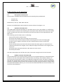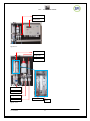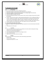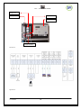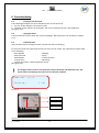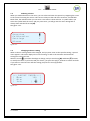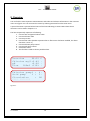
1
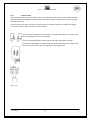
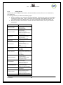
MANUAL SPI-C170 CHLORINE User Manual SPI-C170 CHLORINE SEM Waterbehandeling B.V. De Run 4420 5503 LR Veldhoven Postbus 373 5500 AJ Veldhoven Telefoon: (040) 257 03 40 Telefax: (040) 257 08 92 Email: [email protected] www.semwaterbehandeling.nl SPI – C 170 CHLORINE Index SPI-C170 ............................................................................................................................................. 1 1. INTRODUCTION ........................................................................................................................ 3 2. DESCRIPTION AND OPERATION ................................................................................................. 5 3. SAFETY ..................................................................................................................................... 7 4. TRANSPORT AND STORAGE....................................................................................................... 8 5. ASSEMBLY AND INSTALLATION ................................................................................................. 9 6. COMMISSIONING ................................................................................................................... 11 7. OPERATION ............................................................................................................................ 12 8. MAIN MENU ........................................................................................................................... 14 9. OVERVIEW ............................................................................................................................. 15 10.CALIBRATION ........................................................................................................................ 16 11.SETTINGS............................................................................................................................... 27 12.ALARMS ................................................................................................................................ 36 13.MANUAL OPERATION ............................................................................................................ 43 14.REPORTS ............................................................................................................................... 45 15.MAINTENANCE ...................................................................................................................... 48 16. CONFIGURATION .................................................................................................................. 51 17. DECOMMISSIONING ............................................................................................................. 58 18. DISCARDING ......................................................................................................................... 59 V1 20130904 1 SPI – C 170 CHLORINE Foreword: The manual for the SPI-C170 is meant for the following authorized employees: - Electrotechnical staff Watertechnical staff Laboratory staff This manual is made for the installation and operation of the SPI-C170 Chlorine. In this manual you will find various enumeration characters: (-) (1.) - Enumeration of functions To be performed actions Please read this manual thoroughly Only let authorized staff work with the SPI-C170 Make sure the manual is available for every user In case of emergency, please contact your supplier Limited warranty This manual is made with care, although SanEcoTec is not taking any responsibility according the consequential for any failures made in this manual. Copyright notice All rights reserved. No part of this publication may be reproduced, stored in a retrieval system, or transmitted, in any form, by any means, electronic, mechanical, photocopying, recording or otherwise without permission in writing from your supplier. V1 20130904 2 SPI – C 170 CHLORINE 1. Introduction 1.1 Purpose of the SPI-C170 The SPI-C170 is designed for correctly measuring, controlling, and guarding a water treatment process. The SPI-C170 is suitable for the following sectors: Water companies Other locations that measure and regulate Chlorine levels 1.2 Important specifications The most important specifications of the SPI-C170 are: Measuring the Chlorine level Measuring the pH level Measuring the flow Controlling the dosing pumps for Chlorine and acid Flow protection (No flow, no dose) Circulation contact protection A supply voltage of 12VDC reagents colour Specifications of the measurable parameters: Chlorine Method: reagents colour pH Method: pH gel-electrode Flow Method: Via pulse or current sending flow meters like VDO or INEL (if your type isn’t mentioned, please contact your supplier) Measurement Chlorine Method Reagents colour Range 0 -2,5 mg/l pH Flow Electrode Pulse or Current 1 - 14 pH 0 – 100 % The accuracies are based on strict adherence to the procedures in this manual. V1 20130904 3 Accuracy 0 – 1 mg/l ± 0.05 1 – 2,5 mg/l ± 0.1 ± 0.05 pH ± 1% SPI – C 170 CHLORINE 1.3 Warnings The SPI-C170 is designed and produced with the greatest care. However, you should take into account that: - The SPI-C170 makes use of dangerous and harmful chemicals. No higher supply voltage than 12VDC is used. 1.4 Background information After years of collaboration with a team of specialists in the field of water treatment, the SPI measure and control system was introduced. The SPI-C170 is the fourth generation of its kind. The SPI-C170 is a water control system based on the colorimetric measuring method that utilizes reagents colour discoloration. The intensity of the discoloration after a measurement with the reagent is a measurement of the quantity of Chlorine in the water. The greatest advantage of colorimetric measuring is that it is not affected by external factors like pH and flow. 1.5 Conditions of use Surroundings free of aggressive vapours Temperature of the room housing the SPI-C170 is between 5C - 40C Relative humidity not > 80% No condensation V1 20130904 4 SPI – C 170 CHLORINE 2. Description and operation 2.1 Description of the SPI-C170 The SPI-C170 is supplied and preassembled on one assembly plate provided with: 1 Control-unit 1 Analysis-unit Dimensions (L x W x H) = 480 x 480 x 100 mm All parts are installed either water technical or electro technical. See figure 2.1.1. 2.2 Operation of the SPI-C170 The sample water is fed into the buffer jar. The buffer serves, as the name implies, as a buffer from where the water can flow to the measuring cell. The surplus water will flow back to the pool’s buffer system. The SPI-C170 will run the measurements of the water within a freely adjustable time. See figure 2.2.1. The measuring cycle of the SPI-C170 is as following: Empty cell of previous measurement Fill cell with the sample water and empty once more (rinse) Fill cell with to be measured water and start measuring the zero value and empty again Provide a shot of reagent, and fill the cell with a limited supply of water, measure the discoloration Fill the cell with some extra water and measure the discoloration again (2nd measurement to check the saturation of the reagent, and to adapt the reagent valve time to save reagent), then empty cell Fill cell with the to be measured water and empty once more (rinse) Fill cell fully with water The drain valve empties the cell after every step. That water exiting the cell is led to the sewer. 2.3 Software structure of the SPI-C170 The SPI-C170 makes use of simple operating software. The complete operation is executed using the buttons on the unit. The display shows measured values and settings. The hardware features an internal memory wherein data, reports, and calibration settings are stored. This data is available on demand and provided with a date and time of occurrence. When you have the optional SPI-REMOTE software, it is possible control and see the information of the SPI using the network or internet. With the optional SPI-GRAPHS software, you can use the data downloaded with the remote software, and use this for data acquisition. V1 20130904 5 SPI – C 170 CHLORINE Analysis-unit Control-unit Figure 2.1.1. Buffer jar Reagent vial Filling tube Drain tap Supply valve Reagent valve Drain valve Overflow tube Filter Figure. 2.2.1 V1 20130904 6 SPI – C 170 CHLORINE 3. Safety 3.1 Safety regulations The SPI-C170 is as careful as possible designed with the eye on safety. We tried to reduce the safety risks to a minimum. The SPI-unit is supplied with a 12VDC adapter via a power outlet. While the SPI-unit and the analysis-unit are placed next to each other, the water is not interfering with the electrical systems. Using the remote software (optional) you can use our services to provide assistance over distance 3.2 Risks We would like to appoint the remaining risks. You need to handle these carefully by fully instructed and authorized staff: Refilling the reagent Cleaning spilled compound Store reagent in a cool, dark environment, provided with instructions. Keep the SPI-unit and the analysis-unit clean from any remaining reagent, because this will create stains with time. 3.3 Personal protective equipment Wear while in direct contact with the reagent safety glasses, latex gloves and protective clothing. 3.4 R-S sentences Reagents colour R36/37/38 Harmful to the eyes, respiratory system and skin. R25 Causes severe burns. S2 Keep out of reach from children. S20 Do not eat or drink. S24/25 Avoid contact with the skin and eyes. S45 In case of accidents, immediately seek professional help. V1 20130904 7 SPI – C 170 CHLORINE 4. Transport and storage 4.1 Disassembly To disassemble the SPI-C170, follow the following procedure: 1. Remove the adapter from the power outlet so that the unit is powerless. 2. Remove the reagent vial from the holder (watch out for spilling reagent from the tube). 3. Empty the reagent vial, and seal it with the cap. 4. Empty the buffer jar using the drain tap. 5. Remove possible pH electrodes and store these for later use (don’t forget the protective cap with KCl-solution). 6. Flush the valves with clean water or when possible, distilled water. Do this by filling the buffer jar with this. Especially the reagent valve needs extensive cleaning. The reagent will cristalize when it dries. Do this by replacing the reagent vial with a container of clean water. Now control the valves a few times. See chapter 10.1.4.3 Times & test, and for the reagent valve chapter 10.1.4.2. 7. Flush the analysis-unit well with clean water, then make sure the unit is empty and dry. 8. Clean all tubes with clean water and dry. 9. Remove all inserted cables from the SPI-unit. 10. Before the taking the assembly plate off the wall we point out once more that all parts should be dry. 11. Take the SPI-unit off the wall. 4.2 Transport 1. After disassembly, make sure the SPI-unit is placed in a firm box, with the components facing upwards. This may also be standing upward. 2. Protect the corners well from impacts. 3. Cover the upward facing components with filling or air foil. 4. Close the box with tape. 5. Make sure the box remains free from damage. 4.3 Storage While storing make sure the environment meets the following requirements: Moisture free Free of corrosive vapours Temperature between 5C - 40C V1 20130904 8 SPI – C 170 CHLORINE 5. Assembly and installation The assembly and installation of the SPI-C170 is described in the following paragraphs. On the right side of the pages you’ll find pictures or schemes that will clarify the text. 5.1 Assembly The SPI-C170 consists of 2 main units: Control-unit Analysis-unit See figure 5.1.1. 5.2 Installation The SPI-C170 is completely preassembled on one assembly plate provided with the units as named in chapter 5.1. Check prior to installation: The water supply is taken care of and brought to where the SPI is going to be The power outlet is in an acceptable range of the SPI-unit (100-240VAC 47-63Hz) The return to the buffer tank is taken care of and brought to where the SPI is going to be The drain to the sewer is taken care of and brought to where the SPI is going to be Please follow the instructions for installing the SPI-C170: 1. Remove the SPI from the box. 2. Check if the cables are installed correctly in the cable glands 3. Mount the assembly plate to the wall. 4. Connect the water supply to the buffer jar, and provide enough flow (minimal 5 L/h). 5. Connect the return to the buffer tank to the buffer jar. 6. Connect the drain to the sewer to the buffer jar. 7. Connect the cables from the control unit as in figure 5.2.1. Supply: supplied adapter pH electrode Flow measurement 4-20 mA signal Flow measurement pulse signal Circulation contact Disinfection pump (Chlorine) Acid pump Supply water contact Alarm contact Cell contacts (LED and receiver) Valve contacts (supply, drain and reagent) 8. Place a vial of reagents colour in the holder, apply the cap, and insert the reagent tube through the cap. 9. The SPI-C170 can now be commissioned V1 20130904 9 SPI – C 170 CHLORINE Reagent vial Analysis-unit Buffer jar Control-unit Supply and drain Figure 5.1.1. Figure 5.2.1. V1 20130904 10 SPI – C 170 CHLORINE 6. Commissioning 6.1 Turning on the SPI-C170 The following procedures are to be followed to turn on the SPI-C170: 1. Put the 12 VDC adapter in the power outlet. 2. The boot screen appears on the display. The current software version is also displayed. See figure 6.1.1. 6.2 Language choice The SPI-C170 can be set to work with various languages. More about this can be found in chapter 15.4. 6.3 Indication LEDs After the SPI-C170 has configured itself, the blue LED will start flashing. On the front panel of the SPI-C170 control-unit are a total of 3 LEDs. The explanation of these LEDs are as following: Blue ON/OFF ; Working Red continued ; Alarm Red ON/OFF ; Turned off alarm Orange short ; Measuring Orange continuous ; Manual operation active See figure 6.3.1. ! The images of the screens in this manual are for presentation and indication only. The shown values and settings may not be correct for your situation. SEM SPI Version: C170 1.00 Figure 6.1.1 Tag plate Indication LEDs Display Figure 6.3.1 V1 20130904 11 SPI – C 170 CHLORINE 7. Operation 7.1 Navigation Using the keyboard, you can perform all operations. You simply follow the options through the menu structure on the display. Navigating through the menu structure is done using the arrow buttons. The display displays a maximum of 4 lines a time. The menus often contain more information or possible choices. To display these, you can browse through using the arrow buttons. Page up with the arrow ‘up’ ( ). Page down with the arrow ‘down’ (). Page back with the arrow ‘left’ (). Confirming a selection with ‘enter’ ( ). Confirming is performed using the ‘tick’ (). To go back the the main menu, or cancel certain settings, you use the cross mark (). See figure 7.1.1. ! To return to the main menu after every step, press (). Navigation buttons Confirming Main menu/ cancel Figure 7.1.1. V1 20130904 12 SPI – C 170 CHLORINE 7.2 Selecting a choice When you made a decision in the menu, you can select and enter this option by navigating the cursor to the correct line using the arrows. This cursor is always at the end of the sentence, and will flash. Most often, the indication that you can enter a next menu is done with the ‘>’ symbol. When you select this symbol with the cursor and you press enter, you will go into this menu. Going back is always done with the left arrow (). See figure 7.2.1. Overview Calibration Settings Alarms ▓ > > > Figure 7.2.1. 7.3 Changing a value or setting When a value or setting needs to be changed, and you press enter on that specific setting, a special menu appears. This menu displays the current setting, as well as the minimum and maximum settings this value can have. With the cursor (▓) you select what digit to change, and you use the up () and down () buttons to modify the value. If you have made your choice, you press the tick () button to confirm and safe. If you want to cancel and not safe the setting you press the cross () button. See figure 7.3.1. |--_ADJUST VALUE ---| | Max: 100 | | Min: 0 | | Set: [ 8 ▓] | Figure 7.3.1. V1 20130904 13 SPI – C 170 CHLORINE 8. Main menu Using the main menu, all important functions of the SPI-C170 can be reached. The main menu is what you get to see after starting the SPI-C170, and is where you always get back to. The main menu consists of the following options: Overview – in this menu, the most important measurements and current alarms are displayed Calibration – in this menu you can calibrate specific measurements connected to the SPI-unit Settings – All kinds of settings to regulate the operation of the SPI Alarms – Gives a status of the current alarms that may or may not be active Manual operation – Here to possibility will be given to operate the SPI-C170 in automatic, semi-automatic or manual mode Reports – A variety of reports of specific functions and measurements Maintenance – The maintenance mode can be activated here Configuration – Important options concerning the hardware setup of the system and more See figure 8.1. The main menu is where you end up after pressing the cross () button. Overview Calibration Settings Alarms > > > > Manual operation Reports Maintenance figure 8.1. Configuration > > > > V1 20130904 14 SPI – C 170 CHLORINE 9. Overview You can find the most important measurements and values and relevant information in the overview menu as in figure 9.1. You can enter this menu by selecting Overview from the main menu. A special character is present behind some of the lines indicating its status. More about these characters can be read in chapter 12.1. The lines respectively represent tie following: 1. Current time and general alarm status 2. Current Chlorine value 3. Current pH value 4. Current Flow value (Dashes represent that no flow sensor has been installed, the alarm character is now ‘X’) 5. Current Chlorine pump control 6. Current acid pump control 7. Circulation status 8. The final line is able to show a possible alarm. Overview 09:35 Chlorine mg/l:0.82 pH :6.92 Flow 180m3 :116% Chlorine pump% : Acid pump % : Circulation : CELL FAILURE C . . . 4. 3. OK Figure 9.1. V1 20130904 15 SPI – C 170 CHLORINE 10.Calibration All measurements connected to the SPI-C170 must be regularly checked and, if necessary, be calibrated. This ensures the quality of the measurements made. You can enter this menu by selecting Calibration from the main menu. Calibrating the measurements is done by using calibrated third party equipment. The following measurements can be calibrated on the SPI-C170 Chlorine: Chlorine Calibration pH Chlorine > See figure 10.1. pH > Figure 10.1. 10.1 Chlorine At the procedure of calibrating Chlorine you are able to choose between 2 different methods of calibration: With handmeter (a relatively fast method to calibrate Chlorine measurement using a handmeter) With fluids ( a method to calibrate the Chlorine measurement using professional calibration fluids) Next to calibrating you can also choose for: Restore calibration (restores the calibration settings to the factory settings) Settings (various settings for controlling the valve times, checking the current cell values and Chlorine calibration refilling the reagent vial) SeeWith figure 10.1.1. handmeter > With fluids Reset calibration > Settings > V1 20130904 16 SPI – C 170 CHLORINE Figure 10.1.1. 10.1.1 Calibrating with handmeter When you select Calibrating with handmeter the menu as in figure 10.1.1.1 will appear. Here you can perform a calibration using a third party handmeter. Now perform the following instructions: 1 Take a sample from the drain tap under the buffer jar and measure this with the handmeter. Refer to the handmeter’s instructions here. 2 Compare the value of Current with the measurement of the handmeter. If there is a big difference between the current and metered values, press enter ( ). 3 You now get to see the Adjust Value screen where you must enter the correct metered value at Set 4 Press the tick () now. 5 The measurement has been calibrated. ! Start calibrating the measurement only after at least one measurement has been performed. Otherwise this could cause a wrong calibration. Hand calibration Current : 0.69 mg/l Metered : 0.65 mg/l Press (V)to save Figure 10.1.1.1. V1 20130904 17 SPI – C 170 CHLORINE 10.1.2 Calibrating with fluids Calibrating using fluids guarantees a more dependable calibration then when using a handmeter. The system lets you first perform a zero point measurement, and after that a measurement using a control fluid of your choice. The measurement will then be calibrated at 2 points. To calibrate with fluids, select calibrating with fluids, the menu as in figure 10.1.2.1 will appear. Fluids calibration Current : 0.50 mg/l Cal at : 0.52 mg/l Begin 0 mg/l calib > Figure 10.1.2.1 Follow the following steps to calibrate with fluids: 1 Make sure you have the correct control fluids and tools within reach. Here we will use a control fluid of 0.52 mg/l. Select the line Cal at … mg/l and press enter ( ). Fill in the value of your control fluid in mg/l, and confirm with the tick (). Now select Begin 0 mg/l calibration and press enter ( ). The menu of figure 10.1.2.2 now appears. Calibration at 0mg/l Expect : 980-1015 mV Actual : 964 mV Begin 0.52mg/l cal > Supply valve Drain valve Colour valve Remeasure > > > > Figure 10.1.2.2. When you scroll down you have free use of the valves. Just select and press enter ( ). Use the supply valve to fill the cell with water. Now select Remeasure and press enter ( ). The actual value now needs to show between 980 and 1015 millivolt (mV). V1 20130904 18 SPI – C 170 CHLORINE If the value is correct, select and press enter ( ) on Begin 0.52 mg/l cal. The menu of figure 10.1.2.3 now appears. Cal at 0.52 mg/l Value : 0.51 mg/l Expected: 0.52 mg/l Press(V)to save Figure 10.1.2.3 Supply valve Drain valve Colour valve Remeasure > > > > 6 7 Rinse the cell a few times by alternating the use of the supply valve and the drain valve. Fill the cell with your chosen control fluid. You can either simply pour it gently in the filling tube, or injecting it with a tool. Now select Remeasure and press enter ( ). The cell will now start measuring the control fluid. The value needs to show a result close to 0.52 mg/l. If this is not the case, try to recalibrate again. Otherwise, select Press (V) to save, and press the tick () to save the calibration. 8 The measurement is now calibrated. ! Start calibrating the measurement only after at least one measurement has been performed. Otherwise this could cause a wrong calibration. V1 20130904 19 SPI – C 170 CHLORINE 10.1.3 Reset Calibration If you are not satisfied with the current Chlorine calibration or you don’t have the right tools to calibrate, you can reset the calibration settings to the factory settings. To do a calibration reset, select Restore calibration from the Chlorine calibration menu. The screen from figure 10.1.3.1 will now appear. Reset calibration To perform a restore, press the tick () while in this screen, the Chlorine calibration will then be restored to its factory settings. ! 1 After restoring the calibration to its factory settings, it is important to check the calibration as soon as possible. Reset calibration Proceed press (V) Figure 10.1.3.1. 10.1.4 Settings When you select Settings from the Chlorine calibration menu, the menu as in figure 10.1.4.1 will appear. In this menu are a few advanced options and settings for the Chlorine calibration. You can make a choice out of the following options: Cell values (gives a quick overview of the current cell values) Colour empty (when the vial of reagents colour is empty or near empty, this menu helps you replace it) Timing & test (You will be able to test and control the valve times in this menu) Cell values Colour empty Timing & test > > > Figure 10.1.4.1. V1 20130904 20 SPI – C 170 CHLORINE 10.1.4.1 Cell values When you select Cell values from the Chlorine settings menu, the menu as in figure 10.1.4.1.1 will appear. In this menu it is possible to check the current cell values: 1. Cell null: the zero value of the measuring water without reagents colour. 2. Cell active: the value of the measuring water with the reagents colour added. 3. Cell 2e ctrl: The value of the measuring water with the reagents colour added, plus a little more measuring water added. 4. Colour time: the current opening time for one shot of colour reagent. Cel null : Cel active : Cell 2e ctrl: Color time : 981 512 531 18 > > > > Figure 10.1.4.1.1. 10.1.4.2 Resupply reagent When you select Colour empty from the Chlorine settings menu, the menu as in figure 10.1.4.2.1 will appear. In this menu it is possible to replace the vial of reagents colour. The cell is preparing itself for replacing the vial now. To avoid air bubbles in the reagent supply tube to the analysis-unit, the reagent first has to be guided through the tube before use. ! Prior to replacing the vial, check if the supply tube is completely filled with reagents colour. If this is the case, you can skip the steps mentioned underneath, and simply switch the vial, and stick the tube back in If the supply tube is dry because it is for example just out of storage, the following steps need to be taken: 1. Take out the tube of the old vial, and take the vial out of its holder. Check if there is still some reagent left, you can reuse this. 2. Take a new vial and place it in the designated holder on top of the analysis-unit. 3. Replace the standard cap of the vial and replace this with the cap supplied with the SPI-C170. This cap contains 2 holes; one for the tube, the other for aeration. 4. Insert the supply tube through the hole in the cap; make sure the end of the tube reaches the bottom of the vial. Preparing cell Figure 10.1.4.2.1 Wait 6 sec…… Put your finger on top of tube. Press (V) V1 20130904 21 SPI – C 170 CHLORINE 5. By now the menu as in figure 10.1.4.2.2 has appeared. The cell is prepared. 6. You are asked to place your finger on the top of the filling tube. Do this and ensure an airtight seal. See figure 10.1.4.2.3. Place your finger here Reagent tube Figure 10.1.4.2.3 7. Now press the tick (). Button. The colour valve and the drain valve will open now. Because of the pressure difference, the reagents colour will be sucked down to the cell. The tube is now free of air. ! ! Warning! Chlorine reagents colour contains a strong acid. Make sure you have the right tools and protection. Clean up spills directly and work preferably with gloves. It is advised when replacing the enmpty reagent vial with a new one, to clean the cell with a cotton swab. Remove the filling tube temporarily (when there’s no fluids in the tube remaining), moisten the swab lightly with clean water, and clean the cell. Then start replacing the reagent vial like normal. This keeps the cell in condition. V1 20130904 22 SPI – C 170 CHLORINE 10.1.4.3 Timing & testing When you select Timing & test from the Chlorine settings menu, the menu as in figure 10.1.4.3.1 will appear. In this menu it is possible to change the times that the valves will be open to supply water, reagent, or drain. The following functions can be performed here: Supply time (the time the supply valve will be opened in tenths of a second. Setting this as 10 means an opening time of 1 second.) Test supply (tests the water supply valve with the above set time) Colour time (the time the colour valve will be opened in hundreds of a second. Settings this as 19, means an opening of 0,19 second. Setting as 0, means automatic reagent dosing) Test colour (tests the colour supply with the above set time) Drain time (the time the drain valve will be opened in tenths of a second. Setting this at 100, means an opening of 10 seconds) Test drain (tests the drain valve with the above set time) Rinse time (the time the supply valve will fill the cell and the filling tube in seconds. Setting this at 100, means a rinse time of 10 seconds) Test rinse (tests the rinse time with the above set time) Cycle time (The time the SPI-C170 will ‘wait’ between 2 measurements in seconds. Setting this at 300, means that the SPI will wait 5 minutes, before the next measurement starts. ! If the colour valve time is set at 0, the automatic reagents colour dosing is activated. This means that the dosing of a shot of reagent colour will be adapted to the use of the reagent. This saves reagents colour. V1 20130904 23 SPI – C 170 CHLORINE Cycle timing & test Supply time 0,1s 10 Test supply > Colour time 0,01s 19 Figuur 10.1.4.3.1 Test colour > Drain time 0,1s 100 Test drain > Rinse time 0,1s 100 Test rinse Cycle time 1 s > 300 ! The cycle time is responsible for the quantity of measurements. A low time here means more measurements, but also more reagents colour use. More time means fewer measurements, but it saves more reagents colour. ! The SPI-C170 will temporary stop measuring and controlling as long as this menu is opened. The pumps will remain pumping at the same level as before this menu was opened. Therefore, close this menu when ready with the timing settings. V1 20130904 24 SPI – C 170 CHLORINE 10.2 pH When you select pH from the calibration menu, the menu as in figure 10.2.1 will appear. In this menu it is possible to calibrate the pH. For calibrating the pH value, it is important to have the right tools at hand. The pH is calibrated using 2 independent constant buffer solutions with different pH values. Make sure you have these solutions with you before starting the calibration. To check the pH measurement, we advise to have a well calibrated third party handmeter with its own pH electrode. A colorimetric comparison like the phenol-red solution is only an indication, not calibration an pH absolute value Cal. pH 7 at 7.00 Start pH 7 calibr. > Cal. pH 4 at 4.01 Start pH 4 calibr. > Reset pH calibr. > Water temp. C 25 Figure 10.2.1 Take the following steps in order to calibrate the pH: 1. Make sure the pH fluids are at the right temperature Select Calibrate pH 7 at 7.00 and press enter ( ). Either fill in your choice of buffer solution, or leave this unchanged at 7.00. Confirm with (). 2. Take the electrode out of the buffer jar and flush it with clean water. Now select Start pH 7 calibration and press enter ( ). 3. The top screen as in figure 10.2.2 appears. Take your pH electrode and put it in the pH pH solution 7.00of your calibration choice. Probe Hz : 1500 Actual pH : 7.01 Press (V)to save pH 4.01 calibration Probe Hz : 654 Actual pH : 3.99 Press (V)to save V1 20130904 25 SPI – C 170 CHLORINE Figure 10.2.2. 4. 5. 6. 7. 8. 9. Gently stir the electrode through the solution for about a minute. Check the value at Actual pH. Wait for this value to get stable, then confirm with (). Now flush the electrode with clean water. Execute steps 2 -8 with the pH 4.01 calibration (or your own calibration). The pH is now calibrated at 2 points. As final confirmation, we advise to flush the electrode once more, and to put it in the pH 7.00 solution. 10. Press (), and select Overview. Check if the pH is now at 7.00 or very close. 11. Flush the electrode once more, and place it in the buffer jar. V1 20130904 26 SPI – C 170 CHLORINE 11 Settings In the settings menu it is possible to change the settings of specific parts of the SPI-C170. You can enter this menu by selecting Settings from the main menu. You can choose between the following submenus: Chlorine pH Flow Time & date Day/night Sample water pump See figure 11.1. Chlorine pH Flow Time & date > > > > Day/night Sample water pump > > Figuur 11.1 Figure 11.1. V1 20130904 27 SPI – C 170 CHLORINE 11.1 Chlorine settings When you chose for Chlorine settings in the previous menu, you’ll see the screen as in figure 11.1.1. Here you can view or change the following settings: Hi alarm day (when the Chlorine measurement exceeds this value in the dayhours, an alarm will be given) Hi alarm night (when the Chlorine measurement exceeds this value in the nighthours, an alarm will be given) Setpoint day (The setpoint of the Chlorine measurement in the dayhours) Setpoint night (The setpoint of the Chlorine measurement in the dayhours) Lo alarm day (when the Chlorine measurement undershoots this value in the dayhours, an alarm will be given) Lo alarm night (when the Chlorine measurement undershoots this value in the nighthours, an alarm will be given) Critical alarm (when the Chlorine value undershoots this setting, a critical alarm is given, and the pump stops dosing. Something must be very wrong at this point and you should check your installation) Chlorine Hi alarm Hi alarm Setpoint settings day : 120 night : 120 day : 80 Setpoint Lo alarm Lo alarm Critical night day night alarm Alarm del day Delta % Prop factor Int factor s : : : : 80 10 10 5 :1200 : 50 : 3.0 : 200 Pump min % : 0 Pump max % : 80 Max pulse time :1800 Figure 11.1.1. V1 20130904 28 SPI – C 170 CHLORINE ! Alarm del day (The delay in seconds after an alarm will be given. A too short time may cause false alarms when there is a bad measuring present) Delta (this setting controls the maximum and minimum pump setting. The SPI-C170 calculates the average pump control. The pump cannot go over xx% of this average value) Prop factor (his setting controls the proportional gain of the Chlorine controller system. The SPI-C170 constantly calculates the difference between the setpoint and the actual Chlorine value. The more difference the harder or slower the pump will go. The factor filled in here is the amount of amplification of the gain. The proportional factor is engaging with the integration time) Int factor s (this setting controls the integration time of the Chlorine controller controller system. The integration time adds or subtracts a percentage of the pump’s control every time the set time has expired. The integration factor is only working when the set point differs from the measured value. This setting is used for slowly reaching the desired set point, when the proportional gain is not responding all that much) Pump min % (the minimum percentage at which the pump will work) Pump max % (the maximum percentage at which the pump will work) Max pulse time (the maximum time at which the pump can pump on maximum setting. If after this time the pump is fully pumping, and the measured value still has not reached the desired set point, there must be something wrong) Delta, proportional gain, and integration time are advanced settings. They affect the control system and how efficient a specific system is controlled. V1 20130904 29 SPI – C 170 CHLORINE 11.2 pH settings When you chose for pH settings in the settings menu, you’ll see the screen as in figure 11.2.1. Here you can view or change the following settings: Hi alarm day (when the pH measurement goes over this value in the dayhours, an alarm will be given) Hi alarm night(when the pH measurement goes over this value in the nighthours, an alarm will be given) Set point day (The set point of the pH measurement in the dayhours. Set point night (The set point of the pH reading in the Lo alarm day (when the pH measurement drops under this value in the dayhours, an alarm will be given) Lo alarm night (when the pH measurement drops under this value in the nighthours, an alarm will be given) Alarm Del day (The delay in seconds after an alarm will be given. A too short time may cause false alarms when there is a bad reading present) Delta (this setting controls the maximum and minimum pump setting. The SPI-C170 calculates the average pump control. The pump cannot go over xx% of this average value) Prop factor (his setting controls the proportional gain of the pH controller system. The SPIC170 constantly calculates the difference between the setpoint and the actual pH value. The more difference, the faster or slower the pump will work. The set factor here is the amount of amplification of the gain. The proportional factor is engaging with the integration time) Int factor s (this setting controls the integration time of the pH controller system. The integration time adds or subtracts a percentage of the pump’s control every time the set time has expired. The integration factor is only working when the setpoint differs from the measured value. This setting is used for slowly reaching the desired setpoint, when the proportional gain is not responding all that much) pH settings Pump min % (the minimum percentage at which the pump will work) Hi alarm day : 7.50 Hi alarm night: 7.50 Setpoint day : 6.80 Setpoint night: Lo alarm day : Lo alarm night: Alarm del day : Delta % Prop factor Int factor s Pump min % V1 20130904 6.80 6.00 6.00 1200 : 50 : 1.0 : 180 : 0 30 SPI – C 170 CHLORINE Figure 11.2.1 Pump max % (the maximum percentage at which the pump will work) Max pulse time (the maximum time at which the pump can pump on maximum setting. If after this time the pump is fully pumping, and the measured value still has not reached the desired setpoint, there must be something wrong) ! Delta, prop factor, advanced settings. They affect the control system and Pump max % and int factor : are80 how efficient a specific pool is controlled. Max pulse time :1200 V1 20130904 31 SPI – C 170 CHLORINE 11.2 Flow settings When you chose for Flow settings in the settings menu, you’ll see the screen as in figure 11.3.1. Here you can view or change the following settings: Alarm % (when the flow falls below this value, an alarm will be given) Alarm delay sec (the delay in seconds after which an alarm will be given) Dose stop % (when the flow falls below this value, the acid pump will stop dosing, something must be wrong) Dose stop delay (the delay in seconds before the acid pump will stop pumping after the dose Flow settings stop error) Alarm % : 60 Alarm delay sec: 300 Dose stop % : 50 Dos stop delay : 1 Figure 11.3.1 11.3.1 Advanced flow settings Flowsensors are sensors that send out voltage pulses or a current. The frequency in Hertz (Hz) of those pulses, or the amount of current (mA) is proportional with the flow. You can fill in the correct value in the System setup of the Configuration menu. When you have a flowsensor that uses pulse signals, you need to fill in the maximum amount of m3/h at 30Hz in the m3/h at 30Hz option in chapter 16.1. When you have a flowsensor that uses current signals, you need to fill in the maximum amount of m3/h at 20mA in the m3/h at 20mA option in chapter 16.1 Next, you need to fill in the amount of cubic litres of water each hour when the flow should be at 100% in the m3/h at 100% option in chapter 16.1. This information should be in the design plans you got supplied with your system by the installer. Example calculating pulse sending sensors When the flowmeter is sending pulses, the flow in m3/h at a sensor frequency of 30Hz is to be calculated as below: F = 0,004875 x D² ( VDO flowsensor ) F = 0,003140 x D² ( INEL flowsensor ) V1 20130904 32 SPI – C 170 CHLORINE Wherein: F = the flow at a sensor frequency of 50Hz in m3/h. D = the internal diameter of the tube the flowsensor is installed in, in mm Example: Bürkert sensor type 8020 30Hz corresponds to 1m/s. Tube diameter 50mm, fill in the number 6 at (m3/h bij 30Hz). Diameter 50 63 75 90 110 125 140 160 200 225 250 Flow m3/h (at v=1m/s) 6,0 9,5 13,5 19,4 29,0 37,4 46,9 61,3 95,7 121,2 149,8 11.4 Time & date settings When you chose for Time & date settings in the settings menu, you’ll see the screen as in figure 11.4.1. Setting the right time is important, because the correct operation of the SPI-C170 is dependable on this setting. If the date or time settings are not correct, the system could be able to load different day/night settings at the wrong moments. The date and notes that would be written in the reports and logs would be wrong too. Here you can view or change the following settings: Minutes (the minutes of the current time) Hour (the hours of the current time) Day (the days of the current date) Month (the months of the current date) Year (the years of the current date) It could happen that the SPI-C170 has reset the date & time settings at a power failure. If this is the case, the SPI will counting from it’s default date and time values. The cause of this is most likely Time & start date a bad battery. Contact the supplier if you suspect Minutes : 28 this. Hour Day : : 8 22 Month Year : : 4 2011 V1 20130904 33 SPI – C 170 CHLORINE Figure 11.4.1. 11.5 Day/night settings Day start hour : 7 Day start min settings : in the0settings menu, you’ll see the screen as in figure 11.5.1. When you chose for Day/night Night start hour: 21 Night start min : 0 Figure 11.5.1. These settings make different settings for day/night times of the system possible. For example, at night, you could set a lower value for the Chlorine setpoint You can find these settings in the Chlorine or pH settings as explained in chapter 11.1 and 11.2. V1 20130904 34 SPI – C 170 CHLORINE 11.6 Sample water Pump When you choose for Sample water Pump settings from the Chlorine settings menu, the screen as Sample water pump figure 11.6.1 will appear. In this menu it is possible to set economize the function of the sample Time : 5 water pump. min Figure 11.6.1. The sample water pump menu has 3 functions: Removing of ‘old’ sample water out of the sample water conduit after a system start Saving of sample water Increasing lifetime of pump This function operates as following: 1. When the SPI-C170 is started, the sample water contact is activated, and the pump starts pumping, the timer will run. 2. The sample water can now flow through the conduit for a while, so that fresh water is flowing through the buffer jar. 3. After the set time has expired, 5 minutes in our example, the SPI will start the first measuring cycle. 4. After the measurement, the SPI will be in the resting period cycle, and the sample water pump is turned off. 5. When the resting period cycle is over, the pump will be turned on again, and the 5 minute timer lets the water flow again. After that, it’s time for another measurement. Setting Fill in at Time min the total duration in minutes the pump will run before the measuring cycle starts again. ! If you don’t want to use this function, set the time at Time min to 0. The SPI will the function as normal. When you set a long time, keep in mind this will extend the total measuring cycle, it is only profitable when you have a long cycle time. V1 20130904 35 SPI – C 170 CHLORINE 12.Alarms All current alarms and their alarm values will be shown in the Alarms menu. If an alarm has presented itself, the red LED will light on the keypad of the SPI-C170. You can enter this menu by selecting Alarms from the main menu. When you select alarms, the screen as figure 12.1 will appear. The alarms will be shown in the following format: 1. The date and time of the event. 2011-03-22 10:24 2. The alarm code and the description. A03: pH HIGH 3. The value at which the alarm went off Alarm value = Acknowledge 7.81 [V] Figuur 12.1. 12.1 Alarmcodes and characters Depending on each alarm, action will be taken. The alarms come with a code. These alarmcodes and how to solve them can be seen in chapter 12.3 During an alarm situation it can occur that an alarm will not be directly given. This is possible by setting alarm delays. When a measurement returns back to a non-alarm state, the alarm will void. You can read these alarms back in the alarm reports. For this we link you to chapter 14. If you start fixing the alarm cause, you can select Acknowledge to turn the alarm off using the (). The alarm will then be acknowledged and the red alarm LED will flash now. In the Main menu all main measurements and important functions are shown together with their current status. The character behind each line is an indication of how this part functions. The following characters can be seen: V1 20130904 36 SPI – C 170 CHLORINE Character Description . No alarms, all OK v Prealarm A Alarm M Manual operation X Not present or maintenance mode c Pollution alarm is turned off C Cell is polluted *NO Alarm ALARMS ACTIVE* a is turned off No alarms (.) The measurement is within alarm boundaries. No alarms are present. See figure 12.1.1. Figure 12.1.1. Pre alarm (v) The measurement is outside of one of the alarm boundaries. A pre alarm is being made. If there are any alarm delays set, these will start counting now. If the measurement will go in the alarm boundaries again, the pre alarm disappears. The alarm delays can be set in the menu Settings. Alarm (A) The measurement has reached outside of the alarm boundaries and does not fall back into the safe zone while the alarm delay has expired. An alarm is made and the red status LED will light up. You can check this alarm in the menu Alarms and a report is made. Turned off alarm (a) The alarm has been seen by the user, and he has turned it off by acknowledging. This way he notifies others that the alarm is being worked on. The red LED will flash. Manual operation (M) The measurement or parts is being manually controlled. This character can also be seen behind the flow measurement. In this case, the flow protection is turned off. More about this in chapter 13. Not present or maintenance mode (X) This character indicates the measurement is not present on the SPI and has been turned off. It can also mean the user is making maintenance on this part. Cell pollution is turned off (c) The measuring cell is becoming polluted and the zero water measurements are getting low. The cell needs to be cleaned. V1 20130904 37 SPI – C 170 CHLORINE Cell is polluted (C) The measuring cell has become polluted on a level where it affects the measurements, the cell needs to be cleaned as soon as possible. V1 20130904 38 SPI – C 170 CHLORINE 12.2 Alarm contact The SPI-C170 contains an alarm contact. This is a potential free contact that can be used to transmit the alarm signals to equipment of third parties. The alarm contact is closed when an alarm is being detected on the SPI. You can connect the alarm contact from the SPI-C170 to an alarm centre for example. See figure 5.2.1 from chapter 5.2 for the location of this contact. You are able to change the relay function to normally open (NO) or normally closes (NC) using jumper 21 on the circuit board. For more information about connecting and setting of the jumper settings. The contact is adjustable to a night mode. This means that when set to night mode, the alarm contact will not work in night times. See chapter 16.1 Figure 12.2.1 V1 20130904 39 SPI – C 170 CHLORINE 12.3 Solving alarms With correct use and regular maintenance, the least hardware errors will occur. For maintenance, see chapter 15. For solving problems you follow the following steps: 1. Check the problem, you can do this by selecting Alarms from the main menu. You are able to see the active alarm here. If you or someone else has already acknowledged the alarm, you can read this back in the Alarm reports. For more information about this, see chapter 14. 2. Research the alarm with below list. Check if the alarm code matches, and try the solutions mentioned. Alarm A01:Chlorine HIGH A02: Chlorine LOW A03: pH HIGH A04: pH LOW A05: LOW FLOW A06: CHECK CELL A07: CELL FAILURE A08: CRITICAL FLOW A09: ACID PUMP A10: CHLORINE PUMP A11: CIRCULATION A12: Chlorine CRIT. A13: FILTER DIRTY V1 20130904 Solution(s) -Pump settings -Wrong settings -Wrong calibration -Pump settings -Wrong settings -Chlorine tank empty -Defect in the Chlorine supply -Wrong calibration -Pump settings -Wrong controller settings -Acid tank empty -Defect in the acid supply -Pump failure -Wrong settings -Pump settings -Flowmeter defect -Defect in the sample water supply -Wrong flow settings -Starting cell contamination -Cell is dirty -Cell is dirty -Sample water supply defect -Reagents colour valve is leaking in the cell -Cell is defect -Pump settings -Flowmeter defect -Defect in the water supply -Wrong flow settings -Pump settings -Acid tank empty -Defect in the acid supply -pH electrode defect -Pump failure -Chlorine tank empty -Defect in the Chlorine supply -Pump is OFF -Pump defect -Pump settings -Wrong controller settings -Chlorine tank empty -Defect in the Chlorine supply -Filter dirty 40 SPI – C 170 CHLORINE Example On the keypad, the red LED is lighting up. The alarm “A09: pH PUMP” is shown on the Alarm menu. This alarm means that the pump has been at full power for over a course of <1800> seconds (this time is adjustable), and the pH value is still high. This indicated a problem with the dosing. 3 possible solutions are: Pump error Acid tank empty Defect in the acid supply 1. First, check whether or not the pump is still working. Maybe the pump is turned off, or has a power failure. 2. Second, check if the acid supply tank is empty. 3. Third, you should check whether or not the transport from the acid might be defect. There could be a leak. See enclosure A for a more detailed list of alarm information and their solutions. V1 20130904 41 SPI – C 170 CHLORINE 12.4 Hot start When the SPI-C170 has a power failure, or someone removed the adapter from the power outlet, the SPI turns off. The system contains a battery, which keeps the clock set, and if the power comes back on, the SPI will still contain the same settings as before The temporarily turning off of the SPI-C170 with data preservation, is called the hot start As the unit is commissioned for a longer period of time, the battery ages. This is causing the SPI no longer retaining the clock settings. As soon as this seems to be the fact, we advise you to take steps to replace the battery. Information about this is available with your supplier. 12.5 Cold start In extreme cases you must move on to a cold start. A cold start means a complete reset of the SPI-C170 to its factory settings. The default settings are being loaded in the machine. Your own settings need to be saved again. It is therefore advisable to first note down these settings before proceeding. Follow the below steps to perform a cold start: 1. Take the power supply adapter out of the power outlet; 2. Press the () button, and keep it pressed; 3. Put the power supply adapter back in the power outlet, wait until the screen’s backlight lights up, then release the () button. 4. The normal boot screen like figure 12.3.1.1 appears, and the line ‘READING ROM’ flashes. SEM SPI C 170 READING ROM Version: 1.00 Figure 12.3.1.1. V1 20130904 42 SPI – C 170 CHLORINE 13.Manual operation The SPI-C170 contains the possibility to let the user control the Chlorine or the acid pumps on manual or semi-automatic mode. When you select Manual operation from the main menu, the screen as figure 13.1 appears. Manual operation 1)aut 2)hand 3)semi Chlorine mode : 1 Chlorine pump %: 50 pH mode : Acid pump % : Flowprotection : 1 50 1 Figure 13.1. ! Please note that when using manual mode to control your pumps, you should check the quality of the water yourself regularly. 13.1 Modes and settings The SPI has a total of 3 control modes: 1. Automatic (default) 2. Manual 3. Semi-automatic Automatic mode In the automatic mode, the SPI-C170 controls the dosing of chemicals by the measured values. Interference of the user is not necessary. Manual mode In the manual mode, the user controls the dosing of chemicals by settings made by hand. This might be useful when a problem has occurred, or no measurements can be done. The “M” is shown behind the pump signal in the overview menu Semi-automatic mode In the semi-automatic mode, the user controls the dosing of chemicals to the pool by hand. But when the setpoint is reached, the automatic controller overrides the semi-automatic mode and the SPI continues as an automatic system. The “S” is shown behind the pump signal in the overview menu When the manual or semi-automatic mode is active, the orange status LED will light up on the keypad. V1 20130904 43 SPI – C 170 CHLORINE Setting mode The set the right mode for a pump, you select the mode of that specific pump, and press enter ( ). You can fill in the following values for each mode: 1. Automatic 2. Manual 3. Semi-automatic Confirm with (). Setting pulses The following settings are for setting the correct pump capacity in percent. For example, you have a pump with a capacity of a maximum of 120 pulses. Maximum pumping is 100%. When you set the Chlorine/pH pump % at 80% now, the pump will use 80% of those 120 pulses. This means the pump will use 96 pulses at 80%. Filling in the max pump capacity in pulses will be explained in chapter 15. 13.2 Flow protection Optionally, you can turn on (1) or turn off (0) the flow protection. The flow protection makes sure the Chlorine and acid pump will not work when the flow is low or not present at all. When you turn the flow protection off (0), the Overview menu will show an M (Manual) behind the flow reading. V1 20130904 44 SPI – C 170 CHLORINE 14.Reports When you select Reports from the main menu the screen as figure 14.1 appears. In this menu you can read back and check various reports such as: 1. Alarm reports 2. Calibration reports 3. Maintenance services reports 4. Data log reports see figure 14.1. Alarm reports Calibration rpts Miantenance rpts Data logger rpts > > > > Figure 14.1. 14.1 Alarm reports When you select Alarm reports from the previous menu, the screen as in figure 14.1.1 appears. In this screen you can see all logged alarms. The first log you see is the most recent. The log screen consists of a date and time, followed by an alarm code and description. When this alarm was acknowledged before, the final line shows whether or not the alarm was acknowledged. When you want to browse back, you press the () button. When you want to start at the end of the list, you press the () button. The following alarms logs can be seen (see chapter 12.3 for more details): Alarm Description A01: Chlorine HIGH Chlorine max exceeded A02: Chlorine LOW Chlorine min undershot A03: pH HIGH pH max exceeded A04: pH LOW pH min undershot A05: LOW FLOW Flow low A06: CHECK CELL A08: CRITICAL FLOW Zero measurement value low Zero measurement value very low Flow very low A09: pH PUMP Defect in acid supply A10: Chlorine PUMP Defect in Chlorine supply A11: CIRCULATION No circulation A12: Chlorine CRIT Chlorine very low A13: FILTER DIRTY Filters are polluted A07: CELL FAILURE V1 20130904 2011-04-11 12:03 A05: LOW FLOW * ACKNOWLEDGED * Figure 14.1.1. 45 SPI – C 170 CHLORINE 14.2 Calibration reports When you select Calibration reports from the previous menu, the screen as in figure 14.2.1 appears. In this screen you can see all logged calibrations. The first log you see is the most recent. 2011-06-03 14:45 C01: Hand Cl Calibr. Nul: 1008 FAC: 101 Set: 0.79 ACT: 0.81 Figure 14.2.1. The log screen consists of a date and time, followed by a calibration code and description. Also some details of the specific calibration. When you want to browse back, you press the () button. When you want to start at the end of the list, you press the () button. The following calibration logs can be seen: Calibration C01: Hand Cl Calibr. C02: Fluids Cl Cal. Description Chlorine hand calibration Chlorine fluid calibration C03: Cell Calibr. Zero water calibration C04: Cal. Override C06: pH Calibration Calibration overridden Reset calibration factors Chlorine Calibration pH C07: Reset pH Calibr Reset calibration factors pH C05: Reset Cl Calibr Reading the calibration report Under the time and calibration code are the following values: 1. NUL (zero value of the measuring water) 2. FAC (calibration factor) 3. SET (calibrated value) 4. ACT (current value) The FAC is a factor that represents the current measurement calibration, and how it differs from the previous calibration. It indicates whether the calibration is adjusted up (>100) or down (<100). The default value is 100, when no calibrations are made. When a calibration is done, the current value is measured: the ACT. After that, you are asked to fill in the hand measured value: the SET. V1 20130904 46 SPI – C 170 CHLORINE 14.3 Maintenance reports When you select Maintenance reports from the previous menu, the screen as in figure 14.3.1 appears. In this screen you can see all logged maintenance services. The first log you see is the most recent. The log screen consists of a date and time, followed by a system code and description. Also some details of the specific system message. 2011-04-11 12:03 R01: System reset Figure 14.3.1. When you want to browse back, you press the () button. When you want to start at the end of the list, you press the () button. The following maintenance logs can be seen: Event Description R01: System reset System reset “hot start” R02: Cold start R03: Maint started System reset “cold start” Maintance started R04: Maint stopped Maintenance stopped R05: Maint timeout Maintenance timed out R06: Software reset Software reset 14.4 Data log repors When you select Data log reports from the previous menu, the screen as in figure 14.4.1 appears. In this screen you can see all logged data from the readings of that moment. The first log you see is the most recent. 2011-04-11 12:03 Chl 0.81 pump 61 % pH 6.80 pump 9 % Flow 112 % Figure 14.4.1. The log screen consists of a date and time, followed by a system code and description. Also the following details on the moment of logging: The Chlorine value in mg/l The Chlorine pump action in % The pH value in % The acid pump action in % The flow value in % When you want to browse back, you press the () button. When you want to start at the end of the list, you press the () button. The data logger registers every once in a while the value of the previously mentioned values and pump actions. The time between every log is adjustable. This Log period can be changed under System setup. For more information about this we link you to chapter 16. V1 20130904 47 SPI – C 170 CHLORINE 15.Maintenance Whenever maintenance needs to take place on the SPI-unit, and you need to detach/replace critical parts, you can start a maintenance session in the menu Maintenance from the main menu as seen in figure 15.1. Maintenance Start Stop Remaining (1800) > > : 1639 Figure 15.1 To perform maintenance, select Start and press enter( ). Now the maintenance timer will start counting. You get a standard time of 1800 seconds or 30 minutes to do your maintenance. During this time, the SPI won’t send out alarms 15.1 Regular maintenance For correct operating of the SPI-C170 it is important to regularly check on the correct operation of the unit, and keeping everything clean. This implies: Cleaning and keeping dry Checking the valves Checking the measuring cell for pollution Regularly checking the cell on the correct zero measurement Calibrating when necessary Rinsing Replacing bad or broken parts Cleaning and keeping dry 1. Keep the unit clean and dry. Clean up spilled reagents colour or measuring water directly with a clean piece of cloth and dry. 2. Make sure no fluids are on the outside of the SPI-unit or analysis-unit. 3. Check the inside of the SPI-unit for possible water or moisture V1 20130904 48 SPI – C 170 CHLORINE Checking the valves on correct operation One of the most important parts of the SPI-C170 are the valves that regulate the supply and drain of measuring water and chemicals. Because of the intensive use of these valves they need to be checked routinely on their operation: 1. The water supply valve can be checked by confirming the following: Sufficient cell filling capacity 2. The cell drain valve can be checked by confirming the following: Sufficient draining capability 3. The reagents colour valve can be checked by confirming the following: A relatively short reagent opening time from the valve when the reagent vial is full (You can check this in Cell values, see chapter 10.1.4.1) Stable use of reagent The sample water has a yellow colour while measuring Checking the measuring cell on pollution The measuring cell can be checked on pollution by checking the zero water value. Normal water should have a zero value of around 1000. But whenever pollution in the cell is occurring, the less light from the LED reaches the receiver. The measurement is then affected. Check chapter 16.3.1 for more information. You can check the current zero value of the measurement in Cell setup under Configuration. See chapter 16 for this. When pollution is occurring, you can clean the cell with acrylic polishing paste. Adjusting zero value to 1000 Like mentioned before, the zero value is at best when the value is measured at or around 1000. After a while when light pollution obstructs the flow of light in the cell, this value can differ. The zero value must be calibrated back to 1000. See chapter 16.3.2 for this. Calibration Every once in a while we advise to check the measurements for abnormalities, and when necessary, to calibrate them. When this is the case, calibrate the measurements of the SPI-C170 with well calibrated equipment of third parties. More about calibrating is described in chapter 10. Rinsing Rinse the analysis-unit thoroughly at major maintenance with clean water. This will clean out particles that might have came through the filter in the buffer jar. Replacing parts Replace broken of bad performing parts where necessary with new parts. Contact your supplier when in doubt. V1 20130904 49 SPI – C 170 CHLORINE 15.1.1 Maintenance instruction of valves For a proper operation of the valves it is important to follow these instructions well. The valves are not supposed to dry with water, reagent, or other fluids containing chemical components. If you want to store the SPI-unit for a longer period, please follow the intructions as described in chapter 4.1. The valves may never be opened. The screws in these valves are tightened with a torque driver, and these valves perform less when these screws are tightened too firm or too loose. They could then stop fluid from getting through, or even leaking. Opening the valves voids the warranty. ! Please note! The valves on the cell are sensitive equipment. We cannot guarantee the warranty if you maintain these yourself, so send them back when they seem defect. V1 20130904 50 SPI – C 170 CHLORINE 16. Configuration When you select Configuration from the main menu, the screen as figure 16.1 appears. With the help of this menu you can check and change various settings used for the configuration of your SPI system. The menu contains the following options: 1. System setup 2. Version info 3. Cell setup 4. Language 5. System reset 6. mA card Systeem setup Version info Cell setup Language > > > > System reset mA card > > Figure 16.1 V1 20130904 51 SPI – C 170 CHLORINE 16.1 System setup When you chose for System setup in the Configuration menu, the screen as in figure 16.1.1 appears. In the system setup menu it is possible to view and modify settings involving system setup and connected parts of the SPI-C170. You can find the following options in this menu: 1. Has Chlorine (Set if your system does (1) or does not (0) make use of the Chlorine reading) 2. Has pH (Set if your system does (1) or does not (0) make use of the pH reading) 3. Flow type (Set the flowsensor type to Not connected (0), Pulse sending (1) or current sending (2)) Has Chlorine : Has pH : 0)nc 1)pulse 2)mA Flow type : 1 1 1 Figure 16.1.1. 4 5 6 7 Chlorine pump p/m (Fill in the maximum amount of pulses of your Chlorine pump) Acid pump p/m (Fill in the maximum amount of pulses of your acid pump) Extern contact (Set if you want to be able to connect the SPI to the internet (1) or not (0)) Log period (Set the time in seconds the SPI system waits before creating a new log report) (to be continued on next page) Chl. pump p/m: Acid pump p/m: Extern contact: Log periode : 120 120 1 180 Figure 16.1.1. V1 20130904 52 SPI – C 170 CHLORINE 8. m3/h at 30Hz (Set the amount of cubic litres of water each hour when the flowmeter sends out pulses of 30hz. Only valid when you chose a flowtype with pulse output. See chapter 11.3.1) 9. m3/h at 100% (Set the amount of cubic litres of water each hour when the flow is 100% This information should be supplied with the design plan by the installer) 10. m3/h at 20mA (Set the amount of cubic litres of water each hour when the flowmeter sends out 20mA. Only valid when you chose a flowtype with current output. See chapter 11.3.1) 11. Cell contamination (Set the minimum zero measurement at which an alarm should be given to identify starting pollution of the cell, a small ‘v’ then appears behind Overview in the overview menu) m3/h m3/h m3/h Cell at 30Hz at 100% at 20mA contam. : : : : 50 100 100 800 Figure 16.1.1. 12. Cell dirty (Set the minimum zero measurement at which an alarm should be given to identify complete pollution of the cell, a capital ‘C’ then appears behind Overview in the overview menu) 13. Cell alarm delay (Set the time in seconds the system delays the alarm of starting and complete pollution) 14. System ID (Set a custom identification number to this SPI for recognition. The numbers 1 – 254 can be used) 15. Alarm at night (Set here if you want alarms to be activated at night (1) or not (0)) Cell dirty : Cell alarm del: System ID : Alarm at night: 600 900 123 1 Figure 16.1.1. 16. pH mode (Set here if you’d like to use either acid (0) or lye (1) to control the pH of the water, the pH controls will be reversed then) 0)acid 1)lye pH mode : Min rea. Valve: Beep On/Off : 0 5 1 Figure 16.1.1. V1 20130904 53 SPI – C 170 CHLORINE 16.2 Version info When you chose for Version info in the Configuration menu, the screen as in figure 16.2.1 appears. In the version information menu it is possible to view the following information: 1. Software (the current version of the SPI-C170 Chlorine software) 2. System ID (Your custom system ID of this SPI model) You can use this information if the supplier asks for this for technical assistance. Version information Software : 1.00 System ID : 123 Figure 16.2.1 16.3 Cell setup When you chose for Cell setup in the Configuration menu, the screen as in figure 16.3.1 appears. In the cell setup menu are a few settings and options relative to the measuring cell. You can also calibrate the zero value of measuring water here. This indicates that you set the default value of the zero water measurement at 1000. You can find the following settings and options in this menu: 1. LED current mA (the amount of milliamps sent through the LED when measuring, only change on advise of the supplier) 2. Cell value (the current amount generated by the receiver) 3. Adjust to 1000, press (V) to save (calibrating the zero measurement, execute this a few seconds after the LED has dimmed) LED current mA:20.00 Cell value mV: 865 Adjust to 1000 Press (V) to save Figure 16.3.1. 4. 5. 6. 7. Supply valve (activate the supply valve) Drain valve (activate the drain valve) Colour valve (activate the colour valve) Remeasure (start measuring) Supply valve Drain valve Color valve Remeasure V1 20130904 > > > > 54 SPI – C 170 CHLORINE Figure 16.3.1. 16.3.1 Principle of the measurement The cell consists of: A LED (Light Emitting Diode) (sender) A transparent hollow chamber (the cell) A Photodiode (receiver) See figure 16.3.1.1. Figure 16.3.1.1. A current is sent through the LED, and it will light up. This light falls through the chamber’s walls, through the water, on the photodiode. Because of the so-called photovoltaic effect, a small voltage is generated in the photodiode. This voltage is measured by the SPI-C170 and converted in an internal value. The amount of Chlorine in the measuring water is determined by adding a small dose of reagents colour, that reacts with the Chlorine and causes the water to discolour to a slight yellow colour, hence the name reagent. The more discolouration, the more Chlorine is present in the sample water. Because of the discolouration, the water will get more dark, and absorb more light. When this happens, less light will fall on the receiver, resulting in less voltage. The SPI will measure this change. A measurement without reagents colour should give an internal value of around 1000. A good measurement with reagents colour added will be much lower. V1 20130904 55 SPI – C 170 CHLORINE 16.3.2 Calibrating zero value When the zero value starts to differ a lot from the normal value of 1000, it is important to check if the cell is clean. If the cell is clean, the cell might need to be calibrated. Calibrating implies that the zero value must be set back to its default value of 1000. To calibrate the cell, follow below steps: 1. Check for serious zero value difference (lower then 800) You can do this by pressing Remeasure and checking Cell value (Main menu->Configuration->Cell setup) 2. If there is deviation, go to the Cell setup menu. 3. For using the valves go down. Rinse the cell a few times, select Supply valve and press ( ). Do the same with the Drain valve and repeat this. 4. If the cell is rinsed, activate the supply valve once more, select Remeasure and press ( ). 5. The screen now shows the top screen again and the cell will measure the water. You can see the value of this water in Cell value. This measurement can take 15-20 seconds. 6. If the measurement shows a value 800-1000), you press the tick () button to accept the calibration. See figure 16.3.2.1. If the value is lower, clean the cell first, and try again. Otherwise, contact your supplier. 7. The cell is now calibrated. LED current mA:20.00 Cell value : 865 Adjust to 1000 Press (V) to save Figure 16.3.2.1 V1 20130904 56 SPI – C 170 CHLORINE 16.4 Language The SPI-C170 contains a language menu where you can select the language of your prefered choice. When you choose Language in the configuration menu, you see the screen as figure 16.4.1. You can make a choice out of 2 languages: English (0) Dutch (1) The default language will be in English. To change this setting, go from the main menu to Configuration, then to Language and there you select language and press enter ( ). Fill in 0 for English, 1 for Dutch. Press () to accept. Set and language 0)EN 1)NL Language 1 : 1 Figure 16.4.1. 16.5 System reset The SPI-C170 contains an option to reset the system using the screen instead of taking out the adapter out of the socket. This way, you can reset the SPI using the SPI-REMOTE software. When you choose System reset in the configuration menu, you see the screen as figure 16.5.1. If you press () in this menu, the SPI-C170 will be reset using the hot start method. System reset Press (V) to reset Figure 16.5.1 V1 20130904 57 SPI – C 170 CHLORINE 17. Decommissioning If you’d like to decommission the SPI-C170 for (longer) periods, follow the below procedure: 1. Remove the adapter from the power outlet. 2. Remove the reagents colour vial from the holder an rinse the tube with clean water. (please take the necessary safety precautions). 3. Close the vial with the original cap without holes. 4. Empty the buffer jar with the tap underneath it. 5. Flush all components using clean water and dry these as well a possible. 6. Disassemble all cables and tubes to the SPI. 7. Before taking the assembly off the wall, we once again point out that everything must be dry by now. 8. Take the assembly off the wall and follow the storage instructions from chapter 4. V1 20130904 58 SPI – C 170 CHLORINE 18. Discarding The SPI-C170 contains electronic components. Inform to the possibilities to seperate and recycle these components during discarding. Remove possible chemical remains like Chlorine or the corresponding reagents colour and discard these as chemical waste. When in doubt, contact your supplier. They are able to serve you with advise. V1 20130904 59 SPI – C 170 CHLORINE Notes V1 20130904 60 SPI – C 170 CHLORINE Notes V1 20130904 61