1
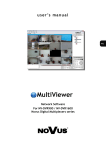
u s e r ’s m a n u a l
instrukcja obsługi
NV-DVR09NET
NV-DVR016NET
u s e r ’s m a n u a l
NV-DVR09NET
NV-DVR016NET
NV-DVR09NET / NV-DVR016NET ver. 1.2 - User’s manual
WARNINGS AND PRECAUTIONS
WARNING!
READ, KEEP AND FOLLOW THESE INSTRUCTIONS. ALL THE SAFETY
AND OPERATING INSTRUCTIONS SHOULD BE READ BEFORE THE
PRODUCT IS OPERATED.
WARNING:
TO REDUCE THE RISK OF FIRE OR ELECTRIC SHOCK, DO NOT EXPOSE THIS UNIT TO
RAIN OR MOISTURE IF THIS UNIT IS DESIGNED FOR INDOOR USE ONLY.
WARNING!
USER IS NOT ALLOWED TO DISASSEMBLY THE CASING THERE ARE NO USERSERVICEABLE PARTS INSIDE THIS UNIT. ONLY AUTHORIZED SERVICE PERSONNEL
MAY OPEN THE UNIT
INSTALLATION AND SERVICING SHOULD ONLY BE DONE BY QUALIFIED SERVICE
PERSONNEL AND CONFORM TO ALL LOCAL CODES
WARNING!
DIGITAL MULTIPLEXER IS ELECTROSTATIC CHARGES SENSITIVE EQUIPMENT
THEREFORE IT SHOULD BE USED IN ACCORDANCE TO OPERATING AND
MAINTENANCE RULES FOR DEVICES BASED ON CMOS/MOSFET TECHNOLOGY.
INFORMATION
This device complies with all requirements included in directives: 89/336/EEC, 93/68/EEC, 72/23/EEC
INFORMATION
Translation is based on original English user’s manual. Data included in following user’s manual is up to date
during the time of printing. Novus Security Sp z o.o. holds exclusive rights to modify this manual. The producer
reserves the rights for device specification modification and change in the design without prior notice.
All rights reserved © NOVUS Security Sp. z o.o.
4
NV-DVR09NET / NV-DVR016NET ver. 1.2 - User’s manual
SAFEGUARDS CONDITIONS
1. Installation and servicing of NV-DVR09NET or NV-DVR016NET should only be carried out by
qualified service personnel and conform to all local codes.
2. Do not place the Multiplexer in areas where ventilation openings might be blocked or covered.
3. There are no user-serviceable parts inside this unit. Only authorized service personnel may open the
unit. The equipment should be protected from mechanical damage and kept clean at all times.
4. Protect this device from being exposed to dust and moisture. In the event of Multiplexer direct
contact with water unplug the device immediately and contact qualified service personnel. Dusty
(soiled/dirty) equipment may be the cause of fire and / or electrical shock.
5. Unplug the unit from the outlet before cleaning. This device can be clean only with a clean damp
cloth. Try to avoid using chemically active liquid cleaners or aerosol. In the event of strong dirt it is
allowed to use gentle cleaning lotion.
6. Power supplier wires as well as signal wires should be fix in the way that there is no risk of
mechanical damage, Please take extra caution not to overload sockets and extension cords to
prevent from the risk of fire.
7. In order to prevent the unit from damage, video channel and signal wires should be equipped with
appropriate surge protection utility conforming to European Union standards. We also advice
utilizing video and data transmission protection.
8. It is not allowed to operate this device in conditions not complying with exploitation requirements
in the range of power supply, air relative humidity or air temperature..
9. Metal objects can be put inside the device. It can cause major malfunction and/or damage the unit.
In the event of situation described above user should contact service immediately for further
assistance.
All rights reserved © NOVUS Security Sp. z o.o.
5
NV-DVR09NET / NV-DVR016NET ver. 1.2 - User’s manual
TABLE OF CONTENTS
1. FOREWORD INFORMATION ...............................................................................................................7
1.1 Main characteristic ..............................................................................................................................7
1.2 NV-DVR09NET and NV-DVR016NET TECHNICAL SPECIFICATION .......................................8
2. DEVICE POWER UP.................................................................................................................................9
2.1 Preparing the equipment for operation. ..............................................................................................9
2.2 Electric connectors of back panel. ....................................................................................................10
2.3 External Devices Connection ...........................................................................................................11
2.4 HDD Installation ..............................................................................................................................12
2.4.1 Swappable bay HDD installation .........................................................................................12
2.4.2 Internal HDD installation (inside the Multiplexer) ...............................................................12
2.5 Device power on and power off. ......................................................................................................13
3. FRONT PANEL DESCRIPTION ...........................................................................................................14
4. DEVICE MENU........................................................................................................................................16
4.1 System ..............................................................................................................................................17
4.2 Cameras ............................................................................................................................................20
4.3 Motion Setup (Motion Detection).......................................................................... ...........................22
4.4 Recording .........................................................................................................................................24
4.5 Alarms ..............................................................................................................................................26
4.6 Event List .........................................................................................................................................28
4.7 HDD Management ...........................................................................................................................29
4.8 Load Default.....................................................................................................................................30
5. RECORD SETUP .....................................................................................................................................31
5.1 Manual Recording ............................................................................................................................31
5.2 Schedule Recording .........................................................................................................................31
6. PLAYBACK ..............................................................................................................................................33
6.1 Time Search .....................................................................................................................................33
6.2 Searching Recorded Data From The Event List ...............................................................................35
7. BACKUP ...................................................................................................................................................36
7.1 External Devices Data Backup .................................................................................................... ....36
7.2 Compact Flash Backup .....................................................................................................................36
7.2.1 Single Image Backup ............................................................................................................37
7.2.2 AVI Backup ..........................................................................................................................37
8. ALARM DEVICES INPUTS AND OUTPUTS CONNECTION .........................................................38
9. SPEED DOME CAMERA - CONNECTION AND CONTROL. .........................................................40
9.1 Novus Speed Dome Camera Connection ..........................................................................................40
9.2 Camera Control .................................................................................................................................42
10. NETWORK FUNCTION .......................................................................................................................43
10.1 Computer Hardware Requirements ...............................................................................................43
10.2 Network Settings Configuration .....................................................................................................44
10.3 Initiating Connection .......................................................................................................................45
10.4 User Interface View.........................................................................................................................46
10.5 User Interface Function Description................................................................................................46
10.5.1 Display Settings ...................................................................................................................46
10.5.2 Transmission Speed .............................................................................................................47
10.5.3 Saving images on PC ..........................................................................................................48
10.5.4 Network Applet Configuration .............................................................................................50
10.5.4.1 Multiplexer Logs - system registry ........................................................................50
10.5.4.2 System Settings .....................................................................................................50
10.5.4.3 User Accounts Management..................................................................................51
10.5.4.4 Network Connection Parameters ..........................................................................51
10.5.4.5 Alarm Event Notification ......................................................................................52
10.5.6 Multiplexer Remote Control ......................................................................................................53
ATTACHMENTS—HDD CAPACITY TABLE ........................................................................................54
All rights reserved © NOVUS Security Sp. z o.o.
6
NV-DVR09NET / NV-DVR016NET ver. 1.2 - User’s manual
FOREWORD INFORMATION
1.
FOREWORD INFORMATION
Digital Multiplexer NV-DVR09NET / NV-DVR016NET was design specifically to work in CCTV
surveillance systems. This devices incorporates the advantages of digital image recording with the
simplicity installation and operation of time lapse recorders. This device utilizes very effective
compression method, ensuring high quality, detailed images. This device also provides function of
recording one audio channel, furthermore improving overall rating of this equipment and at the same
time meeting with all modern surveillance systems requirements.
1.1 Main characteristic.
User friendly interface, with functions known from analog multiplexers;
The simplicity and convenience of using HDD instead of video tapes;
Immediate access to stored material;
Menu access protected by password;
The possibility of remote control and viewing the images using the Ethernet (protocol TCP/IP);
Wavelet compression algorithm with various image quality settings;
Schedule recording with selection of mode and recording speed;
The possibility of installing two HDD 3.5’’ IDE, one of them placed in swappable bay;
Simultaneous real time display of all channels;
Adjustable recording speed, up to 50 fields per second (PAL);
Alarm recording function;
Motion detection function with definable active areas;
Copping the files feature (JPG, AVI format) to Compact Flash memory card or utilizing network;
One audio channel real time recording;
PTZ cameras control (using front panel buttons or through computer network);
All rights reserved © NOVUS Security Sp. z o.o.
7
NV-DVR09NET / NV-DVR016NET ver. 1.2 - User’s manual
NV-DVR09NET and NV-DVR016NET TECHNICAL SPECIFICATION
1.2. NV-DVR09NET and NV-DVR016NET TECHNICAL SPECIFICATION
Video Input:
16 (NV-DVR016NET) or 9 (NV-DVR09NET)
Video inputs (BNC), 1Vp-p/75 Ω;
Video Output:
1 Output (BNC), 1Vp-p/75 Ω to Main monitor;
1 Output S-Video to Main monitor;
1 Output (BNC), 1Vp-p/75 Ω to Spot monitor;
Video Compression:
Wavelet;
Resolution:
720 x 288 (recording), 720x576 (displaying);
Recording modes:
Continuous/Manual/Time-lapse/Alarm/Motion detection;
Recording speed:
Up to 50 fields / sec. (PAL);
Playback speed:
Up to 50 fields / sec. (PAL);
Searching modes:
Time / Date / Event ;
Display modes:
NV-DVR016NET: Full screen; Split screen: 4,9,13,16 cameras on the monitor;
NV-DVR09NET: Full screen; Split screen: 4, 8, 9 cameras on the monitor;
Video loss detection:
Yes;
Ethernet:
Integrated network card (RJ 45);
Event list:
Yes;
HDD:
The possibility of installing two HDD 3.5’’ IDE, one of them placed in
swappable bay;
Compact Flash:
Integrated slot for memory card connection (CF type I and II)
Relay Output:
1 relay output (alarm);
Menu Setting:
On Screen Display;
User Interface:
Multilevel menu in English language;
Clock:
Built in Real Time Clock (RTC);
Watchdog function:
Yes;
RS-232 communication port:
9-pin socket D-Sub;
RS-485 communication port:
9-pin socket D-Sub;
Audio Input/Output:
1 audio channel input (monophony1);
Dimensions:
430 (wide) x 88 (height) x 380 (length) mm;
Power Supply:
100 ~ 240 V AC ;
Operating Temperature:
0°C~ +40°C;
All rights reserved © NOVUS Security Sp. z o.o.
8
NV-DVR09NET / NV-DVR016NET ver. 1.2 - User’s manual
DEVICE POWER UP
2. DEVICE POWER UP
2.1 Preparing the equipment for operation.
Please take an extra caution when unpacking the device.
Please ensure that following items are included in the package:
Digital Multiplexer
NV-DVR09NET or NV-016NET
Net cross cable for Multiplexer-PC
connection
CD-ROM containing necessary
Software and Manuals
HDD Swappable Bay lock-keys
Power Supply cord
u se r ’s ma n u a l
NV-DVR09NET
NV-DVR016NET
Alarm Terminal Connector
User’s Manual
If the equipment has been damaged during transport, the contents of package should be packed back to
the original box. Contact with the supplier for further assistance.
WARNING !
It is not allowed to power on the equipment directly after it has been brought from a place of low
temperature. If the device has been brought from the area of lower temperature the user should
wait until the equipment will slowly warm up and reach the room temperature. The condensation
of moisturized air may cause short circuit and in result damage the device.
All rights reserved © NOVUS Security Sp. z o.o.
9
NV-DVR09NET / NV-DVR016NET ver. 1.2 - User’s manual
DEVICE POWER UP
2.2
Electric connectors of back panel.
1
24
25
2
3
26
4
27
285 296
30
7
31
8
32
9
NV-DVR09NET
33
13
24
1
25
2
36
12 35
11 3410
26
3
27
285 296
4
307
31
8
32
9
34
10
35
11
36
12
NV-DVR016NET
33
13
1.
POWER ~90~260V :
power supply socket and power switch;
2.
3.
4.
Fan:
Audio in:
Audio out :
cooling fan (do not block or cover!);
input for audio recording (socket RCA so called „cinch” );
audio output socket RCA so called „cinch” );
5.
SPOT:
output for connecting Spot monitor (additional); display only in full screen;
6.
BACKUP VIDEO OUT:
output connection for standard video recorder in purpose of data backup;
7.
MONITOR OUT:
output connection for Main monitor; user might select one of various split
screen display option, 1 CSW connector and 1 S-Video socket to connect
additional Main monitor;
8.
ALARM:
9 (16) alarm inputs, 1 alarm relay;
9.
RS-232/485:
9 pin serial port connection RS-232 type D-Sub, for device remote control
(function not active); port RS-485 for PTZ control;
10.
VIDEO OUTPUT:
video output for camera connection;
11.
75Ω / ∞:
video inputs termination switchers;
12.
VIDEO INPUT:
video inputs for camera connection;
13.
Ethernet:
RJ-45 socket for net computer connection;
All rights reserved © NOVUS Security Sp. z o.o.
10
NV-DVR09NET / NV-DVR016NET ver. 1.2 - User’s manual
DEVICE POWER UP
2.3 External Devices Connection
All installation procedures should be made by qualified personnel.
Before device installation and operation please familiarize with the schematics shown below. Depending on
specific user needs and requirements each system will consist of various number of external devices. Monitors,
cameras and other devices are not included and must be purchased separately. Detailed description of devices
connection is included in next chapters of this manual.
Standard Cameras
Main Monitor
(BNC and/or S-Video)
Spot Monitor
(BNC)
Wideo
RS-485
Speed Dome Cameras
External Devices
Connected to Alarm
Inputs
PIR Detectors
Compact Flash memory card
LAN / WAN
External Devices
Connected to Alarm
Relays
E.g. alarm lights, sirens etc..
Reed Relays
PC Computers
for Remote Acces
Alarm
System
Modules
All rights reserved © NOVUS Security Sp. z o.o.
11
NV-DVR09NET / NV-DVR016NET ver. 1.2 - User’s manual
DEVICE POWER UP
2.4 HDD Installation
Two HDD can be installed in NV-DVR016NET and NV-DVR09NET Digital Multiplexers. One of
this disk can be installed inside the device, second might be placed in swappable bay.
WARNING: Producer advices utilizing Hitachi HDD.
Max. allowed capacity of single HDD is 250GB.
Before installing HDD please make sure that jumper are set properly.
In the event of using only one HDD it must be set as MASTER. In the event of two HDD, one of them
must be set in MASTER mode and the second in SLAVE mode. HDD configuration of specified type
and manufacturer is described in the HDD manual supplied with the HDD.
2.4.1 Swappable bay HDD installation
Before installation disconnect power supply cord.
Place properly set HDD in swappable bay and then screw it to the wall utilizing 4 supplied screws..
Place the swappable bay in the Multiplexer and close it with the key, attached in the package.
2.4.2 Internal HDD installation (inside the DVR)
WARNING!
Internal HDD should be installed by qualified service personnel.
The housing of the Multiplexer can be opened only for internal HDD installing according to the
installing procedure described in this manual on page 55.
If the Multiplexer housing is opened in a different purpose the warranty is void.
All rights reserved © NOVUS Security Sp. z o.o.
12
NV-DVR09NET / NV-DVR016NET ver. 1.2 - User’s manual
DEVICE POWER UP
2.5 Device power on and power off.
Before powering on the device please make sure that power supplied (voltage and frequency)
conforms to device requirements. Also make sure that the power switcher is set to „0”, HDD
swappable bay is locked with the key and that the all external devices are connected properly.
WARNING: We do not advice to connect any additional devices (such us cameras, monitors, etc..)
while device operation.
Device power on is activated by switching the power switch to position „1”.
The loading procedure of the operating system takes about 30 seconds.
During this procedure various information will appear on the screen.
During this procedure please do not press any buttons on the front panel of this device.
The loading procedure is finished when camera images will appear on the Main monitor along with
their descriptions and the system time.
To power off the device stop the recording and shut down the device using power switch.
All rights reserved © NOVUS Security Sp. z o.o.
13
NV-DVR09NET / NV-DVR016NET ver. 1.2 - User’s manual
FRONT PANEL DESCRIPTION
3.
FRONT PANEL DESCRIPTION
2
1
8
7
4
5
6
2
1
8
3
7
3
4
6
1.
Split screen buttons;
In programming mode these buttons function as cursors;
In PTZ mode these buttons control the camera movement;
2.
Light Diode informing about the device current status:
POWER - power on status;
REC - recording in progress;
PLAY - playback in progress;
H.D.D. - HDD working;
3.
Channel selection switchers;
4.
Compact Flash memory card socket (CF) for data backup;
5.
HDD swappable bay;
All rights reserved © NOVUS Security Sp. z o.o.
14
5
NV-DVR09NET / NV-DVR016NET ver. 1.2 - User’s manual
FRONT PANEL DESCRIPTION
6.
MENU - button activating on screen display;
ENTER / COPY - in programming mode this button is used to enter sub-menu and edition field;
in playback mode button activates backup procedure on CF card;
AUTO - button activating split screen display on Main monitor;
SEL - split screen display selection button; by pressing this button repeatedly various cameras
will be displayed on the screen in split mode, e.g. in quad mode: (1,2,3,4); (5,6,7,8);
In Full screen mode this button activates function PTZ;
7.
Playback control buttons;
In PTZ mode some of the buttons are used for camera’s zoom control;
8.
Recording ON / OFF buttons;
All rights reserved © NOVUS Security Sp. z o.o.
15
NV-DVR09NET / NV-DVR016NET ver. 1.2 - User’s manual
DEVICE MENU
4.
URUCHOMIENIE URZĄDZENIA
DEVICE MENU
Digital Multiplexer NV-DVR016NET i NV-DVR09NET are equipped with multi level OSD
(on screen display) sub-menus. This menus are used to program settings and execute functions such us
playback or coping. Menu is displayed in English language.
In order to enter device menu press MENU button.
SETUP MENU
SYSTEM
CAMERA
MOTION
RECORD
ALARM
EVENT LIST
HDD MANAGEMENT
LOAD DEFAULT
EXIT
ENTER
SET
EXIT
Main menu consist of 8 sub-menus. The contents of sub-menus is described on following pages of this
manual.
This buttons are used to select the menu items.
Press ENTER button in order to confirm the selection, enter the sub-menu or to enter modified fields.
After entering desired modified field it is highlighted by colored shadow (yellow or blue) .
Pressing buttons modifies the value of selected option.
Exiting the menu accepts and saves inputted modifications. In some extraordinary situations system
requires rebooting. System notifies user before rebooting procedure will take action.
In order to leave selected menu or to return to the higher level menu from individual sub-menus and
modification fields EXIT option should be selected and ENTER button must be pressed. Pressing
MENU button acts similar to the procedures described above. .
All rights reserved © NOVUS Security Sp. z o.o.
16
NV-DVR09NET / NV-DVR016NET ver. 1.2 - User’s manual
DEVICE MENU
4.1 System
SYSTEM SETUP
DATA FORMAT
Y-M-D
DATE Y-M-D
2004/06/10
TIME H: M: S:
10:10:10
AUTO SWITCH DWELL
02 SEC
SPOT SETUP
DATE AND TIME OSD
ENABLE
SYSTEM TYPE
KEYBOARD LOCK
OFF
PASSWORD MODE
DISABLE
EXIT
ENTER
SET
EXIT
Utilizing SYSTEM menu following system settings may be applied:
(1)
DATE :
setting current date;
(2)
TIME :
setting current time;
(3)
DATE FORMAT :
selection of one of three types of date display,
Y– year, M– month, D– day;
(4)
AUTO SWITCH DWELL:
individual cameras display time in sequence on main monitor, time
described in seconds;
By pressing buttons position in sub-menu is selected. Selected sub-menu position is highlighted
by blue shadow.
By pressing buttons the value of selected option is modified.
Pressing ENTER button activates lower level sub-menu.
Pressing MENU button or selecting position EXIT leaves sub-menu.
All rights reserved © NOVUS Security Sp. z o.o.
17
NV-DVR09NET / NV-DVR016NET ver. 1.2 - User’s manual
DEVICE MENU
(5)
SPOT SETUP:
when this option is selected press ENTER, sub-menu will appear on
the screen concerning display options on Spot monitor.
SPOT SETUP
SPOT SWITCHING ON
CAM01
CAM02
CAM03
CAM04
CAM05
CAM06
CAM07
CAM08
02SEC
02SEC
02SEC
02SEC
02SEC
02SEC
02SEC
02SEC
EXIT
ENTER
SET
CAM09
CAM10
CAM11
CAM12
CAM13
CAM14
CAM15
CAM16
02SEC
02SEC
02SEC
02SEC
02SEC
02SEC
02SEC
02SEC
EXIT
Spot switching feature is used to select whether images will be displayed on Spot monitor (ON) or not
(OFF).
If this function is active additional menu lines will appear allowing to set individual dwell time settings
for each specific camera in the system.
WARNING: If the Spot switching option is active for Spot monitor, images currently displayed on
Spot monitor may become a little “brighter” on Main monitor. For this reason we advice to setting
Spot switching option to OFF if the video output for Spot monitor is not currently in use.
(6)
(7)
DATE/TIME DISPLAY: Selecting YES option will display on Main monitor current system
date and time information.
Selecting NO turns off date/time display;
VIDEO SYSTEM: Video system selection;
All rights reserved © NOVUS Security Sp. z o.o.
18
NV-DVR09NET / NV-DVR016NET ver. 1.2 - User’s manual
DEVICE MENU
(8)
KEYBOARD LOCK: This function selects the way in which access to DVR is protected. Along
with system password function it limits the access for selected DVR
functions;
Selecting TYPE 1 option, will lock recording and playback front panel
buttons when user exits the menu;
Selecting TYPE 2 option will lock all of the front panel buttons except
for MENU button;
Selecting OFF option will deactivate button lock option;
(9)
PASSWORD MODE:
When ACTIVE option is selected, system will ask for access
confirmation each time user will try to enter the device menu.
Additional menu line will be displayed;
PASSWORD: 4 digits access password;
WARNING: Please remember to store the access password in a safe
place. If system password is lost service help is required;
All rights reserved © NOVUS Security Sp. z o.o.
19
NV-DVR09NET / NV-DVR016NET ver. 1.2 - User’s manual
DEVICE MENU
4.2 Cameras
CAMERA SETUP
CAMERA
DISPLAY
RECORD
BRIGHTNESS
CONTRAST
HUE
COLOR
CAMERA TITLE
EXIT
ENTER
SET
CAM 01
ON
ON
50
50
50
50
01
EXIT
In CAMERA SETUP menu following settings for each video channel can be set:
(1)
CAMERA : This option is used to select specific channel number for the camera, of which
settings should be displayed or modified;
(2)
DISPLAY: If this option is set to OFF the image from specified camera will not be displayed on
Main monitor in live display mode. In window of specific channel blue shadow will
be displayed instead. On Spot monitor given channel will still be displayed. During
playback hidden channel will be visible. Recording of hidden channel is still active.
To display image from selected camera set this option to ON;
(3)
RECORD: If this option is set to OFF the image from selected camera will not be recorded
however it still will be displayed on the screen. In order to record image from
selected camera set this option to ON;
It is possible to quickly recognize individual settings for each camera by the
color of camera name. If user starts recording and the camera name is displayed in
red color, this means that image from given camera is recorded. If the camera name
is displayed in white color, it means that image from this specific camera is not
currently recorded;
By pressing buttons position in sub-menu is selected. Selected sub-menu position is highlighted
by blue shadow.
By pressing buttons the value of selected option is modified.
Pressing ENTER button activates lower level sub-menu.
Pressing MENU button or selecting position EXIT leaves sub-menu.
All rights reserved © NOVUS Security Sp. z o.o.
20
NV-DVR09NET / NV-DVR016NET ver. 1.2 - User’s manual
DEVICE MENU
(4)
BRIGHTNESS
CONTRAST
HUE
COLOR:
(5)
This menu options allow to adjust the parameters of displayed image to user
individual needs and requirements. The default value is 50;
CAMERA TITLE: This menu option allows user to define each channel name, which will be
displayed on the screen. The specific camera name should provide the
operator with simple and useful information for faster and easier
orientation in monitored area. Each camera name may consist
maximum of six characters.
Camera name displayed by default is camera channel number 01,02 etc;
All rights reserved © NOVUS Security Sp. z o.o.
21
NV-DVR09NET / NV-DVR016NET ver. 1.2 - User’s manual
DEVICE MENU
4.3 Motion Setup (Motion Detection)
MOTION SETUP
CAMERA
CAM01
MOTION DETECTION ON
BUZZER
ON
SENSITIVITY
070
AREA SETUP
EXIT
ENTER
SET
EXIT
In menu MOTION SETUP following settings for each video channel can be set:
(1)
(2)
CAMERA:
In this menu option channel number is selected, in order to display or change the
related parameters;
MOTION DETECTION: If this option is set to ON the system will analyze the activity in image
contents from selected camera. When motion is detected the
Multiplexer will switch to alarm mode. The camera name is displayed
in yellow color when recording in alarm mode.;
If this option is set to OFF motion detection will not be analyzed on
selected channel, and additional menu lines concerning motion
detection will not be displayed;
(3)
BUZZER: If this option is set to OFF then when motion is detected and the system will
switch to alarm mode, sound system will be activated;
(4)
SENSITIVITY: This option allows to define the sensitivity of motion detection. Using this
option allows to evade unnecessary false alarms caused for example by
moving leafs etc.. The bigger the value of this option the more sensitive the
motion detection is. This option can be adjusted in the range from 1 to 100;
By pressing buttons position in sub-menu is selected. Selected sub-menu position is highlighted
by blue shadow.
By pressing buttons the value of selected option is modified.
Pressing ENTER button activates lower level sub-menu.
Pressing MENU button or selecting position EXIT leaves sub-menu.
All rights reserved © NOVUS Security Sp. z o.o.
22
NV-DVR09NET / NV-DVR016NET ver. 1.2 - User’s manual
DEVICE MENU
(5)
AREA SETUP : When this option is selected and ENTER button is pressed a special grid will
appear on the screen with 6x8 fields allowing to define which areas will be
analyzed for motion activity;
Areas in which activity is analyzed are marked with green letter M on grey shadow. To move around
the grid specific sections cursor buttons should be used. Individual section status change is applied by
pressing ENTER button.
When motion is detected on any active channel, Multiplexer will switch to alarm recording mode.
In this mode recording process will confirm to all settings preset in menu RECORD in sub-menu
ALARM RECORD. The camera name will switch it’s color to yellow, and the camera image will be
displayed in the full screen mode. Additionally user may preset in menu settings sound signal
notification. There is also option in ALARM menu allowing to add each motion detection event to the
event list.
Detection function also works if recording is not activated. In that case alarm recording will not be
activated however other actions described above will take place (depending on individual settings).
All rights reserved © NOVUS Security Sp. z o.o.
23
NV-DVR09NET / NV-DVR016NET ver. 1.2 - User’s manual
DEVICE MENU
4.4 Record Setup
RECORD SETUP
NORMAL RECORD FPS
ALARM RECORD FPS
ALARM RECORD DWELL
RECORD QUALITY
AUDIO RECORD
SCHEDULE RECORD
EXIT
ENTER
SET
50P
50P
10 SEC
HIGH
ON
ON
EXIT
In RECORD SETUP menu following settings can be adjusted:
(1)
NORMAL RECORD FPS:
This option is used to set recording speed for normal and
schedule recording. Speed values are expressed in fields per
second rate. Following values are available: 50, 25, 12, 5, 1,
0,5, 0,2 and 0. Recording speed applies to entire Multiplexer.
Depending on number of recording cameras the Multiplexer
resources are equally divided between each camera. If only
one camera is recording in the system we do not advice
setting recording speed to 50 fields;
(2)
ALARM RECORD FPS:
This option is used to set recording speed during alarm mode
(input alarms and motion detection). The speed values are
expressed in fields per second. Following values are
available: 50, 25, 12, 5, 1, 0,5, 0,2 i 0 . Recording speed
applies to entire device. Depending on number of recording
cameras the Multiplexer resources are equally divided
between each camera. If only one camera is recording
in the system we do not advice setting recording speed to 50
fields;
(3)
ALARM RECORD DWELL:
Time defined in seconds describing the alarm duration.
This setting allows to record in alarm mode for longer
periods of time then the duration of alarm event;
By pressing buttons position in sub-menu is selected. Selected sub-menu position is highlighted
by blue shadow.
By pressing buttons the value of selected option is modified.
Pressing ENTER button activates lower level sub-menu.
Pressing MENU button or selecting position EXIT leaves sub-menu.
All rights reserved © NOVUS Security Sp. z o.o.
24
NV-DVR09NET / NV-DVR016NET ver. 1.2 - User’s manual
DEVICE MENU
(4)
RECORD QUALITY:
This option defines the recording image compression level along with
the recording quality level.
4 quality levels are available: LOW, MEDIUM, HIGH,
HIGHEST. The total duration of recording time for specific
HDD depends on recording quality settings. Information concerning
recording duration availability is listed in ATTACHMENTS RECORDING TIME on page 54;
(5)
AUDIO RECORD:
This option must be set to ON if you wish to record audio channel
Warning: due to large recording distortions we do not advice
recording audio with recording speeds lower then 5F;
(6)
SCHEDULE RECORD: This option allows to set different recording modes in various time
intervals. Set this option to ON to activate schedule recording. Press
ENTER button in order to enter schedule sub-menu. Detailed
description of specific schedule settings can be found in chapter 5.
SCHEDULE RECORD
OAXOAAOOOOOOOOOOOXXOOAA
0
3
6
9
12
15
18
21
24
O: FULL REC
A: ALARM REC
X: NO REC
ENTER
SET
EXIT
All rights reserved © NOVUS Security Sp. z o.o.
25
NV-DVR09NET / NV-DVR016NET ver. 1.2 - User’s manual
DEVICE MENU
4.5 Alarm
ALARM SETUP
BUZZER
BUZZER/ALARM DWELL
VIDEO LOSS ALARM
AUDIBLE ALARM
EXT. ALARM MODE
ALARM DISPLAY MODE
MOTION EVENT
RELAY
EXT.ALARM RELAY
VIDEO LOSS RELAY
MOTION RELAY
EXIT
ENTER
SET
05S
ON
ON
LOW
DISABLE
OFF
ON
ON
ON
EXIT
The ALARM SETUP menu is used to define following alarm options:
(1)
BUZZER/ALARM DWELL: This option is used to preset the sound alarm time duration in the
event of alarm detection. User can preset the system to deactivate
sound alarm after short time duration, shorter then the system
alarm duration;
(2)
VIDEO LOSS ALARM : If this option is set to ON sound alarm will go off each time video
signal loss is detected;
(3)
AUDIBLE ALARM: This option must be set to ON in order to allow the system to activate the
sound alarm;
If this option is set to OFF sound alarm will not be activated;
(4)
EXT.ALARM MODE: This option is used to adjust alarm inputs working conditions
depending on the type of external devices used in the system. If this
option is set to LOW then system status change from lower to higher
state will be treated as alarm event. If this option is set to HIGH then
system status change from higher to lower state will be treated as alarm
event;
By pressing buttons position in sub-menu is selected. Selected sub-menu position is highlighted
by blue shadow.
By pressing buttons the value of selected option is modified.
Pressing ENTER button activates lower level sub-menu.
Pressing MENU button or selecting position EXIT leaves sub-menu.
All rights reserved © NOVUS Security Sp. z o.o.
26
NV-DVR09NET / NV-DVR016NET ver. 1.2 - User’s manual
DEVICE MENU
(5)
ALARM DISPLAY MODE : This option is used to activate displaying related cameras on
a Spot monitor when external alarm or motion detection will be
activated (ENABLE). In such a case normal switching mode will
be postponed for a alarm duration.
If option DISABLE is selected alarm actions will have no impact
on a Spot monitor displaying;
(6)
MOTION EVENT: If this option is set to ON all motion detection events will be stored in the
system registry. If this option is set to OFF motion detection will be
activated and DVR will switch to alarm mode however motion detection
event will no be stored in the system registry;
(7)
EXT.ALARM RELAY: If this option is set to ON the alarm relays will be set as active in the
event of alarm detection on any of alarm inputs;
(8)
VIDEO LOSS RELAY: If this option is set to ON then in the event of video loss detection
alarm relay will be activated;
(9)
MOTION RELAY: If this option is set to ON then in the event of motion detection alarm relay
will be activated.;
All rights reserved © NOVUS Security Sp. z o.o.
27
NV-DVR09NET / NV-DVR016NET ver. 1.2 - User’s manual
DEVICE MENU
4.6 Event List
EVENT LIST
PAGE 1
NR YY / MM /DD HH:MM:SS CAM
01 2004 / 06 / 12
12: 22: 36 01
02 2004 / 06 / 12
14: 22: 36 01
03 2004 / 06 / 12
14: 22: 36 --
ENTER
SET
EVENT
DET
SIG
REC
EXIT
When EVENT LIST is entered system history is available. The system registry stores events recorded
from the time of the last HDD formatting. The events are divided by the time of occurrence. Newest
events are displayed as first. In the case when there are more events then can fit on one page additional
events are displayed on following system registry pages.
Information is divided in columns;
In first column is event number, in the second event date, in the third event time, in the fourth the event
camera number, (-- this sign means that selected event concerns entire system).
In the fifth column specific shortcut describing event type is placed:
−
−
−
−
−
MOT motion detection activation
LOS video signal loss
REC recording initiation
EXT alarm on the alarm input
PWR system reboot due to power failure
By pressing buttons position in system registry is selected. Selected position is highlighted by
blue shadow.
Pressing buttons changes the system registry pages.
Pressing ENTER button activates selected data playback..
Pressing MENU button exits the registry.
All rights reserved © NOVUS Security Sp. z o.o.
28
NV-DVR09NET / NV-DVR016NET ver. 1.2 - User’s manual
DEVICE MENU
4.7 HDD Management
HDD MANAGEMENT
OVERWRITE MODE OFF
CAPACITY WARNING 20 %
HDD FORMAT SETUP
EXIT
DISK
A
B
CAPACITY
250GB
NONE
ENTER
SET
LEFT RATIO
100%
NONE
EXIT
The HDD MANAGEMENT menu is used to define following HDD settings:
(1)
(2)
OVERWRITE MODE: This option is used to select recording mode on HDD. If this option is
set to ON the recording process will be „repeated” meaning that if all
HDD capacity reserved for recording has been already used the system
will start to overwrite data previously stored on that HDD staring from
the point of the oldest recording. Previously stored data will be lost;
If this option is set to OFF the system will stop the recording
process when all available HDD capacity will be used. “Disk Full”
system notification will appear on the screen in the event of low HDD
capacity left for recording;
CAPACITY WARNING: This option defines when the “Disk Full” system notification should
appear on the screen. This setting is expressed in percentage. In the
example shown above the information will be displayed on the screen
when disk free space will drop to 20%. If overwriting option is active
this menu line does not appear in the menu list;
By pressing buttons position in sub-menu is selected. Selected sub-menu position is highlighted by blue shadow.
By pressing buttons the value of selected option is modified.
Pressing ENTER button activates lower level sub-menu.
Pressing MENU button or selecting position EXIT leaves sub-menu.
All rights reserved © NOVUS Security Sp. z o.o.
29
NV-DVR09NET / NV-DVR016NET ver. 1.2 - User’s manual
DEVICE MENU
(3)
HDD Format Setup: To enter disk formatting sub-menu this option should be selected and
ENTER button should be pressed.
HDD Format Setup
HDD PASSWORD PROTECT
HDD PASSWORD
FORMAT
EXIT
ENTER
SET
ENABLE
1111
EXIT
(1) HDD PASSWORD PROTECT: This option is used to set if the disk formatting function
should be protected (ENABLE) by 4 digit password or
not (DISABLE);
(2) HDD PASSWORD: This option is used to set 4 digit password, which will be required in
order to access disk formatting function;
(3) FORMAT: When this option is selected and ENTER button is pressed all data from all
connected HDD will be erased. When option FORMAT is selected the system will
ask for HDD formatting confirmation so the user can reconsider, cancel this option
and exit this menu;
WARNING: Please use the FORMAT option consciously and considerably.
If HDD are formatted all data is lost permanently.
Additionally in the HDD MANAGEMENT menu HDD’s capacity and available free space information
is displayed.
Disk A is a MASTER disk, disk B is a SLAVE disk.
If specific HDD is not installed in the system information NONE is displayed.
4.8 Load Default
When this option is selected factory default system settings will be set.
However Schedule settings are not erased.
All rights reserved © NOVUS Security Sp. z o.o.
30
NV-DVR09NET / NV-DVR016NET ver. 1.2 - User’s manual
RECORD SETUP
5. RECORD SETUP
Digital Multiplexer NV-DVR09NET and NV-DVR016NET provide user with manual recording option
(red button, sign ) or according to schedule recording function. Only images from cameras for which
recording option is set to active will be recorded in both of recording modes (chapter 4.2). Camera
names which recording function is set to active will appear in red color during recording.
5.1 Manual Recording
When the recording button is pressed Multiplexer will start to record the images from camera
channels connected and activated in the system. During recording process red REC sign appears in the
upper left corner. The continuous recording process will run accordingly to recording speed preset in
RECORD menu in option NORMAL RECORD FPS, in the event of alarm (motion detection and
alarms on alarm inputs) the recording speed will be set accordingly to the speed preset in option
ALARM RECORD FPS.
Sign in the upper right corner identifies the current recording speed. The recording speed is expressed
in (pictures) fields per seconds e.g.. 25FPS. This information is precede by a percentage number of
HDD capacity.
To stop the recording press the REC button again.
5.2 Schedule Recording
NV-DVR09NET and NV-DVR016NET provide schedule function allowing to activate recording
process automatically in desired time of the day.
WARNING: To activate schedule recording in the RECORD menu SCHEDULE RECORD option
must be set to ON.
To enter sub-menu of schedule option button ENTER must be pressed. Menu will appear on the screen
representing various recording modes in different time of the day. Schedule recording can be set
accurate to one hour. It is possible to set only one schedule recording that will be valid each and every
day. Letters represent recording modes valid for given hour.
O-
this option is used to set the continuous recording speed accordingly to values set in
RECORD menu in option NORMAL RECORD FPS , and in alarm recording mode (motion
detection and external alarms) with speed set in ALARM RECORD FPS menu.
A -
this means that recording process will occur only in the event of alarm (motion detection and
external alarms) with speed set in RECORD in option ALARM RECORD FPS
X -
this means that during specified hour the recording process will not occur.
All rights reserved © NOVUS Security Sp. z o.o.
31
NV-DVR09NET / NV-DVR016NET ver. 1.2 - User’s manual
RECORD SETUP
Time line indicators are placed below the letters line. In the example below continuous recording will
be run during following time 0-1; 3-4; 6-18 i 20-22. During this time 1-2; 4-6 i 22-0 only alarm
recording will take effect (external alarms and motion detection)
SCHEDULE RECORD
OAXOAAOOOOOOOOOOOXXOOAA
0
3
6
9
12
15
18
21
24
O: FULL REC
A: ALARM REC
X: NO REC
ENTER
SET
EXIT
In the event of continuous recording (O) displayed information are identical just like in manual
recording (sign REC, speed). Recording in this mode can not be deactivated by recording button. If
someone will try to stop recording using recording button information priority recording will be
displayed on monitor.
SCHEDULE RECORDING...
During alarm recording (A) in the upper left corner symbol |A| will be displayed.
During alarm recording user can manually activate and deactivate continuous recording .
In the event of deactivated recording (X) in the upper left corner symbol |X| will be displayed.
During this recording mode user can activate/deactivate recording manually.
All rights reserved © NOVUS Security Sp. z o.o.
32
NV-DVR09NET / NV-DVR016NET ver. 1.2 - User’s manual
PLAYBACK
6. PLAYBACK (DATA SEARCH)
Digital Multiplexer NV-DVR09NET and NV-DVR016NET allow to find desired recordings in two
ways. First search option is done by inputting specified time and date. Second search option is possible
by viewing the event registry and playback of recordings related selected event. This devices are
capable of working in duplex mode what allows simultaneous playback and recording.
QUICK TIME SEARCH
PLAY TIME SEARCH
EVENT LIST SEARCH
ENTER
SET
STOP
EXIT
6.1 Time Search
When this option is selected date and time menu will appear on the screen allowing to playback
specified data. Additionally the oldest available recording information will appear on the bottom of the
screen.
PLAY TIME SEARCH
YYYY/MM/DD
HH:MM:SS
2004 / 12 / 23
15 : 12 : 23
START TIME:
2004 / 12 / 20
ENTER
SET
14 : 11 : 03
STOP
EXIT
Date and time is selected using arrows . Selection of individual fields (year, month, etc.) is done by
arrows . Selected field changes its color to yellow.
All rights reserved © NOVUS Security Sp. z o.o.
33
NV-DVR09NET / NV-DVR016NET ver. 1.2 - User’s manual
PLAYBACK
When ENTER button is pressed playback will begin.
WARNING: When HDD’s of large capacity are installed in the system the process of data loading
may take few seconds. During that time on the bottom of the screen sign SERCHING will be
displayed.
The playback starts automatically in 9 or 16 images split screen mode (depending on device
version).
During playback user can change the display mode using these buttons:
User can also use numeric buttons as well.
During playback following buttons are active
- standard playback „forward”, pressing this button repeatedly during playback allow to
change the playback speed x1/2, x1/4, x1/1 of nominal speed.
- reverse playback, pressing this button repeatedly during playback allow to change the
playback speed x1/2, x1/4, x1/1 of nominal speed.
- changes forward playback speed, pressing this button repeatedly during playback allow
to change the playback speed x2, x4, x6, x8 of nominal speed.
- changes reverse playback speed, pressing this button repeatedly during playback allow
to change the playback speed x2, x4, x6, x8 of nominal speed
Warning: During accelerated playback (fast forward) with speeds faster then x2, and with
simultaneous recording mode active the playback might not work smoothly.
- pause button, when pressed first time playback is stopped and freeze image is displayed,
when this button is pressed again it allows to view images forward in „frame by frame”
mode; function active only in full screen playback mode
- pause button, when pressed first time playback is stopped and freeze image is displayed,
when this button is pressed again it allows to view images in reverse in „frame by frame”
mode; function active only in full screen playback mode
- stops playback and exit to menu of data selection
All rights reserved © NOVUS Security Sp. z o.o.
34
NV-DVR09NET / NV-DVR016NET ver. 1.2 - User’s manual
PLAYBACK
6.2 Searching Recorded Data From The Event List.
This way of data searching is similar to the viewing through the event list directly from Multiplexer
menu (view chapter 4.6 for more details). The difference between these searching methods is that in
this case we can specify desired time span from which events will be listed.
When EVENT LIST SEARCHING option is selected date and time menu will appear on the screen
that will allow to specify the exact desired time span of which events should be displayed. If e.g.
2004/10/12 is selected then displayed events will include all of the events that have occurred until the
12 October year 2004.
EVENT LIST SEARCH
YYYY/MM/DD
INPUT DATE: 2004 / 12 / 20
ENTER
SET
STOP
EXIT
WARNING: When HDD’s of large capacity are installed in the system the process of data loading
may take few seconds. During that time on the bottom of the screen sign SEARCHING
will be displayed.
.
When event list is displayed use up and down arrow buttons to select following events. To switch
between the event list pages press these buttons .
When ENTER button is pressed data playback will begin.
During playback all buttons described on previous page are active.
All rights reserved © NOVUS Security Sp. z o.o.
35
NV-DVR09NET / NV-DVR016NET ver. 1.2 - User’s manual
BACKUP
7. BACKUP
Digital Multiplexer NV-DVR09NET and NV-DVR016NET allow to backup data in two ways. First
method is copping to additional device e.g. standard video recorder. Second method is to copy data to
Compact Flash memory card, which later can be viewed on PC equipped with appropriate card reader.
Memory card with capacity of 128MB can store from 16 to 25 minutes of video or from 2000 to 3100
single images. The quantity depends on quality in which data was recorded. For memory card of
capacity 256MB the above values should be doubled.
7.1 External Devices Data Backup
Digital Multiplexer NV-DVR09NET and NV-DVR016NET are equipped with output allowing to
connect external storing device. It can be e.g. standard video recorder or computer equipped with
capture card. Device is connected to output marked BACKUP VIDEO OUT.
Signal to this output is send only when playback is activated. In order to backup the data playback on
Multiplexer must be activated and in external device recording process must be run. During backup
process user can change the displayed modes and speeds. However it is important to remember that the
backup device will store the data exactly in the way as the images appear on the Main monitor.
7.2 Compact Flash Backup
Digital Multiplexer NV-DVR09NET and NV-DVR016NET are equipped with interface allowing to
connect Compact Flash memory cards. The memory card input socket is placed on the front panel next
to HDD bay.
Warning: During backup process computer network connection is prohibited. It is advised to
disconnect the device physically from the net for the duration of backup process if
there is a risk of incoming net connection.
The manufacturer advises utilizing only San Disk memory cards of 128 or 256 MB capacity.
The memory card should be input with caution to prevent the memory card socket from being
damaged. The memory card should be input only in one way - the sticker with company logo and
capacity should be faced left.
All rights reserved © NOVUS Security Sp. z o.o.
36
NV-DVR09NET / NV-DVR016NET ver. 1.2 - User’s manual
BACKUP
7.2.1 Single Image Backup
Insert the memory card inside card slot before starting the backup process.
If memory card is inserted into device in the lower left corner sign CF is displayed.
To backup single image in JPEG file, the playback of desired data must be run then selected camera
must be displayed in full screen mode and finally the image must be freeze (pause button) in desired
place. Using and buttons allows to select exact desired images. When desired image is selected
press COPY button. After short time message SAVE OK will appear. Additionally on the bottom of the
screen memory card capacity information will appear. For example information CF Card USED/
CAPACITY: 01M / 126M means that currently 1MB is used from the total available of 126MB.When
the backup process is completed user can select next image or finish backup simply by taking out the
memory card (message CF CARD REMOVED will appear on the screen)
7.2.2 AVI Backup
Insert the memory card inside card slot before starting the backup process.
If memory card is inserted into device in the lower left corner sign CF is displayed.
To backup video sequence in AVI format playback of desired data must be run then selected camera
must be displayed in full screen mode and finally select desired backup time the press button COPY.
After short time message BACKUP TO CF CARD AVI FILE will appear. Additionally on the bottom
of the screen below CF sign AVI sign will appear. This means that backup process is currently running.
During this backup process user may increase or decrease the playback speed.
To finish backup of selected data button COPY should be pressed again. The following message will
appear on the screen:
PROCESSING,
PLEASE WAIT.....
During the backup process the memory card must remain in the memory card reader at all times.
Similar information appears automatically after each minute of backup.
In order to take out the memory card below information must appear on the screen.
SAVE OK
When the backup process is completed user can select next video sequence or finish backup simply by
taking out the memory card (message CF CARD REMOVED will appear on the screen)
Warning: When video sequence that user wants to backup is longer then one minute the device will
automatically divide the backup data into files of duration time of 1 minute (size 2-3 MB).
All rights reserved © NOVUS Security Sp. z o.o.
37
NV-DVR09NET / NV-DVR016NET ver. 1.2 - User’s manual
ALARM DEVICES INPUTS AND OUTPUTS CONNECTION
ODTWARZANIE
8. ALARM AND OUTPUTS CONNECTION
Digital Multiplexer NV-DVR09NET and NV-DVR016NET are equipped accordingly into 9 and 16
alarm inputs which allow to connect external devices.
If external alarm function is active (chapter 6.5) the alarms will be registered in the event registry even
if recording is turned off.
To automatically switch the device to alarm recording mode manual or schedule recording must be
initiated. Junction for cable connection is equipped with handy, removable clamp junctions terminal.
On this terminal also alarm output is placed. For detail terminal description please view image below.
PIN
FUNCTION
1
ALARM INPUT 1
2
ALARM INPUT 2
3
ALARM INPUT 3
4
ALARM INPUT 4
5
ALARM INPUT 5
6
ALARM INPUT 6
7
ALARM INPUT 7
8
ALARM INPUT 8
9
ALARM INPUT 9
10
ALARM INPUT 10
11
ALARM INPUT 11
12
ALARM INPUT 12
13
ALARM INPUT 13
14
ALARM INPUT 14
15
ALARM INPUT 15
16
ALARM INPUT 16
17
--------
18
--------
19
--------
20
GND
21
GND
22
ALARM RESET
23
ALARM OUTPUT N.C.
24
ALARM OUTPUT COM
25
ALARM OUTPUT N.O.
14
13
25
1
.
All rights reserved © NOVUS Security Sp. z o.o.
38
NV-DVR09NET / NV-DVR016NET ver. 1.2 - User’s manual
ALARM DEVICES INPUTS AND OUTPUTS CONNECTION
Inputs work in TTL standard and for this reason appropriate voltage levels should be provided for each
input circuit like shown on the schedule below. Impulse on Input occurs if low or high logic state is
detected, depending on ALARM menu settings.
external switch
(e.g. reed relay)
1k
Multiplexer
Input 1
1k
ground
GND
External Circuit
Ground
Warning: Alarm Inputs and Outputs are not equipped with surge protection. Appropriate surge
protection devices should be installed to prevent alarm Inputs/Outputs damage.
Digital Multiplexer NV-DVR09NET and NV-DVR016NET are equipped with alarm output.
NC (normal close) and NO (normal open) outputs are available. Maximum current load output can not
exceed 100mA. For example LED diode can be connected directly to output e.g. creating circuit like on
the diagram below. If there is a need to connect devices of high power consumption additional circuits
should be installed e.g. with additional relay.
Multiplexer
LED
R
Vcc
ALARM OUTPUT N.O.
ALARM OUTPUT COM
External Circuit
All rights reserved © NOVUS Security Sp. z o.o.
39
NV-DVR09NET / NV-DVR016NET ver. 1.2 - User’s manual
SPEED DOME CAMERA - CONNECTION AND CONTROL
9. SPEED DOME CAMERA - CONNECTION AND CONTROL
Digital Multiplexer NV-DVR09NET and NV-DVR016NET allow to control up to 9 (16) speed dome
cameras.
For camera control port RS-485 is used. Control lines are connected in a “daisy chain” way. Camera
control is operated by buttons placed on front panel or utilizing net software. For proper operation each
speed dome camera must have individual system address. Following rule should be applied: camera
with address 1 is connected to video input nr 1, camera with address 2 connected to channel 2 and so
on.
Control is done by Pelco-D protocol.
Warning: All cameras in the system should have set identical protocol and transmission speed
9600BPS (please view Speed Dome Camera Manuals).
Camera connection description applies to Novus camera connections. In order to connect cameras of
other producers technical department should be contacted and user should familiarize himself with
specific camera manual.
9.1 Novus Speed Dome Camera Connection
The Speed Dome Camera control lines are connected in a “daisy chain” way with the use of twisted
pair cable (UTP 5th class). The maximum length of line can not exceed 1200m.
The telemetry control signals are lead to junction DB9 with the
1
5
Pin 9 Should be connected with RX + / D+ in the camera
Pin 8 Should be connected with RX - / D – in the camera
6
9
symbol RS232/485.
All rights reserved © NOVUS Security Sp. z o.o.
40
NV-DVR09NET / NV-DVR016NET ver. 1.2 - User’s manual
SPEED DOME CAMERA - CONNECTION AND CONTROL
Novus CAMA I connections
Multiplexer
8
Data
Video
Rx+(Tx+) Rx- (Tx -)
Novus
CAMA I
Rx+(Tx+) Rx- (Tx -)
Novus
CAMA I
All rights reserved © NOVUS Security Sp. z o.o.
41
9
NV-DVR09NET / NV-DVR016NET ver. 1.2 - User’s manual
SPEED DOME CAMERA - CONNECTION AND CONTROL
9.2 Camera Control
To enter camera control mode specific camera should be selected which we wish to operate and set
display to full screen mode and then press SEL button.
In the upper right corner sign PTZ will appear informing that Multiplexer is set to Speed Dome
Camera control mode and that some of buttons are now active as a Speed Dome control buttons.
These buttons allow to move camera in various direction: tilt up & down, pan left & right.
- zoom in
- zoom out
When MENU button is pressed special PTZ menu will appear. Using this menu camera pan and tilt one
of 5 speed levels may be defined. Speed levels are expressed by square symbols.
Scan function is not available in cameras described above.
PTZ SETUP
UP-DOWN SPEED:
LEFT-RIGHT SPEED: AUTO SCAN SPEED: PROTOCOL TYPE: PELCO-D
- SELECTION,
- CHANGE
To exit PTZ menu MENU button should be pressed.
To exit PTZ camera control mode button SEL should be pressed. Sign PTZ will disappear from the
screen and Multiplexer will return to normal working mode (buttons will activate standard functions)
All rights reserved © NOVUS Security Sp. z o.o.
42
NV-DVR09NET / NV-DVR016NET ver. 1.2 - User’s manual
NETWORK CONNECTION FEATURE
10. NETWORK FUNCTION
Digital Multiplexer NV-DVR09NET and NV-DVR016NET provide network connection option
utilizing TCP/IP protocol. It is required to assign static IP address for the devices.
Warning: Operation conducted by net has direct influence on local operation. For example change of
display mode with the use of net will also change the display mode on Main monitor. This should be
kept in mind. Net connection should be limited to the minimum especially if someone is monitoring
area locally on Main monitor. This problem does not occurs in the systems without local operators.
Warning: NOVUS company is not distributor of server systems, routers, hubs, and other net devices
which have influence on proper net working. For configuration propriety of mentioned devices net user
or network administrator is responsible.
10.1 Computer Hardware Requirements
Processor
Intel® Pentium® 1GHz (or higher)
RAM memory
Minimum 128MB
Internet browser
Internet Explorer 5.0 (or higher), with Java script set as active
Other devices required
Graphic Card, AGP x 4, 16MB
Operating System
Microsoft® Windows® 98 / ME / 2000 / XP™
All rights reserved © NOVUS Security Sp. z o.o.
43
NV-DVR09NET / NV-DVR016NET ver. 1.2 - User’s manual
NETWORK CONNECTION FEATURE
10.2 DVR Network Settings Configuration
To configure network settings IPInstaller software should be used. This software is provided on CD
included in the package.
To connect with Multiplexer application IPInstaller.exe, should be run. The device must be connected
with the computer with the use of net cross cable also included in the package. Power on the
Multiplexer. When system boot is finished Search Device button should be clicked.
On the left side in the field Device lists the name of the device will appear along with its current IP
address.
When this position is clicked on the right side net settings will appear:
−
IP Address
−
Netmask
−
Gateway
−
HTTP Port
−
MAC
The above settings can be edited (except MAC) to adjust settings to meet specific net requirements.
When configuration settings is finished save changes clicking on Submit.
Net module reboot information will appear on the screen and after short time modified devices setting
will appear.
Clicking Exit will exit application discarding changes.
All rights reserved © NOVUS Security Sp. z o.o.
44
NV-DVR09NET / NV-DVR016NET ver. 1.2 - User’s manual
NETWORK CONNECTION FEATURE
10.3 Initiating Connection
Microsoft Internet Explorer should be used for net connection. Multiplexer IP address should be input
in the browser address bar ( IP address can be acquired with the use of application IPInstaller.exe).
If selected communication port is different then 80, then after address space, colon and port number
must be input.
Example: for connection like in the example on previous page, following IP address should be input in
the web browser address bar:
192.168.2.128 :100
During connection applet is downloaded from the device. This applet provides all Multiplexer network
functions.
Network interface should appear after a while.
Depending on Windows security settings it might be necessary to accept unknown for system Active X
format (click Yes)
Uwaga: W przypadku
problemów z ładowaniem
się appletu należy sprawdzić
czy w Opcjach
internetowych przeglądarki
w zakładce Ogólne, w
pozycji Tymczasowe pliki
internetowe / Ustawienia
wybrana jest opcja
automatycznego
sprawdzania nowszych
wersji przechowywanych
stron.
Click Yes
All rights reserved © NOVUS Security Sp. z o.o.
45
NV-DVR09NET / NV-DVR016NET ver. 1.2 - User’s manual
NETWORK CONNECTION FEATURE
10.4 User Interface View
Following description applies to network interface version 3.14.
The tabs on the left side of the screen allow to set various configuration and operation settings. Camera
images fill the rest of the screen space. (default split screen to 9 or 16).
10.5 User Interface Function Description
10.5.1 Display Settings
In the tab Image Adjust user can adjust image display settings.
Quality option allows to select one of three levels of display quality: High, Medium, Low. The higher
the quality level settings the lower the displayed images refresh rate.
Resolution option allows to select one of three resolutions: QCIF - 176x144, CIF - 360x288, VGA 640x480. The higher the resolution settings are the lower the displayed images refresh rate is.
Advanced option allows to select one of several image settings to correct the overall image appearance.
Buttons + (increase), - (decrease), STD (restore default settings).
These settings are: Brightness, Contrast, Saturation, Hue, Sharpness.
All rights reserved © NOVUS Security Sp. z o.o.
46
NV-DVR09NET / NV-DVR016NET ver. 1.2 - User’s manual
NETWORK CONNECTION FEATURE
Current refresh rate and resolution is displayed on Status Bar.
To display this Status Bar right-click on camera image and select Status Bar.
Right-clicking on camera images brings on menu that allows to define the video stream display mode
in the web browser window. By default the image is „expanded” to entire available space irrespectively
of real image resolution. Actual size option restores the real image display.
With default settings when the web browser window is decreased only part of camera images is visible.
depending on actual window size (the image size does not change). Resizable option should be checked
if we desire to automatically adjust image size to fit in the window actual size.
10.5.2 Transmission Speed
Operation Mode tab is used to adjust transmission speed to meet user expectations and network
capabilities.
Continuous option allows for continuous transmission with maximum speed and refresh rate .
However this will highly reduce the network capacity (around 4,5Mb/s is required).
If value number in seconds or milliseconds is input and Periodic option is marked the data will be sent
periodically (with interval set in the window). As the refresh rate will drop the network free capacity
will increase significantly.
All rights reserved © NOVUS Security Sp. z o.o.
47
NV-DVR09NET / NV-DVR016NET ver. 1.2 - User’s manual
NETWORK CONNECTION FEATURE
10.5.3 Saving images on PC
Image Capture tab is used to active actual image capturing function of specified numbers of single
images video sequence from the playback/displayed stream. If camera images are displayed in quad
mode or is freeze that’s exactly how it will be saved. The transmission speed and quality of saved files
depends on settings describe on previous pages.
To capture single currently displayed image F12 button should be pressed and save path should be
input/selected or Snapshot option should be selected.
To bring on Image Recording menu Recording option should be selected or press F11 button.
All rights reserved © NOVUS Security Sp. z o.o.
48
NV-DVR09NET / NV-DVR016NET ver. 1.2 - User’s manual
NETWORK CONNECTION FEATURE
In the field Select user must specify if captured images should be single frames (JPEG) or video
sequences (AVI) or both .
- When saving JPEG files in the field JPEG exact number of saved files can be selected.
No Limit option will save all files up to the point of manual stop (F11 button).
Number option allows to specify the number of frames which will be saved.
Size option allows to specify in kilobytes the total size of saved frames.
Time option allows to specify in seconds the capturing time.
The image capturing begins at the moment when Start button is pressed.
The files are stored in the folder selected in the field Save Path. The save path can be selected when
Save As option is clicked.
Pre Name field is used to specify prefix which will be added to each file name.
Apply option is used to save settings.
- When saving AVI files in the field AVI the number of data which will be saved can be selected.
No Limit option will save all files up to the point of manual stop (F11 button).
Number option allows to specify the number of frames in video sequence.
Size option allows to specify in kilobytes the total size of saved video sequnce.
Time option allows to specify in seconds the capturing time.
The field Maximum Number of Frames in Each File allows to specify the number of frames of
which files will consist of. Together with long capture time this allows to divide video sequences into
few smaller files.
The video sequence capturing begins at the moment when Start button is pressed.
The files are stored in the folder selected in the field Save Path. The save path can be selected when
Save As option is clicked.
Pre Name field is used to specify prefix which will be added to each file name.
Apply option is used to save settings.
User is notified of current image capturing status. In the lower right corner yellow sign indicates
capturing JPEG files and red sign indicates capturing AVI files.
All rights reserved © NOVUS Security Sp. z o.o.
49
NV-DVR09NET / NV-DVR016NET ver. 1.2 - User’s manual
NETWORK CONNECTION FEATURE
10.5.4 Network Applet Configuration
Configuration tab is used for advanced applet settings such us user accounts administration, alarm
function, etc.
10.5.4.1 Multiplexer Logs - system registry
View Log option allows to view system registry of the network interface. Multiplexer Logs lists
information of type of the event, user IP and MAC address who made modifications and the exact time
and date of the event.
10.5.4.2 System Settings
System Setting option is used to retrieve following system information and to perform system
modifications:
−
−
−
−
−
−
−
−
−
−
−
Version - network interface version information
DVR Title - device name, to enter new name input desired characters and press Change to save
Device’s time - system time (network interface only)
Time zone - time zone
NTP Server - time synchronization server
Input new time, Synchronize with PC’s time - mark this option and click Adjust to synchronize
system clock with PC clock
Language setting - interface language selection
four channel DVR, nine channel DVR, sixteen channel DVR - model selection with which
connection is initiated (by default applet should detect automatically correct device type)
NTSC System, PAL System - TV system selection in which Multiplexer will work
Reboot DVR - network interface restart
Firmware update - Network interface update (service function)
All rights reserved © NOVUS Security Sp. z o.o.
50
NV-DVR09NET / NV-DVR016NET ver. 1.2 - User’s manual
NETWORK CONNECTION FEATURE
10.5.4.3 User Accounts Management
User Management option is used to acquire following information and apply changes in the user
accounts and network access passwords. There are two types of users.: Administrator and Guest
Administrator has full access to the system, Guest may only watch the displayed image in the display
mode set by administrator or local operator.
−
−
−
−
−
User authorization required: if Yes is selected Set is pressed the system will require authorization
confirmation during network connection
Administrator option allows to change the name and administrator password (default settings is
admin, admin), new user name is input in Username field new password is input in Password
field. Confirm option is used to verify and confirm new settings. Modifications are confirmed by
clicking on Set & Change
Add a user or change password option is used to input new user name and password who will be
added to the list when Set & Change is clicked.
This field is also use to modify current user password when one of the existing users is selected
from the list below.
Delete user - select desired user from the list and click Delete and selected account will be
erased. However admin account can not be erased.
Current user list - the list of currently registered user accounts. From this list accounts can be
selected for modification/deletion
10.5.4.4 Network Connection Parameters
Network Setting option is used to acquire following network settings information and connection
methods:
−
LAN - network settings, Manually - manual settings input (with the use of application IPInstaller),
Automatically by DHCP - automatically set settings by DHCP server (if the network is configured
in this method), in this mode when option On is marked in Send email after DHCP email will be
send each time address is given by server.
DNS Setting - 3 server addresses DNS if they are required for connection
−
−
Port Setting - HTTP port number used for transmission, default port 80, we advice changing the
port address to any desired after consulting with network administrator
To save current settings press Save Setting. To set settings as valid immediately Reboot immediately
option should be marked and Save Setting must be clicked.
PPPoE tab is used to set transmission settings in PPPoE protocol.
WARNING:
In the Network interface version 3.14 the PPPoE protocol and dynamic IP
(Dynamic DNS) operation are inactive.
All rights reserved © NOVUS Security Sp. z o.o.
51
NV-DVR09NET / NV-DVR016NET ver. 1.2 - User’s manual
NETWORK CONNECTION FEATURE
10.5.4.5 Alarm Event Notification
Alarm and Motion Detection - this option is used to apply modification in the FTP server settings
(image sending) and e-mails form alarm events.
−
Mail Setting ( for sending images detected ) - option used to adjust e-mail notification settings:
Mail server - mail server address used for sending e-mails.
Username - the name of the user required when login to mail server (the e-mail account should be
created earlier).
Password - user password required during login to server mail
Sender email - sender e-mail address (used for sending e-mails)
Receiver email - the receiver e-mail address
Subject - notification title (subject title)
Send mail when alarm and motion detected this option must be marked in order to send e-mail
notification.
Save Setting to active the settings this option should be clicked..
−
FTP Setting ( for uploading images detected ) - option used to send alarm images to server FTP
FTP server - image receiving FTP server address
Username - username required while login to FTP server
Password - user password required while login to FTP server
Port - transmission port
Upload path - user path, if program designated root folder is different then default the appropriate
upload user path must be entered
Upload images when alarm and motion detected this option must be marked in order to send alarm
images files
Save Setting to activate and save current settings modification click this option
All rights reserved © NOVUS Security Sp. z o.o.
52
NV-DVR09NET / NV-DVR016NET ver. 1.2 - User’s manual
NETWORK CONNECTION FEATURE
10.5.6 Multiplexer Remote Control
DVR Control Panel tab is used to activate or deactivate remote control interface. When the option DVR
Control Panel is clicked special icon-key bar will be displayed on the bottom of the screen. This bar is
used for remote control.
As we can see above all of the front panel Hard keys are displayed in this bar, except for MENU and
REC buttons. The virtual keys function is identical with the real front panel hard keys described
in previous chapters.
WARNING: If key-lock option is set as active then the virtual network interface keys are lso
deactivated.
All rights reserved © NOVUS Security Sp. z o.o.
53
NV-DVR09NET / NV-DVR016NET ver. 1.2 - User’s manual
ATTACHMENTS – RECORDING TIME TABLE
Approximate recording time (hours) on HDD for various speed and quality settings (given compression
ratio) for PAL standard. To calculate time table for other HDDs just simply use a proportion.
E.g. recording time for 2 HDD 120GB each, will be two times longer then for 120GB HDD.
80
HDD [GB]
FPS
18 (LOW)
8000000000
Quality [kB/s]
23 (MEDIUM)
32 (HIGH)
50
25
12
10
5
1
0,5
25
50
105
126
251
1255
2511
20
40
82
99
198
988
1975
HDD [GB]
120
12000000000
Quality [kB/s]
FPS
18 (LOW)
23 (MEDIUM)
14
28
58
69
139
694
1389
32 (HIGH)
50
25
12
10
5
1
0,5
38
75
157
188
377
1883
3766
30
59
123
148
296
1481
2963
HDD [GB]
160
16000000000
Quality [kB/s]
FPS
18 (LOW)
23 (MEDIUM)
32 (HIGH)
50
100
209
251
502
2511
5022
40
79
165
198
395
1975
3951
HDD [GB]
250
25000000000
Quality [kB/s]
50
25
12
10
5
1
0,5
18 (LOW)
23 (MEDIUM)
78
157
327
392
785
3923
7847
32 (HIGH)
Les then an day
More then a day (24h) , less then a week (168h)
More then a week (168h) , less then a month (720h)
Over a month
All rights reserved © NOVUS Security Sp. z o.o.
54
12
23
49
59
117
586
1172
57 (HIGHEST)
28
56
116
139
278
1389
2778
62
123
257
309
617
3086
6173
8
16
33
39
78
391
781
57 (HIGHEST)
21
42
87
104
208
1042
2083
50
25
12
10
5
1
0,5
FPS
57 (HIGHEST)
16
31
65
78
156
781
1562
57 (HIGHEST)
43
87
181
217
434
2170
4340
24
49
102
122
244
1220
2441
NV-DVR09NET / NV-DVR016NET ver. 1.2 - User’s manual
ATTACHMENTS – INTERNAL HDD INSTALLING PROCEDURE
WARNING! Disconnect power supply cord from the device before HDD installation.
1.
Unscrew 5 screws (marked with the red arrows on the image below) take off the top cover.
2.
View of the device without the top cover.
All rights reserved © NOVUS Security Sp. z o.o.
55
NV-DVR09NET / NV-DVR016NET ver. 1.2 - User’s manual
ATTACHMENTS – INTERNAL HDD INSTALLING PROCEDURE
3.
Draw out the HDD swappable bay....
4.
... and place HDD underneath (previously properly preset with the HDD jumpers)
All rights reserved © NOVUS Security Sp. z o.o.
56
NV-DVR09NET / NV-DVR016NET ver. 1.2 - User’s manual
ATTACHMENTS – INTERNAL HDD INSTALLING PROCEDURE
6.
Match the HDD mounting holes directly with mounting holes of the device then screw on 4
mounting screws.
7.
Mount the housing cover and screw it on using 5 mounting screws.
All rights reserved © NOVUS Security Sp. z o.o.
57
NV-DVR09NET / NV-DVR016NET ver. 1.2 - User’s manual
NOTES
All rights reserved © NOVUS Security Sp. z o.o.
58
NV-DVR09NET / NV-DVR016NET ver. 1.2 - User’s manual
NOTES
All rights reserved © NOVUS Security Sp. z o.o.
59
NOVUS Security Sp. z o.o.
431 Pulawska Str 431,
02-801 Warszawa
Poland
www.novuscctv.com
2005-07-27