1
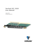
Verilink DIU 2131High-Low Module User Manual September 1999 DATA PORT 2 DATA PORT 1 NEAR END FAR END NEAR END FAR END STAT LOOP LOOP STAT DIU 2131 LOOP LOOP P/N 880-502765-001-D1 Copyright Notice Copyright 1999 Verilink Corporation. All rights reserved. This document does not create any express or implied warranty about Verilink or about its products or services. Verilink’s sole warranty is contained in its product warranty. The end-user documentation is shipped with Verilink’s products and constitutes the sole specifications referred to in the product warranty. Verilink has made reasonable efforts to verify that the information contained herein is accurate, but Verilink assumes no responsibility for its use or for any infringement of patents or other rights of third parties that may result. The customer is solely responsible for verifying the suitability of Verilink’s products for its use. Specifications are subject to change without notice. Trademarks Verilink is a registered trademark of Verilink Corporation. Access System 2000, WANscope, VeriStats, and FrameStart are trademarks of Verilink Corporation. Any named products herein are trademarks of their respective companies. FCC Requirements This equipment has been tested and found to comply within the limits for a Class A digital device pursuant to Part 15 of the Federal Communications Commission (FCC) rules. These limits are designed to provide protection against harmful interference in a commercial environment. This equipment generates, uses, and can radiate radio frequency energy and, if not installed and used in accordance with the user manual, can cause harmful interference to radio communications. There is no guarantee that interference will not occur in a particular installation. If this equipment causes harmful interference to radio or television reception—which can be determined by turning the equipment off and on—try to correct the interference by one or more of the following measures: • Reorient or relocate the receiving antenna. • Increase the separation between the equipment and receiver. • Connect the equipment into an outlet on a circuit different from that to which the receiver is connected. • Consult the dealer or an experienced radio/TV technician for help. This equipment complies with Part 68 of the FCC Rules. On the rear, side or bottom of the unit is a label that contains the FCC registration number and other information. If requested, provide this information to the telephone company. • All direct connections to the network lines must be made using standard plugs and jacks (compliant with Part 68). The following tables list the applicable registration jack universal order codes (USOCs), facility interface codes (FICs), and service order codes (SOCs). These are required to order service from the telco. For T1 interfaces: Port ID 1.544 1.544 1.544 1.544 Mbit/s Mbit/s Mbit/s Mbit/s SF SF, B8ZS ANSI ESF ANSI ESF, B8ZS REN/SOC 6.0N FIC 04DU9 04DU9 04DU9 04DU9 -BN -DN -1KN -1SN USOC RJ-48C jack For DDS interfaces: Port ID 56 kbit/s 64 kbit/s REN/SOC 6.0N FIC 04DU5 -56 04DU5 - 64 USOC RJ-48S jack • If the unit appears to be malfunctioning, inform the telco and disconnect it from the network lines until the source of trouble is determined to be your equipment or the telephone line . If your equipment needs repair, it should not be reconnected until it is repaired. • The unit has been designed to prevent harm to the network. If the telephone company finds that the equipment is exceeding tolerable parameters, it can temporarily disconnect service. In this case, the telephone company will provide you advance notice if possible. ii Verilink DIU 2131 User Manual • If the telephone company alters its equipment in a manner that can affect the use of this device, it must give you warning so that you have the opportunity to maintain uninterrupted service. You will be advised of your right to file a complaint with the FCC. • No customer is authorized to repair this equipment, regardless of warranty status. All repairs must be performed by Verilink or an authorized agent. It is the responsibility of users requiring service to report the need for service to Verilink or to one of our authorized agents. Lithium Battery English The lithium battery referred to in the following notices is contained inside the clock chip. DANGER! The battery can explode if incorrectly replaced! Replace only with the same or equivalent type recommended by the manufacturer. Dispose of used batteries according to the manufacturer’s instructions. DANGER! To avoid electrical shock in case of failure, the power supply must be installed by a professional installer. The terminal labeled with the ground symbol ( ) on the power supply must be connected to a permanent earth ground. CAUTION! Interconnecting circuits must comply with the requirements of EN60950:1992/A4:1997 Section 6.2 for telecommunications network voltages (TNV) circuits. Français ATTENTION! Une explosion peut se produire si la batterie est remplacée d’ une façon incorrecte! Remplacez-la seulement avec le même modêle de batterie ou un modèle équivalent selon les recommendations de manufacture. Disposez de les batteries usées selon les instructions de manufacture. ATTENTION! Pour éviter choc électrique en cas de insuccès, la provision de pouvoir doit êtré installé par un installeur professionnel. Le terminal de la provision de pouvoir, marqué du symbol de terre, ( ) doit connecté à un circuit de terre permanent. PRUDENT! Les circuits doivent êtré interconnectés de manière à ce que l’ équipement continue a êtré en agrément avec “EN60950:1992/A4:1997, Section 6.2, pour les circuits de voltage de liaisons d’ échanges (réseau) par les télécommunications (TNV),” après les connections de circuits. Españole ATTENCION! La bateria puede explotar si se reemplaza incorrectamente. Reemplace la bateria con el mismo tipo de bateria ó una equivalente recomendada por el manufacturero. Disponga de las baterias de acuerdo con las instrucciones del manufacturero. ATTENCION! Para evitar contacto con circuitos que electrocutan, la fuente de alimentación debe ser instalada por un técnico profesional. La terminal de la fuente de alimentación marcada con el símbolo de tierra ( ) debe ser conectada a un circuito de vuelta por tierra permanente. PELIGRO! Circuitos que se interconectan a la red de telecomunicaciones deben hacerse de tal manera que cumplan con los requisitos estipulados en las especificaciones “EN60950:1992/A4:1997, Sección 6.2, para los voltages de circuitos interconnectados a la Red de Telecomunicaciones (TNV),” despues de terminar las connecciones entre los circuitos. Verilink DIU 2131 User Manual iii Deutsch VORSICHT! Explosionsgefahr bei unsachgemäßem Ersetzen der Batterie! Batterie gleichen Typs und gleicher Qualität benutzen, wie vom Hersteller empfohlen. Entsorgung der Batterie nach Anweisung des Herstellers! VORSICHT, GEFAHR! Um keinen Schlag zu erhalten beim Versagen der electrischen Anlage, muss der Stromanschluss von einem Elektriker vorgenommen werden. Der elektrische Pol, versehen mit dem Erdsymbol ( ) muss am Stromanschluss permanent geerdet sein. VORSICHT! Schaltungen, die in den Geräten zusammengeschaltet sind, müssen weiterhin den Vorschriften EN60950:1992/A4:1997, Absatz 6.2 für Telecommunications Netz Spannung (TNV) Schaltkreize entsprechen. Canadian Requirements This digital apparatus does not exceed the Class A limits for radio noise emissions from digital apparatus set out in the Radio Interference Regulations of the Canadian Department of Communications. Le présent appareil numérique n’émet pas de bruits radioélectriques dépassant les limites applicables aux appareils numériques (de la class A) prescrites dans le Règlement sur le brouillage radioélectrique édicté par le ministère des Communications du Canada. The Industry Canada label indentifies CS-03 certified equipment. This certification means that the equipment meets certain telecommunications network protective, operational and safety requirements. Industry Canada does not guarantee the equipment will operate to the user’s satisfaction. Before installing this equipment, users should ensure that it is permissible to be connected to the facilities of the local telecommunications company. The equipment must also be installed using an acceptable method of connection. In some cases, the company’s inside wiring associated with a single line individual service may be extended by means of a certified connector assembly (telephone extension cord). The customer should be aware that compliance with the above conditions may not prevent degradation of service in some situations. Repairs to certified equipment should be made by an authorized Canadian maintenance facility designated by the supplier. Any repairs or alterations made by the user to this equipment, or equipment malfunctions, may give the telecommunications company cause to request the user to disconnect the equipment. Users should ensure for their own protection that the electrical ground connections of the power utility, telephone lines and internal metallic water pipe system, if present, are connected together. This precaution may be particularly important in rural areas. Caution: Users should not attempt to make such connections themselves, but should contact the appropriate electric inspection authority, or electrician, as appropriate. Safety Precautions This equipment is intended to be installed only in a Restricted Access Location that meets the following criteria: • Access can only be gained by service personnel or users who have been instructed about the reasons for the restrictions applied to the location and about any precautions that must be taken. • Access can only be gained through the use of a lock and key or other means of security, and is controlled by the authority responsible for the location. When handling this equipment, follow these basic safety precautions to reduce the risk of electric shock and injury: • Follow all warnings and instructions marked on the product and in the manual. • Unplug the hardware from the wall outlet before cleaning. Do not use liquid cleaners or aerosol cleaners. Use a cloth slightly dampened with water. • Do not place this product on an unstable cart, stand, or table. It may fall, causing serious damage to the product. • Slots and openings in the shelves are provided for ventilation to protect them from overheating. These openings must not be blocked or covered. Never place this product near a radiator or heat register. iv Verilink DIU 2131 User Manual • This product should be operated only from the type of power source indicated on the marking label and manual. If you are unsure of the type of power supply you are using, consult your dealer or local power company. • Do not allow anything to rest on the power cord. Do not locate this product where the cord will interfere with the free movement of people. • Do not overload wall outlets and extension cords, as this can result in fire or electric shock. • Never push objects of any kind into the shelves. They may touch dangerous voltage points or short out parts that could result in fire or electric shock. Never spill liquid of any kind on this equipment. • Unplug the equipment from the wall outlet and refer servicing to qualified service personnel under the following conditions: • When the power supply cord or plug is damaged or frayed. • If liquid has been spilled into the product. • If the product has been exposed to rain or water. • If the product has been dropped or if the cabinet has been damaged. Product Warranty Verilink’s product warranty covers repair or replacement of all equipment under normal use for a five-year period from date of shipment. Replacement products may be new or reconditioned. Any replaced or repaired product or part has a ninety (90) day warranty or the remainder of the initial warranty period, whichever is longer. Our in-house Repair Center services returns within ten working days. Customer Service Verilink offers the following services: • System Engineers at regional sales offices for network design and planning assistance (800) 837-4546 • Technical Assistance Center for free 24x7 telephone support during installation, maintenance, and troubleshooting (800) 285-2755 and [email protected]) • To return a product, it must be assigned a Return Materials Authorization (RMA) number before sending it to Verilink for repair (800) 926-0085, ext. 2282 • Maintenance contracts and leasing plans (800) 837-4546 • Technical Training on network concepts and Verilink products (800) 282-2755 and [email protected] • Web site (www.verilink.com) Publications Staff This manual was written and illustrated by Laine Tammer. Contributing Writers and Editors: David Gardner, Marie Metivier, Barbara Termaat, and Steve Rider. Verilink DIU 2131 User Manual v vi Verilink DIU 2131 User Manual Table of Contents 1 High-Low Application ......................................................................................1-1 Overview .......................................................................................................1-1 Network Management ..........................................................................1-2 2 Quick Set-up .....................................................................................................2-1 Sample Application ......................................................................................2-1 Physical Configuration .................................................................................2-2 Software Configuration ................................................................................2-2 Logging on ...........................................................................................2-3 SCC 2020 ..............................................................................................2-3 DIU 2131 ..............................................................................................2-3 3 Configuration Menu .........................................................................................3-1 Pre-requisites ...............................................................................................3-1 Configuring the DIU 2131 ............................................................................3-1 Menu Layout ........................................................................................3-2 Assigning the DIU to a CSU .................................................................3-2 Setting DIU up for Multiplexing ..........................................................3-3 Summary of Commands ......................................................................3-4 4 Diagnostics and Troubleshooting ...................................................................4-1 DIU 2131 Front Panel ...................................................................................4-1 Near End Loop LED ..............................................................................4-1 Far End Loop LED ................................................................................4-1 STAT LED .............................................................................................4-1 Monitoring Test Pattern Errors ...........................................................4-3 Monitoring Leads and Status ..............................................................4-4 A Specifications ................................................................................................................... A-1 Verilink User Guide vii viii Verilink User Guide Chapter 1 High-Low Application This user manual describes the DIU 2131 High-Low module within Verilink’s Access System 2000 (AS2000) platform. This module operates in conjunction with a CSU—either an SCC 2020, TAC 2010 or DIDCSU 2912—to multiplex a high-speed and low-speed application onto a single T1. The latest firmware revisions, SCC 2.06 and TAC 1.6, enable the user to configure all of the modules at the far end node, not just the controller. Passwords are used to control access between the near and far ends. NOTE: This manual requires familiarity with standard telecommunications terminology, applications, and practices. Overview The High-Low module multiplexes up to 24 channels from two synchronous ports—one high-speed for aggregating multiple data channels and one low-speed for subrate data—and transfers the information onto a single T1 line. There are two data ports on the DIU 2131 rear connector module, the HLM 2532: • Port 1 is a high-speed V.35 synchronous port, providing n × 56 (default) or n × 64 kbit/s of bandwidth. • Port 2 is a low-speed RS-232 synchronous port using a single DS0, providing speeds of 2.4, 4.8, 9.6, 19.2, 28.8, 38.4, 56, or 64 kbit/s. The front modules and their rear connector modules are shown in the figures below. Verilink User Manual 1-1 High-Low Application Figure 1-1 DIU 2131 Front Panel with HLM 2532 STAT LOOP LOOP STAT DIU 2131 LOOP LOOP DIU 2131 Application Module DAT PORT 2 DATA PORT 1 NEAR END FAR END NEAR END FAR END HLM 2532 Interface Module 1-2 HLM 2532 311-101860-001 Network Management RS232 DATA PORT 2 V.35 DATA PORT 1 The DIU 2131 can be in a node controlled by an SCC or NCM controller module. These controllers can be managed by the Craft interface, SNMP or Node Manager. Remotely located users can also use Telnet over Ethernet or SLIP to access the Craft interface. See the user manual for the controller in your node. Verilink User Manual Chapter 2 Quick Set-up The DIU 2131 multiplexes data from a high-speed and low-speed application onto a shared T1 line. The high-speed application could be a file server, router, bridge, video teleconference codec, or any device with a synchronous connection. The low-speed application can be up to 64 kbit/s, or one T1 timeslot. A typical application is an automatic teller machine. This chapter describes all of the steps required to set up the DIU 2131 for a typical application. Your settings may be different, for example the number of timeslots needed for your high-speed application. Refer to the appropriate controller module and management software user manuals for more detailed information. This chapter focuses on the DIU 2131 configuration. Sample Application The DIU 2131 is ideally suited to provide connectivity between branch offices and data processing hubs within the banking industry. Figure 2-1 Sample Application Data Processing Hub AS2000 MLS 2200 Shelf Branch Bank CIM SCC 2020 T1 LAN Router and ATM MachineTraffic HLM 2532 DIU 2131 RS-232 Synch V.35 V.35 SCC 2020 LAN Traffic: nx64K DIU 2131 Frame Relay Port 19.2 kbps CIM RS-232 Synch HLM 2532 AS2000 ATM Machine Front End Processor Automatic Teller Machines (ATMs) Network Management Workstation Router Port DLS 2100 Shelf We will use the above application for the quick setup procedure, using the following parameters: Verilink User Manual 2-1 Quick Set-up • DS0 1 is for a low-speed teller application connected to the Port 2, RS-232 connector. • DS0s 2-5 are for a 220 kbit/s router connected to the Port 1, V.35 connector. • The T1 has ESF framing and B8ZS line coding. • The DIU 2131 is sending data to the T1 port on an SCC 2020 in a Dual-line shelf. • We are accessing the DIU 2131 via a terminal emulator connected to the Craft port on the SCC 2020. • The information is passing to the SCC 2020 using Data Bus A (could also be Data Bus B or C). • The network is providing the master clock. Physical Configuration The following steps are required at both ends of the point-to-point connection before configuring the firmware. 1. Put the rear connector module in first. Slide the SCC 2020 into slot 1 of the shelf and the DIU 2131 into slot 2. 2. Connect the router to the V.35 port and the ATM to the RS-232 port. Connect the T1 to the Network port. 3. Power up the shelf. 4. Put the Craft cable from your ASCII terminal emulator to the Craft port on the SCC. 5. Set the terminal communication parameters to: 19,200 kbit/s 8 bits No parity 1 stop bit Flow control = none Software Configuration This section provides the steps required to configure the SCC 2020 and DIU 2131 for our sample application. Only changes required to the default settings are noted. 2-2 Verilink User Manual Quick Set-up Logging on Type “craft” at the pSH+> prompt. Press ENTER at the YOUR PASSWORD? prompt. SCC 2020 We are not going into detail about how to configure the SCC 2020 for our example. We just need to make sure that the T1 framing and line coding, and the data bus mode are set correctly. 1. Set the framing to ESF-ESF. 2. Set the line coding format to B8ZS-B8ZS and the timing to “recovered”. 3. Set 4. Choose DIU Data Bus A. The completed SCC Configuration Menu is shown below. DIU 2131 After configuring a CSU, you can configure each associated DIU for operation with that CSU. Configuration and diagnostics for the DIU 2131 are located on the same menu. From the Main Menu, access this screen by using the Shelf, Slot option selecting the module and then entering C for configuration. Figure 5-2 shows the resulting menu. Figure 2-2 DIU 2131 Configuration/Diagnostic Menu --- DIU 2131 C) CSU T) timing source CONFIGURATION/DIAGNOSTIC MENU --[ 1,1 ] CSU chnl 01 02 03 04 05 06 07 08 09 10 11 12 13 14 15 16 17 18 19 20 21 22 23 24 Dp)port 01 01 01 01 01 01 01 01 01 01 01 01 .. .. 02 .. .. .. .. .. .. .. .. .. Lead Toggles Forced Ports DTR) -/- DSR) -/- RTS) -/- CTS) -/- DCD) -/- Mp) Sp) Kp) Gp) mode scram/hdlc inv clocking LOS lead Port 1 64K N/N ST NONE Port 2 19.2K N/N ST NONE Statistics FW/HW Rev...1.3/0.8 Battery.....OK DTE Intf....V.35/RS-232 Data bus....A Ep) Np) Fp) enable loop near loopback far loopback YES OFF OFF YES OFF OFF Tp) Pp) A) test and monitor BEC monitor leads and status Alarm Enable......NO [1,2] DIU 2131 > Verilink User Manual 2-3 Quick Set-up Assigning Timeslots 1. Type “D1” to assign DS0s for Port 1. 2. Type “2-5”. 3. Type “D2” to assign the DS0 for Port 2. 4. Type “1”. Assign Mode Since we are using ESF, we have 64 kbit/s available in each timeslot. 5. Type “M2” and select 19.2 kbit/s. 2-4 Verilink User Manual Chapter 3 Configuration Menu This chapter describes all of the options and settings included in the Configuration/Diagnostic Menu. Pre-requisites Before configuring the DIU 2131, the associated CSU must be configured for Mux mode. This is done using the DIU bus option in the CSU’s Configuration Menu to choose Data Bus A, B or C. See the CSU manual for more information, either the SCC 2020 User Manual or the TAC 2010 User Manual. Configuring the DIU 2131 After configuring the CSU, you can configure each associated DIU. From the Main Menu, use the Shelf/slot option to select the DIU 2131 and then enter “C” for configuration. Figure 5-1 shows the resulting menu. Figure 3-1 DIU 2131 Configuration/Diagnostic Menu --- DIU 2131 CONFIGURATION/DIAGNOSTIC MENU --- C) CSU [ 1,1 ] T) timing source CSU chnl 01 02 03 04 05 06 07 08 09 10 11 12 13 14 15 16 17 18 19 20 21 22 23 24 Dp)port 02 .. .. .. .. .. .. .. .. .. .. .. .. .. .. .. .. .. .. .. .. .. .. .. Lead Toggles Forced Ports DTR) DSR) RTS) CTS) DCD) -/- -/- -/- -/- -/- Port 1 Port 2 Statistics Mp) mode 64K 64K FW/HW Rev...1.0/0.8 Sp) scram/hdlc inv N/N N/N Battery.....OK Kp) clocking ST ST DTE Intf....V.35/RS-232 Gp) LOS lead NONE NONE Data bus....A Ep) enable loop YES Np) near loopback OFF YES OFF Tp) test and monitor BEC Pp) monitor leads and status Verilink User Manual 3-1 Configuration Menu Menu Layout The fields in the DIU 2131 Configuration/Diagnostic Menu can be viewed as groups of related functions. The small letter p to the right of most commands is a placeholder for the number of the port you want to access. For example, if you want to enable the loopbacks for Port 1, enter “E1”. If you want to enable loopbacks for Port 2, enter “E2”. The upper portion of this display lists the configuration commands and current DIU configuration settings. The lower portion lists the diagnostic commands for the DIU 2131. The screen above show Channels 1-12 assigned to Port 1 and Channel 15 assigned to Port 2. It also shows the options available after the user has entered the mode (M) command for Port 2. The statistics area provides the following information: Statistics FW/HW Rev 1.0/0.8 Battery OK DTE Intf V.35/RS-232 DIU 2131 firmware and hardware revision numbers Whether the battery power is “OK” or “LOW” respectively hich data bus you selected in the CSU Configuration Menu What type of interface is on Port 1 and Port 2, The handshake control signals display area fields change to show which ports, if any, are force high. Lead Toggles DTR DSR RTS CTS DCD Forced Ports 1/2 -/- -/- -/- -/- In this example, DTR is forced high for Ports 1 and 2. None of the other signals are forced for any port. Assigning the DIU to a CSU This assignment establishes the data path between the DIU and the associated CSU using the data bus previously assigned in the CSU Configuration Menu. CAUTION Any time the DIU bus assignment is changed in a CSU, all DIUs assigned to that CSU need to be reassigned. To reconfigure them correctly, you must re-enter the shelf and slot number for each DIU, even if the correct numbers already appear on the screen. To assign a DIU to a CSU in the node: 3-2 Verilink User Manual Configuration Menu 1. Select a related CSU, type “C” on the prompt line of the DIU 2131 Configuration/Diagnostic Menu. 2. Press the ENTER key. A new prompt line will appear requesting a shelf number. 3. Enter the number of the shelf you wish to access, and press ENTER. A second prompt line will appear, requesting you to enter the slot number of the related CSU. Setting DIU up for Multiplexing Figure 3-2 Figure 5-2 shows how to set up the DIU 2131 configuration screen for muxing. DIU 2131 Configuration for Mux Mode If the CSU is in a different shelf, you will need a data bus extension kit. Remember, you must re-enter the CSU if you make bus change . --- DIU 2131 C) CSU T) timing source CONFIGURATION/DIAGNOSTIC MENU --[ 1,1 ] CSU chnl 01 02 03 04 05 06 07 08 09 10 11 12 13 14 15 16 17 18 19 20 21 22 23 24 Dp)port 01 01 01 01 01 01 01 01 01 01 01 01 .. .. 02 .. .. .. .. .. .. .. .. .. Unless the signal is going through a DACS, channel assignments must match at both ends of When using consecutive channels, 64K Mode will require B8ZS in the CSU’s network (F) line coding. Lead Toggles Forced Ports Mp) Sp) Kp) Gp) DTR) -/- mode scram/hdlc inv clocking LOS lead Ep) enable loop Np) near loopback Fp) far loopback DSR) -/- RTS) -/- CTS) -/- DCD) -/- Port 1 64K N/N ST NONE Port 2 19.2K N/N ST NONE Statistics FW/HW Rev...1.3/0.8 Battery.....OK DTE Intf....V.35/RS-232 Data bus....A YES OFF OFF YES OFF OFF Tp) test and monitor BEC Pp) monitor leads and status A) Alarm Enable......NO [1,2] DIU 2131 > Since the Craft interface does not check for errors when you save a configuration, validate the following: Each DIU is assigned to the proper CSU (CSU command in DIU menu). The mode (56k or 64k) is correct for Port 1. The channels used on the near end match those on the far end in a point-to-point circuit. For example, if the near end uses DS0s 1-6, the far end must also use DS0s 1-6. If you’re going through a DACS, this may not apply. Verilink User Manual 3-3 Configuration Menu If you have Verilink equipment at the other end, make sure that an Fp (far-end loopback) can be successfully done before turning the circuit over to your customer. NOTE: Errors in Dp (port), or Mp (mode) will cause Fp to fail. Summary of Commands A summary of the commands, their names, and their descriptions is provided in the following table. Table 3-1 Summary of DIU 2131 Menu Commands Command Name Description C csu Assigns a DIU 2131 to a CSU in the node. T timing source This command either assigns a data port to be the timing source or assigns the CSU to be the timing source. Port 2 cannot support tail-circuit timing. Options are Port1, Port2, or CSU. NOTE: Before using this command, you must select the CSU’s timing source in the CSU Configuration Menu. Also, if the TT clock from a DIU port will be used to provide the timing source to a CSU or TIU for T1 transmit timing, you must use the C command to select TT (not ST or inverted ST) for that port. D port Assigns one or more available DS0 channel timeslots of a T1 circuit to each data port of the DIU 2131. The number of channels required by Port 1 depends on what transmission mode you select (either 56 kbit/s or 64kbit/s) and the desired aggregate rate. Port 2 never uses more than one timeslot. Since the Craft interface does no error checking, you must make sure that you do not assign the same channel to different ports. Use the following format examples to enter the desired channel(s) for Port 1: 1-6 or 1,3,5,7,9. M mode Establishes the data transmission mode for the data port selected with the D command. Port 1 can be either 56kbit/s or 64kbit/s. Port 2 can be 64, 56, 38.4, 19.2, 9.6, 4.8, or 2.4 kbit/s. S scramble data Scrambles the data stream by changing the ones density before the data stream leaves the designated port. Both the near and far DIUs must have this option set to Yes (Y) for the data stream to be understood. K clocking Selects the proper data input clock for each data port of the DIU. • TT Terminal Timing: the data equipment • ST Send Timing generated by the DIU • INV-STInverted ST signal generated by the DIU 3-4 Verilink User Manual Configuration Menu Command Name Description G LOS lead Allows a Loss-of-Signal (LOS) alarm to be generated when a dropped signal is detected on one of the selected options. The options are DTR, RTS, and NONE. • If you want an LOS alarm when DTR is dropped, enter 1. • If you want an LOS alarm when RTS is dropped, enter 2. • If you do not want LOS alarms to be generated at all, enter 3. DCD Data Carrier Detect This is the voltage threshold determining that the T1 signal is good. DTR Data Terminal Ready DSR Data Set Ready DTR, DSR, RTS, and CTS are the DCE-DTE handshake leads. When the handshake leads are not forced, DIU signals “follow” DTE signals. RTS Request To Send When a lead is forced, the signal is asserted (it’s “on”). CTS Clear To Send By default, the DIU signals are not forced high. Rather the DIU follows the input state of the RTS and DTR leads. With this option, the CTS and DSR follow RTS and DTR, respectively. The DCD lead follows the associated CSU’s LOF alarms state (DCD off in alarm). The enable state forces the lead high. E enable loop Allows you to enable or disable the data channel loopback (DTE) function on each data port of the DIU. If this function is not enabled, you won’t be able to activate or deactivate the specific loopbacks with the N (near loopback) or F (far loopback) commands. N near loopback Activates and clears a data channel loopback on the currently accessed (near-end) DIU. F far loopback Activates a data channel loopback at the far-end DIU 2131. This command sends a loop-up code on the selected DIU data channel to the far end. Upon receiving this code, the far-end DIU activates the appropriate data channel loopback. T test and monitor BEC Initiates and monitors a DIU test pattern for errors. P monitor leads and status Shows the monitor leads and their status. The screen also provides selected “read-only” statistics. These include the hardware revision, which firmware version is running, what connector modules are attached to each port and what data bus is being used for the DIU 2131. Verilink User Manual 3-5 Configuration Menu 3-6 Verilink User Manual Chapter 4 Diagnostics and Troubleshooting Once elements for an application are installed, configured, and running, you need a way to make sure that your expectations and requirements for performance are met. The DIU 2131 provides several built-in features that make circuit maintenance and testing possible: LEDs Provide a visual indication of normal and abnormal conditions for each module. Loopbacks CSU and DIU loopbacks can isolate problems in the signal path. Each loopback includes a specific portion of the signal path, and different loopbacks may “overlap” a common area. You can isolate a problem area by applying a logical succession of loopbacks and comparing which loopbacks succeed and which fail. Test signals Each CSU can apply a test signal to the circuit through operator-issued commands. Performance registers are available in the CSU Performance Monitoring Menu. DIU 2131 Front Panel The DIU 2131 front panel has three LEDs for each customer data port: Near End Loop LED The Near End Loop LED lights yellow when the associated data port is looped on the DIU. Far End Loop LED The Far End Loop LED lights yellow when the associated data port is looped at the far-end DIU. This occurs only if the loop-up command was sent by the near-end DIU to the far-end DIU over the T1 circuit. STAT LED The STAT (DIU 2131 status) LED is a tri-color indicator which shows one of the following conditions for each data port: • Lit Green: DIU is working properly (normal operation). Verilink User Manual 4-1 Diagnostics and Troubleshooting • Flashing Green: DIU is accessed by a node controller thumbwheel switch operator. Both the PORT 1 and PORT 2 STAT LEDs flash green during this time. • Solid Green for 6 Seconds, then 2 Flashes of Red (repeated): This indicates that there is a loss-of-signal on the data port. • Solid Green for 6 Seconds, then 3 Flashes of Red (repeated): This indicates that the DIU 2131 has a low battery. This alarm will only be displayed by both STAT LEDs. • Lit Red: DIU is faulty or problem in equipment connections. Replace the DIU. • Lit Yellow: Associated data channel is under test by an operator (a test signal is being applied by the DIU). • Flashing Red: Power-up self test failure. Could indicate an incorrect rear connector module has been installed. • Flashing Red and Yellow: DIU has failed an operator-initiated data channel test. • Not Lit: DIU is not powered up (power is lost). Figure 4-1 DIU 2131 Controls and Indicators DIU 2131 DATA PORT 1 NEAR END LOOP FAR END LOOP STAT Data Port 1 Loopback and Status LEDs DATA PORT 2 NEAR END LOOP FAR END LOOP STAT 4-2 Verilink User Manual Data Port 2 Loopback and Status LEDs Diagnostics and Troubleshooting Monitoring Test Pattern Errors The DIU 2131 has bidirectional loopbacks that can be used with test patterns. The T (Block Error Counter) command generates and monitors a DIU test pattern for errors. The monitoring is “real time,” not historical. The count is updated every second. The DIU test runs on user-selected time slots. It tests the integrity of the T1 link between two DIUs. The test can only be run in two ways: DIU BEC DIU x DIU x (a) BEC DIU BEC (b) A. Into a far-end loopback (bidirectional DIU loopback) B. Against another DIU running its test pattern with no loopback set This test is performed after setting a far-end loopback, using the F command. To monitor the block error counter: 1. Type T and the port number in the prompt line of the DIU 2131 Configuration/Diagnostic Menu. [1, 2] DIU 2131 > T1 2. Press ENTER. The following line displays. The entire line will blink once every second. The error counter is refreshed each time. Port 1, Block Error Count 23867, (STOP) > 3. Press ENTER to stop the test and exit the screen. 4. The screen is updated every second to display the sum of all errors detected from the start of the test. Count information is not stored. Verilink User Manual 4-3 Diagnostics and Troubleshooting Monitoring Leads and Status The P command lets you monitor the status of the leads between the DTE (Data Terminal Equipment) and the DCE (Data Carrier Equipment). To monitor the status of the leads: 1. Type “P” and the port number in the prompt line of the DIU 2131 Configuration/Diagnostic Menu. [1, 2] DIU 2131 > P1 2. Press ENTER. The following information displays in the prompt line area. Handshake leads TXD RXD DTR DSR RTS CTS DCD LL RL TM LOS Port 1: YES YES OFF OFF ON ON ON ON OFF ON ON <STOP> V.35 leads Loss of Signal alarm This is what the fields mean: 4-4 Field Description TXD YES: transitions are detected in transmit data (Transmit Data) NO: DTE is not transmitting data (idle) RXD YES: transitions are detected in receive data (Receive Data) NO: the DIU is not outputting receive data (idle) DTR ON: DTE is asserting Data Terminal Ready (Data Terminal Ready) OFF: DTR is not asserted by the DTE DSR ON: DIU is asserting Data Set Ready (Data Set Ready) OFF: DIU is holding DSR low RTS ON: DTE is asserting RTS (Request To Send) OFF: RTS is not high CTS ON: DIU is asserting CTS (Clear to Send) OFF: the DIU is holding CTS low DCD ON: DIU is asserting DCD (Data Carrier Detect) OFF: the DIU is holding DCD low Verilink User Manual Diagnostics and Troubleshooting Field Description LL ON: DTE is requesting a Local Loopback by asserting the designated lead on the synchronous serial interface (Local Loop) OFF: the DTE is not requesting a test RL (Remote Loop) ON: DTE is requesting a Remote Loopback by asserting the designated lead on the synchronous serial interface OFF: the DTE is not requesting a test TM ON: DIU is in any test mode (Test Mode) OFF: the DIU is not in any test 3. Press ENTER to exit the screen. 4. The screen updates every second to display the status. Status information is not stored. Verilink User Manual 4-5 Diagnostics and Troubleshooting 4-6 Verilink User Manual Appendix A Specifications The specifications for the DIU 2131 are given below: Applications Interface Data Rate Port 1: n × 56/64 kbit/s increments Port 2: 2.4, 4.8, 9.6, 19.2, 28.8, 38.4, 56, 64 kbit/s Number of Data Ports 2 Channelization Data Port Loopbacks SF/ESF, user-assigned slots Bidirectional Interface Module HLM 2532 Port 1: V.35, Winchester type, female Port 2. RS-232, DB-25 type, female Dual Channel Service Unit A-1 A-2 Dual Channel Service Unit Index A alarms LOS 3-5 applications using devices with synchronous connections 2-1 B battery, clock chip iii block error counter 4-3 command for 4-3 C C command 3-4 channel assignment 3-3 Clear To Send 3-5, 4-4, 4-5 See also CTS command summary DIU 2130 Menu 3-4 commands C, assign DIU to CSU 3-4 D, assign DS-0 channels 3-4 E, enable DTE loop 3-5 F, set far data channel loop 3-5 G, LOS lead 3-5 K, data input clock 3-4 M, data transmission mode 3-4 N, set near data channel loop 3-5 P, monitor leads and status 3-5 S, scramble data stream 3-4 T, port for timing 3-4 T, test and monitor BEC 3-5 CTS 3-5, 4-4 See also Clear To Send D D command 3-4 Data Carrier Detect 3-5, 4-4 See also DCD Data Carrier Equipment 4-4 Data Set Ready 3-5, 4-4 See also DSR Data Terminal Equipment 4-4 Data Terminal Ready 3-5, 4-4 data transmission mode 3-4 DCD 4-4 See also Data Carrier Detect DIU configuration settings 3-2 data transmission mode 3-4 timing source 3-4 DIU 2130 2-3, 3-1 assigning to CSU 2-3, 3-2, 3-4 clocking 3-4 enable loop 3-5 menu layout 3-2 near loopback 3-5 port assignment 3-4 statistics 3-2 DSR 4-4 See also Data Set Ready DTR 3-5, 4-4 See also Data Terminal Ready E E command 3-5 enable loop command 3-5 errors far loopback failure 3-4 F F command 3-5, 4-3 far loopback command 3-5 G G command 3-5 I INV-ST 3-4 See also inverted timing K K command 3-4 L LEDs for troubleshooting 4-1 LL 4-5 See also local loop local loop 4-5 Loopbacks for troubleshooting 4-1 loopbacks, DIU 2130 enable DTE loop 3-5 enable loops 3-5 far data channel loop 3-5 far loopback 3-5 near data channel loop 3-5 near loopback 3-5 Loss of Signal 3-5 LOS alarm 3-5 LOS lead command 3-5 M M command 3-4 monitor leads and status command 3-5 mux mode channel agreement 3-3 validating the configuration 3-3 Verilink User Manual Index-1 N N command 3-5 near loopback command 3-5 P P command 3-5, 4-4 R Ready To Send 4-4 Receive Data 4-4 Request To Send 3-5 See also RTS RL 4-5 See also Remote Loop RTS 3-5, 4-4 See also Request to Send RxD 4-4 S S command 3-4 scrambling the data stream 3-4 ST 3-4 T T command 3-4, 3-5 test and monitor BEC command 3-5 test mode 4-5 test signals errors 4-3 TM 4-5 See also Test Mode TT 3-4 See also terminal timing TxD 4-4 Index-2 Verilink User Manual September 1999 P/N 880-502765-001D1 VERILINK CORPORATION 127 JETPLEX CIRCLE, MADISON, ALABAMA 35758 TEL: (800) 837-4546