1
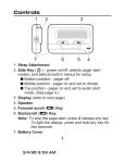
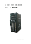
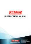
Single-channel all-digital AC servo drives
ATTENTION
QS6 Series
User Manual
This manual is only for drivers with 20XX (or higher) version.
Do not use this manual for drivers with 10XX version.
Adtech (Shenzhen) CNC Technology Co., LTD
Address: 5th floor,27-29th Bulding,Tianxia IC Industrial Park,
MaJiaLong, Yiyuan Road, Nanshan District, Shenzhen City, China
Tel.: (+86-755) 2609 9116
Fax: (+86-755) 2672 2718
PC:518052
Website: www.adtechen.com
Single-channel all-digital AC servo drives QS6 Series
Copyright Notice
The property rights of all the parts of the manual belong to Adtech
(Shenzhen) CNC Technology Co., Ltd. (Adtech for short), and any form of
imitation, copying, transcription or translation by any company or individual
without the permission is prohibited. This manual does not include any form of
assurance, standpoint expression, or other intimations. Adtech and the stuffs have
no responsibility for any direct or indirect disclosure of the information, benefit
loss or business termination of this manual of the quoted product information. In
addition, the product and the information mentioned in this manual are for
reference only, and the content is subject to change without notice.
ALL RIGHTS RESERVED!
Adtech (Shenzhen) CNC Technology Co., Ltd
-1-
Single-channel all-digital AC servo drives QS6 Series
Basic Information of Manual
Item
Initial
Version
Total
Manual Preparation
Layout
No.
Uploading
No.
Pages
Engineer
Engineer
QS6
2011-3-29
A0101
42
GUO Yang
Proofreading Records
Date
Version/Page
Result
Confirmation
-2-
GUO Yang
Single-channel all-digital AC servo drives QS6 Series
Precautions and Explanations
※Transport and storage:
) Do not stack product package more than six layers;
) Do not climb, stand on or place heavy stuff on the product package;
) Do not pull the cable still connecting with machine to move product.
) Forbid impact and scratch on the panel and display;
) Prevent the product package from humidity, sun exposure, and rain.
※Open-box inspection:
) Open the package to confirm the product to be purchased by you.
) Check damages situation after transportation;
) Confirm the integrity of parts comparing with the parts list or damages
situation;
) Contact our company promptly for discrepant models, shortage accessories,
or transport damages.
※Wiring
) Ensure the persons involved into wiring and inspecting are specialized staff;
) Guarantee the product is grounded with less than 4Ω grounding resistance.
Do not use neutral line (N) to substitute earth wire.
) Ensure grounding to be correct and solid, in order to avoid product failures or
unexpected consequences;
) Connect the surge absorption diodes to the product in the required direction,
otherwise, the product will be damaged;
) Ensure the power switch is OFF before inserting or removing plug, or
disassembling chassis.
※Overhauling
) Ensure the power is OFF before overhauling or components replacement;
) Make sure to check failures after short circuit or overloading, and then restart
the machine after troubleshooting
) Do not allow to frequently connect and disconnect the power, and at least one
minute interval between power-on and power-off.
※Miscellaneous
) Do not open housing without permit;
) Keep power OFF if not in use for a long time;
) Pay close attention to keep dust and ferrous powder away from control;
) Fix freewheel diode on relay coil in parallel if non-solid state relay is used as
output relay. Check whether power supply meets the requirement to ensure
not burning the control.
) Install cooling fan if processing field is in high temperature, due to close
relationship between service life of the control and environmental
temperature. Keep proper operative temperature range for the control: 0℃ ~
60℃.
) Avoid to use the product in the overheating, humid, dusty, or corrosive
environments;
) Add rubber rails as cushion on the place with strong vibration.
※Maintenance:
Please implement routine inspection and regular check upon the following items,
under the general usage conditions (i.e. environmental condition: daily average 30℃, load
rate: 80%, and operating rate: 12 hours/ day)
●
Routine Inspection
Routine
Regular Check
One year
●
●
●
●
Confirm environmental temperature, humidity,
dust, or foreign objects.
Confirm abnormal vibration and noise;
Check whether vents are blocked by yarn etc..
Check whether solid components are loose
Confirm whether terminal block is damaged
-3-
Single-channel all-digital AC servo drives QS6 Series
Contents
PREFACE ........................................................................................................................................ - 6 1.1 Introduction ...................................................................................................................... - 8 1.2 Technical Specifications of Servo Drive ............................................................................ - 9 CHAPTER II INSTALLATION.................................................................................................. - 10 2.1 Installation Environment ................................................................................................... - 10 2.1.1 Installation of electric control cabinet .................................................................... - 10 2.1.2 Heating devices around servo drive....................................................................... - 10 2.1.3 Vibration devices around servo drive .................................................................... - 10 2.1.4 Use under harsh environments............................................................................... - 10 2.1.5. Jamming equipment around the servo drive .......................................................... - 10 2.2 Driver Installation.............................................................................................................. - 11 2.2.1 Installation environment ........................................................................................ - 11 2.2.2 Ventilation interval ................................................................................................ - 11 2.2.3 Installation method ................................................................................................ - 12 2.2.4 Installation dimension............................................................................................. - 12 CHAPTER III WIRING.............................................................................................................. - 15 3.1 Standard wiring ................................................................................................................. - 15 3.1.1. QS6AA015M/030M/050M Servo Wiring Breakdown Illustration: ..................... - 19 3.1.2. QS6AA050M3 Servo Wiring Breakdown Illustration: ......................................... - 20 3.2 Distribution........................................................................................................................ - 21 3.2.1 Power supply terminal ............................................................................................ - 21 3.3.2 Control signal CN3 terminal and feedback signal CN1 terminal ........................... - 21 3.3 Terminal function .............................................................................................................. - 21 3.3.1 Power supply terminals: JUT-1.5-4 cold pressured terminal................................. - 21 3.3.2 Control signal input and output terminal: DB36 connector for CN1 Block .......... - 22 3.3.3 Feedback signal terminal of encoder: DB20 connector for CN2 block .................. - 24 3.4 Principles of input and output interfaces ........................................................................... - 25 3.4.1 EN, MODE, INTH, CW, and CCW Switch Input Interface ................................... - 25 3.4.2 SRDY, ALM, BRAKE, COIN, and OZ Switch Output Interface .......................... - 25 3.4.3 Pulse Signal Input Interface:................................................................................... - 26 CHAPTER IV PARAMETERS ................................................................................................... - 29 CHAPTER V ERROR ALARM ................................................................................................ - 32 CHAPTER VI DISPLAY AND PARAMETER SETTINGS..................................................... - 34 6.1 Drive Displays ................................................................................................................... - 34 6.2 Keyboard Operation .......................................................................................................... - 34 6.3 Parameter Settings ............................................................................................................. - 35 6.3.1 Parameter settings................................................................................................... - 35 6.3.2、Password input and changes ................................................................................ - 35 6.3.3 Parameter writing: .................................................................................................. - 36 6.3.4, Parameter initialization:......................................................................................... - 36 CHAPTER VII DEBUGGING.................................................................................................... - 36 7.1 Power Supply Timing........................................................................................................ - 36 7.1.1 Power supply wiring............................................................................................... - 36 7.1.2 Power Timing: ........................................................................................................ - 37 -4-
Single-channel all-digital AC servo drives QS6 Series
7.2 Use of Mechanical Brake “BRAKE”................................................................................. - 38 7.3 Operation ........................................................................................................................... - 38 7.3.1 Pre-operation checks .......................................................................................... - 38 7.3.2 JOG Control of Servo System ................................................................................ - 38 7.3.3 Position Control of Servo System........................................................................... - 38 7.3.4 Speed Control of Servo System ............................................................................. - 39 7.3.5 Torque Control of Servo System ............................................................................ - 39 7.3.6 Internal Speed Control Servo System..................................................................... - 39 7.4
Debugging .................................................................................................................. - 40 7.4.1 Gain and rigidity debugging ................................................................................... - 40 7.4.2 Basic Parameters Adjustment Diagrams............................................................... - 40 7.4.3 Position Resolution and Electronic Gear Settings ................................................. - 41 7.4.4 Servo Start and Stop Debugging Features ............................................................. - 42 CHAPTER VIII RS232 COMMUNICATION ......................................................................... - 43 8.1 Communication Line Connection...................................................................................... - 43 -
-5-
Single-channel all-digital AC servo drives QS6 Series
Preface
Improper operation may cause the accidents. Be sure to read the manual
carefully before using the servo drive.
Note:
z
z
z
The Use Manual always updates with the improvement of the servo drive,
without the prior notice.
Any changes for this product without our permit will cause the warranty
terms to be automatically terminated, and we have no responsibility to
assume the consequences arising from it.
Please pay special attention to and strictly comply with the following
warning signs.
Wrong operation could produce serious consequences, such
as personal injuries or product damages.
Wrong operation could cause personal injuries or product
damages.
Wrong operation could cause personal injuries or produce
alarm malfunction.
Safety Description
z
z
z
z
z
z
z
z
Pay attention to use isolation transformers for AC220V and AC380V two series power
input of drive.
Match drive terminals U/V/ W with motor U/V/W respectively.
Do not intend to use the design and manufacturing of this product to be a threat of
personal security system;
Consider the security protection measures while using this product, in order to prevent
accidents resulted from wrong operations.
Disconnect power for more than 5 minutes before disassembling this drive.
Require maintenance personnel to have the relevant expertise and maintenance
capability.
Do not use damaged or alarming failed drive.
Store and transport this product upon the storage and transportation requirements.
-6-
Single-channel all-digital AC servo drives QS6 Series
z
z
z
z
z
z
z
z
z
z
z
z
z
z
Pack the product properly while transit shipment.
Do not impact on the servo drive externally.
Avoid the vibration and strictly prohibit to pound on the drive.
Install in the control cabinet with adequate protection level.
Install in the environment without strong electromagnetic interference.
Keep good cooling conditions.
Prevent the product from the intrusions of dust, corrosive gases, conductive objects,
liquids and flammable and explosive substances.
Prevent the product from the damages of non-excessive dust, acid and alkali corrosive
gases, and explosive gas.
Do not connect and disconnect drive power supply frequently.
Do not touch still hot cooler and motor after running for a while.
Connect two ends of relay with freewheeling diode in parallel while connecting relay
externally for output signal.
Select the drive to match motor.
Select rated torque of servo motor to be bigger than effective continuous load torque.
Depend on different motor to select 220V power supply input 20A/30A/50A drives or
380V power supply input 50A/75A drives.
-7-
Single-channel all-digital AC servo drives QS6 Series
Chapter I Overview
1.1
Introduction
Modern industrial automation technology is the key technology in the information society, in
which AC servo technology is the core technology, which has developed since the early eighties,
to be increasingly sophisticated in technology and improved in performance. Now this
technology has been widely used in automation field, such as CNC machine tools, printing
packaging machinery, textile machinery, and automated production lines.
Modern servo technology will significantly improve production efficiency, product quality,
and economic benefits, with the increasing development of AC servo technology in full-digital,
open-style, and intelligence.
This AC servo drive is a self-developed new generation fully digital AC servo drive, mainly
using the latest digital signal processor DSP technology and large-scale programmable FPGA
technology as the core computing units and intelligent IPM power module, with many
advantages, such as fast response, perfect protection, and high reliability. It is applicable to highprecision CNC machine tools, automatic production lines, machinery manufacturing and other
industrial control automations.
This drive is a new generation full-digital AC servo drives, characterized by high
integration and small volume for installation, which has been a desired product for energy
conservation and economic benefits enhancement in the industrial automation.
This servo drive has the following advantages in comparison with the previous servo drives:
z
z
z
z
z
z
z
z
z
z
z
z
z
z
Motor power supports 220V power input 100W ~ 3.7KW and 380V power input 3.7W ~
11KW
Torque, speed, location, point to point positioning and hybrid switching features are
available.
Multiply control modes can be used, such as position control, speed control, torque control,
electric tool control and JOG control.
Built-in braking system is capable to meet large load applications.
Built-in 4-position positioning control instruction freely plans point to point positioning
control.
Own encoder can feed back position signal to the servo drive, and constitute the semiclosed-loop control system with the open-loop position control.
Speed regulation ratio is 1:5000, with stable torque feature from low speed to high speed.
The maximum speed of servo motors can reach to 6000 RPM.
Control positioning accuracy can achieve ± 0.01%.
Improved space vector control algorithm generates bigger torque and less noise than the
average SPWM.
300% overload capacity guarantees the load capability is strong.
Wide supply applicative range: ~ 220V ± 20% or ~ 380V ± 20%.
Perfect protection functions are made for over-current, overvoltage, overheating, and
encoder faults.
A variety of display functions: including motor speed, motor current, motor position,
position deviation, pulse number, pulse frequency, straight-line speed, input and output
diagnostic interface, and historic alarm records etc.
-8-
Single-channel all-digital AC servo drives QS6 Series
1.2 Technical Specifications of Servo Drive
Input Power
Drive current
AC220V -15%~+10%
20A
30A
Adaptive motor
Input Power
Drive current
Adaptive motor
≤1.0KW
≤2.3KW
Usage temperature
Working:45℃
Relative Humidity
ATM
40% ~ 80% with non-condensing
86-106 kpa
①Position Control ②JOG Control ③Speed Control ④Torque
Control ⑤Position and speed control
⑥Internal impulse control ⑦Electric tool control ⑧Position and
torque control
①Pulse + direction ②CW+CCW pulse
③AB Two-phase orthogonal pulse
0.01%
≤200Hz
≥500kHz
Control Mode
Pulse command
Control precision
Response frequency
Pulse frequency
Speed regulation
ratio
Regenerative brake
Electronic Gear
Overload capability
Feedback pulse
Displays
Protection
50A
≤7.5KW
50A
75A
100A
≤3.7KW
≤5.5KW
≤7.5KW
AC380V -15%~+10%
75A
≤11KW
150A
≤11KW
Storage:-40℃~55℃
1:5000
Built-in
1/30000~30000/1
≥300%
2500p/r
Motor speed, motor current, motor torque, motor position, position
deviation, command pulse, pulse frequency, straight-line speed, input
and output diagnostics
Overspeed,overcurrent,overvoltage,undervoltage,overload,out-oftolerance,Ecode fault, over temperature, internal IC fault, and module
fault
-9-
Single-channel all-digital AC servo drives QS6 Series
Chapter II Installation
z
z
z
z
z
z
Satisfy the requirement and conditions of environment for product storage and installation;
Ensure to use fire-proof material for installation; in order to avoid fire, forbid to install on or
near the flammable substances;
Install servo drive in the electric control cabinet to prevent the intrusion of dust, corrosive
gases, conductive objects, liquids, and combustibles;
Avoid vibration and impact on the servo drive and servo motor;
Consider to install lighting protection device under the usage environment of the servo drive;
Prohibit pulling the cables of servo motor, motor shaft, and encoder.
2.1 Installation Environment
2.1.1 Installation of electric control cabinet
The ambient temperature directly affect lift span of the drive. However, heating of electric
equipment in the electric control cabinet and cooling condition of control cabinet will impact on
the temperature around the servo drives. Therefore, when the chassis design is considered, the
cooling system of drive an control cabinet configuration should be taken into account, to ensure
the ambient temperature of servo drive to be below 55 ℃, relative humidity to be below 95%.
Besides, long-term security working temperature should be below 45 ℃.
2.1.2 Heating devices around servo drive
Servo drive working under high temperature conditions will significantly reduce its service
life, and easily generate failures. Thereby, the ambient temperature should be guaranteed to be
below 55 ℃ under the conditions of thermal convection and heat radiation.
2.1.3 Vibration devices around servo drive
All kinds of anti-vibration measures should be adopted to prevent the servo drive from
vibrations, which should be guaranteed to be 0.5G (4.9m/s2) below.
2.1.4 Use under harsh environments
When used in harsh environments, servo drive will contact with corrosive gases, moisture,
metal dust, water and processing liquids, which shall bring the malfunctions. Therefore, noise
filter and other anti-interference measures should be taken to ensure the drive to work normally.
Please note that leakage current will be increased after installed noise filter. In order to avoid the
above situation, you can select isolation transformer, in particular, control signal lines of drive
are easy to be interfered and reasonable wiring and shielding measures should be considered.
2.1.5. Jamming equipment around the servo drive
Jamming equipment around the servo drive will produce interference, resulted in false
operation. Noise filter and other anti-jamming measures can be used to guarantee drive to operate
normally. Please note that leakage current will increase after noise filter added. To avoid the
above situation, isolation transformer can be adopted. Please pay special attention that reasonable
wring and shielding measures can prevent drive control signal from interference.
- 10 -
Single-channel all-digital AC servo drives QS6 Series
2.2 Driver Installation
z
z
z
Install servo drive in the electric control cabinet with good lighting protection.
Install servo drive upon the required direction and interval; good cooling condition is must.
Do not install servo drive on or near the combustibles, in order to prevent fires.
2.2.1 Installation environment
1) Protection
Servo drive structure has no protection, and therefore it must be installed in the electric control
cabinet with excellent protection, to prevent contact with corrosive and flammable gases, and
avoid the intrusion of the conductive objects, metal dust, oil mist and liquids.
2) Temperature
Ambient Temperature is 0 ~ 55 ℃, and long-term security working temperature is below 45 ℃.
Excellent cooling conditions should be guaranteed, and relative humidity is 95%.
3) Vibration and impact
Installation should avoid vibration and vibration release measures should be taken to control it to
be 0.5 (4.9m/S2) below. Besides, when installing the drive, heavy pressure and impact are not
allowed.
2.2.2 Ventilation interval
- 11 -
Single-channel all-digital AC servo drives QS6 Series
2.2.3 Installation method
1)
2)
3)
Installation direction: the direction of the normal installation is vertical upright orientation.
Fixing: 4 pieces M5 screw on servo drive should be fixed.
Ventilation and cooling: natural cooling mode is adopted. Cooling fan should be installed in
the electric control cabinet.
z
Do not hit motor or motor shaft while disassembling pulley, in order to prevent encoder
from damage; use spiral drawing tools for disassembly;
Prohibit large axial and radial load on motor; suggest to select flexible coupling to connect
the load;
Fix motor with washer fastening to prevent the motor from loosing.
z
z
2.2.4 Installation dimension
1) QS6AA015M Outline Dimensional Drawing:
- 12 -
Single-channel all-digital AC servo drives QS6 Series
2) QS6AA030M2 Outline Dimensional Drawing:
- 13 -
Single-channel all-digital AC servo drives QS6 Series
3) QS6AA050M2 Outline Dimensional Drawing:
- 14 -
Single-channel all-digital AC servo drives QS6 Series
Chapter III Wiring
z
z
z
z
z
Make sure the usage power supply (AC220V and AC380V two series are available for this
drive) for the drive and use isolation transformer.
Match drive terminals U/V/W with motor U/V/W respectively;
Consider the security protection measures for design and assembly while using this product,
in order to avoid accidences resulted from wrong operations;
Ensure the good grounding for drive and motor;
Disconnect the power for more than 5 minutes before disassembling this drive.
3.1 Standard wiring
This AC servo drive wiring is concerned with the used motor and control modes.
General wiring:
1. Wiring of encoders and control uses a stranding with shield layer. In order to reduce
interference, the wire is required to be as short as possible. Shielded cable (PE) should be
connected, and the maximum wire connection can reach 10M for general application;
however, it is not recommended to use more than 10M.
2. Power cords connection uses the corresponding cables with motor current specifications.
The high voltage level of cable is required to greater than motor. Shielded cable (PE) is must.
The maximum wire connection can reach 10M for general application; however, it is not
recommended to use more than 10M.
3. Three-phase voltage requires an extra reactor;
4. Single-phase power supply requires an extra isolation transformer.
- 15 -
Single-channel all-digital AC servo drives QS6 Series
Operating power
supply input
Single-phase or
three-phase
(12-core shielded cable)
Control signal input
36-core
(Green)
(White)
(brown)
(Grey)
(Blue)
(Yellow)
(Black)
(Red)
(Orange)
(Purple)
(Pink)
(Light green)
(White)
(Black)
(Yellow)
To U-pin
16-core shielded cable
Motor power supply
terminal
Servo Drive output
(Red)
(Black)
(Black and white)
Drive
Motor encoder
(Brown)
(Brown
(Yellow)
(Green)
(White)
(Purple)
(Orange)
(Blue)
(Grey)
(Orange and white)
(Red)
(Red white)
20-core
Shielding
Wiring Diagram of QS6 Matching ACH Series750W below Motor
- 16 -
Single-channel all-digital AC servo drives QS6 Series
QS6AA015M External Wiring Instruction
RS232 Communication
Terminal
Single-phase
AC220V/RS232
I/O control terminal
Servo drive
- 17 -
Encoder terminal
Single-channel all-digital AC servo drives QS6 Series
QS6AA/030M/050M Universal
External Wiring Instructions
RS232 Communication
Terminal
Three-phase or Single-phase
220AC/RS232
I/O control terminal
Servo drive
Encoder terminal
QS6AA050M3 External Wiring
Instructions
RS232 Communication
Terminal
I/O control terminal
Servo drive
Encoder terminal
Insulation in AC 2000V or more
- 18 -
Single-channel all-digital AC servo drives QS6 Series
3.1.1. QS6AA015M/030M/050M Servo Wiring Breakdown Illustration:
QS6 Servo Drive
Servo Enable
Motor
Control Method
Position Against
Forward Limit
Reverse Limit
Orientation
Servo Alarm
Servo Ready
Encoder
Break out
Z Encoder Output
Encoder Signal
Position Command Pulse
Direction Command Pulse
Speed or Torque Commands
±10vRated Torque
- 19 -
Single-channel all-digital AC servo drives QS6 Series
3.1.2. QS6AA050M3 Servo Wiring Breakdown Illustration:
Isolating Transformer
Single-phase or
three-phase
or
Servo Drive
three-phase AC380V
Single-phase
AC220v
Servo Enable
Control Method
Position Against
Forward Limit
Servo Motor
Reverse Limit
Encoder Z signal
Orientation Complete Signal
Ready Signal
Servo Alarm
Public-side Output Signal
Encoder
Brake Position Terminal
Brake Negative Terminal
Analog Signal
Pulse
Signal
Direction Signal
Encoder Signal
Standard Wiring Diagram
- 20 -
Single-channel all-digital AC servo drives QS6 Series
3.2 Distribution
3.2.1 Power supply terminal
z
z
z
z
Diameter of R, S, T, PE, U, V, W terminals should be ≥ 1.5mm ² (AWG14-16).
Wiring terminals of this product use JUT-2.5-4 cold pressured terminals, which should be
made sure to be connected firmly.
Three-phase isolation transformer power supply should be used to reduce the possibility of
electrical injuries. It is better to use noise filter between the city power supply and isolation
transformers, to improve anti-jamming capability for the system.
Please install the non-fuse type (NFB) circuit breakers, so that the external power can be
promptly cut off while drive failures happen.
3.3.2 Control signal CN3 terminal and feedback signal CN1 terminal
1) Diameter: The shielded cable (preferably use twisted-pair shielded cable) should be selected;
diameter ≥ 0.12 mm ²; the shield layer must connect with PE terminal.
2) Length: cable length should be as short as possible; the control signal CN3 cable should not
exceed 3 meters; feedback signal CN1 and cable lengths should not exceed 10 m.
3) Distribution: it should be far away from power lines, to prevent interference.
4) Please install surge absorption components for inductive components (coil) in the relevant
lines, e.g. DC coil anti-parallels freewheeling diode, and AC coils connects RC absorption
circuit in parallel.
3.3 Terminal function
3.3.1 Power supply terminals: JUT-1.5-4 cold pressured terminal
PIN
1
2
3
4
5
6
7
8
9
10
11
Mark
R
S
T
PE
U
V
W
PE
r
t
PE
Signal Name
Signal function
Three-phase or single-phase main
power
AC220V or AC380V50HZ cannot connect with
the motor UVW
Grounding
Connecting with the main power ground
Servo Motor
Matching motor UVW one by one
Grounding
Connecting motor housing
220V drive; no such terminal:
control power supply
Control power220V 50HZ
Grounding
Connecting with control power ground
Note: When using AC220V power supply, the drive has no 9,10,and 11 terminals.
- 21 -
Single-channel all-digital AC servo drives QS6 Series
3.3.2 Control signal input and output terminal: DB36 connector for CN1 Block
PIN
28
29
9
10
15
Signal Name
Encoder Signal Z
Input signal
power supply
positive
Servo Enable
Control method
or function
selection
Mark
I/O
CZ+
output
CZ-
output
INCO
M+
input
Power supply positive of input terminal is used to drive
the opt coupler DC12 ~ 24V of input terminal, current ≥
100mA
input
Servo enable input terminals
EN ON: allow the drive to work
EN OFF: drive off, stop working
Motor in a free state
Set P5 = 1 to shield this feature
Note 1: The motor must be stationary between EN OFF
and EN ON.
Note 2: To EN ON, at least wait for 50ms and then enter
the command
input
①When position and speed function options are valid,
speed control is selected, and P4 = 4 can configure this
function.
② When internal speed option is valid, the internal rate
can be selected, and P4=7,P35, P36, P37, and P38 can
configure this function.
EN
MODE
Signal function
Open-collector output, to end the OUTCOM
- 22 -
Single-channel all-digital AC servo drives QS6 Series
11
Command pulse
prohibition
12
13
14
6
5
4
3
1
INTH
input
Forward limit
CW
input
Reverse limit
CCW
input
CLR
Input
SRDYSRDY+
ALMALM+
output
output
output
output
COIN+
output
COIN-
output
Alarm clear
signal
Ready signal Ready signal +
Servo alarm
Positioning
completed
2
25
Pulse signal+
24
Pulse signal-
27
26
19
18
Direction signal+
Direction signalAnalog input
Analog GND
Encoder Signal
Z+
Encoder Signal
ZEncoder Signal
B+
Encoder Signal
BEncoder Signal
A+
Encoder Signal
A-
30
31
32
33
34
35
PULSE
+
PULSE
SIGN+
SIGNVin
Vgnd
input
input
input
input
input
input
OZ+
output
OZ-
output
OB+
output
OB-
output
OA+
output
OA-
output
①Position command pulse prohibits input terminals, and
the parameter is valid under the position mode.
0: Invalid, does not detect the signal INTH
1: Detection INTH signal effective
2: Test INTH effective and remove the remaining pulses
① Motor Forward limit input signal;
② P4 = 7, the motor forward rotating JOG input
signal;
① Motor reverse limit input signal;
② P4 = 7, the motor reversely rotating JOG input signal;
Alarm clear signal
Alarm output of servo ready for trouble-free is valid
Servo alarm output is valid
① Positioning completion output, when the position
deviation is less than the set range, the output is valid;
② Output of internal pulse running completion is valid;
③ When the torque reaches P50 percentage, output
parameter P2 can configure this feature.
External position control command;
Parameter P10 setting mode
0: Pulse + Sign: pulse plus direction
1: CW + CCW: forward and reverse control
2: A + B: 90 °orthogonal pulse
External speed or torque command:0~±10V
motor encoder Z signal output
Motor encoder B signal output
Motor encoder A signal output
- 23 -
Single-channel all-digital AC servo drives QS6 Series
3.3.3 Feedback signal terminal of encoder: DB20 connector for CN2 block
CN2 External Wiring Description
QS6 Series Encoder CN2
16-core Shielding
Cable
Drive CN2
Pin
Jiabao or Huada Series Servo Motor
Motor Encoder
Signal
Pin
(Black)
(Black and
white)
(Brown)
(Brown
(Yellow)
(Green)
(White)
(Purple)
(Orange)
(Blue)
(Grey)
(Orange
and white)
(Red)
(Red white)
Shielding
Pin
No.
Color
Name
Description
PG input
phase
PG input
phase
PG input
phase
PG input
phase
PG input
phase
PG input
phase
phase A
1
Black
A+
2
Black
and white
A-
3
Brown
B+
4
Brown
and white
B-
5
Yellow
C+
6
Green
C-
Red
5V
PG Power +5V
—
—
—
7
8
9
10
phase /A
phase B
phase /B
phase C
phase /C
Pin
No.
Color
Name
11
White
U+
12
Purple
U-
13
Orange
V+
14
Blue
V-
15
Gray
W+
16
17
18
19
20
- 24 -
Orange and
white
Red and white
W-
Description
PG input phase U
phase
PG input phase /U
phase
PG input phase V
phase
PG input phase /V
phase
PG input phase W
phase
PG input phase /W
phase
0V
PG Power 0V
—
—
—
Single-channel all-digital AC servo drives QS6 Series
3.4 Principles of input and output interfaces
3.4.1 EN, MODE, INTH, CW, and CCW Switch Input Interface
Drive side
Switch Input Interface
1) Power supply, DC12 ~ 24V, current ≥ 100mA is provided by the user;
2) Please note the reversed current polarity will cause servo drive to fail to work properly.
3.4.2 SRDY, ALM, BRAKE, COIN, and OZ Switch Output Interface
Drive side
Switch Input Interface
1) External power supply should be provided by the user; however please note the reversed
current polarity will lead servo drive to be damaged.
2) Output is open collector form. OZ, SRDY, COIN, and ALM signal maximum current is
20mA; BRAKE signal maximum current is 50mA; therefore BRAKE can directly drive
relay, while the OZ, SRDY, COIN, and ALM signal cannot drive relay; an external power
supply maximum voltage is 25V. Thereby, the switch output signal of the load must meet
the qualification requirements. Excessive limit requirement or output directly connecting
with the power supply will cause servo drive to be damaged.
3) If the load is the inductive load with relay etc, you must anti-parallel freewheeling diode at
both ends of the load. The reversed freewheeling diode will cause servo drive to be damaged.
- 25 -
Single-channel all-digital AC servo drives QS6 Series
3.4.3 Pulse Signal Input Interface:
Drive side
Pulse signal input interface of the differential drive mode
Drive side
Pulse signal input interface of the single-ended drive mode
1) In order to properly transmit the pulse of traffic data, the differential-driven approach is
recommended;
2) After adopting differential drive mode, AM26LS31, MC3487 or similar RS422 line drivers
should be used;
3) Please use single-ended drive mode, which will reduce operating frequency. Resistance R
values can be determined upon pulse input circuit, drive current 10 ~ 15mA, and external
power supply maximum voltage limitation 25V. Empirical data are as follows: VCC = 24V,
R = 1.3 ~ 2k; VCC = 12V, R = 510 ~ 820Ω; VCC = 5V, R = 82 ~ 120Ω.
4) Using single-ended drive mode and the external power supply is provided by the user. Please
pay attention that the reversed power supply polarity will lead servo drive to be damaged.
5) Please refer to the following table for specific pulse input modes, and required pulse
frequency ≤ 500 kHz.
- 26 -
Single-channel all-digital AC servo drives QS6 Series
Pulse Input Modes
Pulse
command
CW
CCW
P14Settings
PULS
Pulse + sign
0
Pulse + sign
SIGN
PULS
CCW Pulse
CW Pulse
1
CW+CCW Pulse
SIGN
PULS
A + B Pulse
2
A+B 90°
Orthogonal pulse
SIGN
Pulse Input Timing Parameters
Parameter
tck
th
tl
trh
trl
ts
tqck
tqh
tql
tqrh
tqrl
tqs
Differential Driver Input
>2uS
>1uS
>1uS
<0.2uS
<0.2uS
>1uS
>8uS
>4uS
>4uS
<0.2uS
<0.2uS
>1uS
Single-ended driven input
>5uS
>2.5uS
>2.5uS
<0.3uS
<0.3uS
>2.5uS
>10uS
>5uS
>5uS
<0.3uS
<0.3uS
>2.5uS
Pulse + Sign Input Interface Timing Diagram (Pulse Frequency ≤ 500kHz)
- 27 -
Single-channel all-digital AC servo drives QS6 Series
CW + CCW Pulse Input Interface Timing Diagram (Pulse Frequency ≤ 500kHz)
Servo Motor Optical Encoder Input Interface
- 28 -
Single-channel all-digital AC servo drives QS6 Series
Chapter IV Parameters
z
z
Personnel involved into parameter adjustment must understand the meaning of parameters,
for the wrong settings may cause equipment damage and personnel injury;
It is suggested that all the parameters adjustment should be under the situation of the servo
motor stationary.
Parameters Description
Parameter
No.
P0
P1
Parameter Name
Paramet
er Range
Factory
Default
0-9999
0
0-Rotational speed(RPM)
1-Motor current(A)
2-Motor loading rate
3-Motor position: 4-bit lower
4- Motor position: 4-bit higher
5- Input pulse : 4-bit lower
6-Input pulse: 4-bit higher
7-Position deviation
8-Input status
9-Analog input
10-Pulse frequency
0-10
400
0
Function Description
P2
P3
Software version
Parameter
password
Motor model
Boot display
P4
Control mode
0-Position mode: external pulse input;
1-JOG mode: key control;
2-Speed mode: external analog voltage input;
3-Torque mode: external analog voltage input;
4- Position and speed mode: MODE control;
5-Position and torque mode: MODE control;
6-CW CCW: external signal jog mode
Section 7-4: speed control
0-7
0
P5
Servo
control
enable
0-Valid
1-Invalid: forcibly lock shaft
0-1
0
P6
Servo
signal
function
input
INTH
0-Invalid
1-Input pulse prohibition and position deviation
clear
2 - Input pulse prohibition and position
deviation not clear
0-1
0
P7
Limit
control
input
0-Active LOW without alarm;
1- Active LOW without alarm;
2- Active HIGH without alarm;
3- Active LOW with alarm;
4- Active HIGH with alarm;
0-4
0
- 29 -
Single-channel all-digital AC servo drives QS6 Series
P8
Coin output mode
P9
Alarm output mode
P10
Pulse mode
P11
Motor direction
P12
P13
P14
P15
P16
P17
P18
P19
P20
P21
P22
P23
P24
P25
P26
Electronic gear numerator
Electronic gear denominator
Positioning completion scope
Position deviation alarm range
Position gain
Position feed-forward
Position smoothing constant
Position acceleration time
Position deceleration time
Speed gain
Speed integral
Acceleration time (speed)
Deceleration time (speed)
Encoder speed detection filter
Analog maximum speed
P27
Torque maximum speed
P28
P29
P30
P31
Analog input filter coefficient
Analog input voltage at zero
Inertia ratio
Analog input percentage
P32
P33
Encoder lines frequency
splitting
Encoder alarm permit
P34
0-Positioning completion
1-Torque reaching
0-Normal close type
1-Normal open type
0 - Pulse + direction: normal
direction;
1-Pulse+pulse: normal direction
2 - Orthogonal pulse: normal
direction
0 - Normal
1 - Reverse
0-prohibition
0- prohibition
The corresponding speed when
analog input is in maximum.
The maximum rotation speed under
the mode of torque.
0- prohibition
0-1
0
0-1
0
0-2
0
0-1
0
1-32000
1-32000
0-32000
0-32000
1-2000
0-32000
0-1000
0-32000
0-32000
1-1000
1-32000
0-32000(ms)
0-32000(ms)
0-1000
1-5000
1
1
5
10000
100
0
0
0
0
100
100
50
50
0
2000
1-5000
2000
0-1000
0-equivalent 100%
0-1000
0-500
0
0
0
0
0 - not use frequency splitting
0-127
0
0-detect encoder
1-not detect encoder
0-1
0
JOG speed
0-5000
1000
P35
Internal speed 1
0-5000
100
P36
Internal speed 2
0-5000
200
P37
Internal speed 3
0-5000
300
P38
Internal speed 4
0-5000
400
P39
Internal position 1
0-±32000
100
P40
Internal position 2
0-±32000
200
P41
Internal position 3
0-±32000
300
P42
Internal position 4
0-±32000
400
P43
Communication address
0-255
0
- 30 -
Single-channel all-digital AC servo drives QS6 Series
P44
Communication
baud
rate
Torque
reaching
percentage
Torque percentage of
motor stationary
P45
P46
9600
0-this function prohibition
Other values-this function permit
0-100
100
0-100
0
0
600
150
P47
Start
delay
of
electromagnetic brake
P48
Stop
delay
of
electromagnetic brake
0 - 32000
(ms)
0 - 32000
(ms)
P50
P51
Current loop gain
Current loop integral
10-4000
1-2000
z
z
z
z
0
It is recommended that all parameter settings and modification should be implemented
when the motor is prohibited.
All parameters (only P2 parameter will be effective after re-electrified when disconnecting
power) settings will be effective after just pressing "Enter", without re-electrifying; however,
parameter writing should be performed for long-term preservation;
When the power of drive is OFF, please wait for more than 30 seconds and then re-electrify
it.
When the drive is used fro numerical control system, the parameters P12 and P13 are
calculated as follows:
P12
Mechanical reduction ratio * System pulse equivalent * 10000
=
P13
Screw pitch (mm)
General CNC pulse equivalent: 0.001mm
- 31 -
Single-channel all-digital AC servo drives QS6 Series
Chapter V Error Alarm
z
z
z
z
Do not touch drive and motor within 5 minutes after driver and motor power-off, to prevent
person from injury due to electric shock;
Allow to use drive after drive alarm code troubleshooting while drive failure alarms;
Show Er0-xx and blinking while error is found, wherein xx refers to alarm code;
Operate drive to view and modify parameters after alarming.
Alarm list
Alarm Code
ER0-00
Alarm Content
Normal
Cause of Malfunction
1)
2)
3)
ER0-01
Motor speed is too high
4)
5)
6)
7)
8)
Encoder wiring error
Encoder damage
Encoder cable is too long, resulting in the low encoder
supply voltage
Running too fast
Input pulse frequency is too high
Electronic gear ratio too big
Servo system instability causes overshooting
Circuit Board Fault
ER0-02
The main circuit supply
voltage is too high
1) The supply voltage is too high (more than +20%)
2) Disconnect the brake resistor wiring
4) The internal regenerative braking transistor is broken
5) The internal regenerative braking circuit capacity is too small
6) The circuit board failure
ER0-03
The main circuit power
supply voltage is too
low
or
drive
temperature is too high
1) The supply voltage is too low (less than -20%)
2) Temporary power outages for more than 200mS
3) Power start circuit failure
4) The circuit board failure
5) The drive temperature is too high
ER0-04
Tolerance alarm
1)
2)
3)
4)
5)
6)
7)
8)
Mechanical choked to death
Input pulse frequency is too high
Encoder zero change in
Encoder wiring error
P16 position loop gain is too small
Less torque
P15 parameter setting is too small
P15 = 0 shields this feature, resulted in no alarm
ER0-05
Drive temperature is
too high
1)
2)
The ambient temperature is too high
Bad cooling fan
3)
4)
Broken temperature sensor
Motor current is too big
- 32 -
Single-channel all-digital AC servo drives QS6 Series
5)
6)
7)
Internal regenerative braking circuit failure
Broken internal regenerative braking transistor
Circuit Board Failure
ER0-06
EEPROM
writing
memory error on drive
Chip U19 failed and should be replaced.
ER0-07
CW Motor
limit
Forward
Hit the forward limit switch, you can set the parameter P7 = 0 to
shield this feature or reversely rotate motors.
ER0-08
CCW Motor Reverse
limit
Hit the reverse limit switch, you can set the parameter P7 = 0 to
shield this feature or reversely rotate motor.
ER0-09
Encoder fault
1)
2)
3)
4)
Encoder damage
Encoder wiring is damaged or broken
P33 = 1 shields this feature, resulted in no alarm
Encoder cable is too long, resulting in low encoder supply
voltage
Motor overload alarm
Overload excesses the parameters of motor rated torque:
More than 150% rated overload: over 10000 ms;
More than 300% rated overload: over 1000ms;
More than 500% rated overload: over 10ms
The machine is stuck for rigidity is adjusted too strong;
Speed increase and decrease are too fast.
ER0-11
Power module fault
1)
2)
3)
4)
5)
6)
7)
8)
9)
Over-current
Voltage is too low
Motor insulation is damaged
Gain parameter is set incorrectly
Overload
Temperature is too high
Module is damaged
Interference
Short-circuits occurs among motor cables U, V, and W.
ER0-12
Over-current
1)
2)
3)
Short-circuits occurs among motor cables U, V, and W.
Imperfect grounding
Broken motor insulation
ER0-10
- 33 -
Single-channel all-digital AC servo drives QS6 Series
Chapter VI Display and Parameter
Settings
6.1 Drive Displays
Servo System panel comprises 6 LED digital tube displays and 4 keys. Digital tube is used
to show the various states and parameters of servo drive; key is used to set and access system
parameters.
The servo system is normally displayed with the following 10 methods:
1) Indicating motor speed: parameter P3 = 0, unit: r/min
2) Indicating the motor current: parameter P3 = 1, unit: A
3) Indicating the motor torque percentage: parameter P3 = 2, unit: %
4)Indicating motor operation position 4-bit lower: parameter P3 = 3,unit:pulse
5) Indicating motor operation position 4-bit higher: parameter P3 = 4,unit:pulse
6 Indicating input pulse 4-bit lower: parameter P3 = 5,unit:pulse
7)Indicating input Pulse 4-bit higher: parameter P3 = 6,unit:x1000pulse
8)Indicating position deviation: parameter P3=7, unit: pulse
9) The Input interface diagnoses: Parameter P3=8
Hexadecimal number display data means:
D0= 1: "EN" input is valid;
D1=1: "INTH" input is valid;
D3=1 : "MODE" input is valid;
D4=1 : "CW" input is valid;
D5=1: "CCW" input is valid.
10) Analog input: indicating the size of inputted analog: parameter P3=9;
11)Input pulse frequency: parameter P3 = 10, unit: kHz.
6.2 Keyboard Operation
Drive panel comprises 6 LED digital tube displays and four keys "↑", "↓", "Mode", "Enter" ,
to display various states of the system and set parameters. Key features are as follows:
"↑": parameter number, value increase, or motor running forward under the JOG mode;
"↓": parameter number, value reduction, or motor running reversely under the JOG mode;
"Mode": function options, or the current digital cursor moving left.
"Enter": function key for confirmation, or data entry confirmation.
- 34 -
Single-channel all-digital AC servo drives QS6 Series
Under normal circumstances, press "Mode" to entry ① "parameters" setting, ②"parameter
written", ③ "parameter initialization" , ④ “Alarm display” (it will not be displayed when
no alarm), ⑤ “Display state”, all of which can be cycle selected.
①"Parameter": P1 ~ P61
②"Parameter writing": It is valid when entering right password;
③"Parameters initialization”: It is valid when entering right password;
④ “Alarm display” (the picture shows no alarm)
⑤ “Display state”: Same as indicated content of P3 parameter
When alarm occurs, please adjust to the alarm screen and press “↓” to eliminate alarm.
When password of input system fails to be found, you can access ① "parameters" view,
and enter password to modify P3 parameter; however, other parameters cannot be changed.
6.3 Parameter Settings
6.3.1 Parameter settings
1) Under normal circumstances, press "Mode" to entry ① "Parameters"
2) Press "↑" or "↓" keys to select the parameters number which you
want to modify, and then press "Enter".
3), Press "↑" to auto-add one value, press "↓" key
to auto –reduce one value, and press "Mode" key to shift current
the current number (decimal point position)
to the left, and press "Enter" key for data confirmation.
1) When parameter P1 is imported , only "0" is displayed, i.e. system password does not
display;
2)
The data are invalid and the system return display status under the situation of password
absence.
6.3.2、Password input and changes
Password must be entered into the system for system parameter setting of each boot.P1
parameter input is system password input. When the input password is correct, it can set other
parameters; otherwise other parameters cannot be set.
Password changes must enter the old password firstly, and then you can set the P1
parameters. If system password cannot remember, please use universal password: 11111.
When the password is set to "9999", you can modify parameters without password input for
the next boot.
- 35 -
Single-channel all-digital AC servo drives QS6 Series
6.3.3 Parameter writing:
In the display status, press "Mode" and select to enter
② "parameter writing":
parameter writable state. When changed parameters by user need to save for long term,
parameter writing operation should be implemented. Press "Enter" key for three seconds, and the
parameters will be written in the internal EEPROM, and then press "Enter" key to return, after
writing completion and showing
.
6.3.4, Parameter initialization:
In the display status, press "Mode" and select to entry
③ "parameter
initialization" state.
When the user needs to import the factory system parameter values, press "Enter" key for
three seconds, and parameters except for password will be initialized to be the factory default
values for the system; however these values do not write into the internal EEPROM. If writing is
necessary, please implement writing operation.
After completion and showing
, please press "Enter" key to return.
Chapter VII Debugging
z
z
z
z
z
z
Drives and motor should be grounded reliably, PE should be reliably connected with motor
grounding;
It is recommended that drive power supply is provided through the isolation transformer, to
ensure the safety and anti-jamming capability;
Power supply can be connected after wiring is checked and confirmed to be correct;
The failures should be confirmed to be eliminated prior to re-start, after drive failure alarm;
Do not touch drive and motor within 5 minutes after power-off of drive and motor, in order
to prevent electric shock;
Please pay attention that temperature of drive and motor may be high after they have
worked for a while, in order to avoid burning.
7.1 Power Supply Timing
7.1.1 Power supply wiring
Please refer to Diagram 7-1 for power connection, and then connect the power in the
following order:
1) The power supply is connected into main circuit power supply input terminal (connecting
R/S/T) through the electromagnetic contactor.
2) After Power is connected, wait for about 1.5 seconds delay, and servo ready signal (SRDY)
will be effective. Now it can accept the servo enable (EN) signals, and detect servo enable
effectiveness, driver output effectiveness, electric incentive, and power-on status. When
servo enable is detected to be invalid or alarm occurs, electric incentive circuit will shut
down, and the motor is in a free state.
- 36 -
Single-channel all-digital AC servo drives QS6 Series
3) When the servo enable can be connected together with the power supply, electric incentive
circuit will be connected after approx. 1.5 seconds.
4) Frequent power –on and power –off may damage soft-start circuit and dynamic braking circuit.
Therefore, it is better that power-on and power-off frequency should be limited to be 5 times
per hour, and less than 30 times every day. If the drive or motor is overheating, please wait
for 30 minutes for cooling after troubleshooting, and then re-connection of power.
Power Supply Wiring Diagram 7-1
7.1.2 Power Timing:
- 37 -
Single-channel all-digital AC servo drives QS6 Series
7.2 Use of Mechanical Brake “BRAKE”
Mechanical brake is used to lock the vertical or tilt table connecting motor, to prevent
motor from falling down after power-failure. The motor with brake feature should be selected to
achieve this function.
BRAKE signal of drive is used to control auxiliary relay, which will start brake power
(brake power is provided by the user). BRAKE will be effective in P53 delay time after drive
motor incentives power supply is electrified. When power-off or alarm occurs, drive will autodisconnect BRAKE with signal delay time P54, and then motor incentive power supply will be
disconnected.
When this signal is installed, the brake power supply must have sufficient capacity, and
must use freewheeling diode as surge absorber. Please see diagram below.
7.3 Operation
7.3.1
Pre-operation checks
After completion of the installation and connection, please check the following items before
power-on:
z Whether the power terminal wiring is correct and reliable? Whether the input voltage is
correct?
z Whether power lines and motor wires get short circuit or grounding?
z Whether the control signal terminal is connected correctly? Whether power supply polarity
and size are correct?
z Whether drive and the motor are fixed firmly?
z Whether motor shaft is not connected to the load?
7.3.2 JOG Control of Servo System
When the system parameter is set to be P4 = 1, the servo system is under the mode of JOG
control.
Press "↑", servo motor rotates forward; release “↑", the motor stops. Running speed is
determined by the setting values of parameters P34, P11.
Press "↓" servo motor rotates reversely; release "↓", the motor stops. Running speed is
determined by the setting values of parameters P34, P11.
JOG control acceleration time constant is adjusted through parameters P21; JOG control
deceleration time constant is adjusted through the parameter P22.
7.3.3 Position Control of Servo System
When the system parameters are set to be P4 = 0, P4=4, or P4= 5 and signal is invalid,
- 38 -
Single-channel all-digital AC servo drives QS6 Series
servo system in under position control mode. Running speed is determined by input pulse
frequency; running direction is determined by the input direction and P11; running pulse mode is
set by P10.
When P6 = 1,2 , and INTH signal is valid, this function can be terminated.
Electronic gear is determined by P12 and P13.
Position acceleration time constant is adjusted through parameter P19; position control
deceleration time constant is adjusted through parameter P20.
7.3.4 Speed Control of Servo System
When the system parameters are set to be P4 = 2, or P4 = 4, and MODE is valid, servo
system is in the speed control mode. The maximum operating speed is determined by the
parameters P26 and P31. The maximum operating speed refers to the operating speed when input
voltage is 10V.
Operating speed is determined by Vin1 voltage, and direction is determined by the symbols
of Vin 1 and P11. When P15=2, direction is determined by CW and CCW, wherein, CW and
CCW respectively refer to motor rotation forward and reversely.
Zero-drift of speed control is adjusted through parameter P29, and adjusting this
parameter to set motor speed to be 0 when input voltage is 0V.
Speed control acceleration time constant is adjusted through the parameter P23; speed
control deceleration time constant is adjusted through the parameter P24.
Note: When P7 = 4,under the MODE switch, feeding instruction can be transmitted after
10ms delay of MODE reaching.
7.3.5 Torque Control of Servo System
When P4 = 3, or P4 = 5, and MODE is effective, servo system is in torque control mode.
Torque is determined by the input voltage Vin1. The direction is determined by the symbols of
Vin1and P11. Input voltage is maximum torque when the torque is 10V. The maximum speed
specified by the internal rate of P27.
Zero-drift of torque control is adjusted through the parameter P29, and adjusting this
parameter to set motor speed to be 0 when input voltage is 0V.
Torque can be adjusted through the parameter P45 to gain size compensation adjustment;
bigger value, greater torque.
When the output torque reaches parameter rated current percentage P45, COIN signal is
output. COIN is the pulse signal with the width of 10ms.
7.3.6 Internal Speed Control Servo System
When the system parameter is set to be P7 = 9, servo system is in the internal speed control
mode.
After the input signal MODE (level signal) is input and valid, the motor starts; after the
input signal INTH (NC signal) is input and effective, the motor stops. Speed is determined by the
input signals CW and CCW decision. Please see the below table:
MODE signal
INTH signal
1
CCW signal
CW signal
1
0
0
0
1
1
1
0
0
0
0
1
1
1
0
1
- 39 -
Motor speed
0
P26 (when Vin=10V,it is the
maximum speed)
P35
P36
P37
Single-channel all-digital AC servo drives QS6 Series
7.4 Debugging
z
z
The wrong parameter settings may lead equipment failure and accidents, the parameters
should be confirmed to be correct before the start.
It is recommended that a no-load commissioning is implemented firstly, and load debugging
can be conducted.
7.4.1 Gain and rigidity debugging
a) Position loop gain P16 is set to be low value firstly, and then under the premise without
abnormal noise and vibration, speed loop gain P21 will be increased gradually and to be
maximum value (the determination condition is that there is noise under the situation of motor
stationary, when speed loop gain is increased.). After speed loop gain P21 is determined, position
loop gain P16 can be adjusted properly.
b) If speed loop gain is reduced and position loop gain is increased, the position loop gain
is adjusted to be maximum value under the premise of response without overshooting and no
vibration.
c) Constant of speed loop integral time P22 is specified by positioning time length. This
value should be try to be reduced under the premise of mechanical system without vibration.
Then position loop gain, speed loop gain, and integral time constant can be fine-tuned, and find
out the optimum values.
d) Current loop gain P50 and current loop integral P51 have been determined by the motor,
and therefore they do not need to be adjusted basically.
e) If electronic gear is big P12/P13 (more than 10), position filter coefficients P18 should
be adjusted properly to ensure the motor to be operated steadily.
7.4.2 Basic Parameters Adjustment Diagrams
Torque
control
P29
Voltage
Deviation
P28
Analog input
filter
coefficients
P27
Torque
Maximum
Speed
P31
Analog input
percentage
P50 current
loop gain;
P51 current
Loop integral
Current
filter
P25 Speed
filter
Torque Control Flow Diagram
- 40 -
M
Single-channel all-digital AC servo drives QS6 Series
Speed P29 Voltage
control Deviation
P28
Analog input
filter
coefficients
P26
Analog
Maximum
Speed
P31
Analog input
percentage
P23 speed
acceleration time;
P24 speed
deceleration time
P21 speed
gain;
P22 speed
integral
Current
loop
control
M
P35 internal
speed
P25 Speed filter
Speed Control Flow Diagram
Position P10
control Pulse
mode
P12 electric gear
numerator;
P 13 electric gear
denominator
P18 position
smoothing
coefficients
P16 position
gain
P21 speed
gain;
P22 speed
integral
Current
loop
control
M
Speed filter
Position loop
feed-forwaryd
Internal position
control
P19 position
acceleration time;
P20 position
deceleration time
Position
detection y
Position Control Flow Diagram
7.4.3 Position Resolution and Electronic Gear Settings
Position resolution (an impulse travel) determines the stroke per turn on the servo motor and
encoder feedback pulses per turn Pt, which can be expressed with the below formulation:
ΔS
Δl=
Pt
Equation,
Δl: A pulse travel(mm);
ΔS: Servo motor stroke per revolution(mm/r);
Pt : Encoder feedback pulses per revolution(pulse/r)。
The system has four multiplier circuit, so Pt=4×C,wherein, C refers to the number of
lines per revolution of encoder. In this system, C = 2500 lines / turn, so Pt = 10000 pulses / turn.
Command pulses multiplies electronic gear ratio G and then it can be transferred into
position control pulse, so a command pulse stroke is expressed as follows:
ΔS×G
Δl*=
Pt
- 41 -
Single-channel all-digital AC servo drives QS6 Series
Command Pulse Divider numerator
Equation, G =
Command Pulse Divider denominator
When the drive is used for numerical control system, the parameters P12 and P13 are
calculated as follows:
P12
Mechanical reduction ratio x system pulse equivalent x 10000
———— = ——————————————————————————
P13
Screw pitch(mm)
General CNC pulse equivalent: 0.001mm
7.4.4 Servo Start and Stop Debugging Features
Servo System start-stop feature refers to the time of acceleration and deceleration, which is
determined by the load inertia, start, and stop frequency, and also limited by the servo drive and
servo motor performance. Frequent start-stop, too short acceleration and deceleration time, too
big load inertia will result in overheating of the drive and motor, overvoltage alarm of main
circuit. Therefore it must be adjusted upon the actual conditions.
1) Load inertia and start-stop frequency
When used under the situation of high start-stop frequency, it is necessary to confirm in
advance whether the motor is in the allowed frequency range. Allowed frequency range varies in
terms of the different motor type, capacity, load inertia, and motor speed. Under the condition of
load inertia of m times motor inertia, start-stop frequency and recommended acceleration and
deceleration time of servo motor are as follows:
Multiples of the load inertia
m≤3
m≤5
m>5
Allowed start-stop frequency
>100Times/min:Acceleration and deceleration time constant is
500 or less
60~100Times/min:Acceleration and deceleration time is 150 or
less
<60Times/min:Acceleration and deceleration time is 50 or less
2) Impact of servo motor
Different types of servo motors permitted start-stop frequency and acceleration and
deceleration time vary according to different load conditions, run-time, duty cycle, and ambient
temperature. Please refer to electrical specifications and make the adjustment upon specific
conditions, to avoid overheating resulted in the alarm or affect the service life.
3) Adjustment method
General load inertia should be less than 5 times of rotator inertia. If always used for large
load inertia, the motor may generate over-voltage of main circuit or abnormal braking at the time
of slowing down, and then the following methods can be adopted:
z Increase the acceleration and deceleration time. You can set a little too big value firstly and
then gradually reduce it to be an appropriate value.
z Reduce the internal torque limit value and lower current limit.
z Reduce the maximum motor speed.
z Use motor with bigger power and inertia.
- 42 -
Single-channel all-digital AC servo drives QS6 Series
Chapter VIII RS232 Communication
8.1 Communication Line Connection
The drive head is defined through the RS-232 interface as follows:
1. 4 (RXD), 5 (GND), and 8 (TXD) of RS-232 interface and PE housing;
2. 2 (RXD), 5 (GND), and 3 (TXD) of PC RS-232 interface and PE housing;
3. PC connection is shown as the below diagram.
- 43 -