1
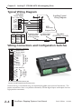
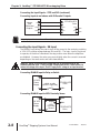
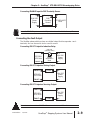
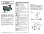
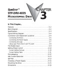
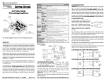
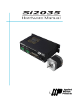
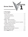
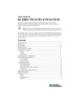
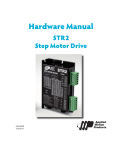
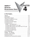
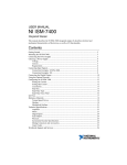
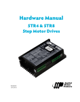
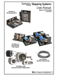
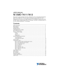
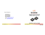
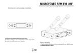
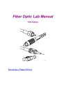
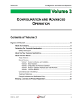
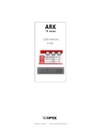
SURESTEP™
STP-DRV-6575
MICROSTEPPING DRIVE
CHAPTER
2
In This Chapter...
Features . . . . . . . . . . . . . . . . . . . . . . . . . . . . . . . . . . . . . . .2–2
Block Diagram . . . . . . . . . . . . . . . . . . . . . . . . . . . . . . . . . . .2–2
Specifications . . . . . . . . . . . . . . . . . . . . . . . . . . . . . . . . . . .2–3
Typical Wiring Diagram . . . . . . . . . . . . . . . . . . . . . . . . . . . .2–4
Wiring Connections and Configuration Switches . . . . . . . . .2–4
Connecting the Motor . . . . . . . . . . . . . . . . . . . . . . . . . . . .2–5
Connecting the Power Supply . . . . . . . . . . . . . . . . . . . . . . .2–6
Connecting the I/O . . . . . . . . . . . . . . . . . . . . . . . . . . . . . . .2–7
SureStep™ Drive Digital Inputs and Outputs . . . . . . . . . . . . . . .2–7
Connecting the Input Signals – STEP and DIR . . . . . . . . . . . . . .2–7
Connecting the Input Signals – EN Input . . . . . . . . . . . . . . . . . .2–8
Connecting the Fault Output . . . . . . . . . . . . . . . . . . . . . . . . . . .2–9
Drive Configuration . . . . . . . . . . . . . . . . . . . . . . . . . . . . . .2–10
Drive Configurations Settings . . . . . . . . . . . . . . . . . . . . . . . . . .2–10
Alarm Codes . . . . . . . . . . . . . . . . . . . . . . . . . . . . . . . . . . .2–12
Choosing a Power Supply . . . . . . . . . . . . . . . . . . . . . . . . .2–13
Mounting the Drive . . . . . . . . . . . . . . . . . . . . . . . . . . . . .2–14
Dimensions and Mounting Slot Locations . . . . . . . . . . . . .2–14
SureStepTM Stepping Systems User Manual
Chapter 2: SureStep™ STP-DRV-6575 Microstepping Drive
Specifications
SureStep™ Microstepping Drive Specifications
Part Number
STP-DRV-6575
Input Power
24–65 VDC (external power supply required; fuse at 7A fast-acting)
Output Current
0.5–7.5 A/phase (peak of sine)
Current Controller
Dual H-bridge digital MOSFET, 4-quadrant PWM at 20 kHz
Step
Input
Signals
Direction
Enable
Output
Signal
Fault
Rotary Switch Selectable
Function
Jumper
Selectable
Functions
5–24 VDC nominal (range: 4–30 VDC); (5mA @ 4V; 15 mA @ 30V);
Optically isolated, differential. Minimum pulse width = 0.5µs.
Maximum pulse frequency = 150 kHz or 2MHz (user selectable).
Function = Step or Step CW pulse.
5–24 VDC nominal (range: 4–30 VDC); (5mA @ 4V; 15 mA @ 30V);
Optically isolated, differential. Minimum pulse width = 0.5µs.
Maximum pulse frequency = 150 kHz or 2MHz (user selectable).
Function = Direction or Step CCW pulse.
5–24 VDC nominal (range: 4–30 VDC); (5mA @ 4V; 15 mA @ 30V);
Optically isolated, differential.
Function = disable motor when closed.
30 VDC / 80mA max, optically isolated photodarlington, sinking or sourcing.
Function = closes on drive fault.
Select motor based on part number, or by motor current.
Step Pulse
Type
Step and Direction: Step signal = step/pulse; Direction signal = direction.
Step CW & CCW: Step signal = CW step; Direction signal = CCW step.
Step Pulse
Noise Filter
Select 150 kHz or 2MHz
Current
Reduction
Reduce power consumption and heat generation by limiting motor running current
to 100%, 90%, or 80% of maximum. Current should be increased to 120% if
microstepping. (Torque is reduced/increased by the same %.)
Idle Current
DIP Switch Reduction
Selectable
Load Inertia
Functions
Reduce power consumption and heat generation by limiting motor idle current to
90% or 50% of running current. (Holding torque is reduced by the same %.)
Anti-resonance and damping feature improves motor
performance. Set motor and load inertia range to 0–4x or 5–10x.
Step
Resolution
For smoother motion and more precise speed, set the pulse step resolution to
20000, 12800, 5000, 2000, 400 smooth, 400, 200 smooth, or 200 steps/rev.
Self Test
Automatically rotate the motor back and forth two turns in each direction in order
to confirm that the motor is operational.
Drive Cooling Method
Natural convection (mount drive to metal surface)
Mounting
Use (2) #6 screws to mount wide or narrow side to metal surface
Removable Connectors
Motor & Power Supply: Screw term blocks Phoenix Contact 1757051 (30–12AWG)
Signals: Screw terminal blocks Phoenix Contact 1803633 (30–14 AWG)
Weight
10.8 oz [306g] – (including mating connectors)
Operating Temperature
0 to 85 °C [32 to 185 °F] – (interior of electronics section)
Ambient Temperature
0 to 50 °C [32 to 122 °F] – (drive must be mounted to suitable heat sink)
Humidity
Maximum 90% non-condensing
Agency Approvals
CE (EMC & LVD); RoHS
Fourth Edition
12/2012
SureStepTM Stepping Systems User Manual
2–3
Chapter 2: SureStep™ STP-DRV-6575 Microstepping Drive
Typical Wiring Diagram
Logic Motor
Power Power
5VDC xx VDC
Step Motor
Power Supply
SureStep Typical
Wiring Diagram
–
VDC +
+
VDC –
A+
A–
B+
STP-PWR-xxxx
B–
Cable Color Code
Term Wire Pin #
A+
Red
1
A– White
2
B+ Green 3
B– Black
4
STPDRV-xxxx
Stepper Drive
Extension Cable 12" Motor Pigtail
with Connector
with Connector
STP-EXT(H)-020
Step Motor
STP-MTR(H)-xxxxx(D)
Wiring Connections and Configuration Switches
Terminals, Switches, Indicators
Status LEDs
FAULT–
FAULT+
EN–
EN+
DIR–
DIR+
STEP–
STEP+
Removable Signal
Terminal Block
1757051
Rotary Switch
B–
B+
A–
A+
V–
V+
Removable
Power
Terminal Block
1803633
DIP Switches
Terminal block part #s (shown) are
Phoenix Contact (www.phoenixcontact.com)
External wiring is connected using two separate pluggable screw terminal connectors. The
power connections share a six-position connector, and the digital inputs and output share an
eight-position connector.
2–4
SureStepTM Stepping Systems User Manual
Fourth Edition 12/2012
Chapter 2: SureStep™ STP-DRV-6575 Microstepping Drive
Connecting the Motor
Warning: When connecting a step motor to a SureStep™ STP-DRV-6575
microstepping drive, be sure that the motor power supply is switched off. When
using a motor not supplied by AutomationDirect, secure any unused motor leads so
that they can't short out to anything. Never disconnect the motor while the drive is
powered up. Never connect motor leads to ground or to a power supply. (See the
Typical Wiring Diagram shown in this chapter for the step motor lead color code of
AutomationDirect supplied motors.)
Four lead motors
Four lead motors can only be connected one way, as shown below.
A+
A–
Red
4
lead
motor
White
Green
Black
B+
B–
4 Leads
All AutomationDirect SureStep™ motors are four lead bipolar step motors.
Six lead motors
Six lead motors can be connected in series or center tap. Motors produce more
torque at low speeds in series configuration, but cannot run as fast as in the center
tap configuration. In series operation, the motor should be operated at 30% less
than rated current to prevent overheating.
Grn/Wht
A–
n/c
A+
A–
6
lead
motor
White
A+
Green
n/c
Red
Black
B–
n/c
Red/
Wht
B+
6 Leads Series Connected
Grn/Wht
6
lead
motor
White
Green
Red
Black
B–
B+
Red/
Wht
n/c
6 Leads Center Tap Connected
Step motor wire lead colors vary from one manufacturer to another.
Fourth Edition
12/2012
SureStepTM Stepping Systems User Manual
2–5
Chapter 2: SureStep™ STP-DRV-6575 Microstepping Drive
Eight lead motors
Eight lead motors can also be connected in two ways: series or parallel. Series
operation gives you more torque at low speeds, but less torque at high speeds.
When using series connection, the motor should be operated at 30% less than the
rated current to prevent over heating. Parallel operation allows greater torque at
high speeds. When using parallel connection, the current can be increased by
40% above rated current. Care should be taken in either case to assure that the
motor does not overheat.
Orange
A+
Blk/
Wht
Orange
A+
Org/Wht
8
lead
motor
Blk/Wht
A–
8
lead
motor
Org/
Wht
A–
Black
Black
Red
Red/
Wht
B+
Yel/
Wht
Yellow
Red
Yellow
B–
B+
8 Leads Series Connected
Yel/
Wht
Red/
Wht B–
8 Leads Parallel Connected
Step motor wire lead colors vary from one manufacturer to another.
Connecting the Power Supply
An STP-PWR-xxxx power supply from AutomationDirect is the best choice to
power the step motor drive. If you need information about choosing a different
power supply, refer to the section entitled “Choosing a Power Supply” in this
chapter.
If your power supply does not have a fuse on the output or some kind of short
circuit current limiting feature, you need a fuse between the drive and the power
supply. Install the fuse on the + power supply lead.
• Connect the green ground screw to earth ground
• Use 18 or 20 AWG wire.
Fuse* EMI**
V+
V–
Step
+
Motor
VDC
Power
Supply
–
* External fuse not req'd when
using an STP-PWR-xxxx P/S; fuse is internal.
** CE use requires an EMI line filter.
Do NOT use STP-PWR-70xx power supplies with an STP-DRV-6575 drive, because
those power supplies exceed the voltage limit of this drive.
2–6
SureStepTM Stepping Systems User Manual
Fourth Edition
12/2012
Chapter 2: SureStep™ STP-DRV-6575 Microstepping Drive
Connecting the I/O
SureStep™ Drive Digital Inputs and Outputs
The SureStep STP-DRV-6575 drive includes two high-speed 5–24 VDC digital
inputs (STEP & DIR), one standard-speed 5–24 VDC digital input (EN), and one 30
VDC digital output (Fault).
Internal to the
STP-DRV-6575
STEP+
220pF
STEP–
DIR+
220pF
DIR–
EN+
The digital inputs are optically isolated to reduce
electrical noise problems. There is no electrical
connection between the control and power circuits
within the drive, and input signal communication
between the two circuits is achieved by infrared
light. Externally, the drive’s motor power and
control circuits should be supplied from separate
sources, such as from a step motor power supply
with separate power and logic outputs.
For bidirectional rotation, supply a source of step
pulses to the drive at the STEP+ and STEP–
terminals, and a directional signal at the DIR+ and
DIR– terminals.
220pF
EN–
FAULT+
FAULT–
The ENABLE input allows the logic to turn off the
current to the step motor by providing a signal to
the EN+ and EN– terminals. The EN+ and EN– terminal can be left unconnected
if the enable function is not required.
Drive Digital Input Circuit
All logic inputs can be controlled by a DC output signal that is either sinking
(NPN), sourcing (PNP), or differential.
Connecting the Input Signals – STEP and DIR
Connecting Inputs to an Indexer with Sinking Outputs
Indexer
with
Sinking
Outputs
+V OUT
DIR+
DIR
DIR–
STP-DRV-6575
Drive
STEP+
EN+
STEP–
EN–
N/C
STEP
N/C
Connecting Inputs to an Indexer with Sourcing Outputs
Indexer
with
Sourcing
Outputs
COM
DIR–
DIR
DIR+
STP-DRV-6575
Drive
STEP–
EN+
STEP+
EN–
N/C
STEP
N/C
Fourth Edition
12/2012
SureStepTM Stepping Systems User Manual
2–7
Chapter 2: SureStep™ STP-DRV-6575 Microstepping Drive
Connecting the Input Signals – STEP and DIR (continued)
Connecting Inputs to an Indexer with Differential Outputs
Indexer
with
Differential
Outputs
DIR+
DIR+
DIR–
DIR–
STP-DRV-6575
Drive
STEP+
STEP+
EN+
STEP–
STEP–
EN–
N/C
N/C
Many high speed indexers have differential (also known as line-driver) outputs.
Connecting the Input Signals – EN Input
The ENABLE input allows the user to turn off the current to the motor by providing
a 5–24 VDC positive voltage between EN+ and EN-. The logic circuitry continues
to operate, so the drive "remembers" the step position even when the amplifiers
are disabled. However, the motor may move slightly when the current is removed
depending on the exact motor and load characteristics.
Warning: 24VDC is the maximum voltage that can be applied directly to the
standard speed EN input. If using a higher voltage power source, install resistors to
reduce the voltage at the input. Do NOT apply an AC voltage to an input terminal.
Connecting ENABLE Input to Relay or Switch
+
5-24 VDC
Power
Supply
EN+
switch or relay
(closed = logic low)
-
STP-DRV-6575
Drive
EN–
Connecting ENABLE Input to NPN Proximity Sensor
+
5-24 VDC
Power
Supply
-
2–8
+
-
EN+
output
NPN
Proximity
Sensor
SureStepTM Stepping Systems User Manual
EN–
STP-DRV-6575
Drive
Fourth Edition
12/2012
Chapter 2: SureStep™ STP-DRV-6575 Microstepping Drive
Connecting ENABLE Input to PNP Proximity Sensor
+
+
5-24 VDC
Power
Supply
-
-
output
PNP
Proximity
Sensor
EN+
STP-DRV-6575
Drive
EN–
Leave the ENABLE input unconnected if you do not need to disable the amplifiers.
Connecting the Fault Output
The SureStep advanced drives have one digital output that has separate + and terminals, and can be used to sink or source current.
Connecting FAULT Output to Inductive Relay
relay coil
(inductive load)
+
FAULT+
STP-DRV6575 Drive
FAULT–
1N4935
suppression
diode
5-24 VDC
Power
Supply
-
Connecting FAULT Output as Sinking Output
FAULT+
Load
+
5-24 VDC
Power
Supply
STP-DRV6575 Drive
-
FAULT–
Connecting FAULT Output as Sourcing Output
+
FAULT+
5-24 VDC
Power
Supply
STP-DRV6575 Drive
FAULT–
Load
-
Do not connect more than 30 VDC. Current must not exceed 80 mA.
Fourth Edition
12/2012
SureStepTM Stepping Systems User Manual
2–9
Chapter 2: SureStep™ STP-DRV-6575 Microstepping Drive
Drive Configuration
You need to configure your drive for your particular application before using the
drive for the first time. The SureStep STP-DRV-6575 microstepping drive offers
several features and configuration settings, including:
Drive Configurations Settings
STP-DRV-6575 Configuration Settings
Feature
Configuration
Method
Description
Motor Phase
Select motor based on part number, or set by motor current.
Current
Rotary Switch
Mode of
Operation
(Step Pulse
Type)
Step and Direction (default):
Step signal = step/pulse; Direction signal = direction.
Step CW & CCW:
Step signal = CW step; Direction signal = CCW step.
Jumper S3
Step Pulse
Noise Filter
Select 150 kHz, or 2MHz (default)
Jumper S4
Reduce power consumption and heat generation by limiting
motor running current to 100%, 90%, or 80% of maximum.
Current should be increased to 120% if microstepping. (Torque is
reduced/increased by the same %.)
Reduce power consumption and heat generation by limiting
Idle Current
motor idle current to 90% or 50% of running current. (Holding
Reduction
torque is reduced by the same %.)
DIP Switches
Anti-resonance and damping feature improve motor performance.
Load Inertia
Set motor and load inertia range to 0–4x or 5–10x.
For smoother motion and more precise speed, set the pulse step
Step
resolution to 20000, 12800, 5000, 2000, 400 smooth, 400, 200
Resolution
smooth, or 200 steps/rev.
Automatically rotates the motor back and forth two turns in each
Self Test
direction in order to confirm that the motor is operational.
Current
Reduction
DIP Switch Settings
(Factory default = all switches OFF)
Step Resolution (steps/rev)
ON 5 6 7
20000
5 6 7
5 6 7
5 6 7
5 6 7
5 6 7
5 6 7
5 6 7
12800
5000
2000
400
SMOOTH
400
200
SMOOTH
200
Load Inertia Idle Current Reduction
Current Reduction
ON
1 2
1 2
1 2
1 2
100% 90%
80% 120%
(Use 120% when microstepping)
2–10
ON
3
3
5-10x 0-4x
SureStepTM Stepping Systems User Manual
4
ON 4
50% 90%
Self Test
ON
Fourth Edition
8
8
ON OFF
12/2012
Chapter 2: SureStep™ STP-DRV-6575 Microstepping Drive
Jumper Settings
Jumpers S3 and S4 are located on the internal circuit board, and they can be
accessed by removing the drive’s front cover.
Remove connectors and cover to access Jumpers
S3 and S4. They are located on the upper
left corner of the circuit board.
Jumper S4:
Step Pulse Noise Filter
Jumper S3:
Step Pulse Type
Jumper S3 – Step Pulse Type
• Jumper in “1-2” position – Step & Direction (factory default)
• Jumper in “1-3” position – Step CW / Step CCW
Jumper S4 – Step Pulse Noise Filter
• Jumper in “1-2” position – 2MHz
• Jumper in “1-3” position – 150 kHz (factory default)
Rotary Switch Settings – Motor/Current Settings
STP-DRV-6575 Motor Selection Table
Drive Current
(peak sine A)
Inertia
(g·cm2)
Torque
(mN·m)
Rotary Switch
Position
1.3
custom NEMA 17
3
n/a
4.0
custom NEMA 23
4
n/a
4.0
custom NEMA 34
5
-17040
1.7
61
0.28
3.03
1.60
434
51
2.04
6
-17048
2.0
83
0.37
2.65
1.40
586
82
2.40
7
-17060
2.0
125
0.56
3.30
2.00
883
37
2.40
8
-23055
2.8
166
1.46
2.36
0.08
1172
271
3.36
9
-23079
2.8
276
2.60
3.82
1.10
1949
475
3.36
A
-34066
2.8
434
7.66
7.70
1.11
3065
1402
3.36
B
H-23079
5.6
287
2.60
1.18
0.40
2025
371
6.72
C
H-34066
6.3
428
7.66
1.52
0.25
3021
1402
7.56
D
H-34097
6.3
803
14.80 2.07
0.03
5668
2708
7.56
E
H-34127
6.3
1292 21.90 4.14
0.49
9123
4008
7.56
F
12/2012
789
SureStepTM Stepping Systems User Manual
CD
AB E
n/a
456
0–2
23
Resistance
(Ω)
Inductance
(mH)
Roter Inertia
(oz·in2)
Holding
Torque (oz·in)
Motor
STP-MTR
-xxxx(D)
Motor Current
(Arms/phase)
reserved
n/a
Fourth Edition
Drive Configuration Data
F0 1
Motor Data
2–11
Chapter 2: SureStep™ STP-DRV-6575 Microstepping Drive
Alarm Codes
In the event of a drive fault or alarm, the green LED will flash one or two times,
followed by a series of red flashes. The pattern repeats until the alarm is cleared.
STP-DRV-6575 Alarm Codes
Status LED Alarm Code
Error
solid green
no alarm; motor disabled
flashing green
no alarm; motor enabled
flashing red
configuration or memory error *
1 green, 4 red
power supply voltage too high **
1 green, 5 red
over current / short circuit ** †
1 green, 6 red
open motor winding **
2 green, 3 red
internal voltage out of range **
2 green, 4 red
power supply voltage too low *
* Does not disable the motor.
The alarm will clear about 30 seconds after the fault is corrected.
** Disables the motor. Cannot be cleared until power is cycled.
† The over-current/short-circuit alarm typically indicates that an electrical fault exists
somewhere in the system external to the drive. This alarm does not serve as motor
overload protection.
2–12
SureStepTM Stepping Systems User Manual
Fourth Edition
12/2012
Chapter 2: SureStep™ STP-DRV-6575 Microstepping Drive
Choosing a Power Supply
Voltage
Chopper drives work by switching the voltage to the motor terminals on and off
while monitoring current to achieve a precise level of phase current. To do this
efficiently and silently, you'll want to have a power supply with a voltage rating at
least five times that of the motor. Depending on how fast you want to run the
motor, you may need even more voltage. Generally, more is better; the upper
limit being the maximum voltage rating of the drive itself.
If you choose an unregulated power supply, do not allow the “no load” voltage to
exceed the maximum voltage rating of the drive. Unregulated supplies are rated
at full load current. At lesser loads, such as when the motor is not moving, the
actual voltage can be up to 1.4 times the voltage list on the power supply label.
The STP-PWR-xxxx power supplies are designed to provide maximum voltage
while under load, without exceeding the drive’s upper voltage limit when
unloaded.
Use the “...Recommended Component Compatibilty” chart in the “Chapter 1:
Getting Started” to select the appropriate SureStep power supplies for use with
SureStep drives.
Current
The maximum supply current you will need is the sum of the two phase currents.
However, you will generally need a lot less than that, depending on the motor
type, voltage, speed and load conditions. That's because the SureStep drives use
switching amplifiers, converting a high voltage and low current into lower voltage
and higher current. The more the power supply voltage exceeds the motor
voltage, the less current you'll need from the power supply.
We recommend the following selection procedure:
1. If you plan to use only a few drives, choose a power supply with at least twice the
rated phase current of the motor.
2. If you are designing for mass production and must minimize cost, get one power
supply with more than twice the rated current of the motor. Install the motor in the
application and monitor the current coming out of the power supply and into the
drive at various motor loads. This test will tell you how much current you really
need so you can design in a lower cost power supply.
If you plan to use a regulated power supply, you may encounter a problem with
current foldback. When you first power up your drive, the full current of both
motor phases will be drawn for a few milliseconds while the stator field is being
established. After that, the amplifiers start chopping and much less current is
drawn from the power supply. If your power supply thinks this initial surge is a
short circuit it may "foldback" to a lower voltage. With many foldback schemes
the voltage returns to normal only after the first motor step and is fine thereafter.
In that sense, unregulated power supplies are better.
SureStep™ STP-PWR-xxxx power supplies from AutomationDirect are the best choices
of DC power supply to use with SureStep™ STP-DRV-xxxx(D) microstepping drives.
Fourth Edition
12/2012
SureStepTM Stepping Systems User Manual
2–13
Chapter 2: SureStep™ STP-DRV-6575 Microstepping Drive
Mounting the Drive
You can mount your drive on the wide or the narrow side of the chassis using (2)
#6 screws. Since the drive amplifiers generate heat, the drive should be securely
fastened to a smooth, flat metal surface that will help conduct heat away from the
chassis. If this is not possible, then forced airflow from a fan may be required to
prevent the drive from overheating.
• Never use your drive in a space where there is no air flow or where the ambient
temperature exceeds 50 °C (122 °F).
• When mouting multiple STP-DRV-xxxx drives near each other, maintain at least one
half inch of space between drives.
• Never put the drive where it can get wet.
• Never allow metal or other conductive particles near the drive.
Dimensions and Mounting Slot Locations
Dimensions = in [mm]
0.13
[3.2]
4.66
[118.4]
4.40
[111.8]
4X Ø0.14
[Ø3.6]
2.98
[75.6]
0.89
[22.7]
1.04
[26.5]
0.22
[5.6]
0.41
[10.5]
4.42
[112.3]
2 X R0.09
[R2.2]
0.35 1.30
[8.9] [33.0]
2–14
SureStepTM Stepping Systems User Manual
Fourth Edition
12/2012