1
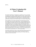
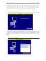
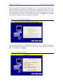
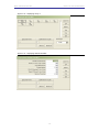
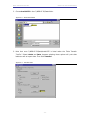
SHUTTLE BOX AVOIDANCE
MED STATE NOTATION T M PROCEDURES
SOF-700RA-7 User’s Manual
DOC-024
Rev. 2.7
Copyright © 2010
All Rights Reserved
MED Associates Inc.
P.O. Box 319
St. Albans, Vermont 05478
www.med-associates.com
MED ASSOCIATES INC.
SHUTTLE BOX AVOIDANCE
- ii -
MED ASSOCIATES INC.
SHUTTLE BOX AVOIDANCE
TABLE OF CONTENTS
Chapter 1 ...............................................................................................1
Introduction ...................................................................................................... 1
Overview of the Procedure ............................................................................... 2
References ..................................................................................................... 2
Active Avoidance (Shuttle Box Avoidance Level.mpc) ............................................ 3
Independent Variables .................................................................................. 3
Dependent Variables ..................................................................................... 4
Passive Avoidance Training & Testing (Shuttle Box Passive Avoidance Training
Level.mpc & Shuttle Box Passive Avoidance Test Level.mpc ) ................................ 4
Independent Variables .................................................................................. 4
Dependent Variables ..................................................................................... 5
Chapter 2 ...............................................................................................6
Hardware .......................................................................................................... 6
Chapter 3 ...............................................................................................7
Software ........................................................................................................... 7
Installation .................................................................................................... 7
Backing Up the Software .................................................................................. 7
Hardware Test ................................................................................................ 8
Chapter 4 ...............................................................................................9
Beginning & Running an Experiment ..................................................................... 9
Translating The MED-PC IV (.mpc) File ............................................................... 9
Using the MED-PC IV Load Wizard ................................................................... 10
Viewing/Changing Variable Values ................................................................... 15
Chapter 5 .............................................................................................17
Saving Data & Understanding the Raw Data File ................................................... 17
Chapter 6 .............................................................................................19
Data Analysis – Using MED-PC to Excel ............................................................... 19
Using a Pre-Formatted Table Profile (.MTP file) ................................................. 19
Editing the .MTP file ...................................................................................... 22
- iii -
MED ASSOCIATES INC.
SHUTTLE BOX AVOIDANCE
Chapter 7 .............................................................................................23
Modifying the Existing Program .......................................................................... 23
Introduction (Shuttle Box Avoidance Level.mpc) ................................................ 23
DESCRIPTION OF STATE SET 1 .................................................................... 23
DESCRIPTION OF STATE SET 2 .................................................................... 26
DESCRIPTION OF STATE SET 3 .................................................................... 27
DESCRIPTION OF STATE SET 4 .................................................................... 28
DESCRIPTION OF STATE SETS 5 & 6 ............................................................. 29
DESCRIPTION OF STATE SETS 7 & 8 ............................................................. 29
DESCRIPTION OF STATE SET 9 .................................................................... 30
DESCRIPTION OF STATE SETS 10 & 11 ......................................................... 30
DESCRIPTION OF STATE SETS 21-28 ............................................................ 32
DESCRIPTION OF STATE SET 32 .................................................................. 33
- iv -
MED ASSOCIATES INC.
SHUTTLE BOX AVOIDANCE
CHAPTER 1
Introduction
The latest version of MED-PC ® IV gives researchers the ability to use pre-programmed
applications such as this one to make data collection easy. These pre-programmed
applications can also be modified to meet the evolving demands of a research protocol.
This manual begins by providing step-by-step instructions on how to use this preprogrammed application. Then, the manual provides some examples of editing and
modifying the programming code, and finally it defines the elements in the raw data file
produced by this application.
In addition to this manual, refer to the MED-PC ® IV User’s Manual for the installation
of the MED-Associates interface drivers, the MED-PC IV Software, and the Delphi ®
Compiler. Also refer to the User’s Manual for instructions on hardware configuration. The
Hardware Configuration software utility accompanies MED-PC IV and is used to assign
the inputs and outputs in the interface cabinet for each task controlled by the program.
Data file structure, file-saving format, and other related options are also determined by
the Hardware Configuration software utility. Refer to the MED-PC IV Programmer’s
Manual if you are unfamiliar with the process of translating and compiling an
application.
Any lines in the .mpc file that begin with a backslash “\” are comments that help identify
key elements of the code and explain the function of each step within the program.
The staff at Med Associates, Inc. is available to answer any questions that may arise.
Please e-mail us at [email protected] with a detailed description of the
problem or your desired goals so that we may provide you with concise and detailed
information.
The Shuttle Box Avoidance procedures are designed to be as easy to use as possible.
Med Associates understands that researchers do not have the time to devote to
programming and hardware design, and for that reason, we have undertaken that burden
for you. We sincerely hope that you are satisfied with the products and services we
provide, and look forward to meeting your future experimental needs as your research
program evolves.
Thank you for purchasing Med Associates’ Instrumentation and
Software.
- 1 -
MED ASSOCIATES INC.
SHUTTLE BOX AVOIDANCE
Overview of the Procedure
The shuttle box task is a test that has been utilized to study conditioning in non-human
animals for sixty years (Miller, 1948; Mowrer & Lamoreaux, 1942; Sidman, 1960). Shuttle
box tests of avoidance and escape from aversive stimulus are used in contemporary
research (e.g. Amaropanth, LeDoux, & Nader, 2000; Caldarone et al. 2003) because
these behavioral assays are efficient and standardized methods for testing learning and
memory processes. Two types of procedures are generally used, these being active and
passive avoidance procedures.
Active avoidance is a negative reinforcement procedure (the alleviation of aversive
stimulus reinforces avoidance responding). A stimulus signals that an aversive stimulus is
imminent, and the subject learns to avoid the aversive stimulus by moving to the other
side of the two-compartment chamber after the presentation of the stimulus. The primary
dependent measure includes whether the subject (1) escapes the aversive stimulus or (2)
avoids the presentation of the aversive stimulus entirely by using the stimulus to predict
its occurrence.
Passive avoidance includes both training (conditioning) and testing phases. During
training, the subject is motivated to move to the preferred, dark portion of the twocompartment chamber. The subject is then confined to the dark portion of the chamber,
and experiences inescapable aversive stimulus. The subject is removed, and placed back
into the light portion of the chamber for testing. During testing, the subject is allowed
free access to the dark side of the chamber and the latency to move into the dark side of
the chamber is the primary dependent measure. Increased latencies to enter the dark
side of the chamber during the test are evidence. If the inescapable aversive stimulus
during the training phase was sufficient to produce conditioning, then this should be
evidenced by increased latencies to enter the dark side of the chamber during the test.
References
Amorapanth, P., LeDoux, J.E., Nader, K.(2000). Different lateral amygdala outputs
mediate reactions and actions elicited by a fear-arousing stimulus. Nature Neuroscience,
3 , 74-9.
Caldarone, B.J., Karthigeyan, K., Harrist, A., Hunsberger, J.G., Wittmack, E., King, S.L.,
Jatlow, P., Picciotto, M.R. (2003). Sex differences in response to oral amitriptyline in
three animal models of depression in C57BL/6J mice. Psychopharmacology, 170 , 94-101.
Miller, N.E. (1948). Studies of fear as an acquirable drive: I. Fear as motivation and fearreduction as reinforcement in the learning of new responses. Journal of Experimental
Psychology, 38, 89-101.
Mowrer, O.H., & Lamoreaux, R.R. (1942). Avoidance conditioning and signal duration: A
study of secondary motivation and reward. Psychological Monographs , 54.
Sidman, M. (1953). Avoidance conditioning with brief aversive stimulus and no
exteroceptive warning signal. Science , 118 , 157-8.
- 2 -
MED ASSOCIATES INC.
SHUTTLE BOX AVOIDANCE
Active Avoidance (Shuttle Box Avoidance Level.mpc)
I n d ep en de n t V a r iab l es
Trials to Run
Define the total number of trials for the session. A trial is terminated when the
subject crosses the threshold between the two chambers to avoid or escape the
aversive stimulus. Therefore, a trial consists of a CS (tone/light stimulus) and
possibly a UCS (aversive stimulus) presentation, depending on whether the subject
predicts the aversive stimulus occurrence or not. The default is 50.
Stimuli (1=tone, 2=light, 3=both)
The type of CS (conditioned stimulus) that will be utilized for avoidance conditioning.
The default value is 3.
Avoid Interval (sec)
The maximum duration of the CS (tone/light stimulus) presentation prior to the
delivery of the UCS (aversive stimulus). The default value is 5 sec.
If the CS/UCS Overlap = 0 (see below),
And the subject does not avoid the presentation of the aversive stimulus, then
the CS will terminate after 5 seconds and aversive stimulus will be administered.
However, if the subject avoids the aversive stimulus by moving to the other side
of the chamber within 2.5 sec, then the CS will terminate at 2.5 seconds and
subject will not experience the aversive stimulus.
If the CS/UCS Overlap = 1 (see below),
And the subject does not avoid the presentation of the aversive stimulus, then
the UCS (aversive stimulus) will be administered 5 seconds following the onset of
the CS (tone/light). The CS will remain on until either the subject escapes or the
Escape Interval (see below) has expired.
Escape Interval (sec)
This is the maximum duration of the UCS presentation. The default value is set to 25
seconds, but the UCS will terminate after the subject has moved to the other side of
the chamber.
CS/UCS Overlap (1=Yes, 0=No)
Enter 0 for this variable to terminate the CS (light/tone stimulus) at the onset of the
UCS (aversive stimulus). I f this variable is set to 1, then the CS and UCS will
terminate in unison.
Punish ITI Cross (1=Yes, 0=No)
Enter 1 for this variable to enable the re-administration of aversive stimulus. For
instance, if the subject avoids or escapes the aversive stimulus and then returns to
the side of chamber in which the aversive stimulus had originally occurred, the
program will re-administer aversive stimulus.
- 3 -
MED ASSOCIATES INC.
SHUTTLE BOX AVOIDANCE
Session Time (min)
Define the duration of the entire session in minutes.
Dependent Variab les
Avoids
The number of times (out of the total number of trials per session) that the subject
has moved past the threshold and avoided the delivery of aversive stimulus.
Escapes
The number of times (out of the total number of trials per session) that the subject
experiences the aversive stimulus and then moves to the other side of the chamber is
tallied under “Escapes.”
Crossings
Movement from one side of the chamber to the other is registered as a crossing.
Passive Avoidance Training & Testing (Shuttle Box Passive
Avoidance Training Level.mpc & Shuttle Box Passive Avoidance
Test Level.mpc)
I n d ep en de n t V a r iab l es
Delay to Aversive Stimulus Onset on Dark Side (sec)
This value defines the delay between when the subject enters the dark side of the
chamber and when the aversive stimulus is administered. The default value is 2
seconds.
Aversive Stimulus Duration (sec)
The duration of aversive stimulus presentation, and the default is 5 seconds
No Response Time (sec)
Conditioning has occurred once the subject fails to move into the more preferred dark
side of the chamber. The value used for “No Response Time” is thus a criterion with
which to define whether conditioning has occurred. The default is 180 seconds.
Inter-Trial Interval (sec)
The interval in between the offset of the aversive stimulus and the beginning of the
next trial. For shuttle box units with automatic guillotine doors, the opening of the
door signals the end of the Inter-Trial Interval. The default is 60 seconds
- 4 -
MED ASSOCIATES INC.
SHUTTLE BOX AVOIDANCE
Dependent Variab les
Activity
The number of I/R photobeam interruptions in the light side of the chamber is the
measure of “Activity.”
Latency (sec)
The dark side of the chamber is the more preferred side, but this is also where the
animal experiences aversive stimulus. The animal is going to be more reluctant to
move into the dark side of the chamber with increased exposure to aversive stimulus.
Thus, the “Latency” to move into the dark side of the chamber is a measure of
conditioning.
NOTE: Passive avoidance testing differs from training in that no aversive stimulus is
administered during testing. During testing, the subject should be removed after it
has moved into the dark side of the chamber. The latency to move into the dark side
of the chamber on the first trial is the most commonly used dependent measure.
- 5 -
MED ASSOCIATES INC.
SHUTTLE BOX AVOIDANCE
CHAPTER 2
Hardware
The hardware components below are included in the Deluxe Shuttle Avoidance Test
Package (manufacturer part number MED-APA-D1R).
•
•
•
•
•
•
•
•
•
•
•
ENV-010MC Shuttle Box Chamber
ENV-018V Sound Attenuating Cubicle
Photobeam Sensors
Stimulus Lights
Tone Generators
Stainless Steel Grid Floor
Automatic Guillotine Door
ENV-410 Aversive Stimulus Generator
SG-6080 Tabletop Cabinet
DIG-716B SmartCtrl Card
DIG-700F Decoder Card
Figure 2.1 - Shuttle Box Hardware
For detailed information regarding the wiring and connection of the Shuttle Avoidance
Test Package, refer to the Shuttle Box for Active & Passive Avoidance Installation
Guide.
- 6 -
MED ASSOCIATES INC.
SHUTTLE BOX AVOIDANCE
CHAPTER 3
Software
Installation
Please refer to the MED-PC IV User’s Manual for a complete guide to installing the
MED-PC IV software. The Shuttle Box Avoidance package includes a CD containing
several MED-PC testing protocols, these include:
Shuttle Box Avoidance Level.mpc
Shuttle Box Passive Avoidance Training Level.mpc
Shuttle Box Passive Avoidance Test Level.mpc
Shuttle Box Avoidance With Four Inputs Level.mpc
Shuttle Box Avoidance With Pivot Floor.mpc
Avoid.mtp (MPC2XL transfer template)
Shuttle Box Avoidance.mpc *
Shuttle Box Passive Avoidance Training.mpc *
Shuttle Box Passive Avoidance Test.mpc *
Shuttle Box Avoidance With Four Inputs.mpc *
To install these testing protocols, insert the CD into the CD-ROM drive and click Install
the Shuttle Box Software. These files will be copied to the “C:\MED-PC IV\MPC\”
folder.
*
These protocols will not be automatically copied during installation. If they are to be
used they must be manually copied to the “C:\MED-PC IV\MPC\” folder.
Backing Up the Software
Med Associates strongly encourages creating backup copies of the Shuttle Box programs
in case of disk failure. Having copies of the original programs may be useful in the future
should modifications be made to the existing programs.
- 7 -
MED ASSOCIATES INC.
SHUTTLE BOX AVOIDANCE
Hardware Test
Open the MED Test software application. Select SmartCtrl | DIG-716B/DIG-703B
from menu bar.
On the SmartCtrl (DIG-716B) display, verify that the port address is 780 and all other
values are zero. Select either Toggle P1 Bits or AutoTest to test that each output is
controlling the appropriate stimuli (lights, sound generators, grid floor, aversive stimulus
generator and door) in the shuttle box. The AutoTest option automatically progresses
through each of the outputs. Use the Toggle P1 Bits option to turn each output on and
off one at a time. If one or more of the outputs fails to properly control any of the
stimuli, verify that all of the cable connections are secure. If they are and the problem
persists, contact Med-Associates customer support for help.
The red and green LEDs on the SmartCtrl card in the interface cabinet correspond to
each of the input and output buttons on this display. When the AutoTest option is
selected, the outputs will illuminate one at a time in succession, and the appropriate
stimuli will switch on and off.
Figure 3.1 - The MED Test Display
- 8 -
MED ASSOCIATES INC.
SHUTTLE BOX AVOIDANCE
CHAPTER 4
Beginning & Running an Experiment
Translating The MED-PC IV (.mpc) File
Programs written in MedState Notation need to be translated using Trans IV before they
can be executed in this application. The MED-PC IV Programmer’s Manual explains
how to accomplish this translation. Be sure that a copy of the file being translated is
present in the directory “C:\MED-PC IV\MPC\.” Open Trans IV and select Translation |
Translate and Compile.
Select the program to use for the experiment and select Make. Click OK to start the
translator, and it should automatically parse the MedState Notation and then open to a
DOS screen to compile the Pascal code. Depending on the speed of the computer, each
of these steps may not be seen. If any problems are encountered during this process,
refer to the on-screen help menu, the MED-PC IV User’s Manual, or contact MED
Associates, Inc., for assistance.
Figure 4.1 - Trans IV Control Panel for Translating and Compiling MedState Notation Code
- 9 -
MED ASSOCIATES INC.
SHUTTLE BOX AVOIDANCE
Using the MED-PC IV Load Wizard
Open MED-PC IV and the MED-PC Experiment Loading Wizard’s Welcome screen, shown
below, will appear. To proceed with the wizard, click Next and the Box Selection screen
shown in Figure 4.3 will appear.
Figure 4.2 - The MED-PC IV Loading Wizard Welcome Screen
To avoid this load wizard, deselect the checkbox labeled Run this experiment
automatically when starting MED-PC. Close this screen by clicking the Close button.
Closing this screen immediately reveals the MED-PC Run-Time Screen shown in Figure
4.10.
- 10 -
MED ASSOCIATES INC.
SHUTTLE BOX AVOIDANCE
The Box Selection screen is the screen in which the researcher chooses which boxes will
be used in the experiment. Select the boxes that will run the experiment by clicking in
the radio button next to the box number.
The figure shows that the Hardware
Configuration included only 1 box, which was selected. Click Next to proceed.
Figure 4.3 - The Box Selection Screen
The next screen is the Select a Procedure screen. This is where the application to be run
is selected. The screen displays a list of all the currently compiled procedures. Simply
select the desired procedure, for example Shuttle Box Avoidance Level, and then click
Next.
Figure 4.4 - Select a Procedure
- 11 -
MED ASSOCIATES INC.
SHUTTLE BOX AVOIDANCE
The Enter Experiment Data screen will appear next. The purpose of this screen is to
allow annotations to be added to the data file that is produced by MED-PC IV. These
annotations will help identify the Subject, Experiment, and Experiment Group upon which
data was collected. Comments can be added here as well, and the data file can be given
a customized file name. Enter the information desired, and click Next (the information
on this panel is optional, and can be skipped if so desired).
Figure 4.5 - Enter Experiment Data Screen
The next screen to appear is the Review Choices screen. This is a method of confirming
that the information entered is correct. If it is not correct, select Previous, and edit the
data. If it is correct, select Next.
Figure 4.6 - Review Choices Screen
- 12 -
MED ASSOCIATES INC.
SHUTTLE BOX AVOIDANCE
The Alter Session Parameters Screen is the next screen to appear, and is an important
screen for the researcher. The Alter Session Parameters screen allows the researcher to
alter the parameters by which a procedure executes. Click Next to proceed.
Figure 4.7 - Alter Session Parameters Screen
The Send Start Command Screen appears next. The options available on the screen vary
depending upon how many boxes are described in the Hardware Configuration. In this
example only 1 box is described in the Hardware Configuration, so Figure 4.8 will appear
next. If more than 1 box is in the Hardware Configuration, then Figure 4.9 will appear.
Figure 4.8 - Send Start Command Screen for Single Box Configuration
- 13 -
MED ASSOCIATES INC.
SHUTTLE BOX AVOIDANCE
Figure 4.9 - Send Start Command Screen for Multiple Box Configuration
In both cases, this is where the researcher decides to either load more boxes, send a
start signal to boxes that are already loaded, or enter the MED-PC IV run-time
environment without sending a start signal by selecting I am finished with the
wizard. This option results in the screen shown in Figure 4.10.
Figure 4.10 - MED-PC IV Run Time Screen
- 14 -
MED ASSOCIATES INC.
SHUTTLE BOX AVOIDANCE
Viewing/Changing Variable Values
Before a “start command” has been issued, any variable may be changed on the MED-PC
IV run-time screen. Simply highlight the value to change, and then type in the new
value. Once a session is in progress, change variables by selecting Configure |
Change Variables on the main menu, or click the 4th tool bar item ΔX. In the lower
left hand corner of the Displaying Variables window, find the “Display Data from Box”
display, and choose the chamber(s) to modify. By clicking additional boxes in the
“Additional Boxes to Update” section, changes made to a single box are automatically
loaded on all of the boxes selected.
Figure 4.11 - Displaying Variables Screen
The value of any simple variable may be viewed from this screen. Click an array on the
table and each element in that array can be viewed. To change a value, simply highlight
and replace the value in the lower right hand box or use the up/down arrows to
increment by 1. Click the Issue button for the change to take effect. Click Named
Variables to produce the display in Figure 4.13. Change variables here as needed.
- 15 -
MED ASSOCIATES INC.
SHUTTLE BOX AVOIDANCE
Figure 4.12 - Displaying Array A
Figure 4.13 - Displaying Named Variables
- 16 -
MED ASSOCIATES INC.
SHUTTLE BOX AVOIDANCE
CHAPTER 5
Saving Data & Understanding the Raw Data File
Data is automatically saved using the filename and date created by the MED-PC IV load
wizard (Figure 4.5). Data can be saved manually by selecting File | Save Data
Manually, or File | Save Data (Flush). Unless otherwise specified, data will be saved
to C:\MED-PC IV\Data. Within each data file, the headings are created for each Subject,
Experiment, Group, Box, etc., (see below). Data files may be opened with note pad, word
pad, or any word processor or spreadsheet; however, make sure they are always saved
“unformatted” in case you would ever want to use a data extraction utility such as MEDPC to Excel. Data file formats are explained in detail in the MED-PC IV User’s Manual.
File: C\MED-PC IV\DATA\!2005-02-18
Start Date: 02/14/2008
End Date: 02/14/2008
Subject: 1
Experiment: PHASE 1
Group: Hippocampal 1a
Box: 1
Start Time: 9:43:05
End Time: 10:40:16
MSN: Shuttle Box Avoidance Level
C:
E:
F:
G:
H:
I:
J:
K:
L:
M:
N:
O:
P:
Q:
R:
T:
U:
V:
W:
X:
Y:
Z:
0.00
113.0
0.00
0.00
0.00
40.00
0.00
0.00
1.00
0.00
0.00
0.00
0.00
0.00
0.00
0.00
0.00
0.00
0.00
1350
0.00
0.00
Session identification information
that was entered during the load
wizard, see Figure 4.5.
E = Elapsed Time in seconds.
I = Subscript for data array D (see
below).
L = Animal Location Flag
X = The current ITI drawn from List
S (S = List of ITI times from 7.5
- 22.5 seconds, with a mean 15
seconds, see below for S array).
- 17 -
MED ASSOCIATES INC.
SHUTTLE BOX AVOIDANCE
A:
0:
5.00
3.00
5:
1.00
6.00
500.00
2500.00
Named Variables Array:
1.00
Trials to run = 5; Stimuli = 3; Avoid
Interval = 5sec; Escape Interval =
25sec; CS/UCS Overlap = 1; Punish
ITI Cross = 1; Session Time = 6min.
B:
3.45
3.00
9.80
Summary Data Array:
102.00 52.00 10.00
5.00
0.00
Avoids, Escapes, Crossings
0:
5:
5.00
2.00
D( ) = Trial by Trial Data
(I)
D:
0:
1.00
0.00
0.00
1.00 12.20
D(I)
5:
0.00 24.00
1.00
0.00
0.00
D(I+1) = Avoid
2.00
1.00
4.50
0.00
0.00
D(I+2) = Avoid Latency
15: 27.00
1.00
1.00
0.00
0.00
D(I+3) = Escape
20:
3.00
0.00
0.00
1.00
8.70
D(I+4) = Escape Latency
25: 45.00
4.00
2.00
1.00
0.00
30:
0.00
0.00
1.00
8.50
35: 19.00 19.00
3.00
2.00
0.00
40:
1.00
2.40
0.00
0.00
45: 11.00 11.00
4.00
3.00
0.00
10:
4.00
5.00
= Trial Number
D(I+5) = Left Movement Activity
D(I+6) = Right Movement Activity
D(I+7) = Crossings
D(I+8) = ITI Aversive Stimuli
D(I+9) = RESERVED
S() = List of ITI times
S:
0: 750.0
5: 1500.0
900.0
1650.0
1050.0
1800.0
1200.0 1350.0
1950.0 2100.0
These numbers appear in
“MED time units,” 1 sec =
100 MED time units (given a
resolution setting of 10 ms).
10: 2250.0
\Session 7
7.5 - 22.5 seconds (mean of
15 sec)
“Comments,” see Figure 4.5.
- 18 -
MED ASSOCIATES INC.
SHUTTLE BOX AVOIDANCE
CHAPTER 6
Data Analysis – Using MED-PC to Excel
Using a Pre-Formatted Table Profile (.MTP file)
MED-PC to Excel (MPC2XL) is a program that helps to import data from MED-PC (the rawdata file format, previous section) to a spreadsheet program such as Microsoft Excel TM .
MPC2XL needs to be installed separately from MED-PC IV. Please refer to the User’s
Manual for MPC2XL for installation instructions. Follow the step-by-step instructions
below for importing data obtained from the shuttle box .mpc procedures.
1. Open Microsoft Excel, and then minimize the window. Open MED-PC to Excel. The
MED-PC to Excel display (see Figure 6.1) will appear. The leftmost file tab is titled
Transfer Data, shown in the figure below. In the Table Transfer window at the
bottom of the screen, click Select.
Figure 6.1 - Table Transfer
- 19 -
MED ASSOCIATES INC.
SHUTTLE BOX AVOIDANCE
2. Choose Avoid.MTP in the C:\MED-PC IV\Data folder.
Figure 6.2 - Select Avoid.MTP
3. Note that now C:\MED-PC-IV\Data\Avoid.MTP is listed under the Table Transfer
“Profile.” Select Labels and Data, because selecting these options will print data
labels as well as import data. Then click Transfer!.
Figure 6.3 - Transfer Data
- 20 -
MED ASSOCIATES INC.
SHUTTLE BOX AVOIDANCE
4. Specify the raw data file to transfer, and then click Open. This step performs the
transfer, and now the data has been sent to Microsoft Excel.
Figure 6.4 - Specify Data Files to Transfer
5. Expand the Microsoft Excel screen, and the data should appear in the following
format:
Figure 6.5 - Excel Spreadsheet
- 21 -
MED ASSOCIATES INC.
SHUTTLE BOX AVOIDANCE
Editing the .MTP file
The .MTP file can be edited to customize the transfer process and display the data of
most interest. See the User’s Manual for MPC2XL for explicit instructions about how to
modify the MTP file using the “Edit Table Profiles” screen, see Figure 6.6. “Header Titles”
are user defined, and can include any information that will help label the data listed
below the title. “Header Elements” are the data points that will get transferred from the
raw data file into Excel. The raw data file will list the elements that can be included in
the .MTP file (e.g. A-Z).
Figure 6.6 - Edit Table Profiles
To edit either the Header Titles or Header Elements, click on the appropriate cell in the
Edit Table Profiles window. Rows and columns can be added to the file. First, select the
desired location, then right-click to add either the desired row or column. Use the rightclick option titled Paste an Identifier to include subject or session identifying
information. Note that when using the Paste an Identifier function, Header Titles and
Header Elements are edited and pasted automatically.
To save the edited .MTP file, select Save and create a new filename under the C:\MEDPC IV\Data folder. To use this newly edited and saved .MTP file, verify that the file is
selected in the Table Transfer Profile display (Figure 6.3), and then click Transfer.
- 22 -
MED ASSOCIATES INC.
SHUTTLE BOX AVOIDANCE
CHAPTER 7
Modifying the Existing Program
Introduction (Shuttle Box Avoidance Level.mpc)
The Shuttle Box Avoidance procedure was written to run standard shuttle avoidance for a
specified number of trials (default = 50). Each trial produces a printout (optional) and
data entry with the trial number, avoid tag, 1 = avoid, 0 = no avoid, avoid latency to the
nearest 0.1 seconds, escape tag, escape latency, left activity, right activity, crossings,
and ITI aversive stimuli. Shuttle Box Avoidance Level.mpc is listed below in its entirety
followed by a brief explanation of each state set.
See the MED-PC IV User’s Manual for details regarding the processing of commands in
MED-PC. The MED-PC IV Programmer’s Manual and online tutorial provides necessary
information on Med-State Notation, and these resources will be very helpful when making
adjustments to Shuttle Box Avoidance Level.mpc, or creating a custom .mpc program.
Shuttle Box Avoidance Level.mpc
\ Copyright (C) 2010 MED Associates, All Rights Reserved.
\
\
\
\
\
\
\
\
\
\
\
Shuttle Box Avoidance Level
For systems with 8 I/R Photobeam sensors, separate Left and Right Light and Tone,
and either with or without Auto-Guillotine Door. The default values used for
this Procedure run a fixed number of 50 Trials. Each Trial presents both
stimuli for 5 seconds followed by a maximum 25 second shock escape interval while
the stimuli remain on. The mean ITI interval is 15 seconds. The total session
time is set at 60 minutes, however, given the above parameters the test will
always end in less than an hour.
Program runs only in Level Mode.
\ The #1 Beam is the Beam Closest to the Door or Hurdle on each Side.
\ Inputs are Assigned from Left to Right as viewed from front of Box.
\ Inputs
^LeftIR_4
^LeftIR_3
^LeftIR_2
^LeftIR_1
^RightIR_1
^RightIR_2
^RightIR_3
^RightIR_4
=
=
=
=
=
=
=
=
\ Outputs
^LeftLight
^RightLight
^LeftTone
^RightTone
^Door
^ShockOperate
^LeftGrid
^RightGrid
1
2
3
4
5
6
7
8
=
=
=
=
=
=
=
=
1
2
3
4
5
6
7
8
\ Control Variables with Assigned Aliases as Defined
- 23 -
MED ASSOCIATES INC.
Var_Alias
Var_Alias
Var_Alias
Var_Alias
Var_Alias
Var_Alias
Var_Alias
SHUTTLE BOX AVOIDANCE
Number of Trials to Run
Stimuli (1=Tone 2=Lgt 3=Both)
Avoid Interval (sec)
Escape Interval
CS/UCS Overlap (1=Yes 0=No)
Punish ITI Cross (1=Yes 0=No)
Session Time (min)
=
=
=
=
=
=
=
A(0)
A(1)
A(2)
A(3)
A(4)
A(5)
A(6)
\
\
\
\
\
\
\
Default
Default
Default
Default
Default
Default
Default
=
=
=
=
=
=
=
50
Both
5 seconds
25 seconds
Yes
Yes
60 minutes
\ Subscript Constants for Control Variables
^Trials
= 0
^StimTag
= 1
^CS_Time
= 2
^UCS_Time
= 3
^OverlapTag = 4
^ITIShockTag = 5
^SessionTime = 6
\ List Data Variables Here
\ B() = Summary Data Array
\ Subscript Constants for Summary Data Array
^TrialCount
= 0 \ Total Trials Run
^TotalAvoids
= 1
^AvoidLatency
= 2 \ Divided by Total Avoids for Mean Latency
^TotalEscapes
= 3
^EscapeLatency = 4 \ Divided by Total Escapes for Mean Latency
^LeftMovement
= 5
^RightMovement = 6
^TotalCrossings = 7
^TotalITIShocks = 8
\ B(9) = Not Used
\
\
\
\
\
\
\
\
\
\
\
D() = Trial by Trial Data Array
D(I)
= Trial Number
D(I+1) = Avoid Tag
D(I+2) = Avoid Latency
D(I+3) = Escape Tag
D(I+4) = Escape Latency
D(I+5) = Left Movement Activity
D(I+6) = Right Movement Activity
D(I+7) = Crossings
D(I+8) = ITI Shocks
D(I+9) = RESERVED
\ List Working Variables Here
\ E = Elapsed Time in Seconds
\ I = Subscript for Data Array D
\ L = Location Flag (1 = Left, 2 = Right)
\ S() = List of ITI times 7.5 - 22.5 seconds (mean 15 seconds)
\
This list may be edited as needed. These numbers appear
\
in MED time units, i.e. 1 second = 100 MED Ticks given
\
a Resolution setting of 10 ms
\ X = Trial ITI Drawn from List S
\ Z-Pulses Used in This
^Start_CS
= 1
\ Z1
^Avoid
= 2
\ Z2
^Escape
= 3
\ Z3
^Start_ITI = 4
\ Z4
^EnterLeft = 5
\ Z5
^EnterRight = 6
\ Z6
^End_CS
= 7
\ Z7
^EndSession = 8
\ Z8
^One
= 21 \ Z21
^Two
= 22 \ Z22
^Three
= 23 \ Z23
^Four
= 24 \ Z24
Procedure
= Signal Start of CS
= Signal Avoid
= Signal Escape
= Signal Start of ITI
= Entrance to Left Compartment (must break beam 2 - 4)
= Entrance to Right Compartment
= Signal no CS/UCS Overlap (Stim Off)
= End of Session
= Beam 1 Break
= Beam 2 Break
= Beam 3 Break
= Beam 4 Break
- 24 -
MED ASSOCIATES INC.
^Five
^Six
^Seven
^Eight
=
=
=
=
25
26
27
28
\
\
\
\
Z25
Z26
Z27
Z28
SHUTTLE BOX AVOIDANCE
=
=
=
=
Beam
Beam
Beam
Beam
5
6
7
8
Break
Break
Break
Break
\ Dimension Array Sizes
DIM A = 6
\ Named Variables
DIM B = 9
\ Summary Data Array
DIM D = 6000 \ Trial Data Array
\ Available ITI Intervals. Mean 15 Seconds.
LIST S = 7.5", 9", 10.5", 12", 13.5", 15", 16.5", 18", 19.5", 21", 22.5"
DISKCOLUMNS = 10
DISKFORMAT = 6.2
D ES C RIP TION O F S TA T E S ET 1
State Set 1 is the core of program and sets the default values for all independent
variables (S1), programs the load wizard setup application (S2), starts the procedure on
animal entry (S3), ends the session (S4 & S5), repeats each trial (S6), and saves the
data (S10-12).
\***************************************************
\
Shuttle Box Avoidance Level Schedule
\ S1 - Set Default Values
\
Number of Trials to Run
(50)
\
Stimuli
(Light & Tone)
\
Avoid Interval
(5 seconds)
\
Escape Interval
(25 seconds)
\
CS/UCS Overlap
(Yes)
\
Punish ITI Cross
(Yes)
\
Session Time
(60 minutes)
\***************************************************
S.S.1, \ Setup, Adaptation & ITI Interval Timers
S1,
0.001": SET A(^Trials)
= 50, A(^StimTag)
= 3, A(^CS_Time)
= 5;
SET A(^UCS_Time)
= 25, A(^OverlapTag) = 1, A(^ITIShockTag) = 1;
SET A(^SessionTime) = 60 ---> S2
S2,
#START: SET A(^CS_Time)
= A(^CS_Time) * 1";
SET A(^UCS_Time)
= A(^UCS_Time) * 1";
SET B(^TrialCount) = 1;
SET D(I)
= B(^TrialCount);
SET D(I+10)
= -987.987;
RANDD X = S; ON ^Door; Z^Start_CS ---> S3
1": SHOW 1,Trials,A(^Trials),
2,Stimulus,A(^StimTag),
3,Avoid
Time,A(^CS_Time);
SHOW 4,Escape Time,A(^UCS_Time), 5,CS/UCS Overlap,A(^OverlapTag), 6,ITI
Shock,A(^ITIShockTag);
SHOW 7,Session Time,A(^SessionTime) ---> SX
S3,
\ Verify Detection of Animal
0.01": IF (L = 1) OR (L = 2) [@StartNow, @Wait]
@Start: Z^Start_CS ---> S4
@Wait: ---> SX
S4,
\ Wait for End of Trial
#Z^Avoid ! #Z^Escape ! #Z^Start_ITI: ---> S5
S5,
\ Time ITI Interval. End Session following completion of
\ ITI if Session Time or Number of Trials completed is
\ equal to or greater than the set values.
X#T: IF (E/60 >= A(^SessionTime)) OR (B(^TrialCount) >= A(^Trials)) [@EndSession,
@NewTrial]
@End: Z^EndSession ---> S10
@New: ---> S6
S6,
\ Set up new Trial
0.01": ADD B(^TrialCount); SET I = I + 10;
SET D(I) = B(^TrialCount), D(I+10) = -987.987;
- 25 -
MED ASSOCIATES INC.
SHUTTLE BOX AVOIDANCE
SHOW 1,Trial #,D(I); RANDD X = S; Z^Start_CS ---> S4
S10,
\ End of Session Calculations - Check for Zero Avoids
0.01": IF B(^TotalAvoids) = 0 [@True, @False]
@True: ---> S11
@False: SET B(^AvoidLatency) = B(^AvoidLatency) / B(^TotalAvoids) ---> S11
S11,
\ Check for Zero Escapes
0.01": IF B(^TotalEscapes) = 0 [@True, @False]
@True: ---> S12
@False: SET B(^EscapeLatency) = B(^EscapeLatency) / B(^TotalEscapes) ---> S12
S12,
\ Delay for Screen Update
2": OFF ^Door ---> STOPABORTFLUSH
D ES C RIP TION O F S TA T E S ET 2
State Set 2 tracks the location of the animal in the chamber (S1-S3).
\*********************************************
\
TRACK ANIMAL LOCATION
\*********************************************
S.S.2, \ Set Location Flag L and issue Location Z-Pulse
S1,
#R^LeftIR_1 ! #R^LeftIR_2 ! #R^LeftIR_3 ! #R^LeftIR_4: SET L = 1 ---> S2
#R^RightIR_1 ! #R^RightIR_2 ! #R^RightIR_3 ! #R^RightIR_4: SET L = 2 ---> S4
S2,
\ Animal on Left Grid, wait for Beam break on Right Side
#R^RightIR_1 ! #R^RightIR_2 ! #R^RightIR_3 ! #R^RightIR_4: ---> S3
#Z^EndSession:
---> S6
S3,
\ Check to see if any Left Side Beams are being broken, if not then
\ count it as a crossing to the Right Side.
#R^LeftIR_4 ! #R^LeftIR_3 ! #R^LeftIR_2 ! #R^LeftIR_1: ---> S2
0.02": SET L = 2; Z^EnterRight
---> S4
#Z^EndSession:
---> S6
S4,
\ Animal on Right Grid, wait for Beam break on Left Side
#R^LeftIR_1 ! #R^LeftIR_2 ! #R^LeftIR_3 ! #R^LeftIR_4: ---> S5
#Z^EndSession:
---> S6
S5,
\ Check to see if any Right Side Beams are being broken, if not then
\ count it as a crossing to the Left Side.
#R^RightIR_1 ! #R^RightIR_2 ! #R^RightIR_3 ! #R^RightIR_4: ---> S4
0.02": SET L = 1; Z^EnterLeft
---> S2
#Z^EndSession:
---> S6
S6,
\ Holding State at End of Session
1': ---> SX
- 26 -
MED ASSOCIATES INC.
SHUTTLE BOX AVOIDANCE
D ES C RIP TION O F S TA T E S ET 3
State Set 3 controls the trial sequence for when the subject starts the trial on the left
(S1, S5-S8) and right (S10-S13) side of the chamber.
\*********************************************
\
TRIAL SEQUENCE AND DATA COLLECTION
\*********************************************
S.S.3,
S1,
\ Initiate Trials
#Z^Start_CS: IF L = 1 [@LeftTrial, @Next]
@LeftTrial: ---> S5
@Next: IF L = 2 [@RightTrial, @Error]
@RightTrial: ---> S10
@Error:
---> SX
S5,
\ Trial Sequence Starting from Left Chamber - CS Period
A(^CS_Time)#T: ON ^LeftGrid;
IF A(^OverLapTag) >= 1 [@OverLap, @NoOverLap]
@OverLap: ---> S6
@NoOverLap: Z^End_CS ---> S6
#Z^EnterRight: ADD D(I+1), B(^TotalAvoids);
ADD D(I+7), B(^TotalCrossings);
Z^Avoid; Z^End_CS ---> S1
S6,
\ Activate Shock - Left Side
0.01": ON ^ShockOperate ---> S7
#Z^EnterRight: ADD D(I+1), B(^TotalAvoids);
ADD D(I+7), B(^TotalCrossings);
Z^Avoid; Z^End_CS ---> S1 \ Process Avoid from S5 if it occurs
\ on same interrupt as CS timeout.
S7,
\ UCS Period - Left Chamber
A(^UCS_Time)#T: OFF ^ShockOperate, ^LeftGrid;
Z^Start_ITI; Z^End_CS ---> S1
#Z^EnterRight: ADD D(I+3), B(^TotalEscapes);
ADD D(I+7), B(^TotalCrossings);
Z^Escape; Z^End_CS ---> S8
S8,
\ Shock OFF Delay to Force a Complete Crossing
1.5": OFF ^ShockOperate, ^LeftGrid ---> S1
\-----------------------------------------------------\ S10 - S13 are identical in function to S5 - S8 Above
\-----------------------------------------------------S10,
\ Trial Sequence Starting from Right Chamber - CS Period
A(^CS_Time)#T: ON ^RightGrid;
IF A(^OverLapTag) >= 1 [@OverLap, @NoOverLap]
@OverLap: ---> S11
@NoOverLap: Z^End_CS ---> S11
#Z^EnterLeft: ADD D(I+1), B(^TotalAvoids);
ADD D(I+7), B(^TotalCrossings);
Z^Avoid; Z^End_CS ---> S1
S11,
\ Activate Shock - Right Side
0.01": ON ^ShockOperate ---> S12
#Z^EnterLeft: ADD D(I+1), B(^TotalAvoids);
ADD D(I+7), B(^TotalCrossings);
Z^Avoid; Z^End_CS ---> S1
S12,
\ UCS Period - Right Chamber
A(^UCS_Time)#T: OFF ^ShockOperate, ^RightGrid;
Z^Start_ITI; Z^End_CS ---> S1
#Z^EnterLeft: ADD D(I+3), B(^TotalEscapes);
ADD D(I+7), B(^TotalCrossings);
Z^Escape; Z^End_CS ---> S13
S13,
\ Shock OFF Delay to Force a Complete Crossing
1.5": OFF ^ShockOperate, ^RightGrid ---> S1
- 27 -
MED ASSOCIATES INC.
SHUTTLE BOX AVOIDANCE
D ES C RIP TION O F S TA T E S ET 4
State Set 4 establishes the operation of the ITI punishment procedure. If “Crossings” are
being punished, and once the ITI has initiated (S2), the aversive stimulus sequence
begins (S3). The maximum duration of aversive stimulus is defined in S5. If ITI crossing
are not punished, then the sequence begins at S10.
\*********************************************
\
PUNISH ITI CROSSINGS
\*********************************************
S.S.4, \ 0.5" Shocks if Activated
S1,
#START: ---> S2
S2,
\ Wait for Start of ITI
#Z^Avoid ! #Z^Escape ! #Z^Start_ITI: IF A(^ITIShockTag) = 1 [@PunishCrossing, @NoShock]
@Punish: ---> S3
@NoShock: ---> S10
S3,
\ Start of Sequence with Shock - Wait for Crossing
#Z^EndSession: ---> S1
#Z^EnterLeft ! #Z^EnterRight: ADD D(I+7), B(^TotalCrossings);
ADD D(I+8), B(^TotalITIShocks);
IF L = 1 [@Left, @Right]
@Left: ON ^LeftGrid ---> S4
@Right: ON ^RightGrid ---> S4
#Z^Start_CS: ---> S2 \ End of ITI
S4,
0.01": ON ^ShockOperate ---> S5
#Z^EndSession: OFF ^LeftGrid, ^RightGrid ---> S1
#Z^Start_CS:
OFF ^LeftGrid, ^RightGrid ---> S2
S5,
0.5":
OFF ^ShockOperate, ^LeftGrid, ^RightGrid ---> S6
#Z^EndSession: OFF ^ShockOperate, ^LeftGrid, ^RightGrid ---> S1
#Z^Start_CS:
OFF ^ShockOperate, ^LeftGrid, ^RightGrid ---> S2
S6,
0.5":
---> S3
#Z^EndSession: ---> S1
#Z^Start_CS:
---> S2
\ Punishment Recovery Period
S10,
\ Start of Sequence with no Shock - Wait for Crossing
#Z^EndSession: ---> S1
#Z^EnterLeft ! #Z^EnterRight: ADD D(I+7), B(^TotalCrossings) ---> S11
#Z^Start_CS: ---> S2 \ End of ITI
S11,
\ Time Delay to Match the with Shock Sequence
1.01":
---> S10
#Z^EndSession: ---> S1
#Z^Start_CS:
---> S2
- 28 -
MED ASSOCIATES INC.
SHUTTLE BOX AVOIDANCE
D ES C RIP TION O F S TA T E S ET S 5 & 6
State Set 5 calculates the response latency variables and prints the information in the
data file (array D). State Set 6 prints the summary information to the MED-PC Run-Time
Screen.
\*********************************************
\
RESPONSE LATENCY DETERMINATION
\*********************************************
S.S.5,
S1,
#Z^Start_CS: ---> S2
S2,
#Z^Avoid: SET B(^AvoidLatency) = B(^AvoidLatency) + D(I+2), D(I+4) = 0 ---> S1
#Z^Escape: SET B(^EscapeLatency) = B(^EscapeLatency) + D(I+4), D(I+2) = 0 ---> S1
#Z^Start_ITI: SET D(I+2) = 0, D(I+4) = 0 ---> S1 \ No Response
0.01": SET D(I+2) = D(I+2) + 0.01;
\ Avoid Latency
SET D(I+4) = D(I+4) + 0.01 ---> SX
\ Escape Latency
\*********************************************
\
SHOW TRIAL # AND SUMMARY DATA
\*********************************************
S.S.6,
S1,
#START: CLEAR 1,60 ---> S2
S2,
1": SHOW 1,Trial #,B(^TrialCount),
2,Avoids,B(^TotalAvoids);
SHOW 3,Escapes,B(^TotalEscapes),
4,Crossings,B(^TotalCrossings);
SHOW 9,ITI Shocks,B(^TotalITIShocks), 11,Left Movement,B(^LeftMovement);
SHOW 16,Right Movement,B(^RightMovement) ---> SX
#Z^EndSession: ---> S1
D ES C RIP TION O F S TA T E S ET S 7 & 8
State Sets 7 and 8 print avoid and escape latency data to the Run-Time Screen.
\*********************************************
\
SHOW MEAN AVOID LATENCY
\*********************************************
S.S.7,
S1,
#START: ---> S2
S2,
1": IF B(^TotalAvoids) >= 1 [] ---> S3
S3,
1": SHOW 7,Avoid Latency,B(^AvoidLatency)/B(^TotalAvoids) ---> SX
#Z^EndSession: ---> S1
\*********************************************
\
SHOW MEAN ESCAPE LATENCY
\*********************************************
S.S.8,
S1,
#START: ---> S2
S2,
1": IF B(^TotalEscapes) >= 1 [] ---> S3
S3,
1": SHOW 8,Escape Latency,B(^EscapeLatency)/B(^TotalEscapes) ---> SX
#Z^EndSession: ---> S1
- 29 -
MED ASSOCIATES INC.
SHUTTLE BOX AVOIDANCE
D ES C RIP TION O F S TA T E S ET 9
State Set 9 operates the tone and light stimuli. Whether the tone (1), the light (2), or
both stimuli (3) function to promote avoidance are defined in the experimental load
wizard (Figure 4.7). S6 waits for either the escape/avoid response or the end of the
escape interval to turn off the stimuli.
\*********************************************
\
STIMULUS CONTROL
\*********************************************
S.S.9,
S1,
#START: ---> S2
S2,
0.01": IF A(^StimTag) = 1 [@Tone, @Next]
@Tone: ---> S3
@Next: IF A(^StimTag) = 2 [@Light, @Next]
@Light: ---> S4
@Next: IF A(^StimTag) = 3 [@Both, @NoStim]
@Both:
---> S5
@NoStim: ---> S1
S3,
\ Tone Only
#Z^Start_CS: IF L = 1 [@Left, @Right]
@Left: ON ^LeftTone ---> S6
@Right: ON ^RightTone ---> S6
S4,
\ Light Only
#Z^Start_CS: IF L = 1 [@Left, @Right]
@Left: ON ^LeftLight ---> S6
@Right: ON ^RightLight ---> S6
S5,
\ Both Tone & Light
#Z^Start_CS: IF L = 1 [@Left, @Right]
@Left: ON ^LeftTone, ^LeftLight ---> S6
@Right: ON ^RightTone, ^RightLight ---> S6
S6,
\ Wait for Signal to turn Stimuli OFF
#Z^End_CS: OFF ^LeftTone, ^LeftLight;
OFF ^RightTone, ^RightLight ---> S2
D ES C RIP TION O F S TA T E S ET S 1 0 & 1 1
State Sets 10 and 11 record left and right movement within the chamber, respectively.
\*********************************************
\
LEFT MOVEMENT ACTIVITY
\*********************************************
S.S.10,
S1,
#START: ---> S2
S2,
\ Wait for Start of First Trial
#Z^Start_CS: ---> S3
S3,
\
#Z^Four:
#Z^Three:
#Z^Two:
#Z^One:
Wait
--->
--->
--->
--->
for first Beam Break
S4
S5
S6
S7
S4,
\ Movement following a Beam 1 Break
#Z^EndSession:
--->
#Z^Three: ADD B(^LeftMovement), D(I+5) --->
#Z^Two:
ADD B(^LeftMovement), D(I+5) --->
#Z^One:
ADD B(^LeftMovement), D(I+5) --->
S1
S5
S6
S7
S5,
\ Movement following a Beam 2 Break
#Z^EndSession:
--->
#Z^Four: ADD B(^LeftMovement), D(I+5) --->
#Z^Two:
ADD B(^LeftMovement), D(I+5) --->
#Z^One:
ADD B(^LeftMovement), D(I+5) --->
S1
S4
S6
S7
- 30 -
MED ASSOCIATES INC.
SHUTTLE BOX AVOIDANCE
S6,
\ Movement following a Beam 3 Break
#Z^EndSession:
--->
#Z^Four: ADD B(^LeftMovement), D(I+5) --->
#Z^Three: ADD B(^LeftMovement), D(I+5) --->
#Z^One:
ADD B(^LeftMovement), D(I+5) --->
S1
S4
S5
S7
S7,
\ Movement following a Beam 4 Break
#Z^EndSession:
--->
#Z^Four: ADD B(^LeftMovement), D(I+5) --->
#Z^Three: ADD B(^LeftMovement), D(I+5) --->
#Z^Two:
ADD B(^LeftMovement), D(I+5) --->
S1
S4
S5
S6
\*********************************************
\
RIGHT MOVEMENT ACTIVITY
\*********************************************
S.S.11,
S1,
#START: ---> S2
S2,
\ Wait for Start of First Trial
#Z^Start_CS: ---> S3
S3,
\
#Z^Five:
#Z^Six:
#Z^Seven:
#Z^Eight:
Wait
--->
--->
--->
--->
for first Beam Break
S4
S5
S6
S7
S4,
\ Movement following a Beam 1 Break
#Z^EndSession:
--->
#Z^Six:
ADD B(^RightMovement), D(I+6) --->
#Z^Seven: ADD B(^RightMovement), D(I+6) --->
#Z^Eight: ADD B(^RightMovement), D(I+6) --->
S1
S5
S6
S7
S5,
\ Movement following a Beam 2 Break
#Z^EndSession:
--->
#Z^Five: ADD B(^RightMovement), D(I+6) --->
#Z^Seven: ADD B(^RightMovement), D(I+6) --->
#Z^Eight: ADD B(^RightMovement), D(I+6) --->
S1
S4
S6
S7
S6,
\ Movement following a Beam 3 Break
#Z^EndSession:
--->
#Z^Five: ADD B(^RightMovement), D(I+6) --->
#Z^Six:
ADD B(^RightMovement), D(I+6) --->
#Z^Eight: ADD B(^RightMovement), D(I+6) --->
S1
S4
S5
S7
S7,
\ Movement following a Beam 4 Break
#Z^EndSession:
--->
#Z^Five: ADD B(^RightMovement), D(I+6) --->
#Z^Six:
ADD B(^RightMovement), D(I+6) --->
#Z^Seven: ADD B(^RightMovement), D(I+6) --->
S1
S4
S5
S6
- 31 -
MED ASSOCIATES INC.
SHUTTLE BOX AVOIDANCE
D ES C RIP TION O F S TA T E S ET S 2 1 - 2 8
State Sets 21-28 record the IR inputs for each Beam exactly like Toggle Mode records
inputs.
\*********************************************
\
BEAM 1 BREAK
\*********************************************
S.S.21,
S1,
#START: ---> S2
S2,
#R^LeftIR_4: Z^One ---> S3
S3,
#R^LeftIR_4: ---> SX
0.01":
---> S2
\*********************************************
\
BEAM 2 BREAK
\*********************************************
S.S.22,
S1,
#START: ---> S2
S2,
#R^LeftIR_3: Z^Two ---> S3
S3,
#R^LeftIR_3: ---> SX
0.01":
---> S2
\*********************************************
\
BEAM 3 BREAK
\*********************************************
S.S.23,
S1,
#START: ---> S2
S2,
#R^LeftIR_2: Z^Three ---> S3
S3,
#R^LeftIR_2: ---> SX
0.01":
---> S2
\*********************************************
\
BEAM 4 BREAK
\*********************************************
S.S.24,
S1,
#START: ---> S2
S2,
#R^LeftIR_1: Z^Four ---> S3
S3,
#R^LeftIR_1: ---> SX
0.01":
---> S2
\*********************************************
\
BEAM 5 BREAK
\*********************************************
S.S.25,
S1,
#START: ---> S2
S2,
#R^RightIR_1: Z^Five ---> S3
S3,
#R^RightIR_1: ---> SX
- 32 -
MED ASSOCIATES INC.
0.01":
SHUTTLE BOX AVOIDANCE
---> S2
\*********************************************
\
BEAM 6 BREAK
\*********************************************
S.S.26,
S1,
#START: ---> S2
S2,
#R^RightIR_2: Z^Six ---> S3
S3,
#R^RightIR_2: ---> SX
0.01":
---> S2
\*********************************************
\
BEAM 7 BREAK
\*********************************************
S.S.27,
S1,
#START: ---> S2
S2,
#R^RightIR_3: Z^Seven ---> S3
S3,
#R^RightIR_3: ---> SX
0.01":
---> S2
\*********************************************
\
BEAM 8 BREAK
\*********************************************
S.S.28,
S1,
#START: ---> S2
S2,
#R^RightIR_4: Z^Eight ---> S3
S3,
#R^RightIR_4: ---> SX
0.01":
---> S2
D ES C RIP TION O F S TA T E S ET 32
State Set 32 counts the time for the session.
\*********************************************
\
SESSION TEST TIMER
\*********************************************
S.S.32,
S1,
#START: SHOW 5,Elapsed Time,E/60 ---> S2
S2,
\ Wait for Start of First Trial
#Z^Start_CS: ---> S3
S3,
\ Increment and Display time only.
\ Session End is not triggered in S.S.1, S5
\ until Current Trial is completed.
1": ADD E; SHOW 5,Elapsed Time,E/60 ---> SX
#Z^EndSession: ---> S1
- 33 -


![60 (3) Change any myss[i] calls, where myss is a loop iteration, to](http://vs1.manualzilla.com/store/data/005660192_1-8eea2c3cfc95064c732d161dbe3c262f-150x150.png)