1
®
LinePrinter Plus® for Line Matrix Printers
Programmer’s Reference Manual
LinePrinter Plus® for Line Matrix Printers
Programmer’s Reference Manual
®
Printronix, Inc. makes no representations or warranties of any kind regarding
this material, including, but not limited to, implied warranties of
merchantability and fitness for a particular purpose. Printronix, Inc. shall not
be held responsible for errors contained herein or any omissions from this
material or for any damages, whether direct, indirect, incidental or
consequential, in connection with the furnishing, distribution, performance or
use of this material. The information in this manual is subject to change
without notice.
This document contains proprietary information protected by copyright. No
part of this document may be reproduced, copied, translated or incorporated
in any other material in any form or by any means, whether manual, graphic,
electronic, mechanical or otherwise, without the prior written consent of
Printronix, Inc.
COPYRIGHT © 2007, 2010, PRINTRONIX, INC.
All rights reserved.
Trademark Acknowledgements
IBM and Proprinter are registered trademarks of the International Business
Machines Corp.
IGP, LinePrinter Plus, PGL and Printronix are registered trademarks of
Printronix, Inc.
Code V is a trademark of Quality Micro Systems, Inc.
HP is a registered trademark of Hewlett-Packard Company.
Epson is a registered trademark of Seiko Epson Corporation.
Dataproducts is a registered trademark of Dataproducts Corporation.
Centronics is a registered trademark of Genicom Corporation.
This product uses Intellifont Scalable typefaces and Intellifont technology.
Intellifont is a registered trademark of Agfa Division, Miles Incorporated
(Agfa).
CG, Garth Graphic, Intellifont, and Type Director are registered trademarks,
and Shannon and CG Triumvirate are trademarks of Agfa Division, Miles
Incorporated (Agfa). CG Bodoni, CG Century Schoolbook, CG Goudy Old
Style, CG Melliza, Microstyle, CG Omega, and CG Palacio are products of
Agfa Corporation. CG Times, based on Times New Roman under license
from The Monotype Corporation Plc is a product of Agfa.
Univers is a registered trademark of Linotype AG and/or its subsidiaries.
Letraset is a registered trademark, and Aachen, Revue and University Roman
are trademarks of Esselte Pendaflex Corporation.
Futura is a registered trademark of Fundición Tipográfica Neufville, S.A.
ITC Avant Garde Gothic, ITC Benguiat, ITC Bookman, ITC Century, ITC
Cheltenham, ITC Clearface, ITC Galliard, ITC Korinna, ITC Lubalin Graph,
ITC Souvenir, ITC Tiepolo, ITC Zapf Chancery, and ITC Zapf Dingbats are
registered trademarks of International Typeface Corporation.
Albertus, Gill Sans, and Times New Roman are registered trademarks, and
Monotype Baskerville is a trademark of The Monotype Corporation Plc,
registered in the U.S. Pat. and TM office and elsewhere.
Hiroshige and Marigold are trademarks of AlphaOmega Typography, Inc.
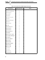
Table of Contents
1 Introduction ........................................................... 17
About This Manual..................................................................................17
Warnings And Special Information ...................................................18
2 IBM Proprinter III XL Emulation ............................ 19
Overview.................................................................................................19
Proprinter III XL Emulation Default Settings.....................................20
Configuring The Proprinter III XL Emulation With Control Codes...........22
Format For Control Code Descriptions.............................................22
Escape Control Codes Overview .....................................................22
Graphics Control Codes Overview ...................................................23
The Control Codes ...........................................................................25
Backspace........................................................................................27
Bell ...................................................................................................27
Bit Image Mode, Single Density (Normal Speed).............................28
Bit Image Mode, Double Density (Half Speed).................................29
Bit Image Mode, Double Density (Normal Speed) ...........................30
Bit Image Mode, Quadruple Density (Half Speed) ...........................31
Bold Printing .....................................................................................32
Bold Printing, Cancel........................................................................32
Cancel ..............................................................................................32
Carriage Return................................................................................33
Carriage Return Set .........................................................................33
Character Pitch 12 cpi ......................................................................34
Character Set Select: Set 1 (A) ........................................................34
Character Set Select: Set 2 (B) ........................................................34
Condensed Print ..............................................................................35
Condensed Print Cancel ..................................................................36
Deselect Printer................................................................................36
Double Wide Print ............................................................................36
Double Wide Print (One Line Only) ..................................................38
Double Wide Print (One Line Only) Cancel......................................38
Emphasized Print .............................................................................39
Emphasized Print Cancel .................................................................39
Form Feed........................................................................................40
Forms Length Set in Inches .............................................................40
7
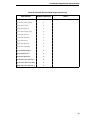
Table of Contents
Forms Length Set in Lines ...............................................................41
Initialize Parameters......................................................................... 42
Line Feed .........................................................................................44
Line Feed n/216 Inch (One Line Only) ............................................. 45
Line Spacing 1/8 Inch (8 lpi)............................................................. 46
Line Spacing 7/72 Inch (10.3 lpi)...................................................... 46
Line Spacing n/72 Inch (Executes) ..................................................47
Line Spacing n/72 Inch (Storage)..................................................... 48
Line Spacing n/216 Inch................................................................... 49
Margin, Bottom ................................................................................. 49
Margin, Bottom (Cancel) .................................................................. 50
Margins, Horizontal .......................................................................... 50
Overscoring ...................................................................................... 51
Print All Characters .......................................................................... 51
Print Next Character......................................................................... 52
Print Mode ........................................................................................ 52
Print Quality...................................................................................... 53
Proportional Spacing........................................................................ 53
Select Attributes ............................................................................... 54
Superscript/Subscript Printing.......................................................... 55
Superscript/Subscript Printing, Cancel............................................. 56
Super-Set Commands...................................................................... 56
Set Top-of-Form ............................................................................... 56
Tab, Horizontal ................................................................................. 57
Tab Set/Clear, Horizontal ................................................................. 57
Tab, Vertical ..................................................................................... 58
Tab Set/Clear, Vertical .....................................................................59
Tabs, Clear All (Return to default).................................................... 60
Underline.......................................................................................... 60
Unidirectional Printing ...................................................................... 60
3 Epson FX-1050 Emulation .................................... 61
Overview................................................................................................. 61
Default Values And States ...............................................................62
Epson Emulation Exceptions And Differences ................................. 64
Epson Character Sets ...................................................................... 65
Configuring The Epson FX-1050 Emulation With Control Codes ...........66
Format For Control Code Descriptions ............................................ 66
Escape Sequences .......................................................................... 66
Set And Reset Codes....................................................................... 67
NUL Code ........................................................................................ 67
Print Modes Supported For Character Sets .....................................67
8
Table of Contents
The Control Codes ...........................................................................70
Backspace........................................................................................72
Bell ...................................................................................................73
Cancel Line ......................................................................................73
Carriage Return................................................................................73
Character Pitch 10 CPI ....................................................................73
Character Pitch 12 CPI ....................................................................74
Character Pitch 15 CPI ....................................................................74
Character Set Select: International Languages................................74
Clear Bit 7 of Incoming Data Bytes to 0 ...........................................76
Condensed Print ..............................................................................76
Condensed Print Reset ....................................................................77
Cut-Sheet / Paper Feed Control.......................................................77
Define a Download Character ..........................................................77
Delete Character ..............................................................................78
Double High Print, Set/Reset ...........................................................78
Double Strike....................................................................................79
Double Strike, Cancel ......................................................................79
Double Wide Print ............................................................................80
Double Wide Print (1 Line) ...............................................................81
Double Wide Print (1 Line), Cancel ..................................................81
Emphasized Print .............................................................................82
Emphasized Print, Cancel ................................................................82
Enable Printing Hex Codes 00-1F and 80-9F ..................................83
Form Feed........................................................................................83
Graphics, Standard Density .............................................................85
Graphics, Double Density.................................................................86
Graphics, Double Density Double Speed.........................................87
Graphics, Quadruple Density ...........................................................88
Half Speed Mode, On/Off .................................................................88
Horizontal Tab Execute ....................................................................89
Horizontal Tab Set/Release .............................................................89
Initialize Printer.................................................................................90
Italic Printing.....................................................................................90
Italic Printing, Cancel .......................................................................90
Line Feed .........................................................................................91
Line Feed n/216 Inch .......................................................................91
Line Spacing 1/6 Inch (6 lpi).............................................................92
Line Spacing 1/8 Inch (8 lpi).............................................................92
Line Spacing 7/72 Inch.....................................................................93
Line Spacing n/216 Inch...................................................................93
Line Spacing n/72 Inch.....................................................................94
9
Table of Contents
Make Hex 80-9F Control Codes....................................................... 94
Make Hex 80-9F Printable ...............................................................94
Master Print Select ........................................................................... 96
Paper Out Detection, Enable ........................................................... 96
Paper Out Detection, Disable........................................................... 96
Pass Bit 7 from Host ........................................................................ 97
Printer Select.................................................................................... 97
Printer Deselect................................................................................ 97
Reassign Graphics Mode................................................................. 97
Remove Downloaded Characters .................................................... 98
Reverse Line Spacing n/216 Inch .................................................... 98
Select Graphics Mode...................................................................... 99
Select Italic Character Set................................................................ 99
Select 9-Pin Graphics Mode .......................................................... 100
Select Print Quality......................................................................... 100
Select/Deselect Proportional Spacing ............................................ 101
Select Serif or Sans Serif Font....................................................... 101
Select User-Defined Font............................................................... 101
Select Vertical Tab Channel........................................................... 101
Set Absolute Horizontal Print Position in 1/60 Inch ........................ 102
Set Bit 7 of Incoming Data Bytes to 1 ............................................ 102
Set Relative Horizontal Print Position in 1/120 Inch ....................... 102
Set Intercharacter Spacing in 1/120 Inch ....................................... 102
Set Margin, Left.............................................................................. 103
Set Margin, Right ........................................................................... 103
Set Forms Length by Lines ............................................................ 104
Set Form Length in Inches .............................................................104
Set Vertical Tabs in Channels ........................................................ 105
Skip Over Perforation..................................................................... 105
Skip Over Perforation, Cancel........................................................ 106
Superscript/Subscript Printing........................................................ 106
Superscript/Subscript Printing, Cancel........................................... 107
Super-Set Commands.................................................................... 107
Underline........................................................................................ 107
Unidirectional Printing, 1 Line ........................................................ 108
Unidirectional Printing, Set/Reset .................................................. 108
Vertical Tab, Execute ..................................................................... 108
Vertical Tab, Set/Clear ...................................................................109
10
Table of Contents
4 P-Series Printer Emulation.................................. 111
Overview...............................................................................................111
P-Series Default Values And States...............................................112
Configuring The P-Series Emulation With Control Codes ....................114
Format For Control Code Descriptions...........................................114
Special Function Control Code (SFCC) Header.............................115
The Control Codes .........................................................................119
Backspace......................................................................................121
Bell .................................................................................................121
Bold Print........................................................................................122
Bold Print Reset .............................................................................122
Carriage Return..............................................................................123
Character Set Select ......................................................................124
Characters 80-9F (Control Codes) .................................................126
Characters 80-9F (Printable Symbols) ...........................................126
Character Set Select: ECMA 94 Latin 1 Extended.........................127
Character Set Select: International Languages..............................128
Elongated (Double High) Print, 1 Line Only ...................................129
Elongated (Double High) Print, Set/Reset......................................130
Emphasized Print ...........................................................................131
Emphasized Print Reset.................................................................131
Emulation Reset .............................................................................132
Expanded Print (Double Wide).......................................................132
Expanded Print (Double Wide), 1 Line Only...................................133
Extended Character Set .................................................................133
Extended Character Set Cancel (Primary Set Select)....................134
Form Feed......................................................................................134
Forms Length Set (Inches).............................................................134
Forms Length Set (Lines)...............................................................135
Line Feed .......................................................................................135
Line Spacing 1/6 Inch (6 lpi)...........................................................136
Line Spacing 1/8 Inch (8 lpi)...........................................................136
Line Spacing 8 or 10.3 lpi (1 Line Only) .........................................137
Line Spacing 7/72 Inch...................................................................137
Line Spacing n/72 Inch...................................................................138
Line Spacing n/216 Inch.................................................................139
Overscoring ....................................................................................140
Plot, Even Dot (P-Series High Density Graphics) ..........................140
Plot, Odd Dot (P-Series Normal Density Graphics)........................140
Print Mode/Pitch Selection .............................................................141
Reverse ..........................................................................................143
Select Attributes .............................................................................144
11
Table of Contents
Superscript/Subscript Printing........................................................ 145
Superscript/Subscript Printing Reset ............................................. 146
Super-Set Commands.................................................................... 146
Underline........................................................................................ 147
VFU Commands (P-Series) ........................................................... 147
Vertical Tab .................................................................................... 147
5 Serial Matrix Printer Emulation............................ 149
Overview............................................................................................... 149
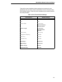
Serial Matrix Default Values And States ........................................ 150
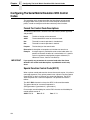
Configuring The Serial Matrix Emulation With Control Codes .............. 152
Format For Control Code Descriptions .......................................... 152
Special Function Control Code (SFCC) ......................................... 152
Attribute Set And Reset Codes ......................................................153
NUL Code ...................................................................................... 153
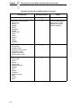
Print Modes Supported For Character Sets ...................................153
The Control Codes ......................................................................... 156
Backspace...................................................................................... 158
Bell ................................................................................................. 158
Bit Image Mode, Single Density ..................................................... 159
Bit Image Mode, Double Density.................................................... 160
Bit Image Mode, Double Density Double Speed ............................ 161
Bit Image Mode, Quadruple Density .............................................. 162
Bold Print Set ................................................................................. 163
Bold Print Reset ............................................................................. 163
Cancel ............................................................................................ 164
Carriage Return.............................................................................. 164
Character Pitch 10 CPI .................................................................. 165
Character Pitch 12 CPI .................................................................. 165
Character Set Select ...................................................................... 165
Characters 80-9F (Control Codes) ................................................. 167
Characters 80-9F (Printable Symbols) ........................................... 167
Characters 80-9F (Printable Symbols) ........................................... 168
Character Set Select: International Languages .............................168
Condensed Print ............................................................................ 169
Condensed Print Reset .................................................................. 170
Delete .............................................................................................170
Elongated (Double High) Print (One Line Only) .............................170
Elongated (Double High) Print, Set/Reset...................................... 171
Emphasized Print ........................................................................... 171
Emphasized Print Reset................................................................. 172
Emulation Reset............................................................................. 172
12
Table of Contents
Expanded (Double Wide) Print.......................................................173
Expanded (Double Wide) Print (One Line Only) ............................173
Extended Character Set ................................................................174
Extended Character Set Cancel (Primary Character Set Select)...174
Form Feed......................................................................................175
Forms Length Set (Inches).............................................................175
Forms Length Set (Lines)...............................................................176
Horizontal Tab ................................................................................176
Horizontal Tab Set .........................................................................177
Line Feed .......................................................................................177
Line Feed n/216 Inch (One Line Only) ...........................................178
Line Spacing 1/6 Inch (6 lpi)...........................................................179
Line Spacing 1/8 Inch (8 lpi)...........................................................179
Line Spacing 7/72 Inch...................................................................180
Line Spacing n/72 Inch...................................................................181
Line Spacing n/216 Inch.................................................................182
Overscoring ....................................................................................182
Print Mode/Pitch Selection .............................................................183
Printer Select..................................................................................185
Printer Deselect..............................................................................185
Reverse ..........................................................................................185
Skip-Over Perforation.....................................................................186
Skip-Over Perforation Cancel.........................................................186
Superscript/Subscript Printing ........................................................187
Superscript/Subscript Printing Reset..............................................187
Super-Set Commands....................................................................188
Underline ........................................................................................188
Vertical Tab ....................................................................................189
Vertical Tab, Set/Clear ...................................................................190
6 P-Series XQ Variant Printer Emulation ............... 191
Overview...............................................................................................191
P-Series XQ Variant Default Values And States ............................192
Configuring The XQ Variant Emulation With Control Codes ................194
Format For Control Code Descriptions...........................................194
Edit Mode .......................................................................................195
NUL Code ......................................................................................195
The Control Codes .........................................................................196
Alternate Character Set Deselect (Shift In) ....................................197
Alternate Character Set Select (Shift Out) .....................................197
Carriage Return..............................................................................198
Compressed Print ..........................................................................199
13
Table of Contents
Delete .............................................................................................200
Electronic Vertical Format Unit (EVFU).......................................... 200
Elongated Characters (Double High Print) ..................................... 201
Form Feed...................................................................................... 201
Line Feed .......................................................................................202
Line Spacing (8 or 10.3 LPI) .......................................................... 202
Plot, Even Dot (P-Series XQ High Density Graphics) .................... 203
Plot, Odd Dot (P-Series XQ Normal Density Graphics) ................. 203
Select Draft Print ............................................................................ 204
Space .............................................................................................204
Underline........................................................................................ 205
Vertical Tab .................................................................................... 205
7 Super-Set Programming ..................................... 207
Introduction ........................................................................................... 207
Using The Super-Set Commands......................................................... 207
Character Sets ............................................................................... 208
Character Set Selection (UTF8) ..................................................... 211
Character Spacing n/240 Inch........................................................ 211
Font Selection ................................................................................211
TrueType Font Selection ................................................................ 216
Line Spacing n/288 Inch................................................................. 216
Printer Protocol Select ...................................................................217
Barcodes............................................................................................... 218
Barcode Format ............................................................................. 220
Codabar ......................................................................................... 224
Code 39.......................................................................................... 226
Code 93.......................................................................................... 228
Code 128........................................................................................ 230
EAN 8 .............................................................................................234
EAN 13........................................................................................... 235
FIM ................................................................................................. 236
Intelligent Mail 4-State Barcode ..................................................... 238
Interleaved 2/5 (I-2/5) and German I-2/5........................................ 239
MSI................................................................................................. 240
PDF 417 ......................................................................................... 241
PostBar and Royal Mail.................................................................. 243
POSTNET ...................................................................................... 244
Telepen .......................................................................................... 246
UCC/EAN-128 ................................................................................247
UPC-A ............................................................................................ 252
UPC-E ............................................................................................ 253
14
Table of Contents
UPC Shipping.................................................................................256
UPS 11 ...........................................................................................257
8 Graphics.............................................................. 259
Overview...............................................................................................259
Bit Image Graphics ...............................................................................259
Designing A Bit Image Pattern .......................................................261
Bit Image Density ...........................................................................261
Plot Mode..............................................................................................264
Plot Density ....................................................................................264
Plot Data Byte Format ....................................................................265
Plot Data Line Format ....................................................................266
Plotting The Data ...........................................................................269
Exiting From P-Series/P-Series XQ Variant Plot Mode..................270
Combining Graphics And Text..............................................................270
Plot Data Byte Dot Patterns ...........................................................271
9 Vertical Page Formatting .................................... 273
Overview...............................................................................................273
Planning A Vertical Page Format..........................................................273
VFU Characteristics .......................................................................274
Vertical Tab Table For Proprinter, Epson, And Serial Matrix................274
Executing Vertical Tabs .................................................................274
Vertical Tab Positions ....................................................................275
EVFU For P-Series And P-Series XQ Variant Emulations ...................276
Start Load Code - Hex 1E Or 6E....................................................276
Channel Assignment ......................................................................276
End Load - Hex 1F Or 6F ...............................................................277
Using The EVFU ............................................................................277
Clearing The EVFU Memory ..........................................................279
Relative Line Slewing .....................................................................280
DVFU: Dataproducts Direct Access Vertical Format Unit.....................282
Start Load Code - Hex 6C, 6D, Or 6E ............................................282
Channel Assignments ....................................................................282
End Load Code - Hex 6F ...............................................................282
Using The DVFU ............................................................................283
Clearing The DVFU Memory ..........................................................283
Relative Line Slewing .....................................................................284
CVFU: Centronics Vertical Format Unit ................................................286
Start Load Code - Hex 1D ..............................................................286
Channel Assignments ....................................................................286
End Load Code - Hex 1E ...............................................................287
Using The CVFU - Hex 1F .............................................................287
15
Table of Contents
Clearing The CVFU Memory .......................................................... 288
Relative Line Slewing..................................................................... 289
10 Downloading Characters ..................................... 291
Downloading Characters (P-Series And Serial Matrix Only) ................291
Procedure.......................................................................................292
Examples .......................................................................................296
Downloaded Fonts And Character Sets ......................................... 303
Download A Character Set Overlay......................................................305
A ASCII Character Set............................................ 309
B PTX_SETUP Option............................................ 311
Overview............................................................................................... 311
The PTX_SETUP Commands .............................................................. 311
Commands ..................................................................................... 312
C Character Library ................................................ 317
D Glossary .............................................................. 323
E Contact Information............................................. 337
Printronix Customer Support Center..................................................... 337
Printronix Supplies Department ............................................................ 337
Corporate Offices.................................................................................. 338
16
1
Introduction
About This Manual
This manual is designed so that you can quickly find the information you need
to program the LinePrinter Plus® emulations provided with your printer. The
following five LinePrinter Plus emulations (or protocols) are provided as part
of the default configuration for your printer:
•
•
•
•
•
IBM® Proprinter® III XL emulation
Epson® FX-1050 emulation
Printronix® P-Series emulation
Serial Matrix emulation
Printronix P-Series XQ Variant emulation
Each emulation may be configured and programmed by sending emulation
control codes from an attached host computer to the printer. The control
codes for each emulation are described in this book. You may also configure
many parameters using the printer's control panel, as described in the User's
Manual.
Brief descriptions follow for each chapter in this book:
Chapter 1, “Introduction.” Provides an overview of this book, printer
features, and line matrix printing technology.
Chapter 2, “IBM Proprinter III XL Emulation.” Describes the Proprinter XL
control code commands that you can send to the printer through the host data
stream. These commands allow you to send instructions to the printer and
configure many Proprinter III XL emulation parameters.
Chapter 3, “Epson FX-1050 Emulation.” Explains the Epson control code
commands that you can send to the printer through the host data stream.
These commands allow you to send instructions to the printer and configure
many Epson FX emulation parameters.
Chapter 4, “P-Series Printer Emulation.” Covers the P-Series control code
commands that you can send to the printer through the host data stream.
These commands allow you to send instructions to the printer and configure
many P-Series emulation parameters.
Chapter 5, “Serial Matrix Printer Emulation.” Describes the Serial Matrix
control code commands that you can send to the printer through the host data
stream. These commands allow you to send instructions to the printer and
configure many Serial Matrix emulation parameters.
17
Chapter
1
About This Manual
Chapter 6, “P-Series XQ Printer Emulation.” Covers the P-Series XQ
Variant control code commands that you can send to the printer through the
host data stream. These commands allow you to send instructions to the
printer and configure many XQ emulation parameters.
Chapter 7, “Super-Set Programming.” Describes the super-set commands
that are available to enhance the LinePrinter Plus emulations. The superset
commands allow you to select character sets and draw barcodes.
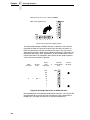
Chapter 8, “Graphics.” Information about bit image graphics printing and
programming. Descriptions are provided for designing a bit image pattern,
using control codes to set bit image density, and issuing commands for bit
image programming. A bit image sample program is included.
Chapter 9, “Vertical Page Formatting.” Information on programming and
using vertical format unit (VFU) programs that regulate vertical paper
movement and vertical tabs for printing forms.
Chapter 10, “Downloading Characters.” Information on saving, restoring,
and deleting downloaded characters and character sets.
Warnings And Special Information
Read and comply with all information highlighted under special headings:
WARNING
CAUTION
IMPORTANT
Conditions that could harm you as well as damage the equipment.
Conditions that could damage the printer or related equipment.
Information vital to proper operation of the printer.
NOTE: Information affecting printer operation.
18
2
IBM Proprinter III XL
Emulation
Overview
This chapter describes the Proprinter III XL emulation host control codes.
“Emulation” refers to the ability of a printer to execute the commands of a
particular printer control language. A printer control language is the coding
system used to convey, manipulate, and print data. It contains character
codes and command sequences that configure the emulation. In this manual,
the terms “emulation,” “printer protocol,” and “printer control language” are
synonymous.
In the Proprinter III XL emulation mode, your printer can print files coded for
the Proprinter III XL printer control language. To select the Proprinter
emulation as the active printer emulation, select LinePrinter+ from the
EMULATION menu and Proprinter III XL from the Printer Protocol menu, as
described in the User's Manual.
The Proprinter III XL emulation provides many configurable parameters. The
default parameter values for this emulation are shown in Table 1. You can
modify these parameter values in two ways:
•
The Proprinter III XL host control codes. An extensive set of Proprinter
III XL control code commands can be sent to the printer from an attached
host computer via the host data stream. Most of this chapter is devoted to
describing the Proprinter III XL control code commands.
•
The printer configuration menus. You can modify a subset of the
Proprinter III XL emulation parameters using the printer configuration
menus, control panel keys, and LCD, as described in the User's Manual.
Control codes sent from a host system generally override previous settings
that result from the configuration menus.
NOTE: Configuration values selected from the menus or via host control
codes can be saved to the printer's NVRAM memory so that they will
not be lost when you power off the printer or reset it to the factory
default configuration. The menu selection for saving a configuration to
memory is described in the User's Manual. Refer to Appendix B,
“PTX_SETUP Option” to save the configuration using host control
codes.
19
Chapter
2
Overview
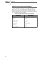
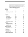
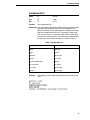
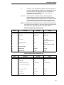
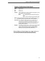
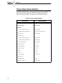
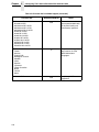
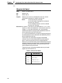
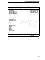
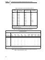
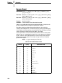
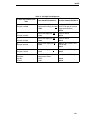
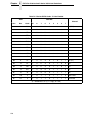
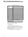
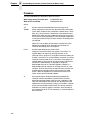
Proprinter III XL Emulation Default Settings
The factory settings for the Proprinter III XL emulation menu options are
shown in Table 1. Table 2 lists additional factory settings for parameters
provided by the LinePrinter+ formatting menus. (The EMULATION menu
options are described in the User's Manual). Host control codes can override
many of the settings for these menu options.
Table 1. Proprinter III XL Menu Option Factory Settings
Characteristic
20
Default Setting
Define CR Code
CR = CR
Auto LF
Enable
Define LF Code
LF = LF
FF Valid at TOF
Enable
Character Set
Code Page 437
Alt. Char Set
Set 1
20 CPI Condensed
Enable
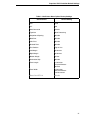
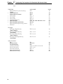
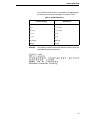
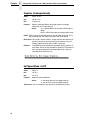
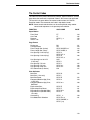
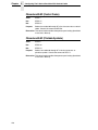
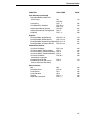
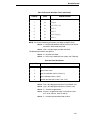
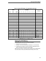
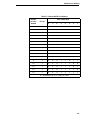
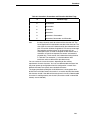
Proprinter III XL Emulation Default Settings
Table 2. LinePrinter+ Menu Option Factory Settings
Characteristic
Default Setting
CPI
10.0
LPI
6.0
Host Command
Enable
Typeface
Data Processing
Proportional Spacing
Disable
Bold Print
Disable
Italic Print
Disable
Slashed Zero
Disable
Text Position
Top of Line
Left Margin
0 columns
Right Margin
0 columns
Bottom Margin
0 lines
Perforation Skip
Disable
Form Length
11.0 inches
279.4 millimeters
66 lines
Form Width
13.6 inches
345.4 millimeters
136 characters
Reset Cmd CFG Ld
Disable
21
Chapter
2
Configuring The Proprinter III XL Emulation With Control Codes
Configuring The Proprinter III XL Emulation With Control
Codes
The remainder of this chapter describes the Proprinter printer control
language codes that may be sent from a host computer attached to the
printer, in order to configure numerous Proprinter III XL emulation
parameters.
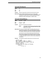
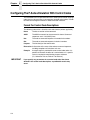
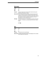
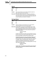
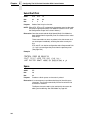
Format For Control Code Descriptions
In this chapter, the following information is listed for each control code (where
applicable):
Name
The title or function of the command.
ASCII Code The ASCII mnemonic for the command is shown. Command
sequences are in 7-bit (ASCII) form.
Hex Code
The code or command sequence in hexadecimal numbers.
Dec Code
The code or command sequence in decimal numbers.
Purpose
The function(s) of the control code.
Discussion A discussion of the uses of the code or command sequence,
including exceptions or limitations to its use.
Example
A sample is provided when it is possible to illustrate the effect of
a control code or if a specific syntax is required.
NOTE: If you specify any parameters for a control code other than the ones
that are defined in the control code description, unpredictable results
may occur. The PI line is never recognized in Proprinter III XL
Emulation mode.
Escape Control Codes Overview
Printer capability is greatly increased by the use of escape control code
sequences. Escape sequences always begin with the ASCII escape
sequence introducer, ESC (hex 1B). Many of the ASCII control codes
described in this chapter are escape sequences.
IMPORTANT
An Escape code can occur anywhere in the datastream and is acted
upon immediately if it precedes a valid command.
An ESC sequence introducer in the data stream signals the printer to wait for
special instructions, even if it is ready and printing. The character codes
following the ESC character tell the printer what to do.
NOTE: For readability, code sequences appear in this manual with spaces
inserted between command elements. Do not insert spaces between
code characters when you are programming unless the ASCII space
character (SP) is part of a code sequence. For example, a code
sequence printed in this manual as ESC [ 1 is programmed as ESC[1.
22
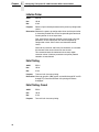
Graphics Control Codes Overview
An escape sequence uses two or more bytes to define a specific printer
control function. The format for an escape sequence is:
ASCII
ESC
X
n
Hex
1B
00-7F
0-FF
Escape Sequence
Introducer
Character(s)
Numerical
parameter(s)
After the ESC character are one or more characters which indicate the action
of the control code. One or more numerical parameters may in turn follow
these characters. For example, the sequence ESC S n tells the printer to
begin the superscript print attribute if n is an even number, or to begin the
subscript attribute if n is an odd number.
If the characters following the ESC code are not within the defined ranges, or
if they are within the defined ranges but not recognized as a function of this
printer, the entire sequence is ignored.
Graphics Control Codes Overview
The individual control codes that set graphics print quality are described
starting on page 25. Some additional background information about graphics
printing for the Proprinter III XL emulation is provided here.
The Proprinter III XL emulation provides one data protocol for printing
graphics information; the Bit Image graphics protocol allows an image block to
be printed. When using the Bit Image protocol, you can mix text and graphics
on the same line.
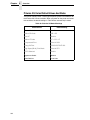
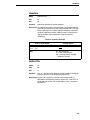
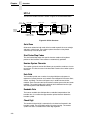
Setting Bit Image Modes via Control Codes
Control codes select bit image modes. The following bit image modes can be
mixed on the same line as text characters:
Table 3. Bit Image Modes
Control Code
Bit Image Mode
ESC K n1 n2 data
Normal Density
ESC L n1 n2 data
Double Density
ESC Y n1 n2 data
Double Density, Double Speed
ESC Z n1 n2 data
Quadruple Density
Parameters n1 and n2 together represent a 16-bit (hexadecimal) unsigned
number of the quantity (n1 + 256n2), which equals the number of bit image
characters (i.e. data bytes) to follow. If n1 and n2 are programmed so that
data extends past the last character position, the data is truncated at the last
character position. If n1 and n2 are both zero, the ESC sequence is ignored.
See Chapter 8 for details on bit image graphics.
23
Chapter
2
Configuring The Proprinter III XL Emulation With Control Codes
Dot Density Versus Printing Speed
When you select ESC K (normal density), the dot columns are printed at 60
dots per inch (dpi) horizontally and 72 dpi vertically. This does not decrease
printing speed.
If ESC L (double density) is selected, the dot columns are printed at 120 dpi
horizontally and 72 dpi vertically. Double density reduces printing speed by
one half.
With ESC Y (double density, double speed), dot columns are printed at 120
dpi horizontally and 72 dpi vertically, but adjacent dots are not printed. Double
density, double speed does not decrease printing speed.
When ESC Z (quadruple density) is selected, the dot columns are printed at
240 dpi horizontally and 72 dpi vertically. Quadruple density reduces printing
speed by one half.
All line-by-line character print attributes are ignored in Bit Image graphics. The
most significant bit for each data character is the uppermost dot position in the
vertical dot image pattern. A bit value of 1 indicates a dot; a value of 0
indicates a blank. In 7-bit RS-232E serial interface protocol, the most
significant bit (bit 8) is cleared to 0.
Code Page and Character Set Control Codes
A code page is a set of symbols consisting of letters, numbers, and graphic
elements. For the Proprinter III XL emulation, your printer supports characters
from IBM's Code Page 0437 and Code Page 0850, among an extensive array
of different print quality and print language sets. The print language sets are
selected using the Print Language configuration menu option, which is
described in detail in your User's Manual.
Two columns of characters, hex 80 through 9F, may be configured as either
control codes or printable symbols. Control code ESC 7 selects Character Set
1 (hex 80-9F configured as control codes). Control code ESC 6 selects
Character Set 2 (hex 80-9F configured as printable symbols).
Ignored Codes
The control codes recognized by the Proprinter III XL emulation software are
described in this chapter. Control codes not described in this chapter are
undefined and ignored. In addition, codes that represent printable characters
(hex 10, 11, 15, 21-7E, and 80-FF) are not available as Proprinter III XL
control codes.
NOTE: Entering control codes that are not defined in this chapter may
produce unpredictable results.
The ASCII control code ETX (hex code 03 or 1B 03) is ignored as a Proprinter
III XL control code, but is valid for the Serial Interface Protocol.
Reserved Codes
The Download Characters control code (ASCII code ESC =, hex code 1B 3D)
is a reserved code. It is not implemented at this time. When implemented, this
code is usually followed by large blocks of data. The Proprinter III XL
emulation will currently ignore this control code and any data applicable to it.
24
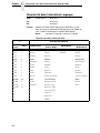
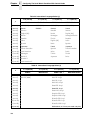
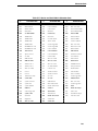
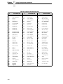
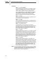
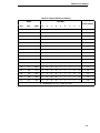
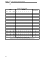
The Control Codes
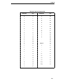
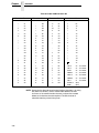
The Control Codes
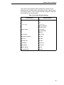
This index lists each printer command by function, ASCII mnemonic, and the
page where the command is explained in detail. “N/A” means not applicable.
The rest of this chapter defines the control code functions for Proprinter III XL
emulation mode. The commands are listed in alphabetical order.
† = Produces non-Proprinter behavior in your printer.
FUNCTION
Paper Motion
Form Feed
Line Feed
Line Feed n/216” (One Line Only)
Tab, Vertical
Tab Set/Clear, Vertical
Tabs, Clear All (Return to default)
ASCII CODE
PAGE
FF
LF
ESC J n
VT
ESC B n1 n2 ... nk NUL
ESC R
40
44
45
58
59
60
Format
† Backspace
Cancel
Carriage Return
Carriage Return Set
Forms Length Set in Inches
Forms Length Set in Lines
Margin, Bottom
Margin, Bottom (Cancel)
Margins, Horizontal
Set Top-of-Form
Tab, Horizontal
Tab Set/Clear, Horizontal
Tabs, Clear All (Return to default)
BS
CAN
CR
ESC 5 n
ESC C NUL n
ESC C n
ESC N n
ESC O
ESC X n m
ESC 4
HT
ESC D n1 n2 nk NUL
ESC R
27
32
33
33
40
41
49
50
50
56
57
57
60
Line Spacing
Line Spacing 1/8 Inch (8 lpi)
Line Spacing 7/72 Inch (10.3 lpi)
Line Spacing n/72 Inch (Executes)
Line Spacing n/72 Inch (Storage)
Line Spacing n/216 Inch
ESC 0
ESC 1
ESC 2
ESC A n
ESC 3 n
46
46
47
48
49
Selection of Character Set
Character Set Select: Set 1 (A)
Character Set Select: Set 2 (B)
ESC 7
ESC 6
34
34
Print Quality
† Bold Printing
Bold Printing, Cancel
† Character Pitch 12 cpi
† Condensed Print
Condensed Print Cancel
† Double Wide Print
† Double Wide Print (One Line Only)
ESC G
ESC H
ESC :
SI
DC2
ESC W n
SO
32
32
34
35
36
36
38
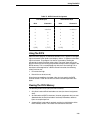
25
Chapter
2
Configuring The Proprinter III XL Emulation With Control Codes
FUNCTION
Double Wide Print (One Line Only)
Cancel
† Emphasized Print
Emphasized Print Cancel
† Overscoring
† Print Mode
† Print Quality
† Proportional Spacing
† Select Attributes
† Superscript/Subscript Printing
Superscript/Subscript Printing, Cancel
† Underline
Bit Image
Bit Image, Single Density
(Normal Speed)
Bit Image, Double Density
(Half Speed)
Bit Image, Double Density,
(Normal Speed)
Bit Image, Quadruple Density,
(Half Speed)
Other Functions
Bell
Deselect Printer
Escape Sequence
Initialize Parameters
Print All Characters
Print Next Character
Super-Set Commands
Unidirectional Printing
26
ASCII CODE
DC4
PAGE
38
ESC E
ESC F
ESC _ n
ESC I n
ESC x n
ESC P n
ESC [ @ n1 NUL NUL NUL n2 n3
ESC S n
ESC T
ESC – n
39
39
51
52
53
53
54
55
56
60
ESC K n1 n2
28
ESC L n1 n2
29
ESC Y n1 n2
30
ESC Z n1 n2
31
BEL
ESC Q 22
ESC
ESC [ K n1 NUL n2 n3 n4 n5
ESC \ n1 n2
ESC ^ n
ESC | } ;
ESC U n
27
36
22
42
51
52
56
60
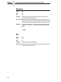
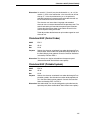
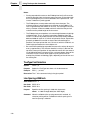
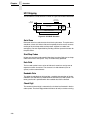
Backspace
Backspace
ASCII
BS
Hex
08
Dec
08
Purpose
Moves the logical print head to the left one character space
toward the first character column.
Discussion BS moves the character position indicator (the logical print head
position) one character space to the left at the current character
pitch setting. This code is ignored if the logical print head is
positioned at the first character column.
When the backspace code is received, printing speed will be
reduced. If the printer is in double width mode, the backspace
code moves the print head left two normal character spaces.
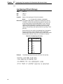
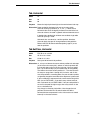
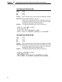
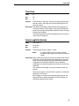
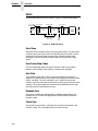
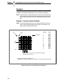
Example
If you were to print five “T” characters, then two BS commands,
then two “=” characters, the output would look like the sample
below:
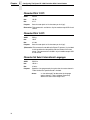
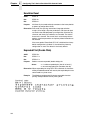
Bell
ASCII
BEL
Hex
07
Dec
07
Purpose
Sounds a buzzer/beeper.
Discussion The BEL function will sound the buzzer/beeper for 0.2 seconds
upon receipt of this command.
27
Chapter
2
Configuring The Proprinter III XL Emulation With Control Codes
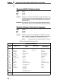
Bit Image Mode, Single Density (Normal Speed)
ASCII
ESC K n1 n2
Hex
1B 4B n1 n2
Dec
27 75 n1 n2
Purpose
Selects single (normal) density bit image graphics.
where:
n1 + 256n2 defines the number of data bytes to
follow.
DATA = ASCII characters for the dot pattern bytes.
Discussion This code prints specified data as bit image graphics at normal
density, 60 dots per inch horizontally and 72 dots per inch
vertically. For more information, see “Graphics Control Codes
Overview” on page 23 and page “Bit Image Graphics” on page
259.
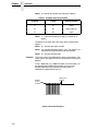
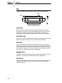
Example
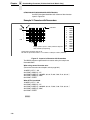
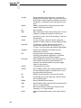
28
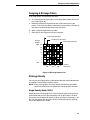
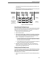
The following example produces a pattern of Single Density Bit
Image graphics. The 9-byte bit pattern is repeated 27 times.
Compare this example to the double density and quadruple
density examples.
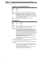
Bit Image Mode, Double Density (Half Speed)
Bit Image Mode, Double Density (Half Speed)
ASCII
ESC L n1 n2
Hex
1B 4C n1 n2
Dec
27 76 n1 n2
Purpose
Selects double density bit image graphics.
where:
n1 + 256n2 defines the number of data bytes to
follow.
DATA = ASCII characters for the dot pattern bytes.
Discussion This code prints specified data as bit image graphics at double
horizontal density, 120 dots per inch horizontally and 72 dots per
inch vertically. This code causes print speed to be reduced by
half from normal density speed. For more information, see
“Graphics Control Codes Overview” on page 23 and “Bit Image
Graphics” on page 259.
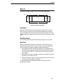
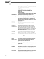
Example
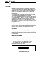
The following example produces Double Density Bit Image
graphics of the pattern used in the Single Density Bit Image
Mode example. Note that the amount of data must be doubled in
order to produce this pattern for double density (the data is used
54 times rather than 27).
29
Chapter
2
Configuring The Proprinter III XL Emulation With Control Codes
Bit Image Mode, Double Density (Normal Speed)
ASCII
ESC Y n1 n2
Hex
1B 59 n1 n2
Dec
27 89 n1 n2
Purpose
Selects double density bit image graphics at single density
speed.
where:
n1 + 256n2 defines the number of data bytes to
follow.
DATA = ASCII characters for the dot pattern bytes.
Discussion This code prints specified data as bit image graphics at double
horizontal density, 120 dots per inch horizontally and 72 dots per
inch vertically. By ignoring adjacent dots, the print speed is not
reduced from the normal density speed. For more information,
see “Graphics Control Codes Overview” on page 23 and “Bit
Image Graphics” on page 259.
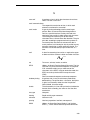
Example
30
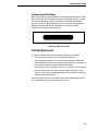
The following example produces a Double Density Normal
Speed Bit Image graphics for the same pattern as in the Normal
(Single) Density example. Note that the amount of data must be
doubled for double density (the data is used 54 times rather than
27).
Bit Image Mode, Quadruple Density (Half Speed)
Bit Image Mode, Quadruple Density (Half Speed)
ASCII
ESC Z n1 n2
Hex
1B 5A n1 n2
Dec
27 90 n1 n2
Purpose
Selects quadruple density bit image graphics.
where:
n1 + 256n2 defines the number of data bytes to
follow.
DATA = ASCII characters for the dot pattern bytes.
Discussion This code prints specified data as bit image graphics at
quadruple density, 240 dots per inch horizontally and 72 dots per
inch vertically. This code causes print speed to be reduced by
half. For more information, see “Graphics Control Codes
Overview” on page 23 and “Bit Image Graphics” on page 259.
Example
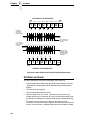
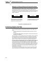
The following example produces quadruple density graphics of
the pattern used in the Single Density Bit Image Mode example.
Note that the amount of data must be quadrupled for quadruple
density (the data is used 108 times rather than 27).
31
Chapter
2
Configuring The Proprinter III XL Emulation With Control Codes
Bold Printing
ASCII
ESC G
Hex
1B 47
Dec
27 71
Purpose
Selects bold character printing.
Discussion When this command is received, all characters are printed in
bold until reset by the Bold Print Reset control code or printer
reset. The bold print attribute is implemented by increasing the
dot density for the bolded text (with a similar result to double
strike printing).
The ESC E (page 39) and ESC G commands are equivalent;
they produce the same print effect.
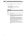
Example
The following sample illustrates bold character printing.
Bold Printing, Cancel
ASCII
ESC H
Hex
1B 48
Dec
27 72
Purpose
Cancels bold printing.
Discussion No other print attributes are changed.
Cancel
ASCII
CAN
Hex
18
Dec
24
Purpose
Clears the print buffer of all symbols since the last paper motion
command was received.
Discussion The CAN command cancels all characters sent to the printer
after the last paper motion command.
This command will cancel the double wide attribute if set by SO.
No other print attributes are affected.
32
Carriage Return
Carriage Return
ASCII
CR
Hex
0D
Dec
13
Purpose
Returns the logical print head to the first character column
(resets the pointer to the first character position). May be
configured to include a line feed.
Discussion The CR code is configured via the ESC 5 code or via the
operator panel menus (described in the User’s Manual). The CR
= CR configuration causes the character position indicator to be
positioned at character column one; subsequent printable data
preceding a paper motion command overstrikes previously
printed data. The CR = CR + LF configuration causes the CR
code to perform a carriage return plus a line feed.
The CR code also cancels expanded (double wide) print when
set by code SO (single line printing attribute).
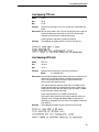
Carriage Return Set
ASCII
ESC 5 n
Hex
1B 35 n
Dec
27 53 n
Purpose
Defines the result from the Carriage Return (CR) code.
where:
n may range from 0 through 255
If n = 0, 2, 4 ... (any even value), then CR = CR (the
default).
If n = 1, 3, 5 ... (any odd value), then CR = CR + LF.
Discussion This command overrides the configuration menu setting.
•
CR = CR (default) configuration causes the character position indicator to
be positioned at character column one. Subsequent printable data
preceding a paper motion command overstrikes previous printable data.
•
CR = CR + LF configuration causes the CR code to perform a carriage
return plus a line feed.
33
Chapter
2
Configuring The Proprinter III XL Emulation With Control Codes
Character Pitch 12 cpi
ASCII
ESC :
Hex
1B 3A
Dec
27 58
Purpose
Sets character pitch to 12 cpi.
Discussion An ESC: code overrides any operator panel setting.
Character Set Select: Set 1 (A)
ASCII
ESC 7
Hex
1B 37
Dec
27 55
Purpose
Selects hex codes 80 through 9F in the character sets as control
codes. Cancels the command ESC 6.
Discussion This control code overrides the operator panel setting (described
in the User’s Manual).
Character Set Select: Set 2 (B)
ASCII
ESC 6
Hex
1B 36
Dec
27 54
Purpose
Selects hex codes 80 through 9F in the character sets as
printable symbols. Cancels the command ESC 7.
Discussion This control code overrides the operator panel setting.
34
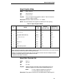
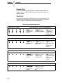
Condensed Print
Condensed Print
ASCII
SI
ESC SI
Hex
0F
1B 0F
Dec
15
27 15
Purpose
Sets condensed print.
Discussion You may enable or disable the condensed print feature using the
operator panel (the default setting for the Condensed Print
option is enabled). Once condensed print is enabled, this control
code sets condensed print until it is canceled by control code
DC2, a printer reset, or a new print mode (ESC I) control code.
The manner in which the print is condensed varies depending on
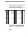
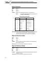
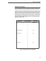
the initial print size. Several examples are listed in Table 4:
Table 4. Condensed Print
Initial Print Size
Condenses To
5 cpi
8.55 cpi
6 cpi
10 cpi
8.58 cpi
no change
10 cpi
17.16 cpi
12 cpi (except NLQ)
20 cpi
† 12 cpi NLQ
17.16 cpi
17.16 cpi
no change
20 cpi
no change
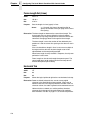
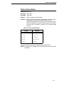
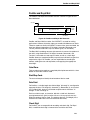
Example
The following sample shows condensed character printing and
reset.
35
Chapter
2
Configuring The Proprinter III XL Emulation With Control Codes
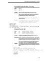
Condensed Print Cancel
ASCII
DC2
ESC DC2
Hex
12
1B 12
Dec
18
27 18
Purpose
Cancels condensed character printing and sets pitch to 10 cpi.
Discussion The Condensed Print Cancel command sets the character pitch
to 10 cpi, or 5 cpi if printing is set for double wide.
Example
See the SI control code (page 35) for an example of Condensed
Print Cancel.
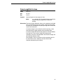
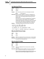
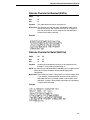
Deselect Printer
ASCII
ESC Q 22
Hex
1B 51 16
Dec
27 81 22
Purpose
Stops the printer from processing data received from the host
computer.
Discussion This code is for diagnostic use; it instructs the printer to stop
processing data received from the host system. In order to
resume processing data, the printer must be reset from the host
system.
Example
Using the BASIC language, you may deselect the Proprinter III
XL with the following:
LPRINT CHR$(27);CHR$(81);CHR$(22);
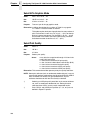
Double Wide Print
ASCII
ESC W n
Hex
1B 57 n
Dec
27 87 n
Purpose
Selects or cancels double wide (expanded) print.
where:
n may range from 0 through 255
If n = 1, 3, 5 ... (any odd value), double wide print is
selected.
If n = 0, 2, 4 ... (any even value), double wide print
is cancelled.
Discussion An ESC W code sets or cancels double wide print, as follows:
When expanded print using ESC W is received, all characters
print double wide until cancelled by an even parameter hex
code.
Double wide print can also be set via the command SO and ESC
SO, double wide print for one line only. An ESC W code
overrides these settings.
36
Double Wide Print
The manner in which the print is expanded varies depending on
the initial print size. Several examples are listed in Table 5:
Table 5. Double-Wide Print
Initial Print Size
Expands To
5 cpi
no change
6 cpi
no change
8.58 cpi
no change
10 cpi
5 cpi
12 cpi
6 cpi
17.16 cpi
8.55 cpi
20 cpi
10 cpi
Example
The following sample illustrates expanded character printing and
expanded character printing reset.
37
Chapter
2
Configuring The Proprinter III XL Emulation With Control Codes
Double Wide Print (One Line Only)
ASCII
SO
ESC SO
Hex
0E
1B 0E
Dec
14
27 14
Purpose
Selects double wide print for one line only.
Discussion This expanded print command is a line-by-line print attribute;
when the SO or ESC SO command is received, the current line
will be printed double wide and automatically reset. This
command can be reset by a paper motion command (FF, LF,
VT, CR), by the DC4 (double wide cancel) code, CAN or ESC W
(double wide print).
See the previous control code (ESC W) for examples of print
expansion for various initial print sizes.
Example
The following sample illustrates Expanded Print for one line only.
Double Wide Print (One Line Only) Cancel
ASCII
DC4
ESC DC4
Hex
14
1B 14
Dec
20
27 20
Purpose
Cancels double wide print, if it was set by command SO.
Discussion The DC4 code cancels Double Wide Print command SO. If
Double Wide Print is not enabled, the DC4 code is ignored. A
DC4 code can occur at any place in the datastream and is acted
upon immediately.
38
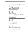
Emphasized Print
Emphasized Print
ASCII
ESC E
Hex
1B 45
Dec
27 69
Purpose
Selects emphasized character print format.
Discussion When the emphasized print command is received, all characters
will be printed in emphasized (bold) print until reset by the
Emphasized Print Reset command or printer reset. Emphasized
print reduces the current print speed.
NOTE: The ESC G (page 32) and ESC E commands are equivalent; they
produce the same print effect.
Example
The following sample illustrates emphasized character printing.
Emphasized Print Cancel
ASCII
ESC F
Hex
1B 46
Dec
27 70
Purpose
Cancels emphasized character printing.
Discussion The emphasized print reset command only resets the
emphasized print character attribute. See Example above for
using ESC E combined with ESC F.
39
Chapter
2
Configuring The Proprinter III XL Emulation With Control Codes
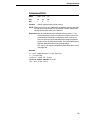
Form Feed
ASCII
FF
Hex
0C
Dec
12
Purpose
Prints the data in the buffer, advances the paper to the next topof-form, and moves the logical printhead to the first character
column.
Discussion Forms length is set by using the operator panel or forms length
control codes. This code cancels double wide (expanded)
characters if set by the SO command.
The Form Feed command will react differently when the VFU is
active. Refer to Chapter 9 for further information.
Forms Length Set in Inches
ASCII
ESC C NUL n
Hex
1B 43 00 n
Dec
27 67 0 n
Purpose
Sets the length of forms (paper) in inches.
where:
n = whole numbers from 1 through 24 to specify the
number of inches on a page. (All larger values are
ignored.)
Discussion Upon receipt of this code, the current line becomes the first line
of the form, and the forms length set becomes the current forms
length. Vertical tab positions set below the bottom of the form
are ignored; in addition, once a new forms length is set the
bottom margin is set to zero.
Line spacing changes do not affect the result of this command. If
the forms length is set smaller than the line spacing, a form feed
advances the paper position to the next top-of-form position.
Forms length in inches can also be set at the operator panel via
the Print Format menu. However, this host control code
overrides the operator panel setting.
40
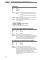
Forms Length Set in Lines
Forms Length Set in Lines
ASCII
ESC C n
Hex
1B 43 n
Dec
27 67 n
Purpose
Sets the length of a form (paper) in lines.
where:
n = 1 through 192 (1 through C0 hex) to specify the
number of lines per page at the current line
spacing.
Discussion The forms length is defined in inches as the quotient of n divided
by the current lines per inch (lpi) setting. Once the forms length
has been set, subsequent line spacing changes do not affect the
result of this command.
If the forms length is set smaller than the line spacing, a form
feed advances the paper position to the next top-of-form.
If the forms length derived from the quotient of n lines divided by
lines per inch is not an exact multiple of the printer dot
resolution, the value is adjusted down until the forms length and
dot resolution distance match.
Forms length in lines can also be set at the operator panel via
the Print Format menu. However, this host control code
overrides the operator panel setting.
41
Chapter
2
Configuring The Proprinter III XL Emulation With Control Codes
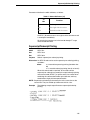
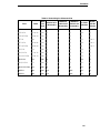
Initialize Parameters
ASCII
ESC [ K n1 NUL n2 n3 n4 n5
Hex
1B 5B 4B n1 00 n2 n3 n4 n5
Dec
27 91 75 n1 0 n2 n3 n4 n5
Purpose
Sets the printer initial condition.
Discussion This command causes the printer to reset and defines the
configuration that will be loaded to the printer during the reset.
Several variables must be specified to define the load
configuration, as described below.
NOTE: An ESC[K code can occur at any place in the datastream and is acted
upon immediately. All numerical parameters are in the hex 00 through
FF range unless stated otherwise. Only specified parameters are
supported. Other values may be ignored or cause unpredictable
results, and should be avoided.
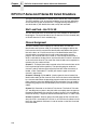
n1
The value of n1 defines which of the following n bytes will be
included in the command line, as shown in Table 6.
Table 6. Defining Bytes in the Command Line
n1
Function
Hex Value
IMPORTANT
1
One byte follows (n2)
3
Three bytes follow (n2, n3, and n4)
4
Four bytes follow (n2, n3, n4, and n5)
Specifying any value for n1 other than 1, 3, or 4 may cause
unpredictable results, and should be avoided.
n2
The 2-digit hexadecimal value for n2 defines the load
configuration for the printer. The Proprinter III XL supports six
hexadecimal values for this parameter: 00, 01, 04, 05, 254, and
255. The following table describes the different load
configurations that will result with each value:
Table 7. Load-up Configuration
n2
Hex Value
42
Function
00, 01, 254
The printer will load the power-up configuration that is
stored in memory. Configuration changes that are defined
by command bytes n4 and n5, if present, will override
conflicting values stored in memory.
04, 05, 255
The printer will load the factory default configuration.
Configuration parameters defined by command bytes n4
and n5, if present, will override conflicting factory default
values.
Initialize Parameters
n3
Parameter n3 is provided for compatibility with the Proprinter III
XL printer control language standard. You may define any value
for this parameter. (For Proprinters, this bit must define the
attached printer as either Proprinter III, hex value 03, or
Proprinter III XL, hex value 16.)
n4 and n5
Parameter bytes n4 and n5 allow you to define several
configuration parameters that will override conflicting factory
default and NVRAM-based configuration values when the printer
is reinitialized. Depending on the value that is defined for n2
(refer to Table 7), these values may also be saved to memory.
NOTE: In addition to the formatting from bytes n4 and n5, this command sets
the current line as top-of-form. It also clears vertical tabs and sets the
horizontal tabs at every eight columns, starting at column 9.
Table 8. Configuration Parameters (n4)
n4 Bit
Function
OFF (0)
ON (1)
7
Process this byte.
Process
Ignore
6
Reserved
Reserved
Reserved
5
N/A
--------
----------
4
Line Feed =
LF
LF + CR
(add CR with each LF)
3
Carriage Return =
CR
CR + LF
(add LF with each CR)
2
Set forms length
11”
12”
1
Slashed zero
Disable
Enable
0
Character set
1 (A)
2 (B)
Table 9. Configuration Parameters (n5)
n5 Bit
Function
OFF (0)
ON (1)
7
Process this byte.
Process
Ignore
6
Code page
437
850
5
Unidirectional printing
bidirectional
unidirectional
4
12 cpi compressed to 20
20
12
3
n/a
---
---
2
Form feed at TOF
Enable
Ignore
1
Print width
13.6 inch
8 inch
0
Sheet feeder
N/A
N/A
43
Chapter
2
Configuring The Proprinter III XL Emulation With Control Codes
Line Feed
ASCII
LF
Hex
0A
Dec
10
Purpose
Prints the data in the buffer (if any) and advances the paper one
line at the current line space setting.
Discussion If configured for LF equals new line (LF = CR + LF), the logical
print head is positioned at character column 1 of the new line.
Otherwise, the logical print head does not move when
configured for LF function only (LF = LF only). The LF function
cancels double wide (expanded) characters if set by the SO
command.
Line feed can occur at any place in the datastream and is acted
upon immediately.
44
Line Feed n/216 Inch (One Line Only)
Line Feed n/216 Inch (One Line Only)
ASCII
ESC J n
Hex
1B 4A n
Dec
27 74 n
Purpose
Advances the vertical character position n/216 inch for one line
only.
where:
n = 1 through 255
Discussion The n/216-inch line feed control code is effective for one line
only. All single-line-only print attributes are canceled.
If the emulation is configured for LF equals newline
(LF=CR+LF), the paper advances one line at the current line
space setting and the logical print head is positioned at
character column 1.
The paper position moves only in multiples of the current dot row
spacing. If the distance to move is other than a multiple of the
current dot row spacing, the remainder is added to the next
paper motion command.
Small values of n may result in overlapping lines. Overlapping
lines may also occur if print attributes such as Elongated
(Double High), Superscript, or Subscript characters are used on
the same line. Printing at different horizontal and vertical
densities will not overlap.
Example
The following example illustrates n/216-inch line spacing.
45
Chapter
2
Configuring The Proprinter III XL Emulation With Control Codes
Line Spacing 1/8 Inch (8 lpi)
ASCII
ESC 0
Hex
1B 30
Dec
27 48
Purpose
Specifies continuous line spacing at 1/8-inch increments (8 lpi).
Discussion When the 1/8-inch line spacing control code is received, all lines
will be printed at 8 lpi until a new line spacing is selected or the
printer is reset.
Example
The following example illustrates 1/8-inch line spacing.
Line Spacing 7/72 Inch (10.3 lpi)
ASCII
ESC 1
Hex
1B 31
Dec
27 49
Purpose
Specifies the line spacing at 7/72-inch (10.3 lpi) increments.
Discussion When the 7/72-inch line spacing control code is received, all
lines will be printed at the 7/72-inch line spacing until a new line
spacing is selected or the printer is reset. The control code line
spacing selection will override the operator panel line spacing
setting, and the message display will reflect the line spacing as
10.3 lines per inch.
Caution should be used when combining this control code with
other print attributes such as Elongated (Double High),
Superscript, or Subscript; overlapping lines may occur.
Example
46
The following example illustrates 7/72-inch line spacing.
Line Spacing n/72 Inch (Executes)
Line Spacing n/72 Inch (Executes)
ASCII
ESC 2
Hex
1B 32
Dec
27 50
Purpose
ESC 2 sets line spacing to 6 lpi or as set by ESC A.
Discussion ESC 2 asserts n/72-inch line spacing as set by ESC A (page
page 47). If no distance has been set by ESC A, the distance is
1/6 inch.
The control code line spacing selection will override the operator
panel line spacing setting.
Example
The following example illustrates 1/6-inch line spacing and
assumes that a distance has not been set by ESC A.
47
Chapter
2
Configuring The Proprinter III XL Emulation With Control Codes
Line Spacing n/72 Inch (Storage)
ASCII
ESC A n
Hex
1B 41 n
Dec
27 65 n
Purpose
Stores a line spacing of n/72-inch increments.
where:
n = 1 through 255 (all others are ignored)
Discussion This control code stores a value for line spacing of n/72 inch.
The ESC 2 control code (described on page 47) executes the
line spacing stored by the preceding ESC A, until a new line
spacing is selected or power to the printer is reset. A control
code line spacing overrides an operator panel line spacing
setting. (The operator panel display shows line spacing in lines
per inch.)
Small values of n may result in overlapping lines. Overlapping
lines may also occur if print attributes such as Elongated
(Double High), Superscript, or Subscript characters are used on
the same line. Common values of n are shown in Table 10.
Table 10. Line Spacing (n/72 inch)
n
Example
48
Line Spacing
24
3 lpi
18
4 lpi
12
6 lpi
9
8 lpi
8
9 lpi
6
12 lpi
The following example illustrates 20/72-inch line spacing.
Line Spacing n/216 Inch
Line Spacing n/216 Inch
ASCII
ESC 3 n
Hex
1B 33 n
Dec
27 51 n
Purpose
Specifies the line spacing at n/216-inch increments.
where:
n = 1 through 255
Discussion When the n/216-inch line spacing control code is received, all
line feeds following will be at n/216-inch line spacing until a new
line spacing is selected or the printer is reset. The control code
line spacing selection will override the control panel line spacing
setting.
The vertical character position moves only in multiples of the
current dot row spacing. If the distance to move is other than a
multiple of the current dot row spacing, the remainder is added
to the next paper motion command.
Caution should be used when combining this control code with
other print attributes such as Elongated (Double High),
Superscript, or Subscript; overlapping lines may occur.
Example
The following example illustrates n/216-inch line spacing.
Margin, Bottom
ASCII
ESC N n
Hex
1B 4E n
Dec
27 78 n
Purpose
Sets the bottom margin.
Discussion n defines the number of lines above the bottom of the form to set
as the bottom margin. n has a range from 1 through 255. The
actual margin in inches is the quotient of n divided by the current
lines per inch (lpi).
If a line feed command causes the active position to advance
below the bottom margin, the paper advances to the top of the
next form. If the bottom margin is set equal to or greater than the
form length, printing is only allowed on the top line of each page.
If the forms length is changed by the ESC C code (Forms Length
sequence), the bottom margin is set to zero.
The bottom margin setting can also be selected from the
operator panel; however, the host control code will override the
operator panel setting. Any vertical tabs set within the bottom
margin zone will be ignored.
49
Chapter
2
Configuring The Proprinter III XL Emulation With Control Codes
Margin, Bottom (Cancel)
ASCII
ESC O
Hex
1B 4F
Dec
27 79
Purpose
Resets the bottom margin to zero.
Margins, Horizontal
ASCII
ESC X n m
Hex
1B 58 n m
Dec
27 88 n m
Purpose
Sets left and right margins in character positions.
where:
n = left margin position
m = right margin position
Discussion The values of n and m must be in the range from 0 through 255.
The margins are measured in character positions at the current
characters per inch (cpi).
The value set for n is the left margin, where n is the number of
character positions from the left edge of the paper. The left
margin in inches is the quotient of the value for n divided by the
current cpi. Once the left margin is set, later changes in the cpi
do not affect the margin setting.
The value set for m is the right margin, where m is the number of
character positions from the left edge of the paper. The right
margin in inches is the quotient of the value for m divided by the
current cpi. Once the right margin is set, later changes in the cpi
do not affect the margin setting.
50
Overscoring
Overscoring
ASCII
ESC _ n
Hex
1B 5F n
Dec
27 95 n
Purpose
Enables or disables automatic overscoring of all characters.
where:
n may range from 0 through 255
n = 00, 02, 04 (any even value) disables automatic
overscoring
n = 01, 03, 05 (any odd value) enables automatic
overscoring
Discussion When automatic overscore is enabled, all characters, including
spaces, are overscored. Full-height graphics characters are not
overscored. (Full-height characters are in the upper ASCII
character set for code pages 437 and 850, in positions 176-233,
or 244.)
Example
The following sample illustrates automatic overscoring and
overscoring reset.
Print All Characters
ASCII
ESC \ n1 n2
Hex
1B 5C n1 n2
Dec
27 92 n1 n2
Purpose
Prints the characters assigned to code points as characters,
rather than interpreting the code values as commands.
where:
n1 + 256n2 defines the number of data bytes to
follow.
Discussion The number of data bytes specified by n1 + 256n2 will print as
text. Valid numerical parameters are in the range hex 00 through
hex FF. Data values that do not correspond to standard ASCII
codes will print as spaces.
51
Chapter
2
Configuring The Proprinter III XL Emulation With Control Codes
Print Next Character
ASCII
ESC ^ n
Hex
1B 5E n
Dec
27 94 n
Purpose
Prints the graphic character assigned to n, rather than
interpreting the code value as a command.
Discussion This command may appear anywhere in the data stream, and
will be acted upon immediately. Valid numerical parameters are
in the range hex 00 through hex FF.
Print Mode
ASCII
ESC I n
Hex
1B 49 n
Dec
27 73 n
Purpose
Selects a print mode.
Discussion This control code selects a print mode from among the choices
in Table 11.
Table 11. Print Mode
n (Hex)
Function
0
DP
1
Draft 12 CPI
2
NLQ Sans Serif
3
NLQ Serif
4
DP
5
Draft 12 CPI
6
NLQ Sans Serif
7
NLQ Serif
8
NLQ Serif-Italic-Proportional
9
NLQ Serif-Italic
There are several duplicate Hex values that select the same
print quality. These are provided for compatibility with the
Proprinter III XL standard.
IMPORTANT
52
If you specify any value other than those shown in Table 11,
unpredictable results may occur.
Print Quality
Print Quality
ASCII
ESC x n
Hex
1B 78 n
Dec
27 120 n
Purpose
This code selects a print quality.
where:
Comment
n = hex 0 or hex 30 selects DP print quality
n = hex 1 or hex 31 selects NLQ Serif print quality
n = hex 2 or hex 32 selects Draft print quality
n = hex 3 or hex 33 selects OCR A print quality
n = hex 4 or hex 34 selects OCR B print quality
Print qualities selected with this command override operator
panel selections. Selecting an OCR print quality overrides any
character attributes already set, such as condensed, doublewide, etc., and forces 10 cpi. Character attributes set when OCR
is selected will be ignored.
NOTE: Some print attributes (such as condensed, double-wide, etc.) may not
return to their previous setting when changing from OCR-A or OCR-B
back to another Print Quality. For guaranteed results, all print
attributes should be set after the Print Quality is selected.
Proportional Spacing
ASCII
ESC P n
Hex
1B 50 n
Dec
27 80 n
Purpose
Enables/disables proportional spacing of characters.
where:
Comment
n may range from 0 through 255
n = 1, 3, 5...(any odd value) enables proportional
spacing
n = 0, 2, 4...(any even value) disables proportional
spacing
This command is ignored when a non-proportional font is used.
53
Chapter
2
Configuring The Proprinter III XL Emulation With Control Codes
Select Attributes
ASCII
ESC [ @ n1 NUL NUL NUL n2 n3
Hex
1B 5B 40 n1 00 00 00 n2 n3
Dec
27 91 64 n1 0 0 0 n2 n3
Purpose
Selects double high and double wide attributes, and single or
double high line spacing.
Discussion Parameter n1 selects the attributes from n2 and n3, as follows:
Table 12. Select Attributes (n1)
n1
Hex Value
Function
03
Set character height and line feed settings according to
the value of n2 (If n1 = 03, there is no n3.)
04
Set character height, line feed, and character settings
according to the values of n2 and n3.
Parameter n2 defines the height attributes, as follows:
Table 13. Select Attributes (n2)
n2
Hex Value
54
Function
00
No change
01
Set single line height characters
02
Set double height characters
10
Set single line spacing
11
Set single height characters and single line spacing
12
Set double height characters and single line spacing
20
Set double line spacing
21
Set single height characters and double line spacing
22
Set double height characters and double line spacing
Superscript/Subscript Printing
Parameter n3 defines the width attributes, as follows:
Table 14. Select Attributes (n3)
n3
Hex
Function
00
No change
01
Set single wide characters
02
Set double wide characters
An ESC [ @ code can occur at any place in the datastream and
is acted upon immediately.
All numerical parameters are in the hex 00 through FF range
unless stated otherwise.
Superscript/Subscript Printing
ASCII
ESC S n
Hex
1B 53 n
Dec
27 83 n
Purpose
Selects superscript or subscript printing.
where:
n may range from 0 through 255
n = 01, 03, 05 (any odd value), selects subscript
printing.
n = 00, 02, 04 (any even value), selects superscript
printing.
Discussion When the super/subscript command is received, all characters
will be superscript or subscript until reset by the super/subscript
reset command or printer reset. Super/subscript print modes are
not available for the double high attribute.
NOTE: Superscript and subscript characters print at the same size as the
current font, shifted up or down relative to the print line.
Example
The following sample illustrates superscript/subscript printing.
55
Chapter
2
Configuring The Proprinter III XL Emulation With Control Codes
Superscript/Subscript Printing, Cancel
ASCII
ESC T
Hex
1B 54
Dec
27 84
Purpose
Cancels superscript and subscript printing (as set by ESC S).
This code can occur at any place in the datastream and is acted
upon immediately.
Super-Set Commands
ASCII
ESC | } ;
HEX
1B 7C 7D 3B
Dec
27 124 125 59
Purpose
Control code sequence used to introduce the super-set
commands.
Discussion The “|” in the command string is the pipe symbol.
Comment
Super-set commands affect the ASCII emulation as a whole
regardless of the printer protocol currently active. The
commands are sent through the host in the input data stream,
and enact the following features:
• Select a printer protocol
• Bar codes
• Set variable character spacing
• Set variable line spacing
Refer to Chapter 7, “Super-Set Programming,” for further information
regarding the super-set commands.
Set Top-of-Form
56
ASCII
ESC 4
Hex
1B 34
Dec
27 52
Purpose
Sets the current paper position as the top-of-form.
Tab, Horizontal
Tab, Horizontal
ASCII
HT
Hex
09
Dec
09
Purpose
Moves the logical printhead right to the next horizontal tab stop.
Discussion Power-on default horizontal tabs are set at every eighth
character starting at position 9 (9, 17, 25 ...). If there are no
horizontal tabs set or the logical printhead is located at the last
character column, the code is ignored and no movement occurs.
If double-wide, double-high attributes are enabled, single-wide
character spacing is used.
Horizontal tabs are stored as a relative position; therefore,
character pitch changes will change horizontal tab positions.
Refer to the ESC D control code description (page 57) to set
new tab positions.
Tab Set/Clear, Horizontal
ASCII
ESC D n1 n2...nk NUL
Hex
1B 44 n1 n2...nk 00
Dec
27 68 n1 n2...nk 0
Purpose
Sets up to 28 horizontal tab positions.
Discussion n1, n2, up to nk denote character column positions for tab stops
(at the current character pitch), where n1 and n2 represent the
first two tab stops and nk is the final tab stop. You may specify
from 1 up to 28 tab stops (all parameters after 28 are ignored).
The leftmost character column position is 1. The value for each
tab stop can range from 1 through 255, inclusive, and all tabs
must be specified in ascending order. Any out-of-order symbols
are ignored, though the remainder of the sequence is processed.
If you are defining a sequence of tabs, terminate the string with a
NUL (not an ESC D NUL). If you want every column to be set
with a horizontal tab, use ESC D NUL. If only one tab position is
set and it is beyond the right margin, then every column is also
set as a horizontal tab.
Any change in character pitch within a line changes the tab
positions for the entire line. All control codes that define
horizontal distance expressed in units of characters are stored
internally in character columns.
57
Chapter
2
Configuring The Proprinter III XL Emulation With Control Codes
Example
The following example illustrates horizontal tab setting and
accessing.
Tab, Vertical
ASCII
VT
Hex
0B
Dec
11
Purpose
Prints the data in the buffer and advances the paper to the next
vertical tab position.
Discussion In the Proprinter III XL emulation, vertical tab positions are set by
control code ESC B and executed by control code VT. In this
mode, if vertical tabs are loaded, the paper position moves to the
next vertical tab position.
If a vertical tab format is not defined, the paper position is
advanced to the next line at the current line spacing. If a vertical
tab format is defined but no vertical tab positions are set
between the current print position and the end of the form, the
paper position is advanced to the top of the next form. The VT
code resets all single line print attributes. More information on
vertical tabs is provided in Chapter 9.
If configured for LF = CR + LF (LF equals new line), the
character position indicator is positioned at character column 1
of the new line. Otherwise, the character position indicator does
not move.
58
Tab Set/Clear, Vertical
Tab Set/Clear, Vertical
ASCII
ESC B n1 n2 ... nk NUL
Hex
1B 42 n1 n2 nk 00
Dec
27 66 n1 n2 nk 0
Purpose
Sets or clears vertical tab positions.
Discussion The physical position on the paper is defined by n and the
current line spacing.
where:
n = vertical tab setting (in lines), and k = number of
tabs possible.
The value of n can be defined in the range of 1 through 255,
inclusive, while k is defined in the range of 1 through 64. Any
value for k over 64 is ignored. Subsequent line spacing changes
affect the tab position. If the value of n exceeds the forms length,
that tab position is ignored.
Vertical tab positions are set by the command ESC B and
executed by the command VT. The tab positions must be in
ascending order, or the emulation ignores the out-of-order
symbols. If the ESC B command is followed immediately by 00H,
the vertical tab positions are cleared.
Example
The following sample illustrates Vertical Tab Setting. To run the
sample, set your printer at top-of-form.
59
Chapter
2
Configuring The Proprinter III XL Emulation With Control Codes
Tabs, Clear All (Return to default)
ASCII
ESC R
Hex
1B 52
Dec
27 82
Purpose
Clears all horizontal and vertical tab stops.
Discussion When ESC R is invoked, horizontal tab stops reinitialize to every
eight columns, starting at column 9 (9, 17, 25,...). In addition, the
vertical tabs are cleared.
Underline
ASCII
ESC – n
Hex
1B 2D n
Dec
27 45 n
Purpose
Enables or disables automatic underlining of all characters.
Discussion When automatic underline is enabled, all characters, including
spaces, are underlined until disabled.
where:
Example
n may range from 0 through 255
n = 01, 03, 05 ... (any odd value) selects
underlining.
n = 00, 02, 04 ... (any even value) cancels
underlining.
The following sample illustrates automatic underlining and
underlining reset.
Unidirectional Printing
ASCII
ESC U n
Hex
1B 55 n
Dec
27 85 n
Purpose
Sets or cancels unidirectional printing.
Discussion This code sets or cancels unidirectional printing, as follows:
where:
60
n may range from 0 through 255
n = 01, 03, 05 ... (any odd value) selects
unidirectional text printing.
n = 00, 02, 04 ... (any even value) cancels
unidirectional text printing.
3
Epson FX-1050 Emulation
Overview
This chapter describes the Epson FX emulation host control codes.
“Emulation” refers to the ability of a printer to execute the commands of a
particular printer control language. A printer control language is the coding
system used to convey, manipulate, and print data. It contains character
codes and command sequences that configure the emulation. In this manual,
the terms emulation, printer protocol, and printer control language are
synonymous.
In Epson FX emulation mode, your printer can print files coded for the Epson
FX printer control language. To select the Epson FX emulation as the active
printer emulation, select LinePrinter Plus from the EMULATION menu and
Epson FX from the Printer Protocol menu, as described in the User's Manual.
The Epson FX emulation provides many configurable parameters. The default
parameter values for this emulation are shown in Table 15. You can modify
these parameter values in two ways:
•
The Epson FX host control codes. An extensive set of Epson FX
control code commands can be sent to the printer from an attached host
computer via the host data stream. Most of this chapter is devoted to
describing the Epson FX control code commands.
•
The printer configuration menus. You can modify a subset of the
Epson FX emulation parameters using the control panel keys and LCD
display, as described in the User's Manual.
A parameter value set by a host control code generally overrides a value set
from the printer's control panel.
Configuration values selected from the menus or via host control codes can
be saved to the printer's NVRAM memory so that they will not be lost when
you power off the printer or reset it to the factory defaults. The menu selection
for saving a configuration to memory is described in the User's Manual. Refer
to Appendix B, “PTX_SETUP Option” to save the configuration using host
control codes.
61
Chapter
3
Overview
Default Values And States
Your printer memory stores a set of typical operating states and conditions for
the Epson emulation. When you power on the printer and select this
emulation, the factory settings in Table 15 are automatically invoked.
Table 15. Epson Emulation Default Settings
Characteristic
62
Default Setting
Character Set
Epson Set
Epson Print Language
ASCII (USA)
Define CR Code
CR = CR
Auto Line Feed
Enable
Define LF Code
LF = LF
Printer Select
Disable
20 CPI Condensed
Enable
Default Values And States
Table 16 lists several additional default settings for parameters that are
provided by the Print Format menus (described in the User’s Manual). Many
of the settings shown in Table 16 can be overridden by Epson FX-1050 host
control codes for the same parameter.
Table 16. Print Format Default Settings
Characteristic
Default Settings
CPI
10.0
LPI
6.0
Forms Width
13.6 inches
345.4 millimeters
136 characters
Forms Length
11.0 inches
279 millimeters
66 lines
Print Quality
DP Quality
Proportional Spacing
Disable
Italic Print
Disable
Slashed Zero
Disable
Left Margin
0 columns
Right Margin
0 columns
Bottom Margin
0 lines
Perforation Skip
Disable
63
Chapter
3
Overview
Epson Emulation Exceptions And Differences
Because of mechanical differences between your printer(s) (line matrix
printers) and Epson printers (moving printhead serial matrix printers), some
Epson features are approximated or not supported.
•
Epson codes that produce different behavior in your printer are indicated
by a “dagger” (†) in the Control Code Index and code section.
•
The Epson emulation supports the following fonts: DP, NLQ Serif and
Sans Serif, Draft with 10 cpi, 12 cpi and 15 cpi in either condensed or
normal widths, and OCR A and OCR B in 10 cpi. Condensed printing at
10 cpi in DP quality maps to 17.1 cpi. Character pitches other than 10 DP
cpi map to 20 cpi in DP and 17.1 cpi in NLQ.
•
Epson bit-image graphics are supported, including all plotter and CRT
densities.
•
Many character sets are available, including IBM-PC Graphics (IBM Code
Page 0437) and Epson. You can configure the zero character to contain a
slash or no slash.
•
The Double Wide print control codes (ESC W, SO) double character
width, but not inter-character spacing, unlike the Epson FX-1050. The
formulas for total character spacing are as follows:
Epson FX-1050
Epson Emulation
64
2 (char + 1 dot + space)
2 (char + 1 dot) + space
•
The Condensed Print (SI) control code condenses character width but not
inter-character spacing, unlike the Epson FX-1050 which condenses both
character width and spacing.
•
If one or more Backspace control codes follow directly after a Bit Image
Graphics command (ESC K, ESC L, ESC Y, or ESC Z), the printer will
backspace into the graphic pattern, the number of dots depending on the
current cpi setting. For an Epson FX-1050 printer, one Backspace will
send the logical printhead directly to the beginning of the graphics
pattern.
•
When backspacing over proportionally spaced characters, Epson printers
move back the width of each proportional character; this emulation moves
back based on the current cpi setting, as if proportional spacing is
disabled.
Epson Character Sets
Epson Character Sets
Epson printers use five character sets. The IBM Graphics code page 437,
IBM PC Multilingual code page 0850, OCR A, and OCR B character sets may
be selected from the configuration menus. In addition, there is a unique
Epson character set. The Epson character set (shown in Table 17) is basically
the ASCII character set with the upper, non-ASCII set defined as italics, and
the usually unprintable codes designated as international characters.
Table 17. Epson Character Set
Hex
0
1
2
3
4
5
6
7
8
9
A
B
C
D
E
F
0
à
§
SP
0
@
P
‘
p
à
§
SP
0
@
P
‘
p
1
è
ß
!
1
A
Q
a
q
è
ß
!
1
A
Q
a
q
2
ù
DC2
“
2
B
R
b
r
ù
Æ
“
2
B
R
b
r
3
ò
DC3
#
3
C
S
c
s
ò
æ
#
3
C
S
c
s
4
ì
DC4
$
4
D
T
d
t
ì
ø
$
4
D
T
d
t
5
°
ø
%
5
E
U
e
u
°
ø
%
5
E
U
e
u
6
£
¨
&
6
F
V
f
v
£
¨
&
6
F
V
f
v
7
BEL
Ä
‘
7
G
W
g
w
i
Ä
’
7
G
W
g
w
8
BS
CAN
(
8
H
X
h
x
¿
Ö
(
8
H
X
h
x
9
HT
Ü
)
9
I
Y
i
y
Ñ
Ü
)
9
I
Y
i
y
A
LF
ä
*
:
J
Z
j
z
ñ
ä
*
:
J
Z
j
z
B
VT
ESC
+
;
K
[
k
{
¤
ö
+
;
K
[
k
{
C
FF
ü
’
<
L
\
l
|
Pt
ü
,
<
L
\
l
|
D
CR
É
–
=
M
]
m
}
Å
É
–
=
M
]
m
}
E
SO
é
.
>
N
^
n
~
å
é
.
>
N
^
n
~
F
SI
¥
/
?
O
_
o
DEL
Ç
¥
/
?
O
_
o
ø
The international characters in hex 00-1F and hex 80-9F appear when you
invoke control code “ESC I 1”. You may use the Epson configuration menus
described in the User’s Manual (or the “ESC R” control code) to select an
international character set. Table 18 provides detailed notes on print mode
support for each character set.
Normally, these characters are either blank or control codes. The
implementation is that the control codes hide the non-italic international
characters, even in hex 00 through 1F, and DEL. DEL conceals the non-italic
slashed zero.
65
Chapter
3
Configuring The Epson FX-1050 Emulation With Control Codes
Configuring The Epson FX-1050 Emulation With Control
Codes
The remainder of this chapter describes the Epson printer control language
codes that may be sent from a host computer attached to the printer, in order
to invoke and configure numerous Epson emulation functions.
Format For Control Code Descriptions
The following information is listed for each control code (where applicable):
Name
The title or function of the command.
ASCII
The ASCII mnemonic for the command. Command sequences
are in 7-bit (ASCII) form.
Hex
The code or command sequence in hexadecimal numbers.
Dec
The code or command sequence in decimal numbers.
Purpose
The function(s) of the control code.
Discussion A discussion of the uses of the code or command sequence,
including a description of exceptions or limitations to normal use.
IMPORTANT
Example
A sample output is provided when it is possible to illustrate the
effect of a control code or if a specific syntax is required.
†
This symbol means the code produces non-Epson behavior in
your printer.
If you specify any parameters for a control code other than the ones that
are defined in the control code description, unpredictable results may
occur.
Escape Sequences
An Epson control code consisting of more than one character is called an
escape sequence because the first character in the sequence is always the
ASCII ESCape character. ESC alerts the printer that a special function
command—not printable characters—follows.
The format for an Epson escape sequence is:
(ESC)(parameter 1)(parameter 2)...(parameter n)
For example, to select emphasized (offset) print, send the ESC character
immediately followed by the E character (do not add a space character):
ASCII: ESC E
66
Hex: 1B 45
Dec: 27 69
Set And Reset Codes
Set And Reset Codes
Set and reset are another way of saying turn on and turn off, select and
deselect, or enable and disable.
Some printer features are set and reset with an escape sequence and the
numbers 1 or 0. In such cases you can represent 1 and 0 as hexadecimal
codes 01 and 00, or as the ASCII codes for the numerals 1 and 0
(hexadecimal 31 and 30).
NUL Code
NUL (hex 00) is ignored by the printer and can be used as a fill character;
however, it can not be used to add blank spaces since it is not a space
character. NUL can also be used as a parameter terminator for the Set
Horizontal Tabs (page 89) or Set Vertical Tabs multibyte control code (page
109).
NOTE: Hex 80 in the 0437 PC Character Set and Hex 7F in the 0850 PC
Character Set are treated as a NUL; however, these two controls can
not be used as parameter terminators.
Print Modes Supported For Character Sets
Following is a summary of which print modes are supported for the Epson FX1050 emulation character sets. Additional information about character set
support is provided under the heading “Notes.”
NOTE: The print mode support for the languages shown in Table 18 (Epson
Set ASCII and following) is the same for the Epson expanded
character sets and the Epson 0437 PC character sets.
Table 18. Character Set Print Mode Support
Character Set
OCR-A / OCR-B
NLQ(Serif)/DP/Draft
N/A
0437 PC Character Set
X
0737 Greek
X
0813 Greek
X
Notes
OCR is 10 cpi only
0819 ISO/ANSI Multilingual
0850 PC Multilingual
X
0851 Greek Old
X
0852 Latin 2/Roece
X
0853 Latin 3
X
0855 Cyrillic
X
67
Chapter
3
Configuring The Epson FX-1050 Emulation With Control Codes
Table 18. Character Set Print Mode Support (continued)
Character Set
NLQ(Serif)/DP/Draft
0857 Turkish
X
0858 PC Euro Multilingual
X
0860 Portuguese
X
0861 Icelandic
X
0862 Hebrew
X
0863 French Canadian
X
0864 Arabic
X
0865 Danish/Norwegian
X
0866 Cyrillic
X
0869 Greek New
X
0874 Thai
X
0912 ISO Latin 2 PC
X
0913 ISO Latin 3
X
0914 ISO Latin 4
X
0915 ISO Cyrillic PC
X
0916 Hebrew
X
0920 ISO Latin 5 Turkish
X
0921 ISO Baltic Multilingual
X
0922 Estonian
X
0923 Latin 9 8859-15
X
1006 ISO Urdu
X
1008 ISO Arabic
X
1046 Arabic Extended
X
1089 ISO Arabic
X
1098 Farsi 1285
X
1116 Estonian
X
1117 Latvian
X
1118 Lithuanian
X
1129 Vietnamese
X
68
Notes
Print Modes Supported For Character Sets
Table 18. Character Set Print Mode Support (continued)
Character Set
NLQ(Serif)/DP/Draft
1134 Hebrew Old
X
Epson Set ASCII (USA)
X
Epson Set French
X
Epson Set German
X
Epson Set English (UK)
X
Epson Set Danish I
X
Epson Set Swedish
X
Epson Set Italian
X
Epson Set Spanish I
X
Epson Set Japanese
X
Epson Set Norwegian
X
Epson Set Danish II
X
Epson Set Spanish II
X
Epson Set Latin American I
X
Epson Set French Canadian
X
Epson Set Latin American II
X
Notes
69
Chapter
3
Configuring The Epson FX-1050 Emulation With Control Codes
The Control Codes
The following index lists the control codes by function, ASCII mnemonic, and
page number. Some control code functions can also be selected at the
operator panel.
† = Produces non-Epson behavior in your printer.
FUNCTION
ASCII CODE
PAGE
Vertical Motion and Print Execution
†
†
†
†
Carriage Return
Form Feed
Line Feed
Line Feed n/216 Inch
Line Spacing 1/6 Inch (6 lpi)
Line Spacing 1/8 Inch (8 lpi)
Line Spacing 7/72 Inch
Line Spacing n/216 Inch
Line Spacing n/72 Inch
Paper Out Detection, Enable
Paper Out Detection, Disable
Reverse Line Spacing n/216 Inch
Select Vertical Tab Channel
Set Form Length by Lines
Set Form Length in Inches
Set Vertical Tabs in Channels
Skip Over Perforation
Skip Over Perforation, Cancel
Vertical Tab, Execute
Vertical Tab Set/Clear
CR
FF
LF
ESC J n
ESC 2
ESC 0
ESC 1
ESC 3 n
ESC A n
ESC 9
ESC 8
ESC j n
ESC / c
ESC C n
ESC C NUL n
ESC b c n1 n2 n3 ... n16 NUL
ESC N n
ESC O
VT
ESC B n1 n2 n3...nk NUL
73
83
91
91
92
92
93
93
94
96
96
98
101
104
104
105
105
106
108
109
BS
CR
ESC P
ESC M
HT
ESC D n1 ... nk NUL
ESC p n
72
73
73
74
89
89
101
ESC $ n1 n2
102
ESC \ n1 n2
ESC SP n
ESC l n
ESC Q n
102
102
103
103
Horizontal Motion
† Backspace
Carriage Return
Character Pitch 10 cpi
Character Pitch 12 cpi
Horizontal Tab Execute
Horizontal Tab Set/Release
Select/Deselect Proportional Spacing
Set Absolute Horizontal
Print Position in 1/60”
Set Relative Horizontal
Print Position in 1/120”
Set Intercharacter Spacing in 1/120”
Set Margin, Left
Set Margin, Right
70
The Control Codes
FUNCTION
ASCII CODE
PAGE
Emphasis
† Condensed Print
Condensed Print Reset
† Double High Print, Set/Reset
Double Strike
Double Strike, Cancel
† Double Wide Print
† Double Wide Print (1 Line)
Double Wide Print (1 Line), Cancel
Emphasized Print
Emphasized Print, Cancel
Italic Printing
Italic Printing, Cancel
Superscript/Subscript Printing, Cancel
† Superscript/Subscript Printing
Underline
SI (or ESC SI)
DC2
ESC w n
ESC G
ESC H
ESC W n
SO (or ESC SO)
DC4
ESC E
ESC F
ESC 4
ESC 5
ESC T
ESC S n
ESC – n
76
77
78
79
79
80
81
81
82
82
90
90
107
106
107
ESC g
ESC &
ESC ! n
ESC : NUL n NUL
ESC x n
ESC k n
ESC % n
74
77
96
98
100
101
101
Print Quality Control
†
†
†
†
†
†
†
Character Pitch 15 cpi
Define a Download Character
Master Print Select
Remove Downloaded Characters
Select Print Quality
Select Serif or Sans Serif Font
Select User-Defined Font
Character Set Manipulation
Character Set Select:
International Languages
Enable Printing of Hex
Codes 00-1F and 80-9F
Make Hex 80-9F Printable
Make Hex 80-9F Control Codes
Select Italic Character Set
ESC R n
74
ESC I n
ESC 6
ESC 7
ESC t n
83
94
94
99
CAN
ESC =
DEL
ESC #
ESC >
73
76
78
97
102
Data Manipulation
Cancel Line
† Clear Bit 7 of Incoming Data Bytes to 0
Delete Character
Pass Bit 7 from Host
Set Bit 7 of Incoming Data Bytes to 1
Graphics
Graphics, Standard Density
Graphics, Double Density
Graphics, Double Density
Double Speed
Graphics, Quadruple Density
Reassign Graphics Mode
† Select Graphics Mode
Select 9-Pin Graphics Mode
ESC K n1 n2
ESC L n1 n2
ESC Y n1 n2
ESC Z n1 n2
ESC ? s m
ESC * m n1 n2
ESC ^ m n1 n2 d1 ... dk
85
86
87
88
97
99
100
71
Chapter
3
Configuring The Epson FX-1050 Emulation With Control Codes
FUNCTION
ASCII CODE
PAGE
Miscellaneous Printer Control
Bell
† Cut-Sheet/Paper Feed Control
† Half-Speed Mode, On/Off
Initialize Printer
Printer Select
Printer Deselect
Super-Set Commands
Unidirectional Printing, 1 Line
Unidirectional Printing, Set/Reset
BEL
ESC EM n
ESC s n
ESC @
DC1
DC3
ESC | } ;
ESC <
ESC U n
73
77
88
90
97
97
107
108
108
Backspace
ASCII
BS
Hex
08
Dec
08
Purpose
Moves the logical print head to the left one character space
toward the first character column.
Discussion Assures that the previous printable characters will be printed,
then moves the logical print head one character space to the left
at the current pitch setting (which includes double wide and ESC
SP). If the logical print head bumps into the left margin, it stops.
72
†
When backspacing over proportionally spaced characters,
Epson printers move back the width of each proportional
character; this emulation moves back based on the current cpi
setting, as if proportional spacing is disabled.
†
If one or more Backspace control codes follow directly after a Bit
Image Graphics command (ESC K, ESC L, ESC Y, or ESC Z),
your printer will backspace into the graphic pattern, the number
of dots depending on the current cpi setting. For an Epson
FX-1050 printer, one Backspace will send the logical printhead
directly to the beginning of the graphics pattern.
Example
If you were to print five “T” characters, then two BS commands,
then two “=” characters, the output would look like the sample
below:
Bell
Bell
ASCII
BEL
Hex
07
Dec
07
Purpose
Sounds the printer buzzer/beeper.
Discussion The BEL function will sound the buzzer/beeper for 0.2 seconds
upon receipt of this command.
Cancel Line
ASCII
CAN
Hex
18
Dec
24
Purpose
Clears all unprinted data from a line, but does not affect control
codes.
Discussion You can use this control code to delete a line, but do so with
caution to avoid possible misprinting. This control code cancels
the double wide attribute set by SO. No other print attributes are
affected. The logical print head goes to the print position it had
after the last CR or paper motion command.
Carriage Return
ASCII
CR
Hex
0D
Dec
13
Purpose
Prints the data in the buffer, then returns the logical print head to
the left margin.
Discussion Subsequent data are emphasized. A line feed will be appended
if the printer is configured from the operator panel for CR = CR +
LF. When CR = CR + LF, this code cancels all one-line-only
emphasis and font controls: double-wide from SO and ESC SO,
and unidirectional printing from ESC <.
Character Pitch 10 CPI
ASCII
ESC P
Hex
1B 50
Dec
27 80
Purpose
Sets character pitch to 10 characters per inch (cpi).
Discussion This command is normally used to cancel 12 cpi.
73
Chapter
3
Configuring The Epson FX-1050 Emulation With Control Codes
Character Pitch 12 CPI
ASCII
ESC M
Hex
1B 4D
Dec
27 77
Purpose
Sets character pitch to 12 characters per inch (cpi).
Discussion This command is available in all print modes except OCR A and
OCR B.
Character Pitch 15 CPI
ASCII
ESC g
Hex
1B 67
Dec
27 103
Purpose
Sets character pitch to 15 characters per inch (cpi).
†Discussion This command is not defined in Epson FX printers. It is included
in this emulation for compatibility with the Okidata KX-P1180
printer. This command is available in all print modes except OCR
A and OCR B.
Character Set Select: International Languages
ASCII
ESC R n
Hex
1B 52 n
Dec
27 82 n
Purpose
Specifies a language overlay that prints the characters shown in
Table 19 when the specified code is invoked.
where:
74
n = hex 0 through E to determine the language
overlay shown in Table 19 below. Epson only
defines character sets through hex C.
Character Set Select: International Languages
Table 19. Epson International Character Sets
(Hex)
If n=
International
Character Set is:
23
24
40
5B
5C
5D
5E
60
7B
7C
7D
7E
0
USA
#
$
@
[
\
]
^
‘
{
|
}
~
1
French
#
$
à
°
ç
§
^
‘
é
ù
è
¨
2
German
#
$
§
Ä
Ö
Ü
^
‘
ä
ö
ü
ß
3
English (UK)
£
$
@
[
\
]
^
‘
{
|
}
~
4
Danish I
#
$
@
Æ
Ø
Å
^
‘
æ
ø
å
~
5
Swedish
#
¤
É
Ä
ö
Å
Ü
é
ä
ö
å
ü
6
Italian
#
$
@
°
\
é
^
ù
à
ò
è
ì
7
Spanish I
$
@
i
Ñ
¿
^
‘
¨
ñ
}
~
8
Japanese
#
$
@
[
¥
]
^
‘
{
|
}
~
9
Norwegian
#
¤
É
Æ
Ø
Å
Ü
é
æ
ø
å
ü
A
Danish II
#
$
É
Æ
Ø
Å
Ü
é
æ
ø
å
ü
B
Spanish II
#
$
à
i
Ñ
¿
é
‘
í
ñ
ó
ú
C
Latin American I
#
$
à
i
Ñ
¿
é
ü
í
ñ
ó
ú
D
French Canadian
#
$
à
â
ç
ê
î
ô
é
ù
é
û
E
Latin American II
#
$
@
[
Ñ
]
ú
í
ó
á
é
ü
Discussion This control code setting overrides a character set selection
made at the operator panel.
Example
The following example illustrates international character
selection using the IBM PC character set.
75
Chapter
3
Configuring The Epson FX-1050 Emulation With Control Codes
Clear Bit 7 of Incoming Data Bytes to 0
ASCII
ESC =
Hex
1B 3D
Dec
27 61
Purpose
Sets the most significant bit (MSB) of all incoming data to 0.
Discussion The MSB is bit number 7. This command only affects text and
control code data. Graphics data pass through unchanged.
Some applications always set the MSB of print data to one (1),
which results in italic or graphics printing in Epson printers. This
command overcomes the problem.
NOTE: This command does not suppress hex FF from printing.
Condensed Print
ASCII
SI
ESC SI
Hex
0F
1B 0F
Dec
15
27 15
Purpose
Condenses print pitch as close to 60% of the former character
width as possible (up to 20 characters per inch).
Discussion The condensed print command affects all subsequent
characters. After the printer receives code SI, all characters are
printed condensed (approximately 60 per cent of the width of
normal characters) until the printer is reset by ESC M, ESC P,
DC2, a printer reset, or a new print mode control code. SI code
(hex 0F) is equivalent to the ESC SI code. If condensed print is
not allowed in the current font, this code is ignored.
Proportionally spaced text cannot be condensed. Proportional
spacing overrides condensed printing.
When condensed print is selected, the following character
pitches go into effect:
•
DP 10 cpi condenses to DP 17.1 cpi. NLQ 10, 12, and 15 cpi condense to
NLQ 17.1 cpi. Draft 10 cpi condenses to Draft 17.1 cpi.
•
DP 12 and 15 cpi condense to DP 20. Draft 12 and 15 cpi condense to
Draft 20.
†
This control code condenses character width but not intercharacter spacing. An actual Epson FX-1050 printer condenses
both character width and spacing.
If Condensed Print is combined with Double High (ESC w)
printing, only Double High printing will occur.
76
Condensed Print Reset
Example
The sample output below shows condensed character printing
and reset.
Condensed Print Reset
ASCII
DC2
Hex
12
Dec
18
Purpose
Cancels the condensed print mode set by SI, ESC SI, or the
operator panel.
Discussion This returns the printer to the font that was active before
condensed print occurred. Other print attributes are not affected.
Example
See the Condensed Print control code (page 76) for an example
of Condensed Print Reset.
Cut-Sheet / Paper Feed Control
ASCII
ESC EM n
Hex
1B 19 n
Dec
27 25 n
Purpose
This code controls the paper feed mechanism on Epson printers.
†Discussion The printer ignores this command.
Define a Download Character
ASCII
ESC &
Hex
1B 26
Dec
27 38
Purpose
Defines a download character.
†Discussion The printer ignores this command and removes all downloaded
font data from the data stream.
77
Chapter
3
Configuring The Epson FX-1050 Emulation With Control Codes
Delete Character
ASCII
DEL
Hex
7F
Dec
127
Purpose
Deletes the previous character on a line.
Discussion This command is ignored if it occurs immediately after a CR or a
paper motion command. Characters truncated due to line length
restrictions are not affected by this code.
Double High Print, Set/Reset
ASCII
ESC w n
Hex
1B 77 n
Dec
27 119 n
Purpose
Turns double-high character printing on and off. Double-high
characters are standard width but twice as high.
where:
n = hex 1 or hex 31 turns double high printing on
n = hex 0 or hex 30 turns double high printing off
†Discussion The OCR A and OCR B fonts cannot be printed in double high.
NOTE: It is recommended to use double Line Feeds and Carriage Returns
when double-high character printing is on (after an ESC w control
code has been sent), or else the printer will overstrike text that has
already printed.
78
†
If Superscript/Subscript (ESC S) or Condensed Print (SI) is
combined with Double High printing, only Double High printing
will occur.
Example
The following sample output illustrates double-high character
printing.
Double Strike
Double Strike
ASCII
ESC G
Hex
1B 47
Dec
27 71
Purpose
Makes text bolder by double printing each dot twice.
†Discussion This command makes text bolder by printing each dot twice, the
second dot offset to the right of the first by a distance equal to 1/
2 the width of a dot, the same as with ESC E.
Example
The following sample output illustrates double strike character
printing.
Double Strike, Cancel
ASCII
ESC H
Hex
1B 48
Dec
27 72
Purpose
Turns off the double strike printing set by ESC G or ESC !.
Discussion This control code resets only the double strike print attribute.
Other print attributes, such as double wide printing, are not
affected.
79
Chapter
3
Configuring The Epson FX-1050 Emulation With Control Codes
Double Wide Print
ASCII
ESC W n
Hex
1B 57 n
Dec
27 87 n
Purpose
Turns double wide print on and off.
where:
n = hex 1 or hex 31 turns double wide print on
n = hex 0 or hex 30 turns double wide print off
Discussion When ESC W is received, all characters are printed twice as
wide until reset. This command overrides SO, ESC SO, and
DC4. The OCR A and OCR B fonts cannot be printed in double
wide.
†
This control code doubles character width, but does not double
inter-character spacing. unlike the Epson FX-1050. The formulas
for total character spacing are as follows:
Epson FX-1050
Epson Emulation
Example
80
2(char + 1 dot + space)
2(char + 1 dot) + space
The following sample output illustrates double wide character
printing.
Double Wide Print (1 Line)
Double Wide Print (1 Line)
ASCII
SO
ESC SO
Hex
0E
1B 0E
Dec
14
27 14
Purpose
Selects double wide print for one line only.
Discussion This control code is a line-by-line print attribute; when SO or
ESC SO is received, the characters on the current line print
twice as wide, then automatically reset.
†
This control code is cancelled by the DC4 code or by a CR code,
as in the Epson FX-1050. It is also cancelled by a paper motion
control code (LF, VT, etc.), as in the IBM Proprinter III XL.
†
This control code doubles character width, but does not double
inter-character spacing. unlike the Epson FX-1050. The formulas
for total character spacing are as follows:
Epson FX-1050
Epson Emulation
Example
2(char + 1 dot + space)
2(char + 1 dot) + space
The following sample output illustrates double wide print for one
line only.
Double Wide Print (1 Line), Cancel
ASCII
DC4
Hex
14
Dec
20
Purpose
Cancels the double wide print for one line only selected by SO or
ESC SO.
Discussion This command cancels the double wide print selected by SO or
ESC SO, but does not cancel double wide printing selected by
ESC W or ESC !.
81
Chapter
3
Configuring The Epson FX-1050 Emulation With Control Codes
Emphasized Print
ASCII
ESC E
Hex
1B 45
Dec
27 69
Purpose
Selects emphasized character print format.
Discussion Emphasized print makes text bolder by printing each dot twice,
the second dot offset to the right of the first by a distance equal
to 1/2 the width of a dot. This command is available in both DP
and NLQ modes.
Example
The following sample output illustrates emphasized character
printing.
Emphasized Print, Cancel
ASCII
ESC F
Hex
1B 46
Dec
27 70
Purpose
Cancels emphasized character printing selected by ESC E or
ESC !.
Discussion This command is available in both DP and NLQ modes.
82
Enable Printing Hex Codes 00-1F and 80-9F
Enable Printing Hex Codes 00-1F and 80-9F
ASCII
ESC I n (uppercase “i”)
Hex
1B 49 n
Dec
27 73 n
Purpose
Permits you to print hex codes 00-1F and 80-9F.
where:
n = 1 allows hex codes 00-1F and 80-9F to be
printable and to be used for user-defined
characters.
n = 0 returns hex 00-1F and 80-9F to control codes.
Discussion The printable characters that are included in hex codes 00
through 1F and 80 through 9F are usually not printable in the
default state on Epson printers. Sending ESC I 1 enables you to
print characters in this range. Sending ESC I 0 returns the codes
to non-printable status.
The printable codes for the Epson character set are shown in
Figure 1. Figure 1 shows the types of characters and their
addresses; it is not a sample of printer output.
Form Feed
ASCII
FF
Hex
0C
Dec
12
Purpose
Prints the data in the buffer, if any, then moves the paper to the
top of the next form.
Discussion The logical print head moves to the left margin. This code
cancels all one-line-only emphasis and font controls: doublewide from SO and ESC SO, and unidirectional printing from ESC
<.
83
Chapter
3
Configuring The Epson FX-1050 Emulation With Control Codes
B7
B6
BITS
0
B5
0
1
KEY
B4 B3 B2 B1
1 0
1
1
ESC
OCTAL
DECIMAL
HEX
33
27
1B
CHARACTER
B8
B7
0
B6
0
0
0
B5
BITS
B8
0
0
0
1
COLUMN
0
B4 B3 B2 B1 ROW
0 0 0 0
0
0 0 0 1
1
à
è
1
1
1
1
B6
1
0
B5
BITS
0
0
0
1
8
9
àà
200
128
80
§
220
144
90
1
è
201
129
81
ß
221
145
91
§
20
16
10
0 0 0 0
0
ß
21
17
11
0 0 0 1
DC2
22
18
12
0 0 1 0
2
ù
202
130
82
Æ
222
146
92
203
131
83
æ
223
147
93
204
132
84
Ø
224
148
94
205
133
85
ø
225
149
95
0 0 1 0
2
ù
2
2
2
0 0 1 1
3
ò
3
3
3
DC3
23
19
13
0 0 1 1
3
ò
0 1 0 0
4
ì
4
4
4
DC4
24
20
14
0 1 0 0
4
ì
0 1 0 1
5
5
5
5
ø
25
21
15
0 1 0 1
5
0 1 1 0
6
£
6
6
6
¨
26
22
16
0 1 1 0
6
£
206
134
86
¨
226
150
96
0 1 1 1
7
BEL
7
7
7
Ä
27
23
17
0 1 1 1
7
¡
207
135
87
Ä
227
151
97
1 0 0 0
8
BS
10
8
8
CAN
30
24
18
1 0 0 0
8
¿
210
136
88
Ö
230
152
98
1 0 0 1
9
HT
11
9
9
Ü
31
25
19
1 0 0 1
9
Ñ
211
137
89
Ü
231
153
99
1 0 1 0
10
LF
12
10
0A
ä
32
26
1A
1 0 1 0
10
ñ
212
138
8A
ä
232
154
9A
1 0 1 1
11
VT
1 0 1 1
11
1 1 0 0
12
FF
1 1 0 1
13
CR
1 1 1 0
14
1 1 1 1
15
13
11
0B
14
12
0C
ESC
ü
15
33
27
1B
34
28
1C
35
13
0D
É
29
1D
SO
16
14
0E
é
36
30
1E
SI
17
15
0F
¥
37
31
1F
213
¤
1 1 0 0
12
1 1 0 1
13
Å
1 1 1 0
14
å
1 1 1 1
15
ç
233
139
8B
ö
155
9B
214
140
8C
ü
234
156
9C
215
141
8D
235
É
157
9D
216
142
8E
é
236
158
9E
217
143
8F
¥
237
159
9F
Figure 1. Epson Printable Codes (Hex 00-1F and 80-9F)
84
0
COLUMN
B4 B3 B2 B1 ROW
1
0
0
0
B7
Graphics, Standard Density
Graphics, Standard Density
ASCII
ESC K n1 n2
Hex
1B 4B n1 n2
Dec
27 75 n1 n2
Purpose
Selects normal density bit image graphics of 60 dots per inch
horizontally and 72 dots per inch vertically.
where:
(n1 + 256n2) defines the number of data bytes to
follow.
DATA = ASCII characters for the dot pattern bytes.
NOTE: “DATA” consist of 8-bit dot columns, with the MSB at the top, and “1”
bits producing dots. For more information, refer to Chapter 8.
Discussion You can change graphics density with the ESC ? command.
Example
The following example produces a pattern of standard density bit
image graphics. The 9 data-bit pattern is repeated 27 times.
Compare this example to the double density and quadruple
density examples.
85
Chapter
3
Configuring The Epson FX-1050 Emulation With Control Codes
Graphics, Double Density
ASCII
ESC L n1 n2
Hex
1B 4C n1 n2
Dec
27 76 n1 n2
Purpose
Selects double density bit image graphics of 120 dots per inch
horizontally and 72 dots per inch vertically.
where:
(n1 + 256n2) defines the number of data bytes to
follow.
DATA = ASCII characters for the dot pattern bytes.
NOTE: “DATA” consist of 8-bit dot columns, with the MSB at the top, and “1”
bits producing dots. For more information, refer to Chapter 8.
Discussion Double density printing reduces print speed to half that of normal
density printing. You can change graphics density with the
ESC ? command.
Example
86
The following example produces double density bit-image
graphics of the pattern used in the standard density bit-image
mode example. The amount of data must be doubled for double
density (the data are used 54 times rather than 27).
Graphics, Double Density Double Speed
Graphics, Double Density Double Speed
ASCII
ESC Y n1 n2
Hex
1B 59 n1 n2
Dec
27 89 n1 n2
Purpose
Selects double density, double speed bit-image graphics of 120
dpi horizontally and 72 dpi vertically.
where:
(n1 + 256n2) defines the number of data bytes to
follow.
DATA = ASCII characters for the dot pattern bytes.
NOTE: “DATA” consist of 8-bit dot columns, with the MSB at the top, and “1”
bits producing dots. For more information, refer to Chapter 8.
Discussion This mode prints double density with no adjacent dots. It is
similar to ESC L, except that if the graphics data contain
horizontally adjacent dots, the data may print incorrectly. This
feature is widely used to move the print head precisely, by
printing blank dot columns.
Example
The following example produces a double density, double speed
graphic image of the pattern used in the standard density
example. The amount of data must be doubled for double
density (the data are used 54 times rather than 27).
87
Chapter
3
Configuring The Epson FX-1050 Emulation With Control Codes
Graphics, Quadruple Density
ASCII
ESC Z n1 n2
Hex
1B 5A n1 n2
Dec
27 90 n1 n2
Purpose
Selects Quadruple Density Bit Image graphics of 240 dpi
horizontally and 72 dpi vertically.
where:
(n1 + 256n2) defines the number of data bytes to
follow.
DATA = ASCII characters for the dot pattern bytes.
NOTE: “DATA” consist of 8-bit dot columns, with the MSB at the top, and “1”
bits producing dots. For more information, refer to Chapter 8.
Discussion This mode is similar to ESC L, except that four dot columns are
printed in the space normally taken by two columns. You can
change graphics density with the ESC ? command.
Example
The following example produces quadruple density graphics of
the pattern used in the standard density example. The amount of
data must be quadrupled for quadruple density (the data are
used 108 times rather than 27).
Half Speed Mode, On/Off
ASCII
ESC s n
Hex
1B 73 n
Dec
27 115 n
Purpose
Reduces printer speed 50%
where:
n = hex 00 or 30 turns half speed mode off
n = hex 01 or 31 turns half speed mode on
†Discussion This is simulated in your printer by unidirectional printing.
88
Horizontal Tab Execute
Horizontal Tab Execute
ASCII
HT
Hex
09
Dec
09
Purpose
Moves the logical print head to the next horizontal tab stop.
Discussion Power-on default horizontal tabs are set at every eighth
character at the current character spacing. Tab positions are not
affected by a change of font or character width. Blank spaces
between HT stops are underlined in underline mode.
Horizontal Tab Set/Release
ASCII
ESC D n1 ... nk NUL
Hex
1B 44 n1 ... nk 00
Dec
27 68 n1 ... nk 0
Purpose
Sets up to 32 horizontal tab positions.
where:
n1 through n32 specify the character column of the
tab positions. NUL is the sequence terminator. ESC
D NUL clears all tabs.
Discussion The values of n must be listed in ascending order or they are
ignored. Tabs greater than 32 or those positioned beyond the
right margin are ignored. The physical tab position is the product
of n and the current cell width (1/pitch), excluding double wide.
After the tabs are set, HT moves the logical print head to the
next tab stop. Sending ESC @ initializes the printer and resets
the tabs to every eighth character column (which is the default).
In proportional mode, the size of 10 CPI characters determines
tab positions.
Example
The following example illustrates how to set horizontal tabs.
89
Chapter
3
Configuring The Epson FX-1050 Emulation With Control Codes
Initialize Printer
ASCII
ESC @
Hex
1B 40
Dec
27 64
Purpose
Resets all print-related parameters to the power-up configuration
values.
Discussion Restores the power-up configuration values and the print buffer
is cleared of printable data on the line preceding the command.
Current position is set as top-of-form.
Font, international language selection, forms length, skip-over
perforation, and character pitch are reset to the power-up
configuration values. Other values are returned to default
values.
Character-by-character and line-by-line attributes are canceled.
All channels of the vertical format unit are cleared.
This command resets the horizontal tabs to every eighth
character column. Interface parameters and printer protocol
selection are not affected.
Italic Printing
ASCII
ESC 4
Hex
1B 34
Dec
27 52
Purpose
Turns on italic character printing.
Discussion Character graphics (IBM graphic set hex B0 through DF and F0
through FE) cannot be italicized. Italic printing will reduce
throughput.
Italic Printing, Cancel
90
ASCII
ESC 5
Hex
1B 35
Dec
27 53
Purpose
Turns off italic character printing.
Line Feed
Line Feed
ASCII
LF
Hex
0A
Dec
10
Purpose
Prints the data in the buffer (if any) and advances the vertical
character position a distance of one line at the current line
spacing.
Discussion The logical print head keeps the same distance from the margin.
The current line is printed and the logical printhead moves down
a distance equal to the current line spacing. If there are no dots,
paper moves and no printing occurs. When possible, successive
line feeds are accumulated and moved at once.
This code cancels all one-line-only emphasis and font
selections: double-wide from SO and ESC SO, and
unidirectional printing from ESC <.
Line Feed n/216 Inch
ASCII
ESC J n
Hex
1B 4A n
Dec
27 74 n
Purpose
Immediately advances the paper n/216 inch.
where:
n = 0 through 255
Discussion n = 0 is ignored. Paper movement occurs in multiples of 3/216
inch. This command produces an immediate line feed but does
not affect line spacing or produce a carriage return. Any oneline-only print attributes in effect are canceled.
Small values of n may result in overlapping lines. Overlapping
lines may also occur if print attributes such as double high,
superscript, or subscript characters are used on the same line.
Example
The following example illustrates n/216-inch line spacing.
91
Chapter
3
Configuring The Epson FX-1050 Emulation With Control Codes
Line Spacing 1/6 Inch (6 lpi)
ASCII
ESC 2
Hex
1B 32
Dec
27 50
Purpose
Sets the line spacing to 1/6 inch (6 lpi) for subsequent line feeds.
Discussion The 2 is ASCII character 2, not hex 2.
When ESC 2 is received, all lines are printed at 6 lpi until a new
line spacing is selected or the printer is reset. This control code
overrides line spacing set at the operator panel.
Example
The following example illustrates 1/6-inch line spacing.
Line Spacing 1/8 Inch (8 lpi)
ASCII
ESC 0
Hex
1B 30
Dec
27 48
Purpose
Sets the line spacing to 1/8 inch (8 lpi) for subsequent line feeds.
Discussion When ESC 0 is received, all lines are printed at 8 lpi until a new
line spacing is selected or the printer is reset. This control code
overrides line spacing set at the operator panel.
Example
92
The following example illustrates 1/8-inch line spacing.
Line Spacing 7/72 Inch
Line Spacing 7/72 Inch
ASCII
ESC 1
Hex
1B 31
Dec
27 49
Purpose
Sets the line spacing to 7/72 inch (10.3 lpi) for subsequent line
feeds.
Discussion All lines are printed at the 7/72-inch line spacing until a new line
spacing is selected or the printer is reset. This control code
overrides line spacing set at the operator panel.
Printing speed is reduced if printed lines overlap.
Example
The following example illustrates 7/72-inch line spacing.
Line Spacing n/216 Inch
ASCII
ESC 3 n
Hex
1B 33 n
Dec
27 51 n
Purpose
Specifies the line spacing at n/216-inch increments.
where:
n = 0 through 255
Discussion All line feeds following receipt of this code are at n/216 inch line
spacing until a new line spacing is selected or the printer is
reset. Line spacing set by this control code overrides line
spacing set at the operator panel.
The vertical character position moves only in multiples of the
current dot row spacing. If the distance to move is other than a
multiple of the current dot row spacing, the remainder is added
to the next paper motion command.
Paper movement occurs in multiples of 3/216 only.
Use caution when combining this control code with other print
attributes such as Elongated (Double High), Superscript, or
Subscript; overlapping lines may occur. Print speed is reduced if
lines overlap.
Example
The following example illustrates n/216-inch line spacing.
93
Chapter
3
Configuring The Epson FX-1050 Emulation With Control Codes
Line Spacing n/72 Inch
ASCII
ESC A n
Hex
1B 41 n
Dec
27 65 n
Purpose
Sets a line spacing of n/72 inch for subsequent line feeds.
where:
n = 0 through 255
Discussion When this control sequence is received, all subsequent line
feeds are n/72-inch until a new line spacing is selected or the
printer is reset. This setting overrides line spacing set at the
operator panel.
Small values of n may result in overlapping lines. Overlapping
lines may also occur if print attributes such as Elongated
(Double High), Superscript, or Subscript characters are used on
the same line. If lines overlap, printing speed is reduced. Any
values set by ESC 3 (line spacing n/216 inch) are replaced.
Example
The following example illustrates 20/72-inch line spacing.
Make Hex 80-9F Control Codes
ASCII
ESC 7
Hex
1B 37
Dec
27 55
Purpose
Selects hex codes 80-9F in the character sets as control codes.
Discussion This is the default when the Epson character set is selected as
the default set at the operator panel.
Make Hex 80-9F Printable
ASCII
ESC 6
Hex
1B 36
Dec
27 54
Purpose
Selects hex codes 80-9F in the character sets as printable
characters.
Discussion This is the default when the IBM PC character set (code page
0437) is selected as the default set at the operator panel.
Figure 2 shows the hex 80-9F printable characters for the Epson
character set, and for the IBM PC graphic character set.
94
Make Hex 80-9F Printable
à
Figure 2. Epson Printable Codes (Hex 80-9F)
95
Chapter
3
Configuring The Epson FX-1050 Emulation With Control Codes
Master Print Select
ASCII
ESC ! n
Hex
1B 21 n
Dec
27 33 n
Purpose
Selects or changes print attributes in a single command.
where:
n = an 8-bit number with the bits set to specify print
attributes, as shown below.
Table 20. Master Print Select
Bit No.
Bit = 0
Bit = 1
0
1 cpi
† 12 cpi
1
Monospaced
† Proportional
2
Normal
Condensed
3
Normal
Emphasized
4
Normal
† Double Strike
5
Normal
Double Wide
6
Normal
Italic
7
Normal
Underlined
†Discussion Emphasized is substituted for double strike. Graphics and grey
scale characters are not underlined. Proportional spacing
overrides condensed or 12 cpi printing if both are selected.
Paper Out Detection, Enable
ASCII
ESC 9
Hex
1B 39
Dec
27 57
Purpose
Asserts a paper out condition immediately when the end of the
paper supply is sensed.
†Discussion The printer decodes and ignores this command.
Paper Out Detection, Disable
ASCII
ESC 8
Hex
1B 38
Dec
27 56
Purpose
Enable printing to the end of the paper supply when a paper out
condition is sensed.
†Discussion The printer decodes and ignores this command.
96
Pass Bit 7 from Host
Pass Bit 7 from Host
ASCII
ESC #
Hex
1B 23
Dec
27 35
Purpose
Passes bit 7 (the eighth and most significant bit) whether it is 1
or 0, thereby cancelling ESC > and ESC =.
Discussion This command affects only text and control code data; bit 8 of
graphics data is always passed through.
Printer Select
ASCII
DC1
Hex
11
Dec
17
Purpose
Places printer in the selected state.
Discussion The configuration parameter Printer Select must be set to
Enable. Refer to the User’s Manual for information about this
menu option. This control code allows the printer to receive and
print data from the host if it was deselected by DC3. If the printer
was not deselected by DC3, this code is ignored.
Printer Deselect
ASCII
DC3
Hex
13
Dec
19
Purpose
Places printer in the deselected state.
Discussion The configuration parameter Printer Select must be set to
Enable. Refer to the User’s Manual for information about this
menu option. When the printer receives this command it ignores
data until a DC1 (Printer Select) command is received.
Reassign Graphics Mode
ASCII
ESC ? s m
Hex
1B 3F s m
Dec
27 63 s m
Purpose
Changes one graphics mode to another.
Discussion s is character K, L, Y, or Z, which is changed to mode m (0-7)
from Table 21 on page 99. Thereafter, sending data to the bit
image command makes the data print according to the graphics
mode you select with m.
97
Chapter
3
Configuring The Epson FX-1050 Emulation With Control Codes
Remove Downloaded Characters
ASCII
ESC : NUL n NUL
Hex
1B 3A 00 n 00
Dec
27 58 0 n 0
Purpose
Erases all downloaded characters.
†Discussion The printer ignores this command but removes all data sent.
Reverse Line Spacing n/216 Inch
ASCII
ESC j n
Hex
1B 6A n
Dec
27 106 n
Purpose
Specify the reverse line feed at n/256-inch increment
where n = 0 through 255
Discussion
All reverse line feeds following receipt of this code are at n/
216 inch line spacing until a new line spacing is selected or
the printer is reset. Line spacing set by this control code
overrides line spacing set at the operator panel.
The vertical character position moves only in multiples of the
current dot row spacing. If the distance to move is other than
a multiple of the current dot row spacing, the remainder is
added to the next paper motion command.
Paper movement occurs in multiples of 3/216 only.
Use caution when combining this control code with other print
attributes such as Elongated (Double High), Superscript, or
Subscript; overlapping lines may occur. Print speed is
reduced if lines overlap.
98
Select Graphics Mode
Select Graphics Mode
ASCII
ESC * m n1 n2
Hex
1B 2A m n1 n2
Dec
27 42 m n1 n2
Purpose
Turns on 8-pin bit image graphics mode m. Table 21 charts the
graphics modes available.
Discussion The total number of columns = n1 + 256n2.
NOTE: This command does not suppress hexadecimal FF from printing.
Table 21. Epson Graphics Modes
m
Option
Alternate
Code
Density*
(dots per inch)
Resolution**
(dots per inch)
0
Single density
ESC K
60
120
1
Double density
ESC L
120
1201
2
High-speed double density
ESC Y
60
1202
3
Quadruple density
ESC Z
120
2401,2,3
4
CRT I
none
80
160
5
Plotter (1:1)
none
72
144
6
CRT II
none
90
180
7
Double density plotter
none
144
1441
1
Prints at half speed.
Data can be sent incorrectly. In these modes, no dots can be closer horizontally than the current font dot
density. Sending incorrect data does not damage the printer.
3
240 dpi is simulated by combining the dots from two adjacent columns into one 120 dpi dot column.
* Number of horizontal dots per inch the printer can make.
** Number of dot columns available.
2
Select Italic Character Set
ASCII
ESC t n
Hex
1B 74 n
Dec
27 116 n
Purpose
Selects the italics characters from hex 80 through hex FF, or
selects the graphics characters from hex 80 through hex FF.
where:
n = hex 1 selects the graphics character set
n = hex 0 selects the italics character set
Discussion The graphics character set is the IBM Graphics Code Page 437.
99
Chapter
3
Configuring The Epson FX-1050 Emulation With Control Codes
Select 9-Pin Graphics Mode
ASCII
ESC ^ m n1 n2 d1 ... dk
Hex
1B 5E m n1 n2 d1 ... dk
Dec
27 94 m n1 n2 d1 ... dk
Purpose
Turns on 9-pin bit image graphics mode.
Discussion m defines the plot density as shown in Table 21 on page 99.
n1 + 256n2 = The total number of columns.
This mode requires two bytes of graphic data for every column of
print. Each column is sent as a pair: d1, d3, ... d(k-1) set the top
8 bits of a normal dot column, just like ESC K; d2, d4, ... dk set
the ninth dot in the column (the most significant bit) just below
the bottom-most dot of columns d1, d3, ... d(k-1).
Select Print Quality
ASCII
ESC x n
Hex
1B 78 n
Dec
27 120 n
Purpose
Selects print quality.
where:
n may be in the range from 0 through 4. Values in the
range 5-255 are invalid.
n = hex 0 or hex 30 selects DP print quality
n = hex 1 or hex 31 selects Near Letter Quality (NLQ)
n = hex 2 or hex 32 selects Draft print quality
n = hex 3 or hex 33 selects OCR A print quality
n = hex 4 or hex 34 selects OCR B print quality
Discussion This command overrides operator panel print quality selections.
NOTE: Some print attributes (such as condensed, double-wide, etc.) may not
return to their previous setting when changing from OCR-A or OCR-B
back to another Print Quality. For guaranteed results, all print
attributes should be set after the Print Quality is selected.
100
†
Selecting an OCR print quality overrides any character attributes
set, such as condensed, double-wide, etc. Setting character
attributes when OCR is set may cause unexpected results.
†
Draft, OCR A, and OCR B print qualities (n = 2, 3, or 4) are not
defined in Epson-FX printers.
Select/Deselect Proportional Spacing
Select/Deselect Proportional Spacing
ASCII
ESC p n
Hex
1B 70 n
Dec
27 112 n
where:
Purpose
n = 0 = Off; n = 1 = On
Turns proportional mode on and off.
Select Serif or Sans Serif Font
ASCII
ESC k n
Hex
1B 6B n
Dec
27 107 n
Purpose
Selects an NLQ font.
† where:
if n = 0, 2, 4 .. (any even value), the font selected is
a serif NLQ font (Courier, instead of standard
Epson Roman).
if n = 1, 3, 5 . (any odd value), the font selected is a
sans serif NLQ font.
Select User-Defined Font
ASCII
ESC % n
Hex
1B 25 n
Dec
27 37 n
Purpose
Selects a user-defined font.
†Discussion The printer ignores this command and removes all font data
sent from the data stream.
Select Vertical Tab Channel
ASCII
ESC / c
Hex
1B 2F c
Dec
27 47 c
Purpose
Selects a vertical tab channel set by ESC b.
where:
c = 0 through 7.
Discussion Subsequent VT (hex 0B) commands use tab table specified by
c. If no tab table is selected, channel 0 is used.
101
Chapter
3
Configuring The Epson FX-1050 Emulation With Control Codes
Set Absolute Horizontal Print Position in 1/60 Inch
ASCII
ESC $ n1 n2
Hex
1B 24 n1 n2
Dec
27 36 n1 n2
Purpose
Moves the logical print head to an absolute horizontal print
position, using 1/60 inch increments.
where:
(n1 + 256n2) =
60
the unsigned distance in inches
from the left margin.
Discussion If the distance goes beyond right margin, the sequence is
ignored.
Set Bit 7 of Incoming Data Bytes to 1
ASCII
ESC >
Hex
1B 3E
Dec
27 62
Purpose
Sets the most significant bit (MSB) of all incoming data to 1.
Discussion The MSB is bit number 7. This command only affects text and
control code data. Graphics data pass through unchanged.
Set Relative Horizontal Print Position in 1/120 Inch
ASCII
ESC \ n1 n2
Hex
1B 5C n1 n2
Dec
27 92 n1 n2
Purpose
Moves the logical print head to a relative horizontal print
position, using 1/120 inch increments.
Discussion Adds (n1 + 256n2)/120 inches to the horizontal position of the
logical print head. The number sent is two’s complement, with
negative numbers moving to the left. The command is ignored if
it would move the logical print head beyond the page margins.
Set Intercharacter Spacing in 1/120 Inch
ASCII
ESC SP n
Hex
1B 20 n
Dec
27 32 n
Purpose
Permits character spacing adjustments in 1/120 inch increments.
where:
102
n = 0 through 127.
Set Margin, Left
Set Margin, Left
ASCII
ESC l n
Hex
1B 6C n
Dec
27 108 n
where:
Purpose
n = number of columns from the left edge of the
physical page to the beginning of the print line;
n = 1 through 232 (hex 00 through E8).
Sets the left margin to n columns in the current font.
Discussion Be sure to use the alphabetic lowercase “l” (as in left) rather than
the numeral “1” (one) for this command. The number of inches of
margin does not vary if the font, character width, or horizontal
dot density changes. This command automatically clears and
resets horizontal tabs to every eight characters. The smallest
possible space between the left and right margins is the width of
one double-wide, 10 cpi character. If a margin control code
violates this minimum distance, it is ignored. Settings in
proportional mode are treated as 10 CPI.
Set Margin, Right
ASCII
ESC Q n
Hex
1B 51 n
Dec
27 81 n
where:
Purpose
n = number of columns from the left edge of the
physical page to the end of the print line;
n = 1 through 232 (hex 00 through E8).
Sets the right margin to n columns at the current character width.
Discussion The number of inches of margin does not vary if the font,
character width, or horizontal dot density changes. This
command automatically clears and resets horizontal tabs to
every eight characters. The smallest possible space between
the left and right margins is the width of one-double wide, 10 cpi
character. If a margin control code violates this minimum
distance, it is ignored. Settings in proportional mode are treated
as 10 CPI.
103
Chapter
3
Configuring The Epson FX-1050 Emulation With Control Codes
Set Forms Length by Lines
ASCII
ESC C n
Hex
1B 43 n
Dec
27 67 n
Purpose
Sets the form length by lines.
where:
n = 1 through 192 (hex 01 through C0) to specify
the number of lines per form at the current line
spacing.
Discussion The forms length is set to the number of lines defined by the
quotient of n divided by the current lines per inch so that the
units are in inches.
The current line becomes the first line of the form. The forms
length is always defined in inches; therefore, changing the lpi
after this control code has been issued does not change the
forms length.
If the calculated forms length in lines is not an exact multiple of
the target machine dot size, the forms length value will be
adjusted down to the next possible multiple.
When forms length is set by an ESC C sequence, the skip-over
perforation set by ESC N is cancelled.
Set Form Length in Inches
ASCII
ESC C NUL n
Hex
1B 43 00 n
Dec
27 67 0 n
Purpose
Sets form length to n inches.
where:
n = 1 through 24 (hex 01 through 18) to specify the
number of inches on a form.
Discussion Upon receipt of this code, the current line becomes the first line
of the form, and the form length set becomes the current forms
length. Vertical tab positions set below the bottom of the form
are ignored. Forms length is defined in inches; therefore,
subsequent line spacing changes do not affect the result of this
command.
Values of n greater than 24 are ignored.
When forms length is set by an ESC C NUL sequence, the skipover perforation set by ESC N is cancelled.
This control code overrides forms length set at the operator
panel.
104
Set Vertical Tabs in Channels
Set Vertical Tabs in Channels
ASCII
ESC b c n1 n2 n3 ... n16 NUL
Hex
1B 62 c n1 n2 n3 ... n16 00
Dec
27 98 c n1 n2 n3 ... n16 0
Purpose
Assigns vertical tabs to channels selected by ESC / (see page
101).
where:
c = 0 through 7
n = 0 through 255
n1 through nk specify the line number for the
vertical tab(s), up to a maximum of 16 tab positions.
NUL must end the sequence.
Discussion Channels are selected by ESC /. The distance of each tab stop
from TOF is the current line spacing times the number of lines
given in n.
If paper movement is commanded to a value of n greater than
the page length, the paper movement command is ignored. The
values of n must be in ascending order. If they are not, the
sequence up to and including the out of sequence number is
ignored. The rest of the load is processed. Skip over perforation
is ignored.
You can clear any channel by sending ESC b c NUL, where c is
the channel number.
Skip Over Perforation
ASCII
ESC N n
Hex
1B 4E n
Dec
27 78 n
Purpose
Selects the number of lines (at the current line spacing) for the
paper to skip at the bottom of the page.
where:
n = 1 through 127 (hex 01 through 7F)
Discussion n is the number of lines skipped between the last line printed on
one page and the first line on the next page. The actual distance
set is the product of n and the current line spacing. If the value of
n exceeds the current form length, the skip is set to one line
smaller than the form length or to 0, whichever is greater.
Skip over perforation set by this command overrides operator
panel settings. This feature is canceled by ESC O, ESC C, ESC
C 0.
105
Chapter
3
Configuring The Epson FX-1050 Emulation With Control Codes
Skip Over Perforation, Cancel
ASCII
ESC O
Hex
1B 4F
Dec
27 79
Purpose
Cancels the skip over perforation set by ESC N and resets the
bottom margin to zero.
Discussion O is ASCII uppercase o, not zero (0).
Superscript/Subscript Printing
ASCII
ESC S n
Hex
1B 53 n
Dec
27 83 n
Purpose
Selects superscript or subscript printing.
where:
n = NUL (hex 00) or 0 (hex 30) to enable
superscript printing
n = SOH (hex 01) or 1 (hex 31) to enable subscript
printing
†Discussion Superscript prints full-sized characters with a baseline higher
than the normal characters. Subscript prints full-sized characters
with a baseline lower than the normal characters. When the
control code is received, all characters are superscript or
subscript until reset by ESC T or printer reset. (This differs from
the Epson standard, which utilizes half-size characters for
superscript and subscript printing.)
You can print both superscript and subscript characters in the
same character column by using the Backspace (BS) control
code, but these characters will not print when double high
printing is in effect.
If Superscript/Subscript is combined with Double High (ESC w)
printing, only Double High printing will occur.
Example
106
The following sample output illustrates superscript and subscript
printing.
Superscript/Subscript Printing, Cancel
Superscript/Subscript Printing, Cancel
ASCII
ESC T
Hex
1B 54
Dec
27 84
Purpose
Cancels superscript and/or subscript printing as set by ESC S n.
Super-Set Commands
ASCII
ESC | } ;
HEX
1B 7C 7D 3B
Dec
27 124 125 59
Purpose
Control code sequence used to introduce the super-set
commands.
Discussion The “|” in the command string is the pipe symbol.
Comment
Super-set commands affect the LinePrinter Plus emulation as a
whole regardless of the printer protocol currently active. The
commands are sent through the host in the input data stream,
and enact the following features:
•Select a printer protocol
•Bar codes
•Set variable character spacing
•Set variable line spacing
Refer to Chapter 7, “Super-Set Programming,” for further
information regarding the super-set commands.
Underline
ASCII
ESC – n
Hex
1B 2D n
Dec
27 45 n
Purpose
Turns automatic underlining on and off.
where:
n = NUL or 0 (hex 00 or 30) to turn off underlining
n = SOH or 1 (hex 01 or 31) to turn on underlining
Discussion Spaces are underlined, but graphics and grey scale characters
are not.
Example
The following sample output illustrates underlining.
107
Chapter
3
Configuring The Epson FX-1050 Emulation With Control Codes
Unidirectional Printing, 1 Line
ASCII
ESC <
Hex
1B 3C
Dec
27 60
Purpose
Causes printing to occur from left to right for one line only.
Discussion Printing normally occurs in both directions of shuttle movement.
This command causes the printer to print from left to right for one
line. The command is cancelled by a CR.
Unidirectional Printing, Set/Reset
ASCII
ESC U n
Hex
1B 55 n
Dec
27 85 n
Purpose
Causes printing to occur in only one direction of shuttle
movement (left to right).
where:
n = NUL or 0 (hex 00 or 30) turns unidirectional
mode off
n = SOH or 1 (hex 01 or 31) turns unidirectional
mode on
Discussion Printing normally occurs in both directions of shuttle movement.
Unidirectional printing slows the printer down approximately
50%, but is sometimes used when very accurate dot placement
is desired in graphics.
Vertical Tab, Execute
ASCII
VT
Hex
0B
Dec
11
Purpose
Advances the logical print head to the next vertical tab position
selected by ESC /.
Discussion If no vertical channel was selected, channel 0 is used. If no
vertical tabs were set, the paper advances one line.
The logical print head moves to the left margin. If a tab position
is on the current line, the paper is moved to the next tab position.
If there are no tab positions between the current line and the end
of the form, the paper is moved to the top of the next form.
This code cancels all one-line-only emphasis and font controls:
double-wide from SO and ESC SO, and unidirectional printing
from ESC <.
108
Vertical Tab, Set/Clear
Vertical Tab, Set/Clear
ASCII
ESC B n1 n2 n3...nk NUL
Hex
1B 42 n1 n2 n3...nk 00
Dec
27 66 n1 n2 n3...nk 0
Purpose
Sets up to 16 vertical tab positions.
where:
n = 1 through 255
k = 1 through 16
n1 through nk specify the line numbers for the
vertical tab(s), up to a maximum of 16 tab positions.
NUL must end the sequence.
To clear the tab settings, send ESC B NUL
(hex 1B 42 00).
Discussion The values of n range from 1 through 255 and must be in
ascending order. The distance of each tab stop from TOF is the
current line spacing times the number of lines given in n. If the
value of n exceeds the form length, commands to move to that
tab position are ignored.
If values of n are not in ascending order, the sequence up to and
including the out-of-sequence number is ignored, and the rest of
the load is processed. Skip over perforation is ignored.
This command always sets channel 0. You can clear channel 0
by sending ESC B NUL. (See also the channel selection
command, ESC /, and the channel loading command, ESC b.)
109
Chapter
110
3
Configuring The Epson FX-1050 Emulation With Control Codes
4
P-Series Printer Emulation
Overview
This chapter describes the P-Series emulation host control codes.
“Emulation” refers to the ability of a printer to execute the commands of a
particular printer control language. A printer control language is the coding
system used to convey, manipulate, and print data. It contains character
codes and command sequences that configure the emulation. In this manual,
the terms emulation, printer protocol, and printer control language are
synonymous.
In the P-Series emulation mode, your printer can print files coded for the PSeries printer control language. To select the P-Series emulation mode as the
active printer emulation, select LinePrinter+ from the EMULATION menu and
P-Series from the Printer Protocol menu, as described in the User's Manual.
The P-Series emulation provides many configurable parameters. The default
parameter values for this emulation are shown in Table 22. You can modify
the emulation parameter values in two ways:
•
The P-Series host control codes. An extensive set of P-Series control
code commands can be sent to the printer from an attached host
computer via the host data stream. Most of this chapter is devoted to
describing the P-Series control code commands.
•
The printer configuration menus. You can modify a subset of the
P-Series emulation parameters using the printer configuration menus,
control panel keys and LCD, as described in the User's Manual.
A parameter value set by a host control code generally overrides a value set
from the printer's control panel.
Configuration values selected from the menus or via host control codes can
be saved to the printer's NVRAM memory so that they will not be lost when
you power off the printer or reset it to the factory defaults. The menu selection
for saving a configuration to memory is described in the User's Manual. Refer
to Appendix B, “PTX_SETUP Option” to save the configuration using host
control codes.
111
Chapter
4
Overview
P-Series Default Values And States
Your printer memory stores a set of typical operating states and conditions for
the P-Series emulation. When you power on the printer and select this
emulation, the default settings in Table 22 are automatically invoked.
Table 22. P-Series Default Settings
Characteristic
Default Setting
Character Sets
IBM PC
Print Language
ASCII (USA)
IBM PC
Select Subset Primary
ASCII (USA)
Select Subset Extended
0437 PC Character Set
Multinational
ASCII (USA)
ECMA Latin 1
Select Subset Primary
ASCII (USA)
Select Subset Extended
Multinational
DEC Multinational
112
ASCII (USA)
Control Code 06
8.0 LPI
Control Code 08
Elongated
Define CR Code
CR = CR
Auto LF
Disable
Overstrike
Enable
Define LF Code
LF = CR + LF
Select SFCC
1
EVFU Selected
Enable
Alternate Set 80-9F
Control Code
P-Series Default Values And States
Table 23 lists several additional default settings for parameters that are
provided by the Print Format menus (described in the User’s Manual). Many
of the settings shown in Table 23 can be overridden by P-Series host control
codes for the same parameter.
Table 23. Print Format Default Settings
Characteristic
Default Settings
CPI
10.0
LPI
6.0
Forms Width
13.6 inches
345.4 millimeters
136 characters
Forms Length
11.0 inches
279 millimeters
66 lines
Print Quality
DP Quality
Proportional Spacing
Disable
Italic Print
Disable
Slashed Zero
Disable
Left Margin
0 columns
Right Margin
0 columns
Bottom Margin
0 lines
Perforation Skip
Disable
113
Chapter
4
Configuring The P-Series Emulation With Control Codes
Configuring The P-Series Emulation With Control Codes
The remainder of this chapter describes the P-Series printer control language
codes that may be sent from a host computer attached to the printer, in order
to invoke and configure numerous P-Series emulation functions.
Format For Control Code Descriptions
The following information is listed for each code function (where applicable).
Name
The title or function of the command.
ASCII
The ASCII mnemonic for the command is shown. Command
sequences are in 7-bit (ASCII) form.
Hex
The code or command sequence in hexadecimal numbers.
Dec
The code or command sequence in decimal numbers.
Purpose
The function(s) of the control code.
Discussion A discussion of the uses of the code or command sequence,
including exceptions or limitations to its use.
Example
IMPORTANT
114
A sample output is provided for some control codes when it is
possible to illustrate the effect of a control code, or if a specific
syntax is required to complete the program statement
(i.e., Horizontal Tab set, Vertical Tab set/clear).
If you specify any parameters for a control code other than those
defined in the control code description, unpredictable results may
occur.
Special Function Control Code (SFCC) Header
Special Function Control Code (SFCC) Header
A Special Function Control Code (SFCC) is used to extend the control code
protocol. The SFCC is the control code introducer (or header); it is the first
input in the sequence of parameters. The general control code sequence is:
(SFCC)(parameter 1)(parameter 2)...(parameter n)
The P-Series SFCC can be configured to be any of the following decimal
values: 1, 3, 9, and 16 through 127 (hex 01, hex 03, hex 09, and hex 10
through hex 7F). For example, bold print could be configured to be enabled in
the P-Series protocol using any of the control code introducers listed in Table
24.
Table 24. SFCC Example (Bold Print)
ASCII
SOH G
ETX G
ESC G
^G
~G
Hex
01 47
03 47
1B 47
5E 47
7E 47
Decimal
1 71
3 71
27 71
94 71
126 71
NOTE: The SFCC has been set to ESC for all examples.
You must select the SFCC by changing the value of the “Select SFCC”
parameter in the P-Series emulation menu on the printer front panel. The
default value is 1. See your User’s Manual for details.
SFCC Command Line
Print format, print mode, or international language selection can be controlled
by a longer sequence known as a command line. Command lines are string
type commands placed between complete lines of text and affect the text
which follows. The protocol has six command lines: PMODE, OSET, PSET,
LPI, LINES, and INCHES. Each of these command lines is discussed in this
chapter under the appropriate Control Code function.
For example, the forms length (in inches) can be set using the following
command line:
SFCC INCHES;n.f
where:
n is the whole number of inches, and f is the fractional increment
in 0.5 inch increments.
When using the SFCC in a command line, the SFCC must be the first nonblank symbol in the line (space, hex 20, is a blank symbol). In addition,
characters following spaces (other than a valid line terminator) in a command
line are ignored so that user comments can be included on the command line.
The valid line terminators are Form Feed (FF), Line Feed (LF), and Carriage
Return (CR); however, when used in the command line, these line terminators
do not cause any paper motion. If a command line contains an error, the
command will not be executed.
115
Chapter
4
Configuring The P-Series Emulation With Control Codes
Attribute Set and Reset Codes
Certain print attributes are set and reset (turned on or off) by using the
appropriate SFCC code sequence and the numbers 1 or 0. These may be
either the hexadecimal code 01 and 00, or the ASCII code for the printable
symbols of decimal 1 and 0 (hexadecimal code 31 and 30, respectively).
Expanded Print, Super/Subscript Print, and Underline are attributes that are
set/reset this way.
NUL Code
NUL (Hex 00) is ignored by the printer and can be used as a fill character;
however, it can not be used to add blank spaces since it is not a space
character.
NOTE: Hex 80 in the 0437 PC Character Set and Hex 7F in the 0850 PC
Character Set are treated as a NUL; however, these two controls can
not be used as parameter terminators.
Print Modes Supported for Character Sets
Table 25 presents a summary of which print modes are supported for the PSeries emulation character sets. Additional information about character set
support is provided under the heading “Notes.”
Table 25. Character Set Print Mode Support
Character Set
IBM PC, Primary Subset
ASCII (USA)
French
German
English (UK)
Danish
Swedish
Italian
Spanish
Japanese
French Canadian
Latin American
Danish II
Spanish II
Latin American II
NLQ(Serif)/DP/Draft
Notes
X
The print mode support is
the same for all of the IBM
PC Primary Subset
languages.
IBM PC, Extended Subset
0437 IBM PC
0850 PC Multilingual
The print mode support is
the same for both
Extended character sets
Multinational ASCII (USA)
X
Multinational EBCDIC
X
116
Special Function Control Code (SFCC) Header
Table 25. Character Set Print Mode Support (continued)
Character Set
NLQ(Serif)/DP/Draft
Notes
ECMA Latin I, Primary Subset
ASCII (USA)
German
Swedish
Danish
Norwegian
Finnish
English (UK)
Dutch
French
Spanish
Italian
Turkish
Japanese
X
The print mode support is
the same for all of the
ECMA Latin I Primary
Subset languages.
ECMA Latin I, Extended Subset
Multinational
Barcode 10 CPI
Multinational NLQ 10 CPI
Greek NLQ 10 CPI
Graphic NLQ 10 CPI
Scientific NLQ 10 CPI
X
DEC Multinational
ASCII (USA)
French
German
English (UK)
Norwegian/Danish
Swedish
Italian
Spanish
Japanese
French Canadian
Dutch
Finnish
Swiss
X
117
Chapter
4
Configuring The P-Series Emulation With Control Codes
Table 25. Character Set Print Mode Support (continued)
Character Set
ECMA Latin I, Extended Subset
Barcode 10 CPI
Multinational DP 10 CPI
Multinational DP 12 CPI
Multinational NLQ 10 CPI
Greek DP 10 CPI
Greek DP 12 CPI
Greek NLQ 10 CPI
Graphic DP 10 CPI
Graphic NLQ 10 CPI
Scientific DP 10 CPI
Scientific DP 12 CPI
Scientific NLQ 10 CPI
DEC Multinational
French
German
English (UK)
Norwegian / Danish
Swedish
Italian
Spanish
Japanese
French Canadian
Dutch
Finnish
Swiss
OCR-A / OCR-B
118
NLQ(Serif)/DP/Draft
Notes
N/A
These character sets are
guaranteed readable only
in the Print Quality and
Print Density specified.
X
The print mode support is
the same for all of the
DEC Multinational
languages.
N/A
Only 10 cpi OCR is
supported.
The Control Codes
The Control Codes
This index lists each printer command by function, ASCII mnemonic, and the
page where the command is explained in detail. “N/A” means not applicable.
The rest of this chapter defines the control code functions for P-Series
Emulation mode. The commands are listed in alphabetical order.
NOTE: Some control code functions can be accomplished using another
control code sequence or via operator panel selection.
FUNCTION
ASCII CODE
PAGE
Paper Motion
Form Feed
Line Feed
Reverse
Vertical Tab
FF
LF
SFCC } ; n
VT
134
135
143
147
BS
CR
SFCC INCHES; n.f
SFCC LINES; n
SFCC 2
SFCC LPI; n
SFCC 0
SFCC LPI; n
ACK
SFCC f
SFCC 1
SFCC A n
SFCC 3 n
N/A
121
123
134
135
136
SFCC G
SFCC j
SFCC H
SFCC h
122
SFCC w n
130
SFCC E
SFCC F
SFCC W n
SFCC k
131
131
132
133
SFCC _ n
SFCC X m n
SFCC PMODE; n
SFCC [ n q
140
141
Page Format
Backspace
Carriage Return
Forms Length Set (Inches)
Forms Length Set (Lines)
Line Spacing 1/6 Inch (6 lpi)
Line Spacing 1/8 Inch (8 lpi)
Line Spacing 8 or 10.3 LPI
(1 line only)
Line Spacing 7/72 Inch
Line Spacing n/72 Inch
Line Spacing n/216 Inch
VFU Commands (P-Series)
136
137
137
138
139
147
Print Attributes
Bold Print
Bold Print (1 line only)
Bold Print Reset
Elongated (Double High) Print,
1 Line Only
Elongated (Double High) Print,
Set/Reset
Emphasized Print
Emphasized Print Reset
Expanded Print (Double Wide)
Expanded Print (Double Wide)
1 line only
Overscoring
Print Mode/Pitch Selection
122
129
119
Chapter
4
Configuring The P-Series Emulation With Control Codes
FUNCTION
ASCII CODE
PAGE
Print Attributes (continued)
Select Attributes
Superscript/Subscript Printing
Superscript/Subscript Printing Reset
Underline
SFCC [ @ n1 NUL
NUL NUL n2 n3
SFCC S n
SFCC T
SFCC – n
144
145
146
147
Graphics
Plot, Even Dot (High Density)
Plot, Odd Dot (Normal Density)
EOT
SFCC d
ENQ
SFCC e
140
BEL
SFCC l xyz
SFCC 7
SFCC 6
SFCC OSET; n
121
124
126
126
127
SFCC R n
SFCC PSET; n
SO
SFCC SO
SFCC n
SFCC 4
SI
SFCC SI
SFCC o
SFCC 5
SFCC @
SFCC | } ;
128
140
Other Functions
Bell
Character Set Select
Characters 80-9F (Control Codes)
Characters 80-9F (Printable Symbols)
Character Set Select:
ECMA 94 Latin 1 Extended
Character Set Select:
International Languages
Extended Character Set
Extended Character Set Cancel
(Primary Set Select)
Emulation Reset
Super-Set Commands
120
133
134
132
146
Backspace
Backspace
ASCII
BS
Hex
08
Dec
08
Purpose
Moves the logical print head to the left one character space
toward the first character column.
Discussion When configured from the operator panel for backspace, BS
moves the character position indicator (the logical print head
position) one character space to the left at the current character
pitch setting. The code is ignored if the logical print head is
positioned at the first character column.
Example
If you were to print five “T” characters, then two BS commands,
then two “=” characters, the output would look like the sample
below:
Bell
ASCII
BEL
Hex
07
Dec
07
Purpose
Sounds the printer buzzer/beeper.
Discussion The BEL function will sound the buzzer/beeper for 0.2 seconds
upon receipt of this command.
121
Chapter
4
Configuring The P-Series Emulation With Control Codes
Bold Print
ASCII
SFCC G
SFCC j
Hex
SFCC 47 SFCC 6A
Dec
SFCC 71 SFCC 106
Purpose
Selects bold character printing.
Discussion When the bold character printing control code is received, all
characters are printed in bold until reset by the bold print reset
control code or printer reset. Bold Print is the same as printing
double strike.
When SFCC j is used, bold printing is selected for one line only
and reset by the bold print reset control code, emulation reset, or
a paper motion command.
Example
The following sample output illustrates bold character printing.
Bold Print Reset
ASCII
SFCC H
Hex
SFCC 48
Dec
SFCC 72
Purpose
Resets bold character printing.
Discussion The Bold Print Reset control code only resets the bold print
character attribute. Other print attributes such as double wide
printing are not affected.
Example
122
Refer to the Bold Print control code for a sample output of bold
character print set and reset.
Carriage Return
Carriage Return
ASCII
CR
Hex
0D
Dec
13
Purpose
Returns the logical print head to the first character column
(resets the pointer to the first character position).
Discussion The CR code may or may not cause printing or paper motion,
depending on the Define CR Code value defined in the
configuration menus. If the Define CR Code submenu displays:
Define CR Code
CR = CR
The characters following the CR are printed over the previous
characters on the line. If identical characters are placed in the
same position on the line, those characters will be printed in bold
(double strike) print when the Overstrike mode is enabled from
the operator panel.
The CR=CR configuration causes subsequent printable data to
overprint previous data at half speed if Overstrike is enabled
from the operator panel (and prints somewhat faster if Overstrike
is disabled), unless an intervening paper motion command is
received.
If the Define CR Code submenu displays:
Define CR code
CR = CR+LF
Control code CR is converted to perform a carriage return and
line feed function.
123
Chapter
4
Configuring The P-Series Emulation With Control Codes
Character Set Select
ASCII
SFCC l xyz (lowercase L)
Hex
SFCC 6C xyz
Dec
SFCC 108 xyz
Purpose
Selects the character set, extended character set, and the
international language for a specific character set.
where:
x is the character set (Table 26);
y is the international language for the selected
character set (Table 27);
z is the extended character set for the selected
character set (Table 28);
Discussion An asterisk (*) (hex 2A) may be substituted for x, y, or z. If the
asterisk (*) is the value selected for x, the character set will not
change. If * is the value selected for y or z, the previously
selected international language and/or extended character set
for the selected character set will be used.
If “x” is the value selected for y, the primary language will access
the downloaded character substitution table defined by SFCC V
for the selected character set.
The character set, international language and extended
character set can also be selected from the printer operator
panel, via the Character Set and Print Language options;
however, the control code setting will override the operator panel
selection. Except for the asterisk and X values discussed above,
values other than those shown in the tables will result in the
control sequence being terminated.
Table 25 on page 116 provides detailed notes on print mode
support for each character set.
Table 26. Character Set Select
x
124
Character Set
0(03)
IBM PC
1(31)
Multinational
2(32)
ECMA 94 Latin 1
3(33)
DEC Multinational
Character Set Select
Table 27. International Language Select (y)
x = 0 (hex 30)
x = 1 (hex 31)
x = 2 (hex 32)
x = 3 (hex 33)
IBM PC
Multinational
ECMA Latin 1
DEC Multinational
y
0 (hex 30)
ASCII (USA)
ASCII (USA)
ASCII (USA)
ASCII (USA)
1 (hex 31)
French
EBCDIC
German
French
2 (hex 32)
German
Swedish
German
3 (hex 33)
English (UK)
Danish
English (UK)
4 (hex 34)
Danish
Norwegian
Norwegian/Danish
5 (hex 35)
Swedish
Finnish
Swedish
6 (hex 36)
Italian
English (UK)
Italian
7 (hex 37)
Spanish
Dutch
Spanish
8 (hex 38)
Japanese
French
Japanese
9 (hex 39)
French Canadian
Spanish
French Canadian
10 (hex 3A)
Latin American
Italian
Dutch
11 (hex 3B)
Norwegian
Turkish
Finnish
12 (hex 3C)
Danish-II
Japanese
Swiss
13 (hex 3D)
Spanish-II
14 (hex 3E)
Latin American-II
Table 28. International Language Select (z)
x = 0 (hex 30)
x = 1 (hex 31)
x = 2 (hex 32)
x = 3 (hex 33)
IBM PC
Multinational
ECMA Latin 1
DEC Multinational
z
0 (hex 30)
IBM PC (0437)
1 (hex 31)
IBM PC (0850)
Mult. Extended Set
Barcode 10 cpi
DEC Mult. Ext. Set
Mult. DP 10 cpi
2 (hex 32)
Mult. DP 12 cpi
3 (hex 33)
Mult. NLQ 10 cpi
4 (hex 34)
Greek DP 10 cpi
5 (hex 35)
Greek DP 12 cpi
6 (hex 36)
Greek NLQ 10 cpi
7 (hex 37)
Graphics DP 10 cpi
8 (hex 38)
Graphics NLQ 10 cpi
9 (hex 39)
Scientific DP 10 cpi
10 (hex 3A)
Scientific DP 12 cpi
11 (hex 3B)
Scientific NLQ 10 cpi
12 (hex 3C)
Multinational (at Primary set mode and pitch)
125
Chapter
4
Configuring The P-Series Emulation With Control Codes
Characters 80-9F (Control Codes)
ASCII
SFCC 7
Hex
SFCC 37
Dec
SFCC 55
Purpose
Selects hex codes 80 through 9F in the character sets as control
codes. Cancels the command SFCC 6.
Discussion This control code overrides the operator panel setting (described
in the User’s Manual).
Characters 80-9F (Printable Symbols)
ASCII
SFCC 6
Hex
SFCC 36
Dec
SFCC 54
Purpose
Selects hex codes 80 through 9F in the character sets as
printable symbols. Cancels the command SFCC 7.
Discussion This control code overrides the operator panel setting (described
in the User’s Manual).
126
Character Set Select: ECMA 94 Latin 1 Extended
Character Set Select: ECMA 94 Latin 1 Extended
ASCII
SFCC OSET; n
Purpose
Selects the print mode and pitch at which the extended
characters will print. Valid only if the ECMA 94 Latin 1 Extended
Character Set is selected; otherwise, this command is ignored.
Discussion n ranges from 0 through 12 to select the print mode/pitch
combinations available from Table 29. All other values will result
in an error message.
Extended characters will print at the print mode and pitch
selected by the OSET command, even if that mode and pitch
differs from the currently selected print mode and pitch. If the
print mode differs between the extended and primary characters,
the first character in the data stream selects the print mode at
which that line will print. Different pitches can be printed on the
same line.
Table 29. Print Modes/Pitches Available Using P-Series OSET
(ECMA Latin 1, Extended Character Set Only)
n
Print Mode/Pitch Select
0
Barcode DP 10 cpi
1
Multinational DP 10 cpi
2
Multinational DP 12 cpi
3
Multinational NLQ 10 cpi
4
Greek DP 10 cpi
5
Greek DP 12 cpi
6
Greek NLQ 10 cpi
7
Graphics DP 10 cpi
8
Graphics NLQ 10 cpi
9
Scientific DP 10 cpi
10
Scientific DP 12 cpi
11
Scientific NLQ 10 cpi
12
Multinational at Primary Character Set Mode and
Pitch
127
Chapter
4
Configuring The P-Series Emulation With Control Codes
Character Set Select: International Languages
SFCC PSET;n
ASCII
SFCC R n
Hex
SFCC 52 n
Dec
SFCC 82 n
Specifies the international language set identified by n in the
basic character set selected from the operator panel (ECMA-94
Latin 1, IBM PC, Multinational, and DEC Multinational).
Purpose
where:
n specifies a language, as shown in Table 30.
Table 30. International Character Sets
n
Character Set Selected
SFCC R
(hex)
PSET
ECMA Latin 1
IBM PC
(0437 or 0850)
Multinational
DEC
Multinational
0 (30)
0
ASCII (USA)
ASCII (USA)
ASCII (USA)
ASCII (USA)
1 (31)
1
German
French
EBCDIC
French
2 (32)
2
Swedish
German
German
3 (33)
3
Danish
English
English (UK)
4 (34)
4
Norwegian
Danish
Norw./Danish
5 (35)
5
Finnish
Swedish
Swedish
6 (36)
6
English
Italian
Italian
7 (37)
7
Dutch
Spanish
Spanish
8 (38)
8
French
Japanese
Japanese
9 (39)
9
Spanish
French Canadian
French Canadian
0A (3A)
10
Italian
Latin American
Dutch
0B (3B)
11
Turkish
Norwegian (3B)
Finnish
0C (3C)
12
Japanese
Danish-II (3C)
Swiss
0D (3D)
13
Spanish-II (3D)
Latin AmII (3E)
Danish-II
Spanish-II
Latin II
128
Elongated (Double High) Print, 1 Line Only
Table 30. International Character Sets
n
SFCC R
(hex)
Character Set Selected
PSET
0E (3E)
14
0F (3F)
15
10 (40)
16
11 (41)
17
12 (42)
18
13 (43)
19
14 (44)
20
15 (45)
21
ECMA Latin 1
IBM PC
(0437 or 0850)
Multinational
DEC
Multinational
(currently undefined)
Discussion The international character set can also be selected from the
operator panel via the Print Language option; however, the
control code setting will override the operator panel character set
selection. Values other than those selectable from Table 30 will
be ignored.
Table 25 provides information on print mode support for each
character set.
Example
The following example illustrates international character
selection using the IBM PC character set.
Elongated (Double High) Print, 1 Line Only
ASCII
SFCC h
BS
Hex
SFCC 68
08
Dec
SFCC 104
08
Purpose
Selects elongated (double high) character printing for one line
only. Elongated characters are approximately double height but
standard width.
Discussion The elongated character control code is a line-by-line print
attribute; when the control code is received, one entire line of
elongated characters is printed and then automatically reset.
129
Chapter
4
Configuring The P-Series Emulation With Control Codes
When configured for double high print, the P-Series control code
BS (Hex 08) also selects elongated character printing for a
single line.
When using this feature with relative line slewing, the paper will
be moved n + 1 lines rather than n lines. Refer to Chapter 9 for
more information on relative line slewing. When using small line
spacing and the lines overlap, an unexpected print format may
result.
Example
The following sample output illustrates elongated character
printing.
Elongated (Double High) Print, Set/Reset
ASCII Code SFCC w n
Hex Code
SFCC 77 n
Dec Code
SFCC 119 n
Purpose
Turns double-high character printing on and off. Double-high
characters are standard width but twice as high.
where:
n = 1 or 49 (hex 01 or hex 31) turns double high
printing on
n = 0 or 48 (hex 00 or hex 30) turns double high
printing off
Discussion The OCR A and OCR B fonts cannot be printed in double high.
NOTE: It is recommended to use double Line Feeds and Carriage Returns
when double-high character printing is on (after an SFCC w control
code has been sent), or else the printer will overstrike text that has
already printed.
If Superscript/Subscript (SFCC S) is combined with Double High
printing, only Double High printing will occur.
Example
130
The following output illustrates double-high character printing.
Emphasized Print
Emphasized Print
ASCII
SFCC E
Hex
SFCC 45
Dec
SFCC 69
Purpose
Selects emphasized character print format.
Discussion When the emphasized print control code is received, all
characters will be printed in emphasized print until reset by the
emphasized print reset control code or printer reset. The
emphasized print attribute is implemented by horizontal
“shadow” printing.
Emphasized print is ignored during superscript or subscript
printing, and when 15-20 cpi characters have been selected.
Example
The following sample output illustrates emphasized character
printing.
Emphasized Print Reset
ASCII
SFCC F
Hex
SFCC 46
Dec
SFCC 70
Purpose
Resets emphasized character printing.
Discussion The emphasized print reset control code only resets the
emphasized print character attribute.
Example
See the Emphasized Print control code example for an example
of Emphasized Print Reset.
131
Chapter
4
Configuring The P-Series Emulation With Control Codes
Emulation Reset
ASCII
SFCC @
Hex
SFCC 40
Dec
SFCC 64
Purpose
Initializes all print mode related parameters to the factory default
or power-up configuration values.
Discussion Print mode, line spacing, international language selection,
margins, form length, skip-over perforation, and character pitch
are reset to the selected power-up configuration. Character-bycharacter and line-by-line attributes are canceled. The vertical
format unit is cleared. The current line is set to the top-of-form
position. Interface parameters and printer protocol selection are
not affected.
If the menu option “Reset Cmd CFG Ld” is disabled, the factory
default configuration is loaded. If it is enabled, the power-up
configuration is used. The default is the factory default.
Expanded Print (Double Wide)
ASCII
SFCC W n
Hex
SFCC 57 n
Dec
SFCC 87 n
Purpose
Selects or resets expanded (double wide) print.
where:
n = 1 selects expanded print (hex 01 or hex 31)
n = 0 resets expanded print (hex 00 or hex 30)
Discussion When expanded print using SFCC W is received, all characters
will be printed double wide until reset by the expanded print reset
control code or a printer reset.
Example
132
The following sample output illustrates expanded character
printing and expanded character printing reset.
Expanded Print (Double Wide), 1 Line Only
Expanded Print (Double Wide), 1 Line Only
ASCII
SFCC k
Hex
SFCC 6B
Dec
SFCC 107
Purpose
Selects expanded (double wide) print for one line only.
Discussion This expanded print control code is a line-by-line print attribute;
when the SFCC k control code is received, the current line is
printed double wide and then automatically reset.
This control code can be reset by a paper motion control code
(LF, VT, CR, etc.), SFCC @ (printer reset), CAN or SFCC W
(double wide print).
Example
The following sample output illustrates Expanded Print for one
line only. Another example of expanded printing is shown for
Expanded (Double Wide) Print, SFCC W on page 132.
Extended Character Set
ASCII
SO
SFCC SO SFCC n
SFCC 4
Hex
0E
SFCC 0E
SFCC 6E
SFCC 34
Dec
14
SFCC 14
SFCC 110 SFCC 52
Purpose
Accesses the extended character set in the range hex A0
through FF using codes hex 20 through 7F.
Discussion Used in 7-bit systems as if data bit 8 was set to 1. For example,
sending code hex 20 accesses the symbol at code point hex A0.
If a printable symbol is not available at the code point, a space is
printed.
SFCC 4 is not cancelled by the next paper motion command;
SO, SFCC SO, SFCC n are cancelled by paper motion.
Example
The following sample output illustrates the Extended Character
Set and Extended Character Set Cancel (see page 134) control
codes.
133
Chapter
4
Configuring The P-Series Emulation With Control Codes
Extended Character Set Cancel (Primary Set Select)
ASCII
SI
SFCC SI
SFCC o
SFCC 5
Hex
0F
SFCC 0F
SFCC 6F
SFCC 35
Dec
15
SFCC 15
SFCC 111 SFCC 53
Purpose
Cancels Extended Character Set as selected by SO, SFCC SO,
SFCC n, and SFCC 4, and selects the Primary Character Set.
Discussion Used in 7-bit systems. If data bit 8 is disabled, this control code
selects the range as if data bit 8 is set to 0, and data is printed as
characters from hex 20 through 7F.
Example
Refer to the Extended Character Set example on the previous
page.
Form Feed
ASCII
FF
Hex
0C
Dec
12
Purpose
Prints the data in the buffer, advances the paper position to the
next top-of-form and moves the character position to the first
character column.
Discussion The default forms length is determined by the printer
configuration. Forms length is set by using the operator panel or
forms length control codes. Code FF cancels all single-line only
print attributes.
The default form length is 11 inches. The Form Feed command
will react differently when the VFU is active. Refer to Chapter 9.
Forms Length Set (Inches)
ASCII
SFCC INCHES; n.f
Purpose
Sets the length of forms (paper) in inches.
where:
n = whole numbers from 1 through 24 (hex 01
through hex 18) to specify the number of inches on
a page.
f = fractional number in .5-inch increments
(minimum forms length is .5 inches).
Discussion Upon receipt of this code, the current line becomes the first line
of the form, and the form length set becomes the current forms
length. Vertical tab positions set below the bottom of the form
are cleared.
Forms length is defined in inches; therefore, subsequent line
spacing changes do not affect the result of this command.
Increments of .5-inch can be specified; for example, sending the
following command will result in a form length setting of 7-1/2
inches: SFCC INCHES; 7.5
134
Forms Length Set (Lines)
The maximum forms length is 24 inches. All other values are
ignored. In INCHES mode, incorrect values will produce an error
message.
Forms length can also be set by the operator panel. The control
code forms length setting from the host computer will override
the operator panel setting. However, if the VFU is enabled and
loaded, this command is ignored.
Forms Length Set (Lines)
ASCII
SFCC LINES; n
Purpose
Sets the length of a form (paper) in lines.
where:
n = 1 through 192 (hex 01 through hex C0) to
specify the number of lines per page at the current
line spacing.
Discussion The forms length is set to the number of lines defined by the
quotient of n and the current line spacing so that the units are in
inches. In LINES mode, the maximum form length is 24 inches,
and n values in excess of 24 inches will cause an error
message.
If the calculated forms length in lines is not an exact multiple of
the target machine dot size, the forms length value will be
adjusted down to the next possible multiple.
If the VFU is enabled and loaded, this command is ignored.
Line Feed
ASCII
LF
Hex
0A
Dec
10
Purpose
Prints the data in the buffer (if any) and advances the vertical
character position one line at the current line space setting.
Discussion If configured for LF equals new line (LF=CR+LF), the logical
print head is positioned at character column 1 of the new line.
Otherwise, the logical print head does not move when
configured for LF function only (LF=LF ONLY). The LF function
cancels all single line print attributes such as double high
(elongated) and double wide (expanded) characters.
This code is always configured for LF=CR+LF in the P-Series
protocol.
In the P-Series Even Dot Plot mode (high density graphics), the
LF code does not cause paper position motion; the data in the
buffer is plotted and the logical print head is positioned at
character column 1 in anticipation of the Odd Dot Plot control
code to complete high density graphic plotting.
135
Chapter
4
Configuring The P-Series Emulation With Control Codes
In the P-Series Odd Dot Plot mode (normal density graphics),
the LF code plots the data in the buffer, advances the paper
position a single dot row at the current vertical dot density, and
positions the logical print head at character column 1.
Line Spacing 1/6 Inch (6 lpi)
ASCII
SFCC LPI;n
SFCC 2
Hex
SFCC 32
Dec
SFCC 50
Purpose
Sets line spacing to 6 lpi or as set by SFCC A.
Discussion For SFCC LPI;n, the value of n can be 6 or 8 only. If n = 6, this
command sets line spacing to 1/6 inch. Values of n other than 6
or 8 will cause an error message.
SFCC 2 asserts n/72-inch line spacing as set by SFCC A (page
138). If no distance has been set by SFCC A, the distance is 1/6
inch.
The control code line spacing selection will override the operator
panel line spacing setting.
Example
The following example illustrates 1/6-inch line spacing and
assumes that a distance has not been set by SFCC A.
Line Spacing 1/8 Inch (8 lpi)
SFCC LPI;n
ASCII
SFCC 0
Hex
SFCC 30
Dec
SFCC 48
Purpose
Specifies continuous line spacing at 1/8-inch increments (8 lpi).
Discussion When the 1/8-inch line spacing control code is received, all lines
will be printed at 8 lpi until a new line spacing is selected or the
printer is reset. The control code line spacing selection will
override the operator panel line spacing setting.
For SFCC LPI;n, the value of n can be 6 or 8 only. If n = 8, this
command sets line spacing to 1/8 inch. Values of n other than 6
or 8 will cause an error message.
136
Line Spacing 8 or 10.3 lpi (1 Line Only)
Example
The following example illustrates 1/8-inch line spacing.
Line Spacing 8 or 10.3 lpi (1 Line Only)
ASCII
ACK
SFCC f
Hex
06
SFCC 66
Dec
06
SFCC 102
Purpose
Selects line spacing of 8 or 10.3 lpi for the current line only.
Discussion The default line spacing is reselected automatically after one
line. Line spacing may be selected either through the operator
panel or by line spacing control codes. The control code setting
will override the operator panel line spacing setting.
If the alternate line spacing selected from the operator panel is 8
lpi, the ACK control code will set the line spacing to 8 lpi. If 10.3
lpi was selected from the operator panel, the ACK control code
will set the line spacing to 10.3 lpi (7/72 inch).
Example
The following example illustrates printing a single line of text at 8
lpi.
Line Spacing 7/72 Inch
ASCII
SFCC 1
Hex
SFCC 31
Dec
SFCC 49
Purpose
Specifies the line spacing at 7/72-inch (10.3 lpi) increments.
Discussion When the 7/72-inch line spacing control code is received, all
lines will be printed at the 7/72-inch line spacing until a new line
spacing is selected or the printer is reset. The control code line
spacing selection will override the operator panel line spacing
setting, and the message display will reflect the line spacing as
10.3 lines per inch.
Caution should be used when combining this control code with
other print attributes such as Elongated (Double High),
Superscript, or Subscript; overlapping lines may occur. Printing
at different horizontal and vertical densities will not overlap.
137
Chapter
4
Configuring The P-Series Emulation With Control Codes
Example
The following example illustrates 7/72-inch line spacing.
Line Spacing n/72 Inch
ASCII
SFCC A n
Hex
SFCC 41 n
Dec
SFCC 65 n
Purpose
Stores a line spacing of n/72-inch increments.
where:
n = 1 through 85 (hex 01 through hex 55) All others
are ignored.
Discussion When the SFCC A control sequence is received, all line feed
commands following an SFCC 2 sequence* will be at n/72-inch
line spacing until a new line spacing is selected or the printer is
reset. The control code line spacing selection will override the
operator panel line spacing setting.
*The SFCC 2 sequence (page 136) asserts the line spacing
which was stored by the preceding SFCC A sequence.
Small values of n may result in overlapping lines. Overlapping
lines may also occur if print attributes such as Elongated
(Double High), Superscript, or Subscript characters are used on
the same line. Printing at different horizontal and vertical
densities will not overlap.
Example
138
The following example illustrates 20/72-inch line spacing.
Line Spacing n/216 Inch
Line Spacing n/216 Inch
ASCII
SFCC 3 n
Hex
SFCC 33 n
Dec
SFCC 51 n
Purpose
Specifies the line spacing at n/216-inch increments.
where:
n = 1 through 255 (hex 01 through hex FF)
Discussion When the n/216-inch line spacing control code is received, all
line feeds following will be at n/216-inch line spacing until a new
line spacing is selected or the printer is reset. The control code
line spacing selection will override the operator panel line
spacing setting.
The vertical character position moves only in multiples of the
current dot row spacing. If the distance to move is other than a
multiple of the current dot row spacing, the remainder is added
to the next paper motion command.
Caution should be used when combining this control code with
other print attributes such as Elongated (Double High),
Superscript, or Subscript; overlapping lines may occur. Printing
at different horizontal and vertical densities will not overlap.
Example
The following example illustrates n/216-inch line spacing.
139
Chapter
4
Configuring The P-Series Emulation With Control Codes
Overscoring
ASCII
SFCC _ n
Hex
SFCC 5F n
Dec
SFCC 95 n
Purpose
Enables or disables automatic overscoring of all characters.
where:
n = 0 to disable automatic overscoring (hex 00 or
hex 30)
n = 1 to enable automatic overscoring (hex 01 or
hex 31)
Discussion When automatic overscore is enabled, all characters, including
spaces, will be overscored until disabled.
Example
The following sample output illustrates automatic overscoring
and overscoring reset.
Plot, Even Dot (P-Series High Density Graphics)
ASCII
EOT
SFCC d
Hex
04
SFCC 64
Dec
04
SFCC 100
Purpose
Prints dots at the even numbered dot columns.
Discussion The even dot plot code is used for programming high density
graphics and must be used in conjunction with the Odd Dot Plot
code (hex 05). Refer to the P-Series Compatible Plot mode
section in Chapter 8 for detailed plot mode information.
Plot, Odd Dot (P-Series Normal Density Graphics)
ASCII
ENQ
SFCC e
Hex
05
SFCC 65
Dec
05
SFCC 101
Purpose
Prints dots at the odd numbered dot columns.
Discussion This is the P-Series programming normal density graphics
control code. The ENQ code should occur before any printable
data in the data stream. For high density graphics, the Even Dot
Plot code (hex 04) must be used in conjunction with (and
precede) the Odd Dot Plot code. Refer to the P-Series
Compatible Plot mode section in the Chapter 8 for detailed plot
mode information.
140
Print Mode/Pitch Selection
Print Mode/Pitch Selection
SFCC X mn
SFCC [ n q
Hex
SFCC 58 mn
SFCC 5B n 71
Dec
SFCC 88 mn
SFCC 91 n 113
ASCII
Purpose
SFCC PMODE; n
Selects the print mode and character pitch in characters per inch
(cpi).
where:
In SFCC PMODE; n
n ranges from 0 through 11 to select the print
mode/pitch combinations available from Table 31.
All other values will result in an error message.
where:
In SFCC [ n q
n = Print Mode/Pitch code (values other than those
shown in Table 32 are ignored.)
q = Command sequence terminator
where:
In SFCC X mn
m = Print Mode code n = Pitch (cpi)
An asterisk (*) (hex 2A) may be substituted for m or n. Whenever
the asterisk replaces m or n, its current value will not change.
Values other than those shown in Table 33 and Table 34 are
ignored.
NOTE: The print mode must be changed before the first printable symbol of a
print line or the command sequence is deferred until the next line.
Discussion P-Series PMODE switches to the Primary Character Set and
selects print mode and pitch.
Print mode and pitch can also be selected from the operator
panel. The print mode/pitch select control code from the host
computer will override the operator panel print mode setting and
the print mode and pitch selection will be reflected on the
message display.
A complete set of tables identifying print mode, pitch, and dot
densities for all print modes follows.
Table 31. Print Mode and Pitch - (SFCC PMODE;n)
n
Print Mode and Pitch
0
DP 10 cpi
1
DP 12 cpi
2
DP 15 cpi
3
NLQ 10 cpi
4
Draft 10 cpi
5
OCR-A 10 cpi
6
OCR-B 10 cpi
141
Chapter
4
Configuring The P-Series Emulation With Control Codes
Table 31. Print Mode and Pitch - (SFCC PMODE;n) (continued)
n
Print Mode and Pitch
7
DP 10 cpi upside down
8
DP 12 cpi upside down
9
DP 13 cpi upside down
10
DP 15 cpi upside down
11
DP 17 cpi upside down
Table 32. Print Mode and Pitch - (SFCC [ n q)
n
Print Mode and Pitch
1(31)
NLQ 10 cpi
2(32)
DP 12 cpi
3(33)
Draft 12 cpi
4(34)
DP 12 cpi
5(35)
DP 13 cpi
Table 33. Horizontal and Vertical Dot Density - (SFCC X mn)
m (Hex)*
Horizontal Density
Resolution
Vertical
Density
0(30)
120 dpi
72 dpi
DP
1(31)
180 dpi
96 dpi
NLQ
2(32)
120 dpi
48 dpi
Draft
3(33)
120 dpi
48 dpi
Draft
4(34)
120 dpi
48 dpi
Draft
5(35)
120 dpi
144 dpi
OCR-A
6(36)
120 dpi
144 dpi
OCR-B
7(37)
120 dpi
72 dpi
DP
8(38)
120 dpi
72 dpi
DP
Discussion
* The hex values shown (i.e., 0 and 30) are equal. Either value can be used
in you program expression.
142
Reverse
Table 34. Print Mode and Character Pitches (SFCC X mn)
value
of n:
Print
Mode*
Characters per inch
value of m:
DP
0(30)
NLQ
1(31)
DRAFT
2(32)
DRAFT
3(33)
DRAFT
4(34)
OCR-A
5(35)
OCR-B
6(36)
DP
7(37)
DP
8(38)
0(30)
10
10
10
10
10
10
10
10
10
1(31)
12
12
12
12
12
-
-
-
-
2(32)
13
13
13
13
13
-
-
-
-
3(33)
15
15
15
15
15
-
-
-
-
4(34)
17
17
17
17
17
-
-
-
-
* The hex values shown (i.e., 0 and 30) are equal. Either value can be used in your program
expression. The value of m is represented by the font choice line.
NOTE: When using the Multinational character set in OCR-A or OCR-B print
mode, a unique character set is used. Refer to the Multinational
Character Sets section for more information.
Example
Any of the BASIC expressions listed below will select the DP
print mode at 17 cpi.
where:
m (print mode) = 0 or 30 for DP; and
n (pitch) = 4 or 34 for 17 cpi.
CHR$(1);“X”;CHR$(0);CHR$(4);
CHR$(1);“X”;CHR$(30);CHR$(34);
CHR$(1);“X04”;
Reverse
ASCII Code SFCC } ; n
Hex Code
SFCC 7D 3B n
Dec Code
SFCC 125 59 n
Purpose
Moves the logical print head up.
Discussion If n is “L,” the print head moves up one line. (Reverse line feed.)
If n is “P,” the print head moves up to the previous top of form.
(Reverse form feed.)
143
Chapter
4
Configuring The P-Series Emulation With Control Codes
Select Attributes
ASCII
SFCC [ @ n1 NUL NUL NUL n2 n3
Hex
1B 5B 40 n1 00 00 00 n2 n3
Dec
27 91 64 n1 0 0 0 n2 n3
Purpose
Selects double high and double wide attributes, and single or
double high line spacing.
Discussion Parameter n1 selects the attributes from n2 and n3, as follows:
Table 35. Select Attributes (n1)
n1
Hex Value
Function
03
Set character height and line feed settings according to
the value of n2 (If n1 = 03, there is no n3.)
04
Set character height, line feed, and character settings
according to the values of n2 and n3.
Parameter n2 defines the height attributes, as follows:
Table 36. Select Attributes (n2)
n2
Hex Value
144
Function
00
No change
01
Set single line height characters
02
Set double height characters
10
Set single line spacing
11
Set single height characters and single line spacing
12
Set double height characters and single line spacing
20
Set double line spacing
21
Set single height characters and double line spacing
22
Set double height characters and double line spacing
Superscript/Subscript Printing
Parameter n3 defines the width attributes, as follows:
Table 37. Select Attributes (n3)
n3
Hex
Function
00
No change
01
Set single wide characters
02
Set double wide characters
An SFCC [ @ code can occur at any place in the datastream and
is acted upon immediately.
All numerical parameters are in the hex 00 through FF range
unless stated otherwise.
Superscript/Subscript Printing
ASCII
SFCC S n
Hex
SFCC 53 n
Dec
SFCC 83 n
Purpose
Selects superscript or subscript printing.
Discussion An SFCC S code can be set for superscript or subscript printing,
as follows:
where:
n = 0 to enable superscript printing (hex 00 or hex
30)
n = 1 to enable subscript printing (hex 01 or hex 31)
When this control code is received, all characters will be
superscript or subscript until reset by the super/subscript printing
reset control code (SFCC T) or printer reset. Use caution when
combining this command with other print attributes; arbitrary
combinations might yield unexpected results.
NOTE: Superscript and subscript characters print at the same size as the
current font. They are shifted up or down one half of a line.
Example
The following sample output illustrates superscript/subscript
printing.
145
Chapter
4
Configuring The P-Series Emulation With Control Codes
Superscript/Subscript Printing Reset
ASCII
SFCC T
Hex
SFCC 54
Dec
SFCC 84
Purpose
Resets superscript and subscript printing.
Super-Set Commands
ASCII Code SFCC | } ;
Hex Code
SFCC 7C 7D 3B
Dec Code
27 124 125 59
Purpose
Control code sequence used to introduce the super-set
commands.
Discussion The “|” in the command string is the pipe symbol.
Comment
Super-set commands affect the LinePrinter Plus emulation as a
whole regardless of the printer protocol currently active. The
commands are sent through the host in the input data stream,
and enact the following features:
• Select a printer protocol
• Select a character set
• Change character spacing
• Change line spacing
• Select a barcode
Refer to Chapter 7, “Super-Set Programming,” for further
information regarding the Super-Set commands.
146
Underline
Underline
ASCII
SFCC – n
Hex
SFCC 2D n
Dec
SFCC 45 n
Purpose
Enables or disables automatic underlining of all characters.
where:
n = 0 to disable automatic underlining (hex 00 or
hex 30)
n = 1 to enable automatic underlining (hex 01 or
hex 31)
Discussion When automatic underline is enabled, all characters, including
spaces, will be underlined until disabled.
Example
The following sample output illustrates automatic underlining.
VFU Commands (P-Series)
ASCII
Refer to the P-Series EVFU section in Chapter 9.
NOTE: If the SFCC being used is ESC, the PI line must be set high when
using the EVFU.
Purpose
Load and execute the VFU.
Discussion Refer to Chapter 9 for detailed information.
Vertical Tab
ASCII
VT
Hex
0B
Dec
11
Purpose
Prints the data in the buffer and advances the paper to the next
vertical tab position.
Discussion If a vertical tab format is defined in the EVFU (channel 12) and
the VFU is enabled, the paper is moved to the next vertical tab
position.
If a vertical tab format is not defined, the paper is advanced to
the next line at the current line spacing. More information on
Vertical Tabs is provided in the EVFU section of Chapter 9.
147
Chapter
148
4
Configuring The P-Series Emulation With Control Codes
5
Serial Matrix Printer
Emulation
Overview
This chapter describes the Serial Matrix emulation host control codes.
“Emulation” refers to the ability of a printer to execute the commands of a
particular printer control language. A printer control language is the coding
system used to convey, manipulate, and print data. Carriage Return, print
quality, character attributes such as bold and underline, margins, and tabs are
typical functions selected by printer control language codes. In this manual,
the terms emulation, printer protocol, and printer control language are
synonymous.
The Serial Matrix emulation is very similar to the code system used by an IBM
Graphics Printer, but contains more features. This emulation enables your
line matrix printer to print files coded for a serial matrix printer. To select the
Serial Matrix emulation mode as the active printer emulation, select
LinePrinter+ from the EMULATION menu and Serial Matrix from the Printer
Protocol menu, as described in the User's Manual.
The Serial Matrix emulation provides many configurable parameters. The
default parameter values for this emulation are shown in Table 38. You can
modify the emulation parameter values in two ways:
•
The Serial Matrix host control codes. An extensive set of Serial Matrix
control code commands can be sent to the printer from an attached host
computer via the host data stream. Most of this chapter is devoted to
describing the Serial Matrix control codes.
•
The printer configuration menus. You can modify a subset of the Serial
Matrix emulation parameters using the control panel keys and LCD
display, as described in the User's Manual.
Control codes sent from a host system generally override previous settings
that result from the configuration menus.
Configuration values selected from the menus or via host control codes can
be saved to the printer's NVRAM memory so that they will not be lost when
you power off the printer or reset it to the factory defaults. The menu selection
for saving a configuration to memory is described in the User's Manual. Refer
to Appendix B, “PTX_SETUP Option” to save the configuration using host
control codes.
149
Chapter
5
Overview
Serial Matrix Default Values And States
Your printer memory stores a set of typical operating states and conditions for
the P-Series emulation. When you power on the printer and select this
emulation, the default settings in Table 38 are automatically invoked.
Table 38. Serial Matrix Default Settings
Characteristic
Character Sets
Default Setting
IBM PC
Print Language
IBM PC
Select Subset Primary
ASCII (USA)
Select Subset Extended
0437 IBM PC
Multinational
ASCII (USA)
ECMA Latin 1
Select Subset Primary
ASCII (USA)
Select Subset Extended
Multinational
DEC Multinational
150
ASCII (USA)
Control Code 06
8.0 LPI
Define CR Code
CR = CR
Auto LF
Enable
Overstrike
Enable
Define LF Code
LF = LF
Printer Select
1
Alternate Set 80-9F
Control Code
Esc d command
Even dot plot
Serial Matrix Default Values And States
Table 39 lists several additional default settings for parameters that are
provided by the Print Format menus (described in the User’s Manual). Many
of the settings shown in Table 39 can be overridden by host control codes for
the same parameter.
Table 39. Print Format Default Settings
Characteristic
Default Settings
CPI
10.0
LPI
6.0
Forms Width
13.6 inches
345.4 millimeters
136 characters
Forms Length
11.0 inches
279 millimeters
66 lines
Print Quality
DP Quality
Proportional Spacing
Disable
Italic Print
Disable
Slashed Zero
Disable
Left Margin
0 columns
Right Margin
0 columns
Bottom Margin
0 lines
Perforation Skip
Disable
151
Chapter
5
Configuring The Serial Matrix Emulation With Control Codes
Configuring The Serial Matrix Emulation With Control
Codes
The remainder of this chapter describes the Serial Matrix printer control
language codes that may be sent from a host computer attached to the
printer, in order to configure and invoke numerous printer functions.
Format For Control Code Descriptions
The following information is listed for each code function (where applicable
and possible).
Name
The title or function of the command.
ASCII
The standard ASCII name for the control code.
Hex
The code’s numeric equivalent in hexadecimal.
Dec
The code’s numeric equivalent in decimal.
Purpose
The function(s) of the control code.
Discussion A description of exceptions or limitations to normal use.
Example
IMPORTANT
A sample output is provided for some control codes when it is
possible to illustrate the effect of a control code, or if a specific
syntax is required to complete the program statement (i.e.
Horizontal Tab set, Vertical Tab set/clear).
If you specify any parameters for a control code other than those
defined in the control code description, unpredictable results may
occur.
Special Function Control Code (SFCC)
When a printer control code consists of more than one character, it is called a
command sequence. Every printer protocol uses a Special Function Control
Code (SFCC) as the first character of a command sequence. The SFCC
alerts the printer that a command sequence—not printable characters—
follows.
The ASCII ESC character is always the SFCC in this emulation mode.
The general format for a command sequence is:
(ESC)(parameter 1)(parameter 2)...(parameter n)
For example, to enable bold print use the ESC character and the bold print
control code character G:
ASCII: ESC G
152
Hex: 1B 47
Dec: 27 71
Attribute Set And Reset Codes
Attribute Set And Reset Codes
Certain print attributes are set or reset (turned on or off) by using the
appropriate ESC code sequence and the numbers 1 or 0. These may be
either the hexadecimal code 01 and 00, or the ASCII code for the printable
symbols of decimal 1 and 0 (hexadecimal code 31 and 30, respectively).
Expanded Print, Super/Subscript Print, and Underline are attributes which are
set/reset in this fashion.
NUL Code
NUL (Hex 00) is ignored by the printer and can be used as a fill character;
however, it can not be used to add blank spaces since it is not a space
character. NUL can also be used as a parameter terminator for the Set
Horizontal Tabs (page 177) or Set Vertical Tabs multibyte control code (page
190).
NOTE: Hex 80 in PC Character Set 1 and Hex 7F in PC Character Set 2 are
treated as a NUL; however, these two controls can not be used as
parameter terminators.
Print Modes Supported For Character Sets
Following is a summary of which print modes are supported for the P-Series/
Serial Matrix emulation character sets. Additional information about character
set support is provided under the heading “Notes.”
Table 40. Character Set Print Mode Support
Character Set
IBM PC, Primary Subset
ASCII (USA)
French
German
English (UK)
Danish
Swedish
Italian
Spanish
Japanese
French Canadian
Latin American
Danish II
Spanish II
Latin American II
NLQ(Serif)/DP/Draft
Notes
X
The print mode support is
the same for all of the IBM
PC Primary Subset
languages.
IBM PC, Extended Subset
0437 IBM PC
0850 PC Multilingual
Multinational ASCII (USA)
The print mode support is
the same for both
Extended character sets
X
153
Chapter
5
Configuring The Serial Matrix Emulation With Control Codes
Table 40. Character Set Print Mode Support (continued)
Character Set
NLQ(Serif)/DP/Draft
Multinational EBCDIC
X
ECMA Latin I, Primary Subset
ASCII (USA)
German
Swedish
Danish
Norwegian
Finnish
English (UK)
Dutch
French
Spanish
Italian
Turkish
Japanese
X
ECMA Latin I, Extended Subset
Multinational
Barcode 10 CPI
Multinational NLQ 10 CPI
Greek NLQ 10 CPI
Graphic NLQ 10 CPI
Scientific NLQ 10 CPI
X
DEC Multinational
ASCII (USA)
French
German
English (UK)
Norwegian/Danish
Swedish
Italian
Spanish
Japanese
French Canadian
Dutch
Finnish
Swiss
X
154
Notes
The print mode support is
the same for all of the
ECMA Latin I Primary
Subset languages.
Print Modes Supported For Character Sets
Table 40. Character Set Print Mode Support (continued)
Character Set
ECMA Latin I, Extended Subset
Barcode 10 CPI
Multinational DP 10 CPI
Multinational DP 12 CPI
Multinational NLQ 10 CPI
Greek DP 10 CPI
Greek DP 12 CPI
Greek NLQ 10 CPI
Graphic DP 10 CPI
Graphic NLQ 10 CPI
Scientific DP 10 CPI
Scientific DP 12 CPI
Scientific NLQ 10 CPI
DEC Multinational
French
German
English (UK)
Norwegian / Danish
Swedish
Italian
Spanish
Japanese
French Canadian
Dutch
Finnish
Swiss
OCR-A / OCR-B
NLQ(Serif)/DP/Draft
Notes
N/A
These character sets are
guaranteed readable only
in the Print Quality and
Print Density specified.
X
The print mode support is
the same for all of the
DEC Multinational
languages.
N/A
Only 10 cpi OCR is
supported.
155
Chapter
5
Configuring The Serial Matrix Emulation With Control Codes
The Control Codes
This index lists each printer command by function, ASCII mnemonic, and the
page where the command is explained in detail. “N/A” means not applicable.
The rest of this chapter defines the control code functions for Serial Matrix
Emulation mode. The commands are listed in alphabetical order.
FUNCTION
ASCII CODE
PAGE
Paper Motion
Form Feed
Line Feed
Line Feed n/216 Inch (One line only)
Vertical Tab
FF
LF
ESC J n
VT
175
177
178
189
BS
CAN
CR
DEL
ESC C NUL n
ESC C n
HT
ESC D n1 ... nk NUL
ESC 2
ESC 0
ESC 1
ESC A n
ESC 3 n
ESC N n
ESC O
ESC B n1 n2 n3...nk NUL
158
164
164
170
175
176
176
177
179
179
180
181
182
186
186
190
ESC G
ESC H
ESC P
ESC M
ESC :
SI
ESC SI
DC2
ESC h
163
163
165
165
170
170
ESC w n
171
ESC E
ESC F
171
172
ESC W n
DC4
173
Page Format
Backspace
Cancel
Carriage Return
Delete
Forms Length Set (Inches)
Forms Length Set (Lines)
Horizontal Tab
Horizontal Tab Set
Line Spacing 1/6 Inch (6 lpi)
Line Spacing 1/8 Inch (8 lpi)
Line Spacing 7/72 Inch
Line Spacing n/72 Inch
Line Spacing n/216 Inch
Skip-Over Perforation
Skip-Over Perforation Cancel
Vertical Tab Set/Clear
Print Attributes
Bold Print
Bold Print Reset
Character Pitch 10 cpi
Character Pitch 12 cpi
Condensed Print
Condensed Print Reset
Elongated (Double High) Print,
One line only
Elongated (Double High) Print,
Set/Reset
Emphasized Print
Emphasized Print Reset
Expanded (Double Wide) Print,
Set/Reset
156
169
The Control Codes
FUNCTION
ASCII CODE
PAGE
Print Attributes (continued)
Expanded (Double Wide) Print,
One line only
Overscoring
Print Mode/Pitch Selection
Superscript/Subscript Printing
Superscript/Subscript Printing Reset
Underline
SO
ESC SO
ESC _ n
ESC X mn
ESC [ n q
ESC S n
ESC T
ESC – n
173
182
183
187
187
188
Graphics
Bit Image Mode, Single Density
ESC K n1 n2
Bit Image Mode, Double Density
ESC L n1 n2
Bit Image Mode, Double Density/Speed ESC Y n1 n2
Bit Image Mode, Quadruple Density
ESC Z n1 n2
159
160
161
162
Character Set Control
Character Set Select
Characters 80-9F (Control Codes)
Characters 80-9F (Printable Symbols)
Characters 80-9F (Printable Symbols)
Character Set Select:
International Languages
Extended Character Set
Extended Character Set Cancel
(Primary Character Set Select)
ESC l xyz
ESC 7
ESC 6
ESC u
ESC R n
165
167
167
168
168
ESC 4
ESC 5
174
174
BEL
ESC @
DC1
DC3
ESC } ; n
ESC | } ;
158
172
185
185
185
188
Other Functions
Bell
Emulation Reset
Printer Select
Printer Deselect
Reverse
Super-Set Commands
157
Chapter
5
Configuring The Serial Matrix Emulation With Control Codes
Backspace
ASCII
BS
Hex
08
Dec
08
Purpose
Moves the logical print head to the left one character space
toward the first character column.
Discussion Moves the character position indicator one character space to
the left at the current character pitch setting. The code is ignored
if the logical print head is positioned at the first character column.
Example
If you were to print five “T” characters, then two BS commands,
then two “=” characters, the output would look like the sample
below:
Bell
ASCII
BEL
Hex
07
Dec
07
Purpose
Sounds the printer buzzer/beeper.
Discussion The BEL function will sound the buzzer/beeper for 0.2 seconds
upon receipt of this command.
158
Bit Image Mode, Single Density
Bit Image Mode, Single Density
ASCII
ESC K n1 n2
Hex
1B 4B n1 n2
Dec
27 75 n1 n2
Purpose
Selects Single (Normal) Density Bit Image graphics.
where:
n1 + 256n2 define the number of data bytes to
follow.
DATA = ASCII characters for the dot pattern bytes.
Discussion For detailed information, refer to the Bit Image section in
Chapter 8.
Example
The following example produces a pattern of Single Density Bit
Image graphics. The 9 data bit pattern is repeated 27 times.
Compare this example to the double density and quadruple
density examples.
159
Chapter
5
Configuring The Serial Matrix Emulation With Control Codes
Bit Image Mode, Double Density
ASCII
ESC L n1 n2
Hex
1B 4C n1 n2
Dec
27 76 n1 n2
Purpose
Selects Double Density Bit Image graphics.
where:
n1 + 256n2 define the number of data bytes to
follow.
DATA = ASCII characters for the dot pattern bytes.
Discussion Double Density printing may reduce print speed. For detailed
information, refer to the Bit Image section in Chapter 8.
Example
160
The following example produces Double Density Bit Image
graphics of the pattern used in the Single Density Bit Image
Mode example. Note that the amount of data must be doubled
for double density (the data is used 54 times rather than 27).
Bit Image Mode, Double Density Double Speed
Bit Image Mode, Double Density Double Speed
ASCII
ESC Y n1 n2
Hex
1B 59 n1 n2
Dec
27 89 n1 n2
Purpose
Prints graphics faster than Double Density (same speed as
Single Density) by ignoring adjacent dots.
where:
n1 + 256n2 define the number of data bytes to
follow.
DATA = ASCII characters for the dot pattern bytes.
Discussion For detailed information, refer to the Bit Image section in
Chapter 8.
Example
The following example produces Double Density Double Speed
Bit Image graphics of the pattern used in the Single Density Bit
Image Mode example. Note that the amount of data must be
doubled for double density (the data is used 54 times rather than
27).
161
Chapter
5
Configuring The Serial Matrix Emulation With Control Codes
Bit Image Mode, Quadruple Density
ASCII
ESC Z n1 n2
Hex
1B 5A n1 n2
Dec
27 90 n1 n2
Purpose
Selects Quadruple Density Bit Image graphics.
where:
n1 + 256n2 define the number of data bytes to
follow.
DATA = ASCII characters for the dot pattern bytes.
Discussion Quadruple Density printing may reduce print speed. For detailed
information, refer to the Bit Image section in Chapter 8. The
printed density in this mode is 240 dpi horizontal and 72 dpi
vertical if selected when the DP (Data Processing) font is active.
Example
162
The following example produces quadruple density graphics of
the pattern used in the Single Density Bit Image Mode example.
Note that the amount of data must be quadrupled for quadruple
density (the data is used 108 times rather than 27).
Bold Print Set
Bold Print Set
ASCII
ESC G
Hex
1B 47
Dec
27 71
Purpose
Selects bold character printing.
Discussion When the bold character printing control code is received, all
characters are printed in bold until reset by the bold print reset
control code or printer reset. Bold Print is the same as printing
double strike.
Example
The following sample program illustrates bold character printing.
Bold Print Reset
ASCII
ESC H
Hex
1B 48
Dec
27 72
Purpose
Resets bold character printing.
Discussion The bold print reset control code only resets the bold print
character attribute. Other print attributes such as double wide
printing are not affected.
Example
Refer to the Bold Print control code for a sample program of bold
character print set and reset.
163
Chapter
5
Configuring The Serial Matrix Emulation With Control Codes
Cancel
ASCII
CAN
Hex
18
Dec
24
Purpose
Clears the print buffer of all printable symbols since the last
paper motion command was received.
Discussion This control code may be used as a delete line function but
should be used with extreme care to avoid possible misprinting.
This control code will cancel the double wide attribute set by SO
if active. No other print attributes are affected.
Carriage Return
ASCII
CR
Hex
0D
Dec
13
Purpose
Returns the logical print head to the first character column
(resets the pointer to the first character position).
Discussion The CR code may or may not cause printing or paper motion,
depending on the DEFINE CR CODE configuration parameter
value. If the DEFINE CR CODE submenu displays the following,
the characters following the CR are printed over the previous
characters on the line:
DEFINE CR CODE
CR=CR
If identical characters are placed in the same position on the line,
those characters will be printed in bold (double strike) print when
the Overstrike Mode is enabled from the operator panel.
The CR=CR configuration causes subsequent printable data to
overprint previous data at half speed if Overstrike is enabled
from the operator panel (and prints somewhat faster if Overstrike
is disabled), unless an intervening paper motion command is
received. If the DEFINE CR CODE submenu displays the
following, the control code CR is converted to perform a carriage
return and line feed function:
DEFINE CR CODE
CR=CR+LF
The CR code in Serial Matrix printer protocol cancels expanded
(double wide) print when set by code SO and ESC SO (single
line printing attribute).
164
Character Pitch 10 CPI
Character Pitch 10 CPI
ASCII
ESC P
Hex
1B 50
Dec
27 80
Purpose
Sets character pitch to 10 cpi.
Discussion Control Code ESC X can also be used to select a character pitch
of 10 cpi. Refer to Print Mode/Pitch Selection on page 183.
Character Pitch 12 CPI
ASCII
ESC M
ESC :
Hex
1B 4D
1B 3A
Dec
27 77
27 58
Purpose
Sets character pitch to 12 cpi.
Discussion Control Code ESC X can also be used to select a character pitch
of 12 cpi. Refer to Print Mode/Pitch Selection on page 183.
Character Set Select
ASCII
ESC l xyz (lowercase L)
Hex
1B 6C xyz
Dec
27 108 xyz
Purpose
Selects the character set, extended character set, and the
international language for a specific character set.
x is the character set (Table 41);
y is the international language for the selected
character set (Table 42);
z is the extended character set for the selected
character set (Table 43);
where:
Table 41. Character Set Select (x)
x
Character Set
0 (hex 30)
IBM PC
1 (hex 31)
Multinational
2 (hex 32)
ECMA Latin 1
3 (hex 33)
DEC Multinational
165
Chapter
5
Configuring The Serial Matrix Emulation With Control Codes
Table 42. International Language Select (y)
x = 0 (hex 30)
x = 1 (hex 31)
x = 2 (hex 32)
x = 3 (hex 33)
IBM PC
Multinational
ECMA Latin 1
DEC Multinational
y
0 (hex 30)
ASCII (USA)
ASCII (USA)
ASCII (USA)
ASCII (USA)
1 (hex 31)
French
EBCDIC
German
French
2 (hex 32)
German
Swedish
German
3 (hex 33)
English (UK)
Danish
English (UK)
4 (hex 34)
Danish
Norwegian
Norwegian/Danish
5 (hex 35)
Swedish
Finnish
Swedish
6 (hex 36)
Italian
English (UK)
Italian
7 (hex 37)
Spanish
Dutch
Spanish
8 (hex 38)
Japanese
French
Japanese
9 (hex 39)
French Canadian
Spanish
French Canadian
10 (hex 3A)
Latin American
Italian
Dutch
11 (hex 3B)
Norwegian
Turkish
Finnish
12 (hex 3C)
Danish-II
Japanese
Swiss
13 (hex 3D)
Spanish-II
14 (hex 3E)
Latin American-II
Table 43. International Language Select (z)
x = 0 (hex 30)
x = 1 (hex 31)
x = 2 (hex 32)
x = 3 (hex 33)
IBM PC
Multinational
ECMA Latin 1
DEC Multinational
z
0 (hex 30)
IBM PC (0437)
1 (hex 31)
IBM PC (0850)
Mult. Extended Set
Barcode 10 cpi
DEC Mult. Ext. Set
Mult. DP 10 cpi
2 (hex 32)
Mult. DP 12 cpi
3 (hex 33)
Mult. NLQ 10 cpi
4 (hex 34)
Greek DP 10 cpi
5 (hex 35)
Greek DP 12 cpi
6 (hex 36)
Greek NLQ 10 cpi
7 (hex 37)
Graphics DP 10 cpi
8 (hex 38)
Graphics NLQ 10 cpi
9 (hex 39)
Scientific DP 10 cpi
10 (hex 3A)
Scientific DP 12 cpi
11 (hex 3B)
Scientific NLQ 10 cpi
12 (hex 3C)
Multinational (at Primary set mode and pitch)
166
Characters 80-9F (Control Codes)
Discussion An asterisk (*) (hex 2A) may be substituted for x, y, or z. If the
asterisk (*) is the value selected for x, the character set will not
change. If * is the value selected for y or z, the previously
selected international language and/or extended character set
for the selected character set will be used.
The character set, international language and extended
character set can also be selected from the operator panel. The
control code setting will override the operator panel selection.
Values other than those shown in the tables will result in the
control sequence being terminated.
Table 40 provides detailed notes on print mode support for each
character set.
Characters 80-9F (Control Codes)
ASCII
ESC 7
Hex
1B 37
Dec
27 55
Purpose
Selects the character set wherein hex codes 80 through 9F are
control codes. Also includes hex codes 03 through 06 and 15 in
the Serial Matrix printer protocol. Cancels Character Set Select
activated by ESC 6 or ESC u.
Discussion This feature can also be selected from the operator panel
(Alternate Set 80-9F Serial Matrix menu option).
Characters 80-9F (Printable Symbols)
ASCII
ESC 6
Hex
1B 36
Dec
27 54
Purpose
Selects the character set wherein hex codes 80 through 9F are
printable symbols. Also includes hex codes 03 through 06 and
15 in the Serial Matrix printer protocol. Cancels Character Set
Select activated by ESC 7 or ESC u.
Discussion Hex codes 80-9F can also be configured as printable from the
operator panel (Alternate Set 80-9F Serial Matrix menu option).
167
Chapter
5
Configuring The Serial Matrix Emulation With Control Codes
Characters 80-9F (Printable Symbols)
ASCII
ESC u
Hex
1B 75
Dec
27 117
Purpose
Selects the character set wherein hex codes 80 through 9F are
printable symbols. Hex codes 03 through 06 and 15 are treated
like control codes. Cancels Character Set Select activated by
ESC 6 or ESC 7.
Discussion Hex codes 80-9F can also be configured as printable from the
operator panel (Alternate Set 80-9F Serial Matrix menu option).
Character Set Select: International Languages
ASCII
ESC R n
Hex
1B 52 n
Dec
27 82 n
Purpose
Specifies the international language set identified by n in the
basic character set selected from the operator panel (ECMA 94
Latin 1, IBM PC, Multinational, and DEC Multinational).
n corresponds to the language shown in Table 44.
where:
Table 44. International Character Sets
n
ESC R
(hex)
Character Set Selected
ECMA Latin 1
IBM PC (0437 or
0850)
Multinational
DEC
Multinational
0 (30)
ASCII (USA)
ASCII (USA)
ASCII (USA)
ASCII (USA)
1 (31)
German
French
EBCDIC
French
2 (32)
Swedish
German
German
3 (33)
Danish
English (UK)
English (UK)
4 (34)
Norwegian
Danish
Norw./Danish
5 (35)
Finnish
Swedish
Swedish
6 (36)
English (UK)
Italian
Italian
7 (37)
Dutch
Spanish
Spanish
8 (38)
French
Japanese
Japanese
9 (39)
Spanish
French Canadian
French Canadian
0A (3A)
Italian
Latin American
Dutch
0B (3B)
Turkish
Norwegian
Finnish
0C (3C)
Japanese
Danish-II
Swiss
0D (3D)
Spanish-II
0E (3E)
Latin American-II
0F - 15
(3F - 45)
168
(currently undefined)
Condensed Print
Discussion The international character set can also be selected from the
operator panel. The control code setting will override the
operator panel character set selection. Values other than those
selectable from Table 44 will be ignored.
Example
The following example illustrates international character
selection using the IBM PC character set.
Condensed Print
ASCII
SI
ESC SI
Hex
0F
1B 0F
Dec
15
27 15
Purpose
Selects 17 characters per inch (cpi) condensed print format.
Discussion Condensed print can be selected using control code ESC X.
Refer to Print Mode/Pitch Selection on page 183.
The Serial Matrix condensed print control code SI affects all
subsequent characters. After receiving code SI, all characters
will be printed in condensed print until reset by ESC M, ESC P,
the condensed print reset control code DC2, printer reset, or a
new print mode control code. The Serial Matrix SI code (hex 0F)
is equivalent to the ESC SI code. If condensed print is not
allowed in the current print mode, the code is ignored.
Example
The following sample program illustrates condensed character
printing and reset.
169
Chapter
5
Configuring The Serial Matrix Emulation With Control Codes
Condensed Print Reset
ASCII
DC2
Hex
12
Dec
18
Purpose
Resets condensed character printing to 10 cpi.
Discussion The condensed print reset control code selects 10 cpi character
pitch. Other print attributes are not affected. Other control code
sequences which will cancel condensed print are ESC M, ESC
P, ESC @, or a new print mode control code.
Example
See the Condensed Print control code subsection for an
example of Condensed Print Reset.
Delete
ASCII
DEL
Hex
7F
Dec
127
Purpose
Deletes the previously received character on a line.
Discussion Characters that have been truncated due to line length
restrictions are not affected by this code.
Elongated (Double High) Print (One Line Only)
ASCII
ESC h
Hex
1B 68
Dec
27 104
Purpose
Selects elongated (double high) character printing for one line
only. Elongated characters are approximately double height but
standard width.
Discussion The elongated character control code is a line-by-line print
attribute; when the control code is received, all printable
characters after the code will be printed double high and then
automatically reset. When using this feature with relative line
slewing, the paper position will be moved n+1 lines rather than n
lines. Refer to Chapter 9 for more information on relative line
slewing. When using small line spacing and the lines overlap, an
unexpected print format may result.
Example
170
The following sample program illustrates elongated character
printing.
Elongated (Double High) Print, Set/Reset
Elongated (Double High) Print, Set/Reset
ASCII
ESC w n
Hex
1B 77 n
Dec
27 119 n
Purpose
Turns double-high character printing on and off. Double-high
characters are standard width but twice as high.
where:
n = 1 or 49 (hex 01 or hex 31) turns double high
printing on
n = 0 or 48 (hex 00 or hex 30) turns double high
printing off
Discussion The OCR A and OCR B fonts cannot be printed in double high.
NOTE: It is recommended to use double Line Feeds and Carriage Returns
when double-high character printing is on (after an ESC w control
code has been sent), or else the printer will overstrike text that has
already printed.
If Superscript/Subscript (ESC S) or Condensed Print (SI) is
combined with Double High printing, only Double High printing
will occur.
Example
The following program illustrates double-high character printing.
Emphasized Print
ASCII
ESC E
Hex
1B 45
Dec
27 69
Purpose
Selects emphasized character print format.
Discussion When the emphasized print control code is received, all
characters will be printed in emphasized print until reset by the
emphasized print reset control code or printer reset. The
emphasized print attribute is implemented by horizontal shadow
printing.
Emphasized print is ignored during superscript or subscript
printing, and when 15-20 cpi characters have been selected.
Example
The following sample program illustrates emphasized character
printing.
171
Chapter
5
Configuring The Serial Matrix Emulation With Control Codes
Emphasized Print Reset
ASCII
ESC F
Hex
1B 46
Dec
27 70
Purpose
Resets emphasized character printing.
Discussion The emphasized print reset control code only resets the
emphasized print character attribute.
Example
See the Emphasized Print control code subsection for an
example of Emphasized Print Reset.
Emulation Reset
ASCII
ESC @
Hex
1B 40
Dec
27 64
Purpose
Initializes all print mode related parameters to the power-up
configuration value.
Discussion Print mode, line spacing, international language selection,
margins, form length, skip-over perforation, and character pitch
are reset to the power-up configuration value. Character-bycharacter and line-by-line attributes are canceled. The vertical
format unit is cleared. The current line is set to the top-of-form
position. Interface parameters and printer protocol selection are
not affected.
This command will reset the horizontal tabs to every eighth
character column.
172
Expanded (Double Wide) Print
Expanded (Double Wide) Print
ASCII
ESC W n
DC4
Hex
1B 57 n
14
Dec
27 87 n
20
Purpose
Selects or resets expanded (double wide) print.
where:
n = 1 selects expanded print (hex 01 or hex 31)
n = 0 resets expanded print (hex 00 or hex 30)
Discussion When expanded print using ESC W is received, all characters
will be printed double wide until reset by the Expanded Print
Reset control code, Emulation Reset, or DC4.
Also refer to control code SO and ESC SO, Expanded (Double
Wide) Print for one line only.
Example
The following sample program illustrates expanded character
printing and expanded character printing reset.
Expanded (Double Wide) Print (One Line Only)
ASCII
SO
ESC SO
Hex
0E
1B 0E
Dec
14
27 14
Purpose
Selects expanded (double wide) print for one line only.
Discussion This expanded print control code is a line-by-line print attribute;
when the SO or ESC SO control code is received, all printable
characters after the will be printed double wide and then
automatically reset.
This control code can be reset by a paper motion control code
(LF, VT, CR, etc.), by the DC4 (double wide cancel) code, ESC
@ (Emulation Reset), CAN or ESC W (double wide print). When
set by SO, double wide print is not cancelled by the Autowrap
feature.
Example
The following sample program illustrates Expanded Print for one
line only. Another example of expanded printing is shown for
Expanded (Double Wide) Print, ESC W on page 173.
173
Chapter
5
Configuring The Serial Matrix Emulation With Control Codes
Extended Character Set
ASCII
ESC 4
Hex
1B 34
Dec
27 52
Purpose
Accesses the extended character set in the range hex A0
through FF using codes hex 20 through 7F.
Discussion This code is used in 7-bit systems as if data bit 8 was set to 1.
For example, sending code hex 20 accesses the symbol at code
point hex A0. If a printable symbol is not available at the code
point, a space is printed.
ESC 4 is not cancelled by the next paper motion command.
Example
The following sample program illustrates Extended Character
Set.
Extended Character Set Cancel (Primary Character Set
Select)
ASCII
ESC 5
Hex
1B 35
Dec
27 53
Purpose
Cancels Extended Character Set as selected by ESC 4, and
selects the Primary Character Set.
Discussion This code is used in 7-bit systems as if data bit 8 was set to 0,
and data is printed as characters from hex 20 through hex 7F.
Example
174
Refer to the Extended Character Set example above.
Form Feed
Form Feed
ASCII
FF
Hex
0C
Dec
12
Purpose
Prints the data in the buffer, advances the paper position to the
next top-of-form, and moves the character position to the first
character column.
Discussion The default forms length is determined by the configuration in
nonvolatile memory. Forms length is set by using the operator
panel or forms length control codes. Code FF cancels all singleline only print attributes.
The Form Feed command will react differently when the VFU is
active (refer to Chapter 9).
Forms Length Set (Inches)
ASCII
ESC C NUL n
Hex
1B 43 00 n
Dec
27 67 0 n
Purpose
Sets the length of forms (paper) in inches.
where:
n = whole numbers from 1 through 24 (hex 01
through hex 18) to specify the number of inches on
a page.
Discussion Upon receipt of this code, the current line becomes the first line
of the form, and the form length set becomes the current forms
length. Vertical tab positions set below the bottom of the form
are ignored. Forms length is defined in inches; therefore,
subsequent line spacing changes do not affect the result of this
command.
The maximum forms length is 24 inches. All other values are
ignored.
When forms length is set by the ESC C sequence, the skip-over
perforation is set to zero.
Forms length can also be set through the operator panel. The
control code forms length setting from the host computer will
override the operator panel setting.
175
Chapter
5
Configuring The Serial Matrix Emulation With Control Codes
Forms Length Set (Lines)
ASCII
ESC C n
Hex
1B 43 n
Dec
27 67 n
Purpose
Sets the length of a form (paper) in lines.
where:
n = 1 through 192 (hex 01 through hex C0) to
specify the number of lines per page at the current
line spacing.
Discussion The forms length set becomes the current forms length. The
forms length units are always defined in inches; therefore,
subsequent line spacing changes do not affect the result of this
command. Changing lpi does not change the forms length.
The forms length is set to the number of lines defined by the
quotient of n and the current line spacing so that the units are in
inches.
If the calculated forms length in lines is not an exact multiple of
the target machine dot size, the forms length value will be
adjusted down to the next possible multiple.
When forms length is set by the ESC C sequence, the skip-over
perforation is set to zero.
Forms length can also be set through the operator panel. The
control code forms length setting from the host computer will
override the operator panel setting.
Horizontal Tab
ASCII
HT
Hex
09
Dec
09
Purpose
Moves the logical printhead right to the next horizontal tab stop.
Discussion Power-on default horizontal tabs are set at every eighth
character in the Serial Matrix printer protocol. If there are no
horizontal tabs set or the logical printhead is located at the last
character column, the code is ignored and no movement occurs.
Horizontal tabs are stored as a relative position; therefore,
character pitch changes will change horizontal tab positions.
See “Horizontal Tab Set” on page 177, to set new tab positions.
176
Horizontal Tab Set
Horizontal Tab Set
ASCII
ESC D n1 .... nk NUL
Hex
1B 44 n1 .... nk 00
Dec
27 68 n1 .... nk 0
Purpose
Sets up to 32 horizontal tab positions.
where:
n1 through n32 specify the character column of the
tab positions. NUL is the sequence terminator.
ESC D NUL clears all tabs.
Discussion Up to 32 different tab positions may be set. The values must be
listed in ascending order or they are ignored. The physical tab
position is the product of n and the current cell width (1/pitch),
excluding double wide. Tabs in excess of 32 or those positioned
beyond the paper’s right margin are also ignored.
Tab positions may be cleared by sending the ESC D NUL
sequence. Powering the printer on/off will initialize the tabs to
every eighth character column. Horizontal tabs are accessed by
control code HT.
Example
The following example illustrates horizontal tab setting and
accessing.
Line Feed
ASCII
LF
Hex
0A
Dec
10
Purpose
Prints the data in the buffer (if any) and advances the vertical
character position one line at the current line space setting.
Discussion If configured for LF equals newline (LF=CR+LF), the logical print
head is positioned at character column 1 of the new line.
Otherwise, the logical print head does not move when
configured for LF function only (LF=LF ONLY). The LF function
cancels all single line print attributes such as double high
(elongated) and double wide (expanded) characters.
177
Chapter
5
Configuring The Serial Matrix Emulation With Control Codes
Line Feed n/216 Inch (One Line Only)
ASCII
ESC J n
Hex
1B 4A n
Dec
27 74 n
Purpose
Advances the vertical character position n/216 inch for one line
only.
where:
n = 1 through 255 (hex 01 through hex FF)
Discussion The n/216-inch line feed control code is effective for one line
only. All single-line-only print attributes are canceled.
If the protocol is configured for LF equals newline (LF=CR+LF),
the paper advances one line at the current line space setting and
the logical print head is positioned at character column 1.
The paper position moves only in multiples of the current dot row
spacing. If the distance to move is other than a multiple of the
current dot row spacing, the remainder is added to the next
paper motion command.
Small values of n may result in overlapping lines. Overlapping
lines may also occur if print attributes such as Elongated
(Double High), Superscript, or Subscript characters are used on
the same line. Printing at different horizontal and vertical
densities will not overlap.
Example
178
The following example illustrates n/216-inch line spacing.
Line Spacing 1/6 Inch (6 lpi)
Line Spacing 1/6 Inch (6 lpi)
ASCII
ESC 2
ESC A n
Hex
1B 32
1B 41
Hex
27 50
27 65
Purpose
ESC 2 sets line spacing to 6 lpi, or as set by ESC A.
Discussion The value of n should be 12 if using ESC A n.
ESC 2 asserts n/72-inch line spacing as set by ESC A (page
181). If no distance has been set by ESC A, the distance is 1/6
inch.
The control code line spacing selection will override the operator
panel line spacing setting.
Example
The following example illustrates 1/6-inch line spacing and
assumes that a distance has not been set by ESC A.
Line Spacing 1/8 Inch (8 lpi)
ASCII
ESC 0
ESC A n
Hex
1B 30
1B 41
Dec
27 48
27 65
Purpose
Specifies continuous line spacing at 1/8-inch increments (8 lpi).
Discussion When the 1/8-inch line spacing control code, ESC 0, is received,
all lines will be printed at 8 lpi until a new line spacing is selected
or the printer is reset. The control code line spacing selection will
override the operator panel line spacing setting.
The value of n should be 9 if using ESC A n.
Example
The following example illustrates 1/8-inch line spacing.
179
Chapter
5
Configuring The Serial Matrix Emulation With Control Codes
Line Spacing 7/72 Inch
ASCII
ESC 1
Hex
1B 31
Dec
27 49
Purpose
Specifies the line spacing at 7/72-inch (10.3 lpi) increments.
Discussion When the 7/72-inch line spacing control code is received, all
lines will be printed at the 7/72-inch line spacing until a new line
spacing is selected or the printer is reset. The control code line
spacing selection will override the operator panel line spacing
setting, and the message display will reflect the line spacing as
10.3 lines per inch.
NOTE: Caution should be used when combining this control code with other
print attributes such as Elongated (Double High), Superscript, or
Subscript; overlapping lines may occur. Printing at different horizontal
and vertical densities will not overlap.
Example
180
The following example illustrates 7/72-inch line spacing.
Line Spacing n/72 Inch
Line Spacing n/72 Inch
ASCII
ESC A n
Hex
1B 41 n
Dec
27 65 n
Purpose
Stores a line spacing of n/72-inch increments.
where:
n = 1 through 85 (hex 01 through hex 55). All others
are ignored.
Discussion When the ESC A control sequence is received, all line feed
commands following an ESC 2 sequence* will be at n/72-inch
line spacing until a new line spacing is selected or the printer is
reset. The control code line spacing selection will override the
operator panel line spacing setting.
*The ESC 2 sequence (page 179) asserts the line spacing which
was stored by the preceding ESC A sequence.
Small values of n may result in overlapping lines. Overlapping
lines may also occur if print attributes such as Elongated
(Double High), Superscript, or Subscript characters are used on
the same line. Printing at different horizontal and vertical
densities will not overlap.
Example
The following example illustrates 20/72-inch line spacing.
181
Chapter
5
Configuring The Serial Matrix Emulation With Control Codes
Line Spacing n/216 Inch
ASCII
ESC 3 n
Hex
1B 33 n
Dec
27 51 n
Purpose
Specifies the line spacing at n/216-inch increments.
where:
n = 1 through 255 (hex 01 through FF)
Discussion When the n/216-inch line spacing control code is received, all
line feeds following will be at n/216-inch line spacing until a new
line spacing is selected or the printer is reset. The control code
line spacing selection will override the operator panel line
spacing setting.
The vertical character position moves only in multiples of the
current dot row spacing. If the distance to move is other than a
multiple of the current dot row spacing, the remainder is added
to the next paper motion command.
NOTE: Caution should be used when combining this control code with other
print attributes such as Elongated (Double High), Superscript, or
Subscript; overlapping lines may occur. Printing at different horizontal
and vertical densities will not overlap.
Example
The following example illustrates n/216-inch line spacing.
Overscoring
ASCII
ESC _ n
Hex
1B 5F n
Dec
27 95 n
Purpose
Enables or disables automatic overscoring of all characters.
where:
n = 0 to disable automatic overscoring (hex 00 or
hex 30)
n = 1 to enable automatic overscoring (hex 01 or
hex 31)
Discussion When automatic overscore is enabled, all characters, including
spaces, will be overscored until disabled.
Example
182
The following sample program illustrates automatic overscoring
and overscoring reset.
Print Mode/Pitch Selection
Print Mode/Pitch Selection
ASCII
ESC X mn
ESC [ n q
Hex
1B 58 mn
1B 5B n 71
Dec
27 88 mn
27 91 n 113
Purpose
Selects the print mode (DP, NLQ, DRAFT, or OCR) and
character pitch in characters per inch (cpi).
where:
For ESC[ nq:
n = Print Mode/Pitch code (values other than those
shown in Table 45 are ignored); q = Command
sequence terminator.
where:
For ESC X mn:
m = Print Mode code; n = Pitch (cpi).
An asterisk (*) (hex 2A) may be substituted for m or
n. Whenever the asterisk replaces m or n, then its
current value will not change. Values other than
those shown in Table 46 and Table 47 are ignored.
NOTE: The print mode must be changed before the first printable symbol of a
print line or the command sequence is deferred until the next line.
Discussion Print mode and pitch can also be selected from the operator
panel. The print mode/pitch select control code from the host
computer will override the operator panel print mode setting and
the print mode and pitch selection will be reflected on the
message display.
A complete set of tables identifying print modes, pitch, and dot
densities for all print modes follows.
Table 45. Print Mode and Pitch (ESC[nq)
n
Print Mode and Pitch
1 (31)
NLQ 10 cpi
2 (32)
DP 10 cpi
3 (33)
HS 12 cpi
4 (34)
DP 12 cpi
5 (35)
DP 13 cpi
183
Chapter
5
Configuring The Serial Matrix Emulation With Control Codes
Table 46. Horizontal and Vertical Dot Density (ESC X)
m (Hex*)
Horiz. Density
Resolution
Vertical Density
Print Mode
0 (30)
120 dpi
72 dpi
DP
1 (31)
180 dpi
96 dpi
NLQ
2 (32)
120 dpi
48 dpi
HS
3 (33)
120 dpi
48 dpi
HS
4 (34)
120 dpi
48 dpi
HS
5 (35)
120 dpi
144 dpi
OCR-A
6 (36)
120 dpi
144 dpi
OCR-B
7 (37)
120 dpi
72 dpi
DP
8 (38)
120 dpi
72 dpi
DP
*The hex values shown (i.e., 0 and 30) are equal. Either value can be used
in your program expression.
Table 47. Print Mode and Character Pitches (ESC Xmn)
Characters Per Inch
value of n:
value of m:
Print Mode*
DP
0 (30)
NLQ
1 (31)
HS
2 (32)
HS
3 (33)
HS
4 (34)
OCR-A
5 (35)
OCR-B
6 (36)
NLQ2
7 (37)
NLQ2
8 (38)
0 (30)
10
10
10
10
10
10
10
10
10
1 (31)
12
12
12
12
12
–
–
12
12
2 (32)
13
13
13
13
13
–
–
13
13
3 (33)
15
15
15
15
15
–
–
15
15
4 (34)
17
17
17
17
17
–
–
17
17
5 (35)
20
20
20
20
20
–
–
20
20
*The hex values shown (i.e., 0 and 30) are equal. Either value can be used in your program expression.
The value of m is represented by the font choice line.
NOTE: When using the Multinational character set in OCR-A or OCR-B print
mode, a unique character set is used.
184
Printer Select
Example
Any of the BASIC expressions listed below will select the Data
Processing print mode at 17.1 cpi.
where:
m (print mode) = 0 or 30 for Data Processing; and
n (pitch) = 4 or 34 for 17.1 cpi.
CHR$(27);“X”;CHR$(0);CHR$(4);
CHR$(27);“X”;CHR$(30);CHR$(34);
CHR$(27);“X04”;
Printer Select
ASCII
DC1
Hex
11
Dec
17
Purpose
Places printer in the selected state.
Discussion When the configuration parameter PRINTER SELECT is
enabled, this control code will allow the printer to receive and
print data from the host.
Printer Deselect (code DC3) disables the printer from receiving
data.
Printer Deselect
ASCII
DC3
Hex
13
Dec
19
Purpose
Places printer in the deselected state.
Discussion When the configuration parameter PRINTER SELECT is
enabled, this control code will disable the printer from receiving
and printing data from the host. Until a DC1 (Printer Select)
command is received, all subsequent data to the printer is
ignored.
NOTE: When the configuration parameter PRINTER SELECT is enabled and
saved in the configuration, the printer will power up in the deselected
state.
Reverse
ASCII
ESC } ; n
Hex
ESC 7D 3B n
Dec
ESC 125 59 n
Purpose
Moves the logical print head up.
Discussion If n is “L”, the print head moves up one line. (Reverse line feed.)
If n is “P”, the print head moves up to the previous top of form.
(Reverse form feed.)
185
Chapter
5
Configuring The Serial Matrix Emulation With Control Codes
Skip-Over Perforation
ASCII
ESC N n
Hex
1B 4E n
Dec
27 78 n
Purpose
Selects the number of lines (at the current line spacing) for the
paper to skip at the bottom of the perforated page.
where:
n = 1 through 127 (hex 01 through hex 7F) to select
the number of lines to skip. If the value of n
exceeds the current form’s length, it is ignored.
Discussion The actual distance set is the product of n and the current line
spacing. Factory default value disables bottom margin. The
current default value may be set by the operator. Setting a new
forms length (ESC C) resets bottom margin to zero.
This feature is disabled whenever vertical tabs are set.
The bottom margin can also be selected from the operator
panel; however, vertical tabs within the bottom margin zone, as
set by the operator panel, are ignored. The control code bottom
margin setting from the host computer will override the operator
panel setting.
Skip-Over Perforation Cancel
186
ASCII
ESC O (alpha O)
Hex
1B 4F
Dec
27 79
Purpose
Resets bottom margin to zero.
Superscript/Subscript Printing
Superscript/Subscript Printing
ASCII
ESC S n
Hex
1B 53 n
Dec
27 83 n
Purpose
Selects superscript or subscript printing.
where:
n = 0 to enable superscript printing (hex 00 or hex
30)
n = 1 to enable subscript printing (hex 01 or hex 31)
Discussion Superscript and subscript characters print at the same size as
the current font. They are shifted up or down one half of a line.
When the super/subscript control code is received, all characters
will be superscript or subscript until reset by the super/subscript
reset control code or printer reset. Emphasized print is ignored in
the super/subscript print mode.
Both superscript and subscript characters can be printed in the
same character column using the Backspace (BS) control code
(page 158).
NOTE: Caution should be used when combining Superscript or Subscript
printing with other print attributes such as Elongated (Double High),
or small line spacing; overlapping lines may occur. Characters with
different horizontal or vertical dot densities will not overlap.
Example
The following sample program illustrates superscript/subscript
printing.
Superscript/Subscript Printing Reset
ASCII
ESC T
Hex
1B 54
Dec
27 84
Purpose
Resets superscript and subscript printing as set by ESC S.
187
Chapter
5
Configuring The Serial Matrix Emulation With Control Codes
Super-Set Commands
ASCII
ESC | } ;
Hex
1B 7C 7D 3B
Dec
27 124 125 59
Purpose
Control code sequence used to introduce the super-set
commands.
Discussion The “|” in the command string is the pipe symbol.
Comment
Super-set commands affect the LinePrinter Plus emulation as a
whole regardless of the printer protocol currently active. The
commands are sent through the host in the input data stream,
and enact the following features:
• Select a printer protocol
• Choose character sets
• Specify character spacing
• Specify line spacing
• Choose barcode formats
Refer to Chapter 7 for further information.
Underline
ASCII
ESC – n
Hex
1B 2D n
Dec
27 45 n
Purpose
Enables or disables automatic underlining of all characters.
where:
n = 0 to disable automatic underlining (hex 00 or
hex 30)
n = 1 to enable automatic underlining (hex 01 or
hex 31)
Discussion When automatic underline is enabled, all characters, including
spaces, will be underlined until disabled.
Example
188
The following sample program illustrates automatic underlining
and underlining reset.
Vertical Tab
Vertical Tab
ASCII
VT
Hex
0B
Dec
11
Purpose
Prints the data in the buffer and advances the paper to the next
vertical tab position.
Discussion Vertical tab positions are set by control code ESC B and
executed by control code VT. In this mode, if vertical tabs are
loaded, the paper position moves to the next vertical tab
position.
If a vertical tab format is not defined, the paper position is
advanced to the next line at the current line spacing. If a vertical
tab format is defined but no vertical tab positions are set
between the current print position and the end of the form, the
paper position is advanced to the top of the next form. The VT
code resets all single line print attributes. More information on
vertical tabs is provided in Chapter 9.
189
Chapter
5
Configuring The Serial Matrix Emulation With Control Codes
Vertical Tab, Set/Clear
ASCII
ESC B n1 n2 n3...nk NUL
Hex
1B 42 n1 n2 n3...nk 00
Dec
27 66 n1 n2 n3...nk 0
Purpose
Sets vertical tab positions.
where:
n1 through nk specify the line number for the
vertical tab(s), for a maximum of 16 tab positions.
NUL must be used as the sequence terminator.
Discussion The physical position on the paper is the product of n and the
current line spacing. Subsequent line spacing changes do not
change the tab position. If the value of n defines a tab stop that
exceeds the forms length, that tab position is ignored.
In the Serial Matrix printer protocol, vertical tab positions are set
by control code ESC B and executed by control code VT. The
tab positions must be in ascending order or the sequence will
terminate. More information regarding Serial Matrix vertical tab
setting is provided in Chapter 9. If the ESC B command is
followed immediately by NUL, the vertical tab positions are
cleared.
Example
190
The following sample program illustrates Vertical Tab Setting.
6
P-Series XQ Variant
Printer Emulation
Overview
This chapter describes the P-Series XQ emulation host control codes.
“Emulation” refers to the ability of a printer to execute the commands of a
particular printer control language. A printer control language is the coding
system used to convey, manipulate, and print data. Carriage Return, print
quality, character attributes such as bold and underline, margins, and tabs are
typical functions selected by printer control language codes. In this manual,
the terms emulation, printer protocol, and printer control language are
synonymous.
The P-Series XQ emulation was devised for a series of Printronix printers
manufactured between 1974 and 1991, but no longer available. This
emulation enables your printer to emulate Printronix P300 and P600 printers
with A7/B10 boards. To select the P-Series XQ emulation mode as the active
printer emulation, select LinePrinter+ from the EMULATION menu and
P-Series XQ from the Printer Protocol menu, as described in the User's
Manual.
The P-Series XQ emulation provides many configurable parameters. The
default parameter values for this emulation are shown in Table 48. You can
modify the emulation parameter values in two ways:
•
The P-Series XQ host control codes. An extensive set of P-Series XQ
control code commands can be sent to the printer from an attached host
computer via the host data stream. Most of this chapter is devoted to
describing the P-Series XQ control codes.
•
The printer configuration menus. You can modify a subset of the PSeries XQ emulation parameters using the control panel keys and LCD,
as described in the User's Manual.
Control codes sent from a host system generally override previous settings
that result from the configuration menus.
Configuration values selected from the menus or via host control codes can
be saved to the printer's NVRAM memory so that they will not be lost when
you power off the printer. The menu selection for saving a configuration to
memory is described in the User's Manual. Refer to Appendix B,
“PTX_SETUP Option” to save the configuration using host control codes.
191
Chapter
6
Overview
P-Series XQ Variant Default Values And States
Your printer memory stores a set of typical operating states and conditions for
the P-Series XQ Variant emulation. When you power on the printer and select
this emulation, the default settings in Table 48 are automatically invoked.
Table 48. P-Series XQ Default Settings
Characteristic
192
Default Setting
Control Code 06
8.0 LPI
Define CR Code
CR = CR
Auto LF
Disable
Define LF Code
LF = CR + LF
Compressed Print
Char 01 SOH
Elong./Alt Font
ELNG=BS FONT=SO
High Speed (Draft) Print Mode
Char 02 STX
EVFU Selected
Enable
Uppercase Select
Disable
Slew Relative
1-16 Lines
P-Series XQ Variant Default Values And States
Table 49 lists several additional default settings for parameters that are
provided by the Print Format menus (described in the User’s Manual). Many
of the settings shown in Table 49 can be overridden by host control codes for
the same parameter.
Table 49. Print Format Default Settings
Characteristic
Default Settings
CPI
10.0
LPI
6.0
Forms Width
13.6 inches
345.4 millimeters
136 characters
Forms Length
11.0 inches
279 millimeters
66 lines
Print Quality
DP Quality
Proportional Spacing
Disable
Italic Print
Disable
Slashed Zero
Disable
Left Margin
0 columns
Right Margin
0 columns
Bottom Margin
0 lines
Perforation Skip
Disable
193
Chapter
6
Configuring The XQ Variant Emulation With Control Codes
Configuring The XQ Variant Emulation With Control Codes
The remainder of this chapter describes the P-Series XQ Variant printer
control language codes that may be sent from a host computer attached to
the printer, in order to configure and invoke numerous printer functions.
Format For Control Code Descriptions
The following information is listed for each code function (where applicable
and possible).
Name
The title or function of the command.
ASCII
The standard ASCII name for the control code.
Hex
The code’s numeric equivalent in hexadecimal.
Dec
The code’s numeric equivalent in decimal.
Purpose
The function(s) of the control code.
Discussion A description of exceptions or limitations to normal use.
Example
IMPORTANT
194
A sample output is provided for some control codes when it is
possible to illustrate the effect of a control code, or if a specific
syntax is required to complete the program statement (i.e.
Horizontal Tab set, Vertical Tab set/clear).
If you specify any parameters for a control code other than those
defined in the control code description, unpredictable results may
occur.
Edit Mode
Edit Mode
NOTE: To use Edit mode in the XQ emulation, you must configure the printer
for a carriage return only (CR = CR). If the printer is configured for a
carriage return with a line feed (CR = CR + LF), the contents of the
buffer print immediately after execution of the CR code, disabling the
CR editing function.
Any printable character in the data stream can replace printable characters or
spaces already loaded in the print buffer. The space character (hex 20) is
used to skip characters in the print buffer that are not to be replaced and,
similar to underlining or deleting, the new characters are inserted in the
appropriate positions.
Table 50 illustrates the edit mode. Note that the editing function replaces
characters; it cannot be used to print the same character twice (double strike)
in the same location. Use the DEL code (hex 7F) to make a character blank.
Table 50. CR Edit Mode Example
Enter in Print Buffer
Printed Result
Example 1
AAABBBCCC(CR)
SSSSDSSSB(LF)
AAABDBCCB
Example 2
ABCDEF(CR)
______(CR)
ABCDEF
Key:
S = Space (hex 20);
LF = Line Feed (hex 0A);
CR = Carriage Return (hex 0D)
NUL Code
NUL (hex 00) is ignored by the printer and can be used as a fill character;
however, it can not be used to add blank spaces since it is not a space
character.
195
Chapter
6
Configuring The XQ Variant Emulation With Control Codes
The Control Codes
This index lists each printer command by function, ASCII mnemonic, and the
page where the command is explained in detail. “N/A” means not applicable.
The rest of this chapter defines the control code functions for P-Series XQ
Emulation mode. The commands are listed in alphabetical order.
FUNCTION
ASCII CODE
PAGE
Vertical Motion
Electronic Vertical Format Unit (EVFU) DLE - US
200
NOTE: Channel codes 10 through 1F hex are used when the PI line is
disabled. See Chapter 9 for applicable PI enable channel codes.
Form Feed
Line Feed
Line Spacing (8 or 10.3 LPI)
Vertical Tab
FF
LF
ACK
VT
201
202
202
205
CR
SP
198
204
_
SP
205
204
SOH, ETX, HT
BS, SO
STX, ETX, HT
199
201
204
Horizontal Motion
Carriage Return
Space
Emphasis
Underline
Space
Font Control
Compressed Print
Elongated Characters (Double High)
Select Draft Print
NOTE: The Compressed Print, Elongated Characters, and Shift Out
parameters can be configured at the operator panel (see User’s
Manual).
Character Set Control
Alternate Character
Set Deselect (Shift In)
Alternate Character
Set Select (Shift Out)
SI
197
SO
BS
197
DEL
SP
200
204
EOT
ENQ
203
203
Data Manipulation
Delete
Space
Graphics
Plot, Even Dot
Plot, Odd Dot
196
Alternate Character Set Deselect (Shift In)
Alternate Character Set Deselect (Shift In)
ASCII
SI
Hex
0F
Dec
15
Purpose
This code selects the primary character set.
Discussion The alternate character set select and deselect codes can be
used to mix primary and alternate characters on a single line.
The main character set is also automatically selected when a
line terminator code is received.
Example
Alternate Character Set Select (Shift Out)
ASCII
SO
BS
Hex
0E
08
Dec
14
08
Purpose
Accesses the extended character set in the range of hex A0
through FF using codes hex 20 through 7F.
NOTE: An alternate hex code of 08 (ASCII code BS) can be assigned as the
Alternate Character Set Select control code through printer
configuration.
Discussion These codes are used in 7-bit systems as if data bit 8 were set to
1. For example, sending code hex 20 accesses the symbol at
code point hex A0. If a printable symbol is not available at the
code point, a space is printed. Both commands are cancelled by
a paper motion command.
Example
197
Chapter
6
Configuring The XQ Variant Emulation With Control Codes
Carriage Return
ASCII
CR
Hex
0D
Dec
13
Purpose
Positions the logical print head at the left margin (resets the
memory pointer to the first character position).
Discussion The printer can be configured to perform a carriage return only
(CR = CR only), or a carriage return plus a line feed function
(CR = CR + LF).
A CR = CR configuration enables underline, add, delete, and
edit functions, but the host computer must send a separate line
feed code to print the data and change the vertical position. The
character position indicator is positioned at character column
one. Subsequent printable data preceding a paper motion
command replaces previous printable data (including
underlines). Two exceptions apply:
• Subsequent underlined characters (hex 5F) overlay the
previous data.
• Subsequent space characters (hex 20) only index the
character position indicator to the right.
This code can occur at any place in the data stream and is acted
upon immediately. Note that this code can reduce the current
print speed by up to one-fourth.
With CR = CR + LF, the underline, add, delete and edit functions
are disabled, and the code is processed as a line feed. Refer to
the Line Feed command description on page 202 for more
information.
198
Compressed Print
Compressed Print
ASCII
SOH
ETX
HT
Hex
01
03
09
Dec
1
3
9
Purpose
Selects compressed character printing.
NOTE: Either SOH, ETX, or HT is defined at the operator panel as the code
used to select Compressed Print (the default is SOH). (Refer to the
configuration chapter of the User’s Manual.)
Discussion Use the code defined at the operator panel to select 17.1 cpi.
These commands can occur anywhere in the data stream and
are acted upon immediately, affecting the entire current print
line. Line spacing may be selected either through the operator
panel or by line spacing control codes. The control code setting
overrides the operator panel line spacing setting.
ETX and HT can also be configured to select Draft font at 10 cpi
(see page 204).
Example:
199
Chapter
6
Configuring The XQ Variant Emulation With Control Codes
Delete
ASCII
DEL
Hex
7F
Dec
127
Purpose
Delete character puts a blank space at the corresponding
character position.
Discussion DEL deletes the corresponding character in the print buffer. In
Table 51 below, four delete control codes are used to delete
DATE from the print line.
NOTE: The printer must be configured for carriage return only. If the printer is
configured for a carriage return and line feed, the contents of the
buffer are printed on receipt of the CR code.
Table 51. Delete Example
Enter in Print Buffer
Printed Result
INVOICE DATE(CR)
SSSSSSSSDDDD(LF)
INVOICE
Key:
S = Space (hex 20);
LF = Line Feed (hex 0A);
CR = Carriage Return (hex 0D)
D = Delete (hex 7F)
Electronic Vertical Format Unit (EVFU)
ASCII
DLE through US
Hex
10 through 1F
Dec
16 through 31
Purpose
Load and execute the EVFU.
NOTE: PI line is disabled in the above description. ASCII and corresponding
codes for EVFU functions differ when the PI line is enabled,
according to the printer interface being used.
Discussion Information about the EVFU is provided in Chapter 9.
200
Elongated Characters (Double High Print)
Elongated Characters (Double High Print)
ASCII
BS
SO
Hex
08
0E
Dec
8
14
NOTE: Either BS or SO is defined at the operator panel as the code used to
select Elongated Characters (Double High Print). The default is SO.
Refer to the configuration chapter of the User’s Manual.
Purpose
Selects elongated (double high) character printing for one line.
Discussion The Elongated Character control code can be placed anywhere
in the data line before the line terminator. Following the line
terminator, the printer automatically selects the default font.
Consequently, the Elongated Character control code must be
sent for each line of elongated characters. Elongated characters
cannot be mixed with standard characters on the same print line.
The current line spacing is doubled for one line.
This code can occur anywhere in the data stream and is acted
upon immediately. It is cancelled by a SI code or a paper motion
command.
Example
Form Feed
ASCII
FF
Hex
0C
Dec
12
Purpose
Prints the data in the buffer, advances the paper position to the
next top-of-form and moves the logical printhead to the first
character column.
Discussion The default forms length is determined by the configuration in
nonvolatile memory. Forms length is set by using the operator
panel or VFU. Code FF cancels all single-line only print
attributes.
The default form length is eleven inches. The Form Feed
command reacts differently when the VFU is active. More
information on VFU is provided in Chapter 9.
201
Chapter
6
Configuring The XQ Variant Emulation With Control Codes
Line Feed
ASCII
LF
Hex
0A
Dec
10
Purpose
Prints the data in the buffer (if any) and advances the vertical
character position one line at the current line space setting.
Discussion The logical print head is positioned at character column 1 of the
new line. The LF function cancels all single line print attributes
such as double high (elongated) and double wide (expanded)
characters.
In the P-Series XQ Even Dot Plot mode (high density graphics),
the LF code does not cause paper position motion; the data in
the buffer is plotted and the logical print head is positioned at
character column 1 in anticipation of the Odd Dot Plot control
code to complete high density graphic plotting.
In the P-Series XQ Odd Dot Plot mode (normal density
graphics), the LF code plots the data in the buffer, advances the
paper position a single dot row at the current vertical dot density,
and positions the logical print head at character column 1.
Line Spacing (8 or 10.3 LPI)
ASCII
ACK
Hex
06
Dec
6
Purpose
Selects line spacing of 1/8” or 7/72” for current line only.
NOTE: The specific line spacing value is selected at the operator panel with
the control code 06 parameter. See the User’s Manual for more
information.
Discussion The line spacing control code can be placed anywhere in the
data stream before the line terminator code; however, it is
recommended that you place the line spacing code at the start or
end of the data line.
After the line is printed at the new line spacing, the default line
spacing is automatically reselected.
Example
202
Plot, Even Dot (P-Series XQ High Density Graphics)
Plot, Even Dot (P-Series XQ High Density Graphics)
ASCII
EOT
Hex
04
Dec
4
Purpose
Selects even dot plot mode to print dots in even numbered dot
columns to produce high density plotting.
Discussion This control code can occur anywhere in the data line before the
line terminator, but for best performance it should be placed at
the beginning of the line. This command is acted upon
immediately, affecting the entire current print line. It defines
certain data between the next and last paper motion commands
as even dot plot data. These data are plotted at 60 by 72 dots
per inch.
When this mode is exited, the print mode and attributes last
selected remain active. A detailed description of plotting can be
found in Chapter 8.
Plot, Odd Dot (P-Series XQ Normal Density Graphics)
ASCII
ENQ
Hex
05
Dec
5
Purpose
Selects odd dot plot mode to print dots in odd numbered dot
columns for normal density plotting.
Discussion This control code can occur anywhere in the data line before the
line terminator, but for best performance it should be placed at
the beginning of the line. This command is acted upon
immediately, affecting the entire current print line. It defines
certain data between the next and last paper motion commands
as odd dot plot data. These data are plotted at 60 by 72 dots per
inch.
When you exit this mode, the font and attributes last selected
remain active. Plotting is described in Chapter 8.
203
Chapter
6
Configuring The XQ Variant Emulation With Control Codes
Select Draft Print
ASCII
STX
ETX
HT
Hex
02
03
09
Dec
2
3
9
Purpose
Selects Draft 10 cpi as the font.
NOTE: Either STX, ETX, or HT is selected at the operator panel as the code
that selects High Speed (Draft) Print Mode; the default is STX. (See
the Configuration chapter in the User’s Manual.)
Discussion Once the control code for High Speed (Draft) Print Mode has
been defined from the operator panel, that code can then select
Draft 10 cpi.
These commands can occur anywhere in the data stream and
are acted upon immediately, affecting the entire current print
line.
ETX and HT can also be configured to select Compressed Print
(17.1 cpi) if you configure the printer from the operator panel.
(See page 199.)
Example
Space
ASCII
SP
Hex
20
Dec
32
Purpose
Produces a blank space; no character is printed.
Discussion It is not necessary to pad the end of the print line with space
characters. The printer automatically fills the line after the line
terminator is received.
The Space character code is also used to skip characters for
editing and underlining. See “Edit Mode” on page 195.
204
Underline
Underline
ASCII
Underline key ( _ )
Hex
5F
Dec
95
Purpose
Underlines specified character positions.
Discussion To underline characters, the print buffer is first loaded with the
character line; then the line must be terminated with a Carriage
Return code. Spaces are then loaded in the buffer at positions
not to be underlined, and the underline code is inserted in the
specific positions to be underlined. Table 52 illustrates
underlining.
Table 52. Underline Example
Enter in Print Buffer
Printed Result
THE 600 PRINTER(CR)
SSSS___(LF)
THE 600 PRINTER
Key:
S = Space (hex 20);
LF = Line Feed (hex 0A);
CR = Carriage Return (hex 0D)
_= Underline (hex 5F)
Vertical Tab
ASCII
VT
Hex
0B
Dec
11
Purpose
Acts as a line terminator when the EVFU is loaded, causing the
paper to advance to a specified programmed line.
Discussion Vertical Tab is primarily an EVFU line terminator code as
described in the Electronic Vertical Format Unit. If the EVFU is
not loaded and Vertical Tab control code is used, a single line
feed occurs.
205
Chapter
206
6
Configuring The XQ Variant Emulation With Control Codes
7
Super-Set Programming
Introduction
This chapter describes the super-set commands. Super-set commands affect
each of the protocols included in the LinePrinter Plus emulation regardless of
the printer protocol currently active, except for the P-Series XQ Variant
emulation. The commands are sent through the host in the input data stream,
and enact the features described in the following subsections.
NOTE: The super-set commands do not affect the P-Series XQ Variant
emulation.
Using The Super-Set Commands
Each printer protocol uses a unique control code sequence to introduce the
super-set commands, called the Super-Set Control Code (SSCC).
Table 53. Super-Set Control Codes
SSCC
(ASCII Value)
Protocol
SSCC
(Hex Value)
P-Series*
SFCC | } ;
SFCC 7C 7D 3B
P-Series XQ
N/A
N/A
Serial Matrix
ESC | } ;
ESC 7C 7D 3B
Epson FX
ESC | } ;
ESC 7C 7D 3B
Proprinter III XL
ESC | } ;
ESC 7C 7D 3B
*The SFCC in P-Series is the currently active Special Function Control Code.
NOTE: The super-set commands are briefly introduced in the chapters of this
book that describe the control codes for each of the emulations listed
above.
In the following subsections, the generic code sequence name, SSCC, is
placed before the control code to remind you to enter the correct sequence
depending on the printer protocol currently active.
207
Chapter
7
Using The Super-Set Commands
Character Sets
ASCII Code SSCC R n
Hex Code
SSCC 52 n
Dec Code
SSCC 82 n
Purpose
Selects one of several character sets.
Comment
The value of n must have three ASCII digits.
Table 54. Epson FX Character Sets
n
Character Set
n
Character Set
n
Character Set
000
IBM PC
208
Bulgarian
406
Greek 851
001
Epson Set
209
Win. CP 1251
407
Greek 437
002
OCR-A
210
Latvian 866
408
Greek 8859-7
003
OCR-B
300
Latin 2 8859-2
409
Win. CP 1253
004
Multinational
301
Code Page 852
410
Greek 813 EURO
005
Code Page 850
302
Mazovia
411
EURO 869 EURO
006
CP 858 EURO
303
Kamenicky
500
Hebrew Old
100
ASMO 449
304
Roman 8
501
Hebrew New
101
ASMO 449+
305
PC-437 Slavic
502
Hebrew DEC
102
ASMO 708
306
Slavic 1250
503
Latin-1 Hebrew
103
ASMO 708+
307
Code Page 865
504
Win. CP 1255
104
MS DOS CP710
308
Code Page 860
600
Data Gen. Turk.
105
MS DOS CP720
309
Latin 1 8859-1
601
DEC Turkish
106
Sakr CP714
310
Latin 5 8859-9
602
IBM Turkish
107
Aptec CP715
311
Latin 9 8859-15
603
Siemens Turkish
108
CP 786
312
Polish POL1
604
PTT Turkish
109
Arabic CP 864
313
Win. CP 1250
605
IBC Turkish
110
Arabic CP 1046
314
Win. CP 1252
606
Bull Turkish
111
Arabic Lam 1
315
Win. CP 1257
607
AS400 Turkish
112
Arabic Lam 2
316
CP 858 EURO
608
Unisys Turkish
113
Win. CP 1256
317
Lith. CP 773
609
NCR Turkish
114
Farsi 1
318
Serbo Croatic 1
610
PST Turkish
115
Farsi 2
319
Serbo Croatic 2
611
Unis-1 Turkish
116
1098 Farsi 1285
320
CP 774
612
Code Page 853
200
Cyrillic 866
321
CP 775
613
INFO Turkish
201
Cyrillic CP 437
322
ISO 8859-4
614
Win. CP 1254
202
Cyrillic 113
400
DEC 256 Greek
615
Code Page 857
203
Cyrillic 8859-5
401
ELOT 928 Greek
616
Azeri
204
ISO 915
402
Greek 3
700
Block-Set 10cpi
205
Code Page 855
403
ABY Greek
701
Italics Set
206
7 Bit Cyrillic
404
ABG Greek
702
Scanblock 10cpi
207
Ukrainian
405
ELOT 927 Greek
703
PGL Thai Set
208
Character Sets
Table 55. P-Series and Serial Matrix Character Sets
n
Character Set
n
Character Set
n
Character Set
000
IBM PC
210
Latvian 866
408
Greek 8859-7
001
Multinational
300
Latin 2 8859-2
409
Win. CP 1253
002
EMCA Latin 1
301
Latin 2 852
410
Greek 813 EURO
003
DEC Mult.
302
Mazovia
411
Greek 869 EURO
004
CP 858 EURO
303
Kamenicky
500
Hebrew Old
100
ASMO 449
304
Roman 8
501
Hebrew New
101
ASMO 449+
305
PC-437 Slavic
502
Hebrew DEC
102
ASMO 708
306
Slavic 1250
503
Latin-1 Hebrew
103
ASMO 708+
307
Code Page 865
504
Win. CP 1255
104
MS DOS CP 710
308
Code Page 860
600
Data Gen. Turk.
105
MS DOS CP 720
309
Latin 1 8859-1
601
DEC Turkish
106
Sakr CP714
310
Latin 5 8859-9
602
IBM Turkish
107
Aptec CP715
311
Latin 9 8859-15
603
Siemens Turkish
108
CP 786
312
Polish POL1
604
PTT Turkish
109
IBM CP 864
313
Win. CP 1250
605
IBC Turkish
110
IBM CP 1046
314
Win. CP 1252
606
Bull Turkish
111
Arabic Lam 1
315
Win. CP 1257
607
AS400 Turkish
112
Arabic Lam 2
316
CP 858 EURO
608
Unisys Turkish
113
Win. CP 1256
317
Lith CP 773
609
NCR Turkish
114
Farsi 1
318
Serbo Croatic 1
610
PST Turkish
115
Farsi 2
319
Serbo Croatic 2
611
Unis-1 Turkish
116
1098 Farsi 1285
320
CP 774
612
Code Page 853
200
Cyrillic 866
321
CP 775
613
INFO Turkish
201
Cyrillic CP 437
322
ISO 8859-4
614
Win. CP 1254
202
Cyrillic 113
400
DEC 256 Greek
615
Code Page 857
203
Cyrillic 8859-5
401
ELOT 928 Greek
616
Azeri
204
ISO 915
402
Greek 3
700
Block-Set 10cpi
205
Code Page 855
403
ABY Greek
701
Italics Set
206
Cyrillic 7 Bit
404
ABG Greek
702
Scanblock 10cpi
207
Ukranian
405
ELOT 927 Greek
703
PGL Thai Set
208
Bulgarian
406
Greek 851
209
Win. CP 1251
407
Greek 437
209
Chapter
7
Using The Super-Set Commands
Table 56. Proprinter XL Character Sets
n
Character Set
n
Character Set
n
Character Set
000
Code Page 437
209
Win. CP 1251
407
Greek 437
001
Code Page 850
210
Latvian 866
408
Greek 8859-7
002
OCR-A
300
Latin 2 8859-2
409
Win. CP 1253
003
OCR-B
301
Code Page 852
410
Greek 813 EURO
004
Multinational
302
Mazovia
411
Euro 869 EURO
005
CP 858 EURO
303
Kamenicky
500
Hebrew Old
100
ASMO 449
304
Roman 8
501
Hebrew New
101
ASMO 449+
305
PC-437 Slavic
502
Hebrew DEC
102
ASMO 708
306
Slavic 1250
503
Latin-1 Hebrew
103
ASMO 708+
307
Code Page 865
504
Win. CP 1255
104
MS DOS CP710
308
Code Page 860
600
Data Gen. Turk
105
MS DOS CP720
309
Latin 1 8859-1
601
DEC Turkish
106
Sakr CP714
310
Latin 5 8859-9
602
IBM Turkish
107
Aptec CP715
311
Latin 9 8859-15
603
Siemens Turkish
108
CP 786
312
Polish POL1
604
PTT Turkish
109
IBM 864
313
Win. CP 1250
605
IBC Turkish
110
IBM 1046
314
Win. CP 1252
606
Bull Turkish
111
Arabic Lam 1
315
Win. CP 1257
607
AS400 Turkish
112
Arabic Lam 2
316
CP 858 EURO
608
Unisys Turkish
113
Win. CP 1256
317
Lith. CP 773
609
NCR Turkish
114
Farsi 1
318
Serbo Croatic 1
610
PST Turkish
115
Farsi 2
319
Serbo Croatic 2
611
Unis-1 Turkish
116
1098 Farsi 1285
320
CP 774
612
Code Page 853
200
Cyrillic 866
321
CP 775
613
INFO Turkish
201
Cyrillic CP 437
322
CP 8859-4
614
Win. CP 1254
202
Cyrillic 113
400
DEC 256 Greek
615
Code Page 857
203
Cyrillic 8859-5
401
ELOT 928 Greek
616
Azeri
204
ISO 915
402
Greek 3
700
Block-Set 10cpi
205
Code Page 855
403
ABY Greek
701
Italics Set
206
Cyrillic 7 Bit
404
ABG Greek
702
Scanblock 10cpi
207
Ukrainian
405
ELOT 927 Greek
703
PGL Thai Set
208
Bulgarian
406
Greek 851
210
Character Set Selection (UTF8)
Character Set Selection (UTF8)
ASCII Code SSCC R C
Hex Code
SSCC 52 C
Dec Code
SSCC 82 C
Purpose
Selects the UTF-8 character set.
C = UTF
Example
SSCC R UTF
Character Spacing n/240 Inch
ASCII Code SSCC I n (uppercase “i”)
Hex Code
SSCC 49 n
Dec Code
SSCC 73 n
Purpose
Specifies the character spacing in n/240-inch increments.
where: n = 001 through 999 (three ASCII digits)
Comment
When the n/240-inch character spacing command is received, all
character printing will be at n/240-inch horizontal spacing until a
new character spacing is selected.
Font Selection
Syntax:
SSCC S n1 ; n2 ; n3 ; n4 ; n5 ; n6
Purpose:
Selects character height and width independently for the
selected font.
Comment: Parameters n1 through n6 are specified as ASCII digit (numeral)
values. To keep a parameter value unchanged, use the
character “x” in place of the parameter for every digit of the
parameter’s width. All parameters must be present, and all digits
in the defined field width must be used. There are no spaces
between parameters; the parameters are separated by
semicolons as shown.
Font Selection Command:
The font selection command is the letter “S,” which is decimal 83
or hex 0x53. This command character is followed by the font
number, with no space, semicolon, or other character in
between.
211
Chapter
7
Using The Super-Set Commands
Parameters:
where: n1 = FONT NUMBER
Takes five ASCII numeral characters as a parameter. The font
number for the P7000 printers can be “93779” (Letter Gothic),
“93952” (Courier), “90993” (OCR-A), or “91409” (OCR-B).
Laser and thermal printers may have additional standard fonts,
such as “92500” (CG Times), “94021” (Univers), or “92244”
(CG Triumvirate). These printer types can also use other
optional scalable fonts. See printer documentation for details.
where: n2 = BOLD
Takes a single ASCII numeral character as a parameter. Use “1”
to enable bold print or “0” to disable bold.
where: n3 = SLANT
Takes a single ASCII numeral character as a parameter. Use “1”
for a right-hand slant, or use “2” for a left-hand slant. Use “0” to
print upright characters with no slant.
where: n4 = CHARACTER SET
Takes three ASCII numeral characters as a parameter.
See Table 54, Table 55, and Table 56 for a list of the characters.
If the default character set is used, enter the character "x" in
place of the parameter for every digit of the parameter's width.
See the ASCII example on page 213.
where: n5 = WIDTH
Takes four ASCII numeral characters as a parameter. The width
parameter defines the width of the character cell in 1/480 inch
increments. The character cell holds the printed character and
some intercharacter spacing. Parameter “0048” selects 10 cpi
text. If the default character set is used, enter the character "x" in
place of the parameter for every digit of the parameter's width.
See the ASCII example on page 213.
where: n6 = HEIGHT
Takes four ASCII numeral characters as a parameter. The
height parameter defines the height of the character cell in 1/288
inch increments, or quarter-points. The character cell holds the
printed character including descenders and underline, and some
interline spacing. Parameter “0048” selects 6 lpi vertical spacing.
If the default character set is used, enter the character "x" in
place of the parameter for every digit of the parameter's width.
See the ASCII example on page 213.
NOTE: This command positions the character cell so the character “baseline”
is at the current print position. The baseline forms the bottom margin
for uppercase characters, with 7/12 of the cell height above the
baseline, and 5/12 of the cell height below it.
212
Font Selection
This means that if expanded characters are started too close to the
top of the page, the characters will be cut off at the top. Also, if
expanded characters are started too close to the bottom of the page,
characters could be cut off or may force an extra blank page to print.
Care should be taken when positioning expanded characters to
insure the entire character cell will fit on the page.
Example:
P-Series emulation, font = “Letter Gothic,” bold, upright, no
change to character set, 10 cpi, double-high
ASCII:
“_|};S93779;1;0;xxx;0048;0096”
Hexadecimal:
“01 7C 7D 3B 53 39 33 37 37 39 3B 31 3B 30 3B 78 78 78
3B 30 30 34 38 3B 30 30 39 36”
Figure 3: Character Cell Dimensions
More About Width:
Refer to Figure 3. The width parameter defines the width of the
character cell in increments of 1/480 inch. The cell width is the
distance from the left edge of a character to the left edge of the
next character, including whatever intercharacter spacing is
present in the font. Expanded characters are modeled on the
default 10 cpi font, which has an intercharacter spacing of
approximately 1/6 the total width of the cell.
Note that when using optional scalable fonts with laser and
thermal printers, the cells for characters printed in a
“proportional” font are proportional to the widths of the individual
characters, so cells are different widths. Monospaced fonts like
Letter Gothic have uniform cell width on laser and thermal
printers. All P7000 fonts are monospaced.
To calculate a width parameter for a monospaced font, divide
480 by the desired value of “cpi” (characters per inch), or
multiply 480 by the width of a cell in inches. For example, for 10
cpi text, calculate (480/10) to get a parameter of “0048.” To
create characters which print 1/4 inch wide, calculate (480 * ¼)
to get a parameter of “0120.”
480
= Parameter
Chars per Inch
480 * (Cell width in inches) = Parameter
213
Chapter
7
Using The Super-Set Commands
More About Height:
Refer to Figure 3. The height parameter defines the height of the
character cell in increments of 1/288 inch, or quarter-points. The
cell height includes room for the printed character, a descender
or underline if present, and some blank dot rows to improve
readability between lines.
Note that the height parameter sets the height of the cell, which
can be nearly twice the height of the printed character itself. The
height of a character is in proportion to a standard uppercase
character that is 1/10 inch wide and 1/10 inch tall, in a cell that is
1/6 inch tall. The standard character as produced on an impact
printer is composed of dots 1/72 inch tall, so the standard cell is
12 dots tall (12/72 inch = 1/6 inch) with an uppercase character
printing in the top 7 dot rows. This font command maintains
those proportions for all monospaced fonts. For example,
double-high uppercase text prints 14/72 inch tall in a cell that is
1/3 inch tall (or 24/72 inch), and so forth.
To calculate the parameter for vertical line spacing, divide 288
by the desired value of “lpi” (lines per inch). To calculate a
parameter for character cell height, multiply 288 by the height of
the character cell.
288
Lines per Inch
= Parameter
288 * (Cell height in inches) = Parameter
For example, to print at 6 lpi, a parameter of (288/6) or “0048” is
needed. To create a cell that is two inches tall, multiply 288 by
2 inches to get a parameter of “0576.”
The preceding equations are used to set the cell height. To find
the height of a cell that has a specific character height, multiply
494 by the character size in inches. The value of 494 is 288
multiplied by (12/7), which is the ratio of cell height to character
height.
For example, to print 1/2 inch tall uppercase characters,
calculate (494 * 0.5 inches) to get a parameter of “0247.” The
cell size for 1/2 inch tall characters is approximately 0.9 inch tall.
In other words, 1/2 inch tall text will print at approximately
1.1 lines per inch.
As a final example, to print upper- and lowercase text so that the
overall height from cell-top to descenders is 1/2 inch, first note
that uppercase height plus descenders is 9/12 of the cell height.
Then 288 * (12/9) is 384, and the parameter to use is (384 * ½)
or “0192.” This text will print at 1.5 lines per inch, or 288/192.
214
Font Selection
Cell Baseline and Cell Height:
Single high and
single wide
character cell
Double high and
single wide
character cell
Current print line at
6 lines per inch
Character
baseline
NOTE: The double-high character cell extends
both above and below the current print line.
Figure 4: Expanded Character Cells and Character Baseline
Characters line up along the “baseline” of the print line.
Uppercase characters have their bottom dot row on the baseline.
The default character cell is a single-high uppercase character at
6 lines per inch, which prints in the top 7 dot rows of a cell 12 dot
rows tall. Expanded character cells all have the same
proportions, so that the character baseline is always located
7/12 of the way down the cell.
The cell baselines are always aligned on every print line, so that
all characters printed on that line will line up along the bottom
edge of the characters, for all vertical expansions. Figure 4
shows a single-high character printed next to a double-high
character. Both characters line up their bottom edges against the
baseline. The double-high character cell is shown extending
both above and below the current print line. The upper part of
the character will print on the previous line, which may cause
problems if it extends to the previous page; also, the P7000
printers will open the platen and reverse paper in order to print
on the previous line. The lower part of the cell is blank, but it still
affects line spacing. The double-high character shown will cause
the printer to double-space automatically; also, printers may
eject a blank page if the part of the cell below the baseline
overlaps the bottom of the current page.
The blank area below the printed character can be as much as
5/12 of the total cell height. This affects the maximum height of
text printed using this method, because any character that is
much more than half as high as the page may cause an extra
blank page to be ejected when printing.
215
Chapter
7
Using The Super-Set Commands
Notes:
•
Printing expanded characters on the P7000 printer family will cause the
printer to open the platen and reverse paper, because all characters taller
than single-height will print at least some dots on the previous line. This
causes a reduction in printing speed.
•
The P7000 printer cannot produce arbitrarily short characters. The
minimum height of a printed uppercase character on the P7000 is 7/72
inch or approximately one-tenth of an inch tall. The cell height can be set
with a parameter smaller than 0048, which will affect the lines-per-inch
value but not the printed height of the characters.
•
The P7000 printer cannot produce a character height between single-high
and double-high. That is, all vertical expansions of 0048 and less will
result in a 1/10 inch tall printed character. All vertical expansions between
0049 and 0096 will result in a 2/10 inch tall printed character. Expansions
greater than 0096 will be scaled as close to the indicated height as
possible. The impact printer dots are 1/72 inch tall, which is 4/288 inch, so
select height parameters that are multiples of 4.
•
Be careful when positioning expanded character cells, so they do not print
over a page boundary. The character baseline is always 7 dots from the
top of the current print position. An expanded character will have some of
its cell defined above the current print line, and some below. Some of the
characters may be cut off or blank pages may be ejected if the cell
overlaps the previous or following pages, depending on the cell size and
the starting row.
TrueType Font Selection
Syntax:
SSCC ) n;
Purpose:
Selects the TrueType font where n is the fontname.ext.
Example:
ESC | } ; ) arial.ttf;
Discussion: The “|” in the command string is the pipe symbol.
Line Spacing n/288 Inch
ASCII Code SSCC L n
Hex Code
SSCC 4C n
Dec Code
SSCC 76 n
Purpose
Specifies the line spacing in n/288-inch increments.
where: n = 0001 through 9999 (four ASCII digits)
Comment
216
When the n/288-inch line spacing command is received, all
character printing will be at n/288-inch vertical spacing until a
new line spacing is selected.
Printer Protocol Select
Printer Protocol Select
ASCII Code SSCC P n
Hex Code
SSCC 50 n
Dec Code
SSCC 80 n
Purpose
Selects (changes) printer protocol.
Comment
When the emulation receives this command, a software reset is
performed as if the emulation were powered-up in the
corresponding protocol. If the paper is not at Top Of Form (TOF)
when this command is received, the printer will move the paper
to the next TOF. If the paper is already at TOF, no paper motion
will occur.
Table 57. Printer Protocol Select
n (hex)
Protocol
00 or 30
P-Series
01 or 31
P-Series XQ
02 or 32
Serial Matrix
03 or 33
Proprinter III XL
04 or 34
Epson FX
The printer protocol may also be selected from the control panel.
NOTE: If P-Series XQ is selected, then you cannot use this command to exit
the protocol.
217
Chapter
7
Barcodes
Barcodes
A barcode is a graphic representation of alphanumeric characters. The
LinePrinter Plus barcodes are listed below, with detailed barcode information
and examples provided on the referenced pages. All parameters must be
separated by a semicolon (;) unless noted otherwise. Throughout this
chapter, actual commands required for input are shown exactly as they must
be entered, while all parameters associated with that command are shown in
italics. Optional parameters are enclosed in brackets.
Spaces are used only to visually separate the command parameters, but do
not enter these spaces in your command.
The single most important consideration when printing a bar code is to ensure
the bar code will be scanned properly. Incorporating a bar code quality
procedure in the printing process is the best way to ensure that bar codes are
being printed correctly. A properly implemented verification procedure will
increase overall bar code quality, reduce waste from misprinted bar codes,
and achieve high first-time read rates, which is an increasingly important
factor in newer, more efficient systems where manually entered data is not
acceptable as a backup function. Verification also minimizes the costs of
returned products due to poor reading or unaccountable bar codes. RJS
designs and manufactures the world’s most complete line of bar code
verification products, including their portable Inspector and Laser Inspector
models, On-Line Inspector and AutoScan II series. For more information on
RJS bar code verifiers, contact their corporate headquarters at 562-994-0930,
or visit their web site at www.rjs1.com.
218
Printer Protocol Select
Table 58. Available Barcodes
Barcode
Mnemonic
Symbol Length
Code Set
Page
Number
Codabar
SSCC c B
Variable
Alphanumeric
224
Code 39
SSCC c C
Variable
Alphanumeric
226
Code 93
SSCC c 9
Variable
Alphanumeric
228
Code 128
SSCC c D
Variable
Alphanumeric
230
EAN 8
SSCC c 8
7 digits
Numeric
234
EAN 13 1
SSCC c 1
12 digits
Numeric
235
FIM
SSCC c F
n/a
A, B, C or D
236
German I-2/5
SSCC c G
11 or 13 digits
Numeric
239
Intelligent Mail
4-State
SSCC c 6
20, 25, 29, or 31
digits
Alphanumeric
238
Interleaved 2/5 2
SSCC c I
Variable
Numeric
239
MSI
SSCC c M
13 or 14 digits
Numeric
240
PDF 417
SSCC c 4
Variable
Alphanumeric
241
PostBar 3
SSCC c O
Variable
0-3
243
POSTNET
SSCC c P
5, 9 or 11 digits
Numeric
244
Royal Mail
SSCC c R
Variable
Alphanumeric
243
Telepen
SSCC c T
Variable
Alphanumeric
246
UCC/EAN-128
SSCC c V
Variable
Numeric
247
UPC-A
SSCC c A
11 digits
Numeric
252
UPC-E
SSCC c E
11 digits
Numeric
253
UPC Shipping
SSCC c S
13 digits
Numeric
256
UPS 11
SSCC c U
10 digits
Alphanumeric
257
NOTES:
1
The barcode type is the numeral one: “1.”
2
The “I” in the Interleaved 2/5 mnemonic is the uppercase “i” ASCII character.
3
The barcode type is the uppercase letter “O.”
219
Chapter
7
Barcodes
Barcode Format
ASCII Code SSCC c t ; d data d [; N n ; xxxx ; yyyy ] [; X mmmm ] [; P p ]
[; C ] [; H hh ] [; D]
Hex Code
SSCC 63 t ; d data d [; 4E n ; xxxx ; yyyy ] [; 58 mmmm ] [; 50 p ]
[; 43 ] [; 48 hh ] [; 44]
Dec Code
SSCC 99 t ; d data d [; 78 n ; xxxx ; yyyy ] [; 88 mmmm ] [; 80 p ]
[; 67 ] [; 72 hh ] [; 68]
Purpose
Invokes barcodes.
Comment
These barcodes cannot be rotated or scaled.
If there is a printable data field in the barcode specification, it will print in the
DP font; except for UPC-A and UPC-E which print in OCR B.
Bar codes cannot be positioned beyond the bottom or right end of the
currently defined logical form. The command syntax prevents positioning the
cursor above the current position or to the left of the form. Drawing a barcode
causes the printer to automatically switch to DP print mode.
The DP print mode is active until the bottom of the barcode has been printed.
After this, you can change the print mode. You can change the print mode to
OCR A, OCR B or back to DP between the current cursor location and the
bottom of the barcode position. Print mode changes to NLQ or HS will be
ignored in this region.
where: t = type of barcode (see Table 59).
Table 59. Barcode Selection Values
220
t (ASCII)
t (hex)
B
42
Codabar
C
43
Code 39
9
39
Code 93
D
44
Code 128
8
38
EAN-8
1
31
EAN-13
F
46
FIM
G
47
German I-2/5
I
49
Interleaved 2/5
M
4D
MSI
4
34
PDF 417
O
4F
PostBar
P
50
POSTNET
Selects Barcode
Barcode Format
Table 59. Barcode Selection Values (continued)
t (ASCII)
t (hex)
R
52
Royal Mail
T
54
Telepen
V
56
UCC/EAN-128
A
41
UPC-A
E
45
UPC-E
S
53
UPC Shipping
U
55
UPS 11
Selects Barcode
NOTE: For all of the following parameters, the digits are ASCII values.
where: d = the barcode delimiter, which can be any character
not used in the barcode data field
where: data = variable length printable data field
The following parameters are optional:
where: N = activates the offset
where: n = the x and y coordinate unit system (see Table 60)
Table 60. Offset Unit Select
n (ASCII)
Selects Value
0
use current cpi and lpi values
1
use 1/4 inch value
2
use 1/2 centimeter value: 1/(2.54 x 2)
3
use 1 millimeter value: 1/(25.4)
4
use DP dot value (hor.1/120” x vert. 1/72”)
where: xxxx = four-digit upper left corner x (horizontal axis)
where: yyyy = four-digit upper left corner y (vertical axis)
where: X = activates magnification
where: mmmm = magnification value. Valid values are X1,
X1.5, X1A, X1B, X2, X2A, X3 and X4.
where: P = activates printable data field variable
221
Chapter
7
Barcodes
where: p = location of printable data field (see Table 61)
Table 61. Printable Data Field Location
p (ASCII)
p (hex)
Selects Location
A
41
above
B
42
below (default)
N
4E
none
where: C = calculate and plot check digit (if available as an
option)
The default is no check digit if the check digit is allowed to be
optional.
where: H = activates the height variable
where: hh = two-digit barcode height in 1/10”. The default is as
specified in the individual barcode specifications.
where: D = activates dark barcode
Comment
The x and y values are added to the current cursor position. You
cannot specify the upper left corner to be above the current print
position.
If xxxx = 0000 and yyyy = 0000 and there are no line feeds, any
text following the barcode command will print next to the
barcode. Notice that the x horizontal cursor position is
automatically updated. See Figure 5.
Original
Cursor
Position
New Cursor
Position
TEXT
Figure 5. Barcode Example 1
222
Barcode Format
However, if the values are other than 0000, the original cursor
position remains intact, despite the printing of the barcode. See
Figure 6, which shows xxxx = 10 and yyyy = 5.
Original
Cursor
Position
TEXT
5
10
Figure 6. Barcode Example 2
To place the text below the barcode, you must insert line feed
commands. See Figure 7.
Original
Cursor
Position
5
10
Line Feeds
TEXT
Figure 7. Barcode Example 3
IMPORTANT
Consecutive barcode commands must be terminated by line feeds.
ESC | };cF; xCx;N0;0065;0001;H01<LF>
ESC | };cP; x481701892x;N0;0050;0020;H09
223
Chapter
7
Barcodes
Codabar
The Codabar structure is shown in Figure 8 and described below.
OPTIONAL
CHECK DIGIT
SR, SC
POSITION
UPPER GUARD BAND
QUIET
ZONE
START
CODE
DATA FIELD
STOP
CODE
QUIET
ZONE
HEIGHT
LOWER GUARD BAND
OPTIONAL READABLE DATA FIELD
Figure 8. Codabar Structure
Quiet Zone
Both ends of the bar code structure require blank quiet zones. The quiet
zones must be at least 0.25 inches wide and completely blank to ensure
accurate reading of the start/stop codes and to prevent adjacent bar codes
from overlapping. Be sure to provide sufficient space on the form for the quiet
zones.
Start/Stop Codes
The start/stop code is a unique character identifying the leading and trailing
end of the bar code. The start/stop code is automatically produced with each
bar code. The start/stop code structure permits bidirectional bar code
scanning.
Data Field
The bar code symbol uses a series of wide and narrow bars and spaces to
represent standard alphanumeric characters. Each wide or narrow bar or
space is one element; each character in the data field has nine elements. The
structure is three wide elements (bars or spaces) out of the nine total
elements which compose one character.
Readable Data
The optional readable data field provides a readable interpretation of the bar
code data. It can be printed above or below the bar code symbol.
224
Codabar
Check Digit
The optional modulo-43 check digit can be inserted into the bar code to verify
accurate scanning.
Table 62. Codabar Character Set
Character
Hex
Character
Hex
0
0
$
24
1
1
:
3A
2
2
/
2F
3
3
.
2E
4
4
+
2B
5
5
A
41
6
6
B
42
7
7
C
43
8
8
D
44
9
9
-
2D
225
Chapter
7
Barcodes
Code 39
The Code 39 structure is shown in Figure 9 and described below.
OPTIONAL
CHECK DIGIT
SR, SC
POSITION
UPPER GUARD BAND
QUIET
ZONE
START
CODE
DATA FIELD
STOP
CODE
QUIET
ZONE
HEIGHT
LOWER GUARD BAND
OPTIONAL READABLE DATA FIELD
Figure 9. Code 39 Structure
Quiet Zone
Both ends of the barcode structure require blank quiet zones. The quiet zones
must be at least 0.25 inches wide and completely blank to ensure accurate
reading of the start/stop codes and to prevent adjacent barcodes from
overlapping. Be sure to provide sufficient space on the form for the quiet
zones.
Start/Stop Codes
The start/stop code is a unique character identifying the leading and trailing
end of the barcode. The start/stop code is automatically produced with each
barcode. The start/stop code structure permits bidirectional barcode
scanning.
Data Field
The barcode symbol uses a series of varying width bars and spaces to
represent standard alphanumeric characters. Each wide or narrow bar or
space is one element; each character in the data field has nine elements. The
structure is three wide elements (bars or spaces) out of the nine total
elements which compose one character.
Readable Data
The optional readable data field provides a readable interpretation of the
barcode data. It can be printed above or below the barcode symbol.
226
Code 39
Check Digit
The optional modulo-43 check digit can be inserted into the barcode to verify
accurate scanning.
Table 63. Code 39 Character Set
ASCII
CODE 39
ASCII
CODE 39
ASCII
CODE 39
ASCII
CODE 39
NUL
SOH
STX
ETX
EOT
ENQ
ACK
BEL
BS
HT
LF
VT
FF
CR
SO
SI
DLE
DC1
DC2
DC3
DC4
NAK
SYN
ETB
CAN
EM
SUB
ESC
FS
GS
RS
US
%U
$A
$B
$C
$D
$E
$F
$G
$H
$I
$J
$K
$L
$M
$N
$O
$P
$Q
$R
$S
$T
$U
$V
$W
$X
$Y
$Z
%A
%B
%C
%D
%E
SP
!
“
#
$
%
&
'
(
)
*
+
,
—
.
/
0
1
2
3
4
5
6
7
8
9
:
;
<
=
>
?
Space
/A
/B
/C
/D
/E
/F
/G
/H
/I
/J
/K
/L
—
.
/O
0
1
2
3
4
5
6
7
8
9
/Z
%F
%G
%H
%I
%J
@
A
B
C
D
E
F
G
H
I
J
K
L
M
N
O
P
Q
R
S
T
U
V
W
X
Y
Z
[
\
]
^
__
%V
A
B
C
D
E
F
G
H
I
J
K
L
M
N
O
P
Q
R
S
T
U
V
W
X
Y
Z
%K
%L
%M
%N
%O
`
a
b
c
d
e
f
g
h
i
j
k
l
m
n
o
p
q
r
s
t
u
v
w
x
y
z
{
|
}
~
DEL
%W
+A
+B
+C
+D
+E
+F
+G
+H
+I
+J
+K
+L
+M
+N
+O
+P
+Q
+R
+S
+T
+U
+V
+W
+X
+Y
+Z
%P
%Q
%R
%S
%T %X
%Y %Z
NOTE: Character pairs /M, /N, and /P through /Y are reserved for future
control character pairs.
227
Chapter
7
Barcodes
Code 93
The Code 93 bar code structure is shown in Figure 10 and described below.
OPTIONAL
CHECK DIGIT
SR, SC
POSITION
UPPER GUARD BAND
QUIET
ZONE
START
CODE
DATA FIELD
STOP
CODE
QUIET
ZONE
HEIGHT
LOWER GUARD BAND
OPTIONAL READABLE DATA FIELD
Figure 10. Code 93 Structure
Quiet Zone
Both ends of the bar code structure require blank quiet zones. The quiet
zones must be at least 0.25 inches wide and completely blank to ensure
accurate reading of the start/stop codes and to prevent adjacent bar codes
from overlapping. Be sure to provide sufficient space on the form for the quiet
zones.
Start/Stop Codes
The start/stop codes identify the leading and trailing end of the bar code.
Code 93 Data Field
The bar code symbol uses a series of varying width bars and spaces to
represent an extensive character set. The bars and spaces vary in width from
one to four modules. Each character consists of three bars and three spaces
that total 11 modules.
Readable Data
The optional readable data field provides a readable interpretation of the bar
code data. It can be printed above or below the bar code symbol.
Check Digit
The modulo-103 check digit is automatically calculated and inserted in the bar
code symbol. The check digit verifies accurate scanning. The start code is
included in the check digit algorithm.
228
Code 93
Table 64. Code 93 Character Set
Character
Hex
Character
Hex
0
0
P
50
1
1
Q
51
2
2
R
52
3
3
S
53
4
4
T
54
5
5
U
55
6
6
V
56
7
7
W
57
8
8
X
58
9
9
Y
59
A
41
Z
5A
B
42
-
2D
C
43
.
2E
D
44
SPACE
20
E
45
$
3F
F
46
/
2F
G
47
+
2B
H
48
%
25
I
49
S1
n/a
J
4A
S2
n/a
K
4B
S3
n/a
L
4C
S4
n/a
M
4D
Start
n/a
N
4E
Stop
n/a
O
4F
229
Chapter
7
Barcodes
Code 128
The Code 128 structure is shown in Figure 11 and described below.
OPTIONAL
CHECK DIGIT
SR, SC
POSITION
UPPER GUARD BAND
QUIET
ZONE
START
CODE
DATA FIELD
STOP
CODE
QUIET
ZONE
HEIGHT
LOWER GUARD BAND
OPTIONAL READABLE DATA FIELD
Figure 11. Code 128 Structure
Quiet Zone
Both ends of the bar code structure require blank quiet zones. The quiet
zones must be at least 0.25 inches wide and completely blank to ensure
accurate reading of the start/stop codes and to prevent adjacent bar codes
from overlapping. Be sure to provide sufficient space on the form for the quiet
zones.
Start/Stop Codes
The start/stop codes identify the leading and trailing end of the bar code. Each
of the Code 128 subsets uses a unique start code and a common stop code,
both automatically provided by LP+.
Code 128A Data Field
Subset A operates in the manual mode only. Subset A data characters
include mostly normal printable ASCII characters which require no subset
switching and can be entered directly.
Code 128B Data Field
The bar code symbol uses a series of varying width bars and spaces to
represent an extensive character set (96 ASCII characters and seven control
characters). The bars and spaces vary in width from one to four modules.
Each character consists of three bars and three spaces that total 11 modules.
Code 128C Data Field
The bar code symbol uses a series of varying width bars and spaces to
represent 100 pairs of numeric digits (00 through 99) and 3 control
characters. The bars and spaces vary in width from 1 to 4 modules. Each
character consists of three bars and three spaces that total 11 modules.
Readable Data
The optional readable data field provides a readable interpretation of the bar
code data. It can be printed above or below the bar code symbol.
230
Code 128
Check Digit
The modulo-103 check digit is automatically calculated and inserted in the bar
code symbol. The check digit verifies accurate scanning. The start code is
included in the check digit algorithm.
Table 65. Code 128A Character Set
Character Hex
NUL
00
SOH
STX
01
02
03
ETX
Character Hex
SUB
ESC
FS
GS
1A
1B
1C
1D
Character Hex
4
5
34
35
6
7
36
37
Character
Hex
N
4E
O
P
4F
50
Q
51
52
8
9
:
38
39
R
S
53
3A
T
54
;
"
#
21
22
23
<
=
3B
3C
3D
U
V
W
55
56
57
0A
$
24
>
3E
X
58
0B
%
25
Y
59
FF
0C
26
?
@
3F
&
40
Z
5A
CR
0D
27
A
41
[
5B
SO
0E
'
(
28
B
42
SI
0F
)
29
C
43
\
]
5C
5D
DLE
DC1
10
11
2A
2B
D
E
44
45
^
5E
5F
DC2
12
*
+
,
2C
F
46
FNC 3
23
See NOTE
47
48
FNC 2
22
See NOTE
SHIFT
28
See NOTE
27
See NOTE
EOT
ENQ
04
05
ACK
06
BEL
RS
1E
US
SP
1F
20
!
BS
HT
07
08
09
LF
VT
DC3
DC4
13
14
2D
2E
G
H
16
/
0
2F
30
I
J
49
4A
CODE C
FUNC 4
24
See NOTE
17
1
31
K
4B
CODE B
26
See NOTE
18
19
2
32
L
4C
FNC 1
21
See NOTE
3
33
M
4D
START A
STOP
(N/A)
(N/A)
NAK
15
SYN
ETB
CAN
EM
.
NOTE: Access for the alternate set of control function characters is by using
SO (Shift Out, hex 0E). The SO control code identifies the next
character as the control function character, and must be inserted
before each alternate character required. The SO character is
selectable from the printer's front panel.
231
Chapter
7
Barcodes
Table 66. Code 128B Character Set
Character Hex
Character Hex
Character Hex
Character
Hex
SP
20
:
3A
T
54
n
6E
!
21
;
3B
U
55
o
6F
"
22
<
3C
V
56
p
70
#
23
=
3D
W
57
q
71
$
24
>
3E
X
58
r
72
%
25
?
3F
Y
59
s
73
&
26
@
40
Z
5A
t
74
'
27
A
41
[
5B
u
75
(
28
B
42
\
5C
v
76
)
29
C
43
]
5D
w
77
*
2A
D
44
5E
x
78
+
2B
E
45
-
5F
y
79
,
2C
F
46
`
60
z
7A
-
2D
G
47
a
61
{
7B
.
2E
H
48
b
62
|
7C
/
2F
I
49
c
63
}
7D
0
30
J
4A
d
64
~
1
31
K
4B
e
65
7E
7F
2
32
L
4C
f
66
FNC 3
23
See NOTE
3
33
M
4D
g
67
FNC 2
22
See NOTE
4
34
N
4E
h
68
SHIFT
28
See NOTE
5
35
O
4F
i
69
CODE C
27
See NOTE
6
36
P
50
j
6A
FUNC 4
24
See NOTE
7
37
Q
51
k
6B
CODE A
25
See NOTE
8
38
R
52
l
6C
FNC 1
21
See NOTE
9
39
S
53
m
6D
START B
(N/A)
STOP
(N/A)
NOTE: Access for the alternate set of control function characters is by using
SO (Shift Out, hex 0E). The SO control code identifies the next
character as the control function character, and must be inserted
before each alternate character required. The SO character is
selectable from the printer's front panel.
232
Code 128
Table 67. Code 128C Character Set
Character
Hex
Character
Hex
Character
Hex
Character
Hex
00
01
02
03
04
05
06
07
08
09
30 30
30 31
30 32
30 33
30 34
30 35
30 36
30 37
30 38
30 39
27
28
29
30
31
32
33
34
35
36
32 37
32 38
32 39
33 30
33 31
33 32
33 33
33 34
33 35
33 36
54
55
56
57
58
59
60
61
62
63
35 34
35 35
35 36
35 37
35 38
35 39
36 30
36 31
36 32
36 33
81
82
83
84
85
86
87
88
89
90
38 31
38 32
38 33
38 34
38 35
38 36
38 37
38 38
38 39
39 30
10
11
12
13
14
31 30
31 31
31 32
31 33
31 34
37
38
39
40
41
33 37
33 38
33 39
34 30
34 31
64
65
66
67
68
36 34
36 35
36 36
36 37
36 38
91
92
93
94
95
39 31
39 32
39 33
39 34
39 35
15
16
17
18
19
31 35
31 36
31 37
31 38
31 39
42
43
44
45
46
34 32
34 33
34 34
34 35
34 36
69
70
71
72
73
36 39
37 30
37 31
37 32
37 33
96
97
98
99
CODE B
39 36
39 37
39 38
39 39
26 See NOTE
20
21
22
23
24
25
26
32 30
32 31
32 32
32 33
32 34
32 35
32 36
47
48
49
50
51
52
53
34 37
34 38
34 39
35 30
35 31
35 32
35 33
74
75
76
77
78
79
80
37 34
37 35
37 36
37 37
37 38
37 39
38 30
CODE A
FNC 1
START C
STOP
25 See NOTE
21 See NOTE
(N/A)
(N/A)
NOTE: Access for the alternate set of control function characters is by using
SO (Shift Out, hex 0E). The SO control code identifies the next
character as the control function character, and must be inserted
before each alternate character required. The SO character is
selectable from the printer's front panel.
233
Chapter
7
Barcodes
EAN 8
The EAN 8 barcode structure is shown in Figure 12 and described below.
SR, SC
POSITION
START CODE
QUIET
ZONE
CENTER CODE
LEFT DATA
FIELD
STOP CODE
RIGHT DATA
FIELD
OPTIONAL READABLE
DATA FIELD
QUIET
ZONE
2- or 5DIGIT
ADD-ON
CODE
HEIGHT
CHECK
DIGIT
FIELD
Figure 12. EAN 8 Structure
Quiet Zone
Both ends of the barcode structure have blank quiet zones. The quiet zones
must be at least 0.25 inches wide and completely blank to ensure accurate
reading of the start/stop codes and to prevent adjacent barcodes from
overlapping. You must provide sufficient space on the form for the quiet
zones.
Start/Center/Stop Codes
The start/center/stop codes are special character codes marking those
portions of the barcode. These codes are automatically provided.
Data Field
The barcode symbol uses a series of varying width bars and spaces to
represent a limited character set (numbers 0-9 and Special Characters Start,
Center, and Stop). The bars and spaces vary in width from one to four
modules. Each character consists of two bars and two spaces that total seven
modules. The symbol coding of the left data field is different from the right
data field to permit read direction sensing.
Readable Data
The human readable data field provides a readable interpretation of the
barcode data. It can either be suppressed or printed above or below the
barcode symbol.
Check Digit
The modulo-10 check digit is automatically calculated and inserted in the
barcode symbol. The check digit verifies accurate scanning.
234
EAN 13
EAN 13
The EAN 13 barcode structure is shown in Figure 13 and described below.
SR, SC
POSITION
QUIET
ZONE
NUMBER
SYSTEM
CHARACTER
CENTER CODE
START CODE
LEFT DATA
FIELD
STOP CODE
RIGHT DATA
FIELD
QUIET
ZONE
2- or 5DIGIT
ADD-ON
CODE
HEIGHT
N
OPTIONAL READABLE
DATA FIELD
CHECK
DIGIT
FIELD
Figure 13. EAN 13 Structure
Quiet Zone
Quiet zones extend on both ends of the barcode to permit the scan to begin
and end in a blank area. You are responsible for providing sufficient space
(minimum of seven modules) on the form for the quiet zones. The number
system character is also printed automatically in the left quiet zone.
Start/Center/Stop Codes
The start/center/stop codes are special character codes marking those
portions of the barcode. These codes are automatically provided.
Number System Character
The number system character field allows you to provide a code to a class or
type of item. The first character in the data field is used as the number system
character.
Data Field
The barcode symbol uses a series of varying width bars and spaces to
represent a limited character set (numbers 0-9 and Special Characters Start,
Center, and Stop). The bars and spaces vary in width from one to four
modules. The symbol coding of the left data field is different from the right
data field to permit read direction sensing.
Readable Data
The human readable data field provides a readable interpretation of the
barcode data. It can be either suppressed or printed above or below the
barcode symbol.
Check Digit
The modulo-10 check digit is automatically calculated and inserted in the
barcode symbol. The check digit verifies accurate scanning. The number
system character is included in the check digit algorithm.
235
Chapter
7
Barcodes
FIM
The FIM (Facing Identification Mark) barcode structure is shown below and
described on the following pages. The left boundary must begin 3 inches from
the right edge of the mail piece. The right-most bar must be 2 inches + 1/8inch from the right edge of the mail piece. Bars are 5/8-inch + 1/8-inch tall; the
top of the bars must be no lower than 1/8-inch from the top edge of the mail
piece (and may touch the top edge of the mail piece). The barcode baseline
must be within 1/8-inch from the bottom edge of the quiet zone.
3"
xxxx,yyyy
NOTE: Illustration is not to scale
1-1/4"
2"- 1-7/8"
1-3/4"
1/8"
Return Address Area
5/8"
(Optional Line)
(Top Line)
(Optional Line)
(Line Above Last)
(Last Line)
Quiet
Zone
NON-ADDRESS DATA
NAME OF RECIPIENT
INFORMATION/ATTENTION LINE
DELIVERY ADDRESS
POST OFFICE STATE ZIP
Figure 14. FIM Structure
NOTE: Additional information regarding FIM barcode requirements can be
obtained from the U.S. Postal Service's Publication 25: A Guide to
Business Mail Preparation.
236
FIM
Quiet Zone
The barcode structure requires a completely blank, 1-1/4-inch wide, 5/8-inch
tall quiet zone, reserved for only the appropriate FIM pattern. You must
provide sufficient space for this zone.
Start/Stop Code
The start/stop code is a unique character identifying the leading and trailing
end of the barcode. The start/stop code is automatically produced with each
barcode. The start/stop code structure permits bidirectional barcode
scanning.
Data Field
The barcode symbol uses a nine-position bar/no-bar pattern of tall (full) bars
of uniform height. Use the letters “A,” “B,” “C,” or “D” to specify the type of
FIM.
Figure 15 illustrates how to generate a horizontal FIMC barcode and a
POSTNET barcode.
ESC | };cF; xCx;N0;0065;0001;H01<LF>
ESC | };cP; x481701892x;N0;0050;0020;H09
y = 0001
x = 0065
ACME MOTOR COMPANY
17500 Cartwright Road
Irvine, CA 92623
y = 0020
x = 0050
NOTE: Illustration not to scale.
Figure 15. Sample FIMC Barcode
237
Chapter
7
Barcodes
Intelligent Mail 4-State Barcode
Intelligent Mail 4-state is a barcode symbology, introduced by USPS to
support the US Mail 4-state customer barcode. It is also known as the USPS
OneCode Solution or USPS 4-State Customer Barcode. This barcode is
identified by four different types of bars:
•
•
•
Full Height - fixed height
•
Descender - extends from the top of the Tracker Limit to the bottom of
the Full Height limit.
Tracker - a small center section
Ascender - extends from the top of the Full Height limit to the bottom of
the Tracker limit.
Full Bar
Ascender
Tracker
Descender
Ascending
Region
Tracking
Region
Descending
Region
Figure 16. Intelligent Mail Barcode Bar Types
Customer Data must be in numeric format only. PDF is not allowed for
Intelligent Mail Barcode.
Additional information regarding use of this barcode can be obtained from the
USPS publication Intelligent Mail Barcode Technical Resource Guide.
Table 68. Data Field Parameters
Type
Tracking
Code
Routing Code
Total
238
Field
Digits
Barcode Identifier
2
Second digit must be 0 - 4.
Service Type Identifier
3
Mailer Identifier
6 or 9
Serial Number
9 when Mailer ID is 6 digits
6 when Mailer ID is 9 digits
Delivery Point Zip Code
0, 5, 9, 11
20 minimum, 31 maximum
Interleaved 2/5 (I-2/5) and German I-2/5
Interleaved 2/5 (I-2/5) and German I-2/5
The Interleaved 2/5 and German I-2/5 barcode structure is shown in Figure 17
and described below.
OPTIONAL
CHECK DIGIT
SR, SC
POSITION
UPPER GUARD BAND
QUIET
ZONE
START
CODE
DATA FIELD
STOP
CODE
QUIET
ZONE
HEIGHT
LOWER GUARD BAND
OPTIONAL READABLE DATA FIELD
Figure 17. I-2/5 Structure
Quiet Zone
Both ends of the barcode structure have blank quiet zones. The quiet zones
must be at least 0.25 inches wide and completely blank to ensure accurate
reading of the start/stop codes and to prevent adjacent barcodes from
overlapping. You must provide sufficient space on the form for quiet zones.
Start/Stop Codes
Unique start and stop codes permit bidirectional scanning. Both start and stop
codes contain bars and spaces. They are automatically produced.
Data Field
The barcode symbol uses a series of wide and narrow bars and spaces to
represent numeric characters. The structure is 2 wide elements (bars or
spaces) and 3 narrow elements. In the barcode, two characters are
interleaved (paired); bars are used to represent the first character in the pair
and spaces are used to represent the second character in the pair. While I-2/5
has a variable data field, German I-2/5 is restricted to 11 or 13 digits.
Readable Data
The optional readable data field provides a readable interpretation of the
barcode data. It can be printed above or below the barcode symbol.
Check Digit
The modulo-10 check digit can be inserted into the barcode to verify accurate
scanning. German I-2/5 bar codes have the check digit inserted automatically.
239
Chapter
7
Barcodes
MSI
The MSI bar code structure is shown in Figure 18 and described below.
OPTIONAL
CHECK DIGIT
SR, SC
POSITION
UPPER GUARD BAND
QUIET
ZONE
START
CODE
DATA FIELD
STOP
CODE
QUIET
ZONE
HEIGHT
LOWER GUARD BAND
OPTIONAL READABLE DATA FIELD
Figure 18. MSI Structure
Quiet Zone
Both ends of the bar code structure require blank quiet zones. The quiet
zones must be at least 0.25” wide and completely blank to ensure accurate
reading of the start/stop codes and to prevent adjacent bar codes from
overlapping. You must provide sufficient space on the form for quiet zones.
Start/Stop Code
Unique start and stop codes permit bidirectional scanning. Both start and stop
codes contain bars and spaces. They are automatically produced.
Data Field
The bar code symbol uses a series of wide and narrow bars and spaces to
represent each numeric character. The structure is four wide elements (bars
or spaces) and four narrow elements. Each character contains four data bits,
with each 0-bit made up of a narrow bar/wide space arrangement and each 1bit made up of a wide bar/narrow space arrangement.
Readable Data
The optional readable data field provides a readable interpretation of the bar
code data. It can be printed above or below the bar code symbol.
Check Digit
If specified, the modulo-10 or modulo-11 (or both) check digit is automatically
calculated and inserted in the bar code symbol. The check digit verifies
accurate scanning.
240
PDF 417
PDF 417
The PDF417 structure is shown in Figure 19 and described below.
SR, SC
POSITION
QUIET
ZONE
UPPER GUARD BAND
START
CODE
DATA FIELD
STOP
CODE
QUIET
ZONE
LOWER GUARD BAND
Figure 19. PDF417 Structure
Quiet Zone
Both ends of the bar code structure require blank quiet zones. The quiet
zones must be at least 0.25 inches wide and completely blank to ensure
accurate reading of the start/stop codes and to prevent adjacent bar codes
from overlapping. Be sure to provide sufficient space on the form for the quiet
zones.
Start/Stop Codes
The start/stop codes identify the leading and trailing end of the bar code.
Data Field
PDF417 provides twelve modes to encode data. The first three are preestablished (the remaining nine are user modes, which can be defined by
users or industry associations according to specific applications):
1. Extended Alphanumeric Compaction mode (EXC). Comprised of four
sub-modes, this mode offers encodation of all printable ASCII characters.
This is the default mode; LP+ uses shift or latch characters to enable
other modes.
2. Binary/ASCII Plus mode. This offers encodation for all ASCII characters,
printable or not, and binary values.
3. Numeric Compaction mode. This offers encodation for numeric values to
a density of almost 3 digits per code word.
LP+ will automatically switch between modes to provide the smallest
encodation for the data.
241
Chapter
7
Barcodes
Security Level
PDF417 can detect and correct errors. Each label has 2 code words of error
detection. You can select the error correction capacity based on application
needs. Specify a security level in the range of 0 - 8, at the time of printing.
PDF417 can also recover from omissions and misdecodes of code words.
Since it requires two code words to recover from a misdecode, one to detect
the error and one to correct for it, a given security level can support half the
number of misdecodes that it can of undecoded words.
PDF
Print Data Field is not offered due to the large amount of data that can be
encoded.
242
PostBar and Royal Mail
PostBar and Royal Mail
The PostBar and Royal Mail barcode structure is shown in Figure 20 and
described below
SR, SC
POSITION
QUIET ZONE
QUIET
ZONE
START
CODE
BAR CODE DATA FIELD
STOP
CODE
QUIET
ZONE
QUIET ZONE
CHECK DIGIT
Figure 20. PostBar and Royal Mail Structure
PostBar and Royal Mail bar codes, like POSTNET, are used for mailing
applications. However, these bar codes can encode full addresses on labels.
These bar codes are similar to POSTNET in terms of bar space and width, but
have four different types of bars (Full Height, Ascender, Descender, and
Tracker), whereas POSTNET only has two bar types (Tall and Short).
The Royal Mail symbology converts alphanumeric characters into patterns of
four bars, using combinations Full Height, Ascender, Descender, and
Trackers. It also adds start and stop bar codes as well as a check digit.
PostBar allows you complete flexibility to specify the individual bar types that
comprise the signal. For PostBar, you are responsible for encoding the
address, adding the start and stop codes, and supplying the appropriate
check digit.
Quiet Zone
The bar code structure requires a completely blank quiet zone which is a 2mm
border on each side of the bar code.
Start/Stop Code
The start and stop bars identify the orientation of the bar code.
Data Field
For PostBar, a variable length data field of digits `0' through `3' are allowed to
represent the bars: Full Height (0), Ascender (1), Descender (2), and Tracker
(3). For Royal Mail, the data is restricted to alphanumeric characters `A'
through `Z' and `0' through `9'.
Each bar width is equal, and must be .020-inch ± .005-inch. Horizontal
spacing between bars (pitch) must be 22 bars ± 2 bars per inch over any
0.50-inch portion of the bar code. The height of the bars (Full Height) has a
maximum of 0.230 inches and a minimum of 0.165 inches,
Check Digit
For PostBar, you are responsible for encoding and check digit. For Royal
Mail, a modulo-6 check digit is inserted at the end of the data field.
243
Chapter
7
Barcodes
POSTNET
The POSTNET barcode structure is illustrated in Figure 21 and described on
the following pages. The POSTNET code can be a part of the address block
and appear anywhere within a vertical 4-inch area across the length of the
mail piece.
Return Address Area
Postage Area
ADDRESS BLOCK BAR CODE READ AREA
1/2"
1/2"
4"
SR, SC
POSITION
QUIET ZONE
QUIET
ZONE
START
CODE
BAR CODE DATA FIELD
STOP
CODE
QUIET
ZONE
QUIET ZONE
CHECK DIGIT
NOTE: Illustration is not to scale
Figure 21. POSTNET Structure
NOTE: Additional information regarding POSTNET barcode requirements
can be obtained from the U.S. Postal Service's Publication 25: A
Guide to Business Mail Preparation.
244
POSTNET
Quiet Zone
The barcode structure requires a completely blank quiet zone which extends
4.75 inches from the right edge of the mail piece. In addition, a minimum quiet
zone of 0.040-inch above and below the barcode data must also be provided.
You must provide sufficient space for this zone.
Start/Stop Code
The start and stop codes are referred to as “framing bars” in POSTNET. The
start and stop codes are each one tall bar, one identifying the leading and
trailing end of the barcode. The start/stop code is automatically produced with
each barcode. The start/stop code structure permits barcode scanning in a
left-to-right direction only.
Data Field
The barcode data produces a single field of 30 bars for a 5-digit field, 50 bars
for a 9-digit data field, or 60 bars for an 11-digit data field. The bars are
grouped in sets of five. Each set of five bars (comprised of two tall bars and
three short bars) represents one of the five digits of the zip code, plus the
four-digit zip code extension. If the Advanced Barcode is used, an additional
two-digit code is also added to make an 11-digit data field.
Check Digit
The sixth, tenth or twelfth digit represents the automatic check digit character
for the 5, 9 or 11-digit data field, respectively. The check digit is added
automatically to verify accurate scanning.
245
Chapter
7
Barcodes
Telepen
The Telepen structure is shown in Figure 22 and described below.
OPTIONAL
CHECK DIGIT
SR, SC
POSITION
UPPER GUARD BAND
QUIET
ZONE
START
CODE
DATA FIELD
STOP
CODE
QUIET
ZONE
HEIGHT
LOWER GUARD BAND
OPTIONAL READABLE DATA FIELD
Figure 22. Telepen Structure
Quiet Zone
Both ends of the bar code structure require blank quiet zones. The quiet
zones must be at least 0.25” wide and completely blank to ensure accurate
reading of the start/stop codes and to prevent adjacent bar codes from
overlapping. Be sure to provide sufficient space on the form for quiet zones.
Start/Stop Codes
The start/stop code is a unique character identifying the leading and trailing
end of the bar code. The start/stop code is automatically produced with each
bar code. The start/stop code structure permits bidirectional bar code
scanning.
Data Field
The bar code symbol uses a series of varying width bars and spaces to
represent the entire ASCII character set. Each narrow bar or space is one
element; each wide bar or space is three elements; each character in the data
field has a total of sixteen elements.
Readable Data
The optional readable data field provides a readable interpretation of the bar
code data. It can be printed above or below the bar code symbol.
Check Digit
The optional modulo-127 check digit can be inserted into the bar code to
verify accurate scanning.
246
UCC/EAN-128
UCC/EAN-128
The UCC/EAN-128 bar code structure is shown in Figure 23 and described
below.
OPTIONAL
CHECK DIGIT
SR, SC
POSITION
UPPER GUARD BAND
QUIET
ZONE
START
CODE
DATA FIELD
STOP
CODE
QUIET
ZONE
HEIGHT
LOWER GUARD BAND
OPTIONAL READABLE DATA FIELD
Figure 23. UCC/EAN-128 Structure
UCC/EAN-128 uses the same bar code and character set as Code 128.
However, in UCC/EAN-128, the Function 1 character FNC1 immediately
follows the start code. The FNC1 character has been reserved exclusively for
UCC/EAN-128.
The UCC/EAN-128 data structure requires an Application Identifier (AI) at the
beginning of bar code data. Each AI determines the format and length of the
data which follows. Refer to Table 69 for more detail.
Table 69. UCC/EAN-128 Application Identifiers
Applicati
on
Identifier
(AI)
Content
Format
00
Serial Shipping Container Code
n2+n18
01
Shipping Container Code
n2+n14
02
Item Num. of Goods Within Another Unit
n2+n14
10
Batch or Lot Number
n2+an..20
11 (*)
Production Date (YYMMDD)
n2+n6
13 (*)
Packaging Date (YYMMDD)
n2+n6
15 (*)
Sell By Date (Quality) (YYMMDD)
n2+n6
17 (*)
Expiration Date (Safety) (YYMMDD)
n2+n6
20
Product Variant
n2+n2
21
Serial Number
n2+an..20
22
HIBCC = Quantity, Date, Batch and Link
n2+an..29
23 (**)
Lot Number (Transitional Use)
n3+n..19
240
Additional Product ID Assigned By Manufacturer
n3+an..30
250
Secondary Serial Number
n3+an..30
30
Quantity
n2+n..8
310 (***)
Net Weight, Kilograms
n4+n6
311 (***)
Length or 1st Dimension, Meters
n4+n6
312 (***)
Width, Diameter or 2nd Dimension, Meters
n4+n6
313 (***)
Depth, Thickness, Height or 3rd Dimension, Meters
n4+n6
247
Chapter
7
Barcodes
Table 69. UCC/EAN-128 Application Identifiers (continued)
Applicati
on
Identifier
(AI)
Content
Format
314 (***)
Area, Square Meters
n4+n6
315 (***)
Volume, Liters
n4+n6
316 (***)
Volume, Cubic Meters
n4+n6
320 (***)
Net Weight, Pounds
n4+n6
321 (***)
Length Or 1st Dimension, Inches
n4+n6
322 (***)
Length Or 1st Dimension, Feet
n4+n6
323 (***)
Length Or 1st Dimension, Yards
n4+n6
324 (***)
Width, Diameter, or 2nd Dimension, Inches
n4+n6
325 (***)
Width, Diameter, or 2nd Dimension, Feet
n4+n6
326 (***)
Width, Diameter, or 2nd Dimension, Yards
n4+n6
327 (***)
Depth, Thickness, Height, or 3rd Dimension, Inches
n4+n6
328 (***)
Depth, Thickness, Height, or 3rd Dimension, Feet
n4+n6
329 (***)
Depth, Thickness, Height, or 3rd Dimension, Yards
n4+n6
330 (***)
Gross Weight-Kilograms
n4+n6
331 (***)
Length or 1st Dimension, Logistics
n4+n6
332(***)
Width, Diameter, or 2nd Dimension, Meters, Logistics
n4+6
333 (***)
Depth, Thickness, Height or 3rd Dimension, Meters, Logistics
n4+n6
334 (***)
Area, Square Meters, Logistics
n4+n6
335 (***)
Gross Volume, Liters
n4+n6
336 (***)
Gross Volume, Cubic Meters
n4+n6
337 (***)
Kilograms Per Square MEter
n4+n6
340 (***)
Gross Weight, Pounds
n4+n6
341 (***)
Length Or 1st Dimension, Inches, Logistics
n4+n6
342 (***)
Length Or 1st Dimension, Feet, Logistics
n4+n6
343 (***)
Length Or 1st Dimension, Yards, Logistics
n4+n6
344 (***)
Width, Diameter, or 2nd Dimension, Inches, Logistics
n4+n6
345 (***)
Width, Diameter, or 2nd Dimension, Feet, Logistics
n4+n6
346 (***)
Width, Diameter, or 2nd Dimension, Yards, Logistics
n4+n6
347 (***)
Depth, Thickness, Height or 3rd Dimension, Inches, Logistics
n4+n6
348 (***)
Depth, Thickness, Height or 3rd Dimension, Feet, Logistics
n4+n6
349 (***)
Depth, Thickness, Height or 3rd Dimension, Yards, Logistics
n4+n6
350 (***)
Area, Square Inches
n4+n6
351 (***)
Area, Square Feet
n4+n6
352 (***)
Area, Square Yards
n4+n6
353 (***)
Area, Square Inches, Logistics
n4+n6
354 (***)
Area, Square Feet, Logistics
n4+n6
355 (***)
Area, Square Yards, Logistics
n4+n6
356 (***)
Net Weight, Troy Ounce
n4+n6
357 (***)
Net Volume, Ounces
n4+n6
360 (***)
Volume, Quarts
n4+n6
248
UCC/EAN-128
Table 69. UCC/EAN-128 Application Identifiers (continued)
Applicati
on
Identifier
(AI)
Content
Format
361 (***)
Volume, Gallons
n4+n6
362 (***)
Gross Volume, Quarts
n4+n6
363 (***)
Gross Volume, Gallons
n4+n6
364 (***)
Volume, Cubic Inches
n4+n6
365 (***)
Volume, Cubic Feet
n4+n6
366 (***)
Volume, Cubic Yards
n4+n6
367 (***)
Gross Volume, Cubic Inches
n4+n6
368 (***)
Gross Volume, Cubic Inches
n4+n6
369 (***)
Gross Volume, Cubic Inches
n4+n6
37
Quantity of Units Contained (For Use With AI 02 Only)
n2+n..8
400
Customer's Purchase Order Number
n3+an..30
401
Consignment Number
n3+an..30
410
Ship To (Deliver To) Location Code Using EAN-13
n3+n13
411
Bill To (Invoice To) Location Code Using EAN-13
n3+n13
412
Purchase From (Location Code of Party From Whom Goods Are Purchased)
n3+n13
413
Ship For UCC/EAN Location Code
n3+n13
414
EAN Location Code For Physical Identification
n3+n13
420
Ship To (Deliver To) Postal Code Within a Single Postal Authority
n3+an..20
421
Ship To (Deliver To) Postal Code With 3-Digit ISO Country Code Prefix
n3+n3+an..9
8001
Roll Products-Width, Length, Core Diameter, Direction and Splices
n4+n14
8003
UPC/EAN Number and Serial Number Or Returnable Asset
n4+n14+an..16
8004
UCC/EAN Serial Identification
n4+an..30
8005
Identifies the Price Per Unit of Measure
n4+n6
8006
Component of an Article
n4+n14+n2+n2
8018
Service Relation Number
n4+n18
8100
Coupon Extended Code-Number System Character and Offer
n4+n1+n5
8101
Coupon Extended Code-Number System Character, Offer and End of Offer
n4+n1+n5+n4
8102
Coupon Extended Code-Number System Character Preceded by Zero
n4+n1+n1
90
Mutually Agreed, Between Trading Partners
n2+an..30
91
Intra-Company (Internal)
n2+an..30
92
Intra-Company (Internal)
n2+an..30
93
Intra-Company (Internal)
n2+an..30
94
Intra-Company (Internal)
n2+an..30
95
Internal-Carriers
n2+an..30
96
Internal-Carriers
n2+an..30
97
Intra-Company (Internal)
n2+an..30
98
Intra-Company (Internal)
n2+an..30
99
Internal
n2+an..30
249
Chapter
7
Barcodes
(*)
To indicate only year and month, DD must be filled with “00”
(**) Plus one digit for length indication
(***) Plus one digit for decimal point indication
Data Value Representation:
a
alphabetic characters
an
alpha-numeric characters
an..3 up to 3 alpha-numeric
characters
n
n3
n..3
numeric characters
3 numeric characters, fixed length
up to 3 numeric characters
Quiet Zone
Both ends of the bar code structure require blank quiet zones. The quiet
zones must be at least 0.25 inches wide and completely blank to ensure
accurate reading of the start/stop codes and to prevent adjacent bar codes
from overlapping. You must provide sufficient space on the form for the quiet
zones.
Start/Stop Codes
The start and stop codes identify the leading and trailing ends of the bar code.
UCC/EAN-128 uses unique start codes for character subsets B and C, and a
stop code common to both. An automatic mode switching feature is used to
generate the correct start code based on the first four data field characters.
Data Field
UCC/EAN-128 bar codes require a special character called “Function 1”
(FNC1) to immediately follow the start code. LP+ automatically supplies this
character, so it must not be included in the data field by the user.
A character is made up of three bars and three spaces, each varying in width
from 1 to 4 modules, for a total of eleven modules. The number of modules
making up the bars is even. The stop code has four bars and is 13 modules
wide.
The character set for UCC/EAN-128 is the same as the character set for Code
128. Refer to the Code 128 Character Sets (see page 230). Every character is
interpreted according to the currently active character subset. UCC/EAN-128
uses subset B and subset C only. Subset B, shown in Table 66 (page 232),
includes all standard alphanumeric keyboard characters, lowercase
alphabetical characters, and special characters. Subset C interprets the
characters as pairs of numbers 00 through 99, along with some special
characters, as shown in Table 67 (page 233). The start code or subset switch
code determines whether a particular bar code character is decoded as one
character or as a pair of numbers.
250
UCC/EAN-128
Readable Data
The optional printed data field (PDF) provides a human-readable
interpretation of the bar code data. When the printed data field is enabled by
use of the “PDF” parameter, the overall height of the bars is reduced to make
room for a guard band and the human-readable characters. The printed data
field will be formatted with spaces or parentheses denoting particular data
fields such as the application identifier. Special characters such as start, stop,
subset switch, modulo-103 check digit, and FNC1 do not appear in the
human-readable data.
The readable data is oriented along the bar code from start code to stop code.
It may be positioned above or below a bar code.
Modulo-103 Check Digit
A modulo-103 check digit is automatically calculated and inserted in the bar
code symbol immediately in front of the stop code, in the same manner as the
Code 128 bar code. The check digit verifies accurate scanning. The start
code is included in the check digit algorithm. The modulo-103 check digit is
not displayed in the readable data field.
Modulo-10 Data Field Check Digit for SSCC-18 and SCC-14
AI 00 (called the Serial Shipping Container Code, or SSCC-18) takes
eighteen additional numerical data bytes. The last data byte is a modulo-10
check digit on the preceding seventeen data bytes. Counting the two zeros of
the application identifier, the modulo-10 check digit is the twentieth byte in the
data field.
AI 01 (called the Shipping Container Code, or SCC-14) takes fourteen
additional numerical data bytes. The last data byte is a modulo-10 check digit
on the preceding thirteen data bytes. Counting the zero and the one of the
application identifier, the modulo-10 check digit is the sixteenth byte in the
data field.
The modulo-10 data field check digit for both SSCC-18 and SCC-14 is printed
in the bar code as the second half of the last number pair using subset C. It is
displayed in the human-readable data field as the twentieth byte for SSCC-18
or the sixteenth byte for SCC-14.
LP+ automatically calculates the modulo-10 check digit for SSCC-18 if only
17 data digits are provided following the application identifier of 00.
251
Chapter
7
Barcodes
UPC-A
The UPC-A barcode structure is shown in Figure 24 and described below.
SR, SC
POSITION
START CODE
LEFT DATA
FIELD
QUIET
ZONE
NUMBER
SYSTEM
CHARACTER
CENTER CODE
RIGHT DATA
FIELD
STOP CODE
2- or 5DIGIT
ADD-ON
CODE
QUIET
ZONE
HEIGHT
C
N
NUMBER SYSTEM
CHARACTER FIELD
OPTIONAL READABLE
DATA FIELD
CHECK DIGIT FIELD
CHECK DIGIT
CHARACTER
Figure 24. UPC-A Structure
Quiet Zone
Quiet zones extend on both ends of the barcode to permit the scan to begin
and end in a blank area. The number system character is also printed
automatically in the left quiet zone.
Start/Center/Stop Codes
The start/center/stop codes are special character codes marking those
portions of the barcode. These codes are automatically provided.
Number System Character
The number system character field allows you to provide a code to a class or
type of item. The first character in the data field is used as the number system
character.
Data Field
The barcode symbol uses a series of varying width bars and spaces to
represent a limited character set (numbers 0-9 and Special Characters Start,
Center, and Stop). The bars and spaces vary in width from one to four
modules. Each character consists of two bars and two spaces that total seven
modules. The symbol coding of the left data field is different from the right
data field to permit read direction sensing.
Readable Data
The human readable data field provides a readable interpretation of the
barcode data. It can either be suppressed or printed above or below the
barcode symbol.
Check Digit
The modulo-10 check digit is automatically calculated and inserted in the
barcode symbol. The check digit verifies accurate scanning. The number
system character is included in the check digit algorithm.
252
UPC-E
UPC-E
The UPC-E barcode structure is shown in Figure 25 and described below.
START
CODE
HEIGHT
STOP
CODE
DATA
FIELD
QUIET
ZONE
CHECK
DIGIT
FIELD
2- or 5DIGIT
ADD-ON
CODE
C
N
NUMBER
SYSTEM
CHARACTER
QUIET
ZONE
OPTIONAL
NUMBER SYSTEM READABLE
CHARACTER FIELD DATA FIELD
CHECK
DIGIT
CHARACTER
Figure 25. UPC-E Structure
Quiet Zone
Quiet zones extend on both ends of the barcode to permit the scan to begin
and end in a blank area. You must provide sufficient space (minimum of
seven modules) on the form for the quiet zones. The number system
character is also printed automatically in the left quiet zone.
Start/Stop Codes
The start/stop codes are special character codes marking those portions of
the barcode. These codes are automatically provided.
Number System Character
The number system character field for all UPC-E barcodes must be zero.
Data Field
The barcode symbol uses a series of varying width bars and spaces to
represent a limited character set (numbers 0-9 and Special Characters Start
and Stop). The bars and spaces vary in width from one to four modules. For
UPC-E, eleven digits are expected, which are compressed down to the six
encoded symbol characters.
253
Chapter
7
Barcodes
Readable Data
The human readable data field provides a readable interpretation of the
barcode data. It can either be suppressed or printed above or below the
barcode symbol.
Check Digit
The modulo-10 check digit is automatically calculated and inserted in the
barcode symbol. The check digit verifies accurate scanning. The number
system character is included in the check digit algorithm.
Table 70. Eleven-Digit Compression
1. Manufacturer’s Number
X
X
X
X
X
X
0
1
2
Product Numbers that can be used 00000-00999
0
0
0
0
0
0
2. Manufacturer’s Number
X
X
X
X
3
9
X
X
0
0
0
0
254
X
X
( )
third digit of the
manufacturer’s
number, use 0
through 2 only
(
)
first three digits of
manufacturer’s
number
(
)
last two digits of the
product number; use
00-99 only
( 3 )
depends on how
many digits appear
in the
manufacturer’s
number
Product Numbers that can be used 00000-00999
X
0
4. Manufacturer’s Number
X
(
)
last three digits of
the product number
Product Numbers that can be used 00000-00999
3. Manufacturer’s Number
X
(
)
first two digits of
manufacturer’s
number
(
)
first four digits of
manufacturer’s
number
( )
last digit of product
number, use 0
through 9 only
( 4 )
depends on how
many digits appear
in the
manufacturer’s
number
Product Numbers that can be used 00000-00999
X
X
(
)
all five digits of
manufacturer’s
number
( )
last digit of product
number, use 5-9
only
UPC-E
Table 71. Six-Digit Zero Expansion
if the 6 digit number ends
with:
then the MFPS number is:
and the Product Number is:
0
Example: 124560
the first 2 digits (of the zero
suppressed number) plus 000
12000
00 plus the THIRD, FOURTH
and FIFTH digit (of the zero
suppressed number)
00456
1
Example: 275831
the first two digits plus 100
27100
same as above
00583
2
Example: 412022
the first two digits plus 200
41200
same as above
00202
3
Example: 876543
the first three digits plus 00
87600
000 plus the FOURTH and
FIFTH digit
00054
4
Example: 753774
the first four digits plus 0
75370
0000 plus the FIFTH digit
00007
5, 6, 7, 8, 9
Examples:
213756
517019
the first five digits of the zero
suppressed number
21375
51701
0000 plus the SIXTH digit
00006
00009
255
Chapter
7
Barcodes
UPC Shipping
The UPCSHIP bar code structure is shown in Figure 26 and described below.
OPTIONAL
CHECK DIGIT
SR, SC
POSITION
UPPER GUARD BAND
QUIET
ZONE
START
CODE
DATA FIELD
STOP
CODE
QUIET
ZONE
HEIGHT
LOWER GUARD BAND
OPTIONAL READABLE DATA FIELD
Figure 26. UPCSHIP Structure
Quiet Zone
Both ends of the bar code structure have blank quiet zones. The quiet zones
should be at least 0.25 inches wide and completely blank to ensure accurate
reading of the start/stop codes and to prevent adjacent bar codes from
overlapping. You are responsible for providing sufficient space on the form for
the quiet zones.
Start/Stop Codes
Unique start and stop codes permit bidirectional scanning. Both start and stop
codes contain bars and spaces. They are automatically produced.
Data Field
The bar code symbol uses a series of wide and narrow bars and spaces to
represent numeric characters. The structure is 2 wide elements (bars or
spaces) and 3 narrow elements.
Readable Data
The optional readable data field provides a readable interpretation of the bar
code data. Bar code data is printed below the horizontal bar code symbol. The
lower guard band is provided when the readable data field is selected.
Check Digit
The modulo-10 check digit is automatically calculated and inserted in the bar
code symbol. The check digit provides the means to verify accurate scanning.
256
UPS 11
UPS 11
The UPS 11 structure is shown in Figure 27 and described below.
CHECK DIGIT
FIELD
SR, SC
POSITION
LOWER GUARD BAND
QUIET
ZONE
STOP
CODE
DATA FIELD
START QUIET
CODE ZONE
HEIGHT
UPPER GUARD BAND
OPTIONAL READABLE DATA FIELD
Figure 27. UPS 11 Structure
Quiet Zone
Both ends of the bar code structure require blank quiet zones. The quiet
zones must be at least 0.25 inches wide and completely blank to ensure
accurate reading of the start/stop codes and to prevent adjacent bar codes
from overlapping. Be sure to provide sufficient space on the form for the quiet
zones.
Start/Stop Codes
The start/stop codes identify the leading and trailing end of the bar code. Each
of the UPS 11 subsets uses a unique start code and a common stop code,
both automatically provided by the IGP/PGL.
Data Field
UPS 11 is a special case of Code 128 (page 230). This bar code is restricted
to 10 data characters. The first character must be 0 through 9 or A through Z.
The remaining nine digits must be 0 through 9.
Readable Data
The optional readable data field provides a readable interpretation of the bar
code data. It can be printed above or below the bar code symbol.
Check Digit
The modulo-103 check digit is automatically calculated and inserted in the bar
code symbol. The check digit verifies accurate scanning. The start code is
included in the check digit algorithm.
257
Chapter
258
7
Barcodes
8
Graphics
Overview
This chapter explains how the printer produces graphic images.
The quickest way to produce graphic images is to use one of the many
graphics software applications available. Any graphics program that is
compatible with the Epson FX, Proprinter III XL, P–Series, Serial Matrix, or
P-Series XQ Variant emulation should provide excellent results.
You can also use the Intelligent Graphics Printing (IGP) emulation or the VGL
emulation. Both allow you to create and store forms, generate logos, bar
codes, expanded characters, and other graphics.
Printing text and characters is the default mode of operation. However, your
printer can print graphics.
•
When the emulation is in the Proprinter III XL, Epson, or Serial Matrix
protocol mode, Bit Image graphics is used for graphics printing.
•
When the emulation is in the P-Series or P-Series XQ Variant protocol
mode, Odd/Even dot plotting is used for graphics printing.
Each line of graphics data must include a graphics control code to enable the
emulation for the desired graphics mode of operation.
Bit Image Graphics
When the printer uses the IBM Proprinter III XL, Epson, or Serial Matrix
emulation, it creates graphics by accepting bit image graphics data.
NOTE: Text and graphics can be mixed on the same line when the printer
plots bit images in the Epson or Proprinter III XL emulation.
Bit image graphics are created by vertically printing the bit pattern of a series
of data bytes. For example, the bit pattern of the ASCII character A (hex 41,
decimal 65) is shown in Figure 28. If we rotate this data byte 90 degrees
clockwise, we have a vertical data byte with the most significant bit (MSB) at
the top. If we then print each 1 (true) bit as a dot, the result is a “bit image” plot
of the ASCII character A.
259
Chapter
8
Bit Image Graphics
ASCII character A = Hex 41 = Binary 01000001
8
MSB : Most Significant Bit
MSB
7
6
5
4
3
MSB
2
1
8
7 6
5
4
3
2
1
Figure 28. Vertical Data Byte Pattern
The relationship between the ASCII character, its decimal value, and its bit
image plot is shown in Figure 29. All 8 bits of the data byte are used in all
fonts, but some fonts have taller and shorter characters. You may have to
adjust the line spacing in order to print without horizontal gaps. Data bytes are
identified by their binary, octal, hexadecimal, or decimal equivalents. These
numeric equivalents are combined in data streams to form graphic patterns
such as the one illustrated in Figure 30.
ASCII
Character
A
=
Decimal
Value
Binary
Code
Equivalent
65
128
64
32
16
8
4
2
1
=
to
Vertically
Rotated Data
Byte
Printed
Bit Image
MSB
=
Figure 29. Bit Image Pattern from an ASCII Character
Bit Image plotting is not limited to printable ASCII characters. You can print Bit
Image patterns for any 8–bit data byte with decimal values ranging from 0
through 255. (The ASCII character set is charted in Appendix C.)
260
Designing A Bit Image Pattern
Designing A Bit Image Pattern
A Bit Image pattern is produced in four steps:
4. On a quadrille pad or graph paper, lay out the graphic pattern you want to
print. (See Figure 30.)
5. Determine the decimal equivalent of each vertical data byte in your
pattern. (The sum of the decimal equivalent of each true bit in the vertical
data byte is the decimal equivalent of the data byte.)
6. Write a program to generate the pattern.
7. Enter and run the program on the host computer.
1st Bit Image Data Byte
2nd Bit Image Data Byte
Decimal
Weights
7th Bit Image Date Byte
MSB 128
64
32
16
8
4
2
LSB
1
73
146
36
255
36
146
73
Decimal
Equivalents
Figure 30. Bit Image Pattern Plan
Bit Image Density
You can print bit image graphics in different dot densities. Select dot densities
by sending a control code in the data stream:
NOTE: Every line of graphics data must include the necessary plot mode
command so the printer can perform the chosen graphics functions.
Single Density Mode: ESC K
Single density bit image graphics in a Data Processing (DP) print quality are
printed at 60 dots per inch (dpi) horizontally and 72 dpi vertically. For NLQ
print quality, the horizontal dot density is 90 dpi and vertical dot density is 96
dpi. For High Speed (HS) draft print quality, horizontal dot density is 60 dpi
and vertical dot density is 48 dpi.
261
Chapter
8
Bit Image Graphics
Double Density Mode: ESC L
Double density mode prints up to twice the number of dots per inch
horizontally in the same space used for single density. The vertical dot density
remains the same as in single density mode. Double horizontal density
requires twice the number of input data bytes to print the same length line as
single density. Printing double density reduces the printing speed by half.
Double Speed – Double Density Mode: ESC Y
When the double density – double speed control code is received, data bytes
print at double the current horizontal dot density, but adjacent dots are not
printed. Since double density graphics are printed at half speed, double speed
– double density graphics are printed at the same speed as single density
graphics. This mode is often used to position a simulated print head precisely
by sending blank dot columns.
Quadruple Density Mode: ESC Z
When printing quadruple density graphics, the printer combines adjacent
quadruple density bit image bytes. The compounded data are then printed in
double density mode.
Bit Image Programming Format
The bit image command format is:
ESC CC n1 n2 DATA
where:
ESC
the serial matrix SFCC
CC
K, L, Y or Z to select dot density
(K = single, L = double, Y = double density – double speed,
Z=quadruple density)
n1
(Number of DATA bytes) – 256(n2)
(remainder of division of number of DATA bytes by 256,
sometimes referred to as MOD 256)
n2
(Number of DATA bytes)/256
(quotient of division)
DATA
the dot pattern bytes
The syntax of the bit image expression must be correct.
The number of data bytes and the n1, n2 definition must be equal.
Any characters following n1 and n2 are interpreted and plotted as data until
the n1, n2 definition is satisfied.
If n1 = n2 = 0, then control codes K, L, Y, or Z are ignored.
The maximum number of data bytes that can be included in the DATA portion
of the program statement (when using 132 column paper) varies according to
the dot density:
262
Bit Image Density
At 60 dpi, single density = 792 bytes
double density = 1584 bytes
quadruple density = 3168 bytes
Data that go past the right margin are discarded if automatic line feed is
disabled. If automatic line feed is enabled, data that go past the right margin
trigger an automatic line feed (LF) and are printed on the next line.
Bit Image Sample Program
The program below, written in BASIC, produces the single density bit image
pattern shown in Figure 31. The 7–byte pattern is repeated 40 times.
Depending on the host computer system, it may be necessary to add a width
statement to the BASIC program.
10 WIDTH “lpt1:”, 255
20 LPRINT “Single Density Bit Image Graphics”
30 LPRINT CHR$(27);“K”;CHR$(24);CHR$(1);
40 FOR N=1 TO 40
50 RESTORE
60 FOR I=1 TO 7
70 READ R
80 LPRINT CHR$(R);
90 NEXT I
100 NEXT N
110 DATA 73, 146, 36, 255, 36, 146, 73
120 LPRINT
Figure 31. Sample Single–Density Bit Image Graphics
263
Chapter
8
Plot Mode
Plot Mode
Plot mode is available for the P-Series and P-Series XQ Variant protocols.
This subsection describes the P-Series compatible odd/even dot Plot mode of
operation. The P-Series plot has a rigid format wherein each line of data
contains a plot command code, the plot data, and an LF code (hex 0A).
The P-Series codes (hex 04 and 05, respectively) can be placed anywhere on
the command line.
The P-Series XQ codes (hex 04 and 05, respectively) can also be placed
anywhere on the command line without degrading plot speed.
When P-Series Plot mode is enabled by an EOT (hex 04) or ENQ (05) code,
all control codes except LF, CR, and FF, are ignored. Any control sequence
parameter prior to a plot code is acted upon immediately. Any control
sequence parameter following an EOT or ENQ code is treated as plot data.
If any combination of EOT (hex 04) or ENQ (05) code is received in a single
line, the priority of action is:
•
•
EOT (hex 04) takes priority over ENQ (hex 05)
ENQ has the same priority level and is acted upon in the order received
A printable symbol is defined as any character or command that might cause
the head of a serial printer to move away from character column one.
Plot Density
Plot density refers to the number of dots per inch (dpi) printed in a single dot
row. Two types of plot density are available with P-Series Plot mode graphics:
normal density and high density. The densities can be mixed within the
printed page on a dot row-by-row basis, but the two densities cannot be mixed
on the same dot row.
Normal Density Plot Mode
Normal density plotting is selected with the odd dot plot control code ENQ (05
hex). The odd-numbered dot columns are addressed to produce a horizontal
and vertical density that varies with the font selected:
•
•
•
Data Processing (DP) = 60 dpi horizontal, 72 dpi vertical
Near Letter Quality (NLQ) = 90 dpi horizontal, 96 dpi vertical
High Speed Draft (HS) = 60 dpi horizontal, 48 dpi vertical
Figure 32 illustrates normal density dot plot.
Figure 32. Normal Density Plot
264
Plot Data Byte Format
Double Density Plot Mode
High density plotting is selected with the even dot plot control code EOT (hex
04) in conjunction with the odd dot plot control code ENQ (hex 05). The odd
and even numbered dot columns are addressed to double the horizontal
density. The vertical density remains the same in normal and high density
plotting, though vertical density is based on the current print mode.
Figure 33 illustrates high density plotting.
Figure 33. High Density Plot
Plot Data Byte Format
In P-Series/P-Series XQ Variant Plot Mode, the format is as follows:
•
•
Each data byte specifies six out of twelve plot dot columns.
•
•
•
Bit 6 and/or bit 7 of the data byte must be a “1” (or true) bit in Plot mode.
Using odd dot plot mode, bits 1 through 6 of the data byte address the
odd-numbered dot columns; using even dot plot mode, bits 1 through 6 of
the data byte address the even-numbered dot columns.
Bit 8 of the data byte is not used in the Plot mode and may be 1 or 0.
The binary equivalent of the plot data bytes must be known to accurately
address specific dot positions.
As shown in Figure 34, a dot is printed at the location addressed by each of
bits 1 through 6 in the data byte that is set (1 or true).
265
Chapter
8
Plot Mode
EVEN DOT PLOT DATA BYTE
LSB
BIT 1
BIT 2
BIT 3
BIT 4
BIT 5
BIT 6
BIT 7
1 0 1 0 1 1 0
2
NOTE: BIT 6
AND/OR BIT 7
MUST BE 1"
FOR PLOT MODE
4
6
8
10
MSB
BIT 8
NOT
USED
12
~ ~~ ~ ~ ~ ~ ~~ ~ ~ ~ ~ ~
~ ~~ ~ ~ ~ ~ ~~ ~ ~ ~ ~ ~
DOT COLUMN
#12 OF PREVIOUS
CHARACTER
COLUMN
DOT COLUMN #1 OF
NEXT CHARACTER
COLUMN
NOTE: IN ACTUAL
PRINTING, THESE
TWO ROWS MERGE
TO PRINT ON THE
SAME ROW.
1
3
5
7
9
11
1 1 1 0 1 1 1
BIT 1
LSB
BIT 2
BIT 3
BIT 4
BIT 5
BIT 6
BIT 7
NOT
USED
BIT 8
MSB
ODD DOT PLOT DATA BYTE
Figure 34. P-Series/P-Series XQ Variant Plot Data Byte Format
Plot Data Line Format
A P-Series plot data line contains the following: (See Figure 35.)
266
•
The plot mode control code: either hex 05 for normal density, or hex 04
(even dot plot) combined with hex 05 (odd dot plot) for double density
plotting.
•
•
•
The data bytes to be plotted.
•
A plot data line may contain any number of data bytes up to the
maximum. If automatic line feed is disabled, any bytes over the maximum
are lost. If the maximum is exceeded and automatic line feed is enabled,
The line terminator hex 0A or hex 0C\.
With print width set to 13.2 inches, a plot data line may contain any
number of bytes up to a maximum of 132 for horizontal dot density of 60
dpi (DP font) or 198 bytes for a horizontal dot density of 90 dpi (NLQ font).
Plot Data Line Format
a line feed (LF) is forced and the remaining plot data are printed as text
on the next line.
•
The plot mode command may occur anywhere in the line, but plot speed
may decrease if it is not at the beginning of the line.
Plot Mode Code
1st Char
001111
2nd Char
111111
3rd Char
132nd Char
110000
Line Terminator
000011
hex 05 =
Normal
Density Plot
hex 0A =
Line Feed
or
A line of hex 04
followed by a line
of hex 05 =
High Density Plot
hex 0C =
Form Feed
Figure 35. Plot Data Line Format
Normal Density Plot Mode Format:
For normal density plot, the plot line contains: Control Code hex 05, plot data
bytes, and a Line Terminator (hex 0A or hex 0C). The control sequence for
sending the P-Series Normal Density Plot is as follows:
1. Send the plot command code ENQ (hex 05).
2. Send the plot data bytes.
3. Send a line terminator, either a Line Feed (LF, hex 0A) or a Form Feed
(FF, hex 0C). A Carriage Return (CR) may also be used instead of the LF
code, provided the Carriage Return has been configured for Carriage
Return = Carriage Return + Line Feed (CR = CR + LF).
a. A line feed (hex 0A) used as the line terminator plots the contents of
the buffer and advances the paper position a single dot row, based on
the vertical density of the current mode.
b. A form feed (hex 0C) used as the line terminator plots the contents of
the buffer and advances the paper to the next TOF.
4. Regardless of which line terminator code is sent, the emulation will
default to the previously selected print mode (font) unless further plot
control codes are provided with the data.
Double Density Plot Mode Format:
For double density plot, the plot line contains: Control Code hex 04, plot data
bytes, a Line Terminator (hex 0A or hex 0C), Control Code hex 05, plot data
bytes, and a Line Terminator. The control sequence for sending P-Series
Double Density Plot is as follows:
1. Send the even dot plot control code EOT (hex 04), followed by plot data
bytes.
267
Chapter
8
Plot Mode
2. Send a line terminator, which causes the printer to plot the data bytes; the
paper position is not advanced in double density plot; the printer now
waits for the second line of data.
3. Send the odd dot plot control code ENQ (hex 05) and a second line of
data, followed by a line terminator.
a. A line feed (hex 0A) used as the line terminator plots the contents of
the buffer and advances the paper position a single dot row, based on
the vertical density of the current mode. A CR (if CR = CR + LF is
configured) may also be used with the same result.
b. A form feed (hex 0C) used as the line terminator plots the data bytes
and advances the paper position to the next TOF.
4. Regardless of which line terminator code is sent, the emulation will
default to the previously selected print mode (font) unless further plot
control codes are provided with the data.
268
Plotting The Data
Plotting The Data
P-Series Plot Mode plots the image from the horizontal bit pattern. Figure 36
duplicates the pattern shown in Figure 30 but is modified for Odd Dot Plot.
Eight dot rows are required, two characters per row, six columns per
character.
1st
CHARACTER
ODD COLUMNS
1
1
3
5
7
9 11 1
2nd
CHARACTER
ODD COLUMNS
3
5
7
1st
CHARACTER
ASCII DECIMAL
9 11
@
64
73
A
65
\
92
@
64
*
42
@
64
|
73
A
65
\
92
@
64
*
42
@
64
|
73
A
65
*
42
|
2
3
DOT
ROW
4
5
6
7
8
2nd
CHARACTER
ASCII DECIMAL
Figure 36. Odd Dot Plot Pattern Plan
The following program uses the Odd Dot Plot control code to produce the
image. The image is printed 25 times as shown in Figure 37. An entire dot row
is plotted in one printing pass. Consequently, the first row of all 25 images is
printed in one pass, followed by the second row, etc., until all rows have been
printed.
10
20
30
40
50
60
70
80
90
100
110
120
LPRINT “Odd Dot Plot”
FOR I=1 TO 8
READ R1
READ R2
LPRINT CHR$(5);
FOR N=1 TO 25
LPRINT CHR$(R1);CHR$(R2);
NEXT N
LPRINT
NEXT I
DATA 42, 64, 73, 65, 92, 64, 42, 64, 73, 65, 92, 64,
42, 64, 73, 65
LPRINT
Figure 37. Sample Odd Dot Plot
269
Chapter
8
Combining Graphics And Text
Exiting From P-Series/P-Series XQ Variant Plot Mode
When returning to the print mode from the P-Series Plot Mode, an extra line
feed should be included in the data stream to maintain proper print line
registration relative to the last line of plot graphics. If the extra line feed is not
included, the first character line after the graphics data may be truncated, as
shown in Figure 38.
plot data
plot data
@ABCDEFGHIJKLMNOPQR
@ABCDEFGHIJKLMNOPQR
A text line follows plot data, preceded by a
single line terminator code. (Text characters
may extend into the range of the previously
printed plot line and appear truncated.)
A text line follows plot data, but is preceded
by an additional line terminator or LF code.
(Characters are printed at full-height.)
Figure 38. Truncated Character Line
Combining Graphics And Text
You can combine graphics and characters (text) on the same page in two
ways:
•
Use Bit Image graphics or Plot mode to produce characters as well as
graphics
•
A combination of text (not plot) and graphics can be mixed on the same
page within all protocols.
Text and graphics can be mixed on the same line, however, only by using the
Bit Image graphics in the Serial Matrix, Epson, or Proprinter XL protocols.
Any character or symbol can be created in the Plot mode or with Bit Image
graphics simply by addressing and plotting the appropriate dot positions.
Either Bit Image or Plot mode graphics can be mixed with text within the page
on a line by line basis. Each line of graphics data must include a graphics
control code or the emulation will automatically default to the print mode.
Using Bit Image graphics, it is possible to use the print mode to produce text
on one print pass followed by a print pass to produce graphics on the same
line; however, text characters can be affected by the Bit Image data when
combined on the same line.
The illustration on the following page shows the plot data byte dot patterns
that are referenced in the description of P-Series plot mode on page 266.
270
34
35
36
37
38
39
40
41
42
43
44
45
46
47
48
49
50
51
52
53
54
55
56
57
58
59
60
61
62
63
042
043
044
045
046
047
050
051
052
053
054
055
056
057
060
061
062
063
064
065
066
067
070
071
072
073
074
075
076
077
0100010
0100011
0100100
0100101
0100110
0100111
0101000
0101001
0101010
0101011
0101100
0101101
0101110
0101111
0110000
0110001
0110010
0110011
0110100
0110101
0110110
0110111
0111000
0111001
0111010
0111011
0111100
0111101
0111110
0111111
3E
3F
32
33
34
35
36
37
38
39
3A
3B
3C
3D
2D
2E
2F
30
31
28
29
2A
2B
2C
>
?
2
3
4
5
6
7
8
9
:
;
<
=
/
0
1
.
*
+
,
'
(
)
"
#
$
%
&
20 Space
!
21
32
33
040
041
0100000
0100001
22
23
24
25
26
27
OCT DEC HEX ASCII
BINARY
2 4 6 8 1012
1 3 5 7 9 11
1011110
1011111
1010010
1010011
1010100
1010101
1010110
1010111
1011000
1011001
1011010
1011011
1011100
1011101
1001101
1001110
1001111
1010000
1010001
1001000
1001001
1001010
1001011
1001100
1000010
1000011
1000100
1000101
1000110
1000111
1000000
1000001
BINARY
136
137
122
123
124
125
126
127
130
131
132
133
134
135
115
116
117
120
121
110
111
112
113
114
102
103
104
105
106
107
100
101
94
95
82
83
84
85
86
87
88
89
90
91
92
93
77
78
79
80
81
72
73
74
75
76
66
67
68
69
70
71
64
65
H
I
J
K
L
M
N
O
P
Q
R
S
T
U
V
W
X
Y
Z
[
48
49
4A
4B
4C
4D
4E
4F
50
51
52
53
54
55
56
57
58
59
5A
5B
5C
5D
5E
5F
B
C
D
E
F
G
42
43
44
45
46
47
^
__
\
]
@
A
40
41
OCT DEC HEX ASCII
2 4 6 8 1012
1 3 5 7 9 11
1111110
1111111
1110010
1110011
1110100
1110101
1110110
1110111
1111000
1111001
1111010
1111011
1111100
1111101
1101101
1101110
1101111
1110000
1110001
1101000
1101001
1101010
1101011
1101100
1100010
1100011
1100100
1100101
1100110
1100111
1100000
1100001
BINARY
114
115
116
117
118
119
120
121
122
123
124
125
109
110
111
112
113
104
105
106
107
108
98
99
100
101
102
103
96
97
176 126
177 127
162
163
164
165
166
167
170
171
172
173
174
175
155
156
157
160
161
150
151
152
153
154
142
143
144
145
146
147
140
141
}
z
{
r
s
t
u
v
w
x
y
m
n
o
p
q
k
l
h
i
j
b
c
d
e
f
g
`
a
~
7E
7F Delete
72
73
74
75
76
77
78
79
7A
7B
7C
7D
6D
6E
6F
70
71
68
69
6A
6B
6C
62
63
64
65
66
67
60
61
OCT DEC HEX ASCII
2 4 6 8 1012
1 3 5 7 9 11
Plot Data Byte Dot Patterns
Plot Data Byte Dot Patterns
271
Chapter
272
8
Combining Graphics And Text
9
Vertical Page Formatting
Overview
Rapid vertical paper movement is called slewing. A vertical format unit (VFU)
is a program you load into the printer that enables it to slew paper to preset
locations on a page.
On your printer, LF commands and other commands that produce blank lines
are accumulated and moved in one efficient paper motion. The VFUs are
maintained for compatibility with earlier applications.
Following an introductory overview of how to plan a vertical page format, the
following four methods of vertical formatting are described in this chapter:
•
Vertical tab table. The IBM Proprinter III XL, Epson FX, and Serial Matrix
emulations each contain a vertical tab table. It is a set of programmed
vertical tabs.
•
Electronic Vertical Format Unit (EVFU). The P-Series and P-Series XQ
Variant emulations provide the EVFU capability.
•
•
Dataproducts® Direct Access Vertical Format Unit (DVFU). The PSeries and P-Series XQ Variant emulations provide the DVFU capability.
Centronics® Vertical Format Unit (CVFU). The P-Series and P-Series
XQ Variant emulations provide the CVFU capability.
Planning A Vertical Page Format
Vertical page formatting with a VFU such as the EVFU consists of four steps:
1. Select the type of vertical format you want to use. This is covered in the
next section.
2. Design the form, determining the spacing and channel assignments for
every line. Channel assignments are discussed in the VFU sections.
3. Determine the programming sequence. The format of the sequence
depends on the type of VFU you select and is discussed in each VFU
section of this chapter.
4. Send the programming sequence to the printer in the host data stream.
This loads the VFU program.
Some VFUs require the Paper Instruction (PI) line normally associated with
the Dataproducts parallel interface.
273
Chapter
9
Vertical Tab Table For Proprinter, Epson, And Serial Matrix
VFU Characteristics
Keep in mind the following information when programming and using a VFU:
Elongated Characters – You can use elongated (double high) characters in
VFU programs. The VFU automatically counts one line of elongated
characters as two character lines.
VFU Not Loaded – If the VFU is not loaded, the printer performs a single line
feed in response to VFU commands.
Paper Runaway Protection – If the VFU memory is loaded and a channel
code is sent that was not previously loaded, the printer moves the paper a
single line feed.
Line Spacing – The printer can use either 6 or 8 lines per inch (lpi) spacing.
These VFUs calculate the forms length by line density selected. The 6 and 8
lpi spacing may be mixed on the same form, but should be done carefully.
Form Feed – A form feed sent from the operator panel or a command from
the host moves the paper to the first channel 1, which is the top of form.
Vertical Tab – A VT command moves the paper to the next channel 12. If a
channel 12 is not loaded, a line feed will occur.
Vertical Tab Table For Proprinter, Epson, And Serial Matrix
The IBM Proprinter III XL, Epson FX, and Serial Matrix emulations each
contain a vertical tab table. It is a set of programmed vertical tabs. Various
lines of the form are assigned vertical tabs, which are then accessed by
control code for rapid paper advancement to the tab position.
Two control codes are used for vertical tabbing: ESC B sets single channel
vertical tabs, and VT executes a vertical tab. These codes are described in
Chapters 2, 3, and 5, which cover the Proprinter, Epson, and Serial Matrix
emulations, respectively. The Epson emulation also has ESC / to select one
of eight tab channels and ESC b to set the tabs in a particular channel.
Executing Vertical Tabs
The vertical tab execute code is VT. It prints the contents of the print buffer (if
data are in the buffer) and causes paper movement to the next predefined
vertical tab position. If a tab position is not defined, the paper is moved to the
next line at the current line spacing. If a tab position is at the current line, the
paper is moved to the next tab position. If no tab positions are defined
between the current line and the end of the form, the paper moves to the next
TOF.
274
Vertical Tab Positions
Vertical Tab Positions
Vertical tab positions are set by line number. A maximum of 16 vertical tab
positions can be set on the form. A sample format is shown in Figure 39.
The first vertical tab is set at line 6 for part number data, a second tab is set at
line 8 for part name data, and a third tab is set at line 14 for quantity data. The
ESC B code assigns the vertical tabs to the lines of the form. Once the tab
positions are set, sending the vertical tab execute code (VT) causes the paper
(currently at the top–of–form position) to advance to the first tab position for
PART NUMBER data. Sending another VT moves the paper to the second
tab position for PART NAME, followed by a third VT to access the third tab
position for QUANTITY data.
Form Data
Form Line Number
1
Vertical Tab
Top of Form
2
3
4
5
PART NUMBER
6
Tab 1
7
PART NAME
8
Tab 2
9
10
11
12
13
QUANTITY
14
Tab 3
15
↓
20
Figure 39. Example of Vertical Tab Positions
275
Chapter
9
EVFU For P-Series And P-Series XQ Variant Emulations
EVFU For P-Series And P-Series XQ Variant Emulations
The EVFU may be selected in P-Series or the P-Series XQ Variant protocol.
The EVFU provides 14 or 16 channels to identify up to 192 lines depending
on the state of the paper instruction line. The programming sequence is 1)
start load code; 2) line identification code; and 3) end load code.
Start Load Code - Hex 1E Or 6E
The start load code clears and initializes the EVFU memory for the memory
load program. The start load code is hex 1E when the PI line is disabled (low)
or hex 6E when the PI line is enabled (high).
Channel Assignment
The EVFU memory has the capacity for 192-line forms. The first line
identification code (channel code) in the memory load program defines the
first line on the form; the second line identification code defines the second
line on the form, etc. Each line must have a line identification code. Filler
channel codes are used for lines that will not be accessed by the print
program. Any channel code can be used as a filler except channel code 1,
which is reserved for the top-of-form, and channel code 12, which is reserved
as the vertical tab channel. The same filler channel code can be repeated as
necessary for any number of lines.
Channel 1 - The top-of-form code, reserved as the first line on the form or the
first line printed (top-of-form position). The operating program sends the
channel 1 code to advance to the top of the next form. After the memory is
loaded, a Form Feed code (FF, hex 0C) will move the paper to the next
channel 1 (top-of-form).
Channels 2 through 11, 13 and 14 - Used as general channel codes (line
identification codes) or filler channels. Each line on the form must be identified
by a channel code. When the operating program sends the channel code, the
paper advances to the line identified by the channel code. Lines not used by
the operating program must be identified by filler channels (unused channel
codes).
Channel 12 - Reserved as the Vertical Tab channel. The Vertical Tab code
(VT, hex 0B) prints any data in the print buffer and rapidly slews the paper to
the next line identified by the channel 12 code. If channel 12 is not loaded in
the EVFU memory, a single line feed will be executed when a VT code is sent.
Channel 15 and 16 - Used as general channel codes or filler channels only
when the VFU is accessed by the PI line. In an EVFU form that does not use
the PI line, the codes for Channels 15 and 16 function as the Start Load and
End Load codes.
276
End Load - Hex 1F Or 6F
End Load - Hex 1F Or 6F
The end load code terminates the memory load program. The end load code
is hex 1F when the PI line is disabled (low) or hex 6F when the PI line is high.
Channel codes in excess of 192 channels received prior to the end load code
are discarded.
Using The EVFU
Once the EVFU program has been enabled and loaded, sending the
appropriate channel code to the printer will cause any data in the buffer to
print and will position the paper to the next line on the form having the
specified channel number assigned in EVFU memory.
For a data byte to be recognized as an EVFU instruction, the following criteria
must be met:
1. PI line must be enabled and set high; and
2. Data bit 5 must be 0 (not set).
OR:
1. PI line must be disabled or low; and
2. Data bit 5 must be 1 (set).
Given these conditions, the lower four bits of a byte will specify the EVFU
channel number. Table 72 lists the EVFU channels and their equivalent data
bytes with the PI line enabled; Table 73 lists the EVFU channel and their
equivalent data bytes with the PI line disabled.
277
Chapter
9
EVFU For P-Series And P-Series XQ Variant Emulations
Table 72. P-Series EVFU Codes - PI Line Enabled
ASCII
Data Bits
Channel
Hex
Dec.
Code
PI
8
7
6
5
4
3
2
1
00
0
NUL
1
X
X
X
0
0
0
0
0
1 (TOF)
01
1
SOH
1
X
X
X
0
0
0
0
1
2
02
2
STX
1
X
X
X
0
0
0
1
0
3
03
3
ETX
1
X
X
X
0
0
0
1
1
4
04
4
EOT
1
X
X
X
0
0
1
0
0
5
05
5
ENQ
1
X
X
X
0
0
1
0
1
6
06
6
ACK
1
X
X
X
0
0
1
1
0
7
07
7
BEL
1
X
X
X
0
0
1
1
1
8
08
8
BS
1
X
X
X
0
1
0
0
0
9
09
9
HT
1
X
X
X
0
1
0
0
1
10
0A
10
LF
1
X
X
X
0
1
0
1
0
11
0B
11
VT
1
X
X
X
0
1
0
1
1
12 (VT)
0C
12
FF
1
X
X
X
0
1
1
0
0
13
0D
13
CR
1
X
X
X
0
1
1
0
1
14
0E
14
SO
1
X
0
0
0
1
1
1
0
15
0F
15
SI
1
X
0
0
0
1
1
1
1
16
6E
110
n
1
X
1
1
0
1
1
1
0
Start Load
6F
111
o
1
X
1
1
0
1
1
1
1
End Load
(X = Undefined, 0, or 1) (1 = High) (0 = Low)
278
Clearing The EVFU Memory
Table 73. P-Series EVFU Codes - PI Line Disabled or Not Used
ASCII
Data Bits
Channel
Hex
Dec.
Code
8
7
6
5
4
3
2
1
10
16
DLE
0
0
0
1
0
0
0
0
1 (TOF)
11
17
DC1
0
0
0
1
0
0
0
1
2
12
18
DC2
0
0
0
1
0
0
1
0
3
13
19
DC3
0
0
0
1
0
0
1
1
4
14
20
DC4
0
0
0
1
0
1
0
0
5
15
21
NAK
0
0
0
1
0
1
0
1
6
16
22
SYN
0
0
0
1
0
1
1
0
7
17
23
ETB
0
0
0
1
0
1
1
1
8
18
24
CAN
0
0
0
1
1
0
0
0
9
19
25
EM
0
0
0
1
1
0
0
1
10
1A
26
SUB
0
0
0
1
1
0
1
0
11
1B
27
ESC
0
0
0
1
1
0
1
1
12 (VT)
1C
28
FS
0
0
0
1
1
1
0
0
13
1D
29
GS
0
0
0
1
1
1
0
1
14
1E
30
RS
0
0
0
1
1
1
1
0
Start Load
1F
31
US
0
0
0
1
1
1
1
1
End Load
(X = Undefined, 0, or 1) (1 = High) (0 = Low)
Clearing The EVFU Memory
The following actions will reset (clear) the EVFU memory:
1. Sending only the start load code.
2. Sending a start load code followed immediately by an end load code.
3. A second start load code is received, resulting in reinitialization of the
EVFU. (This allows the host data to be restarted.)
When the EVFU memory is cleared, the forms length returns to the previously
set value and the current print position becomes the top-of-form (TOF).
279
Chapter
9
EVFU For P-Series And P-Series XQ Variant Emulations
Relative Line Slewing
Another method of moving paper using the PI line results in vertical slews of a
specified number of lines within the form relative to the current print line
(rather than slewing to a specific line). For this to occur, three criteria must be
met:
1. The PI line must be enabled and set high;
2. Data bit 5 must be 1 (set); and
3. The EVFU must be the selected Vertical Format Unit.
The Slew Relative configuration and the status of data bits 1-4 determine the
number of lines slewed as described in Table 74.
NOTE: The state of data bit 5 is the difference between line slewing and
using the interface lines as EVFU channel codes.
As long as the EVFU is selected, this type of vertical paper motion will occur
regardless of whether the EVFU memory is loaded or not.
If the Double High for One Line attribute is active, n+1 lines will be slewed
rather than n lines.
280
Relative Line Slewing
Table 74. P-Series EVFU Line Slewing
ASCII
Data Bits
Lines Slewed
Hex
Dec.
Code
PI
8
7
6
5
4
3
2
1
10
16
DLE
1
X
X
X
1
0
0
0
0
1
11
17
DC1
1
X
X
X
1
0
0
0
1
2
12
18
DC2
1
X
X
X
1
0
0
1
0
3
13
19
DC3
1
X
X
X
1
0
0
1
1
4
14
20
DC4
1
X
X
X
1
0
1
0
0
5
15
21
NAK
1
X
X
X
1
0
1
0
1
6
16
22
SYN
1
X
X
X
1
0
1
1
0
7
17
23
ETB
1
X
X
X
1
0
1
1
1
8
18
24
CAN
1
X
X
X
1
1
0
0
0
9
19
25
EM
1
X
X
X
1
1
0
0
1
10
1A
26
SUB
1
X
X
X
1
1
0
1
0
11
1B
27
ESC
1
X
X
X
1
1
0
1
1
12
1C
28
FS
1
X
X
X
1
1
1
0
0
13
1D
29
GS
1
X
X
X
1
1
1
0
1
14
1E
30
RS
1
X
0
0
1
1
1
1
0
15
1F
31
US
1
X
0
0
1
1
1
1
1
16
(X = Undefined, 0, or 1) (1 = High) (0 = Low)
281
Chapter
9
DVFU: Dataproducts Direct Access Vertical Format Unit
DVFU: Dataproducts Direct Access Vertical Format Unit
The DVFU may be selected in the P-Series protocol mode and is generally
used when the Dataproducts interface is selected. A maximum of 12 channels
can be assigned to each physical line of a form, up to 143 lines. You assign
channel numbers to each line on the form. When the host sends the channel
codes to the printer, the paper slews to the next corresponding line.
The programming sequence is: Start Load code, channel assignments, and
End Load code.
Start Load Code - Hex 6C, 6D, Or 6E
The DVFU Start Load code of hex 6E with the PI (Paper Instruction) line high
starts the DVFU memory load routine. The Start Load code hex 6C may be
used in place of hex 6E, in which case the line spacing is set to 6 lpi. Similarly,
if you use the Start Load code hex 6D, the line spacing is set to 8 lpi. Line
spacing does not change if you use code hex 6E.
Channel Assignments
Following the Start Load code, all data bytes received are interpreted as
channel assignment data until the End Load code is received. The current line
corresponds to the first line in the DVFU, and the first line is the top of form
and must have Channel 1 set, or the entire load sequence is ignored. The last
channel 12 loaded is assigned as Bottom of Form (BOF). If skip-over
perforation is enabled, slewing occurs from BOF to TOF.
A maximum of 12 channels can be assigned to one physical line on the form.
Two eight-bit data bytes (DVFU characters) are required per line. As shown in
Table 75, the least significant 6 bits of the first data byte are used to assign
channels 1 through 6; the least significant 6 bits of the second data byte are
used to assign channels 7 through 12. If a bit is set, the corresponding
channel is assigned.
Each line on the form requires two bytes. For lines not requiring a channel
identification, the two bytes should not contain channel assignments.
This procedure can be continued for a maximum of 143 lines (286 DVFU
bytes). The DVFU ignores anything more than 286 bytes until the End Load
code is received; if 572 bytes are received without an End Load code, the End
Load code is “forced” and the load routine is terminated.
End Load Code - Hex 6F
The DVFU End Load code is hex 6F with the PI line high. This terminates the
DVFU memory load routine. If DVFU was enabled via the control panel, the
letter “L” (for loaded) appears in the lower right hand corner of the liquid
crystal display.
282
Using The DVFU
Table 75. DVFU Channel Assignment
First Data Byte
Second Data Byte
Bit #
Channel #
Bit #
Channel #
8
undefined
8
undefined
7
undefined
7
undefined
6
6
6
12
5
5
5
11
4
4
4
10
3
3
3
9
2
2
2
8
1 (LSB)
1 (TOF)
1 (LSB)
7
Using The DVFU
When the DVFU program is enabled and loaded, an “E” appears in the upper
right hand corner of the liquid crystal display, and an “L” appears in the lower
right hand corner. The program can then be accessed by sending the
appropriate channel instruction to the printer. The paper slews to the next
physical line on the form having the specified channel number assigned in the
DVFU memory. This is accomplished only with the PI line held high. For a
data byte to be recognized as a DVFU channel instruction, the following
criteria must be met:
1. PI line must be high.
2. Data bit 5 must be 0 (not set).
Given these two conditions, the lower 4 bits of a byte specify the DVFU
channel number. Table 76 lists DVFU channels and their equivalent data
bytes.
Clearing The DVFU Memory
The following actions reset (clear) the DVFU memory.
1. Only Start Load and End Load codes are sent (no channel assignment
data).
2. An odd number of DVFU characters (channel assignment data) are sent
(detected after the End Load code is received). Remember, two data
bytes are required per line.
3. A second Start Load code is received, resulting in reinitialization of the
DVFU memory routine. This allows the routine to be restarted.
283
Chapter
9
DVFU: Dataproducts Direct Access Vertical Format Unit
Table 76. DVFU Channel Instruction
Bits of Data Byte
Channel
Selected
PI Line
1
8
7
6
5
4
3
2
1
1
X
X
X
0
0
0
0
0
2
1
X
X
X
0
0
0
0
1
3
1
X
X
X
0
0
0
1
0
4
1
X
X
X
0
0
0
1
1
5
1
X
X
X
0
0
1
0
0
6
1
X
X
X
0
0
1
0
1
7
1
X
X
X
0
0
1
1
0
8
1
X
X
X
0
0
1
1
1
9
1
X
X
X
0
1
0
0
0
10
1
X
X
X
0
1
0
0
1
11
1
X
X
X
0
1
0
1
0
12
1
X
X
X
0
1
0
1
1
(X = Undefined, 0, or 1) (1 = High) (0 = Low)
Relative Line Slewing
Another method of moving paper using the PI line results in vertical slews of a
specified number of lines within the form (rather than slewing to a specific
line). For this to occur, three criteria must be met:
1. PI line must be high;
2. Data bit 5 must be 1 (set);
3. The DVFU must be the selected vertical format unit.
If these criteria are met, the paper slews a specific number of lines, based on
the status of data bits 1-4 as shown in Table 77. As long as the DVFU is
selected, this type of vertical paper motion occurs regardless of whether the
DVFU memory is loaded or not.
NOTE: When using Relative Line Slewing with Elongated (Double High)
print, the paper is moved n + 1 lines rather than n lines.
284
Relative Line Slewing
Table 77. P-Series DVFU Line Slewing
Number
of Lines
Slewed
PI Line
Bits of Data Byte
0
8
7
6
5
4
3
2
1
1
X
X
X
1
0
0
0
0
1
1
X
X
X
1
0
0
0
1
2
1
X
X
X
1
0
0
1
0
3
1
X
X
X
1
0
0
1
1
4
1
X
X
X
1
0
1
0
0
5
1
X
X
X
1
0
1
0
1
6
1
X
X
X
1
0
1
1
0
7
1
X
X
X
1
0
1
1
1
8
1
X
X
X
1
1
0
0
0
9
1
X
X
X
1
1
0
0
1
10
1
X
X
X
1
1
0
1
0
11
1
X
X
X
1
1
0
1
1
12
1
X
X
X
1
1
1
0
0
13
1
X
X
X
1
1
1
0
1
14
1
X
X
X
1
1
1
1
0
15
1
X
X
X
1
1
1
1
1
(X = Undefined, 0, or 1) (1 = High) (0 = Low)
285
Chapter
9
CVFU: Centronics Vertical Format Unit
CVFU: Centronics Vertical Format Unit
The CVFU may be selected in P-Series protocol. The CVFU provides 12
channels to identify up to 126 lines, responding to Centronics Direct Access
Format Unit control codes. This VFU does not make use of the PI (Paper
Instruction) line for either loading or executing.
The programming sequence is 1) start load code; 2) line identification code;
and 3) end load code.
Start Load Code - Hex 1D
The Start Load Code clears and initializes the CVFU memory for the memory
load program. The Start Load Code is hex 1D. Data received after the Start
Load Code are interpreted as line identification codes until the End Load
Code is received.
Channel Assignments
Following the Start Load Code, all data bytes received are interpreted as
channel assignment data until the End Load Code is received.
A maximum of 12 channels can be assigned to one physical line on the form.
Two eight-bit data bytes (CVFU characters) are required per line. As shown in
Table 78, the least significant 6 bits of the first data byte are used to assign
channels 1 through 6; the least significant 6 bits of the second data byte are
used to assign channels 7 through 12. If a bit is set, the corresponding
channel is assigned.
Each line on the form requires two bytes. For lines not requiring a channel
identification, the two bytes should not contain channel assignments.
This procedure can be continued for a maximum of 126 lines (252 CVFU
bytes). The CVFU memory is cleared if more than 252 bytes are received
before the End Load Code.
CH 1 TOF. The first channel, line 1 of the form, must be assigned channel 1,
top-of-form and channel 2 must not be defined in this first byte (byte one, bit 2
must be 0) or the entire load sequence is ignored and the memory reset. After
the memory is loaded, a Form Feed code (FF, hex 0C) moves the paper to
the next channel 1 (top-of-form).
After the channel assignment on the last line of the form, another channel
assignment must be sent with the top-of-form bit set (called the “dummy
TOF”). This channel assignment code does not count as a line of the form. All
data received after the dummy TOF are ignored until the End Load Code is
received. Data received after the dummy TOF are counted as part of the
maximum allowed (126 lines, 252 bytes).
CH 2 VT. Channel 2 is used as the vertical tab channel. After the memory is
loaded, a Vertical Tab (VT, hex 0B) moves the paper to the next channel 2. If
a VT code is received but channel 2 is not loaded, the paper advances to the
next TOF position. If a VT code is received but the CVFU is not selected or
not loaded, a single line feed occurs.
286
End Load Code - Hex 1E
End Load Code - Hex 1E
The CVFU End Load Code is hex 1E. This terminates the CVFU memory load
routine.
Table 78. CVFU Channel Assignment
First Data Byte
Second Data Byte
Binary Value
Bit #
Channel #
Binary Value
Bit #
Channel #
128
8
undefined
128
8
undefined
64
7
Set High (1)
64
7
Set High (1)
32
6
6
32
6
12
16
5
5
16
5
11
8
4
4
8
4
10
4
3
3
4
3
9
2
2
2 (VT)
2
2
8
1
1 (LSB)
1 (TOF)
1
1 (LSB)
7
Using The CVFU - Hex 1F
When the CVFU program is enabled and loaded, an “E” appears in the upper
right hand corner of the liquid crystal display, and an “L” appears in the lower
right hand corner. Sending an appropriate channel code to the printer causes
any data in the buffer to print and slews the paper to the next line on the form
having the specified channel number assigned in CVFU memory. For a data
byte to be recognized as a CVFU channel instruction, the following criteria
must be met:
1. A hex 1F code must have been received; and
2. Data bit 5 must be 0 (not set).
Given these conditions, the lower 4 bits of a byte specify the CVFU channel
number. Table 79 lists CVFU channels and their equivalent data bytes.
287
Chapter
9
CVFU: Centronics Vertical Format Unit
Table 79. CVFU Command Codes
ASCII
Data Bits
CVFU Channel
Hex
Dec.
Code
8
7
6
5
4
3
2
1
1F
31
US
X
X
X
1
1
1
1
1
Start Execute
01
1
SOH
X
X
X
0
0
0
0
1
1
02
2
STX
X
X
X
0
0
0
1
0
2
03
3
ETX
X
X
X
0
0
0
1
1
3
04
4
EOT
X
X
X
0
0
1
0
0
4
05
5
ENQ
X
X
X
0
0
1
0
1
5
06
6
ACK
X
X
X
0
0
1
1
0
6
07
7
BEL
X
X
X
0
0
1
1
1
7
08
8
BS
X
X
X
0
1
0
0
0
8
09
9
HT
X
X
X
0
1
0
0
1
9
0A
10
LF
X
X
X
0
1
0
1
0
10
0B
11
VT
X
X
X
0
1
0
1
1
11
0C
12
FF
X
X
X
0
1
1
0
0
12
(X = Undefined, 0, or 1) (1 = High) (0 = Low)
Clearing The CVFU Memory
The following actions reset (clear) the CVFU memory:
1. Only the Start Load and End Load Codes are sent (no channel data).
2. An odd number of CVFU characters (channel assignment data) are sent
(detected after the end load code is received). Remember, two data bytes
are required per line.
3. More than 126 lines (252 bytes) are sent without specifying the dummy
TOF.
4. The first byte sent after the start load does not specify TOF or channel 2
is specified in the first byte.
5. Bit 7 is low during the CVFU load.
6. A second start load code is received, resulting in reinitialization of the
CVFU. (This allows the host data to be restarted.)
When the CVFU memory is cleared, the forms length returns to the previously
set value and the current print position becomes the top-of-form (TOF).
288
Relative Line Slewing
Relative Line Slewing
Another method of moving paper using the PI line results in vertical slews of a
specified number of lines within the form relative to the current print line
(rather than slewing to a specific line). For this to occur, three criteria must be
met:
1. Code hex 1F must be received.
2. Data bit 5 must be 1 (set).
3. The CVFU must be the selected Vertical Format Unit.
The Slew Relative configuration and the status of data bits 1-4 determine the
number of lines slewed as described in Table 80. (Note that the state of data
bit 5 is the difference between line slewing and using the interface lines as
CVFU channel codes.) As long as the CVFU is selected, this type of vertical
paper motion occurs regardless of whether the CVFU memory is loaded or
not.
If the Double High for One Line attribute is active, paper slews n + 1 lines
rather than n lines.
289
Chapter
9
CVFU: Centronics Vertical Format Unit
Table 80. CVFU Line Slewing
ASCII
Data Bits
CVFU Channel
Hex
Dec.
Code
8
7
6
5
4
3
2
1
10
16
DLE
0
0
0
1
0
0
0
0
0 = CR*
11
17
DC1
0
0
0
1
0
0
0
1
1
12
18
DC2
0
0
0
1
0
0
1
0
2
13
19
DC3
0
0
0
1
0
0
1
1
3
14
20
DC4
0
0
0
1
0
1
0
0
4
15
21
NAK
0
0
0
1
0
1
0
1
5
16
22
SYN
0
0
0
1
0
1
1
0
6
17
23
ETB
0
0
0
1
0
1
1
1
7
18
24
CAN
0
0
0
1
1
0
0
0
8
19
25
EM
0
0
0
1
1
0
0
1
9
1A
26
SUB
0
0
0
1
1
0
1
0
10
1B
27
ESC
0
0
0
1
1
0
1
1
11
1C
28
FS
0
0
0
1
1
1
0
0
12
1D
29
GS
0
0
0
1
1
1
0
1
13
1E
30
RS
0
0
0
1
1
1
1
0
14
1F
31
US
0
0
0
1
1
1
1
1
15
(X = Undefined, 0, or 1) (1 = High) (0 = Low)
*treated as CR = CR; refer to the Carriage Return control code on page 123.
290
10
Downloading Characters
Downloading Characters (P-Series And Serial Matrix Only)
You can create unique characters and download them from the host computer
to the printer's working memory (RAM) using the P-Series or Serial Matrix
emulations. Unless you save them in non-volatile flash memory via the control
panel, downloaded characters must be reloaded every time printer power is
recycled or RAM is cleared.
Three commands are involved in downloading a character:
1. SFCC c - defines a new character in a specific font and pitch.
2. SFCC V - (Download a Language) store a new character in an unused
address or replace an existing character in the Character Library. See
“Download A Character Set Overlay” on page 305.
3. SFCC RX - (Character Set Select: International Languages) when you
want to access a downloaded language.
When using normal character sets (Standard Sets, Arabic Sets, Cyrillic Sets,
European Sets, Greek Sets, Hebrew Sets, Turkish Sets, etc), the E terminator
is the data terminator in the commands, as specified in Table 81.
When UTF-8 is enabled, the U terminator is the data terminator in the
commands, as specified in Table 81.
Table 81: E and U Terminator Support
E Terminator
U Terminator
SFCC c
supported
supported
SFCC V
supported
not supported
SFCC RX
supported
supported
291
Chapter
10
Downloading Characters (P-Series And Serial Matrix Only)
Procedure
The command SFCC c is followed by ASCII characters:
When using normal character sets:
PPSSSSSEA;data
When UTF-8 is enabled:
PPSSSSSUA;data
where:
PP
the font and pitch the downloaded character will print at.
SSSSS
When using normal character sets (Standard Sets, Arabic Sets,
Cyrillic Sets, European Sets, Greek Sets, Hebrew Sets, Turkish
Sets, etc.), this parameter is the decimal value between 0 and
65535 which represents the symbol point of the new character in
the Character Library (Appendix C). The symbol point represents
a character location using a Printronix number. No leading zeros
are required.
When UTF-8 is enabled, this parameter is the decimal value
between 0 and 65535 which represents the Unicode of a
character. No leading zeros are required.
E or U
the terminator following this numeric field.
Using the E terminator allows you to store a character in an
unused address or replace an existing character in the
Character Library (page 317). Using the U terminator allows you
to store a character in an unused address or replace an existing
character in the Unicode chart. If a character is assigned to an
unused address, you must use this control code in conjunction
with SFCC V (Downloading a Language) to assign the
downloaded character to a printable position. However, if a
downloaded character replaces an existing character in a font
and pitch, that character will be changed in every character set
or international language in which that character was used.
SFCC V does not support the U terminator because UTF-8
allows access to every Unicode address.
A;
292
the single-character attribute flag identifying whether the
character contains descenders (a portion of the character
descends below the bottom of the print line), extenders (2 dot
rows near the bottom of the character are repeated until what
would be the next line boundary at 6 lpi), or ascenders (a portion
of the character extends above the top of a normal character).
Extenders are used for graphics characters. See Table 82 for
the accepted values for A. The semicolon (;) is the hexadecimal
data terminator.
Procedure
Table 82. Ascenders, Descenders and Extenders Attribute Flags
A
data
Attribute Flags
0
No attributes
2
Descenders
6
Extenders
8
Ascenders
A
Ascenders + Descenders
E
Ascenders, Descenders and Extenders
the data values for each dot column of the character cell. The
Least Significant Bit is the bottom-most dot of the character. The
size of the character cell is determined by the selected font and
pitch PP and the attributes A applied to it. If there are not enough
data to define each dot column in the character cell, any
subsequent bytes are used to complete the dot column data; if
more data are sent than expected, the excess are treated as
printable data. The character size is determined using the data
in Table 84. The semicolon (;) is the hexadecimal data
terminator and must follow each dot column entry.
You can create six or more characters, depending on the memory
requirements for each character. You can save downloaded characters into
the printer power-up configuration when the configuration is saved. Userdefined characters have priority over standard characters.
The largest permitted symbol point is 65,535 decimal; values greater than
65,535 are invalid. Non-numeric characters in a numeric data field also render
the character invalid. If the defined character format is invalid, all downloaded
characters in working memory are cleared. (Characters saved in nonvolatile
memory are not affected.)
293
Chapter
10
Downloading Characters (P-Series And Serial Matrix Only)
The Extend attribute causes the character to be extended to what would be
the next line boundary at 6 lpi. This attribute is useful for graphics characters
that must connect to graphics characters on the next line. The Extend
attribute is achieved by repeating the lowest-most two dot rows. Characters
with the Extend attribute are assumed to be characters with descenders.
Table 83 shows by font the number of dot rows and the number of times the
dot rows are repeated when the Extend attribute is used.
Table 83. Extended Character Attributes
Font
Dotrows Extended
HS
2
DP
3
NLQ
4
OCR
5
The Ascender attribute causes the characters to extend upward to the
previous boundary at 6 dpi by the number of dot rows indicated in Table 83.
Care should be taken when using ascenders, as they may cause overlapping
dots with the previous line of text. If ascenders are needed for the DP font, 2
bytes per column must be used.
294
Procedure
Table 84. Calculating the Character Size
Font
Code
Dots
Per
Inch
bits/col. w/o
descenders
additional
bits/col. w/o
descenders
additional
bits/col. w/o
ascenders
# of dot
columns
Bytes
per dot
column
HS 10
20
120
5
1
2
12
1
HS 12/13
21 or 22
120
5
1
2
10
1
HS 15/17/20
23 or 24
120
5
1
2
8
1
DP 10
00
120
7
2
3
12
1 or 2
DP 12/13
01 or 02
120
7
2
3
10
1 or 2
DP 15/17/20
03 or 04
120
7
2
3
8
1 or 2
NLQ 10
10
180
9
3
4
18
2
NLQ 12/13
11 or 12
180
9
3
4
15
2
NLQ 15/17/20
13 or 14
180
9
3
4
12
2
NLQ2 10
70
180
9
3
4
18
2
NLQ2 12/13
71
180
9
3
4
15
2
NLQ2 15/17/20
73
180
9
3
4
12
2
OCR-A
50
120
14
2
N/A
12
2
OCR-B
60
120
14
2
N/A
12
2
295
Chapter
10
Downloading Characters (P-Series And Serial Matrix Only)
Examples
The following examples illustrate the process of creating a character with no
attributes, a character with descenders, and a character with extenders.
NOTE: If adjacent dots are used to create the character, any line containing
the character will print at half the normal speed. Half speed may also
occur if a dot is placed in the first or last dot column of the character
cell.
Example 1: Character with No Attributes
NOTE: This example illustrates how you can produce OCR characters for a
printer using the downloading feature should an OCR reader fail to
read standard OCR printed characters.
BIT #
1
LSB
MSB
LSB
Column
ROW #
5
1
4
2
3
3
2
4
1
5
0
6
7
7
6
8
5
9
4
10
3
2
11
12
1
13
0
14
2
3 4
F
5
6
7 8
F
9 10 11 12
COLUMN #
Value
1 Column Value
0000
2
0F00
1
0000
3
1080
2
0F00
4
2041
3
1080
5
2046
4
2041
6
2048
5
2046
7
2050
6
2048
7
2030
8
10E0
8
10E0
9
0F00
9
0F00
10
0000
0000
11 10
0000
0000
12 11
0000
12
0000
Adjacent dots in rows 1 and 8 may result in half-speed
printing of those dot rows.
Selected Font and Pitch: OCR-B 10 cpi.
OCR-B with 10 cpi with no attributes = 12 Columns x 14 bits per column (Table 84)
Figure 40. Layout of a Character with no Attributes
296
Examples
The BASIC program to generate this character and a print sample are shown
below.
When using normal character sets:
(For normal character set examples, refer to page 292.)
10 LPRINT CHR$(27); “@”;
20 LPRINT CHR$(27); “c6057E0; 0; ”;
30 LPRINT “F00; 1080; 2041; 2046; 2048; 2050; 10E0; F00; 0; 0; 0; ”;
40 LPRINT CHR$(27); ”X60”;
50 LPRINT “99999”
When UTF-8 is enabled:
10 LPRINT CHR$(27); “@”;
20 LPRINT CHR$(27); “c6057U0; 0; ”;
30 LPRINT “F00; 1080; 2041; 2046; 2048; 2050; 10E0; F00; 0; 0; 0; ”;
40 LPRINT CHR$(27); ”X60”;
50 LPRINT “99999”
The command for the character shown in Figure 40 is defined as follows:
When using normal character sets:
(For normal character set examples, refer to page 292.)
ESC c 6057E0;0;F00;1080;2041;2046;2048;2050;10E0;F00;0;0;0;
When UTF-8 is enabled:
ESC c 6057U0;0;F00;1080;2041;2046;2048;2050;10E0;F00;0;0;0;
where:
IMPORTANT
ESC c
the control code header introducing the Download a Character
command.
60
the selected font and pitch code from Table 84 where Code 60
represents OCR font.
57E
the address location in the Character Library (Appendix C)
where the downloaded character will be sent. E is the decimal
field terminator (required after each decimal field). Address 57
contains an existing character which will be replaced by the new
character.
57U
the address location in the Unicode chart where the downloaded
character will be sent. U is the decimal field terminator (required
after each decimal field). Address 57 contains an existing
character which will be replaced by the new character.
If a downloaded character replaces an existing character in a font and
pitch, that character will be changed in every character set or
international language in which that existing character was used.
0;
the single-character attribute flag identifying the character as
having no attributes (descenders or extenders). The semicolon
(;) is the hexadecimal data terminator.
297
Chapter
10
Downloading Characters (P-Series And Serial Matrix Only)
0;F00;1080;2041;2046;2048;2050;10E0;F00;0;0;0;
the ASCII data generated from each column of the character
layout in Figure 40.
Example 2: Character with Descenders
BIT #
ROW #
1
LSB
1
1
7
2
6
3
5
4
4
5
3
6
2
7
1
LSB
MSB
1
8
0
9
2
3 4
5
6
7 8
9 10 11 12
COLUMN #
Empty columns (rows 2 and 8) eliminate adjacent
dots and half-speed printing
Column Value
1
2
3
4
5
6
7
8
9
10
11
12
0000
0000
0000
0072
0088
0007
0088
0072
0000
0000
0000
0000
Selected Font and Pitch: DP 10 cpi.
DP with 10 cpi with descenders = 12 Columns x 9 bits per column (Table 84)
Figure 41. Layout of a Character with Descenders
The BASIC program to generate this character and a print sample are
illustrated below.
When using normal character sets:
(For normal character set examples, refer to page 292.)
10 WIDTH “LPT1:”, 255
20 LPRINT CHR$(27); “@”;
30 LPRINT CHR$(27); “c0090E2; 0; 0; 0; 72; 88; 7; 88; 72; 0; 0; 0; 0; ”;
40 LPRINT CHR$(27); “X00”;
50 LPRINT “ZZZZZ”
When UTF-8 is enabled:
10 WIDTH “LPT1:”, 255
20 LPRINT CHR$(27); “@”;
30 LPRINT CHR$(27); “c0090U2; 0; 0; 0; 72; 88; 7; 88; 72; 0; 0; 0; 0; ”;
40 LPRINT CHR$(27); “X00”;
50 LPRINT “ZZZZZ”
298
Examples
The command for the character shown in Figure 41 is as follows:
When using normal character sets:
(For normal character set examples, refer to page 292.)
ESC c 0090E2;0;0;0;72;88;7;88;72;0;0;0;0;
When UTF-8 is enabled:
ESC c 0090U2;0;0;0;72;88;7;88;72;0;0;0;0;
where:
IMPORTANT
ESC c
the control code header introducing the Download a Character
command.
00
the selected font and pitch code from Table 84 where code 00 =
DP10
90E
the address location in the Character Library (Appendix C)
where the downloaded character will be sent. The existing
character at address 90 will be replaced with the new character.
E is the decimal field terminator (required after each decimal
field).
90U
the address location in the Unicode chart where the downloaded
character will be sent. The existing character at address 90 will
be replaced with the new character. U is the decimal field
terminator (required after each decimal field).
If a downloaded character replaces an existing character in a font and
pitch, that character will be changed in every character set or
international language in which that existing character was used.
2;
the single-character attributes flag identifying the character with
descenders. The semicolon (;) is the hexadecimal data
terminator.
0;0;0;72;88;7;88;72;0;0;0;0;
the ASCII data generated from each column of the character
layout in Figure 41.
299
Chapter
10
Downloading Characters (P-Series And Serial Matrix Only)
Example 3: Characters with Extenders
ROW #
BIT #
Column Value
1
MSB
LSB
5
1
4
2
3
3
2
4
1
5
0
6
2
3 4
5
6
7 8
9 10 11 12
COLUMN #
Empty columns (rows 1 and 3) eliminate
adjacent dots and half-speed printing
1
2
3
4
5
6
7
8
9
10
11
12
Selected Font and Pitch: HS 10 cpi.
HS with 10 cpi with extenders = 12 Columns x 6 bits per column (Table 84)
Figure 42. Layout of a Character with Extenders
The BASIC program to generate this character and a print sample are
illustrated below.
When using normal character sets:
(For normal character set examples, refer to page 292.)
10 WIDTH “LPT1:”, 255
20 LPRINT CHR$(27); “@”;
30 LPRINT CHR$(27); “c201010E6; 0; 28; 0; 28; 0; 3F; 0; 28; 0; 28; 0; 0; ”;
40 LPRINT CHR$(27); “V1E66E1010E”;
50 LPRINT CHR$(27); “RX”;
60 LPRINT CHR$(27); “X20”;
70 LPRINT “BBBBB”
When UTF-8 is enabled:
10 WIDTH “LPT1:”, 255
20 LPRINT CHR$(27); “@”;
30 LPRINT CHR$(27); “c201010U6; 0; 28; 0; 28; 0; 3F; 0; 28; 0; 28; 0; 0; ”;
40 LPRINT CHR$(27); “V1U66U1010U”;
50 LPRINT CHR$(27); “RX”;
60 LPRINT CHR$(27); “X20”;
70 LPRINT “BBBBB”
300
0000
0028
0000
0028
0000
003F
0000
0028
0000
0028
0000
0000
Examples
The command for the character shown in Figure 42 is as follows:
When using normal character sets:
(For normal character set examples, refer to page 292.)
ESC c 201010E6;0;28;0;28;0;3F;0;28;0;28;0;0;
When UTF-8 is enabled:
ESC c 201010U6;0;28;0;28;0;3F;0;28;0;28;0;0;
where:
IMPORTANT
ESC c
the control code header introducing the Download a character
command.
20
the selected font and pitch code from Table 84 where code 20
represents HS10.
1010E
the address location in the Character Library (Appendix C)
where the downloaded character will be sent. Address 1010 is
an unused address. E is the decimal field terminator (required
after each decimal field).
1010U
the address location in the Unicode chart where the downloaded
character will be sent. The existing characters at 1010 will be
replaced with the new character. U is the decimal field terminator
(required after each decimal field).
If a downloaded character replaces an existing character in a font and
pitch, that character will be changed in every character set or
international language in which that existing character was used.
6;
the single-character attributes flag identifying the character with
extenders. The semicolon (;) is the hexadecimal data terminator.
0;28;0;28;0;3F;0;28;0;28;0;0;
the ASCII data generated from each column of the character
layout in Figure 42.
301
Chapter
10
Downloading Characters (P-Series And Serial Matrix Only)
Example 4: Characters with Ascenders
This character replaces the NLQ 10 capital A.
Column Value
ROW #
BIT #
1
top of ascender
top of normal character
MSB 4
3
1
2
3
1
4
LSB 0
MSB 7
5
6
7
5
8
4
9
2
3 4
5
6
7 8
9 10 11 12 13 14 15 16 17 18
COLUMN #
2
6
3 10
2 11
1 12
LSB 0 13
Empty columns (rows 1 and 3) eliminate
adjacent dots and half-speed printing
1
2
3
4
5
6
7
8
9
10
11
12
13
14
15
16
17
18
Selected Font and Pitch: NLQ 10 cpi.
NLQ with 10 cpi with ascenders = 18 Columns x 13 bits per column (Table 84)
Figure 43. Layout of a Character with Ascenders
The BASIC program to generate this character and a print sample are
illustrated below.
When using normal character sets:
(For normal character set examples, refer to page 292.)
10 WIDTH “LPT1: “, 255
20 LPRINT CHR$(27); “@”;
30 LPRINT CHR$(27); “c1065E8; 0; 1; 2; D; 30; 848; 1480; 108; 1480; 848;
30; D; 2; 1; 8; 0; 0; 0;
40 LPRINT CHR$(27); “X10”;
50 LPRINT “AAAAA”
When UTF-8 is enabled:
10 WIDTH “LPT1: “, 255
20 LPRINT CHR$(27); “@”;
30 LPRINT CHR$(27); “c1065U8; 0; 1; 2; D; 30; 848; 1480; 108; 1480; 848;
30; D; 2; 1; 8; 0; 0; 0;
40 LPRINT CHR$(27); “X10”;
50 LPRINT “AAAAA”
302
0000
0001
0002
000D
0030
0848
1480
0108
1480
0848
0030
000D
0002
0001
0000
0000
0000
0000
Downloaded Fonts And Character Sets
The command for the character shown in Figure 43 is as follows:
When using normal character sets:
(For normal character set examples, refer to page 292.)
ESC c 1065E8;0;1;2;D;30;848;1480;108;1480;848;30;D;2;1;0;0;0;0;
When UTF-8 is enabled:
ESC c 1065U8;0;1;2;D;30;848;1480;108;1480;848;30;D;2;1;0;0;0;0;
where:
IMPORTANT
ESC c
the control code header introducing the Download a character
command.
10
the selected font and pitch code from Table 84 where code 10
represents NLQ 10.
65E
the address location in the Character Library (Appendix C)
where the downloaded character will be sent. E is the decimal
field terminator (required after each decimal field).
65U
the address location in the Unicode chart where the downloaded
character will be sent. U is the decimal field terminator (required
after each decimal field).
If a downloaded character replaces an existing character in a font and
pitch, that character will be changed in every character set or
international language in which that existing character was used.
8;
the single-character attributes flag identifying the character with
ascenders. The semicolon (;) is the hexadecimal data
terminator.
0;1;2;D;30;848;1480;108;1480;848;30;D;2;1;0;0;0;0;
the ASCII data generated from each column of the character
layout in Figure 43.
Downloaded Fonts And Character Sets
Downloaded Fonts
Char
Operation
Delete from Flash
Load from Flash
Save to Flash
Delete from RAM
Ld Chars at
Pwrup
Enable
Disable
Set
Operation
Delete from Flash
Load from Flash
Save to Flash
Delete from RAM
Ld Set at
Pwrup
Enable
Disable
Figure 44. Menu structure for Downloaded Fonts and Character Sets
303
Chapter
10
Downloading Characters (P-Series And Serial Matrix Only)
The Downloaded fonts menu is located under LinePrinter+ in a menu called
Downloaded Fonts. The structure can be seen in Figure 44. Char Operation
allows you to save the characters which are currently in RAM into flash. Any
characters which are in flash will be deleted. The submenu also allows you to
delete characters from flash, load the characters from flash, or delete
characters from RAM. If the characters are loaded from flash, all characters
currently in RAM are deleted. These menus do not “star” when they are
selected, they simply execute the function.
The downloaded characters can be deleted from RAM in the following ways:
using the front panel menu option, performing a soft reset, or sending a printer
reset that reloads the power-up configuration. Sending characters in the
wrong format will also delete all characters in RAM.
When characters are sent to the printer they are stored in RAM and
automatically used. To save the characters in RAM to the flash memory, the
menu must be used. When the characters are stored, only the characters
currently in memory will be stored. Characters which are currently in flash
memory will be deleted. To add characters to those already stored in flash
memory, the following sequence must be followed:
1. Load characters from flash.
2. Download more characters from the host.
3. Save the characters to flash from the menu.
If flash memory is full, or there are no file headers left to save the characters,
the printer will not save the characters in flash. A message will be displayed
on the front panel. The user must optimize the flash in order to save the
characters.
When the Ld Chars at Pwrup menu is enabled, it causes the printer to load
any downloaded characters from flash on power-up or during a soft reset.
This option can be saved on a per configuration basis. When a configuration
which has this option enabled is loaded on power-up, during a soft reset, or
load configuration operation then the characters will be loaded from flash.
This will delete any characters currently in RAM. The characters in RAM can
be deleted through the menu also.
A downloaded character set can be saved, loaded, or deleted from flash
memory, or RAM using the Set Operation menu. It can also be loaded from
flash at power-up or soft reset on a per configuration basis by enabling the Ld
Set at Pwrup. For the loaded table to take effect the command <SFCC>Rx
must be issued from the host.
304
Downloaded Fonts And Character Sets
Download A Character Set Overlay
ASCII Code SFCC V
Hex Code
SFCC 56
Dec Code
SFCC 86
Purpose
To define and download a character set overlay (substitution
table) that can be placed within the 224 printable symbol code
points (0x20 to 0xFF).
Expression SFCC V is followed by ASCII characters:
{QQQ}E{AAA}E{SSSSS}E (Each parameter is separated by
paired brace symbols for clarity in distinguishing parameters. Do
not put the braces in the command sequence). Multiple sets of
characters can follow one SFCC V.
where
E is the terminator following each numeric field for overlay using
the Printronix number. {QQQ} represents a decimal value
between 0 and 255, which identifies the number of entries in the
substitution table. No leading zeros are required for entries of
one and two digits. Each entry consists of:
{AAA} representing the decimal value between 0 and 255. These
digits identify the address code that causes the substituted
character to print. No leading zeros are required for entries of
one and two digits.
{SSSSS} representing the decimal value between 0 and 65535.
These digits identify the symbol code point in the Multinational
Character Set. No leading zeros are required for entries
containing less than five digits. Any symbol in the Character
Library in Appendix C can be substituted into any printable
symbol code print.
Comment
The character set overlay is valid only for the current base
character set. You must reload the character set overlay after a
new character set is selected. After switching from NON-OCR
typeface to OCR typeface or vice versa, you must reload the
character set overlay to print the correct characters. Any symbol
in the Character Library in Appendix C can be substituted into
any printable symbol code point.
If {AAA} is the same value as a control character, the control
character takes precedence, and printing of that value does not
occur. If the Space (hex 20) is substituted, unexpected results
may occur, including decreased print speed.
305
Chapter
10
Download A Character Set Overlay
Once defined and downloaded by this control code, the table
created by this control code can be saved into the printer powerup configuration and selected from the host interface or the
control panel. The table does not take effect until requested; to
activate the table from the host, use the sequence SFCC RX.
The substitution table starts with the currently active character
set and overlays characters on top of it. The table is deactivated
by the command sequence SFCC R0 or when the character set
is changed. When the table is selected via the control panel, the
message “DOWNLOADED” displays.
Example
The following sample illustrates Downloading a Character Set
Overlay using a Printronix number.
SOH V{2}E{65}E{224}E{66}E{225}E
SOH V
Special Function Control Code (SFCC) header introducing the
Download a Character Set Overlay command.
{2}
The quantity of entries (characters) in the substitution table (in
this example, the letters A and B).
{E}
The numeric field terminator for overlay using a Printronix
number (required after each numeric field).
{65}
The (decimal) address code for the first character in the current
character set that causes the substituted character to be printed
(uppercase A/alpha).
{224}
The (decimal) symbol point in the Character Library in Appendix
C representing the substituted character selected (lowercase
a/alpha).
{66}
The (decimal) address code for the second character in the
current character set that causes the substituted character to be
printed (uppercase B/beta).
{225}
The (decimal) symbol point in the Character Library (Appendix
C) representing the substituted character selected (lowercase
b/beta).
NOTE: Not all fonts have all characters. Characters are included only to
support predefined character sets. In general, DP 10 and NLQ 10
have the widest coverage, High Speed and OCR fonts have the least
coverage.
306
Downloaded Fonts And Character Sets
The SFCC V and SFCC RX commands are not supported with the Uterminator when UTF-8 is enabled. See Table 85 below for details.
Table 85. E and U Terminator Support
E Terminator
U Terminator
SFCC V
supported
not supported
SFCC RX
supported
not supported
307
Chapter
308
10
Download A Character Set Overlay
A
ASCII Character Set
B7
0
B6
KEY
B6
0
0
B5
BITS
0
0
1
B4 B3 B2 B1
1 0
B7
0
B5
BITS
0
1
0
1
1
OCTAL equivalent
DECIMAL equivalent
HEX equivalent
ASCII Character Name
33
27
1B
ESC
1
0
1
0
1
0
1
1
0
0
1
1
1
1
0
1
1
COLUMN
0
B4 B3 B2 B1 ROW
1
0 0 0 0
0
NUL
0
0
0
0 0 0 1
1
SOH
1
1
1
0 0 1 0
2
STX
2
2
2
DC2
0 0 1 1
3
ETX
3
3
3
0 1 0 0
4
EOT
0 1 0 1
5
0 1 1 0
DLE
DC1
(XON)
2
20
16
10
21
17
11
SP
!
3
40
32
20
41
33
21
4
0
60
48
30
1
61
49
31
5
6
@
100
64
40
P
120
80
50
A
101
65
41
Q
121
81
51
a
7
140
96
60
p
160
112
70
141
97
61
q
161
113
71
22
18
12
"
42
34
22
2
62
50
32
B
102
66
42
R
122
82
52
b
142
98
62
r
162
114
72
(XOFF)
23
19
13
#
43
35
23
3
63
51
33
C
103
67
43
S
123
83
53
c
143
99
63
s
163
115
73
4
4
4
DC4
24
20
14
$
44
36
24
4
64
52
34
D
104
68
44
T
124
84
54
d
144
100
64
t
164
116
74
ENQ
5
5
5
NAK
25
21
15
%
45
37
25
5
65
53
35
E
105
69
45
U
125
85
55
e
145
101
65
u
165
117
75
6
ACK
6
6
6
SYN
26
22
16
&
46
38
26
6
66
54
36
F
106
70
46
V
126
86
56
f
146
102
66
v
166
118
76
0 1 1 1
7
BEL
7
7
7
ETB
27
23
17
47
39
27
7
67
55
37
G
107
71
47
W
127
87
57
g
147
103
67
w
167
119
77
1 0 0 0
8
BS
10
8
8
CAN
30
24
18
(
50
40
28
8
70
56
38
H
110
72
48
X
130
88
58
h
150
104
68
x
170
120
78
1 0 0 1
9
HT
11
9
9
EM
31
25
19
)
51
41
29
9
71
57
39
I
111
73
49
Y
131
89
59
i
151
105
69
y
171
121
79
1 0 1 0
10
LF
12
10
0A
SUB
32
26
1A
*
52
42
2A
:
72
58
3A
J
112
74
4A
Z
132
90
5A
j
152
106
6A
z
172
122
7A
1 0 1 1
11
VT
1 1 0 0
12
FF
DC3
33
13
11
0B
14
12
0C
ESC
FS
15
27
1B
34
28
1C
35
'
+
,
-
53
43
2B
54
44
2C
55
;
<
=
73
59
3B
74
60
3C
75
K
L
M
113
75
4B
114
76
4C
115
[
\
]
133
91
5B
134
92
5C
135
k
l
m
153
107
6B
154
108
6C
155
{
|
}
173
123
7B
174
124
7C
175
1 1 0 1
13
CR
1 1 1 0
14
SO
16
14
0E
RS
36
30
1E
.
56
46
2E
>
76
62
3E
N
116
78
4E
^
136
94
5E
n
156
110
6E
~
176
126
7E
1 1 1 1
15
SI
17
15
0F
US
37
31
1F
/
57
47
2F
?
77
63
3F
O
117
79
4F
_
137
95
5F
o
157
111
6F
DEL
177
127
7F
13
0D
GS
29
1D
45
2D
61
3D
77
4D
93
5D
109
6D
125
7D
309
Appendix A
310
B
PTX_SETUP Option
Overview
The PTX_SETUP commands are a superset of commands which allows the
printer to perform several tasks by parsing commands either stored in flash
memory or sent to the printer by the host. Commands range from re-routing
debug statements to downloading complete printer configurations.
The PTX_SETUP Commands
Some concepts to keep in mind are as follows:
1. PTX_SETUP commands are not emulation specific. In a system with an
IGP, the IGP level emulation will process the PTX_SETUP commands. In
a system without an IGP, the PTX_SETUP commands will be processed
by the base emulation. The CTHI emulation will not process PTX_SETUP
commands.
2. Since there is no disk on a flash-based printer, DISK_IO commands are
now called FILE_IO. However, for backwards compatibility DISK_IO and
FILE_IO are synonymous.
3. The PTX_SETUP command set is case sensitive; all PTX_SETUP
commands are in upper case characters only.
4. The white space separating commands may be any number of spaces
and tabs. This allows a PTX_SETUP file to be formatted for easier
readability.
5. Any unknown command will terminate the PTX_SETUP processing. The
offending command will be the first line of printed text.
6. Although the original implementation of PTX_SETUP allowed for only a
single parameter, separated from the sub-command by a single
semicolon (;) character, the new PTX_SETUP command set allows for
multiple parameters separated by commas, semicolons, spaces or tabs.
311
Appendix B
The PTX_SETUP Commands
Commands
This section describes the existing PTX_SETUP commands and provides a
general description of how commands are formed.
Each emulation has modes in which the PTX_SETUP commands could get
missed. For this reason, it is highly recommended that all PTX_SETUP
commands be placed between print jobs, rather than attempting to imbed
them within jobs.
PTX_SETUP commands have the following format:
(SFCC)PTX_SETUP
Command–Sub Command;Value
PTX_END
For example, if the SFCC assigned to the emulation you are using is the
exclamation point (!, hex 5E), and you wanted to load configuration number 4
and capture all incoming data to a file named “BIN”, you would use the
following command:
!PTX_SETUP
CONFIG–LOAD;4 FILE_IO–CAPTURE;BIN
PTX_END
Table 86 lists all the command, sub-command, and parameter combinations
and gives a brief description of the command.
NOTE: When a file system error occurs, a message will be displayed on the
front panel indicating the error, and the action needed to take to
correct the error.
Table 86. PTX_SETUP Commands
Command
CONFIG
312
Sub-Command
Parameter
Description
LOAD
Cfg
Cfg can be 0-8. The PTX_SETUP
will load configuration Cfg. If
configuration Cfg was not previously
saved, the operator panel will
display an error message and the
current configuration will be kept.
SAVE
Cfg
Cfg must be 1-8. This command will
save the current configuration as
configuration Cfg. If Cfg is not in the
range of 1-8, the command is
ignored.
POWERUP
Cfg
Sets the power-up configuration to
Cfg and loads Configuration Cfg.
Cfg can be any value from 0-8,
where 0 is the factory default.
Commands
Table 86. PTX_SETUP Commands (continued)
Command
CONFIG
Sub-Command
Parameter
PRINT
Cfg
Prints Configuration Cfg. Cfg can be
a number 1-8, or one of four predefined configurations. The four
non-numeric configurations are
requested using the first character
for the CURRENT, FACTORY,
POWERUP, or ALL configuration(s).
DELETE
Cfg
Deletes Configuration number Cfg.
Cfg must be in the range of 1-8.
UPLOAD
Port;Cfg
This command uploads the
configuration stored in location Cfg
to the port specified by Port. Port
must either be “1284” or “SERIAL”.
Cfg may be 1-8 or “ALL”.
DOWNLOAD
Cfg
This command saves the
configuration data that follows as
configuration Cfg. Cfg must be 1-8
or “END.”
RESET
FILE_IO
(DISK_IO)
Description
Reboots the Printer.
LP MODE
Protocol
Protocol must be 0-4. This
command resets the software
protocol, and is selected as follows:
0 - P-Series
1 - P-Series XQ
2 - Serial Matrix
3 - Proprinter III XL
4 - Epson FX-1050
CAPTURE
Filename
Captures all incoming data into a file
named Filename. Receipt of a
FILE_IO CAPTURE command
without the Filename parameter will
force the file data to be written to
FLASH, and will end the file
capture.
DRIVE
Letter
This command is parsed for
backwards compatibility. However,
since the flash file system is a single
device, the drive letter will be
ignored.
DEL
Filename
The DEL command will mark a file
as deleted. The space the file
occupied will be freed the next time
the printer is powered up.
313
Appendix B
The PTX_SETUP Commands
Table 86. PTX_SETUP Commands (continued)
Command
FILE_IO
(DISK_IO)
PTX_END
314
Sub-Command
Parameter
Description
RUNFILE
File;Prop
The RUNFILE command will open
the file named File for printing. After
the PTX_END command is
processed, the contents of File will
get printed before any more data is
read from the host. If the Prop field
is present, RUNFILE will verify that
Prop matches the saved file
properties. Any mismatch will cause
the command to be ignored.
MAXSIZE
Kb
For backwards compatibility.
MINSIZE
Kb
For backwards compatibility.
PROPS
File;Prop
The PROPS command will set the
file properties of a given file. The file
properties are a four letter, case
sensitive file descriptor. The
properties field can be used to
ensure that a file is used for its
intended purpose. Once properties
have been associated with a file,
they can not be changed.
UPLOAD
File;Port
Reads the file named File out of the
flash file system and sends it to a
host computer via the Port I/O port.
Port is either 1284 (for reverse
nibble or byte mode transfer using
the parallel port), or SERIAL.
NOTE: if the Ethernet option is
installed, 1284 is used to upload
across the network.
(none)
(none)
Exits the PTX_SETUP.
Commands
Summary of the CONFIG Command
The UPLOAD and DOWNLOAD command can be used for uploading and
downloading complete printer configurations. If a customer needs to configure
50 printers identically, the customer needs only configure one printer and
UPLOAD the configurations. The UPLOADed configurations may then be
DOWNLOADed to other printers eliminating the necessity for the operator to
configure each printer manually.
The UPLOAD command will always place a header and a footer into the
uploaded data. This header will be the DOWNLOAD command followed by
the configuration number. The footer will be the DOWNLOAD END command.
The operator should be aware that the UPLOAD and DOWNLOAD
commands use a secondary copy of the menu structure which does not affect
the printer's active configuration. This allows the UPLOAD and DOWNLOAD
commands to operate without affecting the printer's current configuration. If
the operator intends to use one of the DOWNLOADed configurations, the
operator should reboot the printer to ensure proper operation. This can be
accomplished by adding the RESET command as the last command in your
setup file. This is necessary because the printer caches the active
configuration. Rebooting the printer ensures that the desired configuration is
correctly read from Non-Volatile RAM.
NOTE: While an upload or download is in progress, the Front Panel will be
unavailable.
The Configuration Save and Delete commands from the front panel can be
blocked by using the Protect Configurations feature. This is intended to
prevent someone from inadvertently reconfiguring a printer. The PTX_SETUP
commands, however, will override the protect configurations feature. All
PTX_SETUP commands will be honored regardless of the value of the
Protect Configurations feature.
315
Appendix B
The PTX_SETUP Commands
Operation of the FILE_IO Command
When a file is opened for writing with the FILE_IO CAPTURE filename
command, the system will allocate RAM for file control blocks and 1 Kbyte for
data. If the file already exists on the Flash File System and the Overwrite
Enable feature in the Flash File System menu is set to disable, a warning will
be displayed on the front panel. After clearing the warning, the file data will be
printed. To overwrite the existing file, set the Overwrite Files option to enable.
Due to the nature of writing to flash, any data intended to be stored
permanently in flash must first be copied into RAM. As a result, the ability to
manipulate files in the Flash File System is dependent upon the printer having
sufficient RAM. None of the captured file data will be committed to flash until
the entire file is loaded. The PTX_SETUP parser will interpret the command
“FILE_IO-CAPTURE<lf>” as an end of file marker. Receipt of the command
will cause all file data to be written to flash. The file system allocates RAM for
temporary data storage in 1 Kbyte blocks. If at any time during the file
download the printer runs out of RAM, a warning will be displayed on the front
panel and as much of the file as possible will be saved in flash. To download
larger files you may need add additional RAM to the printer.
Three things can limit the ability to save a file: insufficient RAM, insufficient
Flash, and lack of empty file system entries. Flash can only be written once
before it needs to be “optimized”. As a result, the maximum file size is limited
to the largest unwritten block of Flash. If any of these problems occur, the
printer will display an error message and will attempt to provide the operator
with a description of what steps to take to correct the error. Normally, the
solution will involve optimizing the flash file system. This can be accomplished
through the front operator panel menu by selecting the Optimize & Reboot
function in the File System menu under PRINTER CONTROL.
NOTE: After selecting the Optimize & Reboot function, do not shut off the
printer's power until after the printer returns to the power-on state.
Loss of power during the optimize process may corrupt the printer's
program. If this occurs, first attempt to repeat the downloading
process. If that fails, contact an authorized service representative.
316
C
Character Library
In the P-Series and Serial Matrix emulations, character set overlays
(substitution tables) can be downloaded (SFCC V) and stored until needed.
Using the Downloading Characters and Character Sets feature allows you to
define and download a character set overlay which can be placed within the
224 printable symbol code points. The Download a Character command
allows characters to be defined and stored in non-volatile memory (See
Chapter 4).
The character library on the following pages identifies each character's
location in printer memory by its decimal address value.
317
Appendix C
Address Table in Decimal
0 1 2
318
3
4 5
6 7
8 9
0
1
2
3
4
5
6
7
8
9
Address Table in Decimal
0 1
2
3
4
5
6
7
8 9
0
1
2
3
4
5
6
7
8
319
9
Appendix C
Address Table in Decimal
0
320
1
2
3
4
5
6
7
8
9
0
1
2
3
4
5
6
7
8
9
Address Table in Decimal
0
1
2
3
4
5
6
7
8
9
321
Appendix C
322
D
Glossary
A
A to D
Analog to Digital.
ACIA
Acronym for Asynchronous Communication Interface
Adapter.
ACK
Acknowledge character. A transmission control character
transmitted by the printer as an affirmative response to
an enquiry from the host.
active column
The horizontal location on the paper where the next
character will print.
active line
The vertical location on the paper where the next
character will print.
active position
The position on the paper where the next character will
print. The intersection of the active column and the active
line.
ASCII
Abbrev. for American Standard Code for Information
Interchange. A standard character encoding scheme
introduced in 1963 and used widely on many computers
and printers. It is a 7-bit code with 128 different bit
patterns. There is no parity recommendation.
attributes, print
Operations performed on text that alter its appearance
but do not change the font. Examples: underlining,
superscripting, bold, etc.
B
bar code
A printed code consisting of parallel bars of varied width
and spacing and designed to be read by a onedimensional scanning device.
baud
A unit of speed that measures the rate at which
information is transferred. Baud rate is the reciprocal of
the length in seconds of the shortest pulse used to carry
data. For example, a system in which the shortest pulse
is 1/1200 second operates at 1200 baud. On RS-232
serial lines, the baud rate equals the data flow rate in bits
per second (bps). To communicate properly, a printer
323
Appendix D
must be configured to operate at the same baud rate as
its host computer.
bit
Contraction of binary digit. A digit in the binary number
system, represented by a 0 or a 1. A bit is the smallest
unit of storage in a digital computer, where 0 and 1 are
represented by different voltages. Groups of bits form
other units of storage called nibbles, bytes, and words.
bold
A print attribute specifying text of a heavy line thickness.
See also character weight.
Boot-up
The start-up procedure which causes a computer
operating system to be loaded into main memory.
buffer
A reserved area in memory that data is written to and
read from during data transfers.
bus
A circuit for the transfer of data or electrical signals
between two devices.
byte
A group of consecutive bits forming a unit of storage in a
digital computer and used to represent one alphanumeric
character. A byte usually consists of 8 bits, but may
contain more or fewer bits, depending on the computer or
protocol.
C
character cell
The invisible rectangular space occupied by a character,
including the white space around the character. The
height of a cell remains constant even with changes in
the current line spacing, and the width is equal to the
current character spacing. Used as a unit of spacing.
character proportion
The ratio of character height to character width.
See also compressed and expanded.
character set
A set of codes, each of which represents a control or
printable character, including symbols, punctuation,
numbers, diacritical markings, and alphabet characters.
Each character is assigned a unique address in memory.
character weight
The degree of lightness and thickness of printed text. For
example: “Bold” refers to a heavy or thick character
weight. “Medium,” “normal,” or “book weight” refer to the
character weight used in this sentence.
checksum
A value used to verify microcode correctness.
Code V
324
An optional QMS® emulation which allows you to create
and store forms: generate logos, bar codes, and
expanded characters; create other graphics, and merge
graphics with alphanumeric data as a document is
printed.
command
An operating instruction (e.g., form feed, or FF) sent from
a computer to the printer. Also called a control code or
non-printable character. Commands are opposed to
data, which is printed.
command delimiter An ASCII character used to begin a command string
(same as SFCC). Commonly used command delimiters
are ESC (1B hex) and SOH (01 hex).
command sequence
Two or more bytes that instruct the printer to perform a
special function. The first character in the sequence is a
special function control character (SFCC). This character
alerts the printer that the string which follows is a
command sequence, not a character or graphic code.
See also escape sequence, SFCC, SSCC.
compatibility
The ability of one printer to accept and properly process
commands meant for a different printer.
See also emulation and protocol.
compressed
Refers to a typeface with a font width approximately 60%
smaller than normal. Character height is not changed.
configuration
Refers to the operating properties that define how the
printer responds to signals and commands received from
the host computer at the printer interface. These
properties are called configuration parameters and are
set to match the operating characteristics of the host
computer system.
controller
An independent logic unit in a data processing system
that controls data paths between one or more units of
peripheral equipment.
cpi
Abbrev. for characters per inch. A measurement of
monospaced fonts indicating the horizontal character
density. For example, 10 cpi means 10 characters can be
printed in one horizontal inch.
See also pitch.
cps
Abbrev. for characters per second. A measurement of
the print speed of a serial (character) printer.
CPU
Central Processing Unit.
CR
Carriage Return.
CTS
Clear To Send. Status signal to the printer indicating the
host is ready to receive data/status signals from the
printer.
CVFU
Abbrev. for Centronics direct access Vertical Format
Unit.
325
Appendix D
D
326
data bits
Binary information sent to the printer; a character set
grouping containing letters, digits, and punctuation marks
to be printed, or control codes to move paper, format text
and graphics, and position the text and graphics on the
page.
DAVFU
Abbrev. for Direct Access Vertical Format Unit. Also
known as NVFU. See also NVFU.
DC
Data Controller.
DCD
Data Carrier Detect. Status signal to the printer. The ON
condition is required for the printer to receive data.
decipoint
One tenth of a point. A unit of length equal to 1/720 inch.
See also point.
default
A value, parameter, attribute, or option assigned by a
program or system if another is not specified by the user.
descender
The portion of a printed, lowercase character that
appears below the base line. For example, “g”, “j”, “p”,
“q”, and “y” all are characters with lowercase descenders.
diagnostic
Pertains to the detection and isolation of printer
malfunctions or mistakes.
DIP
Acronym for Dual In-line Package. A method of
packaging semiconductor components in rectangular
cases with parallel rows of electrical contacts.
DIP switch
A DIP equipped with switches. A typical DIP switch has
from four to ten individual switches mounted in its
package. The individual switches are typically toggle,
rocker, or slide switches.
disable
To deactivate or set to OFF.
diskette
A thin, flexible magnetic disk containing software such as
test and diagnostic programs, initialization files, and all
font specifications for the printer.
DP
Abbrev. for Data Processing. (See also HS or draft).
draft
A limited dot font used for rough copy. Low print quality
but fast printing speed.
DRAM
Dynamic Random Access Memory.
DSR
Data Set Ready. Status signal to the printer indicating the
host is in a ready condition.
DTR
Data Terminal Ready. Control signal from the printer
indicating it is in a ready condition.
DVFU
Abbrev. for Dataproducts direct access Vertical Format
Unit.
E
EBCDIC
Extended Binary Coded Data for Information
Communication.
EC
Engine Controller.
ECMA
European Computer Manufacturers Association.
EEPROM
Electrically Erasable Programmable Read Only Memory.
EIA/TIA
Electronic Industries Association/Telecommunications
Industry Association
Elite
A name indicating a monospaced font with a pitch of 12
cpi (and usually 10 points in height).
em
A unit of measure in typesetting: the width of a piece of
type about as wide as it is tall. (Derived from uppercase
M, usually the widest character in a set.)
emulation
Refers to the ability of a printer to execute the commands
of another printer protocol. When used as a proper noun
(e.g., Proprinter III XL Emulation), it means printer
protocol.
See also compatibility and protocol.
en
A unit of measure in typesetting equal to half the width of
an em.
enable
To activate, make true (1), or set to on.
escape sequence
A command sequence in which the first byte is always
the ASCII ESC character. Same as “escape code.”
See also command sequence, SFCC, SSCC.
ETX
End of Text. A transmission control character sent from
the host to the printer, indicating the end of transmission
of a block of data.
EVFU
Abbrev. for Electronic Vertical Format Unit. Relates to the
ability to slew (skip quickly a specified number of lines).
expanded
A font enhancement referring to larger-than-normal
character width with no change in character height.
F
false
Off or zero. Compare true.
family (or type)
A set of all variations and sizes of a type style.
FF
Form Feed.
FIFO
First In, First Out.
fixed-pitch fonts
See font, monospaced.
font
The complete set of a given size of type, including
characters, symbols, figures, punctuation marks,
327
Appendix D
ligatures, signs, and accents. To fully describe a font, you
must specify seven characteristics:
1) typeface
2) spacing (proportional or monospaced)
3) type size (12 point, 14 point, etc.)
4) scale factor (character height/width ratio)
5) type style
6) character weight
7) character proportion (normal, condensed, expanded).
font, landscape
A font printed parallel to the long edge of a page.
font, monospaced
Also called fixed-pitch fonts. Every character, regardless
of horizontal size, occupies the same amount of font
pattern space. All monospaced fonts use specific pitch
size settings. Monospaced fonts are sometimes used
when strict character alignment is desired (tables, charts,
spreadsheets, etc.).
font name
See typeface.
font pattern
The matrix of pixels which represents a character,
symbol, or image.
font, portrait
A font printed parallel to the short edge of a page.
font, proportional
A font in which the width of a character cell varies with
the width of the character. For example, [i] takes less
space to print than [m]. Using proportional fonts generally
increases the readability of printed documents, giving
text a typeset appearance.
font weight
The thickness of the lines making up a character. For
example, “bold” and “light” are different font weights.
font width
The measurement of the width of a character cell in dots.
H
328
hammer
The hammer spring with a hammer tip mounted onto it.
hammer spring
The flat piece of metal, made of spring steel, which
supports and pushes the hammer tip.
hammer tip
The small, round point, located near the end of the
hammer spring, which strikes the ribbon and leaves a dot
on the paper.
hex codes
Based on a numeral system with a radix of 16.
hex dump
A hex dump is a translation of all host interface data to its
hexadecimal equivalent. A hex dump is a printer self-test
typically used to troubleshoot printer data reception
problems.
host computer
The computer that stores, processes, and sends data to
be printed, and which communicates directly with the
printer. The term “host” indicates the controlling
computer, since modern printers are themselves
microprocessor-controlled computer systems.
HS
Abbrev. for High Speed or Draft Print characters.
HT
Horizontal Tab.
Hz
Abbrev. for Hertz. Cycles per second. Frequency.
I
IEEE
Institute of Electrical and Electronic Engineers, Inc.
IGP
Intelligent Graphics Processor. An interface that converts
graphics commands received from the host computer to
binary plot data that is usable by the printer. The IGP is
the board-installed Intelligent Graphics Processor. The
IGP provides on-line forms, bar codes, and many
alphanumeric text-generation capabilities.
initialization
A series of processes and self-tests to set power-up
default conditions and parameters.
interface
The hardware components used to link two devices by
common physical interconnection, signal, and functional
characteristics.
invoke
To put into effect or operation.
ipm
Abbrev. for inches per minute. A measurement of the
speed of a printer printing in graphics print mode (plotting
speed).
italic
A slanted type style. This is an italic type style.
L
LF
Line Feed.
landscape
Printed perpendicular to the paper motion.
LCD
Abbrev. for Liquid-Crystal Display. The LCD is located on
the operator panel. Its purpose is to communicate
information to the operator concerning the operating
state of the printer.
LED
Abbrev. for Light Emitting Diode.
lpi
Abbrev. for lines per inch. A measurement indicating the
vertical spacing between successive lines of text. For
example, 8 lpi means 8 lines of text for every vertical
inch.
lpm
Abbrev. for lines per minute: A speed measurement
indicating the number of lines printed every minute. (lpm
usually defines the speed at which text prints.)
329
Appendix D
M
monospaced
See font, monospaced.
MM
Millimeter.
N
N/A
Not available or not applicable.
NACK
Negative-Acknowledge reply. A reply from the printer to
the host indicating that an exception has occurred.
Contrast with acknowledge character.
NAK
Negative-Acknowledge character. A transmission control
character transmitted by the printer as a negative
response to an enquiry from the host.
nibble
A unit of storage containing half of a byte, usually four
bits.
NLQ
Abbrev. for Near Letter Quality.
nS
Nanosecond (one billionth of a second)
NVFU
Direct Access Vertical Format Unit. See also DAVFU.
NVRAM
Abbrev. for NonVolatile Random-Access Memory. A type
of RAM in which stored data are not lost when the power
is interrupted or turned off. A battery supplies power to
NVRAM when the system does not. Unlike ROM
(another type of nonvolatile memory), NVRAM is
accessible and its contents can be altered.
O
330
OCR
Abbrev. for Optical Character Recognition. A process by
which a machine can “read” characters printed in a
special standardized font. Data are read by a
photoelectric optical scanner and recorded on magnetic
tape or disk. OCR-A and OCR-B are two widely used
OCR fonts.
off-line
An operational state in which the printer cannot accept
commands or data from the host computer, but can
perform self-tests, form settings, and record configuration
changes.
Ohm
A unit of measurement for electrical resistance.
on-line
An operational state in which the printer is under direct
control of the host computer. In this state, the printer
accepts commands and data sent from the host
computer, and acts on them immediately.
P
parity (check)
Parity checking is the addition of non-data bits to data,
resulting in the number of 1 bits being either always even
or always odd. Parity is used to detect transmission
errors. Parity represents the value in the check digit of
the received or transmitted data.
parsing
Parsing is the process of separating a programming
statement into basic units that can be translated into
machine instructions. A printer can recover from an
erroneous code sequence by performing as much of the
function as possible or, parsing the valid parameter from
the invalid.
PC
Personal Computer.
PCB
Abbrev. for Printed Circuit Board. A PCB is an insulating
board on which circuit paths have been printed or etched.
PCBA
Abbrev. for Printed Circuit Board Assembly. A PCBA is a
PCB that has all of the electrical and mechanical
components (resistors, capacitors, ICs, sockets, etc.)
mounted on it.
PGL®
Printronix Graphics Language. The software version of
the old hardware based IGP that is used in the Printronix
PSA line of printers. It provides the same forms and
barcode generation capabilities as the IGP.
PI
Paper Instruction: A signal from the host with the same
timing and polarity as the data lines.
pica
A name indicating a monospaced font with a pitch of 10
cpi and usually a 12 point height. Pica is used in
typography as a unit of measurement equal to 1/6 inch.
pin configuration
Establishes the physical attachment and protocol
conversion connections for the host interface.
pitch
The number of text characters printed per horizontal inch.
Specified in characters per inch (cpi).
pixel
Derived from picture (PIX) ELement. The smallest
displayable picture element on a video monitor or
printable unit. In printing, a pixel is a dot.
point
A unit of length in printing and typography, used to
specify type sizes, heights of font characters, etc. There
are 72 points in a vertical inch; thus, one point equals 1/
72 inch, or approximately 0.0138 inch. Some examples
of point sizes are: This is 8 point type. This manual is printed
in 10 point type. This is 14 point type.
port
A channel used for receiving data from or transmitting
data to one or more external devices.
Postnet
A bar code standard defined by the U. S. Postal Service.
331
Appendix D
print mode
Synonym for print attribute. Includes character attributes
such as italic, underlining, super/subscript, as well as
Draft, NLQ, and DP.
proportional
See font, proportional.
protocol
In general, a set of rules governing the exchange of
information between computer systems. For printers, a
protocol is the coding system used to convey and print
characters and graphics. A printer protocol includes
character codes, printer function codes, and machine-tomachine communication codes. In this manual, protocol
and emulation mean the same thing.
See also compatibility and emulation.
R
332
RAM
Acronym for Random-Access Memory. Also called “main
memory” or “working memory,” this is the active memory
of a printer, into which programs are loaded. This
memory can be read from or written to at any time-hence
the term “random-access.” RAM is also termed “volatile”
because whatever is in RAM is lost when power is turned
off or interrupted.
See also ROM.
read
To retrieve data from memory (RAM, NVRAM) or mass
storage (hard disk, floppy diskette, etc.).
reset
To turn off, deactivate, disable, or return to a previously
determined state.
resolution
A measure expressing the number of units in a given
range used to create an image. In printing, this is
expressed as the number of dots per inch (dpi)
horizontally and vertically.
ROM
Acronym for Read-Only Memory. Programs, instructions,
and routines permanently stored in the printer. ROM is
not lost when power is turned off and cannot be written
to, hence the term “read-only.” ROM-resident fonts are
fonts permanently stored in a printer and available at any
time.
See also RAM.
roman
A type style in which the characters are upright. This is
sentence is printed in a roman type style.
RTS
Request To Send. Control signal from the printer.
S
sans serif
A typeface or font in which the characters do not have
serifs. This font is sans serif.
serial communications
The sequential transmission of data, in which each
element is transferred in succession.
serial matrix
A type of printing technology used in some impact
printers. Data are sent to the printer through either a
serial or a parallel interface, but the print head must
receive the data serially in order to form each character.
The moving print head uses pins to form whole
characters one at a time and one after the other. The pins
print dots according to programmed matrix patterns. A
line matrix printer also forms characters with dots in
matrix patterns, but it feeds print data in parallel to many
hammers mounted on a rapidly oscillating shuttle. The
hammers fire simultaneously to print entire lines at a
time.
serif
A short line stemming from and at an angle to the upper
or lower end of the stroke of a letter or number character.
A
serif
set
To turn on, activate, invoke, or enable.
SFCC
Abbrev. for Special Function Control Character. The first
character in a printer command sequence. In Proprinter
III XL emulation mode, you can select one of five
characters as the SFCC. In Epson emulation mode, the
SFCC must always be the ASCII escape character
(ESC).
See also command sequence and escape sequence.
shadow printing
A typeface with a heavy line thickness produced by
doublestriking. The printer forms a character, then prints
it again, but fractionally offset from the first position.
See also bold, character weight.
shuttle
The subassembly in a line matrix printer that includes the
hammer bank assembly, plus some or all of the drive
mechanism.
size, type
See point.
slewing
Rapid vertical paper movement.
soft reset
See warm start.
spacing
See font, proportional and font, monospaced.
SSCC
Abbrev. for Super-Set Control Code. It is of the form
SFCC | } ; and is used to execute superset commands.
333
Appendix D
start bit
The signal that indicates the start of a character or
element in a serial data stream.
stop bit
The signal that indicates the end of a character or
element in a serial data stream.
string
Two or more bytes of data or code treated as a unit.
style, type
See type style.
superset commands
Commands which are an extension to the base
LinePrinter+ printer protocol, such as the bar code
commands for the Epson FX protocol.
See also SSCC.
symbol set
See character set.
T
TOF
Top Of Form.
TTL
Transistor-Transistor Logic.
true
On or 1. “High true” refers to a positive relative voltage
representing the ON state; “low true” refers to a zero or
negative relative voltage representing the ON state.
type family
See typeface.
type size
See point.
type style
Refers to either the upright or italic character style in a
specific font family. Roman is upright, italic is slanted.
typeface
A descriptive name or brand name that identifies a
particular design of type. Also called type family.
typographic font
See font, proportional.
U
UPC
Universal Product Code.
V
334
VFU
Abbrev. for Vertical Format Unit.
VGL
Code V Graphics Language. An emulation of the QMS
Code V Magnum firmware. The software version of the
old hardware based IGP that is used in the Printronix
PSA line of printers. It provides the same forms and
barcode generation capabilities as the IGP.
VT
Vertical Tab.
W
warm start
A reboot or soft reset. The following occurs:
1) data are cleared from all buffers (I/O and internal print
buffers); 2) all internal system variables are reset to
default values, which is transparent to the user; and 3)
the power-up configuration values-except the host I/O
selection-are loaded. If the user has not defined powerup configuration values, the printer resets to the factory
default configuration values.
weight
See character weight.
word
1. A storage unit consisting of the number of bits that
comprise one storage location in main memory.
2. The name used for a variable or constant in a program.
3. The data value occupying a storage location.
write
To place data in memory (RAM, NVRAM) or in mass
storage (hard disk, floppy diskette, etc.).
X
X-OFF
A character transmitted by the printer announcing that
the printer is off-line or the buffer is almost full.
X-ON
A character transmitted by the printer announcing that
the printer is on-line or the buffer is almost empty.
335
Appendix D
336
E
Contact Information
Printronix Customer Support Center
IMPORTANT
Please have the following information available prior to calling the
Printronix Customer Support Center:
•
•
•
•
Model number
Serial number (located on the back of the printer)
Installed options (i.e., interface and host type if applicable to the problem)
Configuration printout:
Thermal Printer
See “Printing A Configuration” in the Quick Setup Guide.
Line Matrix Printer
Press PRT CONFIG on the control panel, then press Enter.
•
•
•
Is the problem with a new install or an existing printer?
Description of the problem (be specific)
Good and bad samples that clearly show the problem (faxing of these
samples may be required)
Americas
(714) 368-2686
Europe, Middle East, and Africa
(31) 24 6489 410
Asia Pacific
(65) 6548 4114
China
(86) 800-999-6836
http://www.printronix.com/support.aspx
Printronix Supplies Department
Contact the Printronix Supplies Department for genuine Printronix supplies.
Americas
(800) 733-1900
Europe, Middle East, and Africa
33 (0) 1 46 25 19 07
Asia Pacific
(65) 6548 4116
or (65) 6548 4182
China
(86) 400-886-5598
http://www.printronix.com/supplies-parts.aspx
337
Appendix E
Corporate Offices
Corporate Offices
Printronix, Inc.
14600 Myford Road
P.O. Box 19559
Irvine, CA 92623-9559
Phone: (714) 368-2300
Fax: (714) 368-2600
Printronix, Inc.
Nederland BV
P.O. Box 163, Nieuweweg 283
NL-6600 Ad Wijchen
The Netherlands
Phone: (31) 24 6489489
Fax: (31) 24 6489499
Printronix Schweiz GmbH
42 Changi South Street 1
Changi South Industrial Estate
Singapore 486763
Phone: (65) 6542 0110
Fax: (65) 6546 1588
Printronix Commercial (Shanghai) Co. Ltd
22F, Eton Building East
No.555, Pudong Av.
Shanghai City, 200120, P R China
Phone: (86) 400 886 5598
Fax: (86-21) 5138 0564
Visit the Printronix web site at www.printronix.com
338
Index
Symbols
Bit image graphics
bit pattern from ASCII character, 260
† symbol
density selection, 261
non-standard Epson code, 64
A
Application identifiers, UCC/EAN-128, 247
ASCII character set chart, 309
designing bit image pattern, 261
programming format, 262
Proprinter and Epson emulations, 259
sample program, 263
C
Attribute Set and Reset codes
P-Series, 116
Caution notice description, 18
serial matrix, 153
Channel Assignment
B
Barcode
Codabar, 224
Code 128, 230
Code 39, 226
Code 93, 228
EAN 13, 235
EAN 8, 234
FIM, 236
Intelligent Mail 4-State, 238
Interleaved 2/5, 239
MSI, 240
overview, 218
PDF 417, 241
POSTNET, 244
Royal Mail, 243
syntax, 220
Telepen, 246
UCC/EAN-128, 247
UPC Shipping, 256
UPC-A, 252
UPC-E, 253
UPS 11, 257
CVFU, 286
DVFU, 282
Character set
Epson FX-1050 international overlays, 74
extended, P-Series, 124
international
P-Series, 124
serial matrix, 168
multinational, P-Series, 124
P-Series international overlays, 128
U.S. ASCII, 309
Character set overlay, download, 305
Character
Set
Selection
(UTF8),
Super-Set
commands, 211
Character set, super-set command, 208
Character sets
Code 39, 227
Proprinter III XL control codes, 24
Character Spacing (n/240)
Super-Set commands, 211, 216
Character, download, 291
Clearing the CVFU Memory, 288
Codabar, 224
Code 128, 230
339
Code 39, 226
Density selection for bit images, 261
character set, 227
Documentation, overview, 17
Code 93, 228
Download character set overlay, 305
Combining graphics and text, 270
Download characters, 291
Command lines, 115
Downloaded Characters
Commands
Deleting, 303
CONFIG, 311
Restoring, 303
FILE_IO, 311
Saving, 303
PTX SETUP, 311
DVFU, 282
CONFIG command, summary, 315
Channel Assignment, 282
Contact information, 337
Channel Instruction, 284
Control code description format
Clearing DVFU Memory, 283
Epson FX emulation, 66
End Load Code, 282
Proprinter III XL, 22
Relative Line Slewing, 284
P-Series emulation, 114
Start Load Code, 282
P-Series XQ Variant, 194
Using, 283
E
serial matrix emulation, 152
Control code header, P-Series, 115
Control code introducer, IBM, 152
EAN 13, 235
Control codes index
EAN 8, 234
Epson FX emulation, 70
Edit mode, P-Series XQ, 195
Proprinter emulation, 25
End Load Code
P-Series emulation, 119
CVFU, 287
P-Series XQ variant emulation, 196
DVFU, 282
serial matrix emulation, 156
Epson configuration overview, 66
Customer Support Center, 337
Epson FX control codes, grouped by function, 70
CVFU, 288
Epson FX emulation, control code description
Channel Assignment, 286
format, 66
Clearing Memory, 288
Epson FX, vertical tabs, 274
End Load Code, 287
Epson FX-1050 emulation
Memory, Clearing, 288
chapter overview, 61
Relative Line Slewing, 289
character set, 65
Start Load Code, 286
control codes
Backspace (BS), 72
Using, 287
D
Default values
Cancel Line (CAN), 73
Carriage Return (CR), 73
Epson FX-1050 emulation, 62
Character Pitch 10 CPI (ESC P), 73
Print Format menu options, 63, 113
Character Pitch 12 CPI (ESC M), 74
Proprinter III XL emulation, 20
Character Pitch 15 CPI (ESC g), 74
P-Series emulation, 112
Character Set Select
P-Series XQ Variant emulation, 192
serial matrix emulation, 150
340
Bell (BEL), 73
International Languages (ESC R), 74
Clear Bit 7 of Incoming Data Bytes to 0
(ESC =), 76
Paper Out Detection Enable (ESC 9), 96
Condensed Print (SI, ESC SI), 76
Pass Bit 7 from Host (ESC #), 97
Condensed Print Reset (DC2), 77
Printer Deselect (DC3), 97
Cut-Sheet/Paper Feed Control
Printer Select (DC1), 97
(ESC EM), 77
Define a Download Character (ESC &), 77
Proportional Spacing, Select/Deselect
(ESC p), 101
Delete Character (DEL), 78
Reassign Graphics Mode (ESC ?), 97
Double High Print. Set/Reset (ESC w), 78
Remove Downloaded Characters
Double Strike (ESC G), 79
(ESC :), 98
Double Strike, Cancel (ESC H), 79
Reverse Line Spacing n/216 Inch, 98
Double Wide Print (1 Line),
Select 9-Pin Graphics Mode (ESC ^), 100
Cancel (DC4), 81
Select Graphics Mode (ESC *), 99
Double Wide Print (ESC W), 80
Select Italic Character Set (ESC t), 99
Double Wide Print, 1 Line (SO), 81
Select Print Quality (ESC x), 100
Emphasized Print (ESC E), 82
Select Serif or Sans Serif Font (ESC k), 101
Emphasized Print, Cancel (ESC F), 82
Select User-Defined Font (ESC %), 101
Enable Printing Hex 00-1F and 80-9F
Select Vertical Tab Channel (ESC /), 101
(ESC I), 83
Form Feed (FF), 83
Graphics, Double Density (ESC L), 86
Graphics, Double Density Double Speed
(ESC Y), 87
Set Absolute Print Position in 1/60 Inch
(ESC $), 102
Set Bit 7 of Incoming Data Bytes to 1
(ESC >), 102
Set Forms Length by Lines (ESC C), 104
Graphics, Quadruple Density (ESC Z), 88
Set Forms Length in Inches (ESC C 0), 104
Graphics, Standard Density (ESC K), 85
Set Intercharacter Spacing in 1/120 Inch
Half Speed Mode, On/Off (ESC s), 88
(ESC SP), 102
Horizontal Tab Execute (HT), 89
Set Margin, Left (ESC l), 103
Horizontal Tab Set/Release (ESC D), 89
Set Margin, Right (ESC Q), 103
Initialize Printer (ESC @), 90
Set Relative Horizontal Print Position in 1/
Italic Printing (ESC 4), 90
120 Inch (ESC >), 102
Italic Printing Cancel (ESC 5), 90
Set Vertical Tabs in Channels (ESC b), 105
Line Feed (LF), 91
Skip Over Perforation (ESC N), 105
Line Feed n/216 Inch (ESC J), 91
Skip Over Perforation, Cancel
Line Spacing 1/6 Inch (6 lpi) (ESC 2), 92
Line Spacing 1/8 Inch (8 lpi) (ESC 0), 92
Line Spacing 7/72 Inch (ESC 1), 93
Line Spacing n/216 Inch (ESC 3), 93
Line Spacing n/72 Inch (ESC A), 94
Make 80-9F Hex Control Codes
(ESC 7), 94
Make 80-9F Hex Printable (ESC 6), 94
Master Print Select (ESC !), 96
Paper Out Detection Disable (ESC 8), 96
(ESC O), 106
Superscript and Subscript Printing
(ESC S), 106
Superscript and Subscript Printing, Cancel
(ESC T), 107
Underline (ESC -), 107
Unidirectional Printing, 1 Line (ESC <), 108
Unidirectional Printing, Set/Reset
(ESC U), 108
Vertical Tab, Execute (VT), 108
341
I
Vertical Tab, Set/Clear (ESC B), 109
exceptions and differences for CTA printers, 64
IBM Proprinter III XL
factory settings, 62
print mode support for character sets, 116, 153
Set and Reset codes, 67
Epson FX-1050 Escape (ESC) sequences, 66
Escape (ESC) control codes overview, IBM
Proprinter III XL, 22
Escape (ESC) sequences
bit image density, 261
Epson FX-1050, 66
EVFU (Electronic Vertical Format Unit)
channel assignment, 276
clearing the memory, 279
end load code, 277
PI line disabled, 279
PI line enabled, 278
overview See Proprinter III XL emulation, 19
See Proprinter III XL emulation
Ignored and reserved control codes, Proprinter III
XL emulation, 24
Image printing overview, 259
Important notice description, 18
Index, control code, P-Series XQ, 196
Intelligent Mail 4-State, 238
Interleaved 2/5, 239
International Character Set Select, serial
matrix, 168
International character sets
Epson, 75
P-Series, 125
M
P-Series, 276
relative line slewing, 280
start load code, 276
MSI, 240
Multinational character sets, P-Series, 124
using, 277
O
F
Odd dot plot pattern plan, 269
Factory settings
Epson FX-1050 emulation, 62
Proprinter III XL emulation, 20
Odd dot plot sample, 269
Overlay, download character set, 305
P
P-Series emulation, 112
P-Series XQ Variant emulation, 192
Paper slewing, 273
Serial Matrix emulation, 150
PDF 417, 241
FILE_IO Command, operation of, 316
FIM barcode, 236
data line format, 266
G
Graphics and text, combining, 270
Graphics control codes overview
Epson FX-1050, 66
IBM Proprinter III XL, 23
Graphics printing, Proprinter and Epson bit image
graphics, 259
Plot mode
density, P-Series emulation, 264
double density plot, 267
graphics, P-Series emulation, 264
high density plot sample, 265
normal density plot, 267
normal density plot sample, 264
odd dot pattern plan, 269
odd dot sample, 269
plot data byte format, 265
truncated character line, 270
342
POSTNET, 244
Print Format menu, factory default settings, 63, 113
Printer emulations
Double Wide Print (One Line Only) Cancel
(DC4, ESC DC4), 38
Emphasized Print (ESC E), 39
Epson FX, 17
Emphasized Print Cancel (ESC F), 39
P-Series, 17
Form Feed (FF), 40
P-Series XQ Variant, 17
Forms Length Set in Inches (ESC C 0), 40
Serial Matrix, 17
Forms Length Set in Lines (ESC C), 41
Printer protocol, Super-Set commands, 217
Initialize Parameters (ESC [K), 42
Printronix Setup Option, 311
Line Feed (LF), 44
Proprinter control codes, grouped by function, 25
Line Feed n/216 Inch (One Line Only)
Proprinter III XL emulation
(ESC J), 45
chapter overview, 19
Line Spacing 1/8 Inch (8 lpi) (ESC 0), 46
character set control codes, 24
Line Spacing 7/72 Inch (10.3 lpi)
configuring via control codes and menus, 19
(ESC 1), 46
control code description format, 22
Line Spacing n/216 Inch (ESC 3), 49
control codes
Line Spacing n/72 Inch (Executes)
Backspace (BS), 27
Bell (BEL), 27
Bit Image Mode, Double Density
(Half Speed), ESC L, 29
Bit Image Mode, Double Density
(Normal Speed), ESC Y, 30
Bit Image Mode, Quadruple Density
(Half Speed), ESC Z, 31
Bit Image Mode, Single Density
(ESC K), 28
(ESC 2), 47
Line Spacing n/72 Inch (Storage)
(ESC A), 48
Margin Cancel, Bottom (ESC O), 50
Margin, Bottom (ESC N), 49
Margins, Horizontal (ESC X), 50
Overscoring (ESC _), 51
Print All Characters (ESC \), 51
Print Mode (ESC I), 52
Print Next Character (ESC ^), 52
Bold Printing Cancel, ESC H, 32
Print Quality (ESC x), 53
Bold Printing, ESC G, 32
Proportional Spacing (ESC P), 53
Cancel, CAN, 32
Select Attributes (ESC [@), 54
Carriage Return Set, ESC 5, 33
Set Top-of-Form (ESC 4), 56
Carriage Return, CR, 33
Superscript/Subscript Printing (ESC S), 55
Character Pitch 12 cpi (ESC :), 34
Superscript/Subscript Printing, Cancel
Character Set Select
(ESC T), 56
Set 1(A) (ESC 7), 34
Tab Set/Clear, Horizontal (ESC D), 57
Set 2(B) (ESC 6), 34
Tab Set/Clear, Vertical (ESC B), 59
Condensed Print (SI, ESC SI), 35
Tab, Horizontal (HT), 57
Condensed Print Cancel
Tab, Vertical (VT), 58
(DC2, ESC DC2), 36
Tabs, Clear All (Return to default)
Deselect Printer (ESC Q 22), 36
(ESC R), 60
Double Wide Print (ESC W), 36
Underline (ESC -), 60
Double Wide Print (One Line Only)
Unidirectional (ESC U), 60
(SO), 38
ESC (Escape) control codes overview, 22
343
factory settings, 20
graphics control codes overview, 23
ignored and reserved control codes, 24
overview, 19
vertical tabs, 274
P-Series
Extended Character Set
(S0, SFCC SO), 133
Extended Character Set Cancel
(SI, SFCC SI), 134
Form Feed (FF), 134
Forms Length Set in Inches
extended and multinational character sets, 124
plot data byte format, 265
plot mode, 269
(SFCC INCHES), 134
Forms Length Set in Lines
(SFCC LINES), 135
P-Series configuration overview, 114, 152, 194
Line Feed (LF), 135
P-Series control codes, grouped by function, 119
Line Spacing 1/6 Inch (SFCC A), 136
P-Series emulation
Line Spacing 1/8 Inch, 8 lpi
chapter overview, 111
configuring via control codes and menus, 111
Line Spacing 7/72 Inch (SFCC 1), 137
control code description format, 114
Line Spacing 8 or 10.3 lpi, 1 Line Only
control codes
(ACK), 137
Backspace (BS), 121
Line Spacing n/216 Inch (SFCC 3), 139
Bell (BEL), 121
Line Spacing n/72 Inch (SFCC A), 138
Bold Print (SFCC G), 122
Overscoring (SFCC_), 140
Bold Print Reset (SFCC H), 122
Plot, Even Dot, P-Series High Density
Carriage Return (CR), 123
Character Set Select
ECMA Latin 1 Extended
(SFCC OSET), 127
International Languages (SFCC PSET,
SFCC R), 128
Character Set Select (SFCC 1), 124
Characters 80-9F, Control Codes
(SFCC 7), 126
Characters 80-9F, Printable Symbols
(SFCC 6), 126
Elongated (Double High) Print, 1 Line Only
(SFCC h, BS), 129
Elongated (Double High) Print, Set/Reset
(SFCC w), 130
Graphics (EOT), 140
Plot, Odd Dot, P-Series Normal Density
Graphics (ENQ), 140
Print Mode/Pitch Selection (SFCC
PMODE), 141
Select Attributes (SFCC [@), 144
Superscript/Subscript Printing
(SFCC S), 145
Superscript/Subscript Printing Reset
(SFCC T), 146
Underline (SFCC), 147
Vertical Tab (VT), 147
VFU Commands, 147
factory settings, 112
high density plot sample, 265
Emphasized Print (SFCC E), 131
normal density plot sample, 264
Emphasized Print Reset (SFCC F), 131
plot density, 264
Emulation Reset (SFCC @), 132
plot mode graphics, 264
Expanded Print, Double Wide
(SFCC W), 132
Expanded Print, Double Wide 1 Line Only
(SFCC k), 133
344
(SFCC LPI), 136
P-Series EVFU, 276
channel assignment, 276
clearing the memory, 279
end load code, 277
PI line disabled, 279
PI line enabled, 278
Bit Image Mode, Double Density Double
Speed (ESC Y), 161
relative line slewing
Bit Image Mode, Quadruple Density
See EVFU (Electronic Vertical Format Unit)
start load code, 276
P-Series plot mode
data byte format sample, 266
how to exit, 270
P-Series XQ emulation, control codes
Alternate Character Set Deselect (SI), 197
Alternate Character Set Deselect (SO), 197
Carriage Return (CR), 198
Compressed Print (SOH,ETX,HT), 199
Delete (DEL), 200
Electronic Vertical Format Unit (EVFU), 200
Elongated Characters, Double High
(BS,SO), 201
Form Feed (FF), 201
Line Feed (LF), 202
Line Spacing, 8 or 10.3 lpi (ACK), 202
Plot Even Dot, High Density (EOT), 203
Plot Odd Dot, Normal Density (ENQ), 203
Select Draft Print (STX,ETX,HT), 204
Space (SP), 204
Underline (_), 205
Vertical Tab (VT), 205
P-Series XQ Variant emulation, control code
description format, 194
PSET, 168
R
(ESC Z), 162
Bit Image Mode, Single Density
(ESC K), 159
Bold Print Reset (ESC H), 163
Bold Print Set (ESC G), 163
Cancel (CAN), 164
Carriage Return (CR), 164
Character Pitch 10 CPI (ESC P), 165
Character Pitch 12 CPI (ESC M), 165
Character Set Select (ESC l), 165
Character Set Select, International
(ESC R), 168
Characters 80-9F, Control Codes
(ESC 7), 167
Characters 80-9F, Printable Symbols
(ESC 6), 167
Characters 80-9F, Printable Symbols
(ESC u), 168
Condensed Print (SI), 169
Condensed Print Reset (DC2), 170
Delete (DC2), 170
Elongated (Double High) Print, One Line
Only (ESC h), 170
elongated (Double High) Print, Set/Reset
(ESC w), 171
Emphasized Print (ESC E), 171
Emphasized Print Reset (ESC F), 172
Emulation Reset (ESC @), 172
Royal Mail, 243
Expanded (Double Wide) One Line Only
S
Serial matrix control codes, grouped by
function, 156
Serial matrix emulation
control code description format, 152
control codes
Backspace (BS), 158
Bell (BEL), 158
Bit Image Mode, Double Density
(ESC L), 160
(SO), 173
Expanded (Double Wide) Print
(ESC W), 173
Extended Character Set (ESC 4), 174
Extended Set Cancel, Primary Set Select
(ESC 5), 174
Form Feed (FF), 175
Forms Length Set (Inches), 175
Forms Length Set (Lines), 176
Horizontal Tab (HT), 176
345
Horizontal Tab Set (ESC D), 177
Super-Set control codes, character sets, 208
Line Feed (LF), 177
Supplies Department, 337
Line Feed 1/6 Inch (ESC A12, ESC 2), 179
Syntax, barcodes, 220
T
Line Feed 1/8 Inch, 8 lpi
(ESC A9, ESC 0), 179
Line Feed n/216 Inch, One Line Only
(ESC J), 178
Line Spacing 7/72 Inch (ESC l), 180
Tabs, vertical
Epson FX, 274
Proprinter III XL emulation, 274
Line Spacing n/216 Inch (ESC 3 n), 182
Telepen, 246
Line Spacing n/72 Inch (ESC A n), 181
Truncated character line, 270
U
Overscoring (ESC _n), 182
Print Deselect (DC3), 185
Print Mode/Pitch Selection
(ESC [nq, ESC X mn), 183
Print Select (DC1), 185
Skip-Over Perforation (ESC N), 186
Skip-Over Perforation Cancel
UCC/EAN-128, 247
UPC Shipping, 256
UPC-A, 252
UPC-E, 253
UPS 11, 257
V
(ESC O), 186
Superscript/Subscript Printing
(ESC S), 187
Superscript/Subscript Printing
Reset (ESC T), 187
Vertical format unit (VFU), 273
Vertical Format Units
CVFU, 286
DVFU, 282
Underline (ESC -), 188
Vertical formatting, P-Series EVFU, 276
Vertical Tab (VT), 189
Vertical page format planning, 273
Vertical Tab, Set/Clear (ESC B), 190
Vertical tabs
factory settings, 150
Epson FX, 274
Set and Reset Codes, Epson FX-1050
example, 275
emulation, 67
Proprinter III XL emulation, 274
SFCC 1 (Character Set Select), P-Series control
code, 124
VFU characteristics, 274
W
SFCC, IBM, 152
Special Function Code, P-Series, 115
Special Function Control Character, IBM, 152
Start Load Code, CVFU, 286
Super-Set commands, 207
barcodes, creating, 220
Character Spacing (n/240), 211, 216
Printer Protocol, 217
Super-set commands
Epson FX-1050, 146
Proprinter control code, 56, 107
Serial Matrix, 188
346
Warning notice description, 18
*164302-001*
164302-001L