1
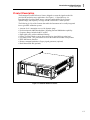
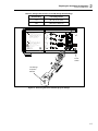
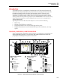
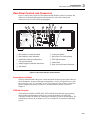
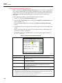
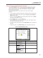
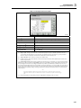
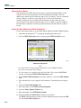
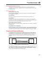
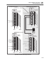
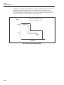
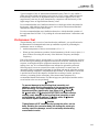
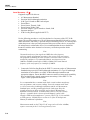
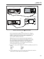
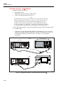
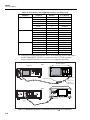
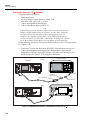
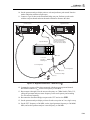
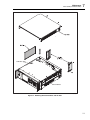
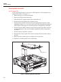
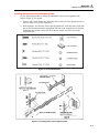
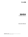
Local Operation
Introduction
3
Introduction
This chapter provides a comprehensive introduction of all of the external features and
functions on the Instrument, followed by instructions for operating the Instrument. The
introduction identifies each of the front- and rear-panel controls, connectors, and
indicators (including screens), and describes the intended use for each. Each feature
description is complete enough to allow the user to begin interacting with the controls
and to perform basic but practical operations on the Leveled Sine screen. For this reason,
many of the basic operations, such as editing data on a screen, are not repeated in the
operation instructions.
Operating Instructions at the end of this chapter are reserved for the following:
•
•
•
•
Initial setup
Making external hardware connections
Using features that are not obvious on the front and rear panel
Using the Instrument to create its intended RF Output: sine, modulated, and swept
signals.
Controls, Indicators, and Connectors
The front panel of the Instrument is shown in Figure 3-1. Each feature is identified with a
name and graphical grouping. The same name and graphic introduce the section and
paragraph(s) containing the description of the feature.
B
2
C
3
4
5
6
D
7
F
E
8
9
10
11
12
1
9610A/AF REFERENCE SOURCE
13
96xx
HEAD INTERFACE
A
RF OUTPUT
SINE
MOD
CONTROL
_/
7
ABC
8
9
GHI
JKL
MNO
4
5
6
PQRS
TUV
WXYZ
DEF
ALPHA
LOCK
OPER
NEXT
CHAR
SWEEP
UNITS
10V
PK
MAX
1
2
3
0
.
-
BKSP
EXP
SPACE
STBY
ENTER
SETUP
RF
COMMON
CONNECT
96xx HEAD
ONLY
21
A Head I/O Connectors
C
19
Output Function Keys
18
17
16
E
15
14
Keypad
Alphanumeric
Output Signal
Control
RF Output
B
20
(Modulate)
Display
ENTER
Screen Display
Data Fields
Status Bar
Soft Labels
Soft Keys
(Exponent)
(Backspace)
D
Field Editor
F
STBY/OPER Keys
Spin Wheel
(Operate)
Cursor Keys
(Standby)
ead10f.eps
Figure 3-1. Front Panel Controls, Indicators, and Connectors
3-3